
Networking and TCP/IP stack for HelenOS system · Networking and TCP/IP stack for HelenOS system...
95
Charles University in Prague Faculty of Mathematics and Physics MASTER THESIS Bc.Luk´aˇ s Mejdrech Networking and TCP/IP stack for HelenOS system Department of Software Engineering Master thesis supervisor: Mgr. Martin Dˇ eck´ y Study programme: Computer Science, Software systems 2009
Transcript of Networking and TCP/IP stack for HelenOS system · Networking and TCP/IP stack for HelenOS system...
Charles University in PragueFaculty of Mathematics and Physics
MASTER THESIS
Bc. Lukas Mejdrech
Networking and TCP/IP stack for HelenOSsystem
Department of Software Engineering
Master thesis supervisor: Mgr. Martin Decky
Study programme: Computer Science, Software systems
2009

Acknowledgements I wish to thank to my thesis supervisor, Mgr. Martin Decky,for his advice and direction in this research. I owe the greatest gratitude to my family,for making this thesis possible and their constant patience and support.
I hereby declare that I have created this work completely on my own and used noother sources or tools than the ones listed, and that I have marked any citationsaccordingly. I agree with lending and publishing this work.
Prohlasuji, ze jsem svou diplomovou praci napsal samostatne a vyhradne s pouzitımcitovanych pramenu. Souhlasım se zapujcovanım prace a jejım zverejnovanım.
In Prague Bc. Lukas Mejdrech
2
Nazev prace: Networking a TCP/IP stack pro system HelenOSAutor: Bc. Lukas MejdrechKatedra: Katedra softwaroveho inzenyrstvıVedoucı prace: Mgr. Martin DeckyE-mail vedoucıho: [email protected]
Abstrakt: V teto praci studujeme implementaci TCP/IP subsystemu. Duraz je kladenna navrh a implementaci respektujıcı koncept operacnıho systemu s mikrojadrem.Praktickou castı pak byl vyvoj TCP/IP subsystemu pro system HelenOS. Nejprvejsou popsany koncepty sıt’ove architektury a TCP/IP subsystemu obecne. Nasledujıspecificke aspekty kladene systemem s mikrojadrem. Dale je uveden navrh architek-tury a implementacnı rozhodnutı vlastnı implementace.
Klıcova slova: sıt’ove architektury, TCP/IP subsystem, HelenOS, ovladace sıt’ovehorozhranı
Title: Networking and TCP/IP stack for HelenOS systemAuthor: Bc. Lukas MejdrechDepartment: Department of Software EngineeringSupervisor: Mgr. Martin DeckySupervisor’s e-mail address: [email protected]
Abstract: Within this work we study networking and TCP/IP stack implementa-tion. The main interest is directed to the TCP/IP stack design and implementationrespecting the microkernel operating system concept. The practical part was a de-velopment of a TCP/IP stack for the microkernel operating system HelenOS. First,we describe the networking and the TCP/IP stack concept in general. The specialaspects of the microkernel concept follow. For the practical part, the architecturedesign and implementation decisions are included.
Keywords: networking, TCP/IP stack, HelenOS, network interface drivers
3
Contents
1 Introduction 61.1 Motivation . . . . . . . . . . . . . . . . . . . . . . . . . . . . . . . . . 6
1.1.1 History . . . . . . . . . . . . . . . . . . . . . . . . . . . . . . . 61.1.2 Implementation . . . . . . . . . . . . . . . . . . . . . . . . . . 7
1.2 Goals . . . . . . . . . . . . . . . . . . . . . . . . . . . . . . . . . . . . 71.3 Structure of the thesis . . . . . . . . . . . . . . . . . . . . . . . . . . 8
1.3.1 Style conventions . . . . . . . . . . . . . . . . . . . . . . . . . 8
2 Context of the thesis 102.1 Networking stack models . . . . . . . . . . . . . . . . . . . . . . . . . 102.2 HelenOS specific design . . . . . . . . . . . . . . . . . . . . . . . . . . 12
2.2.1 Kernel code . . . . . . . . . . . . . . . . . . . . . . . . . . . . 122.2.2 Modularity . . . . . . . . . . . . . . . . . . . . . . . . . . . . 122.2.3 Inter–process communication . . . . . . . . . . . . . . . . . . 13
2.3 Qemu emulator . . . . . . . . . . . . . . . . . . . . . . . . . . . . . . 132.4 N. E. T. . . . . . . . . . . . . . . . . . . . . . . . . . . . . . . . . . . 14
3 Networking stack design 153.1 New networking stack . . . . . . . . . . . . . . . . . . . . . . . . . . 15
3.1.1 Extent of the implementation . . . . . . . . . . . . . . . . . . 153.1.2 Architecture . . . . . . . . . . . . . . . . . . . . . . . . . . . . 163.1.3 Modular architecture . . . . . . . . . . . . . . . . . . . . . . . 163.1.4 Packet management system . . . . . . . . . . . . . . . . . . . 20
3.2 Networking stack modules . . . . . . . . . . . . . . . . . . . . . . . . 213.2.1 Central configuration module - net . . . . . . . . . . . . . . . 223.2.2 Network interface drivers . . . . . . . . . . . . . . . . . . . . . 233.2.3 Network interface layer . . . . . . . . . . . . . . . . . . . . . . 253.2.4 Inter–network layer . . . . . . . . . . . . . . . . . . . . . . . . 293.2.5 Transport layer . . . . . . . . . . . . . . . . . . . . . . . . . . 353.2.6 Application programming interface - libsocket . . . . . . . . . 373.2.7 Applications . . . . . . . . . . . . . . . . . . . . . . . . . . . . 38
4 Discussion 404.1 Implementation . . . . . . . . . . . . . . . . . . . . . . . . . . . . . . 40
4.1.1 HelenOS internals . . . . . . . . . . . . . . . . . . . . . . . . . 40
4
4.1.2 Support structures . . . . . . . . . . . . . . . . . . . . . . . . 414.1.3 Modules . . . . . . . . . . . . . . . . . . . . . . . . . . . . . . 464.1.4 Startup module - netstart . . . . . . . . . . . . . . . . . . . . 544.1.5 Extending the networking stack . . . . . . . . . . . . . . . . . 554.1.6 Qemu network . . . . . . . . . . . . . . . . . . . . . . . . . . . 584.1.7 N.E.T. user protocols . . . . . . . . . . . . . . . . . . . . . . . 58
4.2 Running and testing . . . . . . . . . . . . . . . . . . . . . . . . . . . 594.2.1 Applications . . . . . . . . . . . . . . . . . . . . . . . . . . . . 594.2.2 Software prerequisites . . . . . . . . . . . . . . . . . . . . . . 61
5 Evaluation 625.1 Nettest2 – data transfer performance . . . . . . . . . . . . . . . . . . 635.2 Nettest1 – the overall performance . . . . . . . . . . . . . . . . . . . 675.3 Ping – ICMP echo performance . . . . . . . . . . . . . . . . . . . . . 695.4 Conclusion . . . . . . . . . . . . . . . . . . . . . . . . . . . . . . . . . 70
6 Other architectures 726.1 BSD . . . . . . . . . . . . . . . . . . . . . . . . . . . . . . . . . . . . 726.2 Linux . . . . . . . . . . . . . . . . . . . . . . . . . . . . . . . . . . . 736.3 Windows . . . . . . . . . . . . . . . . . . . . . . . . . . . . . . . . . . 746.4 Minix . . . . . . . . . . . . . . . . . . . . . . . . . . . . . . . . . . . 74
7 Conclusion 76
8 Terms and abbreviations 78
Bibliography 81
A Test results 85
B UML diagrams 88B.1 Networking stack overview . . . . . . . . . . . . . . . . . . . . . . . . 88B.2 Module parts interaction . . . . . . . . . . . . . . . . . . . . . . . . . 90B.3 Network interface initialization . . . . . . . . . . . . . . . . . . . . . 92B.4 Data transfers . . . . . . . . . . . . . . . . . . . . . . . . . . . . . . . 94
5
Chapter 1
Introduction
1.1 Motivation
In this work we analyze, compare, design and implement a networking stack whichis an operating system’s subsystem connecting computers into networks. Althoughcomputer networks are in massive use these days there is no variability in referenceimplementations. Most of them are monolithic, having all the networking function-ality bundled in one large module, although the stack is internally layered. Thetarget implementation introduces modular architecture into the networking stack.This means building the stack up from smaller modules where each module encap-sulates and provides one area of functionality, a protocol for example. They will beseparate server modules each running as one task in the target operating system 1.The stack is intended to be integrated to HelenOS, a microkernel operating systembeing developed at the Faculty of Mathematics and Physics, Charles University inPrague. The microkernel design and philosophy are briefly described as well as its re-quirements for additional modules’ architecture. The result of this thesis makes effortto become a modular TCP/IP networking stack proof–of–concept implementation.
1.1.1 History
The history of computer networks began in late October 1969 when the ARPANETproject was born [25]. Before that time computers were isolated individuals. Sincethat time they are able to communicate with each other.
The ISO/OSI model was developed to standardize computer communication andis the first and most comprehensive networking model. It defines seven layers offunctionality and abstraction. Unfortunately the model does not contain concreteprotocols and the applicants did not have anything to follow. Another problem wasits megalomaniac attitude. The model tries to solve almost all possible questions anduses of interconnected computers. Therefore it was far to complex to implement andspread protocols respecting it. Furthermore, the applicants had to pay a significantamount of money just to obtain the detailed model specification.
1It can be viewed as a service oriented subsystem.
6
However, a different approach succeeded, the TCP/IP model. The model wasbased on simple and concrete protocols which were used to build up what was reallyneeded. Its bottom–up approach led to its current world domination. This protocolfamily is called the TCP/IP protocol suite where the IP stands for the inter–networkprotocol and is the base protocol of the suite. It works on the principle of the besteffort, the protocol tries to do its best to deliver data from one computer to another.The word “try” is the key as nothing is guaranteed. On the other hand TCP isprobably the most used protocol on top of the IP protocol, it offers reliable connectionbetween two computers. The TCP/IP suite contains many protocols covering mostaspects of computer communication. Most of attention of this work will be drawn tothis suite.
The protocols and design concepts are published as numbered RFCs which arepublic and rather technical documents covering usually only one topic, a protocol forinstance. There is an RFC for each protocol in the suite, however, some protocols areextended in many RFCs. For example, there is one base RFC of the TCP protocolbut hundreds of RFCs extending or altering its functionality in any way. RFCs donot become obsolete too often, they are usually updated or extended. The actualbase RFCs of the TCP/IP suite come from early 1980s.
1.1.2 Implementation
As it was mentioned before, the TCP/IP protocol suite is extensively used. Com-puters usually do not have any other option how to connect themselves into currentcomputer networks. One of the goals of this thesis was to develop a modular TCP/IPstack for a microkernel operating system HelenOS.
Porting an existing stack was also an option. It would have brought in manymore features in exchange to the clean modular design as mentioned before. SomeHelenOS-specific workarounds would have also looked odd in the system as a whole.
Therefore a new implementation is introduced. It is designed from scratch andbased only on the relevant RFCs. The modular design and inter–process communi-cation of the microkernel system are respected, of course. A modular and extensiblearchitecture which seems to the author to be trusty to its purpose, as this archi-tecture complies with the overall architecture of the target microkernel system. TheTCP/IP protocol suite is very well described and documented in RFCs and almostno other resources are needed.
1.2 Goals
This work follows a few goals. The main goal was a networking stack implementa-tion respecting the microkernel design of the target operating system. This emergedfrom the fact that the target HelenOS operating system did not have a network-ing stack. A new concept was to be thought up and designed. The networking stackmoves HelenOS to the next level. It brings the possibility to communicate with othercomputers and systems.
7
The second goal is connected to the first one. This implementation might be-come, with a bit of luck, the reference implementation of a modular TCP/IP stack.Many believe that microkernel operating systems will have bright future and modu-lar architecture is the right way to go. Probably the most famous propagator of themicrokernel design is Andrew Tanenbaum, an author of many publications aboutoperating systems [27] and the microkernel operating system Minix. There are manyadvantages and disadvantages, attitudes and reasons for and against both the mono-lithic and microkernel operating systems 2. Most often mentioned disadvantages ofthe microkernel design are inefficiency and insufficient flexibility. Both are explainedand at least partly invalidated in the work of Jochen Liedtke [9].
There is also a research capacity to compare the modular stack implementationoverhead to the monolithic approach. For this purpose the compilation into manysmall modules or one large module is designed and supported. We will measure andanalyze differences between these two approaches.
1.3 Structure of the thesis
Here is a description of the master thesis structure and content of single sections:
Chapter 2 An introduction to the context of the work, the networking stack modeland HelenOS.
Chapter 3 A summary of the modular architecture requirements with the proposednetworking stack design. It includes detailed networking model layers, analysisand proposed modules’ description.
Chapter 4 A discussion about implementation decisions and problems.
Chapter 5 Architecture evaluation and comparison results.
Chapter 6 A few other networking stack implementations.
Chapter 7 A conclusion of the thesis.
1.3.1 Style conventions
The text follows a few style conventions:
• File and directory names are printed as source file.c.
• All referenced header and source files are located in the HelenOS source subdirectory uspace/srv/net/ if not stated otherwise.
• Inter–process message names are printed as MODULE MESSAGE (argument).
• Code samples are printed in blocks
2Many were mentioned in the so–called Tanenbaum–Torvalds debate [1].
8

command;
function_call(argument);
• Constants and functions in the text are printed as ‘‘constant’’ and func-tion(argument) respectively.
9
Chapter 2
Context of the thesis
2.1 Networking stack models
The networking stack can be divided into a few layers. Each of them representsan abstraction for a particular functionality. The ISO/OSI model [31] defines sevenlayers whereas the TCP/IP stack defines only four or five [26]. The TCP/IP stacklayer count varies sometimes because the bottommost layer may be split into two.Although this work focuses on the TCP/IP stack the ISO/OSI model should bementioned first as it is more general. Its concept uses seven layers. Each layer usesthe layer underneath and provides some functionality to the upper one. Except somerare exceptions layers should not traverse more than one level 1. The layer abstractionis that layers of the same level but on different hosts communicate with each otherusing lower layers transparently. A short description of the ISO/OSI layers followsand their scheme is in the Figure 2.1. The TCP/IP stack is described in detailthe Section 3.2.
Physical layer
The bottommost is a physical layer. This layer transfers the smallest portions ofdata between network interfaces. Namely zeros and ones using electrical or opticalimpulses etc. Not only two network interfaces can be aware of the communication.Wireless networks are the best example that every network interface can hear thecommunication. Data unit being transferred by this layer is a bit. Some devices arecapable to transfer more bits at once. In the sense of more bits at once, without anyfurther knowledge about the data. This layer is about the transport medium, wires,air etc. and the transport perception.
Data link layer
The next layer is a data link layer. Whole data blocks are transferred between networkinterfaces. The source host directs the data block using the destination host’s address.The addresses are physical, usually assigned by network interface manufacturers. The
1So called cross layer optimization [24].
10
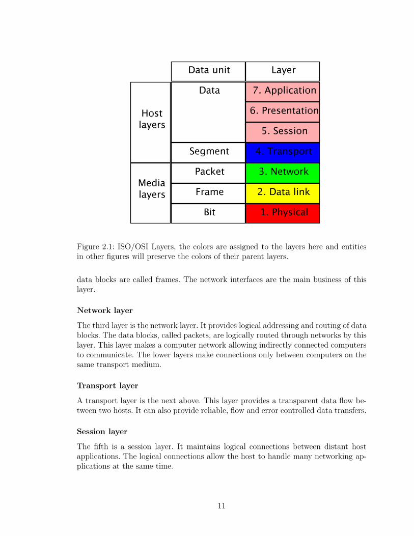
Figure 2.1: ISO/OSI Layers, the colors are assigned to the layers here and entitiesin other figures will preserve the colors of their parent layers.
data blocks are called frames. The network interfaces are the main business of thislayer.
Network layer
The third layer is the network layer. It provides logical addressing and routing of datablocks. The data blocks, called packets, are logically routed through networks by thislayer. This layer makes a computer network allowing indirectly connected computersto communicate. The lower layers make connections only between computers on thesame transport medium.
Transport layer
A transport layer is the next above. This layer provides a transparent data flow be-tween two hosts. It can also provide reliable, flow and error controlled data transfers.
Session layer
The fifth is a session layer. It maintains logical connections between distant hostapplications. The logical connections allow the host to handle many networking ap-plications at the same time.
11
Presentation layer
There is also a data presentation layer. Transferred data have to be interpreted in thesame way on both communicating sides. There can be highly different devices on eachend of the connection. Therefore some standardization or pre–transport negotiationis necessary. A network byte order is the best example. The big–endian byte order 2
is used in the networking.
Application layer
The last layer is an interface for applications willing to use the networking stack. Itoffers host identification, connection establishment and data flow to the end appli-cations.
2.2 HelenOS specific design
In this section we describe the target system of the networking stack. HelenOS isunder development of a research group at the Faculty of Mathematics and Physics,Charles University in Prague. It follows the microkernel design [8].
2.2.1 Kernel code
In operating systems there are two types of code execution, the kernel or privilegedmode and the userspace or normal mode. Hosted applications run in the user spacemode. The kernel code runs in a privileged mode. This mode allows access to allhardware, whole available memory including other tasks’ memory and all parts ofthe operating system as well. Therefore any bug in the kernel mode may lead tosystem instability, data loss or even hang ups.
The smaller the code is the easier it is to double or triple check it. While studyingthe microkernel design, an interesting observation was made, that the kernel code canbe really minimal [27]. The microkernel design attempts to minimize the kernel codeand modularize the system as a whole. The kernel code needs to handle hardwareinterrupts, host applications and provide hardware access to drivers. HelenOS followsthe thought that only really necessary parts should run in the privileged mode.
2.2.2 Modularity
As the microkernel design runs little code in the privileged mode it is easier to runmore stable. In addition some operating system tasks do not have to run in theprivileged mode at all. Many drivers or abstraction layers function well even whenplaced into the user space. The possible inconsistency due to code defects stays localin the task itself if it runs in the user space. The kernel basically gives no otheroption. Therefore much of the standard operating system functionality is brokeninto small pieces running in the user space. Such pieces can be called modules. They
2The most significant byte is stored first, with lowest address.
12
offer services to other modules so the overall architecture can be thought of as theservice oriented architecture.
Furthermore the modular design may be used to reduce the overall complexityand ease development. The system is broken into functional components with definedinterfaces [6]. The inner implementation is encapsulated and other components useit as a black box. The overall functionality is then built up from these components.
Another possible extension to the current view of an operating system is the pos-sibility to check and restart defect modules. Either by polling the modules whetherthey are operational or by check–pointing their state.
2.2.3 Inter–process communication
Tasks communicate with each other through open connections using inter–processcommunication. The standard message passing mechanism is used. The sending taskpasses a message and can wait for a reply. The receiving task picks up the messageand processes it replying the answer. Standard messages can have up to five integerarguments and up to five integer return values. The term “phone” is used in HelenOSfor the task’s identifier of an open connection.
HelenOS provides an asynchronous library which maintains these connectionsand creates a fibril for each of them. Fibrils are the smallest points of executionin the user space. They are like threads in a main thread. Each connection fibrilprocesses messages only of its connection. This leads to parallelism where there canbe many messages processed at a time. The client connections are isolated and donot interfere with each other.
A memory block can be also copied between two tasks. This is useful for largedata blocks. The memory block is copied if the tasks agree. The kernel does the jobin this case.
The last possibility is to share memory blocks. The kernel maps the memory blockinto the address space of the target task. So both tasks are able to use the sharedmemory. Great care has to be taken and the memory access needs to be synchronizedor standardized.
2.3 Qemu emulator
As it is a bit hard to develop an operating system on a real hardware a simulatorwas used. A simulator gives the pleasure to develop test and debug the system inan efficient way. There is no need to dedicate a whole computer to run the system.Neither to transfer the built binaries to be able to execute them. Qemu is run ona host operating system and runs a guest operating system as if it was a standalonecomputer.
Furthermore, Qemu has a simple network interface. It emulates, among others,an ISA NE2000 network interface. ISA cards have the nice feature that the deviceIO port has to be statically set. This is the memory address used to communicate
13
with the device. Device registers are mapped there and the device is controlled byreading and writing them.
2.4 N. E. T.
In order to test and debug a networking stack a universal networking application ishighly recommended. The stack itself contains functions and their counterparts whichcan be tested together. However, this would not reveal possible design mistakes, onlyprogrammatic. For example the checksum computation and check can function welltogether but it might be a different implementation than the protocol actually uses.Therefore an external application using another networking stack implementation isbetter as it tests these functions with their external counterparts. This should revealboth programmatic and design mistakes.
This application was developed as a testing tool of networking communication afew years before this work began. It is a modest application capable of communicationusing the lowest protocols, namely UDP and TCP. It is designed to provide usefulnetworking communication information of the local and remote computers. The basicapplication features are:
• Sending and receiving packets of the TCP and UDP protocols on various portsas both the client and the server,
• Listening for connections,
• Ping and trace,
• Active ports enumeration,
• Getting host information including addresses,
• Getting protocol capabilities, configuration and information,
• Logging all printed information into a file, and
• GUI.
Despite the fact that this simple functionality is sufficient for the networkingstack testing, the main feature is that the application allows users to define theirown protocols. The whole process starting by a used protocol, connecting sequence,confirmation data, statuses and disconnecting sequence may be defined.
14
Chapter 3
Networking stack design
3.1 New networking stack
For the microkernel HelenOS a completely new networking stack was designed. Thedetailed description of requirements, architecture, support structures and modulesfollows.
3.1.1 Extent of the implementation
The networking stack was intended to implement current basic standards of theTCP/IP Stack. The standards are described in the form of RFC documents. Therelevant RFCs are mentioned where appropriate. All the additional features of theTCP/IP Stack are far beyond the scope of this work. There are hundreds of ex-tensions, alterations or concretions on top of the core design. Only the minimalisticfunctionality allowing the stack to function was to be implemented. The detailedfunctional rules are enumerated in later sections closer to their topics. The imple-mentation goals were:
Initialize and use a real network interface network interface recognition, con-figuration, initialization and shutdown, sending and receiving packets, faultand state reception,
Support for more than one network interface advanced modular and depen-dency design, IP routing tables,
Implement the TCP/IP Stack IP, ARP, ICMP, UDP and TCP protocol mod-ules,
Implement the BSD socket interface for applications a socket application li-brary providing connecting and sending and receiving data functionality, and
Demonstrative applications ping, echo and similar applications.
The standardized TCP/IP Stack implementation allows the stack to coexist in mostof the current networks whereas the standardized BSD socket interface eases portingof networking applications.
15
As HelenOS is written in the C language and it is an operating system withits own libc library, there are not many support structures. At least a basic ob-ject oriented approach is achieved by using structures as data classes and sets offunctions manipulating them as methods. Implementation of the support of C++in HelenOS would involve implementation of the C++ library. RTTI, inheritance,virtual methods, STL and integration with IPC would increase the scope of thethesis dramatically. Without this features there wouldn’t be any additional benefitscompared to C. So the networking stack is written in C.
3.1.2 Architecture
For the stack development two approaches are possible. One monolithic–like moduleand separate device drivers and on the other side a fully modular architecture canbe used.
The monolithic–like module and separate device drivers have one big advantage– there is no internal inter–process communication at all. There are only normalfunction calls internally. The union of functional modules offers also the possibilityto keep shared data on one address in the address space which decreases resourceconsumption. The performance is probably the most obvious reason to use this de-sign. Nevertheless, there are disadvantages as well. Parts of this system are physicallybound to each other. These parts correspond to functional modules in the meaning ofreference model layers. Programmers are allowed to develop a bit fuzzy design withmixed global data structures and some possibly dirty workarounds and bypassesbetween functional modules. The stack is compact and extending it could involveinternal changes. The stack cannot be divided easily either. Functional modules candepend on each other and function calls cannot be easily recognized and isolated.This is just a hypothesis if someone wants to exclude particular functionality. It canbe, for example, an attempt to provide a special purpose networking stack based ona simplified one.
The fully modular architecture has every functional unit in a separate module.The modules communicate only using well defined interfaces. It needs a bit moredetailed analysis of the modules’ cooperation. Also the common data structures haveto be distributed to all concerned modules. This approach is preferred in order todemonstrate a functional modular stack running in a microkernel operating system.There is one important advantage – each functional module is physically isolated.The functional modules have well defined interfaces and could be fully replacedwithout the need to modify any other modules. New modules are free to connect tothis interfaces and extend the stack. There is also well defined module dependencyand modules can be excluded.
3.1.3 Modular architecture
In this section we describe the module concept in general. The networking stack issplit into many small modules which reduces the overall complexity and encapsu-lates functionality. Each module represents an actual implementation of a particular
16
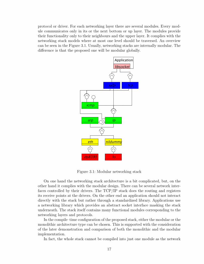
protocol or driver. For each networking layer there are several modules. Every mod-ule communicates only in its or the next bottom or up layer. The modules providetheir functionality only to their neighbours and the upper layer. It complies with thenetworking stack models where at most one level should be traversed. An overviewcan be seen in the Figure 3.1. Usually, networking stacks are internally modular. Thedifference is that the proposed one will be modular globally.
Figure 3.1: Modular networking stack
On one hand the networking stack architecture is a bit complicated, but, on theother hand it complies with the modular design. There can be several network inter-faces controlled by their drivers. The TCP/IP stack does the routing and registersits receive points at the drivers. On the other end an application should not interactdirectly with the stack but rather through a standardized library. Applications usea networking library which provides an abstract socket interface masking the stackunderneath. The stack itself contains many functional modules corresponding to thenetworking layers and protocols.
In the compile–time configuration of the proposed stack, either the modular or themonolithic architecture type can be chosen. This is supported with the considerationof the later demonstration and comparison of both the monolithic and the modularimplementation.
In fact, the whole stack cannot be compiled into just one module as the network
17
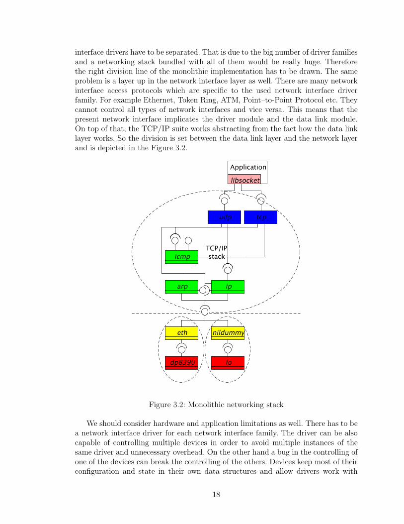
interface drivers have to be separated. That is due to the big number of driver familiesand a networking stack bundled with all of them would be really huge. Thereforethe right division line of the monolithic implementation has to be drawn. The sameproblem is a layer up in the network interface layer as well. There are many networkinterface access protocols which are specific to the used network interface driverfamily. For example Ethernet, Token Ring, ATM, Point–to-Point Protocol etc. Theycannot control all types of network interfaces and vice versa. This means that thepresent network interface implicates the driver module and the data link module.On top of that, the TCP/IP suite works abstracting from the fact how the data linklayer works. So the division is set between the data link layer and the network layerand is depicted in the Figure 3.2.
Figure 3.2: Monolithic networking stack
We should consider hardware and application limitations as well. There has to bea network interface driver for each network interface family. The driver can be alsocapable of controlling multiple devices in order to avoid multiple instances of thesame driver and unnecessary overhead. On the other hand a bug in the controlling ofone of the devices can break the controlling of the others. Devices keep most of theirconfiguration and state in their own data structures and allow drivers work with
18
them through memory address spaces. Therefore the driver itself is almost statelessand it can handle more devices at a time without any disruption. There can beseveral network interfaces controlled by their drivers in the system at a time. Eitherusing the same or several drivers 1. The TCP/IP stack does the routing and registersits receive points at the drivers.
The applications willing to use the networking capabilities of the system use a li-brary. The socket interface was developed to unify the abstraction of the networkingstack. The applications using this interface can be ported to and function with othernetworking stack using the same interface. The library is only a wrapper providingthe networking interface to applications.
Inter–process communication
In order to successfully orchestrate modules their cooperation should be carefully an-alyzed. There is an interface designed for each of the modules to publish its function-ality. There are layer– and module–specific interfaces. The layer interface is a generallayer functionality whereas the module specific serves its special purpose. This allowslayer abstraction where more similar modules can work in the same layer and otherlayer modules could use either of them. The network and network interface layermodules are the best example as we discussed them in the context of the monolithicdivision line. Only known and almost hardwired connections would be possible oth-erwise. The driver just sends packets and state notification to its network interfacelayer buddy but the TCP protocol has to distinguish between the IP and the ICMPprotocol. A module usually implements its layer interface.
Server modules should be able to serve many connections as they offer theirservices to others. They are also clients of other server modules. It would be veryinefficient if a module had to wait until another message gets processed. Some com-plex messages can take a long time to complete. They can involve several other IPCqueries. Therefore the networking stack should work in parallel.
On the other hand the parallelism lays stress on global data structures in theserver modules. The global data have to be protected against multiple fibrils pro-cessing messages. Most of the messages can be easily divided into two groups. Somedoes not change the global data, but they need to read them. For example if a packetgets passed through a module, only the actual setup is read, the packet is processedand passed to another module. Other messages change the module setup. For exam-ple the initialization of a new protocol or device involves reading configuration orsetting up routing tables. The most adequate synchronization primitives are there-fore the read–write locks 2. The rest of the messages can change the module setupon some conditions. They either swap the lock from reading to writing or lock it forwriting. It depends on the likelihood of the writing process.
1An Ethernet router contains many instances of the same network interface to allow many hoststo connect whereas a host can contain an Ethernet and WiFi network interfaces.
2The read–write lock can be hold by multiple readers or by only one writer at a time.
19
3.1.4 Packet management system
A packet in the sense of the networking stack is a block of formatted data. Networkingstack processes packets and have to pass them between its modules. The memoryblock can be passed between modules via inter–process communication messages.Unfortunately, this would be highly ineffective as the packet data would get copieddue to the task isolation. In the monolithic–like stack this would happen only at thetop and at the bottom of the stack, from client applications and to network interfaces.If the stack is to be modular the inter–process communication performance is thecutting edge. The fastest way is to transparently share the packet as an addressspace page. So only packet identifiers get transferred. This rapidly increases thestack performance. There is no internal copying of data. They are copied only at thetop and at the bottom of the stack as in the monolithic case. However, the sharedpacket memory block has to be distributed between the concerned modules first.Strict rules need to be stated and obeyed as well:
1. Only modules in the networking stack and network interface drivers may haveaccess to packets,
2. Only provided packet manipulation functions must be used,
3. A module processes a packet only if it is the exclusive owner of the packet:
• The module becomes the exclusive owner if
– requests a new packet, or
– is asked to process the packet
• The module is the exclusive owner until
– passes the packet to another module, or
– releases the packet.
The packet structure itself should never be accessed directly. Packet manipulationfunctions are provided in a form of a library described in the Section 4.1.2.
Architecture
The networking stack packet management system consists of a packet server anda library. The packet server needs to be implemented by one well–known module inthe stack. Its job is to manage packets. All packets in the stack are in possessionof this module. The packet library should be part of each module willing to processpackets. It provides packet mappings into the task’s address space and communicateswith the packet server. Other modules can request a new packet and the packet servercreates a new one or reuses an old one. Until the packet is released again it cannotbe reused by the server. Any stack module can release the packet, not only therequesting one. If a module is asked to process a packet it uses the packet libraryto get the packet. If the packet has already been used, the library finds the packetmapping to the task’s address space. If not, the library requests the packet from
20
the packet server. The packet server shares the packet as a memory block with therequesting task and the library returns the newly shared packet.
Packet processing
There are two directions of packet processing. A network interface driver uses cleanor new packet to provide the received data to the networking stack. The transferredapplication data are incrementally unwrapped on their way through all the modules.
The topmost layer uses clean or new packets to send data through the networkingstack. The transferred application data are incrementally wrapped on their waythrough all the modules. The processing time is crucial, so we would like to avoid datacopying as much as possible. There has to be some infrastructure developed aroundthe packet processing. As we mentioned before, each module wraps or unwraps thepassed data. Each module knows how to do its job and does not have to be aware ofthe others. The idea is to keep the application data on one place during the wholeprocess. The modules then incrementally just cut or prefix and/or suffix their specificwrappings.
Another option would be a list of succeeding memory blocks 3. Each module justprefix or suffix its wrapping as another memory block. This increases the complexityas one packet is split into—possibly many—small pieces. For example a checksumcomputation of such a packet have to jump from one piece to another. Furthermorethis is not a universal solution. All modules have to be able to process such blocklists. However, some network interfaces are able to transfer only continuous block ofdata 4. The blocks need to be serialized for them first. Unfortunately, this would beanother data copying decreasing performance.
The packet size is loosely limited only by the MTU setting. However, the IPprotocol, for instance, allows content only up to 65 535 octets long. The MTU maybe specific for each device, network or protocol used. New outgoing packets haveto be created with the MTU size taken into account. The IP protocol supportspacket fragmentation for “small packet” networks. The upper protocols do not haveto respect this setting as it is transparent for them. However, they could decreaseload of their underlying IP module by doing so.
3.2 Networking stack modules
The HelenOS networking stack is described from the bottom layer up according tothe TCP/IP model. The relevant ISO/OSI layers are referenced where appropriate.Each module description is followed by its public interface. Module interactions aredescribed and some even depicted in UML diagrams. For a visual representationof the whole stack in an UML diagram see the appendix Section B.1. A centralconfiguration module is described first.
3The technology of transferring and receiving succeeding blocks of data as one frame is calledscatter–gather or vectored input–output.
4They can use only a simple DMA access to read a continues block without any other option,for example.
21
3.2.1 Central configuration module - net
The central module is the heart of the networking stack. This module implements thepacket server, reads the networking configuration and starts required service modules.The configuration consists of the general networking stack and network interfacespecific parts. The stack configuration is textual. Numeric settings are parsed asintegers, switches starting with ′y′ as enabled. The general configuration specifies:
MTU The default maximum transmission unit. Set to ‘‘1500’’.
ICMP ERROR REPORTING The Internet Control Message Protocol errorgeneration and reporting switch. Set to ‘‘yes’’.
ICMP ECHO REPLYING The Internet Control Message Protocol echo replygeneration and reporting (ping) switch. Set to ‘‘yes’’.
IPV The default Internet Protocol version. Set to ‘‘4’’.
IP ROUTING The general IP routing switch. Set to ‘‘no’’.
UDP CHECKSUM COMPUTING The User Datagram Protocol optional out-going traffic checksum computation switch. Set to ‘‘yes’’.
UDP AUTOBINDING The User Datagram Protocol optional automatic bindon send if not bound switch. Set to ‘‘yes’’.
The network specific configuration contains:
NAME The network interface name.
NETIF The network interface driver module name.
NIL The network interface layer module name.
IL The inter–network layer module name.
The generic stack configuration can be overridden by the network interface specific.Any other configuration is also tracked so stack modules are free to add their specificsettings. Module specific settings are mentioned at each of them. Modules can querythe net module about a general or specific setting by its label. If the network interfacespecific setting is not found the general stack configuration is searched then.
This module starts needed modules of the stack and initializes network interfaces.The networking stack startup is described later in the Section 4.1.4.
net interface
The net module offers the following interface:
• net connect module(net service) function and its backingIPC M CONNECT ME TO message to connect to the net module returningthe connection phone.
22
• net free settings(configuration, data) to release the returned setting values.Should be used in conjunction with either general or network interface spe-cific configuration request. If used in a bundle module, no memory is freed asthe values buffer is empty.
• net get device conf req(net phone, device id, configuration, count, data);NET NET GET DEVICE CONF to read the network interface specific config-uration. The requested setting labels are transferred as measured string fieldand values in the opposite way. If used in a bundle module the values are notcopied to the buffer and must not be freed.
• net get conf req(net phone, configuration, count, data);NET NET GET CONF to read the general configuration. Similar to the pre-vious one.
3.2.2 Network interface drivers
A network interface, often referred as a network card, is the most important part ofthe stack. Roughly said, it is used to communicate with the outside world. Thereforeall the outgoing and incoming traffic goes through the network interface. This is thebottommost layer in the ISO/OSI model, the physical layer.
There are a few basic capabilities of a network interface driver which need tobe implemented. The most important ones are sending and receiving packets. Thedriver should be able to start and stop the device and accept a configuration from thenetworking stack. The devices can be present and configured but temporary disabledif desired. Controlling multiple devices is an optional feature.
Drivers can also provide some diagnostics and statistics for the system whichshould be updated appropriately.
The driver should be capable of:
• Discovering a device,
• Configuring a device,
• Starting a device,
• Stopping a device,
• Sending a packet,
• Providing a received packet,
• Returning device usage statistics, and
• Returning the current state of a device.
23
A network interface layer module can register itself as the packet supplier and con-sumer of the device. Incoming packets are delivered to that module asynchronously.
The network interface layer could also poll the driver frequently to obtain receivedpackets. This option is not used as it increases overhead and is inefficient when thereare no packets. On top of that if the driver is not queried often enough, the receivedpackets can fill its buffers and may be discarded.
The driver can use device specific hardware settings such as input/output addressspace and IRQ. The driver then registers and handles IRQ events. Network interfacedrivers obtain the IRQ numbers and IO port addresses at the device initialization.Device configuration entries IRQ and IO, respectively, are forwarded to the driver.
Network interface driver interface
The network interface driver modules offer the following interface:
• netif bind service(netif service, device id, calling service, receiving callback)function and its backing IPC M CONNECT TO ME message to register itselfas the received packets consumer.
• netif get addr req(netif phone, device id, address, data);NET NETIF GET ADDR to read the network interface hardware address.
• netif probe req(netif phone, device id, IRQ, io); NET NETIF PROBE to probeif there is a device at the specified memory address using the specified IRQ.
• netif send msq(netif phone, device id, packet, sender service);NET NETIF SEND to send the packet via the specified device.
• netif start req(netif phone, device id); NET NETIF SEND to start the speci-fied device.
• netif stats req(netif phone, device id, stats); NET NETIF STATS to read thespecified device’s usage statistics.
• netif stop req(netif phone, device id); NET NETIF STOP to stop the specifieddevice.
Loopback network interface - lo
The loopback network interface is a special device which returns all outgoing packetsback as incoming ones. The motivation for this device is to enable network commu-nication between both server and client applications running on the same host. Theapplications are connected as being remote, however, the communication goes justthrough the local networking stack. There are no problems with carrier, protocolsand formats and “the other side” is always reachable 5. There is also no need of a realnetwork interface device.
5Although the other application may not be reachable.
24
The lo driver is designed as a standalone module with capabilities of a regulardevice driver. The driver itself creates a virtual device and returns all outgoingpackets as incoming incrementing the usage statistics accordingly. This is due tothe requirement of usage statistics and transparent driver interface. In the extremecase only the user knows that this network interface is the loopback. Therefore theloopback does not need any special configuration.
NE2000 network interface driver - dp8390
The main goal of the networking stack is to connect the computer to a computernetwork. A real network interface enabling us to connect to the outside world isneeded. There are hundreds of network interfaces and supporting them would bea long term run. For the successful networking stack demonstration one is enough.A NE2000 network interface family was chosen 6. A lot of its clones 7 exists which isone of the main reasons. Another one is its simplicity. An ISA version of this networkinterface resides in the address space on one of the specified locations.
Qemu emulates the NE2000 network interface as well. So the decision was made tosupport this one. A more recent chip DP8390D by National Semiconductor actually.This chip is well documented in the data sheet [7] on the manufacturer’s website.
3.2.3 Network interface layer
The network interface layer is the data link layer in the ISO/OSI model. This layertransfers whole blocks of data between two network interfaces, possibly on differenthosts. The network interface layer module is specific for the type of network thecomputer is connected to.
There can be many network interface layer modules implementing various types ofnetworks such as Ethernet, TokenRing etc. The network type is partly determined bythe used network interface. Not all network interfaces support all types of networks.The NE2000 supports only the Ethernet.
The interface for the upper layers is transparent of the network type. So thebundle build is supported only with drivers, not the upper stack.
The network interface layer module can also distribute packets between the upperlayer modules according to the inner frame protocol. There can be more than oneupper layer module using this one for sending and receiving packets. The upperservice module has to register itself and the network interface layer module can takeinto account the packet distribution. Packets are passed one by one. Concrete rulesare module specific and will be described in the later example of IEEE 802.3.
Network interface layer interface
The network interface layer modules offer the following interface:
6This is a product line started in early 1990s originally by Novell. It became de facto a standardbecause it spread widely thanks to its low price.
7Clone is a compatible network interface, it behaves and can be controlled in a very similarway.
25
• For the upper stack:
– nil bind service(nil service, device id, calling service, receiving callback)function and its backing IPC M CONNECT TO ME message to registeritself as the received packets consumer, there can be more consumers perdevice based on the stated service.
– nil device req(nil phone, device id, mtu, netif service);NET NIL DEVICE to register a device and its driver.
– nil get addr req(nil phone, device id, address, data); NET NIL ADDR toread a network interface hardware address.
– nil get broadcast addr req(nil phone, device id, address, data);NET NIL BROADCAST ADDR to read a network interface broadcastaddress.
– nil packet size req(nil phone, device id, addr len, prefix, content suffix);NET NIL PACKET SPACE to read maximum packet dimensions, min-imal address length, prefix and suffix and maximum content length inbytes.
– nil send msq(nil phone, device id, packet, sender service);NET NIL SEND to send a packet (queue) via the specified device.
• For drivers:
– nil device state msg(nil phone, device id, state);NET NIL DEVICE STATE to process the device state change.
– nil received msg(nil phone, device id, packet, target service);NET NIL RECEIVED to process the received packet.
Dummy network interface layer - nildummy
There is one special network interface layer module, a dummy one. It is used just tobridge communication between a network interface driver and the upper stack. Onemodule is allowed to register itself as a consumer of received packets. Only devicesregistered with the nildummy module are available.
The purpose of this module is to keep the layer division. A driver does not have toprocess network interface layer messages nor sends them to an upper inter–networklayer module. The messages are translated appropriately. Furthermore, the invariantthat layers should not traverse more than one level is kept as well.
The most obvious network interface driver lying underneath is the loopback onewhere no added functionality is needed.
IEEE 802.3 - eth
One of the most widely used network types is the, informally called, Ethernet. Thetechnology is standardized as IEEE 802.3. The history of the original Ethernet begunat XEROX PARC in 1976 [12]. The name comes from an ether, a fluid allowing
26
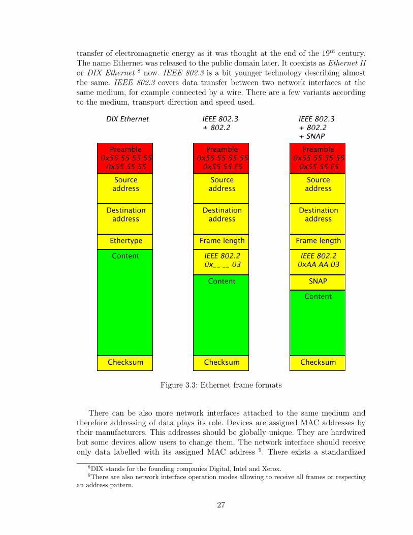
transfer of electromagnetic energy as it was thought at the end of the 19th century.The name Ethernet was released to the public domain later. It coexists as Ethernet IIor DIX Ethernet 8 now. IEEE 802.3 is a bit younger technology describing almostthe same. IEEE 802.3 covers data transfer between two network interfaces at thesame medium, for example connected by a wire. There are a few variants accordingto the medium, transport direction and speed used.
Figure 3.3: Ethernet frame formats
There can be also more network interfaces attached to the same medium andtherefore addressing of data plays its role. Devices are assigned MAC addresses bytheir manufacturers. This addresses should be globally unique. They are hardwiredbut some devices allow users to change them. The network interface should receiveonly data labelled with its assigned MAC address 9. There exists a standardized
8DIX stands for the founding companies Digital, Intel and Xerox.9There are also network interface operation modes allowing to receive all frames or respecting
an address pattern.
27
broadcast address to send data to all listening network interfaces.The frame format differences are described in this paragraph and depicted in
the Figure 3.3. Both DIX Ethernet and IEEE 802.3 use almost the same headerpreceding the actual frame data. A frame type or ethertype header field in DIX isused as a frame length in IEEE 802.3. The basic frame type was used to distinguishthe inner frame protocol, the higher protocol transferring its own data inside theEthernet frame.
On the other hand the frame length offers better consistency check. Furthermore,the length is important as there is a minimum length limited. The frame content hasto be at least 46 bytes long. It is padded with zeros if shorter. The frame lengthreveals such a padding whereas the frame type does not and the inner protocol orprotocols have to find it out by themselves.
The IEEE 802.3 does support frame type as well, but in an additional IEEE802.2 header. The usual frame types are all numbers higher than 1536 (0x0600). SoIEEE decided to restrict frame type to be higher than 1536 and frames are allowedat most 1500 bytes of data. The coexistence of this two frame formats is explicitlypossible. Frames can be easily recognized by the frame type/length header field.
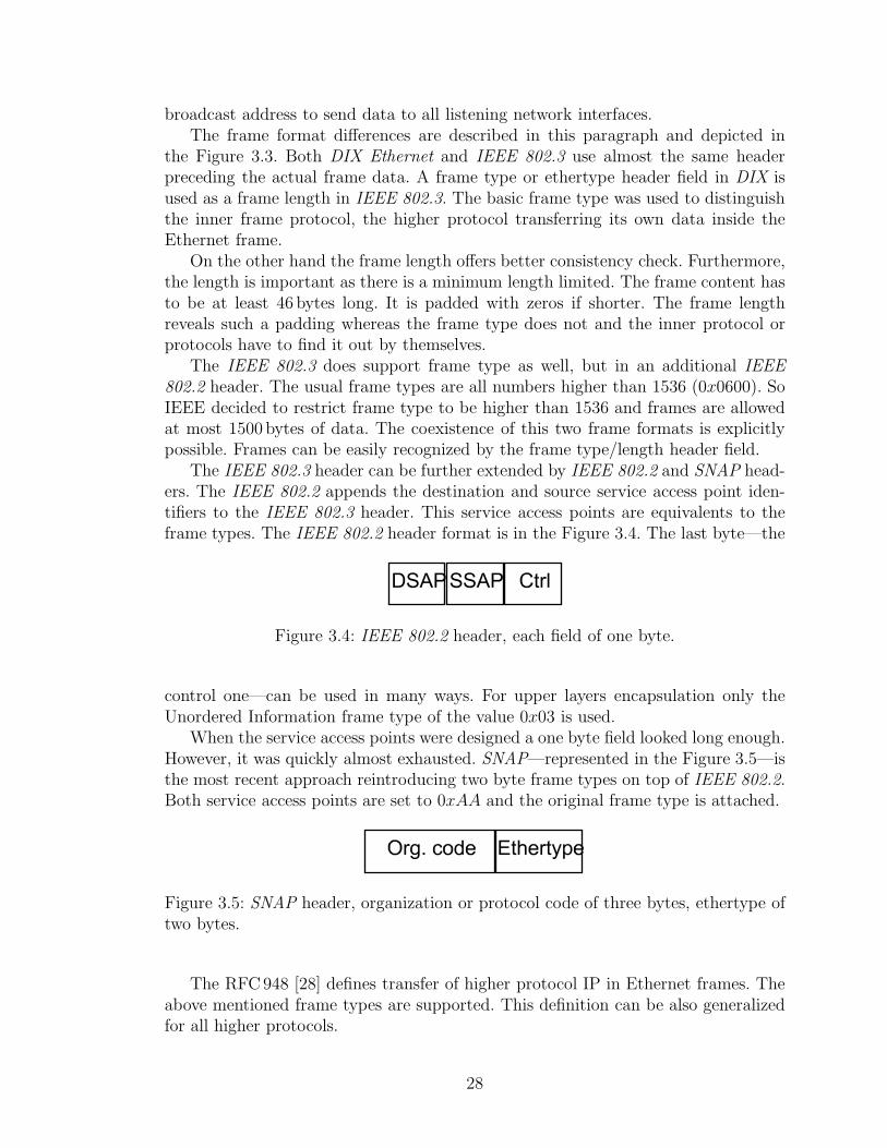
The IEEE 802.3 header can be further extended by IEEE 802.2 and SNAP head-ers. The IEEE 802.2 appends the destination and source service access point iden-tifiers to the IEEE 802.3 header. This service access points are equivalents to theframe types. The IEEE 802.2 header format is in the Figure 3.4. The last byte—the
Figure 3.4: IEEE 802.2 header, each field of one byte.
control one—can be used in many ways. For upper layers encapsulation only theUnordered Information frame type of the value 0x03 is used.
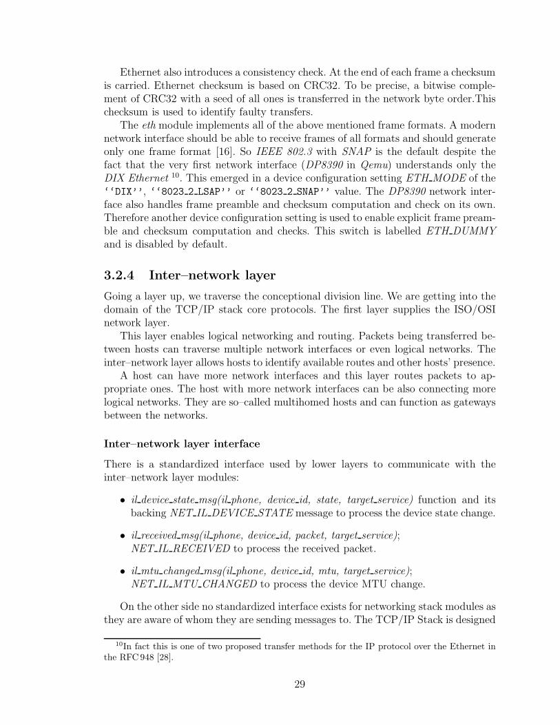
When the service access points were designed a one byte field looked long enough.However, it was quickly almost exhausted. SNAP—represented in the Figure 3.5—isthe most recent approach reintroducing two byte frame types on top of IEEE 802.2.Both service access points are set to 0xAA and the original frame type is attached.
Figure 3.5: SNAP header, organization or protocol code of three bytes, ethertype oftwo bytes.
The RFC948 [28] defines transfer of higher protocol IP in Ethernet frames. Theabove mentioned frame types are supported. This definition can be also generalizedfor all higher protocols.
28
Ethernet also introduces a consistency check. At the end of each frame a checksumis carried. Ethernet checksum is based on CRC32. To be precise, a bitwise comple-ment of CRC32 with a seed of all ones is transferred in the network byte order.Thischecksum is used to identify faulty transfers.
The eth module implements all of the above mentioned frame formats. A modernnetwork interface should be able to receive frames of all formats and should generateonly one frame format [16]. So IEEE 802.3 with SNAP is the default despite thefact that the very first network interface (DP8390 in Qemu) understands only theDIX Ethernet 10. This emerged in a device configuration setting ETH MODE of the‘‘DIX’’, ‘‘8023 2 LSAP’’ or ‘‘8023 2 SNAP’’ value. The DP8390 network inter-face also handles frame preamble and checksum computation and check on its own.Therefore another device configuration setting is used to enable explicit frame pream-ble and checksum computation and checks. This switch is labelled ETH DUMMYand is disabled by default.
3.2.4 Inter–network layer
Going a layer up, we traverse the conceptional division line. We are getting into thedomain of the TCP/IP stack core protocols. The first layer supplies the ISO/OSInetwork layer.
This layer enables logical networking and routing. Packets being transferred be-tween hosts can traverse multiple network interfaces or even logical networks. Theinter–network layer allows hosts to identify available routes and other hosts’ presence.
A host can have more network interfaces and this layer routes packets to ap-propriate ones. The host with more network interfaces can be also connecting morelogical networks. They are so–called multihomed hosts and can function as gatewaysbetween the networks.
Inter–network layer interface
There is a standardized interface used by lower layers to communicate with theinter–network layer modules:
• il device state msg(il phone, device id, state, target service) function and itsbacking NET IL DEVICE STATE message to process the device state change.
• il received msg(il phone, device id, packet, target service);NET IL RECEIVED to process the received packet.
• il mtu changed msg(il phone, device id, mtu, target service);NET IL MTU CHANGED to process the device MTU change.
On the other side no standardized interface exists for networking stack modules asthey are aware of whom they are sending messages to. The TCP/IP Stack is designed
10In fact this is one of two proposed transfer methods for the IP protocol over the Ethernet inthe RFC 948 [28].
29
to function with a concrete protocol in the inter–network layer, the IP protocol. Sothe upper layer modules do know exactly who is underneath.
Address Resolution Protocol - arp
As the TCP/IP stack communicates with hosts according to their logical IP ad-dresses, lower layers do not understand them and the addresses have to be translated.The ARP protocol provides this service. The protocol is defined in the RFC826 [21].It is a universal protocol translating addresses to and from many protocols.
If an address translation is not already known a discovery request packet is sent toall connected hosts. ARP uses a variable length packet where appropriate hardwareand logical address spaces are allocated for both the source and the destinationhost 11. The destination hardware address is unknown and left empty. The hardwarebroadcast address is used as the destination address of the packet so other hosts’network interfaces receive the request.If the host recognizes its logical address a replywith all addresses filled is sent back to the request source.
ARP implementations cache translations for further use. If an error occurs—packets do not get delivered or the host unreachable notification is received—thecached translation should be cleared.
A timeout would be also an option. However, there is a bit of inefficiency. Ifa host is present, the timeout clears the mapping and the broadcast query needs tobe send and replied. This puts unnecessary load to all connected hosts frequently.It can also lead to flooding in a big network. However, the timeout helps to discardunused entries and to propagate dynamic network changes.
On the other hand if a packet gets lost or an error is reported, the mapping iscleared and the packet can be resend. This involves the broadcast request as well,however, the caused load is unavoidable in order to recover from the error.
Although there is only the arp module present in the stack, some other can beadded later. The particular ARP module can be specified via the device configurationARP setting. This device specific setting is passed to the relevant inter–network layermodule. That module should respect the ARP configuration and use the proposedARP module.
ARP interface The address resolution protocol modules should offer the followinginterface:
• arp clean cache req(arp phone) function and its backingNET ARP CLEAN CACHE message to clear whole cache.
• arp clear address req(arp phone, device id, protocol service, address);NET ARP CLEAR ADDRESS to clear the device protocol address transla-tion.
11In case of IP and Ethernet the logical address has four bytes whereas the hardware has sixbytes.
30
• arp clear device req(arp phone, device id); NET ARP CLEAR DEVICEto clear the device cache.
• arp connect module(arp service); IPC M CONNECT ME TOto connect to the arp module returning the connection phone.
• arp device req(arp phone, device id, protocol service, netif service, address)NET ARP DEVICE message to register the arp module for the device at thedriver and to save the requesting protocol logical address.
• arp task get id() returning the task identifier if called in the bundle module.
• arp translate req(arp phone, device id, protocol service, address, translation,data); NET ARP TRANSLATE to translate the protocol address to the hard-ware address.
Internet Protocol - ip
The central protocol of the suite is the Internet Protocol. The IP protocol version 4 isdefined in the RFC791 [18] by DARPA from 1981. This protocol provides best–effortpacket transfers. It tries to do its best to deliver packets to other hosts.
The fourth version is the first widely deployed version. There is a newer IP ver-sion 6. This version introduces longer addresses, extended addressing and routing,mobility, and IPsec. Implementation of this version could be a topic of another mas-ter thesis. The still used and simpler version 4 is implemented in this one instead.
IP addressing Hosts are identified by their IP addresses. Each address falls intoan IP network. The address prefix of certain length is the network. The IPv4 uses fourbyte addresses and networks are assigned by IANA. There are groups of networkswith fixed number of bits where the very first few bits of an address determine thenetwork group. The textual addresses are written as four decimal numbers separatedby dots.
The four byte addresses might have been enough for the world—it is 4 294 967 296addresses, more than 4 billions—but not the network groups. An organization willingto have all its computers in its own network has to request a network. The networkis assigned from the smallest group the computer count fits in. As bits in the ad-dress cannot be divided, only sizes in multiples of two are available. The problemdeferred by using two special networks 192.168.0.* and 10.*.*.*. Anyone may usethese networks while not being directly connected to other networks, especially tothe Internet. Such networks are local and can be connected to other networks usinggateways.
Along with network groups there are also network masks. It is a bit more universalapproach. The address is divided into a network address and a host identifier. Themask contains ones at the network address places and zeros at the host identifier,respectively. A network can be divided into smaller parts if the mask sets more bits.
In order to communicate with others, a host has to maintain its routing table.The table contains entries where to send packets targeted to other hosts. Hosts of the
31
same network can be accessed (almost) directly but hosts of other networks not. Theinstitution of multihomed gateways is introduced for the latter case. The host can beconfigured to send packets to other network using a gateway. The gateway forwardsthat packets further to the proper network or another gateway. The gateway routingcan be set as a network and a netmask, where only the mask bits are compared to thetarget address. It can be less than the target network mask. Similar entries can begrouped together by shortening the mask. This is called the Classless Inter–DomainRouting.
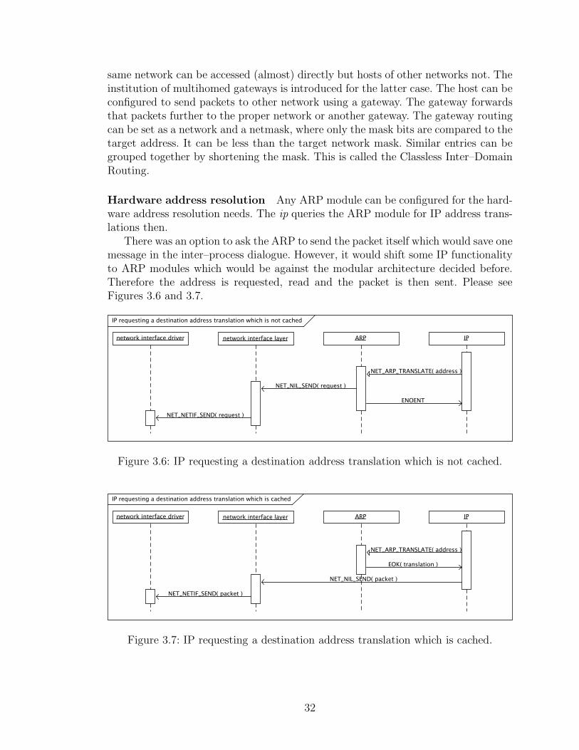
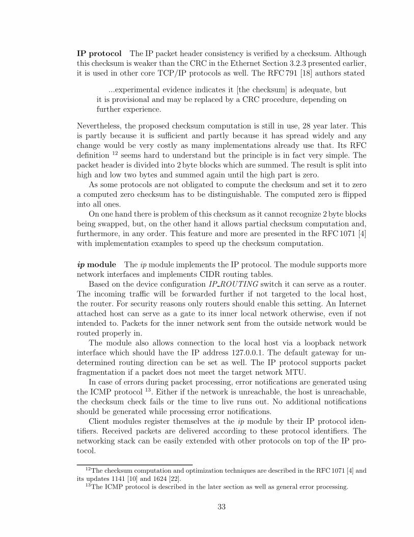
Hardware address resolution Any ARP module can be configured for the hard-ware address resolution needs. The ip queries the ARP module for IP address trans-lations then.
There was an option to ask the ARP to send the packet itself which would save onemessage in the inter–process dialogue. However, it would shift some IP functionalityto ARP modules which would be against the modular architecture decided before.Therefore the address is requested, read and the packet is then sent. Please seeFigures 3.6 and 3.7.
Figure 3.6: IP requesting a destination address translation which is not cached.
Figure 3.7: IP requesting a destination address translation which is cached.
32
IP protocol The IP packet header consistency is verified by a checksum. Althoughthis checksum is weaker than the CRC in the Ethernet Section 3.2.3 presented earlier,it is used in other core TCP/IP protocols as well. The RFC791 [18] authors stated
...experimental evidence indicates it [the checksum] is adequate, butit is provisional and may be replaced by a CRC procedure, depending onfurther experience.
Nevertheless, the proposed checksum computation is still in use, 28 year later. Thisis partly because it is sufficient and partly because it has spread widely and anychange would be very costly as many implementations already use that. Its RFCdefinition 12 seems hard to understand but the principle is in fact very simple. Thepacket header is divided into 2 byte blocks which are summed. The result is split intohigh and low two bytes and summed again until the high part is zero.
As some protocols are not obligated to compute the checksum and set it to zeroa computed zero checksum has to be distinguishable. The computed zero is flippedinto all ones.
On one hand there is problem of this checksum as it cannot recognize 2 byte blocksbeing swapped, but, on the other hand it allows partial checksum computation and,furthermore, in any order. This feature and more are presented in the RFC1071 [4]with implementation examples to speed up the checksum computation.
ip module The ip module implements the IP protocol. The module supports morenetwork interfaces and implements CIDR routing tables.
Based on the device configuration IP ROUTING switch it can serve as a router.The incoming traffic will be forwarded further if not targeted to the local host,the router. For security reasons only routers should enable this setting. An Internetattached host can serve as a gate to its inner local network otherwise, even if notintended to. Packets for the inner network sent from the outside network would berouted properly in.
The module also allows connection to the local host via a loopback networkinterface which should have the IP address 127.0.0.1. The default gateway for un-determined routing direction can be set as well. The IP protocol supports packetfragmentation if a packet does not meet the target network MTU.
In case of errors during packet processing, error notifications are generated usingthe ICMP protocol 13. Either if the network is unreachable, the host is unreachable,the checksum check fails or the time to live runs out. No additional notificationsshould be generated while processing error notifications.
Client modules register themselves at the ip module by their IP protocol iden-tifiers. Received packets are delivered according to these protocol identifiers. Thenetworking stack can be easily extended with other protocols on top of the IP pro-tocol.
12The checksum computation and optimization techniques are described in the RFC 1071 [4] andits updates 1141 [10] and 1624 [22].
13The ICMP protocol is described in the later section as well as general error processing.
33
IP interface The ip module uses more device configuration settings along with theARP and the IP ROUTING. First and most important is the IP CONFIG denot-ing ‘‘static’’ address configuration. No other value is supported yet as the net-working stack contains only core protocols and further would be necessary, namelyDHCP or at least BOOTP. For the static configuration the network interface addressIP ADDR, IP BROADCAST and IP GATEWAY addresses and IP NETMASK areread. They should be set to a textual IP addresses, ‘‘10.0.2.15’’ for example.
ip interface The ip module offers the following interface:
• ip add route req(ip phone, device id, address, netmask, gateway) function andits backing NET IP ADD ROUTE message to add a route entry for the device.
• ip bind service(ip service, protocol, calling service, receiving client connection,receiving callback); IPC M CONNECT TO ME to register itself as an upperprotocol, either the callback or the client connection function is used accordingto the build architecture.
• ip connect module(ip service) to connect to the ip module returning the con-nection phone.
• ip device req(ip phone, device id, netif service); NET IL DEVICE to registera device and its driver.
• ip get route req(ip phone, protocol, destination, address length, device id,pseudo header, header length); NET IP GET ROUTE to get a destination di-rection and pseudo header for sending.
• ip packet size req(ip phone, device id, addr len, prefix, content suffix);NET IL PACKET SPACE to read maximum packet dimensions, minimal ad-dress length, prefix and suffix and maximum content length in bytes.
• ip received error msg(ip phone, device id, packet, target service, error service);NET IP RECEIVED ERROR to announce a received error notification.
• ip send msq(ip phone, device id, packet, sender service, error service);NET IL SEND to send a packet (queue). A particular device can be specified.If the error service is set, no further errors are generated.
• ip set gateway req(ip phone, device id, gateway); NET IP SET GATEWAY toset the default gateway.
Internet Control Message Protocol - icmp
The ICMP protocol defined in the RFC792 [19] is a support protocol for the TCP/IPsuite protocols. It carries error notifications and diagnostic messages. If an erroroccurs an ICMP packet is created. It contains the beginning of the original packetstarting with the original IP header.
34
ICMP packets are sent via IP and there is a protocol number assigned for theICMP protocol as well. Therefore ICMP behaves in a similar way like upper protocolsin the transport layer. The icmp module registers at the ip module and received ICMPpackets are then delivered to the icmp. However, the ICMP protocol actually fallsinto the inter–network layer next to the IP protocol. It does not add extra logic asother protocols in the above layer.
The ICMP error reporting can be disabled by setting the global configurationICMP ERROR REPORTING switch to anything else than ‘‘yes’’.
The ICMP protocol offers more than just error notification. There is one highlydemanded functionality, the echo. One host sends an echo request to another hostand waits for a reply. If the other hosts is reached—and is not configured to blockICMP echo requests—the same packet is sent back as the echo reply. The packetscontain sequence numbers to match the replies with the previous requests. The ICMPecho replying can be disabled by the global configuration ICMP ECHO REPLYINGswitch. A local application is allowed to connect to the icmp module and call theecho process.
The ICMP protocol client application can use the interface:
• icmp connect module(icmp service) function and its backingIPC M CONNECT ME TO message to connect to the icmp module returningthe connection phone.
• icmp echo msg(icmp phone, message size, timeout, ttl, tos, dont fragment, ad-dress, address length); NET ICMP ECHO to ping a host.
icmp interface The icmp module offers the following interface:
• icmp connect module(icmp service); IPC M CONNECT ME TO to connect tothe icmp module returning the connection phone.
• icmp destination unreachable msg(icmp phone, code, mtu, packet);NET ICMP DEST UNREACH to report the destination unreachable error.
• icmp parameter problem msg(icmp phone, code, pointer, packet);NET ICMP PARAMETERPROB to report the parameter problem error.
• icmp source quench msg(icmp phone, packet);NET ICMP SOURCE QUENCH to report the source quench error.
• icmp time exceeded msg(icmp phone, code, packet);NET ICMP TIME EXCEEDED to report the time exceeded error.
3.2.5 Transport layer
Although the IP protocol offers host to host communication this is not enough. Thenext layer, the transport layer, enables more host connections to run parallel.
35

Every connection or connection–less transfer uses ports. The host address, pro-tocol and port determines the communication source or destination. This triplet iscalled a half–socket. The other side is also identified by a half–socket, both togethercreating the socket. The socket is used to identify the communication.
Client application create and hold such half–sockets. The client part of the art isdescribed in the next Section 3.2.6.
Transport layer protocols have to register themselves at the ip module with theirIP protocol number. After that they can use the ip interface and consume theirreceived packets. They can also use the ICMP protocol if desired.
The transport layer is the topmost layer of the networking stack. Client appli-cations are directly connected to modules of this layer using the—later described—socket library.
As this is the last layer of the stack no packets are allowed to go any further.Client application data have to be copied to and from their address space from andinto packets.
Transport layer interface
There is a standardized interface used by lower layers to communicate with thetransport layer modules:
• tl received msg(il phone, device id, packet, target service, error service) func-tion and its backing NET TL RECEIVED message to process the receivedpacket. Either the registered function or the IPC message is used.
Internet Control Message Protocol - icmp
As the ICMP protocol falls into the inter–network layer in fact it is described therein the Section 3.2.4 earlier. It supports the general transport layer interface.
User Datagram Protocol - udp
The User Datagram Protocol is the simplest transport layer protocol. It is describedin the RFC768 [17] and does not add any other functionality to the underlying IPprotocol but sockets. Client applications are offered the state–less and best–effortcommunication. Data can get lost, arrive out–of–order or more than once.
The module can be configured to compute checksums for outgoing packets. Thesame checksum as in IP is used except that it spans the IP pseudo header, the UDPheader and the data as well. The IP header is included in the checksum to identifymisrouted datagrams and the UDP header and data are included to verify theirconsistency. The checksum is optional but highly recommended. The UDP checksumglobal configuration switch is called UDP CHECKSUM COMPUTING.
The UDP protocol is a state–less protocol so it can be viewed as half–socketscommunicating with each other. An application can send data to anyone and receivedata from anyone. The application has to provide the destination identification, the
36
address and the port. With a received packet the source address and port are alwaysprovided with the packet data.
Although it can be desired to just send data and not receiving any, the defaultis not to. The module assigns a listening port automatically on send if not alreadyassigned. This behaviour can be changed using the UDP AUTOBINDING globalconfiguration switch.
Transmission Control Protocol - tcp
The second transport layer protocol is much more powerful. The TCP protocol es-tablishes reliable communication between two hosts and ensures data transfers. Bothsides cooperate to deliver all data exactly once and in the right order.
The hosts establish the connection first. One side listens and waits for an incomingconnection as the other one initiates the connection. Similar dialogue happens at theend of the connection.
Transferred data are acknowledged when received in the next outgoing or a sep-arate packet. Packets are retransmitted if not acknowledged within a specific time.The TCP protocol uses the same consistency checksum as the UDP protocol. Thetcp module contains much more logic maintaining socket states and buffering data.The comprehensive description of the TCP protocol can be studied in the work ofZaghal and Khan [30].
There exist many extensions on top of the original RFC793 [20]. To name someof them: congestion detection and avoidance, MD5 checksum, slow start, fast re-transmit, selective acknowledgement, adaptable retransmission timers etc. Many areenhancements, optimizations or security improvements.
3.2.6 Application programming interface - libsocket
There is a client library for client applications willing to use the networking capa-bilities of the system. A standardized—in the right meaning—API does not exist.However, the BSD Unix operating system came up with a networking client designin the release 4.2BSD in 1983. Its application programming interface became a defacto standard soon and is called the Berkeley socket interface [11].
The client library implements core functions of the Berkeley socket interface.This fulfils networking needs and eases porting of networking applications. The li-brary maintains local sockets and connections to needed transport layer modulesand registers its own client connection function to process messages sent by thesemodules. All this is transparent to the client application.
libsocket interface The libsocket library offers the following interface:
• accept(socket id, address, address length) and its internalNET SOCKET ACCEPT message to get an accepted socket and the remotehost identification.
37
• bind(socket id, address, address length); NET SOCKET BINDto bind the socket to a local port for listening.
• closesocket(socket id); NET SOCKET CLOSE to close the socket. This func-tion behaves like the original close() but differs in the name as the name isused in HelenOS for file operations.
• connect(socket id, address, address length);NET SOCKET CONNECT to connect to the remote host.
• getsockopt(socket id, level, name, value); NET SOCKET GETSOCKOPT toget the socket option value.
• listen(socket id, backlog); NET SOCKET LISTEN to set the maximum numberof waiting accepted sockets.
• recv(socket id, data, length, flags); NET SOCKET RECV to receive the datavia the connected socket.
• recvfrom(socket id, data, length, flags, address, address length);NET SOCKET RECVFROM to receive the data and the remote host identi-fication via the listening socket.
• send(socket id, data, length, flags); NET SOCKET SEND to send the data viathe connected socket.
• sendto(socket id, data, length, flags, address, address length);NET SOCKET SENDTO to send the data via the socket.
• setsockopt(socket id, level, name, value); NET SOCKET SETSOCKOPT toset the socket option value.
• socket(domain, type, protocol); NET SOCKET to create a new socket.
All the functions except the closesocket() are blocking—do not return until com-pleted.
3.2.7 Applications
To demonstrate the operational networking stack a few applications were imple-mented. The both presented are common part of operating systems with networkingstacks.
Ping - ping
The first application’s purpose is to test if the networking stack is operational. It testswhether a host is reachable by sending an ICMP echo message. If testing the local-host address ‘‘127.0.0.1’’ the loopback network interface is checked. If configured
38

correctly the icmp module sends, replies and receives the echo message reporting suc-cess. If testing another host’s address the real network interface is checked instead.The icmp reports success if a reply to the sent request is received. The applicationprints the overall time taken in both cases.
Echo - echo
The second application listens at a specified port and echoes back what it receives.The application prints the received data and the source address and port.
39
Chapter 4
Discussion
4.1 Implementation
The implementation follows the networking stack design from the previous sectionsto fulfil the TCP/IP stack needs. In this section implementation details and opti-mizations are described. This part is rather brief and technical.
4.1.1 HelenOS internals
Some HelenOS specific implementation details are mentioned in this section. Theseare only relevant fragments of the concept of the system from the networking stackpoint of view.
Services A name server module where all tasks can register their services them-selves is used in HelenOS. The concept can be looked at as a service oriented oper-ating system where any task can be a service. Even more services. They are used assystem unique identifiers of the module capabilities.
Other modules can query the name server if they are looking for a particularservice. The name server redirects them to the registered module if there is such.
This gives another layer of abstraction and allows indirect task connections, wherethe querying task does not know which task it needs to connect to.
The networking stack modules are registered as such services as well. The servicesare defined in the uspace/lib/libc/include/ipc/services.h header file in theHelenOS source directory.
Parallelism If a module wants to process multiple connections as in our casealmost everywhere in the stack, an asynchronous manager provided in HelenOS servesthe best. Module starts in one fibril in one thread and calls the async manager()function after initialization. This function starts the asynchronous manager and runsfurther in the fibril. There is a new fibril created for each incoming connection. Dueto this fact many fibrils can be present in the service (server–like) modules.
40
Device numbers Devices in HelenOS should be assigned a device identifier. Thisidentifier enables a system–unique identification of the device. The identifier is gen-erated in the kernel via a system call device assign devno(). The system unambiguityof the identifiers can be achieved only in the kernel.
Network interfaces are devices as well and therefore the networking stack re-quests an identifier for each present. Modules in the stack refer to them using theseidentifiers.
The central configuration module is able to assign a virtual device number tothe present network interfaces. These identifiers would be networking unique butnot system unique which could lead to confusion. Furthermore, the usage of theprovided system call complies with the system designers’ attitude.
4.1.2 Support structures
A few structures to support the development are going to be introduced. Some ofthem are template–like data structures for use with any data types. There are simplecontainers to fulfil basic needs of the networking stack in its first version as it is morea prototype rather than a tuned–up performance–optimized stack.
packet structure
The packet is a memory block with a header at the beginning and a data containerafterwards. This memory block is aligned to the address page size. Packets are alsoextended to carry their addresses to ease inter–process communication. Modules canuse packet address containers to pass addresses. The packet is designed as a shareablememory block with the header containing:
• The packet identifier, the unique packet identifier assigned by the packet server,
• The packet queue placement, packet queue sort order and metric as well asprevious and next packet identifiers,
• The packet length in bytes, the overall packet structure and data containersize,
• The packet source and destination addresses, universal space for passing ad-dresses with the packet between modules, they are stored right after the packetheader and the data container starts after them,
• The addresses length, the actual length of the stored addresses,
• The prefix reserved bytes, the number of reserved bytes before the applicationdata,
• The data reserved bytes, the number of reserved bytes after the applicationdata,
41
• The data start offset, the actual data start to be used at the next processingstep,
• The data end offset, the actual data end to be used at the next processing step,and
• The data container.
The packet header structure is defined in the structures/packet/packet header.h
header file. Only the packet server and the packet client library should include anduse it. There is only masked packet pointer definition for client modules packet t.
Packet server
The packet server is the central authority of the packet management system. Onlyone module in the networking stack should implement it. Its implementation is inthe structures/packet/packet server.c source file. The hosting module shouldbe the first and the last running of the whole stack and has to forward all packetmessages to the packet server message() function. The packet messages are definedin the structures/packet/packet messages.h header file. New packets are createdwith the view of memory sharing. Therefore the requested size is rounded up to theaddress page. The task receiving a memory block always allocates whole addresspages anyway. So the packet uses as much space as possible which does not onlydecrease overhead but also eases packet reuse.
The packet server keeps released packets in queues according to their total size.There are seven sorted queues to distribute free packets. The first one containspackets up to one address page size. The second up to two address pages size and soon exponentially. Packet is inserted to the lowest queue it fits in. New packet requestsare primary served from this queues. The best fit and last recently used algorithm isused which tries not to waste resources and to avoid frequent TLB page faults. Thequeues are sorted and searched from the first of a sufficient packet size. If no freepacket is found a new one is created. If an old packet is reused it is probable that atleast some of the processing modules have already used it. If they have, they havegot it shared in their address space. Therefore the packet server might not be queriedto share the packet at all. The older the packet is the higher is the probability.
Packet library
Every packet management system client module needs to use the packet library.This library takes care of packet mapping, requesting from and releasing to theserver transparently. The client module has to provide only the packet server phone.The library also offers functions to manipulate packets such as:
• Set and get packet addresses, variable memory blocks up to the reserved addresssize,
• Copy data into the container,
42
• Prefix and suffix data returning a pointer to the new area allocated,
• Queue and detach a packet to and from a packet queue, and
• Traverse a packet queue.
For the packet mapping a global data structure is used. It is an integer to pointermap with a safety lock. As packets are numbered in the ascending order startingfrom one and are not released until the module terminates, only a simple map isused. The map is created at the module start and keeps filling up with time. It neverreleases a packet mapping until destroyed. Mappings are divided into pages of onehundred identifiers each. So the actual mapping position may be obtained instantly(in the O(1) time) using the following macros:
/** Packet map page size.
*/
PACKET_MAP_SIZE 100
/** Returns the packet map page index.
* @param packet_id The packet identifier.
*/
PACKET_MAP_PAGE(packet_id) \
(((packet_id) - 1) / PACKET_MAP_SIZE)
/** Returns the packet index in the corresponding packet map page.
* @param packet_id The packet identifier.
*/
PACKET_MAP_INDEX(packet_id) \
(((packet_id) - 1) % PACKET_MAP_SIZE)
The map pages are allocated only if needed as the total number of packets in thesystem is variable and is not distributed to all modules. If the packet map is destroyedit releases all the mapped packets. The packet server itself is also a packet clientbecause it needs the packet mapping as well to remember all the existing packets.The only difference is that the packet server inserts the mapping itself and does notquery anyone.
The last optimization is queuing packets. Modules are able to send the wholequeue as if it were only one packet. If possible a packet queue is the preferred wayas it decreases processing overhead.
Measured strings
Another inter–process communication structure is a measured character string. Thisis a universal structure containing a character string pointer and its length. Thestructure is the measured string header and the actual string is the measured stringdata. The structure is used universally for any type of memory block not just thecharacter string. Its purpose is to transfer large data blocks between modules.
43
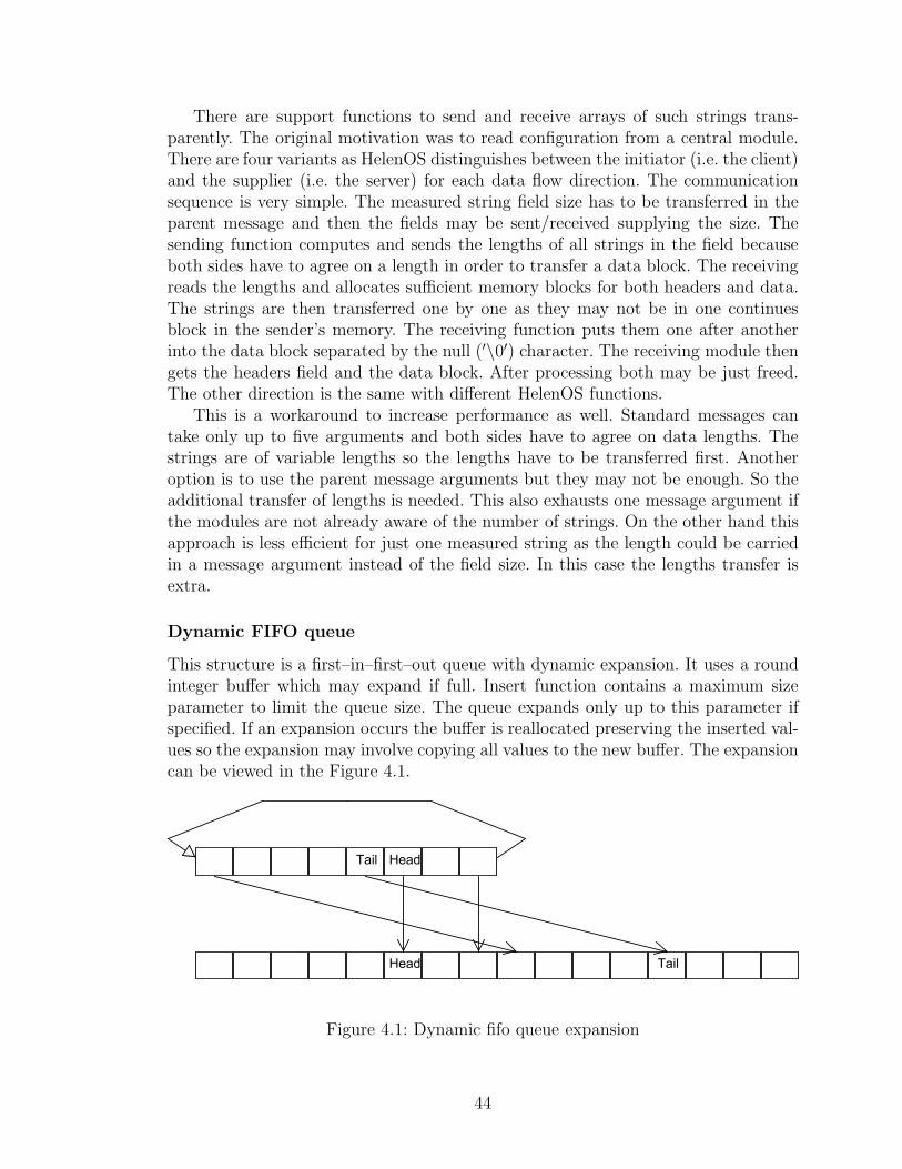
There are support functions to send and receive arrays of such strings trans-parently. The original motivation was to read configuration from a central module.There are four variants as HelenOS distinguishes between the initiator (i.e. the client)and the supplier (i.e. the server) for each data flow direction. The communicationsequence is very simple. The measured string field size has to be transferred in theparent message and then the fields may be sent/received supplying the size. Thesending function computes and sends the lengths of all strings in the field becauseboth sides have to agree on a length in order to transfer a data block. The receivingreads the lengths and allocates sufficient memory blocks for both headers and data.The strings are then transferred one by one as they may not be in one continuesblock in the sender’s memory. The receiving function puts them one after anotherinto the data block separated by the null (′\0′) character. The receiving module thengets the headers field and the data block. After processing both may be just freed.The other direction is the same with different HelenOS functions.
This is a workaround to increase performance as well. Standard messages cantake only up to five arguments and both sides have to agree on data lengths. Thestrings are of variable lengths so the lengths have to be transferred first. Anotheroption is to use the parent message arguments but they may not be enough. So theadditional transfer of lengths is needed. This also exhausts one message argument ifthe modules are not already aware of the number of strings. On the other hand thisapproach is less efficient for just one measured string as the length could be carriedin a message argument instead of the field size. In this case the lengths transfer isextra.
Dynamic FIFO queue
This structure is a first–in–first–out queue with dynamic expansion. It uses a roundinteger buffer which may expand if full. Insert function contains a maximum sizeparameter to limit the queue size. The queue expands only up to this parameter ifspecified. If an expansion occurs the buffer is reallocated preserving the inserted val-ues so the expansion may involve copying all values to the new buffer. The expansioncan be viewed in the Figure 4.1.
Figure 4.1: Dynamic fifo queue expansion
44
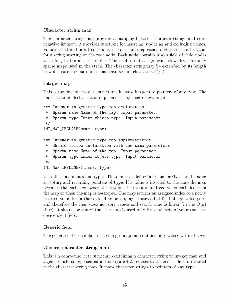
Character string map
The character string map provides a mapping between character strings and non–negative integers. It provides functions for inserting, updating and excluding values.Values are stored in a tree structure. Each node represents a character and a valuefor a string starting at the root node. Each node contains also a field of child nodesaccording to the next character. The field is not a significant slow down for onlysparse maps used in the stack. The character string may be extended by its lengthin which case the map functions traverse null characters (′\0′).
Integer map
This is the first macro data structure. It maps integers to pointers of any type. Themap has to be declared and implemented by a set of two macros
/** Integer to generic type map declaration.
* @param name Name of the map. Input parameter.
* @param type Inner object type. Input parameter
*/
INT_MAP_DECLARE(name, type)
/** Integer to generic type map implementation.
* Should follow declaration with the same parameters.
* @param name Name of the map. Input parameter.
* @param type Inner object type. Input parameter
*/
INT_MAP_IMPLEMENT(name, type)
with the same names and types. These macros define functions prefixed by the name
accepting and returning pointers of type. If a value is inserted to the map the mapbecomes the exclusive owner of the value. The values are freed when excluded fromthe map or when the map is destroyed. The map returns an assigned index to a newlyinserted value for further extending or looping. It uses a flat field of key–value pairsand therefore the map does not sort values and search time is linear (in the O(n)time). It should be stated that the map is used only for small sets of values such asdevice identifiers.
Generic field
The generic field is similar to the integer map but contains only values without keys.
Generic character string map
This is a compound data structure containing a character string to integer map anda generic field as represented in the Figure 4.2. Indexes to the generic field are storedin the character string map. It maps character strings to pointers of any type.
45
Figure 4.2: Generic character map
Module map
The module map serves as a container to store information about networking mod-ules. It is a generic character map to a module structure containing a task identifier,a service identification, a module message phone, an optional usage counter, modulename and filename and a module connection function. The purpose of the map is tounify a service modules’ usage. A module fills the map with possible service modulesit can use at the startup. The module calls a function to retrieve a running servicemodule later. The map checks if an entry exists, if the module is running1 and if themodule is connected 2. If not it starts (spawns) the module and/or connects to ittransparently.
4.1.3 Modules
The networking stack modules’ implementation details are described in this section.The programming documentation is in the doc/ directory generated by Doxygenusing JavaDoc style comments. The general module concept is described first.
Module design
The networking stack was decided to support both modular and monolithic compila-tion. The networking stack architecture can be set by the compile–time configurationoption called Networking architecture.
Each service module has to implement handling of client connections, processingof IPC messages and its public interface and specific core functions. While the bundlemodule implements handling of client connections, processing of all IPC messagesand public interfaces and specific core functions of all its modules. Therefore thestack modules are compounds of many parts in order to support both modular andmonolithic build.
The module parts are located in separate source files to avoid any architecturespecific source code variants. Furthermore, the source code is distributed into manysmaller functional units which reduces the code complexity. For a visual representa-tion of the module parts assembly see the Figure 4.3. The module parts interactionin UML diagrams the appendix Section B.2.
1The task identifier would be zero.2The phone would be zero.
46
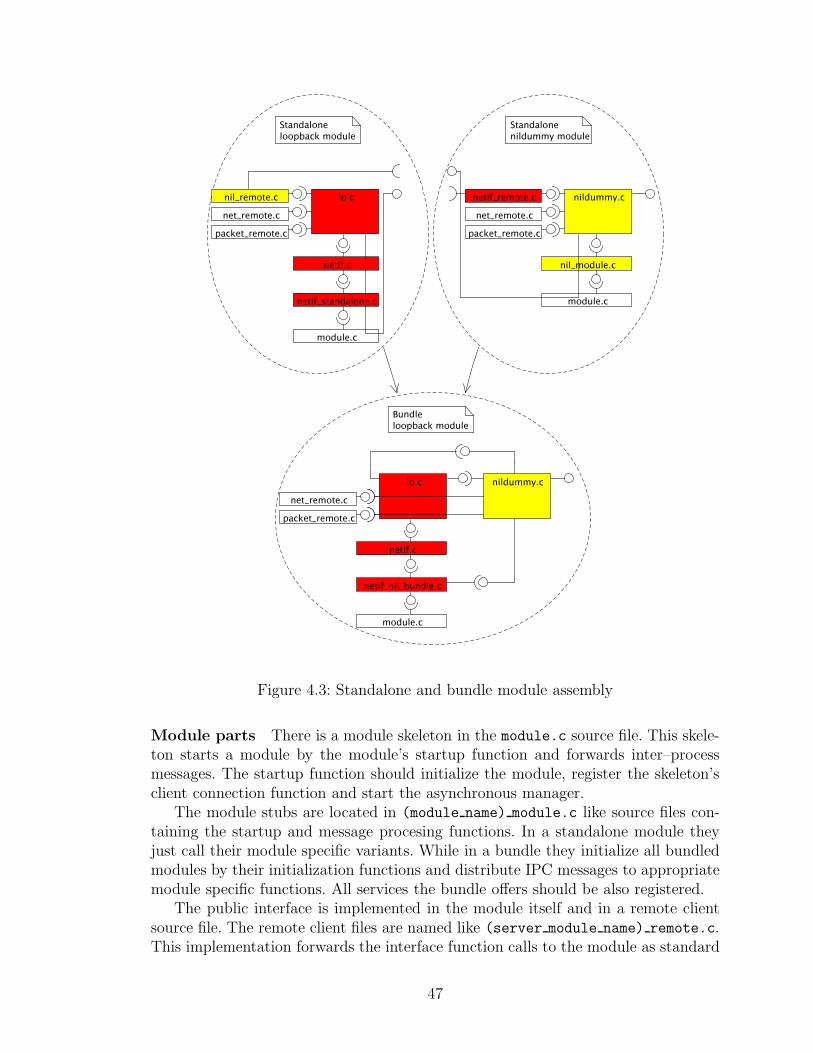
Figure 4.3: Standalone and bundle module assembly
Module parts There is a module skeleton in the module.c source file. This skele-ton starts a module by the module’s startup function and forwards inter–processmessages. The startup function should initialize the module, register the skeleton’sclient connection function and start the asynchronous manager.
The module stubs are located in (module name) module.c like source files con-taining the startup and message procesing functions. In a standalone module theyjust call their module specific variants. While in a bundle they initialize all bundledmodules by their initialization functions and distribute IPC messages to appropriatemodule specific functions. All services the bundle offers should be also registered.
The public interface is implemented in the module itself and in a remote clientsource file. The remote client files are named like (server module name) remote.c.This implementation forwards the interface function calls to the module as standard
47
IPC messages. In order to use the interface all client modules have to be built in thebundle with the module or standalone with the remote file.
Interfaces and public constants are located in the include/ directory. Some moreoften used interface functions are statically defined in the messages.h header file.
As the networking stack can be built as one big module, the message destinationhas to be uniquely specified. All bundled modules share the same connections so thetarget service is added as one of the message arguments. According to this argumentthe real destination module in the bundle can be identified.
The module core implementation source file (module name).c contains the mod-ule specific startup and message processing functions, the public interface imple-mentation and the specific core functions. The message processing function mapsthe public interface to the internal interface or core functions. This means that thereare in fact two entry points for each inteface function, a message from the messageprocessing function and a direct interface function call.
Compilation As there are no architecture specific source code variants in separatefunctional units, the compilation was designed to build each source file at most once.Object files .o representing .c source files are created and the target architecture isachieved while linking built object files together and assembling modules.
If a module is built as a standalone the skeleton and this module stub files have tobe included. If it is a part of a larger module, only the module core implementationsource file is used. The main module’s bundle startup file and the skeleton file areincluded.
When the other build architecture is chosen no files have to be rebuild whichincreases the compilation performance. Only the object files are assembled in a dif-ferent way into proper modules.
Built modules are then transferred into the /srv/ directory in the HelenOS bootimage.
Packet/packet queue processing
In this section we describe the general concept of packet passing. Although the packetand packet queues are interchangeable they can have different meanings.
Network interface The network interface driver can send packet queues. Thepackets are transmitted one by one. On the other hand the received packets can bebuffered and sent as a packet queue to the network interface layer module.
Network interface layer Packet queues can be passed to the network interfacemodules from both directions. Each packet means exactly one frame. They are pro-cessed and can be forwarded as packet queues as well.
Inter–network layer The arp module can receive packet queues and processesthe packets one by one.
48
The ip module is designed to process received packets or packet queues sepa-rately. Due to the possible fragmentation and the attempt to minimize data copying,a fragmented packet is stored as a packet queue containing the packet fragments.Therefore if a packet queue is transferred to the upper layer, it is also only “one”packet. On the other side packet queues from the upper layer have to be fragmentsof one large packet as well. This is an optional optimization described in the nextsection.
Transport layer Client application data have to be copied to and from theiraddress space from and into packets. Data copying is an expensive operation, talkingabout both time and resources. With this taken into account an optimizing approachis designed.
If a packet is received its size in the number of packets (fragments) is sent to theappropriate application. When the application initiates the data read, block of datais continuously read from the packet fragments.
On the other side the transport layer module can specify maximum data fragmentsize. When the client application initiates the data write, data are written in blocksof this size. The transport layer module writes these blocks right into packets.
The fragment size can be the maximum protocol data length. Such packets canget fragmented later which would involve data copying. If the module is aware ofthe network interface’s MTU and subtracts necessary prefix and suffix lengths, greatsavings can be obtained. The application data get copied right into packet fragmentswhich will be passed through the stack without any more copying.
net
The networking stack configuration is static for each of the stack architectures. Theconfiguration is in the source code as HelenOS did not have file operations support.File operations and disk image mapping are young features in HelenOS and are notused by the stack so far. The general design decision about configuration files inHelenOS is not made yet.
The module source is located in the uspace/srv/net/net sub directory of theHelenOS source directory. There are two stack architecture specific source files,net standalone.c for the modular and net bundle.c for the monolithic build.
Network interface driver
Architecture The driver module is designed as a skeleton and a stub implementingdevice specific routines. The reason to do it like this is that this universal driver designallows bundle build with any of the network interface layer modules. Furthermore,the driver is the main module in the bundle.
The skeleton is located in the netif/netif.c source file and uses the generalmodule skeleton source file module.c. The driver stub implements an interface de-fined in the netif/netif module.h header file bacause the network interface skele-ton forwards messages to these functions. The skeleton provides some common func-
49
tionality like message handling (not processing), keeping device information, safetylocking, module initialization and packet mapping and releasing.
Device states Device states are defined as device state t. A device is enabled inthe NETIF ACTIVE state. Device drivers might be, but should not be, started atthe boot. They should be started by the net module on demand which saves someresources until needed.
Usage statistics Network interface usage statistics are provided in a form of thenet device stats structure.
IRQ An IRQ recognition command sequence can be registered in the kernel. Onlya small set of safe commands 3 is used. This sequence is run by the kernel if aninterrupt occurs. It should check its device state and accept the interrupt if causedby the device. The kernel then calls the user space callback function. An example isin the DP8390D section later.
lo bundle The networking module attaches the loopback driver to a dummy net-work interface layer module. The nildummy module just passes all messages to andfrom the driver. Therefore it is much more efficient to combine networking inter-face layer and driver capabilities into one module and save a bit of inter–processcommunication and system resources. There is support for a separate module aswell as a bundle module. In a productive system the bundle loopback module isrecommended as it lowers both the overhead and resources.
dp8390 Although the chosen chip DP8390D is well documented writing a driverfrom scratch is out of the scope of this work. Furthermore a real hardware is neededat least at the final stage of the driver development as simulators’ functionality canslightly differ. Both reasons lead to porting an existing driver from other systems.
There are not many drivers under a suitable licence 4. The Linux network interfacedriver design is a bit complicated as it spans over many source files. On the otherhand Minix does not support so many network interfaces and drivers are easilyrecognizable. On top of that Minix uses the same licensing as HelenOS does so theMinix driver was taken and ported into HelenOS. The Minix driver uses four probingfunctions to support the four most common clones of the basic NE2000, however,only the original NE2000 was ported.
There are only a few settings the NE2000 ISA card allows and the Qemu card islocated at the address 0x300 and uses IRQ9.
In order to map an address space of a device into the task’s address space thepio enable() system call is used. With this function a device driver is able to directly
3IRQ commands are defined as irq cmd type in the kernel/generic/include/ddi/IRQ.h filein the HelenOS source directory.
4Only a few licences allow (almost) free usage and distribution. HelenOS is under the BSDlicence.
50
control its device registers. The probe function is called next to verify the rightdevice’s presence.
When the device is started an IRQ handler has to be registered via the systemcall ipc register irq(). This function registers the IRQ recognition command sequenceand a callback function. The command sequence is run in the kernel whenever aninterrupt occurs. For the DP8390 the following sequence is used:
1. CMD PIO READ 8 reading an interrupt status register,
2. CMD PREDICATE skipping the next command if the read value is zero, and
3. CMD ACCEPT accepting the interrupt, if not skipped.
When the interrupt is accepted the kernel sends an IPC notification which callsthe callback function. The interrupt recognition command sequences are run in thekernel mode with interrupts disabled whereas the callback function runs in the userspace mode with interrupts enabled again. When an interrupt occurs there can bemore devices using the same interrupt number and therefore they have to check if itis really their interrupt being processed.
This shows that only the recognition command sequence is run in the privilegedmode. The kernel checks the proposed command sequence and referred addresseswhile registering it. This driver is a true user space driver as none of its code 5 runsin the kernel mode.
The driver module in the netif/dp8390/dp8390 module.c source file is writtento provide a solid base for other network interface drivers. There is the networkinterface stub interface and the interrupt handler implemented. The ported networkinterface core functions in the netif/dp8390.c source file are accessed via a specificinterface in the netif/dp8390 drv.h header file.
Network interface layer
Interfaces The nil/nil remote.c source file contains functions called only bydrivers whereas the upper stack has to send IPC messages in all cases. As the upperstack interface is based on common message functions defined in the messages.h
header file, no additional ... remote.c file is needed.
Bundle within a network interface driver The network interface layer modulecan be built bundled within the network interface driver module. The driver is themain module and hence should initialize the network interface layer core at thestartup. The driver registers itself, not the network interface layer service, and theupper stack should connect directly to it. This is due to the lack of the universalnetwork interface layer functionality as the bundle cannot function with anotherdriver except the bundled one. So the networking stack has to be configured to useor not the network interface layer.
5The interrupt recognition command sequence is in fact a kernel script.
51
The standalone network interface layer modules should be present and availableat all times—despite the chosen networking architecture—as some additional driversmay not be bundled with their network interface layer modules.
eth checksum Several variants of the CRC32 function are supported as it was notclear at the beginning which one is the actually used one. It is the CRC32 in thehost endian version with bit inversions at the beginning and at the end.
htonl(~ compute_crc32(~ 0u, start, length_in_bits));
IP client modules
Because the IP protocol header can contain options and an ICMP error notificationhas to contain the original IP header, the header is transferred with the packet tothe upper layer. The client module itself decides whether it wants to read or set someIP options or not. Client modules should also prepare packets to be sent by callingthe ip client prepare packet() function. The IP header should precede only the firstpacket fragment of the queue.
The ip module offers also a so–called IP pseudo header. This basic header containsonly source and destination addresses, the upper protocol and the data length. It isoften used by client modules for security reasons or checksum computation 6.
The IP protocol client modules can use IP support functions defined in theinclude/ip client.h header file:
• ip client get pseudo header(protocol, source address, source length,destination address, destination length, data length, header, header length) tobuild the IP pseudo header.
• ip client header length(packet) to get the received packet’s IP header length.
• ip client prepare packet(packet, protocol, ttl, tos, dont fragment, ipopt length)to prepare packet to be sent via the IP protocol.
• ip client set pseudo header data length(header, header length, data length) toupdate the stored IP pseudo header with the data length.
ICMP error processing
If the ip module wants to create an error notification it checks if the icmp modulehas registered. The ip module is operational even without the icmp module but noerror notifications are generated in that case. Other modules just connect to the icmpmodule.
The packet and the error description are sent to the icmp module, as depictedin the Figure 4.4. The problematic packet is truncated, put into the ICMP packetand sent as a normal packet via IP. In addition, the error service is set to the SER-VICE ICMP. This is to avoid generating of error notifications for error notifications.
6See UDP in the Section 3.2.5 for details.
52
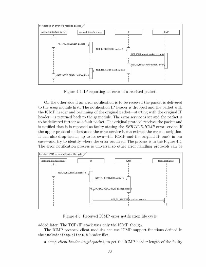
Figure 4.4: IP reporting an error of a received packet.
On the other side if an error notification is to be received the packet is deliveredto the icmp module first. The notification IP header is dropped and the packet withthe ICMP header and beginning of the original packet—starting with the original IPheader—is returned back to the ip module. The error service is set and the packet isto be delivered further as a fault packet. The original protocol receives the packet andis notified that it is reported as faulty stating the SERVICE ICMP error service. Ifthe upper protocol understands the error service it can extract the error description.It can also drop header up to its own—the ICMP and the original IP one’s in ourcase—and try to identify where the error occurred. The process is in the Figure 4.5.The error notification process is universal so other error handling protocols can be
Figure 4.5: Received ICMP error notification life cycle.
added later. The TCP/IP stack uses only the ICMP though.The ICMP protocol client modules can use ICMP support functions defined in
the include/icmp client.h header file:
• icmp client header length(packet) to get the ICMP header length of the faulty
53
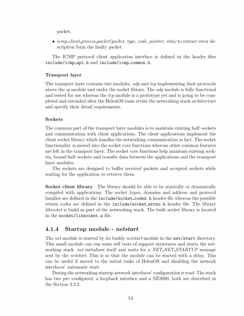
packet.
• icmp client process packet(packet, type, code, pointer, mtu) to extract error de-scription form the faulty packet.
The ICMP protocol client application interface is defined in the header filesinclude/icmp api.h and include/icmp common.h.
Transport layer
The transport layer contains two modules, udp and tcp implementing their protocolsabove the ip module and under the socket library. The udp module is fully functionaland tested for use whereas the tcp module is a prototype yet and is going to be com-pleted and extended after the HelenOS team revise the networking stack architectureand specify their detail requirements.
Sockets
The common part of the transport layer modules is to maintain existing half–socketsand communication with client applications. The client applications implement theclient socket library which handles the networking communication in fact. The socketfunctionality is moved into the socket core functions whereas other common featuresare left in the transport layer. The socket core functions help maintain existing sock-ets, bound half–sockets and transfer data between the applications and the transportlayer modules.
The sockets are designed to buffer received packets and accepted sockets whilewaiting for the application to retrieve them.
Socket client library The library should be able to be statically or dynamicallycompiled with applications. The socket types, domains and address and protocolfamilies are defined in the include/socket codes.h header file whereas the possiblereturn codes are defined in the include/socket errno.h header file. The librarylibsocket is build as part of the networking stack. The built socket library is locatedin the socket/libsocket.a file.
4.1.4 Startup module - netstart
The net module is started by its buddy netstart module in the net/start directory.This small module can run some self tests of support structures and starts the net-working stack. net initializes itself and waits for a NET NET STARTUP messagesent by the netstart. This is so that the module can be started with a delay. Thiscan be useful if moved to the initial tasks of HelenOS and disabling the networkinterfaces’ automatic start.
During the networking startup network interfaces’ configuration is read. The stackhas two pre–configured, a loopback interface and a NE2000, both are described inthe Section 3.2.2.
54
The configured modules are initialized for both. The driver task is started andthe probe message from the networking module activates device probing. On successthe device should be operational and ready but not yet enabled—it can but does notsend nor receive data. This allows further stack setup as it delays receiving packetsfrom the device. The network interface layer module is started and requested toregister the network interface second. It registers itself as the packet supplier andconsumer of the device. The inter–network layer module is started and requested toregister the network interface at the nil last. The network interface is then started.The process is depicted in detail in the UML diagrams Section B.3.
4.1.5 Extending the networking stack
In this section a principle of integration of new modules into the networking stack isdescribed. One of the goal was to develop an extendable networking stack and hereis a brief manual.
Each new module has to be added as one of the RD SRVS tasks in the make fileboot/arch/ia32/Makefile.inc in the HelenOS source directory to be included inthe boot image. Furthermore, the module service has to be defined in the header fileuspace/lib/libc/include/ipc/services.h in the HelenOS source directory.
Most of the modules need to be registered by the add module() function some-where in the stack as well. This is due to the fact that the networking stack has toknow the module in order to use it. Since then the module can be configured andused.
Network interface driver
A new network interface driver should implement the interface defined in the headerfile netif/netif module.h.
The driver should be built with the netif/netif.c source file. The standalonedriver is built with the netif/netif standalone.c and nil/nil remote.c sourcefiles while the bundle driver is built with the netif/netif nil bundle.c source fileand the appropriate nil/(module name)/(module name).c source file. Please, seethe netif/lo/Makefile as a reference of other needed source files.
In the net initialization function net initialize() a module description has to beadded by a function call similar to
add_module( NULL, & net_globals.modules, NAME, FILENAME, SERVICE, \
0, connect_to_service ));
Network interface layer
A new network interface layer module should implement the interfaces defined inthe header files include/nil interface.h and nil/nil module.h and process themessages defined in the nil/nil messages.h header file.
55
The module should be built with a standalone module stub based on the sourcefile nil/nildummy/nildummy module.c changing the NAME definition and the SER-VICE constants accordingly. Please, see the nil/nildummy/Makefile as a referenceof other needed source files.
If the module is intended to function underneath the arp module, the proto-col mapping needs to be defined in the hardware map() function in the header fileinclude/protocol map.h. In the net initialization function net initialize() a moduledescription has to be added by a function call similar to
add_module( NULL, & net_globals.modules, NAME, FILENAME, SERVICE, \
0, connect_to_service ));
Inter–network layer
A new inter–network layer module should implement the interface defined in theheader file include/il interface.h and process the messages defined in the headerfile il/il messages.h.
The module should be built with a standalone module stub based on the sourcefile il/ip/ip module.c changing the NAME definition and the SERVICE constantsaccordingly. Please, see the il/ip/Makefile as a reference of other needed sourcefiles.
If the module is intended to function upon the eth module, the protocol map-ping needs to be defined in the protocol [un]map() and lsap [un]map() functions inthe include/protocol map.h header file. The further networking stack integrationdepends on the module type.
General inter–network module In the net architecture specific initializationfunction net initialize build() a module description has to be added by commandssimilar to
task_id = spawn( FILENAME );
if( ! task_id ) return EINVAL;
ERROR_PROPAGATE( add_module( NULL, & net_globals.modules, NAME, \
FILENAME, SERVICE, task_id, NAME_connect_module ));
for the modular networking, and
ERROR_PROPAGATE( REGISTER_ME( SERVICE, & phonehash ));
ERROR_PROPAGATE( add_module( NULL, & net_globals.modules, NAME, \
FILENAME, SERVICE, task_get_id(), NAME_connect_module ));
ERROR_PROPAGATE( NAME_initialize( client_connection ));
for the monolithic build. Furthermore, the messages have to be forwarded in themonolithic build altering the module message() function message switch like:
switch( IPC_GET_TARGET( call )){
case SERVICE:
56
return NAME_message( callid, call, answer, answer_count );
...
}else if( IS_NAME_MESSAGE( call )){
return NAME_message( callid, call, answer, answer_count );
and the start device() function like:
switch( netif->il->service ){
case SERVICE:
ERROR_PROPAGATE( NAME_device_req( netif->il->phone, \
netif->id, internet_service ));
ARP module A new ARP module should implement the interface defined inthe header file include/arp interface.h and process the messages defined in theil/arp/arp messages.h header file. Multiple ARP modules are supported only forthe modular networking architecture as the default arp is built and used in the bundlenet module.
In the ip initialization function ip initialize() a module description has to beadded by a command similar to
ERROR_PROPAGATE( add_module( NULL, & ip_globals.modules, ARP_NAME, \
ARP_FILENAME, SERVICE_ARP, arp_task_get_id(), \
arp_connect_module ));
Transport layer
A new transport layer module should implement the interface defined in the headerfile include/tl interface.h and process the messages defined in the header filetl/tl messages.h.
The module should be built with a standalone module stub based on the sourcefile tl/udp/udp module.c changing the NAME definition and the SERVICE con-stants accordingly. Please, see the tl/udp/Makefile as a reference of other neededsource files.
The module does not have to be added to the networking initialization, it canstand aside and can be started manually. If the module is to be integrated into thenetworking stack the following steps have to be taken. In the net architecture specificinitialization function net initialize build() a module description has to be added bycommands similar to
if( ! spawn( FILENAME )) return EINVAL;
for the modular networking, and
ERROR_PROPAGATE( REGISTER_ME( SERVICE, & phonehash ));
ERROR_PROPAGATE( NAME_initialize( client_connection ));
for the monolithic build. Furthermore, the messages have to be forwarded in themonolithic build altering the module message() function message switch like:
57
switch( IPC_GET_TARGET( call )){
case SERVICE:
return NAME_message( callid, call, answer, answer_count );
...
}else if( IS_NAME_MESSAGE( call )){
return NAME_message( callid, call, answer, answer_count );
If the new protocol is intended to be published in the socket library a socketprotocols mapping needs to be extended. A new static function to connect to theprotocol module has to be implemented:
/** Returns the NAME module phone.
* Connects to the NAME module if necessary.
* @returns The NAME module phone.
*/
static int socket_get_NAME_phone( void );
and the mapping extended in the socket() function like:
switch( domain ){
case PROTOCOL_FAMILY:
switch( type ){
case SOCK_TYPE:
if( ! protocol ) protocol = IPPROTO_DEFAULT;
switch( protocol ){
case IPPROTO_NAME:
phone = socket_get_NAME_phone();
service = SERVICE;
break;
4.1.6 Qemu network
In the common mode Qemu creates a simple network with a gateway and settles theguest system in. The network is 10.0.2.*, the gateway’s address 10.0.2.2 and the guestsystem has 10.0.2.15. Therefore a static configuration is possible and no additionalDHCP nor BOOTP implementations are necessary. On the other hand the guestsystem is behind a firewall. Qemu may be configured to forward some ports to theguest system and allows all outgoing traffic except ICMP and ARP protocols, so youcan ping only the gateway.
4.1.7 N.E.T. user protocols
The protocol script is written in an XML file respecting the DTD file protocol.dtd.Each script should refer to the DTD file and comply with it. The whole processstarting by a used protocol, connecting sequence, confirmation data, statuses anddisconnecting sequence may be defined. The script has to be in the current directorywhile running the application. Script semantics is as follows
58
Identification Basic protocol settings such as displayed name and lower communi-cation protocol (lower as BuiltinTCP or BuiltinUDP).
Connect A connecting sequence containing send and receive blocks and a targetstate. The application follows the sequence by sending and parsing the receiveddata. If the sequence is successful the target state is achieved. Next connectsequence is tried instead if present.
Confirm A set of patterns used by the other host to confirm sent data. If any ofthe confirm patterns matches the sent data are confirmed.
State A set of uniquely numbered states (number) of the protocol. Each state mayhave a command sequence (command). There is an optional target state fora command the protocol achieves on success. The command may contain vari-able data marked as %s which the user can replace by any character string.The normal percent sign has to be written as %%.
All A set of commands like in the state block which may be used in any state.
Disconnect A disconnecting sequence similar to the connecting one. The connectionis closed on success.
This can be of use for extending the networking stack with further protocols andapplications in the future.
4.2 Running and testing
The networking stack is integrated into HelenOS to proof its operability. After start-ing either the provided boot images from the attached CD or built from source filesin Qemu, the command line appears. The networking stack is started and initializedby running a command
# netstart
The networking stack is then started and configured network interfaces are enabled.The current configuration is printed out. Since that networking applications can berun using the command line as well.
4.2.1 Applications
A few networking applications are located in the app/ directory. Common functionsfor parsing command line arguments and printing textual networking error messagesare located in that directory as well.
The networking applications should be built with the libsocket library locatedin the socket/libsocket.a file. They can use functions and definitions from theinclude/socket.h header file which contains socket API and further includes:
• include/byteorder.h containing byte order manipulation,
59
• include/in.h containing IPv4 socket address structure,
• include/in6.h containing IPv6 socket address structure,
• include/inet.h containing socket address structure and parsing functions,
• include/socket codes.h containing address and protocol families and sockettypes and option levels, and
• include/socket errno.h containing socket and general error codes.
New applications can be added, for example into the app/ directory. A new subdirectory should be created with the source code and a simple Makefile
NAME = NAME_OF_THE_APPLICATION
NET_BASE = ../../
STRUCTURES = $(NET_BASE)structures/
include ../../../../../Makefile.config
## Sources
#
OUTPUT = $(NAME)
SOURCES = \
$(NAME).c \
...
LIBS += ../../socket/libsocket.a
include $(NET_BASE)Makefile.module
The source code should include the ../../include/socket.h header file. The nextstep is to tell networking stack to compile the module and HelenOS to include it intothe boot image. An entry has to be added to the net Makefile
DIRS = \
app/DIRECTORY/NAME_OF_THE_APPLICATION \
...
in the boot/arch/ia32/Makefile.inc file in the HelenOS source directory, it hasto be added as one of the RD SRVS tasks
RD_SRVS = \
$(USPACEDIR)/srv/net/app/DIRECTORY/NAME_OF_THE_APPLICATION \
...
The application can be run by the command then
# NAME_OF_THE_APPLICATION
60
4.2.2 Software prerequisites
The networking and TCP/IP stack is implemented for the ia32 7 architecture on topof HelenOS 0.4.1 (Escalopino) 8, the most current stable release of HelenOS. So farthe only one operational network interface supported is in Qemu 0.10.2 and newer 9.To run Qemu a script contrib/conf/qemu.sh for Linux or contrib/conf/qemu.batfor Windows in the HelenOS source directory can be used. The qemu and its librarieshave to be installed and in the path. These scripts set all the necessary parameterswith some ports redirected from the local host to the guest system. For testingpurposes at least a low level communication application is recommended, N.E.T.,netcat etc.
In order to build HelenOS and the networking stack from sources a few tools arerequired:
• binutils in version 2.19.1 10,
• gcc–core in version 4.3.3 11,
• gcc–objc in version 4.3.3, and
• gcc–g++ in version 4.3.3.
All these can be downloaded and installed as cross–compilers on Linux using a scriptcontrib/toolchain.sh in the HelenOS source directory.
In addition rats 12, a static source code analyzer, and Doxygen 13, a documentationgenerator, were used. All development was tracked in the HelenOS subversion 14
repository.
7IA32 is the most common (supported) architecture.8HelenOS website: <http://www.helenos.org/>9Qemu website: <http://www.qemu.org/>
10binutils website: <http://www.gnu.org/software/binutils/>11GCC website: <http://gcc.gnu.org/>12RATS website: <http://www.fortify.com/security-resources/rats.jsp>13Doxygen website: <http://www.stack.nl/∼dimitri/doxygen/index.html>14Subversion website: <http://subversion.tigris.org/>
61
Chapter 5
Evaluation
In this section we compare the performance of the modular and the monolithicarchitectures which was one of the goals of this work.
In order to test all levels of the stack the topmost approach was chosen. It meansa testing application using sockets to communicate with another one. The commu-nication drifted down to a network interface and back up to the other application.The other application was the echo server just repeating back the received data. Thissimulates a real load on the networking stack and the localhost connection ensurestesting of the whole communication process.
The default compile–time configuration for the ia32 architecture was kept exceptthat the Debug build was switched off. The networking stack was compiled as bothmodular and monolithic (Modular and Monolithic boot images).
Four versions of HelenOS were compiled for the testing purposes in fact. In ad-dition to the configuration mentioned above, another two variants were compiledwith one IP interface call cached (Modular-1 and Monolithic-1). The call was theip packet size req() function called by the sendto() function in the UDP module. Thisfunction call queries the IP module about the packet dimensions for the target des-tination. The UDP protocol is stateless and furthermore packets sent by one socketcan have different destinations and can be routed via different network interfaces.Therefore the right packet dimensions should be agreed for each outgoing packet.This is the reason why this caching is sustainable only for demonstration purposesof the following tests.
HelenOS was always run anew in Qemu to avoid an interference with anothersystem and to provide uniform conditions for each test. Therefore, the absoluteresults have to be taken with reserve as there is a significant slowdown when usingan emulator.
The raw outcomes of the measurements are in the appendices Section A whereasaverage and aggregated values are discussed in this section.
62
5.1 Nettest2 – data transfer performance
The fist test measures the data transfer performance. The goal is to identify mainfactors influencing the data transfer performance.
A testing application nettest2 was created performing the following functions
CR sockets create() to create sockets
SR sockets sendto recvfrom() to send and receive datagrams of all sockets, eachdatagram is sent and a reply is received consequently so the next datagram issent after the reply arrival
ST sockets sendto() to send datagrams of all sockets, all datagrams are sent withoutreceiving any replies
RF sockets recvfrom() to receive reply datagrams of all sockets for all sent datagrams
SC sockets close() to close sockets
There are command line arguments to specify the number of sockets (n), the numberof datagrams (m) per socket and the datagram length (s). The application involvesin total:
• one message to connect to the transport layer module,
• n IPC messages to create sockets,
• n IPC messages to close sockets, and
• 2 ∗ n ∗ m datagram transfers as depicted in the appendix Section B.4, eachincluding
– 26 IPC messages for Modular, 24 for Modular-1 and 12 for both Mono-lithic,
– 4 times s–byte transfers of data,
– 8 times 16 byte transfers of destination addresses for both Modular, 4 timesfor both Monolithic,
– 2 times 12 byte transfers of IP pseudo headers for both Modular.
The total times taken of data transfers SR and ST+RF were measured.The first test variant was set to use 1 socket and 100 datagrams each of 1024 bytes.
The total amount of 100 kB of data was transferred both ways. The application wasrun twice by the command
# nettest2 -p 7 -t SOCK_DGRAM -n 1 -m 100 -s 1024 127.0.0.1
63
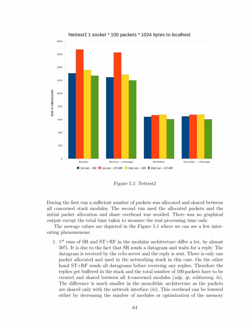
Figure 5.1: Nettest2
During the first run a sufficient number of packets was allocated and shared betweenall concerned stack modules. The second run used the allocated packets and theinitial packet allocation and share overhead was avoided. There was no graphicaloutput except the total time taken to measure the real processing time only.
The average values are depicted in the Figure 5.1 where we can see a few inter-esting phenomenons:
1. 1st runs of SR and ST+RF in the modular architecture differ a lot, by almost30%. It is due to the fact that SR sends a datagram and waits for a reply. Thedatagram is received by the echo server and the reply is sent. There is only onepacket allocated and used in the networking stack in this case. On the otherhand ST+RF sends all datagrams before receiving any replies. Therefore thereplies get buffered in the stack and the total number of 100 packets have to becreated and shared between all 4 concerned modules (udp, ip, nildummy, lo).The difference is much smaller in the monolithic architecture as the packetsare shared only with the network interface (lo). This overhead can be loweredeither by decreasing the number of modules or optimization of the memory
64
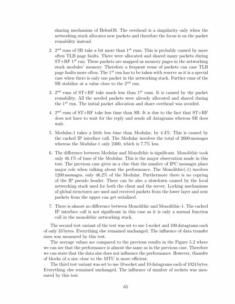
sharing mechanism of HelenOS. The overhead is a singularity only when thenetworking stack allocates new packets and therefore the focus is on the packetreusability instead.
2. 2nd runs of SR take a bit more than 1st runs. This is probably caused by moreoften TLB page faults. There were allocated and shared many packets duringST+RF 1st run. These packets are mapped as memory pages in the networkingstack modules’ memory. Therefore a frequent reuse of packets can case TLBpage faults more often. The 1st run has to be taken with reserve as it is a specialcase when there is only one packet in the networking stack. Further runs of theSR stabilize at a value close to the 2nd run.
3. 2nd runs of ST+RF take much less than 1st runs. It is caused by the packetreusability. All the needed packets were already allocated and shared duringthe 1st run. The initial packet allocation and share overhead was avoided.
4. 2nd runs of ST+RF take less time than SR. It is due to the fact that ST+RFdoes not have to wait for the reply and sends all datagrams whereas SR doeswait.
5. Modular-1 takes a little less time than Modular, by 4.4%. This is caused bythe cached IP interface call. The Modular involves the total of 2600messageswhereas the Modular-1 only 2400, which is 7.7% less.
6. The difference between Modular and Monolithic is significant. Monolithic tookonly 46.1% of time of the Modular. This is the major observation made in thistest. The previous case gives us a clue that the number of IPC messages playsmajor role when talking about the performance. The Monolithic(-1) involves1200messages, only 46.2% of the Modular. Furthermore there is no copyingof the IP pseudo header. There can be also a slowdown caused by the localnetworking stack used for both the client and the server. Locking mechanismsof global structures are used and received packets from the lower layer and sentpackets from the upper can get serialized.
7. There is almost no difference between Monolithic and Monolithic-1. The cachedIP interface call is not significant in this case as it is only a normal functioncall in the monolithic networking stack.
The second test variant of the test was set to use 1 socket and 100 datagrams eachof only 33 bytes. Everything else remained unchanged. The influence of data transfersizes was measured by this test.
The average values are compared to the previous results in the Figure 5.2 wherewe can see that the performance is almost the same as in the previous case. Thereforewe can state that the data size does not influence the performance. However, thansferof blocks of a size close to the MTU is more efficient.
The third test variant was set to use 10 socket and 10 datagrams each of 1024 bytes.Everything else remained unchanged. The influence of number of sockets was mea-sured by this test.
65
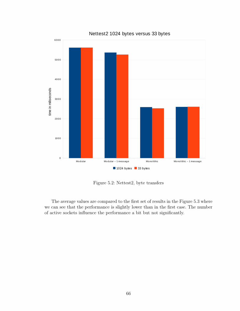
Figure 5.2: Nettest2, byte transfers
The average values are compared to the first set of results in the Figure 5.3 wherewe can see that the performance is slightly lower than in the first case. The numberof active sockets influence the performance a bit but not significantly.
66
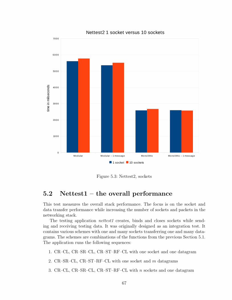
Figure 5.3: Nettest2, sockets
5.2 Nettest1 – the overall performance
This test measures the overall stack performance. The focus is on the socket anddata transfer performance while increasing the number of sockets and packets in thenetworking stack.
The testing application nettest1 creates, binds and closes sockets while send-ing and receiving testing data. It was originally designed as an integration test. Itcontains various schemes with one and many sockets transferring one and many data-grams. The schemes are combinations of the functions from the previous Section 5.1.The application runs the following sequences:
1. CR–CL, CR–SR–CL, CR–ST–RF–CL with one socket and one datagram
2. CR–SR–CL, CR–ST–RF–CL with one socket and m datagrams
3. CR–CL, CR–SR–CL, CR–ST–RF–CL with n sockets and one datagram
67
4. CR–SR–CL, CR–ST–RF–CL with n sockets and m datagrams
This progress increases the load of the networking stack and ensures its operability.There are command line arguments to specify the maximum number of sockets (n)and datagrams (m) and the datagram length (s). The application involves in total:
• one message to connect to the transport layer module,
• 5 ∗ (n + 1) IPC messages to create sockets,
• 5 ∗ (n + 1) IPC messages to close sockets, and
• 2∗(n+m+1)+n∗m datagram transfers as depicted in the appendix Section B.4,each including
– 26 IPC messages for Modular, 24 for Modular-1 and 12 for both Mono-lithic,
– 4 times s–byte transfers of data,
– 8 times 16 byte transfers of destination addresses for both Modular, 4 timesfor both Monolithic,
– 2 times 12 byte transfers of IP pseudo headers for both Modular.
The total time taken was measured.The first test variant was set to use 10 sockets and 10 datagrams each of 1024 bytes.
Therefore there will be a peak of 10 sockets and 100 buffered packets in the stack.The total amount of 142 kB of data is transferred both ways. The application wasrun twice by the command
# nettest1 -p 7 -t SOCK_DGRAM -n 10 -m 10 -s 1024 127.0.0.1
During the first run a sufficient number of packets is allocated and shared between allconcerned stack modules. The second run uses the allocated packets and the initialpacket allocation and share overhead is avoided. There was no graphical outputexcept the total time taken to measure the real processing time only.
The average values are depicted in the Figure 5.4 where we can see that thedifference between Modular and Monolithic is significant. The Monolithic took only50% of the Modular. There can be many reasons as already mentioned. If we havea look at the Modular-1 it did a bit better. The Modular involved 3803 IPC messageswhereas the Modular-1 involved only 3519messages, which is 92.5%. The total timefell by 5.3% in this case. This complies with the nettest2 results as the data trans-fer performance is major part of this test as well. Other parts of the test such assocket creating and closing involve only one IPC message each in both modular andmonolithic variants. Therefore the result is the same as it was in the Section 5.1.
68
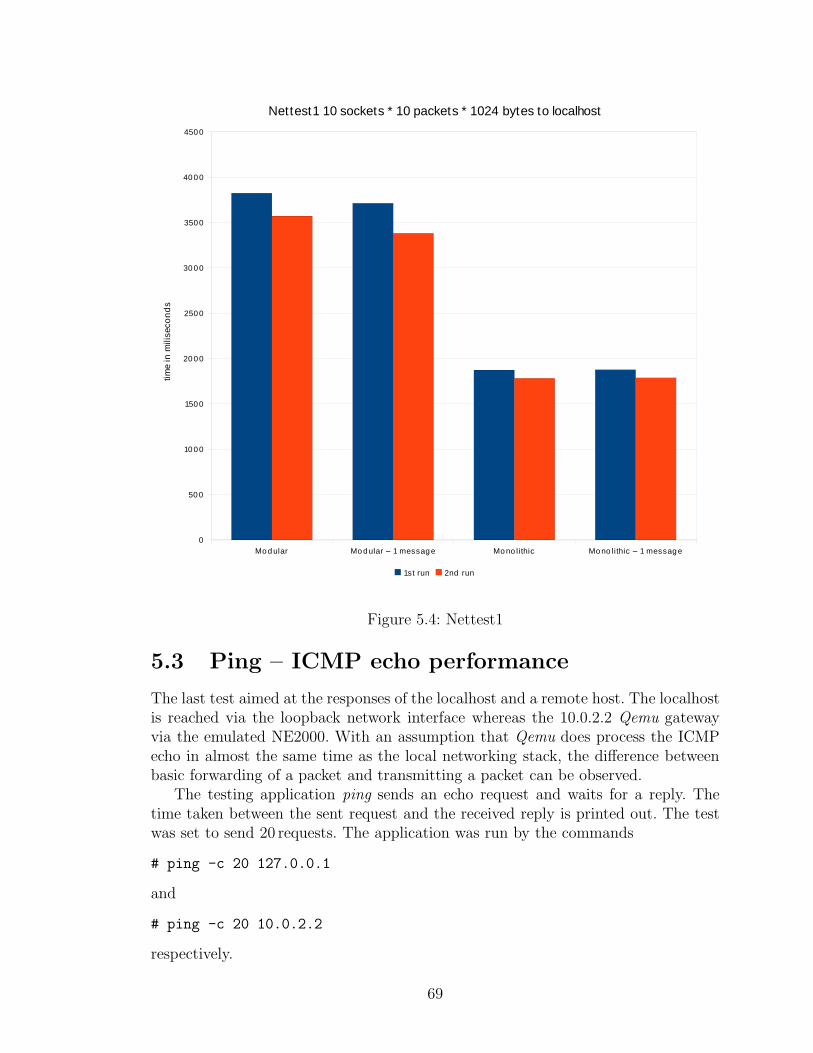
Figure 5.4: Nettest1
5.3 Ping – ICMP echo performance
The last test aimed at the responses of the localhost and a remote host. The localhostis reached via the loopback network interface whereas the 10.0.2.2 Qemu gatewayvia the emulated NE2000. With an assumption that Qemu does process the ICMPecho in almost the same time as the local networking stack, the difference betweenbasic forwarding of a packet and transmitting a packet can be observed.
The testing application ping sends an echo request and waits for a reply. Thetime taken between the sent request and the received reply is printed out. The testwas set to send 20 requests. The application was run by the commands
# ping -c 20 127.0.0.1
and
# ping -c 20 10.0.2.2
respectively.
69
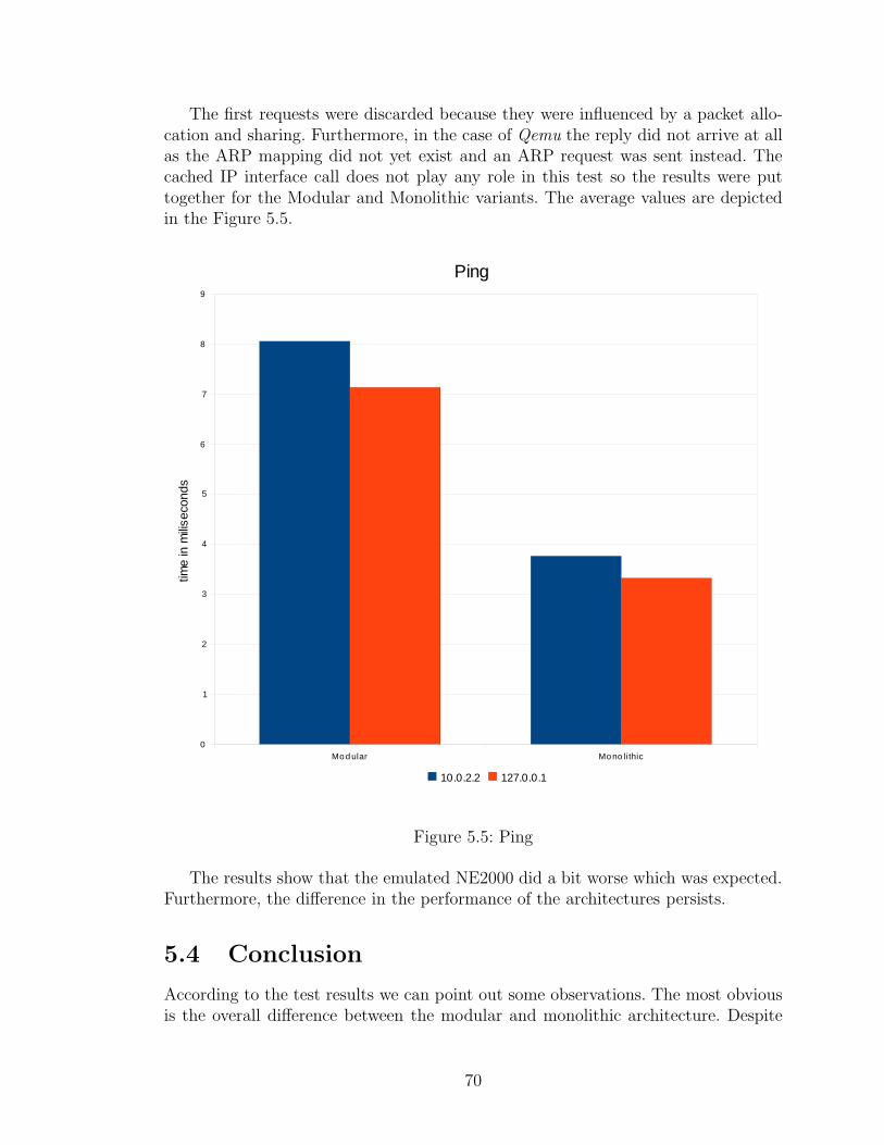
The first requests were discarded because they were influenced by a packet allo-cation and sharing. Furthermore, in the case of Qemu the reply did not arrive at allas the ARP mapping did not yet exist and an ARP request was sent instead. Thecached IP interface call does not play any role in this test so the results were puttogether for the Modular and Monolithic variants. The average values are depictedin the Figure 5.5.
Figure 5.5: Ping
The results show that the emulated NE2000 did a bit worse which was expected.Furthermore, the difference in the performance of the architectures persists.
5.4 Conclusion
According to the test results we can point out some observations. The most obviousis the overall difference between the modular and monolithic architecture. Despite
70
the results the modular architecture could be further optimized and its advantagescould overbalance the performance loss.
There is a significant overhead when new packets are created and shared betweennetworking stack modules. This overhead could be lowered only by optimizing theHelenOS memory sharing.
On the other hand the slowdown caused by IPC messages in general is moreimportant. It influences the overall and long–run performance of the networkingstack. In order to keep the modular design the total number of modules cannot belowered. Optimization and caching of IPC messages should be performed instead.There could be introduced faster IPC calls for frequently used messages using lessarguments or some sorts of piggybacking. Arguments while passing packets couldbe also transferred in the packets themselves as are the addresses now. The lockingconcept in the networking stack modules can be also revised if there could be moreshared accesses and less exclusive ones.
Interesting is the fact that the packet size does not influence the performance.Although the same data would get transferred in more packets the data copying intopackets itself does not slow down the datagram transfers.
71
Chapter 6
Other architectures
In this section we describe other operating systems’ networking stacks. We writeabout the general concept of the stacks, the authors’ motivation and goals and someof the main benefits and features. The list is focused on the main interesting distri-butions.
6.1 BSD
Berkeley Software Distribution was the first operating system implementing theTCP/IP Suite. Their first implementation appeared in 1983 in the 4.2BSD aftera close cooperation with ARPA. The focus was on the protocol suite itself. The4.4BSD networking stack is often considered as the reference implementation [11].It allowed the TCP/IP Suite to spread wide. The BSD networking stack introducedsocket API which became a de facto standard as well.
The BSD stack attempts to be the fastest networking stack. It was the first stackbreaking 1Mpps, routing of one million packets per second [14].
The networking stack is implemented in the kernel as one subsystem. Thereforeinterface calls are just normal function calls which increases performance as in thecase of our monolithic configuration.
The stack uses mbuf structure to hold packets. The mbuf is a fixed size block andlarger packets are chains of such blocks. The fixed size is a requirement of a SLABallocator. Although the buffers are not reused as our packets, the SLAB allocatordoes a very similar thing. It reserves the buffers in the memory and allocates themas needed. The allocation overhead is there for each new packet, however, it is muchlower than our memory sharing. On the other hand our packet reuse takes just oneIPC message and uses no dynamic allocation.
The security of the BSD networking stack tends to be also very high [3]. Theauthors of the stack discovered many vulnerabilities of protocols before they wereabused. They try to use pseudo–random number generators where possible which ledto resistance against some blind insertion attacks targeted on sequence numbering.The counters, session identifiers and timestamps are some of the examples.
Furthermore, the stack does not implement all features of RFCs as some were
72
considered vulnerable or needless. The stack ignores IP options, and some suspiciousICMP errors for example [15].
BSD uses its own network interface drivers and NDISwrapper, which is a quitecontroversial project. NDIS compatible drivers are included and used by the BSDstack. These drivers are mostly third party drivers developed for Microsoft WindowsNDIS API. Therefore the wrapper introduces third party and often closed code rightinto the kernel mode. This approach emerged from the fact that there are manynetwork interfaces and the manufacturers often support only the NDIS API.
There is one specialty with socket identifiers. Sockets identifiers in BSD referto files so the socket API and even the file API can be used to send and receivedata. The sockets are propagated to applications as regular files whereas the systemtreats them in a different way. This allows passing sockets to some reading or writingfunctions as file descriptors. On the other hand it needs deeper system integrationof the socket API. Our networking stack stands still apart from other subsystems ofHelenOS.
6.2 Linux
The Linux networking stack [2] is very similar to the BSD networking stack, thewhole stack is in the kernel, uses BSD socket API, sockets as special files, a packetbuffer called sk buff, its own drivers and NDISwrapper. However, it is not a clone ofthe BSD networking stack, it has just the same philosophy.
The stack is in fact a compound of many kernel modules. Nevertheless, thesemodules are compiled or loaded into the kernel and run in the kernel mode. Themodules register their interface functions as pointers and use global data structureswhich reside in the kernel memory. This is for performance reasons again.
The programming security reasons stay a bit aside even though the Linux is anopen source project and has thousands of developers. It is, therefore, hard to reviseall the source code running in the kernel mode.
Linux kernel contains a netfilter which filters the network traffic according toconfigured rules. It uses hooks in the networking stack to be informed about packetsat certain times of the processing. This hooks are implemented as function pointersas well to preserve the performance.
The Linux kernel itself is influenced by the networking stack. One example isreceived frames retrieval. There are four possibilities drivers can use. Nevertheless,the drivers are not forced to use the most efficient. An interrupt handler can be usedto transfer the frames into the driver’s receive queue while blocking any other processon the CPU as the interrupts are disabled. Another option is to use bottom half andtop half interrupt handlers where only the necessary part of the interrupt handlingis treated by the top half. The bottom half is deferred and runs as a normal processthen. The bottom halves were internally changed to the third option, softirqs. Thesoftirq runs as a normal thread with interrupts enabled, however, the kernel does notallow another softirq to run on the CPU before the previous finishes. This decreasedthe overhead as the kernel was altered a bit. The last option is polling where the
73
driver asks frequently the network interface to provide received frames. This is veryuseful when the load is too high that there are so many interrupts that the drivercan barely get to the CPU to retrieve some of the received frames and the newlyreceived ones are discarded.
In comparison to HelenOS, only the IRQ recognition command sequence is runin the kernel interrupt handler with interrupts disabled. The driver is notified by anIPC message and the callback function does the processing. Although it is similar tothe bottom half, the standard IPC mechanism is used.
6.3 Windows
Microsoft Windows are the most used operating systems. The networking stack wasintegrated in early 1990s and used the NetBIOS interface. A newer interface Winsockwas added in 1993, and its newer version 2.2 comes from 1996. The Winsock interfaceis quite similar to the BSD socket interface and it supports both synchronous andasynchronous socket function calls.
The first version of the stack used some parts of the BSD implementation. How-ever, the stack was completely rewritten for Windows 2000 [13]. The Windows 2000was an “Internet–ready” release of Windows. It provided support for multiple net-work interfaces, IP routing, default gateways, VPNs, firewall hooks and other tech-nologies. The stack was in the kernel and accessible by system calls as well. At thebottom of the stack there was a packet scheduler, a central module for queueing andscheduling packets on top of NDIS drivers. This gave another layer of abstractionand shifted some common functionality from drivers to the stack. A piquancy wasthe emulation of wireless network interfaces as normal wired once.
Nevertheless, there is already a newer version of the stack since Windows Vista [5].It is called the “Next Generation TCP/IP Stack”. The stack is still an integral partof the operating system and implements much more RFCs than the previous stack.The stack is internally more modular and dynamic. Its configuration can be changedeven when running.
This release removed the packet scheduler and the wired emulation of wirelessnetwork interfaces. The overall support for wireless network interfaces is much better.This release implements native IPv6 and changes the network layer into a dual IPlayer with both IPv4 and IPv6 available. There are also security improvements ineasier IPsec configuration and a new Windows Filtering Platform which allows otherapplications to use the filtering engine integrated into the networking stack.
6.4 Minix
Minix is probably the most famous microkernel because of its author Andrew Tanen-baum [27]. The system is under development since 1980s.
Although Minix is a microkernel operating system, the networking stack is inone large module using BSD sockets API. Currently, there is a plan to break its
74

networking module into separate server modules 1. Their results could be interestingin comparison to this work.
Minix does not support many network interfaces, however, the drivers are simpleand functional. One of them is ported in our stack. The drivers support vectoredI/O which allows packets to be chains of memory blocks. These block are not sharedbut copied from the networking stack to the drivers’ address spaces by system calls.There is not a single packet buffer structure.
Other microkernel operating systems tend to use the monolithic networking mod-ule as well (EROS, Mach, JariOS, QNX Neutrino RTOS . . . ).
1A project to split the Minix networking stack into number of drivers and servers (IP, UDP,TCP...) was put up in October 2009.
75
Chapter 7
Conclusion
A functional networking stack is a complex subsystem as it spans over many levels ofabstraction. Nevertheless, there is just a simple interface on top of it. A lot of workis to be done under the hood to make the stack operational.
In this work we analyzed a networking stack in general. Modular and mono-lithic architectures were introduced and compared. The modular architecture canbe viewed as a service oriented architecture whereas the monolithic as a standalonesubsystem. The advantages and disadvantages of both architectures were discussed.
The main focus of the work was set to a modular networking stack for a microker-nel operating system. Having the modern concept in mind the author of this thesisevaluated and put together the age–proved protocols to create a new implementation.
The stack was also designed to support both modular and monolithic build whichallowed us to compare the modular stack to its monolithic equivalent. Some strengthsand weaknesses of the modular architecture were pointed out. One of the most men-tioned advantages of the monolithic architecture is the performance which was alsobacked up by test results. The main performance factors were analyzed and someoptimizations were proposed which could reduce the inequality of performance.
The idea of a strictly modular networking stack appeared independently in theMinix community a short time ago which supports our first intention as there isinterest in this topic. It might be a valuable comparison to this work if finished.
The presented master thesis fulfils its goals laid out in the introduction. Thenetworking stack design was evaluated and revised.A functional implementation inHelenOS was successfully achieved which made the main contribution of the workpossible, the comparison of the modular and monolithic architectures. Although theresults are not too supportive, we tried to give reasons to overbalance the performanceof the monolithic architecture in favour of the modular design. Furthermore, theimplemented networking stack is going to become an integral part of HelenOS.
Future work
The implemented networking stack was just a starting point for a long–term run.The networking stack features and capabilities should be improved and extended in
76
successive projects. One field are the optimizations of IPC messages. The network-ing stack implementation for a productive system should reduce the overhead andincrease its effectiveness.
Some often used features of the stack should be the goals of the first development.The the TCP protocol is not finished yet and some enhancement and optimizationRFCs could be also added. An IP fragments reassembly could be based on a TCPpacket buffering and timeout fibrils whereas the dynamic IP configuration involvesnew service modules running aside. The DHCP protocol uses UDP sockets for ex-ample.
A support for network interfaces is very limited now. Therefore a development ofnew drivers is highly recommended as it will help the networking stack to spread. Thedesigned driver architecture is, hopefully, flexible enough to allow easy developmentand usage of additional drivers.
Another field for extensive work is the overall security. It might be useful anddesirable to implement packet filtering and some sort of restrictions for ports andmodule extensions.
And last but not least, porting of many networking applications might follow.
77
Chapter 8
Terms and abbreviations
Here is a list of main networking terms and abbreviations. The abbreviations aredivided into organization names, protocols and others.
Terms
Host A single communicating or a network connected computer.
Network interface A piece of hardware providing networking communication, in-formally a network card.
Networking stack An actual implementation of cooperative networking protocolsin order to enable inter–computer communication.
Octet One byte in the networking terminology.
Packet A block of formatted data carried in a network.
Socket A virtual network connection between two hosts.
Sockets An API in the context of a networking stack, usually a BSD sockets inter-face is meant.
Organizations
ARPA Advanced Research Projects Agency, the American institution ARPA iscalled DARPA (D as Defense) now.
IANA Internet Assigned Numbers Authority, the central authority overseeing IPaddresses, protocol numbers and parameters allocation as well as root zone forthe DNS.
IEEE Institute of Electrical and Electronics Engineers, a worldwide professionalorganization focusing on electrical, electronics and information technology.
IETF Internet Engineering Task Force, an open standards organization with focuson developing and promoting Internet standards.
78
Protocols
ARP Address Resolution Protocol, a protocol used for mapping logical networkaddresses to underlying network addresses.
BOOTP Bootstrap Protocol, a protocol for an automatic configuration of a host ina computer network. The host uses this protocol only at its networking startup.
DHCP Dynamic Host Configuration Protocol, a protocol for an automatic dynamicconfiguration of a host in a computer network.
ICMP Internet Control Message Protocol, an error notification and support pro-tocol used in the TCP/IP Suite, serves to notify the other party about errorsand transfer network information.
IP Internet Protocol, a key inter–networking protocol in the TCP/IP Suite, it sim-ulates a connectionless, unreliable and best–effort packet delivery network.
TCP Transmission Control Protocol, a connection oriented and reliable transportprotocol upon IP.
UDP User Datagram Protocol, a connectionless, unreliable and best–effort trans-port protocol upon IP.
Other abbreviations
ARPANET ARPA Network, the original name of the first computer network.
BSD Berkeley Software Distribution, a Unix operating system developed at theUniversity of Colorado. The first operating system implementing the TCP/IPSuite.
CRC Cyclic Redundancy Check, a hash function computing a checksum.
DNS Domain Name System, a mechanism of translation textual addresses to IPaddresses.
IPsec Internet protocol security, a universal protocol suite for securing IP protocolpackets. It provides authentication, encryption and cryptographic keys negoti-ation.
ISO/OSI International Organization for Standardization / Open System Intercon-nection, a key networking reference model with seven layers of decomposition—Application, Presentation, Session, Transport, Network, Data Link and Physi-cal—but without concrete protocol specification.
MAC address Media Access Control address, a physical address of a network in-terface. This address is used to identify the source and the destination networkinterfaces of frames in the data link networking stack layer.
79
MTU Maximum Transmission Unit, the maximum size of data which can be trans-ferred at once. The MTU can be limited by a present as well as by a remotenetwork interface.
NDIS Network Driver Interface Specification, an API of network interfaces devel-oped by Microsoft and 3Com Corporation.
NetBIOS Network Basic Input/Output System, an original networking API usedin early Microsoft Windows.
RFC Request for comments, an IETF memorandum on Internet systems and stan-dards
TCP/IP The TCP/IP Suite is a networking architecture with four layers—Appli-cation, Transport, Inter–network and Network Interface—and concrete proto-col specifications.
80
Bibliography
[1] Appendix A, The Tanenbaum-Torvalds Debate in Open Sources: Voices from theOpen Source Revolution [on–line]. O’Reilly Media, January 1999, First edition.[cited November 20 2009]. ISBN 10: 1-56592-582-3. Available on the World WideWeb<http://www.oreilly.com/catalog/opensources/book/appa.html>
[2] BENVENUTI, C Understanding Linux Network Internals. O’Reilly Media, De-cember 29 2005. ISBN 13: 978-0-596-00255-8.
[3] BIANCUZZI, F. Security Focus. [on–line community]. Document version of2005-12-10. [cited December 5 2009]. OpenBSD’s network stack. Available onthe World Wide Web<http://www.securityfocus.com/columnists/361/1>.
[4] BRADEN, R.T.; BORMAN, D.A.; PATRIDGE, C. RFC1071: Computing theInternet checksum [on–line]. September 1 1988. [cited November 20 2009] Avail-able on–line<ftp://ftp.isi.edu/in-notes/rfc1071.txt>.
[5] DAVIES, J TCP/IP Fundamentals for Microsoft Windows. [on–line]. MicrosoftCorporation, Document version of 2008-02-06. [cited December 7 2009]. Avail-able on the World Wide Web<http://www.microsoft.com/downloads/details.aspx
?displaylang=en&FamilyID=c76296fd-61c9-4079-a0bb-582bca4a846f>.
[6] DECKY, M. Component–based General–purpose Operating System. In WDS’07Proceedings of Contributed Papers, Part I. Matfyzpress, 2007, 58—63. [citedNovember 14 2009]. ISBN 13: 978-80-7378-023-4. Available on the World WideWeb:<http://www.mff.cuni.cz/veda/konference/wds/contents/pdf07/
WDS07 110 i2 Decky.pdf>.
[7] DP8390D/NS32490D NIC Network Interface Controller. National Semiconduc-tor Corporation, July 1995. [cited November 17 2009]. Available on the WorldWide Web:<http://www.national.com/ds.cgi/DP/DP8390D.pdf>.
81
[8] HelenOS 0.2.0 design documentation [on–line]. June 18 2006. [cited November 142009]. Available on the World Wide Web:<http://www.helenos.org/doc/design.pdf>.
[9] LIEDTKE, J. On Microkernel Construction. In Proceedings of the 15th ACMSymposium on Operating System Principles (SOSP-15). Copper Mountain Re-sort, Colorado, December 1995. [cited November 25 2009]. Available on theWorld Wide Web<http://i30www.ira.uka.de/research/documents/l4ka/1995/
ukernel-construction.pdf>
[10] MALLORY, T.; KULLBERG, A. RFC1141: Incremental updating of the In-ternet checksum [on–line]. January 1 1990. [cited November 20 2009] Availableon–line<ftp://ftp.isi.edu/in-notes/rfc1141.txt>.
[11] MCKUSICK, M.K. et al. The Design and Implementation of the 4.4BSD Op-erating System. Addison Wesley Professional, May 10 1996, Second edition.ISBN 10: 0-201-54979-9.
[12] METCALFE, R.M.; BOGGS, D.R Ethernet: distributed packet switching forlocal computer networks. In Communications of the ACM. ACM, July 1976,vol. 19, no. 7, 395–404. ISSN: 0001-0782.
[13] Microsoft Corporation. Microsoft TechNet. [on–line knowledge database]. Mi-crosoft Windows 2000 TCP/IP Implementation Details. [cited December 72009]. Available on the World Wide Web<http://technet.microsoft.com/en-us/library/bb726981.aspx>.
[14] OPPERMANN, A. FreeBSD5 Network Enhancements. [on–line] SUCON 04,September 3 2004. [cited December 4 2009]. Available on the World Wide Web<http://people.freebsd.org/∼andre/FreeBSD-5.3-Networking.pdf>.
[15] OPPERMANN, A. New Networking Features in FreeBSD6. [on–line] EuroBS-DCon 05. [cited December 5 2009]. Available on the World Wide Web<http://people.freebsd.org/∼andre/
New%20Networking%20Features%20in%20FreeBSD%206.pdf>.
[16] PARZIALE, L. et al. TCP/IP Tutorial and Technical Overview [on–line]. Inter-national Business Machines Corporation Redbooks, December 19 2006, Eightedition. [cited December 27 2008]. ISBN 10: 0738494682. Available on the WorldWide Web<http://www.redbooks.ibm.com/redbooks/pdfs/gg243376.pdf>.
[17] POSTEL, J. RFC768: User Datagram Protocol [on–line]. August 28 1980. [citedNovember 20 2009] Available on–line<ftp://ftp.isi.edu/in-notes/rfc768.txt>.
82

[18] POSTEL, J. RFC791: Internet Protocol [on–line]. September 1 1981. [citedNovember 20 2009] Available on–line<ftp://ftp.isi.edu/in-notes/rfc791.txt>.
[19] POSTEL, J. RFC792: Internet Control Message Protocol [on–line]. September 11981. [cited November 20 2009] Available on–line<ftp://ftp.isi.edu/in-notes/rfc792.txt>.
[20] POSTEL, J. RFC793: Transmission Control Protocol [on–line]. September 11981. [cited November 20 2009] Available on–line<ftp://ftp.isi.edu/in-notes/rfc793.txt>.
[21] PLUMMER, D.C. RFC826: Ethernet Address Resolution Protocol: Or convert-ing network protocol addresses to 48.bit Ethernet address for transmission onEthernet hardware [on–line]. November 1 1982. [cited November 20 2009] Avail-able on–line<ftp://ftp.isi.edu/in-notes/rfc826.txt>.
[22] RIJSINGHANI, A. RFC1624: Computation of the Internet Checksum via Incre-mental Update [on–line]. May 1994. [cited November 20 2009] Available on–line<ftp://ftp.isi.edu/in-notes/rfc1624.txt>.
[23] RUBINI, A.; CORBET, J. Linux Device Drivers [on–line]. O’Reilly, June 2001,Second edition. [cited July 26 2008]. ISBN 10: 0-596-00008-1. Available on theWorld Wide Web:<http://www.xml.com/ldd/chapter/book/index.html>.
[24] SRIVASTAVA, V.; MOTANI, M. Cross–layer design: a survey and the roadahead. In Communications Magazine. IEEE, December 2005, vol. 12, no. 1,112–119.
[25] SUTTON, C. UCLA. [on–line magazine]. Document version of 2004-09-02. [citedDecember 5 2009]. Internet Began 35 Years Ago at UCLA with First MessageEver Sent Between Two Computers. Available on the World Wide Web<http://www.engineer.ucla.edu/stories/2004/Internet35.htm>.
[26] TANENBAUM, A.S. Computer Networks. Prentice Hall, 2002. [cited Novem-ber 14 2009]. ISBN 10: 0130661023. Available on the World Wide Web<http://books.google.cz/books?id=Pd-z64SJRBAC>.
[27] TANENBAUM, A.S.; WOODHULL, A.S. Operating Systems Designand Implementation, 3/E. Prentice Hall, April 1 2006, Third edition.ISBN 13: 9780131429383.
[28] WINSTON, I. RFC948: Two methods for the transmission of IP datagrams overIEEE 802.3 networks [on–line]. June 1 1985. [cited November 20 2009] Availableon–line<ftp://ftp.isi.edu/in-notes/rfc948.txt>.
83
[29] WONG, C.T. Minix Networking Documentation. [on–line]. Document version of2003-12-04. [cited December 6 2009]. Available on the World Wide Web<http://www.nyx.net/∼ctwong/minix/Minix startpage.htm>.
[30] ZAGHAL, R.Y.; KHAN, J.I. EFSM/SDL modeling of the original TCP standard(RFC793) and the Congestion Control Mechanism of TCP Reno [on–line]. KentState University, July 22 2005. [cited November 20 2009] Available on the WorldWide Web:<http://www.medianet.kent.edu/techreports/
TR2005-07-22-tcp-EFSM.pdf>.
[31] ZIMMERMANN, H. OSI Reference Model – The IS0 Model of Architecturefor Open Systems Interconnection. In Transactions on Communications. IEEE,April 1980, vol. 28, no. 4, 425–432. [cited November 14 2009]. Available on theWorld Wide Web<http://www.comsoc.org/livepubs/50 journals/pdf/
RightsManagement eid=136833.pdf>.
84
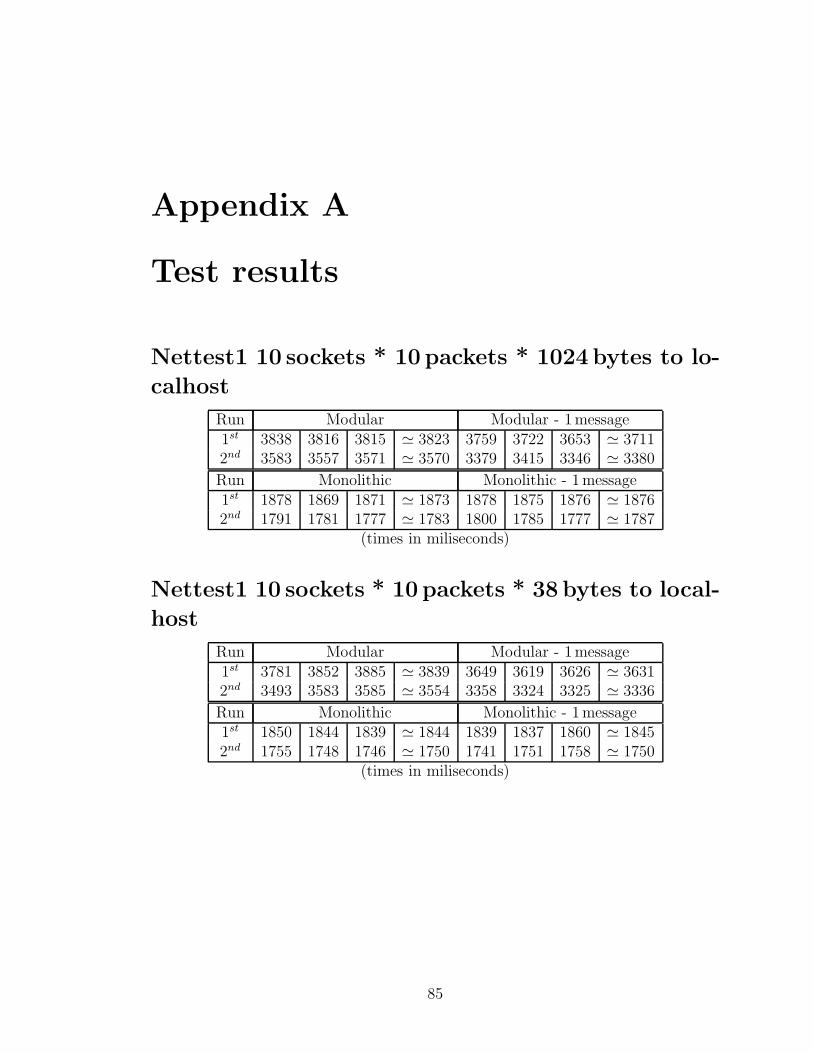
Appendix A
Test results
Nettest1 10 sockets * 10 packets * 1024 bytes to lo-
calhost
Run Modular Modular - 1message1st 3838 3816 3815 ≃ 3823 3759 3722 3653 ≃ 37112nd 3583 3557 3571 ≃ 3570 3379 3415 3346 ≃ 3380
Run Monolithic Monolithic - 1message1st 1878 1869 1871 ≃ 1873 1878 1875 1876 ≃ 18762nd 1791 1781 1777 ≃ 1783 1800 1785 1777 ≃ 1787
(times in miliseconds)
Nettest1 10 sockets * 10 packets * 38 bytes to local-
host
Run Modular Modular - 1message1st 3781 3852 3885 ≃ 3839 3649 3619 3626 ≃ 36312nd 3493 3583 3585 ≃ 3554 3358 3324 3325 ≃ 3336
Run Monolithic Monolithic - 1message1st 1850 1844 1839 ≃ 1844 1839 1837 1860 ≃ 18452nd 1755 1748 1746 ≃ 1750 1741 1751 1758 ≃ 1750
(times in miliseconds)
85
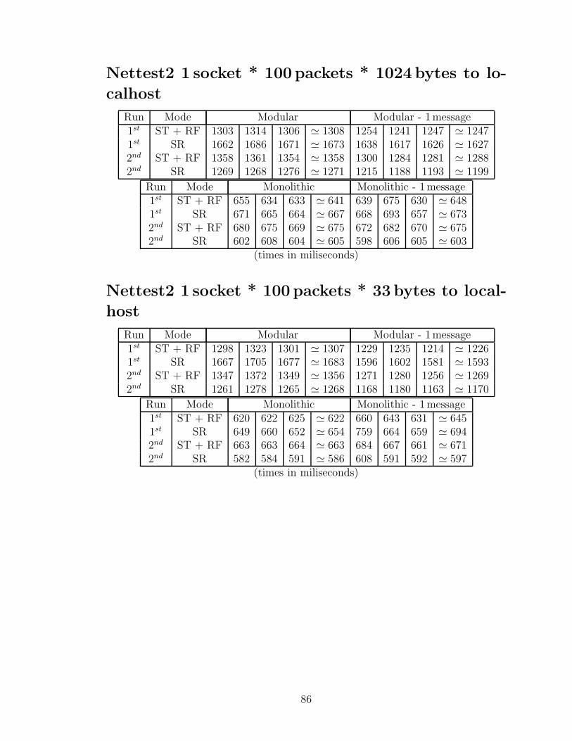
Nettest2 1 socket * 100 packets * 1024 bytes to lo-
calhost
Run Mode Modular Modular - 1message1st ST + RF 1303 1314 1306 ≃ 1308 1254 1241 1247 ≃ 12471st SR 1662 1686 1671 ≃ 1673 1638 1617 1626 ≃ 16272nd ST + RF 1358 1361 1354 ≃ 1358 1300 1284 1281 ≃ 12882nd SR 1269 1268 1276 ≃ 1271 1215 1188 1193 ≃ 1199
Run Mode Monolithic Monolithic - 1message1st ST + RF 655 634 633 ≃ 641 639 675 630 ≃ 6481st SR 671 665 664 ≃ 667 668 693 657 ≃ 6732nd ST + RF 680 675 669 ≃ 675 672 682 670 ≃ 6752nd SR 602 608 604 ≃ 605 598 606 605 ≃ 603
(times in miliseconds)
Nettest2 1 socket * 100 packets * 33 bytes to local-
host
Run Mode Modular Modular - 1message1st ST + RF 1298 1323 1301 ≃ 1307 1229 1235 1214 ≃ 12261st SR 1667 1705 1677 ≃ 1683 1596 1602 1581 ≃ 15932nd ST + RF 1347 1372 1349 ≃ 1356 1271 1280 1256 ≃ 12692nd SR 1261 1278 1265 ≃ 1268 1168 1180 1163 ≃ 1170
Run Mode Monolithic Monolithic - 1message1st ST + RF 620 622 625 ≃ 622 660 643 631 ≃ 6451st SR 649 660 652 ≃ 654 759 664 659 ≃ 6942nd ST + RF 663 663 664 ≃ 663 684 667 661 ≃ 6712nd SR 582 584 591 ≃ 586 608 591 592 ≃ 597
(times in miliseconds)
86
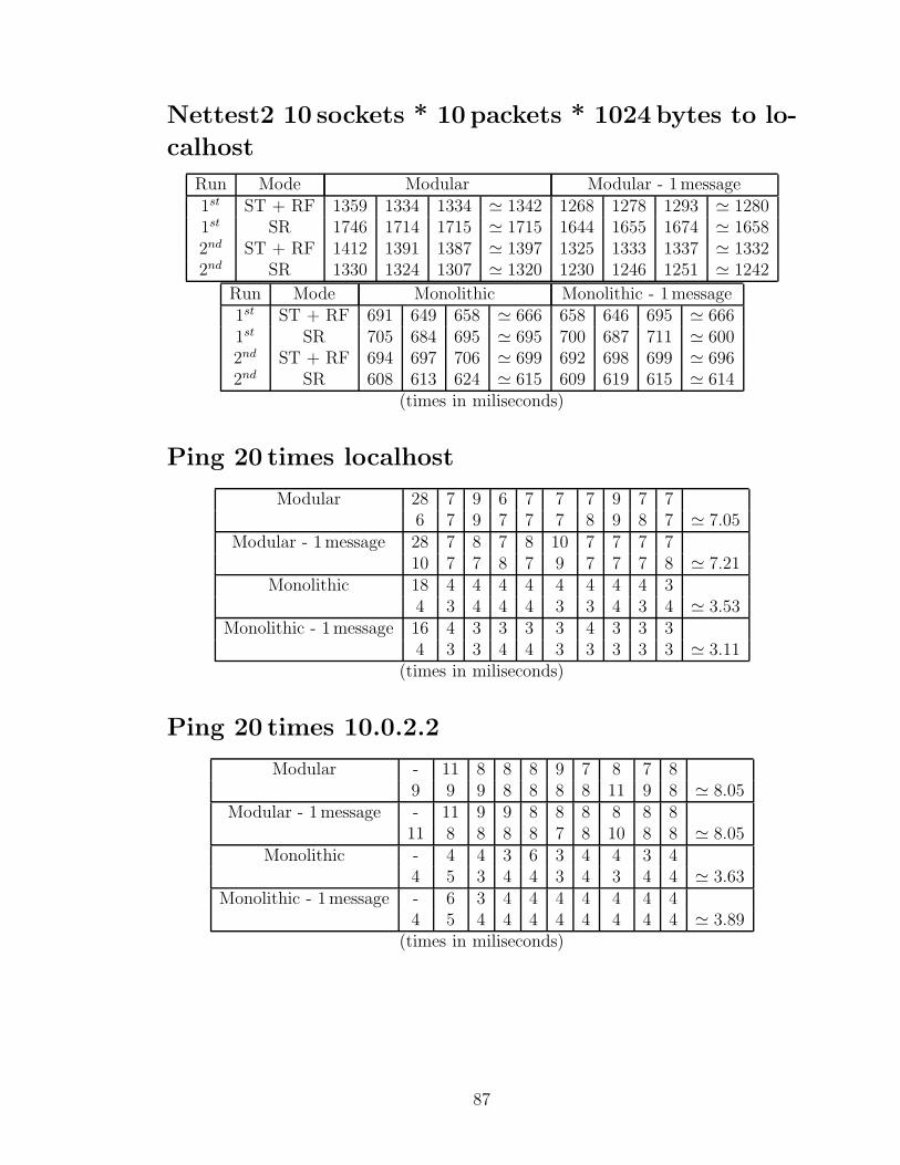
Nettest2 10 sockets * 10 packets * 1024 bytes to lo-
calhost
Run Mode Modular Modular - 1message1st ST + RF 1359 1334 1334 ≃ 1342 1268 1278 1293 ≃ 12801st SR 1746 1714 1715 ≃ 1715 1644 1655 1674 ≃ 16582nd ST + RF 1412 1391 1387 ≃ 1397 1325 1333 1337 ≃ 13322nd SR 1330 1324 1307 ≃ 1320 1230 1246 1251 ≃ 1242
Run Mode Monolithic Monolithic - 1message1st ST + RF 691 649 658 ≃ 666 658 646 695 ≃ 6661st SR 705 684 695 ≃ 695 700 687 711 ≃ 6002nd ST + RF 694 697 706 ≃ 699 692 698 699 ≃ 6962nd SR 608 613 624 ≃ 615 609 619 615 ≃ 614
(times in miliseconds)
Ping 20 times localhost
Modular 28 7 9 6 7 7 7 9 7 76 7 9 7 7 7 8 9 8 7 ≃ 7.05
Modular - 1message 28 7 8 7 8 10 7 7 7 710 7 7 8 7 9 7 7 7 8 ≃ 7.21
Monolithic 18 4 4 4 4 4 4 4 4 34 3 4 4 4 3 3 4 3 4 ≃ 3.53
Monolithic - 1message 16 4 3 3 3 3 4 3 3 34 3 3 4 4 3 3 3 3 3 ≃ 3.11
(times in miliseconds)
Ping 20 times 10.0.2.2
Modular - 11 8 8 8 9 7 8 7 89 9 9 8 8 8 8 11 9 8 ≃ 8.05
Modular - 1message - 11 9 9 8 8 8 8 8 811 8 8 8 8 7 8 10 8 8 ≃ 8.05
Monolithic - 4 4 3 6 3 4 4 3 44 5 3 4 4 3 4 3 4 4 ≃ 3.63
Monolithic - 1message - 6 3 4 4 4 4 4 4 44 5 4 4 4 4 4 4 4 4 ≃ 3.89
(times in miliseconds)
87
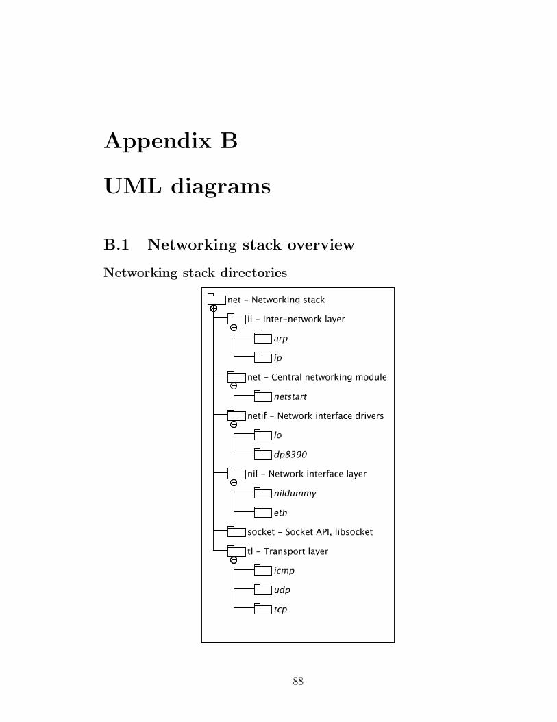
Appendix B
UML diagrams
B.1 Networking stack overview
Networking stack directories
88
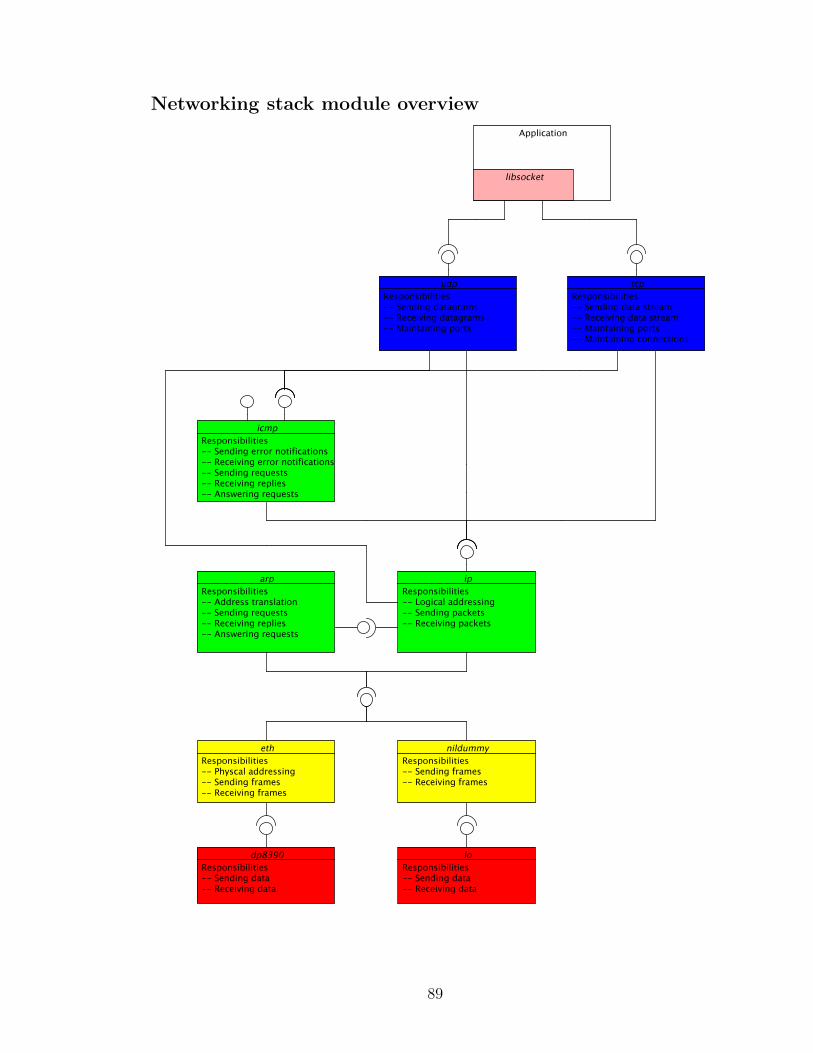
Networking stack module overview
89
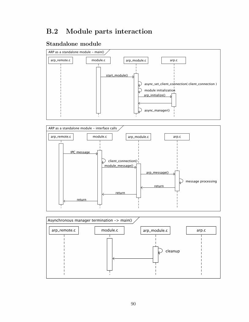
B.2 Module parts interaction
Standalone module
90
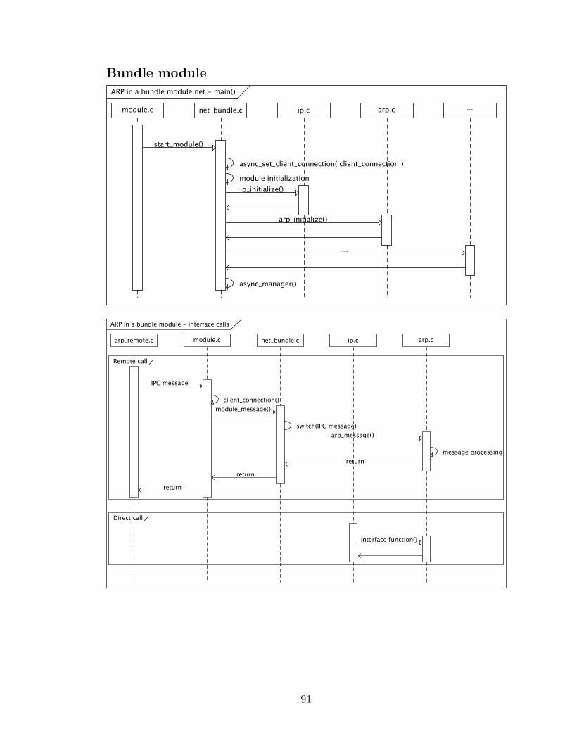
Bundle module
91
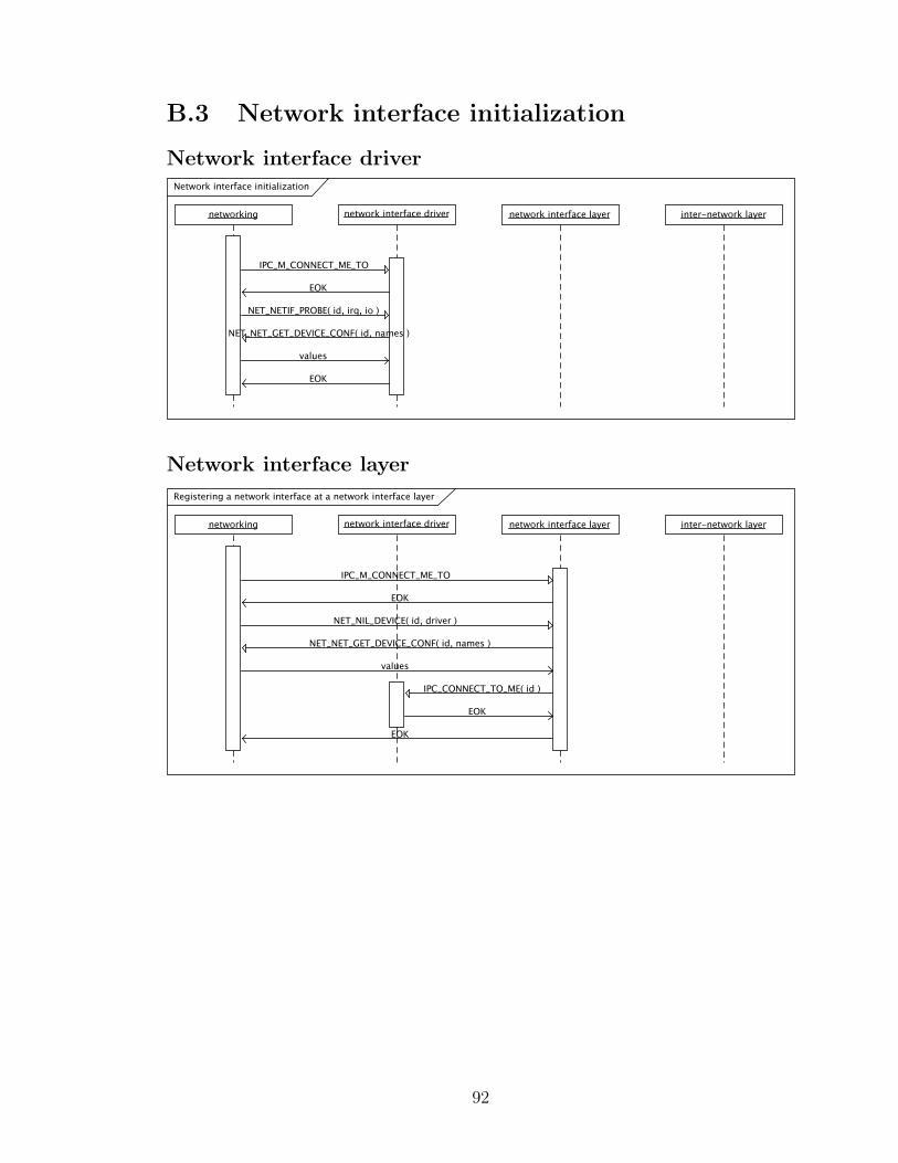
B.3 Network interface initialization
Network interface driver
Network interface layer
92
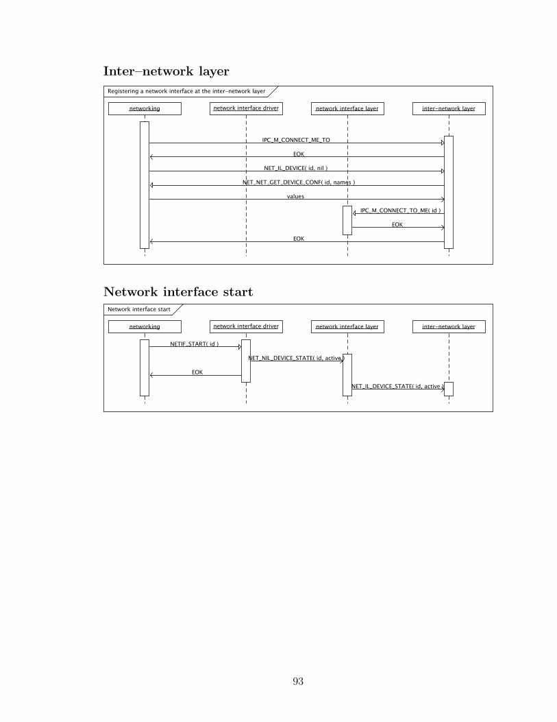
Inter–network layer
Network interface start
93
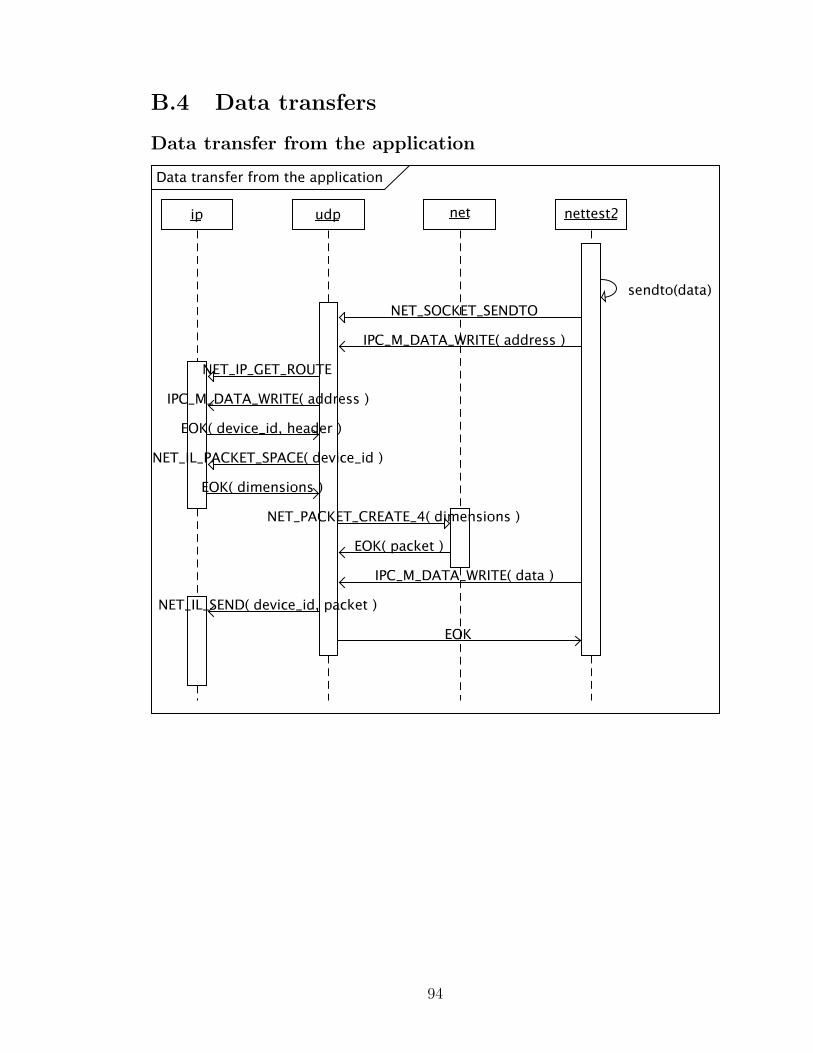
B.4 Data transfers
Data transfer from the application
94
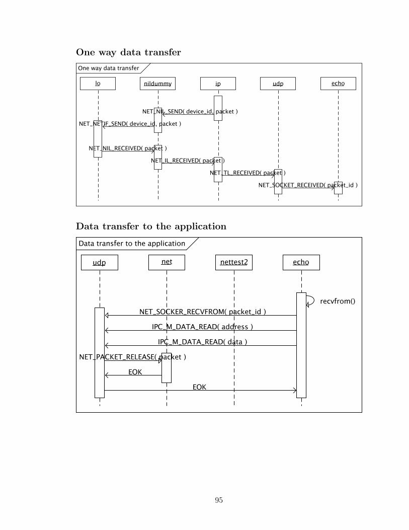
One way data transfer
Data transfer to the application
95