NetworkAIR FM DX Precision Air Conditioner · NetworkAIR FM DX Installation i ... Cooling tower...
60
Installation NetworkAIR ® FM DX Precision Air Conditioner 60 Hz ACFM200 Series ACFM400 Series
Transcript of NetworkAIR FM DX Precision Air Conditioner · NetworkAIR FM DX Installation i ... Cooling tower...
Installation
NetworkAIR® FM DXPrecision Air Conditioner
60 HzACFM200 SeriesACFM400 Series


Contents
General Information........................................................ 1Overview . . . . . . . . . . . . . . . . . . . . . . . . . . . . . . . . . . . . . . . . . . . . . . . . 1
Save these instructions . . . . . . . . . . . . . . . . . . . . . . . . . . . . . . . . 1Intended users . . . . . . . . . . . . . . . . . . . . . . . . . . . . . . . . . . . . . . . 1Manual updates . . . . . . . . . . . . . . . . . . . . . . . . . . . . . . . . . . . . . . 1Cooling configurations . . . . . . . . . . . . . . . . . . . . . . . . . . . . . . . . 1Safety symbols that may be used in this manual . . . . . . . . . . . . . 2Cross-reference symbol used in this manual . . . . . . . . . . . . . . . . 2
Safety . . . . . . . . . . . . . . . . . . . . . . . . . . . . . . . . . . . . . . . . . . . . . . . . . . . 3
Modules, Systems, and Groups. . . . . . . . . . . . . . . . . . . . . . . . . . . . . . 4Module . . . . . . . . . . . . . . . . . . . . . . . . . . . . . . . . . . . . . . . . . . . . 4System . . . . . . . . . . . . . . . . . . . . . . . . . . . . . . . . . . . . . . . . . . . . 4Group . . . . . . . . . . . . . . . . . . . . . . . . . . . . . . . . . . . . . . . . . . . . . 4
Inspecting the Equipment . . . . . . . . . . . . . . . . . . . . . . . . . . . . . . . . . . 5Filing a claim . . . . . . . . . . . . . . . . . . . . . . . . . . . . . . . . . . . . . . . . 5
Storing the Equipment Before Installation . . . . . . . . . . . . . . . . . . . . . 5
Moving the Equipment . . . . . . . . . . . . . . . . . . . . . . . . . . . . . . . . . . . . . 5Moving the equipment through door openings . . . . . . . . . . . . . . . 5Move the equipment to its final location . . . . . . . . . . . . . . . . . . . . 6
Model Identification ........................................................ 6
Inventory.......................................................................... 7Door locks . . . . . . . . . . . . . . . . . . . . . . . . . . . . . . . . . . . . . . . . . . 7
NetworkAIR FM DX Installation i
Component Identification ............................................... 8Downflow . . . . . . . . . . . . . . . . . . . . . . . . . . . . . . . . . . . . . . . . . . .8Upflow . . . . . . . . . . . . . . . . . . . . . . . . . . . . . . . . . . . . . . . . . . . . .9Electrical panel components . . . . . . . . . . . . . . . . . . . . . . . . . . .10User interface box . . . . . . . . . . . . . . . . . . . . . . . . . . . . . . . . . . .11Optional sub-base assembly (upflow) . . . . . . . . . . . . . . . . . . . . .11Optional sub-base assembly (downflow) . . . . . . . . . . . . . . . . . .12Optional floorstand (downflow) . . . . . . . . . . . . . . . . . . . . . . . . .12Optional plenum—supply (upflow) . . . . . . . . . . . . . . . . . . . . . . .13Optional plenum—return (downflow) . . . . . . . . . . . . . . . . . . . . .13Optional flooded receiver . . . . . . . . . . . . . . . . . . . . . . . . . . . . . .13Optional pump packages . . . . . . . . . . . . . . . . . . . . . . . . . . . . . .14
Room Preparation ......................................................... 15Incoming power supply requirements . . . . . . . . . . . . . . . . . . . . .15Supporting the equipment . . . . . . . . . . . . . . . . . . . . . . . . . . . . .15Air distribution . . . . . . . . . . . . . . . . . . . . . . . . . . . . . . . . . . . . . .15
Piping Diagrams ............................................................ 16Air-cooled . . . . . . . . . . . . . . . . . . . . . . . . . . . . . . . . . . . . . . . . .16Water-cooled . . . . . . . . . . . . . . . . . . . . . . . . . . . . . . . . . . . . . . .17Glycol-cooled with single-pump package . . . . . . . . . . . . . . . . . .18Glycol-cooled with dual-pump package . . . . . . . . . . . . . . . . . . .19
Weights and Dimensions.............................................. 20Weights . . . . . . . . . . . . . . . . . . . . . . . . . . . . . . . . . . . . . . . . . . . . . . . . 20
Dimensions . . . . . . . . . . . . . . . . . . . . . . . . . . . . . . . . . . . . . . . . . . . . . 20Packaged with shipping crate . . . . . . . . . . . . . . . . . . . . . . . . . . .20Doors, panels, and main circuit breaker removed . . . . . . . . . . . .21Downflow . . . . . . . . . . . . . . . . . . . . . . . . . . . . . . . . . . . . . . . . . .22Upflow . . . . . . . . . . . . . . . . . . . . . . . . . . . . . . . . . . . . . . . . . . . .22Piping access location in bottom pan—top view . . . . . . . . . . . .23Pump packages . . . . . . . . . . . . . . . . . . . . . . . . . . . . . . . . . . . . .24
NetworkAIR FM DX Installationii
Installation......................................................................25Removing the Doors and Panels . . . . . . . . . . . . . . . . . . . . . . . . . . . .25
Removing the outer front doors . . . . . . . . . . . . . . . . . . . . . . . . . 25Removing the center front door . . . . . . . . . . . . . . . . . . . . . . . . . 25Removing the front fascia . . . . . . . . . . . . . . . . . . . . . . . . . . . . . 26Removing the kick panel . . . . . . . . . . . . . . . . . . . . . . . . . . . . . . 26Removing and installing the side panels . . . . . . . . . . . . . . . . . . 27Removing the rear panels . . . . . . . . . . . . . . . . . . . . . . . . . . . . . 27
Removing the Main Circuit Breaker. . . . . . . . . . . . . . . . . . . . . . . . . .28Removing and installing the main circuit breaker . . . . . . . . . . . . 28
Positioning the Equipment . . . . . . . . . . . . . . . . . . . . . . . . . . . . . . . . .29Service access . . . . . . . . . . . . . . . . . . . . . . . . . . . . . . . . . . . . . 29Rigging . . . . . . . . . . . . . . . . . . . . . . . . . . . . . . . . . . . . . . . . . . . 29
Stabilizing the Equipment. . . . . . . . . . . . . . . . . . . . . . . . . . . . . . . . . .30Placing the equipment on a floorstand (Optional) . . . . . . . . . . . . 30
Plenums and Ducting . . . . . . . . . . . . . . . . . . . . . . . . . . . . . . . . . . . . .31Installing a discharge plenum . . . . . . . . . . . . . . . . . . . . . . . . . . 31
Outdoor Heat Exchanger (OHE) . . . . . . . . . . . . . . . . . . . . . . . . . . . . .32
Flooded Receiver. . . . . . . . . . . . . . . . . . . . . . . . . . . . . . . . . . . . . . . . .32Installing the flooded receiver . . . . . . . . . . . . . . . . . . . . . . . . . . 32
Pump Packages. . . . . . . . . . . . . . . . . . . . . . . . . . . . . . . . . . . . . . . . . .33
Expansion Tank. . . . . . . . . . . . . . . . . . . . . . . . . . . . . . . . . . . . . . . . . .33
Mechanical Connections . . . . . . . . . . . . . . . . . . . . . . . . . . . . . . . . . .33Refrigeration piping . . . . . . . . . . . . . . . . . . . . . . . . . . . . . . . . . . 33Incorrect and correct routing of refrigeration lines . . . . . . . . . . . 34Fitting losses . . . . . . . . . . . . . . . . . . . . . . . . . . . . . . . . . . . . . . . 35Water/glycol . . . . . . . . . . . . . . . . . . . . . . . . . . . . . . . . . . . . . . . 36Economizer automatic coolant isolation valve (optional) . . . . . . 36Piping connections . . . . . . . . . . . . . . . . . . . . . . . . . . . . . . . . . . 38
NetworkAIR FM DX Installation iii

Electrical Connections. . . . . . . . . . . . . . . . . . . . . . . . . . . . . . . . . . . . 40Control connections . . . . . . . . . . . . . . . . . . . . . . . . . . . . . . . . . .40OHE connections . . . . . . . . . . . . . . . . . . . . . . . . . . . . . . . . . . . .41Input and output connections—PCIOM . . . . . . . . . . . . . . . . . . . .42Communication connections . . . . . . . . . . . . . . . . . . . . . . . . . . .43DIP switch configuration . . . . . . . . . . . . . . . . . . . . . . . . . . . . . .44Remote temperature and relative humidity sensor . . . . . . . . . . .44Building Management System connections . . . . . . . . . . . . . . . .45Glycol system electrical connections . . . . . . . . . . . . . . . . . . . . .46Remote condenser electrical connections . . . . . . . . . . . . . . . . .47Main power connections . . . . . . . . . . . . . . . . . . . . . . . . . . . . . .48
Warranty......................................................................... 49One-Year Factory Warranty . . . . . . . . . . . . . . . . . . . . . . . . . . . . . . . . 49
Terms of warranty . . . . . . . . . . . . . . . . . . . . . . . . . . . . . . . . . . .49Non-transferable warranty . . . . . . . . . . . . . . . . . . . . . . . . . . . . .49Exclusions . . . . . . . . . . . . . . . . . . . . . . . . . . . . . . . . . . . . . . . . .49Warranty claims . . . . . . . . . . . . . . . . . . . . . . . . . . . . . . . . . . . . .50
Warranty Procedures . . . . . . . . . . . . . . . . . . . . . . . . . . . . . . . . . . . . . 51Claims . . . . . . . . . . . . . . . . . . . . . . . . . . . . . . . . . . . . . . . . . . . .51Parts . . . . . . . . . . . . . . . . . . . . . . . . . . . . . . . . . . . . . . . . . . . . .51
NetworkAIR FM DX Installationiv
General Information
OverviewSave these instructions
This manual contains important instructions that must be followed during the installation of this equipment.
Intended users
This manual is intended for American Power Conversion (APC) authorized personnel. It provides component specifications and instructions for installing and commissioning the equipment.
Manual updates
Check for updates to this manual on the APC Web site, www.apc.com/support. Click on the User Manuals link and enter the manual part number or SKU for your equipment in the search field. See the back cover of this manual for the part number.
Cooling configurations
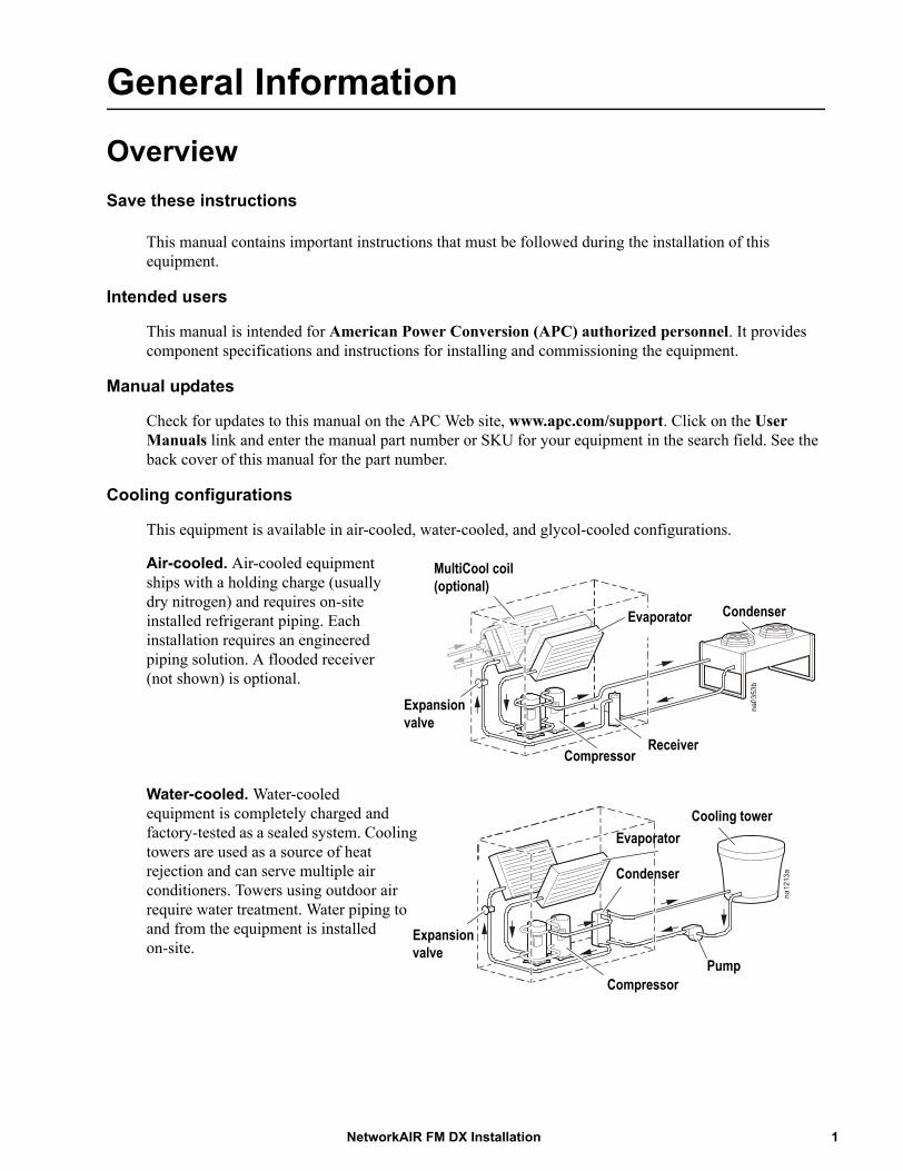
This equipment is available in air-cooled, water-cooled, and glycol-cooled configurations.
Air-cooled. Air-cooled equipment ships with a holding charge (usually dry nitrogen) and requires on-site installed refrigerant piping. Each installation requires an engineered piping solution. A flooded receiver (not shown) is optional.
Water-cooled. Water-cooled equipment is completely charged and factory-tested as a sealed system. Cooling towers are used as a source of heat rejection and can serve multiple air conditioners. Towers using outdoor air require water treatment. Water piping to and from the equipment is installed on-site.
MultiCool coil(optional)
Condenser
ReceiverCompressor
Expansionvalve
Evaporator
na1213a
Cooling tower
PumpCompressor
Evaporator
Condenser
Expansionvalve
1NetworkAIR FM DX Installation
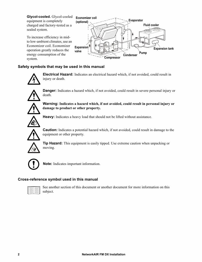
Glycol-cooled. Glycol-cooled equipment is completely charged and factory-tested as a sealed system.
To increase efficiency in mid- to low-ambient climates, use an Economizer coil. Economizer operation greatly reduces the energy consumption of the system.
Safety symbols that may be used in this manual
Electrical Hazard: Indicates an electrical hazard which, if not avoided, could result in injury or death.
Danger: Indicates a hazard which, if not avoided, could result in severe personal injury or death.
Warning: Indicates a hazard which, if not avoided, could result in personal injury or damage to product or other property.
Heavy: Indicates a heavy load that should not be lifted without assistance.
Caution: Indicates a potential hazard which, if not avoided, could result in damage to the equipment or other property.
Tip Hazard: This equipment is easily tipped. Use extreme caution when unpacking or moving.
Note: Indicates important information.
Cross-reference symbol used in this manual
See another section of this document or another document for more information on this subject.
Economizer coil(optional)
Fluid coolerEvaporator
Expansionvalve
CompressorCondenser Pump
Expansion tank
NetworkAIR FM DX Installation2
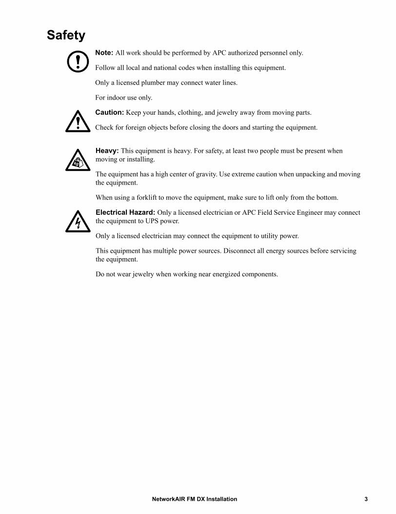
SafetyNote: All work should be performed by APC authorized personnel only.
Follow all local and national codes when installing this equipment.
Only a licensed plumber may connect water lines.
For indoor use only.
Caution: Keep your hands, clothing, and jewelry away from moving parts.
Check for foreign objects before closing the doors and starting the equipment.
Heavy: This equipment is heavy. For safety, at least two people must be present when moving or installing.
The equipment has a high center of gravity. Use extreme caution when unpacking and moving the equipment.
When using a forklift to move the equipment, make sure to lift only from the bottom.
Electrical Hazard: Only a licensed electrician or APC Field Service Engineer may connect the equipment to UPS power.
Only a licensed electrician may connect the equipment to utility power.
This equipment has multiple power sources. Disconnect all energy sources before servicing the equipment.
Do not wear jewelry when working near energized components.
3NetworkAIR FM DX Installation
Modules, Systems, and GroupsNetworkAIR Modules and Expansion Modules can be combined electronically to create Systems and Groups.
Module
A Module is an independent Computer Room Air Conditioner (CRAC) which operates based on its own temperature and humidity sensors.
System
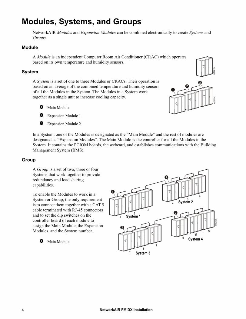
A System is a set of one to three Modules or CRACs. Their operation is based on an average of the combined temperature and humidity sensors of all the Modules in the System. The Modules in a System work together as a single unit to increase cooling capacity.
In a System, one of the Modules is designated as the “Main Module” and the rest of modules are designated as “Expansion Modules”. The Main Module is the controller for all the Modules in the System. It contains the PCIOM boards, the webcard, and establishes communications with the Building Management System (BMS).
Group
A Group is a set of two, three or four Systems that work together to provide redundancy and load sharing capabilities.
To enable the Modules to work in a System or Group, the only requirement is to connect them together with a CAT 5 cable terminated with RJ-45 connectors and to set the dip switches on the controller board of each module to assign the Main Module, the Expansion Modules, and the System number..
Main Module
Expansion Module 1
Expansion Module 2
Main Module
na0269a
na0270a
System 1
System 3
System 4
System 2
NetworkAIR FM DX Installation4
Inspecting the EquipmentYour equipment has been tested and inspected for quality assurance prior to shipment from APC. To ensure that the equipment has not been damaged during transit, carefully inspect both the exterior and interior of the equipment immediately upon receipt.
Verify that all parts ordered were received as specified. See “Inventory” on page 7.
Filing a claim
If damage is identified on receipt of the equipment, note the damage on the bill of lading and file a damage claim with the shipping company. Contact APC for information on filing a claim with the shipping company. The shipping claim must be filed at the receiving end of the delivery.
Note: In case of shipping damage, do not operate the equipment. Keep all packaging for inspection by the shipper and call APC at one of the numbers listed on the back cover of this manual.
Storing the Equipment Before InstallationCaution: Leaving the equipment uncovered and exposed to the elements can cause damage and will void the factory warranty.
Moving the EquipmentMoving the equipment through door openings
Depending upon your installation, you may need to modify the equipment to fit through smaller door openings.
See the dimensional drawing and “Dimensions” on page 20 to determine if modification is necessary.
If modifications are necessary, you can decrease the width of the equipment by removing the front kick panel, hard points, and main circuit breakers.
See “Removing the Doors and Panels” on page 25 for more information.
5NetworkAIR FM DX Installation

Move the equipment to its final location
Tip Hazard: Use extreme caution to prevent tipping when unpacking or moving the equipment to its final location.
Moving the equipment requires two people for safety. Push the equipment from the front only.
Warning: When using a forklift to move the equipment, make sure to lift only from the bottom. Do not use a forklift if the equipment has been removed from its pallet.
Heavy: Do not attempt to move the equipment without assistance. Moving this equipment requires two people.
Select the appropriate tools for moving the equipment. Each site will have different needs and considerations.
Model IdentificationThe model number is on the outside of the shipping carton and on the ratings label located on the lid of the electrical box. Use the table below to verify that the equipment is the correct size and voltage.
Pallet jack Furniture dollies (2)
Forklift Roller bars Wheeled lever
Model Voltage Air Pattern Configuration RefrigerantReheat
(Standard)Humidification
(Standard)
ACFM XX X XX R-2220 = 208-230/3/60
0 = Downflow A = Air-cooled SCR Electric
Steam Canister (Replaceable)
40 = 480/3/60
1 = Upflow Front Return
AM = Air-cooled with MultiCool
10kW
G = Glycol-cooledGE = Glycol-cooled with EconomizerW = Water-cooled
NetworkAIR FM DX Installation6
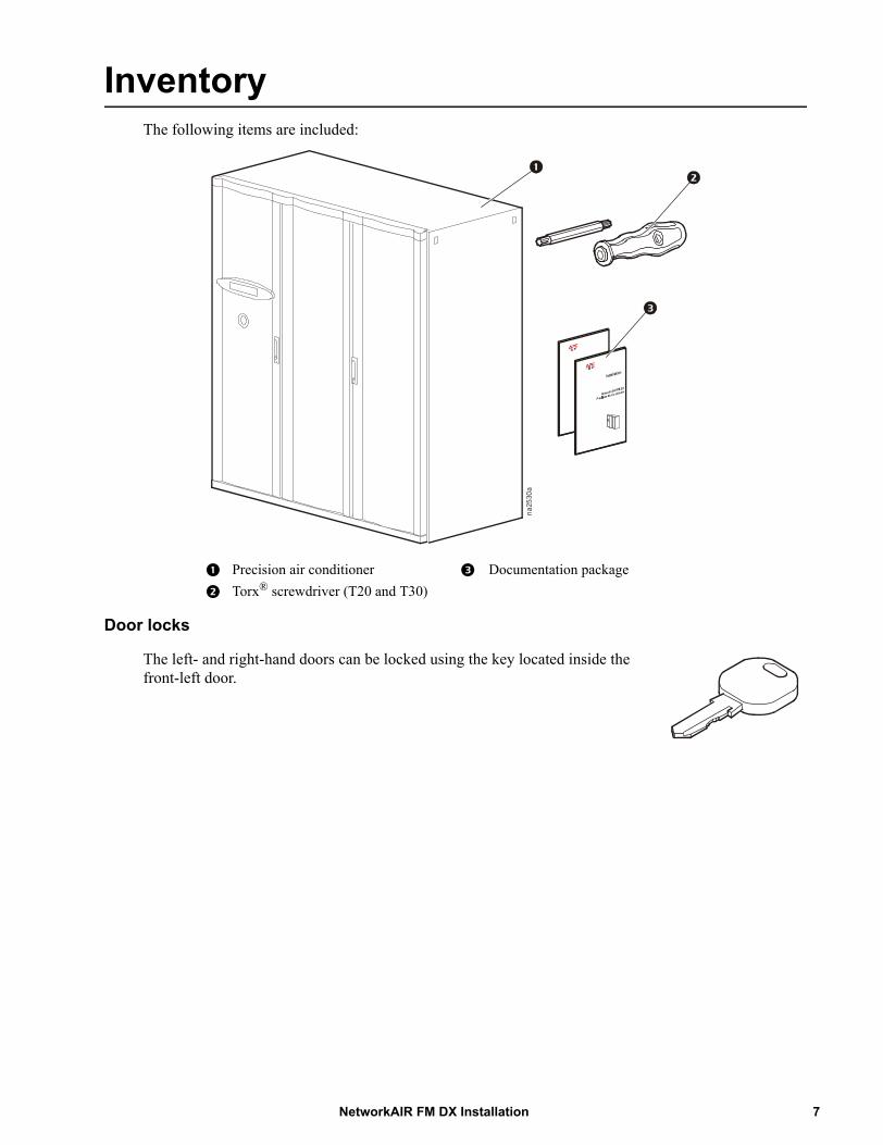
InventoryThe following items are included:
Door locks
The left- and right-hand doors can be locked using the key located inside the front-left door.
Precision air conditioner Documentation package
Torx® screwdriver (T20 and T30)
na2530a
7NetworkAIR FM DX Installation
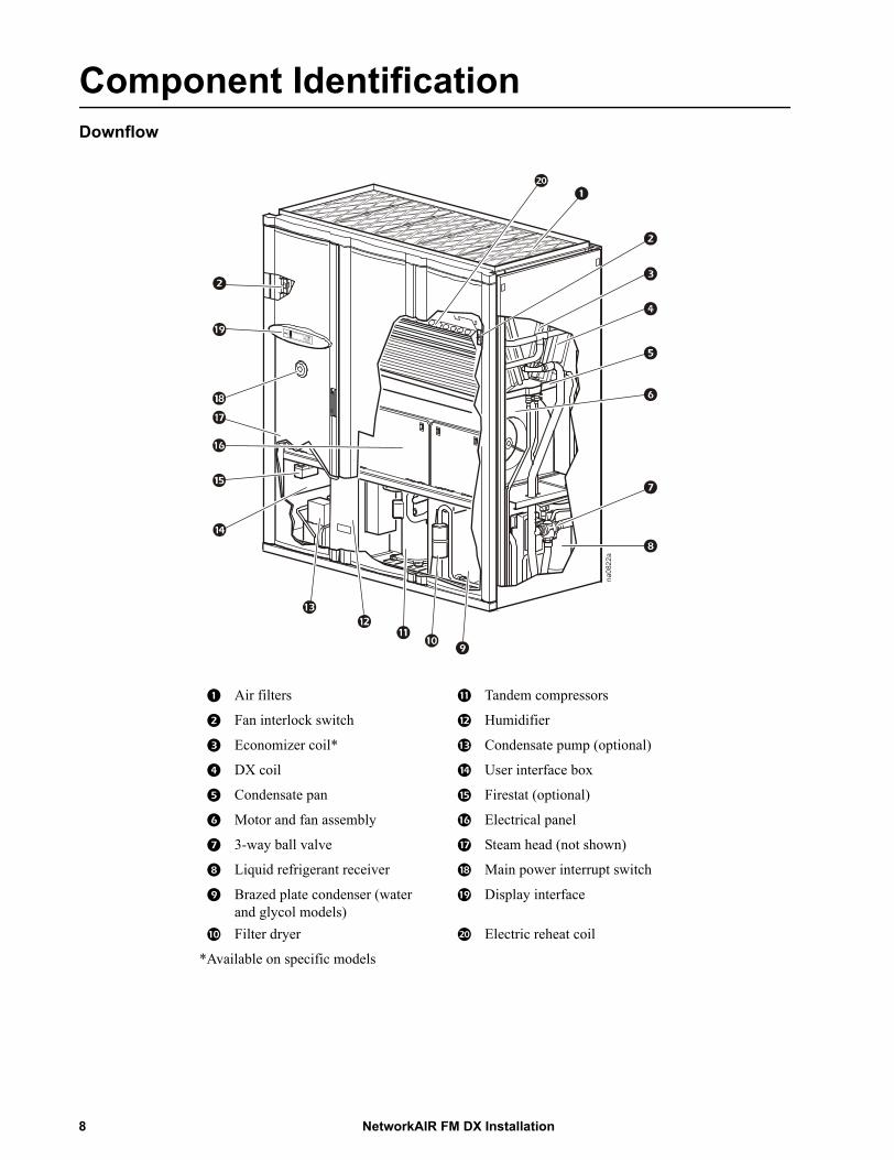
Component IdentificationDownflow
Air filters Tandem compressors
Fan interlock switch Humidifier
Economizer coil* Condensate pump (optional)
DX coil User interface box
Condensate pan Firestat (optional)
Motor and fan assembly Electrical panel
3-way ball valve Steam head (not shown)
Liquid refrigerant receiver Main power interrupt switch
Brazed plate condenser (water and glycol models)
Display interface
Filter dryer Electric reheat coil
*Available on specific models
na0822a
NetworkAIR FM DX Installation8
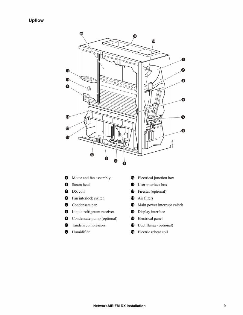
Upflow
Motor and fan assembly Electrical junction box
Steam head User interface box
DX coil Firestat (optional)
Fan interlock switch Air filters
Condensate pan Main power interrupt switch
Liquid refrigerant receiver Display interface
Condensate pump (optional) Electrical panel
Tandem compressors Duct flange (optional)
Humidifier Electric reheat coil
na0814a
9NetworkAIR FM DX Installation
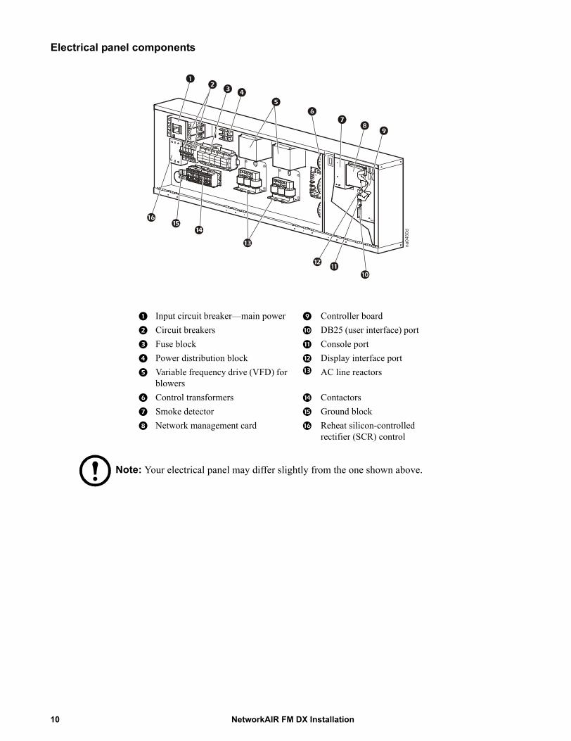
Electrical panel components
Note: Your electrical panel may differ slightly from the one shown above.
Input circuit breaker—main power Controller board
Circuit breakers DB25 (user interface) port
Fuse block Console port
Power distribution block Display interface port
Variable frequency drive (VFD) for blowers
AC line reactors
Control transformers Contactors
Smoke detector Ground block
Network management card Reheat silicon-controlled rectifier (SCR) control
na0450d
NetworkAIR FM DX Installation10
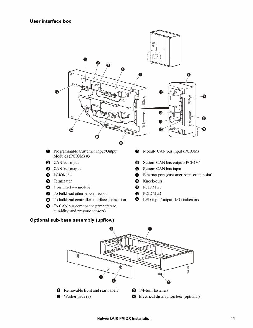
User interface box
Optional sub-base assembly (upflow)
Programmable Customer Input/Output Modules (PCIOM) #3
Module CAN bus input (PCIOM)
CAN bus input System CAN bus output (PCIOM)
CAN bus output System CAN bus input
PCIOM #4 Ethernet port (customer connection point)
Terminator Knock-outs
User interface module PCIOM #1
To bulkhead ethernet connection PCIOM #2
To bulkhead controller interface connection LED input/output (I/O) indicators
To CAN bus component (temperature, humidity, and pressure sensors)
Removable front and rear panels 1/4-turn fasteners
Washer pads (6) Electrical distribution box (optional)
na0252a
11NetworkAIR FM DX Installation

Optional sub-base assembly (downflow)
Optional floorstand (downflow)
Removable rear panel Washer pads (6)
Rear-piping access chase Discharge air panel
Utility access
Air blocks Pad
Joining bracket Turning vane
Adjustable legs Turning vane extension
Pedestal Electrical distribution box (optional)
na0875a
NetworkAIR FM DX Installation12
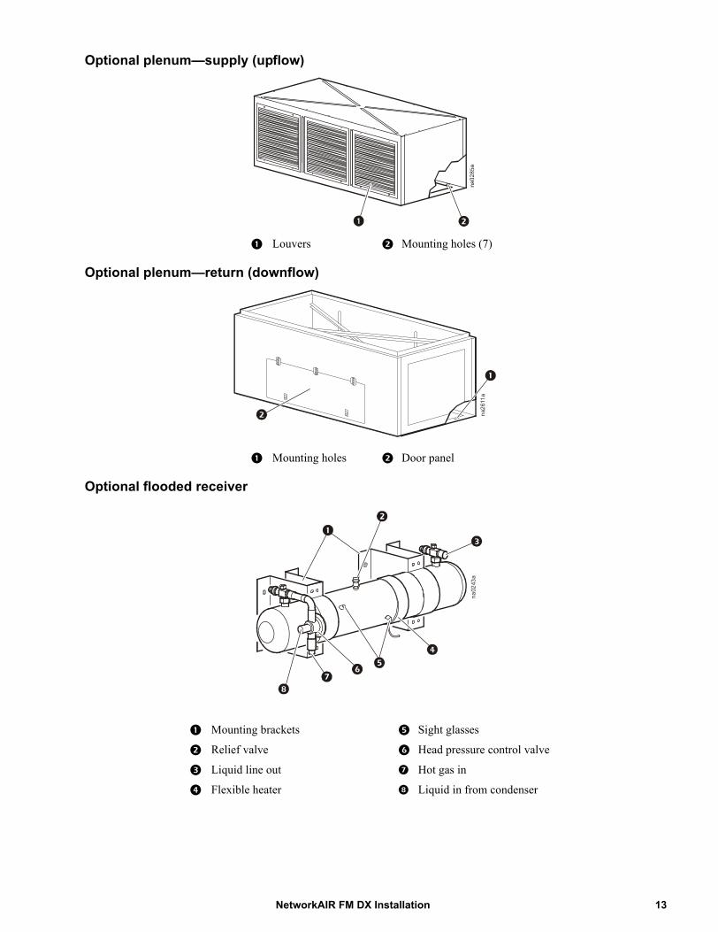
Optional plenum—supply (upflow)
Optional plenum—return (downflow)
Optional flooded receiver
Louvers Mounting holes (7)
Mounting holes Door panel
Mounting brackets Sight glasses
Relief valve Head pressure control valve
Liquid line out Hot gas in
Flexible heater Liquid in from condenser
na2611a
na0243a
13NetworkAIR FM DX Installation

Optional pump packages
Single-pump package Disconnect switch
Dual-pump package Ground lug
Pump control access Circuit breakers
Discharge port Overload relay
Suction port Contactor
13 mm (1/2 in) mounting holes (4)
Terminal board
Disconnect switch handle Communication access knockouts, 13 mm (1/2 in) and 20 mm (3/4 in)
Power entry knockouts, 20 mm (3/4 in) and 25 mm (1in)
Pump reset switch
na1209a
NetworkAIR FM DX Installation14

Room PreparationDuring the design of the data center, consider ease of entry for the equipment, floor loading factors, and accessibility to piping and wiring.Seal the room with a vapor barrier to minimize moisture infiltration. (Polyethylene film is recommended for ceiling and wall applications.) Apply rubber- or plastic-based paints to concrete walls and floors.Insulate the room to minimize the influence of exterior heat loads. Reduce fresh air to the minimum required by local and national codes and regulations. Fresh air imposes extreme load variation on the cooling equipment from summer to winter as well as causing increased system operating costs.Raised floor. A computer room with a raised floor plenum for air distribution should have at least 457 mm (18 in) of clear space between the false floor and sub-floor. Pay special attention to the location of pipe chases, electrical conduits, and other under-floor obstructions. These objects can block air circulation and increase air pressure drops, creating a condition which reduces system efficiency and causes possible hot spots in the room.
Incoming power supply requirements
Note: The equipment requires three-phase electrical service. Electrical service must conform to national and local electrical codes and regulations. The equipment must be grounded.
Supporting the equipment
Sub-base. When using upflow equipment, a sub-base is required to allow routing of supply and discharge elements, such as refrigerant, water, power, and drain lines.
Floorstand. Downflow discharge equipment can be installed directly on the raised floor after ensuring that the floor can support it. A floorstand can be used where the floor cannot support the equipment.
Note: Consult your raised floor manufacturer for weight capacities if you are installing the equipment directly on the raised floor.
Air distribution
Downflow discharge. If the installation location has a raised floor, the space between the raised floor and sub-floor can be used as an air distribution plenum.
• When installing equipment on a raised floor, maintain sufficient free area to allow proper air movement.
• Consider under-floor obstructions that might prevent conditioned air from being properly distributed throughout the room.
• Install an adequate number of perforated floor tiles to allow for the predetermined air distribution in the conditioned space. Install more perforated tiles near heavier heat loads.
Upflow discharge. In rooms designed for upflow discharge systems, air is distributed through a supply duct or through a discharge plenum into the conditioned space. The same location considerations for a downflow discharge system also apply to upflow discharge systems.
Note: All equipment is designed for a maximum of 1016 Pa (0.3 in) of external static pressure.
15NetworkAIR FM DX Installation
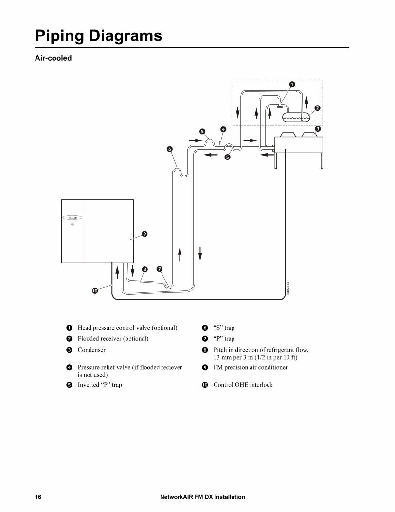
Piping DiagramsAir-cooled
Head pressure control valve (optional) “S” trap
Flooded receiver (optional) “P” trap
Condenser Pitch in direction of refrigerant flow, 13 mm per 3 m (1/2 in per 10 ft)
Pressure relief valve (if flooded reciever is not used)
FM precision air conditioner
Inverted “P” trap Control OHE interlock
na0266a
NetworkAIR FM DX Installation16
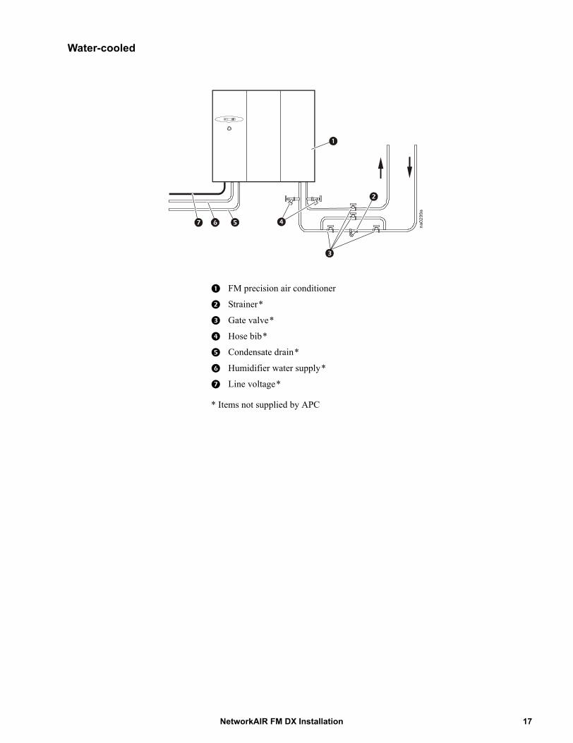
Water-cooled
FM precision air conditioner
Strainer*
Gate valve*
Hose bib*
Condensate drain*
Humidifier water supply*
Line voltage*
* Items not supplied by APC
17NetworkAIR FM DX Installation
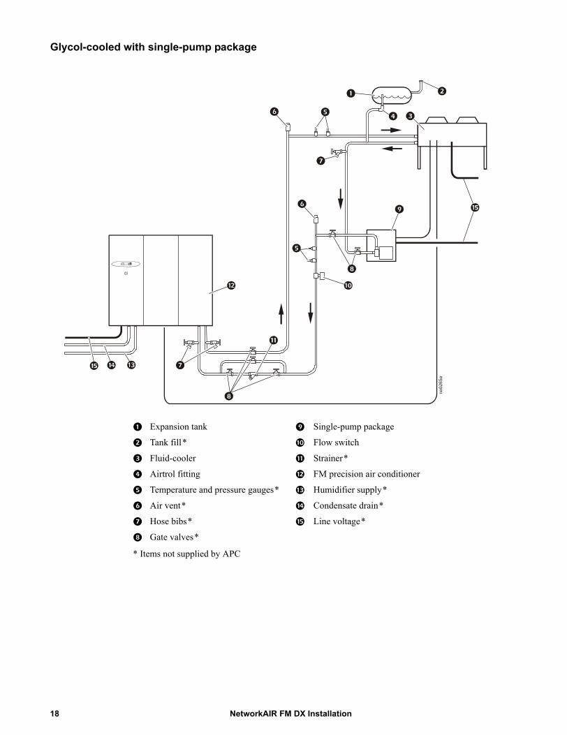
Glycol-cooled with single-pump package
Expansion tank Single-pump package
Tank fill* Flow switch
Fluid-cooler Strainer*
Airtrol fitting FM precision air conditioner
Temperature and pressure gauges* Humidifier supply*
Air vent* Condensate drain*
Hose bibs* Line voltage*
Gate valves*
* Items not supplied by APC
NetworkAIR FM DX Installation18
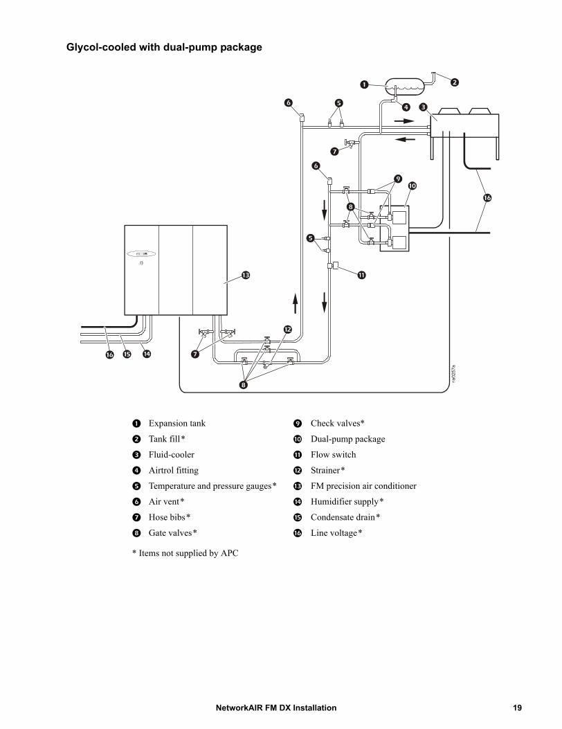
Glycol-cooled with dual-pump package
Expansion tank Check valves*
Tank fill* Dual-pump package
Fluid-cooler Flow switch
Airtrol fitting Strainer*
Temperature and pressure gauges* FM precision air conditioner
Air vent* Humidifier supply*
Hose bibs* Condensate drain*
Gate valves* Line voltage*
* Items not supplied by APC
19NetworkAIR FM DX Installation
Weights and Dimensions
Weights
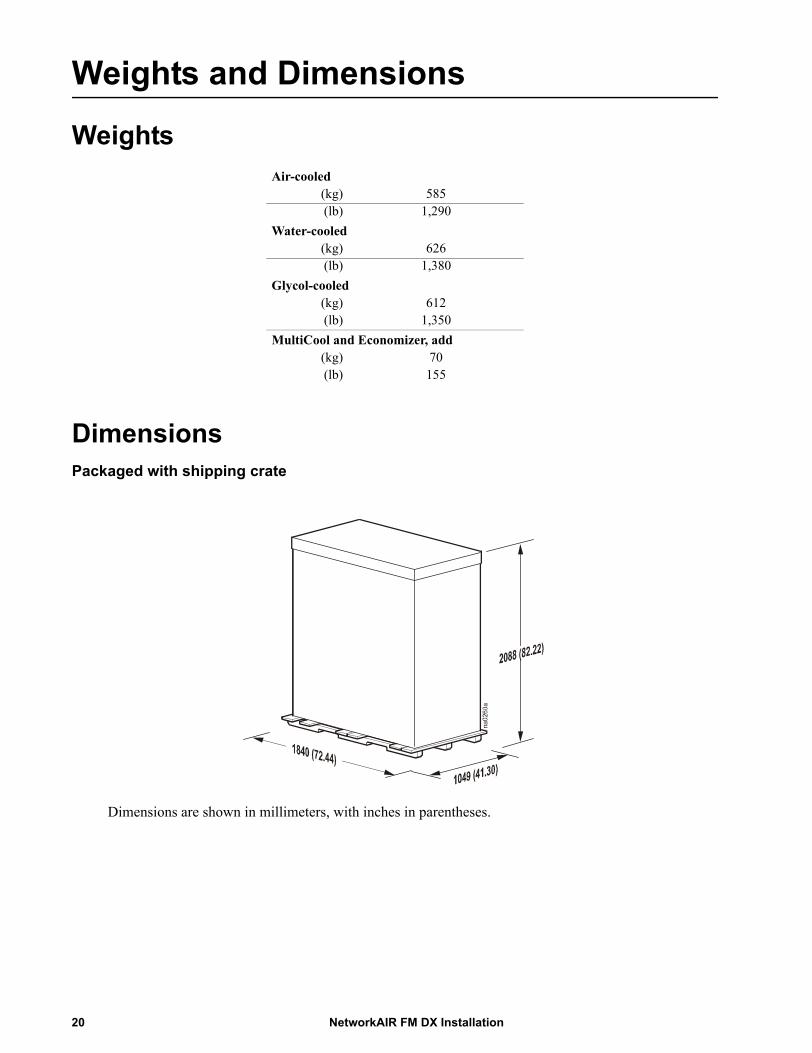
DimensionsPackaged with shipping crate
Dimensions are shown in millimeters, with inches in parentheses.
Air-cooled(kg) 585 (lb) 1,290
Water-cooled(kg) 626 (lb) 1,380
Glycol-cooled(kg) 612 (lb) 1,350
MultiCool and Economizer, add(kg) 70 (lb) 155
NetworkAIR FM DX Installation20
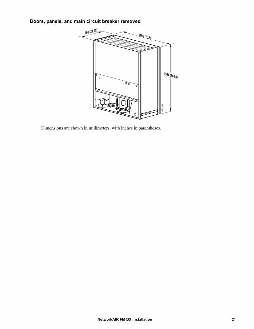
Doors, panels, and main circuit breaker removed
Dimensions are shown in millimeters, with inches in parentheses.
21NetworkAIR FM DX Installation
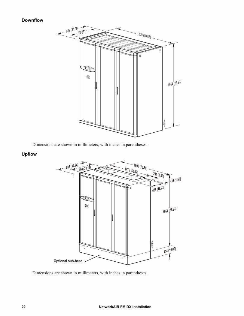
Downflow
Dimensions are shown in millimeters, with inches in parentheses.
Upflow
Dimensions are shown in millimeters, with inches in parentheses.
na0214a
Optional sub-base
NetworkAIR FM DX Installation22
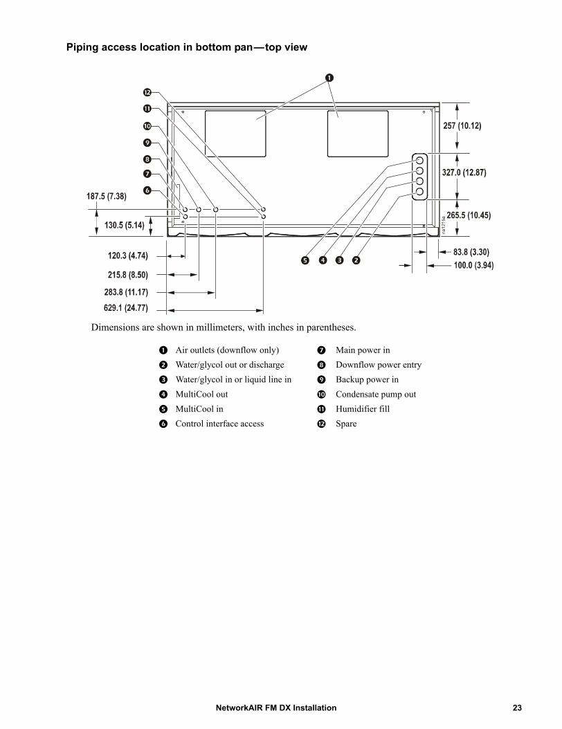
Piping access location in bottom pan—top view
Dimensions are shown in millimeters, with inches in parentheses.
Air outlets (downflow only) Main power in
Water/glycol out or discharge Downflow power entry
Water/glycol in or liquid line in Backup power in
MultiCool out Condensate pump out
MultiCool in Humidifier fill
Control interface access Spare
23NetworkAIR FM DX Installation
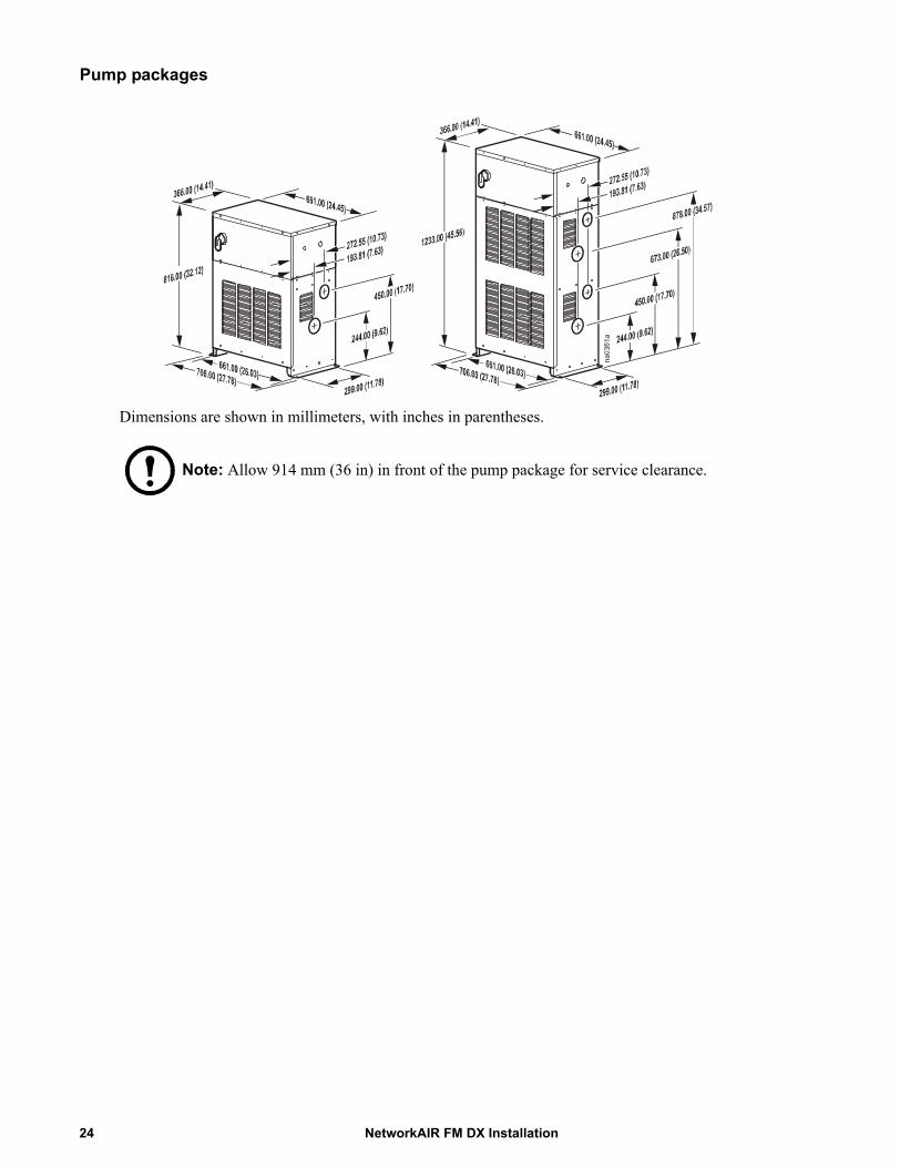
Pump packages
Dimensions are shown in millimeters, with inches in parentheses.
Note: Allow 914 mm (36 in) in front of the pump package for service clearance.
NetworkAIR FM DX Installation24

Installation
Removing the Doors and PanelsWhen moving the equipment, it may be necessary to modify it to fit through smaller door openings. Decrease the depth by removing the front doors, front fascia, kick panel, rear panels, and main circuit breaker.
Heavy: Doors and panels are heavy. For safety, have at least two people lift and move them during removal or installation.
Caution: The equipment must stay upright at all times. Tilting the equipment more than a few inches from the vertical may cause internal damage.
Removing the outer front doors
1. Open the door.2. Before removing the left door,
remove the display interface and the main power interrupt switch connections as shown.
3. Pull down on the spring-loaded hinge pin located in the top of the door. Tilt the door forward and lift up to release it from the lower hinge pin.
Removing the center front door
1. Open the left- and right-hand doors to gain access to the center panel release mechanisms.
2. Pull down on the spring-loaded hinge pins located in the top of the door. Tilt the door forward and lift up to release it from the lower hinge pin.
25NetworkAIR FM DX Installation
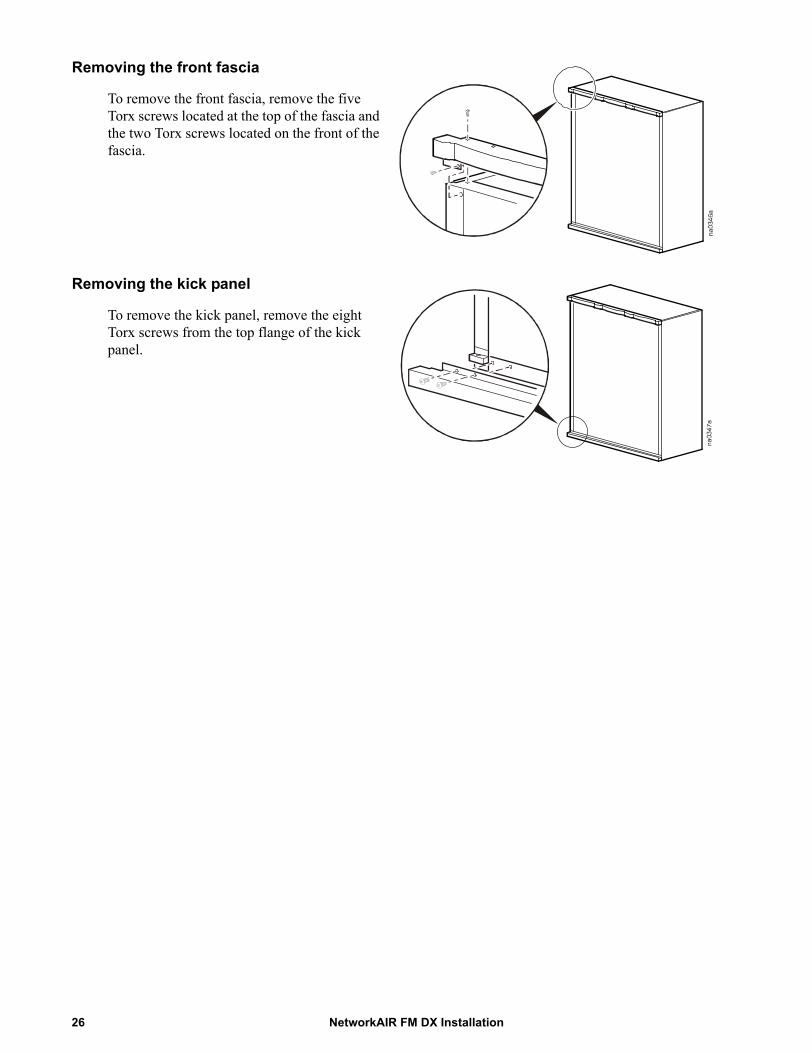
Removing the front fascia
To remove the front fascia, remove the five Torx screws located at the top of the fascia and the two Torx screws located on the front of the fascia.
Removing the kick panel
To remove the kick panel, remove the eight Torx screws from the top flange of the kick panel.
NetworkAIR FM DX Installation26

Removing and installing the side panels
Remove side panels to access internal components or to join equipment.
1. Slide both panel latches down and pull the top of the panel toward you.
2. Lift the panel up and out of the channel located at the bottom of the frame.
3. Reverse this procedure to install the panels.
Removing the rear panels
1. Remove the cap plugs (six per panel).2. Remove the Torx screws (six per panel).
27NetworkAIR FM DX Installation

Removing the Main Circuit BreakerWhen moving the equipment, it may be necessary to modify it to fit through smaller door openings. To decrease the depth of the equipment to 800 mm (31.5 inches), the main circuit breaker, located in the electrical panel, must be removed.
Caution: Before removing any electrical components, be sure to note the orientation of the electrical component and label all wires with their location.
Removing and installing the main circuit breaker
Electrical Hazard: Only authorized APC personnel should remove and replace the main circuit breaker.
1. Mark and disconnect the wires at the main circuit breaker.
2. Remove the main circuit breaker by removing four Torx screws.
3. Reinstall by reversing the above procedure.
na0374a
Caution: When connecting wires to the circuit breaker, torque the terminal screws to the proper value. See torque values marked on the circuit breaker.
NetworkAIR FM DX Installation28
Positioning the EquipmentService access
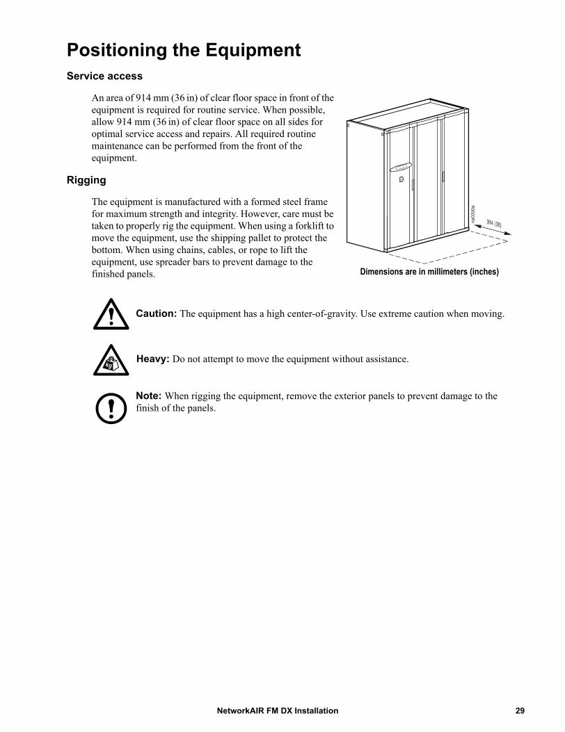
An area of 914 mm (36 in) of clear floor space in front of the equipment is required for routine service. When possible, allow 914 mm (36 in) of clear floor space on all sides for optimal service access and repairs. All required routine maintenance can be performed from the front of the equipment.
Rigging
The equipment is manufactured with a formed steel frame for maximum strength and integrity. However, care must be taken to properly rig the equipment. When using a forklift to move the equipment, use the shipping pallet to protect the bottom. When using chains, cables, or rope to lift the equipment, use spreader bars to prevent damage to the finished panels.
Caution: The equipment has a high center-of-gravity. Use extreme caution when moving.
Heavy: Do not attempt to move the equipment without assistance.
Note: When rigging the equipment, remove the exterior panels to prevent damage to the finish of the panels.
Dimensions are in millimeters (inches)
29NetworkAIR FM DX Installation
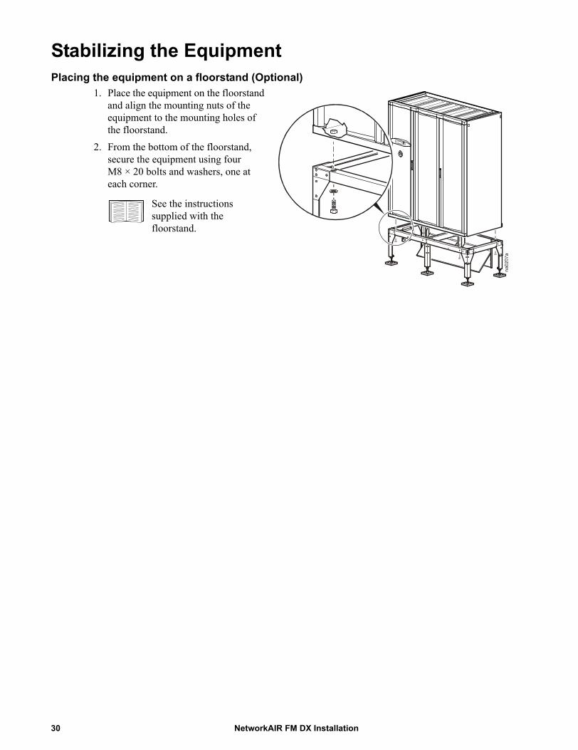
Stabilizing the EquipmentPlacing the equipment on a floorstand (Optional)
1. Place the equipment on the floorstand and align the mounting nuts of the equipment to the mounting holes of the floorstand.
2. From the bottom of the floorstand, secure the equipment using four M8 × 20 bolts and washers, one at each corner.
See the instructions supplied with the floorstand.
NetworkAIR FM DX Installation30
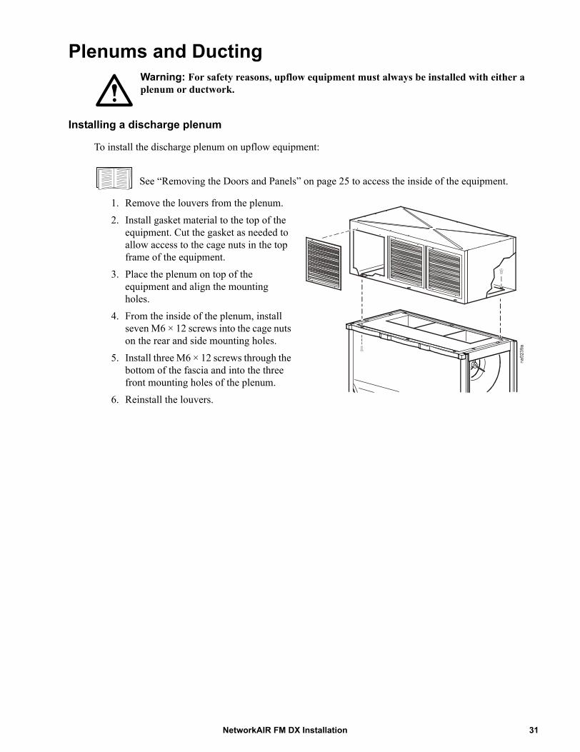
Plenums and DuctingWarning: For safety reasons, upflow equipment must always be installed with either a plenum or ductwork.
Installing a discharge plenum
To install the discharge plenum on upflow equipment:
See “Removing the Doors and Panels” on page 25 to access the inside of the equipment.
1. Remove the louvers from the plenum.2. Install gasket material to the top of the
equipment. Cut the gasket as needed to allow access to the cage nuts in the top frame of the equipment.
3. Place the plenum on top of the equipment and align the mounting holes.
4. From the inside of the plenum, install seven M6 × 12 screws into the cage nuts on the rear and side mounting holes.
5. Install three M6 × 12 screws through the bottom of the fascia and into the three front mounting holes of the plenum.
6. Reinstall the louvers.
31NetworkAIR FM DX Installation
Outdoor Heat Exchanger (OHE)Note: An OHE can be defined as a fluidcooler or condenser, depending on cooling requirements.
Mount the OHE on a level surface with sufficient strength to support the weight of the OHE when fully charged. Use the mounting holes on the heat exchanger to prevent the equipment from shifting during operation.
Before operation, ensure that all heat exchangers satisfy the following requirements:
• Incoming voltages match the nameplate listed on the heat exchanger.• All set screws are secure.• All piping is installed in accordance with applicable codes.• Fan blades turn freely, do not wobble, and are not distorted.• Fan blades rotate in the proper direction.• The relief valve provided with the condenser has been installed.
Provide a method to disconnect main power in order to isolate the heat exchanger during routine service or an emergency.
See the heat exchanger manufacturer installation, operation, and maintenance manuals for proper installation procedures.
Flooded ReceiverInstalling the flooded receiver
Note: A flooded reciever is used only with a condenser.
To attach the flooded receiver to the side of the condenser, see the instructions included with the flooded receiver.
NetworkAIR FM DX Installation32
Pump PackagesThe pump package is suitable for outdoor installation and has been factory-wired with pump and motor circuit breakers. See the pump housing nameplate for electrical information and correct wire sizes. The pump size may have been increased or decreased from the standard pump package because of pressure drop requirements.
Mount the pump package as close as possible to the fluid-cooler. Allow 914 mm (36 in) in front of the pump package for service clearance. The glycol solution should flow from the fluid-cooler to the pump package.
Dual-pump packages. Field-supplied check valves are required on the discharge side of each pump. Install isolation valves to isolate each pump in case of pump failure and pump replacement while the condenser loop is in operation. Locate all temperature control devices for the fluid-cooler fans on the fluid-out header of the fluid-cooler. Typically, on a draw-through fluid-cooler, the bottom header (or the header located at the air-intake side of the fluid-cooler) is where the coolest air is pulled in. These temperature-sensing bulbs must be insulated properly to prevent temperature influences from ambient or solar conditions. Dual pump packages have a factory-supplied, field-installed flow switch used to activate the auto-changeover function on dual pump packages. This flow switch must sense flow on the condenser loop supply coming from the pump discharge.
Expansion TankMount the expansion tank at the highest point in the piping system. Provide a hose bib connection for filling the system.
When plumbing the expansion tank, see “Piping Diagrams” on page 16.
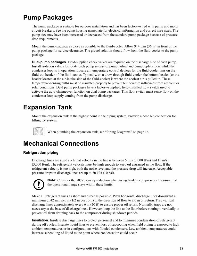
Mechanical ConnectionsRefrigeration piping
Discharge lines are sized such that velocity in the line is between 5 m/s (1,000 ft/m) and 15 m/s(3,000 ft/m). The refrigerant velocity must be high enough to keep oil entrained in the flow. If the refrigerant velocity is too high, both the noise level and the pressure drop will increase. Acceptable pressure drops in discharge lines are up to 70 kPa (10 psi).
Note: Consider the 50% capacity reduction when using tandem compressors to ensure that the operational range stays within these limits.
Make all refrigerant lines as short and direct as possible. Pitch horizontal discharge lines downward a minimum of 42 mm per m (1/2 in per 10 ft) in the direction of flow to aid in oil return. Trap vertical discharge lines approximately every 6 m (20 ft) to ensure proper oil return. Normally, traps are not necessary at the base of discharge lines. However, loop the line to the floor before routing it vertically to prevent oil from draining back to the compressor during shutdown periods.
Insulation. Insulate discharge lines to protect personnel and to minimize condensation of refrigerant during off cycles. Insulate liquid lines to prevent loss of subcooling when field piping is exposed to high ambient temperatures or in configurations with flooded condensers. Low ambient temperatures could increase subcooling of liquid to the point where condensation could occur.
33NetworkAIR FM DX Installation

Air-cooled. The equipment must be connected to a condenser—either a remote outdoor condenser or an indoor centrifugal condenser. Systems with remote outdoor or indoor centrifugal condensers must have discharge and liquid lines from the indoor equipment to the condenser. Install all refrigerant lines in accordance with applicable industry guidelines and state, local, and national codes.
To size lines, see “Recommended line sizes (type L copper)” on page 35.
Calculate an equivalent length based on the actual linear length of the run, including valves and fittings. All fittings should be long-radius to minimize pressure drop.
Incorrect and correct routing of refrigeration lines
NetworkAIR FM DX Installation34

Fitting losses
Fitting losses in equivalent feet of pipe
Recommended line sizes (type L copper)
Size of Pipe in Inches (OD)
Type of Fitting or Valve - Equivalent Length of Pipe in Feet(Screwed, welded, flanged, flared, and brazed connections)
90° Standard*
90° Long Radius** 90° Street* 45°
Standard* 45° Street* Sudden Enlargement, d:D Sudden Contraction, d:D
1:4 1:2 3:4 1:4 1:2 3:47/8 2.0 1.4 3.2 0.9 1.6 2.5 1.5 0.5 1.2 1.0 0.5
1-1/8 2.6 1.7 4.1 1.3 2.1 3.2 2.0 0.7 1.6 1.2 0.71-3/8 3.3 2.3 5.6 1.7 3.0 4.7 3.0 1.0 2.3 1.8 1.0
*R/D approximately equal to 1**R/D approximately equal to 1.5
Equivalent Length m (ft) Line type ACFM
15 (50) Discharge Line (horizontal) 1 1/8Discharge Line (vertical) 7/8Liquid Line 7/8Flooded condenser to receiver** 1 1/8
30 (100) Discharge Line (horizontal) 1 3/8Discharge Line (vertical) 1 1/8Liquid Line 7/8Flooded condenser to receiver** 1 1/8
46 (150) Discharge Line (horizontal) 1 3/8Discharge Line (vertical) 1 1/8Liquid Line 7/8Flooded condenser to receiver** 1 1/8
61 (200)* Discharge Line (horizontal) 1 3/8Discharge Line (vertical) 1 1/8Liquid Line 7/8Flooded condenser to receiver** 1 1/8
* Maximum allowable equivalent length**Applicable with flooded condenser option
Dd D d
35NetworkAIR FM DX Installation
Water/glycol
Use care when identifying the inlets and outlets of the glycol/water-cooled components. Install isolation valves and circuit flow switches as necessary to facilitate proper servicing and flow control for the equipment.
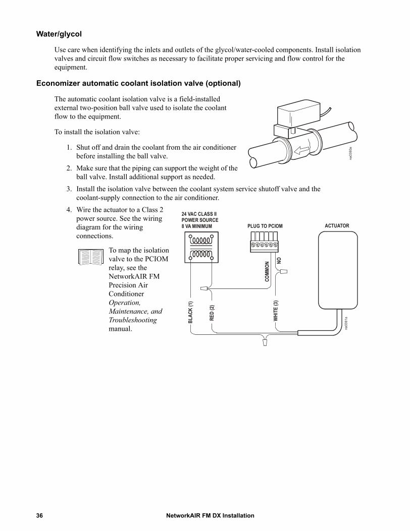
Economizer automatic coolant isolation valve (optional)
The automatic coolant isolation valve is a field-installed external two-position ball valve used to isolate the coolant flow to the equipment.
To install the isolation valve:
1. Shut off and drain the coolant from the air conditioner before installing the ball valve.
2. Make sure that the piping can support the weight of the ball valve. Install additional support as needed.
3. Install the isolation valve between the coolant system service shutoff valve and the coolant-supply connection to the air conditioner.
4. Wire the actuator to a Class 2 power source. See the wiring diagram for the wiring connections.
na0380a
24 VAC CLASS II POWER SOURCE 8 VA MINIMUM PLUG TO PCIOM
COMM
ON
NOW
HITE
(3)
BLAC
K (1
)
RED
(2)
ACTUATOR
na0381a
To map the isolation valve to the PCIOM relay, see the NetworkAIR FM Precision Air Conditioner Operation, Maintenance, and Troubleshooting manual.
NetworkAIR FM DX Installation36
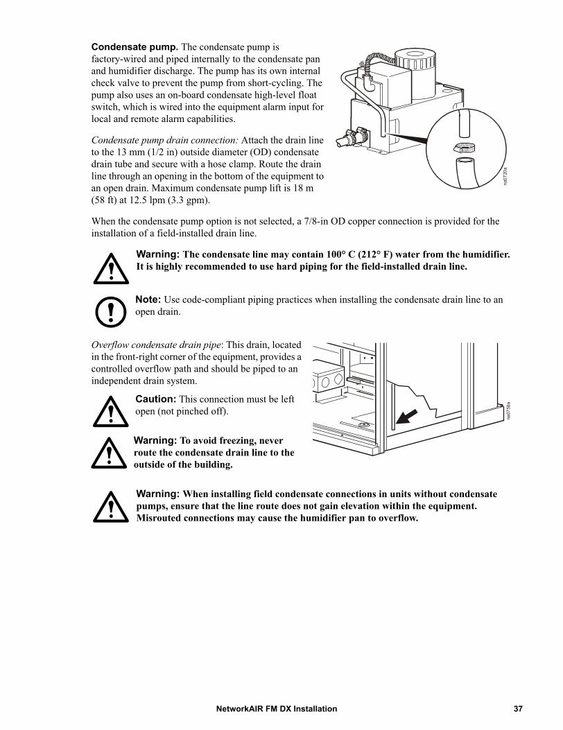
Condensate pump. The condensate pump is factory-wired and piped internally to the condensate pan and humidifier discharge. The pump has its own internal check valve to prevent the pump from short-cycling. The pump also uses an on-board condensate high-level float switch, which is wired into the equipment alarm input for local and remote alarm capabilities.
Condensate pump drain connection: Attach the drain line to the 13 mm (1/2 in) outside diameter (OD) condensate drain tube and secure with a hose clamp. Route the drain line through an opening in the bottom of the equipment to an open drain. Maximum condensate pump lift is 18 m (58 ft) at 12.5 lpm (3.3 gpm).
When the condensate pump option is not selected, a 7/8-in OD copper connection is provided for the installation of a field-installed drain line.
Warning: The condensate line may contain 100° C (212° F) water from the humidifier. It is highly recommended to use hard piping for the field-installed drain line.
Note: Use code-compliant piping practices when installing the condensate drain line to an open drain.
Overflow condensate drain pipe: This drain, located in the front-right corner of the equipment, provides a controlled overflow path and should be piped to an independent drain system.
Warning: When installing field condensate connections in units without condensate pumps, ensure that the line route does not gain elevation within the equipment. Misrouted connections may cause the humidifier pan to overflow.
na0720a
na0758aCaution: This connection must be left
open (not pinched off).
Warning: To avoid freezing, never route the condensate drain line to the outside of the building.
37NetworkAIR FM DX Installation
Piping connections
Air-cooled. When piping air-cooled systems, be sure to use only clean, refrigerant-grade (Type L) pipe, and follow standard procedures for pipe size selection. The maximum allowable length between the evaporator and condenser is 61 equivalent meters (200 equivalent feet). Vertical runs (hot gas) require a trap every 20 ft (6 m) of rise.
Note: When brazing copper field-installed refrigeration lines, use a nitrogen purge to minimize accumulation of scale during the brazing process.
After field piping has been completed, perform a leak test and evacuate the system before final system charging.
1. Using dry refrigerant, pressurize the system to 14 kPa (2 psig).2. Using nitrogen, pressurize the system to 689 kPa (100 psig) and check all pipe joints and fittings.
Repair leaks as required and repeat this process until the system is leak-free.3. Release all of the nitrogen charge from the system and attach a good quality vacuum pump and
micron gauge to the system.4. Evacuate the system to 500 microns, turn off the pump, and allow the system to stand for 2 hours.
Ensure that the system has not risen above 2,000 microns after two hours. Repeat this procedure as necessary.
5. At this point, the system can be fully charged.Water/glycol-cooled. Do not route piping where it will interfere with the air discharge. Install shutoff valves for routine service and emergency isolation of the equipment.
Note: Steel tubes and fittings must not be connected directly to copper tubes or fittings. Use dielectric fittings to prevent corrosion.
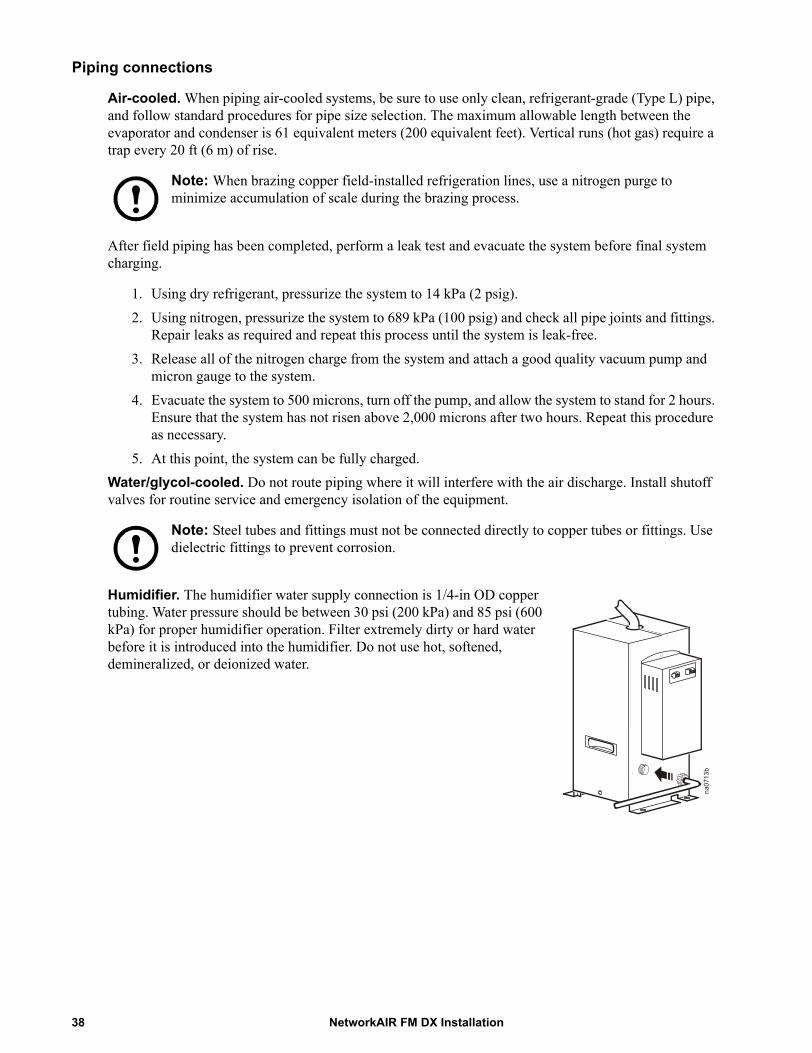
Humidifier. The humidifier water supply connection is 1/4-in OD copper tubing. Water pressure should be between 30 psi (200 kPa) and 85 psi (600 kPa) for proper humidifier operation. Filter extremely dirty or hard water before it is introduced into the humidifier. Do not use hot, softened, demineralized, or deionized water.
na0713b
NetworkAIR FM DX Installation38

Pressure relief valve. All water- and glycol-cooled equipment is supplied with pressure relief valves on the receiver. Pipe these valves to a safe outdoor location, particularly if the data center is equipped with a Halon fire-suppression system. When the flooded receiver option is not used, field-install the pressure relief valve supplied with the air-cooled condenser at the condenser refrigerant inlet connection. If the flooded receiver option will be installed, you do not need to install the relief valve.
Note: When installing the pressure relief valve on the outside condenser piping, use a brass female adapter to avoid leaks. Observe all local and national codes.
Note: Use only type L tubing for refrigeration and air conditioning lines. Do not use soft solder when brazing type L tubing.
1. Install the factory-supplied pressure relief valve on the refrigerant discharge line (air-cooled systems only).
2. Install a brass female adapter to avoid leaks, and secure to the pressure relief valve and the copper tee fitting using silver solder.
3. Wrap the pressure relief valve while soldering to avoid damaging the valve.
Item Description
Copper tee fitting
Brass bushing
Pressure relief valve
Charging/service valve (field-installed)
Discharge line
OHE
na2428a
39NetworkAIR FM DX Installation

Electrical ConnectionsThe following electrical connections are required in the field:
• Controls• Flooded reciever heater• Outdoor Heat Exchanger (OHE)• PCIOM• Communication• Main power
See the electrical schematics supplied with the equipment for all electrical connections.
All electrical connections must be in accordance with national and local codes. See the nameplate for voltage and current requirements. A power disconnect is required to isolate each FM precision air conditioner for maintenance and service.
All low-voltage connections, including data and control connections, must be made with properly insulated wires. The low-voltage connections must have 300 V minimum insulation for 208/230 V equipment, and 600 V insulation for 460/480 V equipment.
All refrigeration control wiring must be installed in accordance with all applicable local and national codes.
Electrical Hazard: Potentially dangerous and lethal voltages exist within this equipment. More than one disconnect switch may be required to energize or de-energize this equipment. Observe all cautions and warnings. Failure to do so could result in serious injury or death. Only qualified service and maintenance personnel should attempt to work on this equipment.
Warning: Lockout/Tagout is a safety procedure that removes access to a device and physically labels the device as intentionally out of service.
Lockout/Tagout power, then use a voltmeter to ensure that power is off before making any electrical connections.
Control connections
Depending on the configuration, additional control connections may be required for the CAN bus, redundant equipment wiring, remote communications through APC Network Management Card support, or traditional equipment-monitoring software.
Control connections:
• Outdoor Heat Exchanger (OHE)• Input/output Modules
NetworkAIR FM DX Installation40

OHE connections
See “User interface box” on page 11.
OHE run signalconnections
To another module when using acommon OHE for multiple modules
41NetworkAIR FM DX Installation

Input and output connections—PCIOM
NetworkAIR FM DX Installation42
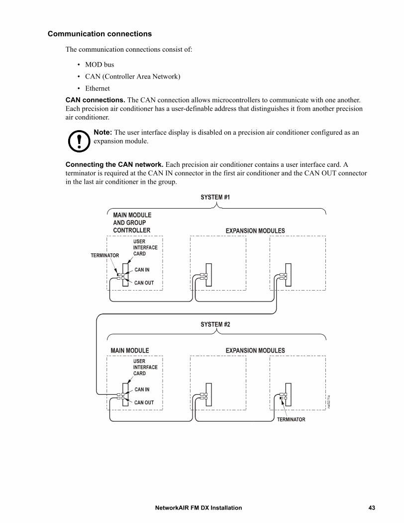
Communication connections
The communication connections consist of:
• MOD bus• CAN (Controller Area Network)• Ethernet
CAN connections. The CAN connection allows microcontrollers to communicate with one another. Each precision air conditioner has a user-definable address that distinguishes it from another precision air conditioner.
Note: The user interface display is disabled on a precision air conditioner configured as an expansion module.
Connecting the CAN network. Each precision air conditioner contains a user interface card. A terminator is required at the CAN IN connector in the first air conditioner and the CAN OUT connector in the last air conditioner in the group.
43NetworkAIR FM DX Installation
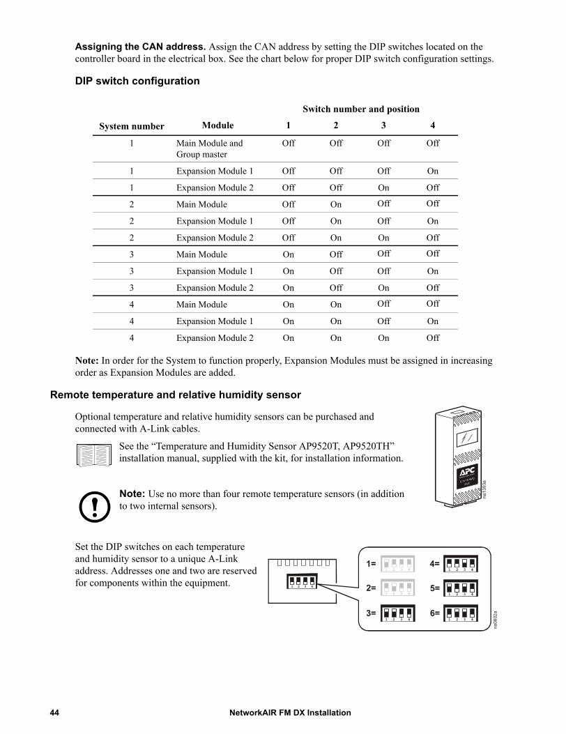
Assigning the CAN address. Assign the CAN address by setting the DIP switches located on the controller board in the electrical box. See the chart below for proper DIP switch configuration settings.
DIP switch configuration
Note: In order for the System to function properly, Expansion Modules must be assigned in increasing order as Expansion Modules are added.
Remote temperature and relative humidity sensor
Optional temperature and relative humidity sensors can be purchased and connected with A-Link cables.
Set the DIP switches on each temperature and humidity sensor to a unique A-Link address. Addresses one and two are reserved for components within the equipment.
Switch number and position
System number Module 1 2 3 4
1 Main Module and Group master
Off Off Off Off
1 Expansion Module 1 Off Off Off On
1 Expansion Module 2 Off Off On Off
2 Main Module Off On Off Off
2 Expansion Module 1 Off On Off On
2 Expansion Module 2 Off On On Off
3 Main Module On Off Off Off
3 Expansion Module 1 On Off Off On
3 Expansion Module 2 On Off On Off
4 Main Module On On Off Off
4 Expansion Module 1 On On Off On
4 Expansion Module 2 On On On Off
See the “Temperature and Humidity Sensor AP9520T, AP9520TH” installation manual, supplied with the kit, for installation information.
Note: Use no more than four remote temperature sensors (in addition to two internal sensors).
1 2 3 4
1 2 3 41=
2=
1 2 3 43=
1 2 3 44=
1 2 3 45=
1 2 3 46=
1 2 3 4
na0802a
NetworkAIR FM DX Installation44
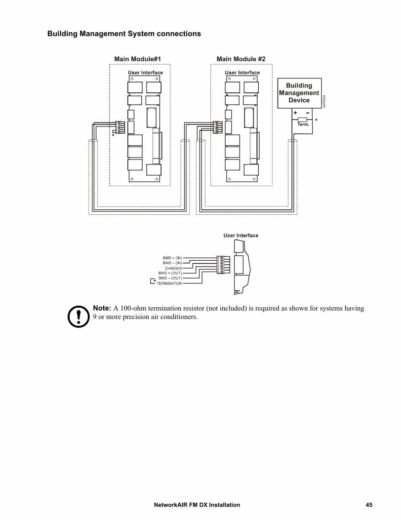
Building Management System connections
Note: A 100-ohm termination resistor (not included) is required as shown for systems having 9 or more precision air conditioners.
45NetworkAIR FM DX Installation

Glycol system electrical connections
PCIOM
USER INTERFACE
FM UNIT – USER INTERFACE BOX
PUMP PACKAGE PANEL
FLUID-COOLER CONTROL PANEL
TB2TB3 TB4
TB
OHE
INPUT #1
FLUID FLOW SWITCH
PUMP
#1 2
4VAC
PUMP
#2 2
4VAC
PUMP
COM
MON
OHE
RESE
T CO
MMON
PUM
P CY
CLE
JUM
PER
DUAL
PUM
P JU
MPER
ECON
MOD
E JU
MPER
GROUND
OHE
COMM
ON
RESE
T
na03
98a
REMO
TE P
UMP
ALAR
M RE
MOTE
PUM
P AL
ARM
COM.
FLUI
D FL
OW S
WIT
CH
NetworkAIR FM DX Installation46
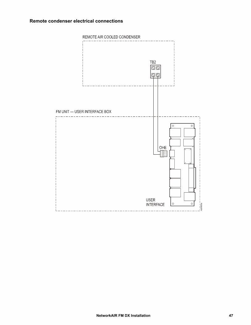
Remote condenser electrical connections
47NetworkAIR FM DX Installation
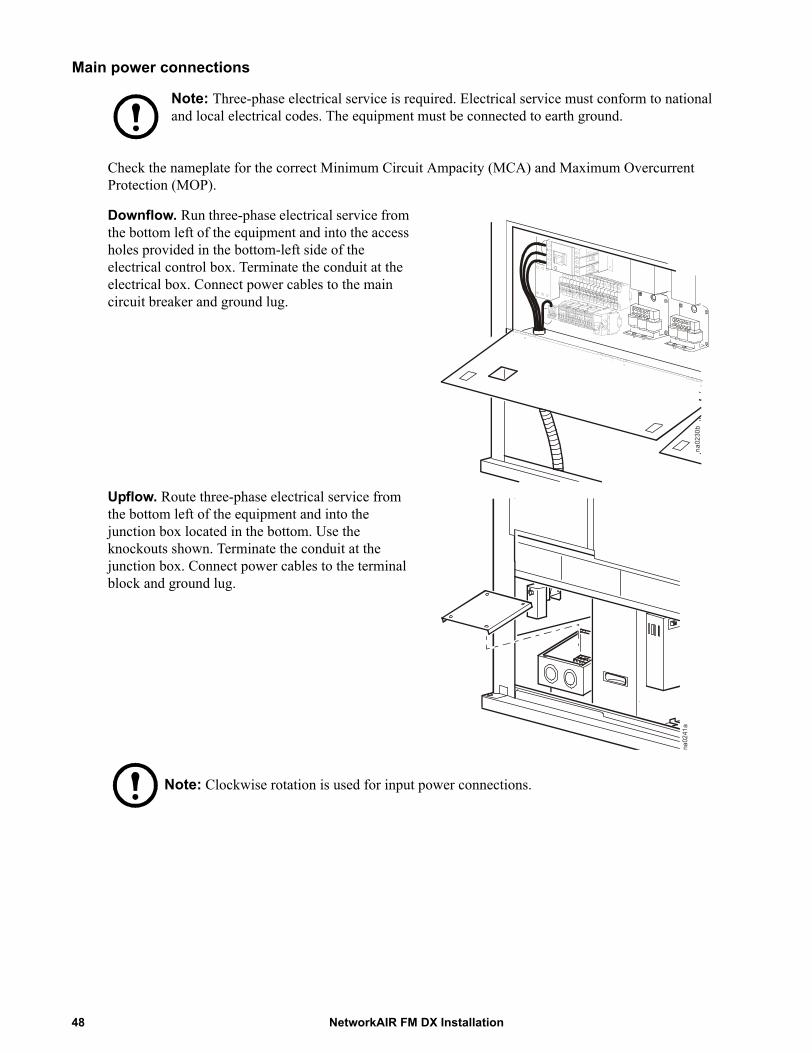
Main power connections
Note: Three-phase electrical service is required. Electrical service must conform to national and local electrical codes. The equipment must be connected to earth ground.
Check the nameplate for the correct Minimum Circuit Ampacity (MCA) and Maximum Overcurrent Protection (MOP).
Downflow. Run three-phase electrical service from the bottom left of the equipment and into the access holes provided in the bottom-left side of the electrical control box. Terminate the conduit at the electrical box. Connect power cables to the main circuit breaker and ground lug.
Upflow. Route three-phase electrical service from the bottom left of the equipment and into the junction box located in the bottom. Use the knockouts shown. Terminate the conduit at the junction box. Connect power cables to the terminal block and ground lug.
Note: Clockwise rotation is used for input power connections.
na0230b
na0241a
NetworkAIR FM DX Installation48
Warranty
One-Year Factory WarrantyThe limited warranty provided by American Power Conversion (APC®) in this Statement of Limited Factory Warranty applies only to products you purchase for your commercial or industrial use in the ordinary course of your business.
Terms of warranty
American Power Conversion warrants its products to be free from defects in materials and workmanship for a period of one year from the date of purchase. The obligation of APC under this warranty is limited to repairing or replacing, at its sole discretion, any such defective products. This warranty does not apply to equipment that has been damaged by accident, negligence or misapplication or has been altered or modified in any way. Repair or replacement of a defective product or part thereof does not extend the original warranty period. Any parts furnished under this warranty may be new or factory-remanufactured.
Non-transferable warranty
This warranty extends only to the original purchaser who must have properly registered the product. The product may be registered at the APC Web site, www.apc.com.
Exclusions
APC shall not be liable under the warranty if its testing and examination disclose that the alleged defect in the product does not exist or was caused by end user’s or any third person’s misuse, negligence, improper installation or testing. Further, APC shall not be liable under the warranty for unauthorized attempts to repair or modify wrong or inadequate electrical voltage or connection, inappropriate on-site operation conditions, corrosive atmosphere, repair, installation, start-up by non-APC designated personnel, a change in location or operating use, exposure to the elements, Acts of God, fire, theft, or installation contrary to APC recommendations or specifications or in any event if the APC serial number has been altered, defaced, or removed, or any other cause beyond the range of the intended use.
THERE ARE NO WARRANTIES, EXPRESS OR IMPLIED, BY OPERATION OF LAW OR OTHERWISE, OF PRODUCTS SOLD, SERVICED OR FURNISHED UNDER THIS AGREEMENT OR IN CONNECTION HEREWITH. APC DISCLAIMS ALL IMPLIED WARRANTIES OF MERCHANTABILITY, SATISFACTION AND FITNESS FOR A PARTICULAR PURPOSE. APC EXPRESS WARRANTIES WILL NOT BE ENLARGED, DIMINISHED, OR AFFECTED BY AND NO OBLIGATION OR LIABILITY WILL ARISE OUT OF, APC RENDERING OF TECHNICAL OR OTHER ADVICE OR SERVICE IN CONNECTION WITH THE PRODUCTS. THE FOREGOING WARRANTIES AND REMEDIES ARE EXCLUSIVE AND IN LIEU OF ALL OTHER WARRANTIES AND REMEDIES. THE WARRANTIES SET FORTH ABOVE CONSTITUTE APC’S SOLE LIABILITY AND PURCHASER’S EXCLUSIVE REMEDY FOR ANY BREACH OF SUCH WARRANTIES. APC WARRANTIES EXTEND ONLY TO PURCHASER AND ARE NOT EXTENDED TO ANY THIRD PARTIES.
49NetworkAIR FM DX Installation
IN NO EVENT SHALL APC, ITS OFFICERS, DIRECTORS, AFFILIATES OR EMPLOYEES BE LIABLE FOR ANY FORM OF INDIRECT, SPECIAL, CONSEQUENTIAL OR PUNITIVE DAMAGES, ARISING OUT OF THE USE, SERVICE OR INSTALLATION, OF THE PRODUCTS, WHETHER SUCH DAMAGES ARISE IN CONTRACT OR TORT, IRRESPECTIVE OF FAULT, NEGLIGENCE OR STRICT LIABILITY OR WHETHER APC HAS BEEN ADVISED IN ADVANCE OF THE POSSIBILITY OF SUCH DAMAGES. SPECIFICALLY, APC IS NOT LIABLE FOR ANY COSTS, SUCH AS LOST PROFITS OR REVENUE, LOSS OF EQUIPMENT, LOSS OF USE OF EQUIPMENT, LOSS OF SOFTWARE, LOSS OF DATA, COSTS OF SUBSTITUENTS, CLAIMS BY THIRD PARTIES, OR OTHERWISE.
NO SALESMAN, EMPLOYEE OR AGENT OF APC IS AUTHORIZED TO ADD TO OR VARY THE TERMS OF THIS WARRANTY. WARRANTY TERMS MAY BE MODIFIED, IF AT ALL, ONLY IN WRITING SIGNED BY AN APC OFFICER AND LEGAL DEPARTMENT.
Warranty claims
Customers with warranty claims issues may access the APC customer support network through the Support page of the APC Web site, www.apc.com/support. Select your country from the country selection pull-down menu at the top of the Web page. Select the Support tab to obtain contact information for customer support in your region.
NetworkAIR FM DX Installation50
Warranty Procedures
Claims
To obtain service under the warranty, contact APC Customer Support (see the back cover of this manual for contact information). You will need the model number of the Product, the serial number, and the date purchased. A technician will also ask you to describe the problem. If it is determined that the Product will need to be returned to APC, you must obtain a returned material authorization (RMA) number from APC Customer Support. Products that must be returned must have the RMA number marked on the outside of the package and must be returned with transportation charges prepaid. If it is determined by APC Customer Support that on-site repair of the Product is allowed, APC will arrange to have APC authorized service personnel dispatched to the Product location for repair or replacement, at the discretion of APC.
Parts
• APC warrants the parts of their systems for 1 year from the date of commissioning or 18 months from the ship date. This warranty only covers the cost of the part and not the labor for installation.
• Calls for warranty parts requests need to have specific unit information (serial number, model number, job number) to allow proper identification and processing of the warranty part transaction.
• A purchase order may be required to issue any warranty parts. An invoice will be sent once the parts are shipped to the field. You have 30 days to return the defective parts to APC. After 30 days, the warranty invoice will be outstanding, and payment of the invoice will be expected in full.
• Return authorization documentation will be sent with the replacement part. This documentation must be sent back with the defective part to APC for proper identification of the warranty return. Mark the warranty return number on the outside of the package.
• After the part has been received at APC, we will determine the status of the credit based on the findings of the returned part. Parts that are damaged from lack of maintenance, misapplication, improper installation, shipping damage, or acts of man/nature will not be covered under the parts warranty.
• Any warranty parts request received before 1:00 PM EST will be shipped same-day standard ground delivery. Any costs associated with Next Day or Airfreight will be the responsibility of the party requesting the part.
• Return freight of warranty parts to APC is the responsibility of the party returning the part.
51NetworkAIR FM DX Installation


06/2007990-3120*990-3120*
APC Worldwide Customer SupportCustomer support for this or any other APC product is available at no charge in any of the following ways:
• Visit the APC Web site to access documents in the APC Knowledge Base and to submit customer support requests.– www.apc.com (Corporate Headquarters)
Connect to localized APC Web sites for specific countries, each of which provides customer support information.
– www.apc.com/support/Global support searching APC Knowledge Base and using e-support.
• Contact an APC Customer Support center by telephone or e-mail.– Regional centers
– Local, country-specific centers: go to www.apc.com/support/contact for contact information.
Contact the APC representative or other distributor from whom you purchased your APC product for information on how to obtain local customer support.
Direct InfraStruXure Customer Support Line
(1)(877)537-0607 (toll free)
APC headquarters U.S., Canada
(1)(800)800-4272 (toll free)
Latin America (1)(401)789-5735 (USA)
Europe, Middle East, Africa
(353)(91)702000 (Ireland)
Western Europe (inc. Scandinavia) +800 0272 0272
Japan (0) 36402-2001
Australia, New Zealand, South Pacific area
(61) (2) 9955 9366 (Australia)
Entire contents copyright 2007 American Power Conversion Corporation. All rights reserved. Reproduction in whole or in part without permission is prohibited. APC, the APC logo, InfraStruXure, and NetworkAIR
are trademarks of American Power Conversion Corporation. All other trademarks, product names, and corporate names are the property of their respective owners and are used for informational purposes only.


![Zgbc F B Dmavfbg ©BBBªBBBBBBBBBBBBBBBBBB ]karatevolkhov.ru/Pervenstvo_MLBI_2018.pdf · ^h dx klZjr_ dx dx klZjr_ dx 8 - e_l FZevqbdb ^h dx\dexqbl_evgh ^h dx\dexqbl_evgh >_\hqdb](https://static.fdocuments.us/doc/165x107/5ec420b3644640007216892f/zgbc-f-b-dmavfbg-bbbbbbbbbbbbbbbbbbbbb-h-dx-klzjr-dx-dx-klzjr-dx-8-el.jpg)