Network -to -Network FR/ATM SVC Service Interworking
65
Network-to-Network FR/ATM SVC Service Interworking Implementation Agreement FRF. 18 Frame Relay Forum Technical Committee April 2000
Transcript of Network -to -Network FR/ATM SVC Service Interworking

Network-to-Network FR/ATM SVC Service Interworking Implementation
Agreement
FRF. 18
Frame Relay Forum Technical Committee April 2000

ii
Note: The user’s attention is called to the possibility that implementation of the frame relay implementation agreement contained herein may require the use of inventions covered by patent rights held by third parties. By publication of this frame relay implementation of the specification will not infringe on any third party rights. The Frame Relay Forum takes no position with respect to any claim that has been or may be asserted by any third party, the validity of any patent rights related to such claims, or the extent to which a license to use such rights may or may not be available.
For additional information contact:
The Frame Relay Forum
Worldwide Headquarters
39355 California St., Suite 307
Fremont, CA 94538
Phone: + 1 510.608.5920
FAX: +1 510.608.5917
E-mail:[email protected]
Full Notice
Copyright © (2000) The Frame Relay Forum.
All rights reserved.
This document and translations of it may be copied and furnished to others, and works that comment on or otherwise explain it or assist in its implementation may be prepared, copied, published and distributed, in whole or in part, without restriction of any kind, provided that the above copyright notice and this paragraph are included on all such copies and derivative works. However, this document itself may not be modified in any way, such as by removing the copyright notice or references to the Frame Relay Forum, except as needed for the purpose of developing Frame Relay standards (in which case the procedures for copyrights defined by the Frame Relay Forum must be followed), or as required to translate it into languages other than English
This document and the information contained herein is provided on an "AS IS" basis and THE FRAME RELAY FORUM DISCLAIMS ALL WARRANTIES, EXPRESS OR IMPLIED, INCLUDING BUT NOT LIMITED TO ANY WARRANTY THAT THE USE OF THE INFORMATION HEREIN WILL NOT INFRINGE ANY RIGHTS OR ANY IMPLIED WARRANTIES OF MERCHANTABILITY OR FITNESS FOR A PARTICULAR PURPOSE.

iii
Editor: Bill Coutts Lucent Technologies

iv
1.0 INTRODUCTION ...............................................................................................................1
1.1 PURPOSE................................................................................................................................1 1.2 SCOPE AND OVERVIEW ..........................................................................................................1 1.3 DEFINITIONS ..........................................................................................................................1 1.4 ACRONYMS............................................................................................................................2
2.0 REFERENCES....................................................................................................................3
3.0 FRAME RELAY/ATM PVC SERVICE INTERWORKING............................................5
3.1 ATM OPERATIONS, ADMINISTRATION, AND MAINTENANCE (OA&M) INTERWORKING ..........5
4.0 FRAME RELAY/ATM SVC SERVICE INTERWORKING............................................5
4.1 DLCI AND VPI/VCI FIELDS...................................................................................................7 4.2 ADDRESSES ...........................................................................................................................8
4.2.1 Calling/Called/Connected Party Addresses .....................................................................8 4.2.1.1 Direct Translations ................................................................................................................................9 4.2.1.2 FR Native E.164 / ATM AESA E.164 (zero-valued DSP) Translation ....................................................9 4.2.1.3 FR Native X.121 / ATM AESA X.121 (zero-valued DSP) Translation....................................................9
4.2.2 Calling/Called/Connected Party Subaddresses..............................................................10 4.2.2.1 FR NSAP / ATM NSAP Translation ....................................................................................................11 4.2.2.1 FR User-Specified / ATM User-Specified Translation..........................................................................11 4.2.2.2 ATM AESA.........................................................................................................................................11
4.3 TRAFFIC PARAMETER NEGOTIATION AND TRANSLATION......................................................11 4.4 FRAME RELAY SWITCHED PVCS AND ATM SOFT PVCS......................................................12
4.4.1 FRF.10.1 -to- PNNI 1.0 Translation Requirements........................................................14 4.5 PNNI ROUTING ...................................................................................................................15 4.6 CAUSE VALUES....................................................................................................................16 4.7 CALL STATES AND TIMERS ..................................................................................................16 4.8 MULTIPROTOCOL ENCAPSULATION INTERWORKING .............................................................16
5.0 FRAME RELAY/ATM SVC SIGNALING MESSAGE TRANSLATION.....................21
5.1 FRAME RELAY INITIATED CALL ESTABLISHMENT.................................................................23 5.1.1 Setup Message Translation (Frame Relay -> ATM at IWF)...........................................24
5.1.1.1 ATM Connection Identifier IE..............................................................................................................25 5.1.1.2 ATM Broadband Bearer Capability IE .................................................................................................25 5.1.1.3 ATM Designated Transit List IE ..........................................................................................................26 5.1.1.4 ATM Quality of Service Parameter IE..................................................................................................26 5.1.1.5 ATM AAL Parameters IE.....................................................................................................................26 5.1.1.6 ATM Traffic Descriptor IE...................................................................................................................26 5.1.1.7 ATM Minimum Acceptable Traffic Descriptor IE ................................................................................27 5.1.1.8 ATM Broadband Repeat Indicator IE and Broadband Low Layer Information IE...................................27 5.1.1.9 ATM Calling Party Number IE ............................................................................................................27 5.1.1.10 ATM Calling Party Subaddress IE......................................................................................................27 5.1.1.11 ATM Called Party Number IE............................................................................................................27 5.1.1.12 ATM Called Party Subaddress IE.......................................................................................................28 5.1.1.13 ATM Calling Party SPVCC IE ...........................................................................................................28 5.1.1.14 ATM Called Party SPVCC IE ............................................................................................................28 5.1.1.15 ATM Transit Network Selection IE....................................................................................................28
5.1.2 Call Proceeding Message Handling (Frame Relay <- ATM at IWF)..............................28 5.1.2.1 Frame Relay Data Link Connection Identifier IE ..................................................................................30
5.1.3 Alerting Message Handling (Frame Relay <- ATM at IWF) ..........................................30

v
5.1.4 Progress Message Handling (Frame Relay <- ATM at IWF) .........................................30 5.1.5 Notify Message Handling (Frame Relay <- ATM at IWF) .............................................30 5.1.6 Connect Message Translation (Frame Relay <- ATM at IWF).......................................31
5.1.6.1 Frame Relay Connected Number IE .....................................................................................................32 5.1.6.2 Frame Relay Connected Subaddress IE ................................................................................................32 5.1.6.3 Frame Relay Link Layer Core Parameters IE........................................................................................32 5.1.6.4 Frame Relay Called Party SPVC IE......................................................................................................33 5.1.6.5 Frame Relay Low Layer Compatibility IE.............................................................................................33
5.2 FRAME RELAY INITIATED CALL CLEARING...........................................................................34 5.3 ATM INITIATED CALL ESTABLISHMENT...............................................................................36
5.3.1 Setup Message Translation (Frame Relay <- ATM at IWF)...........................................37 5.3.1.1 Frame Relay Data Link Connection Identifier IE ..................................................................................38 5.3.1.2 Frame Relay Bearer Capability IE........................................................................................................38 5.3.1.3 Frame Relay Link Layer Core Parameters ............................................................................................38 5.3.1.4 Frame Relay Low Layer Compatibility IE.............................................................................................39 5.3.1.5 Frame Relay Calling Party Number IE .................................................................................................39 5.3.1.6 Frame Relay Calling Party Subaddress IE ............................................................................................39 5.3.1.7 Frame Relay Called Party Number IE...................................................................................................39 5.3.1.8 Frame Relay Called Party Subaddress IE..............................................................................................40 5.3.1.9 Frame Relay Calling Party SPVC IE ....................................................................................................40 5.3.1.10 Frame Relay Called Party SPVC IE....................................................................................................40 5.3.1.11 Frame Relay Transit Network Selection IE.........................................................................................40 5.3.1.12 Frame Relay Call Identification IE .....................................................................................................40 5.3.1.13 Frame Relay Priority and Service Class Parameters IE .......................................................................40
5.3.2 Call Proceeding Message Handling (Frame Relay -> ATM at IWF)..............................41 5.3.2.1 ATM Connection Identifier IE..............................................................................................................41
5.3.3 Connect Message Translation (Frame Relay -> ATM at IWF).......................................42 5.3.3.1 ATM Connected Number IE ................................................................................................................42 5.3.3.2 ATM Connected Subaddress IE ...........................................................................................................42 5.3.3.3 ATM Traffic Descriptor IE...................................................................................................................43 5.3.3.4 ATM AAL Parameters .........................................................................................................................43 5.3.3.5 ATM Called Party SPVCC IE ..............................................................................................................43 5.3.3.6 ATM Broadband Low Layer Information IE .........................................................................................43
5.4 ATM INITIATED CALL CLEARING.........................................................................................44
ANNEX A - CONVERSION OF TRAFFIC PARAMETERS ...............................................46
A.1 CONVERSION FROM FRAME RELAY TO ATM TRAFFIC PARAMETERS...................................46 A.2 CONVERSION FROM ATM TO FR TRAFFIC PARAMETERS.....................................................47
ANNEX B - GENERIC APPLICATION TRANSPORT (GAT) ...........................................49
B.1 GENERAL DESCRIPTION......................................................................................................49 B.2 ADDITIONS TO FR/ATM SVC SIGNALLING TRANSLATIONS ................................................50 B.2.1 FR TO ATM TRANSLATION .............................................................................................50
B.2.1.1 Tunnelling of FRF.10.1 Information Elements ..........................................................50 B.2.1.1.1 FR Information Elements With No ATM Equivalent........................................................................50 B.2.1.1.2 FR Information Elements Without Direct Mapping..........................................................................53
B.2.1.2 Translation of FRF.10.1 GAT IE With Organization Specific Information ................53 B.2.2 ATM TO FR TRANSLATION REQUIREMENTS....................................................................55
B.2.2.1 Translation of PNNI GAT IE with FRF.10.1 Information Elements ...........................55 B.2.2.2 Translation of PNNI GAT IE with Organization-Specific Information.......................56
ANNEX C – ATM FORUM PNNI SPVC ADDENDUM REQUIREMENTS.......................58
C.1 GENERAL DESCRIPTION......................................................................................................58 C.2 ADDITIONS TO FR/ATM SVC SIGNALLING TRANSLATIONS.................................................58

vi
C.2.1 FR to ATM Translation Requirements ........................................................................58 C.2.1.1 Called Party SPVC IE Translation......................................................................................................58 C.2.1.2 Calling Party SPVC IE Translation.....................................................................................................59
C.2.2 ATM to FR Translation ................................................................................................59 C.2.2.1 Called Party SPVC IE Translation.......................................................................................................59 C.2.2.2 Calling Party SPVC IE Translation.....................................................................................................59
Revision History
Version Date Changes
FRF NNSVCFRA
TMIW
April 2000
1
1.0 Introduction
1.1 Purpose This document is an implementation agreement on Switched Virtual Connection (SVC) service interworking between Frame Relay and Asynchronous Transfer Mode (ATM) technologies at the Network-to-Network Interface (NNI). The agreements herein were reached by the Frame Relay Forum and are based on the documents referenced in section 2.0.
Except as noted, these agreements will form the basis of conformance test suites produced by the Frame Relay Forum.
This document may be submitted to other bodies involved in ratification of implementation agreements and conformance testing to facilitate multi-vendor interoperability.
1.2 Scope and Overview Service interworking applies when a Frame Relay service user interworks with an ATM service user, and the ATM service user performs no Frame Relay specific functions, and the Frame Relay service user performs no ATM specific functions. All interworking is performed by the interworking function (IWF).
Frame Relay/ATM service interworking over PVCs at the user-to-network interface (UNI) and at the NNI is documented in FRF.8[3]. This implementation agreement extends the functionality in FRF.8 to provide for Frame Relay/ATM SVC interworking at the NNI.
The key issues addressed by this contribution include the translation of Frame Relay SVC NNI signaling to ATM SVC NNI signaling. Frame Relay SVC NNI signaling is based on FRF.10.1 [1]. ATM SVC NNI signaling is based on the Private Network-Network Interface Specification (PNNI 1.0 [2]) and its errata (PNNI V1.0 Errata and PICS [14]).
It is intended that, as additional feature annexes are added to PNNI 1.0 by the ATM Forum, this implementation agreement will be updated with annexes as well (provided the features are accepted for FR/ATM interworking by the Frame Relay Forum).
1.3 Definitions Must, Shall, Mandatory, or Required the item is an absolute requirement of the
implementation agreement.
Should the item is highly desirable.
May or Optional the item is not compulsory, and may be followed or ignored according to the needs of the implementer.
Not Applicable the item is outside the scope of this implementation agreement.
Network-to-Network Interface (NNI) the NNI is concerned with the transfer of C-Plane and U-Plane information between two network nodes belonging to two different Frame Relay or ATM networks.

2
Local Significance call control message is relevant only at the local NNI.
Global Significance call control message is relevant at the local NNI, other NNIs, and UNIs related to the call.
1.4 Acronyms AAL ATM Adaptation Layer ABR Available Bit Rate AESA ATM Endsystem Address AR Access Rate ATM Asynchronous Transfer Mode Bc Committed Burst BCD Binary Coded Decimal BCOB Broadband Connection-Oriented Bearer Be Excess Burst B-CPE Broadband Customer Premises Equipment B-ICI Broadband Inter Carrier Interface CBR Constant Bit Rate CIC Carrier Identification Code CIR Committed Information Rate CLP Cell Loss Priority CPE Customer Premises Equipment CPCS Common Part Convergence Sublayer C-Plane Control Plane DCC Data Country Code DLCI Data Link Connection Identifier DE Discard Eligibility DNIC Data Network Identification Code DSP Domain Specific Part DTL Designated Transit List EFCI Explicit Forward Congestion Indicator EIR Excess Information Rate FECN Forward Explicit Congestion Notification FMIF Frame Mode Information Field FR Frame Relay FRF Frame Relay Forum FRFTC Frame Relay Forum Technical Committee FR-CPE Frame Relay Customer Premises Equipment GAT Generic Application Transport ICD International Code Designator IDP Initial Domain Part IE Information Element ITU International Telecommunication Union IWF Interworking Function MBS Maximum Burst Size NNI Network to Network Interface NSAP Network Service Access Point OA&M Operations, Administration, and Maintenance
3
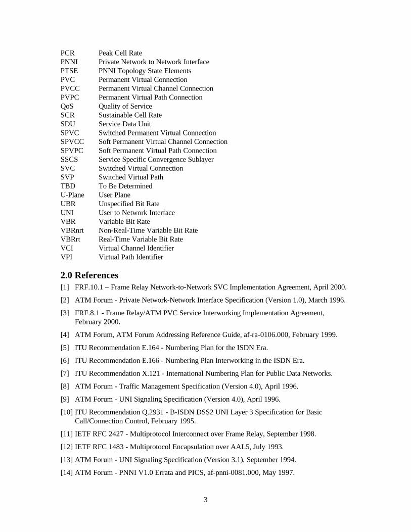
PCR Peak Cell Rate PNNI Private Network to Network Interface PTSE PNNI Topology State Elements PVC Permanent Virtual Connection PVCC Permanent Virtual Channel Connection PVPC Permanent Virtual Path Connection QoS Quality of Service SCR Sustainable Cell Rate SDU Service Data Unit SPVC Switched Permanent Virtual Connection SPVCC Soft Permanent Virtual Channel Connection SPVPC Soft Permanent Virtual Path Connection SSCS Service Specific Convergence Sublayer SVC Switched Virtual Connection SVP Switched Virtual Path TBD To Be Determined U-Plane User Plane UBR Unspecified Bit Rate UNI User to Network Interface VBR Variable Bit Rate VBRnrt Non-Real-Time Variable Bit Rate VBRrt Real-Time Variable Bit Rate VCI Virtual Channel Identifier VPI Virtual Path Identifier
2.0 References [1] FRF.10.1 – Frame Relay Network-to-Network SVC Implementation Agreement, April 2000.
[2] ATM Forum - Private Network-Network Interface Specification (Version 1.0), March 1996.
[3] FRF.8.1 - Frame Relay/ATM PVC Service Interworking Implementation Agreement, February 2000.
[4] ATM Forum, ATM Forum Addressing Reference Guide, af-ra-0106.000, February 1999.
[5] ITU Recommendation E.164 - Numbering Plan for the ISDN Era.
[6] ITU Recommendation E.166 - Numbering Plan Interworking in the ISDN Era.
[7] ITU Recommendation X.121 - International Numbering Plan for Public Data Networks.
[8] ATM Forum - Traffic Management Specification (Version 4.0), April 1996.
[9] ATM Forum - UNI Signaling Specification (Version 4.0), April 1996.
[10] ITU Recommendation Q.2931 - B-ISDN DSS2 UNI Layer 3 Specification for Basic Call/Connection Control, February 1995.
[11] IETF RFC 2427 - Multiprotocol Interconnect over Frame Relay, September 1998.
[12] IETF RFC 1483 - Multiprotocol Encapsulation over AAL5, July 1993.
[13] ATM Forum - UNI Signaling Specification (Version 3.1), September 1994.
[14] ATM Forum - PNNI V1.0 Errata and PICS, af-pnni-0081.000, May 1997.

4
[15] ITU Recommendation Q.850 – Usage of Cause and Location in the DSS1 and the SS7 ISDN User Part, March 1993.
[16] ITU Recommendation Q.2610 – B-ISDN Usage of Cause and Location in B-ISDN User Part and DSS2, February 1995.
[17] ATM Forum, PNNI Generic Application Transport Addendum Straw Ballot Text, str-cs-pnni-gat-01.01, February 1999.
[18] ITU-T, Digital Subscriber Signalling System No. 2 (DSS2) - Signalling specification for Frame Relay service, ITU-T Recommendation Q.2933 (07/96).
[19] ATM Forum, PNNI SPVC Addendum (Version 1.0 Final Ballot), af-cs-0127.000, April 1999.

5
3.0 Frame Relay/ATM PVC Service Interworking Sections of the Frame Relay/ATM PVC Service Interworking Implementation Agreement (FRF.8.1) shall also apply to this implementation agreement. These sections address Frame Relay frame -to - ATM cell parameter mapping, traffic management, link integrity, protocol encapsulation, and address resolution. The applicable sections are the following:
4.0 Frame Relay/ATM Service Interworking Parameters Mapping (and its subsections)
5.1 Traffic Management 5.2.1.1 Link Integrity Verification (Paragraph 1 only) 5.3 Upper Layer User Protocol Encapsulation (and its subsections) 5.4 Address Resolution 6.0 Operations for the Common Part of the AAL Type 5
In FRF.8.1 section 4.2, the selection of mode 1 or mode 2 for the discard eligibility (DE) - to - cell loss priority (CLP) mapping shall be as defined in Annex A of this document.
In FRF.8.1 section 4.3, mode 1 mapping of Forward Explicit Congestion Notification (FECN) - to - Explicit Forward Congestion Indicator (EFCI) shall be provided by the IWF. It is an implementation option to provide mode 2 as a configurable selection at the IWF.
In FRF.8.1 section 5.3, transparent (mode 1) and translation (mode 2) modes are defined for processing the encapsulation of upper layer protocol PDUs. If the IWF supports translation mode, detection of the encapsulation method shall be as defined in section 4.8 of this document.
3.1 ATM Operations, Administration, and Maintenance (OA&M) Interworking ATM SVC OA&M signaling has no counterpart on the FR SVC side of the IWF. While OAM alarm surveillance (OA&M F5 AIS and RDI cells) - to - LMI translation is supported for PVCs per FRF.8.1, there is no FR SVC equivalent. In addition, there is no FR equivalent for OA&M connectivity (loopback) verification. Until equivalent FR SVC standards are developed for OA&M signaling, OA&M cells shall be terminated at the IWF: the IWF shall detect AIS cells and generate RDI cells; and the IWF shall either loopback or remove OA&M loopback cells depending on the value in the cell’s loopback indication field.
4.0 Frame Relay/ATM SVC Service Interworking Figure 1 illustrates service interworking between Frame Relay and ATM SVCs at the NNI. As shown, the IWF is best defined using the Frame Relay and ATM SVC protocol stack models. Specifically, the signaling translation performed by the IWF is explained by defining the translations between the FRF.10.1 and the ATM PNNI signaling protocols.
Figure 1 does not imply any particular physical location for an IWF. The IWF may be contained within a single device or within multiple devices. As shown in example A in Figure 1, the IWF may be an entity separate from the Frame Relay and ATM networks. Or, as shown in examples B and C, the IWF may be an integral part of the ATM or Frame Relay network. In the case of example B, it is not necessary for the network to actually generate ATM NNI signaling messages. Likewise in example C, it is not necessary for the network to generate Frame Relay NNI signaling

6
messages. However, in order to unambiguously define the translations, this implementation agreement defines the translations between the FRF.10.1 and the ATM PNNI signaling protocols.
PHY PHY
Q.922
FRF.10.1(X.76)
Signaling Translation
PNNI 1.0
SSCF(Q.2130)
SSCOP(Q.2110)
CP-AAL5
ATM
PHY
UNI 3.x/4.0(Q.2931)
SSCF(Q.2130)
SSCOP(Q.2110)
CP-AAL5
ATM
PHY
Q.922
FRF.4.1(Q.933)
UpperLayers
UpperLayers
FR Network ATM NetworkFR-CPEFR-UNI ATM-UNI
B-CPEATM-NNI
IWF
FR NetworkATM Network
FR-CPEFR-UNI ATM-UNI
B-CPEFR-NNI
IWF
FR Network ATM NetworkFR-CPEFR-UNI ATM-UNI
B-CPEFR-NNI ATM-NNI
IWF
A.
B.
C.
(Q.2931)
Figure 1. Service Interworking Between Frame Relay and ATM SVC Signaling at the NNI
Note that the PNNI recommendation includes more features than the FRF.10.1 implementation agreement. The Frame Relay/ATM IWF is required to support the following PNNI features:
1. Routing procedures (the ATM NNI side of the IWF participates in PNNI routing).
2. Signaling messages and procedures for ATM point-to-point call and connection control.
3. Signaling messages and procedures used with the global call reference.
4. Procedures for non-associated signaling.
5. Signaling of Switched Virtual Channel Connections (SVCCs).
6. Procedures for point-to-point Soft Permanent Virtual Channel Connections (SPVCCs).
7
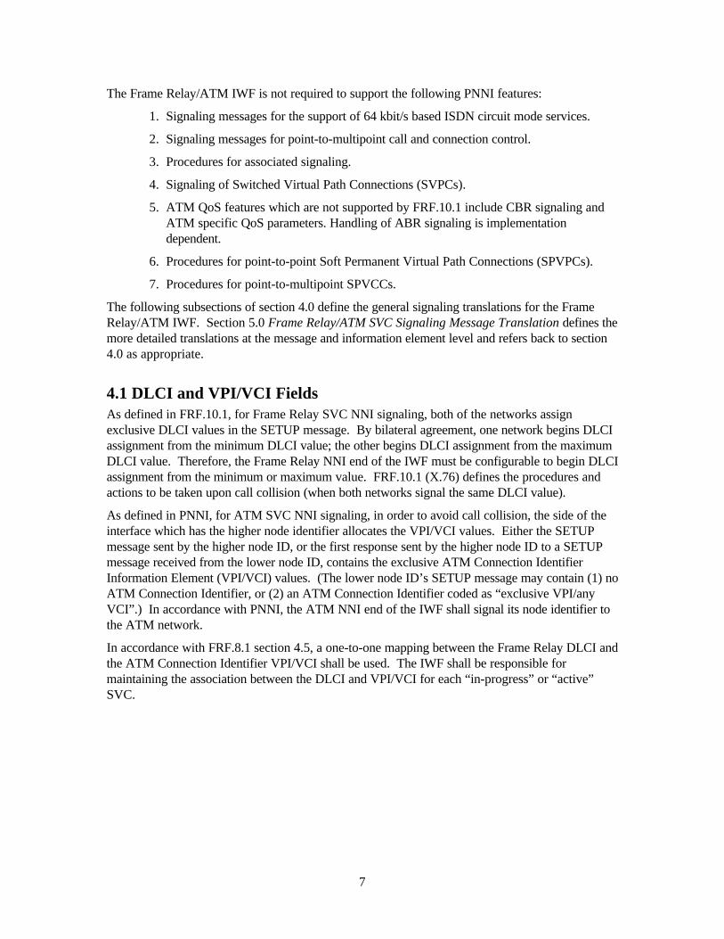
The Frame Relay/ATM IWF is not required to support the following PNNI features:
1. Signaling messages for the support of 64 kbit/s based ISDN circuit mode services.
2. Signaling messages for point-to-multipoint call and connection control.
3. Procedures for associated signaling.
4. Signaling of Switched Virtual Path Connections (SVPCs).
5. ATM QoS features which are not supported by FRF.10.1 include CBR signaling and ATM specific QoS parameters. Handling of ABR signaling is implementation dependent.
6. Procedures for point-to-point Soft Permanent Virtual Path Connections (SPVPCs).
7. Procedures for point-to-multipoint SPVCCs.
The following subsections of section 4.0 define the general signaling translations for the Frame Relay/ATM IWF. Section 5.0 Frame Relay/ATM SVC Signaling Message Translation defines the more detailed translations at the message and information element level and refers back to section 4.0 as appropriate.
4.1 DLCI and VPI/VCI Fields As defined in FRF.10.1, for Frame Relay SVC NNI signaling, both of the networks assign exclusive DLCI values in the SETUP message. By bilateral agreement, one network begins DLCI assignment from the minimum DLCI value; the other begins DLCI assignment from the maximum DLCI value. Therefore, the Frame Relay NNI end of the IWF must be configurable to begin DLCI assignment from the minimum or maximum value. FRF.10.1 (X.76) defines the procedures and actions to be taken upon call collision (when both networks signal the same DLCI value).
As defined in PNNI, for ATM SVC NNI signaling, in order to avoid call collision, the side of the interface which has the higher node identifier allocates the VPI/VCI values. Either the SETUP message sent by the higher node ID, or the first response sent by the higher node ID to a SETUP message received from the lower node ID, contains the exclusive ATM Connection Identifier Information Element (VPI/VCI) values. (The lower node ID’s SETUP message may contain (1) no ATM Connection Identifier, or (2) an ATM Connection Identifier coded as “exclusive VPI/any VCI”.) In accordance with PNNI, the ATM NNI end of the IWF shall signal its node identifier to the ATM network.
In accordance with FRF.8.1 section 4.5, a one-to-one mapping between the Frame Relay DLCI and the ATM Connection Identifier VPI/VCI shall be used. The IWF shall be responsible for maintaining the association between the DLCI and VPI/VCI for each “in-progress” or “active” SVC.

8
4.2 Addresses Translation between the FRF.10.1 and the PNNI addresses, as presented in this section, is organized into two categories: (1) calling/called/connected party address translations and (2) calling/called/connected party subaddress translations.
4.2.1 Calling/Called/Connected Party Addresses Table 1 identifies the number plans supported by FRF.10.1 and PNNI for calling, called, and connected party addresses. This table also indicates which number plans the IWF is required to translate (mandatory), which are optional, and which are outside the scope of this implementation agreement (blank). See specific subsections of section 5.0 for procedures to follow when the IWF receives an address which it is not required to translate.
Regarding number types, FRF.10.1 (X.76) only allows “international” number types for E.164 and X.121 and “alternate” number types for NSAP. The ATM UNI 4.0[9] recommendation section 3.2 limits native E.164 addresses to the “international” number type and ATM Endsystem Addresses (AESAs) to the “unknown” number type. (Note that, although an ATM AESA is required to be coded as an “unknown” number type, section 3.1.1.3 of ATM UNI 4.0[9] indicates
ternational format of these numbers will be used.”) The IWF shall only translate “international” number types for the native E.164 and X.121 number plans. The IWF shall translate “unknown” number types for the ATM AESA number plans to FR NSAP “alternate” number types; and, in the reverse direction, FR NSAP “alternate” number types shall be translated

9
Table 1. Calling/Called/Connected Party Address Translation
ATM Native E.164 ATM AESA DCC ATM AESA ICDATM AESA E.164 (zero-valued DSP)
ATM AESA E.164 (non-zero DSP)
ATM AESA X.121 (zero-valued DSP)
ATM AESA X.121 (non-zero DSP)
FR Native E.164 Optional (Note) Mandatory
FR Native X.121 Optional
FR NSAP DCC Mandatory
FR NSAP ICD Mandatory
FR NSAP E.164 (zero-valued DSP)
Mandatory
FR NSAP E.164 (non-zero DSP)
Mandatory
FR NSAP X.121 (zero-valued DSP)
Mandatory
FR NSAP X.121 (non-zero DSP)
Mandatory
Note: The ATM Forum Addressing Reference Guide does not support signaling of native E.164 addresses in PNNI.
4.2.1.1 Direct Translations The native E.164 number plan is not supported by ATM PNNI 1.0 switches which conform to the ATM Forum Addressing Reference Guide [4]. The IWF may optionally translate the native E.164 number plan in the FR-to-ATM direction but the SVC is not guaranteed to be routed properly over PNNI networks that comply with the ATM Forum Addressing Reference Guide. It is recommended that FR native E.164 addresses be translated to ATM E.164 AESAs as specified in section 4.2.1.2.
The NSAP number plan is supported by FRF.10.1; the AESA number plan is supported by PNNI. The IWF shall support the following translations in both the FR-to-ATM and the ATM-to-FR directions:
• FR NSAP DCC and ATM AESA DCC • FR NSAP ICD and ATM AESA ICD • FR NSAP E.164 and ATM AESA E.164 • FR NSAP X.121 and ATM AESA X.121
4.2.1.2 FR Native E.164 / ATM AESA E.164 (zero-valued DSP) Translation The IWF shall support translation between the E.164 AESA (with a “zero-valued” or “null-valued” Domain Specific Part (DSP)) and the Frame Relay native E.164 address coding. In the FR-to-ATM direction, the native E.164 ASCII format is translated to the AESA Initial Domain Part (IDP) Binary Coded Decimal (BCD) format; and the AESA DSP is set to zeros. In the opposite direction, if the AESA DSP is zeros, the AESA IDP BCD format is translated to the native E.164 address format.
4.2.1.3 FR Native X.121 / ATM AESA X.121 (zero-valued DSP) Translation The IWF may optionally support translation between the X.121 AESA (with a “zero-valued” or “null-valued” DSP) and the Frame Relay native X.121 address coding. In the FR-to-ATM direction, the native X.121 ASCII format is translated to the AESA IDP BCD format; and the AESA DSP is set to zeros. In the opposite direction, if the AESA DSP is zeros, the AESA IDP BCD format is translated to the native X.121 address format.

10
4.2.2 Calling/Called/Connected Party Subaddresses As illustrated in Figure 2, case A, the situation may arise where the IWF is attached to a Public ATM network which supports only native E.164 addressing. In this case, according to ATM UNI 4.0 Annex 1[9], the CPE device may send two subaddresses in the SETUP message: an AESA subaddress (to identify the “called party” in a downstream Private ATM network) and an NSAP subaddress. For this implementation agreement, the AESA subaddress shall be discarded by the IWF, since FRF.10.1 only allows a single called subaddress to be signaled in the SETUP message. The retained NSAP subaddress is translated as defined below.
In Figure 2, case B, the IWF is attached to an ATM network that supports AESAs. In this case, only a single NSAP called subaddress is present in the received SETUP message. Translation of the AESA called party address is defined in section 4.2.1. Translation of the NSAP subaddress is defined below.
FR NetworkPublic ATM
Network(E.164 only)
PNNI
IWF
UNI
CPE
SETUP
Called Party - native E.164Called Subaddress - AESACalled Subaddress - NSAP
A.
FR NetworkPublic/PrivateATM Network
(supports AESA)PNNI
IWF
UNI
CPE
SETUP
Called Party - AESACalled Subaddress - NSAP
B.
Figure 2. Subaddress Translation Configurations
Table 2 identifies the number plans supported by FRF.10.1 and PNNI for calling, called, and connected subaddresses. This table also indicates which number plans the IWF is required to translate (mandatory) and which are outside the scope of this implementation agreement (blank). See specific subsections of section 5.0 for procedures to follow when the IWF receives a subaddress which it is not required to translate.

11
Table 2. Calling/Called/Connected Party Subaddress Translation
AT
M N
SA
P
AT
M A
ES
A
AT
M U
ser-
Spe
cifie
d
FR NSAP MandatoryFR User-Specified Mandatory
4.2.2.1 FR NSAP / ATM NSAP Translation The NSAP number plan is supported by both FRF.10.1 (X.76) and ATM PNNI. The IWF shall translate the NSAP number plan in both the FR-to-ATM and the ATM-to-FR directions.
4.2.2.1 FR User-Specified / ATM User-Specified Translation The User-Specified number plan is supported by both FRF.10.1 (X.76) and ATM PNNI. The IWF shall translate the User-Specified number plan in both the FR-to-ATM and the ATM-to-FR directions.
4.2.2.2 ATM AESA Translation of the ATM AESA number plan is currently outside the scope of this implementation agreement. See specific subsections of section 5.0 for procedures to follow when the IWF receives this address plan, which it is not required to translate.
4.3 Traffic Parameter Negotiation and Translation Both FRF.10.1 and PNNI allow for negotiation of traffic parameters during call establishment.
In the Frame Relay SETUP message, the Link Layer Core Parameters IE contains a Minimum Acceptable Throughput for each of the incoming and outgoing directions. This identifies the minimum throughput that each network node (and CPE device) must support in order for the call to proceed. In the Frame Relay CONNECT message, the Link Layer Core Parameters IE indicates the final negotiated values for a successfully established call.
Similarly, in ATM PNNI, the SETUP message contains either a Minimum Acceptable ATM Traffic Descriptor IE or an Alternative ATM Traffic Descriptor IE. These identify the minimum or alternative traffic parameters that each network node (and CPE device) must support in order for the call to proceed. In the ATM CONNECT message, the ATM Traffic Descriptor IE indicates the final negotiated values for a successfully established call.
Translation between the Frame Relay and ATM traffic parameters must be performed at the IWF. In the Frame Relay to ATM direction, the Link Layer Core Parameters IE shall be translated into an ATM Traffic Descriptor IE and, if the Frame Relay Minimum Acceptable Throughput is present in the SETUP message, it may optionally be translated into a Minimum Acceptable ATM Traffic Descriptor IE.
In the ATM to Frame Relay direction, the ATM Traffic Descriptor IE shall be translated into a Link Layer Core Parameters IE and, if present in the SETUP message, the Minimum Acceptable ATM Traffic Descriptor IE may optionally be translated to determine the Frame Relay Minimum

12
Acceptable Throughput. If the Alternative ATM Traffic Descriptor IE is present in the SETUP message, it shall be ignored.
More detailed discussion of SETUP and CONNECT message translations can be found in section 5 of this document. Translations between the FRF.10.1 and PNNI traffic parameters are defined in Annex A of this document.
As the default procedure, when translating a SETUP message from the Frame Relay to ATM direction, the IWF shall select non-real-time VBR transfer capability for the ATM Broadband Bearer Capability IE. Alternatively, the IWF may utilize the FR Priority and Service Class Parameters IE to select either the real-time VBR, non-real-time VBR, or the UBR ATM service category. Mapping between the FR Priority and Service Class Parameters IE and the ATM service categories is further defined in sections 5.1.1.6 and 5.3.1.13.
4.4 Frame Relay Switched PVCs and ATM Soft PVCs There are three configurations in which FR/ATM SVC Service Interworking for Switched/Soft PVCs is viable:
A. FR PVC-to-FR PVC across a PNNI interface.
B. FR PVC-to-ATM PVC across a PNNI interface.
C. FR PVC-to-ATM PVC across an FR NNI interface.
These are illustrated in Figure 3. (ATM PVC-to-ATM PVC across an FR NNI interface is unlikely since ATM QoS functionality would be lost.) Note that SPVC origination could be performed by either the FR-CPE or the ATM B-CPE endpoint.
ATMNetwork
ATMNetworkFR-CPE
FR-UNIPVC
FR-UNIPVC
FR-CPEPNNI
FRNetwork
ATMNetworkFR-CPE
FR-UNIPVC
ATM-UNIPVC
B-CPEPNNI
FRNetwork
ATMNetworkFR-CPE
FR-UNIPVC
ATM-UNIPVC
B-CPEFR-NNI
A.
B.
C.
IWF
IWF
IWF
IWF
Figure 3. FR/ATM SPVC Interworking Configurations
Extensions to the base SPVC interworking configurations pictured above are also possible. For example, cases A and C could be combined to create the configuration presented in Figure 4.

13
ATMNetwork
ATMNetwork
FR-UNIPVC
FR-CPEPNNI
IWF
IWF
FRNetworkFR-CPE
FR-UNIPVC
FR-NNI
Figure 4. FR/ATM SPVC Interworking Configuration Extension Example
The following paragraph concerns transport of the PNNI 1.0 Broadband Low Layer Information (B-LLI) IE to indicate multiprotocol encapsulation information. This paragraph is not required by this implementation agreement and is provided for information only, due to Section 9.1 of PNNI 1.0 prohibiting the inclusion of the Broadband Low Layer Information (B-LLI) IE for SPVC signaling messages. It should be noted that the ATM Forum plans to amend the PNNI specification in the future to allow signaling of the B-LLI IE for SPVCs, but it is not allowed in the current PNNI 1.0 specification. It should also be noted that some PNNI 1.0 implementations do allow transport of the B-LLI IE for SPVCs and will support the following paragraph. Finally, also note that for case A of Figure 3, PNNI is not required to transport a B-LLI IE containing the multiprotocol encapsulation information, since each interworking unit can be configured with this information as part PVC endpoint configuration.
If one SPVC endpoint is FR and the other endpoint is ATM and the SPVC originating endpoint is configured for multiprotocol data encapsulation translation, either the Low Layer Compatibility (LLC) IE must be issued in the SETUP at the FR NNI (to indicate RFC 2427 encapsulation), or the Broadband Low Layer Information (B-LLI) IE must be issued in the SETUP at the ATM PNNI (to indicate RFC 1483 encapsulation). If, instead, the originating endpoint is configured for transparent carriage of data frames, neither the LLC IE or the B-LLI IE shall be included in the SETUP message. See section 4.8 for further discussion of multiprotocol encapsulation interworking.
Enhancements to the FR SPVC MIB are required to support FR origination of an SPVC towards an ATM VPI/VCI destination; these enhancements include destination VPI/VCI identification and multiprotocol translation mode. Likewise, enhancements to the ATM SPVC MIB are required to support ATM origination of an SPVC towards a FR DLCI destination; these enhancements include destination DLCI identification and multiprotocol translation mode. These MIB enhancements are outside the scope of this implementation agreement.
Section 3.6.6 of FRF.10.1 and Annex C section 9.4 of PNNI 1.0 address the procedures for connecting Frame Relay Switched PVCs and ATM Soft PVCs, respectively. Each procedure defines an information element (IE) that signals the called endpoint connection identifier:
• the FRF.10.1 Called Party SPVC IE signals the DLCI (or VPI/VCI for interworking); and
• the PNNI 1.0 Called Party Soft PVPC/PVCC IE signals the VPI/VCI only.
This information element is carried between networks from the SPVC calling endpoint to the called endpoint in the SETUP message, and from the called endpoint to the calling endpoint in the CONNECT message.
The Frame Relay/ATM SVC IWF shall be required to translate between these information elements to support SPVCs.
Annex C of this document defines optional extensions to support the ATM Forum PNNI SPVC Addendum [19].

14
4.4.1 FRF.10.1 -to- PNNI 1.0 Translation Requirements When translating the Called Party SPVC IE from FRF.10.1 to PNNI 1.0 and the Frame Relay SPVC Selection Type indicates “specific” or “assigned DLCI”, the VCI value shall be set equal to the DLCI value and the VPI value shall be fixed at zero. Therefore, the FRF.10.1 Called Party SPVC DLCI value (for interworking of SPVCs) shall have a maximum length of 16 bits. The Selection Type field contained in the FRF.10.1 Called Party SPVC IE shall be directly mapped to the Selection Type field contained in the PNNI 1.0 Called Party Soft PVPC/PVCC IE as indicated in Table 3. The Frame Relay Specific SPVC Correlator type shall not be supported by the IWF and a SETUP message containing this selection shall be cleared with cause #127 “interworking, unspecified”.
Table 3. FRF.10.1 –to- PNNI 1.0 SPVC Selection Type Translations
Frame Relay Called Party SPVC Selection Type
ATM Called Party Soft PVPC/PVCC Selection Type
Any DLCI Any Value
Specific DLCI Required Value
Assigned DLCI Assigned Value
Specific SPVC Correlator Selection Type Not Available
When translating the Calling Party SPVC IE from FRF.10.1 to PNNI 1.0, the VCI value shall be set equal to the DLCI value and the VPI value shall be fixed at zero. Therefore, the FRF.10.1 Calling Party SPVC DLCI value (for interworking of SPVCs) shall have a maximum length of 16 bits.
When translating from PNNI 1.0 to FRF.10.1, the FRF.10.1 Called Party SPVC IE fields shall be obtained from the corresponding fields of the PNNI 1.0 Called Party Soft PVPC/PVCC IE (since the FRF.10.1 Called Party SPVC IE supports signaling of the VPI/VCI). In addition, in the SETUP message, the FRF.10.1 Calling Party SPVC IE fields shall be obtained from the corresponding fields of the PNNI 1.0 Calling Party Soft PVPC/PVCC IE.

15
4.5 PNNI Routing The ATM PNNI recommendation requires that the ATM NNI side of the IWF support the PNNI routing protocol.
Figure 5, Example A depicts the configuration addressed by this implementation agreement. The ATM Network, as well as the ATM NNI side of the IWF, shall support PNNI routing signaling. The Frame Relay Network is not required to support PNNI routing signaling.
The IWF is included in a peer group with one or more nodes from the attached ATM Network. The IWF participates in the exchange of “PNNI Topology State Elements” (PTSEs) in order to establish the topology database for its peer group.
When an SVC call is forwarded from an ATM network into the IWF, the Designated Transit List (DTL) IE defines the route and includes the IWF node as its last entry. When the IWF forwards an SVC call into an ATM network, the Designated Transit List (DTL) IE includes the IWF as its first entry.
FR Network
ATM NetworkPNNI
A.I
WF
Proprietary Routing
Peer Group
PNNI Routing
B. FR Network
ATM NetworkPNNI
IWF
Peer Group
PNNI Routing
C. FR Network
ATM NetworkPNNI
IWF
Peer Group 2
PNNI Routing
Peer Group 1
PNNI Routing
Figure 5. PNNI Routing Interworking Configurations

16
Examples B and C in Figure 5 again depict the configuration addressed by this implementation agreement. In these examples, however, the Frame Relay Network supports PNNI routing signaling. These implementations are for further study.
4.6 Cause Values The IWF shall transport cause value, location, and diagnostic information transparently (i.e., unchanged) between the ATM and FR protocols for ITU-T standardized cause values. Both the ATM and FR protocols base cause values on ITU-T recommendation Q.850[15]. ATM Q.2610[16] lists additional cause values that are not in Q.850 and therefore have no FR equivalent but are still ITU-T standardized and are unique. It is preferred that these values be passed on transparently to the FR network (or user) to aid in troubleshooting. These additional Q.2610 ATM cause values are #35, #36, #37, #45, and #93.
Certain ATM cause values are encoded using the coding standard “11, standard defined for the network (either public or private) present on the network side of the interface”. These ATM-network-specific cause values are not ITU-T standardized and include the PNNI cause values #34 and #53 and the ATM UNI 4.0 [9] cause value #23. The IWF shall map any ATM cause values with coding standard “11” to the Q.850 cause #127 “interworking, unspecified”.
4.7 Call States and Timers There are no issues to be addressed by this implementation agreement regarding correlation of the states and timers of the Frame Relay-NNI and ATM-NNI. The FRF.10.1 and ATM PNNI call control timers operate independently within each of the two layer 3 protocols.
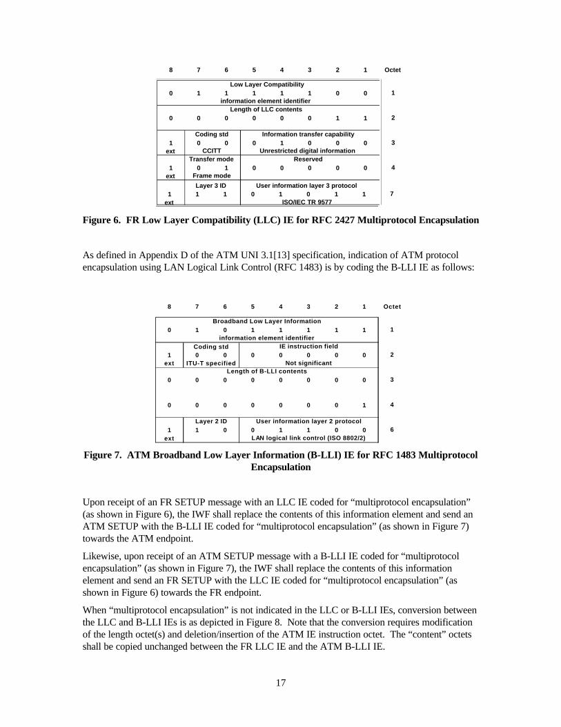
4.8 Multiprotocol Encapsulation Interworking For FR/ATM SVC service interworking, the interworking function (IWF) must determine whether to transport data frames transparently across the IWF, or whether data frames must be translated across the IWF between the FR (RFC 2427[11]) and ATM (RFC 1483[12]) multiprotocol encapsulation methods.
Normally, the FR Low Layer Compatibility (LLC) IE and the ATM Broadband Low Layer Information (B-LLI) IE are passed transparently in the SETUP message from the call originating entity to the addressed entity. However, the IWF shall use the information in these IEs to determine whether multiprotocol encapsulation translation is necessary.
To indicate RFC 2427 multiprotocol encapsulation, the LLC IE is coded as follows:
17
0 1 1 1 1 1 0 0
0 0 0 0 0 0 1 1
1 0 0 0 1 0 0 0ext
1 0 1 0 0 0 0 0ext
Transfer mode
Frame mode
Reserved
6 5
2
4
3Coding std Information transfer capability
CCITT Unrestricted digital information
Length of LLC contents
Octet
Low Layer Compatibility1
14 3 2
information element identifier
8 7
1 1 1 0 1 0 1 1ext
Layer 3 ID User information layer 3 protocol7
ISO/IEC TR 9577
Figure 6. FR Low Layer Compatibility (LLC) IE for RFC 2427 Multiprotocol Encapsulation
As defined in Appendix D of the ATM UNI 3.1[13] specification, indication of ATM protocol encapsulation using LAN Logical Link Control (RFC 1483) is by coding the B-LLI IE as follows:
0 1 0 1 1 1 1 1
1 0 0 0 0 0 0 0ext
0 0 0 0 0 0 0 0
0 0 0 0 0 0 0 1
1 1 0 0 1 1 0 0ext
Length of B-LLI contents
Layer 2 ID User information layer 2 protocol
LAN logical link control (ISO 8802/2)
Coding std
ITU-T specified
IE instruction field
Not significant2
3
4
6
8 7 6 5 4 3 2
information element identifier
Octet
Broadband Low Layer Information1
1
Figure 7. ATM Broadband Low Layer Information (B-LLI) IE for RFC 1483 Multiprotocol Encapsulation
Upon receipt of an FR SETUP message with an LLC IE coded for “multiprotocol encapsulation” (as shown in Figure 6), the IWF shall replace the contents of this information element and send an ATM SETUP with the B-LLI IE coded for “multiprotocol encapsulation” (as shown in Figure 7) towards the ATM endpoint.
Likewise, upon receipt of an ATM SETUP message with a B-LLI IE coded for “multiprotocol encapsulation” (as shown in Figure 7), the IWF shall replace the contents of this information element and send an FR SETUP with the LLC IE coded for “multiprotocol encapsulation” (as shown in Figure 6) towards the FR endpoint.
When “multiprotocol encapsulation” is not indicated in the LLC or B-LLI IEs, conversion between the LLC and B-LLI IEs is as depicted in Figure 8. Note that the conversion requires modification of the length octet(s) and deletion/insertion of the ATM IE instruction octet. The “content” octets shall be copied unchanged between the FR LLC IE and the ATM B-LLI IE.

18
[The basic format of the two IEs is identical; however, the ATM B-LLI allows additional octets for layer 2 HDLC negotiation and for layer 3 selection of a specific TR 9577 protocol identifier. Also, the Q.933 LLC IE allows for layer 2 “address inclusion” codepoints; the B-LLI IE sets the “address inclusion” (or “Q.933 use”) field to zeros. It is left to the endpoint device to determine whether it can support the additional B-LLI octets or codepoint differences. For example, an FRF.4/Q.933-based endpoint device would ignore an LLC IE that contained additional TR 9577 protocol identifier octets based on IE length or invalid content and would optionally send a STATUS message with cause #43 “access information discarded”.]
0 1 0 1 1 0 1 1
1ext
0 1 1 1 1 1 0 0
Octet
Broadband Low Layer Information1
1
Coding standard IE instruction field
8 7 6 5 4 3 2
Length of B-LLI contents (N)
N+4
4
5
2
3Low Layer Compatibility
Length of LLC contents (N)
1
2
3
N+2
8 7 6 5 4 3 2 1 Octet
Figure 8. FR LLC/ ATM B-LLI IE Conversion When Multiprotocol Encapsulation Is Not Indicated
Note that both FR and ATM SVC signaling support negotiation of the LLC/B-LLI IE in the CONNECT message either by negotiating HDLC parameters for a single B-LLI IE or by selecting one LLC/B-LLI IE from up to 3 LLC/B-LLI IEs received in the SETUP message. The IWF must support this LLC/B-LLI negotiation as specified in the following paragraphs.

19
ATMNetwork
ATMNetwork
FR-UNIFR-CPE
PNNI
IWF
IWF
FRNetworkFR-CPE
FR-UNI FR-NNI
LLC 2427
LLC “A”
LLC “B”
B-LLI 1483
B-LLI “A”
B-LLI “B”
LLC 2427
LLC “A”
LLC “B”
FR SETUP ATM SETUP FR SETUP
LLC 2427 B-LLI 1483 LLC 2427
FR CONNECT ATM CONNECT FR CONNECT
TranslateMultiprotocolData Frames
TranslateMultiprotocolData Frames
or
No LLC
or
No B-LLI
or
No LLC
LLC “A” B-LLI “A” LLC “A”Transparently
TransferData Frames
TransparentlyTransfer
Data Frames
or
LLC “B”
or
B-LLI “B”
or
LLC “B”
ororor
Figure 9. FR LLC /ATM B-LLI Negotiation Interworking (with Multiprotocol Encapsulation Preferred)
Figure 9 depicts the case in which one or more LLC/B-LLI IEs are signaled in the SETUP message. The IEs are always in preferential order and, for this case, the preferred selection is “multiprotocol encapsulation”. (Note that the IWF translates each LLC/B-LLI IE in the SETUP and CONNECT messages as previously discussed.) Based on the LLC/B-LLI selected by the destination CPE in the CONNECT message, the IWF must determine whether data frames must undergo multiprotocol encapsulation translation or must be carried transparently. As shown in the figure, the IWF must perform multiprotocol encapsulation translation of the data frames if:
• the CPE explicitly signals an LLC/B-LLI IE encoded for multiprotocol encapsulation in the CONNECT message, or
• the CPE implicitly selects LLC/B-LLI IE by omitting the LLC/B-LLI IE in the CONNECT message
Encapsulation translations shall be as defined in FRF.8.1. Otherwise, the IWF shall transfer the data frames transparently.

20
ATMNetwork
ATMNetwork
FR-UNIFR-CPE
PNNI
IWF
IWF
FRNetworkFR-CPE
FR-UNI FR-NNI
LLC 2427
LLC “A”
LLC “B”
B-LLI 1483
B-LLI “A”
B-LLI “B”
LLC 2427
LLC “A”
LLC “B”
FR SETUP ATM SETUP FR SETUP
LLC 2427 B-LLI 1483 LLC 2427
FR CONNECT ATM CONNECT FR CONNECT
TranslateMultiprotocolData Frames
TranslateMultiprotocolData Frames
or
No LLC
or
No B-LLI
or
No LLC
LLC “A” B-LLI “A” LLC “A”Transparently
TransferData Frames
TransparentlyTransfer
Data Frames or
LLC “B”
or
B-LLI “B”
or
LLC “B”
ororor
Figure 10. FR LLC /ATM B-LLI Negotiation Interworking (with Multiprotocol Encapsulation Not Preferred)
Figure 10 depicts the case in which one or more LLC/B-LLI IEs are signaled in the SETUP message but, for this case, the preferred selection is not “multiprotocol encapsulation”. As shown in the figure, the IWF must perform multiprotocol encapsulation translation of the data frames if:
• the CPE explicitly signals an LLC/B-LLI IE encoded for multiprotocol encapsulation in the CONNECT message
Encapsulation translations shall be as defined in FRF.8.1. Otherwise, the IWF shall transfer the data frames transparently.
When there are no LLC/B-LLI IEs signaled in the SETUP message, the IWF shall transfer the data frames transparently.

21
5.0 Frame Relay/ATM SVC Signaling Message Translation This section defines the signaling message translations to be performed between the FRF.10.1 and ATM PNNI signaling protocols. It contains four subsections which cover call establishment and call clearing from both the Frame Relay network and the ATM network perspectives:
• Frame Relay Initiated Call Establishment • Frame Relay Initiated Call Clearing • ATM Initiated Call Establishment • ATM Initiated Call Clearing
A message flow figure is provided within each of the following subsections. Each of these figures depicts message flow between the Frame Relay network and the ATM network.
Message translation summary tables are also provided within each of the following subsections. In each of these tables, the signaling information elements for a message are listed for the FRF.10.1 (left-most columns) and the ATM PNNI (right-most columns) protocols. The center column (labeled “Translation Description”) defines the direction of message flow (Frame Relay -> ATM, or Frame Relay <- ATM) and a short summary of how the information elements are to be translated. A more detailed explanation of the translations can be found in the accompanying text.
The signaling translations are defined above the layer 3 signaling protocols. The layer 3 FRF.10.1 and ATM PNNI protocols still provide call state, message, and information element validation processing. The service interworking requirements provided in this section are in addition to layer 3 processing.
It is assumed that the layer 3 signaling protocols handle the mechanics of translating FRF.10.1 messages to PNNI messages by:
1. Inserting the message type instruction octet (containing the flag and action indicator fields) and the 2-octet message length for each PNNI message; and
2. Inserting the IE instruction octet and the 2-octet IE length for each PNNI information element.
In the reverse translation, from PNNI to FRF.10.1:
1. A single message type octet is generated (with no message length octets) for each FRF.10.1 message; and
2. A single IE length octet is generated (and no IE instruction octet) for each FRF.10.1 information element.
Only messages of “global” (or “end-to-end”) significance require translation across the IWF. These include:
• CONNECT • RELEASE • The cause information contained in RELEASE COMPLETE (as the first clearing
message) • SETUP
While ALERTING, NOTIFY, and PROGRESS have global significance within an ATM network, they are not supported by FRF.10.1 and cannot be transferred by the IWF into the Frame Relay network.

22
Messages of “local” significance do not require translation. These include:
• CALL PROCEEDING • RELEASE COMPLETE (as a response to the RELEASE message) • STATUS • STATUS ENQUIRY • RESTART • RESTART ACKNOWLEDGE

23
5.1 Frame Relay Initiated Call Establishment Figure 11 illustrates the call establishment message flow from the FR-CPE to the ATM B-CPE.
FRNETWORK
FR-CPE IWF ATMNETWORK
B-CPE
SETUP
SETUP
SETUP
SETUP
PROC
PROC
PROC
PROC
ALERT/PROG/NOTIFY
ALERT/PROG/NOTIFY
IWF
FR Network ATM NetworkFR-CPEFR-UNI ATM-UNI
B-CPEFR-NNI ATM-NNI
Forward Direction (Calling User to Called User)
Backward Direction (Called User to Calling User)Outgoing Incoming
Preceding Side Succeeding Side
CONN
CONN
CONN
CONN
NOTIFY
NOTIFY
CONN ACK
Figure 11. Frame Relay Initiated Call Establishment Message Flow

24
5.1.1 Setup Message Translation (Frame Relay -> ATM at IWF) Upon receipt of a Frame Relay SETUP message, the IWF shall ignore the FRF.10.1 information elements listed as “No ATM Equivalent - Ignore” in Table 4, since they have no ATM NNI equivalent. However, in the case of the FRF.10.1 CUG Interlock Code, if the CUG indication (octet 3) does not indicate “closed user group with outgoing access selection and indication”, the call shall be cleared with cause #29 “facility rejected”.
In the ATM SETUP message to be sent, the IWF shall not use the ATM PNNI information elements listed as “Not Used” in Table 4.
In the ATM SETUP message to be sent, the ATM NNI Connection Identifier information element shall be created if the IWF is configured with a higher node identifier than its peer node on the PNNI interface.
The following ATM NNI information elements will be included in the SETUP message, as described in the subparagraphs of this section 5.1.1:
• Broadband Bearer Capability • Designated Transit List • Quality of Service Parameter • AAL Parameters • ATM Traffic Descriptor • Minimum Acceptable ATM Traffic Descriptor • Broadband Repeat Indicator • Broadband Low Layer Information • Calling Party Number • Calling Party Subaddress • Called Party Number • Called Party Subaddress • Calling Party SPVCC • Called Party SPVCC • Transit Network Selection (not translatable)

25
Table 4. SETUP Translation Summary for Frame Relay Initiated Call Establishment
FRF.10.1 FR -> ATM PNNISETUP Info Element Translation Summary SETUP Info Element
DLCI Save at IWFHigher Node ID Sets at IWF Connection IdentifierMandatory - IWF Provided Broadband Bearer CapabilityMandatory - IWF Provided Designated Transit ListMandatory - IWF Provided QoS Parameter
LL Core Parameters Translate AAL ParametersLL Core Parameters Translate - Mandatory ATM Traffic DescriptorPriority and Service Class ParametersTranslate-Mandatory ATM Traffic DescriptorLL Core Parameters Translate Min Accept ATM Traffic Descriptor
IWF Provided For Multiple B-LLI IEs Broadband Repeat IndicatorLow Layer Compatibility Translate Broadband Low Layer InfoCalling Party Number Translate Calling Party NumberCalling Party Subaddress Translate Calling Party SubaddressCalled Party Number Translate - Mandatory Called Party NumberCalled Party Subaddress Translate Called Party SubaddressCalling Party SPVC Translate Calling Party SPVCCCalled Party SPVC Translate Called Party SPVCCTransit Network Selection Not Translatable - Clear Call Transit Network Selection
Bearer Capability No ATM Equivalent - IgnoreUser-User No ATM Equivalent - IgnoreTransit Network Identification No ATM Equivalent - IgnoreCUG Interlock Code No ATM Equivalent - IgnoreCall Identification No ATM Equivalent - Ignore
Not Used Broadband High Layer InfoNot Used Endpoint ReferenceImplementation Dependent ABR Additional ParametersImplementation Dependent ABR Setup ParametersNot Used Alternate ATM Traffic DescriptorNot Used Connection Scope SelectionNot Used End-to-End Transit DelayNot Used Extended QoSNot Used Generic Identifier TransportNot Used Notification Indicator
5.1.1.1 ATM Connection Identifier IE If the IWF has a higher ATM node identification value that its PNNI peer node, this IE is mandatory and must be provided by the IWF in the outgoing SETUP message. See section 4.1.
5.1.1.2 ATM Broadband Bearer Capability IE This mandatory IE must be provided by the IWF in the outgoing SETUP message. It is to be coded as follows:
• Bearer Class BCOB-C • Susceptibility to Clipping Not Susceptible To Clipping • User Plane Connection Configuration Point-to-Point
Refer to section 5.1.1.6 for tranlation of the FR Priority and Service Class Parameters IE to obtain the ATM service category. If the derived ATM service category is non-real-time VBR or UBR (with the Best Effort Indicator signaled in the ATM Traffic Descriptor IE), octet 5a, ATM Transfer Capability, may be omitted since the Bearer Class is BCOB-C. For indicating real-time VBR, the ATM Transfer Capability shall be included in octet 5a.
Handling of ABR signaling is implementation dependent.

26
5.1.1.3 ATM Designated Transit List IE This mandatory IE must be provided by the IWF in the outgoing SETUP message. See section 4.5.
5.1.1.4 ATM Quality of Service Parameter IE This mandatory IE must be provided by the IWF in the outgoing SETUP message. The QoS Class Forward and QoS Class Backward values shall be set to QoS Class 0, “unspecified”.
5.1.1.5 ATM AAL Parameters IE In the outgoing SETUP message’s ATM AAL Parameters IE, the IWF shall indicate AAL Type 5 in accordance with FRF.8.1. The Forward and Backward Maximum CPCS-SDU sizes shall be set to the values provided in the Frame Relay Link Layer Core Parameters IE Outgoing and Incoming Maximum FMIF Size fields, respectively.
The SSCS Type shall be set to NULL in accordance with FRF.8.1.
5.1.1.6 ATM Traffic Descriptor IE This mandatory IE must be provided by the IWF in the outgoing SETUP message. The ATM Traffic Descriptor IE shall be generated using the Frame Relay Link Layer Core Parameters IE as defined in Annex A and section 4.3 of this document.
The algorithms in Annex A for determining ATM traffic conformance parameters require an estimate of frame size. The frame size parameter shall be configurable at the IWF.
The other fields of the ATM Traffic Descriptor IE shall be coded as follows:
• Forward Frame Discard Frame Discard Allowed • Backward Frame Discard Frame Discard Allowed • Tagging Forward Tagging Requested • Tagging Backward Tagging Requested
By default the ATM Traffic Descriptor IE should be formatted for VBR.3 conformance and the Best Effort Indicator should not be indicated since the default ATM service category is non-real-time VBR.
If the IWF supports translation of the FR Priority and Service Class Parameters IE, it is suggested that the mapping from the FR Priority and Service Class Parameters IE to the ATM Service Categories be configurable at the IWF. A suggested mapping is shown in Table 5. For example, if X.146 Service Class 0 is received, the IWF should format the ATM Traffic Descriptor IE as UBR.2 and the Best Effort Indicator should be indicated.

27
Table 5. Suggested Mapping of X.146 Service Class to ATM Service Category
FR X.146 Service Class ATM Service Category
0 UBR
1 Reserved for ABR
2 VBRnrt
3 VBRrt
Translation of the Transfer and Discard Priorities in the FR Priority and Service Class Parameters IE is outside the scope of this implementation agreement.
5.1.1.7 ATM Minimum Acceptable Traffic Descriptor IE This IE may be provided by the IWF if the Frame Relay Link Layer Core Parameters IE includes the Minimum Acceptable Throughput. The Minimum Acceptable ATM Traffic Descriptor IE is generated as in section 5.1.1.6 except that the Minimum Acceptable Throughput and not the Throughput from the Frame Relay Link Layer Core Parameters IE is used. See Annex A and section 4.3 of this document.
5.1.1.8 ATM Broadband Repeat Indicator IE and Broadband Low Layer Information IE FRF.10.1 provides for specification of the user information layer 2 and layer 3 protocols in up to three Frame Relay Low Layer Compatibility IEs. If one or more Low Layer Compatibility IEs are present in the received SETUP message, each shall be translated into an ATM Broadband Low Layer Information IE as defined in section 4.8. If multiple FR Low Layer Compatibility IEs are present in the SETUP message, the IWF shall precede the ATM Broadband Low Layer Information IEs with an ATM Broadband Repeat Indicator IE.
5.1.1.9 ATM Calling Party Number IE Translation of the Calling Party Number IE from Frame Relay to ATM is defined in section 4.2.1. Translation of the number plan of the Frame Relay Calling Party Number may not be supported by the IWF. Since this IE isn’t mandatory, an unsupported address simply won’t be forwarded by the IWF.
5.1.1.10 ATM Calling Party Subaddress IE Translation of the Calling Party Subaddress IE from Frame Relay to ATM is defined in section 4.2.2.
5.1.1.11 ATM Called Party Number IE Translation of the Called Party Number IE from Frame Relay to ATM is defined in section 4.2.1. Translation of the number plan of the Frame Relay Called Party Number may not be supported by

28
the IWF. Since this is a mandatory IE, an unsupported address received in a SETUP message is to be rejected with cause #100 “invalid information element contents”.
5.1.1.12 ATM Called Party Subaddress IE Translation of the Called Party Subaddress IE from Frame Relay to ATM is defined in section 4.2.2.
5.1.1.13 ATM Calling Party SPVCC IE This IE must be provided by the IWF if the Frame Relay Calling Party SPVC IE is received in the Frame Relay SETUP message. See section 4.4.
5.1.1.14 ATM Called Party SPVCC IE This IE must be provided by the IWF if the Frame Relay Called Party SPVC IE is received in the Frame Relay SETUP message. See section 4.4.
5.1.1.15 ATM Transit Network Selection IE This IE cannot be translated from the first Frame Relay Transit Network Selection (TNS) IE if present in the received SETUP message. The codepoints used by FRF.10.1 (X.76) and PNNI are as follows:
Table 6. Transit Network Selection Type and Plan Codepoints
Network ID Type Network ID Plan
FRF.10.1 International Carrier ID Code (E.164 Country Code), or
X.121 Data Network ID Code
PNNI National Carrier ID Code
Note that the “network ID type” codepoints don’t match. If a Frame Relay Transit Network Selection IE is received, then the call shall be cleared by the IWF with cause #100 “invalid information element contents”.
5.1.2 Call Proceeding Message Handling (Frame Relay <- ATM at IWF) As listed in Table 7, upon receipt of a Frame Relay SETUP message at the IWF, the IWF responds with a CALL PROCEEDING message.
After sending an ATM SETUP message, the IWF should receive a CALL PROCEEDING message from the ATM network. If the IWF is attached to an ATM node with a higher node identifier, the VPI/VCI value for the SVC is received in the Connection Identifier IE. If an Endpoint Reference IE is received in the ATM CALL PROCEEDING message, the call shall be cleared since multipoint functionality is not supported by the IWF.
Note that CALL PROCEEDING is of “local” significance and shall be issued by the IWF only upon receipt of a SETUP message.

29

30
Table 7. CALL PROCEEDING Handling Summary for Frame Relay Initiated Call Establishment
FRF.10.1 FR <- ATM PNNICALL PROC Info Element Handling Summary CALL PROC Info Element
DLCI Mandatory - Duplicate of SETUP DLCILower Node ID Saves at IWF Connection IdentifierNo FR Equivalent - Clear Call Endpoint Reference
5.1.2.1 Frame Relay Data Link Connection Identifier IE The Frame Relay DLCI value must be provided in the outgoing CALL PROCEEDING message. It shall be identical to that received in the Frame Relay SETUP message. See section 4.1.
5.1.3 Alerting Message Handling (Frame Relay <- ATM at IWF) The ALERTING message is not supported by FRF.10.1. If received from the ATM network, this message shall not be forwarded by the IWF to the Frame Relay network.
5.1.4 Progress Message Handling (Frame Relay <- ATM at IWF) The PROGRESS message is not supported by FRF.10.1. If received from the ATM network, this message shall not be forwarded by the IWF to the Frame Relay network.
5.1.5 Notify Message Handling (Frame Relay <- ATM at IWF) The NOTIFY message is not supported by FRF.10.1. If received from the ATM network, this message shall not be forwarded by the IWF to the Frame Relay network.

31
5.1.6 Connect Message Translation (Frame Relay <- ATM at IWF) Upon receipt of an ATM CONNECT message, the IWF shall ignore the ATM PNNI information elements listed as “No FR Equivalent - Ignore” in Table 8, since they have no FRF.10.1 equivalent.
Handling of ABR signaling is implementation dependent. If an Endpoint Reference IE is received in the CONNECT message, the call shall be cleared with cause #99 “information element/parameter non-existent or not implemented” since multipoint functionality is not supported by the IWF.
In the Frame Relay CONNECT message to be sent, the IWF shall not use the FRF.10.1 information elements listed as “Not Used
The following FRF.10.1 information elements will be included in the CONNECT message by translating the ATM NNI information elements, as described in the following subparagraphs:
• Connected Number • Connected Subaddress • Link Layer Core Parameters • Called Party SPVCC • Low Layer Compatibility

32
Table 8. CONNECT Translation Summary for Frame Relay Initiated Call Establishment
FRF.10.1 FR <- ATM PNNICONNECT Info Element Translation Summary CONNECT Info Element
Connected Number Translate Connected NumberConnected Subaddress Translate Connected SubaddressLink Layer Core Parameters Mandatory - Translate ATM Traffic DescriptorLink Layer Core Parameters Mandatory - Translate AAL ParametersCalled Party SPVC Translate Called Party SPVCCLow Layer Compatibility Translate Broadband Low Layer Info
User-User Not UsedTransit Network Identification Not Used
No FR Equivalent - Ignore Generic Identifier TransportNo FR Equivalent - Ignore Notification IndicatorImplementation Dependent ABR Additional ParametersImplementation Dependent ABR Setup ParametersNo FR Equivalent - Clear Call End-to-End Transit DelayNo FR Equivalent - Clear Call Extended QoS ParametersNo FR Equivalent - Clear Call Endpoint Reference
5.1.6.1 Frame Relay Connected Number IE Translation of the Connected Number IE from ATM to Frame Relay is defined in section 4.2.1. Translation of the number plan of the ATM Connected Number may not be supported by the IWF. Since this IE isn’t mandatory, an unsupported address simply won’t be forwarded by the IWF.
5.1.6.2 Frame Relay Connected Subaddress IE Translation of the Connected Subaddress IE from ATM to Frame Relay is defined in section 4.2.2. The ATM Endsystem Address (AESA) coding of the ATM Connected Subaddress is not supported since there is no direct FRF.10.1 equivalent. Since this IE isn’t mandatory, an AESA address simply won’t be forwarded by the IWF.
5.1.6.3 Frame Relay Link Layer Core Parameters IE This mandatory IE shall be generated by the IWF for the outgoing CONNECT message. If the ATM AAL Parameters IE is received in the ATM CONNECT message, the Frame Relay Link Layer Core Parameters IE Outgoing and Incoming FMIF Size fields shall be set to the Forward and Backward Maximum CPCS-SDU Sizes, respectively. If the ATM Traffic Descriptor IE is received in the ATM CONNECT message, the Frame Relay CIR, Bc, and Be values shall be calculated according to the algorithms defined in Annex A. See section 4.3.
If the AAL Parameters IE does not indicate AAL Type 5, the call shall be rejected with cause #100 “invalid information element contents”.
If the AAL Parameters IE is not present in the ATM CONNECT message, the IWF shall set the Frame Relay Link Layer Core Parameters IE Outgoing and Incoming FMIF Size fields to the values previously sent in the FR SETUP message.
If the ATM Traffic Descriptor IE is not present in the ATM CONNECT message, the IWF shall set the Frame Relay Link Layer Core Parameters IE CIR, Bc, and Be fields to the values previously sent in the FR SETUP message.

33
5.1.6.4 Frame Relay Called Party SPVC IE This IE shall be translated by the IWF if the ATM Called Party SPVCC IE is received in the ATM CONNECT message. See section 4.4.
5.1.6.5 Frame Relay Low Layer Compatibility IE This IE shall be translated by the IWF if the ATM Broadband Low Layer Information IE is received in the ATM CONNECT message. See section 4.8.

34
5.2 Frame Relay Initiated Call Clearing Figure 12 illustrates the call clearing message flow from the Frame Relay network to the ATM network. Tables 9 and 10 summarize the translation of these messages at the IWF. Translation of cause values shall be as defined in section 4.6.
As specified in FRF.10.1, the Frame Relay network initiates call clearing with REL COMP in call state N0 and with RELEASE in all other call states. These two scenarios are reflected in Figure 12. The IWF may also initiate call clearing towards the Frame Relay network and towards the ATM network.
FRNETWORK
FR-CPE IWF ATMNETWORK
B-CPE
RELEASE
RELEASE
RELEASE
REL COMP
REL COMP
RELEASE
REL COMP
REL COMP
REL COMP
IWF
FR Network ATM NetworkFR-CPEFR-UNI ATM-UNI
B-CPEFR-NNI ATM-NNI
Forward Direction
Backward DirectionOutgoing Incoming
Preceding Side Succeeding Side
RELEASE
RELEASE
REL COMP
REL COMP
Figure 12. Frame Relay Initiated Call Clearing Message Flow

35
Table 9. RELEASE Translation Summary for Frame Relay Initiated Call Clearing
FRF.10.1 FR -> ATM PNNIRELEASE Info Element Translation Summary RELEASE Info Element
Cause (2 instances possible) Translate Cause (2 instances possible)IWF Provided Crankback
Clearing Network Identification No ATM Equivalent - IgnoreTransit Network Identification No ATM Equivalent - Ignore
Not Used Notification IndicatorNot Used Generic Identifier Transport
Table 10. RELEASE COMPLETE Translation Summary for Frame Relay Initiated Call Clearing
FRF.10.1 FR -> ATM PNNIREL COMP Info Element Translation Summary RELEASE Info Element
Cause (2 instances possible) Translate Cause (2 instances possible)IWF Provided Crankback
Clearing Network Identification No ATM Equivalent - IgnoreTransit Network Identification No ATM Equivalent - Ignore
Not Used Notification IndicatorNot Used Generic Identifier Transport

36
5.3 ATM Initiated Call Establishment Figure 13 illustrates the call establishment message flow from the ATM network to the Frame Relay network.
FRNETWORK
FR-CPE IWF ATMNETWORK
B-CPE
SETUP
SETUP
SETUP
SETUP
PROC
PROC
PROC
PROC
CONN
CONN
CONN
CONN
IWF
FR Network ATM NetworkFR-CPEFR-UNI ATM-UNI
B-CPEFR-NNI ATM-NNI
Forward Direction (Calling User to Called User)
Backward Direction (Called User to Calling User)OutgoingIncoming
Preceding SideSucceeding Side
CONN ACK
Figure 13. ATM Initiated Call Establishment Message Flow
37
5.3.1 Setup Message Translation (Frame Relay <- ATM at IWF) Upon receipt of an ATM SETUP message, the IWF shall ignore the PNNI information elements listed as “No FR Equivalent - Ignore” in Table 11, since they have no Frame Relay NNI equivalent.
If the Broadband Bearer Capability IE user plane field is not set to “point-to-point”, the call shall be rejected with cause #100 “invalid information element contents”, because FRF.10.1 does not support point-to-multipoint connections.
The Frame Relay network is not capable of supporting the CBR or ABR service categories. Rules for decoding ATM service categories from the PNNI Broadband Bearer Capability IE are defined in section 2.0 “Basic Point-to-Point Call” (paragraph 4.5.7/Q.2931 Broadband bearer capability). If the PNNI SETUP message Broadband Bearer Capability IE indicates either CBR or ABR, the call shall be rejected with cause #99 “information element not implemented”:
Handling of ABR signaling is implementation dependent. Since FRF.10.1 does not support point-to-multipoint connections, receipt of an ATM Endpoint Reference IE in the SETUP message shall result in the call shall be rejected with cause #99 “information element/parameter non-existent or not implemented”.
In the Frame Relay SETUP message to be sent, the IWF shall not use the FRF.10.1 information elements listed as “Not Used” in Table 11.
In the Frame Relay SETUP message to be sent, the Data Link Connection Identifier information element shall be created by the IWF as defined in section 4.1.
The following FRF.10.1 information elements will be included in the SETUP message, as described in the subparagraphs of this section 5.3.1:
• Bearer Capability • Link Layer Core Parameters • Low Layer Compatibility • Calling Party Number • Calling Party Subaddress • Called Party Number • Called Party Subaddress • Calling Party SPVC • Called Party SPVC • Transit Network Selection (not translatable) • Call Identification • Priority and Service Class Parameters

38
Table 11. SETUP Translation Summary for ATM Initiated Call Establishment
FRF.10.1 FR <- ATM PNNISETUP Info Element Translation Summary SETUP Info Element
DLCI Mandatory - Set at IWFLower Node ID Saves at IWF Connection Identifier
Bearer Capability Mandatory - IWF ProvidedLL Core Parameters Translate - Mandatory AAL ParametersLL Core Parameters Translate - Mandatory ATM Traffic DescriptorLL Core Parameters Translate Min Accept ATM Traffic DescriptorLow Layer Compatibility Translate Broadband Low Layer InfoCalling Party Number Translate - Mandatory Calling Party NumberCalling Party Subaddress Translate Calling Party SubaddressCalled Party Number Translate - Mandatory Called Party NumberCalled Party Subaddress Translate Called Party SubaddressCalling Party SPVC Translate Calling Party SPVCCCalled Party SPVC Translate Called Party SPVCCTransit Network Selection Not Translatable - Clear Call Transit Network SelectionCall Identification Create - MandatoryPriority and Service Class Parameters Translate ATM Traffic Descriptor
User-User Not UsedTransit Network Identification Not UsedCUG Interlock Code Not Used
No FR Equivalent - Validate Broadband Bearer CapabilityNo FR Equivalent - Ignore QoS ParameterNo FR Equivalent - Ignore Alternate ATM Traffic DescriptorNo FR Equivalent - Ignore Broadband High Layer InfoNo FR Equivalent - Ignore Broadband Repeat IndicatorNo FR Equivalent - Ignore Connection Scope SelectionNo FR Equivalent - Ignore Designated Transit ListNo FR Equivalent - Ignore Generic Identifier TransportNo FR Equivalent - Ignore Notification IndicatorImplementation Dependent ABR Additional ParametersImplementation Dependent ABR Setup ParametersNo FR Equivalent - Clear Call End-to-End Transit DelayNo FR Equivalent - Clear Call Extended QoSNo FR Equivalent - Clear Call Endpoint Reference
5.3.1.1 Frame Relay Data Link Connection Identifier IE This mandatory IE must be provided by the IWF in the outgoing SETUP message. See section 4.1.
5.3.1.2 Frame Relay Bearer Capability IE This mandatory IE must be provided by the IWF in the outgoing SETUP message. It shall be coded as follows as defined by FRF.10.1:
• Coding Standard CCITT • Information Transfer Capability Unrestricted Digital Information • Transfer Mode Frame Mode • User Information Layer 2 Protocol Core Aspects of Frame Mode (Annex A/Q.922)
5.3.1.3 Frame Relay Link Layer Core Parameters This mandatory IE must be provided by the IWF in the outgoing SETUP message.

39
If the ATM AAL Parameters IE is received in the ATM SETUP message, it shall be used to generate the Frame Relay Link Layer Core Parameters IE for the outgoing Frame Relay SETUP message. The Frame Relay Link Layer Core Parameters IE Outgoing and Incoming FMIF Size fields shall be set to the Forward and Backward Maximum CPCS-SDU Sizes, respectively. If the ATM AAL Parameters IE is not received, IWF default values shall be used.
If the AAL Parameters IE does not indicate AAL Type 5, the call shall be rejected with cause #100 “invalid information element contents”.
The Frame Relay traffic conformance parameters (CIR, Bc, and Be) shall be generated using the ATM Traffic Descriptor IE. If present, the Minimum Acceptable ATM Traffic Descriptor IE may be used to generate the Frame Relay minimum acceptable CIR. See section 4.3 and Annex A of this document.
The algorithms in Annex A for determining the Frame Relay traffic conformance parameters require an estimate of frame size. The frame size parameter shall be configurable at the IWF.
5.3.1.4 Frame Relay Low Layer Compatibility IE ATM NNI provides for specification of the user information layer 2 and layer 3 protocols in the ATM Broadband Low Layer Information (B-LLI) IE. Up to 3 B-LLI IEs may be present in the ATM SETUP message. If one or more IEs are present in the received ATM SETUP message, each B-LLI IE shall be translated into a Frame Relay Low Layer Compatibility IE as defined in section 4.8.
5.3.1.5 Frame Relay Calling Party Number IE This mandatory IE must be provided by the IWF in the outgoing SETUP message. If the ATM Calling Party Number IE is not included in the received SETUP message, the IWF shall generate a FR Calling Party Number IE with the Presentation Indicator set to “number not avScreening Indicator set to “network provided”.
Translation of the Calling Party Number IE from ATM to Frame Relay is defined in section 4.2.1.
Translation of the number plan of the ATM Calling Party Number may not be supported by the IWF. Since this is a mandatory IE, an unsupported address received in a SETUP message is to be rejected with cause #100 “invalid information element contents”.
5.3.1.6 Frame Relay Calling Party Subaddress IE Translation of the Calling Party Subaddress IE from ATM to Frame Relay is defined in section 4.2.2. The ATM Endsystem Address (AESA) coding of the ATM Calling Party Subaddress is not supported since there is no direct FRF.10.1 equivalent. Since this IE isn’t mandatory, an AESA
arded by the IWF.
5.3.1.7 Frame Relay Called Party Number IE This mandatory IE must be provided by the IWF in the outgoing SETUP message.
Translation of the Called Party Number IE from ATM to Frame Relay is defined in section 4.2.1.
Translation of the number plan of the ATM Called Party Number may not be supported by the IWF. Since this is a mandatory IE, when an unsupported address is received in a SETUP message, it shall be rejected with cause #100 “invalid information element contents”.

40
5.3.1.8 Frame Relay Called Party Subaddress IE Translation of the Called Party Subaddress IE from ATM to Frame Relay is defined in section 4.2.2. The ATM Endsystem Address (AESA) coding of the ATM Called Party Subaddress is not supported since there is no direct FRF.10.1 equivalent. Since this IE isn’t mandatory, an AESA address simply won’t be forwarded by the IWF.
5.3.1.9 Frame Relay Calling Party SPVC IE This IE is provided by the IWF if the ATM Calling Party SPVCC IE is received in the ATM SETUP message. See section 4.4.
5.3.1.10 Frame Relay Called Party SPVC IE This IE shall be provided by the IWF if the ATM Called Party SPVCC IE is received in the ATM SETUP message. See section 4.4.
5.3.1.11 Frame Relay Transit Network Selection IE This IE cannot be translated from the ATM Transit Network Selection IE if present in the received SETUP message. The codepoints used by FRF.10.1 (X.76) and PNNI are as defined in Table 6 of section 5.1.1.15.
Note that the “network ID type” codepoints don’t match. If the ATM Transit Network Selection IE is received, then the call shall be cleared by the IWF with cause #100 “invalid information element contents”.
5.3.1.12 Frame Relay Call Identification IE The Call Identification shall be created by the IWF. It is a unique identifier created by the originating network and passed unchanged by intermediate and the terminating network(s).
5.3.1.13 Frame Relay Priority and Service Class Parameters IE If the IWF supports translation of the FR Priority and Service Class Parameters IE, it is suggested that the mapping from the FR Priority and Service Class Parameters IE to the ATM Service Categories be configurable at the IWF. A suggested mapping is shown in Table 5 in section 5.1.1.6. For example, if the Best Effort Indicator is received in the ATM Traffic Descriptor IE (indicating a UBR ATM service category), the IWF should indicate X.146 Service Class 0 in the FR Priority and Service Class Parameters IE.
By default, the FR Priority and Service Class Parameters IE should indicate X.146 Service Class 1 since the default ATM service category is non-real-time VBR.
Translation of the Transfer and Discard Priorities in the FR Priority and Service Class Parameters IE is outside the scope of this implementation agreement.

41
5.3.2 Call Proceeding Message Handling (Frame Relay -> ATM at IWF) As listed in Table 12, upon receipt of an ATM SETUP message, the IWF responds with a CALL PROCEEDING message. After sending a Frame Relay SETUP message, the IWF receives a CALL PROCEEDING message.
In the ATM CALL PROCEEDING message to be sent, the VPI/VCI value in the Connection Identifier IE shall be generated by the IWF if it is attached to an ATM node with a lower node identifier. If the IWF is attached to an ATM node with a higher node identifier, it shall echo the VPI/VCI value previously received in the ATM SETUP message.
Since FRF.10.1 does not support point-to-multipoint connections, the ATM Endpoint Reference IE shall not be used.
Note that CALL PROCEEDING is of “local” significance and is issued by the IWF only upon receipt of a SETUP message.
Table 12. CALL PROCEEDING Handling Summary for ATM Initiated Call Establishment
FRF.10.1 FR -> ATM PNNICALL PROC Info Element Handling Summary CALL PROC Info Element
DLCI Duplicate of SETUP DLCIMandatory - Higher Node ID Sets at IWF; or Lower Node ID Reuses SETUP Connection ID Connection IdentifierNot Used Endpoint Reference
5.3.2.1 ATM Connection Identifier IE The VPI/VCI value must be provided in the outgoing CALL PROCEEDING message. See section 4.1.
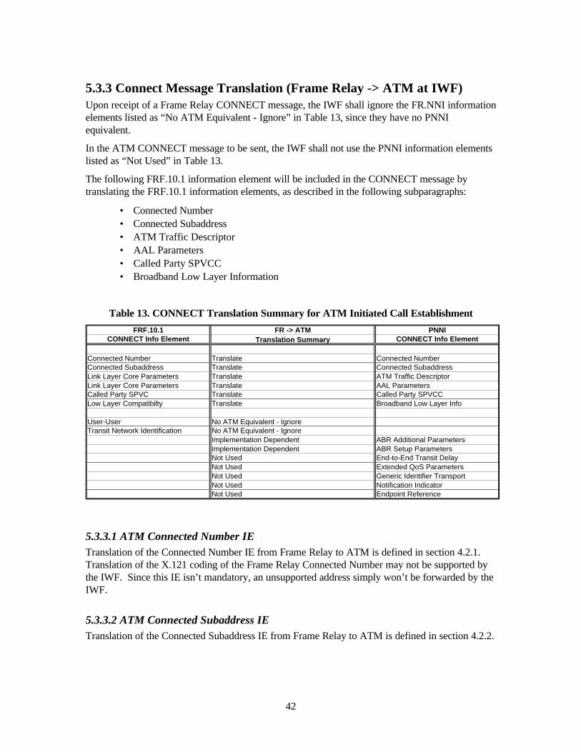
42
5.3.3 Connect Message Translation (Frame Relay -> ATM at IWF) Upon receipt of a Frame Relay CONNECT message, the IWF shall ignore the FR.NNI information elements listed as “No ATM Equivalent - Ignore” in Table 13, since they have no PNNI equivalent.
In the ATM CONNECT message to be sent, the IWF shall not use the PNNI information elements listed as “Not Used” in Table 13.
The following FRF.10.1 information element will be included in the CONNECT message by translating the FRF.10.1 information elements, as described in the following subparagraphs:
• Connected Number • Connected Subaddress • ATM Traffic Descriptor • AAL Parameters • Called Party SPVCC • Broadband Low Layer Information
Table 13. CONNECT Translation Summary for ATM Initiated Call Establishment
FRF.10.1 FR -> ATM PNNICONNECT Info Element Translation Summary CONNECT Info Element
Connected Number Translate Connected NumberConnected Subaddress Translate Connected SubaddressLink Layer Core Parameters Translate ATM Traffic DescriptorLink Layer Core Parameters Translate AAL ParametersCalled Party SPVC Translate Called Party SPVCCLow Layer Compatibilty Translate Broadband Low Layer Info
User-User No ATM Equivalent - IgnoreTransit Network Identification No ATM Equivalent - Ignore
Implementation Dependent ABR Additional ParametersImplementation Dependent ABR Setup ParametersNot Used End-to-End Transit DelayNot Used Extended QoS ParametersNot Used Generic Identifier TransportNot Used Notification IndicatorNot Used Endpoint Reference
5.3.3.1 ATM Connected Number IE Translation of the Connected Number IE from Frame Relay to ATM is defined in section 4.2.1. Translation of the X.121 coding of the Frame Relay Connected Number may not be supported by the IWF. Since this IE isn’t mandatory, an unsupported address simply won’t be forwarded by the IWF.
5.3.3.2 ATM Connected Subaddress IE Translation of the Connected Subaddress IE from Frame Relay to ATM is defined in section 4.2.2.

43
5.3.3.3 ATM Traffic Descriptor IE The ATM Traffic Descriptor IE shall be generated using the Frame Relay Link Layer Core Parameters IE as defined in Annex A and section 4.3 of this document.
The algorithms in Annex A for determining ATM traffic conformance parameters require an estimate of frame size. The frame size parameter shall be configurable at the IWF.
The other fields of the ATM Traffic Descriptor IE shall be coded as follows:
• Forward Frame Discard Frame Discard Allowed • Backward Frame Discard Frame Discard Allowed • Tagging Forward Tagging Requested • Tagging Backward Tagging Requested
5.3.3.4 ATM AAL Parameters In the outgoing CONNECT message’s ATM AAL Parameters IE, the IWF shall indicate AAL Type 5 in accordance with FRF.8.1. The Forward and Backward Maximum CPCS-SDU sizes shall be set to the values provided in the Frame Relay Link Layer Core Parameters IE Outgoing and Incoming Maximum FMIF Size fields, respectively.
5.3.3.5 ATM Called Party SPVCC IE This IE shall be provided by the IWF if the Frame Relay Called Party SPVC IE is received in the Frame Relay CONNECT message. See section 4.4.
5.3.3.6 ATM Broadband Low Layer Information IE This IE shall be translated by the IWF if the Frame Relay Low Layer Compatibility IE is received in the Frame Relay CONNECT message. See section 4.8.

44
5.4 ATM Initiated Call Clearing Figure 14 illustrates the call clearing message flow from the ATM network to the Frame Relay network. Tables 14 and 15 summarize the translation of these messages at the IWF. Translation of cause values shall be as defined in section 4.6.
As specified in PNNI, the ATM network initiates call clearing with REL COMP in call state U0/N0, and with RELEASE in all other call states. These two scenarios are reflected in Figure 14. The IWF may also initiate call clearing towards the Frame Relay network and towards the ATM network.
FRNETWORK
FR-CPE IWF ATMNETWORK
B-CPE
REL COMP
RELEASE
RELEASE
REL COMPRELEASE
RELEASE REL COMP
REL COMP
REL COMP
IWF
FR Network ATM NetworkFR-CPEFR-UNI ATM-UNI
B-CPEFR-NNI ATM-NNI
Forward Direction
Backward DirectionOutgoingIncoming
Preceding SideSucceeding Side
RELEASE
RELEASE REL COMP
REL COMP
Figure 14. ATM Initiated Call Clearing Message Flow

45
Table 14. RELEASE Translation Summary for ATM Initiated Call Clearing
FRF.10.1 FR <- ATM PNNIRELEASE Info Element Translation Summary RELEASE Info Element
Cause (2 instances possible) Translate Cause (2 instances possible)
Clearing Network Identification Not UsedTransit Network Identification Not Used
No FR Equivalent - Ignore CrankbackNo FR Equivalent - Ignore Notification IndicatorNo FR Equivalent - Ignore Generic Identifier Transport
Table 15. RELEASE COMPLETE Translation Summary for ATM Initiated Call Clearing
FRF.10.1 FR <- ATM PNNIRELEASE Info Element Translation Summary REL COMP Info Element
Cause (2 instances possible) Translate Cause (2 instances possible)
Clearing Network Identification Not UsedTransit Network Identification Not Used
No FR Equivalent - Ignore CrankbackNo FR Equivalent - Ignore Notification IndicatorNo FR Equivalent - Ignore Generic Identifier Transport

46
Annex A - Conversion of Traffic Parameters The Frame Relay traffic conformance parameters can be used to determine approximately equivalent ATM traffic conformance parameters, as described in this annex. Approximately equivalent Frame Relay traffic conformance parameters can be determined from ATM traffic conformance parameters, as described in this appendix.
A.1 Conversion from Frame Relay to ATM Traffic Parameters Conversion from FR to ATM VBR.3 traffic conformance parameters is performed as follows:
PCR0+1 = (CIR + EIR) * IOHR
SCR0 = CIR * IOHR
MBS0 = Bc * IOHR
Mode 1 DE-to-CLP Mapping Mode as defined in FRF.8.1.
where:
• PCR and SCR units are [cells/second],
• MBS units are [cells],
• CIR, and EIR units are [bytes/second],
• Bc and Be units are [bytes],
• EIR = Be * CIR / Bc,
• FRHS is the Frame Relay Header Size (2 or 4 bytes),
• FROH is the Frame Relay HDLC Overhead (4 bytes of CRC and Flags),
• AALHS is the AAL5 trailer size (8 bytes)
• N_Avg is the average number of user information [bytes/frame],
and
• IOHR is the Interworking Overhead Ratio [cells/byte]= ((N_Avg + AALHS)/48)/N_Avg,

47
A.2 Conversion from ATM to FR Traffic Parameters Determination of the FR traffic conformance parameters (CIR, Bc, and Be) from the ATM traffic conformance parameters is dependent on the combination of parameters received in the ATM Traffic Descriptor. Table A-1 defines the allowable combinations of ATM traffic parameters for each direction (forward and backward) and the associated mapping algorithm to determine the FR traffic parameters.
Table A-1 ATM to FR Traffic Parameters Mapping Algorithms
Allowable Combinations of ATM Traffic Parameters
Mapping Algorithm CLP-to-DE Mapping Mode (see reference [3])
PCR0+1 SCR0 MBS0 Tagging/No Tagging
CIR = SCR0 * IOHR,
EIR = (PCR0+1 - SCR0)* IOHR,
Bc = MBS0 * IOHR
Mode 1
PCR0+1 Best Effort
CIR = 0,
EIR = PCR0+1 * IOHR,
Bc = 0
Be = EIR * Tc
Mode 1
PCR0+1 CIR = PCR0+1 * IOHR,
EIR = 0,
Bc = CIR * Tc
Mode 2 with DE=0
PCR0+1 SCR0+1 MBS0+1
CIR = SCR0+1 * IOHR,
EIR = 0,
Bc = MBS0+1 * IOHR
Mode 2 with DE=0
PCR0 PCR0+1 Tagging/No Tagging
CIR = PCR0 * IOHR,
EIR = (PCR0+1 - PCR0)* IOHR,
Bc = CIR * Tc
Be = EIR * Tc
Mode 1
where:
• PCR and SCR units are [cells/second],
• MBS units are [cells],
• CIR and EIR units are [bytes/second],
• Bc and Be units are [bytes],
• Tc is a configurable time constant [seconds] = Bc/CIR,

48
• FRHS is the Frame Relay Header Size (2 or 4 bytes),
• FROH is the Frame Relay HDLC Overhead (4 bytes of CRC and Flags),
• N_Avg is the average number of user information [bytes/frame],
• IOH is the Interworking Overhead [bytes/frame] = N_Avg + FRHS + FROH,
and
• IOHR is the Interworking Overhead Ratio [bytes/cell] = IOH * 48 / N_Avg,
Notes
• All transformations leading to non-integer values should be rounded up.
• In performing the mapping from ATM to FR traffic parameters, attention is given to the two major FR functions that utilize the FR traffic parameters: (1) trunk bandwidth allocation, and (2) rate enforcement. The above transformations lead to a bandwidth allocation corresponding to either the PCR or the SCR depending on the Traffic Descriptor type. The above transformations also lead to the enforcement of a committed burst size equivalent to MBS cells if an MBS value is specified or 1 cell otherwise. All values are adjusted by the IOHR which represents an estimate of the actual number of frame relay bytes corresponding to any 1 ATM cell. It is based on the rationale that n ATM cells will be mapped into a single frame and that involves the additional overhead comprised of the FRHS and FROH bytes.

49
Annex B - Generic Application Transport (GAT) This document is an optional annex to the Network-to-Network FR/ATM SVC Service Interworking Implementation Agreement. It contains the description and specification for the Generic Application Transport (GAT) feature.
B.1 General Description Generic Application Transport (GAT) is an optional FRF.10.1 facility which supports the following functions:
a) It allows Frame Relay networks to transport organization-specific information in an interoperable manner. This is achieved by using the FRF.10.1 GAT IE which can be directly mapped to the PNNI GAT IE [17] with the “Application Type” field coded as “organization-specific”.
b) It provides a mechanism for FR/ATM interworking by allowing Frame Relay networks to tunnel FRF.10.1 information elements through PNNI networks. For example, some of the capabilities available in Frame Relay that are missing in PNNI are: • Call Identification • Transit Network Identification • Clearing Network Identification • Link Layer Core Parameters • Priority and Service Class
The information necessary to support these features need not be processed or understood by intermediate PNNI nodes, but rather only at interworking units. Hence, the approach of defining new PNNI information elements to support each of these non-PNNI features (as currently taken by ITU-T Q.2933 [18]) is undesirable. Instead, the GAT mechanism is used to “tunnel” FRF.10.1 information elements transparently between FR/ATM Inter-Working Units (IWUs) across PNNI networks.
This is achieved by using the Application Type value of “Frame Relay Forum FRF.10.1” in the PNNI GAT IE.

50
B.2 Additions to FR/ATM SVC Signalling Translations
This section defines the additional signalling translations to be performed between the Frame Relay FRF.10.1 and ATM PNNI protocols, in order to support the GAT feature.
Only messages of global significance require translation across the IWF. These include:
• SETUP
• CONNECT
• RELEASE
• RELEASE COMPLETE (as first clearing message)
B.2.1 FR to ATM Translation
When a FR GAT IE is received and the Interworking Unit does not recognize the Application Type, the following actions shall be taken:
a) If the received message is a RELEASE COMPLETE and it is not the first clearing message, no action shall be taken on the IE.
b) Otherwise, the IE shall be forwarded unchanged. If the Application Type is “FR Forum FRF.10.1” or “organization-specific”, the Interworking Unit shall perform the information element encoding and procedures for one of the following:
• Tunnelling of the FRF.10.1 information elements through a Network using the PNNI GAT IE, with the Application Type set to “FR Forum FRF.10.1”, or
• Mapping of FRF.10.1 GAT IE to PNNI GAT IE for the transport of organization-specific information, using the Application Type “Organization-specific”.
The information element encoding and procedures are described in the sub-sections below.
B.2.1.1 Tunnelling of FRF.10.1 Information Elements
Two types of FRF.10.1 information elements may be transported transparently using the PNNI GAT IE. These are described in the sub-sections below.
B.2.1.1.1 FR Information Elements With No ATM Equivalent
Table B-1 lists the FRF.10.1 IEs which may be encapsulated in the PNNI GAT IE to be sent in the corresponding PNNI Message. These IEs are currently being discarded since they have no ATM equivalents.
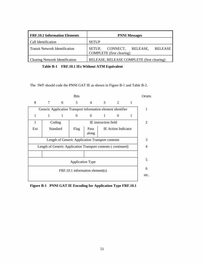
51
FRF.10.1 Information Elements PNNI Messages
Call Identification SETUP
Transit Network Identification SETUP, CONNECT, RELEASE, RELEASE COMPLETE (first clearing)
Clearing Network Identification RELEASE, RELEASE COMPLETE (first clearing)
Table B-1 FRF.10.1 IEs Without ATM Equivalent
The IWF should code the PNNI GAT IE as shown in Figure B-1 and Table B-2.
Bits Octets
8 7 6 5 4 3 2 1
Generic Application Transport information element identifier 1
1 1 1 0 0 1 0 1
1 Coding IE instruction field 2
Ext Standard Flag Pass along
IE Action Indicator
Length of Generic Application Transport contents 3
Length of Generic Application Transport contents ( continued) 4
Application Type 5
FRF.10.1 information element(s)
6
etc.
Figure B-1 PNNI GAT IE Encoding for Application Type FRF.10.1

52
Coding Standard (Octet 2)
Bits Meaning
8 7 6 5 4 3 2 1
1 1 ATM Forum specific
Flag (Octet 2)
Bits Meaning
8 7 6 5 4 3 2 1
1 Follow explicit instructions
Pass along (Octet 2)
Bits Meaning
8 7 6 5 4 3 2 1
1 Pass along request
IE Action Indicator (Octet 2)
Bits Meaning
8 7 6 5 4 3 2 1
0 0 1 Discard IE and proceed
Application Type (Octet 5)
Bits Meaning
8 7 6 5 4 3 2 1
0 0 0 0 0 1 0 0 Frame Relay Forum FRF.10.1
FRF.10.1 Information Elements (Octet 6 etc.)
One or more information elements as specified in FRF.10.1
Table B-2 PNNI GAT IE Encoding for Application Type FRF.10.1

53
B.2.1.1.2 FR Information Elements Without Direct Mapping
Table B-3 specifies the FR information elements which cannot be directly mapped to corresponding PNNI IEs. These IEs must be translated using specific mathematical calculations or various approximations. An example is the Link Layer Core Parameters information element.
It is highly recommended that these IEs be tunnelled over PNNI using the PNNI GAT IE (in addition to the translation to ATM IEs), so that the original values may be retrieved if the destination is a Frame Relay endpoint. The PNNI GAT IE should be coded as described in 0.
FRF.10.1 Information Elements PNNI Messages
Link Layer Core Parameters SETUP, CONNECT
Priority and Service Class Parameters SETUP
Table B-3 FRF.10.1 IEs Which Cannot Be Directly Mapped
B.2.1.2 Translation of FRF.10.1 GAT IE With Organization Specific Information
This section describes the mapping of the FRF.10.1 GAT IE with application type coded as organization-specific. The IWF should code the PNNI GAT IE as shown in Figure B-2 and Table B-4.

54
Bits Octets
8 7 6 5 4 3 2 1
Generic application transport information element identifier 1
1 1 1 0 0 1 0 1
1 Coding IE instruction field 2
Ext Standard Flag Pass along
IE Action Indicator
Length of Generic Application Transport contents 3
Length of Generic Application Transport contents ( continued) 4
Application Type 5
Organization Unique Identifier (OUI)
6-8
Organization-specific information 9 etc.
Figure B-2 PNNI GAT IE Encoding for Application Type Organization Specific
Coding Standard (Octet 2)
As described in Table B-2.
Flag (Octet 2)
As described in Table B-2.
Pass along (Octet 2)
As described in Table B-2.
IE Action Indicator (Octet 2)
As described in Table B-2.
Application Type (Octet 5)
Bits
8 7 6 5 4 3 2 1 Meaning
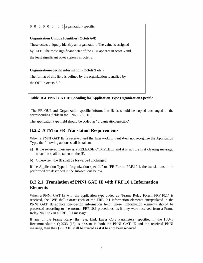
55
0 0 0 0 0 0 0 1 organization-specific
Organization Unique Identifier (Octets 6-8)
These octets uniquely identify an organization. The value is assigned
by IEEE. The most significant octet of the OUI appears in octet 6 and
the least significant octet appears in octet 8.
Organization-specific information (Octets 9 etc.)
The format of this field is defined by the organization identified by
the OUI in octets 6-8.
Table B-4 PNNI GAT IE Encoding for Application Type Organization Specific
The FR OUI and Organization-specific information fields should be copied unchanged to the corresponding fields in the PNNI GAT IE.
The application type field should be coded as “organization-specific”.
B.2.2 ATM to FR Translation Requirements
When a PNNI GAT IE is received and the Interworking Unit does not recognize the Application Type, the following actions shall be taken:
a) If the received message is a RELEASE COMPLETE and it is not the first clearing message, no action shall be taken on the IE.
b) Otherwise, the IE shall be forwarded unchanged.
If the Application Type is “organization-specific” or “FR Forum FRF.10.1, the translations to be performed are described in the sub-sections below.
B.2.2.1 Translation of PNNI GAT IE with FRF.10.1 Information Elements
When a PNNI GAT IE with the application type coded as “Frame Relay Forum FRF.10.1” is received, the IWF shall extract each of the FRF.10.1 information elements encapsulated in the PNNI GAT IE application-specific information field. These information elements should be processed according to the normal FRF.10.1 procedures, as if they were received from a Frame Relay NNI link in a FRF.10.1 message.
If any of the Frame Relay IEs (e.g. Link Layer Core Parameters) specified in the ITU-T Recommendation Q.2933 [18] is present in both the PNNI GAT IE and the received PNNI message, then the Q.2933 IE shall be treated as if it has not been received.

56
B.2.2.2 Translation of PNNI GAT IE with Organization-Specific Information
When a PNNI GAT IE with the application type coded as organization-specific is received, the IWF should translate it to one or two FRF.10.1 GAT information element(s) according to the following procedures:
a) If the length of the PNNI GAT contents (specified in octets 3 and 4) is less than255, then the contents field, starting at octet 5, shall be copied unchanged into the FRF.10.1 GAT IE, starting at octet 4. The “Start” and “End” bits in octet 3 of the FRF.10.1 GAT IE shall both be set to 1 to denote this is a standalone instance, as shown in Figure B-3.
8 7 6 5 4 3 2 1 Octet 8 7 6 5 4 3 2 1 Octet
PNNI GAT information element 1 FRF.10.1 GAT information element 1 1 1 1 0 0 1 0 1 x x x x x x x x 1 Coding IE instruction field 2 Length of GAT contents 2
ext Std Start En Reserved 3
Length of GAT contents 3 1 1 Length of GAT contents (continued) 4 Application Type 4
Application Type 5 5-7 OUI 6-8 OUI
8 9 Organization-specific information :
Organization-specific information : (first 250 octets) : (first 250 octets) : 257
258
Figure B-3 Translation of PNNI GAT IE to Standalone FRF.10.1 GAT IE
b) If the length of the PNNI GAT contents is equal to or greater than 255, then the following
actions shall be taken (as depicted in Figure B-4)
i) The first 254 octets (Application type, OUI and first 250 octets of organization-specific information) of the PNNI GAT IE contents fieldshall be copied unchanged into the first FRF.10.1 GAT IE, starting at octet 4. The “Start” bit in octet 3 shall be coded to 1 and the “End” bit coded to 0 to denote there is another segment to follow.
ii) The remaining octets from the PNNI GAT IE Organization-specific information field (up to a maximum of 254 octets) shall be copied unchanged into the Organization-specific information field of the second FRF.10.1 GAT IE. . The “Start” bit shall be coded to 0 and the “End” bit coded to 1 to denote this is the last segment.
iii) It is mandatory that the GAT instance containing the second segment (with “End” bit coded to 1) be placed immediately after the GAT instance containing the first segment (with Application Type, OUI and “Start” bit coded to 1), in the message to be sent.

57
8 7 6 5 4 3 2 1 Octet 8 7 6 5 4 3 2 1 Octet
PNNI GAT information element 1 FRF.10.1 GAT information element 1 1 1 1 0 0 1 0 1 x x x x x x x x 1 Coding IE instruction field 2 Length of GAT contents 2
ext Std Start End Reserved 3 Length of GAT contents 3 1 0
Length of GAT contents (continued) 4 Application Type 4 Application Type 5 5-7
OUI 6-8 OUI 8 9 organization-specific information :
Organization-specific information : (first 250 octets) : (first 250 octets) : 257
258 259 :
Organization-specific information : 8 7 6 5 4 3 2 1 Octet (remaining 254 octets) 512 FRF.10.1 GAT information element 1
x x x x x x x x Length of GAT contents 2 Start En Reserved 3
0 1 4 Organization-specific information : (remaining 254 octets) : 257
Figure B-4 Segmentation of PNNI GAT IE to Two FRF.10.1 GAT IEs
These procedures will be repeated if there are more than one instance of the PNNI GAT IE in the received message. It is mandatory that all instances of the GAT IE are contiguous.

58
Annex C – ATM Forum PNNI SPVC Addendum Requirements This annex is an optional extension to this implementation agreement. It contains the description and specification for additional SPVC information element translation requirements.
C.1 General Description In the ATM Forum PNNI SPVC Addendum [19], the PNNI 1.0 Calling and Called Soft PVPC/PVCC information elements have been enhanced to signal the DLCI for a Frame Relay endpoint.
This new functionality facilitates the interworking between FR and ATM SVC by providing the following added features:
1. There is a one-to-one direct mapping of the DLCI fields between the two protocols.
2. The FR DLCI value would not be encoded as the ATM VCI in the PNNI SPVC IEs. This will allow the detection of mis-configuration of endpoint types at the destination, which would not be possible using the existing mapping.
3. The restriction for signalling a 16-bit DLCI value is no longer applicable.
4. The PNNI SPVC Addendum procedures has built-in mechanisms to accommodate other endpoint types in the future, without having to upgrade immediate nodes which support this PNNI SPVC Addendum. This will facilitate interworking FR endpoints with endpoint types other than Cell relay, when SPVCs are routed over PNNI networks.
C.2 Additions to FR/ATM SVC Signalling Translations This section defines the additional signalling translations to be performed between the Frame Relay and ATM protocols. FR NNI signalling elements are based on FRF.10.1 [1]. ATM SVC NNI signalling elements are based on the PNNI SPVC Addendum.
C.2.1 FR to ATM Translation Requirements This section specifies the translation requirements in the FR to ATM direction.
C.2.1.1 Called Party SPVC IE Translation
When translating the FRF.10.1 Called Party SPVC IE to the PNNI SPVC Addendum Called Party Soft PVPC/PVCC IE the following actions shall be taken:
1. If the FRF.10.1 Called endpoint selection type indicates “Specific DLCI” or “Assigned DLCI”, the PNNI DLCI fields shall be obtained from the corresponding fields of the FRF.10.1 Called Party SPVC IE. The PNNI Selection type field shall be coded as “Requir“Assigned value” respectively. If no DLCI or a VPI/VCI is included in the FRF.10.1 Called Party SPVC IE, then the call shall be cleared by sending a RELEASE COMPLETE message with cause #100 “Invalid information element contents”.
2. If the FRF.10.1 Called endpoint selection type indicates “ATM endpoint” and the FRF.10.1 ATM called endpoint selection type field indicates “Required value” or “Assigned value”, then the FRF.10.1 ATM called endpoint selection type field shall be mapped directly to the

59
Selection type field contained in the PNNI Called party Soft PVCP/PVCC IE. The PNNI VPCI and/or VPCI/VCI fields shall be obtained from the VPI and/or VPI/VCI fields of the FRF.10.1 called party SPVC IE. If no VPI/VCI or a DLCI is specified in the FRF.10.1 Called Party SPVC IE, the call shall be cleared by sending a RELEASE COMPLETE message with cause #100 “Invalid information element contents”.
3. If the FRF.10.1 Called endpoint selection type indicates “Specific SPVC Correlator” the call shall be cleared with cause #127 “interworking, unspecified”.
C.2.1.2 Calling Party SPVC IE Translation
When translating the FRF.10.1 Calling Party SPVC IE to the PNNI SPVC Addendum Calling Party Soft PVPC/PVCC IE, the PNNI Calling Party Soft PVPC/PVCC IE DLCI or VPCI/VCI fields shall be obtained from the corresponding fields of the FRF.10.1 Calling Party SPVC IE.
C.2.2 ATM to FR Translation
This section specifies the translation requirements in the ATM to FR direction.
C.2.2.1 Called Party SPVC IE Translation
When translating the PNNI SPVC Addendum Called Party Soft PVPC/PVCC IE to the FRF.10.1 Called Party SPVC IE and the PNNI Selection type indicates “Required value” or “Assigned value”, the following actions shall be taken:
1. If the DLCI octet group is included in the PNNI Called Party Soft PVPC/PVCC IE, this is mapped directly to the corresponding fields of the FRF.10.1 Called Party SPVC IE and the FRF.10.1 “Called endpoint selection type” shall be coded as “Specific DLCI” or “Assigned
2. If the VPCI and/or VPCI/VCI octet groups are included in the PNNI Called Party Soft PVPC/PVCC IE, these fields are mapped directly to the VPI and/or VPI/VCI fields of the FRF.10.1 Called Party SPVC IE. The FRF.10.1 “Called endpoint selection type” shall be coded as “ATM endpoint” and the FRF.10.1 “ATM called endpoint selection type” shall be coded as “Required value” or “Assigned value” respectively.
3. If neither the DLCI nor the VPCI/VCI is included in the PNNI Called Party Soft PVPC/PVCC IE, then the call shall be cleared by sending a RELEASE COMPLETE message with cause #100 “Invalid information element contents”.
C.2.2.2 Calling Party SPVC IE Translation
When translating the PNNI SPVC Addendum Calling Party Soft PVPC/PVCC IE to the FRF.10.1 Calling Party SPVC IE, the FRF.10.1 Calling Party SPVC IE DLCI or VPI/VCI fields shall be obtained from the corresponding fields of the PNNI Calling Party Soft PVPC/PVCC IE.