
Network Time Server NTS–100i–GPS · NTSnicAd2a.doc Rev. NC (Applies to manuals for models NIC...
144
Network Time Server NTS–100i–GPS Model NIC-315 455-001 Revision 3 January 10, 2000
Transcript of Network Time Server NTS–100i–GPS · NTSnicAd2a.doc Rev. NC (Applies to manuals for models NIC...

Network Time ServerNTS–100i–GPS
Model NIC-315
455-001Revision 3
January 10, 2000

NTSAdd.doc Rev. N/C
Addendum for Network Time Servers
Rack Mount InstructionsTo securely mount a TrueTime Network Time Server (NTS) in any EIA standard
19 inch rack system*, use the equipment supplied in TrueTime�s Rack Mount Kit
and follow the steps outlined below.
The Rack Mount Kit contains:
• 2 mounting brackets (part number 206-015)
• 4 flat-head, Phillips screws (part number 241-008-005, 8-32 x 5/8)
To rack mount the NTS:
1. Remove the two factory-installed flat head (Phillips) screws from the front end
of the NTS side panel.
2. Place a rack mount bracket on the side panel, so that the countersunk screw
holes in the bracket line up with the screw holes in the panel.
3. Place two of the rack mount screws through the holes in the bracket and into
the NTS.
4. Tighten the screws to the following specifications:
Use a #2 size Phillips bit with an inch ounce torque setting of 4 ¼ to 4 ¾
(high).
5. Repeat steps 1-4 to install the other rack mount bracket on the unit�s other
side panel.
6. Place the NTS in a 1 ¾ inch opening in any EIA Standard 19 inch rack
system, and position the unit so that the rack holes line up with the holes in
the bracket.
7. Use the appropriate screws to secure the brackets to the rack.
8. Ensure that the operating ambient temperature does not exceed +50 °C
(keep ventilation openings clear).
* Installation requires the use of standard rack mount hardware.

NTS�100i�GPS NIC-315
ii January 10, 2000 455-001 Rev. 3
The information in this manual is subject to change without notice and should not be construed asa commitment by TrueTime, Inc. Furthermore, TrueTime, Inc. reserves the right, without notice, tomake changes to equipment design as advances in engineering and manufacturing methodswarrant.
The material described in this manual may be used or copied only in accordance with the terms ofthe license pertaining to the software and hardware referred to herein.
© 1999 TrueTime, Inc.All rights reserved.Printed in the U.S.A.
The following are registered trademarks or trademarks of their relative companies ororganizations: Microsoft, Microsoft Windows, HyperTerminal, and Procomm.

Addendum for TrueTime NTS-100i Network Time Servers
NIC-315 NIC-215 NIC-415
�
Correction to Section 2-2.2 on page 10. The “Apply Power” step should be step #2, not step #5.Apply power after connecting to the synchronization source. Do not wait until the end of this
d
2-2.2 NTP Port/NET Port Network Parameter Configuration
An overview of the network parameter configuration steps are:
1. Make the synchronization connection.
2. Apply power to the NTS.
3. Use serial function 36 (see page”xx”) to enter the IP address, Subnet Mask, and Default Gateway.
NTSnicAd.doc Rev. NC (Applies to manuals for models NIC 205 and 215, NIC 305 and 315, and NIC 405 and 415)
Configure the NTP port and the NET port separately using a serial device that is connected to theavailable RS-232 port at 9600 8N1. Use serial Function F36 to configure the NTP port, and serialFunction F100 to configure the NET port. F36 and F100 use the same parameters; the onlydifference is the function number.
Note: The configuration examples below use one line for all parameters and use letters in thedata fields instead of numbers, to prevent confusion. During your installation, use thenumbers assigned by your System Administrator. You may use a separate line to entereach parameter.
Configure NTP Port network parameters with serial F36, as shown below:
F36 IP:iii.iii.iii.iii SM:sss.sss.sss.sss G:ggg.ggg.ggg.ggg<Enter>
Configure NET Port network parameters with serial F100, as shown below:
F100 IP:jjj.jjj.jjj.jjj SM:lll.lll.lll.lll G:ppp.ppp.ppp.ppp<Enter>
The normal response to the above commands is “OK,” followed by a line terminator. If any otherresponse is received, check the input and re-enter the command.
4. Verify the configuration parameters you entered.
To verify the NTP port network parameters, send the following serial command:
F36<Enter>
Check the returned settings against the ones previously entered. Make any necessary correctionsusing the F36 command.
In a similar way, to verify the NET port settings, send the following serial command:
F100 IC<Enter>
Once the addresses are configured, connect the cables (see the next section for details), thensupply power to the NTS.
5. Connect to the ethernet.

NTSnicAd2a.doc Rev. NC
Addendum for TrueTime NTS-100i Network Time Servers
On Table 1-1, RXNIC should read RXD and TXNIC should read TXD.
Table 1-1: RS-232 Interface Pin Assignments
Pin Assignment
1 NC
2 RXD
3 TXD
4 NC
On Table 3-1, RXNIC sNTS column should saycolumn should be rever
NTS
OPEN
IN RXD
OUT TXD
OPEN
GND
OPEN
OPEN
OPEN
�
Corrections to Table 1-1 in Section 1-12.3 and Table 3-1 in Section 3-5.
NIC-215 NIC-315 NIC-415
5 GND
6 NC
7 NC
8 NC
9 NC
hould read RXD and TXNIC should read TXD; also, the TXD line in the OUT (instead of IN) and the direction of the arrow in the adapter cablesed.
Table 3-1: RS-232 Pinouts and Signal Types
9- to 25-PIN ADAPTER CABLE9-pin 25-pin
RS-232Computer Interface
1 8 DCD, CARRIER DETECT
2– – – – – – <– – – – – – –3 TRANSMITTED DATA
3– – – – – – >– – – – – – –2 RECEIVED DATA
4 20 DTR, DATA TERMINAL READY
�(Applies to manuals for models NIC 215, NIC 315, and NIC 415)
5– – – – – – <>– – – – – – 7 SC, SIGNAL GROUND
6 6 DSR, DATA SET READY
7 4 RTS, REQUEST TO SEND
8 5 CTS, CLEAR TO SEND

NIC-315 NTS�100i�GPS
455-001 Rev. 3 January 10, 2000 iii
Settings of NTS Ethernet Ports
Record NTS-100i network configuration for the NTP and NET ports below, for quick reference.
NET port network setup instructions are detailed in the Quick Start Guide, starting on page 9.
NTP Port Ethernet Address: ____________________________________
NTP Port IP Address: ____________________________________
NTP Port Subnet Mask: ____________________________________
NTP Port Default Gateway: ____________________________________
NET Port Ethernet Address: ____________________________________
NET Port IP Address: ____________________________________
NET Port Subnet Mask: ____________________________________
NET Port Default Gateway: ____________________________________


455-001 Rev. 3 January 10, 2000 v
NTS�100i�GPSTable Of Contents
1 GENERAL INFORMATION........................................................................................ 11-1 INTRODUCTION.....................................................................................................................1
1-1.1 Conventions ................................................................................................................11-1.2 Overview of Internet Access (Telnet and HTTP) ........................................................1
1-2 LIMITED WARRANTY .............................................................................................................21-3 LIMITATION OF LIABILITY.......................................................................................................21-4 PROPRIETARY NOTICE..........................................................................................................21-5 PHYSICAL SPECIFICATIONS...................................................................................................31-6 ENVIRONMENTAL SPECIFICATIONS ........................................................................................31-7 POWER INPUT SPECIFICATIONS ............................................................................................41-8 INTERNAL TIMING PERFORMANCE SPECIFICATIONS................................................................41-9 PROTOCOLS.........................................................................................................................41-10 NETWORK TIME PROTOCOL SYNCHRONIZATION SPECIFICATIONS...........................................51-11 FRONT PANEL INTERFACE ....................................................................................................5
1-11.1 Input: The Keypad and the Push-Buttons...................................................................61-11.2 Output: The Display ....................................................................................................6
1-12 INTERFACE SPECIFICATIONS .................................................................................................61-12.1 NTP Ethernet Interface ...............................................................................................61-12.2 Network Interface Card (NIC) Ethernet Interface........................................................61-12.3 Utility RS-232 I/O Interface .........................................................................................7
1-13 LED STATUS INDICATOR ......................................................................................................71-13.1 Alarm Output...............................................................................................................8
1-14 TIME/FREQUENCY OUTPUT SIGNALS.....................................................................................81-15 SYNC INPUT CHARACTERISTICS ............................................................................................8
2 INSTALLATION......................................................................................................... 92-1 INTRODUCTION.....................................................................................................................92-2 QUICK START GUIDE ............................................................................................................9
2-2.1 Site Preparation ..........................................................................................................92-2.2 NTP Port/NET Port Network Parameter Configuration.............................................102-2.3 Cabling......................................................................................................................112-2.4 Antenna Placement...................................................................................................122-2.5 Verify Functionality....................................................................................................132-2.6 Wrap-up & Advanced Operation...............................................................................13
3 REMOTE OPERATION AND KEYPAD FUNCTIONS.............................................. 153-1 INTRODUCTION...................................................................................................................153-2 NETWORK INTERFACE ........................................................................................................153-3 WEB ACCESS ....................................................................................................................15
3-3.1 Starting the Web Browser.........................................................................................163-4 TELNET ACCESS ................................................................................................................17

NTS�100i�GPS NIC-315
vi January 10, 2000 455-001 Rev. 3
3-4.1 Starting Telnet and Making a Connection.................................................................183-4.2 Ending Telnet............................................................................................................19
3-5 SERIAL ACCESS THROUGH THE UTILITY PORT .....................................................................193-5.1 Serial Line Settings ...................................................................................................203-5.2 Procomm...................................................................................................................203-5.3 HyperTerminal ..........................................................................................................20
3-6 SESSION TIMERS................................................................................................................243-6.1 Utility Port Session Timer..........................................................................................243-6.2 Telnet Session Timer ................................................................................................243-6.3 Web Control Session Timer ......................................................................................25
3-7 NTS START-UP .................................................................................................................253-7.1 Satellite Acquisition...................................................................................................26
3-8 OPERATING MODES ...........................................................................................................263-8.1 Auto Mode.................................................................................................................263-8.2 Survey Mode.............................................................................................................283-8.3 Time Mode ................................................................................................................28
3-9 TIME QUALITY INDICATION ..................................................................................................283-10 FRONT PANEL INTERFACE...................................................................................................29
3-10.1 Alphanumeric Display ...............................................................................................293-10.2 TIME Push-Button.....................................................................................................293-10.3 STATUS Push-Button ...............................................................................................293-10.4 POSITION Push-Button ............................................................................................29
3-11 KEYPAD OPERATION ..........................................................................................................303-12 SELECTING FUNCTIONS AND ENTERING DATA .....................................................................303-13 KEYPAD FUNCTION DESCRIPTIONS......................................................................................32
3-13.1 Keypad Function 00 � Keypad Help Function.........................................................323-13.2 Keypad Function 01 � Time Zone Entry/Request ...................................................323-13.3 Keypad Function 02 � 12/24 Hour Format Request ...............................................333-13.4 Keypad Function 03 � Time and Date Entry/Request.............................................333-13.5 Keypad Function 05 � Time Quality Enable/Setup .................................................343-13.6 Keypad Function 06 � Keypad Lock Enable ...........................................................363-13.7 Keypad Function 13 � Worst-Case Time Error Request ........................................363-13.8 Keypad Function 18 � Software Version Request ..................................................373-13.9 Keypad Function 36 � NTP Port Network Configuration Entry/Request.................37
3-13.9.1 Ethernet Address...........................................................................................................383-13.9.2 IP Address .....................................................................................................................383-13.9.3 Subnet Mask..................................................................................................................383-13.9.4 Default Gateway ............................................................................................................383-13.9.5 Network Type.................................................................................................................393-13.9.6 Clock Type.....................................................................................................................393-13.9.7 MD5 Authentication .......................................................................................................39
3-13.10 Keypad Function 50 � Position Entry/Request....................................................393-13.11 Keypad Function 51 � Antenna Cable Delay Entry/Request...............................403-13.12 Keypad Function 53 � Operating Mode Entry/Request.......................................413-13.13 Keypad Function 55 � Altitude Units Entry/Request ...........................................413-13.14 Keypad Function 56 � Average Position Entry/Request .....................................42

NIC-315 NTS�100i�GPS
455-001 Rev. 3 January 10, 2000 vii
3-13.15 Keypad Function 60 � Satellite List Request.......................................................433-13.16 Keypad Function 65 � Satellite Select.................................................................443-13.17 Keypad Function 66 � Daylight Savings Enable .................................................443-13.18 Keypad Function 67 � Leap Second Information ................................................463-13.19 Keypad Function 68 � Year Entry (GPS Epoch Management) ...........................463-13.20 Keypad Function 71 � Oscillator Statistics Request ...........................................473-13.21 Keypad Function 72 � Fault Status .....................................................................483-13.22 Keypad Function 73 � Display/Set Alarm Status/Control ....................................493-13.23 Keypad Function 79 � Warm Restart ..................................................................52
4 SERIAL OR TELNET I/O FUNCTIONS ................................................................... 534-1 I/O FUNCTION ....................................................................................................................534-2 GENERAL INPUT AND OUTPUT FORMAT...............................................................................55
4-2.1 Exclusive Use ...........................................................................................................564-3 I/O FUNCTION DESCRIPTIONS.............................................................................................56
4-3.1 I/O Function F01 � Time Zone Entry/Request ........................................................564-3.2 I/O Function F02 � 12/24 Hour Format Entry/Request ...........................................574-3.3 I/O Function F03 � Time and Date Entry/Request..................................................584-3.4 I/O Function F05 � Time Quality Enable/Setup ......................................................594-3.5 I/O Function F06 � Keypad Lock Enable ................................................................604-3.6 I/O Function F13 � Worst-Case Time Error Request .............................................604-3.7 I/O Function F15 � Exclusive Use Enable/Disable .................................................614-3.8 I/O Function F18 � Software Version Request .......................................................624-3.9 I/O Function F36 � NTP Port Network Configuration Entry/Request......................62
4-3.9.1 Ethernet Address............................................................................................................... 634-3.9.2 IP Address......................................................................................................................... 634-3.9.3 Subnet Mask ..................................................................................................................... 634-3.9.4 Default Gateway................................................................................................................ 644-3.9.5 Network Type .................................................................................................................... 644-3.9.6 Complete NTP Network Configuration .............................................................................. 644-3.9.7 Clock Type ........................................................................................................................ 654-3.9.8 MD5 Authentication ........................................................................................................... 65
4-3.10 I/O Function F50 – Position Entry/Request ............................................................664-3.11 I/O Function F51 � Antenna Cable Delay Entry/Request .......................................674-3.12 I/O Function F53 � Operating Mode Entry/Request ...............................................684-3.13 I/O Function F55 � Altitude Units Entry/Request ....................................................684-3.14 I/O Function F56 � Average Position Entry/Request ..............................................694-3.15 I/O Function F60 � Satellite List Request ...............................................................714-3.16 I/O Function F65 � Satellite Select .........................................................................724-3.17 I/O Function F66 � Daylight Savings Enable ..........................................................734-3.18 I/O Function F67 � Leap Second Information.........................................................744-3.19 I/O Function F68 � Year Entry (GPS Epoch Management) ....................................754-3.20 I/O Function F71 � Oscillator Statistics Request ....................................................764-3.21 I/O Function F72 � Fault Status ..............................................................................774-3.22 I/O Function F73 � Request/Set Alarm Status/Control ...........................................774-3.23 I/O Function F79 � Warm Restart...........................................................................824-3.24 Extended F100 Commands ......................................................................................83

NTS�100i�GPS NIC-315
viii January 10, 2000 455-001 Rev. 3
4-3.24.1 F100 BASET � 10BASE-T/100BASE-T Control ..........................................................834-3.24.2 F100 DHCP � DHCP Control.......................................................................................844-3.24.3 F100 EA � Ethernet Address.......................................................................................854-3.24.4 F100 G � Gateway.......................................................................................................854-3.24.5 F100 IC � NET Port Network Configuration Request ..................................................864-3.24.6 F100 IP � IP Address ..................................................................................................864-3.24.7 F100 P � Change User Password ...............................................................................874-3.24.8 F100 SM � Subnet Mask .............................................................................................874-3.24.9 F100 ST � Self Test Status..........................................................................................884-3.24.10 F100 VER � Version Request .....................................................................................89
4-3.25 Login/Logout .............................................................................................................894-4 OUTPUTS...........................................................................................................................90
4-4.1 1 PPS Output ............................................................................................................904-4.2 IRIG-B Output ...........................................................................................................90
5 NTS-GENERATED MESSAGES..............................................................................915-1 ERROR MESSAGES.............................................................................................................91
5-1.1 ERROR: Access denied...........................................................................................915-1.2 ERROR: Command is NOT supported ....................................................................915-1.3 ERROR: Login refused ............................................................................................915-1.4 ERROR: Undefined Command ................................................................................915-1.5 ERROR: Exclusive Use ............................................................................................925-1.6 ERROR 01 VALUE OUT OF RANGE.......................................................................925-1.7 ERROR 02 SYNTAX.................................................................................................925-1.8 ERROR 05 No Such Function ..................................................................................92
5-2 INFORMATIONAL MESSAGES ...............................................................................................925-2.1 DHCP is enabled ......................................................................................................925-2.2 DHCP is disabled......................................................................................................925-2.3 Goodbye. ..................................................................................................................925-2.4 Rev Level is ..............................................................................................................925-2.5 Restarting..................................................................................................................93
5-3 NOTICE MESSAGES............................................................................................................935-4 OTHER MESSAGES.............................................................................................................94
5-4.1 OK.............................................................................................................................945-4.2 User Login Message .................................................................................................94
5-5 PASSWORD RELATED MESSAGES .......................................................................................955-5.1 Login: ........................................................................................................................955-5.2 Password: .................................................................................................................955-5.3 Enter new user password: ........................................................................................955-5.4 Enter it again:............................................................................................................955-5.5 ERROR: Passwords do NOT match. New password rejected. ...............................95

NIC-315 NTS�100i�GPS
455-001 Rev. 3 January 10, 2000 ix
APPENDICES
A NETWORK TIME PROTOCOL V 3.0 DATA FORMATS........................................A-1
A-1 INTRODUCTION................................................................................................................. A-1A-2 NTP V 3.0 DATA FORMAT PER RFC-1305 ....................................................................... A-1
A-2.1 NTP Data Packet .................................................................................................... A-1A-2.2 Leap Indicator ......................................................................................................... A-2A-2.3 Version Number ...................................................................................................... A-2A-2.4 Mode ....................................................................................................................... A-2A-2.5 Stratum ...................................................................................................................A-2A-2.6 Poll Interval .............................................................................................................A-2A-2.7 Precision .................................................................................................................A-2A-2.8 Synchronizing Distance (Root Delay Version 3) ..................................................... A-3A-2.9 Synchronizing Dispersion (Root Dispersion Version 3) .......................................... A-3A-2.10 Reference Clock Identifier....................................................................................... A-3A-2.11 Reference Timestamp............................................................................................. A-3A-2.12 Originate Timestamp............................................................................................... A-3A-2.13 Receive Timestamp ................................................................................................ A-4A-2.14 Transmit Timestamp ............................................................................................... A-4A-2.15 Authenticator........................................................................................................... A-4
A-3 SNTP V 3.0 DATA FORMAT PER RFC-1361...................................................................... A-4A-3.1 Leap Indicator ......................................................................................................... A-4A-3.2 Version Number ...................................................................................................... A-4A-3.3 Reference Timestamp............................................................................................. A-4A-3.4 Receive Timestamp ................................................................................................ A-4A-3.5 Transmit Timestamp ............................................................................................... A-4A-3.6 Authenticator........................................................................................................... A-4
B TIME PROTOCOL PER RFC-868......................................................................... B-1B-1 INTRODUCTION................................................................................................................. B-1B-2 THE TIME FORMAT ........................................................................................................... B-1
C IRIG-B TIME CODE ............................................................................................. C-1
C-1 INTRODUCTION.................................................................................................................C-1C-2 IRIG-B CODE FORMAT.....................................................................................................C-1C-3 EMBEDDED WORST-CASE TIME ERROR FLAGS .................................................................C-2
D MD5 AUTHENTICATION PROTOCOL FOR NTP PACKETS............................... D-1D-1 INTRODUCTION.................................................................................................................D-1D-2 TRUETIME NTP MD5 OPERATION ....................................................................................D-2D-3 NTP MD5 KEY MAINTENANCE USING THE KEYPAD INTERFACE .........................................D-2D-4 NTP MD5 KEY MAINTENANCE USING THE TRUETIME SERIAL OR TELNET INTERFACE ........D-4

NTS�100i�GPS NIC-315
x January 10, 2000 455-001 Rev. 3
E SNMP � SIMPLE NETWORK MANAGEMENT PROTOCOL ................................ E-1
E-1 INTRODUCTION.................................................................................................................E-1E-2 TRUETIME SNMP CONFIGURATION ..................................................................................E-1E-3 KEYPAD CONFIGURATION .................................................................................................E-4E-4 SERIAL OR TELNET CONFIGURATION .................................................................................E-5
E-4.1 Read SNMP Configuration......................................................................................E-6E-4.2 Write SNMP Configuration......................................................................................E-7E-4.3 SNMP Global Enable Traps....................................................................................E-8
E-5 TRUETIME SNMP ENTERPRISE MIB.................................................................................E-9E-5.1 Introduction .............................................................................................................E-9E-5.2 Variable Definitions ...............................................................................................E-10
F NON-STANDARD FEATURES .............................................................................. F-1
INDEX

455-001 Rev. 3 January 10, 2000 1
1General Information
1-1 INTRODUCTION
This manual provides you with all of the information necessary to properly install and operate theNTS�100i�GPS Network Time Server (hereafter referred to as the NTS). The information in thismanual includes any normal maintenance and adjustment data that may be required to facilitatefield repairs.
1-1.1 Conventions
The conventions used in this manual are:
Note = Tips and clarifications.
Caution = Actions to prevent equipment damage.
< > = Keyboard entries. For example, <Enter> means press the Enter key for aline terminator; <SP> means press the spacebar to enter a space.
1-1.2 Overview of Internet Access (Telnet and HTTP)
The NTS provides Internet Protocol (IP) network time synchronization over Ethernet connectednetworks via the Network Time Protocol (NTP) developed by Dr. David Mills at the University ofDelaware. In providing this synchronization, the NTS operates as a �server�. The NTS currentlysupports versions 2 and 3.0 of the NTP, RFC-1305, as well as the Simple Network Time Protocol(SNTP), RFC-1361. In addition, the NTS responds to TIME protocol requests, RFC-868. Fordetails about these protocols, refer to Appendix A and Appendix B in this manual). You can obtainthese protocols at web sites listed in Appendix E (Section E-1).
The NTS also provides Internet access to control functions through use of either the Telnetprotocol or the Hypertext Transfer Protocol (HTTP). Telnet is a session-based terminal/remotehost protocol developed for the Internet. Telnet control of an NTS uses the same function stringsthat are employed when using the unit�s front panel keypad. Telnet applications are available onevery Windows NT, 95, or 98 system and is also widely available on UNIX systems. See Section3-4, starting on page 17. HTTP is the protocol used on the web. It presents a user-friendlygraphical user interface and provides access via any web browser. See Section 3-3, starting onpage 15.
An NTS has two RJ-45 Ethernet connectors. The NTP port connector provides NTP access. TheNET port provides Internet/LAN access.

General Information NTS�100i�GPS NIC-315
2 January 10, 2000 455-001 Rev. 3
A 9-pin D serial connector is also provided for user access, however the serial timestamps are notavailable.
The NTS obtains timing information from the global positioning system (GPS).
In addition to performing the functions of an NTP Server, the NTS provides optional 1 PPS andIRIG-B timing and frequency outputs.
1-2 LIMITED WARRANTY
Each new product manufactured by TrueTime is warranted for defects in material or workmanshipfor a period of one year from date of shipment ("Limited Warranty"). Defects in material orworkmanship found within that period will be replaced or repaired, at TrueTime's option, withoutcharge for material or labor, provided the customer returns the equipment, freight prepaid, to theTrueTime factory under this limited warranty. TrueTime will return the repaired equipment, freightprepaid, to the customer's facility. This one year Limited Warranty does not apply to any softwareor to any product not manufactured by TrueTime.
1-3 LIMITATION OF LIABILITY
By purchasing any product from TrueTime, the Buyer consents to and agrees that the Buyer'ssole and exclusive remedy for any damages or losses incurred by the Buyer, as a result ofTrueTime's breach of its one-year Limited Warranty for defects in materials and workmanship orotherwise in connection with any claim respecting the product, shall be limited to the repair orreplacement of the product or a refund of the sales price of the product.
In no event shall the Buyer be entitled to recover consequential damages or any other damages ofany kind or description whatsoever.
1-4 PROPRIETARY NOTICE
THIS DOCUMENT, WHETHER PATENTABLE OR NON-PATENTABLE SUBJECT MATTER,EMBODIES PROPRIETARY AND CONFIDENTIAL INFORMATION AND IS THE EXCLUSIVEPROPERTY OF TRUETIME, INC. IT MAY NOT BE REPRODUCED, USED OR DISCLOSED TOOTHERS FOR ANY PURPOSE EXCEPT THAT FOR WHICH IT IS LOANED, AND IT SHALL BERETURNED UPON DEMAND.

NIC-315 NTS�100i�GPS General Information
455-001 Rev. 3 January 10, 2000 3
1-5 PHYSICAL SPECIFICATIONS
For rack mounting, the NTS requires a 19� enclosure. Physical specifications of the NTS are:
NTS ChassisSize: 1.75 in. x 17.00 in. x 10.38 in. (4.45 cm. x 43.18 cm. x 26.40 cm.)
Weight: 4.21 lb. max. (1.91 Kg).
Standard AntennaSize: 2.625 in. dia. x 1.5 in. (6.67 cm. dia. x 3.81 cm.)
Weight: .55 lb. (.250 Kg) (including mounting nipple)
Power Regulated: ±5 VDC @ <25 mA
Frequency (L1): 1575.42 MHzCoarse Acquisition (C/A) Code
Optional Down ConverterAntenna Size: 4.4 in. dia. x 2.1 in. (11.17 cm. dia. x 6.85 cm.)
Antenna Weight : 0.60 lb (.272 Kg) (including mounting nipple)
Power Regulated: ±5 VDC @ <25 mA
Antenna Cable (for Standard Antenna)Type: RG-59
Attenuation at 1.575 G should be no more than 10.5 dB per 100feet (Belden 9104 or equivalent)
Length: 50 ft. (available in lengths up to 200 ft.)
Weight: 1.2 lb (.545 Kg)
Antenna Cable (for Down Converter Antenna)Type: RG-58
Length: 50 ft. (available in lengths 150 to 1500 ft.)
Weight: 2.7 lb (1.23 Kg) per 100 ft.
Note: For non-standard antenna types, contact TrueTime for assistance.
1-6 ENVIRONMENTAL SPECIFICATIONS
Environmental specifications of the NTS are:
Operating TemperatureNTS Module: 0 to +50 °C (+32 to +122 °F)
Antenna: �40 to +70 °C (�40 to +158 °F)
Storage TemperatureNTS Module: �40 to +85 °C (�40 to +185 °F)
Antenna: �55 to +85 °C (�67 to +185 °F)
HumidityNTS Module: 95%, non-condensing
Antenna: 100%, condensing

General Information NTS�100i�GPS NIC-315
4 January 10, 2000 455-001 Rev. 3
1-7 POWER INPUT SPECIFICATIONS
Power input specifications of the NTS are:
Power InputVoltage: 95-260 VacFrequency: 47-440 HzPower Consumption: <15W
1-8 INTERNAL TIMING PERFORMANCE SPECIFICATIONS
The absolute time and frequency characteristics of the NTS are essentially those of the inputsynchronization source. The relative synchronization characteristics given here reflect thecapabilities of the NTS to preserve the time and frequency characteristics of its synchronizationsource. Refer to Sections 3-8 on page 26 and 3-9 on page 28 for details concerning the time andfrequency characteristics of the NTS.
The NTS output signal timing and frequency specifications relative to the input synchronizationsource are:
1 PPS Output Accuracy: ±5 µsAmplitude Modulated IRIG-B Output Accuracy: ±10 µs
During a synchronization input outage, following initial synchronization of the NTS to the inputsynchronization source, the timing and frequency outputs from the unit diverge from the input atthe rate of approximately 6 parts in 10-6, if the ambient temperature is maintained within ±3°C.
Note: In order to obtain the specified timing accuracy, the unit should be operated with the coverin place.
1-9 PROTOCOLS
The NTS supports the following protocols:
Telnet RFC-854DATETIME RFC-867TIME RFC-868FTP RFC-959SMI RFC-1155*
SNMP RFC-1157MIB RFC-1212MIB II RFC-1213DHCP RFC-2132NTP ver. 3.0 RFC-1305**SNTP RFC-1361***
* SMI = Structure of Management Information** The NTS does not implement the �authenticator field� of the NTP packet as described
in Appendix C of RFC-1305.***The NTS does not support Broadcast Mode.
Note: TIME and DATETIME are available in both TCP and UDP protocols.
Refer to Appendix A and Appendix B in this manual for details about NTP and SNTP protocols,and Appendix E regarding SNMP and MIB protocols and references to RFC documents.
NIC-315 NTS�100i�GPS General Information
455-001 Rev. 3 January 10, 2000 5
1-10 NETWORK TIME PROTOCOL SYNCHRONIZATION SPECIFICATIONS
The NTS hardware is designed specifically to implement the NTP server function. As such it wascarefully designed to operate with the TrueTime real time operating system to minimize theunknown latencies in timestamping the received and transmitted NTP packets.
The NTP Packet timestamp accuracy specifications are:
Received Timestamp Accuracy: ±10 µs, relative to synchronization sourceTransmitted Timestamp Accuracy: ±10 µs, relative to synchronization source
At these levels of accuracy, the realizable NTP synchronization accuracy of any client isdetermined by the repeatability of the network and client delays, not by the NTP timestampuncertainty.
Note: Time accuracy, distributed via NTP, is ultimately determined by client software, as well asnetwork topology.
1-11 FRONT PANEL INTERFACE
This section provides a general description of the NTS front panel input devices. For details abouthow to enter commands and interpret display readouts, see Section 3-11, starting on page 30.
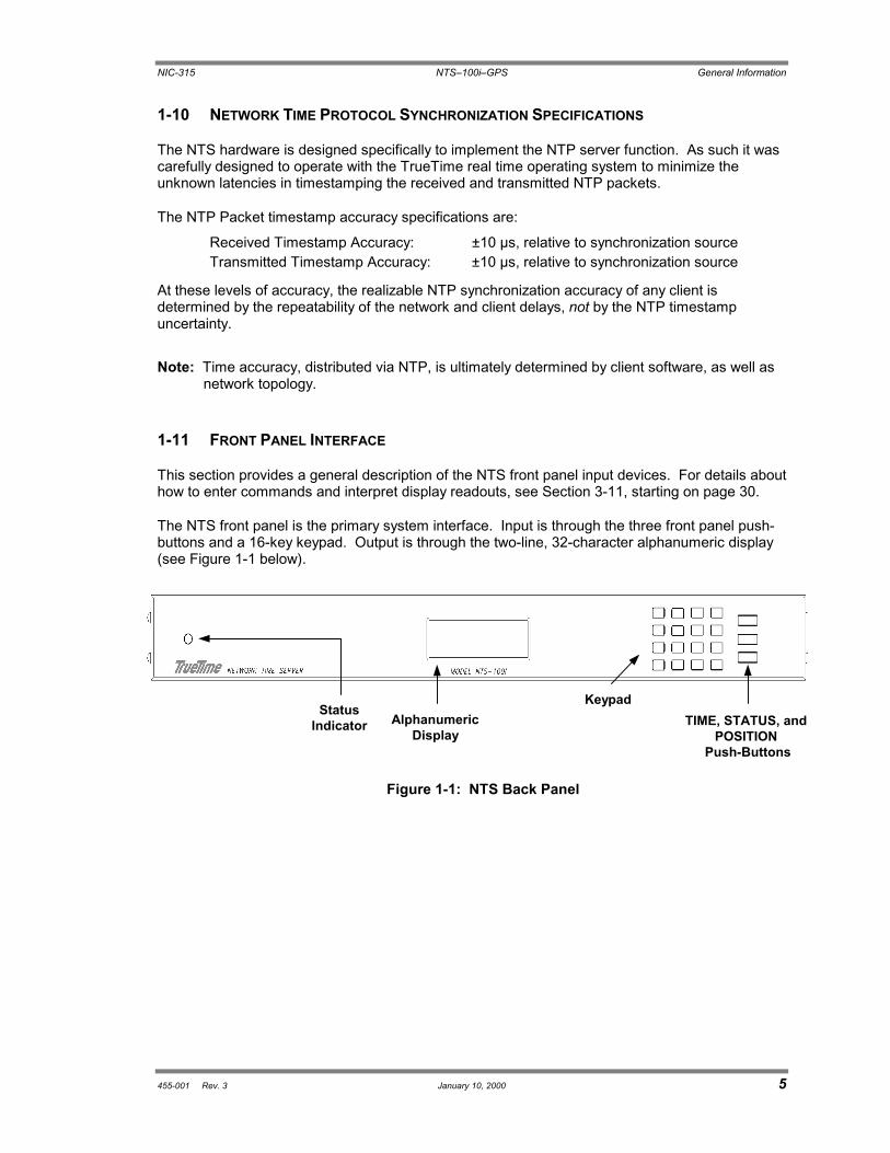
The NTS front panel is the primary system interface. Input is through the three front panel push-buttons and a 16-key keypad. Output is through the two-line, 32-character alphanumeric display(see Figure 1-1 below).
Figure 1-1: NTS Back Panel
AlphanumericDisplay
KeypadTIME, STATUS, and
POSITION Push-Buttons
StatusIndicator

General Information NTS�100i�GPS NIC-315
6 January 10, 2000 455-001 Rev. 3
1-11.1 Input: The Keypad and the Push-Buttons
The keypad consists of numeric keys "0" through "9", arrow keys "up", "down", "right", and "left", aclear key "CLR" and the function/enter key, "FUNC/ENTR". Use the keypad to issue functioncommands and to navigate TrueTime menus. The up- and down-arrow keys scroll through thelist of menu items and FUNC/ENTR actuates the selected menu option (see Section 3-11,starting on page 30, for details).
Pressing the TIME push-button places the equivalent time-of-year and the date on thealphanumeric display. The format of the date is day-of-week, month, day-of-month, year.
Pressing the STATUS push-button displays information indicating whether or not the unit is lockedor unlocked to its synchronization input source. Another use of the STATUS push-button is toabort any keypad function currently in progress. For example, if you enter an incorrect function, orif the display shows something unexpected, pressing the STATUS push-button aborts thefunction, with no action taken by the function.
Pressing the POSITION push-button repeatedly toggles between the latitude, longitude, altitudeand PDOP (Position Dilution of Precision) of the GPS antenna, based on the last position fix. Thevalues are the same as those displayed when requesting information through Function 50(Position Entry/Request).
Note: PDOP represents the degree to which the satellite geometry increases possible errors in aposition fix.
1-11.2 Output: The Display
The front panel display shows current clock status and the system�s response to commands youenter through the keypad. When the display is not being used for keypad function, you can set itto show (in real time) the current clock mode, or the current time with calendar day and year.
1-12 INTERFACE SPECIFICATIONS
1-12.1 NTP Ethernet InterfaceType: 10Base-TFrame Format: DIX Ethernet (Ethernet II) or IEEE 802.3
1-12.2 Network Interface Card (NIC) Ethernet InterfaceType: 10/100Base-TFrame Format: DIX Ethernet (Ethernet II) or IEEE 802.3
Note: The factory-shipped frame format supports the majority of Ethernet-based networks.Check with your System Administrator for more information.

NIC-315 NTS�100i�GPS General Information
455-001 Rev. 3 January 10, 2000 7
1-12.3 Utility RS-232 I/O Interface
Note: Serial timestamps are not available from an NTS.
Data: Serial or Telnet functions (see Chapter 4, starting onpage 53)
Data Rates: 9600Data Bits: 8Parity: NoneStop Bits: 1Connector: Male 9-pin D subminiature, wired as DTE
Note: Serial I/O settings are factory set and cannot be changed. For cabling information and aback panel illustration, see page 11.
The following table shows the RS-232 Interface Pin Assignments:
Table 1-1: RS-232 Interface Pin Assignments
Pin Assignment
1 NC
2 RXNIC
3 TXNIC
4 NC
5 GND
6 NC
7 NC
8 NC
9 NC
1-13 LED STATUS INDICATOR
A front panel mounted, tri-color LED reflects the status of the NTS:
Solid Red: Major Alarm FaultSolid Orange: Minor Alarm FaultBlinking Green: Fully Operational State, no enabled faults are
detected
When the NTS is in either alarm condition, the open collector alarm will be in a high impedancestate. The non-alarm condition corresponds with the open collector alarm output low impedance.
Major Alarm Faults can be caused by antenna loss, GPS receiver failure, or non-volatile RAMdata failure.
Minor Alarm Faults can be caused by reaching the time error threshold, loss of tracking, orreaching the oscillator tuning voltage limit. When the unit is in initial acquisition mode, the LEDalso displays solid orange.

General Information NTS�100i�GPS NIC-315
8 January 10, 2000 455-001 Rev. 3
1-13.1 Alarm Output
The purpose of the alarm output BNC is to provide an indication of an out-of-service conditioncaused by initial power-up, an extended period without synchronization input, or hardware failure.The Leap Indicator bits of the NTP packet sent by the NTS are set to 3, based solely on the timeerror minor fault. The time error threshold is sent in the NTP packet as the root dispersion.
1-14 TIME/FREQUENCY OUTPUT SIGNALS
A combination of two output signals are available from the NTS via panel mounted, female BNCconnectors. The available output signals are:
1-14.1 IRIG-B Time Code:
Format: IRIG-B 122Carrier: 1 KHzAmplitude: 5.0 Vp-p high, 1.5 Vp-p low, no loadOutput Z: 600 ohmsConnector: Female BNC, J1
1-14.2 1 PPS Output:
Amplitude: ACMOS LevelsOutput Z: 22 ohmsConnector: Female BNC, J2
1-15 SYNC INPUT CHARACTERISTICS
Format: GPSInput Characteristics: Antenna

455-001 Rev. 3 January 10, 2000 9
2Installation
2-1 INTRODUCTION
You must provide the NTS with a source of power, a GPS antenna connection, two Ethernetnetwork connections, setup parameters, and any optional output connections (see Appendix F forany optional output connections your device may be equipped with). Once configured, the NTS iscapable of basic operation without an RS-232 connection, and retains all configuration data innon-volatile memory when power is removed.
Of the two Ethernet connections, one is for NTP output (the NTP port), and the other is for theInternet/LAN connection (NET port). The NET port is used to control the NTS from a remotelocation. The network connections are made via the Ethernet RJ-45 connectors that plug in to theoutlets labeled NET port and NTP port.
See Section 2-2.3 on page 11 for an illustration of cable connections.
2-2 QUICK START GUIDE
This quick start guide is designed for both novice and experienced users, and provides theminimum set of instructions required for basic NTS setup.
2-2.1 Site Preparation
To install and use the NTS, you must have access to the following:
� An Ethernet LAN that has two ports available at the NTS location� Two sets of network address parameters, one set for the NTP port that delivers NTP time,
the other set for the NET port that is used to remotely control the unit
Each address set consists of the following:
� IP Address� Subnet Mask� Default Gateway� A serial interface device, either PC or dumb terminal, capable of 9600 8N1� RS-232 cable and null modem connector for the serial connection� Two Ethernet cables with RJ-45 connectors, one for the NTP port and one for the NET
port
Note: The NET port may optionally be configured to use DHCP to obtain its IP Address. TheSystem Administrator will know whether to manually assign the IP Address, or enableDHCP.

Installation NTS�100i�GPS NIC-315
10 January 10, 2000 455-001 Rev. 3
Caution: To ensure proper functioning, perform the installation steps in the order presentedbelow. Configure the NTP and NET ports� IP Address, Subnet Mask, and DefaultGateway before connecting their respective cables.
2-2.2 NTP Port/NET Port Network Parameter Configuration
An overview of the network parameter configuration steps are:
1. Make the synchronization connection by attaching the GPS antenna.2. Use serial function 36 (see page 62) to enter the IP address, Subnet Mask, and Default
Gateway.
Configure the NTP port and the NET port separately using a serial device that is connectedto the available RS-232 port at 9600 8N1. Use serial Function F36 to configure the NTPport, and serial Function F100 to configure the NET port. F36 and F100 use the sameparameters; the only difference is the function number.
Note: The configuration examples below use one line for all parameters and use lettersin the data fields instead of numbers, to prevent confusion. During yourinstallation, use the numbers assigned by your System Administrator. You mayuse a separate line to enter each parameter.
Configure NTP Port network parameters with serial F36, as shown below:
F36 IP:iii.iii.iii.iii SM:sss.sss.sss.sss G:ggg.ggg.ggg.ggg<Enter>
Configure NET Port network parameters with serial F100, as shown below:
F100 IP:jjj.jjj.jjj.jjj SM:lll.lll.lll.lll G:ppp.ppp.ppp.ppp<Enter>
The normal response to the above commands is �OK,� followed by a line terminator. Ifany other response is received, check the input and re-enter the command.
3. Verify the configuration parameters you entered.
To verify the NTP port network parameters, send the following serial command:
F36<Enter>
Check the returned settings against the ones previously entered. Make any necessarycorrections using the F36 command.
In a similar way, to verify the NET port settings, send the following serial command:
F100 IC<Enter>
Once the addresses are configured, connect the cables (see the next section for details),then supply power to the NTS.
4. Connect to the ethernet.5. Apply power to the NTS.

NIC-315 NTS�100i�GPS Installation
455-001 Rev. 3 January 10, 2000 11
2-2.3 Cabling
Refer to Figure 2-1 (NTS Back Panel) for connector locations. The numbers in the drawing referto that connector�s position in Table 2-1 (NTS Cabling).
Note: It is important to connect the cables in the order listed in Table 2-1.
Table 2-1: NTS Cabling
ConnectionOrder Cable Name Required
or Optional Description Type Label
1 Serial Interface Required Utility port adjacent to theNET Port 9-pin D SERIAL I/O
2 Net Interface Required NET Port - for Telnet/Webcontrol of unit RJ-45 NET PORT
3 Sync In Required GPS Antenna BNC SYNC IN
4 NTP Interface Required NTP Port - for NTP output RJ-45 NTP PORT
5 IRIG-B Optional IRIG-B output BNC J1
6 1 PPS Optional One pulse per secondoutput BNC J2
7 Alarm Optional Alarm contact BNC ALARM
8 Chassis Ground Optional Ground screw - (Symbol)
9 Power Required Power socket - VAC INPUT
VAC INPUT(9)
Serial I/O Port(RS-232 Connector for
Serial Connections)(1)
NET Port(RJ-45 for Telnet/Web
User Interface)(2)
NTP Port(RJ-45 for NTPConnections)
(4) J2 (6) J1 (5) SYNC INPUT (3)Chassis Ground
(8)
Alarm (7)
Figure 2-1: NTS Back Panel

Installation NTS�100i�GPS NIC-315
12 January 10, 2000 455-001 Rev. 3
2-2.4 Antenna Placement
2-2.4.1 General Information
The GPS Synchronized Receiver operates on the L1 (1575.42MHz) signal and the C/A code (1.023 MHz bit rate) with aminimum signal level of �162.0 dBW and a maximum signal levelof �137.0 dBW. The system supplied is designed to provide theproper signal levels to the receiver with the cable length supplied.
2-2.4.2 Lead-In Cable
The L1 GPS Antenna is designed to operate with up to 200 feetof RG-59 coax cable. The optional Down Converter is designedto operate with up to 1,500 feet of RG-58 coax cable. Fordetails, see the specifications, starting on page 3.
2-2.4.3 Antenna Installation and Location
When selecting a site for the antenna, find an outdoor locationthat provides full 360-degree visibility of the horizon. In mostcases, this means locating the antenna as high as possible.Any obstruction will degrade unit performance by blocking thesatellite signal or causing a reflection that cancels some of thesignal. Blocked signals can significantly increase the time forsatellite acquisition, or prevent acquisition altogether.
Mounting brackets are provided to mount the antenna to a pole or the peak of a building. Oneof the easiest ways to mount the antenna is with a pipe that has an inside diameter greaterthan one inch. Pass the coaxial cable through the pipe, connect the antenna, then fasten thepipe to a convenient part of the building.
2-2.4.4 Mast Mounting
Mast top mounting is the preferred mounting method. Theantenna mounting mast should be 2-inch threaded water pipe orconduit. The pipe must be rigid and able to withstand high windswithout flexing. Guy wires may be used to stabilize a pipe longerthan 10 feet.
Multipath cancellation is caused by reflected signals that arrive atthe antenna out of phase with the direct signal. Reflectiveinterference is most pronounced at low elevation angles from 10to 20 degrees above the horizon. The height of the mast may beextended to prevent multipath cancellation. The antenna shouldbe at least 1.0 m from a reflecting surface. Figure 2-3 shows therecommended mounting of the antenna to the mast.
Figure 2-2
Basic Antenna Components
Figure 2-3
Basic Antenna Components
Mast
Antenna

NIC-315 NTS�100i�GPS Installation
455-001 Rev. 3 January 10, 2000 13
2-2.5 Verify Functionality
To verify that the unit is running, press the TIME push-button on the front panel, or send the serialF03 command. The time data being generated by the unit is displayed on the front panel, as wellas by the serial F03 return. Also, check the front-panel LED status indicator:
� At power-up, the LED is solid red� While the NTS is acquiring satellites, the LED is solid orange and the Open Collector Alarm
Output is in a high impedance state; if you send the serial F03 command during this time, theNTS displays the time data being generated
� Once the NTS achieves stabilization, the LED is blinking green
To verify functionality of the NTP and NET ports:
1. Ping the NTP port IP Address.
2. Ping the NET port IP Address.
3. If either of these actions fails, or if the LED is not functioning as expected, return toSection 2-2.2 on page 10 to check the configuration values assigned to the ports, andcorrect parameters as necessary.
4. If the NTS is still not operational, verify with your system administrator that the valuesused are correct. Then re-enter parameters as necessary. If problems persist, contactTrueTime Technical Customer Service.
2-2.6 Wrap-up & Advanced Operation
When the LAN interfaces are operational and time is being reported, the unit has achieved itsbasic level of functionality.
Once the NTS has stabilized, indicated by the blinking green LED, clear the latched error flagsusing serial Function 73 (see page 77). This allows you to distinguish between errors thatoccurred during start-up and functional errors that may occur during normal operation.
For details of unit operation, see Chapters 3 and 4. This manual also describes error recoveryprocedures in Chapter 5.
Caution: After the NTS is completely configured, you may remove the RS-232 Utility port serialcable at any time. However, to avoid damaging your equipment, power-down the NTSbefore connecting (or re-connecting) any cable.


455-001 Rev. 3 January 10, 2000 15
3Remote Operation and Keypad Functions
3-1 INTRODUCTION
TrueTime�s NTS is an advanced network time server that provides accurate time over an Ethernetconnection to multiple client sites, and can be monitored and controlled over the Internet or LAN.
The most commonly used NTS functions (TIME and STATUS) are assigned to front-panelpush-buttons (pressing the POSITION push-button has no effect on the unit). You can accessand view all functions in several ways:
Access Viewing Medium
Front-Panel Keypad NTS Front-Panel Alphanumeric Display
Serial I/O Interface PC Terminal
Telnet or Web Interface PC Terminal or other Monitor
In order to remotely configure or monitor the NTS via the web interface or a Telnet session, youmust be able to establish a connection to the NTS using a computer (portable, desktop, orworkstation) attached to a TCP/IP-based Ethernet network. If the NTS is located behind afirewall, or in an isolated LAN or subnet, a connection may not be possible. Check with your localLAN administrator or IT manager for assistance with your computer, network connection, orsoftware.
3-2 NETWORK INTERFACE
The NTS supports protocols RFC-868, RFC-1305 and RFC-1361. An NTP or SNTP client,compatible with the computer platform you use, is required for accurate network synchronization.The client must be configured to use the NTS NTP port IP address. In addition, the NTS supportsSNMP MIB II and Enterprise MIB. See Appendix E for details on SNMP implementation.
3-3 WEB ACCESS
The main feature of the NTS web interface is its ability to perform setup and control operationsfrom a remote location, using the Internet or TCP/IP LAN. The protocol used for Internet accessto an NTS is either Telnet or HTTP. Telnet is a standard Internet communications program that isbundled with Windows 95/98/NT and connects to the NTS through its NET port. HTTP access isprovided via any standard Web Browser (such as Microsoft�s Internet Explorer or Netscape�sNavigator/Communicator).
Remote Operation and Keypad Functions NTS�100i�GPS NIC-315
16 January 10, 2000 455-001 Rev. 3
3-3.1 Starting the Web Browser
To use the web interface, launch any Java-capable and frames-compatible web browser such asMicrosoft Internet Explorer (IE version 3.0 or later, available at www.microsoft.com), NetscapeNavigator (version 3.0 or later) or Netscape Communicator (any version; Netscape browsers areavailable at www.netscape.com).
3-3.1.1 Accessing the NTS Web Interface
In the "Location:" field (Netscape), the "Address:" field (Internet Explorer), or the equivalentfield in the window of a different web browser, enter the IP address assigned to the NET portof the NTS in the following format:
http://<ipaddress>
An example of an NTS NET port IP address is: http://192.168.1.1
The available web pages are: Home, Time, GPS, Satellite Status, Network Status, andControls. When entering from the IP address, your first stop is the Home Page.
3-3.1.2 Home Page
After entering the NET port IP address, TrueTime�s home page appears in the browserwindow. You can access all the other web pages from the home page, so for future quickaccess, bookmark it (in Netscape) or add it to your browser favorites (in Internet Explorer).
3-3.1.3 Time, GPS, Satellite Status, and Network Status Pages
These pages display status. You can navigate from page to page using the correspondingbuttons at the top of the web browser window.
Note: The button for access to the Satellite Status page is located on the GPS Status page.
The values displayed on these pages are static, i.e., they may not reflect changes thatoccurred following the initial display of the page. An example of this is current LocalInstrument Time field on the Time Status page. The time shown is the time read at the instantthe web page first displayed, and does not update with the most recent values until you clickthe Reload or Refresh button of your web browser.
3-3.1.4 Configuration Control Login Page
Enter the NTS control portion of the site through the control login page. To get there, click theControls button located at the top any of the status pages.
The user name is operator and the default password is mercury. Enter these values (alllower case and not bold) in the corresponding fields on this page, then click the Press toContinue button. The page refreshes and the Status Message window indicates whether ornot the login passed (you may have to scroll down to see it). See page 89 for Login/Logoutdetails.
Note: As with all password protection, to ensure security please change the default passwordas soon as possible using the "F100 P" command (see page 87). Password changecan only be made using the serial or Telnet interface.

NIC-315 NTS�100i�GPS Remote Operation and Keypad Functions
455-001 Rev. 3 January 10, 2000 17
3-3.1.5 Time and Network Control Pages
The Time, GPS, Satellite, and Network control pages allow for remote control of the NTS.Navigate from page to page using the corresponding buttons located at the top of each page.
The values displayed on these pages are static, i.e., they may not reflect changes thatoccurred following the initial display of the page. An example of this is the current LocalInstrument Time field on the Time Control page. The time shown is the time read at theinstant the web page first displayed, and does not update with the most recent values until youclick the Reload or Refresh button of your web browser.
To make a change to a value, either enter the new values, or chose the appropriate valuesfrom either the radio buttons or drop-down lists, and click the Submit Changes button,located near the bottom of each control page. The changes are submitted to the NTS and thepage refreshes, showing the new values. Check the Status Message Window locatedimmediately below the Submit Changes button. Occasionally, a change to a parameter failsdue to a processing error or transient network problem. If this occurs, simply resubmit thechanges. If you encounter repeated failures, use the Telnet or serial interfaces to affect therequired changes.
3-3.1.6 Leaving the Control Interface
The control session, activated with a successful login, ends under the followingcircumstances:
� Inactivity: no page navigation or submission of changes in the last five minutes� Location change: navigation to a status page or the home page
If inadvertently logged out, navigate to the Control Login page (click the Controls button) fromthe home page or any status page, then follow the guidelines in Section 3-3.1.4 above.
3-3.1.7 Leaving the Web Interface
To terminate the web interface, exit your web browser or enter a new URL.
3-4 TELNET ACCESS
The NTS can perform setup and control operations sent from a remote location through theInternet. The protocol used for Internet access to an NTS is Telnet, a standard Internetcommunications program, with an ASCII character-based interface, that is bundled with Windows95/98/NT and connects to the NTS through its NET port. Use Telnet just like Procomm, or anyother serial interface program, by entering F-series commands, to which the NTS responds.
Note: Check with your System Administrator for Telnet application information, if you are usingan operating system other than Windows (such as Macintosh or UNIX).
Telnet can only send in commands when there is no active session on the Utility port. If a Utilityport session is active, either Telnet login will fail or, if already logged in, any Telnet commandgenerates the response:
NOTICE: Cannot respond to command because Utility Port session has priority.

Remote Operation and Keypad Functions NTS�100i�GPS NIC-315
18 January 10, 2000 455-001 Rev. 3
3-4.1 Starting Telnet and Making a Connection
1. Press the Start button at the lower left of your screen.
2. Click Run and enter �Telnet� in the Open field.The Run dialog box appears:
3. Click OK.The Telnet � (None) window appears:
4. Click Connect, the first item on the Telnet menu bar, then select Remote System.The Connect dialog box appears:
5. In the Host Name field, enter the IP Address of the NTS.Do not change the text in the other two fields, which should read �Telnet� and �VT100�.
6. Click Connect to start a Telnet connection to the NTS.If the connection was successful, a login prompt appears:
If an hourglass appears instead, it means the connection was not successful and youshould repeat steps 1-5.
7. Enter the login name �guest�.A password prompt appears.

NIC-315 NTS�100i�GPS Remote Operation and Keypad Functions
455-001 Rev. 3 January 10, 2000 19
8. Enter the default password �truetime� (one word, all lower case).A welcome message appears if the login and password are approved:
9. Begin your Telnet session by entering F-series commands.
3-4.2 Ending Telnet
There are two ways to end Telnet:
� Close it from your terminal by selecting Exit from the Connect menu
� Let it timeout; if no commands are received for 15 minutes, the NTS automaticallyterminates the session
3-5 SERIAL ACCESS THROUGH THE UTILITY PORT
With the exception of serial timestamp-related functions (which are not supported on the NTS),this RS-232 connector provides serial access. The RS-232 connector is located to the left of theNET port connector on the back of the NTS (see Figure 2-1 on page 11). This connector islabeled �Serial I/O�, and is referred to as the �Utility port.�
Note: Serial time output is not available on the Utility port.
The following table describes the Utility port�s RS-232 pinouts and signal types, using a nullmodem cable:
Table 3-1: RS-232 Pinouts and Signal Types
NTS 9- to 25-PIN ADAPTER CABLE9-pin 25-pin
RS-232Computer Interface
OPEN 1 8 DCD, CARRIER DETECT
IN RXNIC 2� � � � � � <� � � � � � �3 TRANSMITTED DATA
IN TXNIC 3� � � � � � <� � � � � � �2 RECEIVED DATA
OPEN 4 20 DTR, DATA TERMINAL READY
GND 5� � � � � � <>� � � � � � 7 SC, SIGNAL GROUND
OPEN 6 6 DSR, DATA SET READY
OPEN 7 4 RTS, REQUEST TO SEND
OPEN 8 5 CTS, CLEAR TO SEND
OPEN 9 22 RI, RING INDICATOR

Remote Operation and Keypad Functions NTS�100i�GPS NIC-315
20 January 10, 2000 455-001 Rev. 3
3-5.1 Serial Line Settings
Serial I/O settings are factory set and cannot be changed. The default serial format is:
Data Rate: 9600 bits/secondWord Length: 8 bitsParity: NoneStop Bits: 1
To connect to a computer�s serial port, use a null modem. Any serial access program may beused to connect to the Utility port. All commands are input using conventional TrueTime F-seriestype commands (see Chapter 4, starting on page 53). For cabling information and a back panelillustration, see page 11.
Note: The following examples use two popular Windows-based serial programs, Procomm andHyperTerminal. These examples apply only to systems using Windows 95/98/NT. Checkwith your System Administrator if you are using another operating system.
The Utility port can be connected to a terminal or a computer. These instructions assume that aterminal is connected.
Note: When using Procomm or HyperTerminal, start the program before using the serial cable toconnect the computer to the NTS.
3-5.2 Procomm
As with all TrueTime products, connect the serial cable from the computer running Procomm tothe NTS Utility port.
3-5.3 HyperTerminal
To use HyperTerminal, follow the steps described in the following sections.
3-5.3.1 Starting HyperTerminal
To start HyperTerminal:
1. Click the Start button on the task bar.
2. Select Programs > Accessories > HyperTerminal > HyperTerminal.The Connection Description dialog box appears:

NIC-315 NTS�100i�GPS Remote Operation and Keypad Functions
455-001 Rev. 3 January 10, 2000 21
3. Enter a name (such as �NTS�) for this connection in the Name box and click OK.The Connect To dialog box appears:
4. In the Connect using box, use the drop-down menu to select your modem�s Com port(COM1 in this example), then click OK.The COM1 Properties dialog box appears, showing the Port Settings tab:
5. Edit the fields in the Port Settings dialog box as follows:
Bits per second 9600Data bits 8Parity NoneStop Bits 1Flow control None
6. Click OK.The NTS HyperTerminal window appears, indicating the NTS is now connectedthrough the Utility port:

Remote Operation and Keypad Functions NTS�100i�GPS NIC-315
22 January 10, 2000 455-001 Rev. 3
3-5.3.2 Setting Up a HyperTerminal Session
To set up a HyperTerminal session:
1. From the File menu in the session window, select Properties.The NTS Properties dialog box appears, showing the Connect To tab:
2. Select the Settings tab and click the Terminal keys radio button.
3. In the Emulation box, use the drop-down menu to select VT100 terminal type (do notselect the Auto detect option).

NIC-315 NTS�100i�GPS Remote Operation and Keypad Functions
455-001 Rev. 3 January 10, 2000 23
4. Click Terminal Setup and configure the terminal by selecting the appropriate optionsin the Terminal Settings dialog box (with a VT100 terminal, the recommendedsettings are pictured below):
5. Click ASCII Setup�The ASCII Setup dialog box appears:
6. Place check marks in the following boxes:
� Send line end with line feeds� Echo typed characters locally� Wrap lines that exceed terminal width
7. Click OK.This returns you to the NTS Properties dialog box.
8. Click OK.This returns you to your HyperTerminal session window, where you can enter�F� sequence commands.

Remote Operation and Keypad Functions NTS�100i�GPS NIC-315
24 January 10, 2000 455-001 Rev. 3
9. When exiting HyperTerminal, click Yes when prompted to save the current session:
The next time you launch HyperTerminal from the Start menu, you can reconnect to thesession you just created.
3-5.3.3 To reconnect to your last HyperTerminal session:
1. From the HyperTerminal window, select File > Open.
2. Double-click your last session:
3-6 SESSION TIMERS
There are timers on Utility port and Telnet sessions that terminate them, if there is a lack ofactivity. Any action you take during a session resets the timer, and it starts all over again. Thetimers and their interactions are described in the following sections.
3-6.1 Utility Port Session Timer
The Utility port Session Timer starts upon receipt of a character from the Utility port. The timer isreset upon receipt of every character. If no characters are received for fifteen consecutiveminutes, the Utility port Watchdog Program terminates the session.
When a Utility port session is in progress, Telnet cannot execute any commands to the NTS. TheUtility Port session must end before full Telnet access is possible.
3-6.2 Telnet Session Timer
The Telnet Session Timer starts upon receipt of a command line from Telnet, via the NET port.The timer is reset upon receipt of every command line. If no lines are received for fifteenconsecutive minutes, the Telnet port Watchdog Program terminates the session.
Terminating a Telnet session drops the connection to the remote host. You can immediatelyactivate a new session by logging in again.
The name of your last session

NIC-315 NTS�100i�GPS Remote Operation and Keypad Functions
455-001 Rev. 3 January 10, 2000 25
3-6.3 Web Control Session Timer
The Web Control Session Timer starts upon receipt of an HTTP request from a web browser, viathe NET port. The timer is reset upon receipt of every HTTP request. If no HTTP requests arereceived for five consecutive minutes, the Web Control Watchdog program terminates the session.
Terminating a Web Control session causes the NTS to deny any further requests you make forchanges. You can immediately activate a new session by logging in again.
3-7 NTS START-UP
At power-up, the NTS checks its EEPROM for valid configuration data. If configuration data is validand present, then the NTS attempts to synchronize its internal time to the synchronization source.
Once the NTS has synchronized itself, then it is ready to respond to any requests that it receivesover the serial connection. During interruptions of the synchronization input, the NTS estimatesthe quality of the time it is able to provide to clients and updates the fields of the NTP packetappropriately. In addition, the time quality character of the �worst-case time error,� reported byFunction 13, is also updated during such interruptions. The NTS provides NTP server operationuntil the �worst case time error� has exceeded the value of the root dispersion field set in the NTPpacket. See Section 3-9 (Time Quality Indication) on page 28, and Appendix A, for details on thisbehavior. For details about start-up procedures, see the Quick Start Guide, starting on page 9.
Note: An NTS does not, at any time, output continuous elapsed time to the serial port.
Messages on the front panel display indicate which version of software is installed, and how touse the keypad help function.
The first message is the version of the system software. An example of the response is:TRUETIME MKIIIsys ver 007
After a few seconds, the display shows:Press func, 0, 0for help.
Then the display shows the version of the clock-specific software:NTS V1.007
An example of the response is:182-7004v001
Note: The text of the version messages varies from model to model and version to version.
After a few seconds, the display shows the STATUS display, which remains until a keypadfunction is invoked, or the TIME or POSITION push-button is pressed.

Remote Operation and Keypad Functions NTS�100i�GPS NIC-315
26 January 10, 2000 455-001 Rev. 3
3-7.1 Satellite Acquisition
Satellite acquisition begins at power-up and continues until power-down. Time to first satelliteacquisition depends on many factors. The following paragraphs describe some of the possibleevents that affect satellite acquisition times.
Note: Satellite visibility at the receiver antenna site affects time to first satellite acquisition.
The NTS attempts to acquire satellites, not knowing which satellites are visible. Its searchcontinues until a satellite is acquired. If the position of the GPS antenna is already known, time isacquired from the first satellite and the receiver returns to normal operation. This procedure maytake from as little as 3 minutes to as long as 15 minutes, depending upon current satellite visibility.
If the current GPS antenna position is unknown, or in error by more than 100 Km (62 miles),acquisition typically requires from 3 to 15 additional minutes to locate current antenna position,reacquire satellite almanac and ephemeris data, and deliver UTC time. Refer to AUTO MODEbelow for operational details.
If the NTS has saved a good current average position In AUTO or TIME mode, and has savedrecent UTC leap second information, it typically locks to GPS in 3 to 5 minutes and delivers UTCtime.
3-8 OPERATING MODES
The NTS operates under one of three modes: AUTO, SURVEY and TIME. Each mode isdescribed below.
Use Function 53 (see page 41), or serial Function F53 (see page 68) to change from one mode toanother or to determine the current mode.
The out-of-the-box default mode is AUTO. The default on subsequent power-up will be the modeused at the previous power-down, unless the unit is moved more than 1km, in which case itreverts to AUTO mode.
3-8.1 Auto Mode
AUTO mode offers a painless solution to GPS receiver installation, start-up and operation. UnderAUTO mode, no user input is required to properly complete an NTS site installation, however aminimum of 4 satellites is required to complete the installation process.
Note: Invoking AUTO mode clears the average position and may disturb the time and frequencyoutputs. For this reason, do not unnecessarily use AUTO mode.
After unit installation, or whenever you reinstall the NTS, select AUTO MODE using keypadFunction 53, or serial or Telnet function 53.
AUTO mode consists of 3 phases:
Phase 1: Current Position SearchPhase 2: Current Position Averaging and RefinementPhase 3: Invocation of Time Mode

NIC-315 NTS�100i�GPS Remote Operation and Keypad Functions
455-001 Rev. 3 January 10, 2000 27
Time and Frequency data and output signals are available throughout this process, howeveroptimal accuracy and stability are not achieved until phase 2 is complete. With good satellitevisibility, this occurs after about 24 hours of averaging.
Phase 1: Current Position Search
Immediately after invoking AUTO mode, the NTS clears the average position and the GPSreceiver begins a satellite search. The display shows: �STATUS: Looking for satellites�.
Right after acquiring the first satellite, the unit attempts data lock and adjusts the satellitedoppler compensation (the change in the 1.575 kHz frequency due to the apparent satellitevelocity for terrestrial based receivers, typically 0 to +5 KHz) until data can be read from thesatellite.
After data lock, GPS time is acquired to the 20 ms level of accuracy, and almanac dataloading for the entire constellation begins. At this time the display shows �MODE: AUTO 1SAT�, and the serial F53 command returns "F53 AUTO: 1 SATS".
During the data loading process, the NTS searches for additional satellites. When a secondsatellite is acquired and data lock is achieved, the position of the NTS may be placed in theproper hemisphere, narrowing the search for possible satellites.
When a third satellite is acquired, a unique position solution exists given an assumed ellipsoidheight near 0 meters. At this time, the serial F53 command returns "F53 AUTO: 3 SATS".With this position, the remaining visible satellites are determined based on the almanac andthe time, and are acquired rapidly. Once a 3-D position fix has been determined,synchronization to UTC begins and the first stage of AUTO Mode has ended. At this timeserial F53 command returns "F53 AUTO: # SATS", where # is the number of satellites beingtracked, which may be as many as 6.
Phase 2: Current Position Averaging and Refinement
After completing the first Current Position Search phase of AUTO mode, AUTO modeautomatically begins averaging position fixes. The average position is used as a startingposition the next time the unit is powered on, enabling it to obtain accurate time even if onlyone satellite is visible. The average position is improved until 90,000 position fixes have beenaveraged, which takes approximately 24 hours. At this time, the display shows �MODE:TIME� and the serial F53 command returns "F53 TIME: # SATS" .
Phase 3: Invocation of TIME Mode
After the position average is complete, the AUTO mode switches the time and frequencymodule to TIME mode and the averaged position is used for all future timing solutions. TIMEmode inhibits further surveying. This concludes the auto mode installation process.
The NTS remains in TIME mode and powers-up in TIME mode using the averaged position aftera power outage. However, after powering-up in TIME mode, if the computed positionsconsistently differ from the previously stored average position by more than 1 Km for a significantperiod of time, the NTS automatically reinitializes itself to AUTO mode and re-establishes theposition. Otherwise, operator intervention would be necessary to re-invoke AUTO mode.

Remote Operation and Keypad Functions NTS�100i�GPS NIC-315
28 January 10, 2000 455-001 Rev. 3
3-8.2 Survey Mode
SURVEY mode is appropriate for networks on dynamic or pseudo-static platforms, such as ships orplanes. In SURVEY mode, the NTS repeatedly calculates position and time based on the unaveragedposition. The position solutions are not averaged. Strictly stationary users should use TIME mode.
SURVEY mode has two sub-mode options: SURVEY STATIC and SURVEY DYNAMIC.
SURVEY STATIC should be used when the mode of operation is pseudo-static, i.e. the unit isperiodically transported to a new location and then stationary operation is performed at the new location.In this mode, the GPS core receiver easily maintains lock under the dynamics experienced duringground transport and quickly provides accurate time and frequency once at the new site. This modealso supports operation with a single satellite, once the position at the new site has been determined.
Note: If operation while moving is important and the possibility of satellite obstruction exists,SURVEY STATIC should not be selected as erroneous time and frequency steering datacould be used while only a single satellite is visible.
SURVEY DYNAMIC should be used when operation is truly dynamic and might possibly includehigh acceleration or velocity, such as might be experienced on-board tactical aircraft. In this mode,satellite visibility must be complete. Fall-back to single satellite operation is not supported.
3-8.3 Time Mode
In TIME mode, the NTS disables updating of the reference position average. Timing solutions arebased on either current position fixes, the previously averaged position, or a reference positionwhich has been input via serial or Telnet function F56, if too few satellites have been visible toperform a position fix. However, each position fix update is tested against the reference position todetect possible relocation of the receiver and antenna during the last power-off period. If the NTSdetermines that it has been moved by more than 1 km, it automatically sets itself into AUTO mode.
Up to six satellites are used for timing solutions, enabling significant reduction of the effects ofSelective Availability on the stability and accuracy of the timing and frequency outputs andmeasurement data. The satellites chosen are the best ones currently available.
3-9 TIME QUALITY INDICATION
Whenever the NTS is not tracking satellites, the timing accuracy of the time and frequencymodule depends on the accuracy and stability of the internal oscillator. Upon loss of GPSsynchronization, time error accumulates (determined by the oscillator�s stability accuracycharacteristics).
When the receiver is tracking satellite signals and is operating from a known position, theworst-case error is ±5 µs. If lock with all satellite signals is lost, the serial F53 command returns"F53 MODE: 0 SATS", where "MODE" is the current operating mode, i.e. AUTO, SURVEY, TIME.
If the NTS loses its lock on the incoming signal from its synchronization source, the time outputand time display gradually begin to drift. Based on the nature of its synchronization source andoscillator characteristics, the NTS internally calculates an estimate of the worst-case time error inreal time. If time quality indication is enabled (through the F05 command), the NTS compares thisestimate to predetermined threshold levels and sets time quality error flags on the IRIG output ifthese thresholds have been met or exceeded, using a different time quality character for each of

NIC-315 NTS�100i�GPS Remote Operation and Keypad Functions
455-001 Rev. 3 January 10, 2000 29
the four thresholds. These settings only affect the IRIG output and do not affect NTP packets.See Appendix C for more information about IRIG-B time code and worst-case error flags.
As shipped, the time quality indication is enabled and the default thresholds are:
First threshold 10 µs
Second threshold 100 µs
Third threshold 1000 µs
Fourth threshold 10000 µs
3-10 FRONT PANEL INTERFACE
The NTS front panel is the primary user interface. Input is via three front panel push-buttons anda 16-key keypad. Output is via the two-line 32-character alphanumeric LCD. The alphanumericdisplay shows status and various function displays.
3-10.1 Alphanumeric Display
The alphanumeric display is used either for keypad function operation, or to display (in real time)the current clock mode or current time with calendar day and year.
3-10.2 TIME Push-Button
Pressing the TIME push-button places the equivalent time-of-year and the date on thealphanumeric display. The format of the date is day-of-week, month, day-of-month, year.
3-10.3 STATUS Push-Button
Pressing the STATUS push-button displays the status of the NTS, and indicates whether the unitis locked or unlocked to its synchronization input source.
Additionally, pressing the Status button aborts any keypad function currently in progress. If youentered an incorrect function, or if the alphanumeric display shows something unexpected, pressthe STATUS push-button to abort the function with no action taken by the function.
3-10.4 POSITION Push-Button
Pressing the POSITION repeatedly toggles between the latitude, longitude, altitude and PDOP ofthe GPS antenna, based on the last position fix. The values are the same as those displayedwhen requesting information through Function 50 (Position Entry/Request).
Note: PDOP is Position Dilution of Precision, and represents the degree to which the satellitegeometry increases possible errors in a position fix.

Remote Operation and Keypad Functions NTS�100i�GPS NIC-315
30 January 10, 2000 455-001 Rev. 3
3-11 KEYPAD OPERATION
The 16-key front panel-mounted keypad consists of numeric keys "0" through "9", arrow keys"up", "down", "right", and "left", a clear key, "CLR", and the function/enter key, "FUNC/ENTR".Refer to Section 3-12 below before attempting function entries. The following rules are for keypadfunction entry:
The current status, position or time should be on the alphanumeric display before starting afunction. If not, press the STATUS push-button.
It takes several seconds for some functions to appear. If nothing happens after several seconds,press the STATUS push-button, then try again.
When pressing keypad buttons, hold the button for ¼ second to reduce contact bounce andinsure the key is recognized. Short "pokes" may result in bad entries.
To enter a specific function, press �FUNC/ENTR� followed by the function number. Be sure toinclude the leading zeros for function numbers lower than ten. If the function number is currentlyunassigned or not implemented, the alphanumeric display shows the "Function not implemented"message, then reverts to STATUS.
When entries are complete and the display shows the desired data, press "FUNC/ENTR".
The "CLR" key clears data entered. Example: If you intended to enter an IP Address of255.255.255.240, but notice just prior to pressing the "FUNC/ENTR" that you inadvertentlyentered 255.255.255.255, press "CLR". The display reverts to the previous value. Then re-enter255.255.255.240 and press "FUNC/ENTR".
To verify your entry, press "FUNC/ENTR" and the appropriate function number and the datadisplays. To leave this function unchanged simply press the STATUS push-button. Your entryremains unchanged and the display reverts back to the STATUS function.
Use the left- or right-arrow keys to move the cursor beneath the character that you wish to edit.Use the up- or down-arrow keys to scroll through the possible choices for that character.
3-12 SELECTING FUNCTIONS AND ENTERING DATA
The various keypad functions are listed in the following table. Some of these functions areoptional and may not be included in your unit. If in doubt as to whether your unit includes aparticular function, try it. The alphanumeric display shows the message "Function notimplemented" if the function is not in your firmware.
Note: All functions must be re-requested to display the most current information.
In some cases, such as in keypad Function 36, sub-menus contain editing choices. Scrollthrough the sub-menus using the up- and down-arrow keys. Your changes are not applied untilyou press �FUNC/ENTER� and advance to the next parameter. At any time in the sub-menuediting process, you can press �CLR� to restore the original settings, or the STATUS push-buttonto exit the Function altogether without saving any modifications.

NIC-315 NTS�100i�GPS Remote Operation and Keypad Functions
455-001 Rev. 3 January 10, 2000 31
The commands in the following table are available from the front panel keypad:
Table 3-2: Keypad Function List
Command Function
F00 Keypad Help Function
F01 Time Zone Entry/Request
F02 12/24 Hour Format Entry/Request
F03 Time and Date Entry/Request
F05 Time Quality Enable/Setup
F06 Keypad Lock Enable
F13 Worst-case Time Error Request
F18 Software Version Request
F36 NTP Port Network Configuration Entry/Request
F50 Position Entry/Request
F51 Antenna Cable Delay Entry/Request
F53 Operating Mode Entry/Request
F55 Altitude Units Entry/Request
F56 Average Position Entry/Request
F60 Satellite List Request
F65 Satellite Select
F66 Daylight Savings Enable
F67 Leap Second Information Request
F68 Year Entry (GPS Epoch Management)
F71 Oscillator Statistics Request
F72 Fault Status
F73 Display/Set Alarm Status/Control
F79 Warm Restart

Remote Operation and Keypad Functions NTS�100i�GPS NIC-315
32 January 10, 2000 455-001 Rev. 3
3-13 KEYPAD FUNCTION DESCRIPTIONS
The following sections describe the NTS keypad function commands.
3-13.1 Keypad Function 00 � Keypad Help Function
Use Function 00 to obtain a short description of all keypad functions available.
To display this list, press the following keys:
"FUNC/ENTR" "0" "0�
The NTS responds with:
up, down keys
to view list...
Press any key to see the next display:
Func/enter key
to call function
Press any key to see the next display, which is the first entry in the keypad functiondescription list:
F01: Sets time zone
The list of available keypad functions can now be viewed by pressing the up- or down-arrow keys.Each entry in the list gives the function number and a short description of the function's purpose. Ifthe "FUNC/ENTR" is pressed, the function being displayed will be invoked. When a function soinvoked is finished, the display reverts back to the STATUS function.
You can exit the help function without invoking a function by pressing the TIME, or STATUS push-button.
3-13.2 Keypad Function 01 � Time Zone Entry/Request
Use Function 01 to enter or select the time-zone offset. This affects the front panel display, serialor Telnet port time display, command responses to the serial terminal, and IRIG-B output. Thetime-zone offset is related to the F03 return (see the table below). The time transmitted in theNTP packets is always UTC time, and the initial out-of-the-box default is 00:00. The acceptablerange of offsets is +12:00 to �12:00 hours.
To see current information, press the following keys:
"FUNC/ENTR" "0" "1�
The NTS responds with:
Time zone hr:min
±00:00
Press the right- or left-arrow key to position the cursor beneath the character that you wish tochange. Press the up- or down-arrow keys to scroll through the possible choices. Alternately,directly enter the numbers using the keypad. The cursor advances to the next digit automatically.When the display shows the desired time-zone offset, press "FUNC/ENTR" to enter your choice.

NIC-315 NTS�100i�GPS Remote Operation and Keypad Functions
455-001 Rev. 3 January 10, 2000 33
Commands F01 and F03 are interrelated and always apply to local time. Command results mayalso affect UTC time, depending on the state of the synchronization source, as shown by thefollowing table:
Table 3-3: Effect of Synchronization Source State on UTC and Local Time
State of theSynchronization
Source
F01CommandSuccess
Result for UTC Time, as displayedby F03
Result forLocal Time
Presentand locked Yes Entry is immediately overwritten by
the incoming time from thesynchronization source
Entrypersists
Lost,still in free-run mode,still in tolerance
Yes Entry may be overwritten by theincoming signal
Entrypersists
Lost,drifted out of tolerance Yes Entry persists Entry
persists
3-13.3 Keypad Function 02 � 12/24 Hour Format Request
Use Function 02 to set or request either the 12-hr or 24-hr time display format. The 12/24 HourFormat affects the front panel display, serial or Telnet port time display, command responses tothe serial terminal, and IRIG-B output. The time transmitted in the NTP packets is always UTCtime, and the initial out-of-the-box power-up default is the 24-hr format. The default uponsubsequent power-ups is the value used before power-down.
To display current data, press the following keys:
"FUNC/ENTR" "0" "2�
The NTS responds with:
12/24 hr Format or 12/24 hr Format24 12
Press the up- or down-arrow keys to toggle between 24 and 12. When the display shows thedesired format, press "FUNC/ENTR" to enter your choice.
3-13.4 Keypad Function 03 � Time and Date Entry/Request
Use Function 03 to enter or request time and date. The initial out-of-the-box default is UTC dateand time. The time-of-year before power-down is the default upon subsequent power-ups.
Note: If the GPS antenna is installed and tracking satellites, the time you enter using F03 isimmediately overwritten by the incoming signal.
To display current data, press the following keys:
"FUNC/ENTR" "0" "3"
The NTS responds with:
Date–time or Date–timeutc local
Press the up- or down-arrow keys to toggle between "UTC" and "Local�.

Remote Operation and Keypad Functions NTS�100i�GPS NIC-315
34 January 10, 2000 455-001 Rev. 3
When the display shows your choice, press "FUNC/ENTR" again and the NTS respondswith:
Date–time
MM/DD/YY
where MM is the month, DD is the day, and YY is the year.
Note: Year entries less than 10 display as a single digit, preceded by an empty space. Examplesof the response under these conditions are:
01/01/ 0 for January 1, 200005/12/ 5 for May 12, 2005
Press the right- or left-arrow keys to move the cursor beneath the digit that you wish to change.Press the up- or down-arrow keys to scroll through the possible choices. Alternately, directlyenter the numbers using the keypad. The cursor advances to the next digit automatically.
Note: Although an illegal date entry displays, it is not accepted.
Press "FUNC/ENTR" again and the NTS responds with:
Date–time
00:00:00
where the zeros represent hours, minutes, and seconds, in that order.
Press the left- or right-arrow keys to position the cursor beneath the digit that you wish tochange. Press the up- or down-arrow keys to scroll through the possible choices. Alternately,directly enter the numbers using the keypad. The cursor advances to the next digitautomatically.
Note: The 00:00:00 display lets you set the time. It does not mean �zero time.� To display time,press the TIME push-button.
Press "FUNC/ENTR" to enter the data to the NTS (only valid dates are accepted).
3-13.5 Keypad Function 05 � Time Quality Enable/Setup
Use Function 05 to enable or disable time quality indication and to determine time quality thresholds(see Time Quality Indication on page 28 for more information). These settings affect the IRIG output,but do not affect NTP packets. The settings in use at power-down are used as the default forsubsequent power-ups. See Appendix C for more information about IRIG-B time code and worst-caseerror flags.
As shipped, the time quality indication is enabled and the default thresholds are:
First threshold 10 µsSecond threshold 100 µsThird threshold 1000 µsFourth threshold 10000 µs

NIC-315 NTS�100i�GPS Remote Operation and Keypad Functions
455-001 Rev. 3 January 10, 2000 35
To determine if the indicators are enabled and what the thresholds are, press thefollowing keys:
"FUNC/ENTR" "0" "5�
The NTS responds with:
Time quality or Time quality
on off
Press the up- or down-arrow keys to toggle between "on" and "off". When the display shows thedesired state, press "FUNC/ENTR".
The NTS responds with:First tq flag:
00000000000ns
or with the current value.
Press the right- or left-arrow keys to position the cursor beneath the digit that you wish to change.Press the up- or down-arrow keys to scroll through the possible digit choices. Alternately, directlyenter the numbers using the key pad. The cursor advances to the next digit automatically.
When the display shows the value that you desire for the first time quality threshold, press"FUNC/ENTR".
The NTS responds with:Second tq flag:
00000000000ns
or with the current value.
Press the right- or left-arrow keys to position the cursor beneath the digit that you wish to change.Press the up- or down-arrow keys to scroll through the possible digit choices. Alternately, directlyenter the numbers using the key pad. The cursor advances to the next digit automatically.
When the display shows the value that you desire for the second time quality threshold,press "FUNC/ENTR".
The NTS responds with:Third tq flag:
00000000000ns
or with the current value.
Press the right- or left-arrow keys to position the cursor beneath the digit that you wish to change.Press the up- or down-arrow keys to scroll through the possible digit choices. Alternately, directlyenter the numbers using the key pad. The cursor advances to the next digit automatically.
When the display shows the value that your desire for the third time quality threshold,press "FUNC/ENTR".
The NTS responds with:Fourth tq flag:
00000000000ns
or with the current value.

Remote Operation and Keypad Functions NTS�100i�GPS NIC-315
36 January 10, 2000 455-001 Rev. 3
Press the right- or left-arrow keys to position the cursor beneath the digit that you wish to change.Press the up- or down-arrow keys to scroll through the possible digit choices. Alternately, directlyenter the numbers using the key pad. The cursor advances to the next digit automatically.
When the display shows the value that you desire for the fourth time quality threshold, press"FUNC/ENTR" to enter all of the data.
The appropriate threshold values range from: 000010000ns to 40000000000ns.
3-13.6 Keypad Function 06 � Keypad Lock Enable
Use Function 06 to enable or disable the keypad. Once enabled, the keypad lock functionprevents unauthorized or accidental entries on the keypad. The initial out-of-the-box default is"off". The default upon subsequent power-ups is the same as it was on the previous power-down.
To display current data, press the following keys:
"FUNC/ENTR" "0" "6�
The NTS responds with:
Keypad lock or Keypad lock
on off
Press up- or down-arrow keys to toggle between "on" and "off". When the display shows thedesired choice, press "FUNC/ENTR". After the keypad lock is enabled, any attempt to enter afunction on the keypad (except keypad function 06) results in the message "Keypad locked" or"Function not implemented."
3-13.7 Keypad Function 13 � Worst-Case Time Error Request
Use Function 13 to request the worst-case time error due to oscillator drift during periods whensatellites are not being tracked.
The worst-case time error, while the synchronization source input is present and the NTS islocked to it, depends on the type of synchronization source. If the NTS acquired valid time butsubsequently lost lock to the signals, then the time output and time display begin to drift. This driftis dependent on the stability of the internal oscillator, and the accuracy to which it had been set onfrequency prior to the outage. The processor calculates and displays in seconds the worst-casetime based on the stability of the time base and the time elapsed since loss of synchronizationsource.
To display current data, press the following keys:
"FUNC/ENTR" "1" "3"
If the unit has not yet acquired valid time, the NTS responds with:
Time error
Over range
If the unit has acquired valid time, an example of the response is:
Time error ±
00.000005000
NIC-315 NTS�100i�GPS Remote Operation and Keypad Functions
455-001 Rev. 3 January 10, 2000 37
3-13.8 Keypad Function 18 � Software Version Request
Use Function 18 to obtain information about the current version of NTP-specific software installedin the NTS. To obtain the version number of the NET port network interface software that allowsTelnet access, use serial or Telnet I/O Function F100 VER (see page 89).
To display current data, press the following keys:"FUNC/ENTR" "1" "8�
An example of the response is:TRUETIME NTSsys ver 007
Press any of the arrow keys, to change the display to the clock-specific version. Anexample of the response is:
NTS v1.007182-7004v001
Repeated presses of arrow keys will switch back and forth between the two displays.
The two examples shown indicate that the system software is version 007, and the clock-specificsoftware is version 1.007, PART NO. 182-7004v001.
To return to the STATUS display, press the "FUNC/ENTR", or STATUS push-button.
3-13.9 Keypad Function 36 � NTP Port Network Configuration Entry/Request
Use Function 36 to request or set NTP port network parameters and, if the serial port is unavailable,configure SNMP and maintain MD5 Authentication keys. To request or set information about NET portnetwork configuration, use F100 IC (see page 86).
To display current data, press the following keys:�FUNC/ENTR� �3� �6�
The NTS responds with:Display EthernetAddress
Use the up- and down-arrow keys to scroll among the major selections for Function 36:� Ethernet Address� IP Address� Subnet Mask� Default Gateway� Network Type� Clock Type� MD5 Authentication
Pressing "FUNC/ENTR" while a major selection is displayed allows you to view and/or modify theNTP parameters.
At any time a major selection is displayed, the up- and down-arrow keys can be used to move toanother major selection. This eliminates the need to view each of the Function 36 parameters, ifyou only want to change one parameter.

Remote Operation and Keypad Functions NTS�100i�GPS NIC-315
38 January 10, 2000 455-001 Rev. 3
Note: If you change an F36 parameter, you must answer �Yes� to the �Save settings andrestart?� prompt that will appear after Clock Type. It requires several seconds to rebootthe system. Please wait until the unit has completed re-initialization before issuing furthercommands.
3-13.9.1 Ethernet Address
The Ethernet address is a six-byte, hexadecimal value specific to the NTS NET port. The firstthree bytes are registered to TrueTime, Inc; the last three bytes are the hex value identifying theNET port. The ethernet address for the NTS NET port is a fixed address assigned at the factoryand cannot be changed.
Press "FUNC/ENTR" on �Display Ethernet Address� to display the Ethernet Addressof the unit. An example of the response is:
Company: 00-A0-69Unit: 00-00-0F
Press "FUNC/ENTR" to move on to the next parameter, or press the STATUS push-button to exitFunction 36 without saving any updated settings. The next parameter is IP Address.
3-13.9.2 IP Address
Press "FUNC/ENTR" on �Display/Setup IP Address� to view and/or change the IPAddress of the NTS unit. An example of the response is:
IP Address:255.054.000.034
The left- and right-arrow keys move the cursor beneath the digits of the address. Use the up-and down-arrow keys, or the number keys, to modify the address. Upon completion, use the"FUNC/ENTR" key to enter the address shown and proceed to the next parameter, �CLR� torestore the original setting, or the STATUS push-button to exit Function 36 without saving anyupdated settings. The next parameter is Subnet Mask.
3-13.9.3 Subnet Mask
Press "FUNC/ENTR" on �Display/Setup Subnet Mask� to view and/or change theSubnet Mask of the NTS unit. An example of the response is:
Subnet Mask:255.255.255.240
The left- and right-arrow keys move the cursor beneath the digits of the mask. Use the up-anddown-arrow keys, or the number keys, to modify the mask. Upon completion, use the"FUNC/ENTR" key to enter the mask shown and proceed to the next parameter, �CLR� torestore the original setting, or the STATUS push-button to exit Function 36 without saving anyupdated settings. The next parameter is Default Gateway.
3-13.9.4 Default Gateway
Press "FUNC/ENTR" on �Display/Setup Default Gateway� to view and/or change theDefault Gateway of the NTS unit. An example of the response is:
Default Gateway:255.054.000.033

NIC-315 NTS�100i�GPS Remote Operation and Keypad Functions
455-001 Rev. 3 January 10, 2000 39
The left- and right-arrow keys move the cursor beneath the digits of the address. Use theup-and down-arrow keys, or the number keys, to modify the address. Upon completion, usethe "FUNC/ENTR" key to enter the address shown and proceed to the next parameter, �CLR�to restore the original setting, or the STATUS push-button to exit Function 36 without savingany updated settings. The next parameter is Network Type.
3-13.9.5 Network Type
Press "FUNC/ENTR" on �Display/Setup Network Type� to view and/or change theNetwork Type of the NTS unit. An example of the response is:
Network Type:Ethernet II DIX
The up- and down-arrow keys toggle the Network Type between �Ethernet II DIX�, and �IEEE802.3�. When the required type is shown, use the "FUNC/ENTR" key to enter the NetworkType and proceed to the next parameter, �CLR� to restore the original setting, or the STATUSpush-button to exit Function 36 without saving any updated settings. The next parameter isClock Type.
3-13.9.6 Clock Type
The synchronization input option determines the clock type.
Press �FUNC/ENTR� to display the �Clock Type�, which is always GPS for this unit.An example of the response is:
Clock Type:GPS
Attempts to set this field will be rejected with a syntax error message. The next parameter isMD5 Authentication, which also lets you configure SNMP.
3-13.9.7 MD5 Authentication
Although you can maintain MD5 Authentication keys and obtain information about, or change,the current SNMP configuration by using keypad Function 36, it is much easier to use theserial interface for this purpose. This is because these parameters are alphanumeric stringsand the keypad interface does not allow easy entry of alpha characters.
For details about MD5 key maintenance using the keypad, see Section D-3 in Appendix D. Fordetails about SNMP configuration using the keypad, see Section E-3 in Appendix E.
3-13.10 Keypad Function 50 � Position Entry/Request
Use Function 50 to enter or request the current antenna position. Since Function 50 returns themost recent fix computed by the GPS core receiver, not the long term averaged position (which iscalculated during the AUTO mode of operation and reported via either keypad Function 56 orserial or Telnet Function F56), its use is mainly for initializing the approximate position of the GPScore receiver at new installations or after loss of non-volatile RAM back-up power.
Note: In TIME mode, the GPS receiver overwrites position entries.
To display current data, press the following keys:
"FUNC/ENTR" "5" "0"

Remote Operation and Keypad Functions NTS�100i�GPS NIC-315
40 January 10, 2000 455-001 Rev. 3
An example of the response is:Latitude
N 38° 23'53.9"
To enter a new position, press the right- or left-arrow keys to position the cursor beneath the characterthat you wish to change. Press the up- or down-arrow keys to scroll through the possible choices.Alternately, numbers may be directly entered using the keypad. The cursor automatically advances tothe next position. When the display shows the desired latitude, press "FUNC/ENTR" for a response.
An example of the response is:Longitude
W 122° 42'53.0"
Press the right- or left-arrow keys to position the cursor beneath the character that you wish to change.Press the up- or down-arrow keys to scroll through the possible choices. Alternately, numbers may bedirectly entered using the keypad. The cursor automatically advances to the next position. When thedisplay shows the desired longitude, press "FUNC/ENTR". An example of the response is:
Altitude±000055 Meters
Press the right- or left-arrow keys to position the cursor beneath the character that you wish to change.Press the up- or down-arrow keys to scroll through the possible choices. Alternately, numbers may bedirectly entered using the keypad. The cursor automatically advances to the next position. When thedisplay shows the desired altitude, press "FUNC/ENTR" and all of the new position data will be entered.
To abort without changing the initial position data, press the STATUS push-button any time beforethe final "FUNC/ENTR".
If you attempt to enter a value that is out of the acceptable range, the display shows themessage:
Value error!re-enter
You can then re-enter the correct position value.
3-13.11 Keypad Function 51 � Antenna Cable Delay Entry/Request
Use Function 51 to enter or request the antenna cable delay. Typical delays for RG-58 and RG-59cables are approximately 1.4 ns/foot, and the default is +70ns. The value is held in non-volatile RAM.The acceptable range of delays is from +001000000ns to �001000000ns.
To display current data, press the following keys:
"FUNC/ENTR" "5" "1"
The NTS responds with:Ant. Cable delay±000000070 ns
Press the right- or left-arrow keys to position the cursor beneath the digit that you wish to change.Press the up- or down-arrow keys to scroll through the possible choices. Alternately, numbers maybe directly entered using the keypad. The cursor automatically advances to the next position.
When the display shows the desired delay, press "FUNC/ENTR" to enter the data.

NIC-315 NTS�100i�GPS Remote Operation and Keypad Functions
455-001 Rev. 3 January 10, 2000 41
Note: Positive delays entered here advance the NTS timing outputs while negative delays retardthem.
3-13.12 Keypad Function 53 � Operating Mode Entry/Request
Use Function 53 to select the operating mode, either AUTO, SURVEY (SURVEY STATIC orSURVEY DYNAMIC), or TIME. For an explanation of these modes, refer to Section 3-8, startingon page 26.
To display the current mode, press the following keys:
"FUNC/ENTR" "5" "3�
The NTS responds with:AUTO / TIME ModeAUTO
Press the up- or down-arrow keys to scroll through the possible operating modes.
When the display shows the desired mode, press "FUNC/ENTR" to enter your choice. Ifyou choose SURVEY mode, the NTS responds with:
Dynamic ModeSTATIC
Select either the STATIC or DYNAMIC sub-mode.
Press the up- or down-arrow keys to scroll through the possible SURVEY operating sub-modes.When the display shows the desired sub-mode, press "FUNC/ENTR" to enter your choice.
3-13.13 Keypad Function 55 � Altitude Units Entry/Request
Use Function 55 to select the units (either feet or meters) in which to express altitude. The initialout-of-the-box default is meters. The default on subsequent power-ups is the unit ofmeasurement that was set just before the previous power-down.
To display the units in which altitude is currently expressed, press the following keys:
"FUNC/ENTR" "5" "5�
The NTS responds with:
Altitude mode or Altitude modeMeters Feet
Press the up- or down-arrow keys to toggle between "Meters" and "Feet". When the display showsthe desired units of measure, press "FUNC/ENTR" to enter your choice.

Remote Operation and Keypad Functions NTS�100i�GPS NIC-315
42 January 10, 2000 455-001 Rev. 3
3-13.14 Keypad Function 56 � Average Position Entry/Request
Use Function 56 to enter or request the averaged, hence accurate, current antenna position. Itsmain use is to provide a means of setting an accurate, surveyed position for use in the TIMEmode of operation. Positions provided to the NTS via Function 56 should be more accurate than10 meters, otherwise better results may be obtained via AUTO mode, unless satellite visibility atthe site is too poor to provide three dimensional positioning. An averaged position, as returned viafunction 56, that subsequently becomes in error by more than 1 Km (either due to transport of thereceiver and antenna, or due to error in the initial entry), will be cleared and recalculatedautomatically, once positioning begins at the new site and the error is detected.
Note: The NTS out-of-the-box default is AUTO mode. At start-up, in AUTO mode, the F56command returns all zeros. In TIME mode, it returns the position at last power-down. Theunit must be in TIME mode to enter the accurate position using F56.
To determine or modify the present position, press the following keys:
"FUNC/ENTR" "5" "6"
The NTS responds with:
Averager Count or Entered Average
XXXX/90000 Position
This response indicates either that the present average position is based on XXXX position fixes,and that 90000 such fixes will be averaged to complete the accurate position determination, orthat the current averaged position was entered.
Press "FUNC/ENTR" again to display:
Ave. Latitude
N DD° MM'SS.S"
You can change the latitude by pressing a combination of arrow keys and/or direct digit entry.When it is as desired, press "FUNC/ENTR".
An example of the response is:
Ave. Longitude
W DDD° MM'SS.S"
You can change this longitude by pressing a combination of arrow keys and/or direct digit entry.When it is as desired, press "FUNC/ENTR".
An example of the response is:
Ave. Altitude
+XXXXXX Meters
You can change the height above the WGS-84 ellipsoid (the Geodetic Survey map of the world,from which the GPS references altitudes) by pressing a combination of arrow keys and/or directdigit entry. When it is as desired, press "FUNC/ENTR".
An example of the response is:
Enter average
position? No

NIC-315 NTS�100i�GPS Remote Operation and Keypad Functions
455-001 Rev. 3 January 10, 2000 43
Note: This choice is only available when the NTS operates in the TIME mode. Use the up- ordown-arrow key to toggle to the desired response and press "FUNC/ENTR" to eithercancel the entry or complete it.
3-13.15 Keypad Function 60 � Satellite List Request
Use Function 60 to list current, tracked, or bad satellites and to see the relative signal strength oftracked satellites.
Note: The NTS requires 24 hours after power-up to complete the satellite list.
To display current data, press the following keys:
"FUNC/ENTR" "6" "0�
The NTS responds with:
List sats:
Tracked
Press the up- or down-arrow keys to toggle between "Tracked" and "Bad". Once the typeof list has been selected, press "FUNC/ENTR" again.
The NTS responds with:
Tracked Sats: or Bad Sats:
#14 +13.65 #14
depending on which list was requested.
Some other Satellite number may display. When observing Tracked Sats, the number followingthe satellite number is the relative signal strength of that satellite. Each time "FUNC/ENTR" ispressed the display shows the next tracked or bad satellite number.
When the list is complete, the NTS responds with:
Tracked sats: or Bad sats:
End of list. End of list.
Press "FUNC/ENTR" again and the display shows the initial display. Press the STATUSpush-button to exit Function 60.
Note: Use keypad Function F65 to control which individual satellites the NTS tracks.

Remote Operation and Keypad Functions NTS�100i�GPS NIC-315
44 January 10, 2000 455-001 Rev. 3
3-13.16 Keypad Function 65 � Satellite Select
Use Function 65 to select the satellites you want the NTS to track or to stop tracking. Selectionsare retained in non-volatile memory.
Caution: If you instruct the NTS to stop tracking all visible satellites, the unit will not lock to GPStime.
To display current data, press the following keys:
"FUNC/ENTR" "6" "5"
The NTS responds with:Sat# 14 or Sat# 14Enabled Disabled
or some other satellite number.
Press the up- or down-arrow key to toggle between "Enable" (track) and "Disable" (not track)When the display shows the desired choice, press "FUNC/ENTR". Each time "FUNC/ENTR" ispressed, the display shows the next satellite and indicates whether or not it is being tracked. Thiscontinues until the NTS displays the status of all satellites for which it has data.
Then the NTS responds with:End. PressEnter to confirm
Press "FUNC/ENTR" to enter your selections. To abort without changing the tracked/not trackedstatus of the satellites, press the STATUS push-button.
Note: Only those satellites whose numbers appear on the F60 Satellite List respond to F65commands.
3-13.17 Keypad Function 66 � Daylight Savings Enable
Use Function 66 to enable, disable, or set the entry or exit times for Daylight Savings Time(DST). The initial out-of-the-box default is "Off". The default upon subsequent power-ups is theselection in use just before the previous power-down.
To display the current settings, press the following keys:
"FUNC/ENTR" "6" "6�
The NTS responds with:Daylight Saving or Daylight SavingOff Manual
Press the up- or down-arrow key to scroll between the choices. When the display shows thedesired choice, press "FUNC/ENTR" to enter your choice.
The display, and all other time outputs, indicate UTC without any DST adjustment if a time-zoneoffset of 00:00 is selected. Regardless of the time-zone offset there will be no DST adjustment if"Off" is selected for the DST function. Some local jurisdictions enter and leave DST at times otherthan those set by U.S. federal law. Therefore, TrueTime has included a "Manual" choice thatallows you to override the times of entry into and exit from DST by selecting your own.

NIC-315 NTS�100i�GPS Remote Operation and Keypad Functions
455-001 Rev. 3 January 10, 2000 45
If "Manual" is selected for the DST function, an example of the response is:Enter dst: 02:001st Sun in Apr
or the unit may respond with some other entry time and date.
The above display means that Daylight Savings Time will start at 2 a.m. local time on the firstSunday in April each year.
Press the right- or left-arrow keys to position the cursor beneath the character that you wish tochange. Press the up- or down-arrow keys to scroll through the possible choices. Alternatively,directly enter the numbers using the keypad. The cursor automatically advances to the next position.
DST transitions may be set to occur at any hour of the day (the range is from 0 to 23), any day ofthe week, any week of the month (the options are �1st�, �2nd�, �3rd�, �4th�, or �Last�), or any month ofthe year, with the following restriction: If either transition is less than 24 hours from the start or endof a year, the transition may not occur at the desired time.
When the display shows the desired entry time and date, press "FUNC/ENTR" again. Anexample of the response is:
Leave dst: 02:00Last Sun in Oct
or some other entry time and date.
Press the right- or left-arrow keys to position the cursor beneath the character that you wish tochange. Press the up- or down-arrow keys to scroll through the possible choices. Alternatively,directly enter the numbers using the keypad. The cursor automatically advances to the nextposition. The ranges are the same as before, but the exit time must be later than the entry time,otherwise DST will never be entered.
When the display shows the desired exit time, press "FUNC/ENTR" to enter the selections. Thedata entry may be aborted at any time prior to pressing the last "FUNC/ENTR" by pressing eitherthe TIME, STATUS, or POSITION push-button.
Once the entry and exit times are entered, they will be retained in nonvolatile memory if the clockloses power or is turned off. If the nonvolatile memory is corrupted due to battery failure or anyother cause, the entry time will default to 2:00 a.m. on the first Sunday in April and the exit timewill default to 2:00 a.m. on the last Sunday of October.
The sequence of the count upon entry into DST is:01:59:5801:59:5903:00:0003:00:01
assuming the entry time was 2:00 a.m. The sequence upon exit from DST is:01:59:5801:59:5901:00:0001:00:01
assuming the exit time was 2:00 a.m.

Remote Operation and Keypad Functions NTS�100i�GPS NIC-315
46 January 10, 2000 455-001 Rev. 3
If the DST function is enabled or disabled when DST is already in effect, the display takes severalseconds to respond. Each time zone transitions into and out of Daylight Savings Timeindependently. This means that if the current time zone just entered DST and the time zone offsetis then changed by using keypad Function 01 to a time zone in which the local time of thetransition has not yet occurred, the standard time for that zone will be displayed. If the originaltime zone setting is restored, its time will remain in DST.
3-13.18 Keypad Function 67 � Leap Second Information
Use Function 67 to retrieve information regarding upcoming leap seconds. This is satelliteinformation and can not be changed through the NTS.
Although UTC leap second adjustments may be performed on four occasions annually, in practicethey are only performed twice: June 30th and December 31st.
To display current information, press the following keys:
"FUNC/ENTR" "6" "7�
The NTS responds with the GPS to UTC offset and information on pending leap seconds.An example of the response is:
Leap seconds: 1112/31/95 None
The NTS automatically determines the next available date for a leap second. Use the up- anddown-arrows to scroll between None, +1, and �1. A setting of ��1� causes a second to besubtracted from the end of June 30, 1996. A setting of �None� does not effect the time. A settingof �+1� causes a second to be added to the end of June 30, 1996. Press the STATUSpush-button to exit function 67.
3-13.19 Keypad Function 68 � Year Entry (GPS Epoch Management)
Use Function 68 to manually enter the current year. The reason for doing this is as follows:
The GPS week number, sent from the satellites, has only 10 bits of precision. As a result, 1024weeks from January 10, 1980 (GPS week 0), the GPS week number count rolls back to 0. Tocorrectly calculate calendar dates after this roll point, firmware keeps track of the current year andconstructs an absolute, non-rolling week number since January 10, 1980.
The firmware has the current year embedded in code, and will properly handle dates through theyear 2015. In addition, as the clock advances to each new year, the current year is updated andused in future calendar calculations. No user intervention is required as long as the current yearsaved in non-volatile memory is intact, and so long as the clock runs locked to GPS at least onceeach 5 years to allow the year to be updated.
After 2015, if the current year saved in non-volatile memory is lost, or if the clock is not locked toGPS within 5 years of the last year saved in non-volatile memory, you can use Function 68 tomanually enter the current year. Years prior to 1996 are not accepted, and entering a future yearmay cause incorrect calendar date calculations.
To request the current year setting, press the following keys:
�FUNC/ENTR� �6� �8�

NIC-315 NTS�100i�GPS Remote Operation and Keypad Functions
455-001 Rev. 3 January 10, 2000 47
The NTS responds with:
Set current year1996
The year displayed will be the year saved in non-volatile memory used in the calendarcalculations.
To change the year, enter the current year, then press �FUNC/ENTER�.
The NTS responds with:
Save year?No
To save the year, use the up-arrow key to change �No� to �Yes�, then press�FUNC/ENTER�.
3-13.20 Keypad Function 71 � Oscillator Statistics Request
Use Function 71 to request the oscillator's phase, frequency offset, drift rate and DAC value. Thephase is the instantaneous error in seconds between the oscillator and the control loop zero servopoint, as reported by the GPS receiver. The frequency offset is computed using an averagingtime that is equal to the effective averaging time of the oscillator controller. The oscillator drift rateis computed using a 24 hour average and is the daily drift rate of the oscillator. The oscillatorDAC value is the signed 16 bit integer that controls the DAC output voltage. It ranges from 32767to �32768.
"Oscillator phase" is the instantaneous error between the NTS timing outputs and GPS.
To display current data, press the following keys:
"FUNC/ENTR" "7" "1"
An example of the response is:
Osc Phase–5.788e–09 s
indicating that the NTS timing was most recently reported to be approximately 6nanoseconds late. This number has the full effects of Selective Availability superimposedupon it. The oscillator control loop drives the mean of this number to zero.
"Oscillator offset" is the frequency offset or error with respect to the GPS frequency.
Press "FUNC/ENTR". An example of the response is:
Osc Offset–2.150e–11
indicating that the internal frequency is less than GPS by approximately 2 parts in 1011
.
"Oscillator drift" is the change in oscillator frequency per day.
Press "FUNC/ENTR" again. An example of the response is:
Osc Drift3.990e–12/DAY

Remote Operation and Keypad Functions NTS�100i�GPS NIC-315
48 January 10, 2000 455-001 Rev. 3
indicating that the internal oscillator frequency is changing positively with respect to GPSby approximately 4 parts in 1012 per day.
"Oscillator DAC" is the signed 16 bit DAC control integer that sets the DAC output voltage tocontrol the internal oscillator.
Press "FUNC/ENTR" again. An example of the response is:DAC-3177
�Response Time� is the approximate step response time of the control loop. It indicates howmuch �averaging� is performed on the GPS time measurements.
Response Time2.499 e+01 s
3-13.21 Keypad Function 72 � Fault Status
Use Function 72 to display the status of certain fault detectors within the NTS. These are currentlylimited to the status of the Antenna feed circuit, and GPS lock status. The faults indicated herecontribute to the state of the summary alarm open collector output. Whenever an alarm output isdetected, these faults should be checked using this command.
To display current data, press the following keys:
"FUNC/ENTR", "7","2"
The NTS responds with:Fault StatusAntenna: XXX
where XXX is one of "OK", or "FAULT".
Pressing the up- or down-arrow keys, or "FUNC/ENTR", displays the next status indicator:Fault StatusGPS: XXXXXXXX
where XXXXXXXX is either "LOCKED" or "UNLOCKED".

NIC-315 NTS�100i�GPS Remote Operation and Keypad Functions
455-001 Rev. 3 January 10, 2000 49
3-13.22 Keypad Function 73 � Display/Set Alarm Status/Control
Use Function 73 to monitor and control (enable/disable) those conditions that signal an alarm orfault through the NTS Open Collector Output. The fault condition is sampled on entering eachfault display. At any time, you may exit Function 73 without changing the alarm mask settings bypressing TIME, STATUS, or POSITION.
To display current data, press the following keys:
�FUNC/ENTR� "73"
The NTS responds with:Clock StatusGPS: <locked status>
where <locked status> can be "Locked" or "Unlocked", indicating whether the clock islocked to GPS within specifications.
To display position status, press FUNC/ENTR. An example of the response is:Position Status<ave. status>
where <ave. status> summarizes the state of the position averaging process. Theoptions are "Full Accuracy", "Position Approx.", "Position Unknown", or "Pos,TimeUnknown".
When the unit is operated in AUTO mode, and has obtained its first 3-D position fix, the positionstatus is "Position Approx". When the position averaging process is completed, the clockswitches into TIME mode and the position status display reads "Full Accuracy". "Full Accuracy" isalso displayed if the unit has a measured 3-D position and is manually switched into TIME mode,or if you enter an assumed good position while in TIME mode. When the unit operates in theSURVEY mode and has a measured position, the status display reads "Position Approx".
The remaining items are fault conditions that can be individually enabled or disabled. The <en>field is either "En" or "Dis" and can be toggled with the up- and down-arrow keys to Enable orDisable each fault condition. These mask settings will be changed only if requested at the end ofall the fault items.
Major Alarm: <en>Antenna: <ant. status>
where <ant. status> can be "OK", or "Fault", indicating detection of improper loadconditions on the antenna feed.
At this parameter, and at some of those that follow, you may see an asterisk (*) at the end of thesecond line of the display. This indicates a latch alarm has occurred. Later on, you will be able toclear these latch alarms. This is especially important right after start-up. The next item is majoralarm receiver.
Major Alarm: <en>Receiver: <rec. status>
where <rec. status> can be "OK", or "Fault".

Remote Operation and Keypad Functions NTS�100i�GPS NIC-315
50 January 10, 2000 455-001 Rev. 3
"Fault" indicates there is some problem with the GPS receiver, such as a failure to communicatewith the host processor. The next item is major alarm NVRAM (non-volatile RAM).
Major Alarm: <en>NV RAM: <nvram status>
where <nvram status> can be "OK" or "Error".
If any checksum errors were found on recalling any non-volatile memory blocks, or one or moreblocks were missing and were created with default values, then this <nvram status> will be"Error". This may occur the first time the unit is powered up, or if some options have just beeninstalled and new non-volatile memory blocks have been created for their use. If <nvram status>is "Error", then the next item displayed is to clear it.
Clear NV RAMfault? <resp>
where <resp> can be toggled between "No" or "Yes" by the up- and down-arrow keys.
If you confirm that all settings are correct, select �Yes� to cancel the error, so that future errors canbe caught. The next item is major alarm timeout.
Major Alarm: <en>Timeout: <timeout status>
where <timeout status> can be "OK" or "Fault".
"Fault" indicates that the time error has exceeded the time error threshold for more than Timeoutseconds. The next item is timeout delay.
Timeout delay<timeout> s
where <timeout> is in seconds between 0 and 86400 (1 day), and sets the delay fromwhen the time error threshold is exceeded and when the Timeout fault occurs.
The next item is minor alarm time error.Minor Alarm: <en>Time Error: <TE status>
where <TE status> can be "OK" or "Fault" and indicates that the estimated time error(available through Function 13) exceeds the alarm time error threshold.
When this fault occurs the alarm bits in the NTP packet are set. The next item is time errorthreshold.
Time threshold<threshold> ns
where <threshold> is in nanoseconds.
This value is placed in the root dispersion field of the NTP packet. The next item is minor alarmtracking.
Minor Alarm: <en>Tracking: <tracking status>
where <tracking status> can be "OK" or "Fault".
This generally indicates whether or not the NTS is receiving and decoding satellite information.The next item is minor alarm tuning.
Minor Alarm: <en>Tuning: <tuning status>

NIC-315 NTS�100i�GPS Remote Operation and Keypad Functions
455-001 Rev. 3 January 10, 2000 51
where <tuning status> can be "OK" or "Fault".
If the oscillator is near the limits of the range in which it can be steered by the DAC, then <tuningstatus> becomes "Fault" indicating that the oscillator may need to be checked and replaced soon.The next item is minor alarm acquisition.
Minor Alarm: <en>Acquisition: <acq. status>
where <acq. status> can be "OK" or "Flt".
"Flt" indicates that the unit is still in the process of acquiring initial lock, and that it has not yetlocked since power-up. "OK" indicates that it has locked at least once, regardless of whether it iscurrently locked.
If you did not change any alarm mask settings, the next item lets you clear latch alarms.Responding �Yes� removes any alarm indicators (*) and is especially useful right after start-up, todistinguish between errors that occurred during start-up and functional errors during normaloperation.
Clear alarmLatch? <resp>
where <resp> can be toggled with the up- and down-arrow keys between "No" or "Yes".
However, if you changed any alarm mask settings, the next item is:Save Alarm Mask?<resp>
where <resp> can be toggled with the up- and down-arrow keys between "No" or "Yes". Ifyou answer "Yes", and press �FUNC/ENTR�, the alarm enable settings, timeout delay,and time error threshold you requested are made the current settings and stored innonvolatile memory.
The tri-color LED on the front panel also displays status. In general, faults only affect the LED ifthey are enabled. However, even if there is no enabled major or minor fault, the presence of thetime error fault is indicated by a solid green LED. Normal operation within the user-defined timeerror threshold is indicated by the green LED blinking at a one pulse per second rate.
The LED has the following states:
Off Power offSolid Red Major enabled alarm faultSolid Orange Minor enabled alarm fault, time error outside
thresholdBlinking Green No enabled alarm faults, time error within threshold
The NTS Open Collector Alarm Output has the following states:
Off Power offOff Error, major or minor enabled alarm faultOn Normal, no major or minor enabled alarm faults
If the processor fails, resulting in a failure to trigger the watchdog timer, the watchdog timer resetsthe processor and attempts to restart the system. During the processor reset, the LED output isred, and the alarm output transistor open collector is off, indicating a fault. If the processor wereunable to recover and resume triggering the watchdog timer, you would see a blinking red LED,indicating a succession of watchdog timer timeouts and resets. Depending on whether or not youenabled or disabled this fault, the open collector alarm output transistor either might be off, ormight toggle between off and on following the repeated resets, indicating an alarm condition.

Remote Operation and Keypad Functions NTS�100i�GPS NIC-315
52 January 10, 2000 455-001 Rev. 3
Major Alarm Faults can be caused by antenna loss, GPS receiver failure, or non-volatile RAMdata failure.
Minor Alarm Faults can be caused by reaching the time error threshold, loss of tracking, orreaching the oscillator tuning voltage limit. When the unit is in initial acquisition mode, the LEDalso displays solid orange.
When the NTS is in either alarm condition, the open collector alarm will be in a high impedancestate. The non-alarm condition corresponds with the open collector alarm output low impedance.
The default alarm mask settings are summarized below:Major Alarm Default Alarm Mask
Antenna EnabledReceiver EnabledNV RAM EnabledTimeout Disabled
Minor Alarm Default Alarm MaskTime Error EnabledTracking DisabledTuning DisabledAcquisition Disabled
3-13.23 Keypad Function 79 � Warm Restart
This function issues a reset command to the GPS receiver. It does not clear stored almanac andephemeris data. A warm restart may be needed when all other diagnostics have failed to returnthe NTS to tracking satellites.
To display current data, press the following keys:
"FUNC/ENTR" "7" "9"
The NTS responds with:Cold start?No
Note: In the context of the GPS receiver, a �cold start� clears satellite tracking data whileretaining stored almanac and ephemeris data. It is, in effect, a warm restart of the GPSmodule.
Press the up- or down-arrow keys to toggle between "No" and "Yes". When the display shows thechoice you desire, press "FUNC/ENTR". If you choose "yes" this will initiate a warm restart. Toexit this function without performing a warm restart press the STATUS push-button.

455-001 Rev. 3 January 10, 2000 53
4Serial or Telnet I/O Functions
4-1 I/O FUNCTION
Once the NTS has synchronized itself after power-up, the NTS Utility port is ready to receivecommands. The NTS does not output serial timestamps, so it is not necessary to stop thetimestamps before entering commands.
Table 4-1 on the next page lists all serial/Telnet function commands and their parameters.Commands F01 � F79 are also available from the front panel key pad. The string ########represents a series of up to 8 digits.

Serial or Telnet I/O Functions NTS�100i�GPS NIC-315
54 January 10, 2000 455-001 Rev. 3
Table 4-1: Serial/Telnet Function Command List
Command Function ParametersF01 Time Zone Entry/Request ± HH:MM
F02 12/24 Hour Format Entry/Request 12 or 24
F03 Time and Date Entry/Request MM/DD/YY HH:MM:SS
F05 Time Quality Enable/Setup ON or OFF
F06 Keypad Lock Enable ON or OFF
F13 Worst-case Time Error Request �
F15 Exclusive Use Enable/Disable ON, OFF, SELF or OTHER
F18 Software Version Request �
F36 NTP Port Network ConfigurationEntry/Request EA, IP, SM, G, N, T
F50 Position Entry/Request N or S ##d##�##.#� W or E ###d##�##.#� ##F or ##MPDOP #.##
F51 Antenna Cable Delay Entry/Request ± ##### (in nanoseconds)
F53 Operating Mode Entry/Request AUTO, SURVEY STATIC, SURVEY DYNAMIC, or TIME
F55 Altitude Units Entry/Request FEET or METERS
F56 Average Position Entry/Request N or S ##d##�##.#� W or E ###d##�##.#� ##F or ##M
F60 Satellite List Request ALL, CURRENT, TRACKED, or BAD
F65 Satellite Select SELECT or DESELECT ### or ALL
F66 Daylight Savings Enable OFF or MANUAL HH WW DD MM HH WW DD MM
F67 Leap Second Information Request �
F68 Year Entry (GPS Epoch Management) ####
F71 Oscillator Statistics Request �
F72 Fault Status �
F73 Display/Set Alarm Status/Control MASK, THRESHOLD, TIMEOUT, CLEAR
F79 Warm Restart YES, NO
F100 BASET 10Base-T/100Base-T Control �
F100 DHCP DHCP Control ENABLE/DISABLE
F100 EA NET Port Ethernet Address 00�A0�69�##�##�##
F100 G NET Port Gateway ###.###.###.###
F100 IC NET Port Network ConfigurationRequest �
F100 IP NET Port IP Address ###.###.###.###
F100 P Password XXXXXXXX
F100 SM NET Port Subnet Mask ###.###.###.###
F100 ST Self Test Status �
F100 VER Version Request �

NIC-315 NTS�100i�GPS Serial or Telnet I/O Functions
455-001 Rev. 3 January 10, 2000 55
4-2 GENERAL INPUT AND OUTPUT FORMAT
Data may be sent to or requested from the serial or Telnet port by using various functioncommands and ASCII character strings.
In general, those functions which request status or data fit the form:
F<FUNC#><Enter>
where:F = ASCII character F<FUNC> = two-digit function number<Enter> = input line terminator
The format for both data input and data output strings is:
F<FUNC#>[<SP><FIELD>]<Enter> (input string)orF<FUNC#>[<SP><FIELD>]<CR><LF> (output string)
where:F = ASCII character F<FUNC> = function number<SP> = space<FIELD> = data entry or request<Enter> = input line terminator<CR><LF> = output line terminator[] = encloses a phrase that is repeated as often as
necessary
Output strings from the serial or Telnet port are kept to fixed lengths whenever possible. Thismeans that numeric values often contain many leading blanks. The manual represents outputstrings in a fixed font. Quantities that can be positive or negative will have a sign even if positive.This is done to simplify the task of programming computer systems that receive the data. Theformats of the output strings are designed so that it is possible to request the state of a functionand save the response string. Later that string can be sent to the unit to restore the original stateof that function.
Input strings sent to the unit may be of variable length. The manual represents them in the samefont as body text. The number of separators between fields may be varied. Numeric values maybe entered with or without leading zeros. Where a sign is allowed, it may be omitted for positivequantities. String fields (such as "on" or "off") may be entered in upper or lower case, as can the"F" that starts all serial commands. Some fields of some commands are optional, and may bereplaced by a semicolon. If a field is so replaced, the corresponding value will be left unchanged.All input strings should be ended by pressing the <Enter> or <Return> key on your terminalkeyboard.
Incorrect entry may result in an error message, as described in Section 5-1, starting on page 91.
The NTS responds to correct entries with:
OK<CR><LF>

Serial or Telnet I/O Functions NTS�100i�GPS NIC-315
56 January 10, 2000 455-001 Rev. 3
4-2.1 Exclusive Use
The unit has the ability to grant "exclusive use" to the serial port. Exclusive Use disables thekeypad�s ability of other ports to set any control parameter. Neither the front panel keypad nor theNET port can be granted exclusive use. At power-up or when exclusive use is off any port or thefront panel has free access.
4-3 I/O FUNCTION DESCRIPTIONS
The following section describes the NTS I/O function commands.
4-3.1 I/O Function F01 � Time Zone Entry/Request
Use Function F01 to enter or select the time-zone offset, which affects only the front paneldisplay, serial or Telnet port time display, command responses to the serial terminal, and IRIG-Boutput. The time-zone offset is related to the F03 return (see the table below). The timetransmitted in the NTP packets is always UTC time, and the initial out-of-the-box default is 00:00.The acceptable range of offsets is +12:00 to �12:00 hours.
To request the offset, send the following command:
F01<Enter>
The NTS responds with:F01<SP><SIGN><HH>:<MM><CR><LF>
where:
F = ASCII character F01 = function number<SP> = space<SIGN> = either no character or + for positive offsets or � for
negative offsets<HH> = one or two digit hours offset from +12 to �12 hours: = ASCII character for a colon<MM> = two-digit minutes offset<Enter> = input line terminator<CR><LF> = output line terminator
Sample entry: F01<Enter>The response might be: F01 –4:30<CR><LF>
To set the time zone offset, send a command as shown in the examples below:
Sample entry: F01 � 8:00<Enter>The response might be: OK<CR><LF>
Sample entry: F01<Enter>The response might be: F01 8:00<CR><LF>
Commands F01 and F03 are interrelated and always apply to local time. Command results mayalso affect UTC time, depending on the state of the synchronization source, as shown by thefollowing table.

NIC-315 NTS�100i�GPS Serial or Telnet I/O Functions
455-001 Rev. 3 January 10, 2000 57
Table 4-2: Effect of Synchronization Source State on UTC and Local Time
State of theSynchronization
Source
F01CommandSuccess
Result for UTC Time, as displayedby F03
Result forLocal Time
Presentand locked Yes Entry is immediately overwritten by
the incoming time from thesynchronization source
Entrypersists
Lost,still in free-run mode,still in tolerance
Yes Entry may be overwritten by theincoming signal
Entrypersists
Lost,drifted out of tolerance Yes Entry persists Entry
persists
4-3.2 I/O Function F02 � 12/24 Hour Format Entry/Request
Use Function F02 to set or request either the 12-hr or 24-hr time display format. The 12/24 HourFormat affects only the front panel display, Serial or Telnet port time display, and IRIG-B output.The time transmitted in the NTP packets is always UTC time, and the initial out-of-the-box power-up default is the 24-hr format. The default upon subsequent power-ups is the value used beforepower-down.
To determine the format, send the following command:
F02<Enter>
The NTS responds with:F02<SP><HH><CR><LF>
where:
F = ASCII character F02 = function number<SP> = space<HH> = 12 or 24<Enter> = input line terminator<CR><LF> = output line terminator
Sample entry: F02<Enter>The response might be: F02 12<CR><LF>
To select 24 hour format, send a command as shown in the example below:
Sample entry: F02 24<Enter>The response might be: OK<CR><LF>

Serial or Telnet I/O Functions NTS�100i�GPS NIC-315
58 January 10, 2000 455-001 Rev. 3
4-3.3 I/O Function F03 � Time and Date Entry/Request
Use Function F03 to enter or request time and date. The initial out-of-the-box default is UTC dateand time. The time-of-year before power-down is the default upon subsequent power-ups.
Note: If the GPS antenna is installed and tracking satellites, the time you enter using F03 isimmediately overwritten by the incoming signal.
To request time and date, send the following command:F03<Enter>
The NTS responds with:F03<SP><TYPE><SP><mm>/<dd>/<yy><SP><HH>:<MM>:<SS><CR><LF>
where
F = ASCII character F03 = function number<SP> = space<TYPE> = either LOCAL or UTC<mm> = one- or two-digit month/ = ASCII character slash<dd> = one- or two-digit day<yy> = two-digit year<HH> = one- or two-digit hours: = ASCII character for a colon<MM> = two-digit minutes<SS> = two-digit seconds; = replacement character<Enter> = input line terminator<CR><LF> = output line terminator
Sample entry: F03<Enter>The response might be: F03 UTC 01/07/96 02:48:29<CR><LF>
Sample entry: F03 LOCAL<Enter>The response might be: F03 LOCAL 01/07/96 7:48:29<CR><LF>
Sample entry: F03 UTC<Enter>The response might be: F03 UTC 01/07/96 2:48:29<CR><LF>
To set the time zone offset, send a command to the serial port using the format above. Either thedate MM/DD/YY or the time HH:MM:SS may be omitted if they are replaced with a semicolon (;).Only valid dates are acceptable.
The following entry sets the local date and time:Sample entry: F03 LOCAL 10/3/96 20:07:04<Enter>The response might be: OK<CR><LF>
The following entry uses a semicolon to omit the time type and date fields, thus setting theUTC time, and leaving the date unchanged. Using F03 in this way does not affect the time.
Sample entry: F03 ; 3:06:48<Enter>The response might be: OK<CR><LF>

NIC-315 NTS�100i�GPS Serial or Telnet I/O Functions
455-001 Rev. 3 January 10, 2000 59
4-3.4 I/O Function F05 � Time Quality Enable/Setup
Use Function F03 to enable or disable time quality indication and to determine time quality thresholds(see Time Quality Indication on page 28 for more information). These settings affect the IRIG output,but do not affect NTP packets. The settings in use at power-down are used as the default forsubsequent power-ups. See Appendix C for more information about IRIG-B time code and worst-caseerror flags.
As shipped, the time quality indication is enabled and the default thresholds are:First threshold 10 µsSecond threshold 100 µsThird threshold 1000 µsFourth threshold 10000 µs
To determine if the indicators are enabled and what the thresholds are, send thefollowing command:
F05<Enter>
The NTS responds with:
F05<SEP><STATE><SEP><FLAG><SEP><FLAG><SEP><FLAG><SEP><FLAG><CR><LF>
where
F = ASCII character F05 = function number<SP> = space<STATE> = ON or OFF<FLAG> = one error threshold in nanoseconds, 1 to 11 digits
with or without leading zeros<Enter> = input line terminator<Enter> = input line terminator<CR><LF> = output line terminatorSample entry: F05<Enter>The response might be: F05 ON 00000010000 00000100000
00001000000 00010000000<CR><LF>
This string appears as a single line on your display.
To enable, disable, or set the thresholds of the time quality indicators, send the followingcommand:
Sample entry: F05 ON 00000010000 00000100000 0000100000000020000000<Enter>
The response might be: OK<CR><LF>
The appropriate threshold values range from: 000010000ns to 40000000000ns.
Sample entry: F05 ON 100000 20000 5000 1000<Enter>The response might be: OK<CR><LF>
Note: Although leading zeros are not required for data entry they will be included in any dataresponse.

Serial or Telnet I/O Functions NTS�100i�GPS NIC-315
60 January 10, 2000 455-001 Rev. 3
4-3.5 I/O Function F06 � Keypad Lock Enable
Use Function F06 to enable or disable the keypad. Once enabled, the keypad lock function preventsunauthorized or accidental entries on the keypad. The initial out-of-the-box default is "off". Thedefault upon subsequent power-ups will be the same as it was on the previous power-down.
To determine if the keypad lock is enabled, send the following command:
F06<Enter>
The NTS responds with:
F06<SP><STATE><CR><LF>
whereF = ASCII character F06 = function number<SP> = space<STATE> = ON or OFF<Enter> = input line terminator<CR><LF> = output line terminator
Sample entry: F06<Enter>The response might be: F06 OFF<CR><LF>
To enable keypad lock, send the following command:
Sample entry: F06 ON<Enter>The response might be: OK<CR><LF>
4-3.6 I/O Function F13 � Worst-Case Time Error Request
Use Function F13 to request the worst-case time error due to oscillator drift during periods whensatellites are not being tracked.
The worst-case time error, while the synchronization source input is present and the NTS is locked toit, depends on the type of synchronization source. If the NTS acquired valid time but subsequently lostlock to the signals, then the time output and time display begin to drift. This drift is dependent on thestability of the internal oscillator, and the accuracy to which it had been set on frequency prior to theoutage. The processor calculates and displays in seconds the worst-case time based on the stabilityof the time base and the time elapsed since loss of synchronization source.
To report this calculation, send the following command:
F13<Enter>
The NTS responds with:
F13<SP><ERROR><CR><LF>
whereF = ASCII character F13 = function number<SP> = space<ERROR> = calculated worst-case error in seconds<Enter> = input line terminator<CR><LF> = output line terminator

NIC-315 NTS�100i�GPS Serial or Telnet I/O Functions
455-001 Rev. 3 January 10, 2000 61
Sample entry: F13<Enter>The response might be: F13 00.050000000<CR><LF>
4-3.7 I/O Function F15 � Exclusive Use Enable/Disable
Use Function F15 to allow data entry only through the serial or Telnet interface. This preventsdata entry through the front panel keypad, although the front panel display still responds to datarequests.
As shipped, the exclusive use function is disabled. On subsequent power-ups, the exclusive usefunction will be off.
To enable or disable this function, send the following command:
F15<SP><STATE><Enter>
where
F = ASCII character F15 = function number<SP> = space<STATE> = OFF if no port has exclusive use, OTHER if some
other port has exclusive use, SELF if the serial porthas exclusive use or ON if enabling the serial port.
<Enter> = input line terminator<CR><LF> = output line terminator
If the state changes, or if another port has exclusive use, the NTS responds with:
The NTS responds with:
ERROR: EXCLUSIVE USE<CR><LF>
Sample entry: F15<Enter> (This asks for the state)The response might be: F15 OFF<CR><LF>
Sample entry: F15 ON<Enter> (This enables exclusive use)The response might be: OK<CR><LF>
Sample entry : F15<Enter> (This asks for the state)The response might be : F15 SELF<CR><LF>

Serial or Telnet I/O Functions NTS�100i�GPS NIC-315
62 January 10, 2000 455-001 Rev. 3
4-3.8 I/O Function F18 � Software Version Request
Use Function F18 to obtain information about the current version of NTP-specific softwareinstalled in the NTS. Use Serial or Telnet I/O Function F100 VER (see page 87) to obtain theversion number of the network interface software that allows Telnet access.
To use F18, send the following command:
F18<Enter>
where
F = ASCII character F18 = function number<Enter> = input line terminator<CR><LF> = output line terminator
The NTS responds with a string no longer than 80 characters, such as:
TRUETIME Mk III sys ver 007 NTS V1.007 182–7004v001<CR><LF>
This response indicates that the system software is version 007, the Network TimeServer-specific software is version 1.007 and the specific EEPROM image is 182-7004,version 001.
4-3.9 I/O Function F36 � NTP Port Network Configuration Entry/Request
Use Function F36 to request or set NTP port network parameters, configure SNMP, and maintainMD5 keys. To request or set information about NET port network configuration, use F100 IC (seepage 86).
The F36 options are:
� Ethernet Address� IP Address� Subnet Mask� Default Gateway� Network Type� Network Configuration� Clock Type� MD5 Authentication
In the following sections, where it is not already stated, <Enter> = input line terminator and<CR><LF> = output line terminator.
Note: When you enter new parameters using an F36 command, the NTS responds�Restarting� and requires several seconds to reboot the system. Please wait until theunit has completed re-initialization before issuing further commands.

NIC-315 NTS�100i�GPS Serial or Telnet I/O Functions
455-001 Rev. 3 January 10, 2000 63
4-3.9.1 Ethernet Address
The ethernet address is a six-byte, hexadecimal value specific to the NTS NET port. The firstthree bytes are registered to TrueTime Inc, and the last three bytes are the hex valueidentifying the NET port. The ethernet address of the NTS is a fixed address established atthe factory and cannot be changed.
To request the ethernet address of the NTS module, send the following command:
F36 EA<Enter>
The NTS responds with:
F36 EA:00–A0–69–xx–xx–xx<CR><LF>
where �xx� xx� xx� are the six hex digits of the unit�s unique address.
Sample entry: F36 EA<Enter>The response might be: F36 EA:00-A0-69-00-05-F5<CR><LF>
Attempts to set this field will be rejected with a syntax error message.
4-3.9.2 IP Address
To obtain the IP address of the NTS module, send the following command:
F36 IP<Enter>
The NTS responds with:
F36 IP:nnn.nnn.nnn.nnn<CR><LF>
where �nnn.nnn.nnn.nnn� is the dotted decimal address notation.
To set the IP address and restart the NTS, send the following command:
F36 IP:nnn.nnn.nnn.nnn<Enter>
Sample entry: F36 IP:206.54.0.21<Enter>The response might be: Restarting<CR><LF>
4-3.9.3 Subnet Mask
To return the subnet mask of the NTS module, send the following command:
F36 SM<Enter>
The NTS responds with:
F36 SM:nnn.nnn.nnn.nnn<CR><LF>
To set the subnet mask and restart the NTS, send the following command:
F36 SM:nnn.nnn.nnn.nnn<Enter>
Sample entry: F36 SM:255.255.255.240<Enter>The response might be: Restarting<CR><LF>

Serial or Telnet I/O Functions NTS�100i�GPS NIC-315
64 January 10, 2000 455-001 Rev. 3
4-3.9.4 Default Gateway
To obtain the default gateway of the NTS module, send the following command:
F36 G<Enter>
The NTS responds with:F36 G:nnn.nnn.nnn.nnn<CR><LF>
To set the default gateway and restart the NTS, send the following command:
F36 G:nnn.nnn.nnn.nnn<Enter>
Sample entry: F36 G:206.54.0.17<Enter>The response might be: Restarting<CR><LF>
4-3.9.5 Network Type
To determine the type of network packets being used, send the following command:
F36 N<Enter>
The NTS responds with one of two strings:
For IEEE 802.3 networks: F36 N:I<CR><LF>
orFor Ethernet II DIX networks: F36 N:E<CR><LF>
To set the type of network being used, send the appropriate command, as shownbelow:
For IEEE 802.3 networks: F36 N:I<Enter>For Ethernet II DIX networks: F36 N:E<Enter>
Note: This setting affects only the packet type that the NTS transmits. The NTS receivespackets of either type, regardless of this setting.
4-3.9.6 Complete NTP Network Configuration
To review the entire current network configuration of the NTS, send the followingcommand:
F36<Enter>
An example of the response is:F36 IP:206.54.0.21 SM:255.255.255.240 G:206.54.0.17N:E<CR><LF>
This string appears as a single line on your display and indicates the specific IP address,Subnet Mask, Default Gateway, and Network Type of the NTS.
To set all settable network parameters in a single entry, send a command thatprovides the NET port network interface card with an IP address, Subnet Mask,Default Gateway, and Network Type.

NIC-315 NTS�100i�GPS Serial or Telnet I/O Functions
455-001 Rev. 3 January 10, 2000 65
Sample entry: F36 IP:206.54.0.21 SM:255.255.255.240G:206.54.0.17 N:E<Enter>
The response might be: Restarting<CR><LF>
Note: Leading zeros may be omitted when entering IP address, Subnet Mask, and DefaultGateway. Any field may be omitted and order is not significant. Blanks are allowed oneither side of a colon.
Note: Any legal command set containing one of the four network parameters causes theNTS to reboot.
4-3.9.7 Clock Type
The synchronization input determines the clock type, which is always GPS for this unit.
To query the clock type, send the following command:
F36 T<Enter>
The NTS responds with:F36 T:GPS<CR><LF>
Attempts to set this field will be rejected with a syntax error message.
4-3.9.8 MD5 Authentication
It is much easier to use the serial interface, rather than the keypad, to maintain MD5Authentication keys or obtain information about, or change, the current SNMP configuration.This is because these parameters are alphanumeric strings and the keypad interface doesnot allow easy entry of alpha characters.
For details about MD5 key maintenance using the serial interface, see Section D-4 inAppendix D. For details about SNMP configuration using the serial interface, seeSection E-4 in Appendix E.

Serial or Telnet I/O Functions NTS�100i�GPS NIC-315
66 January 10, 2000 455-001 Rev. 3
4-3.10 I/O Function F50 – Position Entry/Request
Use Function F50 to enter or request the current antenna position. Since F50 returns the mostrecent fix computed by the GPS core receiver, not the long term averaged position (which iscalculated during the AUTO mode of operation and reported via either keypad function 56 or serialor Telnet function F56), its use is mainly for initializing the approximate position of the GPS corereceiver at new installations or after loss of non-volatile RAM back-up power.
Note: In TIME mode, the GPS receiver overwrites position entries.
To determine the present position, send the following command:F50<Enter>
The NTS responds with:F50<SP><SIGN><SP><DEG>d<MIN>'<SEC>"<SP><SIGN><SP><DEG>d<MIN>'<SEC>"<SP><SP><SP><SP><ALT><UNITS><SP>pdop<SP><PDOP><CR><LF>
whereF = ASCII character F (f or F for the input string)50 = function number<SP> = space<SIGN> = N or S for latitude; E or W for longitude; or + or � for
longitude, latitude or altitude (�) corresponds to S orW or no character, <SP> for + altitude
<DEG> = two-digit degrees for latitude or three-digit degreesfor longitude
D = ASCII character d (either d or D for the input string,but always d for the output string)
<MIN> = two-digit minutes' = ASCII character '(' m or M for the input string, but
always ' for the output strings)<SEC> = two-digit seconds" = ASCII character "(" s or S for the input string, but
always " for the output string)<ALT> = altitude in feet or meters<UNITS> = unit of altitude, either a M or m for meters or F or f
for feet depending on the units selected with keypadfunction 55 or Serial or Telnet function F55
<PDOP> = 3 or 4 digit value of the position dilution of precision; = replacement character<Enter> = input line terminator<CR><LF> = output line terminator
Sample entry: F50<Enter>The response might be: F50 N 38d23'51.3" W 122d42'53.2" 58m pdop
2.69<CR><LF>
This response string, and those that follow, appear as a single line on your display.
To enter a position, send a command as shown in the examples below (latitude, longitude oraltitude may be omitted in the string, provided they are replaced with a semicolon (;) character.The altitude units may be feet or meters).

NIC-315 NTS�100i�GPS Serial or Telnet I/O Functions
455-001 Rev. 3 January 10, 2000 67
Sample entry: F50 n 38d23'51.3" w 122d42'53.2" 10m<Enter>Equivalent entry: F50 + 38D23M51.3S + 122D42M53.2S +10M<Enter>The response might be: OK<CR><LF>
Sample entry: F50<Enter> (after sending above string)The response might be: F50 N 38d23'51.3" W 122d42'53.2" 10m pdop
2.69<CR><LF>
Sample entry: F50;;40m<Enter> (with values from the example above)Equivalent entry: F50 ; ; 40M<Enter> (no change to latitude or
longitude - altitude now 0m)The response might be: F50 N 38d23'51.3" W 122d42'53.2" 40m pdop
2.69<CR><LF>
Note: Altitude must be included in the position entry string. Either a value or a (;) must beentered or a syntax error will occur (causing the entered string to be ignored).
4-3.11 I/O Function F51 � Antenna Cable Delay Entry/Request
Use Function 51 to enter or request the antenna cable delay. Typical delays for RG-58 and RG-59cables are approximately 1.4 ns/foot, and the default is +70ns. The value is held in non-volatileRAM. The acceptable range of delays is from +001000000ns to �001000000ns.
To determine the present value, send the following command:
F51<Enter>
The NTS responds with:
F51<SP><SIGN><DELAY>ns<CR><LF>
where
F = ASCII character F (f or F for the input string)51 = the function number<SP> = space<SIGN> = either + or � <DELAY> = 1 to 9 digit delay from +001000000ns to �001000000nsns = nanoseconds (ns or NS for the input string)<Enter> = input line terminator<CR><LF> = output line terminator
Sample entry: F51<Enter>The response might be: F51<SP><SP><SP><SP><SP><SP><SP><SP>+50ns
<CR><LF>
This string appears on your display as a single line.
To enter a 1 millisecond cable delay, send the following command:
Sample entry: F51<SP>1000000NS<Enter>The response might be: OK<CR><LF>
Sample entry: F51<Enter> (using entry from above)The response might be: F51<SP><SP><SP>+1000000ns<CR><LF>

Serial or Telnet I/O Functions NTS�100i�GPS NIC-315
68 January 10, 2000 455-001 Rev. 3
4-3.12 I/O Function F53 � Operating Mode Entry/Request
Use Function F53 to select the operating mode, either AUTO, SURVEY STATIC (OPTION),SURVEY DYNAMIC (OPTION) or TIME. For an explanation of these modes, refer to Section 3-8 onpage 26. The power-up default is the mode in use at the previous power-down.
To request the present mode, send the following command:F53<Enter>
The NTS responds with:F53<SP><MODE>:<SP><#><SP>SATS<CR><LF>
whereF = ASCII character F53 = function number<SP> = space<MODE> = AUTO, SURVEY STATIC, SURVEY DYNAMIC or TIME: = ASCII colon<#> = number of satellites being tracked<Enter> = input line terminator<CR><LF> = output line terminator
Sample entry: F53<Enter>The response might be: F53 SURVEY STATIC: 6 SATS<CR><LF>
To enter TIME mode, send the following command:
Sample entry: F53<SP>TIME<Enter>The response might be: OK<CR><LF>
Sample entry: F53<Enter>The response might be: F53 TIME: 5 SATS<CR><LF>
4-3.13 I/O Function F55 � Altitude Units Entry/Request
Use Function F55 to select the units (either feet or meters) in which to express altitude. The initialout-of-the-box default is meters. The default on subsequent power-ups is the unit of measurementthat was set just before the previous power-down.
To request the units presently in use, send the following command:F55<Enter>
The NTS responds with:F55<SP><UNITS><CR><LF>
whereF = ASCII character F55 = function number<SP> = space<UNITS> = FEET or METERS<Enter> = input line terminator<CR><LF> = output line terminator

NIC-315 NTS�100i�GPS Serial or Telnet I/O Functions
455-001 Rev. 3 January 10, 2000 69
Sample entry: F55<Enter>The response might be: F55 METERS<CR><LF>
To select feet, send the following command:
Sample entry: F55<SP>FEET<Enter>The response might be: OK<CR><LF>Sample entry: F55<Enter>The response might be: F55 FEET<CR><LF>
4-3.14 I/O Function F56 � Average Position Entry/Request
Use Function F56 to enter or request the averaged, hence accurate, current antenna position. Itsmain use is to provide a means of setting an accurate, surveyed position for use in the TIME modeof operation. Positions provided to the NTS via F56 should be more accurate than 10 meters,otherwise better results may be obtained via AUTO mode, unless satellite visibility at the site is toopoor to provide three dimensional positioning. An averaged position, as returned via function F56,that subsequently becomes in error by more than 1 Km, either due to transport of the receiver andantenna or error in the initial entry, will be cleared and recalculated automatically once positioningbegins at the new site and the error is detected.
Note: The NTS out-of-the-box default is AUTO mode. At start-up, in AUTO mode, the F56command returns all zeros. In TIME mode, it returns the position at last power-down. Theunit must be in TIME mode to enter the accurate position using F56.
To determine the present position, send the following command:
F56<Enter>
The NTS responds with:F56<SP><SIGN><SP><DEG>d<MIN>'<SEC>"<SP><SIGN><SP><DEG>d<MIN>'<SEC>"<SP><SP><SP><SP><ALT><UNITS><SP><SOURCE><CR><LF>
where
F = ASCII character F (f or F for the input string)56 = function number<SP> = space<SIGN> = N or S for latitude; E or W for longitude; or + or � for
longitude, latitude or altitude (�) corresponds to S orW or no character, <SP> for + altitude
<DEG> = two-digit degrees for latitude or three-digit degreesfor longitude
d = ASCII character d (either d or D for the input string,but always d for the output string)
<MIN> = two-digit minutes' = ASCII character ' (either ' m or M for the input string,
but always ' for the output string)<SEC> = two-digit seconds" = ASCII character "(" s or S for the input string, but
always " for the output string)<ALT> = altitude in feet or meters<UNITS> = unit of altitude, either a M or m for meters or F or f
for feet depending on the units selected with keypadfunction 55 or Serial or Telnet Function F55

Serial or Telnet I/O Functions NTS�100i�GPS NIC-315
70 January 10, 2000 455-001 Rev. 3
<SOURCE> = the source of the position in one of two formats:COUNT <NNNNN> / 90000where NNNNN is the total number of fixes in theaverage, and 90000 is the total number of fixesrequired to complete the position average process,and ENTERED Indicates that the current averagedposition was obtained via operator entry
; = replacement character<Enter> = input line terminator<CR><LF> = output line terminator
Sample entry: F56<Enter>The response might be: F56 N 38d23'51.3" W 122d42'53.2" 58m COUNT
49001/90000<CR><LF>
This response string, and those that follow, appears as a single line on your display.
To enter a position send a command as shown in the examples below. Latitude, longitude or altitude maybe omitted in the string provided they are replaced with a semicolon (;) character. The altitude units maybe feet or meters.
Note: Altitude must be included in the position entry string. Either a value or a (;) must beentered, or a syntax error occurs and the NTS ignores the entered string.
Sample entry: F56 n 38d23'51.3" w 122d42'53.2" 10m<Enter>Equivalent entry: F56 + 38D23M51.3S + 122D42M53.2S +10M<Enter>The response might be: OK<CR><LF>
Sample entry F56<Enter> (after sending above string)The response might be: F56 N 38d23'51.3" W 122d42'53.2" 10m
ENTERED<CR><LF>
Sample entry: F56;;40m <Enter> (with values from the example above)Equivalent entry: F56 ; ; 40M <Enter> (no change to latitude or longitude - altitude now 40m)The response might be: F56 N 38d23'51.3" W 122d42'53.2" 40m
<CR><LF>
These response strings appear as a single line on your display.

NIC-315 NTS�100i�GPS Serial or Telnet I/O Functions
455-001 Rev. 3 January 10, 2000 71
4-3.15 I/O Function F60 � Satellite List Request
Use Function 60 to list current, tracked, or bad satellites and to see the relative signal strength ofthose satellites the NTS is tracking.
Note: The NTS requires 24 hours after power-up to complete the satellite list.
To request the list, send the following command:F60<SP><TYPE><Enter>
whereF = ASCII character F60 = function number<SP> = space<TYPE> = ALL, CURRENT, TRACKED or BAD<Enter> = input line terminator<CR><LF> = output line terminator
The NTS responds with:F60<SP>prn NN good enabled tracked current sig level =+<LEVEL><CR><LF>
whereNN = two-digit satellite number<CR><LF> = line terminatortracked = either present or absentcurrent = either present or absent
Sample entry: F60 ALL<Enter>The response might be:
F60 prn 1 good enabled sig level = +0.00F60 prn 2 good enabled tracked current sig level = +21.37F60 prn 3 good enabled sig level = +0.00F60 prn 4 good enabled sig level = +0.00F60 prn 5 good enabled sig level = +0.00F60 prn 6 good enabled sig level = +0.00F60 prn 7 good enabled tracked current sig level = +16.20F60 prn 9 good enabled sig level = +0.00F60 prn 13 good enabled sig level = +0.00F60 prn 14 good enabled sig level = +0.00F60 prn 15 good enabled tracked current sig level = +4.95F60 prn 16 good enabled sig level = +0.00F60 prn 17 good enabled sig level = +0.00F60 prn 18 good enabled sig level = +0.00F60 prn 19 good enabled tracked current sig level = +12.20F60 prn 20 good enabled sig level = +0.00F60 prn 21 good enabled sig level = +0.00F60 prn 22 good enabled sig level = +0.00F60 prn 23 good enabled sig level = +0.00F60 prn 24 good enabled sig level = +0.00F60 prn 25 good enabled sig level = +0.00F60 prn 26 good enabled tracked current sig level = +9.82F60 prn 27 good enabled tracked current sig level = +17.52F60 prn 28 good enabled sig level = +0.00F60 prn 29 good enabled sig level = +0.00F60 prn 31 good enabled sig level = +0.00
Note: Use Function F65 to select individual satellites you want the NTS to track (or stop tracking).

Serial or Telnet I/O Functions NTS�100i�GPS NIC-315
72 January 10, 2000 455-001 Rev. 3
4-3.16 I/O Function F65 � Satellite Select
Use Function 65 to select the satellites you want the NTS to track or to stop tracking.
Caution: If you instruct the NTS to stop tracking all visible satellites, the unit will not lock to GPStime.
To use F65, send the following command:
F65<SP><REQUEST>[<SP>NN]<Enter>orF65<SP><REQUEST>ALL<Enter>
where
F = ASCII character F65 = function number<REQUEST> = either SELECT or DESELECT<SP> = spaceNN = two-digit satellite numberALL = ASCII character string ALL [ ] = encloses a phrase that is repeated as often as necessary<Enter> = input line terminator<CR><LF> = output line terminator
The NTS responds with:OK<CR><LF>
Sample entry: F65 SELECT 02 18 13<Enter>The response might be: OK<CR><LF>
Sample entry: F65<SP> SELECT ALL<Enter>The response might be: OK<CR><LF>
Sample entry: F65 DESELECT 01 08<Enter>The response might be: F65 OK<CR><LF>
Note: Only those satellites whose numbers appear on the F60 Satellite List respond to F65commands.

NIC-315 NTS�100i�GPS Serial or Telnet I/O Functions
455-001 Rev. 3 January 10, 2000 73
4-3.17 I/O Function F66 � Daylight Savings Enable
Use Function F66 to enable, disable, or set the entry or exit times for Daylight Savings Time(DST). The initial out-of-the-box default is "Off". The default upon subsequent power-ups is theselection in use just before the previous power-down.
To request the present status of the daylight savings enable, send the followingcommand:
F66<Enter>
The NTS responds with:
F66<SP><STATE><CR><LF>
where
F = ASCII character F66 = function number<SP> = space<STATE> = Off or Manual<Enter> = input line terminator<CR><LF> = output line terminator
If the DST function is in Manual:
Sample entry: F66<Enter>The response might be: F66 OFF<CR><LF>
To alter the state of the daylight savings enable, send a command as shown above to theserial port.
Sample entry: F66<SP>Off<Enter>The response might be: OK<CR><LF>
To place the DST function in Manual and set the DST entry and exit times, send thefollowing command:
F66 MANUAL <IN HOUR><SP><IN WEEK><SP><IN DAY><SP><IN MONTH><OUT HOUR><SP><OUT WEEK><SP><OUT DAY><SP><OUTMONTH><Enter>
where
<IN HOUR> = time to enter DST in 24-hour format<SP> = space<IN WEEK> = which week to enter DST, 1, 2, 3, 4 or 0 (for last)<IN DAY> = day of week to enter DST, 1 through 7 where Sunday
is 1<IN MONTH> = month to enter DST, 1 through 12 where 1 is January<OUT HOUR> = hour to exit DST, in 24 hour format<OUT WEEK> = which week to exit DST, 1, 2, 3, 4 or 0 (for last)<OUT DAY> = day in to exit DST, 1 through 7 where Sunday is 1<OUT MONTH> = month to exit DST, 1 through 12 where 1 is January<Enter> = input line terminator<CR><LF> = output line terminator

Serial or Telnet I/O Functions NTS�100i�GPS NIC-315
74 January 10, 2000 455-001 Rev. 3
If desired, any item may be replaced with a semicolon, which will leave its value unchanged. Ifany of the items in an input string are invalid, an error message is returned.
Sample entry: F66<Enter>The response might be: F66 MANUAL 02 1 1 04 02 0 1 10<CR><LF>
Meaning: Manual settings are in effect. The entry time is 02a.m. on the first Sunday of April and the exit time is02 a.m. on the last Sunday in October.
Sample Entry: F66 MANUAL ; 0 ; ; ; ; ; ;<Enter>The response might be: OK<CR><LF>
Meaning: DST will now be entered on the last week of themonth. All other parameters remain unchanged.
Sample Entry: F66 MANUAL 4 2 2 3 13 4 6 11<Enter>The response might be: OK<CR><LF>
Meaning: DST will now be entered 04 a.m. on the 2nd Mondayin March and exit DST at 01 p.m. on the 4th Friday inNovember.
4-3.18 I/O Function F67 � Leap Second Information
Use Function 67 to retrieve information regarding upcoming leap seconds. This is satelliteinformation and can not be changed through the NTS.
Although UTC leap second adjustments may be performed on four occasions annually, in practicethey are only performed twice: June 30th and December 31st.
To return the leap second status, send the following command:
F67<Enter>
where
F = ASCII character F67 = function number<Enter> = input line terminator<CR><LF> = output line terminator
An example of the response might be:
F67 06/30/96 +1 11<CR><LF>
This response indicates there is a leap second addition during the last minute of June 30, 1996.
If there was no leap second pending, the response might be:
F67 none 11<CR><LF>

NIC-315 NTS�100i�GPS Serial or Telnet I/O Functions
455-001 Rev. 3 January 10, 2000 75
4-3.19 I/O Function F68 � Year Entry (GPS Epoch Management)
Use Function F68 to manually enter the current year. The reason for doing this is as follows:
The GPS week number, sent from the satellites, has only 10 bits of precision. As a result, 1024weeks from January 10, 1980 (GPS week 0), the GPS week number count rolls back to 0. Tocorrectly calculate calendar dates after this roll point, firmware keeps track of the current year andconstructs an absolute, non-rolling week number since January 10, 1980.
The firmware has the current year embedded in code, and will properly handle dates through theyear 2015. In addition, as the clock advances to each new year, the current year is updated andused in future calendar calculations. No user intervention is required as long as the current yearsaved in non-volatile memory is intact, and so long as the clock runs locked to GPS at least onceeach 5 years to allow the year to be updated.
After 2015, if the current year saved in non-volatile memory is lost, or if the clock is not locked toGPS within 5 years of the last year saved in non-volatile memory, you can use Function F68 tomanually enter the current year. Years prior to 1996 are not accepted, and entering a future yearmay cause incorrect calendar date calculations.
To request the current year setting, send the following command:
Sample entry: F68<Enter>The response might be: F68 1996<CR><LF>
where
F = ASCII character F68 = function number<Enter> = input line terminator<CR><LF> = output line terminator
To set the current year, send the following command:
Sample entry: F68 1997<Enter>The response might be: OK<CR><LF>

Serial or Telnet I/O Functions NTS�100i�GPS NIC-315
76 January 10, 2000 455-001 Rev. 3
4-3.20 I/O Function F71 � Oscillator Statistics Request
Use Function F71 to request the internal oscillator's phase, frequency offset, drift rate and DACvalue. The phase is the instantaneous error in seconds between the oscillator and the controlloop zero servo point, as reported by the core GPS module. The frequency offset is computedusing an averaging time that is equal to the effective averaging time of the oscillator controller.The oscillator drift rate is computed using a 24 hour average and is the daily drift rate of theoscillator. The oscillator DAC value is the signed 16 bit integer that controls the DAC outputvoltage. It ranges from 32767 to �32768.
To request current parameters, send the following command:
F71<Enter>
The NTS responds with:F71<SP>phase=<SIGN><MULT>E<SIGN><EXP><SP>s<SP><SP>offset=<SIGN><MULT>E<SIGN><EXP><SP><SP>drift=<SIGN><MULT>E<SIGN><EXP>/DAY<SP><SP>DAC=<SIGN><INT><CR><LF>
where:
F = ASCII character F71 = function number<SP> = space<MULT> = multiplier, 4 digits with decimal pointE = ASCII character E for exponents = ASCII character s for seconds abbreviation<SIGN> = � for negative or <SP> for positive<EXP> = 2 digit exponent/DAY = ASCII characters, units of drift rate<INT> = integer, 5 digits<Enter> = input line terminator<CR><LF> = output line terminator
Sample entry: F71<Enter>The response might be: F71 phase=–5.788E–09 s offset–2.150E–11
drift= 3.990E-12/DAY DAC= 16368<CR><LF>
This string appears as a single line on your display.
In this example:
� -5.788E-09 indicates that the NTS timing was most recently reported to be approximately6 nanoseconds late; this number has the full effects of Selective Availabilitysuperimposed upon it; the oscillator control loop drives the mean of this number to zero
� -2.150E-11 indicates that the internal frequency is less than GPS by approximately 2 partsin 1011
� 3.990E-12/DAY indicates that the internal oscillator frequency is changing positively withrespect to GPS by approximately 4 parts in 1012 per day
� 16368 is the DAC control integer

NIC-315 NTS�100i�GPS Serial or Telnet I/O Functions
455-001 Rev. 3 January 10, 2000 77
4-3.21 I/O Function F72 � Fault Status
Use Function F72 to display the status of certain fault detectors within the NTS. These arecurrently limited to the status of the Antenna feed circuit, and GPS lock status. The faultsindicated here contribute to the state of the summary alarm open collector output and should bechecked using this command whenever an alarm output is detected.
Send the following command:
F72<Enter>
The NTS responds:F72<SP>Antenna: <ANT STATUS> GPS: <GPS STATUS><CR><LF>
where:
F = ASCII character F72 = function number<SP> = space<ANT STATUS> = OK, or FAULT<GPS STATUS> = LOCKED, UNLOCKED<Enter> = input line terminator<CR><LF> = output line terminatorSample entry: F72<Enter>The response might be: F72 Antenna: OK GPS: Locked<CR><LF>
4-3.22 I/O Function F73 � Request/Set Alarm Status/Control
Use Function 73 to monitor and control (enable/disable) those conditions that signal an alarm or faultthrough the NTS open collector output. You can also monitor the status of individual indicators thatmay contribute to the summary alarm outputs. The fault condition is sampled on entering each faultdisplay. The fault status flags can be read, regardless of whether the faults are enabled or not.
To read the fault status flags, send the following command:
F73<Enter>The NTS responds with:
F73<SP>S12345678<SP>M12345678<SP>m12345678<CR><LF>
where:
F = ASCII character F7 = ASCII character 73 = ASCII character 3<SP> = spaceS = 'S' Status delimiter1 = 'L' Satellite Lock OK
'U' Unlock Spec Reached2 = 'A' Position Accurate, Full Accuracy and Stability
When Locked'B' Position Approximate, Slightly DegradedAccuracy and Stability When Locked'C' Position Unknown, Highly Degraded Accuracyand Stability, Not Locked'D' Position and Time Unknown, Not Locked

Serial or Telnet I/O Functions NTS�100i�GPS NIC-315
78 January 10, 2000 455-001 Rev. 3
3 = 'A' Auto Mode'T' Time Mode'S' Survey Mode'D' Differential Mode
4 = '0' through �6� - Number of Current Satellites used insolutions
5 = '� ' Currently not used6 = '� ' Currently not used7 = '� ' Currently not used8 = '� ' Currently not usedM = 'M' Major Alarm delimiter1 = '� ' Currently not used2 = '� ' Antenna OK
'F' Antenna Fault3 = '� ' Receiver OK
'R' Receiver Fault4 = '� ' Non-Volatile RAM Data OK
'N' Non-Volatile RAM Data Fault5 = '� ' The minor alarm, 'Time Error Threshold
Reached', has not persisted for Timeout seconds'U' The minor alarm, 'Time Error ThresholdReached', has persisted for Timeout seconds
6 = '� ' Currently not used7 = '� ' Currently not used8 = '� ' Currently not usedm = 'm' Minor Alarm delimiter1 = '� ' Time Error Threshold Not Reached
'U' Time Error Threshold Reached2 = '� ' Tracking OK
'T' Not Tracking Satellites3 = '� ' Oscillator Tuning Voltage OK
'X' Oscillator Tuning Voltage Requires Adjustment4 = '� ' Currently not used5 = '� ' Unit has locked at least once
'A' Initial Acquisition Mode, unit has not yet lockedsince power-up
6 = '� ' Currently not used7 = '� ' Currently not used8 = '� ' Currently not used<Enter> = input line terminator<CR><LF> = output line terminator
You can query or control which faults affect the alarm outputs seen by this command by sending thefollowing commands. When setting the mask, the letter 'E' enables the fault, the letter 'D' disables it,and a '� ' leaves it unchanged.
If you send the following command:
F73<SP>MASK<Enter>

NIC-315 NTS�100i�GPS Serial or Telnet I/O Functions
455-001 Rev. 3 January 10, 2000 79
The NTS responds with:F73<SP>MASK<SP>M12345678<SP>m12345678<CR><LF>
If you send the following command:
F73<SP>MASK<SP>M12345678<SP>m12345678<Enter>
The NTS sets the alarm mask, where:
M = 'M' Major Alarm delimiter1 = '� ' Currently not used2 = 'E' Antenna Alarm Enabled
'D' Antenna Alarm Disabled3 = 'E' Receiver Alarm Enabled
'D' Receiver Alarm Disabled4 = 'E' Non-Volatile RAM Data Alarm Enabled
'D' Non-Volatile RAM Data Alarm Disabled5 = 'E' The minor alarm, 'Time Error Threshold
Reached', has persisted for Timeout seconds, AlarmEnabled'D' The minor alarm, 'Time Error ThresholdReached', has persisted for Timeout seconds, AlarmDisabled
6 = '� ' Currently not used7 = '� ' Currently not used8 = '� ' Currently not usedm = 'm' Minor Alarm delimiter1 = 'E' Time Error Threshold Reached Alarm Enabled
'D' Time Error Threshold Reached Alarm Disabled2 = 'E' Tracking Alarm Enabled
'D' Tracking Alarm Disabled3 = 'E' Oscillator Tuning Voltage Alarm Enabled
'D' Oscillator Tuning Voltage Alarm Disabled4 = '� ' Currently not used5 = 'E' Initial Acquisition Mode Alarm Enabled
'D' Initial Acquisition Mode Alarm Disabled6 = '� ' Currently not used7 = '� ' Currently not used8 = '� ' Currently not used<Enter> = input line terminator<CR><LF> = output line terminator
The NTS responds with:OK<CR><LF>
The time error threshold at which the time error fault is activated can be queried or set bysending the following command:
F73<SP>THRESHOLD<Enter>

Serial or Telnet I/O Functions NTS�100i�GPS NIC-315
80 January 10, 2000 455-001 Rev. 3
The NTS responds with:73<SP>THRESHOLD<SP><nanoseconds><SP>ns<CR><LF>
where <nanoseconds> is the time error threshold in nsec.
If you send the command:
F73<SP>THRESHOLD<SP><nanoseconds><Enter>
The NTS sets the time error threshold and, if successful, responds with:OK<CR><LF>
If you send the following command:
F73<SP>TIMEOUT<Enter>
If you send the following command, the NTS queries or sets the timeout after which atime error fault becomes a timeout fault:
The NTS responds with:F73<SP>TIMEOUT<SP><seconds><SP>s<CR><LF>
where <seconds> is the timeout in seconds, between 0 and 86400.
If you send the command:
F73<SP>TIMEOUT<SP><seconds><Enter>
The NTS sets the timeout and, if successful, responds with:OK<CR><LF>
If any checksum errors were found on recalling any non-volatile memory blocks, or one or moreblocks were missing and were created with default values, then this <nvram status> will be"Error". This may occur the first time the unit is powered up, or if some options have just beeninstalled and new non-volatile memory blocks have been created for their use. If <nvram status>is "Error", then the next item displayed is to clear it.
If you send the following command, you can cancel the error, so that future errors can becaught after you confirm that all settings are correct:
F73<SP>CLEAR<SP>NVRAM<SP>FAULT<Enter>
The NTS clears the fault and responds with:OK<CR><LF>
You can distinguish between errors that occurred during start-up and functional errors duringnormal operation by clearing latch alarm indicators after starting the NTS.
To clear latch alarms, first send the following command to stop serial time output:
Ctrl-C
To display fault status flags, send the following command:
F73
An example of the NTS response is:F73 SUDT0---- M----U--- mUT—A---

NIC-315 NTS�100i�GPS Serial or Telnet I/O Functions
455-001 Rev. 3 January 10, 2000 81
To display latch alarms, send the following command:
F73 latch
An example of the NTS response is:F73 LATCH M-A—I---mUT—A---
To clear the latch alarms, send the following command:
F73 clearalarmlatch
The NTS responds with:OK
To verify the clearing of alarms, send the following command:
F73 latch
An example of the NTS response showing a clearing of alarms, is:F73 LATCH M----U--- mU---A---
The tri-color LED on the front panel also displays status. In general, faults only affect the LED ifthey are enabled. However, even if there is no enabled major or minor fault, the presence of thetime error fault is indicated by a solid green LED. Normal operation within the user-defined timeerror threshold is indicated by the green LED blinking at a one pulse per second rate.
The LED has the following states:
Off Power offSolid Red Major enabled alarm faultSolid Orange Minor enabled alarm fault, time error outside
thresholdBlinking Green No enabled alarm faults, time error within threshold
The NTS Open Collector Alarm Output has the following states:
Off Power offOff Error, major or minor enabled alarm faultOn Normal, no major or minor enabled alarm faults
If the processor fails, resulting in a failure to trigger the watchdog timer, the watchdog timer resetsthe processor and attempts to restart the system. During the processor reset, the LED output isred, and the alarm output transistor open collector is off, indicating a fault. If the processor wereunable to recover and resume triggering the watchdog timer, you would see a blinking red LED,indicating a succession of watchdog timer timeouts and resets. Depending on whether or not youenabled or disabled this fault, the open collector alarm output transistor either might be off, ormight toggle between off and on following the repeated resets, indicating an alarm condition.
Major Alarm Faults can be caused by antenna loss, GPS receiver failure, or non-volatile RAMdata failure.
Minor Alarm Faults can be caused by reaching the time error threshold, loss of tracking, orreaching the oscillator tuning voltage limit. When the unit is in initial acquisition mode, the LEDalso displays solid orange.
When the NTS is in either alarm condition, the open collector alarm will be in a high impedancestate. The non-alarm condition corresponds with the open collector alarm output low impedance.

Serial or Telnet I/O Functions NTS�100i�GPS NIC-315
82 January 10, 2000 455-001 Rev. 3
The default alarm mask settings are summarized below:
Major Alarm Default Alarm MaskAntenna EnabledReceiver EnabledNV RAM EnabledTimeout Disabled
Minor Alarm Default Alarm MaskTime Error EnabledTracking DisabledTuning DisabledAcquisition Disabled
4-3.23 I/O Function F79 � Warm Restart
This function issues a reset command to the GPS module. It clears satellite tracking data, whileretaining stored almanac and ephemeris data. A warm restart may be needed when all otherdiagnostics have failed to return the NTS to tracking satellites.
To initiate a warm restart, send the following command:
F79<Enter>
where:
F = ASCII character F79 = function number<Enter> = input line terminator<CR><LF> = output line terminator
The NTS responds by initiating a warm restart.
Sample entry: F79<Enter>The response might be: OK<CR><LF>

NIC-315 NTS�100i�GPS Serial or Telnet I/O Functions
455-001 Rev. 3 January 10, 2000 83
4-3.24 Extended F100 Commands
This series of function commands controls the NET port network interface card (NIC) functionsand NET port configuration. The parameters specify which specific sub-function should beexecuted and may also provide command data. In the following sections, where it is not alreadystated, <Enter> = input line terminator and <CR><LF> = output line terminator.
Note: F100 commands are very similar to F36 commands (see page 62). The difference is thatF100 commands affect only NIC functions and NET port network configuration.
The NET port network configuration parameters may only be altered when DHCP is disabled.
Note: When you enter new parameters using an F100 command, the NTS responds�Restarting� and requires several seconds to reboot the system. Please wait until theunit has completed re-initialization before issuing further commands.
Use Serial or Telnet I/O Function F100 IC (see page 86) to obtain information about the entirecurrent NET port NIC configuration, or to change the setup with a single entry.
4-3.24.1 F100 BASET � 10BASE-T/100BASE-T Control
With the BASET command, the unit can be set to 10Base-T only, or allow it to negotiatebetween 10Base-T and 100Base-T. The current Base-T setting can be queried with thiscommand.
To set 100Base-T maximum connection speed to 100Base-T, send the following command:
F100<SP>BASET<SP>100<Enter>where:
F = ASCII character F100 = NTS function number<SP> = spaceBASET = specify Base-T command100 = set maximum Base-T speed to 100<Enter> = input line terminator<CR><LF> = output line terminator
To set 10Base-T maximum connection speed to 10Base-T, send the followingcommand:
F100<SP>BASET<SP>10<Enter>where
F = ASCII character F100 = NTS function number<SP> = spaceBASET = specify Base-T command10 = set maximum Base-T speed to 10<Enter> = input line terminator<CR><LF> = output line terminator

Serial or Telnet I/O Functions NTS�100i�GPS NIC-315
84 January 10, 2000 455-001 Rev. 3
To query the maximum Base-T speed, send the following command:
F100<SP>BASET<Enter>><CR><LF>
where
F = ASCII character F100 = NTS function number<SP> = spaceBASET = specify Base-T command<Enter> = input line terminator<CR><LF> = output line terminator
An example of the response is:F100 BASET 100T<CR><LF>
4-3.24.2 F100 DHCP � DHCP Control
DHCP (Dynamic Host Configuration Protocol) provides the NTS with the capability ofauto-configuring its network address. DHCP is a TCP/IP client/server protocol that allows IPaddresses to be administered and assigned from a common pool located at the server.
In order to work, the NTS must be installed on an Ethernet LAN that includes a DHCP server.Use F100 DHCP to configure DHCP status.
To enable DHCP, send the following command:
F100<SP>DHCP<SP>ENABLE<Enter>
where:
F = ASCII character F100 = NTS function number<SP> = spaceDHCP = specify DHCP commandENABLE = command DHCP to be enabled<Enter> = input line terminator<CR><LF> = output line terminator
To disable DHCP, send the following command:
F100<SP>DHCP<SP>DISABLE<Enter>
where:
F = ASCII character F100 = NTS function number<SP> = spaceDHCP = specify DHCP commandDISABLE = command DHCP to be enabled<Enter> = input line terminator<CR><LF> = output line terminator
Note: DHCP status can be queried without rebooting the unit.

NIC-315 NTS�100i�GPS Serial or Telnet I/O Functions
455-001 Rev. 3 January 10, 2000 85
To query the status of DHCP send:
F100<SP>DHCP<Enter>
where:
F = ASCII character F100 = NTS function number<SP> = spaceDHCP = specify DHCP command<Enter> = input line terminator<CR><LF> = output line terminator
4-3.24.3 F100 EA � Ethernet Address
This ethernet address is a six-byte, hexadecimal value specific to the NTS NET port. The firstthree bytes are registered to TrueTime Inc; the last three bytes are the hex value identifyingthe NET port. The Ethernet address for the NTS NET port is a fixed address assigned at thefactory.
To request the Ethernet address of the NTS NET port, send the following command:
F100 EA<Enter>
The NTS responds with:
F100 EA:00-A0-69-xx-xx-xx<CR><LF>
where �xx-xx-xx� are the six hex digits of the unit�s unique address.
An example of the response is:
F100 EA:00-A0-69-00-06-2A<CR><LF>
Attempts to set this field will be rejected with a syntax error message.
4-3.24.4 F100 G � Gateway
The Default Gateway Address can only be manually set if DHCP is disabled, and can bequeried at any time.
To obtain the Default Gateway of the NTS NET port, send the following command:
F100 G<Enter>
The NTS responds with:
F100 G:nnn.nnn.nnn.nnn<CR><LF>
An example of the response is:
F100 G:206.54.0.1<CR><LF>
To set the Default Gateway and restart the NTS, send the following command:
F100 G:nnn.nnn.nnn.nnn<Enter>
Sample entry: F100 G:206.54.0.17<Enter>The response might be: Restarting<CR><LF>
Serial or Telnet I/O Functions NTS�100i�GPS NIC-315
86 January 10, 2000 455-001 Rev. 3
4-3.24.5 F100 IC � NET Port Network Configuration Request
To review the entire network configuration of the NET port NIC, send the followingcommand:
F100<SP>IC<Enter>
An example of the response is:
F100 IP:206.54.0.21 SM:255.255.255.240G:206.54.0.17<CR><LF>
This response, which appears as a single line on your display, indicates the specific IPaddress, Subnet Mask, and Default Gateway of the NTS NET port.
Note: The leading zeros within fields of the dotted decimal addresses are omitted from the IPaddress, Subnet Mask, and Default Gateway.
To set all settable network parameters in a single entry and reset the NET port NIC,send a command that provides the NET port NIC with an IP address, Subnet Mask,and Default Gateway.
Sample entry: F100 IP:206.54.0.21 SM:255.255.255.240 G:206.54.0.17<Enter>The response might be: Restarting<CR><LF>
Note: The leading zeros may be omitted when entering IP address, Subnet Mask, andDefault Gateway. Any field may be omitted and order is not significant. Blanks areallowed on either side of a colon.
Note: Any legal command set containing one of the three network parameters causes theNTS to reboot.
4-3.24.6 F100 IP � IP Address
The IP Address can only be set if DHCP is disabled, and can be queried at any time.
To obtain the IP address of the NTS NET port, send the following command:
F100 IP<Enter>
The NTS responds with:
F100 IP:nnn.nnn.nnn.nnn<CR><LF>
where �nnn.nnn.nnn.nnn� is the dotted decimal address notation.
An example of the response is:
F100 IP:206.54.0.33<CR><LF>
To set the IP address and restart the NTS, send the following command:
F100 IP:nnn.nnn.nnn.nnn<Enter>
Sample entry: F100 IP:206.54.0.21<Enter>The response might be: Restarting<CR><LF>

NIC-315 NTS�100i�GPS Serial or Telnet I/O Functions
455-001 Rev. 3 January 10, 2000 87
4-3.24.7 F100 P � Change User Password
The User Password is only used when initiating a Telnet Session.
The password may be changed from either the Telnet port or the Utility port. It is notnecessary to know the old password in order to enter a new password. If you forget thepassword, just use the Utility port to define a new one.
Maximum password size is ten characters.
To change the User Password, send the following command:
F100<SP>P<Enter>
where:
F = ASCII character F100 = NTS function number<SP> = spaceP = specify Password command<Enter> = input line terminator<CR><LF> = output line terminator
The NTS responds with:Enter new user password:
When you enter a new password, the NTS responds with:Enter it again:
Enter the same new password again, to confirm the spelling.
If the same new password has been entered twice, the NTS responds with:OK<CR><LF>
In this case, the new password will be used for the next Telnet login.
However, if the new password is entered differently the second time, the NTSresponds with:
ERROR: Passwords do NOT match. New password rejected.
The old password will be used for the next Telnet login.
4-3.24.8 F100 SM � Subnet Mask
The subnet mask can only be set if DHCP is disabled, and can be queried at any time.
To return the subnet mask of the NTS NET port, send the following command:
F100 SM<Enter>
The NTS responds with:F100 SM:nnn.nnn.nnn.nnn<CR><LF>
An example of the response is:F100 SM:255.255.255.125<CR><LF>

Serial or Telnet I/O Functions NTS�100i�GPS NIC-315
88 January 10, 2000 455-001 Rev. 3
To set the subnet mask and restart the NTS, send the following command:
F100 SM:nnn.nnn.nnn.nnn<Enter>
Sample entry: F100 SM:255.255.255.240<Enter>The response might be: Restarting<CR><LF>
4-3.24.9 F100 ST � Self Test Status
Query the status of the power-up tests with the ST command. The response contains thePASS/FAIL status of the flash memory checksum test, ram test, serial port test, and version check.
To query the self-test status, send the following command:
F100<SP>ST<Enter>
where:
F = ASCII character F100 = NTS function number<SP> = spaceST = specify ST command<Enter> = input line terminator<CR><LF> = output line terminator
The NTS responds with:
F100<SP>ST<SP>FLASH/CRC<SP>:<SP><STATUS>,<SP>RAM<SP>:<SP><STATUS>,<SP>SERIAL<SP>:<SP><STATUS>,<SP>VER<SP>:<SP><STATUS><CR><LF>
where:
F = ASCII character F100 = NTS function number<SP> = spaceST = specify ST commandFLASH/CRC = specify flash checksum resultRAM = specify ram test resultSERIAL = specify serial port test resultVER = specify version test result; this test compares the
version of the code against the version recorded inthe Non-Volatile memory
<STATUS> = is either ASCII PASS or FAIL, = ASCII comma: = ASCII colon<Enter> = input line terminator<CR><LF> = output line terminator
An example of the response is:
F100 ST flash/CRC : PASS, Ram : PASS, Serial : PASS,Ver : PASS
This string appears as a single line on your display.

NIC-315 NTS�100i�GPS Serial or Telnet I/O Functions
455-001 Rev. 3 January 10, 2000 89
4-3.24.10 F100 VER � Version Request
Version Request queries the software version number of the NET port NIC. The versionnumber is set at compile time, and cannot be changed. It may only be queried.
To query the version number send the following command:
F100<SP>VER<Enter>
where:
F = ASCII character F100 = NTS function number<SP> = spaceVER = specify Version Request command<Enter> = input line terminator<CR><LF> = output line terminator
An example of the response is:F100 VER 182-9001v002
4-3.25 Login/Logout
Login/Logout allows access to more advanced features. There are two levels of login: �operator�and �guest�.
4-3.25.1 Operator Login
Operator is the default level at the RS-232 interface. No �Login� is necessary to access theOperator level via the serial interface.
As shipped, you can access the Operator level with:
� Password: mercury
In order to maintain security, change the Operator password at installation.
Operator may perform most of the defined serial or Telnet functions through the RS-232interface. The only function that an Operator cannot perform is to change the GuestPassword.
4-3.25.2 Guest Login
Guest login is the default level on the Telnet interface.
As shipped, you can access the Guest level with:
� User Name: guest� Password: truetime
In order to maintain security, the Guest password should be changed at time of installation.
A Guest may perform most of the defined serial or Telnet functions through the RS-232interface. The only function that a Guest cannot perform is to change the Operator Password.

Serial or Telnet I/O Functions NTS�100i�GPS NIC-315
90 January 10, 2000 455-001 Rev. 3
4-4 OUTPUTS
4-4.1 1 PPS Output
A time-stable ACMOS level 50 ohm 1 PPS output is provided on a rear-panel mounted BNCconnector. The rising edge of this pulse coincides with the start of the UTC second. The outputhas a 50% duty cycle. If no satellites are being tracked, the 1 PPS pulse will be as stable as theinternal oscillator of the NTS. This output is valid whenever the NTS has an accurate position andis tracking at least one satellite.
4-4.2 IRIG-B Output
An amplitude modulated 1 KHz carrier IRIG-B output is provided on a rear-panel mounted BNCconnector. The primary purpose of the IRIG-B time code output is to drive slave displaysmanufactured by TrueTime. Refer to Appendix C for a full description.
Note: This code is not used when driving the TrueTime Models RD-8, RMD-8, SF-DC or 560Distribution Amplifier. The four bits in the "control functions" portion of the IRIG-B codethat encode the time quality indicators are not used by these devices (see Time QualityIndication on page 28).
The modulated 1 KHz sine wave is capable of driving a 600 ohm load. The high level of the codeis 2.5 ± 0.25 volts peak-to-peak and the low level is .75 ± 0.1 volts peak-to-peak into 600 ohms.The open circuit levels are twice those into 600 ohms, i.e. the source impedance is 600 ohms.

455-001 Rev. 3 January 10, 2000 91
5NTS-Generated Messages
5-1 ERROR MESSAGES
The following section describes NTS-generated messages.
5-1.1 ERROR: Access denied.
Meaning: You have attempted to use a command that is notuser accessible.
Recovery Action: Consult the manual for the correct command andre-enter.
5-1.2 ERROR: Command is NOT supported
Meaning: You have attempted to use a serial timestamprelated command that is NOT supported on an NTS.
Recovery Action: Do something else. The command cannot beexecuted on an NTS.
5-1.3 ERROR: Login refused
Meaning: You have attempted to login from Telnet whileanother user was changing the User Password fromthe Utility port.
Recovery Action: Coordinate activities with whomever is currentlyworking on the Utility port.
5-1.4 ERROR: Undefined Command
Meaning: You have attempted to use an undefined F100command string.
Recovery Action: Retype the command, correcting the typing error.

NTS-Generated Messages NTS�100i�GPS NIC-315
92 January 10, 2000 455-001 Rev. 3
5-1.5 ERROR: Exclusive Use
Meaning: Keypad command entry is blocked by the ExclusiveUse feature, until the current serial session ends.
Recovery Action: Wait until the current serial session is over, or askthe serial port user to disable the Exclusive Usefeature.
5-1.6 ERROR 01 VALUE OUT OF RANGE
Meaning: You have entered a valid command, with an invalidparameter value.
Recovery Action: Retype the command, using a valid parameter.
5-1.7 ERROR 02 SYNTAX
Meaning: You have entered a valid command with a minorsyntax error. The NET port network interface cardsoftware has detected the error.
Recovery Action: Retype the command, using valid syntax.
5-1.8 ERROR 05 No Such Function
Meaning: You have entered an invalid command.
Recovery Action: Consult the manual for the correct command andre-enter.
5-2 INFORMATIONAL MESSAGES
Messages in this section inform you of events and do not require any action on your part.
5-2.1 DHCP is enabled
Meaning: You have just successfully entered the EnableDHCP command.
5-2.2 DHCP is disabled
Meaning: You have just successfully entered the DisableDHCP command.
5-2.3 Goodbye.
Meaning: The NTS has just terminated a session.
5-2.4 Rev Level is
Meaning: Response to F100 V command, requesting NTSNET port software version number.

NIC-315 NTS�100i�GPS NTS-Generated Messages
455-001 Rev. 3 January 10, 2000 93
5-2.5 RestartingMeaning: A command has just been executed that requires a
soft restart of the NTS. The restart happensimmediately after this message is sent.
5-3 NOTICE MESSAGES
5-3.1 NOTICE: A new Telnet Session has been started on the InterNet Port.Meaning: Sent to the Utility port user to inform that someone
has logged in to the Telnet port.
5-3.2 NOTICE: Cannot respond to command because Utility Port session has priorityMeaning: The Telnet port user tried to send a command, but
was prevented from doing so because there is anactive session on the Utility port. The Telnet portuser cannot send any commands until the Utility portsession ends.
5-3.3 NOTICE: Resource usage conflict. Try again later.Meaning: Simultaneous attempts to change the User
Password are being attempted from the Utility portand the NET port.
5-3.4 NOTICE: There is already a Telnet Session on the InterNet PortMeaning: You have started a session on the Utility port when
the NET port was already active.
5-3.5 NOTICE: Telnet now has full access to ProductMeaning: Sent to the Utility port after its watchdog expired.
Inform whoever is working on the Utility port that theUtility port session has terminated and Telnet cannow be fully used.
5-3.6 NOTICE: Telnet Port Watchdog expiredMeaning: Sent to the NET port user to inform that the Telnet
Session watchdog has expired. The Telnet sessionwill be terminated, by the NTS immediately after thismessage is displayed.
5-3.7 NOTICE: Telnet Session terminated by timeoutMeaning: Sent to the Utility port, if it is active, to inform the
Utility port user that the Telnet Session has timedout.

NTS-Generated Messages NTS�100i�GPS NIC-315
94 January 10, 2000 455-001 Rev. 3
5-3.8 NOTICE: To take control back from Telnet, send in a commandMeaning: Sent to the Utility port, if it is active, to inform the
user that the Utility port timer has expired and thatTelnet has full rights. This message reminds theUtility port user that they can take control back bysending in a character.
5-3.9 NOTICE: Utility Monitor Session has relinquished control to this Telnet SessionMeaning: Sent to the Telnet user to inform that they are no
longer being inhibited from performing commandsbecause of a Utility port session. The Utility portsession has just ended.
5-3.10 NOTICE: Utility Monitor Session has taken priority from this Telnet SessionMeaning: Sent to the Telnet port user to inform that they can
no longer enter commands because a session hasstarted on the Utility port. The Utility port hasprecedence over the Telnet port.
5-3.11 NOTICE: Utility Port Watchdog expiredMeaning: Sent to the Utility port after its timer has expired
because from lack of activity.
5-3.12 NOTICE: You have taken control away from the Telnet SessionMeaning: Sent to the Utility port user to inform that a Telnet
Session was in progress when they started a sessionby sending in a character.
5-4 OTHER MESSAGES
5-4.1 OKMeaning: Command accepted and processed as specified.
5-4.2 User Login MessageNetwork Interface 182-9001v001 (c) 1998 TrueTime Inc.All Rights ReservedLogin successful
Meaning: A Telnet port user has just successfully logged in, bysending in the correct login name and password.

NIC-315 NTS�100i�GPS NTS-Generated Messages
455-001 Rev. 3 January 10, 2000 95
5-5 PASSWORD RELATED MESSAGES
5-5.1 Login:
Meaning: Prompt for login name; you must enter a name.
5-5.2 Password:
Meaning: Prompt for login password; you must enter the userpassword.
5-5.3 Enter new user password:
Meaning: You have entered the Change Password command.This is the first prompt for the new password. Youmust enter a new password.
5-5.4 Enter it again:
Meaning: You are in the process of changing the UserPassword and have entered a new password. Thismessage prompts you to enter it again, forconfirmation. You must re-enter the new password.
5-5.5 ERROR: Passwords do NOT match. New password rejected.
Meaning: The re-entered password does NOT match theoriginal password. Restart the password sequence.


455-001 Rev. 3 January 10, 2000 A-1
Appendix ANetwork Time Protocol V 3.0 Data Formats
A-1 INTRODUCTION
The following two data formats are described below:
� The NTP V 3.0 per RFC-1305
� The SNTP V 3.0 per RFC-1361
A-2 NTP V 3.0 DATA FORMAT PER RFC-1305
A-2.1 NTP Data Packet
The layout of the NTP data packet information following the UDP header is shown below:
LeapIndicator
VersionNumber
Mode Stratum Poll Precision
Synchronizing Distance (Root Delay Version 3)
Synchronizing Dispersion (Root Dispersion Version 3)
Reference Clock Identifier
Reference Timestamp
Originate Timestamp
Receive Timestamp
Transmit Timestamp
Authenticator
Figure A-1: NTP Data Packet Information Layout

Appendix A: NTP Data Formats NTS�100i�GPS NIC-315
A-2 January 10, 2000 455-001 Rev. 3
A-2.2 Leap Indicator
The leap indicator is a 2 bit code that signals an impending leap second to be added or subtractedin the last minute of the current day. Leap year codes and their corresponding meanings areshown in Table A-1 below:
Table A-1: Leap Year Codes
Bit 0 Bit 1 Meaning 0 0 Normal Operation 0 1 61 second last minute 1 0 59 second last minute 1 1 Clock not synchronized
The unsynchronized state is indicated by the NTS whenever the estimated synchronization error isgreater than the root dispersion. Such conditions typically occur following turn-on, untilsynchronization with the external source has been achieved, and whenever the externalsynchronization input has been removed and the extrapolated time error has exceeded the valueof the root dispersion.
A-2.3 Version Number
The version number is a three bit integer that specifies the NTP version. The NTS will copy thisfield from the client requesting packet and return it in this field if it is equal to either 2 or 3. NTPversion 1.0 packets are not supported.
A-2.4 Mode
The mode is a three bit integer that determines the functions the NTS module will perform.TrueTime�s NTS module operates in mode four or server mode. Mode four operation allows themodule to synchronize hosts but will not allow the module to be synchronized by another host.
A-2.5 Stratum
The stratum is an eight bit integer providing the stratum level of the local time source. TrueTime�sNTS module operates in stratum 1, denoting a primary reference.
A-2.6 Poll Interval
The poll interval is a signed eight bit integer used as the exponent of two to yield in seconds theminimum interval between consecutive messages. For example, a poll interval value of siximplies a minimum interval of 64 seconds. The NTS does not alter the setting of this field.
A-2.7 Precision
The precision is a signed eight bit integer used as the exponent of two to yield in seconds theprecision of the local time source and any other hardware affecting the base level �jitter� of thetime server. This field is set to approximate the time stamping resolution of the NTS, which is10 µs. So the precision byte is set to �16, which is equivalent to a precision of 15.26 µs.

NIC-315 NTS�100i�GPS Appendix A: NTP Data Formats
455-001 Rev. 3 January 10, 2000 A-3
A-2.8 Synchronizing Distance (Root Delay Version 3)
The root delay is a signed 32-bit fixed point number representing the predicted roundtrip delay inseconds to the primary synchronizing source. The fraction point is between bits 15 and 16. Thisvalue is set to 0 seconds in TrueTime�s NTS module.
A-2.9 Synchronizing Dispersion (Root Dispersion Version 3)
The root dispersion is a signed 32-bit fixed point number representing the maximum error inseconds relative to the primary synchronizing source. This value is a function of the precision andthe quality of the synchronization input option.
When the synchronization input option is GPS, then the NTS will self determine the accuracy.Once the accuracy has been determined, then the NTS sets the root dispersion equal to tentimes the square root of the sum of the squares of the precision and the accuracy, except for theACTS synchronization option, where the root dispersion is set equal to the accuracy.
A-2.10 Reference Clock Identifier
The reference clock identifier is a 32-bit code identifying the particular type of timing source.Strata 0 and 1 use a four-octet, left justified, zero-padded ASCII string. TrueTime�s NTS moduleoperates as Stratum 1 and uses this four-octet string based on the local time source input asshown in Table A-2 below. This setting is determined based on the NTS synchronization inputoption.
Table A-2: Local Time Source Input
Local Source Input Reference Identifier String
GPS �GPS�
IRIG-B �IRIG�
ACTS �ACTS�
A-2.11 Reference Timestamp
The reference timestamp is a 64-bit timestamp format representing the local time at the lastupdate. TrueTime�s NTS module�s reference timestamp is the last time that a validsynchronization source signal was present.
A-2.12 Originate Timestamp
The originate timestamp is a 64-bit timestamp format representing the time that the request leftthe client.

Appendix A: NTP Data Formats NTS�100i�GPS NIC-315
A-4 January 10, 2000 455-001 Rev. 3
A-2.13 Receive Timestamp
The receive timestamp is a 64-bit timestamp format representing the time that the request arrivedat the service host.
A-2.14 Transmit Timestamp
The transmit timestamp is a 64-bit timestamp format representing the time that the reply left theservice host.
A-2.15 Authenticator
This is a 96-bit field containing the authenticator information as described in Appendix C ofRFC-1305. This field is not implemented by the NTS.
A-3 SNTP V 3.0 DATA FORMAT PER RFC-1361
When the NTS replies to requests from SNTP clients, the packet format is the same as the NTPpacket format described above, with these differences:
A-3.1 Leap Indicator
The NTS will set these 2 bits to either 0 (normal) or 3 (unsynchronized) only
A-3.2 Version Number
The NTS will copy this field from the client request packet and return it in this field.
A-3.3 Reference Timestamp
This field is set to the time that the reply left the NTS server host.
A-3.4 Receive Timestamp
This field is set to the time that the reply left the NTS server host.
A-3.5 Transmit Timestamp
This field is set to the time that the reply left the NTS server host.
A-3.6 Authenticator
This field is not used in SNTP.

455-001 Rev. 3 January 10, 2000 B-1
Appendix BTime Protocol per RFC-868
B-1 INTRODUCTION
This protocol provides a site-independent, machine readable date and time. The TIME servicesends back to the originating source the UTC time in seconds since midnight on January 1, 1900.
This protocol may be used either above the Transmission Control Protocol (TCP) or above theUser Datagram Protocol (UDP). The NTS implements the TIME protocol only above the UDP.
When used via UDP, the TIME service works as follows:
Server: Listen on port 37 (45 octal).
Client: Send an empty datagram to port 37.
Server: Send a datagram containing the UTC time as a32-bit binary number.
Client: Receive the TIME datagram.
The server listens for a datagram on port 37. When a datagram arrives, the server returns adatagram containing the 32-bit time value. If the server is unable to determine the time at its site,it should discard the arriving datagram and make no reply.
B-2 THE TIME FORMAT
The time is the number of seconds since 00:00 (midnight) 1 January 1900 UTC, such that thetime 1 is 12:00:01 AM on January 1, 1900 UTC; this base will serve until the year 2036.


455-001 Rev. 3 January 10, 2000 C-1
Appendix CIRIG-B Time Code
C-1 INTRODUCTION
The document 200-70 "IRIG STANDARD TIME FORMATS" by the Telecommunications WorkingGroup, Inter-range Instrumentation Group, Range Commanders Council describes IRIG-B,IRIG-H and IRIG-E time codes. It is available by writing Secretariat, Range Commanders Council,White Sands Missile Range, New Mexico, 88002.
The standard time formats of IRIG codes were designed for use in missile, satellite and spaceresearch programs. Use of these codes facilitates efficient interchange of test data. Theseformats are suitable for recording on magnetic tape, oscillographs, film and for real-timetransmission in both automatic and manual data reduction. IRIG-B from the NTS is suitable forremote display driving, magnetic tape recording, and many other uses. IRIG codes, in the strictsense, encode Universal Coordinated Time (UTC) in 24 hour format and not local time.Nonetheless, this instrument can encode UTC or local time in either 24 or 12 hour formats.
C-2 IRIG-B CODE FORMAT
With reference to Figure C-1 on the next page, the level shifted, pulse-width modulated, serialformat of IRIG-B is divided into three segments.
The first segment encodes time-of-year in binary-coded-decimal (BCD) notation. The secondsegment encodes control functions. This segment is generally available for data of the user'schoice. In the IRIG-B code output of the NTS, this segment may encode worst-case time errorflags, as explained below in Section C-3. The third segment sometimes encodes time-of-day instraight binary seconds (SBS) notation. This segment is not encoded by the NTS.
These three segments are contained within one "frame". The frame length for IRIG-B is 1 secondlong and contains 100 "elements" (pulses) each of which start every 10 milliseconds.
An element may represent either a binary zero, a binary one, a reference marker or a positionidentifier. A zero is 0.2 of the duration of an element, a one is 0.5 of the duration of an elementand a position identifier or reference marker is 0.8 of the duration of an element. A referencemarker locates the beginning of each frame and a position identifier marks the end of every tenelements. IRIG-B has ten position identifiers per frame.
The elements prior to position identifier P5 comprise the time-of-year segment. The first tenelements encode the seconds, the second ten elements encode the minutes, and so on throughdays. Each element is a digit in a binary number with a place value sequence 1-2-4-8.

Appendix C: IRIG-B Time Code NTS�100i�GPS NIC-315
C-2 January 10, 2000 455-001 Rev. 3
10 20 30 40 50 60 70 80 90 00
P5 PR
REF
TIME FRAME 1 SECONDTIME
Time in 0.01 s
TYPICAL MODULATED CARRIER (1000Hz)
HOURS
BCD Time-of-Year
P0 PR P1 P2
0.01 s Index MarkerDuration 2 ms
0.1 s Position IdentifierDuration 8 ms
REF SECONDS
On-Time
MINUTES
P3 P4
DAYS
Control Functions
P6 P7 P8 P9 P0
1 2 4 8 10 20 40 1 2 4 8 10 20 40 1 2 4 8 10 20 40 10 20 40 801 2 4 8
Binary One5 ms Typical
Lock Indicator
Time Quality 4
Time Quality 1Time Quality 2
Time Quality 3 10 ms Typical
100 200
X3X
Figure C-1: IRIG-B Time Code Format
C-3 EMBEDDED WORST-CASE TIME ERROR FLAGS
Five flags are encoded in the control function segment of the IRIG-B code. The first flag encodedat element P5+40 ms is the LOCK indicator. It is a binary 1 when the unit has lost contact withsatellite signals. The second flag encoded at element P5+60 ms is a binary 1 when the worst-case time error exceeds threshold 1. Element P5+70 ms is a binary 1 when the worst-case timeerror exceeds threshold 2. Element P5+80 ms encodes a binary 1 when the error exceedsthreshold 3 and P5+90 ms when the error exceeds threshold 4.
See Time Quality Indication on page28 for more information. For details on setting errorthresholds with the F05 command, see page 34 (for keypad commands) or page 59 (for serialcommands).

455-001 Rev. 3 January 10, 2000 D-1
Appendix DMD5 Authentication Protocol for NTP Packets
D-1 INTRODUCTION
MD5 is a security protocol that can be used to authenticate NTP client-server communications.TrueTime�s version of MD5 is completely compatible with current versions of NTP client softwarexntpd 3.XX and ntpdate 3.XX furnished by Dr. David Mills at the University of Delaware. MD5 wasdrafted into a standard by MIT Laboratory for Computer Science and RSA Data Security, Inc.MD5 authentication means the information within the NTP packet is guaranteed to be unalteredand from a user having privileged access. Unlike other cryptographic ciphers, MD5 does not hidethe data within the packet. The MD5 authenticated NTP packet is still readable. This means MD5is faster to generate than other cryptographic protocols, and as Dr. Mills notes, there is no reasonto hide the actual time from anyone. Further, MD5 does not suffer from any export restrictions.Think of MD5 as a very sophisticated NTP data checksum that is extremely difficult to reversegenerate.
The MD5 cryptographic key identifier and cryptographic message digest are tacked on to the endof a normal NTP packet and the two pieces of information are referred to together as an MD5signature. The key identifier is the first field in the signature, and it is a 32-bit integer in the rangefrom 1 to 4294967295 (0xFFFFFFFF). This number specifies an index into a table of manypossible MD5 keys.
Note: Zero is an illegal value, and for TrueTime setup purposes, 0 internally means the keyidentification is unused.
An MD5 key is an ASCII alpha/numeric character string that is from 1 to 31 characters in length.The key is most secure when all 31 characters are filled with numbers and letters chosen atrandom. The ASCII key string is combined with the NTP packet data and results in a securemessage digest.
The MD5 message digest is 16 bytes in length and it follows the key identifier in the signature. Aserver authenticates the NTP packet from a client by first looking up the key by reference to thekey identifier. It then generates the MD5 message digest based on the key and the NTP data andcompares the resulting message digest to the client packet�s MD5 message digest. If the twocompare, a NTP reply packet is generated with a new MD5 signature. If the MD5 messagedigests do not agree, then the NTP client packet is ignored by the TrueTime server.
For more technical information on MD5, see the MD5 RFC-1321, NTP RFC-1305, and the releasenotes for NTP client software furnished by Dr. David Mills� web site located at the University ofDelaware at:
� http://www.eecis.udel.edu/~ntp or� http://www.eecis.udel.edu/~ntp/software.html

Appendix D: MD5 Authentication Protocol NTS�100i�GPS NIC-315
D-2 January 10, 2000 455-001 Rev. 3
D-2 TRUETIME NTP MD5 OPERATION
A TrueTime NTP time server can handle both unauthenticated and MD5 authenticated packets atthe same time. A packet is assumed to be MD5 authenticated if the total UDP data size of thepacket is equal to the size of a normal NTP packet plus the exact size of an MD5 signature. Anormal unauthenticated NTP packet is one that has no extra bytes beyond the last NTPtimestamp.
The procedure used is functionally the one followed by Dr. David Mills� NTP software. Packetswithout authentication are returned without signatures and packets with authentication arereturned with authentication signatures using the key ID specified by the client request. If apacket does not send the correct authentication signature, it is silently dropped.
A TrueTime NTS can contain up to 16 MD5 authentication keys. MD5 keys are entered andmaintained through the standard TrueTime keypad and the serial/Telnet interface. Therefore, forsecurity reasons, the TrueTime time server should be physically isolated from unauthorized users(a good practice anyway). MD5 keys should be changed on a regular schedule as a furthersecurity measure. Persons privileged to carry and maintain keys should have appropriateclearances and be trained for handling secure information.
Note: Delete any keys that are no longer trusted (those that are potentially compromised) fromthe TrueTime MD5 key table.
D-3 NTP MD5 KEY MAINTENANCE USING THE KEYPAD INTERFACE
Although you can maintain MD5 Authentication keys from the keypad, it is much easier to use theserial interface for this purpose (see the next section). This is due to the fact that MD5 keys arealphanumeric strings and the keypad interface does not allow easy entry of alpha characters.
To maintain MD5 Authentication keys from the keypad, follow these steps:
1. Press the status function button first, then press �FUNC/ENTR� 36.This displays the network configuration menu.
2. Press the up-arrow key until you see the Display/Set NTP MD5 Auth prompt.
3. Press �FUNC/ENTR� for the menu titled MD5 Main Menu.The menu choices are:
� Modify MD5 keys� Output On/off� Back one menu
Note: �Output On/off� is related to NTP broadcast mode, which the NTS does notcurrently support. For this reason, the menu generated by the Output On/offcommand is not functional.
Note: For all TrueTime menus: the up- and down-arrow keys scroll through the list ofmenu items and �FUNC/ENTR� actuates the selected menu option. The �Backone menu� choice returns to the previous menu.
4. Press �FUNC/ENTR� at the Modify MD5 keys option to display the menu whereyou can edit or view MD5 keys.The options are:

NIC-315 NTS�100i�GPS Appendix D: MD5 Authentication Protocol
455-001 Rev. 3 January 10, 2000 D-3
MD5 Edit Menu: or MD5 Edit Menu:
Edit a key Back one menu
5. Press the up-arrow at the �Edit a key� prompt to cycle through the editing options:
� Add a key� Delete a key� Delete all keys� Back one menu
6. Press Add a key to display the first prompt. An example of the response is:
Enter Key ID:
0000000001
7. Use the up- or down-arrow keys to toggle through the settings options. The left-and right-arrow keys move the cursor between digits and letters within an addressor a string.
8. Press �FUNC/ENTR� to enter the selection and proceed to the next parameter,�CLR� to restore the original setting, or the STATUS push-button to exit Function36 without saving any updated settings. You may edit the key ID in the range from1 to 4294967295.
Note: Entering a key identification that is already in use effectively edits that key to thenew value.
9. Pressing �FUNC/ENTR� after configuring a key displays the MD5 key up to 31ASCII char prompt.
10. Press FUNC/ENTR again to enter the actual MD5 key.
11. Press �FUNC/ENTR� when done and you are taken to the prompt. An example ofthe response is:
Add this key?
No
12. Press the up- and down-arrows to select Yes or No, then press �FUNC/ENTR� toactivate the command. This returns you to the MD5 Edit Menu: Edit a Key:display.
13. Press the up-arrow and scroll to Back one menu. Press �FUNC/ENTR� . Thisreturns you to the MD5 Main Menu: Modify MD5 keys display.
To leave MD5 key maintenance, press the up-arrow and scroll to the Back one menu display, thenpress �FUNC/ENTR�. An example of the response is:
Display/Set
NTP MD5 Auth
From here you can configure SNMP. In Appendix E, see Section E-3 for keyboard commands, orSection E-4 for serial commands.

Appendix D: MD5 Authentication Protocol NTS�100i�GPS NIC-315
D-4 January 10, 2000 455-001 Rev. 3
D-4 NTP MD5 KEY MAINTENANCE USING THE TRUETIME SERIAL OR TELNET INTERFACE
The easiest method to maintain MD5 Authentication keys is through the serial or Telnet interface.This is due to the fact that MD5 keys are alphanumeric strings and the keypad interface does notallow easy entry of alpha characters.
To maintain MD5 Authentication keys from the serial interface, follow these steps:
1. To view a particular NTP MD5 key, send the following command:F36 MV:x<Enter>
where x is the key identification number ranging from 1 to 4294967295.The NTS responds with:
F36 key ID = <MD5KEYID>, key = <MD5KEY><CR><LF>
2. To view the next NTP MD5 Key, send the following command:F36 MV<Enter>
The NTS responds with:
F36 KEY ID = <MD5KEYID>, key = <MD5KEY><CR><LF>
where MD5KEYID is the next key identification, in numerical order, from the lastcommand that referenced a key identification. If the previous key viewed was at theend of the key identification list it will wrap back to the first key identification.
Note: After booting, the key viewed will be the lowest numbered key identification.
3. To add a NTP MD5 key, send the following command:F36 MS:x <MD5KEY><Enter>
where x is the key identification number ranging from 1 to 4294967295 and MD5Keyis the MD5 ASCII string key ranging from 1 to 31 characters.
Note: It is best to limit the string to alpha/numeric characters only. If other charactersare desired, then you must consider the restrictions the remote NTP clientprogram places on the string.
The NTS responds with:
OK<CR><LF>
4. To delete a NTP MD5 key, send the following command:F36 MD:x<Enter>
where x is the key identification number ranging from 1 to 4294967295.
The NTS responds with:
OK<CR><LF>
5. To delete all NTP MD5 Keys, send the following command:F36 MD:ALL<Enter>
The NTS responds with:OK<CR><LF>

455-001 Rev. 3 January 10, 2000 E-1
Appendix ESNMP � Simple Network Management Protocol
E-1 INTRODUCTION
SNMP management software allows a network user to remotely monitor and configure an IP hostthat supports a SNMP agent. A SNMP agent is protected from unauthorized use through asecurity authentication scheme. The TrueTime Network Time Server supports a SNMP version 1agent with the MIB II and Enterprise MIB databases.
The material in this section assumes you already have an understanding of SNMP. If that is notthe case, pick up a copy of "SNMP, SNMPv2 and CMIP" written by William Stallings andpublished by Addison-Wesley Publishing Company. This book is considered by the Internetcommunity to be the definitive introduction to SNMP. Another good reference is �How To ManageYour Network Using SNMP,� by Marshal T. Rose and Keith McClogurie. For more technicalreferences, see RFC-1157 (definition of SNMPv1), RFC-1213 (definition of MIB II) and RFC-1354(IP Forwarding table addition to MIB II). All RFCs are published with approval of the InternetActivities Board, found on the Internet by running any search engine and typing in the search field�RFC-####�. Two such search engines can be found at the following internet addresses:
� http://lycos.com/� http://www.altavista.com/
Two sites in particular that have basic information on SNMP are:
� The Simple Web: http://snmp.cs.utwente.nl� Basic SNMP Information: http://www.skyweb.net/~parsons/snmp-links.html
E-2 TRUETIME SNMP CONFIGURATION
SNMP offers a security authentication scheme that is based on a common password shared bythe management station and a group of agents. A group of hosts are known as a community.Any management station or agent can be a member of any combination of communities.Typically a manager will need to change the SNMP community information from TrueTime�sSNMP agent factory defaults for security purposes. However, the factory default SNMPcommunity settings are chosen to make the TrueTime SNMP immediately useable. TrueTime�sSNMP agent recognizes up to five separate SNMP communities. These communities areconfigured through the serial or Telnet interface using the F36 string, or the front panel keypadwhere the �menus� referred to in this section appear. Each community has several configurableparameters that are defined in the table on the following page.

Appendix E: SNMP NTS�100i�GPS NIC-315
E-2 January 10, 2000 455-001 Rev. 3
Table E-1: SNMP Community Configurable Parameters
Key Word(as seen from the front panel display)
Definition
Community Name The name of this community. The name is limited to up to 32 ASCIIletters, numbers or punctuation letters. This is the name that amanagement SNMP PDU (packet) specifies. If the community nameof an incoming PDU does not match any of the five communitynames, the packet is ignored and an optional authentication trapmessage can be generated. See traps below. An empty string fielddisables the community name.
Trusted IP Address If the Use Trusted IP flag is set to yes, then this is the table of IPhost addresses that this community recognizes as valid SNMPmanagement hosts. Even if the community name of an incomingPDU matches this community, the source IP address must matchone of the IP addresses in this table, or the packet is ignored and anoptional authentication error trap message is issued. Setting an IPaddress to all zeros turns off that IP address entry. In addition, thistable also serves as the list of hosts that SNMP trap messages aresent to � regardless of the state of the Use Trusted IP flag.
Use Trusted IP If this flag is set to yes, then the Trusted IP Address table is used inaddition to the Community Name for authentication of incomingPDU(s).
R/W Access For a particular community, the SNMP variables are set to read only,or normal SNMP access. This allows the manager to have a publicknown community from which anyone may read the SNMP database and a separate private community that has full normal read andwrite access to the SNMP database.
Note: SNMP MIB II does not define all variables to be writeable.SNMP variables defined by RFC-1213 as read-only remainread-only, regardless of the state of this R/W Access flag.
Trap Enable When this flag is set to yes, trap messages are issued for thiscommunity.
Note: This enables/disables all traps (both coldstart andauthentication).
Trap Port A trap port other than the normal SNMP trap port of 162 maybespecified.
Note: This address must be chosen carefully, or conflicts with otherprotocols may occur.
Save settings When any setting is changed, this becomes visible and answeringyes immediately saves the changes to TrueTime�s SNMP.Answering No will negate the changes.
The following tables define SNMP configurable parameters that are applied globally to all SNMPcommunities (this menu appears on the front panel display after the last community menu), andthe TrueTime SNMP factory default settings.
Table E-2: SNMP Community Global Parameters

NIC-315 NTS�100i�GPS Appendix E: SNMP
455-001 Rev. 3 January 10, 2000 E-3
Key Word(as seen from the front panel display)
Definition
SNMP Global Enable Traps When set to yes, all authentication failure traps are disabled.This flag overrides the Trap Enable flag set for each communityand directly sets the value of the SNMP variablesnmpEnableAuthenTraps.0.
Note: The state of this flag has no effect on the issue ofcoldstart trap messages.
Return To Main Menu This leads back to the main SNMP function window.
Save settings When SNMP Global Enable Traps is changed, this becomesvisible and answering yes immediately saves the change toTrueTime�s SNMP. Answering No will negate the change.
Table E-3: TrueTime SNMP Default Settings
Key Word(as seen from the front panel display)
Definition
Community 1
Community Name public
Trusted IP Address 0.0.0.0, 0.0.0.0, 0.0.0.0, 0.0.0.0
Use Trusted IP no
R/W Access read/only
Trap Enable no
Trap Port 162
Community 2
Community Name system
Trusted IP Address 0.0.0.0, 0.0.0.0, 0.0.0.0, 0.0.0.0
Use Trusted IP no
R/W Access normal
Trap Enable no
Trap Port 162
Community 3 to 5
Community Name
Trusted IP Address 0.0.0.0, 0.0.0.0, 0.0.0.0, 0.0.0.0
Use Trusted IP no
R/W Access read/only
Trap Enable no
Trap Port 162
SNMP Global Enable Traps yes
The factory default settings are summarized as follows: community one is called public and is setto read-only access for the SNMP MIB; community two is named system and it has normal accessto the SNMP database; all other communities are disabled. All traps are disabled. Many SNMP

Appendix E: SNMP NTS�100i�GPS NIC-315
E-4 January 10, 2000 455-001 Rev. 3
management utilities are written with these default assumptions and thus the TrueTime SNMP isimmediately useable without configuration.
E-3 KEYPAD CONFIGURATION
Although you can obtain information about, or change, the current SNMP configuration throughthe keypad, it is much easier to use the serial interface for this purpose. This is because SNMPparameters are alphanumeric strings and the keypad interface does not allow easy entry of alphacharacters.
To use the keypad, follow these steps. There are 5 possible communities in this unit. Ineach of the strings listed below, x represents the community number 1-5.
1. Press the up-arrow on Display/Set MD5 AUTH to begin SNMP by displaying theDisplay/Set SNMP prompt.
An example of the response is:Display/SetSNMP
2. Press �FUNC/ENTR� to display the SNMP Community #1 option, then continuepressing the up-arrow to select the community that you want to configure.
An example of the response is:SNMPCommunity #1
3. Press �FUNC/ENTR� at the desired SNMP Community menu number to configureits parameters. These are described in Table E-3 in this appendix. To choose theletters for community names, use the up- or down-arrow keys to cycle to the letterof your choice.
4. Use the up- or down-arrow keys to toggle through the settings options.The left- and right-arrow keys move the cursor between digits and letters within anaddress or a string. Press �FUNC/ENTR� to enter the selection and proceed tothe next parameter, �CLR� to restore the original setting, or the STATUS push-button to exit Function 36 without saving any updated settings.
5. At the �Save settings:� prompt, use the up- or down-arrows to toggle between Yesand No responses, and press �FUNC/ENTR� to submit your selection.
Note: You must select a Yes response, or else you lose your community settings.Once saved, changes to SNMP take place immediately and there is no need toreboot the NTS.
6. After configuring SNMP Community parameters, press the up-arrow to display theSNMP Global Enable Traps option.
An example of the response is:SNMP GlobalEnable Traps
7. Press �FUNC/ENTR� again.

NIC-315 NTS�100i�GPS Appendix E: SNMP
455-001 Rev. 3 January 10, 2000 E-5
An example of the response is:Enable Authentication Traps? Yes
8. Use the up- or down-arrow keys to toggle between Yes and No responses, thenpress �FUNC/ENTR� to submit your choice.
An example of the response is:Return toMain Menu
9. To return to the Display/Set SNMP prompt, press �FUNC/ENTR again.
To exit Function 36 entirely, press the STATUS push-button.
To maintain MD5 Authentication keys, press the up-arrow until you see the NTP MD5Auth prompt, then press �FUNC/ENTR�. An example of the response is:
MD5 Main Menu:Modify MD5 keys
E-4 SERIAL OR TELNET CONFIGURATION
It is much easier to use the serial interface, rather than the keypad, to obtain information about, orchange, the current SNMP configuration. This is because SNMP parameters are alphanumericstrings and the keypad interface does not allow easy entry of alpha characters.
There are 5 possible communities in this unit. In each of the strings listed below, x represents thecommunity number 1-5.
To read the current settings for an SNMP community, send the following command:
F36 Cx<Enter>
The NTS responds with:F36 Cx: name UseIP:n R/W:n Trp On:n Trp Prt:n<CR><LF>
where n is 0 for off or 1 for on.
Sample entry: F36 C1<Enter>The response might be: F36 C1: system UseIP:0 R/W:1
Trp On:1 Trp Port:162<CR><LF>
In this example the community name is �system�. The access mode is read/write. Traps are onand the trap port is 162. This community will not use the trusted IP address list.
To read the current list of trusted IP addresses for an SNMP community, send thefollowing command:
F36 CxIP<Enter>
The NTS responds with:F36 Cx Trusted Ips: n.n.n.n n.n.n.n n.n.n.n n.n.n.n<CR><LF>
where n.n.n.n is an IP address.
Sample entry: F36 CxIP<Enter>The response might be: F36 C1 Trusted IPs: 206.54.0.50 206.54.0.51
206.54.0.52 0.0.0.0<CR><LF>

Appendix E: SNMP NTS�100i�GPS NIC-315
E-6 January 10, 2000 455-001 Rev. 3
This string appears as a single line on your display.
E-4.1 Read SNMP Configuration
Each of the SNMP fields can be read individually. The read commands are listed below:
To read the community name, send the following command:
F36 CxN<Enter>
The NTS responds with:F36 Cx Name: aaaa<CR><LF>
where aaaa is an alphanumeric string up to 32 bytes long.
To read a trusted IP address for a community, send the following command:
F36 CxIPy<Enter>
where y is a trusted IP address field 1-4.
The NTS responds with:F36 Cx Trusted Ipy: n.n.n.n<CR><LF>
where n.n.n.n is an IP address.
To read the use trusted IP addresses (UseIP) setting, send the following command:
F36 CxU<Enter>
The NTS responds with:F36 Cx Use Trusted IP Addresses:n<CR><LF>
where n is 0 for off or 1 for on.
To read the trap enable (Trp On) setting, send the following command:
F36 CxT<Enter>
The NTS responds with:F36 Cx Trap Enable:n<CR><LF>
where n is 0 for off or 1 for on.
To read the trap port (Trp Prt) number, send the following command:
F36 CxTP<Enter>
The NTS responds with:F36 Cx Trap Port: nnnnn<CR><LF>
where nnnnn is the trap port number.
To read the access mode (R/W) for a community, send the following command:F36 CxA<Enter>
The NTS responds with:F36 Cx Normal Access:n<CR><LF>

NIC-315 NTS�100i�GPS Appendix E: SNMP
455-001 Rev. 3 January 10, 2000 E-7
where n is 0 for off (read only) or 1 for on (read/write).
E-4.2 Write SNMP Configuration
The commands to change SNMP community settings are listed below:
To set a community name, send the following command:F36 CxN: aaaa<Enter>
where aaaa is alphanumeric string up to 32 bytes long.Sample entry: F36 C3N: public<Enter>The response might be: OK<CR><LF>
For community number 3 this sets the name to �public�.
To set a trusted IP address, send the following command:
F36 CxIPy: n.n.n.n<Enter>
where y is trusted IP address field 1-4 and n.n.n.n is an IP address.
Sample entry: F36 C2IP4: 206.54.0.50<Enter>The response might be: OK<CR><LF>
This sets trusted IP address field 4 in community 2 to 206.54.0.50.
To set the use trusted IP (UseIP) flag, send the following command:
F36 CxU: n<Enter>
where x is community number 1-5, and n is 0 for off or 1 for on.
Sample entry: F36 C5U: 0<Enter>The response might be: OK<CR><LF>
This says that community 5 will not use trusted IP addresses.
To set the trap enable flag, send the following command:
F36 CxT: n<Enter>
where n is 0 for off or 1 for on.
Sample entry: F36 C2T: 1<Enter>The response might be: OK<CR><LF>
This sets the trap enable flag for community number 2 to on.
To set the trap port, send the following command:
F36 CxTP: nnnnn<Enter>
where nnnnn is the trap port number.
Sample entry: F36 C1TP: 162<Enter>The response might be: OK<CR><LF>
This sets the trap port for community number 1 to 162.
To set the read/write access for a community, send the following command:
F36 CxA: n

Appendix E: SNMP NTS�100i�GPS NIC-315
E-8 January 10, 2000 455-001 Rev. 3
where n is 0 for off (read only) or 1 for on (read/write).
Sample entry: F36 C3A: 0<Enter>The response might be: OK<CR><LF>
This sets the access for community number 3 to read only.
E-4.3 SNMP Global Enable Traps
The SNMP variable snmpEnableAuthenTraps.0 can be changed via the serial port. This flagoverrides the Trap Enable flag set for each community.
To read the state of this flag, send the following command:
F36 ST<Enter>
The NTS responds with:F36 ST:n<CR><LF>
where n is 0 for off or 1 for on.
To set this variable, send the following command:
F36 ST:n<Enter>
where n is 0 for off or 1 for on.

NIC-315 NTS�100i�GPS Appendix E: SNMP
455-001 Rev. 3 January 10, 2000 E-9
E-5 TRUETIME SNMP ENTERPRISE MIB
E-5.1 Introduction
A Management Information Base (MIB) is a database of managed objects that have a hierarchicalstructure. There are common or vendor-specific managed objects. The internet community hasover 1,000 objects registered. The objects themselves are representations of real physicalnetwork properties or information.
Using a TCP/IP network and TrueTime's SNMP Enterprise MIB, you can remotely obtaininformation on the health and status of the NTP application and the primary time synchronizationsource using the SNMP version 1 protocol. The Enterprise MIB database is divided into fivevariable groups and they are the Trap Message Group, the Network Time Protocol Group, theNetwork Time Server Control Group, the GPS Group, and the ACTS Group. Presently, thecontrol group is preliminary and it is not implemented in the current version of software.
The trap message group holds the ASCII string data to send whenever an SNMP trap message istransmitted. The NTS agent sends SNMP trap messages to SNMP management hosts notifyingthem of some critical event at the NTS agent. The NTS issues three types of trap messages.The first type is a cold start trap message indicating when the box boots or reinitializes. Thesecond type of trap message is issued when the NTS estimated time error has exceeded theminimum time accuracy threshold. The third trap message is issued when a packet received bythe NTS agent fails SNMP authentication. The second feature notifies a network administratorimmediately if the time server lost its ability to tell accurate time.
The NTP Enterprise Group furnishes information on the Network Time Protocol. This groupprovides packet information for the number of received, rejected, and transmitted NTP packetsexchanged between the UDP transport and the NTP application layers. Packets are rejectedwhen they are malformed or the MD5 encryption authentication failed. In addition, time qualitycan be assessed by looking at the current estimated time error and comparing it with the timeaccuracy threshold. Finally, all of the NTP control information transmitted by the NTS in an NTPpacket is available in this enterprise group. One important variable in this group is ntpSysLeapbecause it is the clearest indication if the NTS is telling correct time.
When GPS is used as the time synchronization source, the GPS Enterprise MIB Group providesdetailed information about the satellites used by the NTS time server. Compete GPS satelliteinformation exists on the number of satellites tracked and used for timing purposes, their signalstrengths, the tracking mode, altitude, longitude, and latitude of the GPS antenna. Thisinformation allows you to properly set up the GPS antenna and to use the unit for positioninformation as well as time information.
When ACTS is used as the time synchronization source, the ACTS Enterprise MIB Groupprovides detailed information on the ACTS dial-up modem time service. Complete information onthe number and success of the ACTS phone calls as well as a detailed break down of the variouspossible modem and line failures that can occur. This information allows you to fine tune callingfrequency with the desired time accuracy and assess the telephone line quality of the connectionto the ACTS service.
Obtaining the enterprise MIB information requires you to have an SNMP management programrunning on your computer. There are many SNMP programs available and they range fromsimple command line interfaces to complete GUI interfaces providing a visual map of themanagers network. The command line SNMP is the most universal of these programs and it willbe used for an example on how to obtain enterprise MIB data.

Appendix E: SNMP NTS�100i�GPS NIC-315
E-10 January 10, 2000 455-001 Rev. 3
As an example, lets say you want to find the number of packets that the NTP application has sentdown to UDP. The name of this variable is ntpOutPkts. Also, assume you have a simple SNMPcommand line management program. You would type in at the command prompt:
snmp -c public -h 206.54.0.21 get 1.3.6.1.4.1.1896.2.2.0
The management SNMP program responds with
enterprise.1896.2.2.0 = ######
In this response, ###### equals the number of packets.
Note: The -c command sets the community name and -h the address of the NTS SNMP agent.The doted number is the OID address of the enterprise MIB variable in question. The firstnumbers 1.3.6.1.4.1 are standard and they represent the generic SNMP enterprise MIBaddress and this is often symbolically substituted with the word enterprise. Next in the OIDaddress is 1896, TrueTime's assigned enterprise MIB address. Finally, in the OID addressare the numbers 2.2.0 that stand for the NTP group, ntpOutPkts variable, and leaf variabletype address, respectively.
As another example, you can obtain the altitude of the timeservers GPS antenna by reading thegpsAltitude variable. To do this, enter:
snmp -c public -h 206.54.0.21 get 1.3.6.1.4.1.1896.4.6.0.
Further, the IP address in this example is the TrueTime public time server and if you areconnected to the Internet and your SNMP management software uses this syntax, then you willget a real response and you can compare this to your NTS.
E-5.2 Variable Definitions
This section contains a complete and formal definition of TrueTime�s SNMP enterprise MIB group,including all the variables in TrueTime's Enterprise MIB, along with the MIB OID address and datatypes. The text is in machine readable form. In other words, it is an exact copy of the file that anySNMP management software compiles in order to learn TrueTime�s enterprise MIB.
An electronic form of this file was included with this manual. If the disk has been misplaced orcorrupted, a copy can be obtained from TrueTime�s web site (www.truetime.com). Search underthe network products section from the main page. The file�s name is �TrueTime.MIB�, and shouldcompile for virtually any SNMP management software. It has been verified to work for Sun�sSolaris X-SNMP and Hewlett Packard�s OpenView management software packages.

NIC-315 NTS�100i�GPS Appendix E: SNMP
455-001 Rev. 3 January 10, 2000 E-11
TrueTime DEFINITIONS ::= BEGIN
IMPORTS
OBJECT-TYPE FROM SNMPv2-SMICounter FROM RFC1155-SMIDisplayString FROM SNMPv2-TCTRAP-TYPE FROM RFC-1215;
--iso OBJECT IDENTIFIER ::= { 1 }org OBJECT IDENTIFIER ::= { iso 3 }dod OBJECT IDENTIFIER ::= { org 6 }internet OBJECT IDENTIFIER ::= { dod 1 }private OBJECT IDENTIFIER ::= { internet 4 }enterprises OBJECT IDENTIFIER ::= { private 1 }
trueTimeEnt OBJECT IDENTIFIER ::= { enterprises 1896 }trapMsg OBJECT IDENTIFIER ::= { trueTimeEnt 1 }ntp OBJECT IDENTIFIER ::= { trueTimeEnt 2 }NTSControl OBJECT IDENTIFIER ::= { trueTimeEnt 3 }gps OBJECT IDENTIFIER ::= { trueTimeEnt 4 }acts OBJECT IDENTIFIER ::= { trueTimeEnt 5 }
trapMsgColdStart OBJECT-TYPESYNTAX DisplayString (SIZE (0..255))ACCESS read-onlySTATUS mandatoryDESCRIPTION: This is an ASCII string sent to UDP port 162 (or user defined) when theTrueTime time server re-initializes. The message is Cold Start Trap PDU from: ###.###.###.###.Where ###.###.###.### is the dotted decimal notation of the IP address of the booting unit. ::= {trapMsg 1 }
trapMsgNtpAlarm OBJECT-TYPESYNTAX DisplayString (SIZE (0..255))ACCESS read-onlySTATUS mandatoryDESCRIPTION: This is an ASCII string sent to UDP port 162 (or user defined) when theTrueTime time server's Leap Indicator is set to 3 (that is, ntpSysLeap=3). This generally meansthe time server has lost primary time synchronization. This could be due to a line breakage in thetiming source, loss of GPS satellites, etc. The message is 'NTP Alarm Trap PDU from:###.###.###.###'. Where ###.###.###.### is the dotted decimal notation of the IP address of thetime server in the alarm state. See ntpSyncLeap and ntpSysLeap. ::= { trapMsg 2 }
trapMsgSnmpAuthFail OBJECT-TYPESYNTAX DisplayString (SIZE (0..255))ACCESS read-onlySTATUS mandatoryDESCRIPTION: This is an ASCII string sent to UDP port 162 (or user defined) when theTrueTime time server determines the SNMP authentication for a SNMP PDU is in correct. Themessage is 'SNMP Authentication Failure Trap PDU from: ###.###.###.###'. Where###.###.###.### is the dotted decimal notation of the IP address of the unit attempting the invalidaccess. ::= { trapMsg 3 }

Appendix E: SNMP NTS�100i�GPS NIC-315
E-12 January 10, 2000 455-001 Rev. 3
ntpInPkts OBJECT-TYPESYNTAX CounterACCESS read-onlySTATUS mandatoryDESCRIPTION: Total number of NTP packets delivered to the NTP application layer from thetransport layer. ::= { ntp 1 }
ntpOutPkts OBJECT-TYPESYNTAX CounterACCESS read-onlySTATUS mandatoryDESCRIPTION: Total number of NTP packets passed from the NTP application layer to thetransport layer. ::= { ntp 2 }
ntpInErrors OBJECT-TYPESYNTAX CounterACCESS read-onlySTATUS mandatoryDESCRIPTION: Total number of NTP packets reject for any reason by NTP application layer.::= { ntp 3 }
ntpAuthFail OBJECT-TYPESYNTAX CounterACCESS read-onlySTATUS mandatoryDESCRIPTION: Total number of authentication failures. This is a subset of ntpInErrors.::= { ntp 4 }
ntpDesiredAcc OBJECT-TYPESYNTAX INTEGER (0..2147483647)ACCESS read-onlySTATUS mandatoryDESCRIPTION: The desired (worst case time) accuracy in microseconds that the time server willattempt to steer to. This variable is related to ntpEstError. Should ntpEstError be greater thanntpDesiredAcc, the NTP alarm condition will be set (ntpSysLeap will be equal to 3). Note:outgoing NTP packets will have their leap indicator field set to ntpSysLeap. ::= { ntp 5 }
ntpEstErr OBJECT-TYPESYNTAX INTEGER (0..+2147483647)ACCESS read-onlySTATUS mandatoryDESCRIPTION: The current estimated (time) error in microseconds of the time server. Thisvariable is related to ntpEstError. Usually, this value is small and constant for a given type of timeserver. However, when primary synchronization is lost, this value will slowly increase with time asthe time server's oscillator flywheels away from true time. Should ntpEstError be greater thanntpDesiredAcc, the NTP alarm condition will be set (ntpSysLeap will be equal to 3). Note: aprimary time server's outgoing NTP packets will have its leap indicator field set to tpSysLeap.::= { ntp 6 }

NIC-315 NTS�100i�GPS Appendix E: SNMP
455-001 Rev. 3 January 10, 2000 E-13
ntpSysLeap OBJECT-TYPESYNTAX INTEGER{NoLeapWarningAndTimeIsSynchronized (0),LastMinuteHas61SecondsAndTimeIsSynchronized (1),LastMinuteHas59SecondsAndTimeIsSynchronized (2),AlarmConditionAndLossOfTimeSynchronization (3)}ACCESS read-onlySTATUS mandatoryDESCRIPTION: This is a status code indicating normal operation, a leap second to be inserted inthe last minute of the current day, a leap second to be deleted in the last second of the day or analarm condition indicating the loss of timing synchronization. Note: a primary time server'soutgoing NTP packet will have its leap indicator field set to ntpSysLeap. ::= { ntp 7 }
ntpSysHostMode OBJECT-TYPESYNTAX INTEGER{HostModeIsReserved0 (0),HostModeIsSymmetricActive (1),HostModeIsSymmetricPassive (2),HostModeIsClient (3),HostModeIsServer (4),HostModeIsBroadcast (5),HostModeIsReserved6 (6),HostModeIsReserved7 (7)}ACCESS read-onlySTATUS mandatoryDESCRIPTION: The value of this variable indicates the mode that the host is operating in. Note:this is the value of the time server's outgoing NTP packet mode field. ::= { ntp 8 }
ntpSysStratum OBJECT-TYPESYNTAX INTEGER (1..255)ACCESS read-onlySTATUS mandatoryDESCRIPTION: This is an integer that ranges from 1 to 255 indicating the stratum level of thelocal clock. Note: a primary time server sets outgoing NTP packets stratum field andntpSysStratum to 1. ::= { ntp 9 }
ntpSysPoll OBJECT-TYPESYNTAX INTEGER (6..10)ACCESS read-onlySTATUS mandatoryDESCRIPTION: When the time server is in NTP broadcast mode, this is an integer indicating themaximum interval between successive NTP messages, in seconds to the nearest power of two.For example a value of 6 means 2^6 or 64 seconds. Note: a primary time server's outgoing NTPpacket will have its poll field set to ntpSysPoll. Note: this field is equal to 0 when not in NTPbroadcast mode. Note: unless this is a time server initiated NTP packet the value of the pollequals the value set in the in coming packet::= { ntp 10 }
ntpSysPrecision OBJECT-TYPESYNTAX INTEGER (-127..+127)ACCESS read-onlySTATUS mandatoryDESCRIPTION: This is an integer indicating the ultimate precision of the synchronizing clock, inseconds to the nearest power of two. Note: a primary time server's outgoing NTP packet willhave its precision field set to ntpSysPrecision. ::= { ntp 11 }

Appendix E: SNMP NTS�100i�GPS NIC-315
E-14 January 10, 2000 455-001 Rev. 3
ntpSysRootDelay OBJECT-TYPESYNTAX Counter (0..4294967295)ACCESS read-onlySTATUS mandatoryDESCRIPTION: This is a raw 32-bit number representing a signed fixed point 32-bit numberindicating the total round-trip delay to the primary synchronization clock source in seconds with thefraction point between bits 15 and 16. Note that this variable can take on both positive andnegative values, depending on clock precision and skew. Note: a primary time server's outgoingNTP packet will have its root delay field set to ntpSysRootDelay. ::= { ntp 12 }
ntpSysRootDisp OBJECT-TYPESYNTAX Counter (0..4294967295)ACCESS read-onlySTATUS mandatoryDESCRIPTION: This is a raw 32-bit number representing a signed 32-bit fixed-point numberindicating the maximum error relative to the primary reference source, in seconds with fractionpoint between bits 15 and 16. Only positive values greater than zero are possible. Note: a primarytime server's outgoing NTP packet will have its root dispersion field set to ntpSysRootDisp. ::= {ntp 13 }
ntpSysRefClockIdent OBJECT-TYPESYNTAX DisplayString (SIZE (0..4))ACCESS read-onlySTATUS mandatoryDESCRIPTION: This is a four byte ASCII string identifying the particular reference clock. In thecase of stratum 0 (unspecified) or stratum 1 (primary reference), this is a four-octet, left-justified,zero-padded ASCII string. While not enumerated as part of the NTP specification, the followingare suggested ASCII identifiers:Stratum Code Meaning0 DCN DCN routing protocol0 NIST NIST public modem0 TSP TSP time protocol0 DTS Digital Time Service1 ATOM Atomic clock (calibrated)
Stratum Code Meaning1 VLF VLF radio (OMEGA, etc.)1 Call sign Generic radio1 LORC LORAN-C radionavigation1 GOES GOES UHF environment satellite1 GPS GPS UHF satellite positioning1 ACTS ACTS telephone modem dial-up1 IRIG Inter-Range Instrumentation Group signalNote: For TrueTime time servers only GPS, ACTS and IRIG are presently used. Further, aprimary time server's outgoing NTP packet will have its reference identifier field set tontpSysRefClockIdent. ::= { ntp 14 }
ntpControlInput OBJECT-TYPESYNTAX DisplayString (SIZE (0..255))ACCESS read-writeSTATUS mandatoryDESCRIPTION: This variable emulates TrueTime's serial function command strings. The samecommands issued to the serial port can be sent to this string. Use this variable for SNMP sets offunctions strings. Note: setting this variable clears ntpControlOutput to the null string. SeentpControlOutput below. ::= { NTSControl 1 }

NIC-315 NTS�100i�GPS Appendix E: SNMP
455-001 Rev. 3 January 10, 2000 E-15
ntpControlOutput OBJECT-TYPESYNTAX DisplayString (SIZE (0..255))ACCESS read-onlySTATUS mandatoryDESCRIPTION: This variable emulates TrueTime's serial function command strings. The samecommands issued to the serial port can be sent to this string. This variable holds the output resultstring from the last setting of the above ntpControlInput variable. Use this variable for SNMP getsof function strings. See ntpControlInput above. ::= { NTSControl 2 }
gpsGroupValid OBJECT-TYPESYNTAX INTEGER{GpsGroupIsInvalid (0),GpsGroupIsValid (1)}ACCESS read-onlySTATUS mandatory -- for GPS capable unitsDESCRIPTION: A test flag indicating if data contained in this SNMP GPS group is valid or not.This flag equals 1 when GPS is used as the time synchronization source and 0 for all othersources. ::= { gps 1 }
gpsNumTrackSats OBJECT-TYPESYNTAX INTEGER (0..8)ACCESS read-onlySTATUS mandatory -- for GPS capable unitsDESCRIPTION: The number of GPS satellites tracked. ::= { gps 2 }
gpsNumCurrentSats OBJECT-TYPESYNTAX INTEGER (0..8)ACCESS read-onlySTATUS mandatory -- for GPS capable unitsDESCRIPTION: Current number of GPS satellites used in position and time fix calculations. Thenumber of satellites available depends on how long the time server has been up, the time of dayand the total amount of clear sky as seen from the GPS antenna. Because of the high frequencyof GPS radio signals, GPS antennas must have unobstructed line of sight from the antenna to thesatellite to receive data. ::= { gps 3 }
gpsSatTrackMode OBJECT-TYPESYNTAX INTEGER{AutomaticMode (0),TimeMode (1),SurveyStaticMode (2),SurveyDynamicMode (3)}ACCESS read-onlySTATUS mandatory -- for GPS capable unitsDESCRIPTION: Mode of operation for satellite tracking. See section 3.20 of the users manual for acomplete description of these modes. Generally, modes 0 and 1 are used for time applications.Mode 2 is useful for more accurate position information when the unit is stationary, or slowly movingand mode 3 is for accurate position information when the unit is moving quickly. ::= { gps 4 }
gpsSatMaxSigStrength OBJECT-TYPESYNTAX INTEGER (0..30)ACCESS read-onlySTATUS mandatory -- for GPS capable unitsDESCRIPTION: Strongest signal strength of all tracking satellites seen by the GPS receiver.Generally, this number should be 4 or greater for good reception. ::= { gps 5 }

Appendix E: SNMP NTS�100i�GPS NIC-315
E-16 January 10, 2000 455-001 Rev. 3
gpsAltitude OBJECT-TYPESYNTAX INTEGER (-2147483647..+2147483647)ACCESS read-onlySTATUS mandatory -- for GPS capable unitsDESCRIPTION: Altitude of the GPS antenna in centimeters above, or below the WGS-84reference ellipsoid. The reference ellipsoid is a rotated ellipse that is centered on the Earth'scenter of mass. The surface of the ellipsoid is not necessarily the same as sea level. Theellipsoid surface may be as much as 100 meters different from actual sea level. ::= { gps 6 }
gpsLongitude OBJECT-TYPESYNTAX INTEGER (-2147483647..+2147483647)ACCESS read-onlySTATUS mandatory -- for GPS capable unitsDESCRIPTION: Longitude location of GPS antenna where: +2147483647 is maximum eastlongitude, -2147483647 is maximum west longitude and 0 is Greenwich England. To calculatethe longitude in radians use the following formula (gpsLongitude * PI) / ((2^31)-1) = longitude inradians. For degrees: (gpsLongitude * 180) / ((2^31)-1) = longitude in degrees. Note: longitudevaries from -PI to +PI in radians and -180 to +180 in degrees. ::= { gps 7 }
gpsLatitude OBJECT-TYPESYNTAX INTEGER (-2147483647..+2147483647)ACCESS read-onlySTATUS mandatory -- for GPS capable unitsDESCRIPTION: Latitude location of GPS antenna where: +2147483647 is the North Pole,-2147483647 is the South Pole and 0 is the equator. To calculate the latitude in radians use thefollowing formula (gpsLatitude * PI) / (2*((2^31)-1)) = longitude in radians. For degrees:(gpsLatitude * 90) / ((2^31)-1) = latitude in degrees. Note: latitude varies from -PI/2 to +PI/2 inradians and -90 to +90 in degrees. ::= { gps 8 }
actsGroupValid OBJECT-TYPESYNTAX INTEGER{ActsGroupIsInvalid (0),ActsGroupIsValid (1)}ACCESS read-onlySTATUS mandatory -- for ACTS capable unitsDESCRIPTION: A test flag indicating if data contained in this SNMP ACTS group is valid or not.This flag equals 1 when ACTS is used as the time synchronization source and 0 for all othersources. ::= { acts 1 }
actsBaudRate OBJECT-TYPESYNTAX INTEGER{Baud300 (300),Baud1200 (1200)}ACCESS read-onlySTATUS mandatory -- for ACTS capable unitsDESCRIPTION: Indicates the baud rate setting for the ACTS modem. The ACTS dial-up serviceaccepts 300 or 1200 baud. Note: this is a rare case where faster is not better and 300 baudyields the best time accuracy. ::= { acts 2 }
actsFailRedial OBJECT-TYPESYNTAX INTEGER (0..+9999)ACCESS read-onlySTATUS mandatory -- for ACTS capable unitsDESCRIPTION: When the dial-up session fails to connect this is the time in seconds to wait to tryagain. ::= { acts 3 }

NIC-315 NTS�100i�GPS Appendix E: SNMP
455-001 Rev. 3 January 10, 2000 E-17
actsMaxCallPeriod OBJECT-TYPESYNTAX INTEGER (0..+999)ACCESS read-onlySTATUS mandatory -- for ACTS capable unitsDESCRIPTION: This is the maximum time in hours the ACTS unit will wait between successfulcalls to the ACTS service. ::= { acts 4 }
actsPhoneNum OBJECT-TYPESYNTAX DisplayString (SIZE (0..25))ACCESS read-onlySTATUS mandatory -- for ACTS capable unitsDESCRIPTION: This is the phone number of the ACTS dial-up service, including any prefixesneeded to reach an outside line or international dialing. Prefixes are separated by a comma fromthe main phone number. ::= { acts 5 }
actsNumberOfCalls OBJECT-TYPESYNTAX Counter (0..4294967295)ACCESS read-onlySTATUS mandatory -- for ACTS capable unitsDESCRIPTION: Number of times the time server has called the ACTS dial-up service - whetherthe call was successful or not. ::= { acts 6 }
actsGoodCalls OBJECT-TYPESYNTAX Counter (0..4294967295)ACCESS read-onlySTATUS mandatory -- for ACTS capable unitsDESCRIPTION: Number of times the time server called the ACTS dial-up service andsuccessfully received the time. ::= { acts 7 }
actsBadCalls OBJECT-TYPESYNTAX Counter (0..4294967295)ACCESS read-onlySTATUS mandatory -- for ACTS capable unitsDESCRIPTION: Number of times the time server called the ACTS dial-up service and somethingwas not right. This variable is the sum total of all other ACTS failure types. ::= { acts 8 }
actsFailedInit OBJECT-TYPESYNTAX Counter (0..4294967295)ACCESS read-onlySTATUS mandatory -- for ACTS capable unitsDESCRIPTION: Time server's internal modem failed to initialize. If this is excessive, it mayindicate a time server hardware failure. ::= { acts 9 }
actsNoDialTone OBJECT-TYPESYNTAX Counter (0..4294967295)ACCESS read-onlySTATUS mandatory -- for ACTS capable unitsDESCRIPTION: Time server's internal modem found no dial tone. This may be caused by abroken phone line to the time server. ::= { acts 10 }
actsNoCarrier OBJECT-TYPESYNTAX Counter (0..4294967295)ACCESS read-onlySTATUS mandatory -- for ACTS capable unitsDESCRIPTION: Time server's internal modem found no carrier. No modem was found at theother end and maybe the phone number for ACTS is wrong. ::= { acts 11 }

Appendix E: SNMP NTS�100i�GPS NIC-315
E-18 January 10, 2000 455-001 Rev. 3
actsBusyLine OBJECT-TYPESYNTAX Counter (0..4294967295)ACCESS read-onlySTATUS mandatory -- for ACTS capable unitsDESCRIPTION: Time server's internal modem found ACTS line busy. ::= { acts 12 }
actsNoAnswer OBJECT-TYPESYNTAX Counter (0..4294967295)ACCESS read-onlySTATUS mandatory -- for ACTS capable unitsDESCRIPTION: The remote ACTS mode did not answer the call. ::= { acts 13 }
actsBadReply OBJECT-TYPESYNTAX Counter (0..4294967295)ACCESS read-onlySTATUS mandatory -- for ACTS capable unitsDESCRIPTION: The syntax of the reply from remote modem was incorrect, possibly due to linenoise. ::= { acts 14 }
actsNoOnTimeMark OBJECT-TYPESYNTAX Counter (0..294967295)ACCESS read-onlySTATUS mandatory -- for ACTS capable unitsDESCRIPTION: The reply from remote modem had no on time mark, possibly due to line noise.::= { acts 15 }

455-001 Rev. 3 January 10, 2000 F-1
Appendix FNon-Standard Features
This appendix contains information on optional features that may have been added to your deviceat the factory. For a standard device, it is normal for this appendix to be empty.


455-001 Rev. 3 January 10, 2000 I-i
Index10Base-T/100Base-T ................................8312/24 Hour Format Request ......................33
AAccess�..1, 2, 9, 15-17, 19, 20, 24, 89, 91,
93, D-1, E-2Accuracy�..4, 5, 27, 28, 36, 37, 49, 60, 77,
A-3, E-9Acquisition .......12, 26, 27, 51, 52, 78, 79, 82ACTS ..........................................65, A-3, E-9Addresses........................ 10, 64, 84, 86, E-1Adjustment.......................................1, 44, 78Administrator ......... 9, 10, 13, 15, 17, 20, E-9Alarm Status/Control .....................31, 49, 77Altitude�.. ...............6, 29, 40-42, 66-70, E-9Amplifier.....................................................90Amplitude...........................................4, 8, 90Antenna�..3, 6-12, 26, 28, 29-31, 33, 39,
40, 42, 48, 49, 52, 54, 58, 66, 67, 69,77-79, 81, 82, E-9
Antenna Cable Delay...............31, 40, 54, 67Antenna Placement ...................................12Authentication .......... 37, 39, 62, 65, D-1, E-1Average Position..........26, 27, 31, 42, 54, 69Averaging............................26, 27, 47-49, 76
CCabling.............................................9, 11, 12Change User Password.............................87Chassis..................................................3, 11Clearing Latch Alarms .............49, 51, 80, 81CMIP........................................................ E-1Commands
F01 .......................................31, 32, 54, 56F02 .............................................31, 54, 57F03 .............................................31, 54, 58F05 .........................................................31F06 .......................................31, 54, 59, 60F13 .................................31, 50, 54, 60, 61F15 ...................................................54, 61F18 .............................................31, 54, 62F36�... 10, 31, 37, 54, 62-65, 83, D-4, E-1F50 .......................................31, 54, 66, 67F51 .......................................31, 40, 54, 67F53 ............................26-28, 31, 41, 54, 68F55 .................................31, 54, 66, 68, 69F56 .....................28, 31, 39, 54, 66, 69, 70F60 .......................................31, 43, 54, 71F65 .......................................31, 44, 54, 72
F66 .................................31, 44, 54, 73, 74F67 .......................................31, 46, 54, 74F68 .................................31, 46, 54, 75, 77F71 .......................................31, 47, 54, 76F72 .......................................31, 48, 54, 77F73 ........................... 31, 49, 54, 77-79, 80F79 .......................................31, 52, 54, 82F100 .....................................10, 16, 37, 54F100 BASET.....................................54, 83F100 Commands........................ 83-89, 91F100 DHCP ......................................54, 84F100 EA............................................54, 85F100 G..............................................54, 85F100 IC.......................................54, 62, 86F100 IP .............................................54, 86F100 P ..............................................54, 87F100 SM ...........................................54, 87F100 ST............................................54, 88F100 VER ...................................37, 54, 89
Community............................................... E-1Configuration�..9, 10, 13, 16, 25, 37, 62,
64, 83, 84, D-2, E-1Connection.. �..9-11, 15, 18, 20, 24, 83, E-9Connector ...................... 1, 2, 7-9, 11, 19, 90Controls....................................16, 17, 47, 76Coordinate .................................................91
DDAC .........................................47, 48, 51, 76Datagram ................................................. B-1Date ................. 6, 29, 34, 45, 46, 58, 75, B-1DATETIME...................................................4Daylight Savings Enable ..........31, 44, 54, 73Default Gateway�..9, 10, 37, 38, 62, 64, 65,
85, 86Delay................................ 40, 50, 51, 67, A-1DHCP............................... 4, 9, 54, 83-87, 92Differential..................................................78Dilution .............................................6, 29, 66Display�..5, 6, 16, 17, 25, 29, 30, 52, C-1,
D-2Distance................................................... A-1Distribution .................................................90DIX...................................................6, 39, 64DST.......................................... 44-46, 73, 74DTR ...........................................................19Dynamic .........................................28, 41, 84
E

Index NTS�100i�GPS NIC-315
I-ii January 10, 2000 455-001 Rev. 3
Echo...........................................................23EEPROM .................................25, 40, 62, 67Emulation...................................................22Environmental..............................................3Ethernet�..1, 6, 9, 10, 15, 37-39, 62-64, 84,
8510BaseT/100Base-T ..............................83
Ethernet Address...........................38, 54, 85Exclusive Use ..........................54, 56, 61, 92
FFault............................�..7, 8, 48-52, 77, 81Fault Status................................................77Flags .................................................. 77, C-1Flash..........................................................88Frame .................................................. 6, C-1Frequency�..2, 4, 8, 26-28, 36, 47, 48, 60,
76, E-9Front Panel�..5-7, 13, 25, 29-31, 51, 53, 57,
81, E-1Front Panel Display .................32, 33, 56, 61FTP..............................................................4Function Commands�..See, Commands
GGateway.......9, 10, 37, 38, 62, 64, 65, 85, 86GPS�..6, 9, 11, 12, 16, 17, 26-29, 39, 44,
46-50, 52, 65, 66, 72, 75-77, 82, A-1Guest Login ...............................................89
HHelp .....................................................25, 32Host ......................5, 18, 24, 50, 84, A-2, E-1HTTP ...................................................15, 25Humidity.......................................................3
IIEEE.................................................6, 39, 64Initial Acquisition Mode ....................7, 52, 81Installation............................9, 10, 26, 27, 89Interface�..5-7, 9, 11, 15, 16, 29, 62, 84,
86, 89, 94, D-2, E-1IP Address�..9, 10, 13, 15, 16, 18, 30, 37,
38, 54, 62-65, 84, 86, E-2IRIG-B�..2, 4, 8, 11, 32, 33, 56, 57, 90, A-3,
C-1
JJ1...........................................................8, 11J2...........................................................8, 11
K
Keypad�..5, 6, 25, 26, 29-34, 36, 37, 39-41,43, 44, 46-49, 52, 60, 65, 66, 69, D-2, E-1
Keypad Function List ...........................31, 32Keypad Lock ............................31, 36, 54, 60
LLatitude 6, 29, 39, 40, 42, 66, 67, 69, 70, E-9LCD............................................................29Leap Second Information.........31, 46, 54, 74LED......................................7, 13, 51, 52, 81Local ..............15-17, 33, 44-46, 58, A-2, C-1Location ............................... 9, 12, 15-17, 28Locked .........6, 29, 36, 46, 49, 51, 75, 77, 78Login ...................... 16-19, 87, 89, 91, 94, 95Login/Logout ..............................................89Longitude ... 6, 29, 40, 42, 66, 67, 69, 70, E-9Loop ...............................................47, 48, 76
MMajor ........................ 7, 49-52, 78, 79, 81, 82Mask�..9, 10, 37, 38, 49, 51, 52, 62-65, 78,
79, 82, 86, 87MD5 ......................... 37, 39, 62, 65, D-1, E-9Memory.................. 44-47, 50, 51, 75, 80, 88MIB....................................................... 4, E-1Minor .................... 7, 8, 50-52, 78, 79, 81, 82Mode�..6, 26-29, 39, 41, 42, 49, 66, 68-70,
78, 79, A-1, E-5
NNET Port�..1, 9, 10, 13, 15-17, 19, 24, 25,
37, 38, 56, 62, 63, 65, 83-89, 92, 93NET Port Network Configuration .........54, 86Network Interface Card........ 6, 83-86, 88, 89NIC�..See, Network Interface CardNTP1, 2, 4, 5, 6, 8, 9, 10, 11, 15, 25, 32, 33,
34, 50, 56, 57, 59, 1, 2, 4, 1, 2, 4, 9, 10NTP Port ............1, 11, 13, 15, 31, 37, 54, 62NVRAM......................................................80
OOffset .....................32, 44, 46, 47, 56, 58, 76Operating Mode .........................................68Operator.............................16, 27, 70, 80, 89Operator Login ...........................................89
Optional Down Converter.............................3Oscillator�..28, 36, 47, 48, 51, 60, 76, 78,
79, 90
PPacket .........4, 5, 8, 25, 50, 64, A-1, D-1, E-2

NIC-315 NTS�100i�GPS Index
455-001 Rev. 3 January 10, 2000 I-iii
Password�..16, 18, 19, 87, 89, 91, 93-95,E-1
PDOP.........................................6, 29, 54, 66PDU ......................................................... E-2Phase.......................................12, 27, 47, 76Position�..6, 11, 26-29, 31, 39-42, 49, 54,
66, 67, 69, 70, 77, 90, C-1, E-9Precision...................... 6, 29, 46, 66, 75, A-1
RRAM.................39, 50, 52, 66, 78, 79, 82, 88Receiver�..12, 26-28, 39, 41, 49, 50, 52,
66, 69, 78, 79, 82RFC-854 ......................................................4RFC-867 ......................................................4RFC-868 .................................... 1, 4, 15, B-1RFC-959 ......................................................4RFC-1155 ....................................................4RFC-1157 ....................................................4RFC-1212 ....................................................4RFC-1213 ............................................ 4, E-1RFC-2132��������������.4RFC-1305 .......................... 1, 4, 15, A-1, D-1RFC-1321 ....................................................1RFC-1354 ....................................................1RFC-1361 .................................. 1, 4, 15, A-1RG-58 ............................................12, 40, 67RG-59 ........................................3, 12, 40, 67RJ-45 .................................................1, 9, 11RS-232.............................7, 9, 10, 13, 19, 89
SSatellite�..6, 12, 16, 17, 26-29, 41, 43, 44,
51, 69, 71, 72, 77, 90, C-1, E-9Satellite List .......................31, 43, 44, 54, 71Satellite Select .........................31, 44, 54, 72Security................................ 16, 89, D-1, E-1Self Test Status ...................................54, 88Serial�..7, 9-11, 13, 16, 17, 19, 20, 25-28,
33, 39, 53-55, 57, 61, 62, 66, 69, 73, 83,88, 89, 91, C-1, D-2, E-1
Server ... �..1, 2, 5, 15, 25, 84, A-2, B-1, D-1Session�.. .15, 17, 19, 22, 24, 25, 87, 92-94SMI ..............................................................4SNMP ..................................�.4, 39, 65, E-1SNTP ......................................... 1, 4, 15, A-1Software Version Request.......31, 37, 54, 62Statistics ..............................................47, 76
Stratum .................................................... A-1Subnet Mask�..9, 10, 37, 38, 54, 62-65, 86-
88Synchronization�..1, 4-6, 8, 10, 15, 25, 27,
29, 36, 39, 60, 65, A-2, E-9
TTCP/IP ......................................... 15, 84, E-9Telnet�..1, 4, 7, 11, 13, 15-19, 24-26, 28,
32, 33, 37, 39, 53-57, 61, 62, 66, 69, 83,87, 89, 91, 93, 94, D-2, E-1
Temperature ............................................3, 4Terminal......... 1, 9, 15, 19-24, 32, 33, 55, 56Threshold�..7, 8, 28, 29, 34-36, 50-52, 59,
78-81, C-2, E-9Time and Date .........................31, 33, 54, 58Time Quality�..25, 28, 29, 31, 34-36, 54,
59, 90, C-2, E-9Time Zone Entry/Request........31, 32, 54, 56Timeout................... 19, 50-52, 78-80, 82, 93Timer..................................24, 25, 52, 81, 94Tracked.......... 27, 36, 43, 60, 68, 71, 90, E-9Trap ......................................................... E-2
UUDP ............................................. 4, A-1, E-9UNIX ..........................................................17Unlocked..........................................6, 29, 49
VVersion Request (NIC)...............................89Voltage...............................47, 48, 76, 78, 79
WWarm Restart ..........................31, 52, 54, 82Warranty ......................................................2Watchdog.....................24, 25, 52, 81, 93, 94Web Access...............................................15Web Browser ............................. 1, 15-17, 25Web Interface ...................................... 15-17Web Site�..11, D-1, E-10Windows ........................................15, 17, 20Worst-Case....25, 28, 29, 31, 36, 54, 60, C-1
YYear ..... 2, 6, 29, 31, 34, 46, 54, 75, A-2, B-1