Network Layer: Address Mapping, Error Reporting ...abcd.lk/sliit/eBooks/Data Communications and...
35
CHAPTER 21 Network Layer: Address Mapping, Error Reporting, and Multicasting In Chapter 20 we discussed the Internet Protocol (IP) as the main protocol at the network layer. IP was designed as a best-effort delivery protocol, but it lacks some features such as flow control and error control. It is a host-to-host protocol using logical addressing. To make IP more responsive to some requirements in today's intemetworking, we need the help of other protocols. We need protocols to create a mapping between physical and logical addresses. IP packets use logical (host-to-host) addresses. These packets, however, need to be encap- sulated in a frame, which needs physical addresses (node-to-node). We will see that a protocol called ARP, the Address Resolution Protocol, is designed for this purpose. We sometimes need reverse mapping-mapping a physical address to a logical address. For example, when booting a diskless network or leasing an IP address to a host. Three pro- tocols are designed for this purpose: RARP, BOOTp, and DHCP. Lack of flow and error control in the Internet Protocol has resulted in another pro- tocol, ICMP, that provides alerts. It reports congestion and some types of errors in the network or destination host. IP was originally designed for unicast delivery, one source to one destination. As the Internet has evolved, the need for multicast delivery, one source to many destinations, has increased tremendously. IGMP gives IP a multicast capability. In this chapter, we discuss the protocols ARP, RARP, BOOTP, DHCP, and IGMP in some detail. We also discuss ICMPv6, which will be operational when IPv6 is oper- ational. ICMPv6 combines ARP, ICMP, and IGMP in one protocol. 21.1 ADDRESS MAPPING An internet is made of a combination of physical networks connected by internetworking devices such as routers. A packet starting from a source host may pass through several different physical networks before finally reaching the destination host. The hosts and routers are recognized at the network level by their logical (IP) addresses. However, packets pass through physical networks to reach these hosts and routers. At the physical level, the hosts and routers are recognized by their physical addresses. 611
Transcript of Network Layer: Address Mapping, Error Reporting ...abcd.lk/sliit/eBooks/Data Communications and...
CHAPTER 21
Network Layer: Address Mapping,Error Reporting, and Multicasting
In Chapter 20 we discussed the Internet Protocol (IP) as the main protocol at the networklayer. IP was designed as a best-effort delivery protocol, but it lacks some features suchas flow control and error control. It is a host-to-host protocol using logical addressing.To make IP more responsive to some requirements in today's intemetworking, we needthe help of other protocols.
We need protocols to create a mapping between physical and logical addresses.IP packets use logical (host-to-host) addresses. These packets, however, need to be encapsulated in a frame, which needs physical addresses (node-to-node). We will see that aprotocol called ARP, the Address Resolution Protocol, is designed for this purpose. Wesometimes need reverse mapping-mapping a physical address to a logical address. Forexample, when booting a diskless network or leasing an IP address to a host. Three protocols are designed for this purpose: RARP, BOOTp, and DHCP.
Lack of flow and error control in the Internet Protocol has resulted in another protocol, ICMP, that provides alerts. It reports congestion and some types of errors in thenetwork or destination host.
IP was originally designed for unicast delivery, one source to one destination. As theInternet has evolved, the need for multicast delivery, one source to many destinations, hasincreased tremendously. IGMP gives IP a multicast capability.
In this chapter, we discuss the protocols ARP, RARP, BOOTP, DHCP, and IGMPin some detail. We also discuss ICMPv6, which will be operational when IPv6 is operational. ICMPv6 combines ARP, ICMP, and IGMP in one protocol.
21.1 ADDRESS MAPPINGAn internet is made of a combination of physical networks connected by internetworkingdevices such as routers. A packet starting from a source host may pass through severaldifferent physical networks before finally reaching the destination host. The hosts androuters are recognized at the network level by their logical (IP) addresses.
However, packets pass through physical networks to reach these hosts and routers.At the physical level, the hosts and routers are recognized by their physical addresses.
611
612 CHAPTER 21 NETWORK LAYER: ADDRESS MAPPING, ERROR REPORTING, AND MULTICASTING
A physical address is a local address. Its jurisdiction is a local network. It must beunique locally, but is not necessarily unique universally. It is called a physical addressbecause it is usually (but not always) implemented in hardware. An example of a physicaladdress is the 48-bit MAC address in the Ethernet protocol, which is imprinted on theNIC installed in the host or router.
The physical address and the logical address are two different identifiers. We needboth because a physical network such as Ethernet can have two different protocols atthe network layer such as IP and IPX (Novell) at the same time. Likewise, a packet at anetwork layer such as IP may pass through different physical networks such as Ethernetand LocalTalk (Apple).
This means that delivery of a packet to a host or a router requires two levels ofaddressing: logical and physical. We need to be able to map a logical address to its corresponding physical address and vice versa. These can be done by using either static ordynamic mapping.
Static mapping involves in the creation of a table that associates a logical addresswith a physical address. This table is stored in each machine on the network. Each machinethat knows, for example, the IP address of another machine but not its physical addresscan look it up in the table. This has some limitations because physical addresses maychange in the following ways:
1. A machine could change its NIC, resulting in a new physical address.
2. In some LANs, such as LocalTalk, the physical address changes every time thecomputer is turned on.
3. A mobile computer can move from one physical network to another, resulting in achange in its physical address.
To implement these changes, a static mapping table must be updated periodically. Thisoverhead could affect network performance.
In dynamic mapping each time a machine knows one of the two addresses (logicalor physical), it can use a protocol to find the other one.
Mapping Logical to Physical Address: ARP
Anytime a host or a router has an IP datagram to send to another host or router, it has thelogical (IP) address of the receiver. The logical (IP) address is obtained from the DNS(see Chapter 25) if the sender is the host or it is found in a routing table (see Chapter 22)if the sender is a router. But the IP datagram must be encapsulated in a frame to be able topass through the physical network. This means that the sender needs the physical addressof the receiver. The host or the router sends an ARP query packet. The packet includesthe physical and IP addresses of the sender and the IP address of the receiver. Becausethe sender does not know the physical address of the receiver, the query is broadcastover the network (see Figure 21.1).
Every host or router on the network receives and processes the ARP query packet,but only the intended recipient recognizes its IP address and sends back an ARP responsepacket. The response packet contains the recipient's IP and physical addresses. The packetis unicast directly to the inquirer by using the physical address received in the querypacket.
SECTION 21.1 ADDRESS MAPPING 613
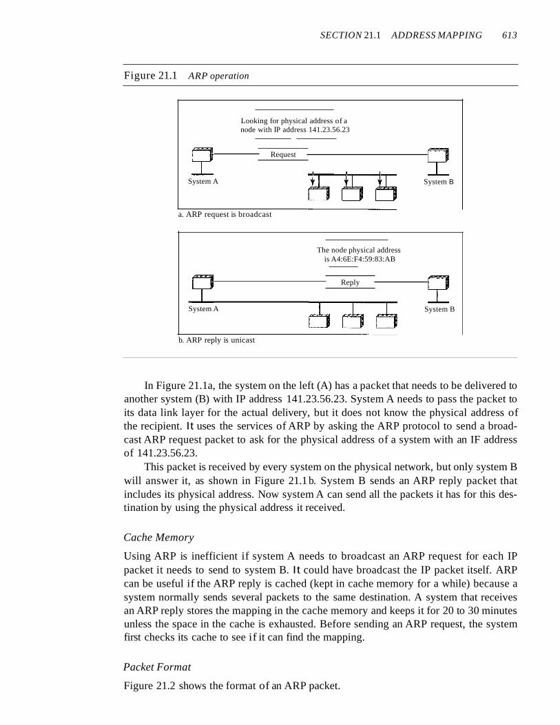
Figure 21.1 ARP operation
Looking for physical address of anode with IP address 141.23.56.23
Request
System A
a. ARP request is broadcast
System A
b. ARP reply is unicast
The node physical addressis A4:6E:F4:59:83:AB
Reply
System B
System B
In Figure 21.1a, the system on the left (A) has a packet that needs to be delivered toanother system (B) with IP address 141.23.56.23. System A needs to pass the packet toits data link layer for the actual delivery, but it does not know the physical address ofthe recipient. It uses the services of ARP by asking the ARP protocol to send a broadcast ARP request packet to ask for the physical address of a system with an IF addressof 141.23.56.23.
This packet is received by every system on the physical network, but only system Bwill answer it, as shown in Figure 21.1 b. System B sends an ARP reply packet thatincludes its physical address. Now system A can send all the packets it has for this destination by using the physical address it received.
Cache Memory
Using ARP is inefficient if system A needs to broadcast an ARP request for each IPpacket it needs to send to system B. It could have broadcast the IP packet itself. ARPcan be useful if the ARP reply is cached (kept in cache memory for a while) because asystem normally sends several packets to the same destination. A system that receivesan ARP reply stores the mapping in the cache memory and keeps it for 20 to 30 minutesunless the space in the cache is exhausted. Before sending an ARP request, the systemfirst checks its cache to see if it can find the mapping.
Packet Format
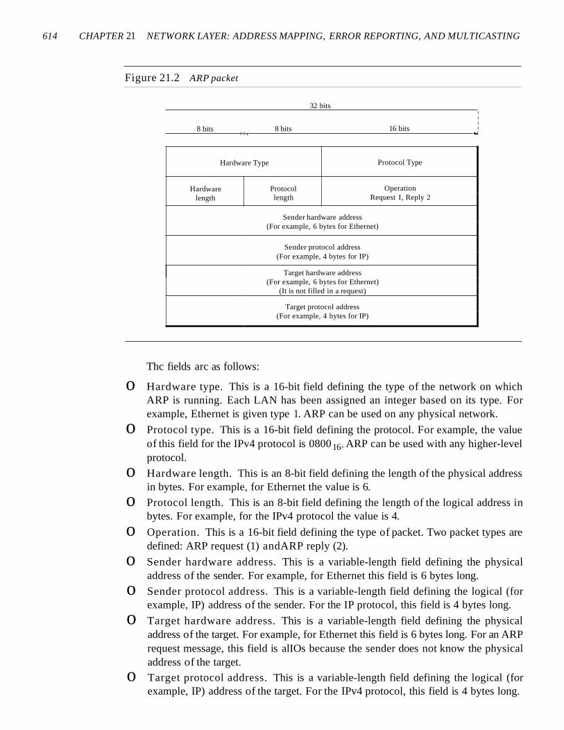
Figure 21.2 shows the format of an ARP packet.
614 CHAPTER 21 NETWORK LAYER: ADDRESS MAPPING, ERROR REPORTING, AND MULTICASTING
Figure 21.2 ARP packet
32 bits
8 bitsl I ~
8 bits 16 bits
IIII
_I
Hardware Type Protocol Type
Hardware Protocol Operationlength length Request I, Reply 2
Sender hardware address(For example, 6 bytes for Ethernet)
Sender protocol address(For example, 4 bytes for IP)
Target hardware address(For example, 6 bytes for Ethernet)
(It is not filled in a request)
Target protocol address(For example, 4 bytes for IP)
Thc fields arc as follows:
o Hardware type. This is a 16-bit field defining the type of the network on whichARP is running. Each LAN has been assigned an integer based on its type. Forexample, Ethernet is given type 1. ARP can be used on any physical network.
o Protocol type. This is a 16-bit field defining the protocol. For example, the valueof this field for the IPv4 protocol is 080016, ARP can be used with any higher-levelprotocol.
o Hardware length. This is an 8-bit field defining the length of the physical addressin bytes. For example, for Ethernet the value is 6.
o Protocol length. This is an 8-bit field defining the length of the logical address inbytes. For example, for the IPv4 protocol the value is 4.
o Operation. This is a 16-bit field defining the type of packet. Two packet types aredefined: ARP request (1) andARP reply (2).
o Sender hardware address. This is a variable-length field defining the physicaladdress of the sender. For example, for Ethernet this field is 6 bytes long.
o Sender protocol address. This is a variable-length field defining the logical (forexample, IP) address of the sender. For the IP protocol, this field is 4 bytes long.
o Target hardware address. This is a variable-length field defining the physicaladdress of the target. For example, for Ethernet this field is 6 bytes long. For an ARPrequest message, this field is alIOs because the sender does not know the physicaladdress of the target.
o Target protocol address. This is a variable-length field defining the logical (forexample, IP) address of the target. For the IPv4 protocol, this field is 4 bytes long.
SECTION 21.1 ADDRESS MAPPING 615
Encapsulation
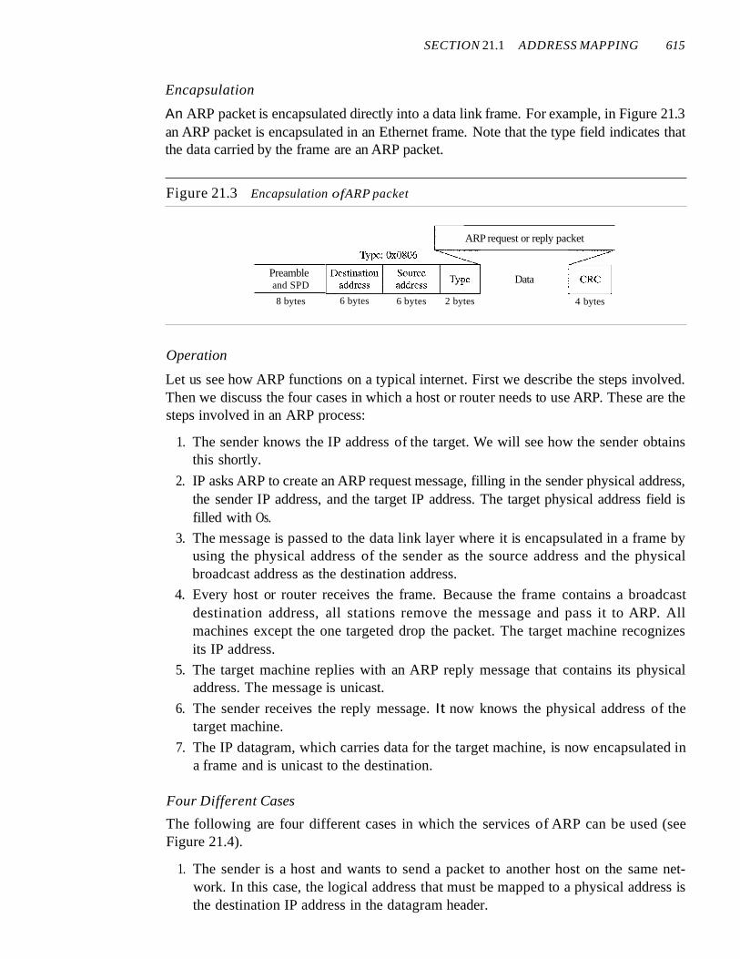
An ARP packet is encapsulated directly into a data link frame. For example, in Figure 21.3an ARP packet is encapsulated in an Ethernet frame. Note that the type field indicates thatthe data carried by the frame are an ARP packet.
Figure 21.3 Encapsulation ofARP packet
ARP request or reply packet
Preambleand SPD
8 bytes 6 bytes 6 bytes 2 bytes
Data
4 bytes
Operation
Let us see how ARP functions on a typical internet. First we describe the steps involved.Then we discuss the four cases in which a host or router needs to use ARP. These are thesteps involved in an ARP process:
1. The sender knows the IP address of the target. We will see how the sender obtainsthis shortly.
2. IP asks ARP to create an ARP request message, filling in the sender physical address,the sender IP address, and the target IP address. The target physical address field isfilled with Os.
3. The message is passed to the data link layer where it is encapsulated in a frame byusing the physical address of the sender as the source address and the physicalbroadcast address as the destination address.
4. Every host or router receives the frame. Because the frame contains a broadcastdestination address, all stations remove the message and pass it to ARP. Allmachines except the one targeted drop the packet. The target machine recognizesits IP address.
5. The target machine replies with an ARP reply message that contains its physicaladdress. The message is unicast.
6. The sender receives the reply message. It now knows the physical address of thetarget machine.
7. The IP datagram, which carries data for the target machine, is now encapsulated ina frame and is unicast to the destination.
Four Different Cases
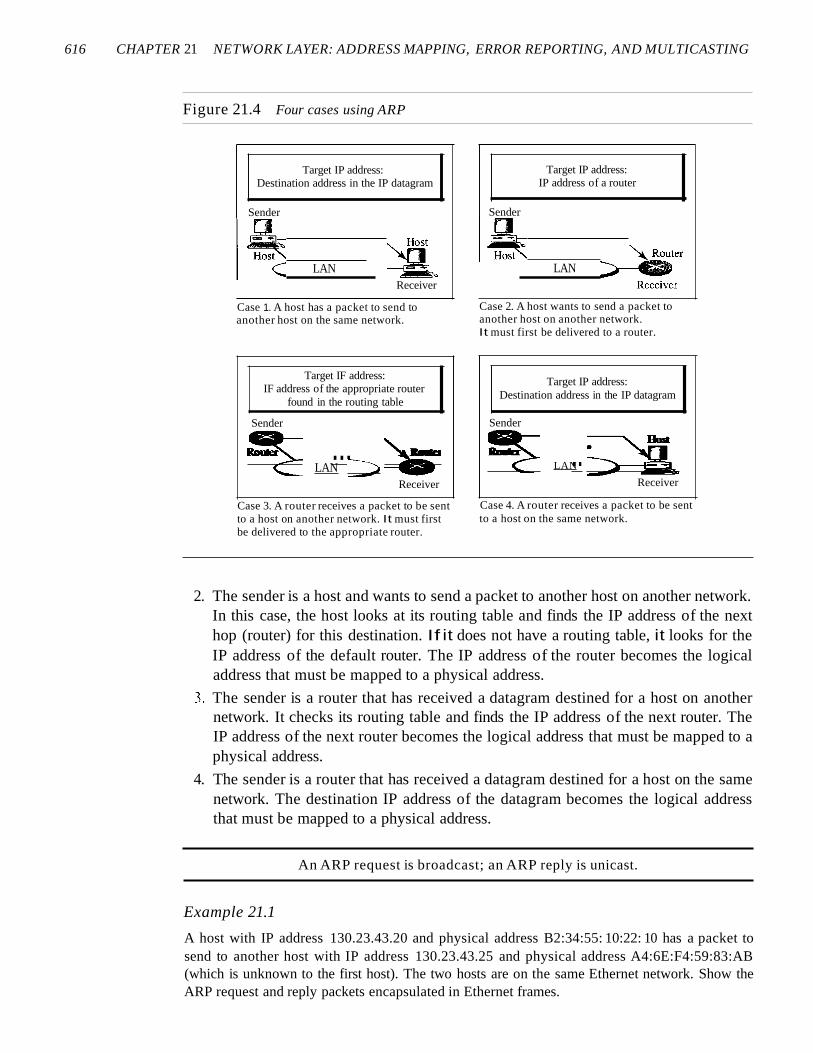
The following are four different cases in which the services of ARP can be used (seeFigure 21.4).
1. The sender is a host and wants to send a packet to another host on the same network. In this case, the logical address that must be mapped to a physical address isthe destination IP address in the datagram header.
616 CHAPTER 21 NETWORK LAYER: ADDRESS MAPPING, ERROR REPORTING, AND MULTICASTING
Figure 21.4 Four cases using ARP
Target IP address:Destination address in the IP datagram
Sender
LANReceiver
Case 1. A host has a packet to send toanother host on the same network.
Target IF address:IF address of the appropriate router
found in the routing table
Sender
~ ... )a~LAN ::;;.
Receiver
Case 3. A router receives a packet to be sentto a host on another network. It must firstbe delivered to the appropriate router.
Target IP address:IP address of a router
Sender
LAN
Case 2. A host wants to send a packet toanother host on another network.It must first be delivered to a router.
Target IP address:Destination address in the IP datagram
Sender
~ ..~LAN ="'"'-
Receiver
Case 4. A router receives a packet to be sentto a host on the same network.
2. The sender is a host and wants to send a packet to another host on another network.In this case, the host looks at its routing table and finds the IP address of the nexthop (router) for this destination. If it does not have a routing table, it looks for theIP address of the default router. The IP address of the router becomes the logicaladdress that must be mapped to a physical address.
3. The sender is a router that has received a datagram destined for a host on anothernetwork. It checks its routing table and finds the IP address of the next router. TheIP address of the next router becomes the logical address that must be mapped to aphysical address.
4. The sender is a router that has received a datagram destined for a host on the samenetwork. The destination IP address of the datagram becomes the logical addressthat must be mapped to a physical address.
An ARP request is broadcast; an ARP reply is unicast.
Example 21.1
A host with IP address 130.23.43.20 and physical address B2:34:55: 10:22: 10 has a packet tosend to another host with IP address 130.23.43.25 and physical address A4:6E:F4:59:83:AB(which is unknown to the first host). The two hosts are on the same Ethernet network. Show theARP request and reply packets encapsulated in Ethernet frames.
SECTION 21.1 ADDRESS MAPPlNG 617
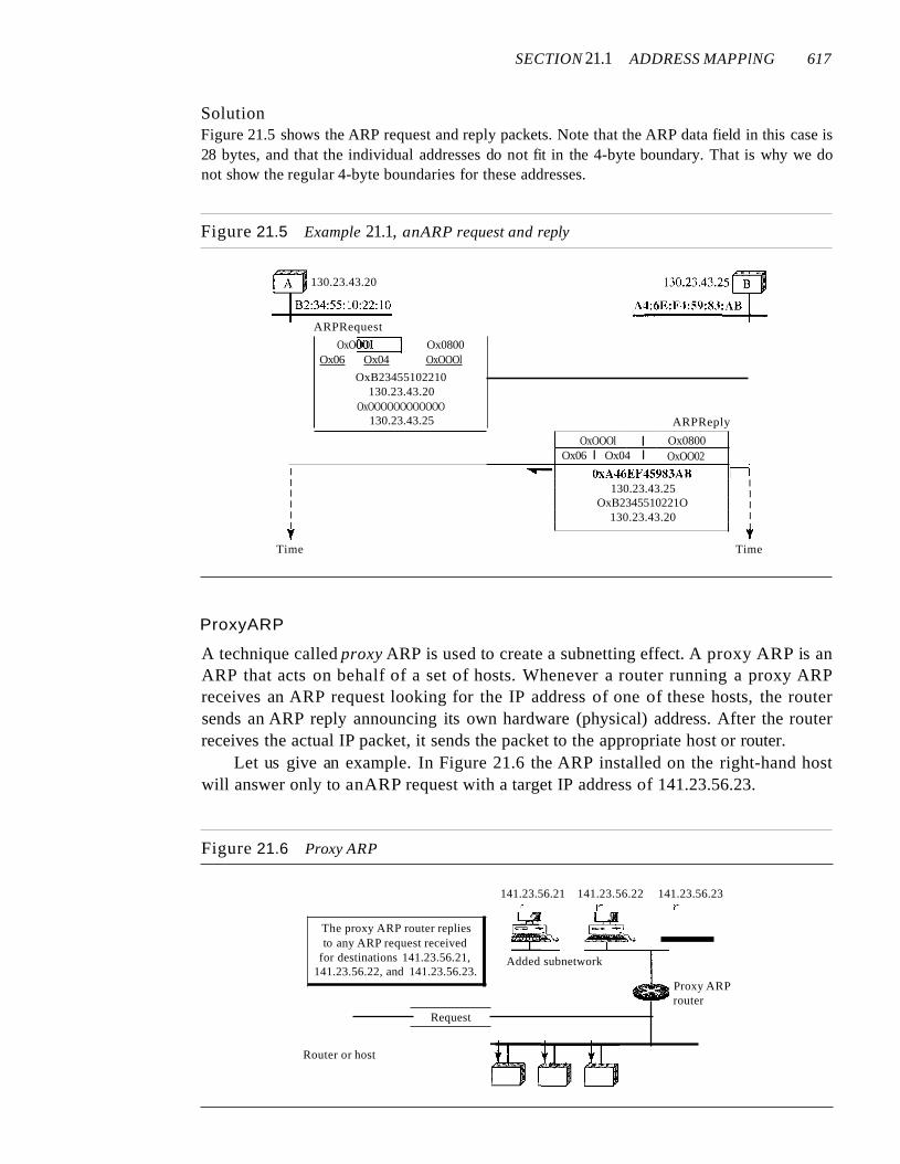
SolutionFigure 21.5 shows the ARP request and reply packets. Note that the ARP data field in this case is28 bytes, and that the individual addresses do not fit in the 4-byte boundary. That is why we donot show the regular 4-byte boundaries for these addresses.
Figure 21.5 Example 21.1, anARP request and reply
130.23.43.20
ARPRequest
OxOOOI Ox0800Ox06 Ox04 OxOOOl
OxB23455102210130.23.43.20
OxOOOOOOOOOOOO130.23.43.25 ARPReply
rTime
OxOOOl I Ox0800Ox06 I Ox04 I OxOO02
I ......- OxA.t6EF45983AB HI 130.23.43.25 II II OxB2345510221O II 130.23.43.20 II Iy
Time
ProxyARP
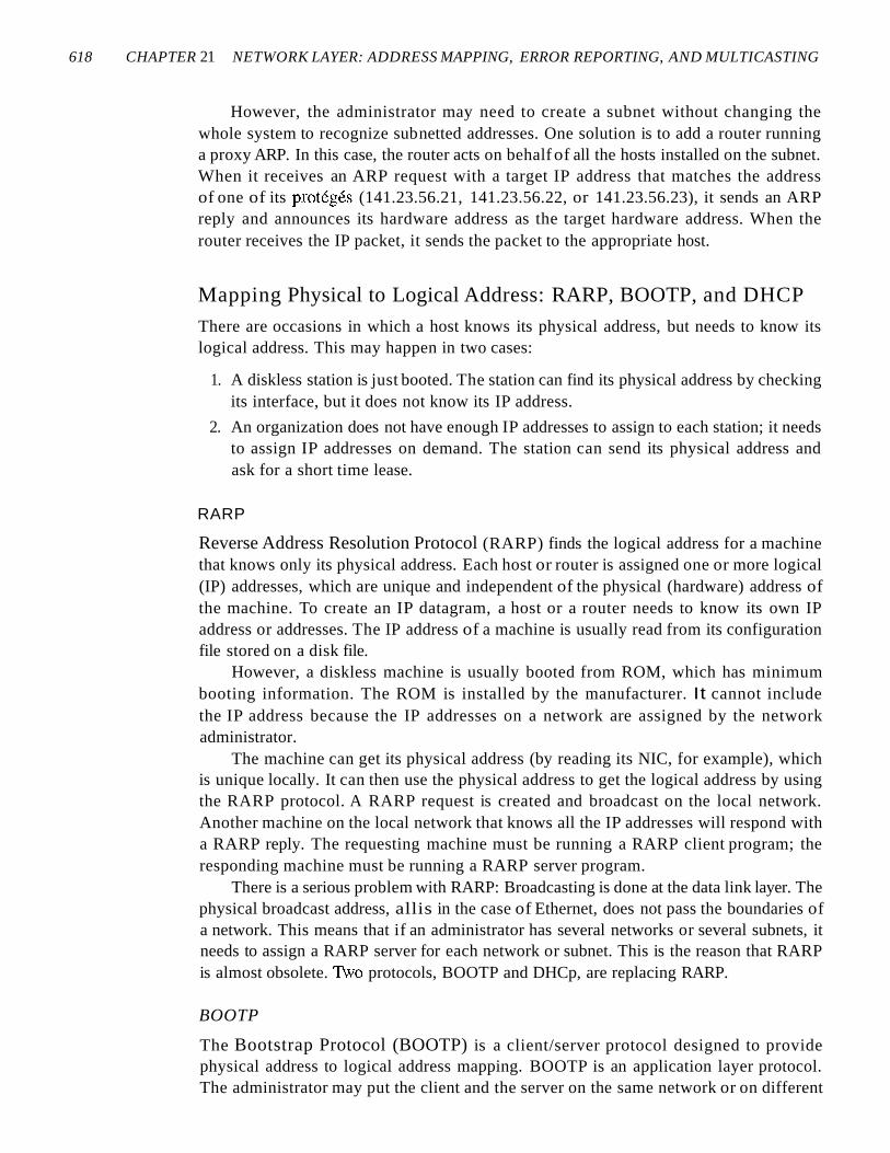
A technique called proxy ARP is used to create a subnetting effect. A proxy ARP is anARP that acts on behalf of a set of hosts. Whenever a router running a proxy ARPreceives an ARP request looking for the IP address of one of these hosts, the routersends an ARP reply announcing its own hardware (physical) address. After the routerreceives the actual IP packet, it sends the packet to the appropriate host or router.
Let us give an example. In Figure 21.6 the ARP installed on the right-hand hostwill answer only to anARP request with a target IP address of 141.23.56.23.
Figure 21.6 Proxy ARP
141.23.56.21 141.23.56.22 141.23.56.23r r r
Added subnetwork
The proxy ARP router repliesto any ARP request received
for destinations 141.23.56.21,141.23.56.22, and 141.23.56.23.
Proxy ARProuter
Request
Router or host
618 CHAPTER 21 NETWORK LAYER: ADDRESS MAPPING, ERROR REPORTING, AND MULTICASTING
However, the administrator may need to create a subnet without changing thewhole system to recognize subnetted addresses. One solution is to add a router runninga proxy ARP. In this case, the router acts on behalf of all the hosts installed on the subnet.When it receives an ARP request with a target IP address that matches the addressof one of its proteges (141.23.56.21, 141.23.56.22, or 141.23.56.23), it sends an ARPreply and announces its hardware address as the target hardware address. When therouter receives the IP packet, it sends the packet to the appropriate host.
Mapping Physical to Logical Address: RARP, BOOTP, and DHCP
There are occasions in which a host knows its physical address, but needs to know itslogical address. This may happen in two cases:
1. A diskless station is just booted. The station can find its physical address by checkingits interface, but it does not know its IP address.
2. An organization does not have enough IP addresses to assign to each station; it needsto assign IP addresses on demand. The station can send its physical address andask for a short time lease.
RARP
Reverse Address Resolution Protocol (RARP) finds the logical address for a machinethat knows only its physical address. Each host or router is assigned one or more logical(IP) addresses, which are unique and independent of the physical (hardware) address ofthe machine. To create an IP datagram, a host or a router needs to know its own IPaddress or addresses. The IP address of a machine is usually read from its configurationfile stored on a disk file.
However, a diskless machine is usually booted from ROM, which has minimumbooting information. The ROM is installed by the manufacturer. It cannot includethe IP address because the IP addresses on a network are assigned by the networkadministrator.
The machine can get its physical address (by reading its NIC, for example), whichis unique locally. It can then use the physical address to get the logical address by usingthe RARP protocol. A RARP request is created and broadcast on the local network.Another machine on the local network that knows all the IP addresses will respond witha RARP reply. The requesting machine must be running a RARP client program; theresponding machine must be running a RARP server program.
There is a serious problem with RARP: Broadcasting is done at the data link layer. Thephysical broadcast address, allis in the case of Ethernet, does not pass the boundaries ofa network. This means that if an administrator has several networks or several subnets, itneeds to assign a RARP server for each network or subnet. This is the reason that RARPis almost obsolete. 1\vo protocols, BOOTP and DHCp, are replacing RARP.
BOOTP
The Bootstrap Protocol (BOOTP) is a client/server protocol designed to providephysical address to logical address mapping. BOOTP is an application layer protocol.The administrator may put the client and the server on the same network or on different

SECTION 21.1 ADDRESS MAPPING 619
networks, as shown in Figure 21.7. BOOTP messages are encapsulated in a UDP packet,and the UDP packet itself is encapsulated in an IP packet.
Figure 21.7 BOOTP client and server on the same and different network
D
BOOTPClient
BOOTPDServer
I Request~~ Reply
a. Client and server on the same network
c::=Jo+Broadcastrequest
server
DBOOTP
c:::=::Jo+Unicastrequest
Internet
Relay agent--~'" ......I "-
I \, \\ I\ I
" i'...... /~ .--
DBOOTPClient
b. Client and server on different networks
The reader may ask how a client can send an IP datagram when it knows neitherits own IP address (the source address) nor the server's IP address (the destinationaddress). The client simply uses all as as the source address and allIs as the destinationaddress.
One of the advantages of BOOTP over RARP is that the client and server areapplication-layer processes. As in other application-layer processes, a client can be inone network and the server in another, separated by several other networks. However,there is one problem that must be solved. The BOOTP request is broadcast because theclient does not know the IP address of the server. A broadcast IP datagram cannot passthrough any router. To solve the problem, there is a need for an intermediary. One of thehosts (or a router that can be configured to operate at the application layer) can be usedas a relay. The host in this case is called a relay agent. The relay agent knows the unicastaddress of a BOOTP server. When it receives this type of packet, it encapsulates themessage in a unicast datagram and sends the request to the BOOTP server. The packet,
620 CHAPTER 21 NETWORK LAYER: ADDRESS MAPPING, ERROR REPORTING, AND MULTICASTING
carrying a unicast destination address, is routed by any router and reaches the BOOTPserver. The BOOTP server knows the message comes from a relay agent because one ofthe fields in the request message defines the IP address of the relay agent. The relayagent, after receiving the reply, sends it to the BOOTP client.
DHCP
BOOTP is not a dynamic configuration protocol. When a client requests its IPaddress, the BOOTP server consults a table that matches the physical address of the clientwith its IP address. This implies that the binding between the physical address and theIP address of the client already exists. The binding is predetermined.
However, what if a host moves from one physical network to another? What if ahost wants a temporary IP address? BOOTP cannot handle these situations because thebinding between the physical and IP addresses is static and fixed in a table until changedby the administrator. BOOTP is a static configuration protocol.
The Dynamic Host Configuration Protocol (DHCP) has been devised to providestatic and dynamic address allocation that can be manual or automatic.
DHCP provides static and dynamic address allocation that can be manual or automatic.
Static Address Allocation In this capacity DHCP acts as BOOTP does. It is backwardcompatible with BOOTP, which means a host running the BOOTP client can request astatic address from a DHCP server. A DHCP server has a database that statically bindsphysical addresses to IP addresses.
Dynamic Address Allocation DHCP has a second database with a pool of availableIP addresses. This second database makes DHCP dynamic. When a DHCP client requestsa temporary IP address, the DHCP server goes to the pool of available (unused) IPaddresses and assigns an IP address for a negotiable period of time.
When a DHCP client sends a request to a DHCP server, the server first checks itsstatic database. If an entry with the requested physical address exists in the static database, the permanent IP address of the client is returned. On the other hand, if the entrydoes not exist in the static database, the server selects an IP address from the availablepool, assigns the address to the client, and adds the entry to the dynamic database.
The dynamic aspect of DHCP is needed when a host moves from network to network or is connected and disconnected from a network (as is a subscriber to a serviceprovider). DHCP provides temporary IP addresses for a limited time.
The addresses assigned from the pool are temporary addresses. The DHCP serverissues a lease for a specific time. When the lease expires, the client must either stopusing the IP address or renew the lease. The server has the option to agree or disagreewith the renewal. If the server disagrees, the client stops using the address.
Manual and Automatic Configuration One major problem with the BOOTP protocolis that the table mapping the IP addresses to physical addresses needs to be manuallyconfigured. This means that every time there is a change in a physical or IP address, theadministrator needs to manually enter the changes. DHCP, on the other hand, allowsboth manual and automatic configurations. Static addresses are created manually~ dynamicaddresses are created automatically.
SECTION 21.2 ICMP 621
21.2 ICMPAs discussed in Chapter 20, the IP provides unreliable and connectionless datagramdelivery. It was designed this way to make efficient use of network resources. The IPprotocol is a best-effort delivery service that delivers a datagram from its originalsource to its final destination. However, it has two deficiencies: lack of error control andlack of assistance mechanisms.
The IP protocol has no error-reporting or error-correcting mechanism. What happensif something goes wrong? What happens if a router must discard a datagram because itcannot find a router to the final destination, or because the time-to-live field has a zerovalue? What happens if the final destination host must discard all fragments of a datagrambecause it has not received all fragments within a predetermined time limit? These areexamples of situations where an error has occurred and the IP protocol has no built-inmechanism to notify the original host.
The IP protocol also lacks a mechanism for host and management queries. A hostsometimes needs to determine if a router or another host is alive. And sometimes a network administrator needs information from another host or router.
The Internet Control Message Protocol (ICMP) has been designed to compensatefor the above two deficiencies. It is a companion to the IP protoco1.
Types of MessagesICMP messages are divided into two broad categories: error-reporting messages andquery messages.
The error-reporting messages report problems that a router or a host (destination)may encounter when it processes an IP packet.
The query messages, which occur in pairs, help a host or a network manager getspecific information from a router or another host. For example, nodes can discovertheir neighbors. Also, hosts can discover and learn about routers on their network, androuters can help a node redirect its messages.
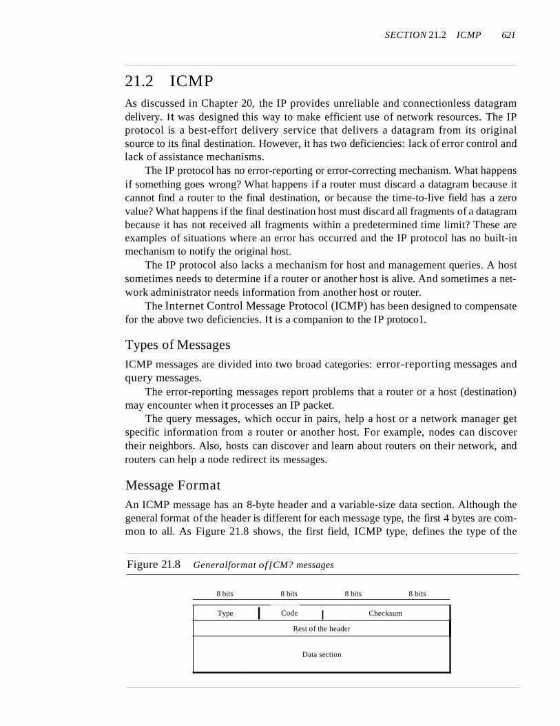
Message FormatAn ICMP message has an 8-byte header and a variable-size data section. Although thegeneral format of the header is different for each message type, the first 4 bytes are common to all. As Figure 21.8 shows, the first field, ICMP type, defines the type of the
Figure 21.8 Generalformat of [CM? messages
8 bits 8 bits 8 bits 8 bits
Type I Code I Checksum
Rest of the header
Data section

622 CHAPTER 21 NETWORK LAYER: ADDRESS MAPPING, ERROR REPORTING, AND MULTICASTING
message. The code field specifies the reason for the particular message type. The lastcommon field is the checksum field (to be discussed later in the chapter). The rest of theheader is specific for each message type.
The data section in error messages carries information for finding the originalpacket that had the error. In query messages, the data section carries extra informationbased on the type of the query.
Error ReportingOne of the main responsibilities of ICMP is to report errors. Although technology hasproduced increasingly reliable transmission media, errors still exist and must be handled.IP, as discussed in Chapter 20, is an unreliable protocol. This means that error checkingand error control are not a concern of IP. ICMP was designed, in part, to compensate forthis shortcoming. However, ICMP does not correct errors-it simply reports them. Errorcorrection is left to the higher-level protocols. Error messages are always sent to the original source because the only information available in the datagram about the route is thesource and destination IP addresses. ICMP uses the source IP address to send the errormessage to the source (originator) of the datagram.
ICMP always reports error messages to the original source.
Five types of errors are handled: destination unreachable, source quench, timeexceeded, parameter problems, and redirection (see Figure 21.9).
Figure 21.9 Error-reporting messages
Errorreporting
Timeexceeded
Type: 11 Type: 5
The following are important points about ICMP error messages:
o No ICMP error message will be generated in response to a datagram carrying anICMP error message.
D No ICMP error message will be generated for a fragmented datagram that is notthe first fragment.
D No IeMP error message will be generated for a datagram having a multicastaddress.
D No ICMP error message will be generated for a datagram having a special addresssuch as 127.0.0.0 or 0.0.0.0.
SECTION 21.2 ICMP 623
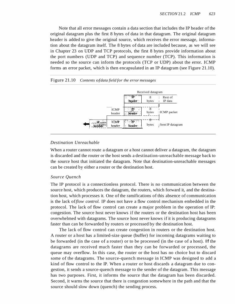
Note that all error messages contain a data section that includes the IP header of theoriginal datagram plus the first 8 bytes of data in that datagram. The original datagramheader is added to give the original source, which receives the error message, information about the datagram itself. The 8 bytes of data are included because, as we will seein Chapter 23 on UDP and TCP protocols, the first 8 bytes provide information aboutthe port numbers (UDP and TCP) and sequence number (TCP). This information isneeded so the source can inform the protocols (TCP or UDP) about the error. ICMPforms an error packet, which is then encapsulated in an IP datagram (see Figure 21.10).
Figure 21.10 Contents ofdata field for the error messages
8 : Rest ofbytes I IP data
Received datagram
ICMPheader
.-- ~~---~_-_----J8 I
bytes :ICMP packet
~_-~~~~j....---------;-"c-+----"""""'~"""""_m 8 I
bytes :Sent IP datagram___-'===~ J
Destination Unreachable
When a router cannot route a datagram or a host cannot deliver a datagram, the datagramis discarded and the router or the host sends a destination-unreachable message back tothe source host that initiated the datagram. Note that destination-unreachable messagescan be created by either a router or the destination host.
Source Quench
The IP protocol is a connectionless protocol. There is no communication between thesource host, which produces the datagram, the routers, which forward it, and the destination host, which processes it. One of the ramifications of this absence of communicationis the lack of flow control. IP does not have a flow control mechanism embedded in theprotocol. The lack of flow control can create a major problem in the operation of IP:congestion. The source host never knows if the routers or the destination host has beenoverwhelmed with datagrams. The source host never knows if it is producing datagramsfaster than can be forwarded by routers or processed by the destination host.
The lack of flow control can create congestion in routers or the destination host.A router or a host has a limited-size queue (buffer) for incoming datagrams waiting tobe forwarded (in the case of a router) or to be processed (in the case of a host). If thedatagrams are received much faster than they can be forwarded or processed, thequeue may overflow. In this case, the router or the host has no choice but to discardsome of the datagrams. The source-quench message in ICMP was designed to add akind of flow control to the IP. When a router or host discards a datagram due to congestion, it sends a source-quench message to the sender of the datagram. This messagehas two purposes. First, it informs the source that the datagram has been discarded.Second, it warns the source that there is congestion somewhere in the path and that thesource should slow down (quench) the sending process.
624 CHAPTER 21 NETWORK LAYER: ADDRESS MAPPING, ERROR REPORTING, AND MULTICASTING
Time Exceeded
The time-exceeded message is generated in two cases: As we see in Chapter 22, routersuse routing tables to find the next hop (next router) that must receive the packet. If thereare errors in one or more routing tables, a packet can travel in a loop or a cycle, goingfrom one router to the next or visiting a series of routers endlessly. As we saw in Chapter 20, each datagram contains a field called time to live that controls this situation.When a datagram visits a router, the value of this field is decremented by 1. When thetime-to-live value reaches 0, after decrementing, the router discards the datagram. However, when the datagram is discarded, a time-exceeded message must be sent by therouter to the original source. Second, a time-exceeded message is also generated whennot all fragments that make up a message arrive at the destination host within a certaintime limit.
Parameter Problem
Any ambiguity in the header part of a datagram can Create serious problems as the datagram travels through the Internet. If a router or the destination host discovers an ambiguous or missing value in any field of the datagram, it discards the datagram and sends aparameter-problem message back to the source.
Redirection
When a router needs to send a packet destined for another network, it must know the IPaddress of the next appropriate router. The same is true if the sender is a host. Both routersand hosts, then, must have a routing table to find the address of the router or the nextrouter. Routers take part in the routing update process, as we will see in Chapter 22, andare supposed to be updated constantly. Routing is dynamic.
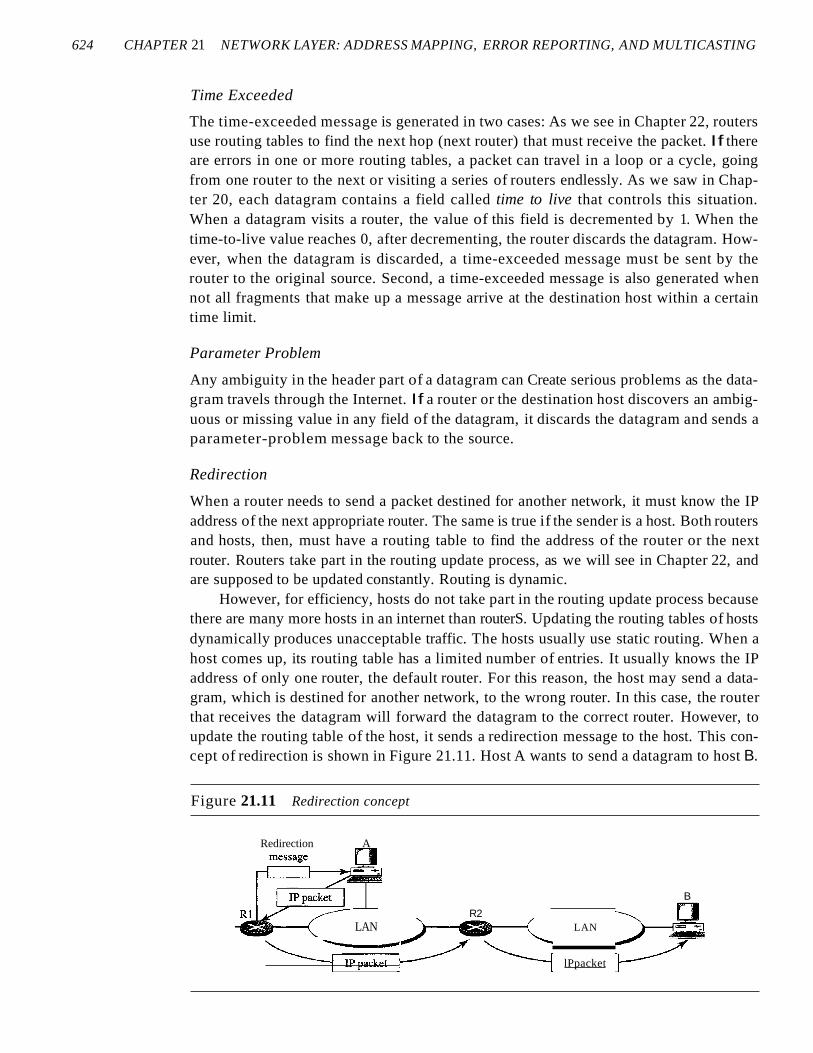
However, for efficiency, hosts do not take part in the routing update process becausethere are many more hosts in an internet than routerS. Updating the routing tables of hostsdynamically produces unacceptable traffic. The hosts usually use static routing. When ahost comes up, its routing table has a limited number of entries. It usually knows the IPaddress of only one router, the default router. For this reason, the host may send a datagram, which is destined for another network, to the wrong router. In this case, the routerthat receives the datagram will forward the datagram to the correct router. However, toupdate the routing table of the host, it sends a redirection message to the host. This concept of redirection is shown in Figure 21.11. Host A wants to send a datagram to host B.
Figure 21.11 Redirection concept
Redirection A
LAN
~:::lP:::p::ac::ke::t::::
R2LAN
lPpacket
B
SECTION 21.2 ICMP 625
Router R2 is obviously the most efficient routing choice, but host A did not chooserouter R2. The datagram goes to R1 instead. Router R1, after consulting its table, findsthat the packet should have gone to R2. It sends the packet to R2 and, at the same time,sends a redirection message to host A. Host A's routing table can now be updated.
Query
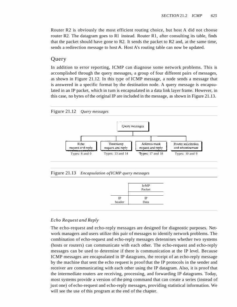
In addition to error reporting, ICMP can diagnose some network problems. This isaccomplished through the query messages, a group of four different pairs of messages,as shown in Figure 21.12. In this type of ICMP message, a node sends a message thatis answered in a specific format by the destination node. A query message is encapsulated in an IP packet, which in tum is encapsulated in a data link layer frame. However, inthis case, no bytes of the original IP are included in the message, as shown in Figure 21.13.
Figure 21.12 Query messages
Types: 8 and 0 Types: 13 and 14 Types: 17 and 18 Types: 10 and 9
Figure 21.13 Encapsulation ofICMP query messages
IeMPPacket
IP IPheader Data
Echo Request and Reply
The echo-request and echo-reply messages are designed for diagnostic purposes. Network managers and users utilize this pair of messages to identify network problems. Thecombination of echo-request and echo-reply messages detennines whether two systems(hosts or routers) can communicate with each other. The echo-request and echo-replymessages can be used to determine if there is communication at the IP level. BecauseICMP messages are encapsulated in IP datagrams, the receipt of an echo-reply messageby the machine that sent the echo request is proof that the IP protocols in the sender andreceiver are communicating with each other using the IP datagram. Also, it is proof thatthe intermediate routers are receiving, processing, and forwarding IP datagrams. Today,most systems provide a version of the ping command that can create a series (instead ofjust one) of echo-request and echo-reply messages, providing statistical information. Wewill see the use of this program at the end of the chapter.
626 CHAPTER 21 NETWORK lAYER: ADDRESS MAPPING, ERROR REPORTING, AND MULTICASTING
Timestamp Request and Reply
Two machines (hosts or routers) can use the timestamp request and timestamp replymessages to determine the round-trip time needed for an IP datagram to travel betweenthem. It can also be used to synchronize the clocks in two machines.
Address-Mask Request and Reply
A host may know its IP address, but it may not know the corresponding mask. Forexample, a host may know its IP address as 159.31.17.24, but it may not know that thecorresponding mask is /24. To obtain its mask, a host sends an address-mask-requestmessage to a router on the LAN. If the host knows the address of the router, it sends therequest directly to the router. If it does not know, it broadcasts the message. The routerreceiving the address-mask-request message responds with an address-mask-replymessage, providing the necessary mask for the host. This can be applied to its full IPaddress to get its subnet address.
Router Solicitation and Advertisement
As we discussed in the redirection message section, a host that wants to send data to a hoston another network needs to know the address of routers connected to its own network.Also, the host must know if the routers are alive and functioning. The router-solicitationand router-advertisement messages can help in this situation. A host can broadcast (ormulticast) a router-solicitation message. The router or routers that receive the solicitationmessage broadcast their routing information using the router-advertisement message. Arouter can also periodically send router-advertisement messages even if no host has solicited. Note that when a router sends out an advertisement, it announces not only its ownpresence but also the presence of all routers on the network of which it is aware.
Checksum
In Chapter 10, we learned the concept and idea of the checksum. In ICMP the checksumis calculated over the entire message (header and data).
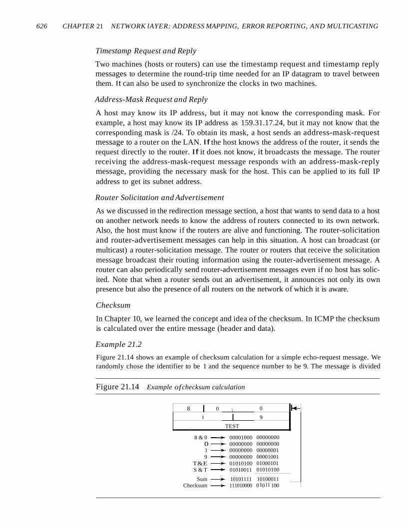
Example 21.2
Figure 21.14 shows an example of checksum calculation for a simple echo-request message. Werandomly chose the identifier to be 1 and the sequence number to be 9. The message is divided
Figure 21.14 Example ofchecksum calculation
Checksum~ 111010000 0 0 100
8 I 0 \ 0 k-I I 9
TEST
8 & 0~ 00001000 00000000o~ 00000000 000000001~ 00000000 000000019~ 00000000 00001001
T&E~ 01010100 01000101S & T~ 01010011 01010100
Sum~ 10101111 101000111 11
SECTION 21.2 ICMP 627
into 16-bit (2-byte) words. The words are added and the sum is complemented. Now the sendercan put this value in the checksum field.
Debugging Tools
There are several tools that can be used in the Internet for debugging. We can determinethe viability of a host or router. We can trace the route of a packet. We introduce twotools that use ICMP for debugging: ping and traceroute. We will introduce more toolsin future chapters after we have discussed the corresponding protocols.
Ping
We can use the ping program to find if a host is alive and responding. We use ping hereto see how it uses ICMP packets.
The source host sends ICMP echo-request messages (type: 8, code: 0); the destination, if alive, responds with ICMP echo-reply messages. The ping program sets the identifier field in the echo-request and echo-reply message and stans the sequence numberfrom 0; this number is incremented by 1 each time a new message is sent. Note that pingcan calculate the round-trip time. It inserts the sending time in the data section of themessage. When the packet arrives, it subtracts the arrival time from the departure time toget the round-trip time (RTT).
Example 21.3
We use the ping program to test the server fhda.edu. The result is shown below:
$ ping thda.eduPING thda.edu (153.18.8.1) 56 (84) bytes of data.64 bytes from tiptoe.fhda.edu (153.18.8.1): icmp_seq=O64 bytes from tiptoe.fhda.edu (153.18.8.1): icmp_seq=l64 bytes from tiptoe.fhda.edu (153.18.8.1): icmp_seq=264 bytes from tiptoe.fhda.edu (153.18.8.1): icmp_seq=364 bytes from tiptoe.fhda.edu (153.18.8.1): icmp_seq=464 bytes from tiptoe.fhda.edu (153.18.8.1): icmp_seq=564 bytes from tiptoe.fhda.edu (153.18.8.1): icmp_seq=664 bytes from tiptoe.:fhda.edu (153.18.8.1): icmp_seq=764 bytes from tiptoe.:fhda.edu (153.18.8.1): icmp_seq=864 bytes from tiptoe.fhda.edu (153.18.8.1): icmp_seq=964 bytes from tiptoe.:fhda.edu (153.18.8.1): icmp_seq=lO
ttl=62ttl=62ttl=62ttl=62ttl=62ttl=62tt1=62ttl=62ttl=62ttl=62ttl==62
time=1.91 mstime:=2.04 mstime=1.90 mstime=1.97 mstime=1.93 mstime=2.00 mstime=1.94 mstime=1.94 mstime=1.97 mstime=1.89 mstime=1.98 ms
--- thda.edu ping statistics ---11 packets transmitted, 11 received, 0% packet loss, time 10103ms
rtt minJavg/max = 1.899/1.955/2.041 ms
The ping program sends messages with sequence numbers starting from O. For each probe itgives us the RTT time. The TTL (time to live) field in the IP datagram that encapsulates an ICMPmessage has been set to 62, which means the packet cannot travel mare than 62 hops. At the beginning, ping defines the number of data bytes as 56 and the total number of bytes as 84. It is obviousthat if we add 8 bytes of ICMP header and 20 bytes of IP header to 56, the result is 84. However,
628 CHAPTER 21 NETWORK IAYER: ADDRESS MAPPING, ERROR REPORTiNG, AND MULTiCASTING
note that in each probe ping defines the number of bytes as 64. This is the total number of bytes inthe ICMP packet (56 + 8). The ping program continues to send messages, if we do not stop it byusing the interrupt key (ctrl + c, for example). After it is interrupted, it prints the statistics of theprobes. It tells us the number of packets sent, the number of packets received, the total time, andthe RTT minimum, maximum, and average. Some systems may print more infonnation.
Tracerollte
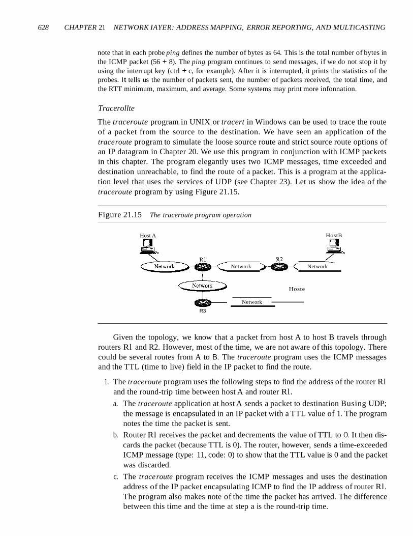
The traceroute program in UNIX or tracert in Windows can be used to trace the routeof a packet from the source to the destination. We have seen an application of thetraceroute program to simulate the loose source route and strict source route options ofan IP datagram in Chapter 20. We use this program in conjunction with ICMP packetsin this chapter. The program elegantly uses two ICMP messages, time exceeded anddestination unreachable, to find the route of a packet. This is a program at the application level that uses the services of UDP (see Chapter 23). Let us show the idea of thetraceroute program by using Figure 21.15.
Figure 21.15 The traceroute program operation
Host A
Network
Network
R3
Hoste
HostB
Network
Given the topology, we know that a packet from host A to host B travels throughrouters Rl and R2. However, most of the time, we are not aware of this topology. Therecould be several routes from A to B. The traceroute program uses the ICMP messagesand the TTL (time to live) field in the IP packet to find the route.
1. The traceroute program uses the following steps to find the address of the router Rland the round-trip time between host A and router Rl.
a. The traceroute application at host A sends a packet to destination Busing UDP;the message is encapsulated in an IP packet with a TTL value of 1. The programnotes the time the packet is sent.
b. Router Rl receives the packet and decrements the value of TTL to O. It then discards the packet (because TTL is 0). The router, however, sends a time-exceededICMP message (type: 11, code: 0) to show that the TTL value is 0 and the packetwas discarded.
c. The traceroute program receives the ICMP messages and uses the destinationaddress of the IP packet encapsulating ICMP to find the IP address of router Rl.The program also makes note of the time the packet has arrived. The differencebetween this time and the time at step a is the round-trip time.
SECTION 21.2 ICMP 629
The traceroute program repeats steps a to c three times to get a better averageround-trip time. The first trip time may be much longer than the second or thirdbecause it takes time for the ARP program to find the physical address of routerRI. For the second and third trips, ARP has the address in its cache.
2. The traceroute program repeats the previous steps to find the address of router R2and the round-trip time between host A and router R2. However, in this step, thevalue of TTL is set to 2. So router RI forwards the message, while router R2 discards it and sends a time-exceeded ICMP message.
3. The traceroute program repeats step 2 to find the address of host B and the round-triptime between host A and host B. When host B receives the packet, it decrements thevalue of TIL, but it does not discard the message since it has reached its final destination. How can an ICMP message be sent back to host A? The traceroute programuses a different strategy here. The destination port of the UDP packet is set to onethat is not supported by the UDP protocol. When host B receives the packet, it cannotfind an application program to accept the delivery. It discards the packet and sends anICMP destination-unreachable message (type: 3, code: 3) to host A. Note that thissituation does not happen at router RI or R2 because a router does not check theUDP header. The traceroute program records the destination address of the arrivedIP datagram and makes note of the round-trip time. Receiving the destinationunreachable message with a code value 3 is an indication that the whole route hasbeen found and there is no need to send more packets.
Example 21.4
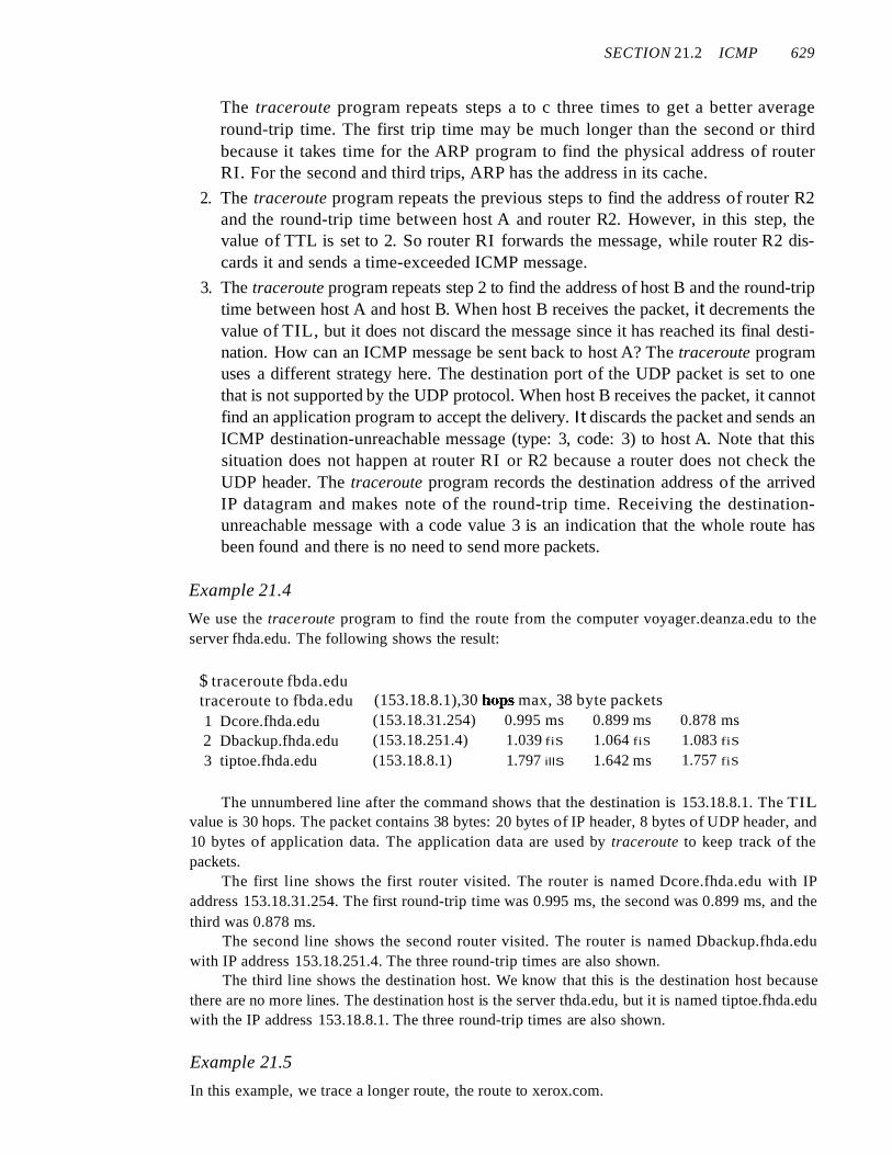
We use the traceroute program to find the route from the computer voyager.deanza.edu to theserver fhda.edu. The following shows the result:
$ traceroute fbda.edutraceroute to fbda.edu1 Dcore.fhda.edu2 Dbackup.fhda.edu3 tiptoe.fhda.edu
(153.18.8.1),30 hops max, 38 byte packets(153.18.31.254) 0.995 ms 0.899 ms(153.18.251.4) 1.039 fiS 1.064 fiS
(153.18.8.1) 1.797 illS 1.642 ms
0.878 ms1.083 fiS
1.757 fiS
The unnumbered line after the command shows that the destination is 153.18.8.1. The TILvalue is 30 hops. The packet contains 38 bytes: 20 bytes of IP header, 8 bytes of UDP header, and10 bytes of application data. The application data are used by traceroute to keep track of thepackets.
The first line shows the first router visited. The router is named Dcore.fhda.edu with IPaddress 153.18.31.254. The first round-trip time was 0.995 ms, the second was 0.899 ms, and thethird was 0.878 ms.
The second line shows the second router visited. The router is named Dbackup.fhda.eduwith IP address 153.18.251.4. The three round-trip times are also shown.
The third line shows the destination host. We know that this is the destination host becausethere are no more lines. The destination host is the server thda.edu, but it is named tiptoe.fhda.eduwith the IP address 153.18.8.1. The three round-trip times are also shown.
Example 21.5
In this example, we trace a longer route, the route to xerox.com.

630 CHAPTER 21 NETWORK LAYER: ADDRESS MAPPING, ERROR REPORTING, AND MULTICASTING
$ traceroute xerox.comtraceroute to xerox.com (13.1.64.93), 30 hops max, 38 byte packets
1 Dcore.fbda.edu (153.18.31.254) 0.622 ms 0.891 ms2 Ddmz.fbda.edu (153.18.251.40) 2.132 ms 2.266 ms3 Cinic.fhda.edu (153.18.253.126) 2.110 ms 2.145 ms4 cenic.net (137.164.32.140) 3.069 ms 2.875 ms5 cenic.net (137.164.22.31) 4.205 ms 4.870 ms
0.875 ms2.094ms1.763 ms2.930ms4.197 ms
14 snfc21.pbi.net (151.164.191.49) 7.656 ms 7.129 ms 6.866ms15 sbcglobaLnet (151.164.243.58) 7.844 ms 7.545 ms 7.353 ms16 pacbell.net (209.232.138.114) 9.857 ms 9.535 ms 9.603 ms17 209.233.48.223 (209.233.48.223) 10.634ms 10.771 ms 10.592 ms18 alpha.Xerox.COM (13.1.64.93) 11.172 ms 11.048 ms 10.922ms
Here there are 17 hops between source and destination. Note that some round-trip times lookunusual. It could be that a router was too busy to process the packet immediately.
21.3 IGMPThe IP protocol can be involved in two types of communication: unicasting and multicasting. Unicasting is the communication between one sender and one receiver. It is aone-to-one communication. However, some processes sometimes need to send the samemessage to a large number of receivers simultaneously. This is called multicasting,which is a one-to-many communication. Multicasting has many applications. For example, multiple stockbrokers can simultaneously be informed of changes in a stock price,or travel agents can be informed of a plane cancellation. Some other applications includedistance learning and video-on-demand.
The Internet Group Management Protocol (IGMP) is one of the necessary, butnot sufficient (as we will see), protocols that is involved in multicasting. IGMP is acompanion to the IP protocol.
Group ManagementFor multicasting in the Internet we need routers that are able to route multicast packets.The routing tables of these routers must be updated by using one of the multicastingrouting protocols that we discuss in Chapter 22.
IGMP is not a multicasting routing protocol; it is a protocol that manages groupmembership. In any network, there are one or more multicast routers that distributemulticast packets to hosts or other routers. The IGMP protocol gives the multicast routersinformation about the membership status of hosts (routers) connected to the network.
A multicast router may receive thousands of multicast packets every day for differentgroups. If a router has no knowledge about the membership status of the hosts, it mustbroadcast all these packets. This creates a lot of traffic and consumes bandwidth. A bettersolution is to keep a list of groups in the network for which there is at least one loyalmember. IGMP helps the multicast router create and update this list.
SECTION 21.3 IGMP 631
IGMP is a group management protocol. It helps a multicast router createand update a list of loyal members related to each router interface.
IGMP Messages
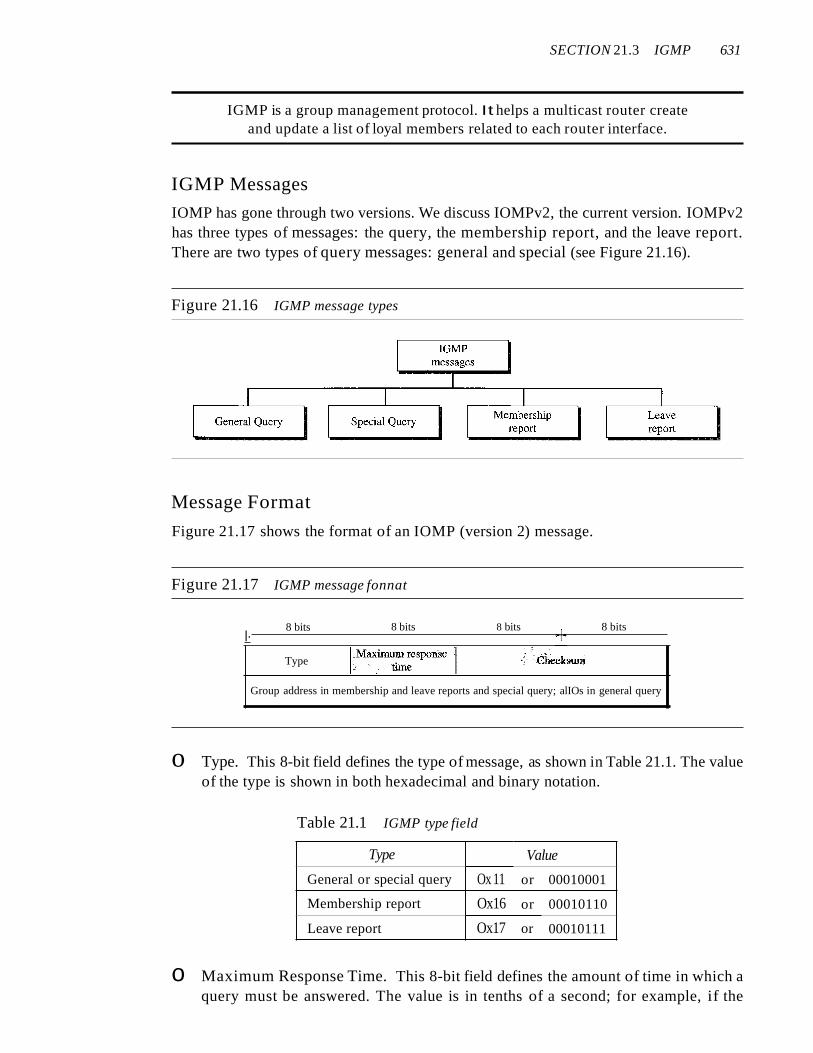
IOMP has gone through two versions. We discuss IOMPv2, the current version. IOMPv2has three types of messages: the query, the membership report, and the leave report.There are two types of query messages: general and special (see Figure 21.16).
Figure 21.16 IGMP message types
Message Format
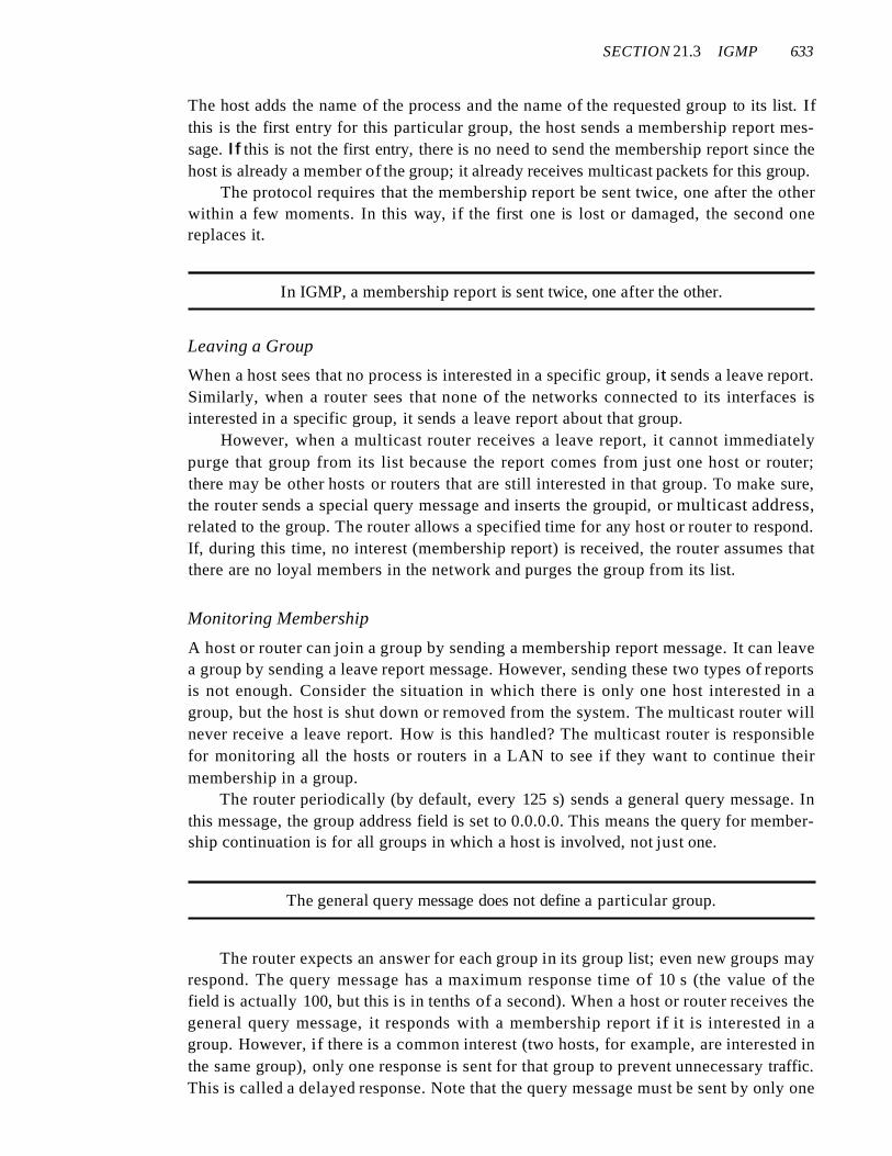
Figure 21.17 shows the format of an IOMP (version 2) message.
Figure 21.17 IGMP message fonnat
I·8 bits
Type
8 bits
l~axim~ response t
Ie time
8 bits 8 bits
Group address in membership and leave reports and special query; alIOs in general query
o Type. This 8-bit field defines the type of message, as shown in Table 21.1. The valueof the type is shown in both hexadecimal and binary notation.
Table 21.1 IGMP type field
Type Value
General or special query Ox 11 or 00010001
Membership report Ox16 or 00010110
Leave report Ox17 or 00010111
o Maximum Response Time. This 8-bit field defines the amount of time in which aquery must be answered. The value is in tenths of a second; for example, if the
632 CHAPTER 21 NETWORK LAYER: ADDRESS MAPPING, ERROR REPORTING, AND MULTICASTING
value is 100, it means 10 s. The value is nonzero in the query message; it is set tozero in the other two message types. We will see its use shortly.
D Checksum. This is a 16-bit field carrying the checksum. The checksum is calculatedover the 8-byte message.
D Group address. The value of this field is 0 for a general query message. The valuedefines the groupid (multicast address of the group) in the special query, the membership report, and the leave report messages.
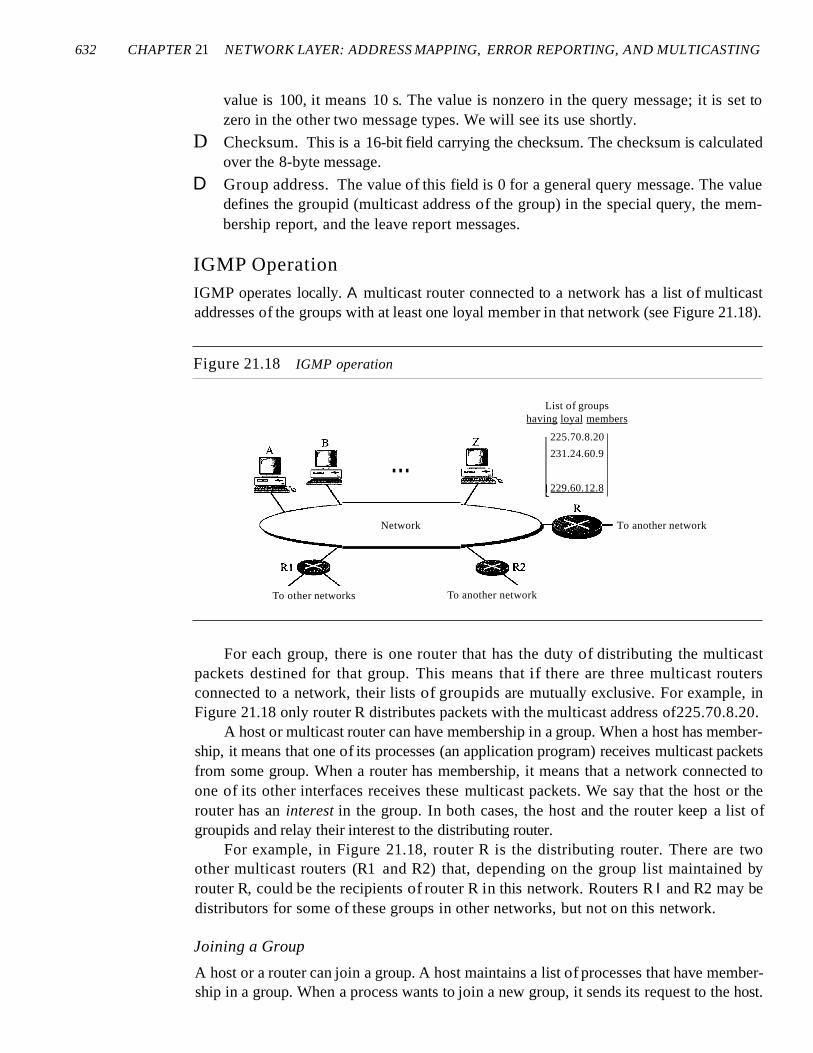
IGMP OperationIGMP operates locally. A multicast router connected to a network has a list of multicastaddresses of the groups with at least one loyal member in that network (see Figure 21.18).
Figure 21.18 IGMP operation
To another network
229.60.12.8
...
Network
List of groupshaving loyal members
225.70.8.20
231.24.60.9
To other networks To another network
For each group, there is one router that has the duty of distributing the multicastpackets destined for that group. This means that if there are three multicast routersconnected to a network, their lists of groupids are mutually exclusive. For example, inFigure 21.18 only router R distributes packets with the multicast address of225.70.8.20.
A host or multicast router can have membership in a group. When a host has membership, it means that one of its processes (an application program) receives multicast packetsfrom some group. When a router has membership, it means that a network connected toone of its other interfaces receives these multicast packets. We say that the host or therouter has an interest in the group. In both cases, the host and the router keep a list ofgroupids and relay their interest to the distributing router.
For example, in Figure 21.18, router R is the distributing router. There are twoother multicast routers (R1 and R2) that, depending on the group list maintained byrouter R, could be the recipients of router R in this network. Routers R I and R2 may bedistributors for some of these groups in other networks, but not on this network.
Joining a Group
A host or a router can join a group. A host maintains a list of processes that have membership in a group. When a process wants to join a new group, it sends its request to the host.
SECTION 21.3 IGMP 633
The host adds the name of the process and the name of the requested group to its list. Ifthis is the first entry for this particular group, the host sends a membership report message. If this is not the first entry, there is no need to send the membership report since thehost is already a member of the group; it already receives multicast packets for this group.
The protocol requires that the membership report be sent twice, one after the otherwithin a few moments. In this way, if the first one is lost or damaged, the second onereplaces it.
In IGMP, a membership report is sent twice, one after the other.
Leaving a Group
When a host sees that no process is interested in a specific group, it sends a leave report.Similarly, when a router sees that none of the networks connected to its interfaces isinterested in a specific group, it sends a leave report about that group.
However, when a multicast router receives a leave report, it cannot immediatelypurge that group from its list because the report comes from just one host or router;there may be other hosts or routers that are still interested in that group. To make sure,the router sends a special query message and inserts the groupid, or multicast address,related to the group. The router allows a specified time for any host or router to respond.If, during this time, no interest (membership report) is received, the router assumes thatthere are no loyal members in the network and purges the group from its list.
Monitoring Membership
A host or router can join a group by sending a membership report message. It can leavea group by sending a leave report message. However, sending these two types of reportsis not enough. Consider the situation in which there is only one host interested in agroup, but the host is shut down or removed from the system. The multicast router willnever receive a leave report. How is this handled? The multicast router is responsiblefor monitoring all the hosts or routers in a LAN to see if they want to continue theirmembership in a group.
The router periodically (by default, every 125 s) sends a general query message. Inthis message, the group address field is set to 0.0.0.0. This means the query for membership continuation is for all groups in which a host is involved, not just one.
The general query message does not define a particular group.
The router expects an answer for each group in its group list; even new groups mayrespond. The query message has a maximum response time of 10 s (the value of thefield is actually 100, but this is in tenths of a second). When a host or router receives thegeneral query message, it responds with a membership report if it is interested in agroup. However, if there is a common interest (two hosts, for example, are interested inthe same group), only one response is sent for that group to prevent unnecessary traffic.This is called a delayed response. Note that the query message must be sent by only one
634 CHAPTER 21 NETWORK LAYER: ADDRESS MAPPING, ERROR REPORTING, AND MULTICASTING
router (normally called the query router), also to prevent unnecessary traffic. We discussthis issue shortly.
Delayed Response
To prevent unnecessary traffic, IGMP uses a delayed response strategy. When a host orrouter receives a query message, it does not respond immediately; it delays the response.Each host or router uses a random number to create a timer, which expires between I andlOs. The expiration time can be in steps of I s or less. A timer is set for each group in thelist. For example, the timer for the first group may expire in 2 s, but the timer for the thirdgroup may expire in 5 s. Each host or router waits until its timer has expired before sending a membership report message. During this waiting time, if the timer of another host orrouter, for the same group, expires earlier, that host or router sends a membership report.Because, as we will see shortly, the report is broadcast, the waiting host or router receivesthe report and knows that there is no need to send a duplicate report for this group; thus,the waiting station cancels its corresponding timer.
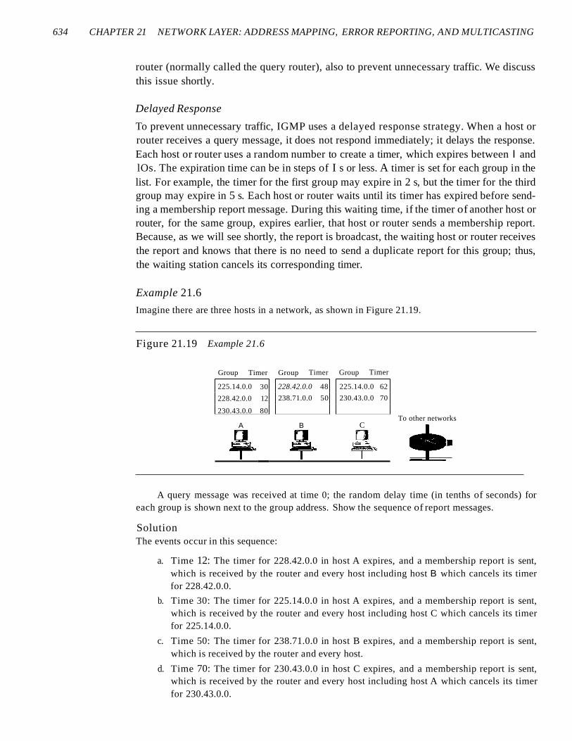
Example 21.6
Imagine there are three hosts in a network, as shown in Figure 21.19.
Figure 21.19 Example 21.6
Group Timer Group Timer Group Timer
225.14.0.0 30 228.42.0.0 48 225.14.0.0 62
228.42.0.0 12 238.71.0.0 50 230.43.0.0 70
230.43.0.0 80To other networks
A B C
~R~ ~ ¥-A query message was received at time 0; the random delay time (in tenths of seconds) for
each group is shown next to the group address. Show the sequence of report messages.
SolutionThe events occur in this sequence:
a. Time 12: The timer for 228.42.0.0 in host A expires, and a membership report is sent,which is received by the router and every host including host B which cancels its timerfor 228.42.0.0.
b. Time 30: The timer for 225.14.0.0 in host A expires, and a membership report is sent,which is received by the router and every host including host C which cancels its timerfor 225.14.0.0.
c. Time 50: The timer for 238.71.0.0 in host B expires, and a membership report is sent,which is received by the router and every host.
d. Time 70: The timer for 230.43.0.0 in host C expires, and a membership report is sent,which is received by the router and every host including host A which cancels its timerfor 230.43.0.0.
SECTION 21.3 IGMP 635
Note that if each host had sent a report for every group in its list, there would have been sevenreports; with this strategy only four reports are sent.
Query Router
Query messages may create a lot of responses. To prevent unnecessary traffic, IGMPdesignates one router as the query router for each network. Only this designated routersends the query message, and the other routers are passive (they receive responses andupdate their lists).
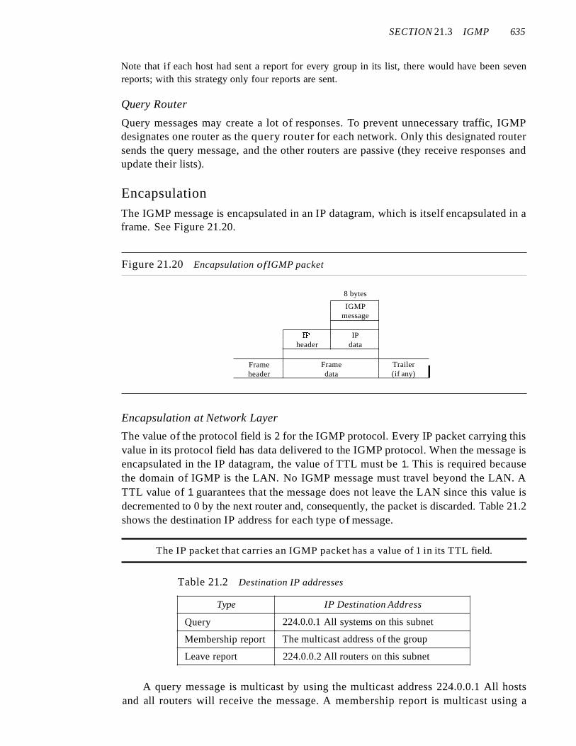
EncapsulationThe IGMP message is encapsulated in an IP datagram, which is itself encapsulated in aframe. See Figure 21.20.
Figure 21.20 Encapsulation ofIGMP packet
8 bytes
IGMPmessage
W IPheader data
Frame Frame Trailer
Iheader data (if any)
Encapsulation at Network Layer
The value of the protocol field is 2 for the IGMP protocol. Every IP packet carrying thisvalue in its protocol field has data delivered to the IGMP protocol. When the message isencapsulated in the IP datagram, the value of TTL must be 1. This is required becausethe domain of IGMP is the LAN. No IGMP message must travel beyond the LAN. ATTL value of 1 guarantees that the message does not leave the LAN since this value isdecremented to 0 by the next router and, consequently, the packet is discarded. Table 21.2shows the destination IP address for each type of message.
The IP packet that carries an IGMP packet has a value of 1 in its TTL field.
Table 21.2 Destination IP addresses
Type IP Destination Address
Query 224.0.0.1 All systems on this subnet
Membership report The multicast address of the group
Leave report 224.0.0.2 All routers on this subnet
A query message is multicast by using the multicast address 224.0.0.1 All hostsand all routers will receive the message. A membership report is multicast using a
636 CHAPTER 21 NETWORK LAYER: ADDRESS MAPPING, ERROR REPORTING, AND MULTICASTING
destination address equal to the multicast address being reported (groupid). Every station (host or router) that receives the packet can immediately determine (from theheader) the group for which a report has been sent. As discussed previously, the timersfor the corresponding unsent reports can then be canceled. Stations do not need to openthe packet to find the groupid. This address is duplicated in a packet; it's part of themessage itself and also a field in the IP header. The duplication prevents errors. A leavereport message is multicast using the multicast address 224.0.0.2 (all routers on thissubnet) so that routers receive this type of message. Hosts receive this message too, butdisregard it.
Encapsulation at Data Link Layer
At the network layer, the IGMP message is encapsulated in an IP packet and is treatedas an IP packet. However, because the IP packet has a multicast IP address, the ARPprotocol cannot find the corresponding MAC (physical) address to forward the packetat the data link layer. What happens next depends on whether the underlying data linklayer supports physical multicast addresses.
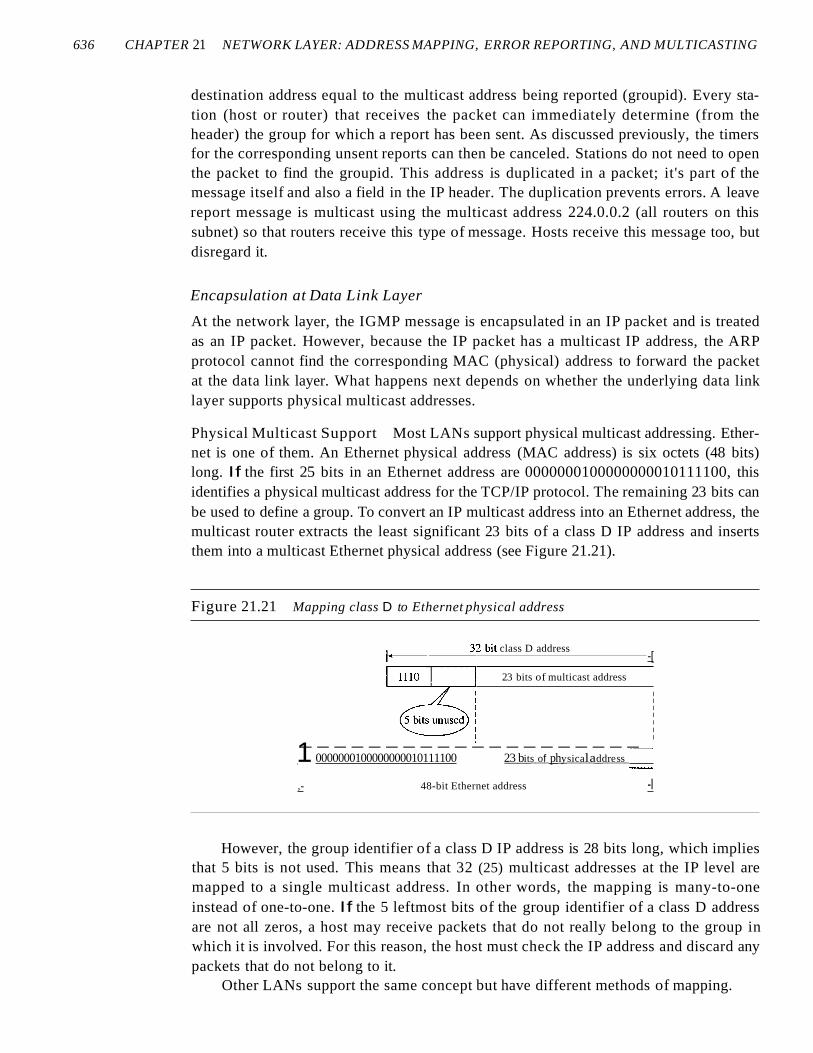
Physical Multicast Support Most LANs support physical multicast addressing. Ethernet is one of them. An Ethernet physical address (MAC address) is six octets (48 bits)long. If the first 25 bits in an Ethernet address are 0000000100000000010111100, thisidentifies a physical multicast address for the TCP/IP protocol. The remaining 23 bits canbe used to define a group. To convert an IP multicast address into an Ethernet address, themulticast router extracts the least significant 23 bits of a class D IP address and insertsthem into a multicast Ethernet physical address (see Figure 21.21).
Figure 21.21 Mapping class D to Ethernet physical address
-[
23 bits of multicast address
32-bit class D address
IIIIIII
--------------------,1 0000000100000000010111100 2__3__b__its__o__f __ph__y__sic__a__la__dd__re__s__s _I,- 48-bit Ethernet address -I
However, the group identifier of a class D IP address is 28 bits long, which impliesthat 5 bits is not used. This means that 32 (25) multicast addresses at the IP level aremapped to a single multicast address. In other words, the mapping is many-to-oneinstead of one-to-one. If the 5 leftmost bits of the group identifier of a class D addressare not all zeros, a host may receive packets that do not really belong to the group inwhich it is involved. For this reason, the host must check the IP address and discard anypackets that do not belong to it.
Other LANs support the same concept but have different methods of mapping.
SECTION 21.3 IGMP 637
An Ethernet multicast physical address is in the range01 :00:5E:00:OO:OO to 01:00:5E:7F:FF:FF.
Example 21.7
Change the multicast IP address 230.43.14.7 to an Ethernet multicast physical address.
SolutionWe can do this in two steps:
a. We write the rightmost 23 bits of the IP address in hexadecimal. This can be done by changingthe rightmost 3 bytes to hexadecimal and then subtracting 8 from the leftmost digit if it isgreater than or equal to 8. In our example, the result is 2B:OE:07.
b. We add the result of part a to the starting Ethernet multicast address, which is01:00:5E:00:00:00. The result is
01:00:5E:2B:OE:07
Example 21.8
Change the multicast IP address 238.212.24.9 to an Ethernet multicast address.
Solution
a. The rightmost 3 bytes in hexadecimal is D4: 18:09. We need to subtract 8 from the leftmostdigit, resulting in 54:18:09.
b. We add the result of part a to the Ethernet multicast starting address. The result is
01:00:5E:54: 18:09
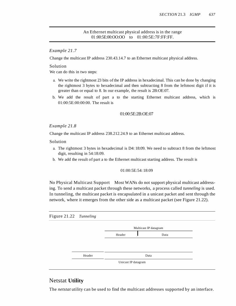
No Physical Multicast Support Most WANs do not support physical multicast addressing. To send a multicast packet through these networks, a process called tunneling is used.In tunneling, the multicast packet is encapsulated in a unicast packet and sent through thenetwork, where it emerges from the other side as a multicast packet (see Figure 21.22).
Figure 21.22 Tunneling
Multicast IP datagram
Header I Data
Header Data
Unicast IP datagram
Netstat Utility
The netstat utility can be used to find the multicast addresses supported by an interface.
638 CHAPTER 21 NETWORK LAYER: ADDRESS MAPPING, ERROR REPORTING, AND MULTICASTING
Example 21.9
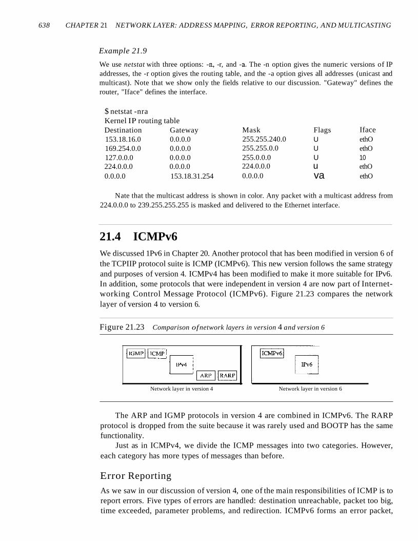
We use netstat with three options: -n, -r, and -a. The -n option gives the numeric versions of IPaddresses, the -r option gives the routing table, and the -a option gives all addresses (unicast andmulticast). Note that we show only the fields relative to our discussion. "Gateway" defines therouter, "Iface" defines the interface.
$ netstat -nraKernel IP routing tableDestination Gateway153.18.16.0 0.0.0.0169.254.0.0 0.0.0.0127.0.0.0 0.0.0.0224.0.0.0 0.0.0.00.0.0.0 153.18.31.254
Mask255.255.240.0255.255.0.0255.0.0.0224.0.0.00.0.0.0
FlagsUUUuva
IfaceethOethO10ethOethO
Nate that the multicast address is shown in color. Any packet with a multicast address from224.0.0.0 to 239.255.255.255 is masked and delivered to the Ethernet interface.
21.4 ICMPv6We discussed 1Pv6 in Chapter 20. Another protocol that has been modified in version 6 ofthe TCPIIP protocol suite is ICMP (ICMPv6). This new version follows the same strategyand purposes of version 4. ICMPv4 has been modified to make it more suitable for IPv6.In addition, some protocols that were independent in version 4 are now part of Internetworking Control Message Protocol (ICMPv6). Figure 21.23 compares the networklayer of version 4 to version 6.
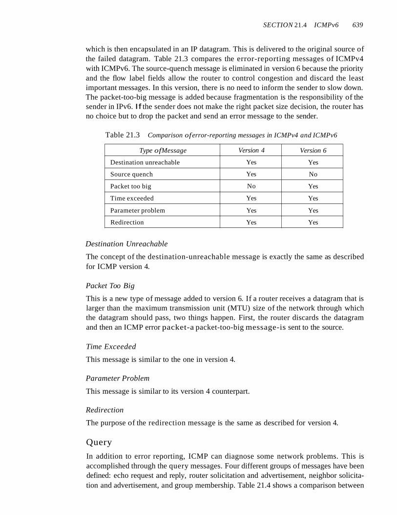
Figure 21.23 Comparison ofnetwork layers in version 4 and version 6
Network layer in version 4 Network layer in version 6
The ARP and IGMP protocols in version 4 are combined in ICMPv6. The RARPprotocol is dropped from the suite because it was rarely used and BOOTP has the samefunctionality.
Just as in ICMPv4, we divide the ICMP messages into two categories. However,each category has more types of messages than before.
Error Reporting
As we saw in our discussion of version 4, one of the main responsibilities of ICMP is toreport errors. Five types of errors are handled: destination unreachable, packet too big,time exceeded, parameter problems, and redirection. ICMPv6 forms an error packet,
SECTION 21.4 ICMPv6 639
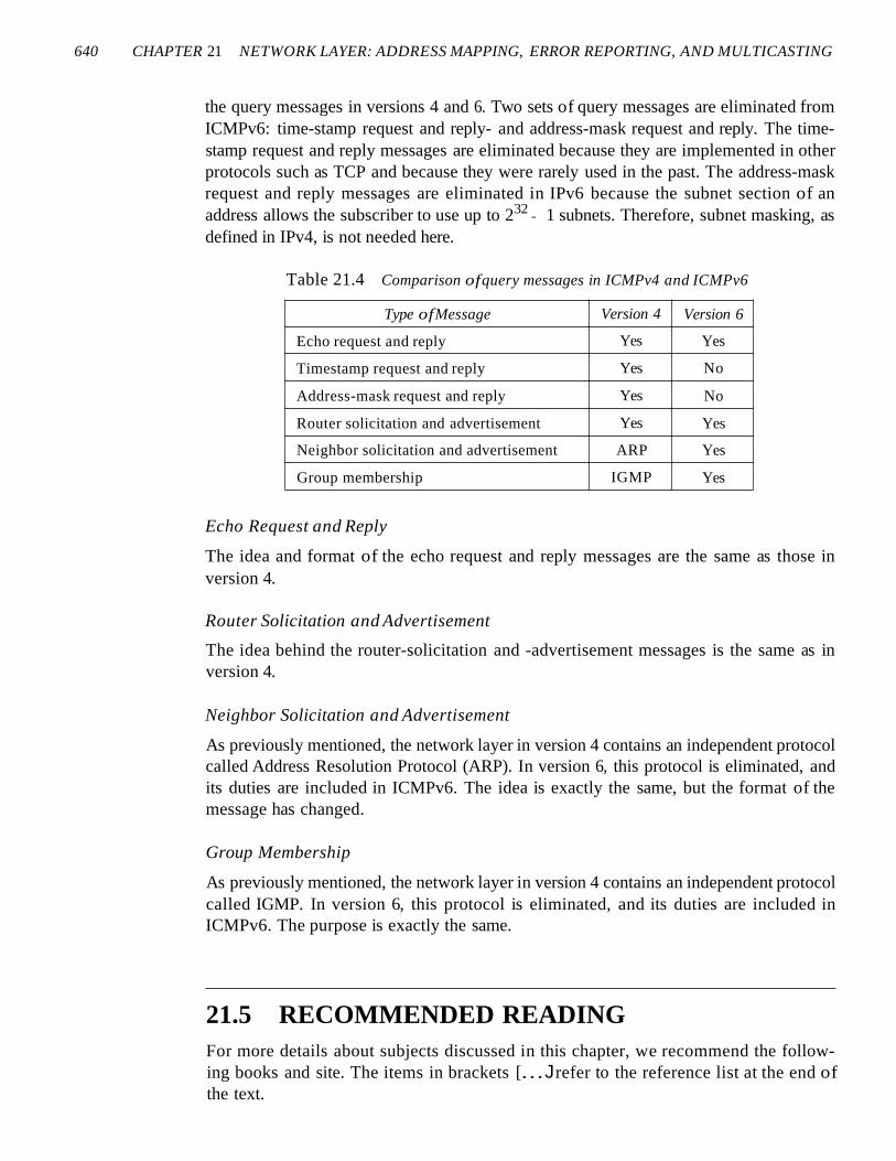
which is then encapsulated in an IP datagram. This is delivered to the original source ofthe failed datagram. Table 21.3 compares the error-reporting messages of ICMPv4with ICMPv6. The source-quench message is eliminated in version 6 because the priorityand the flow label fields allow the router to control congestion and discard the leastimportant messages. In this version, there is no need to inform the sender to slow down.The packet-too-big message is added because fragmentation is the responsibility of thesender in IPv6. If the sender does not make the right packet size decision, the router hasno choice but to drop the packet and send an error message to the sender.
Table 21.3 Comparison oferror-reporting messages in ICMPv4 and ICMPv6
Type ofMessage Version 4 Version 6
Destination unreachable Yes Yes
Source quench Yes No
Packet too big No Yes
Time exceeded Yes Yes
Parameter problem Yes Yes
Redirection Yes Yes
Destination Unreachable
The concept of the destination-unreachable message is exactly the same as describedfor ICMP version 4.
Packet Too Big
This is a new type of message added to version 6. If a router receives a datagram that islarger than the maximum transmission unit (MTU) size of the network through whichthe datagram should pass, two things happen. First, the router discards the datagramand then an ICMP error packet-a packet-too-big message-is sent to the source.
Time Exceeded
This message is similar to the one in version 4.
Parameter Problem
This message is similar to its version 4 counterpart.
Redirection
The purpose of the redirection message is the same as described for version 4.
Query
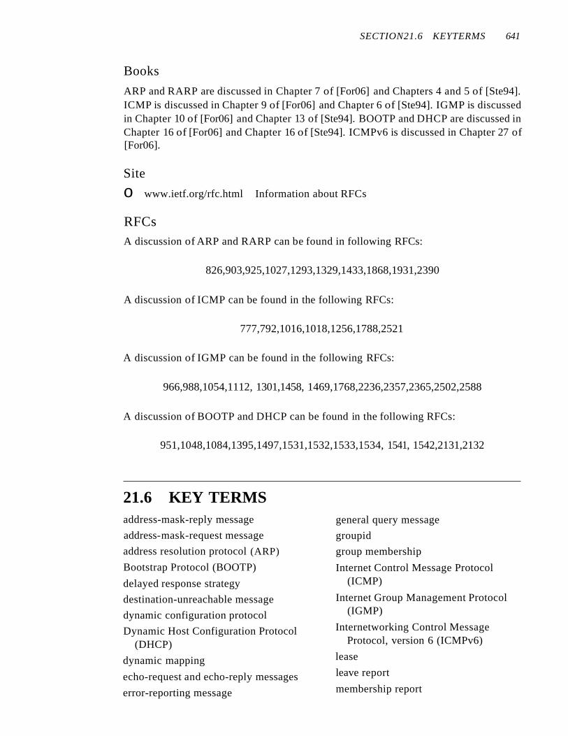
In addition to error reporting, ICMP can diagnose some network problems. This isaccomplished through the query messages. Four different groups of messages have beendefined: echo request and reply, router solicitation and advertisement, neighbor solicitation and advertisement, and group membership. Table 21.4 shows a comparison between
640 CHAPTER 21 NETWORK LAYER: ADDRESS MAPPING, ERROR REPORTING, AND MULTICASTING
the query messages in versions 4 and 6. Two sets of query messages are eliminated fromICMPv6: time-stamp request and reply- and address-mask request and reply. The timestamp request and reply messages are eliminated because they are implemented in otherprotocols such as TCP and because they were rarely used in the past. The address-maskrequest and reply messages are eliminated in IPv6 because the subnet section of anaddress allows the subscriber to use up to 232 - 1 subnets. Therefore, subnet masking, asdefined in IPv4, is not needed here.
Table 21.4 Comparison ofquery messages in ICMPv4 and ICMPv6
Type ofMessage Version 4 Version 6
Echo request and reply Yes Yes
Timestamp request and reply Yes No
Address-mask request and reply Yes No
Router solicitation and advertisement Yes Yes
Neighbor solicitation and advertisement ARP Yes
Group membership IGMP Yes
Echo Request and Reply
The idea and format of the echo request and reply messages are the same as those inversion 4.
Router Solicitation and Advertisement
The idea behind the router-solicitation and -advertisement messages is the same as inversion 4.
Neighbor Solicitation and Advertisement
As previously mentioned, the network layer in version 4 contains an independent protocolcalled Address Resolution Protocol (ARP). In version 6, this protocol is eliminated, andits duties are included in ICMPv6. The idea is exactly the same, but the format of themessage has changed.
Group Membership
As previously mentioned, the network layer in version 4 contains an independent protocolcalled IGMP. In version 6, this protocol is eliminated, and its duties are included inICMPv6. The purpose is exactly the same.
21.5 RECOMMENDED READINGFor more details about subjects discussed in this chapter, we recommend the following books and site. The items in brackets [...Jrefer to the reference list at the end ofthe text.
SECTION21.6 KEYTERMS 641
Books
ARP and RARP are discussed in Chapter 7 of [For06] and Chapters 4 and 5 of [Ste94].ICMP is discussed in Chapter 9 of [For06] and Chapter 6 of [Ste94]. IGMP is discussedin Chapter 10 of [For06] and Chapter 13 of [Ste94]. BOOTP and DHCP are discussed inChapter 16 of [For06] and Chapter 16 of [Ste94]. ICMPv6 is discussed in Chapter 27 of[For06].
Site
o www.ietf.org/rfc.html Information about RFCs
RFCsA discussion of ARP and RARP can be found in following RFCs:
826,903,925,1027,1293,1329,1433,1868,1931,2390
A discussion of ICMP can be found in the following RFCs:
777,792,1016,1018,1256,1788,2521
A discussion of IGMP can be found in the following RFCs:
966,988,1054,1112, 1301,1458, 1469,1768,2236,2357,2365,2502,2588
A discussion of BOOTP and DHCP can be found in the following RFCs:
951,1048,1084,1395,1497,1531,1532,1533,1534, 1541, 1542,2131,2132
21.6 KEY TERMSaddress-mask-reply message
address-mask-request message
address resolution protocol (ARP)
Bootstrap Protocol (BOOTP)
delayed response strategy
destination-unreachable message
dynamic configuration protocol
Dynamic Host Configuration Protocol(DHCP)
dynamic mapping
echo-request and echo-reply messages
error-reporting message
general query message
groupid
group membership
Internet Control Message Protocol(ICMP)
Internet Group Management Protocol(IGMP)
Internetworking Control MessageProtocol, version 6 (ICMPv6)
lease
leave report
membership report
642 CHAPTER 21 NETWORK LAYER: ADDRESS MAPPING, ERROR REPORTING, AND MULTICASTING
multicast address
multicast router
multicasting
neighbor-solicitation and advertisementmessage
packet-too-big message
parameter-problem message
physical address
proxyARP
query message
query router
redirection message
relay agent
reverse address resolution protocol(RARP)
router-solicitation and router-advertisement messages
source-quench message
special query message
static mapping
time-exceeded message
timestamp request and timestampreply messages
traceroute
tunneling
21.7 SUMMARYo Delivery of a packet to a host or router requires two levels of addresses: logical and
physical. A physical address identifies a host or router at the physical level.
o Mapping of a logical address to a physical address can be static or dynamic.
o Static mapping involves a list of logical and physical address correspondences;maintenance of the list requires high overhead.
o The address resolution protocol (ARP) is a dynamic mapping method that finds aphysical address, given a logical address.
o In proxy ARP, a router represents a set of hosts. When an ARP request seeks thephysical address of any host in this set, the router sends its own physical address.This creates a subnetting effect.
o Reverse Address Resolution Protocol (RARP) is a form of dynamic mapping inwhich a given physical address is associated with a logical address.
o ICMP sends four pairs of query messages: echo-request and echo-reply, time-stamprequest and reply, address-mask-request and -reply, and router solicitation andadvertisement.
D The checksum for ICMP is calculated by using both the header and the data fieldsof the ICMP message.
D Packet InterNet Groper (ping) is an application program that uses the services ofICMP to test the reachability of a host.
o Multicasting is the sending of the same message to more than one receiversimultaneously.
o The Internet Group Management Protocol (IGMP) helps multicast routers create andupdate a list of loyal members related to a router interface.
o The three IGMP message types are the query message, the membership report, andthe leave report.
SECTION 21.8 PRACTICE SET 643
D A delayed response strategy prevents unnecessary traffic on a LAN.
D The IGMP message is encapsulated in an IP datagram.
D Most LANs, including Ethernet, support physical multicast addressing.
D WANs that do not support physical multicast addressing can use a process calledtunneling to send multicast packets.
D BOOTP and Dynamic Host Configuration Protocol (DHCP) are client/server applications that deliver vital network information to either diskless computers or computersat first boot.
D A BOOTP request is encapsulated in a UDP user datagram.
D BOOTP, a static configuration protocol, uses a table that maps IP addresses tophysical addresses.
D A relay agent is a router that helps send local BOOTP requests to remote servers.
D DHCP is a dynamic configuration protocol with two databases: One is similar toBOOTP, and the other is a pool of IP addresses available for temporary assignment.
D The DHCP server issues a lease for an IP address to a client for a specific time.
D ICMPv6, like version 4, reports errors, handles group memberships, updates specificrouter and host tables, and checks the viability of a host.
21.8 PRACTICE SET
Review Questions
1. Is the size of the ARP packet fixed? Explain.
2. What is the size of an ARP packet when the protocol is IPv4 and the hardware isEthernet?
3. What is the size of an Ethernet frame carrying an ARP packet in Question 2?
4. What is the broadcast address for Ethernet?
5. Why is there a restriction on the generation of an ICMPv4 message in response toa failed ICMPv4 error message?
6. What is the purpose of including the IPv4 header and the first 8 bytes of datagramdata in the error-reporting ICMPv4 messages?
7. Give an example of a situation in which a host would never receive a redirectionmessage.
8. What is the minimum size of an ICMPv4 packet? What is the maximum size of anICMPv4 packet?
9. What is the minimum size of an IPv4 packet that carries an ICMPv4 packet? Whatis the maximum size?
10. How can we determine if an IPv4 packet is carrying an ICMPv4 packet?
11. What is the minimum size of an Ethernet frame that carries an IPv4 packet whichin turn carries an ICMPv4 packet? What is the maximum size?
12. Why is there no need for the ICMPv4 message to travel outside its own network?
644 CHAPTER 21 NETWORK LAYER: ADDRESS MAPPING, ERROR REPORTING, AND MULTICASTING
Exercises
13. A router with IPv4 address 125.45.23.12 and Ethernet physical address23:45:AB:4F:67:CD has received a packet for a host destination with IP address125.11.78.10. Show the entries in theARP request packet sent by the router. Assumeno subnetting.
14. Show the entries in the ARP packet sent in response to Exercise 13.
15. Encapsulate the result of Exercise 13 in a data link frame. Fill in all the fields.
16. Encapsulate the result of Exercise 14 in a data link frame. Fill in all the fields.
17. Host A sends a datagram to host B. Host B never receives the datagram, and host Anever receives notification of failure. Give two different explanations of what mighthave happened.
18. Calculate the checksum for the following ICMP packet:Type: Echo Request Identifier: 123 Sequence number: 25 Message: Hello
19. A router receives an IPv4 packet with source IP address 130.45.3.3 and destinationIP address 201.23.4.6. The router cannot find the destination IP address in its routingtable. Which ICMPv4 message should be sent?
20. TCP receives a segment with destination port address 234. TCP checks and cannotfind an open port for this destination. Which ICMPv4 message should be sent?
21. A multicast address for a group is 231.24.60.9. What is its 48-bit Ethernet addressfor a LAN using TCPIIP?
22. If a router has 20 entries in its group table, should it send 20 different queries periodically or just one? Explain your answer.
23. If a host wants to continue membership in five groups, should it send five differentmembership report messages or just one?
24. A router on an Ethernet network has received a multicast IP packet with groupid226.17.18.4. When the host checks its multicast group table, it finds this address.Show how the router sends this packet to the recipients by encapsulating the IPpacket in an Ethernet frame. Show all the entries of the Ethernet frame. The outgoingIP address of the router is 185.23.5.6, and its outgoing physical address is4A224512E1E2. Does the router need the services of ARP?
25. A host with IPv4 address 114.45.7.9 receives an IGMP query. When it checks itsgroup table, it finds no entries. What action should the host take? Should it sendany messages?
26. A host with IPv4 address 222.5.7.19 receives an IGMP query. When it checks itsrouting table, it finds two entries in its table: 227.4.3.7 and 229.45.6.23. Whataction should the host take? Should it send any messages? If so, what type and howmany?
27. How many multicast addresses can be supported for the IPv4 protocol in Ethernet?How many multicast addresses can be supported by the IPv4 protocol? What is thesize of address space lost when we transform a multicast IPv4 address to an Ethernetmulticast address?
28. Change the following IPv4 multicast addresses to Ethernet multicast addresses.How many of them specify the same Ethernet address?
SECTION 21.8 PRACTICE SET 645
a. 224.18.72.8
b. 235.18.72.8
c. 237.18.6.88
d. 224.88.12.8
Research Activities
29. Use the ping program to test your own computer (loopback).
30. Use the ping program to test a host inside the United States.
31. Use the ping program to test a host outside the United States.
32. Use traceroute (or tracert) to find the route from your computer to a computer in acollege or university.
33. Use netstat to find out if your server supports multicast addressing.
34. DHCP uses several messages such as DHCPREQUEST, DHCPDECLINE,DHCPACK, DHCPNACK, and DHCPRELEASE. Find the purpose of thesemessages.