Network design requirements for disaster resilience in IaaS clouds
7
IEEE Communications Magazine • October 2014 52 0163-6804/14/$25.00 © 2014 IEEE Rodrigo de Souza Couto, Miguel Elias Mitre Camp- ista, and Luís Henrique Maciel Kosmalski Costa are with Universidade Federal do Rio de Janeiro. Stefano Secci is with Uni- versité Pierre et Marie Curie, Paris VI. 1 Amazon EC2 SLA: http://aws.amazon.com/e c2-sla. 2 Rackspace Cloud Servers SLA: http://www.rackspace.co m/information/legal/clou d/sla. INTRODUCTION Cloud computing is revolutionizing the way IT services are deployed and consumed. Under the infrastructure as a service (IaaS) model, clients can outsource their entire IT infrastructure, run- ning services inside virtual machines (VMs) host- ed at a provider’s substrate. To encourage IaaS subscriptions, cloud providers usually employ resilient servers and network infrastructure [1]. Resilience of network services can be expressed as a quality of service (QoS) metric or, more specifically, as a quality of resilience (QoR) metric [2]. Typical QoR metrics are the service availability and time to recover from fail- ures. QoS evaluation, on the other hand, addresses other metrics such as network latency and packet loss ratio. Generally, IaaS cloud pro- viders express their QoR in terms of VM avail- ability over a given time interval, defining it as a service level agreement (SLA). For example, Amazon Elastic Computer Cloud (Amazon EC2) 1 and Rackspace Cloud Servers 2 guarantee an IaaS availability of 99.95 percent and 100 per- cent, respectively. In such cases, the service is considered unavailable if all running VMs of a client have no external connectivity. The IaaS provider commitment is to refund the client proportionally to the experienced downtime. Some IaaS providers also define resilience in terms of the redundancy of their infrastructure. For example, Rackspace specifies that its physical servers are equipped with RAID 10 technology and have redundant power supply. Moreover, Rackspace’s physical network is dimensioned so that one failure in an upstream switch halves the bandwidth, instead of leaving the whole service down. A common characteristic of all mentioned IaaS SLAs is that they do not cover failures out of the IaaS provider’s control (e.g., a denial of service attack) and other force majeure events, such as hurricanes. In other words, a typical IaaS SLA does not consider disaster resilience. Nev- ertheless, an IaaS provider could be disaster- resilient, guaranteeing a given QoR after a disaster occurrence [3]. A disaster-resilient IaaS provider employs backup VMs in standby mode, which are only activated in a disaster. Moreover, a working VM must be geographi- cally isolated from its backup so that a disaster does not affect both. Hence, the data center (DC) needs to be geo-distributed and requires a cloud network that is itself resilient to disasters and cost effective. The design requirements for disaster- resilient IaaS scenarios are still an open issue, in spite of their importance to allow business conti- nuity planning (BCP) for IaaS providers. BCP consists of several requirements, technical and non-technical, to guarantee that some services are available even when disasters occur. To make the IT infrastructure compliant with the organiza- tion’s BCP, the IT staff must adopt a process called IT service continuity management (ITSCM), which can be performed according to different frameworks, such as the set of proce- dures defined in the service design stage of the Information Technology Infrastructure Library (ITIL) [4] and the ISO/IEC 24762:2008 standard [5]. Implementation and testing of recovery schemes are examples of such procedures. This article provides guidelines to design a DC network infrastructure supporting a disaster- resilient IaaS cloud, organized as interrelated phases. The first one starts with the initial design considerations, such as assessing disaster risks ABSTRACT Many corporations rely on disaster recovery schemes to keep their computing and network services running after unexpected situations, such as natural disasters and attacks. As corpo- rations migrate their infrastructure to the cloud using the infrastructure as a service model, cloud providers need to offer disaster-resilient services. This article provides guidelines to design a data center network infrastructure to support a disas- ter-resilient infrastructure as a service cloud. These guidelines describe design requirements, such as the time to recover from disasters, and allow the identification of important domains that deserve further research efforts, such as the choice of data center site locations and disaster- resilient virtual machine placement. DISASTER RESILIENCE IN COMMUNICATION NETWORKS Rodrigo de Souza Couto, Stefano Secci, Miguel Elias Mitre Campista, and Luís Henrique Maciel Kosmalski Costa Network Design Requirements for Disaster Resilience in IaaS Clouds
Transcript of Network design requirements for disaster resilience in IaaS clouds
IEEE Communications Magazine • October 201452 0163-6804/14/$25.00 © 2014 IEEE
Rodrigo de Souza Couto,Miguel Elias Mitre Camp-ista, and Luís HenriqueMaciel Kosmalski Costaare with UniversidadeFederal do Rio de Janeiro.
Stefano Secci is with Uni-versité Pierre et MarieCurie, Paris VI.
1 Amazon EC2 SLA:http://aws.amazon.com/ec2-sla.
2 Rackspace CloudServers SLA:http://www.rackspace.com/information/legal/cloud/sla.
INTRODUCTION
Cloud computing is revolutionizing the way ITservices are deployed and consumed. Under theinfrastructure as a service (IaaS) model, clientscan outsource their entire IT infrastructure, run-ning services inside virtual machines (VMs) host-ed at a provider’s substrate. To encourage IaaSsubscriptions, cloud providers usually employresilient servers and network infrastructure [1].
Resilience of network services can beexpressed as a quality of service (QoS) metricor, more specifically, as a quality of resilience(QoR) metric [2]. Typical QoR metrics are theservice availability and time to recover from fail-ures. QoS evaluation, on the other hand,addresses other metrics such as network latencyand packet loss ratio. Generally, IaaS cloud pro-viders express their QoR in terms of VM avail-ability over a given time interval, defining it as aservice level agreement (SLA). For example,Amazon Elastic Computer Cloud (AmazonEC2)1 and Rackspace Cloud Servers2 guaranteean IaaS availability of 99.95 percent and 100 per-cent, respectively. In such cases, the service isconsidered unavailable if all running VMs of aclient have no external connectivity.
The IaaS provider commitment is to refundthe client proportionally to the experienced
downtime. Some IaaS providers also defineresilience in terms of the redundancy of theirinfrastructure. For example, Rackspace specifiesthat its physical servers are equipped with RAID10 technology and have redundant power supply.Moreover, Rackspace’s physical network isdimensioned so that one failure in an upstreamswitch halves the bandwidth, instead of leavingthe whole service down.
A common characteristic of all mentionedIaaS SLAs is that they do not cover failures outof the IaaS provider’s control (e.g., a denial ofservice attack) and other force majeure events,such as hurricanes. In other words, a typical IaaSSLA does not consider disaster resilience. Nev-ertheless, an IaaS provider could be disaster-resilient, guaranteeing a given QoR after adisaster occurrence [3].
A disaster-resilient IaaS provider employsbackup VMs in standby mode, which are onlyactivated in a disaster.
Moreover, a working VM must be geographi-cally isolated from its backup so that a disasterdoes not affect both. Hence, the data center (DC)needs to be geo-distributed and requires a cloudnetwork that is itself resilient to disasters and costeffective. The design requirements for disaster-resilient IaaS scenarios are still an open issue, inspite of their importance to allow business conti-nuity planning (BCP) for IaaS providers. BCPconsists of several requirements, technical andnon-technical, to guarantee that some services areavailable even when disasters occur. To make theIT infrastructure compliant with the organiza-tion’s BCP, the IT staff must adopt a processcalled IT service continuity management(ITSCM), which can be performed according todifferent frameworks, such as the set of proce-dures defined in the service design stage of theInformation Technology Infrastructure Library(ITIL) [4] and the ISO/IEC 24762:2008 standard[5]. Implementation and testing of recoveryschemes are examples of such procedures.
This article provides guidelines to design aDC network infrastructure supporting a disaster-resilient IaaS cloud, organized as interrelatedphases. The first one starts with the initial designconsiderations, such as assessing disaster risks
ABSTRACT
Many corporations rely on disaster recoveryschemes to keep their computing and networkservices running after unexpected situations,such as natural disasters and attacks. As corpo-rations migrate their infrastructure to the cloudusing the infrastructure as a service model, cloudproviders need to offer disaster-resilient services.This article provides guidelines to design a datacenter network infrastructure to support a disas-ter-resilient infrastructure as a service cloud.These guidelines describe design requirements,such as the time to recover from disasters, andallow the identification of important domainsthat deserve further research efforts, such as thechoice of data center site locations and disaster-resilient virtual machine placement.
DISASTER RESILIENCE INCOMMUNICATION NETWORKS
Rodrigo de Souza Couto, Stefano Secci, Miguel Elias Mitre Campista,
and Luís Henrique Maciel Kosmalski Costa
Network Design Requirements forDisaster Resilience in IaaS Clouds
DESOUZACOUTO_LAYOUT.qxp_Layout 9/25/14 1:32 PM Page 52
IEEE Communications Magazine • October 2014 53
and defining client requirements. In subsequentphases, disaster recovery mechanisms are chosen,as well as the network infrastructure and the VMplacement scheme. It is important to note thatour proposed guidelines do not intend to replaceexisting ITSCM frameworks, which have a broad-er scope, but act in conjunction with them to sup-port a disaster-resilient IaaS cloud. Moreover, wedraw attention to incipient research topics, suchas the physical design of a geo-distributed DCand the placement of VM backups.
GEO-DISTRIBUTED DATA CENTERNETWORK DESIGN
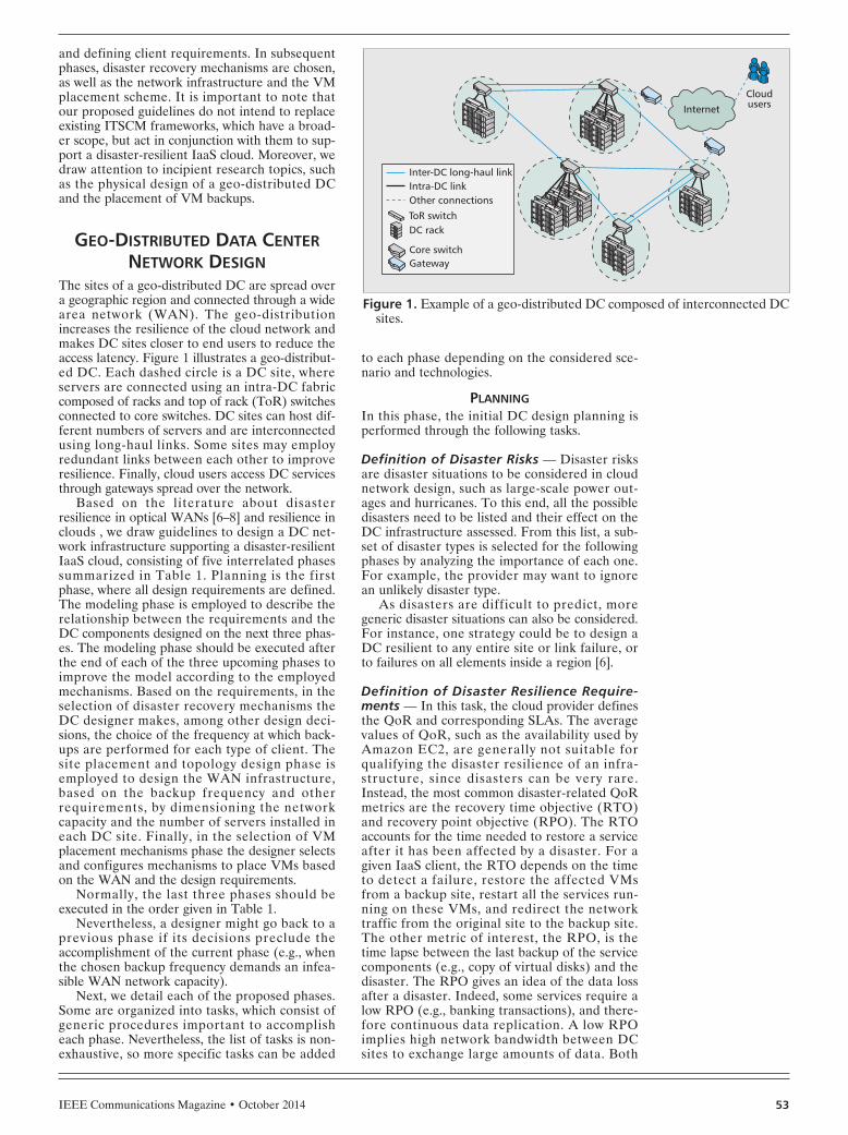
The sites of a geo-distributed DC are spread overa geographic region and connected through a widearea network (WAN). The geo-distributionincreases the resilience of the cloud network andmakes DC sites closer to end users to reduce theaccess latency. Figure 1 illustrates a geo-distribut-ed DC. Each dashed circle is a DC site, whereservers are connected using an intra-DC fabriccomposed of racks and top of rack (ToR) switchesconnected to core switches. DC sites can host dif-ferent numbers of servers and are interconnectedusing long-haul links. Some sites may employredundant links between each other to improveresilience. Finally, cloud users access DC servicesthrough gateways spread over the network.
Based on the literature about disasterresilience in optical WANs [6–8] and resilience inclouds , we draw guidelines to design a DC net-work infrastructure supporting a disaster-resilientIaaS cloud, consisting of five interrelated phasessummarized in Table 1. Planning is the firstphase, where all design requirements are defined.The modeling phase is employed to describe therelationship between the requirements and theDC components designed on the next three phas-es. The modeling phase should be executed afterthe end of each of the three upcoming phases toimprove the model according to the employedmechanisms. Based on the requirements, in theselection of disaster recovery mechanisms theDC designer makes, among other design deci-sions, the choice of the frequency at which back-ups are performed for each type of client. Thesite placement and topology design phase isemployed to design the WAN infrastructure,based on the backup frequency and otherrequirements, by dimensioning the networkcapacity and the number of servers installed ineach DC site. Finally, in the selection of VMplacement mechanisms phase the designer selectsand configures mechanisms to place VMs basedon the WAN and the design requirements.
Normally, the last three phases should beexecuted in the order given in Table 1.
Nevertheless, a designer might go back to aprevious phase if its decisions preclude theaccomplishment of the current phase (e.g., whenthe chosen backup frequency demands an infea-sible WAN network capacity).
Next, we detail each of the proposed phases.Some are organized into tasks, which consist ofgeneric procedures important to accomplisheach phase. Nevertheless, the list of tasks is non-exhaustive, so more specific tasks can be added
to each phase depending on the considered sce-nario and technologies.
PLANNINGIn this phase, the initial DC design planning isperformed through the following tasks.
Definition of Disaster Risks — Disaster risksare disaster situations to be considered in cloudnetwork design, such as large-scale power out-ages and hurricanes. To this end, all the possibledisasters need to be listed and their effect on theDC infrastructure assessed. From this list, a sub-set of disaster types is selected for the followingphases by analyzing the importance of each one.For example, the provider may want to ignorean unlikely disaster type.
As disasters are difficult to predict, moregeneric disaster situations can also be considered.For instance, one strategy could be to design aDC resilient to any entire site or link failure, orto failures on all elements inside a region [6].
Definition of Disaster Resilience Require-ments — In this task, the cloud provider definesthe QoR and corresponding SLAs. The averagevalues of QoR, such as the availability used byAmazon EC2, are generally not suitable forqualifying the disaster resilience of an infra-structure, since disasters can be very rare.Instead, the most common disaster-related QoRmetrics are the recovery time objective (RTO)and recovery point objective (RPO). The RTOaccounts for the time needed to restore a serviceafter it has been affected by a disaster. For agiven IaaS client, the RTO depends on the timeto detect a failure, restore the affected VMsfrom a backup site, restart all the services run-ning on these VMs, and redirect the networktraffic from the original site to the backup site.The other metric of interest, the RPO, is thetime lapse between the last backup of the servicecomponents (e.g., copy of virtual disks) and thedisaster. The RPO gives an idea of the data lossafter a disaster. Indeed, some services require alow RPO (e.g., banking transactions), and there-fore continuous data replication. A low RPOimplies high network bandwidth between DCsites to exchange large amounts of data. Both
Figure 1. Example of a geo-distributed DC composed of interconnected DCsites.
CloudusersInternet
Inter-DC long-haul linkIntra-DC linkOther connections
ToR switchDC rack
Core switchGateway
DESOUZACOUTO_LAYOUT.qxp_Layout 9/25/14 1:32 PM Page 53
IEEE Communications Magazine • October 201454
RTO and RPO levels can span from a few min-utes to several hours [1].
Definition of Design Constraints — The designconstraints are aspects to be considered regardlessof the disaster resilience. Among the most impor-tant constraints are the QoS requirements, whichinfluence the quality of experience (QoE). Accord-ing to International Telecommunication Union —Telecommunication Standards (ITU-T) Recom-mendation P.10, QoE is “the overall acceptabilityof an application or service, as perceived subjec-tively by the end-user” [9], meaning that the QoEdepends on all infrastructure elements, such as thenetwork and physical servers, and on external fac-tors such as the service price. Indeed, we have toensure both QoR and QoS requirements to pro-vide a good QoE. However, we need to guaranteethe QoR without compromising the QoS, sincedisaster events are rare, while QoS metrics arepermanently perceived by end users, directly orindirectly. For example, the DC geo-distribution,aiming to improve disaster resilience, increases thedistance between DC sites and may increase theservice latency, a QoS metric, when there are mul-tiple VMs running across different sites. There-fore, in this task, the cloud provider should list allof the QoS metrics to ensure that the next designsteps consider these requirements. Moreover,QoR requirements that are unrelated to disasters,such as availability, must be considered if theyappear in the SLAs.
The constraints also include other factorssuch as the maximum budget to build the DC,the possible geographical sites to install the DC,and other constraints related to the site’s physi-cal capacity. As an example of the last one, theIaaS provider may need to install a minimumnumber of servers in a site according to theexpected demand of a region.
MODELINGThis phase defines models that capture the char-acteristics of the scenario defined in the plan-ning phase. Also, the model describes how the
DC components, defined in the three next designphases, affect the infrastructure characteristics(e.g., cost, QoS metrics, RPO, and RTO). Notethat this phase stitches all the design phasestogether, defining their relationships, which canvary depending on the considered scenario. Themodels defined in this phase basically take intoaccount the disaster information and networkparameters.
The disaster information gathered in theplanning phase is used to build disaster models.Disaster models for communication networkscan be deterministic, probabilistic, or based onmulti-layer networks [6]. A classical determinis-tic model is the utilization of shared risk group(SRG) sets. An SRG is a set of infrastructurecomponents susceptible to a common disastersituation. For example, considering power out-ages, an SRG is the set of DC sites served byone power plant.
In contrast, probabilistic models consider thateach component or set of components fail with agiven probability independent of zones. As disas-ters and their impact on the network are difficultto predict and are not frequent, deterministicmodels are preferable. The approach that con-siders multi-layer networks is an incipientresearch topic, which separately models failuresin each network layer. For example, a single fail-ure on the physical layer, such as cable cuts, canaffect multiple IP routes, which can thus breakseveral TCP connections. On the other hand,recovery from a cable cut can be rapidlyaddressed by lower layers, thus being unnotice-able by upper layers. Multi-layer models aremore complex and require more information onthe environment than deterministic and proba-bilistic ones.
Network parameters such as traffic distribu-tion, length of network links, and available band-width are modeled by conventional networkmodeling approaches. For example, the networkcan be modeled as a graph, where the nodes areDC sites and the edges are the links betweenthem. The edges can be weighted according toQoS parameters such as latency between DCsites. The latency could be found after runningshortest path algorithms in the graph. Graphmodels can be combined with SRG informationto capture disaster risks. In this case, the SRGsdefined in the disaster model are composed ofnodes and edges. Using graph theory, we canmeasure, for instance, which DC sites are affect-ed by each SRG. A model that captures theresilience metrics based on network parametersis still an open research issue. This model cap-tures, for example, how the increase of band-width between DC sites affects the RPO levelsoffered by the IaaS provider. In addition, themodel could describe how the network reconfig-uration and activation of backup VMs, describedin the next section, affect RTO levels.
SELECTION OFDISASTER RECOVERY MECHANISMS
In this phase, the cloud provider chooses therecovery mechanisms, which directly impact theRTO and RPO, that will perform the followingtasks.
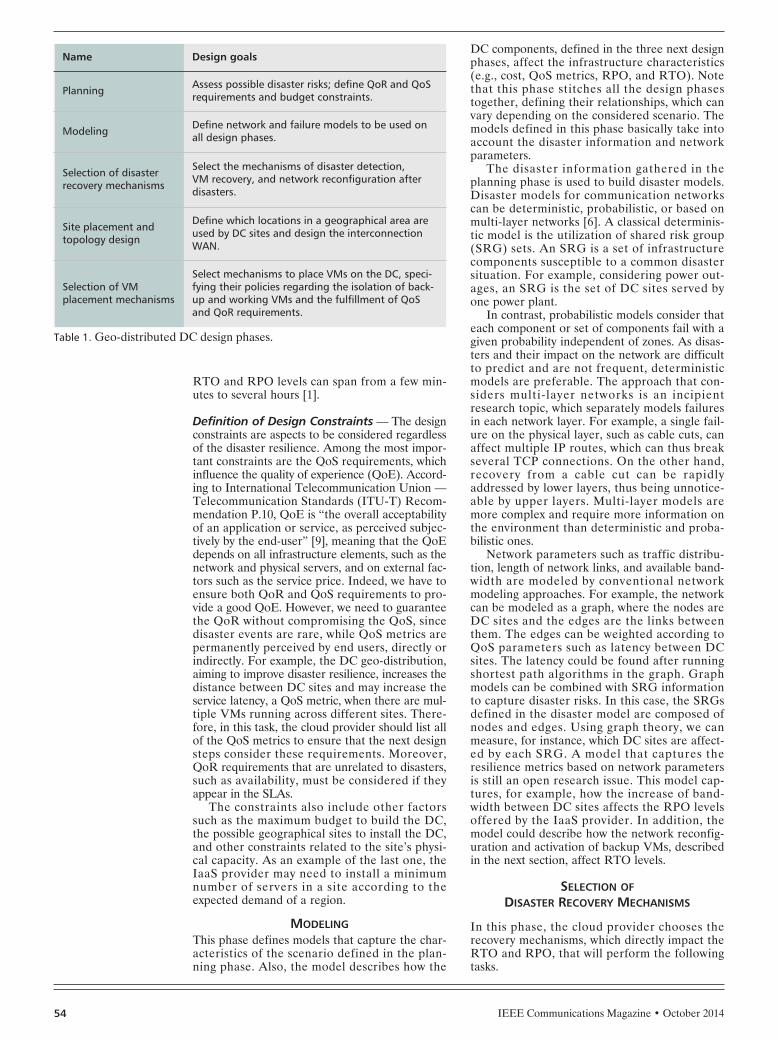
Table 1. Geo-distributed DC design phases.
Name Design goals
Planning Assess possible disaster risks; define QoR and QoSrequirements and budget constraints.
Modeling Define network and failure models to be used onall design phases.
Selection of disasterrecovery mechanisms
Select the mechanisms of disaster detection, VM recovery, and network reconfiguration afterdisasters.
Site placement andtopology design
Define which locations in a geographical area areused by DC sites and design the interconnectionWAN.
Selection of VMplacement mechanisms
Select mechanisms to place VMs on the DC, speci-fying their policies regarding the isolation of back-up and working VMs and the fulfillment of QoSand QoR requirements.
DESOUZACOUTO_LAYOUT.qxp_Layout 9/25/14 1:32 PM Page 54
IEEE Communications Magazine • October 2014 55
Selection of Disaster Detection Mecha-nisms — Despite all failure detection mecha-nisms employed in the network layers (e.g.,reaction of routing protocols), the DC mustemploy a mechanism to define when to migrateservices from their working sites to backup sites.
As the RTO depends on the reaction time toa disaster, failure detection plays an importantrole in disaster recovery. It can be done by peri-odically probing DC sites, using network alarms,and so on. Obviously, the more frequent theprobes and the network alarms, the shorter theRTO, but at the cost of more control traffic.
Selection of VM Recovery Mechanisms — Asuitable strategy to post-disaster VM recovery is touse VM snapshots [1]. A snapshot is a copy of theVM state at a given moment, which can include itsdisk, memory state, and settings. Most of the vir-tualization platforms support snapshots. Hence,the DC can maintain a snapshot of its VMs inbackup sites and activate them after a disaster.Note that this scheme forces the services runningon the VM to return to a previous state, affectingthe RPO. More frequent snapshots translate toshorter RPOs but spend more network resourcesfor snapshot transfers. Indeed, the choice of thefrequency to perform snapshots depends on theQoR classes and the defined constraints.
Selection of Network Reconfiguration Mech-anisms — When a VM starts running in anotherDC site after a disaster, the network infrastructuremust reroute the traffic destined to this VM. Thisdesign task selects adequate mechanisms to per-form network reconfiguration in the event of adisaster. IaaS providers generally employ DomainName System (DNS) services to redirect the VM’straffic when it changes physical location. Thecloud DNS server is thus responsible for replyingto DNS queries with the current VM IP address.For example, Amazon Web Services (AWS) pro-vides a DNS service called Amazon Route 53.Cloud DNS services generally rely on anycastrouting, where any node running the desired ser-vice can respond to requests, enabling simple net-work reconfiguration after disasters.3 Alternatively,providers can rely on cloud network overlay proto-cols supporting various forms of Ethernet or IPpacket encapsulation to enable flexible VM loca-tion and adequate isolation of IaaS slices [10].Note that network reconfiguration mechanismshave a high impact on the RTO, since they affectthe period for which VM network endpointsremain unreachable after a disaster.
SITE PLACEMENT AND TOPOLOGY DESIGNIn this phase, the DC inter-site WAN topology ischosen, as well as the location of each DC site.Although the intra-site local network is also aDC design decision, it is generally not concernedwith disaster resilience, since a disaster typicallycauses the failure of an entire DC site. Hence,intra-site redundancy is generally employed toachieve high DC availability but not disasterresilience [11].
DC Site Placement — This task defines whereto install DC sites in a geographic region to min-imize the impact of disasters. Moreover, the site
placement defines how many servers are installedin each DC site, and how many servers are leftto host backup VMs.
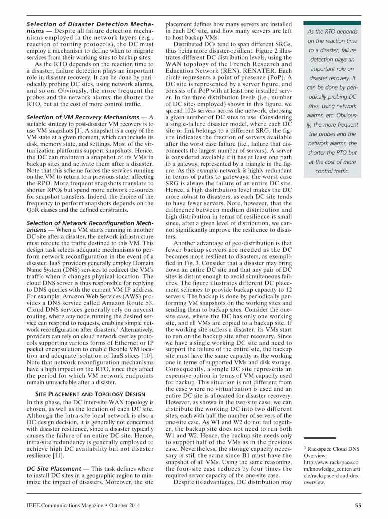
Distributed DCs tend to span different SRGs,thus being more disaster-resilient. Figure 2 illus-trates different DC distribution levels, using theWAN topology of the French Research andEducation Network (REN), RENATER. Eachcircle represents a point of presence (PoP). ADC site is represented by a server figure, andconsists of a PoP with at least one installed serv-er. In the three distribution levels (i.e., numberof DC sites employed) shown in this figure, wespread 1024 servers across the network, choosinga given number of DC sites to use. Consideringa single-failure disaster model, where each DCsite or link belongs to a different SRG, the fig-ure indicates the fraction of servers availableafter the worst case failure (i.e., failure that dis-connects the largest number of servers). A serveris considered available if it has at least one pathto a gateway, represented by a triangle in the fig-ure. As this example network is highly redundantin terms of paths to gateways, the worst caseSRG is always the failure of an entire DC site.Hence, a high distribution level makes the DCmore robust to disasters, as each DC site tendsto have fewer servers. Note, however, that thedifference between medium distribution andhigh distribution in terms of resilience is smallsince, after a given level of distribution, we can-not significantly improve the resilience to disas-ters.
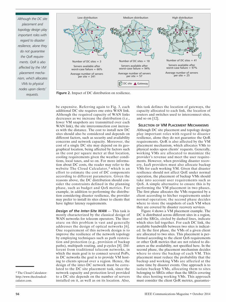
Another advantage of geo-distribution is thatfewer backup servers are needed as the DCbecomes more resilient to disasters, as exempli-fied in Fig. 3. Consider that a disaster may bringdown an entire DC site and that any pair of DCsites is distant enough to avoid simultaneous fail-ures. The figure illustrates different DC place-ment schemes to provide backup capacity to 12servers. The backup is done by periodically per-forming VM snapshots on the working sites andsending them to backup sites. Consider the one-site case, where the DC has only one workingsite, and all VMs are copied to a backup site. Ifthe working site suffers a disaster, its VMs startto run on the backup site after recovery. Sincewe have a single working DC site and need tosupport the failure of the entire site, the backupsite must have the same capacity as the workingone in terms of supported VMs and disk storage.Consequently, a single DC site represents anexpensive option in terms of VM capacity usedfor backup. This situation is not different fromthe case where no virtualization is used and anentire DC site is allocated for disaster recovery.However, as shown in the two-site case, we candistribute the working DC into two differentsites, each with half the number of servers of theone-site case. As W1 and W2 do not fail togeth-er, the backup site does not need to run bothW1 and W2. Hence, the backup site needs onlyto support half of the VMs as in the previouscase. Nevertheless, the storage capacity neces-sary is still the same since B1 must have thesnapshot of all VMs. Using the same reasoning,the four-site case reduces by four times therequired server capacity of the one-site case.
Despite its advantages, DC distribution may
3 Rackspace Cloud DNSOverview:http://www.rackspace.com/knowledge_center/article/rackspace-cloud-dns-overview.
As the RTO depends
on the reaction time
to a disaster, failure
detection plays an
important role on
disaster recovery. It
can be done by peri-
odically probing DC
sites, using network
alarms, etc. Obvious-
ly, the more frequent
the probes and the
network alarms, the
shorter the RTO but
at the cost of more
control traffic.
DESOUZACOUTO_LAYOUT.qxp_Layout 9/25/14 1:32 PM Page 55
IEEE Communications Magazine • October 201456
be expensive. Referring again to Fig. 3, eachadditional DC site requires one extra WAN link.Although the required capacity of WAN linksdecreases as we increase the distribution (i.e.,fewer VM snapshots are transmitted over eachWAN link), the site interconnection cost increas-es with the distance. The cost to install new DCsites should also be considered and depends ondifferent factors, such as security and availabilityconcerns and network capacity. Moreover, thecost of a single DC site may depend on its geo-graphical location, being affected by factors suchas the cost per square meter at that location,cooling requirements given the weather condi-tions, local taxes, and so on. For more informa-tion about DC costs, the reader may refer to thewebsite The Cloud Calculator,4 which is aneffort to estimate the cost of DC componentsaccording to different parameters. Given thereasons above, the DC distribution should con-sider the constraints defined in the planningphase, such as budget and QoS metrics. Forexample, in addition to performing the distribu-tion considering disaster resilience, the providermay prefer to install its sites closer to clients thathave tighter latency requirements.
Design of the Inter-Site WAN — This task ismostly characterized by the classical design ofWAN networks for telecom operators. The liter-ature on this problem is vast and generallyaddresses the design of optical networks [6].One requirement of this network design is toimprove the resilience of the network topologyby employing techniques such as path restora-tion and protection (e.g., provision of backuppaths), multipath routing, and p-cycles [8]. Dif-ferent from traditional telecom networks, inwhich the main goal is to connect several PoPs,in DC networks the goal is to provide VM host-ing to clients spread over a region. Hence, thedesign of the inter-DC network must be corre-lated to the DC site placement task, since thenetwork capacity and protection level providedto a DC site depends on the number of serversinstalled on it, as well as on its location. Also,
this task defines the location of gateways, thecapacity allocated to each link, the location ofrouters and switches used to interconnect sites,and so on [12].
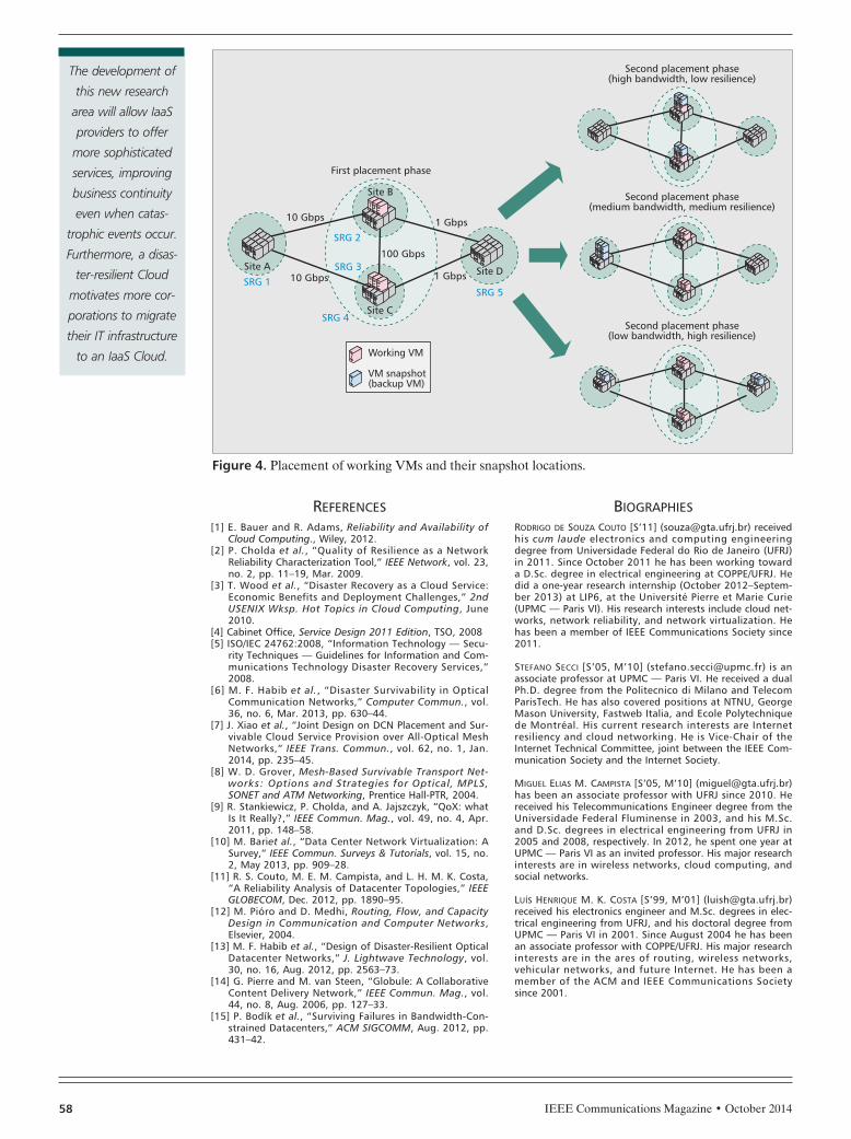
SELECTION OF VM PLACEMENT MECHANISMSAlthough DC site placement and topology designplay important roles with regard to disasterresilience, alone they do not guarantee the QoRrequirements. QoR is also affected by the VMplacement mechanism, which allocates VMs tophysical nodes upon clients’ requests. Generally,working VMs are allocated to maximize theprovider’s revenue and meet the user require-ments. However, when providing disaster recov-ery, IaaS providers must also allocate backupVMs for each working VM. Given that disasterresilience should not affect QoE under normaloperation, the placement of backup VMs shouldtake into account user requirements such asQoS. A simple alternative to ensure this is byperforming the VM placement in two phases.The first phase allocates the VMs requested by aclient according to his/her requirements undernormal operation; the second phase decideswhere to store the snapshots of each VM whenthey are covered by disaster recovery services.
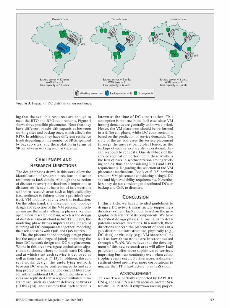
Figure 4 shows a VM placement example. TheDC is distributed across different sites in a region,and the SRGs, circled by dashed lines, indicatewhich sites fail together. For each DC link, theavailable bandwidth between two sites is indicat-ed. In the first phase, the VMs of a given clientare allocated to two sites. This placement is per-formed according to the client QoS requirementsor other QoR metrics that are not related to dis-asters as the availability, not specified here. In thesecond phase, the placement mechanism decideswhere to store the backup of each VM. Thisplacement must reduce the probability that thebackup and working VMs are affected at thesame time by disaster events. One approach is toisolate backup VMs, allocating them to sitesbelonging to SRGs other than the SRGs coveringthe sites hosting working VMs. This approachmust consider the client QoR metrics, guarantee-
4 The Cloud Calculator:http://www.thecloudcal-culator.com.
Figure 2. Impact of DC distribution on resilience.
Number of DC sites = 18
Servers available afterworst-case failure = 94%
Average number of serversper site = 57
Number of DC sites = 3
Servers available afterworst-case failure = 66%
Average number of serversper site = 341
Number of DC sites = 41
Servers available afterworst-case failure = 97%
Average number of serversper site = 25
Medium distributionLow distribution High distribution
DC site Gateway
Although the DC site
placement and
topology design play
important roles with
regard to disaster
resilience, alone they
do not guarantee
the QoR require-
ments. QoR is also
affected by the VM
placement mecha-
nism, which allocates
VMs to physical
nodes upon clients’
requests.
DESOUZACOUTO_LAYOUT.qxp_Layout 9/25/14 1:32 PM Page 56
IEEE Communications Magazine • October 2014 57
ing that the available resources are enough tomeet the RTO and RPO requirements. Figure 4shows three possible placements. Note that theyhave different bandwidth capacities betweenworking sites and backup ones, which affects theRPO. In addition, they have different resiliencelevels depending on the number of SRGs spannedby backup sites, and the isolation in terms ofSRGs between working and backup sites.
CHALLENGES ANDRESEARCH DIRECTIONS
The design phases drawn in this work allow theidentification of research directions in disasterresilience to IaaS clouds. Although the selectionof disaster recovery mechanisms is important todisaster resilience, it has a lot of intersectionswith other research areas such as high availability(i.e., resilience to failures under a provider’s con-trol), VM mobility, and network virtualization.On the other hand, site placement and topologydesign and selection of the VM placement mech-anisms are the most challenging phases since theyopen a new research domain, which is the designof disaster-resilient cloud networks. Finally, themodeling phase brings important challenges ofstitching all DC components together, modelingtheir relationships with QoR and QoS metrics.
The site placement and topology design phasehas the major challenge of jointly optimizing theinter-DC network design and DC site placement.Works in this area investigate optimization algo-rithms to choose where to install each DC site,and at which sites each service is deployed aswell as their backups [7, 13]. In addition, the cur-rent works design the underlying networkbetween DC sites by configuring paths and set-ting protection schemes. The current literatureconsiders traditional DC distribution where ser-vices are replicated across a geo-distributed infra-structure, such as content delivery networks(CDNs) [14], and assumes that each service is
known at the time of DC construction. Thisassumption is not true in the IaaS case, since VMhosting demands are generally unknown a priori.Hence, the VM placement should be performedin a different phase, while DC construction isbased on the prediction of service demands. Thestate of the art addresses the service placementthrough the anycast principle. Hence, as thebackups of each service are also operational, theycan respond to requests. One drawback of theservice replication performed in these works isthe lack of backup synchronization among work-ing copies, thus not considering RTO and RPOrequirements. Regarding the selection of the VMplacement mechanisms, Bodík et al. [15] performresilient VM placement considering a single DCsite and high availability requirements. Neverthe-less, they do not consider geo-distributed DCs orbackup and QoR to disasters.
CONCLUSIONIn this article, we have provided guidelines todesign a DC network infrastructure supporting adisaster-resilient IaaS cloud, based on the geo-graphic redundancy of its components. We havedescribed design phases, allowing us to drawpotential research directions. In a nutshell, thesedirections concern the placement of nodes in ageo-distributed infrastructure, physically (e.g.,DC sites) or virtually (e.g., VM snapshots), aswell as how these nodes are interconnectedthrough a WAN. We believe that the develop-ment of this new research area will allow IaaSproviders to offer more sophisticated services,improving business continuity even when catas-trophic events occur. Furthermore, a disaster-resilient cloud motivates more corporations tomigrate their IT infrastructure to an IaaS cloud.
ACKNOWLEDGMENTThis work was partially supported by FAPERJ,CNPq, and CAPES research agencies, and the Sys-tematic FUI 15 RAVIR (http://www.ravir.io) project.
Figure 3. Impact of DC distribution on resilience.
Working server unit Backup server unit Storage unit
Backup server = 6 unitsWAN links = 2
Link capacity = 6 units
Backup server = 12 unitsWAN links = 1
Link capacity = 12 units
Backup server = 3 unitsWAN links = 4
Link capacity = 3 units
Two-site caseOne-site case Four-site case
W1
W1
B1
W1W3
W4
W2
W2
DESOUZACOUTO_LAYOUT.qxp_Layout 9/25/14 1:32 PM Page 57
IEEE Communications Magazine • October 201458
REFERENCES[1] E. Bauer and R. Adams, Reliability and Availability of
Cloud Computing., Wiley, 2012.[2] P. Cholda et al., “Quality of Resilience as a Network
Reliability Characterization Tool,” IEEE Network, vol. 23,no. 2, pp. 11–19, Mar. 2009.
[3] T. Wood et al., “Disaster Recovery as a Cloud Service:Economic Benefits and Deployment Challenges,” 2ndUSENIX Wksp. Hot Topics in Cloud Computing, June2010.
[4] Cabinet Office, Service Design 2011 Edition, TSO, 2008[5] ISO/IEC 24762:2008, “Information Technology — Secu-
rity Techniques — Guidelines for Information and Com-munications Technology Disaster Recovery Services,”2008.
[6] M. F. Habib et al., “Disaster Survivability in OpticalCommunication Networks,” Computer Commun., vol.36, no. 6, Mar. 2013, pp. 630–44.
[7] J. Xiao et al., “Joint Design on DCN Placement and Sur-vivable Cloud Service Provision over All-Optical MeshNetworks,” IEEE Trans. Commun., vol. 62, no. 1, Jan.2014, pp. 235–45.
[8] W. D. Grover, Mesh-Based Survivable Transport Net-works: Options and Strategies for Optical, MPLS,SONET and ATM Networking, Prentice Hall-PTR, 2004.
[9] R. Stankiewicz, P. Cholda, and A. Jajszczyk, “QoX: whatIs It Really?,” IEEE Commun. Mag., vol. 49, no. 4, Apr.2011, pp. 148–58.
[10] M. Bariet al., “Data Center Network Virtualization: ASurvey,” IEEE Commun. Surveys & Tutorials, vol. 15, no.2, May 2013, pp. 909–28.
[11] R. S. Couto, M. E. M. Campista, and L. H. M. K. Costa,“A Reliability Analysis of Datacenter Topologies,” IEEEGLOBECOM, Dec. 2012, pp. 1890–95.
[12] M. Pióro and D. Medhi, Routing, Flow, and CapacityDesign in Communication and Computer Networks,Elsevier, 2004.
[13] M. F. Habib et al., “Design of Disaster-Resilient OpticalDatacenter Networks,” J. Lightwave Technology, vol.30, no. 16, Aug. 2012, pp. 2563–73.
[14] G. Pierre and M. van Steen, “Globule: A CollaborativeContent Delivery Network,” IEEE Commun. Mag., vol.44, no. 8, Aug. 2006, pp. 127–33.
[15] P. Bodík et al., “Surviving Failures in Bandwidth-Con-strained Datacenters,” ACM SIGCOMM, Aug. 2012, pp.431–42.
BIOGRAPHIESRODRIGO DE SOUZA COUTO [S’11] ([email protected]) receivedhis cum laude electronics and computing engineeringdegree from Universidade Federal do Rio de Janeiro (UFRJ)in 2011. Since October 2011 he has been working towarda D.Sc. degree in electrical engineering at COPPE/UFRJ. Hedid a one-year research internship (October 2012–Septem-ber 2013) at LIP6, at the Université Pierre et Marie Curie(UPMC — Paris VI). His research interests include cloud net-works, network reliability, and network virtualization. Hehas been a member of IEEE Communications Society since2011.
STEFANO SECCI [S’05, M’10] ([email protected]) is anassociate professor at UPMC — Paris VI. He received a dualPh.D. degree from the Politecnico di Milano and TelecomParisTech. He has also covered positions at NTNU, GeorgeMason University, Fastweb Italia, and Ecole Polytechniquede Montréal. His current research interests are Internetresiliency and cloud networking. He is Vice-Chair of theInternet Technical Committee, joint between the IEEE Com-munication Society and the Internet Society.
MIGUEL ELIAS M. CAMPISTA [S’05, M’10] ([email protected])has been an associate professor with UFRJ since 2010. Hereceived his Telecommunications Engineer degree from theUniversidade Federal Fluminense in 2003, and his M.Sc.and D.Sc. degrees in electrical engineering from UFRJ in2005 and 2008, respectively. In 2012, he spent one year atUPMC — Paris VI as an invited professor. His major researchinterests are in wireless networks, cloud computing, andsocial networks.
LUÍS HENRIQUE M. K. COSTA [S’99, M’01] ([email protected])received his electronics engineer and M.Sc. degrees in elec-trical engineering from UFRJ, and his doctoral degree fromUPMC — Paris VI in 2001. Since August 2004 he has beenan associate professor with COPPE/UFRJ. His major researchinterests are in the ares of routing, wireless networks,vehicular networks, and future Internet. He has been amember of the ACM and IEEE Communications Societysince 2001.
Figure 4. Placement of working VMs and their snapshot locations.
Second placement phase(high bandwidth, low resilience)
Second placement phase(medium bandwidth, medium resilience)
Second placement phase(low bandwidth, high resilience)
First placement phase
Site A
Site B
SRG 2
SRG 3
SRG 4
SRG 1SRG 5
Site C
Site D1 Gbps
1 Gbps
100 Gbps
10 Gbps
10 Gbps
Working VM
VM snapshot(backup VM)
The development of
this new research
area will allow IaaS
providers to offer
more sophisticated
services, improving
business continuity
even when catas-
trophic events occur.
Furthermore, a disas-
ter-resilient Cloud
motivates more cor-
porations to migrate
their IT infrastructure
to an IaaS Cloud.
DESOUZACOUTO_LAYOUT.qxp_Layout 9/25/14 1:32 PM Page 58