Network Camera Camera User Manual.pdf · odor or noise rising from the IPC. ... automatically...
60
Network Camera User Manual Version:8.1.45.4
Transcript of Network Camera Camera User Manual.pdf · odor or noise rising from the IPC. ... automatically...

Network Camera
User Manual
Version:8.1.45.4

2
Statement Thank you for purchasing our product. If there are any questions or requests, please do not
hesitate to contact the dealer.
This manual applies to network camera.
This manual may contain several technical incorrect places or printing errors, and the content
is subject to change without notice. The updates will be added to the new version of this
manual. We will readily improve or update the products or procedures described in the
manual.
Legal Disclaimer Should any reasons below cause the product destroyed or service stop, we will assume
no responsibility for your or third party’s personal injury and property loss: ① No
installation or use according to instruction strictly. ② For sake of state-building
maintenance or public interest. ③ Cases of force majeure. ④ Your personal or third
party reasons. (Include no limitation use of third party’s products, software or
components)
Our company has never guaranteed the products for improper or illegal purposes and
uses. This product cannot be used as medical & safety devices or other applications that
will cause danger or injury. And loss or responsibility caused by above uses, you must
bear it by yourself.
With correct installation and use, this product can detect the illegal intrusion, but it can
not avoid accidents and personal injury or property damage due to these accidents.
Please be on the alert in your daily life, reinforce your safety awareness.
Our company assumes no responsibility for any indirect or occasional or special or
punitive damages, request, property damage or any loss of data or file. Within the max
scope of law allowed, our company’s compensation is no more than the products
amount you paid.
Safety Instruction
This manual is intended to ensure that user can use the product properly without danger or
any property loss. Please read it carefully and take care of it for further reference. Precaution
measures are divided into “warnings” and “cautions” as below:
Warnings: Neglecting any of the warnings may cause death or serious injury.
Cautions: Neglecting any of the cautions may cause injury or equipment damage.

3
Warning Electrical safety regulations of the nation and the region must be strictly followed during
installation or use.
Please use the matched power adapter from standard company.
Do not connect multiple IPCs with one single power adapter (Overload for adapter may
lead to over-heat or fire hazard.
Shut down the power while connecting or dismounting the device. Do not operate with
power on.
The device should be firmly fixed when installed onto the wall or beneath the ceiling.
Shut down the power and unplug the power cable immediately when there is smoke,
odor or noise rising from the IPC. Then contact the dealer or service center.
Please contact the local dealer or latest service center when IPC works abnormally. Do
not attempt to disassemble or modify the device yourself. (We shall shoulder no
responsibility for problems caused by unauthorized repair or maintenance.
Cautions Make sure the power supply voltage is correct before using the camera.
Do not drop the camera or subject it to physical shock.
Do not touch sensor modules with fingers. If cleaning is necessary, use a clean cloth
with a bit of ethanol and wipe it gently. If the camera will not be used for an extended
period of time, put on the lens cap to protect the sensor from dirt.
Do not aim the camera lens at the strong light such as sun or incandescent lamp. The
strong light can cause fatal damage to the camera.
The sensor may be burned out by a laser beam, so when any laser equipment is being
used, make sure that the surface of the sensor not be exposed to the laser beam.
Do not place the camera in extremely hot, cold temperatures (the operating temperature
should be between -30°C ~ 60°C), dusty or damp environment, and do not expose it to
high electromagnetic radiation.
To avoid heat accumulation, good ventilation is required for a proper operating
environment.
Keep the camera away from water and any liquid.
While shipping, the camera should be packed in its original packing.
Improper use or replacement of the battery may result in hazard of explosion. Please
use the manufacturer recommended battery type.

4
Table of Contents
STATEMENT ............................................................................................................................................. 2
CHAPTER 1 PRODUCT INTRODUCTION ..................................................................................................... 6
1.1 PRODUCT MANUAL ............................................................................................................................ 6
1.2 PRODUCT FEATURES........................................................................................................................... 6
CHAPTER 2 OPERATING INSTRUCTIONS ................................................................................................... 7
2.1 NETWORK CONNECTION .................................................................................................................... 7
2.1.1 WIRED NETWORK CONNECTION ................................................................................................................. 7 2.1.2 WIRELESS INTERNET ACCESS ...................................................................................................................... 7
2.2 DETECTING AND CHANGING THE IP ADDRESS .................................................................................... 8
2.3 SETTING THE NETWORK CAMERA OVER THE WAN ............................................................................. 9
2.3.1 STATIC IP CONNECTION ............................................................................................................................ 9 2.3.2 DYNAMIC IP CONNECTION ........................................................................................................................ 9
CHAPTER 3 ACCESS TO THE IPC BY CLIENT SOFTWARE ........................................................................... 11
CHAPTER 4 ACCESS TO THE IPC BY WEB CLIENT ..................................................................................... 12
4.1 PREPARATION BEFORE INSTALL PLUGIN ........................................................................................... 12
4.2 INSTALL THE HSWEBPLUGIN.EXE CONTROLS .................................................................................... 12
4.3. INTERFACE OPERATIONS AND USAGE:............................................................................................. 15
4.3.1 LOGIN ................................................................................................................................................. 15 4.3.2 CHANGE PASSWORD .............................................................................................................................. 16 4.3.3 EXIT SYSTEM ........................................................................................................................................ 17
4.4 MAIN INTERFACE DESCRIPTION ....................................................................................................... 17
CHAPTER 5 LIVE PREVIEW ...................................................................................................................... 18
5.1 LIVE PREVIEW .................................................................................................................................. 18
5.2 CAMERA SETTINGS PTZ, ZOOM, CRUISE ........................................................................................... 20
CHAPTER 6 PLAYBACK ............................................................................................................................ 23
CHAPTER 7 CONFIGURATION ................................................................................................................. 25
7.1 LOCAL CONFIGURATION ................................................................................................................... 25
7.2 SYSTEM ............................................................................................................................................ 26
7.2.1 SYSTEM CONFIGURATION ........................................................................................................................ 26 7.2.2 SCHEDULED REBOOT .............................................................................................................................. 29 7.2.3 LOG SEARCH ........................................................................................................................................ 29 7.2.4 SECURITY ............................................................................................................................................. 30 7.2.5 SD CARD ............................................................................................................................................. 32
7.3 NETWORK ........................................................................................................................................ 33
7.3.1 BASIC SETUP ........................................................................................................................................ 33 7.3.2 ADVANCE SETUP ................................................................................................................................... 35
7.4 VIDEO .............................................................................................................................................. 41
7.4.1 VIDEO ................................................................................................................................................. 41 7.4.2 AUDIO ................................................................................................................................................ 42
7.5 IMAGE.............................................................................................................................................. 42
7.5.1 IMAGE ................................................................................................................................................ 42

5
7.5.2 OSD .................................................................................................................................................. 45
7.6 EVENTS ............................................................................................................................................ 46
CHAPTER 8 APP CLIENT ....................................................................................................................... 54
8.1 INSTALLATION & REGISTER ............................................................................................................... 54
8.2 ADD DEVICE ..................................................................................................................................... 54
8.3 LIVE PREVIEW .................................................................................................................................. 55
8.4 PLAYBACK ........................................................................................................................................ 57
CHAPTER 9 FREQUENTLY ASKED QUESTIONS ......................................................................................... 60

6
Chapter 1 Product Introduction
1.1 Product Manual Network camera is integrated video and audio acquisition, intelligent coding and network transmission and other functions of digital monitoring products. Using embedded operating system and high-performance hardware processing platform, with high stability and reliability to meet the diverse needs of the industry. Network camera based on Ethernet control, image compression can be achieved through the network and transmitted to different users. Network camera support TCP / IP, UDP, HTTP, HTTPS, FTP, DHCP, DNS, DDNS, RTP, RTSP, RTCP, NTP, SMTP, SNMP and other network communication protocols; support ONVIF2.4, CGI, mainstream manufacturers agreement and other Internet protocols. You can use the browser or client software to control the network camera, and through the browser to set the network camera parameters, such as system parameter settings, OSD display settings and other parameters; through the browser or client software configuration can also achieve motion detection, Abnormal alarm and other intelligent functions, the specific function parameters, please take the actual equipment.
1.2 Product Features This section introduces the webcam from the product features, allowing you to become more familiar with and familiar with webcams. Video and capture functions The network camera supports video recording and capture function. Mirror function The network camera supports video horizontal, vertical, horizontal vertical flip function. Day and night mode adjustment The network camera supports LDR automatic, daytime, night and video auto four modes. In the LDR automatic mode, the camera automatically switches mode according to ambient light changes; the picture is color in daytime mode; the picture is black and white in night mode; in video auto mode, the video image changes with the ambient light. Electronic shutter function Low-light electronic shutter When you are in a low-light environment, you can set the low-light electronic shutter function, then the network camera shutter automatically slows down, by extending the exposure time to get brighter, less noise images. Backlight compensation or Wide dynamic function When the backlight compensation function is turned on, the network camera will automatically adjust the brightness of the target area to ensure that the screen of the target area is clearly visible. When wide dynamic, the network camera automatically balances the brightest and darkest screens in the monitor screen to enhance the dynamic range of the overall picture in order to see more monitor picture details. Event function The network camera event includes motion detection, occlusion alarm, video loss, alarm input / output and abnormal alarm. User management You can manage multiple different users through the system administrator "admin" user and configure a different level for each user. Video playback Support the TF card or SD card to support the network camera to support video playback, query and playback card recording. WIFI function With WIFI function camera, support wireless connection router WIFI hotspot or with a hot wireless NVR. With WIFI hotspot camera, support mobile phone connected camera WIFI hotspots, preview IPC real-time video. PTZ function With PTZ function camera support lens zoom, aperture control, PTZ control and cruise

7
settings and other functions. Cloud storage function The network camera supports the cloud storage function, which stores the device motion detection alarm information on the cloud server.
Note Network camera above product features depending on the specific model, please take
the actual product technical parameters shall prevail.
Chapter 2 Operating instructions
2.1 Network Connection
Cautions
If you have access to the Internet at your own risk, including but not limited to the product may be subject to network attacks, hacker attacks, virus infection, the company does not cause the product abnormalities, information disclosure and other issues, but the
company will In time to provide you with product-related technical support.
To view and configure the network camera over the network, you need to connect the IP camera to your computer and install IPC Search or VMS software to search and change the IP of your network camera. And then through the browser to preview and related functions of the configuration.
2.1.1 Wired network connection Before configuring the network camera, make sure that the IP camera is connected to the computer and that you can access the network camera you want to set up. There are two types of wired connections; you can directly connect the network camera to the computer with a network cable as shown in Figure 2-1:
Figure 2-1 Set network camera over the LAN via a switch or a router as shown in Figure 2-2:
Figure 2-2
2.1.2 Wireless internet access Some network cameras support wireless network transmission, in the wireless network environment, the network camera and computer connection as shown in Figure 2-3.

8
Figure 2-3
2.2 Detecting and Changing the IP Address To access the IP address of a network camera, proceed as follows:
Step 1: Search IPC IP address. Using the IP Search tool, you can search all the online cameras in the LAN and display
the IP, MAC address, version, port and other information of the camera, as shown in Figure2-4:
Figure 2-4
Use the VMS client software to search for online devices. For details, refer to the
VMS User Manual.
Step 2:Change the IP address and sub net mask to the same sub net as that of your
computer.
In the IP search tool to select the device to modify the IP, right side of the interface
directly modify the IP and gateway, enter the password, and click "Modify".
Step 3:Open the browser to enter the IP address of the camera, enter the web login
screen.

9
Note: The default IP address is 192.168.1.168 and the port number is 80. The default user
name is admin, and password is admin. And you are highly recommended change the initial password after your first login.
For accessing the network camera from different sub nets, please set the gateway for the network camera after you logged in. For detailed information, please refer to Section 4.4.3.1 Configuring TCP/IP Settings.
2.3 Setting the Network Camera over the WAN This section explains how to connect the network camera to the WAN with a static IP or a dynamic IP.
2.3.1 Static IP Connection Before you start: Please apply a static IP from an ISP (Internet Service Provider). With the static IP address, you can connect the network camera via a router or connect it to the WAN directly.
The router is connected to the network camera as shown in Figure 2-5:
Figure 2-5
Specific steps are as follows:
Step 1: Connect the network camera to the router. Step 2: Assign a LAN IP address, the sub net mask and the gateway. For details, please
refer to 7.3.1.
Step 3: Save the static IP in the router.
Step 4: Set port mapping, e.g., 80, 8000, and 554 ports. The steps for port mapping vary
according to the different routers. Please call the router manufacturer for assistance with port mapping.
Step 5: Visit the network camera through a web browser or the client software over the
internet.
Directly through the static IP connection IPC, as shown in Figure 2-6:
Figure 2-6
You can also save the static IP in the camera and directly connect it to the internet without using a router. For details, please refer to 7.3.1.
2.3.2 Dynamic IP Connection Before you start:
Please apply a dynamic IP from an ISP. With the dynamic IP address, you can connect the network camera to a modem or a router.
The router is connected to the network camera
Specific steps are as follows:
Step 1: Connect the network camera to the router.

10
Step 2: Assign a LAN IP address, the sub net mask and the gateway. For details, please
refer to 7.3.1.
Step 3:In the router, set the PPPoE user name, password and confirm the password.
Step 4: Set port mapping, e.g., 80, 8000, and 554 ports. The steps for port mapping vary
according to the different routers. Please call the router manufacturer for assistance with port mapping.
Step 5:Apply a domain name from a domain name provider.
Step 6:Configure the DDNS settings in the setting interface of the router.
Step 7:Visit the camera via the applied domain name.
Note: The obtained IP address is dynamically assigned via PPPoE, so the IP address always
changes after rebooting the camera. To solve the inconvenience of the dynamic IP, you need to get a domain name from the DDNS provider (E.g. DynDns.com). Please follow the steps below for normal domain name resolution and private domain name resolution to solve the problem.
Normal Domain Name Resolution as shown in Figure 2-7:
Figure 2-7
Specific steps are as follows:
Step 1: Apply a domain name from a domain name provider. Step 2: Configure the DDNS settings in the DDNS Settings interface of the network camera. For details, please refer to 7.3.2. Step 3: Visit the camera via the applied domain name.
Private Domain Name Resolution, as shown in Figure 2-8:
Figure 2-8
Specific steps are as follows:
Step 1: Install and run the IP Server software in a computer with a static IP. Step 2: Access the network camera through the LAN with a web browser or the client software.

11
Step 3: Enable DDNS and select IP Server as the protocol type. For details, please refer to 7.3.2.
Chapter 3 Access to the IPC by Client Software The product CD contains the VMSLite client software. You can view the live video and manage the camera with the software. Follow the installation prompts to install the software. The control panel and live view interface of VMSLite client software are shown as show in Figure 3-1.
Figure 3-1
Note: For detailed information about the software, please refer to the user manual of the
VMSLite Client Software.

12
Chapter 4 Access to the IPC by Web Client
4.1 Preparation before install plugin
In ensuring the IPC and the current user's computer after completion of all the hardware
connection and power equipment normal, open the computer, run ping the IP address of
the IPC (Note: the IP address of the IPC in LAN must be unique). Such as IPC IP for
192.168.1.168, run ping 192.168.1.168. If there is a response to the IPC as shown in
Figure 4.-1, indicating that the network connection is normal, you can download the
plug-in.
Figure 4-1
4.2 Install the HsWebplugin.exe Controls
Note:
If you have already modified the IP address of your network camera, please log in
with the new IP address.
Please open the browser and input the IP address of IPC in the address bar. (For the first
time to use the default address is: http://192.168.1.168), you will be prompted to download
information, as show in Figure 4-2:

13
Figure 4-2
Click to download and you can choose "Run" or save directly the
installation。 Click” Next” to complete the installation as shown in Figure 4-3 (1, 2, 3, 4, 5,
and 6).
Figure 4-3(1)
Figure 4-3(2)

14
Figure 4-3(3)
Figure 4-3(4)
Figure 4-3(5)

15
Figure 4-3(6)
Click "Finish” returning to the page.
Notice
If the system prompt "installation failure", please uncheck the "cancel protection mode" in
the setting safety of "Internet options" and enter the "custom level" ActiveX control
Settings as show in Figure 4-4, and reinstall HsWebplugin.exe after save settings.
Figure 4-4
4.3. Interface operations and Usage:
4.3.1 Login
After installing the plug-in, refresh the browser interface; enter the login screen as shown

16
in Figure 4-5:
Figure 4-5
When you log in for the first time, enter the default user name: admin, password: admin,
select the system language (currently supported in Simplified Chinese, Simplified Chinese,
English, Russian, Korean, Polish, French, Japanese, Spanish, Portuguese , Italian,
Hebrew, Turkish, Bulgarian, Persian, German, Dutch, Czech).
4.3.2 Change password
After successful login, the interface prompts to change the password, as shown in Figure
4-6:
Figure 4-6
For the account security recommendations click "modify immediately", enter the user
management interface to modify the password, as shown in Figure 4-7:

17
Figure 4-7
To change your password, follow these steps:
Step 1: Enter the new password in the Password and Confirm Password fields;
Step 2: Fill in the security issues as needed, this item is optional, may not fill;
Step 3: Click "Save" to complete the password modification, the interface will
automatically jump to the login interface.
Note:
When the IPC password for the initial password "admin", each login will prompt to
change the password, please change the password and set a high-intensity
password after login.
4.3.3 Exit System
When you enter the network camera main interface, you can click the upper right corner of
the " " safe exit system.
4.4 Main interface description
18
In the IPC main interface, you can preview real-time video, playback, configuration and
PTZ control and other functions, the interface shown in Figure 4-8:
Figure 4-8
Live View: For IPC monitoring screen preview, you can switch the code stream
preview, preview can also be achieved video, capture, electronic zoom and other
functions.
Playback:Select the time or video type to find the device TF card in the video and
playback.
Configuration: Click into the IPC configuration interface for system configuration and
function configuration.
PTZ Control: Used to set the PTZ preset point, cruise line and PTZ rotation direction
preview real-time video and so on.
Note:
Network camera main interface layout function and other information, please take the
actual equipment function prevail.
Chapter 5 Live preview
5.1 Live preview
Click " " to enter the IPC preview interface, as shown in Figure 5-1:

19
Figure 5-1
【switching window size】In the real-time preview interface on the top left of the preview
ratio option, click "4: 3", "16: 9", "X1", "full screen" to switch the video preview scale.
【switching option】In the upper left of the real-time preview interface, there is a stream
switching option. Click "Main Stream", "Sub Stream" and "Triple Stream" to switch preview
video stream.
The preview interface operation buttons are shown in Table 5-1.
Icon Description
The window size is 4:3.
The preview screen is displayed in its original size.
The window size is 16:9.
Self-adaptive window size.
Main Stream/Sub
Stream/Tri-stream
To switch the real-time preview stream, take the actual function of
the device.
/ Start/Stop live view.
Manually start/stop recording.
Manually capture the picture.
Turn on / off the electronic zoom function, turn on the electronic
zoom function, in the preview image, hold down the left mouse
button to select the electronic zoom area, the interface shows the

20
region to enlarge the image
Turn on/off Sound.
Open / Close talk back
Table 5-1
5.2 Camera settings PTZ, zoom, cruise
Click " " on the right side of the window to display the PTZ control interface. Click " "
to hide the PTZ control interface, where you can set the direction of the PTZ rotation of the
camera, Zoom in / out, focus - / focus +, one-key focus, lens initialization, cruise, as shown
in Figure 5-2:
Figure 5-2
The PTZ control menu is shown in Figure 5-3 below:

21
Figure 5-3
The PTZ control interface operation buttons are shown in Table 5-2 below.
按 钮 说 明
Long press the arrow keys to control the horizontal and vertical
direction, such as vertical rotation. (Note: one of the bolt can
only rotate horizontally, does not support vertical rotation).
Click " ", the network camera will continue to rotate
horizontally, then the button will turn red; then click once, then
stop turning.
"Zoom-" and "Zoom +".
When you hold down the " ", the lens closer, the scene
zoom; hold down the " ", the lens away, the scene becomes
smaller.
"Focus-" and "Focus +".
In manual focus mode, adjust the " " and " " keys to
make the objects within the scene clear.
One Key Focus.
Init Camera.
Adjust the speed of rotation of the pan / tilt.

22
Preset
Click Preset to enter the Preset Settings menu and click the
Presets icon to edit and recall the preset points.
Select the preset number, click the " " button after the
number, turn the preview channel image, make the image stay
in a certain position; click " " button to call the preset point
rotation; click " " button Clear the preset point.
Cruise
Click "Cruise" to enter the cruise settings menu, click the
cruise icon area can be cruise editing and call.
Select a cruise path, click the cruise path " " to enter the
cruise path interface, select the preset point number, set the
speed and time, click "OK", according to this method to add
multiple preset points, and finally click " " Button to save,
you can call the cruise line.
Table 5-2
Note:
Some cameras support PTZ, zoom, preset, cruise and other function settings,
please specify the specific equipment.
Zoom camera without cruise function; PTZ can only rotate horizontally, does not
support vertical rotation.
PTZ control function only supports the camera with PTZ function or PTZ camera,
please refer to the actual function of the specific equipment.
Up to 128 preset points are configured.
A cruise line must set at least 2 preset points.
"One Touch" and "Lens Initialization" are available for cameras equipped with an
electric lens. Due to the limitation of the scene, the effect of the one-button focus
function may not be as expected. In this case, it is recommended that you manually
click the focus button to complete the focus operation. In the models with the
electric lens can be PTZ speed adjustment to change the focus and zoom speed.
Click the "one-click focus" to automatically complete the focus action, when the
"one-click focus" appears difficult to focus clear case, click the "lens initialization",
the lens parameters back to the initial position, click " You can focus clear.

23
Chapter 6 Playback
In the main interface, click “ ”into the video palyback interface. Playback
interface can be stored in the camera SD card / TF card within the video file for query,
playback and download operations. as show in Figure 6-1:
Figure 6-1
Here you can according to the video type (ordinary video, alarm video) and video time to
query SD / TF card in the video file, the query to the video file playback, screenshots, clips
and download.
【Video search】Select the start time, end time, file type "normal video" or "alarm video",
click " " to find, meet the conditions of the video file will be on the right side of the
calendar interface to select the red date (red date on behalf of the day of video), select the
start time, Displayed on the timeline.
【Play/Stop】After searching for a video, click " " to start playing the video and
click“ " to stop playing the video.
【Drag and drop】Video playback, the left mouse button click on the time axis to play the
position, drag left and right, drag it to the middle of the yellow time point position, playback
channel to play the point in time recording.
【Fast Forward】Video playback, click " ", video to 2 times the speed of playback.
【Slow Forward】Video fast forward playback, click " ", the video speed back to
normal.
【Electronic zoom】Video playback, click " ", hold down the mouse in the playback
interface to select the area to enlarge, release the mouse, the area is enlarged, click the

24
right mouse button to restore the zoom, click " " to turn off the electronic zoom.
【Capture】Video playback, click " " to capture the current playback screen image,
the interface pops up the capture picture folder, which shows just captured the picture.
【Video cut】Video playback, click " ", start the current playback video to start
recording, click " " again, will stop the video, the interface pops up the clip folder,
which shows just the clip video.
【Timeline magnification】Click the right side of the window on the right side of the " "
button, the interface below the time axis is enlarged, the maximum can be amplified to
5min a grid.
【The timeline is reduced】When the timeline is zoomed in, click the " " button to return
to the recording timeline before zooming in.
【Video File Query and Download】 Select the date, time period and video type in the
calendar. Click "" on the right side of the window to pop up the video download interface.
The interface will automatically search all the video files of the corresponding time range
and video type, As shown in Figure 6-2:
Figure 6-2

25
【First Page】Click to return to the first page of the video file list.
【Prev Page】Flip function, click to switch to the previous page.
【Next Page】Flip function, click to switch the next page.
【Last Page】Click to quickly jump to the last page of the video file list.
【Download】Select the file number to be downloaded in front of the " ", click
"Download" button, the file began to download. You can also check the top of the serial
number in front of " ", select all the files on the page, click "download".
Note:
No SD card storage video camera and no video playback settings interface, please
take the camera physical specific functions shall prevail.
Please refer to 7.1 Local Configuration for the settings of the video and picture saved
in the playback interface.
Chapter 7 Configuration
Click in the main interface to enter the local configuration interface.
Here you can set the device system, network, video, images, events and other
parameters.
7.1 Local Configuration
In the main interface, click "Configuration → Local Configuration" to enter the local
configuration interface, where you can set the "Record File", "Picture and Clip", "Log
Export", "Online upgrade" ,"Import / Export of Device Parameters" storage path. Change
the path by selecting Browse, as shown in Figure 7-1 below:
Figure 7-1
【Record File Settings】Set the saving path of the recorded video files. Valid for the record

26
files you recorded with the web browser.
【Save record files to】Set the saving path for the manually recorded video files.
【Save downloaded files to】Set the saving path for the downloaded video files in
playback mode.
【Picture and Clip Settings】Set the saving paths of the captured pictures and clipped
video files. Valid for the pictures you captured with the web browser.
【Save capture files in live view to】Set the saving path of the manually captured pictures
in live view mode.
【Save capture files when playback to】Set the saving path of the captured pictures in
playback mode.
【Save clips to】Set the saving path of the clipped video files in playback mode.
【Log Export】Set the saving paths of the exported log.
【Log export save path】Set the saving path of the exported log.
【Online Upgrade】Set the IPC online upgrade file in the computer storage path, used to
save the page to download the upgrade file.
【Upgrade package save path】Set the online upgrade package to save the path.
【Export param】Set device parameters in the computer's storage path, used to save the
web-side device parameters of the file.
【Export parameter path】Set the storage path for IPC export parameters.
【Import param】Set device parameters in the computer's storage path, the file used to
save the parameters of the web page egg device.
【Import parameter path】Set the storage path for the IPC import parameters.
7.2 System
In the main interface, click "Configuration → System" to enter the system configuration
interface. The system consists of system configuration, scheduled reboot, log query and
security.
7.2.1 System Configuration
In the main interface, click "Configuration → System → System Configuration" to enter
the system configuration interface.
○1 Device Information
In the main interface, click "Configuration → System → System Configuration →
Device Information" to enter the device information configuration interface, where you can
view the basic information of the current device, as shown in Figure 7-2:

27
Figure 7-2
【Device Name】The name of the current IPC.
【Firmware Version】The current version of the IPC.
【Software Version】The current HsWebplugin.exe control version of the IPC.
【WEB Version】The current page version of the IPC.
【Number of Channels】The current channels of the IPC, the default is 1.
○2 Time Setting
In the main interface, click "Configuration → System → System Configuration → Time
Settings" to enter the time setting interface, where you can set the device time, as shown
in Figure 7-3 below:
Figure 7-3
【Time Zone】Displays the current device selection time zone.

28
【Time in Camera】Displays the current time of the device.
【NTP】The IPC time will synchronization with network, and you can change the different
time zones. (This feature requires that IPC network environment can connect to the
Internet.) Click on the "Save" after completing the settings.
【Set Manually】Setting the IPC's date and time manually. Click on the "Save" after
completing the settings.
【Synchronize with computer time】The IPC will synchronize with the computer time and
date that your connect currently. Click on the "Save" after completing the settings.
【NVR prohibit modification IPC time】The IPC time will be not affected by the backend
storage devices (such as NVR and XVR, etc.) after check this option. The IPC's time will
be running according to the user settings.
○3 DST
In the main interface, click "Configure → System → System Configuration → Daylight
Saving Time" to enter the daylight saving time setting interface, where you can enable
daylight saving time, set daylight saving time, end time and offset time, as shown in Figure
7-4:
Figure 7-4
○4 Maintenance
In the main interface, click "Configuration → System → System Configuration →
Maintenance" to enter the system maintenance settings interface, where you can restart
the device, restore factory settings, manual upgrade, online upgrade, as shown in Figure
7-5:
Figure 7-5

29
【Reboot System】 The IPC will restart again automatically after clicking "Reboot
System".
【 Restore Factory Settings 】 The IPC will restore to factory default parameters
automatically after clicking this option.(Camera IP and other network parameters will not
be restored to the factory, other settings will be restored to factory defaults.Please operate
this function carefully).
【Upgrade-Firmware】Clicking “Browse” to add upgrade file package, and upgrading the
IPC program. (Please careful operation, the error of upgrade file will cause equipment
system operate abnormally).
【Online Upgrade-Current Version】To determine the device connected to the network,
check the current version number, click on the "Check", such as the pop-up prompts the
latest upgrade version, whether to download, click "OK", the device began to download
the upgrade version to complete the automatic upgrade. Click "Cancel" to cancel the
upgrade.
7.2.2 Scheduled Reboot
In the main interface, click "Configuration → System → Timing Reboot" to enter the
scheduled reboot settings interface, where you can set the time for the device to restart,
set the restart "cycle" in the drop-down menu, for example, set "3:03 on the 3rd
of each
month “restart, click Save, IPC will be at 3 o'clock on the 3rd 3 times a reboot. As shown in
Figure 7-6 below:
Figure 7-6
7.2.3 Log Search
In the main interface click on the "configuration → system → log query" into the log
query interface, where you can query the device login, account number, alarm and all
other relevant information. As shown in Figure 7-7 below:
Figure 7-7
【Search】It can find running record of IPC from the start time to end time.
【Clear】Clicking clear button to empty all logging.

30
【Anmelden Export】Save the contents of the current log to the location you specified in
txt format.
7.2.4 Security
In the main interface, click "Configuration → System → Security" to enter the user
management settings interface, where you can add, edit, delete the user, you can also
query the current user information. The current user for the administrator "admin", the
user can actually need other users; you can create up to 10 users. As shown in Figure 7-8
below:
Figure 7-8
○1 Add a User
Step 1: Click Add User to add a user;
Step 2: Input the User Name, select Level and input Password.
Step 3: Click OK to complete the user to add.
Add User as shown in Figure 7-9:

31
Figure 7-9
Cautions
In order to improve the security of the product network, please change the
password of the user name regularly. It is recommended to update the
maintenance every 3 months. If the network camera is used in a high security risk
environment, it is recommended to update once a month or every week.
It is recommended that the system administrator manage the user effectively, remove
the unrelated user and shut down the unnecessary network port.
Note:
The admin user cannot be deleted and you can only change the admin password.
When setting the network camera password, the password length is 8-31 characters
and must contain numbers and letters.
Add up to 10 users.
Password strength rules are as follows:
If the set password contains three or more types (numbers, lowercase letters,
uppercase letters, special characters), it is a strong password.
If the password is set to a combination of numbers and special characters, lowercase
letters and special combinations of characters, capital letters and special characters,
lowercase letters and uppercase letters, are in the password.
If the password is set to a combination of numbers and lowercase letters, numbers
and uppercase letters are weak passwords.
Password length is equal to 8, the password contains only one type of character,
password and user name or password is the user name of the write, the above types
of passwords are risk password, do not recommend this set.
To better protect your privacy and improve product safety, we recommend that you
change your risk password to a high-strength password.
○2 Edit the User

32
Step 1: Left-click to select the user from the list and click Modify.
Step 2: Modify the User Name, Level or Password.
Step 3: Click OK to finish the user modification.
Note:
The password setting rule is the same as the password rule when adding a user.
○3 Delete Users
Step 1: Click to select the user you want to delete and click Delete.
Step 2: Click OK on the pop-up dialogue box to delete the user.
7.2.5 SD Card
○1 SD Card
In the main interface, click "Configuration → System → SDCard" to enter the SD Card
management settings interface, here you can view the SD card related information and
format the SD card as shown in Figure 7-10:
Figure 7-10
SD card format steps are as follows:
Step 1: Select the disk to be formatted, click "Format";
Step 2: Click "OK" in the pop-up prompt box;
Step 3: Wait for the format to complete the progress bar, formatting is complete, check the
card information, Total Capacity = Residual Capacity, formatted successfully.
○2 Rec Setup
In the main interface, click "Configuration → System → SDCard → Rec Setup" to enter
the recording setting interface, here you can open the SD card video, set the SD card
recording schedule and video mode, as shown in Figure 7-11:

33
Figure 7-11
Here you can open the SD card video, set the SD card recording schedule and recording
mode.
Note:
No SD card video recording function of the camera No SD card management
interface, please take the camera physical specific functions shall prevail.
7.3 Network
In the main interface, click "Configure →Network" to enter the network settings interface,
the network is divided into basic setup and advanced setup configuration.
7.3.1 Basic Setup
○1 TCP/IP
In the main interface, click "Configure → Network → Basic Setup → TCP / IP" to enter
the TCP / IP interface. Here you can set the IP address, subnet mask, gateway, and DNS
of the device as shown in Figure 7-12 below.

34
Figure 7-12
The IPC is connected to the router that have opened the DHCP function, check the DHCP
option, and the IPC can be get automatically IP address、Net mask、Default Gateway and
DNS。
Close DHCP, you can manually modify the IPC's IP address, subnet mask, default
gateway and preferred DNS server information, manually modify the finished, click "Test"
to determine the modified IP address is available in the LAN (that is, whether the conflict
with other equipment IP ), Prompt "IP available", click Save to complete the settings.
○2 Port
In the main interface, click "Configuration →Network → Basic Setup→ Port" to enter the
port setting interface, where you can set the IPC network port and protocol port, the
network port has HTTP port (default is 80), RTSP port (default is 554) , The HTTPS port
(default is 443), the protocol port has the ONVIF protocol port (default is 8999), the HIK
protocol port (default is 8000), and the XM protocol port (default is 34567). As shown in
Figure 7-13 below:
Figure 7-13

35
【ONVIF】When the IPC access to ONVIF agreement with the back-end equipment, the
need to enable ONVIF protocol; the ONVIF protocol is enabled.
【HIK】When the IPC accesses the private protocol back-end device, such as the HIK
device, the HIK protocol is enabled.
【XM】When the port is added, the port number is used. When entering the XM back-end
device, enable the XM protocol, and the port number uses the XM port number.
Note:
Please do not arbitrarily modify the port parameters; when there is a port conflict need to
modify the port number, please modify the following information:
HTTP and HTTPS port: use the browser login need to add the address after the port
number. If you repair HTTP port number 8555, when you use the browser login, you
need to enter http://192.168.1.168:8555.
RTSP port: real-time transmission protocol port, to ensure that the modified port is
available.
7.3.2 Advance Setup
In the main interface click on the "configuration →Network → Advanced Setup" to enter
the advanced configuration interface, where you can set the device DDNS, FTP, SMTP,
platform access, cloud storage and other functions.
① DDNS
In the main interface, click "Configuration →Network → Advanced Setup → DDNS" to
enter the DDNS function settings interface, where you can open the IPC DDNS function,
select the DDNS type, enter the site name, corresponding DDNS type user name,
password, click "Save". As shown in Figure 7-14:
Figure 7-14
【DDNS】Enable / disable DDNS function.
【DDNS Type】Choose the type of peanut shell, NO-IP and Dyn three types.
【Site Name】The input selection type corresponds to the successful domain name.

36
【DDNS Account】The input selection type corresponds to the registered account.
【DDNS Password】The input selection type corresponds to the registration password.
【Confirm Password】Re-enter the password, this password and DDNS password.
【Status】Shows whether the current device is set up DDNS successfully.
【Service Type】Displays the type of user name.
【Links to service providers】Show service provider information.
Note:
Access via DDNS domain requires IPC to be accessible to the Internet.
② FTP
In the main interface, click "Configure → Network → Advanced Setup → FTP" to enter
the FTP server settings interface, where you can set the FTP server information, input the
FTP server address, port, user name, password, set the storage path, select the FTP
server file Format AVI or JPEG, click "Save". You can also be set to complete the click
"Test" to determine whether the IPC and FTP server is connected. The FTP setup
interface is shown in Figure 7-15:
Figure 7-15
【FTP Server】Fill in the FTP server address.
【Port】Fill in the FTP server port number.
【User Name】Fill in the FTP server username.
【Password】Fill in the FTP server password.
【Confirm Password】Fill in the FTP server password.
【File Upload】Automatically creates a folder that you named in the FTP storage path.
【Auto Cover】When enabled, the oldest FTP server will be overwritten automatically
when the FTP server is full.
【Upload Via FTP】In the drop-down menu, select FTP file format, JPEG image format
and AVI video for selection. Click on the "Save" after completing the settings.

37
③ SMTP
In the main interface, click "Configure →Network → Advanced Setup→ SMTP" to enter
the mail settings interface, where you can set the SMTP server information, enter the
sender mailbox, SMTP server address, port, select the upload SMTP file format, Box
account and password. To the recipient address, click "Save". The SMTP setup interface
is shown in Figure 7-16.
Figure 7-16
Sender
【Sender】Fill in the full address of the sender mailbox.
【SMTP Server】Fill in your email server address.
【Port】Fill in your email server port.
【Upload Via SMTP】In the drop-down menu, select SMTP file format, JPEG image format,
AVI video and message for selection. Click on the "Save" after completing the settings.
【Alarm Duration】Set the sending interval.
【 My Server Requires Authentication 】 When enabled, the server and user are
authenticated to ensure that the data is sent to the correct client and server.
【User Name】Fill in the send mailbox user name.
【Password】Fill in the send mailbox password.
【Confirm Password】Fill in the send mailbox password.
Receiver
【Email 1, 2, 3】Fill in the full address of your inbox, here up to 3 inboxes, click on the
completion of the completion of the "test" to ensure that all the correctness of the input
information and network connectivity of the camera.

38
④ P2P
In the main interface, click "Configure →Network → Advanced Setup → P2P" to enter
the P2P settings interface, as shown in Figure 7-17 below:
Figure 7-17
This function is mainly used mobile client for remote monitoring. Currently, the FreeIP
client we offer has Android version and iOS version. Users can be added to the
appropriate mobile client by scanning the QR code.
Note:
Remote monitoring requirements IPC connected to the Internet.
⑤ Cloud
In the main interface, click "Configure →Network → Advanced Setup → Cloud" to enter
the cloud storage configuration interface, as shown in Figure 7-18 below:
Figure 7-18
【Cloud Storage Type】Select the cloud storage type, Dropbox or Google in the
drop-down menu.
39
【Web】Depending on the type of cloud storage selection play a cloud url, login web site
registered account according to clew clouds.
【Auth Code】Login cloud web, the verification code will display on the cloud storage
interface, than copy it in the space.
Fill in the verification code, click on the "Bind" after the success. "User name", "Total
Capacity" and "Used Capacity" that information will be automatically displayed.
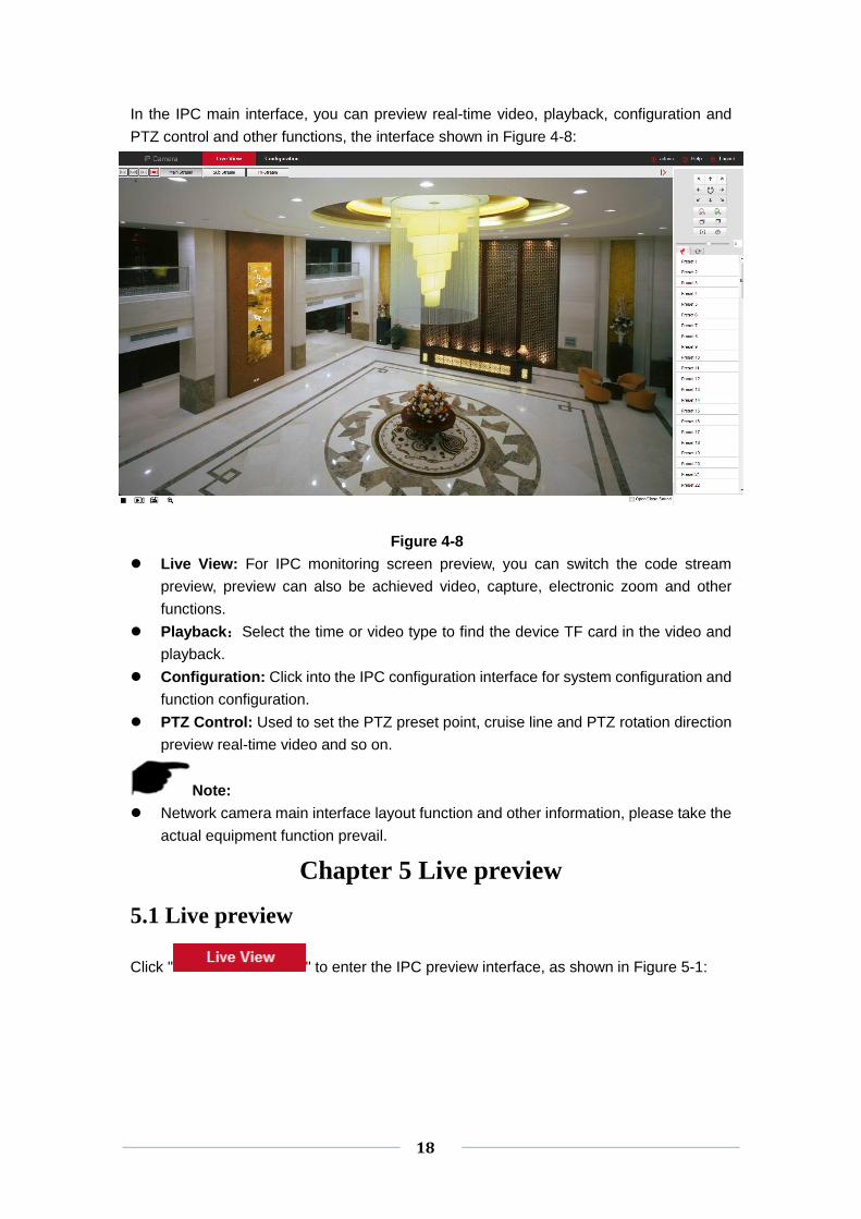
⑥ Other
In the main interface, click "Configure →Network → Advanced Setup → Other" to enter
the Video Password Authentication interface, as shown in Figure 7-19 below:
Figure 7-19
Here, the video password authentication is enabled. All devices connected to the camera,
the platform in the connection IPC, you must enter the IPC user name and password in
order to properly connect.
⑦ Wifi
In the main interface, click "Configure →Network → Advanced Setup → Wifi" to enter
the WIFI configuration interface. Here you can configure the camera to connect the WiFi
to the camera, as shown in Figure 7-20 below:

40
Figure 7-20
IPC WIFI configuration steps are as follows:
Step 1: Click the "Scan" button to search for nearby WiFi hotspots;
Step 2: Select to connect WiFi, enter the WiFi password;
Step 3: Turn on "Enable DHCP" and click "Save".
Note:
Normal camera without Wifi configuration interface, please take the specific function
of the specific camera.
Also can not open the DHCP, manual input and choose the same WiFi network
segment of the preferred DNS server IP address, default gateway, set the camera
WiFi network information.
⑧ PTZ
In the main interface, click "Configure →Network → Advanced Setup → PTZ" to enter
the PTZ configuration interface. as shown in Figure 7-21 below:

41
Figure7-21
7.4 Video
In the main interface, click "Configure → Video" to enter the video and audio
configuration interface, where you can set the device video, audio and other functions.
7.4.1 Video
In the main interface click "configuration → video → video" into the video configuration
interface, where you can set the IPC device name, stream type, encoding and other video
parameters, as shown in Figure 7-22:
Figure 7-22
【Device Name】Setting your camera name.
【Stream Type】Here Single/Third available.
【Codec】Choose coding and resolution.
【Framerate】Set the frame rate of the current output video of the device.
【Bit Rate】Support 64-12000kbps. The higher the bit rates the better video quality, but it
occupy the greater network bandwidth and the greater the pressure transmission.
【Variable (fixed) code rate】 Switch the code rate output mode in the drop-down menu,
42
fixed rate and variable rate.
【I Frame Interval】IPC acquisition keyframe interval, can be set 1-5s.
【Profile】Default is the Main Profile, you can select Baseline Profile or High Profile.
Note:
Different IPC, device stream type, encoding, frame rate and other information in the
drop-down menu options are also different.
When the frame rate is set too low, it will cause video cardton, please be careful.
The higher the bit rate, the greater the current network bandwidth and the greater the
transmission pressure.
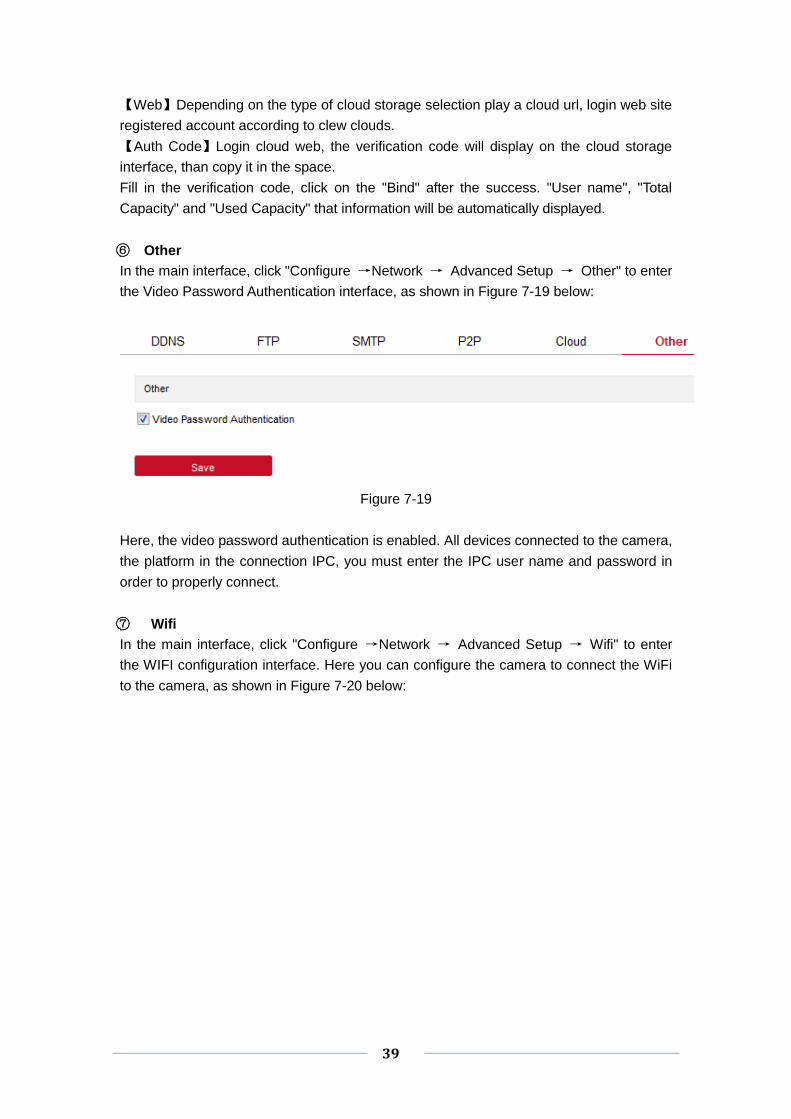
7.4.2 Audio
In the main interface, click "Configure → Video → Audio" to enter the audio
configuration interface, where you can set the device audio input mode, select the audio
code, set the input volume, as shown in Figure 7-23:
Figure 7-23
【Audio Enable】Turn on / off device audio input.
【Audio Input】Select the audio input method.
【Audio Encode】Choose audio encoding, G711U or G711A.
【Input Volume】Set the device input volume.
【Output Volume】Set the device output volume.
7.5 Image
In the main interface, click "Configuration → Image" to enter the image configuration
interface, where you can set the device image and OSD text and other information.
7.5.1 Image
In the main interface, click "Configuration → Image → Image" to enter the image
configuration interface, where you can adjust the related image parameters such as
device image, IRcut, Exposure Settings,Backlight Settings, White balance, Image
Enhancement ,Defog Model ,as shown in Figure 7-24:

43
Figure 7-24
【Brightness/Contrast/Saturation/Sharpness】You can input the value manually to set
brightness, contrast, saturation, sharpness. These parameters shall be set according to
the actual environment. The scope of valid values is from 0 to 255, you can drag the slider
to set, and the default value is 128. as shown in Figure 7-25:
Figure 7-25
【IRcut】Used to switch IRcut conversion time and set IRcut switch mode. Switch the
IRcut conversion time, and the 2-10S option in the drop-down menu. IRcut mode defaults
to LDR Auto, drop-down menu with Video Auto, Color, B/W options. As shown in Figure
7-26:
Figure 7-26
【Exposure Settings】The default is automatic exposure, according to the actual need to
switch the manual exposure mode, select "manual", the electronic shutter and gain
adjustment is activated, click [Save]. As shown in Figure 7-27:

44
Figure 7-27
【BackLight Settings】The default is off, can be manually turned on, the amount of
backlight can be set to minimum, medium, maximum. As shown in Figure 7-28 below:
Figure7-28
【White Balance】Default auto, switchable Manual, Fluorescent Lamp, Incandescent,
Warm Light, Natural Light. As shown in Figure 7-29:
Figure 7-29
- Manual white balance, support R, G, B gain adjustable, adjust the range (0-255), set
the click 【Save】.
- Fluorescent lamp for 6500K or so color temperature environment.
- Incandescent lamp for 3000K color temperature environment.
- The warm light is suitable for the color temperature environment around 4000K.
- Natural light for 5500K or so color temperature environment.
Note:
The actual configuration interface, please specify the specific model.
【Video Adjustment】Here you can set 2D or 3D digital noise reduction, as shown in
Figure 7-30:

45
Figure 7-30
Note:
The actual configuration interface, please specify the specific model.
【Image Enhancement】Including flicker control, wide dynamic switch, HDR, as shown in
Figure 7-31:
Figure 7-31
Flicker Control: The flash mode is selected according to the camera installation
environment and the flicker standard; normally 50 Hz for PAL standard and 60 Hz for
NTSC Standard, when the equipment is installed outdoors, you can choose outdoor.
WDR:Default Shut Down, you can switch in the drop-down menu automatically, Weak,
Moderate, Strong, Super.
【Defog Model】Used to set the de-fog mode and strength, as shown in Figure 7-32
below:
Figure 7-32
Defog Model: The default is off, you can choose from the drop-down menu to open or
automatically.
Defog Strength: The default is 0, when the fog mode is open, you can set the fog
strength, can be set to a value range of 0-255.
7.5.2 OSD
In the main interface, click "Configuration → Image → OSD" to enter the OSD
configuration interface, where you can set the preview interface to display menu time,
OSD text and other information, as shown in Figure 7-33:

46
Figure 7-33
【Time】Turn on / off the preview interface time display.
【Text】Turn on / off the preview interface OSD text display.
【Date Format】Set the preview interface to display the date format, default day / month /
year, switchable month / day / year and year / month / day options.
【OSD Position】Set the preview interface to display the time or OSD text position, the
default is the Top_Left, you can switch the Bottom_Left.
【Text】Enter the preview interface to display text information, such as hall elevator, hall
door and other equipment location information.
【Mirror】The default is OFF, you can switch VERTICAL, HORIZONTAL, BOTH, when the
device video image is reversed, through the menu to flip the image.
【Corridor Pattern】The default is off, open the corridor mode, you can choose to preview
the interface rotated 90 degrees and 270 degrees.
7.6 Events
In the main interface, click "Configuration → Events" to enter the event configuration
interface, where you can set the device's motion detection alarm, privacy mask, block
alarm, exception and other events.
○1 Motion Detection
In the main interface click on the "Configuration → Events → Motion Detection" to enter
the motion detection settings interface, where you can set the motion detection alarm area,
arming time, linkage mode and other related parameters, as shown in Figure 7-34:

47
Figure 7-34
【Enable】Turn on / off device motion detection alarm.
Area Settings: Select the area to set the motion detection sensitivity.
【Select All】Motion detection range to monitor all of the area, which Consists of
396(22*18) small squares.
【Manually draw the alarm area】Move the mouse to the preview screen, click the left
mouse button to select the range of motion detection, release the left mouse button to
complete the alarm area selection. A camera can select multiple motion detection zones
at the same time.
【Clear All】Clearing all the motion detecting area that selected currently.
【Sensitivity】The default is 5, can switch the range of 0-10, the greater the value of the
more sensitive equipment alarm.
Arming Schedule:As shown in Figure 7-35, you can view, edit, delete the motion
detection of the deployment time, the default for all-day deployment, can be adjusted by
the following way to adjust the deployment of mobile detection time:
- Method 1: Click the arming time period, manually fill in the start time and end time, set
up and click Save. If you need to delete the time period, click the "Delete" button and
then reset the time period.
- Method 2: Click the time of deployment, the time period will display two circles at both
ends, the mouse moves to the circle, will show the left and right direction of the
adjustment arrow, and move the adjustment arrow to adjust the arming time.
- You can set up more than one time period for up to 8 time periods.

48
- After the day of deployment time is set, if the other time also need to set the same
arming time, click the right side of the timeline " " copy button, in the "copy to"
interface check the "Select All" or a day, then Click "OK".
- After setting, click "Save" to complete the deployment time of the motion detection
configuratio.
Figure 7-35
Note:
When the arming time is set, there can be no overlap between any two time periods.
Linkage Method: When the motion detection to open the alarm linkage, there are a
variety of alarm linkage, linkage, including conventional linkage, linkage alarm output, as
shown in Figure 7-36:
【General Linkage】Including uploading SMTP,uploading FTP, uploading cloud and SD
card record.
【Upload Via SMTP】Select and the system is configured with SMTP, the alarm
information will be sent to the SMTP recipient mailbox.
【Upload Via FTP】Select and the system is configured with the FTP server, will send the
alarm information to the FTP server.
【Upload Via Cloud】Select and the system is configured with the cloud server, will send
the alarm information to the cloud account.
【Record Via SDcard】Select and configure the system video, the alarm will record the
alarm video to the IPC SD card.

49
.
Figure 7-36
Open the "General linkage", "upload Via SMTP", "upload Via FTP", "upload Via
Cloud", ”Record Via SDcard” function, when the device motion detection alarm, the
linkage corresponding way to inform the user.
○2 Privacy Mask
In the main interface, click "Configuration → Event → Privacy" to enter the privacy mask
settings interface. As shown in Figure 7-37:
Figure 7-37
Here you can choose up to 3 occlusion areas. Hold down the left mouse button and drag
to select the area in the area. Region 1、Region 2、Region 3 bellow will show the
corresponding coordinates, width, and height of the region .If you want to delete a region,
click on the corresponding “Delete” button. Click on the “Save” after completing the
setting.
○3 Video Tampering

50
In the main interface click on the "configuration → Events → Video Tampering" to enter
the video tampering settings interface. As shown in Figure 7-38:
Figure 7-38
【Enable】Turn on / off device video tampering alarm.
Area Settings: Select the area to set the video tampering sensitivity.
【Drawing Area / Stop Drawing】Move the mouse to the preview screen, click the left
mouse button to select the range of motion detection, release the left mouse button, click
“Stop Drawing” to complete the alarm area selection.
【Clear All】Clearing all the video tempering area that selected currently.
【Sensitivity】The default is 0, can switch the range of 0-2, the greater the value of the
more sensitive equipment alarm.
Arming Schedule:As shown in Figure 7-39, you can view, edit, delete the video
tempering of the deployment time, default all day 0 arming, can be adjusted by the
following way to adjust the deployment of video tempering time:
- Method 1: In the arming time period, hold down the left mouse button to drag the
mouse to the right to select the time period.
- Method 2: Click the arming time period, manually fill in the start time and end time, set
up and click Save after setting. If you need to delete the time period, click the "Delete"
button and then reset the time period.
- Method 3: Click the time of deployment, the time period will display two circles at both
ends, the mouse moves to the circle, will show the left and right direction of the
adjustment arrow, and move the adjustment arrow to adjust the arming time.

51
- You can set up more than one time period for up to 8 time periods.
- After the day of deployment time is set, if the other time also need to set the same
arming time, click the right side of the timeline " " copy button, in the "copy to"
interface check the "Select All" or a day, then Click "OK".
- After setting, click "Save" to complete the deployment time of the motion detection
configurat.
Figure 7-39
Note:
When the arming time is set, there can be no overlap between any two time periods.
Linkage Method: Alarm linkage mode upload SMTP and upload FTP regular linkage, as
shown in Figure 7-40:
【General Linkage】Including uploading SMTP and uploading FTP.
【Upload Via SMTP】Select and the system is configured with SMTP, the alarm
information will be sent to the SMTP recipient mailbox.
【Upload Via FTP】Select and the system is configured with the FTP server, will send the
alarm information to the FTP server.

52
Figure 7-40
Here to open the "regular linkage", "upload FTP", "upload SMTP" function, when the
device settings area is blocked and alarm, the corresponding way to inform the user.
○4 Alarm Input
In the main interface click on the "configuration → Events → Alarm Input" to enter the
Alarming Schedule settings interface.
Arming Schedule:As shown in Figure 7-41, you can view, edit, delete the video
tempering of the deployment time, default all day 0 arming, can be adjusted by the
following way to adjust the deployment of alarm input time:
- Method 1: In the arming time period, hold down the left mouse button to drag the
mouse to the right to select the time period.
- Method 2: Click the arming time period, manually fill in the start time and end time, set
up and click Save after setting. If you need to delete the time period, click the "Delete"
button and then reset the time period.
- Method 3: Click the time of deployment, the time period will display two circles at both
ends, the mouse moves to the circle, will show the left and right direction of the
adjustment arrow, and move the adjustment arrow to adjust the arming time.
- You can set up more than one time period for up to 8 time periods.
- After the day of deployment time is set, if the other time also need to set the same
arming time, click the right side of the timeline " " copy button, in the "copy to"
interface check the "Select All" or a day, then Click "OK".
- After setting, click "Save" to complete the deployment time of the motion detection
configurat.

53
Figure 7-41
Linkage mode settings: Alarm linkage, including upload SMTP and FTP upload the
normal linkage and IO output of the linkage alarm output, as shown in Figure 7-42:
【Regular linkage】 Including upload SMTP and upload FTP.
【Upload Via SMTP】Select and the system is configured with SMTP, the alarm
information will be sent to the SMTP recipient mailbox.
【Upload Via FTP】Select and the system is configured with the FTP server, will send the
alarm information to the FTP server.
【Linkage Alarm Output】 Including IO output.
【IO Output】 Be enabled and the device IO port is connected to the output alarm device.
When there is alarm input, the alarm device connected with IO port will make the
corresponding alarm action.
.
Figure 7-42
○4 Exception
In the main interface, click "Configuration → Event → Except" to enter the exception
settings interface. As shown in Figure 7-43:
Figure 7-43

54
Set the "Cable Disconnection" and "IP Address Conflict" alarms here, and set the alarm
output mode. Click on the “Save” after completing the settings.
Chapter 8 App client
8.1 Installation & Register
FreeIP process: register→login→add device→service application
Step 1 For your mobile phone, please scan the corresponding QR code as shown in Figure 8-1, download and install "FreeIP " in your mobile phone. You can also log in “FreeIP “official website http://www.freeip.com or Google play to download and install as steps suggested. Android application downloads address:
https://play.google.com/store/apps/details?id=com.xc.hdscreen
iOS application downloads address:
https://itunes.apple.com/cn/app/freeip/id898690336?mt=8
Figure 8-1 Android iOS
Note:
The mobile client currently only supports iOS and Android systems.
iOS users directly in the App Store search "FreeIP", to download and install.
Step 2 After installation, run "FreeIP", register an account according to the interface prompts.
8.2 Add device
Step 1: Make sure that IPC is connected to the internet, P2P is on, and is online.
Step 2: Set up the phone network; connect the phone to the wireless network.
Step 3: Log into the mobile client and select “Device” from the sliding sidebar. The sliding
sidebar is shown in Figure 8-2.

55
Figure 8-2
Click “+” in the upper right corner, then scan the QR code on the device or in the P2P
interface, as show in Figure 8-3.
Figure 8-3
Step 4 The phone will automatically recognize the QR code, enter the IPC user name ,
password and verification code, verification code printed on the random shipping standard
label,click “ Submit”, then set the camera note and the camera groups, after
clicking ”Send”, prompt “Add successful” will show up.
8.3 Live Preview
Step 1 Select “Preview” from the App toolbar, then comes to the preview interface, as
Figure 8-4.

56
Figure 8-4
Step 2 Click “+” in the preview window as shown in Figure 8-5.
Figure 8-5
Step 3 Select the device preview channel in the device list group, then click “Preview” as
shown in Figure 8-6.
Figure 8-6

57
Step 4 In the preview interface, you can choose multi-screen preview mode, as shown in
Figure 8-7.
Figure 8-7
Phone full-screen preview as shown in Figure 8-8.
Figure 8-8
Note:
In the real-time preview interface in addition to switch preview mode, you can also do
video, capture, set the sound and other operations, if the channel has PTZ function,
but also do control PTZ, focus and other actions.
8.4 Playback
FreeIP app playback is used to play back images recorded in the IPC SD card and
recorded on the NVR hard disk.
Step 1 Select “Playback” from the App toolbar, then comes to the video playback interface,
as Figure 8-9.

58
Figure 8-9
Step 2 Click "+" in the preview window, as shown in Figure 8-10.
Figure 8-10
Step 3 Select the device playback channel in the device list group, then click "Playback "
as shown in Figure 8-11.
Figure 8-11

59
Step 4 The recording of the playback device is shown in Figure 8-12.
Figure 8-12
Note:
In the playback interface in addition to switch preview mode, you can also do video,
capture, set the sound and other operations.

60
Chapter 9 Frequently Asked Questions
1.Why can not access the camera by IE?
Answer: There maybe 4 reasons, Details are as follows:
a.The network unreasonable?
Solution: First you can connect network by PC, check the network cable if it is good.
And check the network between the camera and the PC is good.
b.The IP address of the camera is occupied by other device or PC?
Solution: You can connect the camera with your PC directly, and modify the IP address
or use the IP search tool.
c.The camera maybe in other network segment?
Solution: Check the IP address and net mask.
2. Why can not access the camera after update?
Answer: Clean browser cache.
Step: open IE, click “Tools” and select “Internet Options”, then you can see “Temporary
Internet files” and click “Delete Files”, it will prompt a dialog you need to check “Delete all
offline content” and click “OK”.
Also you can click “Start” and select “Run” then enter “cmd”, enter “arp -d” in “Command
Prompt” interface. Re-access the camera.
3. Why cannot show the whole interface?
Answer: Close some options of IE.
Step: Open IE, click “View” and select “Toolbar”, close the “Favorites bar”, “Status bar”
and “Command bar”.