NetVanta 7000 Series Hardware Installation Guide
56
NetVanta 7000 Series Hardware Installation Guide 1200796E1/L1 NetVanta 7100 PoE 1200690E1/L1 NetVanta Quad FXS Voice Interface Module 1200691E1/L1 NetVanta Quad FXO Voice Interface Module 1200692E1/L1 NetVanta Dual FXS/FXO Voice Interface Module 1200695L1 NetVanta T1/PRI Voice Interface Module 1200861L1 NetVanta 56K/64K Network Interface Module 1200862L2#NEBS NetVanta T1/FT1 NEBS Network Interface Module 1202862L1 NetVanta T1/FT1 Network Interface Module 1202863L1 NetVanta T1/FT1 + DSX-1 Network Interface Module 1200872L1 NetVanta Dual T1 Network Interface Module 1200868E1/L1 NetVanta E1/FE1 Network Interface Module 1200878E1/L1 NetVanta E1/FE1 + G.703 Drop Network Interface Module 1200866E1/L1 NetVanta Serial Network Interface Module 1200867L1 NetVanta SHDSL Network Interface Module 1200869E1/L1 NetVanta ADSL Network Interface Module, Annex A 1200889E1/L1 NetVanta ADSL Network Interface Module, Annex B 1200864L1 NetVanta Analog Modem Dial Backup Interface Module 1200865L1 NetVanta ISDN BRI Dial Backup Interface Module 1200875L1 NetVanta ISDN S/T Dial Backup Interface Module 1200480L1 1000BaseSX Multi-Mode SFP Module 1200481L1 1000BaseLX Single-Mode SFP Module 1202368L1 NetVanta VPN Accelerator Card 61200796L1-34D July 2006
-
Upload
matthew-ortiz -
Category
Documents
-
view
67 -
download
5
Transcript of NetVanta 7000 Series Hardware Installation Guide

NetVanta 7000 Series Hardware Installation Guide
1200796E1/L1 NetVanta 7100 PoE
1200690E1/L1 NetVanta Quad FXS Voice Interface Module
1200691E1/L1 NetVanta Quad FXO Voice Interface Module
1200692E1/L1 NetVanta Dual FXS/FXO Voice Interface Module
1200695L1 NetVanta T1/PRI Voice Interface Module
1200861L1 NetVanta 56K/64K Network Interface Module
1200862L2#NEBS NetVanta T1/FT1 NEBS Network Interface Module
1202862L1 NetVanta T1/FT1 Network Interface Module
1202863L1 NetVanta T1/FT1 + DSX-1 Network Interface Module
1200872L1 NetVanta Dual T1 Network Interface Module
1200868E1/L1 NetVanta E1/FE1 Network Interface Module
1200878E1/L1 NetVanta E1/FE1 + G.703 Drop Network Interface Module
1200866E1/L1 NetVanta Serial Network Interface Module
1200867L1 NetVanta SHDSL Network Interface Module
1200869E1/L1 NetVanta ADSL Network Interface Module, Annex A
1200889E1/L1 NetVanta ADSL Network Interface Module, Annex B
1200864L1 NetVanta Analog Modem Dial Backup Interface Module
1200865L1 NetVanta ISDN BRI Dial Backup Interface Module
1200875L1 NetVanta ISDN S/T Dial Backup Interface Module
1200480L1 1000BaseSX Multi-Mode SFP Module
1200481L1 1000BaseLX Single-Mode SFP Module
1202368L1 NetVanta VPN Accelerator Card
61200796L1-34DJuly 2006

Trademarks NetVanta 7000 Series Hardware Installation Guide
TrademarksAny brand names and product names included in this manual are trademarks, registered trademarks, or trade names of their respective holders.
To the Holder of the ManualThe contents of this manual are current as of the date of publication. ADTRAN reserves the right to change the contents without prior notice.
In no event will ADTRAN be liable for any special, incidental, or consequential damages or for commercial losses even if ADTRAN has been advised thereof as a result of issue of this publication.
Software Licensing AgreementEach ADTRAN product contains a single license for ADTRAN supplied software. Pursuant to the Licensing Agreement, you may: (a) use the software on the purchased ADTRAN device only and (b) keep a copy of the software for backup purposes. This Agreement covers all software installed on the system as well as any software available on the ADTRAN website. In addition, certain ADTRAN systems may contain additional conditions for obtaining software upgrades.
901 Explorer BoulevardP.O. Box 140000
Huntsville, AL 35814-4000Phone: (256) 963-8000
Copyright © 2006 ADTRAN, Inc.All Rights Reserved.
Printed in U.S.A.
Changes or modifications to this unit not expressly approved by the party responsible for compliance could void the user’s authority to operate the equipment.
2 Copyright © 2006 ADTRAN, Inc. 61200796L1-34D

NetVanta 7000 Series Hardware Installation Guide Conventions
Conventions
Notes provide additional useful information.
Cautions signify information that could prevent service interruption or damage to the equipment.
Warnings provide information that could prevent injury or endangerment to human life.
61200796L1-34D Copyright © 2006 ADTRAN, Inc. 3
Safety Instructions NetVanta 7000 Series Hardware Installation Guide
Safety InstructionsWhen using your telephone equipment, please follow these basic safety precautions to reduce the risk of fire, electrical shock, or personal injury:
1. Do not use this product near water, such as a bathtub, wash bowl, kitchen sink, laundry tub, in a wet basement, or near a swimming pool.
2. Avoid using a telephone (other than a cordless-type) during an electrical storm. There is a remote risk of shock from lightning.
3. Do not use the telephone to report a gas leak in the vicinity of the leak.
4. Use only the power cord, power supply, and/or batteries indicated in the manual. Do not dispose of batteries in a fire. They may explode. Check with local codes for special disposal instructions.
5. The socket-outlet shall be installed near the equipment and shall be easily accessible.
Save These Important Safety Instructions
This equipment incorporates double pole/neutral fusing. If the neutral fuse opens and the line fuse does not open, voltage could still be present in the unit.
4 Copyright © 2006 ADTRAN, Inc. 61200796L1-34D
NetVanta 7000 Series Hardware Installation Guide FCC-Required Information
FCC-Required InformationFCC regulations require that the following information be provided in this manual:
1. This equipment complies with Part 68 of FCC rules and requirements adopted by ACTA. Each registered interface has a label that contains, among other information, a product identifier in the format US:AAAEQ##TXXXX. If requested, provide this information to the telephone company.
2. If this equipment causes harm to the telephone network, the telephone company may temporarily discontinue service. If possible, advance notification is given; otherwise, notification is given as soon as possible. The telephone company will advise the customer of the right to file a complaint with the FCC.
3. The telephone company may make changes in its facilities, equipment, operations, or procedures that could effect the proper operation of this equipment. Advance notification and the opportunity to maintain uninterrupted service are given.
4. If experiencing difficulty with this equipment, please contact ADTRAN for repair and warranty information. The telephone company may require this equipment to be disconnected from the network until the problem is corrected or it is certain the equipment is not malfunctioning.
5. This unit contains no user-serviceable parts.
6. This equipment is designed to connect to the telephone network or premises wiring using an FCC-compatible modular jack, which is compliant with Part 68 and requirements adopted by ACTA.
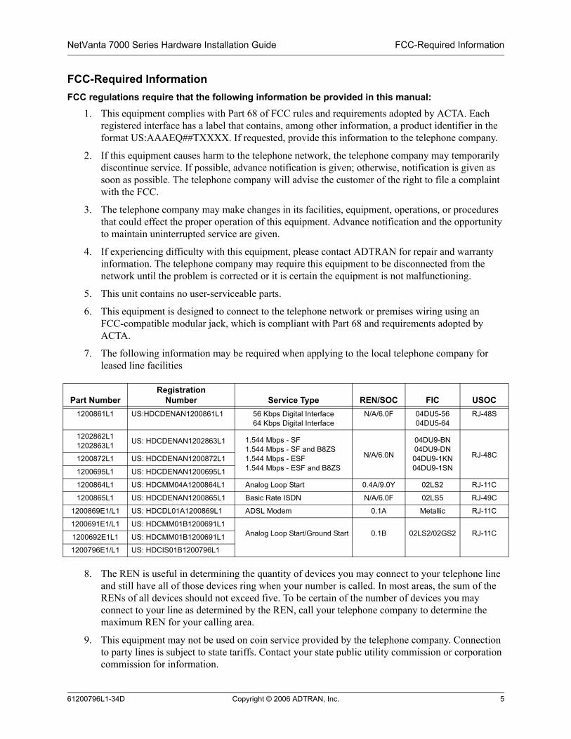
7. The following information may be required when applying to the local telephone company for leased line facilities
8. The REN is useful in determining the quantity of devices you may connect to your telephone line and still have all of those devices ring when your number is called. In most areas, the sum of the RENs of all devices should not exceed five. To be certain of the number of devices you may connect to your line as determined by the REN, call your telephone company to determine the maximum REN for your calling area.
9. This equipment may not be used on coin service provided by the telephone company. Connection to party lines is subject to state tariffs. Contact your state public utility commission or corporation commission for information.
Part NumberRegistration
Number Service Type REN/SOC FIC USOC1200861L1 US:HDCDENAN1200861L1 56 Kbps Digital Interface
64 Kbps Digital InterfaceN/A/6.0F 04DU5-56
04DU5-64RJ-48S
1202862L11202863L1 US: HDCDENAN1202863L1 1.544 Mbps - SF
1.544 Mbps - SF and B8ZS1.544 Mbps - ESF1.544 Mbps - ESF and B8ZS
N/A/6.0N
04DU9-BN04DU9-DN04DU9-1KN04DU9-1SN
RJ-48C1200872L1 US: HDCDENAN1200872L1
1200695L1 US: HDCDENAN1200695L1
1200864L1 US: HDCMM04A1200864L1 Analog Loop Start 0.4A/9.0Y 02LS2 RJ-11C
1200865L1 US: HDCDENAN1200865L1 Basic Rate ISDN N/A/6.0F 02LS5 RJ-49C
1200869E1/L1 US: HDCDL01A1200869L1 ADSL Modem 0.1A Metallic RJ-11C
1200691E1/L1 US: HDCMM01B1200691L1Analog Loop Start/Ground Start 0.1B 02LS2/02GS2 RJ-11C1200692E1L1 US: HDCMM01B1200691L1
1200796E1/L1 US: HDCIS01B1200796L1
61200796L1-34D Copyright © 2006 ADTRAN, Inc. 5

FCC Radio Frequency Interference Statement NetVanta 7000 Series Hardware Installation Guide
FCC Radio Frequency Interference StatementThis equipment has been tested and found to comply with the limits for a Class A digital device, pursuant to Part 15 of the FCC Rules. These limits are designed to provide reasonable protection against harmful interference when the equipment is operated in a commercial environment. This equipment generates, uses, and can radiate radio frequency energy and, if not installed and used in accordance with the instruction manual, may cause harmful interference to radio frequencies. Operation of this equipment in a residential area is likely to cause harmful interference in which case the user will be required to correct the interference at his own expense.
Electromagnetic Compatibility (EMC) Table for the NetVanta 7100NetVanta Module P/N and Name NetVanta 71001200861L1 56K/64K NIM FCC Part 15, Class A
EN 55022 Class A1200862L2#NEBS T1/FT1 NEBS NIM N/A1202862L11202863L11200872L1
T1/FT1 NIMT1/FT1 + DSX-1 NIMDual T1 NIM
FCC Part 15, Class A EN 55022 Class A
1200868E1/L1 1200878E1/L1
E1/FE1 NIME1/FE1 + G.703 Drop
FCC Part 15, Class A EN 55022 Class AEN 55024EN 61000-3-2EN 61000-3-3
1200866E1/L1 Serial NIM FCC Part 15, Class A EN 55022 Class AEN 55024EN 61000-3-2EN 61000-3-3
1200867L1 SHDSL NIM FCC Part 15, Class A EN 55022 Class AEN 55024EN 61000-3-2EN 61000-3-3
1200869E1/L11200889E1/L1
ADSL NIM, Annex AADSL NIM, Annex B
FCC Part 15, Class A EN 55022 Class AEN 55024EN 61000-3-2EN 61000-3-3
1200864L11200865L1 1200875L1
Analog Modem DIMISDN BRI DIMISDN S/T DIM
FCC Part 15, Class A EN 55022 Class AEN 55024EN 61000-3-2EN 61000-3-3
1202368L1 VPN Accelerator Card FCC Part 15, Class A EN 55022 Class AEN 55024EN 61000-3-2EN 61000-3-3
1200690E1/L1 FXS VIM UL 60950, Third Edition/CSA C22.2, No. 60950FCC Part 15 Class A
1200691E1/L1 FXO VIM UL 60950, Third Edition/CSA C22.2, No. 60950FCC Part 15 Class A and Part 68
1200692E1/L1 FXS/FXO VIM UL 60950, Third Edition/CSA C22.2, No. 60950FCC Part 15 Class A and Part 68
1200695L1 T1/PRI VIM FCC Part 15 Class A,EN 55022 Class AACTA/FCC Part 68, IC CS-03 UL/CUL 60950
1200796E1/L1 NetVanta 7100 FCC Part 15 Class AFCC Part 68Industry CanadaCE MarkEN55022: 1998 (radiated and conducted emissions)EN 55024: 1998 (immunity)EN 61000-3-2: 1995 Voltage Fluctuations and FlickerUL 60950TS001
6 Copyright © 2006 ADTRAN, Inc. 61200796L1-34D

NetVanta 7000 Series Hardware Installation Guide Industry Canada Compliance Information
Industry Canada Compliance InformationNotice: The Industry Canada label applied to the product (identified by the Industry Canada logo or the “IC:” in front of the certification/registration number) signifies that the Industry Canada technical specifications were met.
Notice: The Ringer Equivalence Number (REN) for this terminal equipment is supplied in the documentation or on the product labeling/markings. The REN assigned to each terminal device indicates the maximum number of terminals that can be connected to a telephone interface. The termination on an interface may consist of any combination of devices subject only to the requirement that the sum of the RENs of all the devices should not exceed five (5).
Canadian Emissions RequirementsThis digital apparatus does not exceed the Class A limits for radio noise emissions from digital apparatus as set out in the interference-causing equipment standard entitled “Digital Apparatus,” ICES-003 of the Department of Communications.
Cet appareil numérique respecte les limites de bruits radioelectriques applicables aux appareils numériques de Class A prescrites dans la norme sur le materiel brouilleur: “Appareils Numériques,” NMB-003 edictee par le ministre des Communications.
61200796L1-34D Copyright © 2006 ADTRAN, Inc. 7

Warranty NetVanta 7000 Series Hardware Installation Guide
WarrantyADTRAN will repair and return this product within the warranty period if it does not meet its published specifications or fails while in service. Warranty information can be found in the Support section of the ADTRAN website at http://www.adtran.com.
Product RegistrationRegistering your product helps ensure complete customer satisfaction. Please take time to register your products in the Support section of the ADTRAN website at http://www.adtran.com
Product Support InformationA return material authorization (RMA) is required prior to returning equipment to ADTRAN. For service, RMA requests, training, or more information, use the contact information shown below.
Repair and Return
If you determine that a repair is needed, please contact our Customer and Product Service (CaPS) department to have an RMA number issued. CaPS should also be contacted to obtain information regarding equipment currently in house or possible fees associated with repair.
Identify the RMA number clearly on the package (below the address), and return to the following address:
Pre-Sale Inquiries and Applications Support
Your reseller should serve as the first point of contact for support. If additional pre-sales support is needed, the ADTRAN Support website provides a variety of support services such as a searchable knowledge base, the latest product documentation, application briefs, case studies, and a link to submit a question to an Applications Engineer. All of this, and more, is available in the Support section of the ADTRAN website at http://www.adtran.com.
When needed, further pre-sales assistance is available by calling our Applications Engineering Department.
CaPS Department (256) 963-8722
ADTRAN Customer and Product Service901 Explorer Blvd. (East Tower)Huntsville, Alabama 35806
RMA # _____________
Applications Engineering (800) 615-1176
8 Copyright © 2006 ADTRAN, Inc. 61200796L1-34D

NetVanta 7000 Series Hardware Installation Guide Product Support Information
Post-Sale Support
Your reseller should serve as the first point of contact for support. If additional support is needed, the ADTRAN website provides a variety of support services such as a searchable knowledge base, updated firmware releases, latest product documentation, service request ticket generation and trouble-shooting tools. All of this, and more, is available in the Support section of the ADTRAN website at http://www.adtran.com.
When needed, further post-sales assistance is available by calling our Technical Support Center. Please have your unit serial number available when you call.
Installation and Maintenance Support
The ADTRAN Custom Extended Services (ACES) program offers multiple types and levels of installation and maintenance services which allow you to choose the kind of assistance you need. This support is available at:
For questions, call the ACES Help Desk.
Training
The Enterprise Network (EN) Technical Training Department offers training on our most popular products. These courses include overviews on product features and functions while covering applications of ADTRAN's product lines. ADTRAN provides a variety of training options, including customized training and courses taught at our facilities or at your site. For more information about training, please contact your Territory Manager or the Enterprise Training Coordinator.
Technical Support (888) 4ADTRANInternational Technical Support 1-256-963-8716
http://www.adtran.com/aces
ACES Help Desk (888) 874-ACES (2237)
Training Phone (800) 615-1176, ext. 7500 Training Fax (256) 963-6700Training Email [email protected]
61200796L1-34D Copyright © 2006 ADTRAN, Inc. 9

NetVanta 7000 Series Hardware Installation Guide
10 Copyright © 2006 ADTRAN, Inc. 61200796L1-34D

Table of Contents
Introduction . . . . . . . . . . . . . . . . . . . . . . . . . . . . . . . . . . . . . . . . . . . . . . . . . . . . . . . . . . . . . . . . . . . . . . . 17Power Over Ethernet . . . . . . . . . . . . . . . . . . . . . . . . . . . . . . . . . . . . . . . . . . . . . . . . . . . . . . . . . . . . . 18Unpacking and Inspecting the System . . . . . . . . . . . . . . . . . . . . . . . . . . . . . . . . . . . . . . . . . . . . . . . . 18
Product Features and Specifications . . . . . . . . . . . . . . . . . . . . . . . . . . . . . . . . . . . . . . . . . . . . . . . . . . 19
Physical Description . . . . . . . . . . . . . . . . . . . . . . . . . . . . . . . . . . . . . . . . . . . . . . . . . . . . . . . . . . . . . . . 21Front Panel RJ-45 Ports and LEDS . . . . . . . . . . . . . . . . . . . . . . . . . . . . . . . . . . . . . . . . . . . . . . . . . . 21Front Panel Gigabit Ethernet Interfaces and LEDs . . . . . . . . . . . . . . . . . . . . . . . . . . . . . . . . . . . . . . 21Other Front Panel LEDs . . . . . . . . . . . . . . . . . . . . . . . . . . . . . . . . . . . . . . . . . . . . . . . . . . . . . . . . . . . 21Rear Panel Description . . . . . . . . . . . . . . . . . . . . . . . . . . . . . . . . . . . . . . . . . . . . . . . . . . . . . . . . . . . 23
Option Modules . . . . . . . . . . . . . . . . . . . . . . . . . . . . . . . . . . . . . . . . . . . . . . . . . . . . . . . . . . . . . . . . . . . 24Network Interface Modules . . . . . . . . . . . . . . . . . . . . . . . . . . . . . . . . . . . . . . . . . . . . . . . . . . . . . . . . 25Dial Backup Interface Modules . . . . . . . . . . . . . . . . . . . . . . . . . . . . . . . . . . . . . . . . . . . . . . . . . . . . . 40
Unit Installation . . . . . . . . . . . . . . . . . . . . . . . . . . . . . . . . . . . . . . . . . . . . . . . . . . . . . . . . . . . . . . . . . . . . 43Tools Required . . . . . . . . . . . . . . . . . . . . . . . . . . . . . . . . . . . . . . . . . . . . . . . . . . . . . . . . . . . . . . . . . . 43Mounting Options . . . . . . . . . . . . . . . . . . . . . . . . . . . . . . . . . . . . . . . . . . . . . . . . . . . . . . . . . . . . . . . . 44Supplying Power to the Unit . . . . . . . . . . . . . . . . . . . . . . . . . . . . . . . . . . . . . . . . . . . . . . . . . . . . . . . . 46Installing Dial Backup and Network Interface Modules . . . . . . . . . . . . . . . . . . . . . . . . . . . . . . . . . . . 47
Appendix A. Connector Pin Definitions. . . . . . . . . . . . . . . . . . . . . . . . . . . . . . . . . . . . . . . . . . . . . . . 49
61200796L1-34D Copyright © 2006 ADTRAN, Inc. 11

Table of Contents NetVanta 7000 Series Hardware Installation Guide
12 Copyright © 2006 ADTRAN, Inc. 61200796L1-34D

List of Figures
Figure 1. NetVanta 7100 Front Panel Layout . . . . . . . . . . . . . . . . . . . . . . . . . . . . . . . . . . . . . . . . . . . . 21Figure 2. NetVanta 7100 Rear Panel . . . . . . . . . . . . . . . . . . . . . . . . . . . . . . . . . . . . . . . . . . . . . . . . . . 23Figure 3. NetVanta 56K/64K NIM . . . . . . . . . . . . . . . . . . . . . . . . . . . . . . . . . . . . . . . . . . . . . . . . . . . . . 25Figure 4. NetVanta T1/FT1 NIM . . . . . . . . . . . . . . . . . . . . . . . . . . . . . . . . . . . . . . . . . . . . . . . . . . . . . . 26Figure 5. NetVanta T1/FT1 NEBS NIM . . . . . . . . . . . . . . . . . . . . . . . . . . . . . . . . . . . . . . . . . . . . . . . . . 27Figure 6. NetVanta T1/FT1 + DSX-1 NIM . . . . . . . . . . . . . . . . . . . . . . . . . . . . . . . . . . . . . . . . . . . . . . . 28Figure 7. NetVanta Dual T1 NIM . . . . . . . . . . . . . . . . . . . . . . . . . . . . . . . . . . . . . . . . . . . . . . . . . . . . . . 29Figure 8. NetVanta E1/FE1 NIM . . . . . . . . . . . . . . . . . . . . . . . . . . . . . . . . . . . . . . . . . . . . . . . . . . . . . . 30Figure 9. NetVanta E1/FE1 + G.703 Drop NIM . . . . . . . . . . . . . . . . . . . . . . . . . . . . . . . . . . . . . . . . . . . 31Figure 10. NetVanta Serial NIM . . . . . . . . . . . . . . . . . . . . . . . . . . . . . . . . . . . . . . . . . . . . . . . . . . . . . . . . 32Figure 11. NetVanta SHDSL NIM . . . . . . . . . . . . . . . . . . . . . . . . . . . . . . . . . . . . . . . . . . . . . . . . . . . . . . 33Figure 12. NetVanta ADSL NIM, Annex A . . . . . . . . . . . . . . . . . . . . . . . . . . . . . . . . . . . . . . . . . . . . . . . . 34Figure 13. NetVanta ADSL NIM, Annex B . . . . . . . . . . . . . . . . . . . . . . . . . . . . . . . . . . . . . . . . . . . . . . . . 35Figure 14. NetVanta T1/PRI VIM . . . . . . . . . . . . . . . . . . . . . . . . . . . . . . . . . . . . . . . . . . . . . . . . . . . . . . . 36Figure 15. NetVanta Quad FXS VIM, . . . . . . . . . . . . . . . . . . . . . . . . . . . . . . . . . . . . . . . . . . . . . . . . . . . 37Figure 16. NetVanta Quad FXO VIM . . . . . . . . . . . . . . . . . . . . . . . . . . . . . . . . . . . . . . . . . . . . . . . . . . . . 38Figure 17. NetVanta Dual FXS/FXO VIM . . . . . . . . . . . . . . . . . . . . . . . . . . . . . . . . . . . . . . . . . . . . . . . . 39Figure 18. Wallmount Installation . . . . . . . . . . . . . . . . . . . . . . . . . . . . . . . . . . . . . . . . . . . . . . . . . . . . . . 45Figure 19. Installing DIMs . . . . . . . . . . . . . . . . . . . . . . . . . . . . . . . . . . . . . . . . . . . . . . . . . . . . . . . . . . . . 47Figure 20. NIM/VIM and DIM Installation . . . . . . . . . . . . . . . . . . . . . . . . . . . . . . . . . . . . . . . . . . . . . . . . . 48
61200796L1-34D Copyright © 2006 ADTRAN, Inc. 13

List of Figures NetVanta 7000 Series Hardware Installation Guide
14 Copyright © 2006 ADTRAN, Inc. 61200796L1-34D

List of Tables
Table 1. Front Panel LED Descriptions . . . . . . . . . . . . . . . . . . . . . . . . . . . . . . . . . . . . . . . . . . . . . . . . 22Table A-1. CONSOLE Port Pinouts . . . . . . . . . . . . . . . . . . . . . . . . . . . . . . . . . . . . . . . . . . . . . . . . . . . . . 49Table A-2. 10/100BaseT Ethernet Port Pinouts. . . . . . . . . . . . . . . . . . . . . . . . . . . . . . . . . . . . . . . . . . . . 49Table A-3. 1000BaseT Gigabit-Ethernet Port Pinouts . . . . . . . . . . . . . . . . . . . . . . . . . . . . . . . . . . . . . . . 50Table A-4. Analog - Onboard FXS and FXO Port Pinouts. . . . . . . . . . . . . . . . . . . . . . . . . . . . . . . . . . . . 50Table A-5. Alarm Contacts. . . . . . . . . . . . . . . . . . . . . . . . . . . . . . . . . . . . . . . . . . . . . . . . . . . . . . . . . . . . 50Table A-6. WAN-DDS Connector Pinouts . . . . . . . . . . . . . . . . . . . . . . . . . . . . . . . . . . . . . . . . . . . . . . . . 51Table A-7. WAN-T1 Connector Pinouts. . . . . . . . . . . . . . . . . . . . . . . . . . . . . . . . . . . . . . . . . . . . . . . . . . 51Table A-8. WAN-E1 Connector Pinouts. . . . . . . . . . . . . . . . . . . . . . . . . . . . . . . . . . . . . . . . . . . . . . . . . . 51Table A-9. DSX-1 Connector Pinouts . . . . . . . . . . . . . . . . . . . . . . . . . . . . . . . . . . . . . . . . . . . . . . . . . . . 52Table A-10. G.703 Connector Pinouts. . . . . . . . . . . . . . . . . . . . . . . . . . . . . . . . . . . . . . . . . . . . . . . . . . . . 52Table A-11. WAN-SHDSL Connector Pinouts . . . . . . . . . . . . . . . . . . . . . . . . . . . . . . . . . . . . . . . . . . . . . . 52Table A-12. WAN-ADSL Connector Pinouts . . . . . . . . . . . . . . . . . . . . . . . . . . . . . . . . . . . . . . . . . . . . . . . 52Table A-13. Serial to Cable Connector Pinouts . . . . . . . . . . . . . . . . . . . . . . . . . . . . . . . . . . . . . . . . . . . . . 53Table A-14. DBU Connector Pinouts . . . . . . . . . . . . . . . . . . . . . . . . . . . . . . . . . . . . . . . . . . . . . . . . . . . . . 54
61200796L1-34D Copyright © 2006 ADTRAN, Inc. 15

List of Tables NetVanta 7000 Series Hardware Installation Guide
16 Copyright © 2006 ADTRAN, Inc. 61200796L1-34D
1. INTRODUCTION
This hardware installation guide lists the NetVanta 7100 specifications, describes the physical characteristics of the unit, introduces basic functionality, and provides installation instructions.
The NetVanta 7100 is an Integrated Communications Platform (ICP) equipped with 24 Power over Ethernet (PoE) 10/100 Ethernet ports capable of supplying the full 15.4 watts described in the 802.3af specification along with 2 Gigabit Ethernet up link ports. The NetVanta 7100 is a 1U rack mountable chassis that supplies the user with VoIP capability for up to 50 user registrations. The unit is also equipped with several integrated ports including analog trunks (FXO), analog stations (FXS), Door Relays, Console, Compact Flash (Voicemail), WAN Ethernet port, Music on Hold, Paging, auto sensing AC Power, as well as two NIM/VIM slots.
The NetVanta 7100 is a cost-effective product built on the ADTRAN Operating System (AOS) platform and includes the AOS built-in IP router, VPN and firewall features. For details on the command line interface, refer to the Command Reference Guide (also included on the CD).
The common application of the NetVanta 7100 will be to allow customers to use SIP based IP phones and consolidate their existing voice and data networks. The NetVanta 7100 is also VPN-ready, allowing multi-site networking or secure remote user connectivity.
The NetVanta 7100 contains two Network Interface Module / Voice Interface Module (NIM/VIM) slots on the rear panel which support the following modules in data applications:• 1200861L1 56K/64K NIM• 1202862L1 T1/FT1 NIM• 1202863L1 T1/FT1 + DSX-1 NIM• 1200872L1 Dual T1 NIM• 1200868E1/L1 E1/FE1 NIM• 1200878E1/L1 E1/FE1 + G.703 Drop NIM• 1200866E1/L1 Serial Interface Module• 1200867L1 SHDSL NIM• 1200869E1/L1 ADSL NIM, Annex A• 1200889E1/L1 ADSL NIM, Annex B• 1200864L1 Analog Modem DIM• 1200865L1 ISDN BRI DIM• 1200875L1 ISDN S/T DIM
The NetVanta 7100 NIM/VIM slots on the rear panel support the following modules in voice applications:• 1200690E1/L1 Quad FXS VIM• 1200691E1/L1 Quad FXO VIM• 1200692E1/L1 Dual FXS/FXO VIM• 1200695L1 T1/PRI VIM
61200796L1-34D Copyright © 2006 ADTRAN, Inc. 17

Introduction NetVanta 7000 Series Hardware Installation Guide
Power Over Ethernet
The NetVanta 7100 PoE interfaces provide the ability to detect attached powered devices (PDs) and deliver 48 VDC to the PD via existing CAT5 cabling. The PoE interfaces are fully compliant with the IEEE 802.3af power over Ethernet standard. By default, the PoE ports automatically discover and provide power to IEEE-compliant PDs.
Unpacking and Inspecting the System
Each NetVanta 7100 unit is shipped in its own cardboard shipping carton. Open each carton carefully and avoid deep penetration into the carton with sharp objects. After unpacking the unit, inspect it for possible shipping damage. If the equipment has been damaged in transit, immediately file a claim with the carrier and contact ADTRAN Customer Service (refer to Repair and Return on page 8).
Contents of ADTRAN NetVanta 7100 Shipments
The NetVanta 7100 unit ships with the following items:• NetVanta 7100 base unit• A detachable power cable with a grounded, three-prong plug• ADTRAN OS System Documentation CD• Quick Start Guide• Warranty Card
61200796L1-34D Copyright © 2006 ADTRAN, Inc. 18

NetVanta 7000 Series Hardware Installation Guide Product Features and Specifications
2. PRODUCT FEATURES AND SPECIFICATIONSThe NetVanta 7100 has the following features:• 24 integrated 10/100 PoE switch ports capable of delivering up to 15 watts per port. • IEEE 802.3af (Power via Media Dependent Interface) compliant PoE Ports • 2 integrated Gigabit Ethernet Interfaces • Supports an additional auto MDI/MDIX 10/100 Ethernet interface for management or WAN access • Supports a single 10/100 Ethernet interface • 2 integrated station (FXS) ports • 2 integrated trunk (FXO) ports • 2 modular option slots compatible with existing NIM or new VIM (current NIMs-56k/64k, FT1,
FT1+DSX-1, E1, ADSL, dual T1, or serial interface) • Hot swap friendly NIM/VIM option slots• Hardware encryption engine (via internal PCI connector) • Supports up to 10 FXS stations with appropriate VIM installed • Supports up to 10 FXO trunk ports with appropriate VIM installed • Supports up to a single T1/PRI of voice using existing T1 NIM • Supports up to 3 T1s of data processing using existing T1 and Dual T1 NIM • Supports up to 3 T1s of Frame Relay, PPP, or Serial ATM• Integrated door relay contacts • 3 integrated fans for cooling with auto-speed control • Integrated compact flash for voicemail • Provides a 3.5 mm jack for music input to be played as hold music • Provides a 3.5 mm jack for paging output (configured as extension or SPRE code) • Front panel LEDs• Power failover of FXS ports to FXO ports • Auto attendant • Door phone/unlock • Ability to specify an extension as the “door phone” so that users can dial a SPRE code for access • Built in relay that can be activated by using a SPRE code (applications include door locks and other
remote control needs)• ADTRAN Operating System (AOS) platform• Stateful inspection firewall • QOS • NAT • DHCP client, server, relay • Supports SIP trunks • Supports packet mode or TDM mode • Stackable (through Gigabit ports) • IEEE 802.1Q (VLAN) • IEEE 802.1D (MAC Bridging/Spanning tree)
61200796L1-34D Copyright © 2006 ADTRAN, Inc. 19
Product Features and Specifications NetVanta 7000 Series Hardware Installation Guide
• IEEE 802.1p (Class of service priority) • IEEE 802.1s (Multiple spanning tree or spanning tree per VLAN) • Port trunking/link aggregation • Port mirroring • Differentiated services support (TOS field in IP header) • Head-of-line blocking prevention • IGMP snooping • Packet aging • Back pressure handling • Packet rate control • Traffic metering • Supports 3-way conferencing for SIP phones • Supports Caller ID, Message Waiting, and stutter dial tone • Fax and Analog modem compatible (V.90) • Supports local station to station calls • Provides up to 16 channels of G.711 (u-Law) • Provides up to 16 channels of G.729 • Provides up to 16 channels of DTMF detection/generation • Supports 16 ms tails Echo Cancellation on stations • Supports 64 ms tails Echo Cancellation on trunks • Supports up to 16 channels of Caller ID • Provides up to 100 ms jitter buffer per channel (10 packet buffering) • AOS Command Line Interface • AOS Web GUI • SNMP • Auto Sensing AC power input from 100-250 VAC • No redundant power option offered • One integrated RS-232 console port (DCE)
61200796L1-34D Copyright © 2006 ADTRAN, Inc. 20

NetVanta 7000 Series Hardware Installation Guide Physical Description
3. PHYSICAL DESCRIPTION
Front Panel RJ-45 Ports and LEDS
The NetVanta 7100 front panel contains 24 10/100BaseT Ethernet ports (RJ-45). These ports are consecutively numbered 1 through 24, from left to right, with the numbers screened directly above each port. Status LEDs for each of these ports are located directly over these numbers. (Refer to Figure 1.) The NetVanta 7100 has red and green PoE status LEDs located in the upper right and upper left corners (respectively) of each of the Ethernet connectors.
Front Panel Gigabit Ethernet Interfaces and LEDs
In addition to the 10/100 Ethernet ports, the NetVanta 7100 front panel contains two Gigabit Ethernet interfaces. These interfaces are provided as RJ-45 jacks and SPDIF sockets. These interfaces are labeled G1 and G2, and their status LEDs are located above these labels.
Other Front Panel LEDs
The STAT LED, which indicates the unit’s status, is located to the lower left of RJ-45 port 1. The NetVanta 7100 also contains LEDs labeled SLOT 1 and SLOT 2 which reflect the status of an installed NIM/VIM. Table 1 on page 22 describes all of these LEDs, and Appendix A shows the pinouts for the connectors.
Figure 1. NetVanta 7100 Front Panel Layout
61200796L1-34D Copyright © 2006 ADTRAN, Inc. 21

Physical Description NetVanta 7000 Series Hardware Installation Guide
Table 1. Front Panel LED Descriptions
LEDs Color Indication
STAT Off The unit is not receiving power.
Green (flashing) On power-up STAT LED blinks rapidly for five seconds, during which time the user may escape to boot mode from the console port.
Green (solid) The power is on and self-test passed.
Red (solid) The power is on, but the self-test failed or the boot code could not be booted.
SLOT 1/ SLOT 2 Off No NIM/VIM installed or interface is administratively down
Green (solid) The NIM/VIM module is up and everything is okay.
Green (flashing) There is activity (TX/RX) on the port.
Amber (solid) The NIM/VIM module is in test.
Red (solid) An alarm condition is occurring on the interface, or there is a self-test failure.
Port Status (1 through 24, and G1/G2)
Off Port is administratively disabled or does not have a connection.
Green (solid) The link is up and the port is enabled. The port is connected to a host (link is up), and there was activity (receive or transmit) in the past 30ms interval.
Amber (flashing) Port has activity (transmit or receive).
Power over Ethernet (PoE)(RJ-45)
Green (solid) Power is being applied (48V) to interface.
Red (solid) Fault detected on interface.
61200796L1-34D Copyright © 2006 ADTRAN, Inc. 22

NetVanta 7000 Series Hardware Installation Guide Physical Description
Rear Panel Description
Figure 2 shows the NetVanta 7100 rear panel, which contains a power connection and a single DB-9 (female) interface (labeled CONSOLE) used for connecting to a VT100 terminal or a PC running VT100 terminal emulation software. The NetVanta 7100 has a rear panel Ethernet port (labeled ETH 0/0) for WAN and/or administration connectivity, dual analog stations and trunks, compact flash (CF), message on hold (MOH), PAGE, and alarm contacts (DOOR RELAY) (refer to Table A-5 on page 50). In addition, the NetVanta 7100 contains modular network interfaces that accept a variety of modules (refer to Option Modules on page 24). Appendix A shows the pinouts for the connectors.
Figure 2. NetVanta 7100 Rear Panel
Devices connected to the Station (FXS) ports must be ACTA/FCC Part 68 compliant due to the direct connection to the PSTN in Life Line mode.
Connection directly to an external modem requires a cross-over cable.
CF
SLOT 1 NIM/VIM SLOT 2 NIM/VIM STATIONS TRUNKS
ANALOGFXS FXO
0/1 0/2 0/1 0/2
MOH
NO NC COM
ETH 0/0 CONSOLEDOORRELAY
100-250 VAC�50-60Hz
PAGE
61200796L1-34D Copyright © 2006 ADTRAN, Inc. 23
Option Modules NetVanta 7000 Series Hardware Installation Guide
4. OPTION MODULES
The NetVanta 7100 supports several option modules designed to meet a variety of networking requirements. The modules include plug-in network and voice interface modules (NIMs/VIMs) and plug-on dial backup interface modules (DIMs).
NIMs/VIMs are cards which plug directly into the option module slots (labeled SLOT 1 NIM/VIM and SLOT 2 NIM/VIM) located on the rear of the base unit. These cards provide the following types of interfaces:• NetVanta 56K/64K NIM (P/N 1200861L1) on page 25• NetVanta T1/FT1 NIM (P/N 1202862L1) on page 26• NetVanta T1/FT1 NEBS NIM (P/N 1200862L2#NEBS) on page 27• NetVanta T1/FT1 + DSX-1 NIM (P/N 1202863L1) on page 28• NetVanta Dual T1 NIM (P/N 1200872L1) on page 29• NetVanta E1/FE1 NIM (P/N 1200868E1/L1) on page 30• NetVanta E1/FE1 + G.703 Drop NIM (P/N 1200878E1/L1) on page 31• NetVanta Serial NIM (P/N 1200866E1/L1) on page 32• NetVanta SHDSL NIM (P/N 1200867L1) on page 33• NetVanta ADSL NIM, Annex A (P/N 1200869E1/L1) on page 34• NetVanta ADSL NIM, Annex B (P/N 1200889E1/L1) on page 35• NetVanta T1/PRI VIM, (P/N 1200695L1) on page 36• NetVanta Quad FXS VIM, (P/N 1200690E1/L1) on page 37• NetVanta Quad FXO VIM, (P/N 1200691E1/L1) on page 38• NetVanta Dual FXS/FXO VIM, (P/N 1200692E1/L1) on page 39
DIMs are plug-on cards which plug directly on to the NIM prior to installation into the base unit. A DIM must be plugged on to a NIM in order for the SLOT 1 NIM/VIM and SLOT 2 NIM/VIM ports on the NIM to be active. The NetVanta 7100 supports the following DIMs:• NetVanta Analog Modem DIM (P/N 1200864L1) on page 40• NetVanta ISDN BRI DIM (P/N 1200865L1) on page 41• NetVanta ISDN S/T DIM (P/N 1200875L1) on page 42
This section describes each module, providing individual card specifications and features. Refer to Connector Pin Definitions on page 49 for pinout information. Installing Dial Backup and Network Interface Modules on page 47 provides information on card installation.
61200796L1-34D Copyright © 2006 ADTRAN, Inc. 24

NetVanta 7000 Series Hardware Installation Guide Option Modules
Network Interface Modules
NetVanta 56K/64K NIM (P/N 1200861L1)
The 56K/64K NIM (shown in Figure 3) provides a DDS WAN interface for the NetVanta 7100. This module provides a single 56K or 64K DDS network interface. Refer to Table A-6 on page 51 for the WAN-DDS connector pinouts, and Table A-14 on page 54 for the DBU connector pinouts. An optional DIM is required for dial backup applications.
Figure 3. NetVanta 56K/64K NIM
Features and Specifications
Operating Modes• Dedicated DDS (leased line)
DDS Interface• Supported Standards: AT&T TR 62310• 4-wire, full-duplex• Receiver Sensitivity: -45 dB, all rates• Data Rates: 56K, 64K, and auto• Connector: RJ-48C
Clock Source• Network• Internal
Diagnostics• CSU and DSU Loopbacks
Compliance• EMC - see Electromagnetic Compatibility
(EMC) Table for the NetVanta 7100 on page 6.
• ACTA/FCC Part 68• IC CS-03• UL/CUL 60950
Environmental• Operating Temperature: 0°C to 50°C• Storage Temperature: -20°C to 70°C• Relative Humidity: Up to 95 percent,
noncondensing
Physical• Dimensions: 2.75-inch W x 4.25-inch D
61200796L1-34D Copyright © 2006 ADTRAN, Inc. 25

Option Modules NetVanta 7000 Series Hardware Installation Guide
NetVanta T1/FT1 NIM (P/N 1202862L1)
The T1/FT1 NIM (shown in Figure 4) provides a T1 WAN interface for the NetVanta 7100. This module provides a full T1 or fractional T1 network interface. Refer to Table A-7 on page 51 for the WAN-T1 connector pinouts and Table A-14 on page 54 for the DBU connector pinouts. An optional DIM is required for dial backup applications.
Figure 4. NetVanta T1/FT1 NIM
WAN-T1 DBU
Features and Specifications
Operating Modes• Frame Relay, Multilink Frame Relay• PPP, Multilink PPP• HDLC
T1/FT1 Interface• Supported Standards: AT&T TR 62411,
AT&T TR 65016, ANSI T1.403, Bellcore TR 194
• Line Rate: 1.544 Mbps +75 bps• Line Code: AMI or B8ZS• Framing: D4 (SF) or ESF• FT1 Line Rate: DS0 channelized (multiples
of 64 kbps)• Input Signal: 0 to -36 dB (DS1)• Line Build-Out: 0, -7.5, -15, -22.5 dB
(long), 0 to 655 ft (short)• DS0 Assignment: Programmable• Connector: RJ-48C
Clock Source• Network• Internal
Diagnostics• Test Pattern Generation and Detection:
511, QRSS, all ones, all zeros• Network loopbacks (local and remote);
responds to both inband and FDL loop codes
• Alarm generation and detection• Network and user sets of performance data
(15 minutes and 24 hours)
Compliance• EMC - see Electromagnetic Compatibility
(EMC) Table for the NetVanta 7100 on page 6.
• ACTA/FCC Part 68• IC CS-03• UL/CUL 60950
Environmental• Operating Temperature: 0°C to 50°C• Storage Temperature: -20°C to 70°C• Relative Humidity: Up to 95 percent,
noncondensing
Physical• Dimensions: 2.75-inch W x 4.25-inch D
61200796L1-34D Copyright © 2006 ADTRAN, Inc. 26

NetVanta 7000 Series Hardware Installation Guide Option Modules
NetVanta T1/FT1 NEBS NIM (P/N 1200862L2#NEBS)The T1/FT1 NEBS NIM (see Figure 5) is a single T1 WAN interface. The T1 NEBS NIM is NEBS Level 3 compliant, and provides a full T1 or fractional T1 network interface. See Table A-7 on page 51 for the WAN-T1 connector pinouts.
Figure 5. NetVanta T1/FT1 NEBS NIM
The T1/FT1 NEBS NIM is compliant with NEBS Level 3.
WAN-T1
Features and Specifications
Operating Modes• Frame Relay, Multilink Frame Relay• PPP, Multilink PPP• HDLC
T1/FT1 Interface• Supported Standards: AT&T TR 62411,
AT&T TR 65016, ANSI T1.403, Bellcore TR 194
• Line Rate: 1.544 Mbps + 75 bps• Line Code: AMI or B8ZS• Framing: D4 (SF) or ESF• FT1 Line Rate: DS0 channelized (multiples
of 64 kbps)• Input Signal: 0 to -36 dB (DS1)• Line Build-Out: 0, -7.5, -15, -22.5 dB
(long), 0 to 655 ft (short)• DS0 Assignment: Programmable• Connector: RJ-48C
Clock Source • Network• Internal
Diagnostics• Test Pattern Generation and Detection:
QRSS, 511, 215 - 1, 220 - 1, all ones, all zeros
• Network loopbacks (local and remote); responds to inband and FDL loop codes
• Alarm generation and detection• Network and user sets of performance data
(15 minutes and 24 hours)
Compliance• EMC - see Electromagnetic Compatibility
(EMC) Table for the NetVanta 7100 on page 6.
• NEBS Level 3• GR-63-CORE• GR-1089-CORE• UL/CUL 60950
Environmental• Operating Temperature: 0°C to 50°C• Storage Temperature: -20°C to 70°C• Relative Humidity: Up to 95 percent
noncondensing
Physical• Dimensions: 2.75-inch W x 4.25-inch D
61200796L1-34D Copyright © 2006 ADTRAN, Inc. 27

Option Modules NetVanta 7000 Series Hardware Installation Guide
NetVanta T1/FT1 + DSX-1 NIM (P/N 1202863L1)
The T1/FT1 + DSX-1 NIM (see Figure 6) provides a T1 WAN interface for the NetVanta 7100, a full or fractional T1 network interface, and a DSX-1 interface. See the pinouts in Table A-7 on page 51 for the WAN-T1 connector, Table A-9 on page 52 for the DSX-1 connector, and Table A-14 on page 54 for the DBU connector pinouts. An optional DIM is required for dial backup applications.
Figure 6. NetVanta T1/FT1 + DSX-1 NIM
WAN-T1 DSX-1 DBU
Features and Specifications
Operating Modes• Frame Relay, Multilink Frame Relay• PPP, Multilink PPP• HDLC
T1/FT1 Interface• Supported Standards: AT&T TR 62411,
AT&T TR 65016, ANSI T1.403, Bellcore TR 194
• Line Rate: 1.544 Mbps +75 bps• Line Code: AMI or B8ZS• Framing: D4 (SF) or ESF• FT1 Line Rate: DS0 channelized (multiples
of 56/64 kbps)• Input Signal: 0 to -36 dB (DS1)• Line Build-Out: 0, -7.5, -15, -22.5 dB
(long), 0 to 655 ft (short)• DS0 Assignment: Programmable• Connector: RJ-48C
DSX-1 Interface• Line Interface: DSX-1 per ANSI T1.102• DSX Receiver Input Range: -10 dBdsx to
+6 dBdsx• Line Rate: 1.544 Mbps• Capacity: 1 to 24 DS0s • Line Codes: AMI, B8ZS• DSX-1 Interface to PBX• Framing: D4 (SF) or ESF• Line Length: 0 to 655 feet and -7.5 dB• Connector: RJ-48C
Clock Source • Network• Internal• Through
Diagnostics• Test Pattern Generation and Detection:
511, QRSS, all ones, all zeros• Network loopbacks (local and remote);
responds to inband and FDL loop codes (T1 interface only)
• Alarm generation and detection• Network and user sets of performance data
(15 minutes and 24 hours)
Compliance• EMC - see Electromagnetic Compatibility
(EMC) Table for the NetVanta 7100 on page 6.
• ACTA/FCC Part 68• IC CS-03• UL/CUL 60950
Environmental• Operating Temperature: 0°C to 50°C• Storage Temperature: -20°C to 70°C• Relative Humidity: Up to 95 percent,
noncondensing
Physical• Dimensions: 2.75-inch W x 4.25-inch D
61200796L1-34D Copyright © 2006 ADTRAN, Inc. 28

NetVanta 7000 Series Hardware Installation Guide Option Modules
NetVanta Dual T1 NIM (P/N 1200872L1)
The NetVanta Dual T1 NIM (see Figure 7) provides two WAN T1 interfaces for the NetVanta 7100. Refer to Table A-7 on page 51 for the pinouts. Refer to Table A-14 on page 54 for the DBU connector pinouts. An optional DIM is required for dial backup applications.
Figure 7. NetVanta Dual T1 NIM
Features and Specifications
Operating Modes• Frame Relay, Multilink Frame Relay• PPP, Multilink PPP• HDLC
T1 Interface• Supported Standards: AT&T TR 62411,
AT&T TR 65016, ANSI T1.403, Bellcore TR 194
• Line Rate: 1.544 Mbps +75 bps• Line Code: AMI or B8ZS• Framing: D4 (SF) or ESF• FT1 Line Rate: DS0 channelized
(multiples of 64 kbps)• Input Signal: 0 to -36 dB (DS1)• Line Build-Out: 0, -7.5, -15, -22.5 dB
(long), 0 to 655 ft (short)• DS0 Assignment: Programmable• Connector: RJ-48C
Clock Source• Network• Internal• Through
Diagnostics• Test Pattern Generation and Detection:
QRSS, 511, 215 - 1, 220 - 1, all ones, all zeros
• Network loopbacks (local and remote); responds to both inband and FDL loop codes
• Alarm generation detection• Network performance data (15 minutes
and 24 hours)
Compliance• EMC - see Electromagnetic
Compatibility (EMC) Table for the NetVanta 7100 on page 6.
• ACTA/FCC Part 68• IC CS-03• UL/CUL 60950
Environmental • Operating temperature: 0°C to 50°C• Storage Temperature: -20°C to 70°C• Relative Humidity: Up to 95 percent,
noncondensing
Physical • Dimensions: 2.75-inch W x 4.25-inch D
61200796L1-34D Copyright © 2006 ADTRAN, Inc. 29

Option Modules NetVanta 7000 Series Hardware Installation Guide
NetVanta E1/FE1 NIM (P/N 1200868E1/L1)
The NetVanta E1/FE1 module (see Figure 8) provides a WAN-E1 interface for the NetVanta 7100 meeting the requirements of ITU-T G.703/G.704. The module provides a single 2.048 Mbps network interface. Refer to Table A-8 on page 51 for the pinouts. Refer to Table A-14 on page 54 for the DBU connector pinouts. An optional DIM is required for dial backup applications.
Figure 8. NetVanta E1/FE1 NIM
WAN-E1 DBU
Features and Specifications
Operating Modes• Frame Relay, Multilink Frame Relay• PPP, Multilink PPP• HDLC
WAN-E1 Interface• Supported Standards: ITU G.703,
ITU-T G.704 (CRC-4), ITU-T G.823, ITU-T G.797
• Line Rate: 2.048 Mbps +50 PPM• Line Code: AMI or HDB3• Framing: FAS with optional CRC-4• FE1 Line Rate: Channelized timeslot (in
multiples of 64 kbps)• Receiver Sensitivity: -30 dB• Connector: RJ-48C
Clock Source• Network• Internal
Diagnostics• Test Pattern Generation and Detection:
QRSS, 511, all ones, all zeros• Network loopbacks• Network performance data (15 minutes and
24 hours)• Alarm generation and detection
Compliance• EMC - see Electromagnetic Compatibility
(EMC) Table for the NetVanta 7100 on page 6.
• AS/ACIF S016• ETSI TBR 12/TBR 13• EN 60950• IEC 60950• AS/NZS 60950• RoHS Compliant (1200868E1 only)
(Telecommunications exemption)
Environmental • Operating temperature: 0°C to 50°C• Storage Temperature: -20°C to 70°C• Relative Humidity: Up to 95 percent,
noncondensing
Physical • Dimensions: 2.75-inch W x 4.25-inch D
61200796L1-34D Copyright © 2006 ADTRAN, Inc. 30

NetVanta 7000 Series Hardware Installation Guide Option Modules
NetVanta E1/FE1 + G.703 Drop NIM (P/N 1200878E1/L1)
The NetVanta E1/FE1 + G.703 Drop NIM (see Figure 9) provides a single WAN-E1 interface (2.043 Mbps) with user-selectable TS0 assignment and a G.703 drop port which may be used to drop and insert traffic to an E1 PBX. See Table A-8 on page 51 for the WAN-E1 pinouts. See Table A-10 on page 52 for the G.703 pinouts. See Table A-14 on page 54 for the DBU connector pinouts. An optional DIM is required for dial backup applications.
Figure 9. NetVanta E1/FE1 + G.703 Drop NIM
WAN-E1 G.703 DBU
Features and Specifications
Operating Modes• Frame Relay, Multilink Frame Relay• PPP, Multilink PPP• HDLC
WAN-E1 Interface• Supported Standards: ITU G.703,
ITU-T G.704 (CRC-4), ITU-T G.823, ITU-T G.797
• Line Rate: 2.048 Mbps +50 PPM• Line Code: AMI or HDB3• Framing: FAS with optional CRC-4• FE1 Line Rate: Channelized timeslot (in
multiples of 64 kbps)• Receiver Sensitivity: -30 dB• Connector: RJ-48C
G.703 Interface• Receiver Sensitivity: -30 dB• Line Rate: 2.048 Mbps +50 PPM• Line Code: AMI or HDB3• Framing: FAS with optional CRC-4• Capacity: 1 to 31 timeslots• Connector: RJ-48C
Clock Source• Network• Internal • Through
Diagnostics• Test Pattern Generation and Detection:
QRSS, 511, all ones, all zeros• Network loopbacks• Network performance data (15 minutes
and 24 hours)• Alarm generation and detection
Compliance• EMC - see Electromagnetic
Compatibility (EMC) Table for the NetVanta 7100 on page 6.
• AS/ACIF S016• ETSI TBR 12/TBR 13• EN 60950• IEC 60950• AS/NZS 60950• RoHS Compliant (1200878E1 only)
(Telecommunications exemption)
Environmental • Operating temperature: 0°C to 50°C• Storage Temperature: -20°C to 70°C• Relative Humidity: Up to 95 percent,
noncondensing
Physical • Dimensions: 2.75-inch W x 4.25-inch D
61200796L1-34D Copyright © 2006 ADTRAN, Inc. 31

Option Modules NetVanta 7000 Series Hardware Installation Guide
NetVanta Serial NIM (P/N 1200866E1/L1)
The NetVanta Serial NIM (shown in Figure 10) can be configured by the user as a V.35, X.21 (V.11), or EIA 530 interface. This module supports rates up to a maximum of 10 Mbps. An additional V.35 (ADTRAN P/N 1200873L1), X.21 (ADTRAN P/N 1200874L1), or EIA 530 (ADTRAN P/N 1200883L1) cable is required (refer to Caution, below). See Table A-13 on page 53 for the serial connector pinouts, and Table A-14 on page 54 for the DBU connector pinouts. An optional DIM is required for dial backup applications.
Figure 10. NetVanta Serial NIM
Cable length for the Serial NIM should not exceed 25 feet.
SERIAL DBU
Features and Specifications
Operating Mode• DTE only
Serial Interface• Supported Standards: ISO 4903 (X.21),
CCITT V.35 Synchronous (V.35), EIA 530 Synchronous
• Provides V.35, X.21 (V.11), or EIA 530 electrical interface
• Connector: 26-pin smart serial (DTE)
Compliance• EMC - see Electromagnetic
Compatibility (EMC) Table for the NetVanta 7100 on page 6.
• ETSI TBR1• ETSI TBR2• EN 60950• IEC 60950• UL/CUL 60950• AS/NZS 60950• RoHS Compliant (1200866E1 only)
(Telecommunications exemption)
Environmental• Operating Temperature: 0°C to 50°C• Storage Temperature: -20°C to 70°C• Relative Humidity: Up to 95 percent,
noncondensing
Physical• Dimensions: 2.75-inch W x 4.25-inch D
61200796L1-34D Copyright © 2006 ADTRAN, Inc. 32

NetVanta 7000 Series Hardware Installation Guide Option Modules
NetVanta SHDSL NIM (P/N 1200867L1)
The NetVanta SHDSL NIM (shown in Figure 11) provides a WAN SHDSL interface for the NetVanta. See Table A-11 on page 52 for the SHDSL connector pinouts. An optional DIM is required for dial backup applications. See Table A-14 on page 54 for the DBU connector pinouts.
Figure 11. NetVanta SHDSL NIM
WAN-SHDSL DBU
Features and Specifications
Operating Mode• Line termination (CO)• Network termination (CPE)
SHDSL Interface• Supported Standards: ITU-T G.991.2
SHDSL• Line Rate: 200 to 2312 kbps in
64k increments• Line Code: TC-PAM• Connector: RJ-45
Clock Source • CPE Operating Mode: Network• CO Operating Mode: Internal
Diagnostics• Test Pattern Generation and Detection:
215 - 1• Network loopbacks (local and remote)• Alarm generation and detection• Programmable alarm threshold setting for
loop attenuation and signal-to-noise ratio
Compliance• EMC - see Electromagnetic
Compatibility (EMC) Table for the NetVanta 7100 on page 6.
• AS/ACIF S043• EN 60950• AS/NZS 60950
Environmental• Operating Temperature: 0°C to 50°C• Storage Temperature: -20°C to 70°C• Relative Humidity: Up to 95 percent,
noncondensing
Physical• Dimensions: 2.75-inch W x 4.25-inch D
61200796L1-34D Copyright © 2006 ADTRAN, Inc. 33
Option Modules NetVanta 7000 Series Hardware Installation Guide
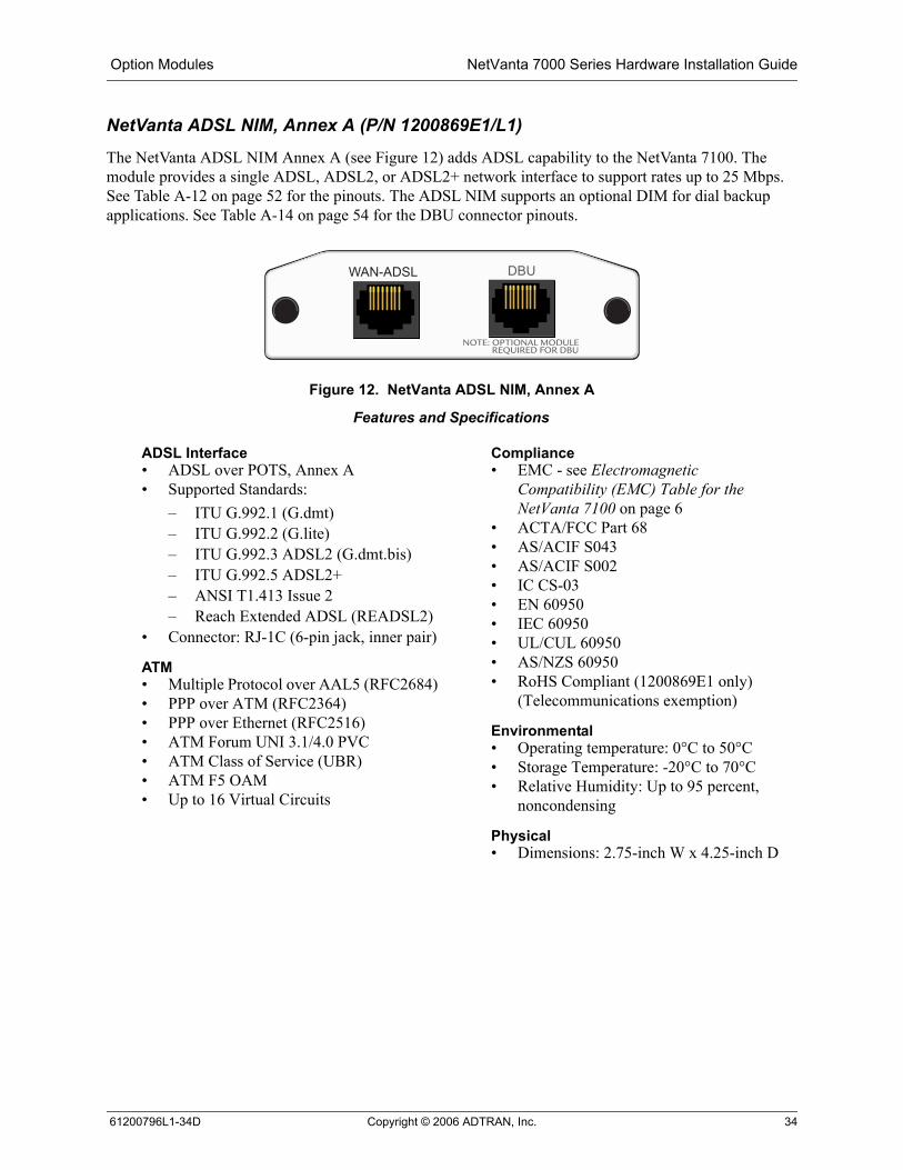
NetVanta ADSL NIM, Annex A (P/N 1200869E1/L1)
The NetVanta ADSL NIM Annex A (see Figure 12) adds ADSL capability to the NetVanta 7100. The module provides a single ADSL, ADSL2, or ADSL2+ network interface to support rates up to 25 Mbps. See Table A-12 on page 52 for the pinouts. The ADSL NIM supports an optional DIM for dial backup applications. See Table A-14 on page 54 for the DBU connector pinouts.
Figure 12. NetVanta ADSL NIM, Annex A
WAN-ADSL DBU
Features and Specifications
ADSL Interface• ADSL over POTS, Annex A • Supported Standards:
– ITU G.992.1 (G.dmt)– ITU G.992.2 (G.lite)– ITU G.992.3 ADSL2 (G.dmt.bis)– ITU G.992.5 ADSL2+ – ANSI T1.413 Issue 2– Reach Extended ADSL (READSL2)
• Connector: RJ-1C (6-pin jack, inner pair)
ATM• Multiple Protocol over AAL5 (RFC2684)• PPP over ATM (RFC2364)• PPP over Ethernet (RFC2516)• ATM Forum UNI 3.1/4.0 PVC• ATM Class of Service (UBR)• ATM F5 OAM• Up to 16 Virtual Circuits
Compliance • EMC - see Electromagnetic
Compatibility (EMC) Table for the NetVanta 7100 on page 6
• ACTA/FCC Part 68• AS/ACIF S043• AS/ACIF S002• IC CS-03• EN 60950• IEC 60950• UL/CUL 60950• AS/NZS 60950• RoHS Compliant (1200869E1 only)
(Telecommunications exemption)
Environmental • Operating temperature: 0°C to 50°C• Storage Temperature: -20°C to 70°C• Relative Humidity: Up to 95 percent,
noncondensing
Physical • Dimensions: 2.75-inch W x 4.25-inch D
61200796L1-34D Copyright © 2006 ADTRAN, Inc. 34
NetVanta 7000 Series Hardware Installation Guide Option Modules
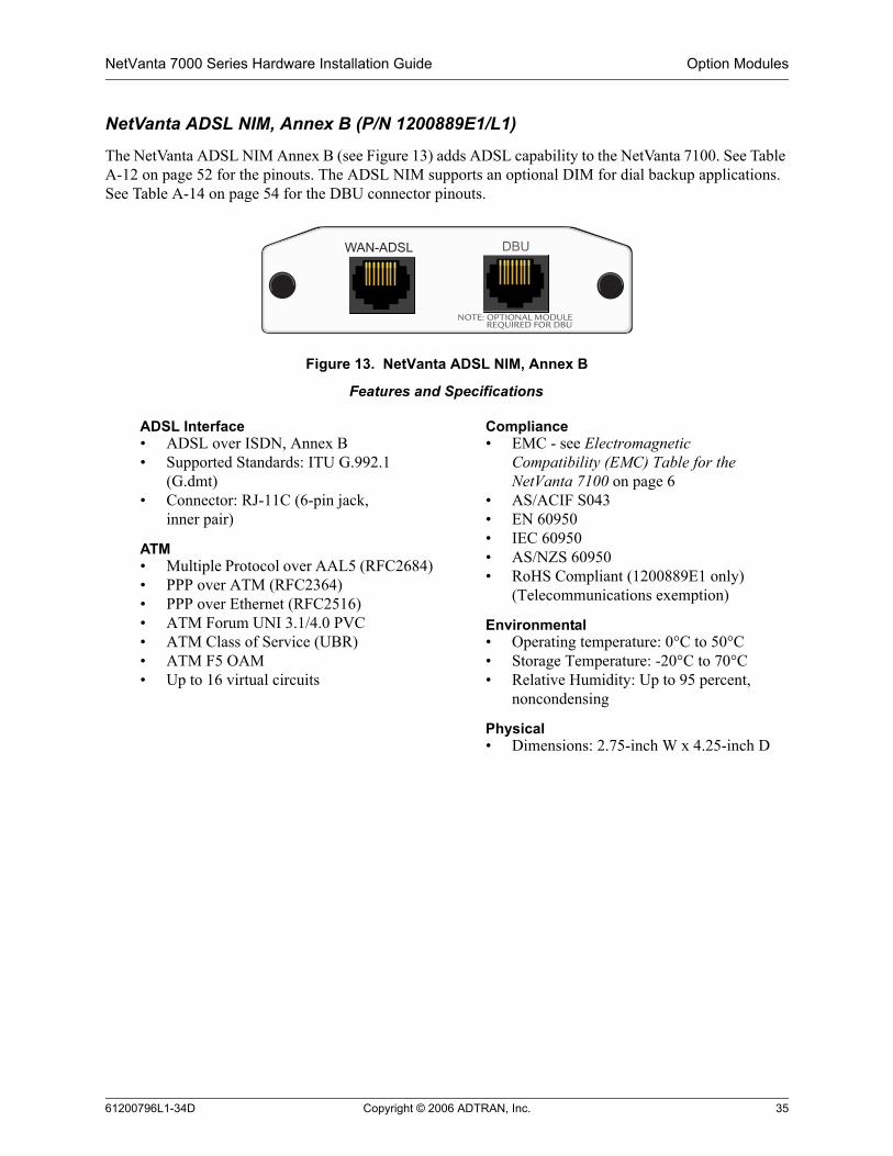
NetVanta ADSL NIM, Annex B (P/N 1200889E1/L1)
The NetVanta ADSL NIM Annex B (see Figure 13) adds ADSL capability to the NetVanta 7100. See Table A-12 on page 52 for the pinouts. The ADSL NIM supports an optional DIM for dial backup applications. See Table A-14 on page 54 for the DBU connector pinouts.
Figure 13. NetVanta ADSL NIM, Annex B
WAN-ADSL DBU
Features and Specifications
ADSL Interface • ADSL over ISDN, Annex B • Supported Standards: ITU G.992.1
(G.dmt)• Connector: RJ-11C (6-pin jack,
inner pair)
ATM• Multiple Protocol over AAL5 (RFC2684)• PPP over ATM (RFC2364)• PPP over Ethernet (RFC2516)• ATM Forum UNI 3.1/4.0 PVC• ATM Class of Service (UBR)• ATM F5 OAM• Up to 16 virtual circuits
Compliance • EMC - see Electromagnetic
Compatibility (EMC) Table for the NetVanta 7100 on page 6
• AS/ACIF S043• EN 60950• IEC 60950• AS/NZS 60950• RoHS Compliant (1200889E1 only)
(Telecommunications exemption)
Environmental • Operating temperature: 0°C to 50°C• Storage Temperature: -20°C to 70°C• Relative Humidity: Up to 95 percent,
noncondensing
Physical • Dimensions: 2.75-inch W x 4.25-inch D
61200796L1-34D Copyright © 2006 ADTRAN, Inc. 35

Option Modules NetVanta 7000 Series Hardware Installation Guide
NetVanta T1/PRI VIM, (P/N 1200695L1)
The NetVanta T1/PRI VIM (see Figure 14) adds T1 voice capability to the NetVanta 7100. Refer to Table A-7 on page 51 for the T1 connector pinouts.
Figure 14. NetVanta T1/PRI VIM
Features and Specifications
Operating Modes• Primary Rate ISDN (PRI), CAS
T1 Interface• Supported Standards: AT&T TR 62411,
AT&T TR54016, Bellcore TR 194, ANSI T1.403
• Line Rate: 1.544 Mbps +75 bps• Line Code: AMI or B8ZS• Framing: D4 (SF) or ESF• FT1 Line Rate: DS0 channelized
(multiples of 64 kbps)• Input Signal: 0 to -36 dB (DS1)• Line Build-Out: 0, -7.5, -15, -22.5 dB
(long), 0 to 655 ft (short)• DS0 Assignment: Programmable• Connector: RJ-48C
Clock Source• Line• Internal
Diagnostics• Test Pattern Generation and Detection:
QRSS, 215 - 1, all ones, all zeros• Network loopbacks (local and remote);
responds to both inband and FDL loop codes
• Alarm generation detection• Network performance data (15 minutes
and 24 hours)
Compliance• FCC Part 15 Class A, EN 55022 Class A• ACTA/FCC Part 68• IC CS-03• UL/CUL 60950
Environmental • Operating temperature: 0°C to 50°C• Storage Temperature: -20°C to 70°C• Relative Humidity: Up to 95 percent,
noncondensing
Physical • Dimensions: 2.75-inch W x 4.25-inch D
61200796L1-34D Copyright © 2006 ADTRAN, Inc. 36

NetVanta 7000 Series Hardware Installation Guide Option Modules
NetVanta Quad FXS VIM, (P/N 1200690E1/L1)
The NetVanta Quad FXS VIM (see Figure 15) adds voice capability to the NetVanta 7100. Refer toTable A-4 on page 50 for the FXS connector pinouts.
Figure 15. NetVanta Quad FXS VIM,
ANALOGVIM
STATIONS
1 2 3 4
Features and Specifications
Analog Voice Ports • Loop Start (LS), Ground Start (GS)• Normal and reverse battery operation
Transmission Level• FXS Receive Gain: -12 to +6 dB,
0.1 dB steps• FXS Transmit Gain: -12 to +6 dB,
0.1 dB steps
Compliance • UL 60950, Third Edition/CSA C22.2,
No.60950• FCC Part 15 Class A• RoHS Compliant (1200690E1 only)
(Telecommunications exemption)
Environmental • Operating temperature: 0°C to 50°C• Storage Temperature: -20°C to 70°C• Relative Humidity: Up to 95 percent,
noncondensing
Physical • Dimensions: 2.75-inch W x 4.25-inch D
61200796L1-34D Copyright © 2006 ADTRAN, Inc. 37

Option Modules NetVanta 7000 Series Hardware Installation Guide
NetVanta Quad FXO VIM, (P/N 1200691E1/L1)
The NetVanta Quad FXO VIM (see Figure 16) adds voice capability to the NetVanta 7100. Refer toTable A-4 on page 50 for the FXO connector pinouts.
Figure 16. NetVanta Quad FXO VIM
ANALOGVIM
TRUNKS
1 2 3 4
Features and Specifications
Analog Voice Ports • Loop Start (LS), Ground Start (GS)• Normal and reverse battery operation
Transmission Level• FXO Transmit Gain: -6 to +10 dB,
0.1 dB steps• FXO Receive Gain: -6 to +10 dB,
0.1 dB steps
Compliance • UL 60950, Third Edition/CSA C22.2,
No.60950• FCC Part 15 Class A and Part 68• RoHS Compliant (1200691E1 only)
(Telecommunications exemption)
Environmental • Operating temperature: 0°C to 50°C• Storage Temperature: -20°C to 70°C• Relative Humidity: Up to 95 percent,
noncondensing
Physical • Dimensions: 2.75-inch W x 4.25-inch D
61200796L1-34D Copyright © 2006 ADTRAN, Inc. 38

NetVanta 7000 Series Hardware Installation Guide Option Modules
NetVanta Dual FXS/FXO VIM, (P/N 1200692E1/L1)
The NetVanta Dual FXS/FXO VIM (see Figure 17) adds voice capability to the NetVanta 7100. Refer to Table A-4 on page 50 for the FXS/FXO connector pinouts.
Figure 17. NetVanta Dual FXS/FXO VIM
Devices connected to the Station (FXS) ports must be ACTA/FCC Part 68 compliant due to the direct connection to the PSTN in Life Line mode.
ANALOGVIM
TRUNKSSTATIONS
1 2 1 2
Features and Specifications
Analog Voice Ports• Dual FXS and Dual FXO ports• Loop Start (LS), Ground Start (GS)• Normal and reverse battery operation
Transmission Level• FXS Receive Gain: -12 to +6 dB,
0.1 dB steps• FXS Transmit Gain: -12 to +6 dB,
0.1 dB steps• FXO Transmit Gain: -6 to +10 dB,
0.1 dB steps• FXO Receive Gain: -6 to +10 dB,
0.1 dB steps
Compliance • UL 60950, Third Edition/CSA C22.2,
No.60950• FCC Part 15 Class A and Part 68• RoHS Compliant (1200692E1 only)
(Telecommunications exemption)
Environmental • Operating temperature: 0°C to 50°C• Storage Temperature: -20°C to 70°C• Relative Humidity: Up to 95 percent,
noncondensing
Physical • Dimensions: 2.75-inch W x 4.25-inch D
61200796L1-34D Copyright © 2006 ADTRAN, Inc. 39
Option Modules NetVanta 7000 Series Hardware Installation Guide
Dial Backup Interface Modules
NetVanta Analog Modem DIM (P/N 1200864L1)
The Analog Modem DIM provides a modem with data rates up to 33.6 kbps for the NetVanta 7100. This DIM is a plug-on card that connects to the NIM. For installation instructions, refer to Installing Dial Backup and Network Interface Modules on page 47.
Features and Specifications
Features• Supported Standards: ITU V.90• Async
Compliance• EMC - see Electromagnetic Compatibility (EMC) Table for the NetVanta 7100 on page 6.• ACTA/FCC Part 68• IC CS-03• UL/CUL 60950
Environmental• Operating Temperature: 0°C to 50°C• Storage Temperature: -20°C to 70°C• Relative Humidity: Up to 95 percent, noncondensing
Physical• Dimensions: 2.5-inch W x 3.75-inch D
61200796L1-34D Copyright © 2006 ADTRAN, Inc. 40
NetVanta 7000 Series Hardware Installation Guide Option Modules
NetVanta ISDN BRI DIM (P/N 1200865L1)
The NetVanta ISDN BRI DIM provides dial backup access to the public switched telephone network (PSTN) via Basic Rate ISDN for the NetVanta 7100. This DIM is a plug-on module that connects to the NIM. For installation instructions, refer to Installing Dial Backup and Network Interface Modules on page 47.
Features and Specifications
Features• Clear Channel and bonding mode 1 call protocols• Network support for 64 kbps (1 B-channel) or 128 kbps (2 B-channels)• D-channel switch compatibility with AT&T 5ESS, Northern Telecom DMS-100, and National
ISDN-1• V.54 network loopback support
Compliance• EMC - see Electromagnetic Compatibility (EMC) Table for the NetVanta 7100 on page 6.• ACTA/FCC Part 68• IC CS-03• UL/CUL 60950
Environmental• Operating Temperature: 0°C to 50°C• Storage Temperature: -20°C to 70°C• Relative Humidity: Up to 95 percent, noncondensing
Physical• Dimensions: 2.5-inch W x 3.75-inch D
61200796L1-34D Copyright © 2006 ADTRAN, Inc. 41

Option Modules NetVanta 7000 Series Hardware Installation Guide
NetVanta ISDN S/T DIM (P/N 1200875L1)
The NetVanta ISDN S/T DIM provides dial backup access to the public switched telephone network (PSTN) via Basic Rate ISDN for the NetVanta 7100. This DIM is a plug-on module that connects to the NIM. For installation instructions, see Installing Dial Backup and Network Interface Modules on page 47.
Features and Specifications
Features• Clear channel and bonding mode 1 call protocols• Network support for 64 kbps (1 B-channel) or 128 kbps (2 B-channels)• D-channel switch compatibility with AT&T 5ESS, Northern Telecom DMS-100, National ISDN-1,
and Euro-ISDN• V.54 network loopback support
Compliance• EMC - see Electromagnetic Compatibility (EMC) Table for the NetVanta 7100 on page 6.• AS/ACIF S031• ETSI TBR 3• EN 60950• IEC 60950• AS/NZS 60950
Environmental• Operating Temperature: 0°C to 50°C• Storage Temperature: -20°C to 70°C• Relative Humidity: Up to 95 percent, noncondensing
Physical• Dimensions: 2.5-inch W x 3.75-inch D
61200796L1-34D Copyright © 2006 ADTRAN, Inc. 42

NetVanta 7000 Series Hardware Installation Guide Unit Installation
5. UNIT INSTALLATION
The instructions and guidelines provided in this section cover hardware installation topics such as mounting options, supplying power to the unit, and installing option cards. These instructions are presented as follows:• Mounting Options on page 44• Supplying Power to the Unit on page 46• Installing Dial Backup and Network Interface Modules on page 47
For information on configuring a specific application, refer to the quick configuration documents provided on your ADTRAN OS System Documentation CD or the Command Line Reference Guide (also included on your CD).
Tools Required
The customer-provided tools required for the hardware installation of the NetVanta 7100 are:• Ethernet cables• Network cables (module dependent)• DSX-1 cable (T1/FT1 + DSX-1 module only)• DBU cable (dial backup functions require an optional DIM)• Phillips-head screwdriver
To prevent electrical shock, do not install equipment in a wet location or during a lightning storm.
Electronic modules can be damaged by static electrical discharge. Before handling modules, put on an antistatic discharge wrist strap to prevent damage to electrical components. Place modules in antistatic packing material when transporting or storing. When working on modules, always place them on an approved antistatic mat that is electrically grounded.
To access the command line interface (CLI) of the NetVanta 7100, you will also need a VT100 terminal or PC with terminal emulation software and a console port cable. Instructions on how to access the CLI are given in the Command Reference Guide (provided on the ADTRAN OS System Documentation CD).
61200796L1-34D Copyright © 2006 ADTRAN, Inc. 43

Unit Installation NetVanta 7000 Series Hardware Installation Guide
Mounting Options
The unit may be installed in rackmount, wallmount, or tabletop configurations. The following sections provide step-by-step instructions for rack mounting and wall mounting.
Rack Mounting the NetVanta 7100
The NetVanta is a 1U-high, rack-mountable unit which can be installed into a 19-inch equipment rack. The following steps guide you in mounting the NetVanta 7100 into a rack.
Instructions for Rack Mounting the NetVanta
Step Action
1 Attach the rackmount ears with the screws and brackets supplied in the Rackmount Kit.
2 To allow proper grounding, scrape the paint from the rack around the mounting holes where the NetVanta 7100 will be positioned.
3 Position the NetVanta 7100 in a stationary equipment rack. This unit occupies 1U of space.
4 Have an assistant hold the unit in position as you install two mounting bolts through the unit’s brackets and into the equipment rack using a #2 phillips-head screwdriver.
5 Apply power to the unit (refer to Supplying Power to the Unit on page 46).
Be careful not to compromise the stability of the equipment mounting rack when installing this product.
61200796L1-34D Copyright © 2006 ADTRAN, Inc. 44

NetVanta 7000 Series Hardware Installation Guide Unit Installation
Wall Mounting the NetVanta
By following these instructions exactly, the NetVanta can be safely mounted to the wall.
Figure 18. Wallmount Installation
Instructions for Wall Mounting the NetVantaStep Action
1 Attach the rackmount ears with the screws and brackets supplied in the Rackmount Kit.2 Remove the mounting ears. Rotate them 90 degrees so that the portion of the bracket with the
mounting holes is flush with the bottom of the chassis. Reattach the mounting ears to the chassis (see Figure 18 on page 45).
3 Decide on a location for the NetVanta 7100. Keep in mind that the unit needs to be mounted at or below eye-level so that the LEDs are viewable.
4 Prepare the mounting surface by attaching a board (typically plywood, 3/ 4-inch to 1-inch thick) to a wall stud.
Important! Mounting to a stud ensures stability. Using sheetrock anchors may not provide sufficient long-term stability.
5 Have an assistant hold the unit in position as you install two #6 to #10 (1 1/ 2 inches or greater in length) wood screws through the unit’s brackets and into the mounted board (see Figure 18).
6 Proceed to the steps given in Supplying Power to the Unit on page 46.
To avoid damaging the unit, use only the screws included in the shipment when attaching mounting ears to the chassis.
61200796L1-34D Copyright © 2006 ADTRAN, Inc. 45

Unit Installation NetVanta 7000 Series Hardware Installation Guide
Supplying Power to the Unit
The NetVanta 7100 unit comes equipped with an auto-sensing 100 to 250 VAC, 50/60 Hz power supply for connecting to a properly grounded power receptacle. (A detachable power cable with a grounded, three-prong plug comes with the shipment.) To power these units, connect the power cable to an appropriate AC power source.
61200796L1-34D Copyright © 2006 ADTRAN, Inc. 46

NetVanta 7000 Series Hardware Installation Guide Unit Installation
Installing Dial Backup and Network Interface Modules
The DIM plugs on to the NIM. The NIM is then installed into the rear panel option module slot. The following tables list the installation steps. Also see Figure 19 on page 47 and Figure 20 on page 48.
Figure 19. Installing DIMs
For NetVanta modules with outside plant connections, ensure that all cables are removed from the module before installing or removing it from the NetVanta chassis.
Always remove power from the unit and all telecommunication connections prior to removing or installing a module.
Improper installation may result in damage to the modules.
Instructions for Installing the DIMs
Step Action
1 Remove power from the unit.
2 If the NIM/VIM is already in the NetVanta chassis, remove all cables, release the pins at both edges of the NIM front panel and slide the module out of the chassis.
3 Align the P1 connector on the NIM/VIM with the J1 connector on the DIM. Using only fingertip pressure so that neither circuit board bends or flexes, ensure that the connectors are firmly seated. Secure the DIM to the NIM/VIM using the screws and standoff posts supplied. See Figure 19.
4 Slide the NIM/VIM with the DIM attached into the NetVanta chassis, continuing with the normal NIM installation (refer to Instructions for Installing the NIMs and VIMs on page 48).
61200796L1-34D Copyright © 2006 ADTRAN, Inc. 47

Unit Installation NetVanta 7000 Series Hardware Installation Guide
Figure 20. NIM/VIM and DIM Installation
Your NetVanta 7100 is now ready to be configured and connected to the network. For more information on configuration for a specific application, refer to the quick configuration documents provided on your ADTRAN OS System Documentation CD. For details on the command line interface, refer to the Command Reference Guide (also included on your CD).
Instructions for Installing the NIMs and VIMs
Step Action
1 Remove power from the unit.
2 Slide the option module into the option slot until the module is firmly seated against the chassis.
3 Secure the pins at both edges of the module.
4 Connect the cables to the associated device(s).
5 Restore power to the unit.
All unused NIM/VIM slots on the back panel of the unit must be covered with the supplied cover plates.
CF
SLOT 1 NIM/VIM SLOT 2 NIM/VIM STATIONS TRUNKS
ANALOGFXS FXO
0/1 0/2 0/1 0/2
MOH
NO NC COM
ETH 0/0 CONSOLEDOORRELAY
100-250 VAC�50-60Hz
PAGE
61200796L1-34D Copyright © 2006 ADTRAN, Inc. 48

APPENDIX A. CONNECTOR PIN DEFINITIONSThe following tables provide the pin assignments for the base unit, network interface modules (NIMs), voice interface modules (VIMs), and dial backup interface modules (DIMs).
Base Unit Pinouts
Table A-1. CONSOLE Port Pinouts
Pin Name Description
1 DCD Data Carrier Detect (output)
2 RD Receive Data (output)
3 TD Transmit Data (input)
4 DTR Data Terminal Ready (input)
5 SG Signal Ground
6 DSR Data Set Ready Tied to pin 1 (output)
7 — Unused
8 CTS Clear to Send Tied to pin 1 (output)
9 — Unused
Table A-2. 10/100BaseT Ethernet Port Pinouts
Pin Name Description
1 TX1 Transmit Positive
2 TX2 Transmit Negative
3 RX1 Receive Positive
4, 5 — Unused
6 RX2 Receive Negative
7, 8 — Unused
61200796L1-34D Copyright © 2006 ADTRAN, Inc. 49

Appendix A. Connector Pin Definitions NetVanta 7000 Series Hardware Installation Guide
Table A-4. Analog - Onboard FXS and FXO Port Pinouts
Table A-5. Alarm Contacts
Table A-3. 1000BaseT Gigabit-Ethernet Port Pinouts
Pin Name Description
1 TRD0+ Transmit/Receive Positive
2 TRD0- Transmit/Receive Negative
3 TRD1+ Transmit/Receive Positive
4 TRD2+ Transmit/Receive Positive
5 TRD2- Transmit/Receive Negative
6 TRD1- Transmit/Receive Negative
7 TRD3+ Transmit/Receive Positive
8 TRD3- Transmit/Receive Negative
Pin Name Description
1,2 — Unused
3 Ring Ring lead of the 2-wire interface
4 Tip Tip lead of the 2-wire interface
5,6 — Unused
Pin Name Description
NO Normally Open
NC Normally Closed
COM Common
50 Copyright © 2006 ADTRAN, Inc. 61200796L1-34D

NetVanta 7000 Series Hardware Installation Guide Appendix A. Connector Pin Definitions
Network Interface Module Pinouts
Table A-6. WAN-DDS Connector Pinouts
Pin Name Description
1 R1 Transmit data to the network–Ring 1
2 T1 Transmit data to the network–Tip 1
3-6 — Unused
7 T Receive data from the network–Tip
8 R Receive data from the network–Ring
Table A-7. WAN-T1 Connector Pinouts
Pin Name Description
1 R1 Receive data from the network–Ring 1
2 T1 Receive data from the network–Tip 1
3 — Unused
4 R Transmit data toward the network–Ring
5 T Transmit data toward the network–Tip
6-8 — Unused
Table A-8. WAN-E1 Connector Pinouts
Pin Name Description
1 R1 Receive data from the network–Ring 1
2 T1 Receive data from the network–Tip 1
3 — Unused
4 R Transmit data toward the network–Ring
5 T Transmit data toward the network–Tip
6-8 — Unused
61200796L1-34D Copyright © 2006 ADTRAN, Inc. 51

Appendix A. Connector Pin Definitions NetVanta 7000 Series Hardware Installation Guide
Table A-9. DSX-1 Connector Pinouts
Pin Name Description
1 R Transmit data toward the DTE–Ring
2 T Transmit data toward the DTE–Tip
3 — Unused
4 R1 Receive data from the DTE–Ring 1
5 T1 Receive data from the DTE–Tip 1
6-8 — Unused
Table A-10. G.703 Connector Pinouts
Pin Name Description
1 R Transmit data toward the DTE–Ring
2 T Transmit data toward the DTE–Tip
3 — Unused
4 R1 Receive data from the DTE–Ring 1
5 T1 Receive data from the DTE–Tip 1
6-8 — Unused
Table A-11. WAN-SHDSL Connector Pinouts
Pin Name Description
1-3 — Unused
4 T Transmit data toward the network–Tip
5 R Transmit data toward the network–Ring
6-8 — Unused
Table A-12. WAN-ADSL Connector Pinouts
Pin Name Description
1, 2 — Unused
3 R ADSL Ring
4 T ADSL Tip
5, 6 — Unused
52 Copyright © 2006 ADTRAN, Inc. 61200796L1-34D
NetVanta 7000 Series Hardware Installation Guide Appendix A. Connector Pin Definitions
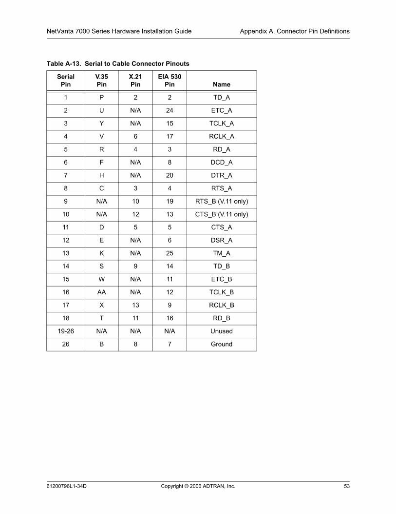
Table A-13. Serial to Cable Connector Pinouts
SerialPin
V.35Pin
X.21Pin
EIA 530Pin Name
1 P 2 2 TD_A
2 U N/A 24 ETC_A
3 Y N/A 15 TCLK_A
4 V 6 17 RCLK_A
5 R 4 3 RD_A
6 F N/A 8 DCD_A
7 H N/A 20 DTR_A
8 C 3 4 RTS_A
9 N/A 10 19 RTS_B (V.11 only)
10 N/A 12 13 CTS_B (V.11 only)
11 D 5 5 CTS_A
12 E N/A 6 DSR_A
13 K N/A 25 TM_A
14 S 9 14 TD_B
15 W N/A 11 ETC_B
16 AA N/A 12 TCLK_B
17 X 13 9 RCLK_B
18 T 11 16 RD_B
19-26 N/A N/A N/A Unused
26 B 8 7 Ground
61200796L1-34D Copyright © 2006 ADTRAN, Inc. 53

Appendix A. Connector Pin Definitions NetVanta 7000 Series Hardware Installation Guide
Dial Backup Interface Module Pinouts (DBU Connector)
Table A-14. DBU Connector Pinouts
Pin Name Description
1-3 — Unused
4 R Network–Ring
5 T Network–Tip
6-8 — Unused
An optional DIM is required for dial backup applications.
54 Copyright © 2006 ADTRAN, Inc. 61200796L1-34D

Index
Numerics56K/64K NIM 25
AADSL NIM, Annex A 34ADSL NIM, Annex B 35, 38alarm contacts, door relay contacts 19analog stations 17analog trunks 17
Ccommand line interface 43Compact Flash 17connecting to an external modem 23console port description 23customer service 8, 18
Ddata applications 17Dial Backup Interface Modules
Analog Modem card 40ISDN BRI card 41ISDN S/T card 42
DIMs, installing 47Dual 39dual T1 NIM 29
EE1/FE1 30E1/FE1 + G.703 Drop 31EMC table 6external modem, connecting to 23
Ffront panel
description 21LEDs 22
GGigabit Ethernet interfaces 21
Iinstallation
rack mounting instructions 44wall mounting instructions 45
installing DIMs 47installing NIMs 48installing the unit 43
LLEDs, description of 21, 22
NNetVanta 7100, brief description 17
Network Interface Modules56K/64K module 25ADSL module, Annex A 34ADSL module, Annex B 35, 38Dual T1 module 29E1/FE1 + G.703 module 31E1/FE1 module 30Serial module 32SHDSL module 33T1/FT1 + DSX-1 module 28T1/FT1 module 26T1/FT1 NEBS module 27
NIMs, installing 48
Ooption modules discussion 24
Pphysical description of products 18pinouts
10/100BaseT ports 491000BaseT ports 50ADSL interface 52DDS interface 51DSX-1 Interface 52E1 interface 51G.703 interface 52SHDSL interface 52T1 interface 51
power over ethernet 18power, supplying to unit 46product overview 18product registration 8product specifications 19
Rrack mounting instructions 44rear panel 23
Ssafety instructions 4serial NIM 32SHDSL interface 33SHDSL NIM 33shipment
contents of 18damage during transit 18inspection of 18
TT1, dual module 29T1/FT1 + DSX-1 module 28T1/FT1 module 26T1/FT1 NEBS module 27tools required for installation 43
61200796L1-34D Copyright © 2006 ADTRAN, Inc. 55

Index NetVanta 7100 Series Hardware Installation Guide
Vvoice applications 17Voice Interface Modules
Dual FXS/FXO VIM 39Quad FXO VIM 38Quad FXS VIM 37T1/PRI VIM 36
Wwall mounting instructions 45warranty 8
56 Copyright © 2006 ADTRAN, Inc. 61200796L1-34D