NET323 D: NETWORKS PROTOCOLSRouting Table 5 For a network router to know where to send packets of...
36
NET323 D: NETWORKS PROTOCOLS Lab # 3 : Router Configuration Networks and Communication Systems Department TA. Anfal AlHazzaa 1
Transcript of NET323 D: NETWORKS PROTOCOLSRouting Table 5 For a network router to know where to send packets of...
NET323 D:
NETWORKS PROTOCOLS
Lab # 3 : Router Configuration Networks and Communication
Systems Department
TA. Anfal AlHazzaa
1
Lab Objectives 2
To connect two small LANs using Router
To configure router interfaces
To send ICMP message between devices in
different networks
Networks and Communication Systems Department – Prepared By: TA. Anfal AlHazzaa
Lab Content
What is the router?
Routing Table
CLI ( Command Line Interface)
CLI (Command Line Interface) Modes
CLI navigation (example)
Scenario (Connecting two LANs using router)
What is gateway?
3
Networks and Communication Systems Department – Prepared By: TA. Anfal AlHazzaa
What is Router?
4
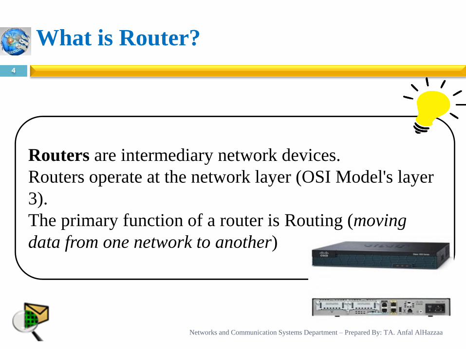
Routers are intermediary network devices.
Routers operate at the network layer (OSI Model's layer
3).
The primary function of a router is Routing (moving
data from one network to another)
Networks and Communication Systems Department – Prepared By: TA. Anfal AlHazzaa
Routing Table
5
For a network router to know where to send packets
of data it receives, it uses a routing table.
The routing table contains a list of specific routing
destinations, and when the router receives a packet of
data, it references the routing table to know where to
send that data.
The routing table may also contain information on
how far each destination is from the router. In essence,
a routing table is a map for the router.
Networks and Communication Systems Department – Prepared By: TA. Anfal AlHazzaa
CLI ( Command Line Interface)
6
These are the basic modes of a router, which are recognized by the symbols shown in the table (in next slide)
A user needs to know
Which mode he is in.
What are the various commands that he can type in that mode
How to navigate between different modes of a router.
Networks and Communication Systems Department – Prepared By: TA. Anfal AlHazzaa
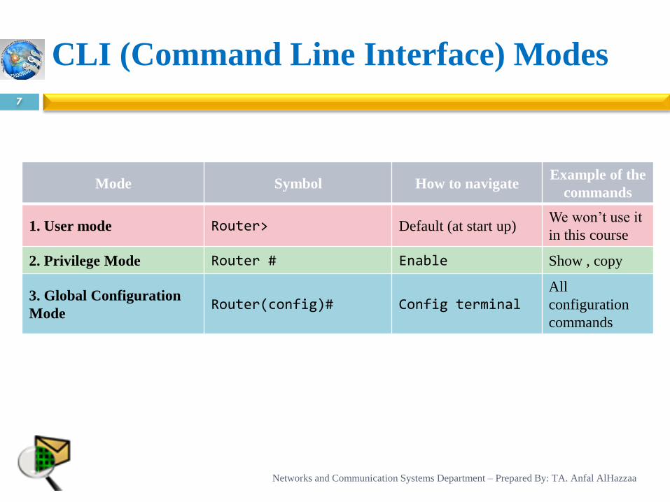
CLI (Command Line Interface) Modes
7
Mode Symbol How to navigate Example of the
commands
1. User mode Router> Default (at start up) We won’t use it
in this course
2. Privilege Mode Router # Enable Show , copy
3. Global Configuration
Mode Router(config)# Config terminal
All
configuration
commands
Networks and Communication Systems Department – Prepared By: TA. Anfal AlHazzaa
Note
8
If a user is not sure of what are the commands to be
typed in any mode then he can type the “?” Symbol to
get help, or the list of Commands to be typed in that mode
Networks and Communication Systems Department – Prepared By: TA. Anfal AlHazzaa
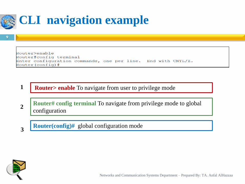
CLI navigation example
9
Router> enable To navigate from user to privilege mode
Router# config terminal To navigate from privilege mode to global
configuration
Router(config)# global configuration mode
2
1
3
Networks and Communication Systems Department – Prepared By: TA. Anfal AlHazzaa
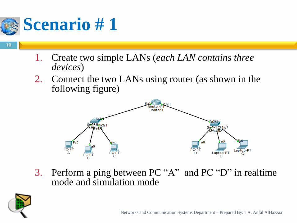
Scenario # 1 10
1. Create two simple LANs (each LAN contains three devices)
2. Connect the two LANs using router (as shown in the following figure)
3. Perform a ping between PC “A” and PC “D” in realtime mode and simulation mode
Networks and Communication Systems Department – Prepared By: TA. Anfal AlHazzaa
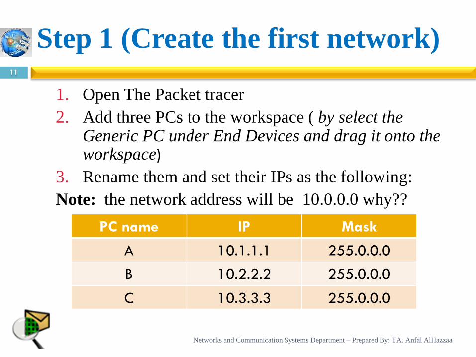
1. Open The Packet tracer
2. Add three PCs to the workspace ( by select the Generic PC under End Devices and drag it onto the workspace)
3. Rename them and set their IPs as the following:
Note: the network address will be 10.0.0.0 why??
Step 1 (Create the first network) 11
PC name IP Mask
A 10.1.1.1 255.0.0.0
B 10.2.2.2 255.0.0.0
C 10.3.3.3 255.0.0.0
Networks and Communication Systems Department – Prepared By: TA. Anfal AlHazzaa
Step 1 (Create the first network) cont.
12
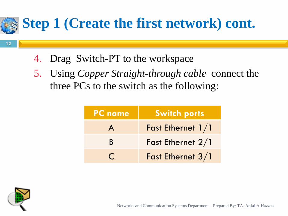
4. Drag Switch-PT to the workspace
5. Using Copper Straight-through cable connect the
three PCs to the switch as the following:
PC name Switch ports
A Fast Ethernet 1/1
B Fast Ethernet 2/1
C Fast Ethernet 3/1
Networks and Communication Systems Department – Prepared By: TA. Anfal AlHazzaa
Step 1 (Create the first network) cont.
13
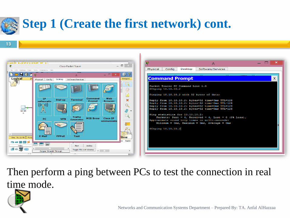
Then perform a ping between PCs to test the connection in real
time mode.
Networks and Communication Systems Department – Prepared By: TA. Anfal AlHazzaa
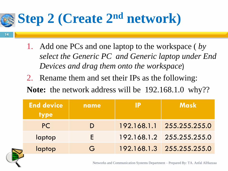
1. Add one PCs and one laptop to the workspace ( by
select the Generic PC and Generic laptop under End
Devices and drag them onto the workspace)
2. Rename them and set their IPs as the following:
Note: the network address will be 192.168.1.0 why??
Step 2 (Create 2nd network) 14
End device
type
name IP Mask
PC D 192.168.1.1 255.255.255.0
laptop E 192.168.1.2 255.255.255.0
laptop G 192.168.1.3 255.255.255.0
Networks and Communication Systems Department – Prepared By: TA. Anfal AlHazzaa
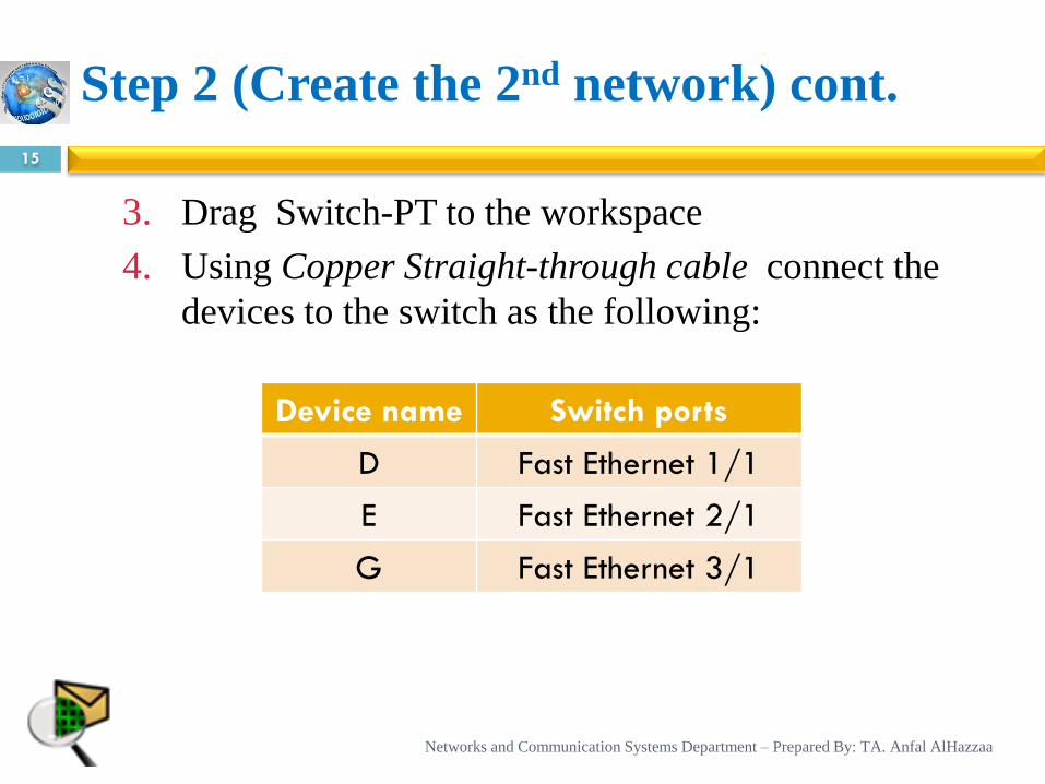
Step 2 (Create the 2nd network) cont.
15
3. Drag Switch-PT to the workspace
4. Using Copper Straight-through cable connect the
devices to the switch as the following:
Device name Switch ports
D Fast Ethernet 1/1
E Fast Ethernet 2/1
G Fast Ethernet 3/1
Networks and Communication Systems Department – Prepared By: TA. Anfal AlHazzaa
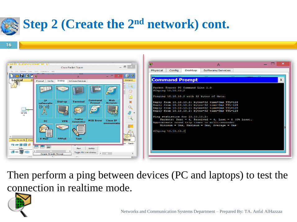
Step 2 (Create the 2nd network) cont.
16
Then perform a ping between devices (PC and laptops) to test the
connection in realtime mode.
Networks and Communication Systems Department – Prepared By: TA. Anfal AlHazzaa
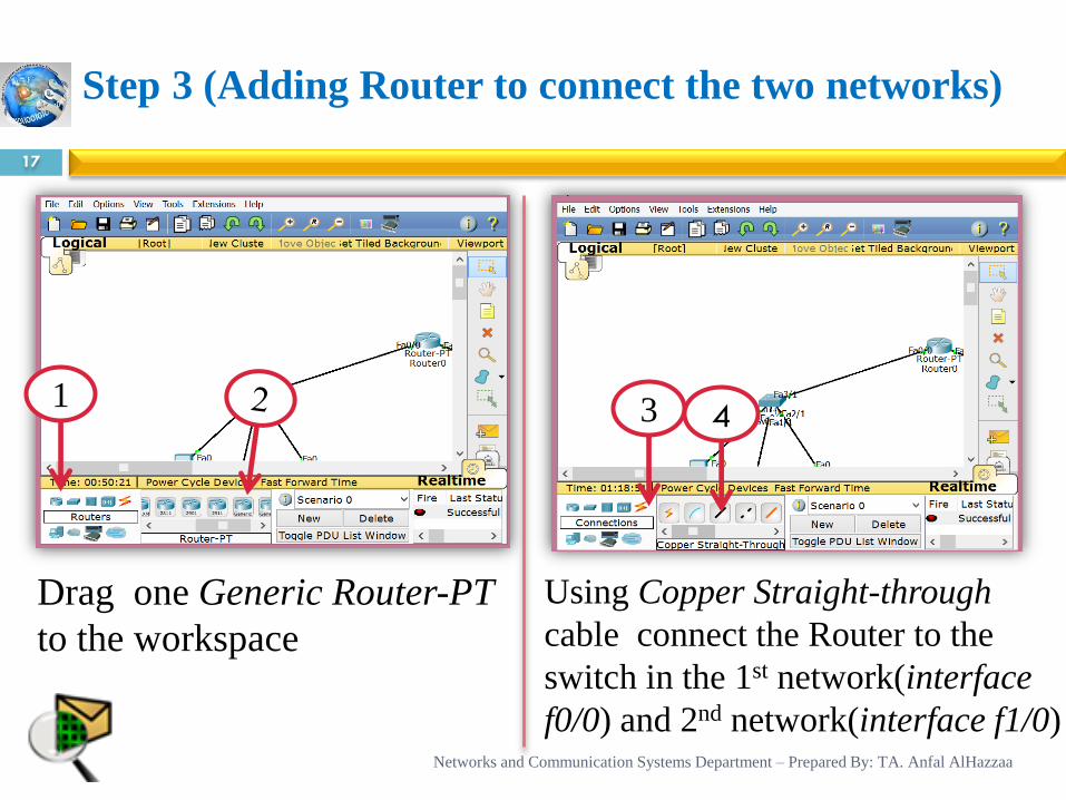
Step 3 (Adding Router to connect the two networks)
17
3 4 1
Drag one Generic Router-PT
to the workspace
Using Copper Straight-through
cable connect the Router to the
switch in the 1st network(interface
f0/0) and 2nd network(interface f1/0) Networks and Communication Systems Department – Prepared By: TA. Anfal AlHazzaa
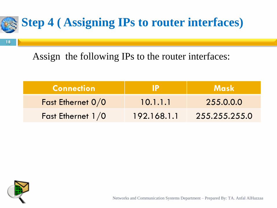
Assign the following IPs to the router interfaces:
Step 4 ( Assigning IPs to router interfaces)
18
Connection IP Mask
Fast Ethernet 0/0 10.1.1.1 255.0.0.0
Fast Ethernet 1/0 192.168.1.1 255.255.255.0
Networks and Communication Systems Department – Prepared By: TA. Anfal AlHazzaa
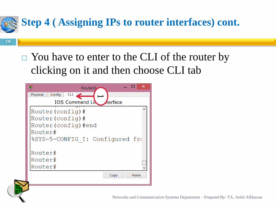
Step 4 ( Assigning IPs to router interfaces) cont.
19
You have to enter to the CLI of the router by
clicking on it and then choose CLI tab
1
Networks and Communication Systems Department – Prepared By: TA. Anfal AlHazzaa
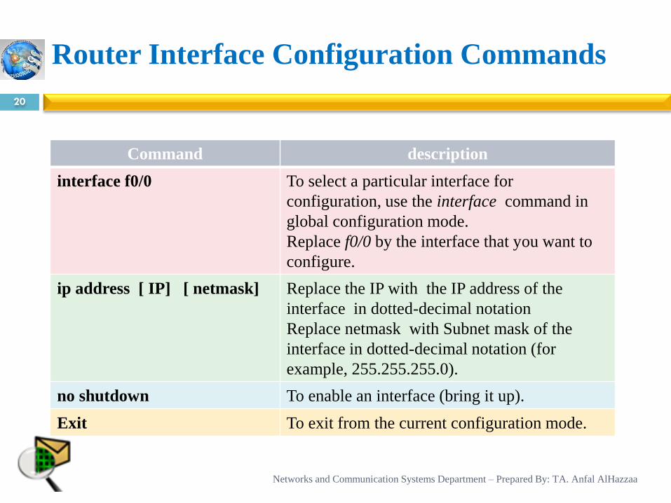
Router Interface Configuration Commands
20
Command description
interface f0/0 To select a particular interface for
configuration, use the interface command in
global configuration mode.
Replace f0/0 by the interface that you want to
configure.
ip address [ IP] [ netmask] Replace the IP with the IP address of the
interface in dotted-decimal notation
Replace netmask with Subnet mask of the
interface in dotted-decimal notation (for
example, 255.255.255.0).
no shutdown To enable an interface (bring it up).
Exit To exit from the current configuration mode.
Networks and Communication Systems Department – Prepared By: TA. Anfal AlHazzaa
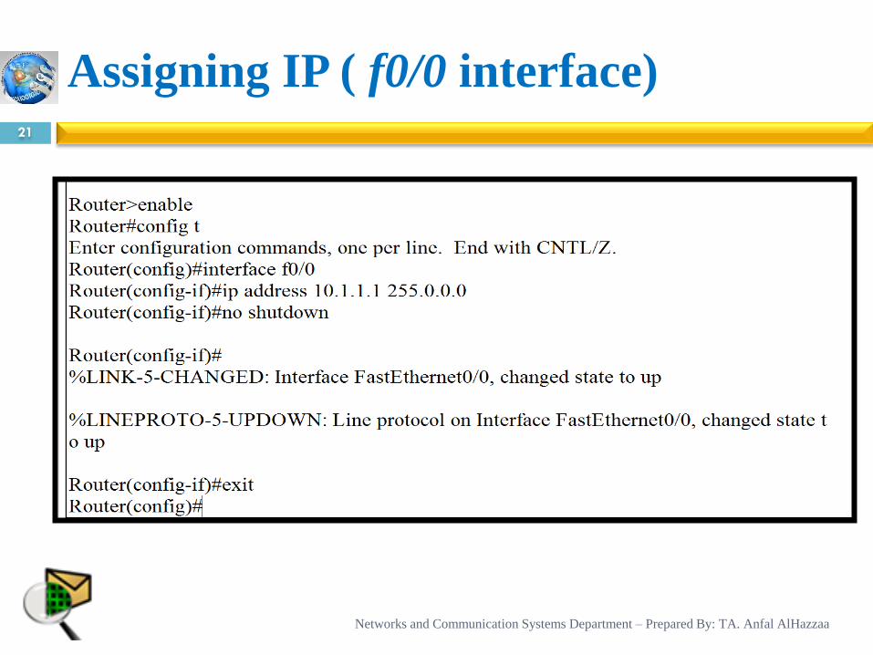
Assigning IP ( f0/0 interface) 21
Networks and Communication Systems Department – Prepared By: TA. Anfal AlHazzaa
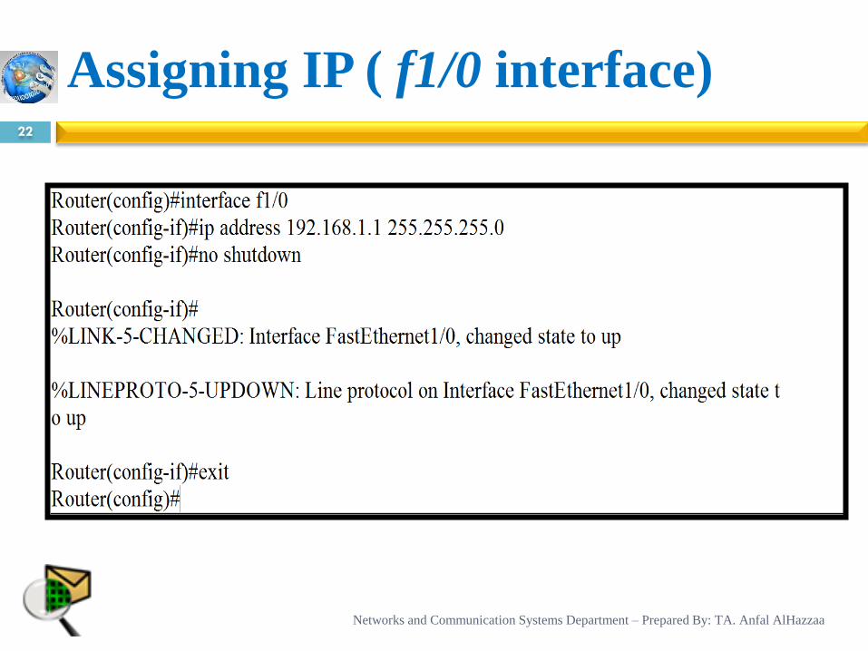
Assigning IP ( f1/0 interface) 22
Networks and Communication Systems Department – Prepared By: TA. Anfal AlHazzaa
Note
23
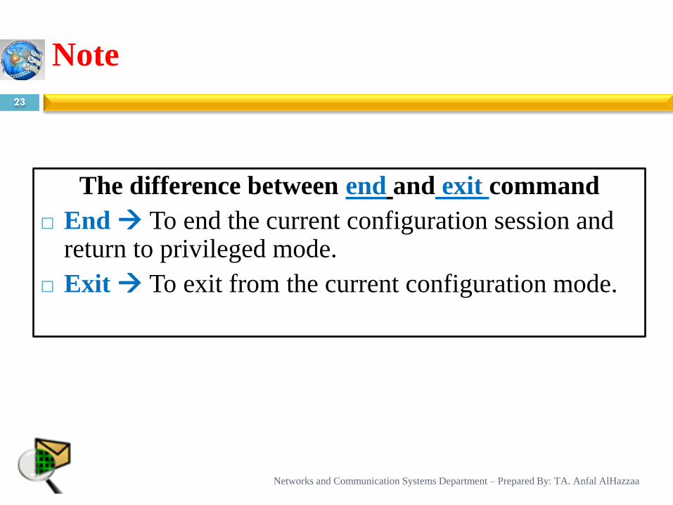
The difference between end and exit command
End To end the current configuration session and return to privileged mode.
Exit To exit from the current configuration mode.
Networks and Communication Systems Department – Prepared By: TA. Anfal AlHazzaa
Gateway
24
Gateway is a network point that acts as an
entrance to another network.
Networks and Communication Systems Department – Prepared By: TA. Anfal AlHazzaa
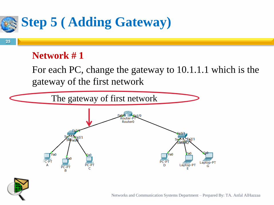
Network # 1
For each PC, change the gateway to 10.1.1.1 which is the
gateway of the first network
Step 5 ( Adding Gateway)
25
The gateway of first network
Networks and Communication Systems Department – Prepared By: TA. Anfal AlHazzaa
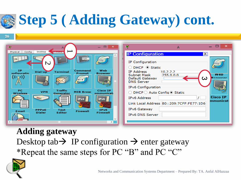
Step 5 ( Adding Gateway) cont. 26
1
3
Adding gateway
Desktop tab IP configuration enter gateway
*Repeat the same steps for PC “B” and PC “C”
2
Networks and Communication Systems Department – Prepared By: TA. Anfal AlHazzaa
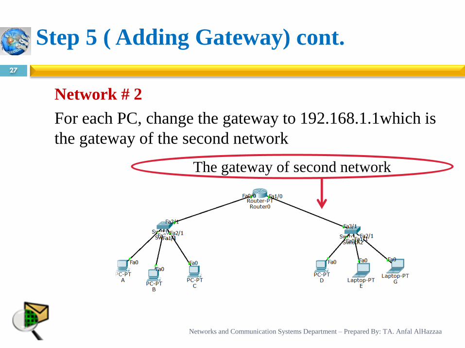
Step 5 ( Adding Gateway) cont.
27
Network # 2
For each PC, change the gateway to 192.168.1.1which is
the gateway of the second network
The gateway of second network
Networks and Communication Systems Department – Prepared By: TA. Anfal AlHazzaa
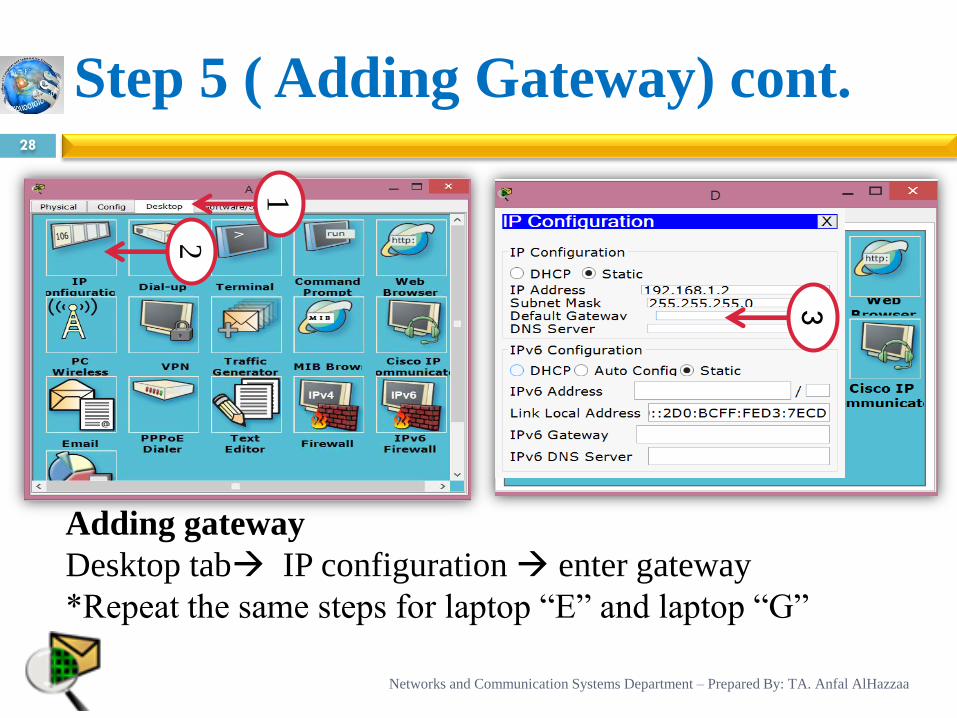
Step 5 ( Adding Gateway) cont. 28
1
3
Adding gateway
Desktop tab IP configuration enter gateway
*Repeat the same steps for laptop “E” and laptop “G”
2
Networks and Communication Systems Department – Prepared By: TA. Anfal AlHazzaa
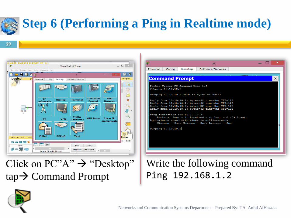
Step 6 (Performing a Ping in Realtime mode)
29
Click on PC”A” “Desktop”
tap Command Prompt
Write the following command Ping 192.168.1.2
Networks and Communication Systems Department – Prepared By: TA. Anfal AlHazzaa
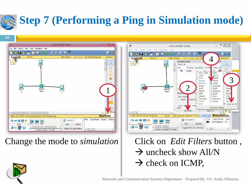
Step 7 (Performing a Ping in Simulation mode)
30
Change the mode to simulation Click on Edit Filters button ,
uncheck show All/N
check on ICMP,
1 2
4
3
Networks and Communication Systems Department – Prepared By: TA. Anfal AlHazzaa
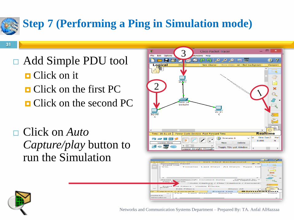
Step 7 (Performing a Ping in Simulation mode)
31
Add Simple PDU tool
Click on it
Click on the first PC
Click on the second PC
Click on Auto Capture/play button to run the Simulation
2
3
Networks and Communication Systems Department – Prepared By: TA. Anfal AlHazzaa
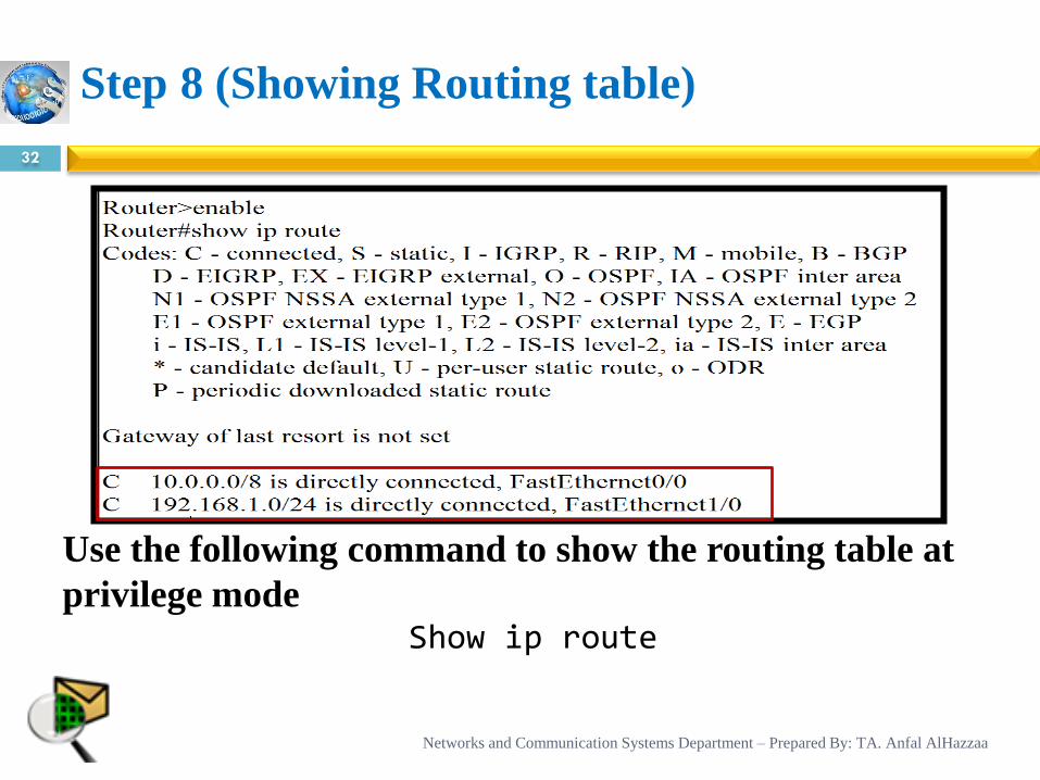
Step 8 (Showing Routing table)
32
Use the following command to show the routing table at
privilege mode Show ip route
Networks and Communication Systems Department – Prepared By: TA. Anfal AlHazzaa
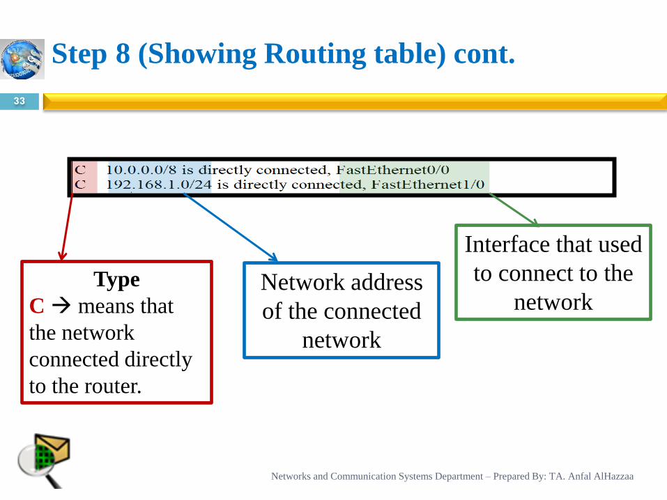
Step 8 (Showing Routing table) cont.
33
Type
C means that
the network
connected directly
to the router.
Network address
of the connected
network
Interface that used
to connect to the
network
Networks and Communication Systems Department – Prepared By: TA. Anfal AlHazzaa
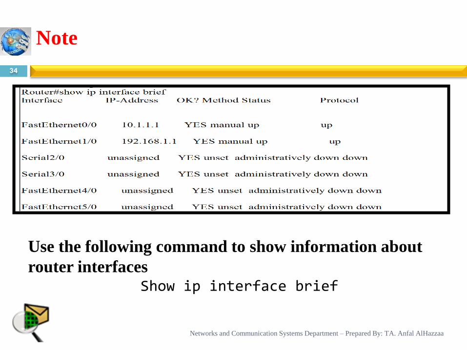
Note
34
Use the following command to show information about
router interfaces Show ip interface brief
Networks and Communication Systems Department – Prepared By: TA. Anfal AlHazzaa
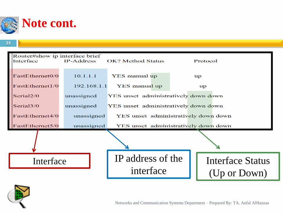
Note cont.
35
Interface
Networks and Communication Systems Department – Prepared By: TA. Anfal AlHazzaa
IP address of the
interface Interface Status
(Up or Down)
References
36
Cisco Packet Tracer Help
IP Routing. (n.d.). Retrieved 2015, from http://orbit-computer-solutions.com/IP-Routing---
Protocols.php#sthash.WWs87CsQ.dpuf
What is Routing table? (n.d.). Retrieved 2015, from http://www.computerhope.com/jargon/r/routing_table.htm
Sheikh Raashid Javid, (2014) Role Of Packet Tracer In Learning Computer Networks.[Online]. Available at:
International Journ al of Advanced Research in Computer and Communication Engineering (Accessed:2015)
Cisco GSS Command Reference (Software Version 2.0) - Global Configuration Mode Commands [Cisco ACE GSS
4400 Series Global Site Selector Appliances]. (2008, April 1). Retrieved 2015, from
http://www.cisco.com/c/en/us/td/docs/app_ntwk_services/data_center_app_services/gss4400series/v2-
0/command/reference/gss_cr/GlblCfg.html
Using the Command-Line Interface. (2008, January 18). Retrieved 2015, from
http://www.cisco.com/c/en/us/td/docs/ios/12_2/configfun/configuration/guide/ffun_c/fcf001.html
What is gateway? - Definition from WhatIs.com. (n.d.). Retrieved 2015, from
http://searchnetworking.techtarget.com/definition/gateway
Cisco command line basics. (2014, May 27). Retrieved 2015, from http://networkkings.org/ccna/1837/
Networks and Communication Systems Department – Prepared By: TA. Anfal AlHazzaa