NeSSI Generation 2: Commercial Applications
21
Siemens Industry, Inc. Copyright 2010; Not to be distributed or published in any form except by Siemens. NeSSI Applications.ppt; CPAC 6 May 2010; Slide 1 NeSSI Generation 2: Commercial Applications Jerry Combs Business Development Manager Siemens Process Analytics
Transcript of NeSSI Generation 2: Commercial Applications

Siemens Industry, Inc.Copyright 2010; Not to be distributed or published in any form
except by Siemens.NeSSI Applications.ppt; CPAC 6 May 2010; Slide 1
NeSSI Generation 2: Commercial Applications
Jerry Combs
Business Development ManagerSiemens Process Analytics

NeSSI Applications.ppt; CPAC 6 May 2010; Slide 2
Siemens Industry, Inc.Copyright 2010; Not to be distributed or published in any form
except by Siemens.
Topics
Description of commercial hardware
Prototype application and explanation of characteristics
Real application with benefits

NeSSI Applications.ppt; CPAC 6 May 2010; Slide 3
Siemens Industry, Inc.Copyright 2010; Not to be distributed or published in any form
except by Siemens.
Siemens Project Description
Objective– Practical smart sampling systems– Suitable for flammable fluids
Parts– Intrinsic Safety Barrier– Cabling system– Intrinsically safe power supply– Intrinsically safe components
System Interconnect– I2C serial cable – made I.S.– No special software in GC– Enable remote and automatic
monitoring
Value and Price– Higher reliability– Easier maintenance– Remote diagnostics
Ethernet Communications Network
“Virtual” SAM in GC
Intrinsically Safe NeSSI Gen. 2 Bus
Sampling System(separate or attached)
Chromatograph
GC Control Electronics
Remote HMI and monitoring

NeSSI Applications.ppt; CPAC 6 May 2010; Slide 4
Siemens Industry, Inc.Copyright 2010; Not to be distributed or published in any form
except by Siemens.
Electrical Concept ImplementationMaxum SSSI Bus
Detector Signal and Control
Multiple channels of Oven Temperature Control
Multiple channels of Electronic Carrier Gas
Pressure Control
Multiple Solenoid Valve Controls
Existing internal serial I/O linking system
Maxum Electronic Section

NeSSI Applications.ppt; CPAC 6 May 2010; Slide 5
Siemens Industry, Inc.Copyright 2010; Not to be distributed or published in any form
except by Siemens.
Maxum GC Electronics
Practical Bus Electrical ImplementationExisting I/O link connected to new module.
• Pepperl-Fuchs Intrinsically Safe Power supply: 9.5v at 1 Amp.
• Powers I/O link and components.• Use additional power supplies as needed
for large numbers of components.
NeSSI Generation 2 Bus;Intrinsically safe;
carries signal and power for devices.
• Existing I/O link used for control of GC Inputs and Outputs.
• Existing protocol supports several hundred I/O channels.
New module with power drivers and Intrinsic Safety Barriers.
V TPA

NeSSI Applications.ppt; CPAC 6 May 2010; Slide 6
Siemens Industry, Inc.Copyright 2010; Not to be distributed or published in any form
except by Siemens.NeSSI Substrates by: Swagelok, Parker or CIRCOR
Electrical Concept ImplementationComponent – Link Responsibility
Maxum GC
Proprietary mechanical NeSSI component by component vendor
Link driver and I.S. barrier by Siemens
Software and link master protocol by Siemens
Proprietary component-specific electronics by component vendor
Chip with I/O link slave software;Intrinsic Safety barriers; and
Standardized interface to component electronics by Siemens
Complete component certification as agreed.

NeSSI Applications.ppt; CPAC 6 May 2010; Slide 7
Siemens Industry, Inc.Copyright 2010; Not to be distributed or published in any form
except by Siemens.
Bus Possibilities
Sampling System
Any suitable bus option could be used: Fieldbus, Profibus, Modbus, CAN Bus, I2C, Ethernet proprietary, other.
SAM
Note:
In Maxum GC, “SAM” is not a separate entity but is virtual.

NeSSI Applications.ppt; CPAC 6 May 2010; Slide 8
Siemens Industry, Inc.Copyright 2010; Not to be distributed or published in any form
except by Siemens.
Component Description
I2C Barrier Module (Siemens)– Provides I.S. protection and buffering for I2C
Multi-variable Sensor (by CIRCOR Tech.)– Flow, up/down stream pressure temperature
Pressure / Temperature Sensor (Swagelok)– Sample pressure and temperature
Pilot Valve Module (Swagelok)– 6 pilot valves for stream select, SSO, ARV
Power Supply (Pepperl & Fuchs)– 7 watts; intrinsically safe– Division 2 power supply optional
ALL COMPONENTS– Make single connection SSSI bus– Intrinsically safe– Rated for cabinet temperatures up to 85°C
I2C Barrier Module I2C I/O Extender
Pressure Sensor Top Hat
Multi-Variable SensorPilot Valve Module
NeSSI Applications.ppt; CPAC 6 May 2010; Slide 9
Siemens Industry, Inc.Copyright 2010; Not to be distributed or published in any form
except by Siemens.
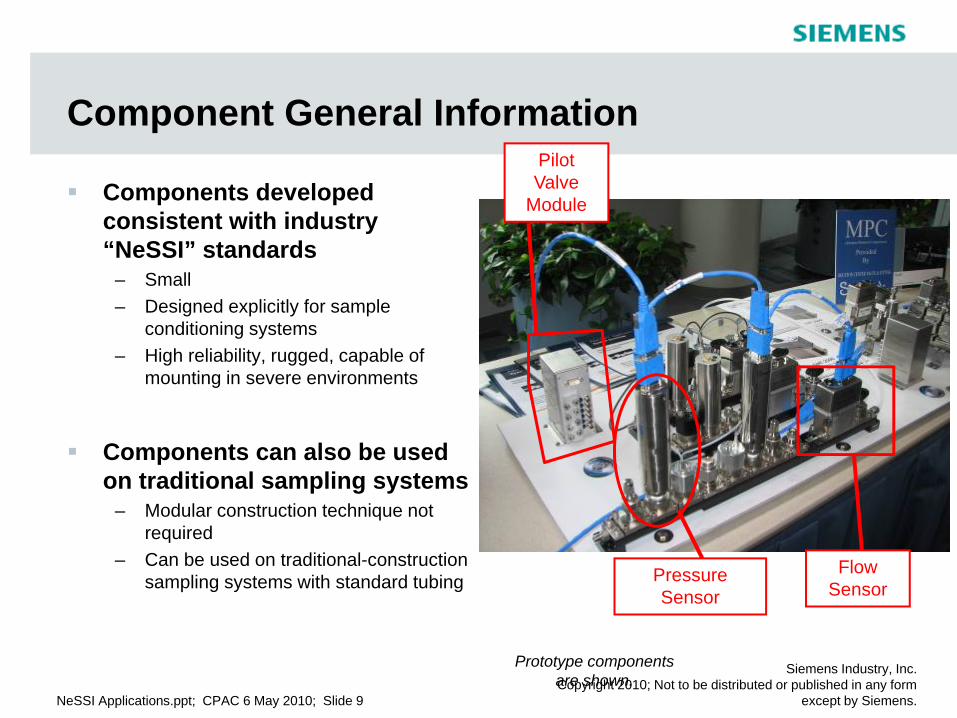
Component General Information
Components developed consistent with industry “NeSSI” standards
– Small– Designed explicitly for sample
conditioning systems– High reliability, rugged, capable of
mounting in severe environments
Components can also be used on traditional sampling systems
– Modular construction technique not required
– Can be used on traditional-construction sampling systems with standard tubing
Prototype components are shown.
Pressure Sensor
Flow Sensor
Pilot Valve
Module

NeSSI Applications.ppt; CPAC 6 May 2010; Slide 10
Siemens Industry, Inc.Copyright 2010; Not to be distributed or published in any form
except by Siemens.
Handling Other Input Signals with Siemens Bus
Siemens SSSI bus includes a “multi-purpose” I/O module
– Multiple analog and digital I/O channels provided
– Connects directly to Siemens SSSI bus– Mounts on DIN rail inside sampling
system– Intrinsically safe module (may require
site approval with any particular connected component)
I/O Extension Module certified and rated for use in hazardous and rugged environments
Module also available for use with MicroSAM to provide external I/O capability
V TPA
TP.S.

NeSSI Applications.ppt; CPAC 6 May 2010; Slide 11
Siemens Industry, Inc.Copyright 2010; Not to be distributed or published in any form
except by Siemens.
Sampling System ExampleTraditional Sampling System (2 vapor process streams + 1 auto-cal stream)
F
AnalyzerSV
SSV
SVCM in GC
Stream 1
Stream 2
Calibration - Validation Standard
Sample Return
ACH
ACH
F
F
Vent / Drain

NeSSI Applications.ppt; CPAC 6 May 2010; Slide 12
Siemens Industry, Inc.Copyright 2010; Not to be distributed or published in any form
except by Siemens.
Sampling System Example (with notes)
Traditional Sampling System (2 vapor process + 1 auto-cal stream)
F
AnalyzerSV
SSV
SVCM in GC
Stream 1
Stream 2
Calibration - Validation Standard
Sample Return
ACH
ACH
Thermostat
Heater
F
F
Insulated, electrically heated cabinet;with window for maintenance
Guard filterARV
Armored rotometers and
flow adjust valves on bypass loops
Main Bypass filters
Regulators and block valves at sample points
Block valves for maintenance on all lines
Constant temperature electric traced tubing
Glass rotometer for analyzer flow
Field connection: AC power, RTD for heat
trace sample lines
SSO
Flow adjust valve for sample loop
Thermometer in cabinet
Double block and vent stream selection valves
Vent / Drain

NeSSI Applications.ppt; CPAC 6 May 2010; Slide 13
Siemens Industry, Inc.Copyright 2010; Not to be distributed or published in any form
except by Siemens.
Sampling System Example (with notes)
Traditional Sampling System (2 vapor process + 1 auto-cal stream)
F
AnalyzerSV
SSV
SVCM in GC
Stream 1
Stream 2
Calibration - Validation Standard
Sample Return
ACH
ACH
Thermostat
Heater
F
F
Insulated, electrically heated cabinet;with window for maintenance
Guard filterARV
Armored rotometers and
flow adjust valves on bypass loops
Main Bypass filters
Regulators and block valves at sample points
Block valves for maintenance on all lines
Constant temperature electric traced tubing
Glass rotometer for analyzer flow
Field connection: AC power, RTD for heat
trace sample lines
SSO
Flow adjust valve for sample loop
Thermometer in cabinet
Double block and vent stream selection valves
Vent / Drain

NeSSI Applications.ppt; CPAC 6 May 2010; Slide 14
Siemens Industry, Inc.Copyright 2010; Not to be distributed or published in any form
except by Siemens.
Smart Sampling System ExampleSmart System With Siemens Sensors and SSSI Bus
F
Analyzer
SSV
Stream 1
Stream 2
Sample Return
ACH
ACH
F
F
Insulated, electrically heated cabinet
Multi-Variable Sensors
Pilot Valve
Module
PFPT
PFPT
PFPT
Air
Pressure-Temperature Sensor
PT
Calibration - Validation Standard
SSSI Bus
Vent / Drain
SVBus P.S.
NeSSI Applications.ppt; CPAC 6 May 2010; Slide 15
Siemens Industry, Inc.Copyright 2010; Not to be distributed or published in any form
except by Siemens.
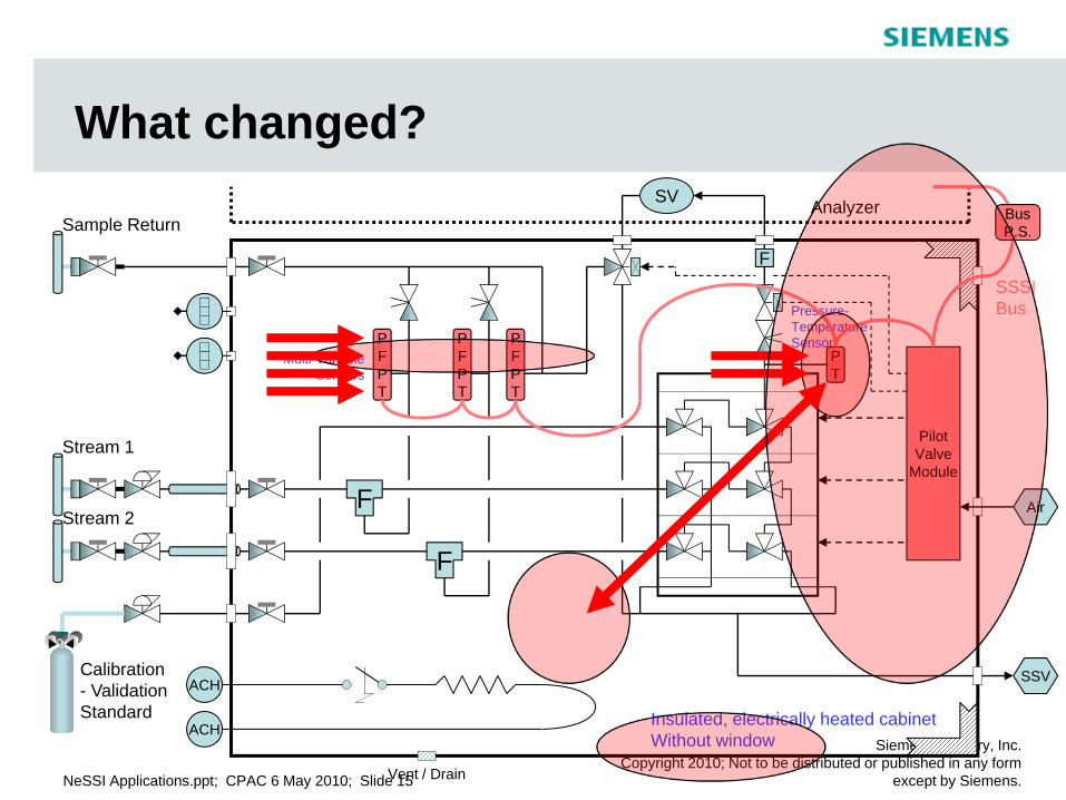
What changed?
F
Analyzer
SSV
Stream 1
Stream 2
Sample Return
ACH
ACH
F
F
Insulated, electrically heated cabinetWithout window
Multi-Variable Sensors
Pilot Valve
Module
PFPT
PFPT
PFPT
Air
Pressure-Temperature Sensor
PT
Calibration - Validation Standard
SSSI Bus
Vent / Drain
SVBus P.S.

NeSSI Applications.ppt; CPAC 6 May 2010; Slide 16
Siemens Industry, Inc.Copyright 2010; Not to be distributed or published in any form
except by Siemens.
What’s Going On…?
Rotometers eliminated; replaced with Flow-Pressure-Temperature Sensors
Thermometer eliminated; replaced with Temperature Sensor
Pressure Sensors added to standard bottle inlet and inlet to analyzer
SVCM in analyzer eliminated; replaced with Pilot Valve Module
Cabinet window eliminated; all sensors can be read from outside and remote
All new Sensors and Pilot Valve Module connected to analyzer by single I.S. bus cable
Any blockage of bypass loops diagnosed by in-line flow and pressure sense
Heat tracing and speed loop temperature diagnosed by in-line temperature sense on each process gas
Main stream filters diagnosed by differential pressure across filter to selected stream
Blockage of analyzer loop in SV or other valves diagnosed by in-line sample flow and inlet and outlet pressures
Fluctuations of return point pressure diagnosed by in-line Pressure Sensor
Calibration-Validation bottle checked by inline pressure sensor
SSO, ARV and Stream Select valves switched inside cabinet
Cabinet heater diagnosed by Temperature Sensor
What changed? How does it work?

NeSSI Applications.ppt; CPAC 6 May 2010; Slide 17
Siemens Industry, Inc.Copyright 2010; Not to be distributed or published in any form
except by Siemens.
Air Monitor: Practical Installation
• Analysis of atmosphere for VCM• Parallel analysis of 2 points at once• 15 process streams per GC• Plus 1 to 3 calibration / validation inputs• Need to validate flowing sample into GC
sample loop
• ISSUE: Extensive and expensive field installation for controls and sensors
F
Typical: 15 pneumatic controls
F
Pneumatic operators internal
Typical: 15 sample points plus1 to 3 reference points
2 flow sense measurements
related to 2 parallel sampling paths
Large cabinet enclosure; 2 doors, single interior zone

NeSSI Applications.ppt; CPAC 6 May 2010; Slide 18
Siemens Industry, Inc.Copyright 2010; Not to be distributed or published in any form
except by Siemens.
Extended System Signal cable to GC
F
F

NeSSI Applications.ppt; CPAC 6 May 2010; Slide 19
Siemens Industry, Inc.Copyright 2010; Not to be distributed or published in any form
except by Siemens.
Typical: 15 sample points plus 1 to 3 reference points
Air Monitor: Improved with NeSSI
F
F
VCM
Swagelok valve control modules3 each; 6 pilots per module
Circor DMT flow-pressure-temperature sensor
2 each; 1 per concurrent sample loop
P&F I.S. Power Supply
Single I.S. cable for all interconnects to GC
VCMVCM
Large cabinet enclosure; 2 doors, single interior zone

NeSSI Applications.ppt; CPAC 6 May 2010; Slide 20
Siemens Industry, Inc.Copyright 2010; Not to be distributed or published in any form
except by Siemens.
Why? Benefits To the UserSystem Enables Remote, Automated Monitoring of Key Operating Parameters
Personnel safety – All flow and pressure sensors are high-pressure safe and suitable for toxic samples– Mechanical security; cabinet simplified by elimination of window– Lock-out practical because maintenance inspection does not require internal access
Reduced installation and engineering cost– Stream select tubing to SVCM in GC is eliminated– Any analog electrical connections to GC are eliminated
Improved measurement validity and reliability– Continuous monitoring of system automatically versus periodic spot check by human walk-by– Validity assured during upsets, bad weather or storm conditions, holidays and other times of
lowered maintenance– Continuous data validation possible on critical or quality-mandated measurements
Maintenance cost reduction– Elimination of periodic human walk-by inspection– Capability for preventative and predictive maintenance
– Example: decreasing flow measurement can indicate filter degradation where as simple flow loss alarms occur only when failure has already occurred
– When maintenance is required, personnel know maintenance situation, parts and tools required before going out to system

NeSSI Applications.ppt; CPAC 6 May 2010; Slide 21
Siemens Industry, Inc.Copyright 2010; Not to be distributed or published in any form
except by Siemens.
Discussion and Questions