NERC Reliability Initiatives and Smart Grid · PDF fileNERC Reliability Initiatives and Smart...
35
NERC Reliability Initiatives and NERC Reliability Initiatives and Smart Grid Smart Grid IEEE PES Late Breaking News July 28, 2009 Robert W. Cummings Director of Event Analysis & Information Exchange
Transcript of NERC Reliability Initiatives and Smart Grid · PDF fileNERC Reliability Initiatives and Smart...

NERC Reliability Initiatives andNERC Reliability Initiatives andSmart Grid Smart Grid
IEEE PESLate Breaking News July 28, 2009
Robert W. CummingsDirector of Event Analysis & Information Exchange

System Protection and Control Performance Improvement Initiative

Protection & Controls Initiative
Announced at February Board meeting
Letter to industry to come out shortly
NERC Board recognition of the importance of system protection to reliability
Goal: Improve BES reliability
Purpose: Improve the performance of power system Protection Systems through fostering technical excellence in protection and control system design, coordination, and practices.

Protection & Controls Initiative
Elevate System Protection and ControlTask Force to Subcommittee status• Increased emphasis on the importance of protection
Collaborative efforts with:• IEEE Power & Energy Society• IEEE Power System Relay Committee• Bridge between IEEE standards and NERC system
performance requirements (in NERC standards)
Coordinate Protection Standards Philosophies and Standards Work• Reduce discrepancies• Technical basis for all protection standards changes

Initial Targeted Areas
PRC Standards Technical Support• SPCS to provide technical SME support to Standards process
Relay Loadability• Standard PRC-023 – Relay Loadability passed by NERC Board,
awaiting FERC approval
Protection System Reliability (redundancy)• SPCS Technical Reference Document & SAR
Posted for comments 1/20 – 2/18
Generator Frequency and Voltage Protective Relay Coordination • Standards Project 2007-09 – Generator Verification
• Drafting of Standard PRC-024-1 — Generator Frequency and Voltage Protective Relay Settings

Initial Targeted Areas
Transmission and Generation Protection System Misoperations• Technical review of PRC-004 -- Analysis and Mitigation of
Transmission and Generation Protection System Misoperations
• Includes NERC-wide definition of protection misoperations for NERC reporting and system performance metrics
Protection System Maintenance• SPCTF 2007 Technical Reference Standards on Protection System
maintenance
• Project 2007-17 – Transmission and Generation Protection System Maintenance and Testing, PRC-005 in re-drafting phase

Initial Targeted Areas
Protection System Coordination• Transmission Protection Coordination
Support for revisions to PRC-001
• Trans & Gen Protection Coordination – IEEE collaboration
SPCS Technical Reference – Power Plant and Transmission System Protection Coordination – support for revisions to PRC-001
BES System Performance & Protection Coordination with Generator Controls• Improved modeling of governors and other generator controls
• New control models need to be applied
• Model validation to actual system performance essential

Initial Targeted Areas
BES System Performance & Protection Coordination with Turbine/Boiler Controls• Response to leading trend in system disturbances
• Largely uncharted area for modeling by planners
• Discussions with industry experts and turbine control manufacturers on appropriate level of modeling (detailed modeling not appropriate)
System ModelingImprovement Initiative
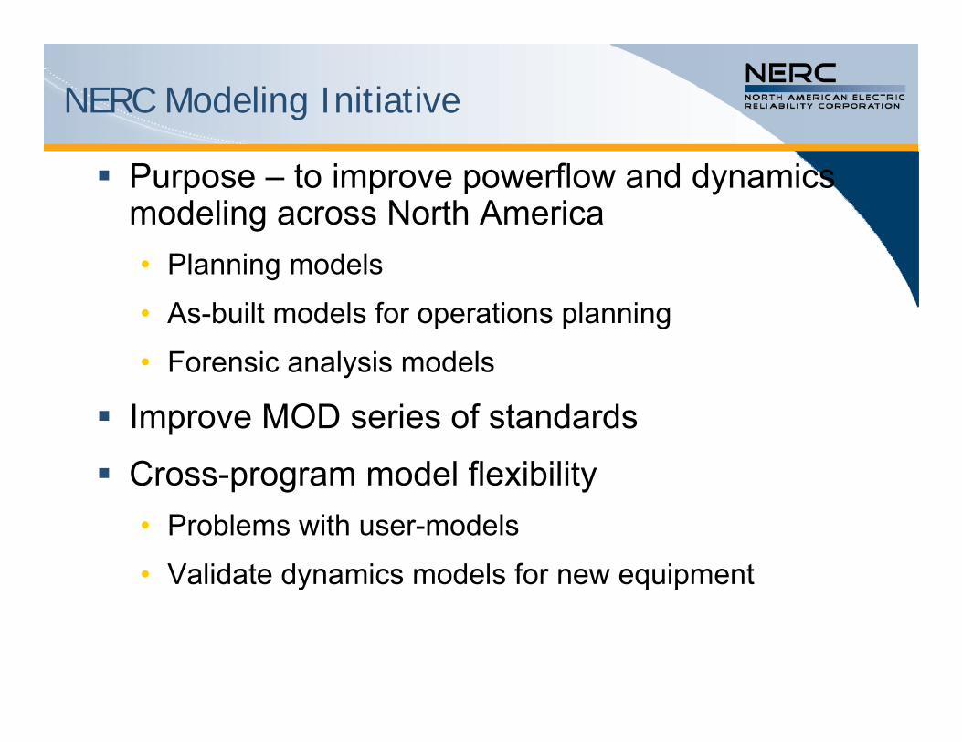
NERC Modeling Initiative
Purpose – to improve powerflow and dynamics modeling across North America• Planning models
• As-built models for operations planning
• Forensic analysis models
Improve MOD series of standards
Cross-program model flexibility• Problems with user-models
• Validate dynamics models for new equipment

Basis in Blackout Recommendations
Improve quality of system modeling data and data exchange practices• NERC Recommendation 14
• US-Canada TF Recommendation 24
Generation and Transmission Performance Report Recommendations• Background of original recommendations
• Strengthened recommendations

TR-4 – Powerflow Modeling
A. Modeling Groups should reinvestigate feasibility of a CIM capable powerflow creation database
B. NERC should create initiative to improve overall powerflow modeling techniques
C. Powerflow cases should be periodically benchmarked to actual system conditions at various load levels
D. All generators should be periodically tested to ensure that their claimed MW and Mvar ratings are accurate and realizable● Testing should also be done to confirm the performance of
generator dynamic controls and that their respective models in the System Dynamics Databases are accurate.

TR-12– Improve & Validate Dynamic Models
A. Create a feedback loop in modeling process – CIM compatible
B. Initiate dynamic model validation in EI for generators and dynamic responsive equipment
C. Codify (with IEEE) new standard for powerflow and dynamics data formats
D. Provide forum for ongoing development, testing, and validation of new and improved dynamic models
E. Improve load modeling for more accurate powerflow and dynamics analysis
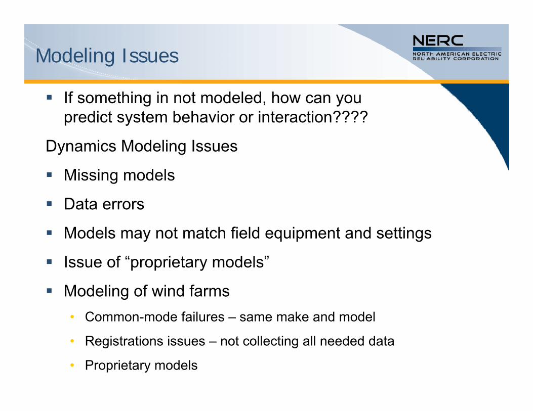
Modeling Issues
If something in not modeled, how can you predict system behavior or interaction????
Dynamics Modeling Issues
Missing models
Data errors
Models may not match field equipment and settings
Issue of “proprietary models”
Modeling of wind farms• Common-mode failures – same make and model
• Registrations issues – not collecting all needed data
• Proprietary models

Need for New Modeling
Turbine / boiler control models needed• Units may remain stable, but ramp to zero and trip
Far more complex dynamic load models needed to analyze and predict FIDVR (Fault-Induced Delayed Voltage Recovery) behavior• More load composition data needed to do this
Better governor models
Better SPS/RAS models
Models for new power electronic devices

Intelligent Integration of Electronically-Coupled Resources and Demand

Smart Grids – a Reliability Perspective
Defined from a Reliability Perspective
Two-way flow of energy and communications enabling new technologies to supply, deliver and consume electricity.
Functions • Enhanced flexibility and control
• Balancing variable demand & resources
• Demand Response
• Large deployment of sensor & automation technologies
• etc.

Smart Grid Integration
Reliability Considerations to Plan a System that Operators can Reliably Operate• Design Large-Scale, Non-Linear Control (new tools?)• Large & Small Signal Stability maintained (new tools?)• Coordination of controls (centralized/decentralized)• Device interconnection standards dependent on
function• System sensitivity analyses must be expanded • Cyber security considerations in planning, design and
operations• Operations will change (new tools?)

Renewables and Smart Grid
Intelligently integrate renewable resources
Intelligent integration of smart gridtechnologies to take advantage of tremendous potentials while maintaining reliability
Overall Reliability Concerns
System inertia – maintaining system stability
Ability to maintain voltage and frequency control
Interactions of myriad of control systems
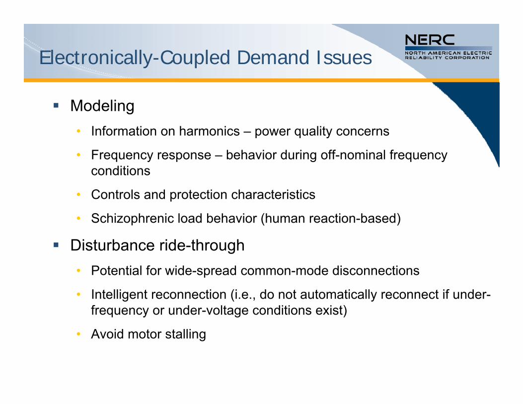
Electronically-Coupled Demand Issues
Modeling• Information on harmonics – power quality concerns
• Frequency response – behavior during off-nominal frequency conditions
• Controls and protection characteristics
• Schizophrenic load behavior (human reaction-based)
Disturbance ride-through• Potential for wide-spread common-mode disconnections
• Intelligent reconnection (i.e., do not automatically reconnect if under-frequency or under-voltage conditions exist)
• Avoid motor stalling

Electronically-Coupled Resource Issues
Disturbance ride-through• Stay connected through off-nominal frequency
(over- and under-frequency) events, including coordination with utilities’ Under-Frequency Load Shedding programs
• Stay connected through off-nominal voltage events, including coordination with utilities’ Under-Voltage Load Shedding program
• Potential common-mode failures
• Intelligent reconnection (i.e., do not automatically restart/reconnect if over-frequency or over-voltage conditions exist)

Electronically-Coupled Resource Issues
Voltage Stability• Provide primary voltage control for transient stability
• Provide secondary voltage control for post-transient stability
• Carry (or have a linkage to) reactive reserves
Be capable of a two-quadrant operation, delivering leading and lagging power factor through the entire power output range

Electronically-Coupled Resource Issues
Frequency Control • Primary frequency control for arresting system frequency
deviations
• Secondary frequency control, participation in AGC
• Ability to dispatch and follow power schedule
• Ability to carry Frequency Responsive Reserves
Oscillation Damping
Contribute to positive damping of power oscillatory modes

Electronically-Coupled Resource Issues
Additional requirements• Make generic powerflow and dynamic models, and
associated data sets available for power system studies prior to interconnection. These must be validated by measured performance in operation
• Provide self-protection and control parameters for power system studies – necessary for evaluation of potential common-mode failures based on controls or performance parameters
• Disturbance data recorders – 30+ samples per second, time synchronized – needed to validate performance and models
• Participate in monitoring systems, remedial action schemes, and other reliability schemes as identified in regional planning process

Smart Grid Integration Task Force
NERC Staff Proposal:
Task Force formed to evaluate reliability considerations to integrate Smart Grids in Planning, Design and Operations• Coordinated Effort between PC/OC/CIP, lead by PC
• Evaluate Changes in Planning, Design & Operations
• Make Recommendations for next steps
Complete Report by December 2009

Frequency Response Initiative

Frequency Response, termed beta (β), is• a fundamental reliability service• a combination of governor and load response• Inversely related to frequency excursions
Frequency Response is declining• Should be increasing with load & generation growth• Part of the decrease may be better measurement
Performance-based standards quite possibly on the horizon (FERC Order No. 693)
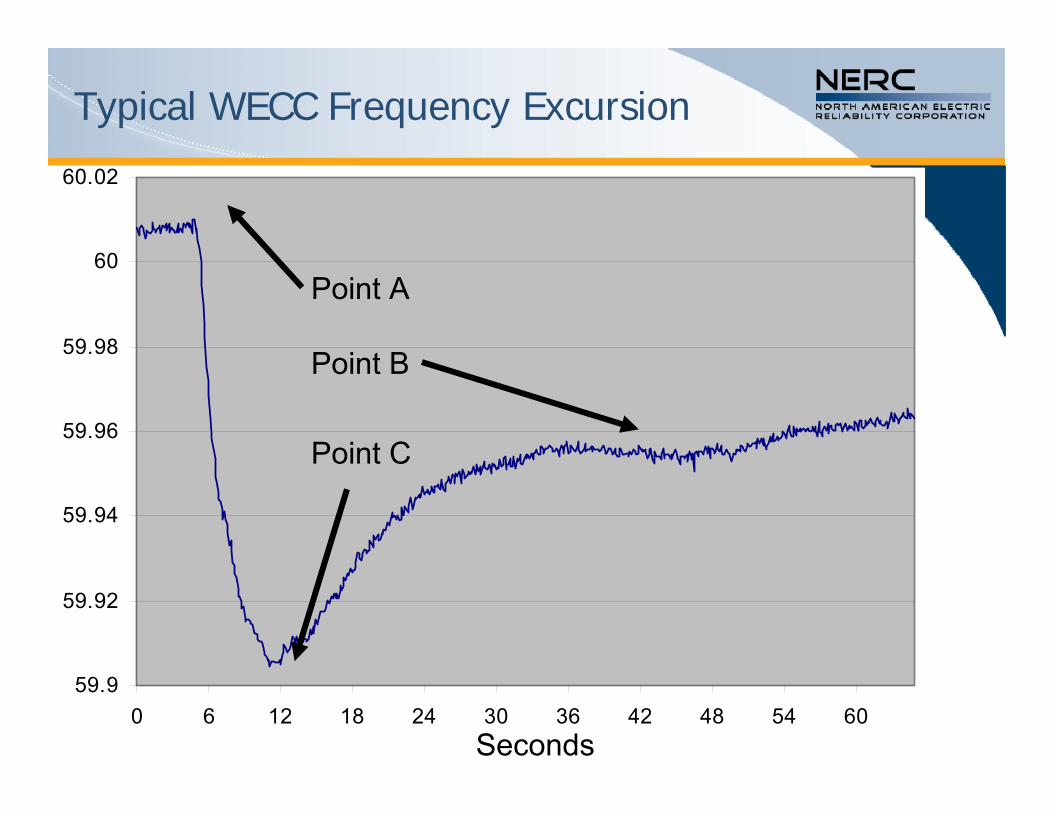
Frequency Response Basics
59.9
59.92
59.94
59.96
59.98
60
60.02
0 6 12 18 24 30 36 42 48 54 60Seconds
Point C
Point A
Point B
Typical WECC Frequency Excursion

59.8
59.85
59.9
59.95
60
0 6 12 18 24 30 36 42 48 54 60Seconds
Point A
Point B
βInt= Δ MW/(10* Δf)
βBA = Δ NiA/(10* Δf)
βGen = Δ MW/(10* Δf)
Typical ERCOT Frequency Excursion
59.94
59.95
59.96
59.97
59.98
59.99
60
60.01
60.02
0 6 12 18 24 30 36 42 48 54 60Seconds
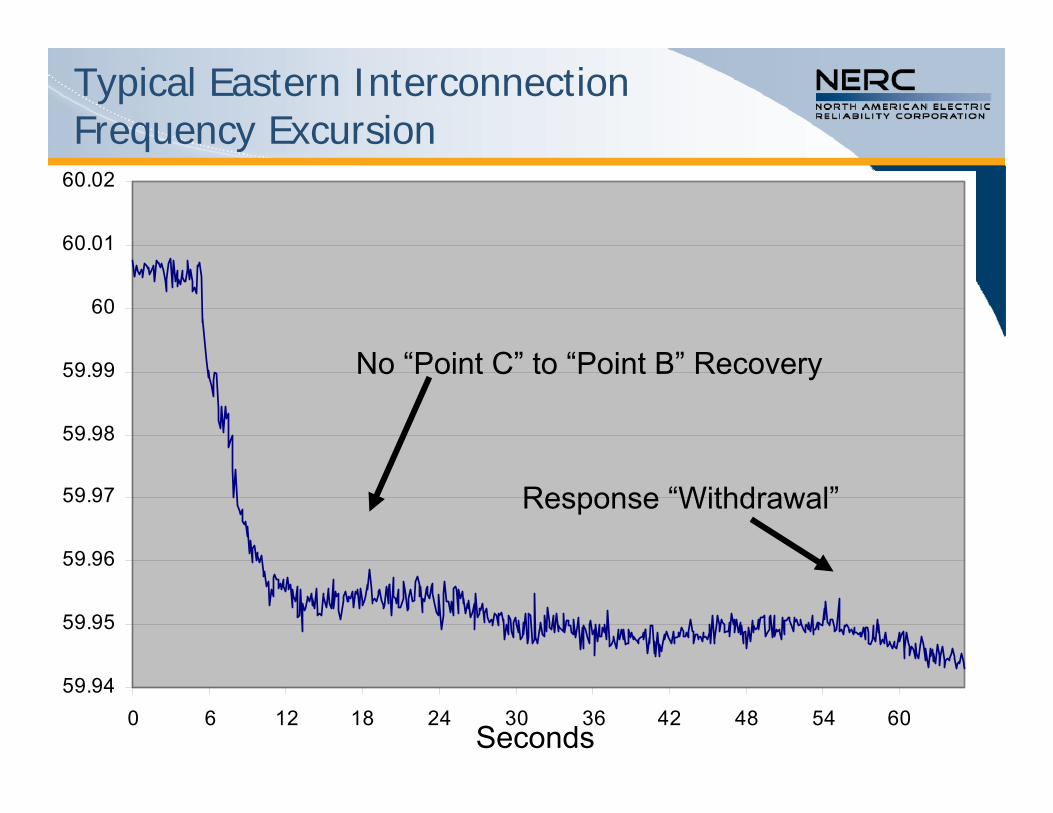
No “Point C” to “Point B” Recovery
Response “Withdrawal”
Typical Eastern Interconnection Frequency Excursion

* Ingleson and Nagle StudyDecline of 72MW/0.1Hz/year
Eastern Interconnection Frequency Response Trend

Easter Interconnection Beta
2500
2600
2700
2800
2900
3000
3100
3200
3300
3400
3500
2000 2001 2002 2003 2004 2005 2006
MW
/0.1
Hz
Mean Median
* Ingleson and Ellis/NERC Resources Subcommittee/Virginia Tech2007-2008 Response = -2550MW/0.1Hz
*
Recent Frequency Response

Small Excursions (>28mHz)
Follows a seasonal pattern, # are increasing
28mHz represented loss of about 1000MW in 1994
Change believed to be primarily due to decline in frequency response (70 MW per 0.1Hz /year since ‘94)
Pumped storage and interchange schedule changes now causing excursions of this size
Small excursions are a symptom, not necessarily a problem themselves
Patterns give a clue to sampling techniques needed to objectively calculate Balancing Authority and Generator Frequency Response

Frequency Response Initiative
Employ Frequency Monitoring and Analysis tool to look at all FTL excursions• Sample events being used for shakedown
NERC Advisory Alert to be issued on maintaining better frequency response
One target – to improve modeling of actual response in studies
Stay Tuned…still being developed!

Questions?