Nepal GEA SOA ESB Design Guidelines
50
Nepal GEA SOA ESB Design Guidelines
Transcript of Nepal GEA SOA ESB Design Guidelines

Nepal GEA SOA ESB Design Guidelines
Nepal GEA SOA ESB Design Guidelines
Page 2
Table of Contents
1. Executive Summary ................................................................................................................................................ 5
1.1 Purpose .................................................................................................................................................................... 5
1.2 Scope ........................................................................................................................................................................ 5
1.3 Definitions ............................................................................................................................................................... 5
1.4 References ................................................................................................................................................................ 7
2. Design Guidelines ................................................................................................................................................... 9
2.1 SOA implementation on Enterprise Service Bus ................................................................................................... 9
2.2 Service Delivery Gateway Architecture ................................................................................................................. 11
2.2.1 Objectives ............................................................................................................................................... 11
2.2.2 Artefacts .................................................................................................................................................. 12
2.2.2.1 Model ................................................................................................................................................. 12
2.2.2.2 Service ............................................................................................................................................... 12
2.2.2.3 Transports ......................................................................................................................................... 12
2.2.2.4 Routers .............................................................................................................................................. 13
2.2.2.5 Components ...................................................................................................................................... 14
2.2.3 Deployment View ................................................................................................................................... 15
2.2.3.1 Topology ............................................................................................................................................ 15
2.2.3.2 High Availability ............................................................................................................................... 16
2.2.3.3 Fault Tolerance ................................................................................................................................. 17
2.2.3.4 Exception Monitor ............................................................................................................................ 17
2.2.3.5 Security Framework ......................................................................................................................... 19
2.2.3.6 Galaxy ............................................................................................................................................... 20
2.3 Service Design Principles ....................................................................................................................................... 21
2.3.1 Standardized Service Contract .............................................................................................................. 21
2.3.2 Service Loose Coupling .......................................................................................................................... 21
2.3.2.1 Contract to Functional Coupling ..................................................................................................... 21
2.3.2.2 Contract to Implementation Coupling ........................................................................................... 22
2.3.2.3 Contract to Logic Coupling ............................................................................................................. 22
2.3.2.4 Contract to Technology Coupling ................................................................................................... 22
2.3.2.5 Logic to Contract Coupling ............................................................................................................. 22
2.3.3 Service Abstraction ............................................................................................................................... 22
2.3.4 Service Reusability ................................................................................................................................ 22
2.3.5 Service Autonomy ................................................................................................................................. 22
Nepal GEA SOA ESB Design Guidelines
Page 3
2.3.6 Service Statelessness ............................................................................................................................. 23
2.3.7 Service Discoverability .......................................................................................................................... 23
2.3.8 Service Compos ability .......................................................................................................................... 23
2.4 Service Design Patterns ........................................................................................................................................ 24
2.4.1 Service Inventory Design Patterns ....................................................................................................... 24
2.4.1.1 Foundational Inventory Patterns.................................................................................................... 24
2.4.1.2 Logical Inventory Layer Patterns .................................................................................................... 26
2.4.1.3 Inventory Implementation Patterns ............................................................................................... 27
2.4.2 Service Design Patterns ........................................................................................................................ 28
2.4.2.1 Foundational Service Patterns ........................................................................................................ 29
2.4.2.2 Service Implementation Patterns ................................................................................................... 30
2.4.2.3 Service Security Patterns ................................................................................................................. 32
2.4.2.4 Legacy Encapsulation Patterns ....................................................................................................... 33
2.4.2.5 Service Governance Patterns .......................................................................................................... 35
2.4.3 Service Composition Design Patterns .................................................................................................. 36
2.4.3.1 Service Messaging Patterns ............................................................................................................. 37
2.4.3.2 Transformation Patterns ................................................................................................................. 38
2.5 Guidelines on Enabling Services for Applications .............................................................................................. 40
2.5.1 Prerequisites .......................................................................................................................................... 40
2.5.2 Web Based J2EE applications .............................................................................................................. 40
2.5.3 Web based Microsoft DOT NET ............................................................................................................ 41
2.5.4 PHP Applications .................................................................................................................................. 42
2.5.5 Two Tier Architectures with MS Access backend ................................................................................ 43
2.5.6 Indicative Mule Configuration ............................................................................................................. 43
2.6 Guidelines on Service Contracts between Consumers and Producers ............................................................... 44
2.6.1 Decoupled Contract .............................................................................................................................. 44
2.6.2 Contract De-normalization ................................................................................................................... 45
2.6.3 Concurrent Contracts ............................................................................................................................ 46
2.6.4 Validation Abstraction .......................................................................................................................... 48
2.7 Security Framework on Service Invocations ....................................................................................................... 49
2.7.1 Data Confidentiality .............................................................................................................................. 49
2.7.2 Data Origin Authentication .................................................................................................................. 49
2.7.3 Direct Authentication ........................................................................................................................... 49
2.7.4 Brokered Authentication ...................................................................................................................... 50

Nepal GEA SOA ESB Design Guidelines
Page 4
1. Executive Summary
Nepal GEA SOA ESB Design Guidelines
Page 5
1. Executive Summary
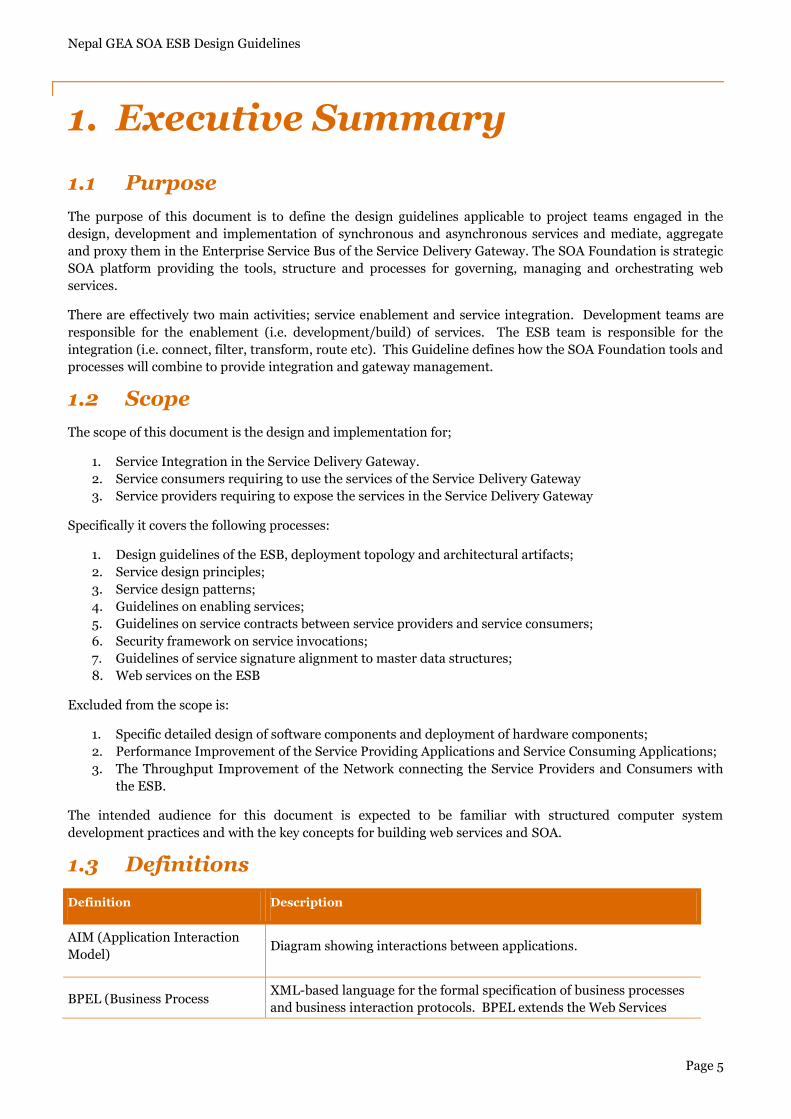
1.1 Purpose
The purpose of this document is to define the design guidelines applicable to project teams engaged in the
design, development and implementation of synchronous and asynchronous services and mediate, aggregate
and proxy them in the Enterprise Service Bus of the Service Delivery Gateway. The SOA Foundation is strategic
SOA platform providing the tools, structure and processes for governing, managing and orchestrating web
services.
There are effectively two main activities; service enablement and service integration. Development teams are
responsible for the enablement (i.e. development/build) of services. The ESB team is responsible for the
integration (i.e. connect, filter, transform, route etc). This Guideline defines how the SOA Foundation tools and
processes will combine to provide integration and gateway management.
1.2 Scope
The scope of this document is the design and implementation for;
1. Service Integration in the Service Delivery Gateway.
2. Service consumers requiring to use the services of the Service Delivery Gateway
3. Service providers requiring to expose the services in the Service Delivery Gateway
Specifically it covers the following processes:
1. Design guidelines of the ESB, deployment topology and architectural artifacts;
2. Service design principles;
3. Service design patterns;
4. Guidelines on enabling services;
5. Guidelines on service contracts between service providers and service consumers;
6. Security framework on service invocations;
7. Guidelines of service signature alignment to master data structures;
8. Web services on the ESB
Excluded from the scope is:
1. Specific detailed design of software components and deployment of hardware components;
2. Performance Improvement of the Service Providing Applications and Service Consuming Applications;
3. The Throughput Improvement of the Network connecting the Service Providers and Consumers with
the ESB.
The intended audience for this document is expected to be familiar with structured computer system
development practices and with the key concepts for building web services and SOA.
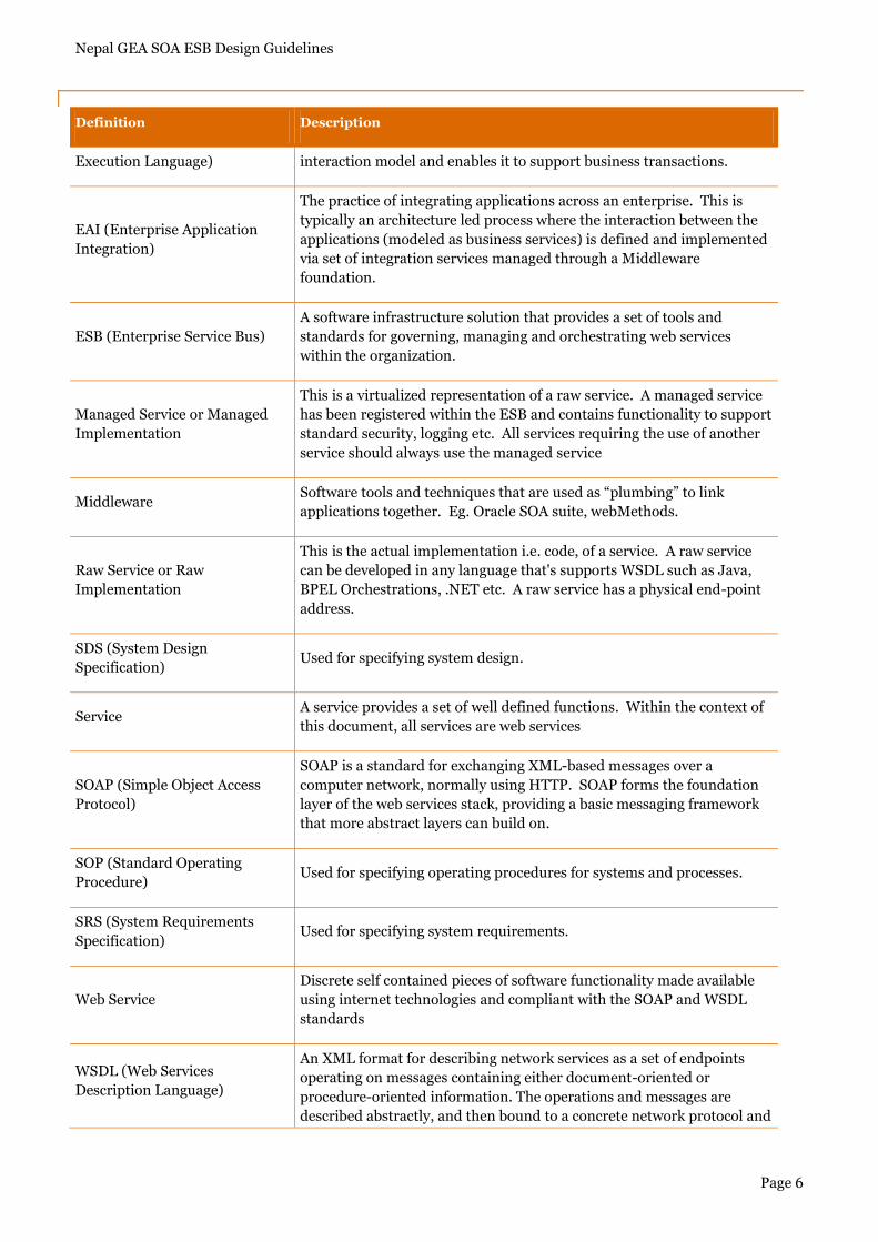
1.3 Definitions
Definition Description
AIM (Application Interaction
Model) Diagram showing interactions between applications.
BPEL (Business Process XML-based language for the formal specification of business processes
and business interaction protocols. BPEL extends the Web Services
Nepal GEA SOA ESB Design Guidelines
Page 6
Definition Description
Execution Language) interaction model and enables it to support business transactions.
EAI (Enterprise Application
Integration)
The practice of integrating applications across an enterprise. This is
typically an architecture led process where the interaction between the
applications (modeled as business services) is defined and implemented
via set of integration services managed through a Middleware
foundation.
ESB (Enterprise Service Bus)
A software infrastructure solution that provides a set of tools and
standards for governing, managing and orchestrating web services
within the organization.
Managed Service or Managed
Implementation
This is a virtualized representation of a raw service. A managed service
has been registered within the ESB and contains functionality to support
standard security, logging etc. All services requiring the use of another
service should always use the managed service
Middleware Software tools and techniques that are used as “plumbing” to link
applications together. Eg. Oracle SOA suite, webMethods.
Raw Service or Raw
Implementation
This is the actual implementation i.e. code, of a service. A raw service
can be developed in any language that's supports WSDL such as Java,
BPEL Orchestrations, .NET etc. A raw service has a physical end-point
address.
SDS (System Design
Specification) Used for specifying system design.
Service A service provides a set of well defined functions. Within the context of
this document, all services are web services
SOAP (Simple Object Access
Protocol)
SOAP is a standard for exchanging XML-based messages over a
computer network, normally using HTTP. SOAP forms the foundation
layer of the web services stack, providing a basic messaging framework
that more abstract layers can build on.
SOP (Standard Operating
Procedure) Used for specifying operating procedures for systems and processes.
SRS (System Requirements
Specification) Used for specifying system requirements.
Web Service
Discrete self contained pieces of software functionality made available
using internet technologies and compliant with the SOAP and WSDL
standards
WSDL (Web Services
Description Language)
An XML format for describing network services as a set of endpoints
operating on messages containing either document-oriented or
procedure-oriented information. The operations and messages are
described abstractly, and then bound to a concrete network protocol and
Nepal GEA SOA ESB Design Guidelines
Page 7
Definition Description
message format to define an endpoint.
1.4 References
The following documents are referenced within this specification:
Building Web Services with Java, Second Edition, by Steve Graham et al
The Definitive Guide to SOA with BEA Aqualogic Service Bus by Jeff Davies
SOA Governance by Todd Biske
Web Service Contract Design and Versioning for SOA by Thomas Erl et al
SOA Design Patterns by Thomas Erl
Java Web Services Up and Running by Martin Kalin
Enterprise Integration Patterns by Gregory Hohpe and Bobby Woolf
Mule in Action by David Dossot and John D‟Emic

Nepal GEA SOA ESB Design Guidelines
Page 8
2. Design Guidelines
Nepal GEA SOA ESB Design Guidelines
Page 9
2. Design Guidelines
2.1 SOA implementation on Enterprise Service Bus
Application integration encompasses all the difficulties that heterogeneity creates in the world of software,
leading to diversity in all the aspects of system communications and interrelations:
Transport - applications can accept input from a variety of means, from the file system to the network.
Data format - speaking the right protocol is only part of the solution, as applications can use almost any
form of representation for the data they exchange.
Invocation styles - synchronous, asynchronous, or batch call semantics entail very different integration
strategies.
Lifecycles - applications of different origins that serve varied purposes tend to have disparate
development, maintenance, and operational lifecycles.
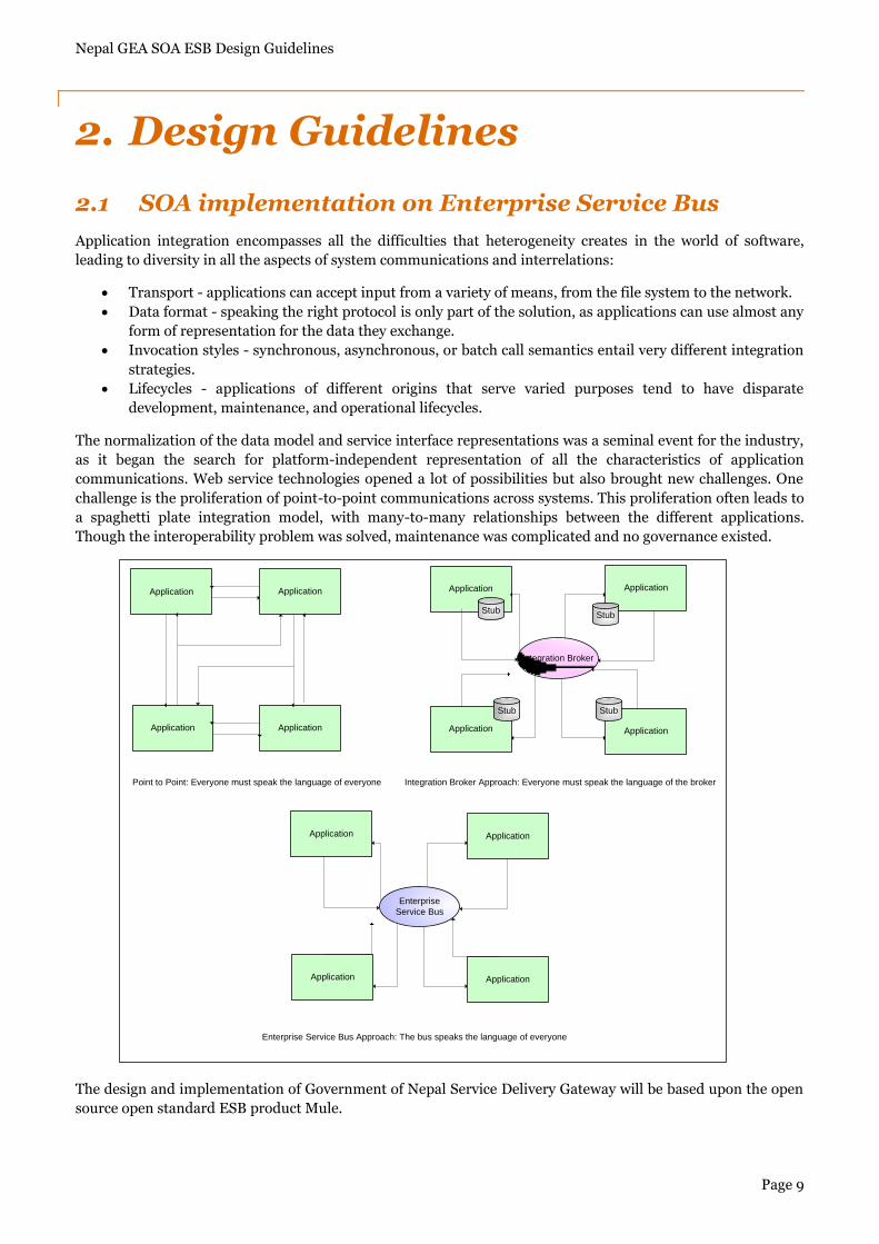
The normalization of the data model and service interface representations was a seminal event for the industry,
as it began the search for platform-independent representation of all the characteristics of application
communications. Web service technologies opened a lot of possibilities but also brought new challenges. One
challenge is the proliferation of point-to-point communications across systems. This proliferation often leads to
a spaghetti plate integration model, with many-to-many relationships between the different applications.
Though the interoperability problem was solved, maintenance was complicated and no governance existed.
The design and implementation of Government of Nepal Service Delivery Gateway will be based upon the open
source open standard ESB product Mule.
Application Application
Application Application
Application Application
Application Application
Integration Broker
Application Application
Application Application
Enterprise
Service Bus
Stub
Stub Stub
Stub
Point to Point: Everyone must speak the language of everyone Integration Broker Approach: Everyone must speak the language of the broker
Enterprise Service Bus Approach: The bus speaks the language of everyone
Nepal GEA SOA ESB Design Guidelines
Page 10
The Enterprise Service Bus would foster better practices by encouraging loosely coupled integration and at the
same time discouraging many-to-many connectivity. Moreover, this platform wouldn‟t require any change from
existing applications. It would be able to speak all languages and make dissembling systems talk with each
other through its capacity to translate from one form of communication to another.
Acting like the bus at the core of computer architecture, this middleware would become the backbone of
enterprise messaging, if not, according to some, the pillar of the service-oriented architecture (SOA) redesign
that enterprises were going through. On top of solving the aforementioned integration issues, this bus would
offer extra value-added services, like intelligent routing of messages between systems, centralized security
enforcement, or quality of service measurement, as mentioned below:
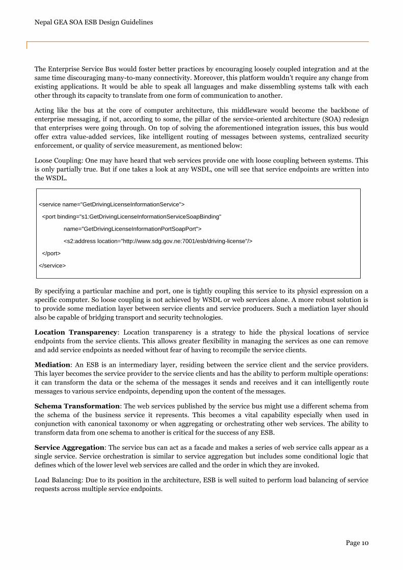
Loose Coupling: One may have heard that web services provide one with loose coupling between systems. This
is only partially true. But if one takes a look at any WSDL, one will see that service endpoints are written into
the WSDL.
By specifying a particular machine and port, one is tightly coupling this service to its physicl expression on a
specific computer. So loose coupling is not achieved by WSDL or web services alone. A more robust solution is
to provide some mediation layer between service clients and service producers. Such a mediation layer should
also be capable of bridging transport and security technologies.
Location Transparency: Location transparency is a strategy to hide the physical locations of service
endpoints from the service clients. This allows greater flexibility in managing the services as one can remove
and add service endpoints as needed without fear of having to recompile the service clients.
Mediation: An ESB is an intermediary layer, residing between the service client and the service providers.
This layer becomes the service provider to the service clients and has the ability to perform multiple operations:
it can transform the data or the schema of the messages it sends and receives and it can intelligently route
messages to various service endpoints, depending upon the content of the messages.
Schema Transformation: The web services published by the service bus might use a different schema from
the schema of the business service it represents. This becomes a vital capability especially when used in
conjunction with canonical taxonomy or when aggregating or orchestrating other web services. The ability to
transform data from one schema to another is critical for the success of any ESB.
Service Aggregation: The service bus can act as a facade and makes a series of web service calls appear as a
single service. Service orchestration is similar to service aggregation but includes some conditional logic that
defines which of the lower level web services are called and the order in which they are invoked.
Load Balancing: Due to its position in the architecture, ESB is well suited to perform load balancing of service
requests across multiple service endpoints.
<service name="GetDrivingLicenseInformationService">
<port binding="s1:GetDrivingLicenseInformationServiceSoapBinding"
name="GetDrivingLicenseInformationPortSoapPort">
<s2:address location="http://www.sdg.gov.ne:7001/esb/driving-license"/>
</port>
</service>
Nepal GEA SOA ESB Design Guidelines
Page 11
Enforcing Security: The enterprise IT can enforce security in a centralized manner whenever possible in an
ESB. This allows for a greater level of standardization and control of security issues. Security is best enforced
through a policy driven framework and using security policies means that the creation and application of
security standards happen outside the creation of individual web services.
Monitoring: ESB also provides the robust way to monitor its status in both proactive and reactive manners.
The ability to proactively view the performance of the service bus allows Enterprise IT to help performance-
tune the service bus for better performance and throughput. Tracking the performance over time can help IT
plan for increasing the capacity of the service bus. Reactive business activity monitoring allows IT to define
alerts for specific conditions.
2.2 Service Delivery Gateway Architecture
2.2.1 Objectives
The objectives of the Nepal Government Enterprise Architecture„s Service Delivery Gateway are to cooperate,
collaborate and integrate information across different Government Departments. To simplify the above task,
the concept of Nepal Government Service Delivery Gateway has been materialized that will act as open source
open standard Enterprise Service Bus and provide seamless interoperability and exchange of data and events
across the Departments. The NGSDG shall
Act as the Enterprise Service Bus for all the interactions between service consumers (the citizen and
businesses) and various service providers (Government Departments) and even among Government
Departments.
Handle large number of transactions across the entire network; provide a common set of specifications
and a single point access.
Provide seamless interoperability and exchange of data and events across the departments.
Provide data and format transformation if any along with routing and filtering of data.
Facilitate real time and near real time synchronization and co-ordination of inter departmental
working, tracking all transactions of the Nepal Government.
The basic functionalities planned through NGSDG are as follows:
Security and Audit - Results in better tracking (auditing) and security of each service invocation.
Service enabling of Legacy Applications - With NGSDG, legacy applications can offer their services to
various other consumers connected to the Enterprise Service Bus.
Interoperability – The SDG Enterprise Service Bus as the middleware will facilitate easy inter-
departmental data exchange.
Seamless availability of information.
Shared Services - In future, SDG Enterprise Service Bus has the capability to add additional
functionality to support shared common services like Authentication, payment gateway interface, short
messaging services, instant messaging services etc.
Necessary connectors to interface with the applications developed at the Department level.
Nepal GEA SOA ESB Design Guidelines
Page 12
2.2.2 Artefacts
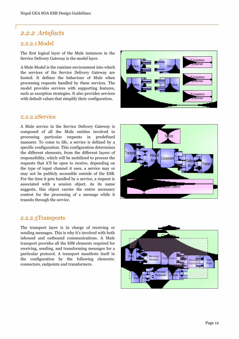
2.2.2.1 Model
The first logical layer of the Mule instances in the
Service Delivery Gateway is the model layer.
A Mule Model is the runtime environment into which
the services of the Service Delivery Gateway are
hosted. It defines the behaviour of Mule when
processing requests handled by these services. The
model provides services with supporting features,
such as exception strategies. It also provides services
with default values that simplify their configuration.
2.2.2.2 Service
A Mule service in the Service Delivery Gateway is
composed of all the Mule entities involved in
processing particular requests in predefined
manners. To come to life, a service is defined by a
specific configuration. This configuration determines
the different elements, from the different layers of
responsibility, which will be mobilized to process the
requests that it‟ll be open to receive, depending on
the type of input channel it uses, a service may or
may not be publicly accessible outside of the ESB.
For the time it gets handled by a service, a request is
associated with a session object. As its name
suggests, this object carries the entire necessary
context for the processing of a message while it
transits through the service.
2.2.2.3 Transports
The transport layer is in charge of receiving or
sending messages. This is why it‟s involved with both
inbound and outbound communications. A Mule
transport provides all the ESB elements required for
receiving, sending, and transforming messages for a
particular protocol. A transport manifests itself in
the configuration by the following elements:
connectors, endpoints and transformers.
Service Service
ServiceService
Exception
Listener
Exception
Listener
Exception
Listener
TransportInbound
Router Outbound
Router
Component
Exception Listener
Service
Transport
Message
Receiver Message
Dispatcher
TransformersEnd
Point
Exception
Listener
Message
RequesterEnd
Point
Connector
End
Point
Transport
Nepal GEA SOA ESB Design Guidelines
Page 13
2.2.2.3.1 Connector
A connector is in charge of controlling the usage of a particular protocol. It‟s configured with parameters that
are specific to this protocol and holds any state that can be shared with the underlying entities in charge of the
actual communications. For example, a HTTP SOAP connector is configured with a Web Service, which is
shared by the different entities in charge of the actual communication. These communicating entities will differ
depending on whether the connector is used for listening/polling, reading from, or writing to a particular
destination: they would respectively be message receivers, message requesters, and message dispatchers.
Though a connector isn‟t part of a service, it contributes these communication parts to it. Consequently, a
service is dependent on one or more connectors for actually receiving or sending messages.
2.2.2.3.2 Endpoint
An endpoint represents the specific usage of a protocol, whether it‟s for listening/polling, reading from
(requesting in Mule‟s terminology), or writing to a particular target destination. It hence controls what
underlying entities will be used with the connector they depend on. The target destination itself is defined as a
URI. Depending on the connector, the URI will bear a different meaning; for example, it can represent a URL or
a JMS destination. Inbound and outbound endpoints exist in the context of a particular service and represent
the expected entry and exit points for messages, respectively. These endpoints are defined in the inbound and
outbound routers. It‟s also possible to define an inbound endpoint in a response router. In that case, the
inbound endpoint acts as a response endpoint where asynchronous replies will be consolidated before the
service returns its own response. Global endpoints can be considered abstract entities that get reified only when
referenced in the context of a service: as such, they‟re a convenient way to share common configuration
attributes.
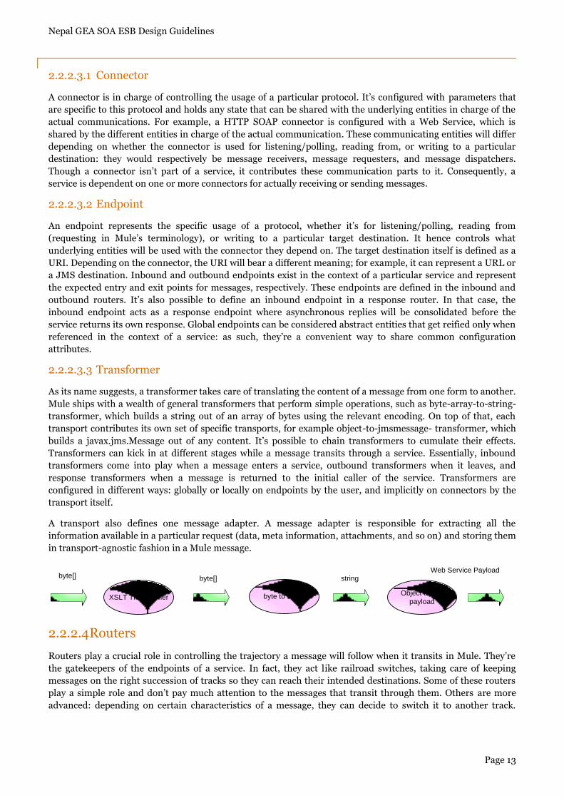
2.2.2.3.3 Transformer
As its name suggests, a transformer takes care of translating the content of a message from one form to another.
Mule ships with a wealth of general transformers that perform simple operations, such as byte-array-to-string-
transformer, which builds a string out of an array of bytes using the relevant encoding. On top of that, each
transport contributes its own set of specific transports, for example object-to-jmsmessage- transformer, which
builds a javax.jms.Message out of any content. It‟s possible to chain transformers to cumulate their effects.
Transformers can kick in at different stages while a message transits through a service. Essentially, inbound
transformers come into play when a message enters a service, outbound transformers when it leaves, and
response transformers when a message is returned to the initial caller of the service. Transformers are
configured in different ways: globally or locally on endpoints by the user, and implicitly on connectors by the
transport itself.
A transport also defines one message adapter. A message adapter is responsible for extracting all the
information available in a particular request (data, meta information, attachments, and so on) and storing them
in transport-agnostic fashion in a Mule message.
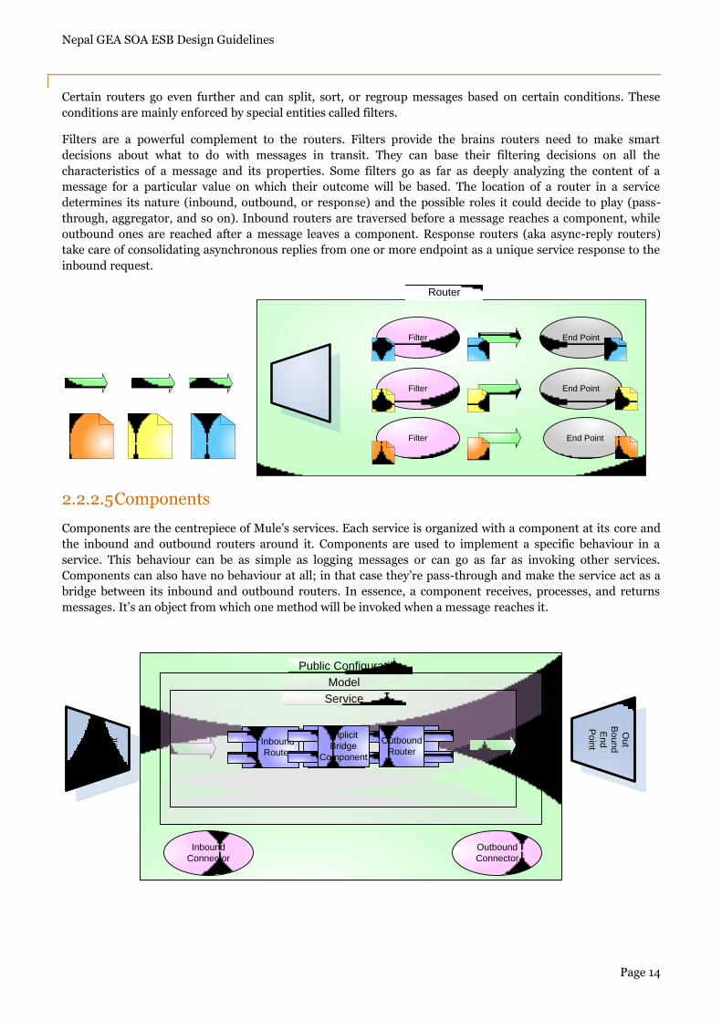
2.2.2.4 Routers
Routers play a crucial role in controlling the trajectory a message will follow when it transits in Mule. They‟re
the gatekeepers of the endpoints of a service. In fact, they act like railroad switches, taking care of keeping
messages on the right succession of tracks so they can reach their intended destinations. Some of these routers
play a simple role and don‟t pay much attention to the messages that transit through them. Others are more
advanced: depending on certain characteristics of a message, they can decide to switch it to another track.
XSLT Transformer byte to string Object to WS
payload
byte[] byte[] stringWeb Service Payload
Nepal GEA SOA ESB Design Guidelines
Page 14
Certain routers go even further and can split, sort, or regroup messages based on certain conditions. These
conditions are mainly enforced by special entities called filters.
Filters are a powerful complement to the routers. Filters provide the brains routers need to make smart
decisions about what to do with messages in transit. They can base their filtering decisions on all the
characteristics of a message and its properties. Some filters go as far as deeply analyzing the content of a
message for a particular value on which their outcome will be based. The location of a router in a service
determines its nature (inbound, outbound, or response) and the possible roles it could decide to play (pass-
through, aggregator, and so on). Inbound routers are traversed before a message reaches a component, while
outbound ones are reached after a message leaves a component. Response routers (aka async-reply routers)
take care of consolidating asynchronous replies from one or more endpoint as a unique service response to the
inbound request.
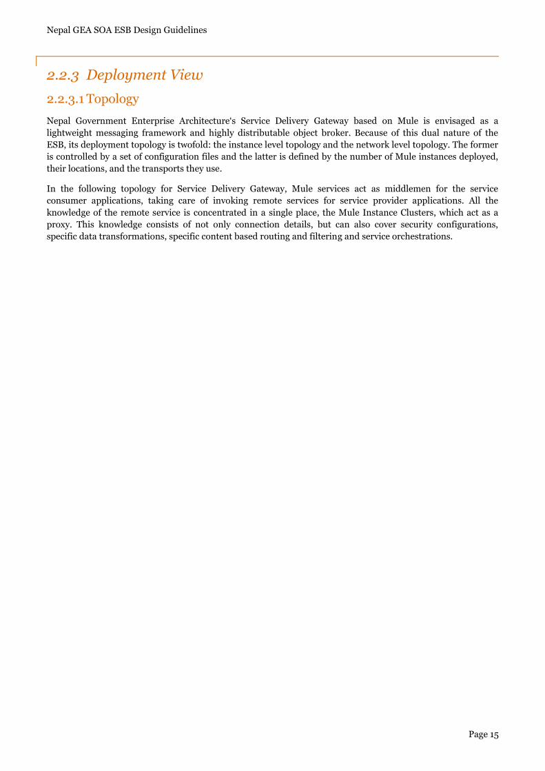
2.2.2.5 Components
Components are the centrepiece of Mule‟s services. Each service is organized with a component at its core and
the inbound and outbound routers around it. Components are used to implement a specific behaviour in a
service. This behaviour can be as simple as logging messages or can go as far as invoking other services.
Components can also have no behaviour at all; in that case they‟re pass-through and make the service act as a
bridge between its inbound and outbound routers. In essence, a component receives, processes, and returns
messages. It‟s an object from which one method will be invoked when a message reaches it.
End PointFilter
Filter
End Point
End Point
Filter
Router
Public Configuration
Model
Inbound
RouterService
Outbound
Router
Implicit
Bridge
Component
Service
In
Bo
un
d
En
d
Po
int
Ou
t
Bo
un
d
En
d
Po
int
Inbound
Connector
Outbound
Connector
Nepal GEA SOA ESB Design Guidelines
Page 15
2.2.3 Deployment View
2.2.3.1 Topology
Nepal Government Enterprise Architecture„s Service Delivery Gateway based on Mule is envisaged as a
lightweight messaging framework and highly distributable object broker. Because of this dual nature of the
ESB, its deployment topology is twofold: the instance level topology and the network level topology. The former
is controlled by a set of configuration files and the latter is defined by the number of Mule instances deployed,
their locations, and the transports they use.
In the following topology for Service Delivery Gateway, Mule services act as middlemen for the service
consumer applications, taking care of invoking remote services for service provider applications. All the
knowledge of the remote service is concentrated in a single place, the Mule Instance Clusters, which act as a
proxy. This knowledge consists of not only connection details, but can also cover security configurations,
specific data transformations, specific content based routing and filtering and service orchestrations.
Nepal GEA SOA ESB Design Guidelines
Page 16
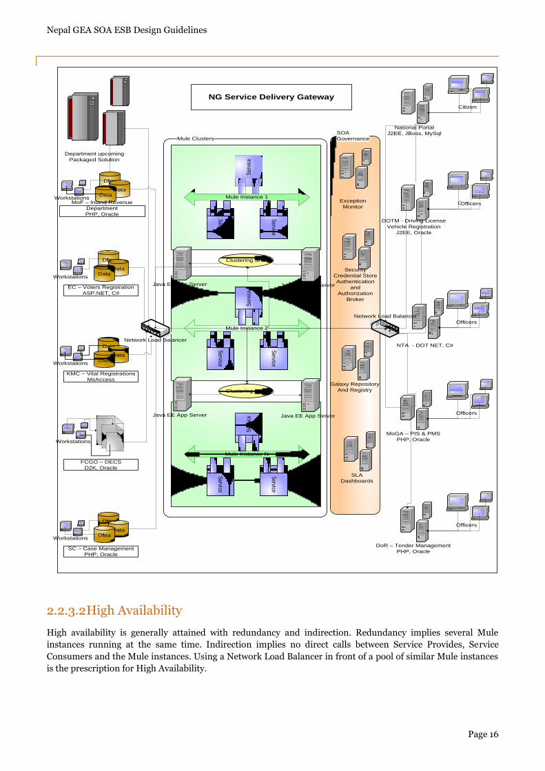
2.2.3.2 High Availability
High availability is generally attained with redundancy and indirection. Redundancy implies several Mule
instances running at the same time. Indirection implies no direct calls between Service Provides, Service
Consumers and the Mule instances. Using a Network Load Balancer in front of a pool of similar Mule instances
is the prescription for High Availability.
Exception
Monitors
And
SLA Dashboards
SOA
GovernanceMule Clusters
Mule Instance 2S
ervice
Service
Ser
vice
Mule Instance N
Service
Service
Ser
vice
Mule Instance 1
Service
Service
Ser
vice
Java EE App ServerJava EE App Server
Clustering S/W
Java EE App ServerJava EE App Server
Clustering S/W
Galaxy Repository
And Registry
SLA
Dashboards
Security
Credential Store
Authentication
and
Authorization
Broker
National Portal
J2EE, JBoss, MySql
Citizen
DOTM - Driving License
Vehicle Registration
J2EE, Oracle
CitizenOfficers
NTA - DOT NET, C#
Officers
MoGA – PIS & PMS
PHP, Oracle
Officers
DoR – Tender Management
PHP, Oracle
Officers
Department upcoming
Packaged Solution
Data
DataData
MoF – Inland Revenue
Department
PHP, Oracle
Workstations
Data
DataData
EC – Voters Registration
ASP.NET, C#
Workstations
Data
DataData
KMC – Vital Registrations
MsAccess
Workstations
Workstations
FCGO – DECS
D2K, Oracle
Data
DataData
SC – Case Management
PHP, Oracle
Workstations
Exception
Monitor
NG Service Delivery Gateway
Network Load Balancer
Network Load Balancer
Nepal GEA SOA ESB Design Guidelines
Page 17
With Network Load Balancer in place, one Mule instance can be taken down, for example for an upgrade, and
the Producer and Consumer applications will still be able to communicate via an active instance. As the name
suggests, using a load balancer would also allow to handle increases in load gracefully: it will always be possible
to add a new Mule instance to the pool and have it handle the load.
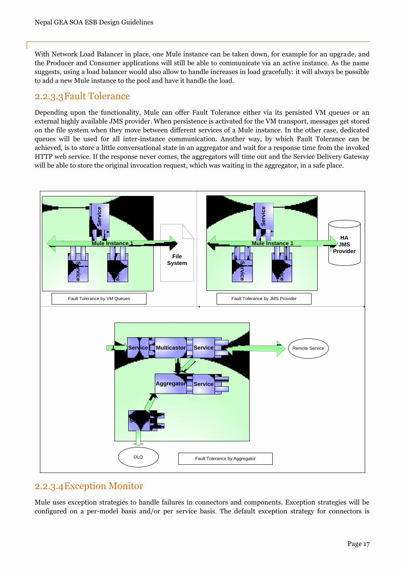
2.2.3.3 Fault Tolerance
Depending upon the functionality, Mule can offer Fault Tolerance either via its persisted VM queues or an
external highly available JMS provider. When persistence is activated for the VM transport, messages get stored
on the file system when they move between different services of a Mule instance. In the other case, dedicated
queues will be used for all inter-instance communication. Another way, by which Fault Tolerance can be
achieved, is to store a little conversational state in an aggregator and wait for a response time from the invoked
HTTP web service. If the response never comes, the aggregators will time out and the Service Delivery Gateway
will be able to store the original invocation request, which was waiting in the aggregator, in a safe place.
2.2.3.4 Exception Monitor
Mule uses exception strategies to handle failures in connectors and components. Exception strategies will be
configured on a per-model basis and/or per service basis. The default exception strategy for connectors is
HA
JMS
ProviderFile
System
Se
rvic
e
Se
rvic
e
Se
rvic
e
Se
rvic
e
Se
rvic
e
Se
rvic
e
Mule Instance 1Mule Instance 1
Service Multicastor Service
Aggregator Service
Service
Remote Service
DLQ
Fault Tolerance by VM Queues Fault Tolerance by JMS Provider
Fault Tolerance by Aggregator
Nepal GEA SOA ESB Design Guidelines
Page 18
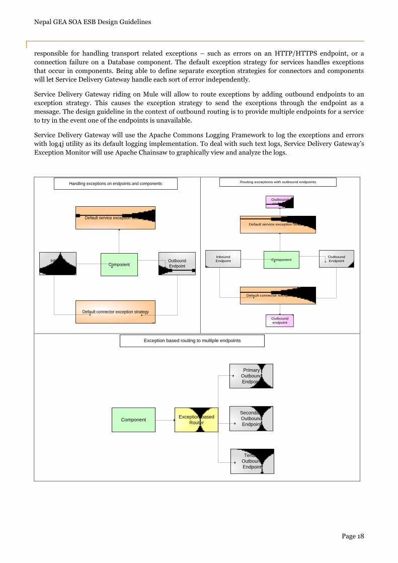
responsible for handling transport related exceptions – such as errors on an HTTP/HTTPS endpoint, or a
connection failure on a Database component. The default exception strategy for services handles exceptions
that occur in components. Being able to define separate exception strategies for connectors and components
will let Service Delivery Gateway handle each sort of error independently.
Service Delivery Gateway riding on Mule will allow to route exceptions by adding outbound endpoints to an
exception strategy. This causes the exception strategy to send the exceptions through the endpoint as a
message. The design guideline in the context of outbound routing is to provide multiple endpoints for a service
to try in the event one of the endpoints is unavailable.
Service Delivery Gateway will use the Apache Commons Logging Framework to log the exceptions and errors
with log4j utility as its default logging implementation. To deal with such text logs, Service Delivery Gateway‟s
Exception Monitor will use Apache Chainsaw to graphically view and analyze the logs.
Default service exception strategy
Inbound
Endpoint ComponentOutbound
Endpoint
Default connector exception strategy
Handling exceptions on endpoints and components
Default service exception strategy
Inbound
Endpoint ComponentOutbound
Endpoint
Default connector exception strategy
Routing exceptions with outbound endpoints
Outbound
endpoint
Outbound
endpoint
ComponentException based
Router
Primary
Outbound
Endpoint
Secondary
Outbound
Endpoint
Tertiary
Outbound
Endpoint
Exception based routing to multiple endpoints
Nepal GEA SOA ESB Design Guidelines
Page 19
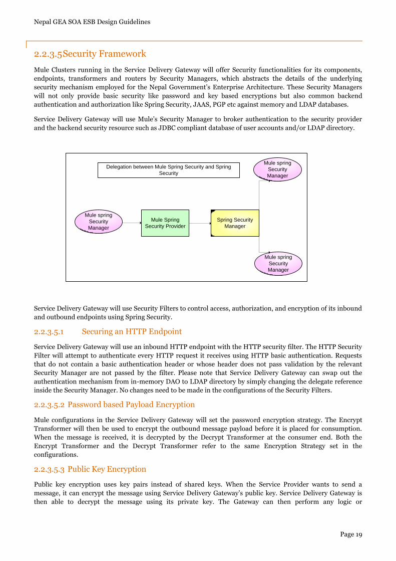
2.2.3.5 Security Framework
Mule Clusters running in the Service Delivery Gateway will offer Security functionalities for its components,
endpoints, transformers and routers by Security Managers, which abstracts the details of the underlying
security mechanism employed for the Nepal Government‟s Enterprise Architecture. These Security Managers
will not only provide basic security like password and key based encryptions but also common backend
authentication and authorization like Spring Security, JAAS, PGP etc against memory and LDAP databases.
Service Delivery Gateway will use Mule‟s Security Manager to broker authentication to the security provider
and the backend security resource such as JDBC compliant database of user accounts and/or LDAP directory.
Service Delivery Gateway will use Security Filters to control access, authorization, and encryption of its inbound
and outbound endpoints using Spring Security.
2.2.3.5.1 Securing an HTTP Endpoint
Service Delivery Gateway will use an inbound HTTP endpoint with the HTTP security filter. The HTTP Security
Filter will attempt to authenticate every HTTP request it receives using HTTP basic authentication. Requests
that do not contain a basic authentication header or whose header does not pass validation by the relevant
Security Manager are not passed by the filter. Please note that Service Delivery Gateway can swap out the
authentication mechanism from in-memory DAO to LDAP directory by simply changing the delegate reference
inside the Security Manager. No changes need to be made in the configurations of the Security Filters.
2.2.3.5.2 Password based Payload Encryption
Mule configurations in the Service Delivery Gateway will set the password encryption strategy. The Encrypt
Transformer will then be used to encrypt the outbound message payload before it is placed for consumption.
When the message is received, it is decrypted by the Decrypt Transformer at the consumer end. Both the
Encrypt Transformer and the Decrypt Transformer refer to the same Encryption Strategy set in the
configurations.
2.2.3.5.3 Public Key Encryption
Public key encryption uses key pairs instead of shared keys. When the Service Provider wants to send a
message, it can encrypt the message using Service Delivery Gateway‟s public key. Service Delivery Gateway is
then able to decrypt the message using its private key. The Gateway can then perform any logic or
Mule spring
Security
Manager
Mule Spring
Security Provider
Spring Security
Manager
Mule spring
Security
Manager
Mule spring
Security
Manager
Delegation between Mule Spring Security and Spring
Security
Nepal GEA SOA ESB Design Guidelines
Page 20
transformations on the payload and can again transmit using the Service Consumer‟s public key. Signing and
verification can also be similarly done to guarantee the authenticity of the message.
PGP is a popular protocol for performing public key encryptions. Mule Clusters in the Service Delivery Gateway
will use the Cryptix library‟s PGP support in the abstraction of Security Filters to perform decryption and
signature verification of messages.
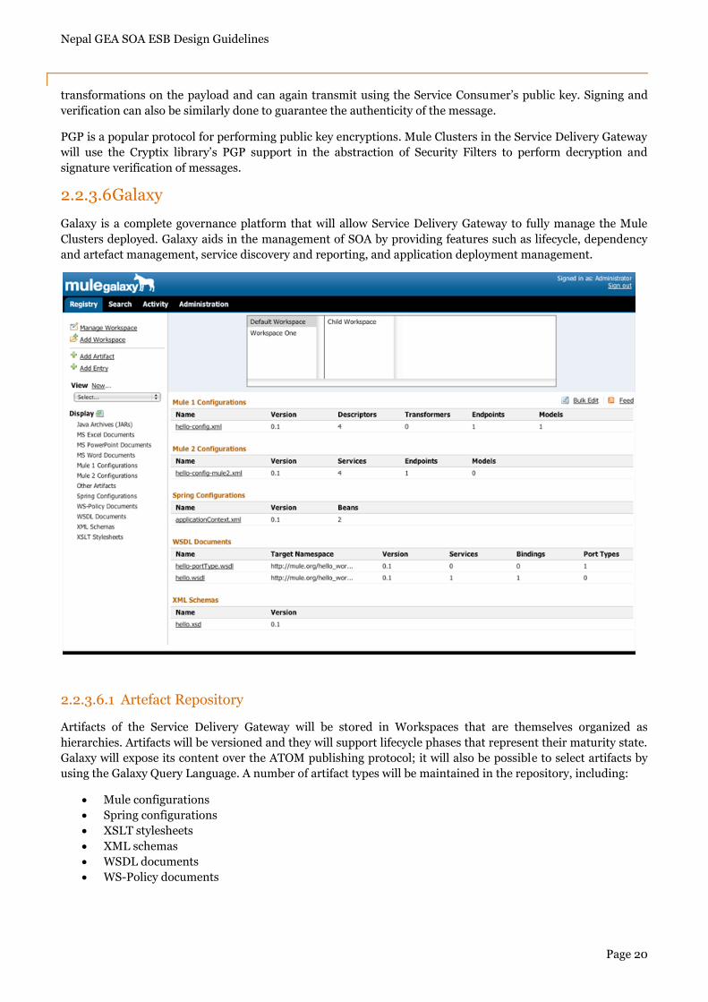
2.2.3.6 Galaxy
Galaxy is a complete governance platform that will allow Service Delivery Gateway to fully manage the Mule
Clusters deployed. Galaxy aids in the management of SOA by providing features such as lifecycle, dependency
and artefact management, service discovery and reporting, and application deployment management.
2.2.3.6.1 Artefact Repository
Artifacts of the Service Delivery Gateway will be stored in Workspaces that are themselves organized as
hierarchies. Artifacts will be versioned and they will support lifecycle phases that represent their maturity state.
Galaxy will expose its content over the ATOM publishing protocol; it will also be possible to select artifacts by
using the Galaxy Query Language. A number of artifact types will be maintained in the repository, including:
Mule configurations
Spring configurations
XSLT stylesheets
XML schemas
WSDL documents
WS-Policy documents
Nepal GEA SOA ESB Design Guidelines
Page 21
Artifacts progress through lifecycle phases inside Galaxy. This helps users and administrators make informed
judgments about the state of the artifact and manage each stage of its lifecycle. For example, a QA team can look
for artifacts inside the repository that are in the Developed phase, perform the necessary testing on them, and
migrate them to the Tested phase. There is one default lifecycle in Galaxy. The phases occur in this order:
Created
Developed
Tested
Staged
Deployed
Retired
2.2.3.6.2 Registry
Galaxy will offer a full fledged registry service as it can deduce dependencies between configuration files
including WSDL and XSD (s) used by Mule.
2.2.3.6.3 Governance Platform
Because it understands what it stores, Galaxy will enforce custom policies to ensure that diverse constraints are
respected like enforcing the backward compatibility of all WSDL files. Galaxy also contains an integrated audit
trail system that will allow Service Delivery Gateway to track all repository operations.
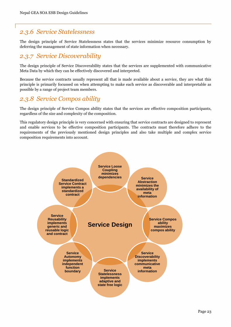
2.3 Service Design Principles
Service orientation represents a design approach comprised of eight specific design principles. Service contracts
adhere to most but not all of these design principles.
2.3.1 Standardized Service Contract
The design principle of Standardized Service Contract states that the services within the same service inventory
are in compliance with the same contract design standards.
Given the name, it is conclusive that this design principle is only about service contracts and the requirements
for them to be consistently standardized within the boundary of a service inventory. This design principle
essentially advocates “contract first” design for services.
2.3.2 Service Loose Coupling
The design principle of Service Loose Coupling states that the service contracts impose low consumer coupling
requirements and are themselves decoupled from their surrounding environment.
This principle also relates to the service contract. Its design and how it is architecturally positioned within the
service architecture are regulated with a strong emphasis on ensuring that only the right type of content makes
its way into the contract in order to avoid the negative coupling types. Following sections enumerate common
types of coupling – all are considered negative coupling types, except for the last.
2.3.2.1 Contract to Functional Coupling
Service contracts can become dependent on outside business processes, especially when they are coupled to
logic that was designed directly in support of these processes. This can result in contract to functional coupling,
whereby the contract expresses characteristics that are specifically related to the parent business logic.
Nepal GEA SOA ESB Design Guidelines
Page 22
2.3.2.2 Contract to Implementation Coupling
When details about a service‟s underlying implementation are embedded within a service contract, an extent of
contract to implementation coupling is formed. This negative coupling type commonly results when service
contracts are a native part of the service implementation or when they are auto-generated and derived from
implementation resources such as legacy APIs, components and databases.
2.3.2.3 Contract to Logic Coupling
The extent to which a service contract is bound to the underlying service programming logic is referred to as
contract to logic coupling. This is considered a negative type of service coupling because service consumer
programs that bind to the service contract end up also inadvertently forming dependencies on the underlying
service logic.
2.3.2.4 Contract to Technology Coupling
When the contract exposed by a service is bound to non standard communication technology, it forms an extent
of contract to technology coupling. Although this coupling type could be applied to the dependencies associated
with any proprietary technology, it is used exclusively for communication technology because that is what
service contracts are generally concerned with.
2.3.2.5 Logic to Contract Coupling
Each of the previously mentioned forms of coupling are considered negative because they can shorten the
lifespan of a Web Service Contract, thereby leading to increased governance burden as a result of having to
manage service contract versions.
2.3.3 Service Abstraction
The design principle of Service Abstraction states that the service contracts contain only essential information
and information about services is limited to what is published in service contracts.
By turning services into black boxes, the contracts are all that is officially available to consumer designers who
want to use the services. While much of this principle is about the controlled hiding of information by service
owners, it also advocates the stream lining of contract content to ensure that only essential content is made
available.
2.3.4 Service Reusability
The design principle of Service Reusability states that services contain and express agnostic logic and can be
positioned as reusable Enterprise Resources.
While this design principle is certainly focussed on ensuring that service logic is designed to be robust and
generic, these qualities also carry over into contract design. When viewing the service as a product and its
contract as a generic API to which potentially many consumer programs will need to interface, the requirement
emerges to ensure that the services‟ functional context, the definition of the capabilities, and the level at which
each of its design granularities are set are appropriate for it to be positioned as a reusable Enterprise resource.
2.3.5 Service Autonomy
The design principle of Service Autonomy states that the services exercise a high level of control over their
underlying runtime execution environment.
Nepal GEA SOA ESB Design Guidelines
Page 23
2.3.6 Service Statelessness
The design principle of Service Statelessness states that the services minimize resource consumption by
deferring the management of state information when necessary.
2.3.7 Service Discoverability
The design principle of Service Discoverability states that the services are supplemented with communicative
Meta Data by which they can be effectively discovered and interpreted.
Because the service contracts usually represent all that is made available about a service, they are what this
principle is primarily focussed on when attempting to make each service as discoverable and interpretable as
possible by a range of project team members.
2.3.8 Service Compos ability
The design principle of Service Compos ability states that the services are effective composition participants,
regardless of the size and complexity of the composition.
This regulatory design principle is very concerned with ensuring that service contracts are designed to represent
and enable services to be effective composition participants. The contracts must therefore adhere to the
requirements of the previously mentioned design principles and also take multiple and complex service
composition requirements into account.
Service Design
Service Loose Coupling minimizes
dependencies Service Abstraction
minimizes the availability of
meta information
Service Compos ability
maximizes compos ability
Service Discoverability
implements communicative
meta informationService
Statelessness implements adaptive and
state free logic
Service Autonomy
implements independent
function boundary
Service Reusability implements generic and
reusable logic and contract
Standardized Service Contract
implements a standardized
contract
Nepal GEA SOA ESB Design Guidelines
Page 24
2.4 Service Design Patterns
Service Design Patterns provide a proven solution to a common problem in context, individually documented in
a consistent format. As with design principles, the following design patterns can be applied to various measures.
2.4.1 Service Inventory Design Patterns
Service Inventory represents a collection on independently standardized and governed services. Design patterns
associated with the design of the service inventory are provided below.
2.4.1.1 Foundational Inventory Patterns
Foundational Inventory Patterns provide the baseline design characteristics of the service inventory.
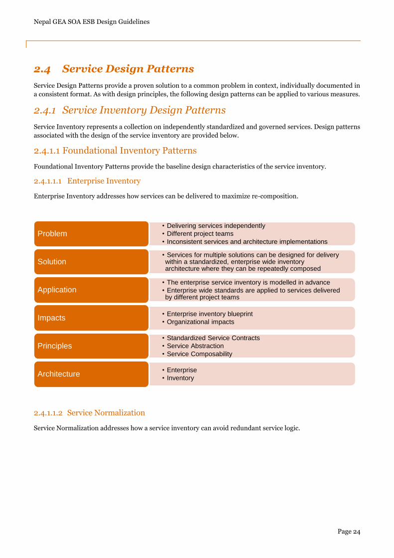
2.4.1.1.1 Enterprise Inventory
Enterprise Inventory addresses how services can be delivered to maximize re-composition.
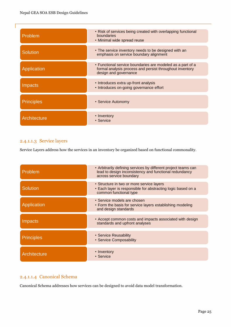
2.4.1.1.2 Service Normalization
Service Normalization addresses how a service inventory can avoid redundant service logic.
• Delivering services independently
• Different project teams
• Inconsistent services and architecture implementationsProblem
• Services for multiple solutions can be designed for delivery within a standardized, enterprise wide inventory architecture where they can be repeatedly composed
Solution
• The enterprise service inventory is modelled in advance
• Enterprise wide standards are applied to services delivered by different project teams
Application
• Enterprise inventory blueprint
• Organizational impactsImpacts
• Standardized Service Contracts
• Service Abstraction
• Service ComposabilityPrinciples
• Enterprise
• InventoryArchitecture
Nepal GEA SOA ESB Design Guidelines
Page 25
2.4.1.1.3 Service layers
Service Layers address how the services in an inventory be organized based on functional commonality.
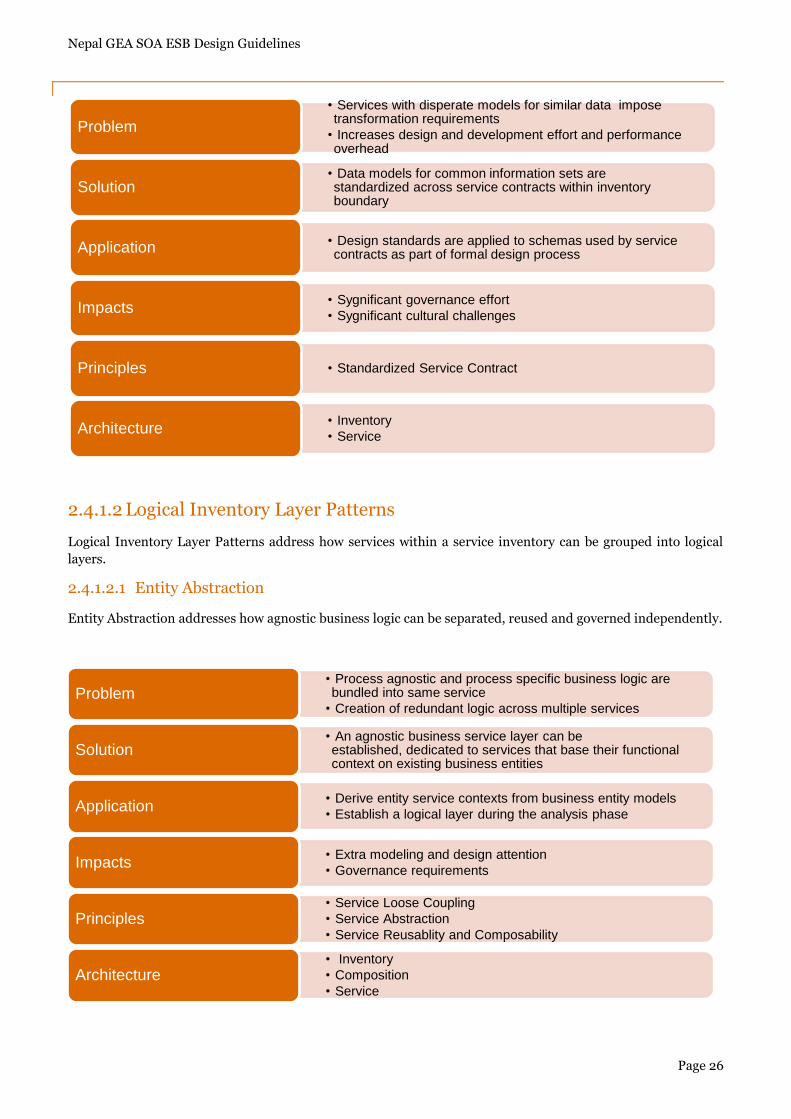
2.4.1.1.4 Canonical Schema
Canonical Schema addresses how services can be designed to avoid data model transformation.
• Risk of services being created with overlapping functional boundaries
• Minimal wide spread reuse Problem
• The service inventory needs to be designed with an emphasis on service boundary alignmentSolution
• Functional service boundaries are modeled as a part of a formal analysis process and persist throughout inventory design and governance
Application
• Introduces extra up-front analysis
• Introduces on-going governance effortImpacts
• Service AutonomyPrinciples
• Inventory
• ServiceArchitecture
• Arbitrarily defining services by different project teams can lead to design inconsistency and functional redundancy across service boundary
Problem
• Structure in two or more service layers
• Each layer is responsible for abstracting logic based on a common functional type
Solution
• Service models are chosen
• Form the basis for service layers establishing modeling and design standards
Application
• Accept common costs and impacts associated with design standards and upfront analysesImpacts
• Service Reusability
• Service ComposabilityPrinciples
• Inventory
• ServiceArchitecture
Nepal GEA SOA ESB Design Guidelines
Page 26
2.4.1.2 Logical Inventory Layer Patterns
Logical Inventory Layer Patterns address how services within a service inventory can be grouped into logical
layers.
2.4.1.2.1 Entity Abstraction
Entity Abstraction addresses how agnostic business logic can be separated, reused and governed independently.
• Services with disperate models for similar data impose transformation requirements
• Increases design and development effort and performance overhead
Problem
• Data models for common information sets are standardized across service contracts within inventory boundary
Solution
• Design standards are applied to schemas used by service contracts as part of formal design processApplication
• Sygnificant governance effort
• Sygnificant cultural challengesImpacts
• Standardized Service ContractPrinciples
• Inventory
• ServiceArchitecture
• Process agnostic and process specific business logic are bundled into same service
• Creation of redundant logic across multiple servicesProblem
• An agnostic business service layer can be established, dedicated to services that base their functional context on existing business entities
Solution
• Derive entity service contexts from business entity models
• Establish a logical layer during the analysis phaseApplication
• Extra modeling and design attention
• Governance requirementsImpacts
• Service Loose Coupling
• Service Abstraction
• Service Reusablity and ComposabilityPrinciples
• Inventory
• Composition
• ServiceArchitecture
Nepal GEA SOA ESB Design Guidelines
Page 27
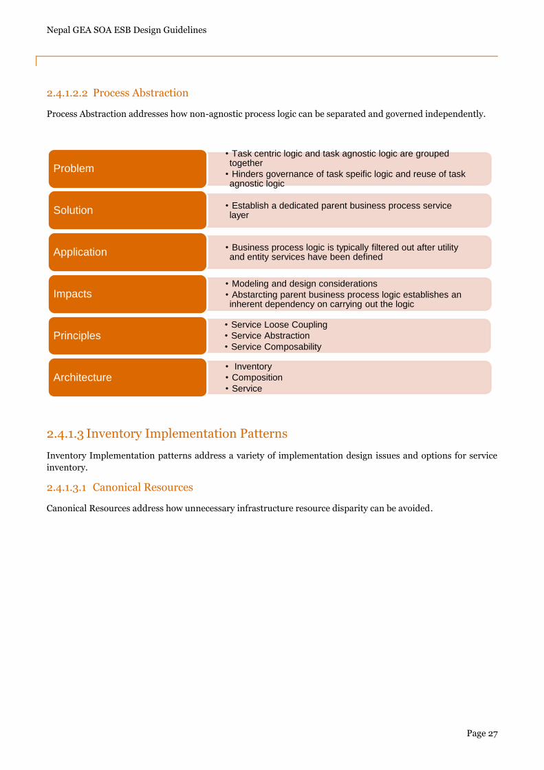
2.4.1.2.2 Process Abstraction
Process Abstraction addresses how non-agnostic process logic can be separated and governed independently.
2.4.1.3 Inventory Implementation Patterns
Inventory Implementation patterns address a variety of implementation design issues and options for service
inventory.
2.4.1.3.1 Canonical Resources
Canonical Resources address how unnecessary infrastructure resource disparity can be avoided.
• Task centric logic and task agnostic logic are grouped together
• Hinders governance of task speific logic and reuse of task agnostic logic
Problem
• Establish a dedicated parent business process service layerSolution
• Business process logic is typically filtered out after utility and entity services have been definedApplication
• Modeling and design considerations
• Abstarcting parent business process logic establishes an inherent dependency on carrying out the logic
Impacts
• Service Loose Coupling
• Service Abstraction
• Service ComposabilityPrinciples
• Inventory
• Composition
• ServiceArchitecture
Nepal GEA SOA ESB Design Guidelines
Page 28
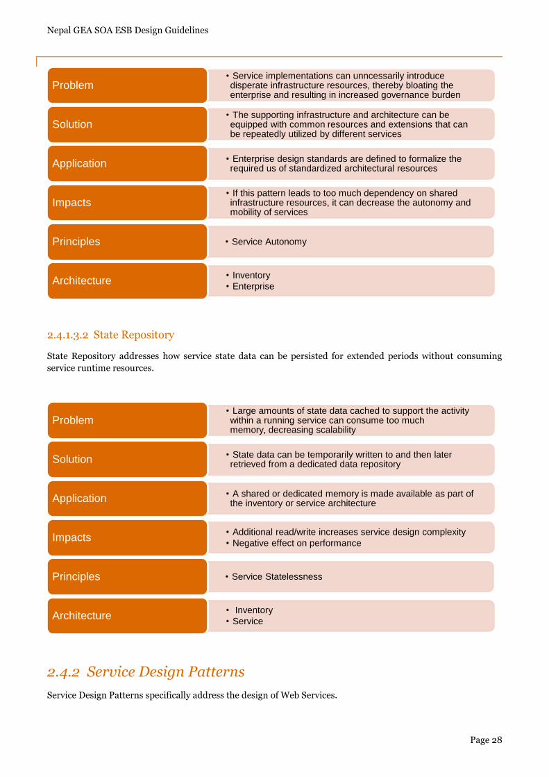
2.4.1.3.2 State Repository
State Repository addresses how service state data can be persisted for extended periods without consuming
service runtime resources.
2.4.2 Service Design Patterns
Service Design Patterns specifically address the design of Web Services.
• Service implementations can unncessarily introduce disperate infrastructure resources, thereby bloating the enterprise and resulting in increased governance burden
Problem
• The supporting infrastructure and architecture can be equipped with common resources and extensions that can be repeatedly utilized by different services
Solution
• Enterprise design standards are defined to formalize the required us of standardized architectural resourcesApplication
• If this pattern leads to too much dependency on shared infrastructure resources, it can decrease the autonomy and mobility of services
Impacts
• Service AutonomyPrinciples
• Inventory
• EnterpriseArchitecture
• Large amounts of state data cached to support the activity within a running service can consume too much memory, decreasing scalability
Problem
• State data can be temporarily written to and then later retrieved from a dedicated data repositorySolution
• A shared or dedicated memory is made available as part of the inventory or service architectureApplication
• Additional read/write increases service design complexity
• Negative effect on performanceImpacts
• Service StatelessnessPrinciples
• Inventory
• ServiceArchitecture
Nepal GEA SOA ESB Design Guidelines
Page 29
2.4.2.1 Foundational Service Patterns
Foundational Service Patterns establish fundamental service design characteristics via suggested application
sequence.
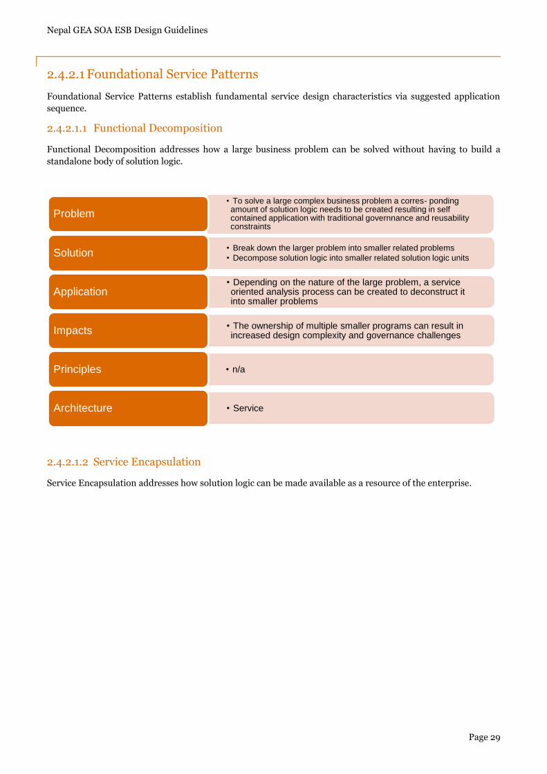
2.4.2.1.1 Functional Decomposition
Functional Decomposition addresses how a large business problem can be solved without having to build a
standalone body of solution logic.
2.4.2.1.2 Service Encapsulation
Service Encapsulation addresses how solution logic can be made available as a resource of the enterprise.
• To solve a large complex business problem a corres- ponding amount of solution logic needs to be created resulting in self contained application with traditional governnance and reusability constraints
Problem
• Break down the larger problem into smaller related problems
• Decompose solution logic into smaller related solution logic unitsSolution
• Depending on the nature of the large problem, a service oriented analysis process can be created to deconstruct it into smaller problems
Application
• The ownership of multiple smaller programs can result in increased design complexity and governance challengesImpacts
• n/aPrinciples
• ServiceArchitecture
Nepal GEA SOA ESB Design Guidelines
Page 30
2.4.2.2 Service Implementation Patterns
Service Implementation patterns provide design solutions for a range of service architecture specific issues
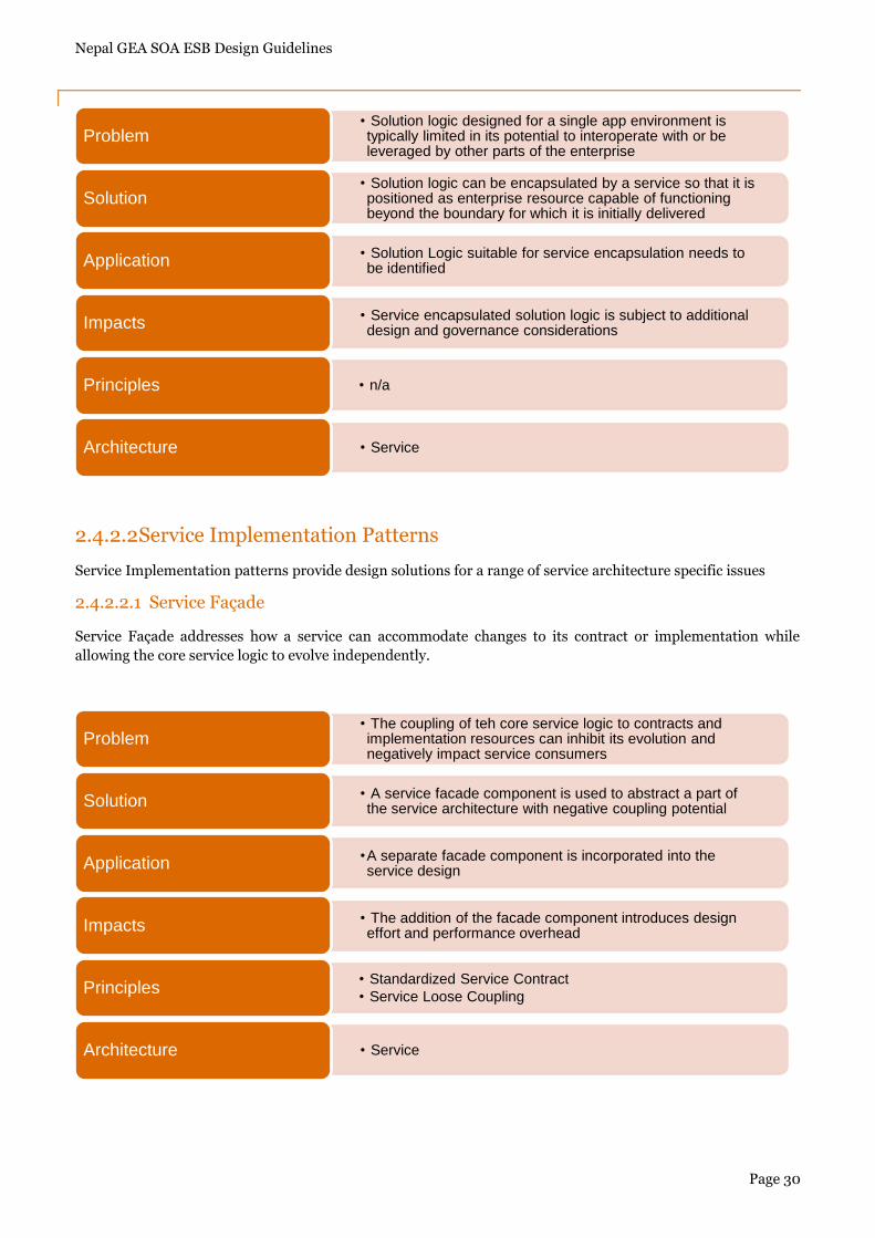
2.4.2.2.1 Service Façade
Service Façade addresses how a service can accommodate changes to its contract or implementation while
allowing the core service logic to evolve independently.
• Solution logic designed for a single app environment is typically limited in its potential to interoperate with or be leveraged by other parts of the enterprise
Problem
• Solution logic can be encapsulated by a service so that it is positioned as enterprise resource capable of functioning beyond the boundary for which it is initially delivered
Solution
• Solution Logic suitable for service encapsulation needs to be identifiedApplication
• Service encapsulated solution logic is subject to additional design and governance considerationsImpacts
• n/aPrinciples
• ServiceArchitecture
• The coupling of teh core service logic to contracts and implementation resources can inhibit its evolution and negatively impact service consumers
Problem
• A service facade component is used to abstract a part of the service architecture with negative coupling potentialSolution
•A separate facade component is incorporated into the service designApplication
• The addition of the facade component introduces design effort and performance overheadImpacts
• Standardized Service Contract
• Service Loose CouplingPrinciples
• ServiceArchitecture

Nepal GEA SOA ESB Design Guidelines
Page 31
2.4.2.2.2 Partial Validation
Partial Validation addresses how unnecessary data validation can be avoided.
2.4.2.2.3 UI Mediator
UI Mediator addresses how a service oriented solution can provide a consistent interactive user experience.
• The generic capabilities provided by agnostic services sometimes result in contracts that impose unnecessary data and validation upon consumer programs
Problem
• A consumer program can be designed to only validate the relevant subset of the data and ignore the remainderSolution
•For web Services, X-Path can be used to filter out necessary data prior to validationApplication
• Extra design time effort
• Runtime data filtering logicImpacts
• Standardized Service Contract
• Service Loose CouplingPrinciples
• CompositionArchitecture
• The consistency with which services respond to user requests originating from an user interface can fluctuate leading to a poor user experience
Problem
• Establish mediator between services layer and presentation logicSolution
•A utility mediator logic is positioned as the initial recipient of messages originating from UI.
• This mediator responds in a timely and consistent mannerApplication
• Additional layer of processing
• Run time processing overheadImpacts
• Service Loose CouplingPrinciples
• CompositionArchitecture
Nepal GEA SOA ESB Design Guidelines
Page 32
2.4.2.3 Service Security Patterns
Service Security Patterns primarily shape the internal logic of services to equip them with security controls that
encounter common threats.
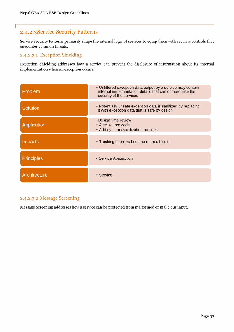
2.4.2.3.1 Exception Shielding
Exception Shielding addresses how a service can prevent the disclosure of information about its internal
implementation when an exception occurs.
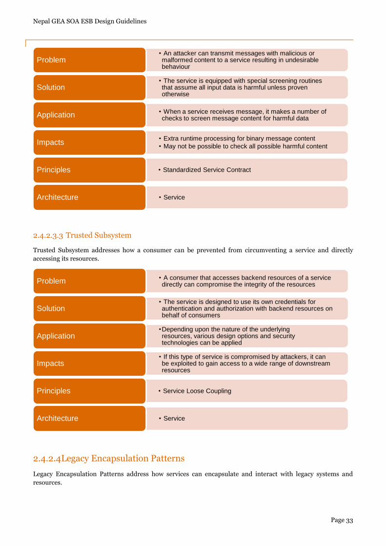
2.4.2.3.2 Message Screening
Message Screening addresses how a service can be protected from malformed or malicious input.
• Unfiltered exception data output by a service may contain internal implementation details that can compromise the security of the services
Problem
• Potentially unsafe exception data is sanitized by replacing it with exception data that is safe by designSolution
•Design time review
• Alter source code
• Add dynamic sanitization routinesApplication
• Tracking of errors become more difficultImpacts
• Service AbstractionPrinciples
• ServiceArchitecture
Nepal GEA SOA ESB Design Guidelines
Page 33
2.4.2.3.3 Trusted Subsystem
Trusted Subsystem addresses how a consumer can be prevented from circumventing a service and directly
accessing its resources.
2.4.2.4 Legacy Encapsulation Patterns
Legacy Encapsulation Patterns address how services can encapsulate and interact with legacy systems and
resources.
• An attacker can transmit messages with malicious or malformed content to a service resulting in undesirable behaviour
Problem
• The service is equipped with special screening routines that assume all input data is harmful unless proven otherwise
Solution
• When a service receives message, it makes a number of checks to screen message content for harmful dataApplication
• Extra runtime processing for binary message content
• May not be possible to check all possible harmful contentImpacts
• Standardized Service ContractPrinciples
• ServiceArchitecture
• A consumer that accesses backend resources of a service directly can compromise the integrity of the resourcesProblem
• The service is designed to use its own credentials for authentication and authorization with backend resources on behalf of consumers
Solution
•Depending upon the nature of the underlying resources, various design options and security technologies can be applied
Application
• If this type of service is compromised by attackers, it can be exploited to gain access to a wide range of downstream resources
Impacts
• Service Loose CouplingPrinciples
• ServiceArchitecture
Nepal GEA SOA ESB Design Guidelines
Page 34
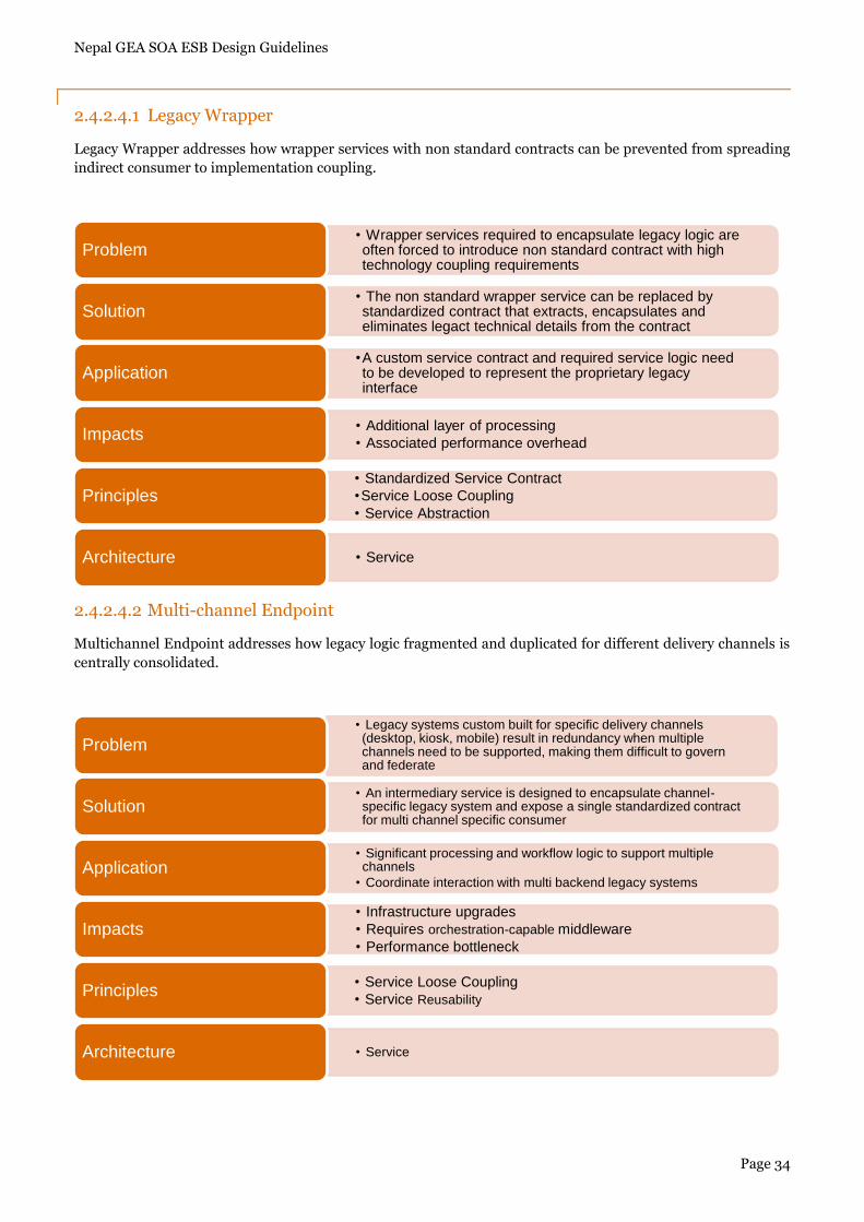
2.4.2.4.1 Legacy Wrapper
Legacy Wrapper addresses how wrapper services with non standard contracts can be prevented from spreading
indirect consumer to implementation coupling.
2.4.2.4.2 Multi-channel Endpoint
Multichannel Endpoint addresses how legacy logic fragmented and duplicated for different delivery channels is
centrally consolidated.
• Wrapper services required to encapsulate legacy logic are often forced to introduce non standard contract with high technology coupling requirements
Problem
• The non standard wrapper service can be replaced by standardized contract that extracts, encapsulates and eliminates legact technical details from the contract
Solution
•A custom service contract and required service logic need to be developed to represent the proprietary legacy interface
Application
• Additional layer of processing
• Associated performance overheadImpacts
• Standardized Service Contract
•Service Loose Coupling
• Service AbstractionPrinciples
• ServiceArchitecture
• Legacy systems custom built for specific delivery channels (desktop, kiosk, mobile) result in redundancy when multiple channels need to be supported, making them difficult to govern and federate
Problem
• An intermediary service is designed to encapsulate channel-specific legacy system and expose a single standardized contract for multi channel specific consumer
Solution
• Significant processing and workflow logic to support multiple channels
• Coordinate interaction with multi backend legacy systemsApplication
• Infrastructure upgrades
• Requires orchestration-capable middleware
• Performance bottleneckImpacts
• Service Loose Coupling
• Service ReusabilityPrinciples
• ServiceArchitecture
Nepal GEA SOA ESB Design Guidelines
Page 35
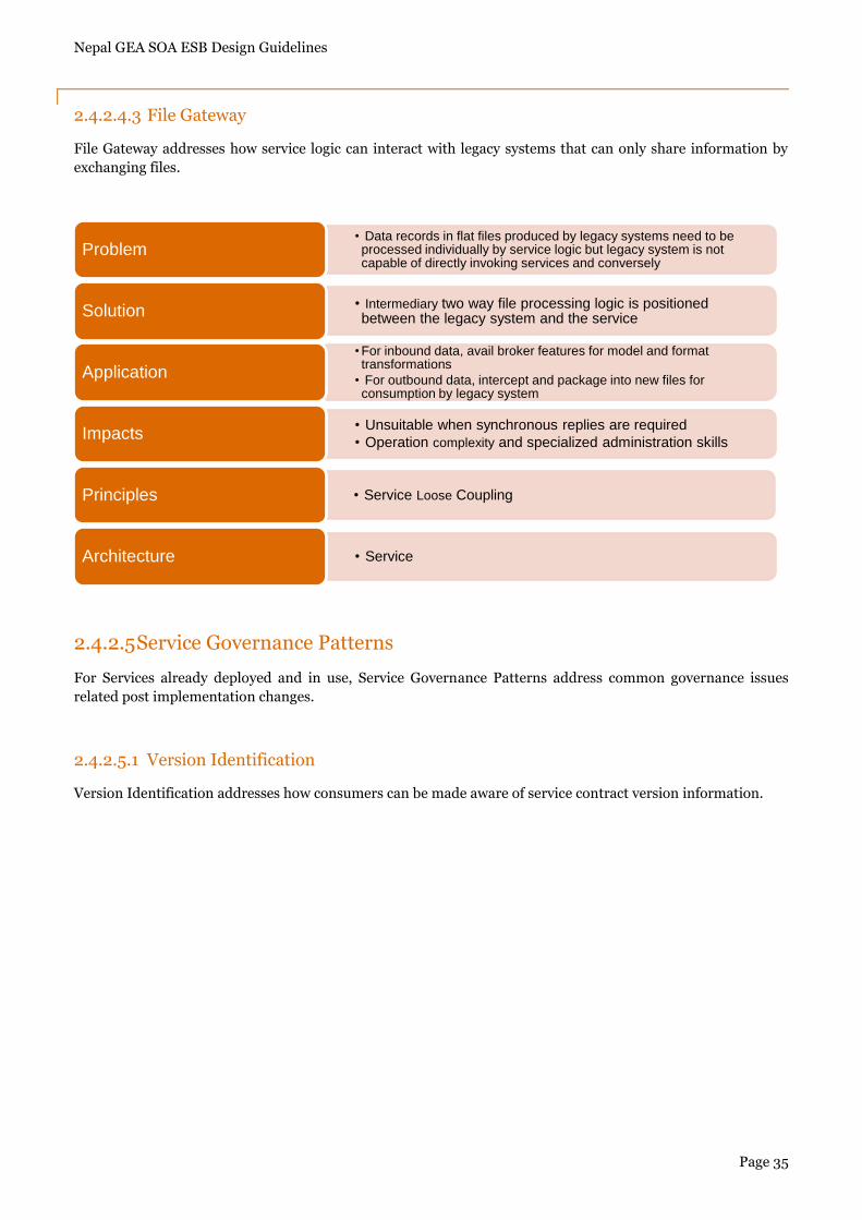
2.4.2.4.3 File Gateway
File Gateway addresses how service logic can interact with legacy systems that can only share information by
exchanging files.
2.4.2.5 Service Governance Patterns
For Services already deployed and in use, Service Governance Patterns address common governance issues
related post implementation changes.
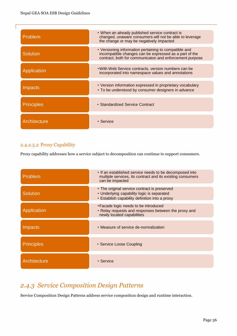
2.4.2.5.1 Version Identification
Version Identification addresses how consumers can be made aware of service contract version information.
• Data records in flat files produced by legacy systems need to be processed individually by service logic but legacy system is not capable of directly invoking services and conversely
Problem
• Intermediary two way file processing logic is positioned between the legacy system and the serviceSolution
• For inbound data, avail broker features for model and format transformations
• For outbound data, intercept and package into new files for consumption by legacy system
Application
• Unsuitable when synchronous replies are required
• Operation complexity and specialized administration skillsImpacts
• Service Loose CouplingPrinciples
• ServiceArchitecture
Nepal GEA SOA ESB Design Guidelines
Page 36
2.4.2.5.2 Proxy Capability
Proxy capability addresses how a service subject to decomposition can continue to support consumers.
2.4.3 Service Composition Design Patterns
Service Composition Design Patterns address service composition design and runtime interaction.
• When an already published service contract is changed, unaware consumers will not be able to leverage the change or may be negatively impacted
Problem
• Versioning information pertaining to compatible and incompatible changes can be expressed as a part of the contract, both for communicaton and enforcement purpose
Solution
•With Web Service contracts, version numbers can be incorporated into namespace values and annotationsApplication
• Version information expressed in proprietary vocabulary
• To be understood by consumer designers in advanceImpacts
• Standardized Service ContractPrinciples
• ServiceArchitecture
• If an established service needs to be decomposed into multiple services, its contract and its existing consumers can be impacted
Problem
• The original service contract is preserved
• Underlying capability logic is separated
• Establish capability definition into a proxySolution
•Facade logic needs to be introduced
• Relay requests and responses between the proxy and newly located capabilities
Application
• Measure of service de-normalizationImpacts
• Service Loose CouplingPrinciples
• ServiceArchitecture
Nepal GEA SOA ESB Design Guidelines
Page 37
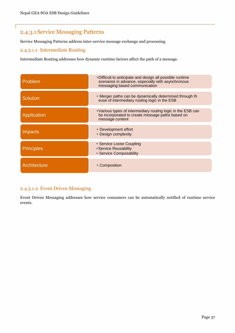
2.4.3.1 Service Messaging Patterns
Service Messaging Patterns address inter-service message exchange and processing.
2.4.3.1.1 Intermediate Routing
Intermediate Routing addresses how dynamic runtime factors affect the path of a message.
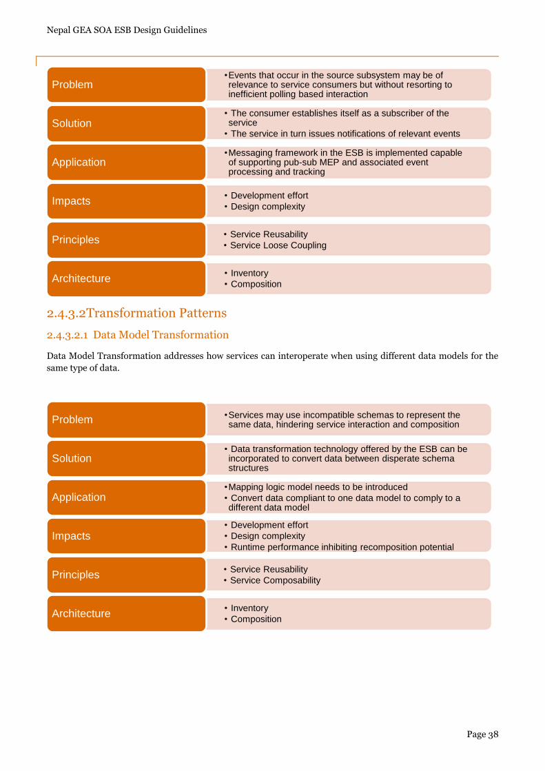
2.4.3.1.2 Event Driven Messaging
Event Driven Messaging addresses how service consumers can be automatically notified of runtime service
events.
•Difficult to anticipate and design all possible runtime scenarios in advance, especially with asynchronous messaging based communication
Problem
• Merger paths can be dynamically determined through th euse of intermediary routing logic in the ESBSolution
•Various types of intermediary routing logic in the ESB can be incorporated to create message paths based on message content
Application
• Development effort
• Design complexityImpacts
• Service Loose Coupling
•Service Reusability
• Service ComposabilityPrinciples
• CompositionArchitecture
Nepal GEA SOA ESB Design Guidelines
Page 38
2.4.3.2 Transformation Patterns
2.4.3.2.1 Data Model Transformation
Data Model Transformation addresses how services can interoperate when using different data models for the
same type of data.
•Events that occur in the source subsystem may be of relevance to service consumers but without resorting to inefficient polling based interaction
Problem
• The consumer establishes itself as a subscriber of the service
• The service in turn issues notifications of relevant eventsSolution
•Messaging framework in the ESB is implemented capable of supporting pub-sub MEP and associated event processing and tracking
Application
• Development effort
• Design complexityImpacts
• Service Reusability
• Service Loose CouplingPrinciples
• Inventory
• CompositionArchitecture
•Services may use incompatible schemas to represent the same data, hindering service interaction and compositionProblem
• Data transformation technology offered by the ESB can be incorporated to convert data between disperate schema structures
Solution
•Mapping logic model needs to be introduced
• Convert data compliant to one data model to comply to a different data model
Application
• Development effort
• Design complexity
• Runtime performance inhibiting recomposition potentialImpacts
• Service Reusability
• Service ComposabilityPrinciples
• Inventory
• CompositionArchitecture
Nepal GEA SOA ESB Design Guidelines
Page 39
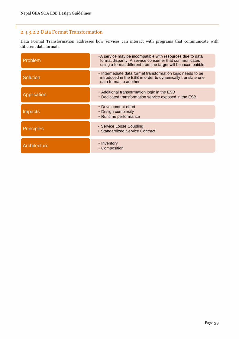
2.4.3.2.2 Data Format Transformation
Data Format Transformation addresses how services can interact with programs that communicate with
different data formats.
•A service may be incompatible with resources due to data format disparity. A service consumer that communicates using a format different from the target will be incompatible
Problem
• Intermediate data format transformation logic needs to be introduced in the ESB in order to dynamically translate one data format to another
Solution
• Additional transofrmation logic in the ESB
• Dedicated transformation service exposed in the ESBApplication
• Development effort
• Design complexity
• Runtime performanceImpacts
• Service Loose Coupling
• Standardized Service ContractPrinciples
• Inventory
• CompositionArchitecture
Nepal GEA SOA ESB Design Guidelines
Page 40
2.5 Guidelines on Enabling Services for Applications
The applications in the IT landscape of Nepal Government departments can be widely classified into the
following set of platforms: Web based J2EE applications, Microsoft ASP DOT NET applications, Web based
PHP applications and two tier applications with a Microsoft Access database. In order to expose the Business
Services provided by these applications in the Service Delivery gateway, all these applications needs to be Web
Service enabled. By being Web Service enabled, all these Business Services can be invoked by any other in the
wider scope of the IT landscape. More pertinently, any departmental application or Portal can avail these Web
enabled Business Services via the Service Delivery Gateway. All other consumers will imagine the Service
Delivery Gateway as the provider of all the required Business Services and the gateway in turn will proxy,
mediate and aggregate these services provided by all other departmental applications.
2.5.1 Prerequisites
Following assumptions or prerequisites will seem to be relevant for the providers i.e. the applications in the
departments providing the Business Services:
The departmental application has LAN/WAN connectivity with the Service Delivery Gateway.
The IT infrastructure hosting the Web Services of the departmental applications are robust enough to
cater to the multitude of consumers across the Nepal Government‟s IT landscape.
The Business Services hosted by the department applications abide by the schema, contracts, semantics
and syntaxes specified by
Reliability, performance, scalability, fault tolerance and high availability features have been addressed
in the design and implementation of the departmental applications.
In case of the two tier applications with the database like MS Access being primary custodian of the
Business Services, the features of reliability, performance, scalability, fault tolerance and high
availability features are provided by the database design and implementation.
The Business Services provided by the departmental IT conform to the security provisions of the Nepal
GEA Security specifications.
The departmental IT participate in the Governance Strategies and Measures of the Service Delivery
Gateway for maintaining the respective Business Services, adding newer versions, adding newer
services, deprecating the older versions etc
The hosts, ports and other connection information with respect to availability, monitoring, load
balancing etc are made available to the Service Delivery Gateway Governance team
2.5.2 Web Based J2EE applications
There can be two approaches; one can take, in enabling the Business Services over the web. In the Contract first
approach, start from the WDSL that has been prescribed by the Service Specifications team and the other is the
Implementation first approach where the output WSDL is matched with that of the Service Specifications. Steps
for the two approaches are enumerated below.
Contract First: In this approach, the WSDL specified by the EA recommendations, serve as the starting
point for generating the Web Services for the business functionalities.
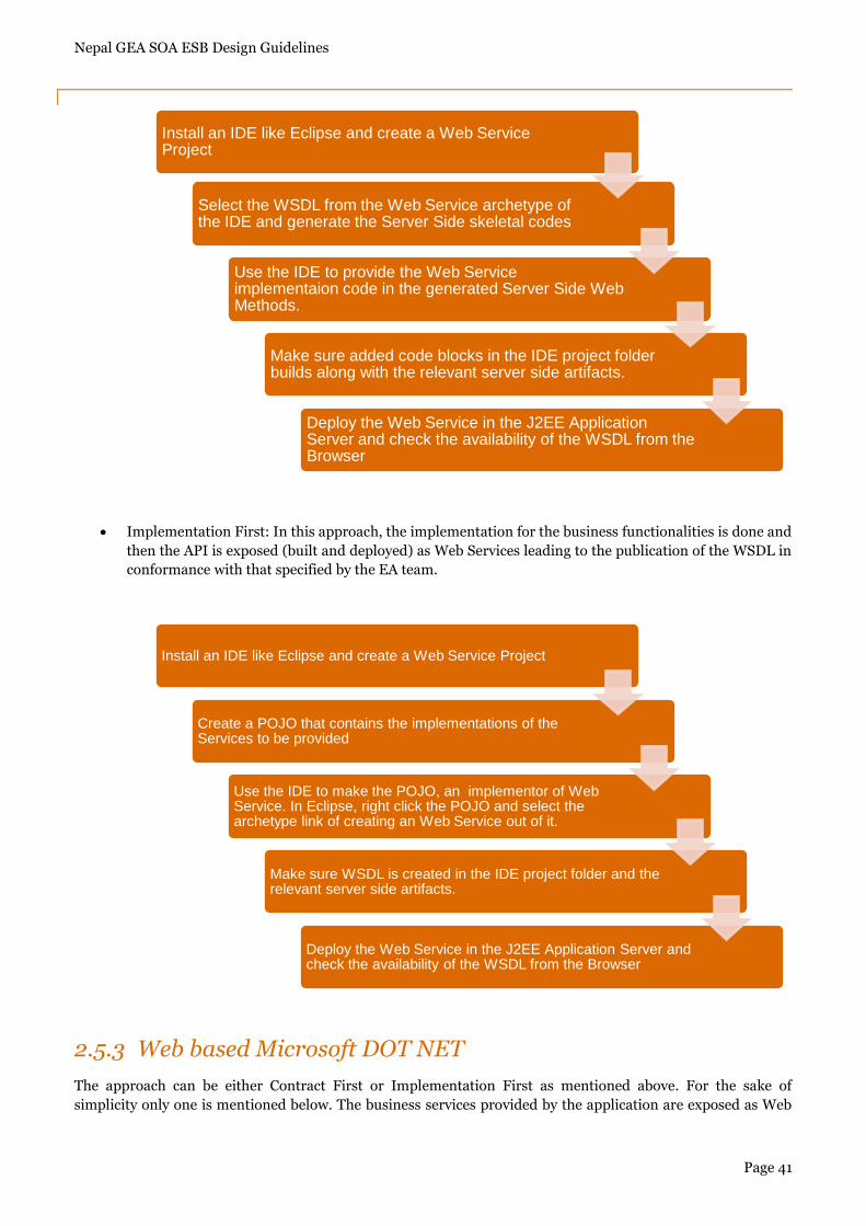
Nepal GEA SOA ESB Design Guidelines
Page 41
Implementation First: In this approach, the implementation for the business functionalities is done and
then the API is exposed (built and deployed) as Web Services leading to the publication of the WSDL in
conformance with that specified by the EA team.
2.5.3 Web based Microsoft DOT NET
The approach can be either Contract First or Implementation First as mentioned above. For the sake of
simplicity only one is mentioned below. The business services provided by the application are exposed as Web
Install an IDE like Eclipse and create a Web Service Project
Select the WSDL from the Web Service archetype of the IDE and generate the Server Side skeletal codes
Use the IDE to provide the Web Service implementaion code in the generated Server Side Web Methods.
Make sure added code blocks in the IDE project folder builds along with the relevant server side artifacts.
Deploy the Web Service in the J2EE Application Server and check the availability of the WSDL from the Browser
Install an IDE like Eclipse and create a Web Service Project
Create a POJO that contains the implementations of the Services to be provided
Use the IDE to make the POJO, an implementor of Web Service. In Eclipse, right click the POJO and select the archetype link of creating an Web Service out of it.
Make sure WSDL is created in the IDE project folder and the relevant server side artifacts.
Deploy the Web Service in the J2EE Application Server and check the availability of the WSDL from the Browser
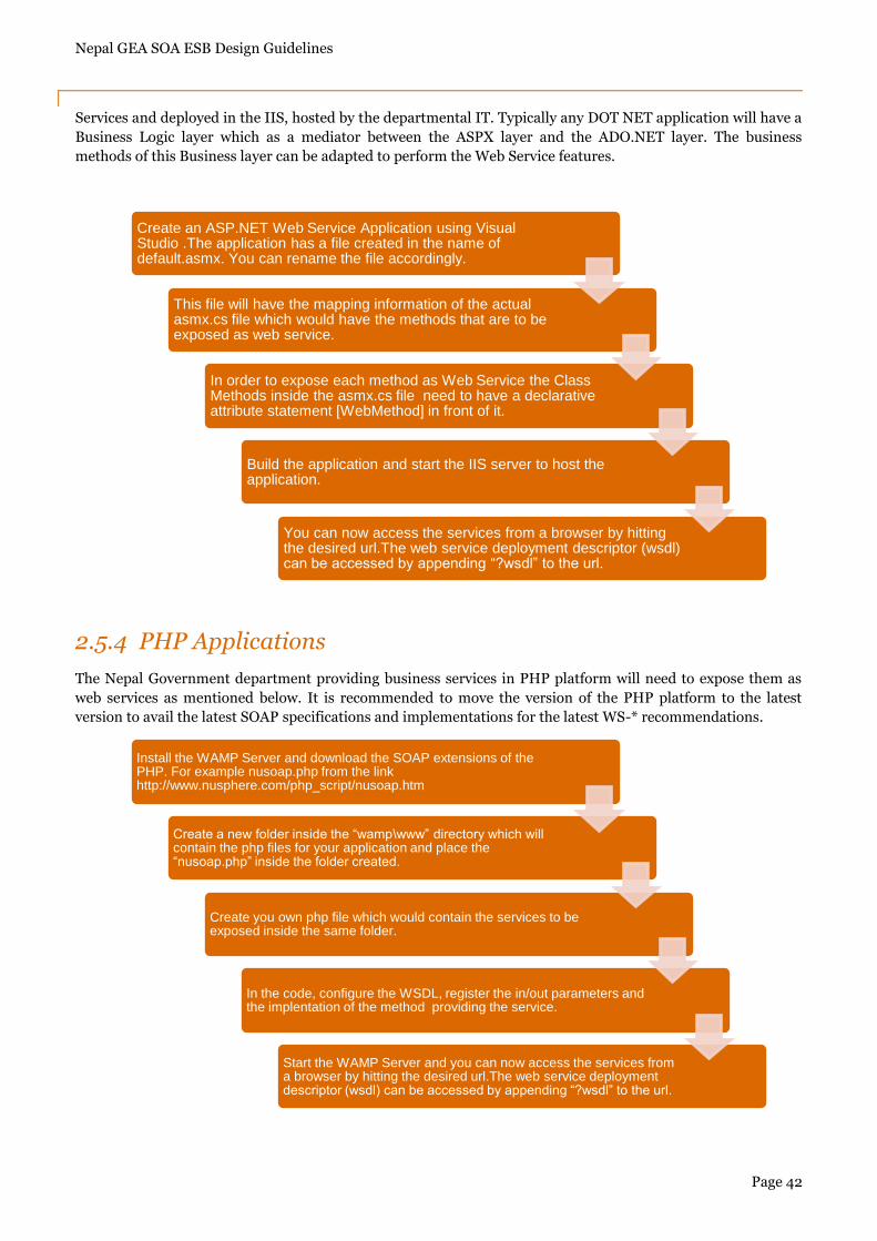
Nepal GEA SOA ESB Design Guidelines
Page 42
Services and deployed in the IIS, hosted by the departmental IT. Typically any DOT NET application will have a
Business Logic layer which as a mediator between the ASPX layer and the ADO.NET layer. The business
methods of this Business layer can be adapted to perform the Web Service features.
2.5.4 PHP Applications
The Nepal Government department providing business services in PHP platform will need to expose them as
web services as mentioned below. It is recommended to move the version of the PHP platform to the latest
version to avail the latest SOAP specifications and implementations for the latest WS-* recommendations.
Create an ASP.NET Web Service Application using Visual Studio .The application has a file created in the name of default.asmx. You can rename the file accordingly.
This file will have the mapping information of the actual asmx.cs file which would have the methods that are to be exposed as web service.
In order to expose each method as Web Service the Class Methods inside the asmx.cs file need to have a declarative attribute statement [WebMethod] in front of it.
Build the application and start the IIS server to host the application.
You can now access the services from a browser by hitting the desired url.The web service deployment descriptor (wsdl) can be accessed by appending “?wsdl” to the url.
Install the WAMP Server and download the SOAP extensions of the PHP. For example nusoap.php from the link http://www.nusphere.com/php_script/nusoap.htm
Create a new folder inside the “wamp\www” directory which will contain the php files for your application and place the “nusoap.php” inside the folder created.
Create you own php file which would contain the services to be exposed inside the same folder.
In the code, configure the WSDL, register the in/out parameters and the implentation of the method providing the service.
Start the WAMP Server and you can now access the services from a browser by hitting the desired url.The web service deployment descriptor (wsdl) can be accessed by appending “?wsdl” to the url.
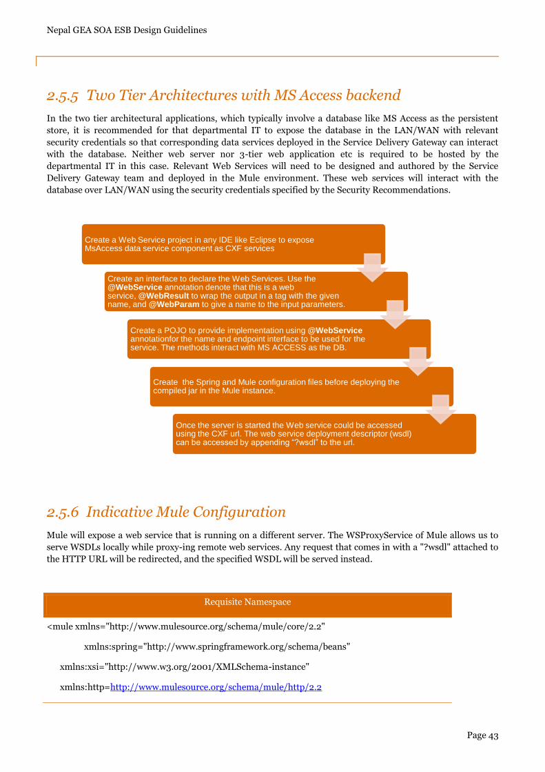
Nepal GEA SOA ESB Design Guidelines
Page 43
2.5.5 Two Tier Architectures with MS Access backend
In the two tier architectural applications, which typically involve a database like MS Access as the persistent
store, it is recommended for that departmental IT to expose the database in the LAN/WAN with relevant
security credentials so that corresponding data services deployed in the Service Delivery Gateway can interact
with the database. Neither web server nor 3-tier web application etc is required to be hosted by the
departmental IT in this case. Relevant Web Services will need to be designed and authored by the Service
Delivery Gateway team and deployed in the Mule environment. These web services will interact with the
database over LAN/WAN using the security credentials specified by the Security Recommendations.
2.5.6 Indicative Mule Configuration
Mule will expose a web service that is running on a different server. The WSProxyService of Mule allows us to
serve WSDLs locally while proxy-ing remote web services. Any request that comes in with a "?wsdl" attached to
the HTTP URL will be redirected, and the specified WSDL will be served instead.
Requisite Namespace
<mule xmlns="http://www.mulesource.org/schema/mule/core/2.2"
xmlns:spring="http://www.springframework.org/schema/beans"
xmlns:xsi="http://www.w3.org/2001/XMLSchema-instance"
xmlns:http=http://www.mulesource.org/schema/mule/http/2.2
Create a Web Service project in any IDE like Eclipse to expose MsAccess data service component as CXF services
Create an interface to declare the Web Services. Use the @WebService annotation denote that this is a web service, @WebResult to wrap the output in a tag with the given name, and @WebParam to give a name to the input parameters.
Create a POJO to provide implementation using @WebServiceannotationfor the name and endpoint interface to be used for the service. The methods interact with MS ACCESS as the DB.
Create the Spring and Mule configuration files before deploying the compiled jar in the Mule instance.
Once the server is started the Web service could be accessed using the CXF url. The web service deployment descriptor (wsdl) can be accessed by appending “?wsdl” to the url.
Nepal GEA SOA ESB Design Guidelines
Page 44
Requisite Namespace
Requisite Schema
< xsi:schemaLocation="
http://www.springframework.org/schema/beans
http://www.springframework.org/schema/beans/spring-beans-2.5.xsd
http://www.mulesource.org/schema/mule/http/2.2
http://www.mulesource.org/schema/mule/http/2.2/mule-http.xsd
http://www.mulesource.org/schema/mule/core/2.2
http://www.mulesource.org/schema/mule/core/2.2/mule.xsd">
Configuration
<service name="ProxyLicenseService">
<inbound>
<!-- WSDL URL: http://localhost:8888/stockquote.asmx?wsdl -->
<inbound-endpoint address="http://localhost:9999/proxyTelReg"
synchronous="true"/>
</inbound>
<outbound>
<chaining-router>
<outbound-endpoint
address="http://localhost:63821/LicenseService.asmx?wsdl" synchronous="true"/>
</chaining-router>
</outbound>
</service>
2.6 Guidelines on Service Contracts between Consumers and Producers
Service orientation places a great deal of emphasis on the design of service contracts between consumers and
producers. The Standardized Service Contract Design principle requires that all contracts within a given service
inventory conform to the same conventions so as to establish a truly federated endpoint layer.
2.6.1 Decoupled Contract
The guideline of Decoupled Contract answers to the following question – how can a service express its
capabilities independently of its implementation?
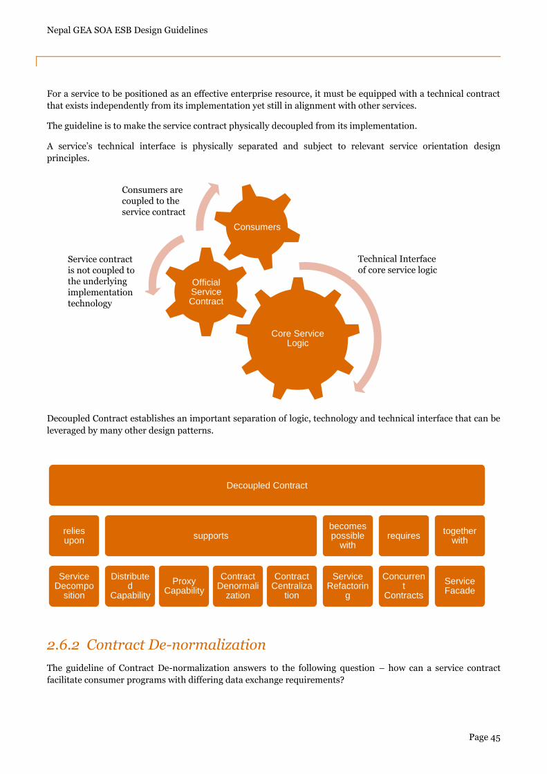
Nepal GEA SOA ESB Design Guidelines
Page 45
For a service to be positioned as an effective enterprise resource, it must be equipped with a technical contract
that exists independently from its implementation yet still in alignment with other services.
The guideline is to make the service contract physically decoupled from its implementation.
A service‟s technical interface is physically separated and subject to relevant service orientation design
principles.
Decoupled Contract establishes an important separation of logic, technology and technical interface that can be
leveraged by many other design patterns.
2.6.2 Contract De-normalization
The guideline of Contract De-normalization answers to the following question – how can a service contract
facilitate consumer programs with differing data exchange requirements?
Core Service Logic
Official Service Contract
Consumers
Decoupled Contract
relies upon
Service Decompo
sition
supports
Distributed
Capability
Proxy Capability
Contract Denormali
zation
Contract Centraliza
tion
becomes possible
with
Service Refactorin
g
requires
Concurrent
Contracts
together with
Service Facade
Technical Interface of core service logic
Service contract is not coupled to the underlying implementation technology
Consumers are coupled to the service contract
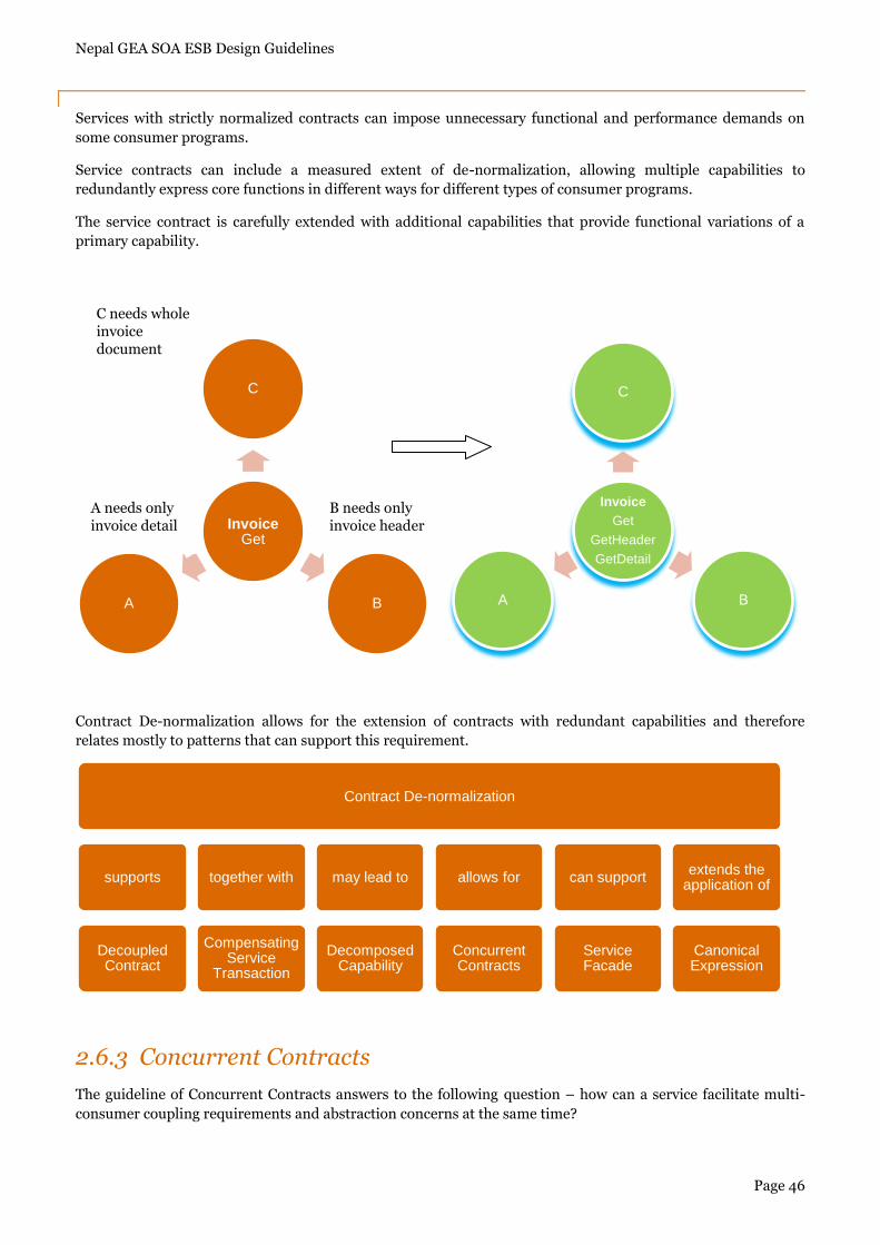
Nepal GEA SOA ESB Design Guidelines
Page 46
Services with strictly normalized contracts can impose unnecessary functional and performance demands on
some consumer programs.
Service contracts can include a measured extent of de-normalization, allowing multiple capabilities to
redundantly express core functions in different ways for different types of consumer programs.
The service contract is carefully extended with additional capabilities that provide functional variations of a
primary capability.
Contract De-normalization allows for the extension of contracts with redundant capabilities and therefore
relates mostly to patterns that can support this requirement.
2.6.3 Concurrent Contracts
The guideline of Concurrent Contracts answers to the following question – how can a service facilitate multi-
consumer coupling requirements and abstraction concerns at the same time?
InvoiceGet
C
BA
Invoice
Get
GetHeader
GetDetail
C
BA
Contract De-normalization
supports
Decoupled Contract
together with
Compensating Service
Transaction
may lead to
Decomposed Capability
allows for
Concurrent Contracts
can support
Service Facade
extends the application of
Canonical Expression
C needs whole invoice document
B needs only invoice header
A needs only invoice detail
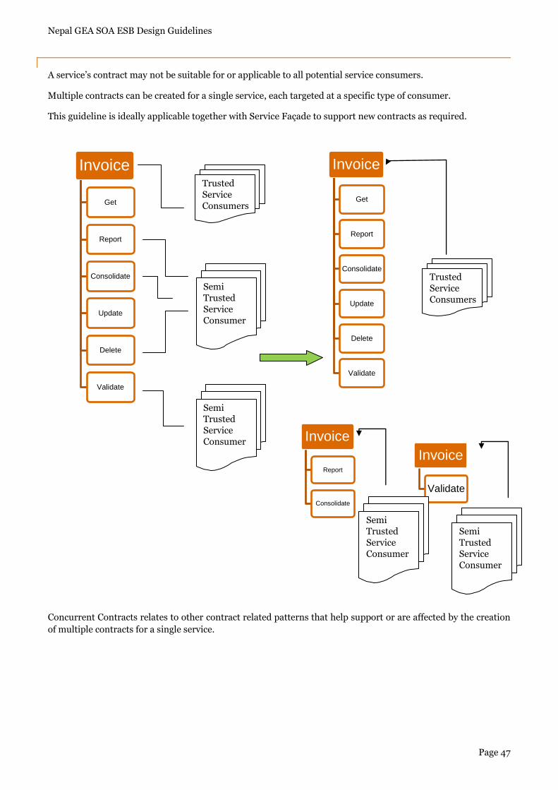
Nepal GEA SOA ESB Design Guidelines
Page 47
A service‟s contract may not be suitable for or applicable to all potential service consumers.
Multiple contracts can be created for a single service, each targeted at a specific type of consumer.
This guideline is ideally applicable together with Service Façade to support new contracts as required.
Concurrent Contracts relates to other contract related patterns that help support or are affected by the creation
of multiple contracts for a single service.
Invoice
Get
Report
Consolidate
Update
Delete
Validate
Invoice
Get
Report
Consolidate
Update
Delete
Validate
Invoice
Report
Consolidate
Invoice
Validate
Trusted Service Consumers
Semi Trusted Service Consumer
Semi Trusted Service Consumer
Trusted Service Consumers
Semi Trusted Service Consumer
Semi Trusted Service Consumer
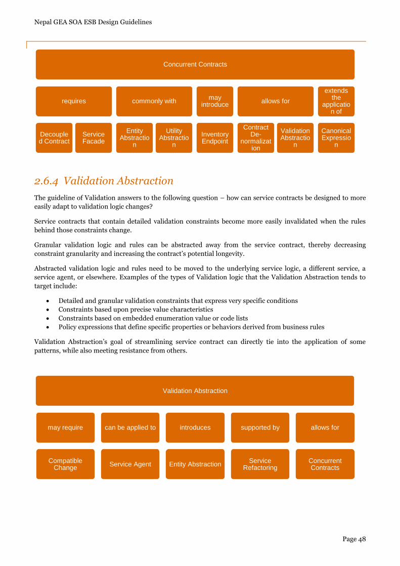
Nepal GEA SOA ESB Design Guidelines
Page 48
2.6.4 Validation Abstraction
The guideline of Validation answers to the following question – how can service contracts be designed to more
easily adapt to validation logic changes?
Service contracts that contain detailed validation constraints become more easily invalidated when the rules
behind those constraints change.
Granular validation logic and rules can be abstracted away from the service contract, thereby decreasing
constraint granularity and increasing the contract‟s potential longevity.
Abstracted validation logic and rules need to be moved to the underlying service logic, a different service, a
service agent, or elsewhere. Examples of the types of Validation logic that the Validation Abstraction tends to
target include:
Detailed and granular validation constraints that express very specific conditions
Constraints based upon precise value characteristics
Constraints based on embedded enumeration value or code lists
Policy expressions that define specific properties or behaviors derived from business rules
Validation Abstraction‟s goal of streamlining service contract can directly tie into the application of some
patterns, while also meeting resistance from others.
Concurrent Contracts
requires
Decoupled Contract
Service Facade
commonly with
Entity Abstractio
n
Utility Abstractio
n
may introduce
Inventory Endpoint
allows for
Contract De-
normalization
Validation Abstractio
n
extends the
application of
Canonical Expressio
n
Validation Abstraction
may require
Compatible Change
can be applied to
Service Agent
introduces
Entity Abstraction
supported by
Service Refactoring
allows for
Concurrent Contracts
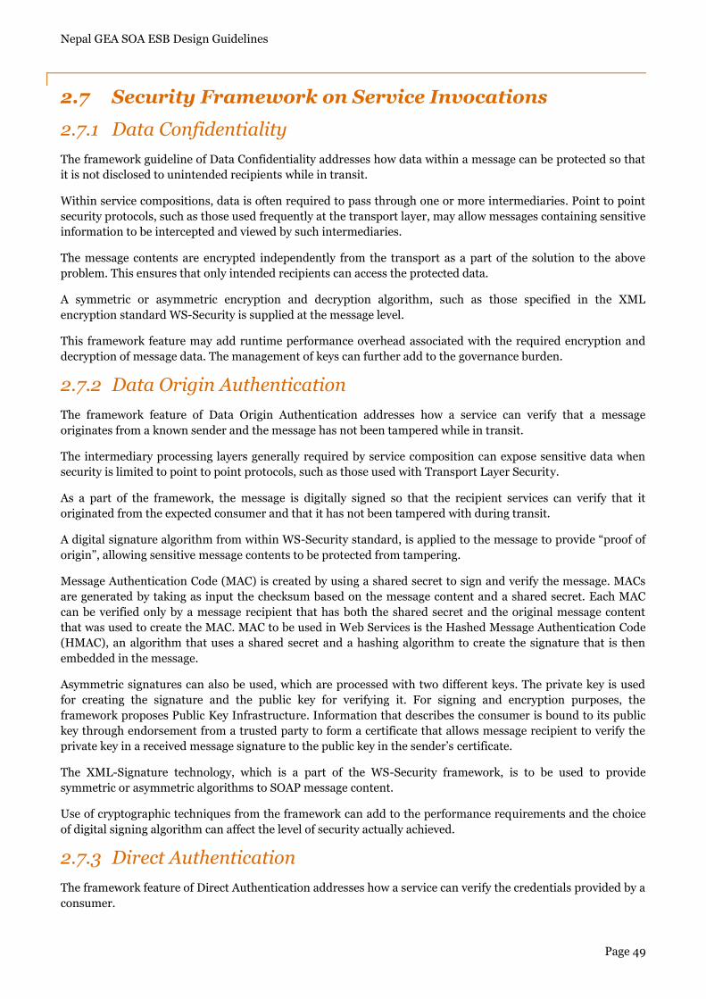
Nepal GEA SOA ESB Design Guidelines
Page 49
2.7 Security Framework on Service Invocations
2.7.1 Data Confidentiality
The framework guideline of Data Confidentiality addresses how data within a message can be protected so that
it is not disclosed to unintended recipients while in transit.
Within service compositions, data is often required to pass through one or more intermediaries. Point to point
security protocols, such as those used frequently at the transport layer, may allow messages containing sensitive
information to be intercepted and viewed by such intermediaries.
The message contents are encrypted independently from the transport as a part of the solution to the above
problem. This ensures that only intended recipients can access the protected data.
A symmetric or asymmetric encryption and decryption algorithm, such as those specified in the XML
encryption standard WS-Security is supplied at the message level.
This framework feature may add runtime performance overhead associated with the required encryption and
decryption of message data. The management of keys can further add to the governance burden.
2.7.2 Data Origin Authentication
The framework feature of Data Origin Authentication addresses how a service can verify that a message
originates from a known sender and the message has not been tampered while in transit.
The intermediary processing layers generally required by service composition can expose sensitive data when
security is limited to point to point protocols, such as those used with Transport Layer Security.
As a part of the framework, the message is digitally signed so that the recipient services can verify that it
originated from the expected consumer and that it has not been tampered with during transit.
A digital signature algorithm from within WS-Security standard, is applied to the message to provide “proof of
origin”, allowing sensitive message contents to be protected from tampering.
Message Authentication Code (MAC) is created by using a shared secret to sign and verify the message. MACs
are generated by taking as input the checksum based on the message content and a shared secret. Each MAC
can be verified only by a message recipient that has both the shared secret and the original message content
that was used to create the MAC. MAC to be used in Web Services is the Hashed Message Authentication Code
(HMAC), an algorithm that uses a shared secret and a hashing algorithm to create the signature that is then
embedded in the message.
Asymmetric signatures can also be used, which are processed with two different keys. The private key is used
for creating the signature and the public key for verifying it. For signing and encryption purposes, the
framework proposes Public Key Infrastructure. Information that describes the consumer is bound to its public
key through endorsement from a trusted party to form a certificate that allows message recipient to verify the
private key in a received message signature to the public key in the sender‟s certificate.
The XML-Signature technology, which is a part of the WS-Security framework, is to be used to provide
symmetric or asymmetric algorithms to SOAP message content.
Use of cryptographic techniques from the framework can add to the performance requirements and the choice
of digital signing algorithm can affect the level of security actually achieved.
2.7.3 Direct Authentication
The framework feature of Direct Authentication addresses how a service can verify the credentials provided by a
consumer.
Nepal GEA SOA ESB Design Guidelines
Page 50
Some of the capabilities offered by a service may be intended for specific groups of consumers or may involve
the transmission of sensitive data. Attackers that access this data could use it to compromise the service.
Service capabilities require that consumers provide credentials that can be authenticated against the identity
store of the enterprise. The service implementation is provided access to an identity store, allowing it to
authenticate the consumer directly. The data stores required by this framework feature can be centralized or
decentralized. The former model establishes a remote store that is shared by multiple services. A decentralized
model enables some or all services to own their own individual identity stores.
2.7.4 Brokered Authentication
The guideline of Brokered Authentication addresses how a service can efficiently verify consumer credentials if
the consumer and service do not trust each other or if the consumer requires access to multiple services.
The authentication broker with the centralized identity store assumes the responsibility for authenticating the
consumer and issuing a token that the consumer can use to access the service. The authentication broker
introduced into the inventory architecture carries out the intermediary authentication and issuance of
temporary credentials using X.509 Certificates or Kerberos, SAML tokens.