neo ATI 24V-N 119DU25 ver1 multi9 - Smith & Co. and use manuals issued with the automated system....
16
A3024N A5024N ATI SERIES English EN AUTOMATION FOR SWING GATES INSTALLATION MANUAL
Transcript of neo ATI 24V-N 119DU25 ver1 multi9 - Smith & Co. and use manuals issued with the automated system....

A3024N
A5024N
ATI S
ER
IES
English EN
AUTOMATION FOR SWING GATES
INSTALLATION MANUAL

WARNING!Important instructions for the safety of people:
READ CAREFULLY!Foreword
• Use of the products must be restricted to its intended use (i.e. that for which it was expressly built for). Any other use is to be considered dangerous. Came Cancelli Automatici S.p.A. is not liable for any damage resulting from improper, wrongful or unreasonable use • Keep these warnings with the installa-tion and use manuals issued with the automated system.
Before installing (preliminary check: in case of a negative outcome, do not proceed before having
complied with the safety obligations)• Make sure that the parts you intend to automate are in good working order, and that they are properly balanced and aligned. Also, make sure that proper mechanical stops are already in place • If the operator will be installed at a height of less than 2.5 m from the ground or other access level, check whether you will need any protections and/or warnings • Any gate leaves, fi tted with pedestrian entrances, onto which you will install an operator, must have a blocking mechanism when the gate is in motion • Make sure that the opening of the automated gate is not an entrapment hazard as regards any surrounding fi xed parts • Do not mount the operator upside down or onto any elements that may fold under its weight. If needed, add suitable reinforcements at the points where it is secured • Do not install onto gates on either an upward or downward slope (i.e. that are not on fl at, level ground) • Check that any lawn watering devices will not wet the gearmotor from the bottom up.
Installation• Carefully section off the entire site to prevent unauthorised access, especially by minors and children • Be careful when handling operators that weigh more than 20 Kg (see installa-tion manual). In such cases, employ proper weight handling safety equipment • All opening commands (e.g. buttons, key selectors, magnetic detectors, etc.) must be installed at least 1.85 m from the gate’s area of operation perimeter - or where they cannot be reached from the outside of the gate. Also, the direct commands (e.g. push button, or proximity devices, etc.) must be installed at a height of at least 1.5 m and must not be accessible to the public • All ‘maintained action’ com-mands, must be placed where the moving gate leaves, transit areas and driveways are completely visible • If missing, ap-ply a permanent label that shows the position of the release mechanism • Before delivering to the client, verify that the system is EN 12453 (impact test) standard compliant. Make sure that the operator has been properly adjusted and that the safety and protection devices, as well as the manual release
are working properly • Where necessary and in plain sight, apply the Warning Sings (e.g. gate plate).
Special instructions and advice for users
• Keep the gate’s area of operation clean and clear of any obstacles. Trim any vegetation that may interfere with the photocells • Do not allow children to play with the fi xed com-mand devices, or in the gate’s area of operation. Keep any remote control devices (i.e. transmitters) away from the chil-dren as well • Frequently check the system, to see whether any anomalies or signs of wear and tear appear on the moving parts, on the component parts, on the securing points, on the cables and any accessible connections. Keep any joints (i.e. hinges) lubricated and clean, and do the same where fric-tion may occur (i.e. slide rails) • Perform functional tests on photocells and sensitive edges, every six months. Keep glass panels constantly clean (use a slightly water-moistened cloth; do not use solvents or any other chemical products) • If the system requires repairs or modifi cations, release the operator and do not use it until safety conditions have been restored • Cut off the power supply before releasing the operator for manual openings. See instructions • Users are FORBIDDEN to carry out ANY ACTIONS THAT THEY HAVE NOT BEEN EXPRESSLY ASKED TO DO OR SO INDICATED in the manu-als. Any repairs, modifi cations to the settings and extraor-dinary maintenance MUST BE DONE BY THE TECHNICAL ASSISTANCE STAFF • On the periodic maintenance log, note down the checks you have done.
Special instructions and advice for all
• Avoid working near the hinges or moving mechanical parts • Stay clear of the gate’s area of operation when in motion • Do not resist the direction of movement of the gate; this may present a safety hazard • At all times be extremely careful about dangerous points that must be indicated by proper pictograms and/or black and yellow stripes • When using a selector or command in ‘maintained action’ mode, keep checking that there are no people in the area of operation of the moving parts. Do this until you release the command • The gate may move at any time without warning • Always cut the power when cleaning performing maintenance.

THIS PAGE LEFT INTENTIONALLY BLANKTHIS PAGE LEFT INTENTIONALLY BLANK

Pag
. 2
-
Man
ual
cod
e: 1
19
DU
25
119
DU
25
ver
. 1
.01
.0 01/
2011
©
CA
ME
cance
lli a
utom
atic
i s.p
.a.
- Th
e dat
a an
d in
form
atio
n re
por
ted
in t
his
inst
alla
tion
man
ual
are
susc
eptib
le t
o ch
ange
at a
ny t
ime
and
with
out
oblig
atio
n on
CA
ME
cance
lli a
utom
atic
i s.p
.a.
to n
otify
use
rs.
EN
GLIS
H
Control board power supply: 230 A.C. 50/60HzMotor power supply: 24V D.C. 50/60HzMax draw.: 10A Power: 120WOpening time (90°): adjustable
Gear ratio: 1/36Duty Cycle: Intensive useProtection Rating: IP44Weight:
A3024N = 10 kgA5024N = 11 kg
Gearmotor
This product is engineered and manufactured by CAME CANCELLI AUTOMATICI S.p.A. and complies with current safety regula-tions.
The gearmotor is composed of two, cast aluminium half shells inside of which rest the gearmotor and endstops – with electro blo-cking – and an endless screw, epicycloidal gear reduction system.
Description
Intended use
Legend of symbols
This symbol tells you to read the section with particular care.
This symbol tells you that the sections concern safety issues.
This symbol tells you what to say to the end-users.
Intended use and restrictions
The ATI 24V N gearmotor is specifi cally engineered to automate residential and condominium swing gates, even under intensive use.
Any use, other than that described above or installations performed in ways other than those described herein, are forbidden.
Reference Standards
“IMPORTANT INSTALLATION, SAFETY INSTRUCTIONS”
“CAUTION: IMPROPER INSTALLATION MAY CAUSE SERIOUS DAMAGE, FOLLOW ALL INSTALLATION INSTRUCTIONS CAREFULLY”
“THIS MANUAL IS ONLY FOR PROFESSIONAL OR QUALIFIED INSTALLERS”
Restrictions
Technical features
The company: Came Cancelli Automatici is ISO 9001 quality certified; is has also obtained the ISO 14001 environmental safe-guarding certification. Came engineers and manufactures all of its products in Italy.This product complies with the following standards: see declaration of compliance.
Gate leaf width
m
Gate leaf weightkg
A3024N A5024N
2.00 800 1000
2.50 600 800
3.00 400 600
4.00 / 500
5.00 / 400

A3024N
A5024N
12
3
4
5
5
Pag
. 3
-
Man
ual
cod
e: 1
19
DU
25
119
DU
25
ver
. 1
.01
.0 01/
2011
©
CA
ME
cance
lli a
utom
atic
i s.p
.a.
- Th
e dat
a an
d in
form
atio
n re
por
ted
in t
his
inst
alla
tion
man
ual
are
susc
eptib
le t
o ch
ange
at a
ny t
ime
and
with
out
oblig
atio
n on
CA
ME
cance
lli a
utom
atic
i s.p
.a.
to n
otify
use
rs.
EN
GLIS
H
Description of parts
4.4 Overall dimensions
Before installing, do the following:
• make sure the structure of the gate is sturdy, the hinges work and that there is no friction between moving parts and non-moving parts;
• measurement C cannot be greater than the value shown in Tab. 3, p. 5. In this case you need to work on the pillar until said measu-rement is obtained;
• the path of the electrical cables must comply with the command and safety instructions;
• there must be a soundly secured to the ground mechanical stop to prevent the gate leaf/gearmotor from over extending.
• Any connections inside the case (that provide continuance to the protective circuit) must be fitted with extra insulation as compared to the other conductive part inside;
• Make sure you have suitable tubing and conduits for the electrical cables to pass through and be protected against mechanical damage.
5.1 Preliminary checks
Travel
Travel
Pillar
Gate leafEnd stop
Hinge
1) Gearmotor2) Front bracket3) Back swivel-joint4) Back bracket5) Anchoring plate
5 Installation

1
1
2 3 4 4 5
4 4
67
8
Pag
. 4
-
Man
ual
cod
e: 1
19
DU
25
119
DU
25
ver
. 1
.01
.0 01/
2011
©
CA
ME
cance
lli a
utom
atic
i s.p
.a.
- Th
e dat
a an
d in
form
atio
n re
por
ted
in t
his
inst
alla
tion
man
ual
are
susc
eptib
le t
o ch
ange
at a
ny t
ime
and
with
out
oblig
atio
n on
CA
ME
cance
lli a
utom
atic
i s.p
.a.
to n
otify
use
rs.
EN
GLIS
H
Tools and materials
Make sure you have all the tools and materials you will need for the installation at hand to work in total safety and compliance with the current standards and regulations. The following figure illustrates the minimum equipment needed by the installer.
N.B.: If the cable length differs from that specifi ed in the table, then you must determine the proper cable diameter in the basis of the actual power draw by the connected devices and depending on the standards specifi ed in CEI EN 60204-1.For connections that require several, sequential loads, the sizes given on the table must be re-evaluated based on actual power draw and distances.
Cable list and minimum thickness
1) Operator2) Control panel3) Radio receiver4) Photocells
Standard installation
5) Selector switch6) Antenna7) Flashing light8) Transmitter
Connections Type of cable Length of cable1 < 10 m
Length of cable10 < 20 m
Length of cable20 < 30 m
Control panel power supply 230V
FROR CEI 20-22
CEI EN 50267-2-1
3G x 1,5 mm2 3G x 2,5 mm2 3G x 4 mm2
Flashing light 24V 3 x 1 mm2 3 x 1,5 mm2 3 x 2,5 mm2
Photocell transmitters 2 x 0,5 mm2 2 x 1 mm2 2 x 1,5 mm2
Photocell receivers 2 x 0,5 mm2 2 x 0.5 mm2 2 x 0,5 mm2
24V Accessories power supply 4 x 0,5 mm2 4 x 0,5 mm2 4 x 0,5 mm2
Command buttons 2 x 0,5 mm2 2 x 0,5 mm2 2 x 1 mm2
Endstop 2 x 0,5 mm2 2 x 0,5 mm2 2 x 0,5 mm2
Encoder plug 3 x 0,5 mm2 3 x 1 mm2 3 x 1,5 mm2
Antenna connection RG58 max. 50 m
Tab. 3
Pag
. 5
-
Man
ual
cod
e: 1
19
DU
25
119
DU
25
ver
. 1
.01
.0 01/
2011
©
CA
ME
cance
lli a
utom
atic
i s.p
.a.
- Th
e dat
a an
d in
form
atio
n re
por
ted
in t
his
inst
alla
tion
man
ual
are
susc
eptib
le t
o ch
ange
at a
ny t
ime
and
with
out
oblig
atio
n on
CA
ME
cance
lli a
utom
atic
i s.p
.a.
to n
otify
use
rs.
EN
GLIS
H
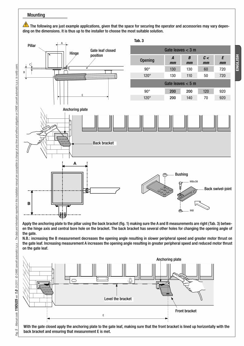
The following are just example applications, given that the space for securing the operator and accessories may vary depen-ding on the dimensions. It is thus up to the installer to choose the most suitable solution.
Mounting
Apply the anchoring plate to the pillar using the back bracket (fig. 1) making sure the A and B measurements are right (Tab. 3) betwe-en the hinge axis and central bore hole on the bracket. The back bracket has several other holes for changing the opening angle of the gate.N.B.: increasing the B measurement decreases the opening angle resulting in slower peripheral speed and greater motor thrust on the gate leaf. Increasing measurement A increases the opening angle resulting in greater peripheral speed and reduced motor thrust on the gate leaf.
With the gate closed apply the anchoring plate to the gate leaf, making sure that the front bracket is lined up horizontally with the back bracket and ensuring that measurement E is met.
Pillar
HingeGate leaf closed position
Anchoring plate
Back bracket
Bushing
Back swivel-joint
Level the bracket
Anchoring plate
Front bracket
Gate leaves < 3 m
Opening Amm
Bmm
C <mm
Emm
90° 130 130 60 720
120° 130 110 50 720
Gate leaves < 5 m
90° 200 200 120 920
120° 200 140 70 920
M8x10
M8x50
CAME
180
Pag
. 6
-
Man
ual
cod
e: 1
19
DU
25
119
DU
25
ver
. 1
.01
.0 01/
2011
©
CA
ME
cance
lli a
utom
atic
i s.p
.a.
- Th
e dat
a an
d in
form
atio
n re
por
ted
in t
his
inst
alla
tion
man
ual
are
susc
eptib
le t
o ch
ange
at a
ny t
ime
and
with
out
oblig
atio
n on
CA
ME
cance
lli a
utom
atic
i s.p
.a.
to n
otify
use
rs.
EN
GLIS
H
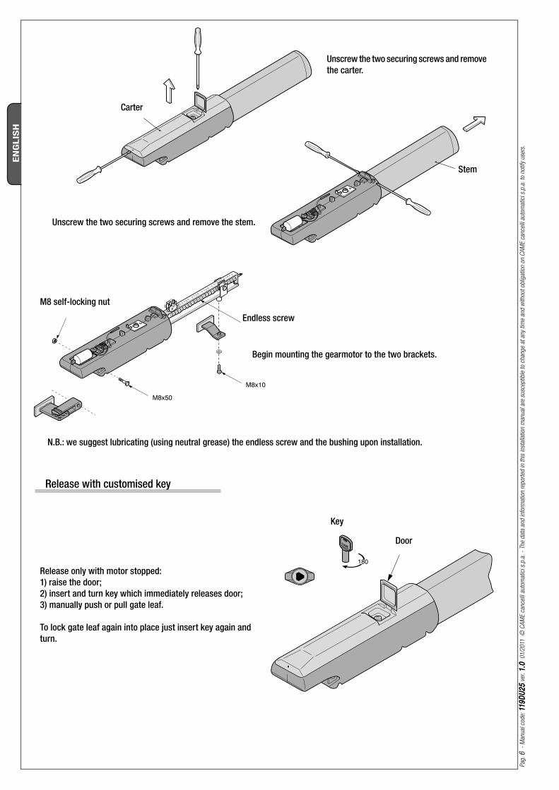
Unscrew the two securing screws and remove the carter.
Unscrew the two securing screws and remove the stem.
N.B.: we suggest lubricating (using neutral grease) the endless screw and the bushing upon installation.
Begin mounting the gearmotor to the two brackets.
M8 self-locking nut
Endless screw
Carter
Stem
Release only with motor stopped:1) raise the door;2) insert and turn key which immediately releases door;3) manually push or pull gate leaf.
To lock gate leaf again into place just insert key again and turn.
Release with customised key
Key
Door

Pag
. 7
-
Man
ual
cod
e: 1
19
DU
25
119
DU
25
ver
. 1
.01
.0 01/
2011
©
CA
ME
cance
lli a
utom
atic
i s.p
.a.
- Th
e dat
a an
d in
form
atio
n re
por
ted
in t
his
inst
alla
tion
man
ual
are
susc
eptib
le t
o ch
ange
at a
ny t
ime
and
with
out
oblig
atio
n on
CA
ME
cance
lli a
utom
atic
i s.p
.a.
to n
otify
use
rs.
EN
GLIS
H
Securing and adjusting the endstop
Spindle
Endless screw
Closing-speed brake microswitch
Microswitch bar
Spindle
Cable support Microswitch actuating sledStop brake microswitch
OPENING PHASE (deceleration if set up on the control panel):
Release the gearmotor and swing the gate-leaf to the fully open position you desire, then, unscrew the securing screws on the opening stop micro-switches assembly.
Slide the micro-switch assembly along the micro-switch bar until it is completely passing the contact point on the micro-switch activating sled (as shown in part B.).
Secure the micro-switch assembly using the respective screws.
OPENING PHASE: (stop)
Release the gearmotor and swing the gate-leaf to the fully open position you desire, then, unscrew the securing screws on the opening stop micro-switches assembly.
Slide the micro-switch assembly along the micro-switch bar until it is inserted by contact on the micro-switch activating sled
Secure the micro-switch assembly using the respective screws.
CLOSING PHASE (deceleration)
Swing the gate until fully closed.
Unscrew the securing screws on the closing decelaration micro-switch assembly.
Slide the micro-switch assembly along the micro-switch bar until it is completely passing the contact point on the micro-switch activating sled (as shown in part A.)
Secure the micro-switch assembly using the respective screws.
Part. A.
Excluding the micro-switch contact (fully closed gate-leaf)Micro-switch
insertion area
Part. B.
Excluding the micro-switch contact (fully open gate-leaf)
Deceleration micro-switch insertion area

ZL180
ZL180
M1M2
Pag
. 8
-
Man
ual
cod
e: 1
19
DU
25
119
DU
25
ver
. 1
.01
.0 01/
2011
©
CA
ME
cance
lli a
utom
atic
i s.p
.a.
- Th
e dat
a an
d in
form
atio
n re
por
ted
in t
his
inst
alla
tion
man
ual
are
susc
eptib
le t
o ch
ange
at a
ny t
ime
and
with
out
oblig
atio
n on
CA
ME
cance
lli a
utom
atic
i s.p
.a.
to n
otify
use
rs.
EN
GLIS
H
Connecting to the ZL180 control panel
Connecting 2 motors
Connecting 1 motor

ZL180
M1M2
A
B
E
Amm
Bmm
Emm
A3024N 130 130 720
A5024N 200 200 920
Pag
. 9
-
Man
ual
cod
e: 1
19
DU
25
119
DU
25
ver
. 1
.01
.0 01/
2011
©
CA
ME
cance
lli a
utom
atic
i s.p
.a.
- Th
e dat
a an
d in
form
atio
n re
por
ted
in t
his
inst
alla
tion
man
ual
are
susc
eptib
le t
o ch
ange
at a
ny t
ime
and
with
out
oblig
atio
n on
CA
ME
cance
lli a
utom
atic
i s.p
.a.
to n
otify
use
rs.
EN
GLIS
H
- Measure values A and B (Tab. 4)
- Secure the tail bracket to an extra bracket and apply to post.
- Open gate (max 90°), measure value E (Tab. 4) and secure head bracket to gate leaf.
- Perform electrical connections;
- Reposition and adjust openin stop microswitch.
Application for outward opening
Outward
Inward
Extra bracket
Tab. 4

Pag
. 1010
-
Man
ual
cod
e: 1
19
DU
25
119
DU
25
ver
. 1
.01
.0 01/
2011
©
CA
ME
cance
lli a
utom
atic
i s.p
.a.
- Th
e dat
a an
d in
form
atio
n re
por
ted
in t
his
inst
alla
tion
man
ual
are
susc
eptib
le t
o ch
ange
at a
ny t
ime
and
with
out
oblig
atio
n on
CA
ME
cance
lli a
utom
atic
i s.p
.a.
to n
otify
use
rs.
EN
GLIS
H
Safety instructions
This product must only be employed for its originally intended use. Any other use is wrong and potentially dangerous. The manufacturer cannot be held liable for any damages resulting from wrongful, erroneous or negligent uses.Avoid working close to the hinges or other moving mechanical parts. Stay out of the opening/closing arc when operator is in motion.Do not exercise force against the motion of the operator as this could result in potentially dangerous situations.
Important safety instructions
Danger of crushing hands
Danger of crushing feet
Danger! High voltage
No transit during operation
Do not allow children to play or loiter within the opening/closing arc of the operator. Keep transmiters and any other command device out the reach of children, to prevent operator from being activated by accident.In the event of anomalous behaviour, stop using the operator immediately.

Pag
. 1111
-
Man
ual
cod
e: 1
19
DU
25
119
DU
25
ver
. 1
.01
.0 01/
2011
©
CA
ME
cance
lli a
utom
atic
i s.p
.a.
- Th
e dat
a an
d in
form
atio
n re
por
ted
in t
his
inst
alla
tion
man
ual
are
susc
eptib
le t
o ch
ange
at a
ny t
ime
and
with
out
oblig
atio
n on
CA
ME
cance
lli a
utom
atic
i s.p
.a.
to n
otify
use
rs.
EN
GLIS
H
Maintenance
Periodic maintenance
Periodic maintenance to be carried out by the end-user is as follows: wipe clean the glass surface of the photocells; check that the safety devices work properly; remove any obstructions.We suggest checking the state of lubrication and tightness of the anchoring screws on the operator.To check the efficiency of the safety devices, move an object in front of the photocells when gate is closing. If the operator inverts the motion or stops, the photocells are working properly.This is the only maintenance procedure to be carried out with the power source connected.Before performing any maintenance procedures, cut off the main power, to prevent possible accidents due to gate movement.To clean the photocells use a water dampened cloth. Do not use solvents or other chemical products which may ruin the devices.In the event of any strange vibrations or squeaking, lubricate the joints with grease, as shown in the diagram. Make sure there are no plants within the photocell’s beam, and that the gate motion is free of any obstacles.
MALFUNCTIONS POSSIBLE CAUSES CHECK AND REMEDIES
The gate will not open nor close
• There is no power• The gearmotor is released• The transmitter’s batteries are run down• The transmitter is broken• The stop button is either stuck or broken• The opening/closing button or the keyswitch are stuck
• Check that the power is up• Lock gearmotor (Chapt. 5.6)• Replace batteries• Call assistance• Call assistance• Call assistance
The gate opens but will not close
• The photocells are engaged • Check that photocells are cle-an and in good working order• Call assistance
The flashing light does not work
• The bulb is burnt • Call assistance
Trouble shooting

Pag
. 1212
-
Man
ual
cod
e: 1
19
DU
25
119
DU
25
ver
. 1
.01
.0 01/
2011
©
CA
ME
cance
lli a
utom
atic
i s.p
.a.
- Th
e dat
a an
d in
form
atio
n re
por
ted
in t
his
inst
alla
tion
man
ual
are
susc
eptib
le t
o ch
ange
at a
ny t
ime
and
with
out
oblig
atio
n on
CA
ME
cance
lli a
utom
atic
i s.p
.a.
to n
otify
use
rs.
EN
GLIS
H
7.3 Extra-ordinary maintenance
The following table serves to note down any extraordinary maintenance, repairs or improvements performed by specialised firms.N.B.: Any extraordinary maintenance must be performed by specialised technicians.
Extra-ordinary maintenance log
Periodic maintenance log for end-user (every 6 moths)
Date Notes Signature
Installer’s stamp Operator name
Date of job
Technician’s signature
Requester’s signature
Job performed ___________________________________________________________________________________________________________________________________________________________________________________________________________________________________________________________________________________________

Pag
. 1
31
3
- M
anual
cod
e: 1
19
DU
25
119
DU
25
ver
. 1
.01
.0 01/
2011
©
CA
ME
cance
lli a
utom
atic
i s.p
.a.
- Th
e dat
a an
d in
form
atio
n re
por
ted
in t
his
inst
alla
tion
man
ual
are
susc
eptib
le t
o ch
ange
at a
ny t
ime
and
with
out
oblig
atio
n on
CA
ME
cance
lli a
utom
atic
i s.p
.a.
to n
otify
use
rs.
EN
GLIS
H
MANUFACTURER’S DECLARATION OF CONFORMITYPursuant to annex II B of the Machinery Directive 98/37/EC
CAME Cancelli Automatici S.p.A.
via Martiri della Libertà, 15 31030 Dosson di Casier - Treviso - ITALY tel (+39) 0422 4940 - fax (+39) 0422 4941 internet: www.came.it - e-mail: [email protected]
Declares under its own responsibility that the equipments for automatic garage doors and gates listed below :
A3024N / A5024N
… comply with the National Law related to the following European Directives and to the applicable parts of the following Standards.
--- DIRECTIVES ---98/37/CE - 98/79/CE MACHINERY DIRECTIVE
98/336/CEE - 92/31/CEE ELECTROMAGNETIC COMPATIBILITY DIRECTIVE
73/23/CEE - 93/68/CE LOW VOLTAGE DIRECTIVE
89/106/CEE CONSTRUCTION PRODUCTS DIRECTIVE
--- STANDARDS ---EN 13241-1 EN 12635 EN 61000-6-2 EN 12453 EN 12978 EN 61000-6-3 EN 12445 EN 60335-1
IMPORTANT WARNING!
Do not use the equipment specifi ed here above, before completing the full installation in full compliance
with the Machinery Directive 98/37/EC
Conformity declaration
Reference code to request a true copy of the original: DDF B EN A001C
MANAGING DIRECTORMr . Andrea Menuzzo
Phasing out and disposal
CAME CANCELLI AUTOMATICI S.p.A. employs a UNI EN ISO 14001 certified and compliant environmental protection system at its plants, to ensure that environmental safeguarding.We ask you to keep protecting the environment, as CAME deems it to be one of the fundamental points of its market operations strategies, by simply following these brief guidelines when disposing:
DISPOSING THE PACKING MATERIALSThe packing components (cardboard, plastic, etc.) are solid urban waste and may be disposed of without any particular difficulty, by simply separating them so that they can be recycled.Before actions it is always advisable to check the pertinent legislation where installation will take place.DO NOT DISPOSE OF IN NATURE!
DISPOSING OF THE PRODUCTOur products are made using different types of materials. The majority of them (aluminium, plastic, iron, electric cables) can be considered to be solid urban waste. They may be recycled at authorised firms. Other components (electrical circuit board, remote control batteries etc.) may contain hazardous waste. They must, thus, be removed and turned in to licensed firms for their disposal.Before acting always check the local laws on the matter.DO NOT DISPOSE OF IN NATURE!
Installer’s stamp Operator name
Date of job
Technician’s signature
Requester’s signature
Job performed ___________________________________________________________________________________________________________________________________________________________________________________________________________________________________________________________________________________________

CAMECAME FranceFrance S.a. S.a. FRANCE7, Rue Des HarasZ.i. Des Hautes Patures92737 Nanterre CedexNanterre Cedex
(+33) 0 825 825 874 (+33) 1 46 13 05 00
GERMANY CAME Gmbh Seefeld CAME Gmbh SeefeldAkazienstrasse, 9
16356 Seefeld Seefeld Bei Berlin (+49) 33 3988390
(+49) 33 39883985
CAME Automatismes S.a. CAME Automatismes S.a. FRANCE3, Rue Odette Jasse13015 MarseilleMarseille
(+33) 0 825 825 874 (+33) 4 91 60 69 05
U.A.E. CAME Gulf Fze CAME Gulf FzeOffi ce No: S10122a2o210
P.O. Box 262853 Jebel Ali Free Zone - Dubai Dubai
(+971) 4 8860046 (+971) 4 8860048
CAME Automatismos S.a. CAME Automatismos S.a. SPAINC/juan De Mariana, N. 17-local28045 Madrid Madrid
(+34) 91 52 85 009 (+34) 91 46 85 442
RUSSIA CAME Rus CAME RusUmc Rus LlcUmc Rus Llc
Ul. Otradnaya D. 2b, Str. 2, offi ce 219 127273, MoscowMoscow
(+7) 495 739 00 69 (+7) 495 739 00 69 (ext. 226)
CAME United Kingdom Ltd. CAME United Kingdom Ltd. GREAT BRITAINUnit 3 Orchard Business ParkTown Street, SandiacreNottingham Nottingham - Ng10 5bp
(+44) 115 9210430 (+44) 115 9210431
PORTUGAL CAME Portugal CAME Portugal Ucj Portugal Unipessoal LdaUcj Portugal Unipessoal Lda
Rua Liebig, nº 23 2830-141 BarreiroBarreiro
(+351) 21 207 39 67 (+351) 21 207 39 65
CAME Group Benelux S.a. CAME Group Benelux S.a. BELGIUMZoning Ouest 77860 Lessines Lessines
(+32) 68 333014 (+32) 68 338019
INDIA CAME India CAME India Automation Solutions Pvt. LtdAutomation Solutions Pvt. Ltd
A - 10, Green Park 110016 - New DelhiNew Delhi
(+91) 11 64640255/256 (+91) 2678 3510
CAME Americas Automation Llc CAME Americas Automation Llc U.S.A11345 NW 122nd St. MedleyMedley, FL 33178
(+1) 305 433 3307 (+1) 305 396 3331
ASIA CAME Asia Pacific CAME Asia Pacific 60 Alexandra Terrace #09-09
Block C, The ComTech118 502 SingaporeSingapore
(+65) 6275 8426 (+65) 6275 5451
CAME Gmbh CAME Gmbh GERMANYKornwestheimer Str. 3770825 Korntal Korntal Munchingen Bei Stuttgart
(+49) 71 5037830 (+49) 71 50378383
CAME Cancelli Automatici S.p.a. CAME Cancelli Automatici S.p.a. ITALYVia Martiri Della Libertà, 1531030 Dosson Di Casier Dosson Di Casier (Tv)
(+39) 0422 4940 (+39) 0422 4941
Informazioni Commerciali 800 848095
ITALY CAME Sud s.r.l.CAME Sud s.r.l.Via F. Imparato, 198
Centro Mercato 2, Lotto A/7 80146 Napoli Napoli
(+39) 081 7524455 (+39) 081 7529190
CAME Service Italia S.r.l. CAME Service Italia S.r.l. ITALYVia Della Pace, 2831030 Dosson Di Casier Dosson Di Casier (Tv)
(+39) 0422 383532 (+39) 0422 490044
Assistenza Tecnica 800 295830Assistenza Tecnica 800 295830
ITALY CAME Global Utilities s.r.l.CAME Global Utilities s.r.l.Via E. Fermi, 31
20060 GessateGessate (Mi) (+39) 02 95380366 (+39) 02 95380224
01_2011
www.came.com www.came.it
En
glish
En
glish
-
Man
ual
cod
e: 1
19
DU
25
119
DU
25
ver
. 1
.01
.0 01/
2011
© C
AM
E ca
nce
lli a
utom
atic
i s.p
.a.
The
dat
a an
d in
form
atio
n re
por
ted
in t
his
inst
alla
tion
man
ual
are
susc
eptib
le t
o ch
ange
at a
ny t
ime
and
with
out
oblig
atio
n on
CA
ME
cance
lli a
utom
atic
i s.p
.a.
to n
otify
use
rs.