Nematic Liquid Crystal Droplets Forced with Static and ...
13
crystals Article Stable and Metastable Patterns in Chromonic Nematic Liquid Crystal Droplets Forced with Static and Dynamic Magnetic Fields Jordi Ignés-Mullol 1,2, * , Marc Mora 1,2,† , Berta Martínez-Prat 1,2 , Ignasi Vélez-Cerón 1,2 , R. Santiago Herrera 1,2 and Francesc Sagués 1,2 1 Departament de Ciència de Materials i Química Física, Universitat de Barcelona, 08028 Barcelona, Spain; [email protected] (M.M.); [email protected] (B.M.-P.); [email protected] (I.V.-C.); [email protected] (R.S.H.); [email protected] (F.S.) 2 Institute of Nanoscience and Nanotechnology of the University of Barcelona (IN2UB), 08028 Barcelona, Spain * Correspondence: [email protected]; Tel.: +34-934-039-237 † Current address: Department of Physics and Randall Centre for Cell and Molecular Biophysics, King’s College London, London, WC2R 2LS, UK. Received: 30 December 2019; Accepted: 14 February 2020; Published: 24 February 2020 Abstract: Spherical confinement of nematic liquid crystals leads to the formation of equilibrium director field configurations that include point and line defects. Driving these materials with flows or dynamic fields often results in the formation of alternative metastable states. In this article, we study the effect of magnetic field alignment, both under static and dynamic conditions, of nematic gems (nematic droplets in coexistence with the isotropic phase) and emulsified nematic droplets of a lyotropic chromonic liquid crystal. We use a custom polarizing optical microscopy assembly that incorporates a permanent magnet whose strength and orientation can be dynamically changed. By comparing simulated optical patterns with microscopy images, we measure an equilibrium twisted bipolar pattern within nematic gems that is only marginally different from the one reported for emulsified droplets. Both systems evolve to concentric configurations upon application of a static magnetic field, but behave very differently when the field is rotated. While the concentric texture within the emulsified droplets is preserved and only displays asynchronous oscillations for high rotating speeds, the nematic gems transform into a metastable untwisted bipolar configuration that is memorized by the system when the field is removed. Our results demonstrate the importance of boundary conditions in determining the dynamic behavior of confined liquid crystals even for configurations that share similar equilibrium bulk structures. Keywords: liquid crystals; lyotropic; chromonic; defects; confinement effects; emulsions 1. Introduction Liquid crystals are anisotropic liquids that feature long-range orientational order, locally characterized by a director field, whose distortion from uniform alignment incurs in an elastic free-energy cost [1,2]. Spatial confinement of these materials often triggers the formation of patterns and complex defect configurations of the director, as a result of the interplay between the drive towards free-energy minimization and the topology imposed by boundary conditions on the enclosing container walls [3]. The presence of topological defects is often a hindrance to be avoided in LC-based applications, such as displays and electro-optical devices but, in recent years, the induction and control of defects has been recognized as an opportunity for the development of novel functional materials [4,5], often in combination with dispersed particles that organize the Crystals 2020, 10, 138; doi:10.3390/cryst10020138 www.mdpi.com/journal/crystals
Transcript of Nematic Liquid Crystal Droplets Forced with Static and ...

crystals
Article
Stable and Metastable Patterns in ChromonicNematic Liquid Crystal Droplets Forced with Staticand Dynamic Magnetic Fields
Jordi Ignés-Mullol 1,2,* , Marc Mora 1,2,†, Berta Martínez-Prat 1,2, Ignasi Vélez-Cerón 1,2,R. Santiago Herrera 1,2 and Francesc Sagués 1,2
1 Departament de Ciència de Materials i Química Física, Universitat de Barcelona, 08028 Barcelona, Spain;[email protected] (M.M.); [email protected] (B.M.-P.); [email protected] (I.V.-C.);[email protected] (R.S.H.); [email protected] (F.S.)
2 Institute of Nanoscience and Nanotechnology of the University of Barcelona (IN2UB),08028 Barcelona, Spain
* Correspondence: [email protected]; Tel.: +34-934-039-237† Current address: Department of Physics and Randall Centre for Cell and Molecular Biophysics,
King’s College London, London, WC2R 2LS, UK.
Received: 30 December 2019; Accepted: 14 February 2020; Published: 24 February 2020�����������������
Abstract: Spherical confinement of nematic liquid crystals leads to the formation of equilibriumdirector field configurations that include point and line defects. Driving these materials with flowsor dynamic fields often results in the formation of alternative metastable states. In this article,we study the effect of magnetic field alignment, both under static and dynamic conditions, of nematicgems (nematic droplets in coexistence with the isotropic phase) and emulsified nematic dropletsof a lyotropic chromonic liquid crystal. We use a custom polarizing optical microscopy assemblythat incorporates a permanent magnet whose strength and orientation can be dynamically changed.By comparing simulated optical patterns with microscopy images, we measure an equilibriumtwisted bipolar pattern within nematic gems that is only marginally different from the one reportedfor emulsified droplets. Both systems evolve to concentric configurations upon application of a staticmagnetic field, but behave very differently when the field is rotated. While the concentric texturewithin the emulsified droplets is preserved and only displays asynchronous oscillations for highrotating speeds, the nematic gems transform into a metastable untwisted bipolar configuration thatis memorized by the system when the field is removed. Our results demonstrate the importanceof boundary conditions in determining the dynamic behavior of confined liquid crystals even forconfigurations that share similar equilibrium bulk structures.
Keywords: liquid crystals; lyotropic; chromonic; defects; confinement effects; emulsions
1. Introduction
Liquid crystals are anisotropic liquids that feature long-range orientational order,locally characterized by a director field, whose distortion from uniform alignment incurs inan elastic free-energy cost [1,2]. Spatial confinement of these materials often triggers the formationof patterns and complex defect configurations of the director, as a result of the interplay betweenthe drive towards free-energy minimization and the topology imposed by boundary conditionson the enclosing container walls [3]. The presence of topological defects is often a hindrance to beavoided in LC-based applications, such as displays and electro-optical devices but, in recent years,the induction and control of defects has been recognized as an opportunity for the developmentof novel functional materials [4,5], often in combination with dispersed particles that organize the
Crystals 2020, 10, 138; doi:10.3390/cryst10020138 www.mdpi.com/journal/crystals
Crystals 2020, 10, 138 2 of 13
distortions at colloidal length scales [6]. Spherical confinement, particularly within droplets, is thesimplest topology where fixed boundary conditions on the droplet surface are incompatible witha uniform director field, leading to the formation of point and line defects [7]. This confinementcan be easily realized at the coexistence between the isotropic and nematic phases of a mesogen,where nematic droplets with internal orientational order are suspended within the isotropic phase.Since this coexistence is typically only realized in a narrow temperature range, emulsification of themesogen into an immiscible liquid [8,9] or dispersion in a polymer matrix [10] are more practicalstrategies to stabilize such configurations. Materials based on dispersed liquid crystal droplets havefound applications as functional materials [11,12] or biosensors [13,14].
Spherical confinement with tangential boundary conditions, which can be easily achieved usingsuitable surfactants for molecular liquid crystals and is entropically favored in the case of colloidalmesogens [15,16], usually results in a bipolar configuration, where the director aligns along themeridians on the droplet surface, subtended between the two poles, where surface point defects,called boojums, are stabilized. In this configuration, splay distortion dominates, which is consistentwith the usual property of mesogens that the bend elastic constant is larger than both the splay andtwist constants. An alternative texture, the so-called concentric (or toroidal) configuration, has beenreported as a transient state in emulsified confined nematic droplets under flow conditions [17] and,more recently, in polymer-dispersed nematic liquid crystal droplets [18].
In a previous study, Jeong and co-workers [19] characterized the structure of nematic dropletsof the water-based lyotropic chromonic liquid crystal (LCLC) Sunset Yellow (SSY) [20,21] emulsifiedin a hydrocarbon oil. These authors revealed an unusual configuration of the orientational fieldthat exhibited a twisted bipolar (TB), rather than the usual bipolar configuration expected for planaranchoring conditions on the spherical surface. Such configuration, which endows a macroscopicchirality to these materials prepared with achiral molecules, has been observed for cholesteric liquidcrystals [22], and had been predicted to be also possible for nematic liquid crystals provided the twistelastic constant is much lower than the bend and the splay constants [23], which is indeed the case forSSY [24]. Recent studies reported a similar texture in nematic droplets of SSY in coexistence with itsisotropic phase (that we will call gems henceforth, to differentiate from emulsified droplets), rather thanin emulsified SSY droplets. The twisted director field, which confers a chiral supramolecular orderin these nematic gems of achiral molecules, leads to the transduction of a temperature gradient intomechanical rotation, a phenomenon that cannot be replicated when the SSY nematic droplets areemulsified in oil [25].
Prompted by this contrasted behavior of SSY droplets and gems under non-equilibrium conditions,in the present work we will first characterize the static TB texture within the nematic gems, seeking fordifferences in the director field arrangement with respect to their emulsified counterparts. We willthen take advantage of the strong negative magnetic susceptibility of SSY [24] to show that both gemsand droplets change to a concentric configuration upon application of a static magnetic field. Finally,we unveil remarkable differences when the magnetic field is dynamically rotated. While emulsifieddroplets exhibit asynchronous oscillations of the concentric texture, nematic gems feature a transitioninto a metastable untwisted bipolar configuration, whose stability we explore.
2. Experimental Methods
2.1. Sample Preparation
LCLC were prepared by dissolving the disodium salt of 6-hydroxy-5-[(4-sulfophenyl)azo]-2-naphtalenesulfonic acid, commonly known as Sunset Yellow FCF (SSY, Aldrich, St. Louis, MO,USA, Mw = 452.37 g mol−1) in Milli-Q water at a ratio 0.0226 g SSY in 50 µL of water (1.0 molal).This concentration resulted in a nematic phase at room temperature and a NI coexistence in the range40–50 ◦C. In order to prepare the LCLC mixture, we performed 5–6 cycles of 10 min of agitation in
Crystals 2020, 10, 138 3 of 13
a lukewarm ultrasonic bath followed by 30 s of vortex agitation, until we obtained a homogeneousdark red liquid.
Solid SSY was received with a purity of about 90%, which required further purification followingpublished protocols [19,26]. Briefly, we prepared a saturated solution (190 mg mL−1) of SSY in purewater. Afterwards, a volume of ice cold absolute ethanol (PanReac) similar to the volume of water wasslowly added to the SSY solution to cause SSY precipitation, and the mixture was kept for two minutesin the freezer (−20 ◦C). The precipitate was subsequently vacuum filtered, and kept in a vacuumoven at 150 ◦C for 24 h or until dry (its weight had stabilized). This procedure was repeated twice.The purified SSY was stored in a desiccator under vacuum, until needed. We typically repeatedthe vacuum drying of stock purified SSY every two weeks to ensure maximum reproducibility ofthe experiments.
LCLC-in-oil emulsions were obtained by dispersing the LCLC mixture described above in eitherhexadecane [19] or in fluorinated oil. When using hexadecane, we dissolved 2 µL of the nonionicsurfactant sorbitan monooleate (Span 80, Fluka) in 35 µL of hexadecane (99%, Sigma H6703) and added1–2 µL of LCLC to the oil. In order to obtain sparse LCLC droplets of a few tens of microns in diameter,a few vigorous finger taps were enough. Since hexadecane is significantly hygroscopic, concentrationof SSY in the aqueous droplets increased with time, which led to a transition from the nematic to thecolumnar phase, or even to the drying of the LCLC. A trick to delay this process consisted in saturatingthe hexadecane with water prior to emulsion preparation. Briefly, we dispersed same volumes ofhexadecane and pure water in a closed tube with a sonicator, and left it overnight. The two liquidswere fully phase-separated by centrifugation, and the water-saturated oil was subsequently used toprepare the LCLC emulsions as described above.
In order to slow down this water loss, we resorted to hydrophobic fluorinated oils instead.When using this alternative dispersing phase, we took advantage of its inert nature to employa droplet-generating microfluidic device built with PDMS (poly-dimethyl siloxane) using standardphotolithography and soft molding techniques. The device included flow-focusing channels fordroplet generation, and a chamber region with a thickness of 125 µm for emulsion storage anddirect observation of undistorted spherical SSY droplets in our custom setup with the magnetic field(see below). As fluorinated oil, we used a mixture with 90% of the low viscosity oil 3M NOVEC-7500and 10% of the high viscosity oil Krytox 157-FSH, so that the resulting viscosity matches that ofthe dispersed aqueous SSY phase (around 45 cP, as estimated by measuring the terminal velocity ofdriven colloidal particles). Oil wetting of the channel walls was favored by the application of theperfluorinated silane product Aquapel (PPG industries). To facilitate the emulsification process, weadded 0.4 %w/w of the copolymer surfactant PFTE-PEG-PFTE (RAN Biotechnologies) to the fluorinatedoil. The microfluidic device and this combination of fluids allowed us to prepare monodisperseemulsions of SSY in fluorinated oil without any electromechanical injection system: the fluid phaseswere placed in micropipette tips plugged into the input orifices of the PDMS device while a 10 ccsyringe applied a moderate vacuum suction at the output orifice to drive the flows [27]. Once produced,the emulsion was stored in a chamber within the same device.
Sample cells to study nematic gems in coexistence with the isotropic phase were built byassembling 18× 18 mm2, 1 mm thick glass plates with a 0.2 mm spacing between them. The size of theplates was chosen so that they fitted properly in the temperature control oven. To study LCLC-in-oilemulsions, either clean and dry plates or the microfluidic chamber were directly used. To study nematicLCLC gems, the plates were modified on one of the faces by spin-coating a poly-vinyl alcohol (PVA)thin film. Briefly, droplets of a 3% w/w PVA in water (88% hydrolized, 88,000 Mw from Across) weredeposited trough a 0.2 µm nylon filter on the glass plate, and spined at 3000 rpm for 30 s. Plates weresubsequently cured at 140 ◦C for 30 min, and stored in a desiccator until used. We observed that thissurface treatment hindered the nucleation of Nematic gems on the surfaces, which we want to avoid.Cell spacing was fixed by means of superimposed layers of double sided adhesive tape. Cells werefilled by capillarity and quickly sealed with a photo-curable adhesive (Norland-81).
Crystals 2020, 10, 138 4 of 13
2.2. Observation and Control
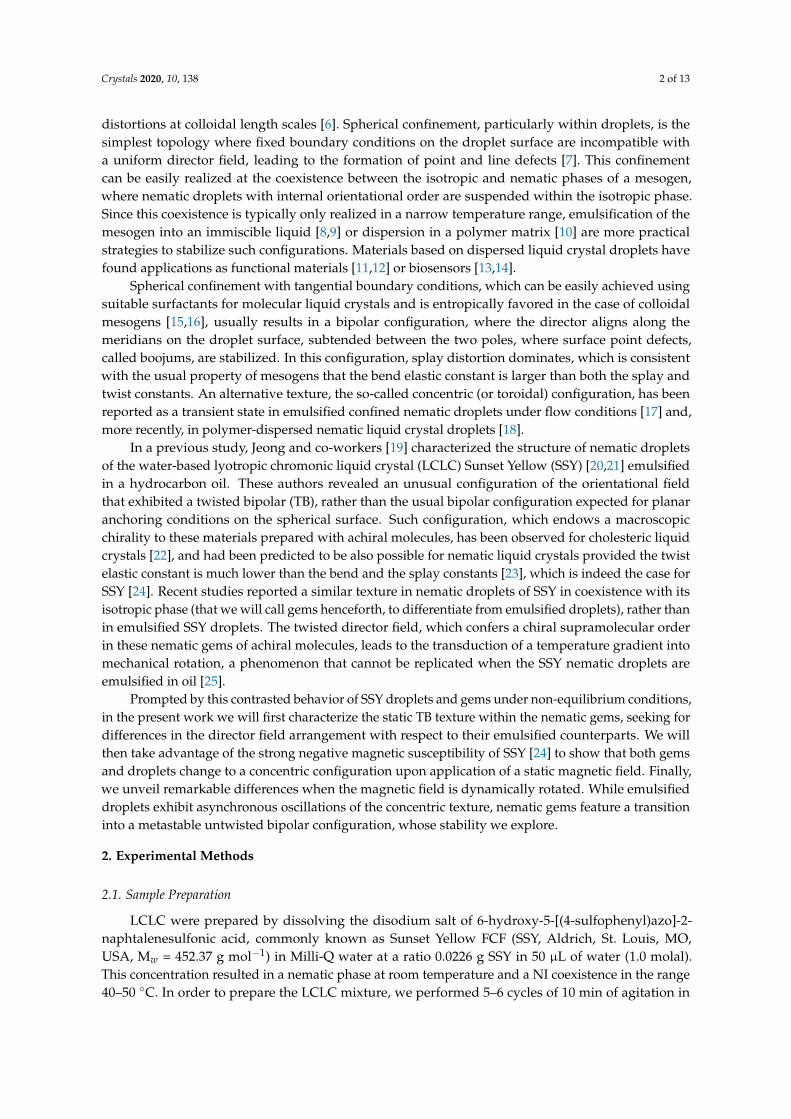
Polarizing microscopy was carried out in a custom optical setup (Figure 1a), built toinclude a custom-made permanent magnet assembly that provided a homogeneous magnetic fieldperpendicular to the direction of light propagation, within a region much larger than the field of view,featuring a maximum strength of 0.4 T. The magnet was built using a Halbach cylindrical array [28]consisting on eight identical N52-grade Nd–Fe–B cubic magnets (cube size = 25.4 mm, K&J Magnetics).The magnets were assembled, with the suitable geometric arrangement, using a 3D-printed PLAenclosure (see Figure 1a and Ref. [29] for details). This is an extremely cost-effective setup to generate amagnetic field that is strong and homogeneous enough to align usual thermotropic mesogens, and alsosome lyotropic materials, such as SSY. The strength of the magnetic field was adjusted by modifyingthe vertical positioning of the sample with respect to the magnet plane. Both the orientation andthe strength of the magnetic field where adjusted with motorized stages controlled using LabView.Samples were held inside a thermostatic oven (T) build with Thorlabs SM1 tube components and tapeheater, and controlled with a Thorlabs TC200 device. The oven is held together with a 660 nm ledlight source (L, Thorlabs M660L2) and a polarizer (P). The observation module is placed in a three-axistranslation stage and features an objective tube (O), an analyzer (A) and a camera (C). A mirror block(M) is used to increase the mechanical stability of the assembly.
β(a) (b)
(c)
αanPαpol
A
L
P
T
B
OM
CA
X
YZ
Figure 1. (a) Experimental setup. A homemade polarizing microscope is fitted with a permanentmagnet array that imposes a magnetic field in the XY plane. (b) Typical ensemble of SunsetYellow (SSY) nematic gems in coexistence with isotropic liquid as seen between crossed polarizers.The orientation of the symmetry axis of a gem with respect to the horizontal defines the angle β.(c) Geometrical parameters used in the analysis of the director field profile through the center of thegems. Scale bar is 100 µm.
Images of nematic droplets coexisting with the isotropic phase or dispersed in an isotropic oil(Figure 1b) were captured with a uEye monochrome CCD camera (Edmund Optics), driven with thepublic domain software Micro-Manager, built around the software ImageJ, which was also used forfurther image processing.
Crystals 2020, 10, 138 5 of 13
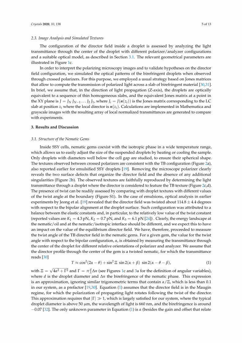
2.3. Image Analysis and Simulated Textures
The configuration of the director field inside a droplet is assessed by analyzing the lighttransmittance through the center of the droplet with different polarizer/analyzer configurationsand a suitable optical model, as described in Section 3.1. The relevant geometrical parameters areillustrated in Figure 1c.
In order to interpret the polarizing microscopy images and to validate hypotheses on the directorfield configuration, we simulated the optical patterns of the birefringent droplets when observedthrough crossed polarizers. For this purpose, we employed a usual strategy based on Jones matricesthat allow to compute the transmission of polarized light across a slab of birefringent material [30,31].In brief, we assume that, in the direction of light propagation (Z-axis), the droplets are opticallyequivalent to a sequence of thin homogeneous slabs, and the equivalent Jones matrix at a point inthe XY plane is J = JN JN−1 . . . J2 J1, where Ji = J(n(zi)) is the Jones matrix corresponding to the LCslab at position zi where the local director is n(zi). Calculations are implemented in Mathematica andgrayscale images with the resulting array of local normalized transmittances are generated to comparewith experiments.
3. Results and Discussion
3.1. Structure of the Nematic Gems
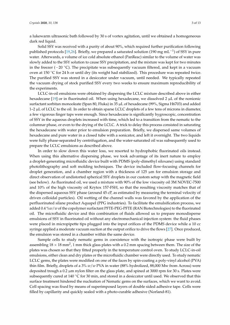
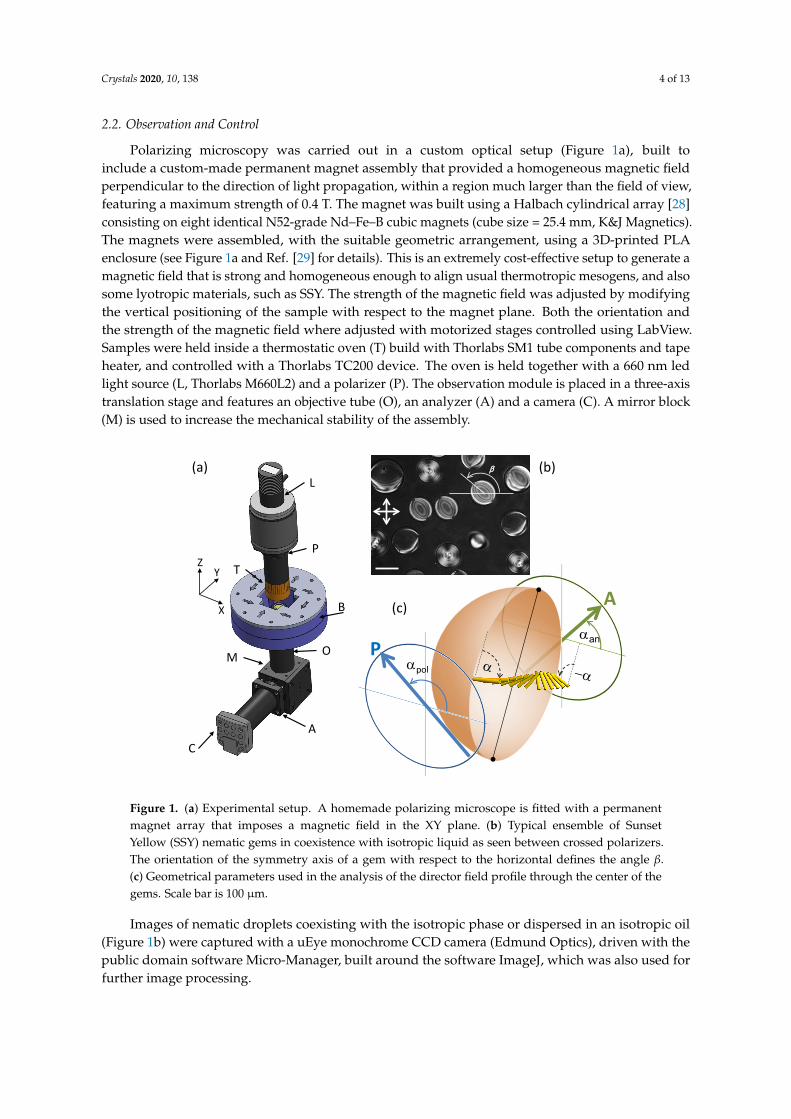
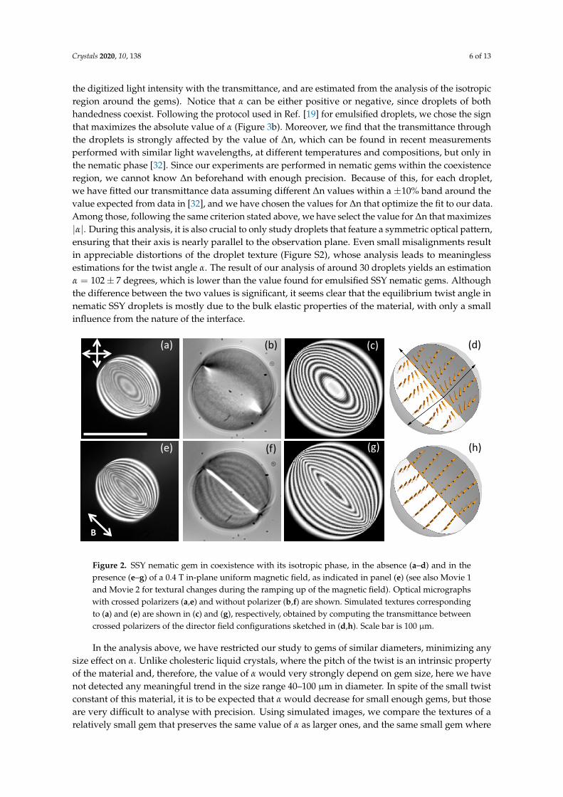
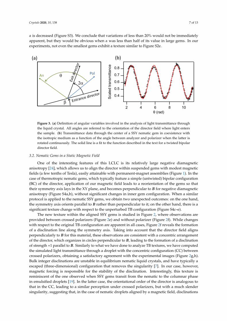
Inside SSY cells, nematic gems coexist with the isotropic phase in a wide temperature range,which allows us to easily adjust the size of the suspended droplets by heating or cooling the sample.Only droplets with diameters well below the cell gap are studied, to ensure their spherical shape.The textures observed between crossed polarizers are consistent with the TB configuration (Figure 2a),also reported earlier for emulsified SSY droplets [19]. Removing the microscope polarizer clearlyreveals the two surface defects that organize the director field and the absence of any additionalsingularities (Figure 2b). The observed textures are faithfully reproduced by determining the lighttransmittance through a droplet where the director is considered to feature the TB texture (Figure 2c,d).The presence of twist can be readily assessed by comparing with droplet textures with different valuesof the twist angle at the boundary (Figure S1). In the case of emulsions, optical analysis in earlierexperiments by Jeong et al. [19] revealed that the director field was twisted about 114.8± 4.4 degreeswith respect to the bipolar alignment at the droplet surface. Such configuration was attributed to abalance between the elastic constants and, in particular, to the relatively low value of the twist constant(reported values are K1 = 4.3 pN, K2 = 0.7 pN, and K3 = 6.1 pN [24]) . Clearly, the energy landscape atthe nematic/oil and at the nematic/isotropic interface should be different, and we expect this to havean impact on the value of the equilibrium director field. We have, therefore, proceeded to measurethe twist angle of the TB director field in the nematic gems. For a given gem, the value for the twistangle with respect to the bipolar configuration, α, is obtained by measuring the transmittance throughthe center of the droplet for different relative orientations of polarizer and analyzer. We assume thatthe director profile through the center of the gem is a twisted nematic, for which the transmittancereads [30]
T ≈ cos2(2α− θ) + sin2 Ξ sin 2(α + β) sin 2(α− θ − β), (1)
with Ξ =√
4α2 + Γ2 and Γ = π dλ ∆n (see Figures 1c and 3a for the definition of angular variables),
where d is the droplet diameter and ∆n the birefringence of the nematic phase. This expressionis an approximation, ignoring similar trigonometric terms that contain α/Ξ, which is less than 0.1in our system, as a prefactor [19,30]. Equation (1) assumes that the director field is in the Mauginregime, for which the polarization of propagating light rotates following the twist of the director.This approximation requires that |Γ| � 1, which is largely satisfied for our system, where the typicaldroplet diameter is above 50 µm, the wavelength of light is 660 nm, and the birefringence is around−0.07 [32]. The only unknown parameter in Equation (1) is α (besides the gain and offset that relate
Crystals 2020, 10, 138 6 of 13
the digitized light intensity with the transmittance, and are estimated from the analysis of the isotropicregion around the gems). Notice that α can be either positive or negative, since droplets of bothhandedness coexist. Following the protocol used in Ref. [19] for emulsified droplets, we chose the signthat maximizes the absolute value of α (Figure 3b). Moreover, we find that the transmittance throughthe droplets is strongly affected by the value of ∆n, which can be found in recent measurementsperformed with similar light wavelengths, at different temperatures and compositions, but only inthe nematic phase [32]. Since our experiments are performed in nematic gems within the coexistenceregion, we cannot know ∆n beforehand with enough precision. Because of this, for each droplet,we have fitted our transmittance data assuming different ∆n values within a ±10% band around thevalue expected from data in [32], and we have chosen the values for ∆n that optimize the fit to our data.Among those, following the same criterion stated above, we have select the value for ∆n that maximizes|α|. During this analysis, it is also crucial to only study droplets that feature a symmetric optical pattern,ensuring that their axis is nearly parallel to the observation plane. Even small misalignments resultin appreciable distortions of the droplet texture (Figure S2), whose analysis leads to meaninglessestimations for the twist angle α. The result of our analysis of around 30 droplets yields an estimationα = 102± 7 degrees, which is lower than the value found for emulsified SSY nematic gems. Althoughthe difference between the two values is significant, it seems clear that the equilibrium twist angle innematic SSY droplets is mostly due to the bulk elastic properties of the material, with only a smallinfluence from the nature of the interface.
(a)
(e)
(b)
(f)
(c) (d)
(g) (h)
B
SSY N gems as a function of B-field. Better because it is stable
Figure 2. SSY nematic gem in coexistence with its isotropic phase, in the absence (a–d) and in thepresence (e–g) of a 0.4 T in-plane uniform magnetic field, as indicated in panel (e) (see also Movie 1and Movie 2 for textural changes during the ramping up of the magnetic field). Optical micrographswith crossed polarizers (a,e) and without polarizer (b,f) are shown. Simulated textures correspondingto (a) and (e) are shown in (c) and (g), respectively, obtained by computing the transmittance betweencrossed polarizers of the director field configurations sketched in (d,h). Scale bar is 100 µm.
In the analysis above, we have restricted our study to gems of similar diameters, minimizing anysize effect on α. Unlike cholesteric liquid crystals, where the pitch of the twist is an intrinsic propertyof the material and, therefore, the value of α would very strongly depend on gem size, here we havenot detected any meaningful trend in the size range 40–100 µm in diameter. In spite of the small twistconstant of this material, it is to be expected that α would decrease for small enough gems, but thoseare very difficult to analyse with precision. Using simulated images, we compare the textures of arelatively small gem that preserves the same value of α as larger ones, and the same small gem where
Crystals 2020, 10, 138 7 of 13
α is decreased (Figure S3). We conclude that variations of less than 20% would not be immediatelyapparent, but they would be obvious when α was less than half of its value in large gems. In ourexperiments, not even the smallest gems exhibit a texture similar to Figure S2e.
0.8
0.7
0.6
0.5
0.4Scal
ed tr
ansm
ittan
ce108642
θ (rad)
Gota 6
Coefficient values ± one standard deviationd =81.1 ± 0beta =2.65 ± 0A =0.51796 ± 0.00145B =0.18255 ± 0.00152n =0.07 ± 0apol =0.189 ± 0a0 =-1.674 ± 0.00295
96º
Range: 102 +/- 7 º, about 30 droplets
(a) (b)
θ PolAn
2α
β
Figure 3. (a) Definition of angular variables involved in the analysis of light transmittance throughthe liquid crystal. All angles are referred to the orientation of the director field where light entersthe sample. (b) Transmittance data through the center of a SSY nematic gem in coexistence withthe isotropic medium as a function of the angle between analyzer and polarizer when the latter isrotated continuously. The solid line is a fit to the function described in the text for a twisted bipolardirector field.
3.2. Nematic Gems in a Static Magnetic Field
One of the interesting features of this LCLC is its relatively large negative diamagneticanisotropy [24], which allows us to align the director within suspended gems with modest magneticfields (a few tenths of Tesla), easily attainable with permanent-magnet assemblies (Figure 1). In thecase of thermotropic nematic gems, which typically feature a simple (untwisted) bipolar configuration(BC) of the director, application of our magnetic field leads to a reorientation of the gems so thattheir symmetry axis lays in the XY plane, and becomes perpendicular to B for negative diamagneticanisotropy (Figure S4a,b), without significant changes in inner gem configuration. When a similarprotocol is applied to the nematic SSY gems, we obtain two unexpected outcomes: on the one hand,the symmetry axis orients parallel to B rather than perpendicular to it; on the other hand, there is asignificant texture change with respect to the unperturbed TB configuration (Figure S4c–e).
The new texture within the aligned SSY gems is studied in Figure 2, where observations areprovided between crossed polarizers (Figure 2e) and without polarizer (Figure 2f). While changeswith respect to the original TB configuration are apparent in all cases, Figure 2f reveals the formationof a disclination line along the symmetry axis. Taking into account that the director field alignsperpendicularly to B for this material, these observations are consistent with a concentric arrangementof the director, which organizes in circles perpendicular to B, leading to the formation of a disclinationof strength +1 parallel to B. Similarly to what we have done to analyze TB textures, we have computedthe simulated light transmittance through a droplet with the concentric configuration (CC) betweencrossed polarizers, obtaining a satisfactory agreement with the experimental images (Figure 2g,h).Bulk integer disclinations are unstable in equilibrium nematic liquid crystals, and have typically aescaped (three-dimensional) configuration that removes the singularity [7]. In our case, however,magnetic forcing is responsible for the stability of the disclination. Interestingly, this texture isreminiscent of the one observed when SSY gems transit from the nematic to the columnar phasein emulsified droplets [19]. In the latter case, the orientational order of the director is analogous tothat in the CC, leading to a similar perception under crossed polarizers, but with a much slendersingularity, suggesting that, in the case of nematic droplets aligned by a magnetic field, disclinations
Crystals 2020, 10, 138 8 of 13
are always nonsingular. The formation of the CC in our system in the presence of a magnetic fieldcan be understood by considering the equilibrium texture in the absence of an external field for thismaterial with negative diamagnetic anisotropy. In the outer region of the gems, the director fieldis nearly perpendicular to the droplet axis, so the arrangement is close to concentric and far frombipolar in that region. Progressive application of the magnetic field leads to the reorientation of outerlayers first, since they are less bound by elastic constraints. As the outer region becomes orientedperpendicular to B, the CC propagates towards the center of the droplet for higher fields (Figure S4).Notice that, since K3 > K1 in this material [24], the CC, where bend distortion dominates, has higherelastic energy than the BC, where splay dominates. Therefore, the organization into the higher energyCC by the magnetic field must be attributed to the presence of twist in the initial texture, unlikein ordinary thermotropic LCs, where the absence of twist prevents the concentric magnetic fieldalignment (Figure S4).
3.3. Transition to Bipolar Nematic Gems Under a Rotating Magnetic Field
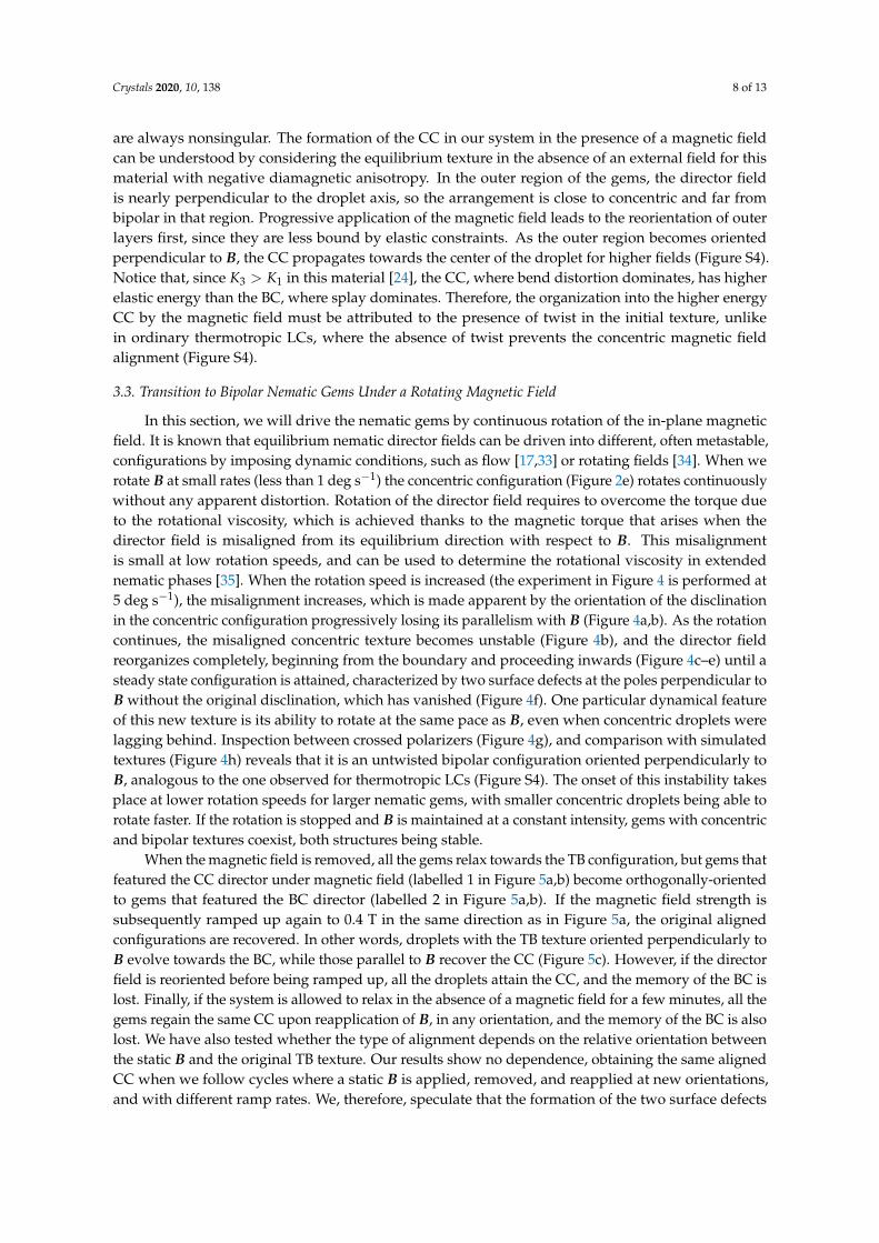
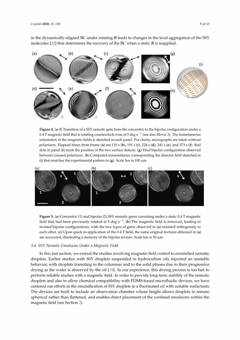
In this section, we will drive the nematic gems by continuous rotation of the in-plane magneticfield. It is known that equilibrium nematic director fields can be driven into different, often metastable,configurations by imposing dynamic conditions, such as flow [17,33] or rotating fields [34]. When werotate B at small rates (less than 1 deg s−1) the concentric configuration (Figure 2e) rotates continuouslywithout any apparent distortion. Rotation of the director field requires to overcome the torque dueto the rotational viscosity, which is achieved thanks to the magnetic torque that arises when thedirector field is misaligned from its equilibrium direction with respect to B. This misalignmentis small at low rotation speeds, and can be used to determine the rotational viscosity in extendednematic phases [35]. When the rotation speed is increased (the experiment in Figure 4 is performed at5 deg s−1), the misalignment increases, which is made apparent by the orientation of the disclinationin the concentric configuration progressively losing its parallelism with B (Figure 4a,b). As the rotationcontinues, the misaligned concentric texture becomes unstable (Figure 4b), and the director fieldreorganizes completely, beginning from the boundary and proceeding inwards (Figure 4c–e) until asteady state configuration is attained, characterized by two surface defects at the poles perpendicular toB without the original disclination, which has vanished (Figure 4f). One particular dynamical featureof this new texture is its ability to rotate at the same pace as B, even when concentric droplets werelagging behind. Inspection between crossed polarizers (Figure 4g), and comparison with simulatedtextures (Figure 4h) reveals that it is an untwisted bipolar configuration oriented perpendicularly toB, analogous to the one observed for thermotropic LCs (Figure S4). The onset of this instability takesplace at lower rotation speeds for larger nematic gems, with smaller concentric droplets being able torotate faster. If the rotation is stopped and B is maintained at a constant intensity, gems with concentricand bipolar textures coexist, both structures being stable.
When the magnetic field is removed, all the gems relax towards the TB configuration, but gems thatfeatured the CC director under magnetic field (labelled 1 in Figure 5a,b) become orthogonally-orientedto gems that featured the BC director (labelled 2 in Figure 5a,b). If the magnetic field strength issubsequently ramped up again to 0.4 T in the same direction as in Figure 5a, the original alignedconfigurations are recovered. In other words, droplets with the TB texture oriented perpendicularly toB evolve towards the BC, while those parallel to B recover the CC (Figure 5c). However, if the directorfield is reoriented before being ramped up, all the droplets attain the CC, and the memory of the BC islost. Finally, if the system is allowed to relax in the absence of a magnetic field for a few minutes, all thegems regain the same CC upon reapplication of B, in any orientation, and the memory of the BC is alsolost. We have also tested whether the type of alignment depends on the relative orientation betweenthe static B and the original TB texture. Our results show no dependence, obtaining the same alignedCC when we follow cycles where a static B is applied, removed, and reapplied at new orientations,and with different ramp rates. We, therefore, speculate that the formation of the two surface defects
Crystals 2020, 10, 138 9 of 13
in the dynamically-aligned BC under rotating B leads to changes in the local aggregation of the SSYmolecules [32] that determines the recovery of the BC when a static B is reapplied.Frame 1 Frame 219
Frame 381
Frame 746Frame 447 Frame 481
(a) (b) (c)
(d) (e) (f)
CCW Rotation
Frame 381Substack(1,201,334)_2_Cambio_IND_CAMPO20190916_Aug10_Temp38_SSY_Magentictwist_72speriodo_subirbajar tiempo
(g)
(h)
(i)
Figure 4. (a–f) Transition of a SSY nematic gem from the concentric to the bipolar configuration under a0.4 T magnetic field that is rotating counterclock-wise at 5 deg s−1 (see also Movie 3). The instantaneousorientation of the magnetic fields is sketched in each panel. For clarity, micrographs are taken withoutpolarizers. Elapsed times from frame (a) are 110 s (b), 191 s (c), 224 s (d), 241 s (e), and 373 s (f). Reddots in panel (f) mark the position of the two surface defects. (g) Final bipolar configuration observedbetween crossed polarizers. (h) Computed transmittance corresponding the director field sketched in(i) that matches the experimental pattern in (g). Scale bar is 100 µm.
B B
(a) (b) (c)
Scale: 50 microns
B=0
1
1
2
1
1
2
Figure 5. (a) Concentric (1) and bipolar (2) SSY nematic gems coexisting under a static 0.4 T magneticfield that had been previously rotated at 5 deg s−1. (b) The magnetic field is removed, leading totwisted bipolar configurations, with the two types of gems observed in (a) oriented orthogonaly toeach other. (c) Upon quick re-application of the 0.4 T field, the same original textures obtained in (a)are recovered, illustrating a memory of the bipolar texture. Scale bar is 50 µm.
3.4. SSY Nematic Emulsions Under a Magnetic Field
In this last section, we extend the studies involving magnetic field control to emulsified nematicdroplets. Earlier studies with SSY droplets suspended in hydrocarbon oils reported an unstablebehavior, with droplets transiting to the columnar and to the solid phases due to their progressivedrying as the water is absorved by the oil [19]. In our experience, this drying process is too fast toperform reliable studies with a magnetic field. In order to provide long-term stability of the nematicdroplets and also to allow chemical compatibility with PDMS-based microfluidic devices, we havecentered our efforts in the emulsification of SSY droplets in a fluorinated oil with suitable surfactants.The devices are built to include an observation chamber whose height allows droplets to remainspherical rather than flattened, and enables direct placement of the confined emulsions within themagnetic field (see Section 2).
Crystals 2020, 10, 138 10 of 13
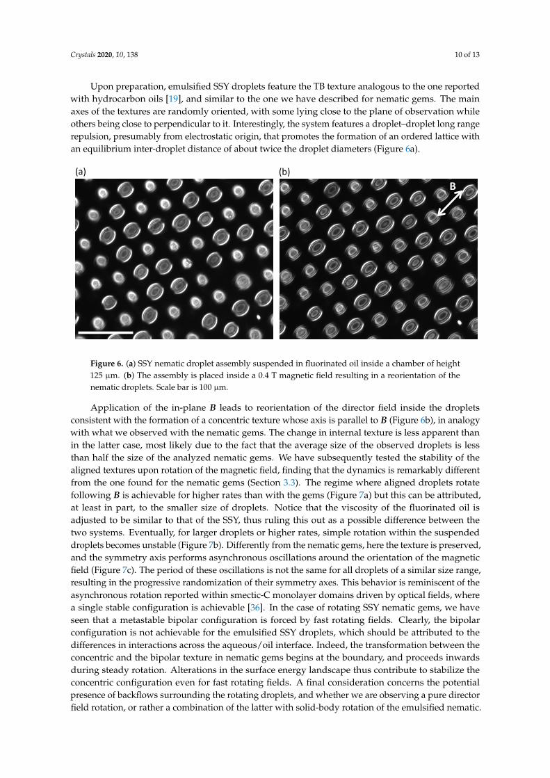
Upon preparation, emulsified SSY droplets feature the TB texture analogous to the one reportedwith hydrocarbon oils [19], and similar to the one we have described for nematic gems. The mainaxes of the textures are randomly oriented, with some lying close to the plane of observation whileothers being close to perpendicular to it. Interestingly, the system features a droplet–droplet long rangerepulsion, presumably from electrostatic origin, that promotes the formation of an ordered lattice withan equilibrium inter-droplet distance of about twice the droplet diameters (Figure 6a).Emulsions in fluorinated oil
B = 400mTB = 0
Rotating Bfield. Time in seconds. 10 deg/s
Check calibration: different camera and setup
B(a) (b)
190726_SSY_ACEITEFLUORADO_MICROEMULSION_CAMPMAG_2
Figure 6. (a) SSY nematic droplet assembly suspended in fluorinated oil inside a chamber of height125 µm. (b) The assembly is placed inside a 0.4 T magnetic field resulting in a reorientation of thenematic droplets. Scale bar is 100 µm.
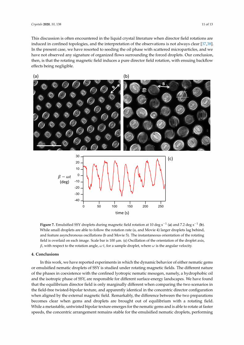
Application of the in-plane B leads to reorientation of the director field inside the dropletsconsistent with the formation of a concentric texture whose axis is parallel to B (Figure 6b), in analogywith what we observed with the nematic gems. The change in internal texture is less apparent thanin the latter case, most likely due to the fact that the average size of the observed droplets is lessthan half the size of the analyzed nematic gems. We have subsequently tested the stability of thealigned textures upon rotation of the magnetic field, finding that the dynamics is remarkably differentfrom the one found for the nematic gems (Section 3.3). The regime where aligned droplets rotatefollowing B is achievable for higher rates than with the gems (Figure 7a) but this can be attributed,at least in part, to the smaller size of droplets. Notice that the viscosity of the fluorinated oil isadjusted to be similar to that of the SSY, thus ruling this out as a possible difference between thetwo systems. Eventually, for larger droplets or higher rates, simple rotation within the suspendeddroplets becomes unstable (Figure 7b). Differently from the nematic gems, here the texture is preserved,and the symmetry axis performs asynchronous oscillations around the orientation of the magneticfield (Figure 7c). The period of these oscillations is not the same for all droplets of a similar size range,resulting in the progressive randomization of their symmetry axes. This behavior is reminiscent of theasynchronous rotation reported within smectic-C monolayer domains driven by optical fields, wherea single stable configuration is achievable [36]. In the case of rotating SSY nematic gems, we haveseen that a metastable bipolar configuration is forced by fast rotating fields. Clearly, the bipolarconfiguration is not achievable for the emulsified SSY droplets, which should be attributed to thedifferences in interactions across the aqueous/oil interface. Indeed, the transformation between theconcentric and the bipolar texture in nematic gems begins at the boundary, and proceeds inwardsduring steady rotation. Alterations in the surface energy landscape thus contribute to stabilize theconcentric configuration even for fast rotating fields. A final consideration concerns the potentialpresence of backflows surrounding the rotating droplets, and whether we are observing a pure directorfield rotation, or rather a combination of the latter with solid-body rotation of the emulsified nematic.
Crystals 2020, 10, 138 11 of 13
This discussion is often encountered in the liquid crystal literature when director field rotations areinduced in confined topologies, and the interpretation of the observations is not always clear [37,38].In the present case, we have resorted to seeding the oil phase with scattered microparticles, and wehave not observed any signature of organized flows surrounding the forced droplets. Our conclusion,then, is that the rotating magnetic field induces a pure director field rotation, with ensuing backfloweffects being negligible.
-40
-30
-20
-10
0
10
20
30
250200150100500
B
(a) (b)
Rotating Bfield. 10 deg/s (T=36s) Rotating Bfield. RATE? Maybe also 10 deg/s. It is 7.2deg/s (T=50s)
time (s)
𝛽𝛽 − 𝜔𝜔𝜔𝜔
(c)
β
190726_SSY_ACEITEFLUORADO_MICROEMULSION_CAMPMAG_!
(deg)
Figure 7. Emulsified SSY droplets during magnetic field rotation at 10 deg s−1 (a) and 7.2 deg s−1 (b).While small droplets are able to follow the rotation rate (a, and Movie 4) larger droplets lag behind,and feature asynchronous oscillations (b and Movie 5). The instantaneous orientation of the rotatingfield is overlaid on each image. Scale bar is 100 µm. (c) Oscillation of the orientation of the droplet axis,β, with respect to the rotation angle, ω t, for a sample droplet, where ω is the angular velocity.
4. Conclusions
In this work, we have reported experiments in which the dynamic behavior of either nematic gemsor emulsified nematic droplets of SSY is studied under rotating magnetic fields. The different natureof the phases in coexistence with the confined lyotropic nematic mesogen, namely, a hydrophobic oiland the isotropic phase of SSY, are responsible for different surface-energy landscapes. We have foundthat the equilibrium director field is only marginally different when comparing the two scenarios inthe field-free twisted-bipolar texture, and apparently identical in the concentric director configurationwhen aligned by the external magnetic field. Remarkably, the difference between the two preparationsbecomes clear when gems and droplets are brought out of equilibrium with a rotating field.While a metastable, untwisted bipolar texture emerges for the nematic gems and is able to rotate at fasterspeeds, the concentric arrangement remains stable for the emulsified nematic droplets, performing
Crystals 2020, 10, 138 12 of 13
asynchronous oscillations about the instantaneous magnetic field orientation and preserving theirintegrity for fast rotating fields.
Our studies present a rare example of a metastable texture in nematic droplets driven by externalforcing, and may be useful to understand the interplay between bulk elasticity and surface anchoringto determine the overall configuration. When involving emulsified nematic droplets, our protocolmay be used to prepare ordered lattices of identical crystallites that may be obtained by the controlleddrying of the aqueous-based mesogen, paving the way for the development of functional materialsbased on colloidal assemblies.
Supplementary Materials: The following are available online at http://www.mdpi.com/2073-4352/10/2/138/s1.
Author Contributions: Conceptualization, J.I.-M. and F.S.; investigation, M.M., B.M.-P., I.V.-C., R.S.H.;writing—original draft preparation, J.I.-M.; writing—review and editing, all authors. All authors have readand agreed to the published version of the manuscript.
Funding: This research was funded by Ministerio de Economía, Industria y Competitividad, Spain (projects FIS2013-41144P and FIS2016-78507-C2-1-P, Agencia Estatal de Investigación/European Regional Development Fund).
Conflicts of Interest: The authors declare no conflict of interest.
References
1. Oswald, P.; Pieranski, P. Nematic and Cholesteric Liquid Crystals : Concepts and Physical Properties Illustrated byExperiments; The Liquid Crystals Book Series; Taylor & Francis: Boca Raton, FL, USA, 2005.
2. Kléman, M.; Lavrentovich, O.D. Soft Matter Physics: An Introduction; Partially Ordered Systems; Springer:New York, NY, USA, 2003.
3. Kleman, M. Defects in liquid crystals. Rep. Prog. Phys. 1989, 52, 555–654. [CrossRef]4. Smalyukh, I.I. Liquid Crystal Colloids. Annu. Rev. Condens. Matter Phys. 2017, 9, 207-226. [CrossRef]5. Tai, J.S.B.; Smalyukh, I.I. Three-dimensional crystals of adaptive knots. Science 2019, 365, 1449–1453.
[CrossRef] [PubMed]6. Senyuk, B.; Liu, Q.; He, S.; Kamien, R.D.; Kusner, R.B.; Lubensky, T.C.; Smalyukh, I. Topological colloids.
Nature 2013, 493, 200–205. [CrossRef] [PubMed]7. Lopez-Leon, T.; Fernandez-Nieves, A. Drops and shells of liquid crystal. Colloid Polym. Sci. 2011, 289, 345–359.
[CrossRef]8. Mondiot, F.; Wang, X.; de Pablo, J.J.; Abbott, N.L. Liquid crystal-based emulsions for synthesis of spherical
and non-spherical particles with chemical patches. J. Am. Chem. Soc. 2013, 135, 9972–9975. [CrossRef][PubMed]
9. Musevic, I. Liquid Crystal Colloids. In Soft and Biological Matter; Springer Nature: Cham, Switzerland, 2017.10. Ondris-Crawford, R.; Boyko, E.P.; Wagner, B.G.; Erdmann, J.H.; Žumer, S.; Doane, J.W. Microscope textures
of nematic droplets in polymer dispersed liquid crystals. J. Appl. Phys. 1991, 69, 6380–6386. [CrossRef]11. Miller, D.S.; Wang, X.; Abbott, N.L. Design of Functional Materials based on Liquid Crystalline Droplets.
Chem. Mater. 2014, 26, 496–506. [CrossRef]12. Hakemi, H. Polymer-dispersed liquid crystal technology ‘industrial evolution and current market situation’.
Liq. Cryst. Today 2017, 26, 70–73. [CrossRef]13. Sivakumar, S.; Wark, K.L.; Gupta, J.K.; Abbott, N.L.; Caruso, F. Liquid Crystal Emulsions as the Basis of
Biological Sensors for the Optical Detection of Bacteria and Viruses. Adv. Funct. Mater. 2009, 19, 2260–2265.[CrossRef]
14. Manna, U.; Zayas-Gonzalez, Y.M.; Carlton, R.J.; Caruso, F.; Abbott, N.L.; Lynn, D.M. Liquid crystal chemicalsensors that cells can wear. Angew. Chem. Int. Ed. Engl. 2013, 52, 14011–14015. [CrossRef] [PubMed]
15. Tone, C.M.; De Santo, M.P.; Buonomenna, M.G.; Golemme, G.; Ciuchi, F. Dynamical homeotropic and planaralignments of chromonic liquid crystals. Soft Matter 2012, 8, 8478. [CrossRef]
16. Jeong, J.; Han, G.; Johnson, A.T.; Collings, P.J.; Lubensky, T.C.; Yodh, A.G. Homeotropic alignment oflyotropic chromonic liquid crystals using noncovalent interactions. Langmuir 2014, 30, 2914–2920. [CrossRef]
17. Fernández-Nieves, A.; Link, D.; Márquez, M.; Weitz, D. Topological Changes in Bipolar Nematic Dropletsunder Flow. Phys. Rev. Lett. 2007, 98, 087801. [CrossRef] [PubMed]
Crystals 2020, 10, 138 13 of 13
18. Jiang, J.; Yang, D.K. Bipolar to toroidal configuration transition in liquid crystal droplets. Liq. Cryst. 2017,45, 102–111. [CrossRef]
19. Jeong, J.; Davidson, Z.S.; Collings, P.J.; Lubensky, T.C.; Yodh, A.G. Chiral symmetry breaking and surfacefaceting in chromonic liquid crystal droplets with giant elastic anisotropy. Proc. Natl. Acad. Sci. USA 2014,111, 1742–1747. [CrossRef]
20. Tam-Chang, S.W.; Huang, L. Chromonic liquid crystals: properties and applications as functional materials.Chem. Commun. (Camb.) 2008, 1957–1967. [CrossRef]
21. Park, H.S.; Lavrentovich, O., Lyotropic Chromonic Liquid Crystals:Emerging Applications. In Liquid CrystalsBeyond Displays: Chemistry, Physics, and Applications; Li, Q., Ed.; John Wiley & Sons, Inc.: Hoboken, NJ, USA,2012; Chapter 14.
22. Xu, F.; Crooker, P. Chiral nematic droplets with parallel surface anchoring. Phys. Rev. E 1997, 56, 6853–6860.[CrossRef]
23. Drzaic, P.S. A case of mistaken identity: spontaneous formation of twisted bipolar droplets from achiralnematic materials. Liq. Cryst. 1999, 26, 623–627. [CrossRef]
24. Zhou, S.; Nastishin, Y.; Omelchenko, M.; Tortora, L.; Nazarenko, V.; Boiko, O.; Ostapenko, T.; Hu, T.;Almasan, C.; Sprunt, S.; et al. Elasticity of Lyotropic Chromonic Liquid Crystals Probed by DirectorReorientation in a Magnetic Field. Phys. Rev. Lett. 2012, 109, 037801. [CrossRef]
25. Ignes-Mullol, J.; Poy, G.; Oswald, P. Continuous Rotation of Achiral Nematic Liquid Crystal Droplets Drivenby Heat Flux. Phys. Rev. Lett. 2016, 117, 057801. [CrossRef] [PubMed]
26. Park, H.S.; Kang, S.W.; Tortora, L.; Nastishin, Y.; Finotello, D.; Kumar, S.; Lavrentovich, O.D. Self-assemblyof lyotropic chromonic liquid crystal Sunset Yellow and effects of ionic additives. J. Phys. Chem. B 2008,112, 16307–16319. [CrossRef] [PubMed]
27. Abate, A.R.; Weitz, D.A. Syringe-vacuum microfluidics: A portable technique to create monodisperseemulsions. Biomicrofluidics 2011, 5, 14107. [CrossRef]
28. Soltner, H.; Blümler, P. Dipolar Halbach magnet stacks made from identically shaped permanent magnetsfor magnetic resonance. Concepts Magn. Reson. Part A 2010, 36A, 211–222. [CrossRef]
29. Guillamat, P.; Ignes-Mullol, J.; Sagues, F. Control of active liquid crystals with a magnetic field. Proc. Natl.Acad. Sci. USA 2016, 113, 5498–502. [CrossRef]
30. Yeh, P.; Gu, C. Optics of Liquid Crystal Displays; Wiley Series in Pure And Applied Optics; Wiley: New York,NY, USA, 1999.
31. Ellis, P.W.; Pairam, E.; Fernández-Nieves, A. Simulating optical polarizing microscopy textures using Jonescalculus: A review exemplified with nematic liquid crystal tori. J. Phys. Appl. Phys. 2019, 52, 213001.[CrossRef]
32. Horowitz, V.R.; Janowitz, L.A.; Modic, A.L.; Heiney, P.A.; Collings, P.J. Aggregation behavior and chromonicliquid crystal properties of an anionic monoazo dye. Phys. Rev. E 2005, 72, 041710. [CrossRef]
33. Giomi, L.; Kos, Z.; Ravnik, M.; Sengupta, A. Cross-talk between topological defects in different fieldsrevealed by nematic microfluidics. Proc. Natl. Acad. Sci. USA 2017, 114, E5771–E5777. [CrossRef]
34. Xu, F.; Kitzerow, H.; Crooker, P.P. Electric-field effects on nematic droplets with negative dielectric anisotropy.Phys. Rev. A 1992, 46, 6535–6540. [CrossRef]
35. Oswald, P. Easy axis memorization with active control of the azimuthal anchoring energy in nematic liquidcrystals. EPL (Europhys. Lett.) 2014, 107, 26003. [CrossRef]
36. Burriel, P.; Ignes-Mullol, J.; Reigada, R.; Sagues, F. Collective molecular precession induced by rotatingillumination in photosensitive Langmuir monolayers. Langmuir 2006, 22, 187–193. [CrossRef] [PubMed]
37. Yoshioka, J.; Ito, F.; Suzuki, Y.; Takahashi, H.; Takizawa, H.; Tabe, Y. Director/barycentric rotation incholesteric droplets under temperature gradient. Soft Matter 2014, 10, 5869–5877. [CrossRef] [PubMed]
38. Poy, G.; Oswald, P. Do Lehmann cholesteric droplets subjected to a temperature gradient rotate as rigidbodies? Soft Matter 2016, 12, 2604–2611. [CrossRef] [PubMed]
c© 2020 by the authors. Licensee MDPI, Basel, Switzerland. This article is an open accessarticle distributed under the terms and conditions of the Creative Commons Attribution(CC BY) license (http://creativecommons.org/licenses/by/4.0/).