NEII PERFORMANCE STANDARDS COMMITTEE April 15, 2014 · 2019-08-27 · Barry Blackaby Otis Elevator...
62
Code & Safety Office 4034 North Hampton Brook Drive Hamburg, New York 14075 Office: 585.302.0813 Cell: 585.354.6772 NEII and NEII logo – Registered, U.S. Patent and Trademark Office NEII ® PERFORMANCE STANDARDS COMMITTEE April 15, 2014 1. Call to Order. Chairman Joe Busse called the meeting to order at 8:30 a.m. on April 15, 2014 at Fujitec America, 7258 Innovation Way, Mason, Ohio 45050. 2. Record of Attendance. Name Company Brian Black NEII Barry Blackaby Otis Elevator Company Jeff Blain Schlindler Elevator Company Joe Busse Fujitec America Bob Caporale (teleconference) Elevator World Doug Henderson ThyssenKrupp Elevator Corporation Tom Hausenbauer NAEC (Minnesota Elevator Inc.) Mike Lewis KONE, Inc. 3. Announcements. Jay Popp was unable to attend the meeting. 4. Adoption of Agenda. The agenda posted on the committee website was adopted. 5. Approval of October 8, 2013 Minutes. The minutes posted on the committee website were approved. It was noted that Jay still needs to draft a paper on elevator‐specific provisions for LEED certification. Barry will assist on this. Brian will follow up on the A17.1 vs A117.1 white paper.
Transcript of NEII PERFORMANCE STANDARDS COMMITTEE April 15, 2014 · 2019-08-27 · Barry Blackaby Otis Elevator...

Code & Safety Office 4034 North Hampton Brook Drive Hamburg, New York 14075 Office: 585.302.0813 Cell: 585.354.6772
NEII and NEII logo – Registered, U.S. Patent and Trademark Office
NEII® PERFORMANCE STANDARDS COMMITTEE
April 15, 2014 1. Call to Order. Chairman Joe Busse called the meeting to order at 8:30 a.m. on April 15, 2014 at Fujitec America, 7258 Innovation Way, Mason, Ohio 45050. 2. Record of Attendance.
Name Company Brian Black NEII Barry Blackaby Otis Elevator Company Jeff Blain Schlindler Elevator Company Joe Busse Fujitec America Bob Caporale (teleconference) Elevator World Doug Henderson ThyssenKrupp Elevator Corporation Tom Hausenbauer NAEC (Minnesota Elevator Inc.) Mike Lewis KONE, Inc.
3. Announcements. Jay Popp was unable to attend the meeting. 4. Adoption of Agenda. The agenda posted on the committee website was adopted. 5. Approval of October 8, 2013 Minutes. The minutes posted on the committee website were approved. It was noted that Jay still needs to draft a paper on elevator‐specific provisions for LEED certification. Barry will assist on this. Brian will follow up on the A17.1 vs A117.1 white paper.
6. Personnel.
Please see Attachment #1 for a copy of the Committee Roster. Members are requested to advise Brian Black of any corrections that are required.
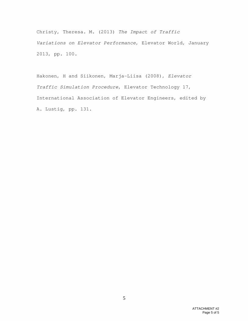
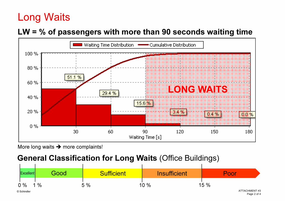
7. Election of Chairman. Barry noted Joe’s chairing the committee gives them an opportunity to discuss electrical matters when they cannot all attend an A17 Electrical Committee meeting. This item is tabled until the next meeting. 8. Destination Dispatch. a. Performance criteria. The committee reviewed Attachment #2. Jeff offered Attachment #3 and Attachment #4 for review and discussed average‐time‐to‐destination being a metric that did not seem to work well. Average‐number‐of‐intermediate‐stops (2‐3 ideal) is a better benchmark as is average‐time‐to‐service. Bob noted that different algorithms used by different companies make a comparison difficult for the consultants. He also suggested that buildings and traffic patterns have become more complex because destination dispatch permits this. Doug noted the average waiting time and travel time have been constant metric in the industry for both conventional and destination systems, and stated we shouldn’t complicate this too much in NEII‐1. Barry mentioned an ISO working group has been formed to standardize destination dispatch definitions. Joe suggested we use the term “IS” for intermediary stops and standardize our definitions and terminology. He also asked Bob and Jeff to raise this at the IAEC Forum in Denver next week. Bob will develop an example of the approach used by the consultants to discuss at our next meeting. Barry will ask Theresa Christy to get involved as well. Bob raised the question of whether we should provide performance metrics in NEII‐1. Doug asked whether we should come up with a percentage of reduction of time over conventional systems. He also suggested we could develop some general performance criteria that can be applied to both conventional and destination dispatch systems.

The committee agreed that hybrid systems should also be addressed. b. Accessibility criteria. The committee agreed to abandon the approach shown in Attachment #5. Attachment #6 will serve as the basis of the more general requirements of our NEII‐1 Guidelines. c. ASME A17.5. Barry noted the destination dispatch hall call consoles are “operating devices” as specified in the scope in A17.5 and that this is problematic, particularly for features like touch screens. 9. Part 7, Maintenance Guidelines. Barry reported the Doug LeBrecque wrote an article on MCPs for NEII Now (Attachment #7) that can be used as a foundation for the NEII‐1 piece. 10. Energy Efficiency. a. ASHRAE 90.1‐2010 and 2012 Supplement. Brian reported ASHRAE 90.1 now references A17.1/B44 for specifications on reduced‐speed escalators and moving walks as shown in Attachment #8. b. ISO TC 178/WG10 progress.
Barry reported ISO 25745 Part 2 is completed, providing a rating criteria on a per elevator basis. The final draft will be posted on NEII Talk. ASHRAE 90.1 will reference this once it’s published. Barry will look at the NEII‐1 Energy Efficiency Standard and suggest changes to include references to the ASHRAE 90.1 provisions. Bob forwarded a letter from ACEEE (Attachment #9) regarding a White Paper on energy efficiency and elevators. Barry offered to represent NEII on their Advisory Committee.

11. NEII®‐1 Publication.
NEII®‐1 is on the NEII web site, http://www.neii.org/neii‐1/neii‐1.cfm. 12. Review and Update of NEII®‐1 Parts 1, 4, 5, 6 and 7.
The standards with revisions approved to date are posted in the NEII®‐1 folder on the NEII® Performance Standards Committee web site. Committee members should down load and/or print copies of the latest drafts in advance of the meeting. To access the Performance Standards Committee web site and NEII®‐1 folder click on the following link: http://www.neii.org/members/committees/23/index.cfm.
CAUTION: Please print the Table of Contents and verify you have the latest copy of each document. Many documents have been revised since the last meeting. The files posted in the NEII®‐1 folder on the Performance Standards Committee web site are for Committee members use only. These files may reflect work in progress and may not be the same as the material available in the NEII®‐1 publication available to the general public.
a. Performance Terminology Matrix Examples. Jeff will review Attachment #10 for
the next meeting. Mike will draft an item for power factor. b. Performance Standards Matrix New Escalator and Moving Walk. Barry will review Attachment #11 for the next meeting.
c. Vibration Diagrams. Barry will review Attachment #12 for the next meeting. 13. Review NEII® Long Range Plan – Performance Standards Committee.
The committee reviewed and reaffirmed Attachment #13.
14. New Business. a. Occupant Evacuation Elevators. Barry will ask David McColl for a paper/article. b. Starts‐per‐hour specifications. Joe indicated this has been raised as a concern by some consultants, as has temperature rises/insulation classes. He will draft a paper for consideration.

c. Independence and redundancy. Joe noted that we have had problems with TSSA regarding the Normal Terminal Stopping and the CCC was going to draft a letter. Doug reported the Canadian firms were considering a formal complaint and suggested we hold off on any action until that runs its course. d. OSHPD and seismic issues. The committee discussed the experiences some companies were having with OSHPD and its inspectors. Joe suggested this topic is best covered by the Central Code Committee. e. Green technology (e.g., regenerative drives). This item was tabled until the next meeting. f. Review of mainline disconnect switch provisions in the guidelines. Mike will review this item. 15. NEII® NOW Article. No potential articles were identified. 16. Time and Location of Next Meeting.
October 15, 2014, 8:30 a.m. Mankato, Minnesota
17. Adjournment.
The meeting adjourned at 2:15 PM.
Respectfully submitted,
Brian Black NEII Code & Safety Director

Attachments: 1. Committee Roster 2. Destination Dispatch White Paper draft 3. Destination Dispatch Performance Criteria 4. Traffic Standards and Recommendations 5. Destination Dispatch Accessibility Criteria 6. Destination Dispatch Proposed California Building Code Requirements 7. MCP article from NEII Now 8. ASHRAE 90.1 2012 Supplement 9. ACEEE letter 10. Performance Terminology Matrix Examples 11. Performance Standards Matrix New Escalator and Moving Walk 12. Vibration Diagrams 13. NEII Long Range Plan – Performance Standards Committee
Performance Standards Committee
Name: BRIAN BLACK 725 Title: NEil CODE AND SAFETY DIRECTOR
Company: BDBLACK & ASSOCIATES, LTD. Address: 4034 NORTH HAMPTON BROOK DRIVE
City: HAMBURG State: NY Zip Code: 14075-6410
Country:
Phone 1:
Phone 2:
E-Mail:
Notes:
Name:
Title:
Company:
Address:
UNITED STATES
Area Number Extension Area Number
585 302-0813 Fax 1: 585 302-0841
716 649-6348 Mobile: 585 354-6772
[email protected] Category: Secretary
Alternate to Amy J. Blanken biller NEil Government Affairs Committee Alternate to Edward A. Donoghue NEil Communications Committee
BARRY BLACKABY 425
MANAGER OF WORLD WlDE ELECTRICAL CODES
OTIS ELEVATOR COMPANY
FNEFARMSPRlNGSROAD
City: FARMINGTON
UNITED STATES
State: CT Zip Code: 06032
Country:
Area Number Extension Area Number
Phone 1: 860 676-6459 Fax 1: 860 998-3293
Phone 2: Mobile:
E-Mail: [email protected] Category: Member
Notes: Alternate Member NEil Performance Standards Committee for ISO Activites
Name: JOSEPH BUSSE 300 Title: CHIEF CORPORATE ENGINEER.
Company: FUJITEC AMERICA, INC. Address: 7258 INNOVATION WAY
City: MASON State: OH Zip Code: 45040
Country: UNITED STATES
Area Number
Phone 1: 513 932-8000
Phone 2:
E-Mail: [email protected]
Notes:
Extension
5203 Fax 1:
Mobile:
Area Number
513
513
933-5582
739-0802
Category: Chair
Tuesday, March 25, 2014 NEll and NEll logo- Registered, U.S. Patent and Trademark Office Page 1 of4
ATTACHMENT #1 Page 1 of 4

Performance Standards Committee
Name: ROBERT CAPORALE 186 Title: EDITOR
Company: ELEVA TOR WORLD, INC. Address: 112 KENTWOOD DRIVE
City: DAPHNE State: AL Zip Code: 36526
Country: UNITED STATES
Area Number Extension Area Number
Phone 1: 251 626-2876 Fax 1:
Phone 2: Mobile: 251 510-4683
E-Mail: [email protected] Category: Member
Notes: Liaison member NEil Performance Standards Committee representing Elevator World
Name:
Title:
Company:
Address:
TRICIA DERWINSKI
PRINCIPAL SYSTEMS ENGINEER
OTIS ELEVA TOR COMPANY
FIVE FARM SPRINGS ROAD
276
City: FARMINGTON State: CT Zip Code: 06032-2567
Country: UNITED STATES
Area Number Extension Area Number
Phone 1: 860 676-6268 Fax 1: 860 676-5494
Phone 2: Mobile:
E-Mail: [email protected] Category: Alternate
Notes: Alternate member NEil Performance Standards Committee
Name:
Title:
Company:
Address:
TOM HAUSENBAUER
SALES ENGINEER
MEl TOTAL ELEVA TOR SOLUTIONS
19336 607TH STREET
858
City: MANKATO State: MN Zip Code: 56001
Country: UNITED STATES
Area Number Extension Area Number
Phone 1: 507 382-4221 Fax 1: 507 245-4198
Phone 2: Mobile:
E-Mail: [email protected] Category: Member
Notes: Liaison member NEil Performance Standards Committee representing NAEC
Tuesday, March 25, 2014 NEll and NEll logo- Registered, U.S. Patent and Trademark Office Page 2 of4
ATTACHMENT #1 Page 2 of 4

Performance Standards Committee
Name:
Title:
Company:
Address:
DOUG HENDERSON
ENGINEER
THYSSENKRUPP ELEVA TOR CORPORATION
P. 0 . BOX 370
624
City: MIDDLETON
UNITED STATES
State: TN Zip Code: 38052
Country:
Area Number Extension Area Number
Phone 1: 731 376-3004 Fax 1:
Phone 2: Mobile: 901 652-3649
E-Mail: [email protected] Category: Member
Notes:
Name:
Title:
Company:
Address:
LEWIS MICHAEL 274
PROJECT MANAGER TECHNOLOGY R & D
KONEINC.
700 CENTRAL EXPRESSWAY SOUTH, 4TH FLOOR SUITE 400
City: ALLEN State: TX Zip Code: 75013
Country: UNITED STATES
Area Number Extension Area Number
Phone 1: 469 854-8825 Fax 1: 972 547-1233
Phone 2: Mobile:
E-Mail: [email protected] Category: Member
Notes:
Name:
Title:
Company:
Address:
JAY POPP
EXECUTIVE VICE PRESIDENT
LERCH, BATES & ASSOCIATES INC.
8089 S. LINCOLIN STREET, SUITE 300
202
City: LITTLETON
UNITED STATES
State: CO Zip Code: 80122
Country:
Area Number
Phone 1: 303 795-7956
Phone 2:
Extension
Fax 1:
Mobile:
Area
303
303
Number
797-7109
881-3588
E-Mail: [email protected] Category: Member
Notes: Liaison member NEll Performance Standards Committee representing IAEC
Tuesday, March 25, 2014 NEll and NEil logo- Registered, U.S. Patent and Trademark Office Page3 of4
ATTACHMENT #1 Page 3 of 4

Performance Standards Committee
Name:
Title:
Company:
Address:
VINCENT P. ROBIDERO
NORTH AMERICAN CODE CONSULT ANT
SCHINDLER ELEVA TOR CORPORATION
P. 0. BOX 1935
53
City: MORRISTOWN
UNITED STATES
State: NJ Zip Code: 07962-1935
Country:
Area Number
Phone 1: 973 397-6018
Phone 2:
Extension
Fax 1:
Mobile:
Area
973
973
Number
397-6141
216-8030
E-Mail: [email protected] Category: Member
Notes:
Name:
Title:
Company:
Address:
JOHN STOCKSTILL
CODESANDSTANDARDSENGINEER
THYSSENKRUPP ELEVA TOR CORPORATION
9280 CRESTWYN HILLS DRIVE
854
City: MEMPHIS
UNITED STATES
State: TN Zip Code: 38125
Country:
Area Number Extension
Phone 1: 901 261-1648
Phone 2:
E-Mail: [email protected]
Notes:
----- -- ---- -----
Fax 1:
Mobile:
Area
901
901
Number
261-1660
409-1999
Category: Alternate
Tuesday, March 25,2014 NEll and NEil logo- Registered, U.S. Patent and Trademark Office Page4 of4
ATTACHMENT #1 Page 4 of 4

1
Draft of Destination Oriented Elevator Performance Criteria
By Robert S. Caporale
April 12, 2013
The elevator core may comprise as much as 15%-20% of a
building's floor area therefore determining the proper size
and the number of elevators is an important aspect of
building design. Providing too few elevators can seriously
compromise a building's efficiency and marketability. And
designing a building with more elevators than needed is bad
economics. Therefore a proper and thorough elevator system
traffic analysis must be performed for the elevator
arrangement being proposed.
The number of people served in a given time period is
generally defined as a group of elevator's Handling
Capacity (HC). This HC must be equal to or greater than the
rate at which people arrive at the elevator group to obtain
service.
The passenger arrival rate will be a function of the
building's occupancy, usage and location. Examples of this
are shown in Table 1 which describes the 5-Minute Handling
Capacity (5-Min HC) that an elevator system must be able to
ATTACHMENT #2 Page 1 of 5

2
achieve for various elevator passenger arrival rates that
can be expected for various types of buildings.
Type of Building Arrival Time
Period in Minutes*
5-Min HC as a Percentage of the elevator group’s total population
Business District Office Bldg. Multi-tenant
40 12
Business District Office Bldg. Single tenant
30 15-17
Suburban Office Bldg.
60 8-10
Self-parking Garage
60 8-10
Department Store 60 8-10 Industrial Bldg. 40 12 Table 1: Passenger Arrival Rates
*100% of the population arrives in this number of minutes
The NElI-1 Elevator Performance Standard defines the
“Average Waiting Time (AWT)”, “Average System Response Time
(ASRT)” and “Average Time to Destination (ATTD)" for a
destination oriented elevator system as well as how these
quantities are measured.
When traveling on a destination oriented elevator system a
passenger might have to wait a bit longer than anticipated
for an elevator to arrive in order to get one that will
provide them with a shorter overall trip time to their
ATTACHMENT #2 Page 2 of 5

3
destination. The ATTD that is calculated for a destination
oriented elevator system reflects this as it includes the
time that a passenger can be expected to wait for an
elevator to arrive plus the actual time that they will
travel in an elevator to their desired destination.
With destination oriented elevator systems, the 30-second
interval is no longer a valid measurement of the quality of
service. Instead each passenger's entire elevator trip
experience is considered and the important criteria that
the system must be able to satisfy is the ATTD. Therefore,
when evaluating the quality of elevator service for a
destination oriented elevator system it is necessary to
understand and for the elevator traffic analysis to reflect
this new measure of elevator service.
As previously stated, the 5-Min HC of an elevator system
must be able to accommodate the passenger arrival rate. An
appropriate ATTD must also be achieved for the type of
building in which the elevators will be installed. As long
as the 5-Min HC of the system matches or exceeds the peak
5-Mininute passenger arrival rate and the proper maximum
ATTD is not exceeded the elevator system will provide
adequate elevator service.
ATTACHMENT #2 Page 3 of 5

4
The ATTD and 5-Min HC criteria that should be achieved for
destination oriented elevator systems in various types of
buildings are shown in Table 2.
Type of Building ATTD (Seconds) 5-Min HC (Percent) Business District Office Bldg. Multi-tenant
100–120 12
Business District Office Bldg. Single-tenant
80–100 15–17
Suburban Office Bldg.
100–120 8–10
Self-parking Garage 60 8-10 Department Store 80 12 Industrial Bldg. 120–150 12 Table 2: Destination Dispatch Performance Criteria
The performance criteria must be agreed upon by the
building’s owner and their architects and elevator
consultants as well as the elevator contractor. Traffic
analysis calculations should be developed and made a part
of the elevator project’s documentation.
References:
Strakosch, George. R. (2010); The Vertical Transportation
Handbook, Fourth Edition, John Wiley & Sons, Inc., New
York.
ATTACHMENT #2 Page 4 of 5
5
Christy, Theresa. M. (2013) The Impact of Traffic
Variations on Elevator Performance, Elevator World, January
2013, pp. 100.
Hakonen, H and Siikonen, Marja-Liisa (2008), Elevator
Traffic Simulation Procedure, Elevator Technology 17,
International Association of Elevator Engineers, edited by
A. Lustig, pp. 131.
ATTACHMENT #2 Page 5 of 5

© Schindler
WT = average waiting time for the observed passengers
The waiting time for an individual passenger is the time– from when the passenger registers a landing call (or joins a queue)– until the door of the serving elevator begins to open on the boarding floor
(if the door is not closed when the passenger arrives then the waiting time is zero).
Average Waiting Time
General Classification for Average Waiting Time (Office Buildings)
Excellent Good Sufficient Insufficient Poor
0 s 20 s 30 s 40 s 50 sATTACHMENT #3
Page 1 of 4
© Schindler
LW = % of passengers with more than 90 seconds waiting time
More long waits � more complaints!
Long Waits
General Classification for Long Waits (Office Buildings)
Excellent Good Sufficient Insufficient Poor
0 % 1 % 5 % 10 % 15 %
LONG WAITS
ATTACHMENT #3 Page 2 of 4
© Schindler
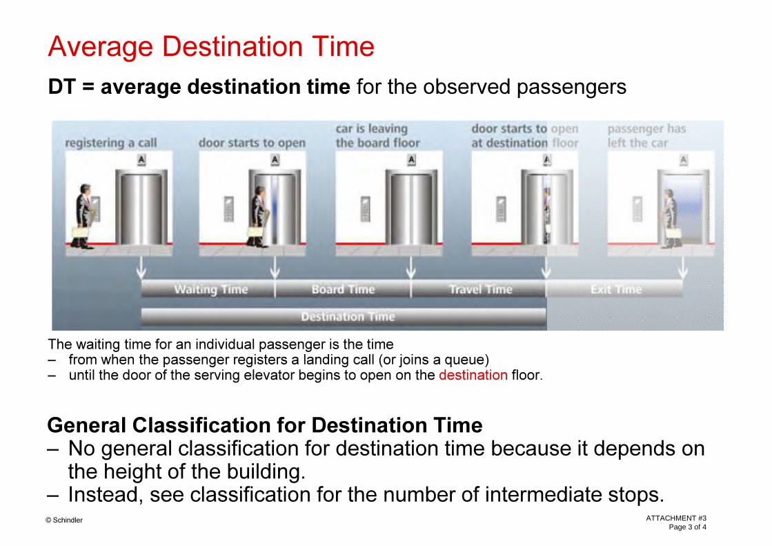
DT = average destination time for the observed passengers
The waiting time for an individual passenger is the time– from when the passenger registers a landing call (or joins a queue)– until the door of the serving elevator begins to open on the destination floor.
Average Destination Time
General Classification for Destination Time– No general classification for destination time because it depends on
the height of the building.– Instead, see classification for the number of intermediate stops.
ATTACHMENT #3 Page 3 of 4

© Schindler
IS = average number of intermediate stops for observed passengers
The number of intermediate stops for an individual passenger is how often the elevator comes to a stop– after leaving the board floor and– before arriving at the destination floor.Example: IS = 0 if every passenger has a direct trip.
Intermediate Stops per Passenger
General Classification for Average Number of Intermediate Stops
Excellent Good Sufficient Insufficient Poor
0 1 2 3 4ATTACHMENT #3
Page 4 of 4
6Simulation Request form S. Latargia 4-4-2011 rev 0
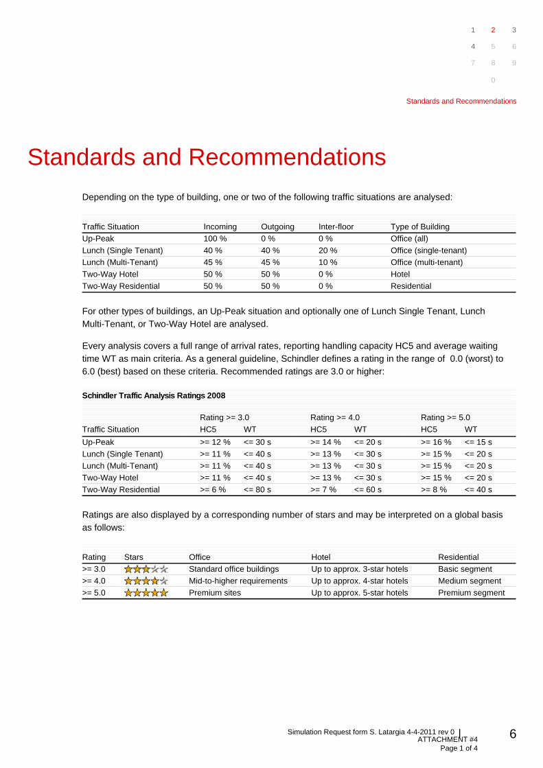
Standards and Recommendations
Depending on the type of building, one or two of the following traffic situations are analysed:
Traffic Situation Incoming Outgoing Inter-floor Type of Building
Up-Peak 100 % 0 % 0 % Office (all)
Lunch (Single Tenant) 40 % 40 % 20 % Office (single-tenant)
Lunch (Multi-Tenant) 45 % 45 % 10 % Office (multi-tenant)
Two-Way Hotel 50 % 50 % 0 % Hotel
Two-Way Residential 50 % 50 % 0 % Residential
For other types of buildings, an Up-Peak situation and optionally one of Lunch Single Tenant, Lunch
Multi-Tenant, or Two-Way Hotel are analysed.
Every analysis covers a full range of arrival rates, reporting handling capacity HC5 and average waiting
time WT as main criteria. As a general guideline, Schindler defines a rating in the range of 0.0 (worst) to
6.0 (best) based on these criteria. Recommended ratings are 3.0 or higher:
Schindler Traffic Analysis Ratings 2008
Rating >= 3.0 Rating >= 4.0 Rating >= 5.0
Traffic Situation HC5 WT HC5 WT HC5 WT
Up-Peak >= 12 % <= 30 s >= 14 % <= 20 s >= 16 % <= 15 s
Lunch (Single Tenant) >= 11 % <= 40 s >= 13 % <= 30 s >= 15 % <= 20 s
Lunch (Multi-Tenant) >= 11 % <= 40 s >= 13 % <= 30 s >= 15 % <= 20 s
Two-Way Hotel >= 11 % <= 40 s >= 13 % <= 30 s >= 15 % <= 20 s
Two-Way Residential >= 6 % <= 80 s >= 7 % <= 60 s >= 8 % <= 40 s
Ratings are also displayed by a corresponding number of stars and may be interpreted on a global basis
as follows:
Rating Stars Office Hotel Residential
>= 3.0 Standard office buildings Up to approx. 3-star hotels Basic segment
>= 4.0 Mid-to-higher requirements Up to approx. 4-star hotels Medium segment
>= 5.0 Premium sites Up to approx. 5-star hotels Premium segment
1 2 3
4 5 6
7 8 9
0
Standards and Recommendations
ATTACHMENT #4 Page 1 of 4
55Simulation Request form S. Latargia 4-4-2011 rev 0
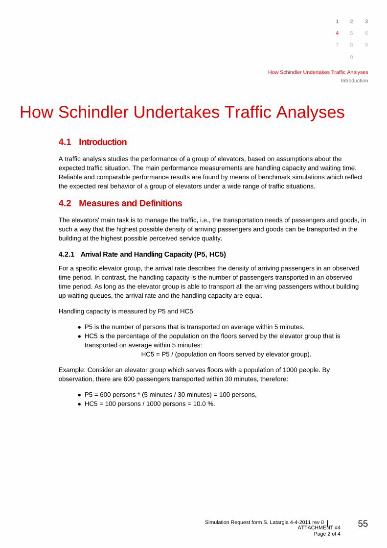
How Schindler Undertakes Traffic Analyses
4.1 Introduction
A traffic analysis studies the performance of a group of elevators, based on assumptions about the
expected traffic situation. The main performance measurements are handling capacity and waiting time.
Reliable and comparable performance results are found by means of benchmark simulations which reflect
the expected real behavior of a group of elevators under a wide range of traffic situations.
4.2 Measures and Definitions
The elevators' main task is to manage the traffic, i.e., the transportation needs of passengers and goods, in
such a way that the highest possible density of arriving passengers and goods can be transported in the
building at the highest possible perceived service quality.
4.2.1 Arrival Rate and Handling Capacity (P5, HC5)
For a specific elevator group, the arrival rate describes the density of arriving passengers in an observed
time period. In contrast, the handling capacity is the number of passengers transported in an observed
time period. As long as the elevator group is able to transport all the arriving passengers without building
up waiting queues, the arrival rate and the handling capacity are equal.
Handling capacity is measured by P5 and HC5:
P5 is the number of persons that is transported on average within 5 minutes.
HC5 is the percentage of the population on the floors served by the elevator group that is
transported on average within 5 minutes:
HC5 = P5 / (population on floors served by elevator group).
Example: Consider an elevator group which serves floors with a population of 1000 people. By
observation, there are 600 passengers transported within 30 minutes, therefore:
P5 = 600 persons * (5 minutes / 30 minutes) = 100 persons,
HC5 = 100 persons / 1000 persons = 10.0 %.
1 2 3
4 5 6
7 8 9
0
How Schindler Undertakes Traffic Analyses
Introduction
ATTACHMENT #4 Page 2 of 4
56Simulation Request form S. Latargia 4-4-2011 rev 0
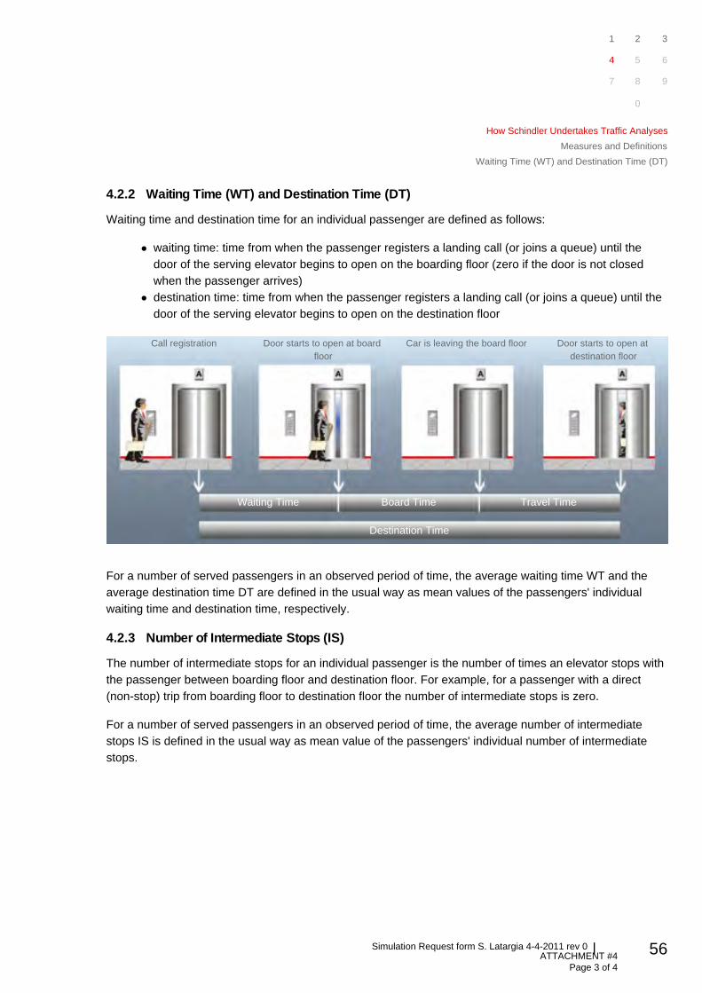
4.2.2 Waiting Time (WT) and Destination Time (DT)
Waiting time and destination time for an individual passenger are defined as follows:
waiting time: time from when the passenger registers a landing call (or joins a queue) until the
door of the serving elevator begins to open on the boarding floor (zero if the door is not closed
when the passenger arrives)
destination time: time from when the passenger registers a landing call (or joins a queue) until the
door of the serving elevator begins to open on the destination floor
Call registration Door starts to open at board
floor
Car is leaving the board floor Door starts to open at
destination floor
Waiting Time Board Time Travel Time
Destination Time
For a number of served passengers in an observed period of time, the average waiting time WT and the
average destination time DT are defined in the usual way as mean values of the passengers' individual
waiting time and destination time, respectively.
4.2.3 Number of Intermediate Stops (IS)
The number of intermediate stops for an individual passenger is the number of times an elevator stops with
the passenger between boarding floor and destination floor. For example, for a passenger with a direct
(non-stop) trip from boarding floor to destination floor the number of intermediate stops is zero.
For a number of served passengers in an observed period of time, the average number of intermediate
stops IS is defined in the usual way as mean value of the passengers' individual number of intermediate
stops.
1 2 3
4 5 6
7 8 9
0
How Schindler Undertakes Traffic Analyses
Measures and Definitions
Waiting Time (WT) and Destination Time (DT)
ATTACHMENT #4 Page 3 of 4
57Simulation Request form S. Latargia 4-4-2011 rev 0
4.3 Methods of Traffic Analysis
A traffic analysis should cover a variety of important traffic situations, especially when planning new
buildings. Reported values should be as reliable and comparable as possible. However, performance
values depend on the methods of the traffic analysis and the basic traffic assumptions.
4.3.1 Simulation vs. calculation methods
In simulation methods, a real passenger flow is being replaced by a virtual one, which was created with the
help of a random generator and loaded into the same control algorithm as used in a real elevator
controller. Thus the results can be measured under different traffic conditions and reflect the expected
reality to a very large extent.
In contrast, calculation methods are based on formulas which only cover a very limited range of traffic
situations (usually, only up-peak traffic). The formulas reflect theoretical assumptions rather than a realistic
behavior of elevator groups, and results are usually too optimistic. Therefore, calculation results should not
be compared with simulation results.
Schindler Traffic Analysis Reports are based on simulations in order that the reported results are the most
reliable and realistic achievable.
4.3.2 Wide Range of Traffic Assumptions
The traffic flow in a building keeps changing all the time; no two days are the same. As a rule, traffic
depends on many factors (such as location of building, tenant structure, etc.) and may vary considerably
during operation of the building. A traffic analysis should take such factors into consideration and try as far
as possible to cover future traffic situations.
In a complex building, a single traffic assumption is not sufficient. E.g., it is not sufficient to apply a traffic
pattern measured in some other existing building for the design of a new building. In particular, the limits of
the handling capacity of the elevators cannot be found by such "spot light" examinations.
Predictions about the range of handling capacity of an elevator group can only be made by actually
simulating a wide range of traffic situations. A benchmark method applies a reference traffic situation from
low to very high traffic intensity; by this, the limits of the elevators' handling capacity can be detected.
Schindler uses a benchmark method which gives a neutral system assessment.
Schindler Traffic Analysis Reports are based on different traffic situations (see Section 2) tested by
benchmark methods. This ensures that the traffic analysis covers a full range of applications and reports
reliable and comparable performance predictions.
1 2 3
4 5 6
7 8 9
0
How Schindler Undertakes Traffic Analyses
Methods of Traffic Analysis
Simulation vs. calculation methods
ATTACHMENT #4 Page 4 of 4
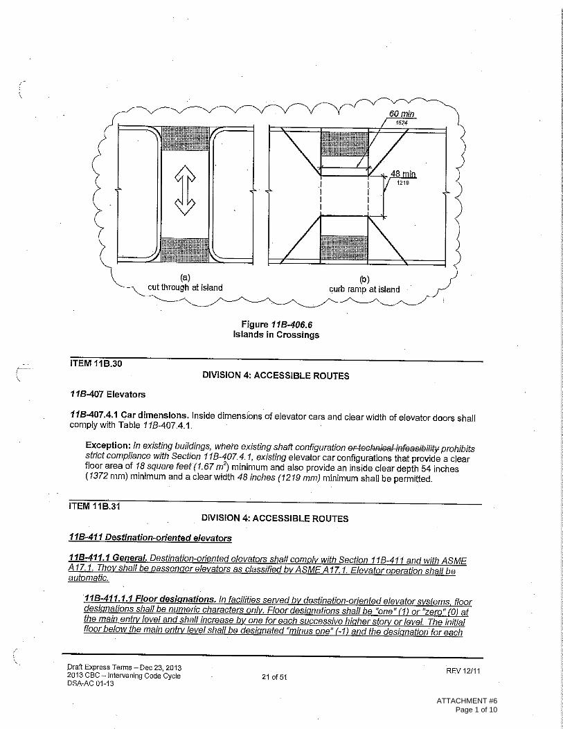
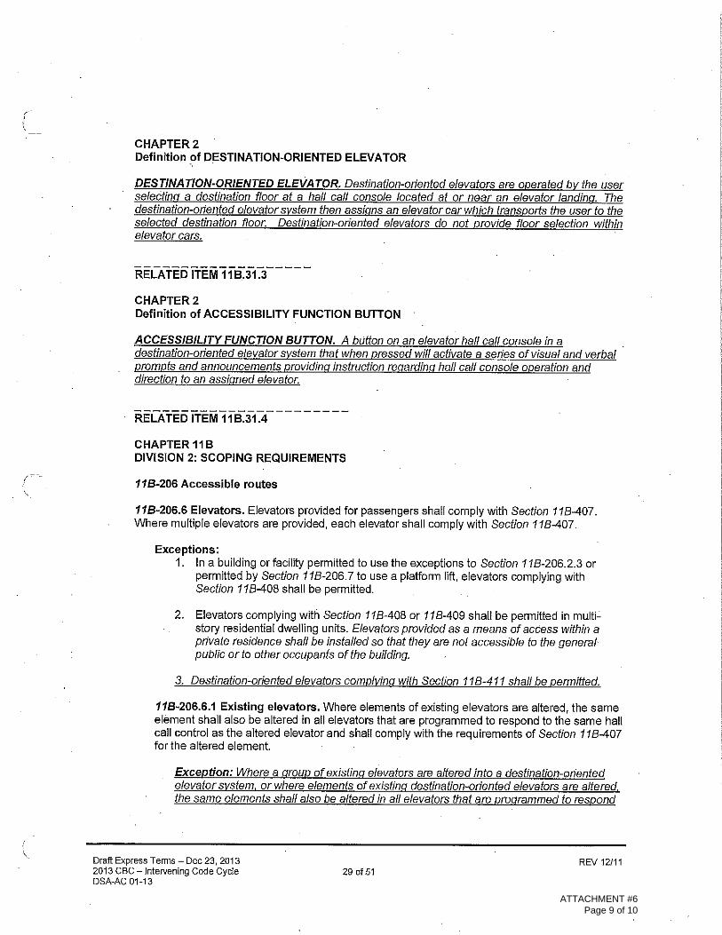
407 Elevators
This document is a draft proposal for expanded accessibility requirements for destination dispatch (destination-oriented) elevators. In accordance with NEII® policy it is based on the national consensus standard ICC/ANSI A117.1-2009, and incorporates the numbering and format of that standard.
This draft is not in precise legislative format as some of the existing standard’s text that does not apply to destination dispatch systems has been removed and not displayed in strikeout. For those sections where all of the text was deleted, the term “Reserved” is used to maintain the standard’s existing numbering system.
New requirements are derived from proposals to the A117 Committee that were considered by the NEII® Central Code Committee, provisions of the San Francisco Administrative Bulletin AB-090 on Destination-Based Elevator Control Systems, and comments by NEII® representatives on that Administrative Bulletin.
407.1 General. Elevators shall comply with Section 407 and ASME A17.1/CSA B44 listed in Section 105.2.5. Elevators shall be passenger elevators as classified by ASME A17.1/CSA B44. Elevator operation shall be automatic.
Existing A117.1 text.
407.2 Elevator Landing Requirements. Elevator landings shall comply with Section 407.2.
Existing A117.1 text.
407.2.1 Call Controls Interface Consoles. Where elevator call buttons or keypads car control interface consoles are provided, they shall comply with Sections 407.2.1 and 309.4. Call buttons shall be raised or flush. Objects beneath hall call buttons shall protrude 1 inch (25 mm) maximum.
San Francisco refers to “keypad consoles”. This is expanded to “interface consoles” to accommodate provisions for touch-screen displays.
407.2.1.1 Height. Call buttons and keypads shall be located within one of the reach ranges specified in Section 308, measured to the centerline of the highest operable part.
Existing A117.1 text.
ATTACHMENT #5 Page 1 of 13
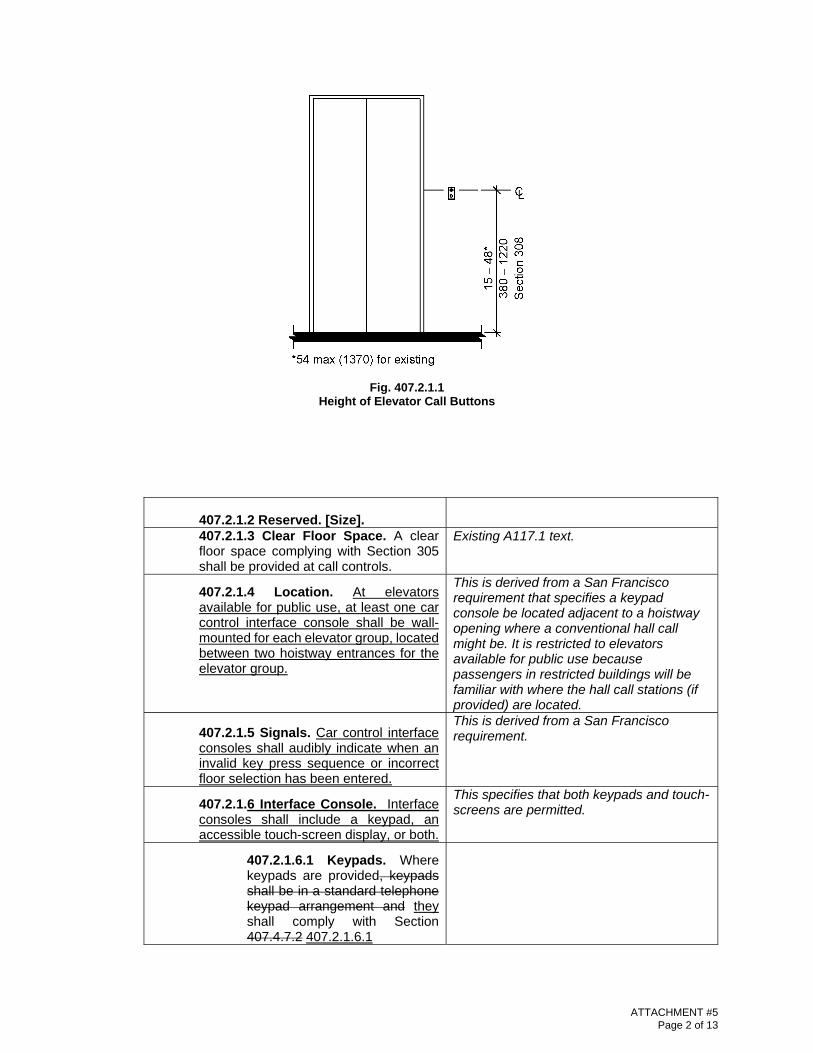
Fig. 407.2.1.1 Height of Elevator Call Buttons
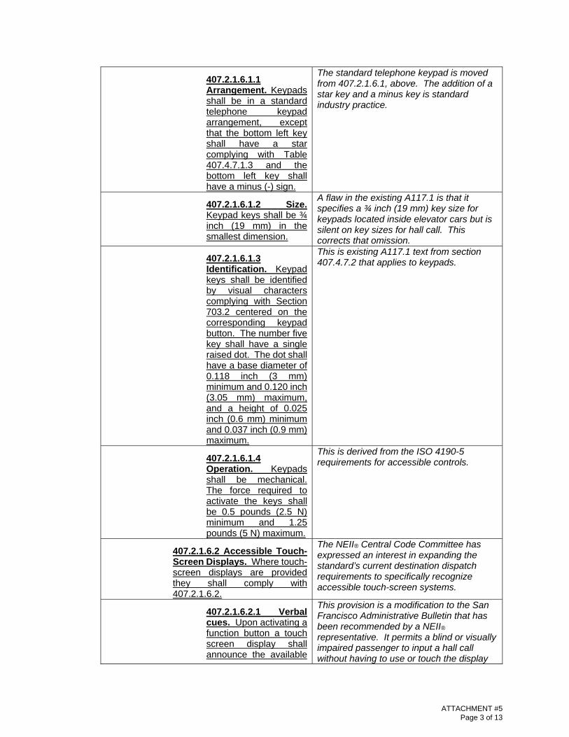
407.2.1.2 Reserved. [Size]. 407.2.1.3 Clear Floor Space. A clear floor space complying with Section 305 shall be provided at call controls.
Existing A117.1 text.
407.2.1.4 Location. At elevators available for public use, at least one car control interface console shall be wall-mounted for each elevator group, located between two hoistway entrances for the elevator group.
This is derived from a San Francisco requirement that specifies a keypad console be located adjacent to a hoistway opening where a conventional hall call might be. It is restricted to elevators available for public use because passengers in restricted buildings will be familiar with where the hall call stations (if provided) are located.
407.2.1.5 Signals. Car control interface consoles shall audibly indicate when an invalid key press sequence or incorrect floor selection has been entered.
This is derived from a San Francisco requirement.
407.2.1.6 Interface Console. Interface consoles shall include a keypad, an accessible touch-screen display, or both.
This specifies that both keypads and touch-screens are permitted.
407.2.1.6.1 Keypads. Where keypads are provided, keypads shall be in a standard telephone keypad arrangement and they shall comply with Section 407.4.7.2 407.2.1.6.1
ATTACHMENT #5 Page 2 of 13
407.2.1.6.1.1 Arrangement. Keypads shall be in a standard telephone keypad arrangement, except that the bottom left key shall have a star complying with Table 407.4.7.1.3 and the bottom left key shall have a minus (-) sign.
The standard telephone keypad is moved from 407.2.1.6.1, above. The addition of a star key and a minus key is standard industry practice.
407.2.1.6.1.2 Size. Keypad keys shall be ¾ inch (19 mm) in the smallest dimension.
A flaw in the existing A117.1 is that it specifies a ¾ inch (19 mm) key size for keypads located inside elevator cars but is silent on key sizes for hall call. This corrects that omission.
407.2.1.6.1.3 Identification. Keypad keys shall be identified by visual characters complying with Section 703.2 centered on the corresponding keypad button. The number five key shall have a single raised dot. The dot shall have a base diameter of 0.118 inch (3 mm) minimum and 0.120 inch (3.05 mm) maximum, and a height of 0.025 inch (0.6 mm) minimum and 0.037 inch (0.9 mm) maximum.
This is existing A117.1 text from section 407.4.7.2 that applies to keypads.
407.2.1.6.1.4 Operation. Keypads shall be mechanical. The force required to activate the keys shall be 0.5 pounds (2.5 N) minimum and 1.25 pounds (5 N) maximum.
This is derived from the ISO 4190-5 requirements for accessible controls.
407.2.1.6.2 Accessible Touch-Screen Displays. Where touch-screen displays are provided they shall comply with 407.2.1.6.2.
The NEII® Central Code Committee has expressed an interest in expanding the standard’s current destination dispatch requirements to specifically recognize accessible touch-screen systems.
407.2.1.6.2.1 Verbal cues. Upon activating a function button a touch screen display shall announce the available
This provision is a modification to the San Francisco Administrative Bulletin that has been recommended by a NEII® representative. It permits a blind or visually impaired passenger to input a hall call without having to use or touch the display
ATTACHMENT #5 Page 3 of 13

destination floors in ascending order. The touch screen shall indicate that pressing the function button a second time when the desired destination floor is announced will register the call. Requiring the touching of specific controls on a screen to make a floor selection shall not be permitted when a function key has been activated.
screen.
407.2.1.7 Destination-oriented Elevator Signals. Destination-oriented elevators shall be provided with a visible signal and audible tones and verbal announcements to indicate which car is responding to a call. The audible tone and verbal announcement shall be activated by pressing a function button. The function button shall be identified by the International Symbol for Accessibility and a raised indication. The International Symbol for Accessibility, complying with Section 703.6.3.1, shall be 5/8 inch (16 mm) in height and be a visual character complying with Section 703.2. The indication shall be three raised dots, spaced 1/4 inch (6.4 mm) at base diameter, in the form of an equilateral triangle. The function button shall be located immediately below the keypad arrangement or floor buttons.
Existing A117.1 text. It would make sense to place the Function Button in a more prominent place in an editorial revision of this draft, as the function button serves as the “portal” to all of the accessibility functions of a destination dispatch system. Whether a hall call is placed with a traditional mechanical keypad or an accessible touch-screen with voice cues, the user needs to know that every destination system he encounters will have a function key to guide his use of the system.
ATTACHMENT #5 Page 4 of 13
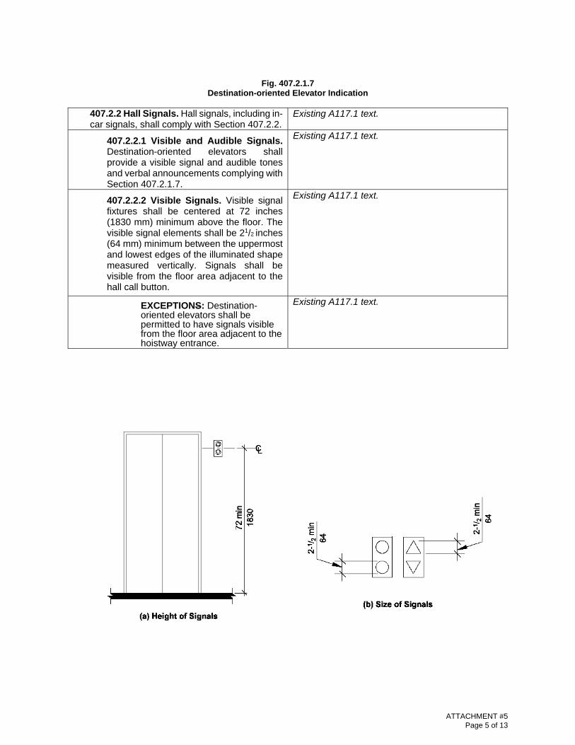
Fig. 407.2.1.7
Destination-oriented Elevator Indication
407.2.2 Hall Signals. Hall signals, including in-car signals, shall comply with Section 407.2.2.
Existing A117.1 text.
407.2.2.1 Visible and Audible Signals. Destination-oriented elevators shall provide a visible signal and audible tones and verbal announcements complying with Section 407.2.1.7.
Existing A117.1 text.
407.2.2.2 Visible Signals. Visible signal fixtures shall be centered at 72 inches (1830 mm) minimum above the floor. The visible signal elements shall be 21/2 inches (64 mm) minimum between the uppermost and lowest edges of the illuminated shape measured vertically. Signals shall be visible from the floor area adjacent to the hall call button.
Existing A117.1 text.
EXCEPTIONS: Destination-oriented elevators shall be permitted to have signals visible from the floor area adjacent to the hoistway entrance.
Existing A117.1 text.
ATTACHMENT #5 Page 5 of 13

Fig. 407.2.2.2 Elevator Visible Signals
407.2.2.3 Audible Signals. Destination-oriented elevators provide an audible tone and verbal announcement that is the same as those given at the call button or call button keypad.
Existing A117.1 text.
407.2.2.4 Differentiation. Each destina-tion-oriented elevator in a bank of elevators shall have audible and visible means for differentiation.
Existing A117.1 text.
407.2.3 Hoistway Signs. Signs at elevator hoistways shall comply with Section 407.2.3.
Existing A117.1 text.
407.2.3.1 Floor Designation. Floor designations shall be provided in raised characters and braille complying with Sections 703.3 and 703.4. Raised characters shall be 2 inches (51 mm) minimum in height. Floor designations shall be located on both jambs of elevator hoistway entrances. A raised star shall be provided on both jambs at the main entry level.
Existing A117.1 text.
Fig. 407.2.3.1
Floor Designation
407.2.3.2 Car Identification. Destination-ori-ented elevators shall provide car identification in raised characters and braille complying with Sections 703.3 and 703.4. Raised characters
Existing A117.1 text.
ATTACHMENT #5 Page 6 of 13

shall be 2 inches (51 mm) minimum in height. Car identifications shall be located on both jambs of the hoistway immediately below the floor designation.
Fig. 407.2.3.2
Destination-oriented Elevator Car Identification
407.2.4 Reserved. [Destination Signs] Existing A117.1 text provides an exception to this requirement for destination dispatch systems.
407.3 Elevator Door Requirements. Hoistway and elevator car doors shall comply with Section 407.3.
Existing A117.1 text.
407.3.1 Type. Elevator doors shall be horizontal sliding type. Car gates shall be prohibited.
Existing A117.1 text.
407.3.2 Operation. Elevator hoistway and car doors shall open and close automatically.
Existing A117.1 text.
407.3.3 Reopening Device. Elevator doors shall be provided with a reopening device complying with Section 407.3.3 that shall stop and reopen a car door and hoistway door automatically if the door becomes obstructed by an object or person.
Existing A117.1 text.
407.3.3.1 Height. The reopening device shall be activated by sensing an obstruction passing through the opening at 5 inches (125 mm) nominal and 29 inches (735 mm) nominal above the floor.
Existing A117.1 text.
407.3.3.2 Contact. The reopening device shall not require physical contact
Existing A117.1 text.
ATTACHMENT #5 Page 7 of 13

to be activated, although contact shall be permitted before the door reverses.
407.3.3.3 Duration. The reopening device shall remain effective for 20 seconds minimum.
Existing A117.1 text.
407.3.4 Reserved. [Door and Signal Timing]
407.3.5 Door Delay. Elevator doors shall remain fully open in response to a car call for 3 seconds minimum.
Existing A117.1 text.
407.3.6 Width. Elevator door clear opening width shall comply with Table 407.4.1.
Existing A117.1 text.
407.4 Elevator Car Requirements. Elevator cars shall comply with Section 407.4.
Existing A117.1 text.
407.4.1 Inside Dimensions. Inside dimensions of elevator cars shall comply with Table 407.4.1
Existing A117.1 text.
.
Table 407.4.1—Minimum Dimensions of Elevator Cars
Door Location
Door Clear Opening Width
Inside Car, Side toSide
Inside Car, BackWall to Front Return Inside Car, Back
Wall to Inside Face of Door
Centered 42 inches (1065 mm)
80 inches (2030 mm)
51 inches (1295 mm)
54 inches (1370 mm)
Side (Off Center)
36 inches (915 mm)1
68 inches (1725 mm)
51 inches (1295 mm)
54 inches (1370 mm)
Any 36 inches (915 mm)1
54 inches (1370 mm)
80 inches (2030 mm)
80 inches (2030 mm)
Any 36 inches (915 mm)1
60 inches (1525 mm)2
60 inches (1525 mm)2
60 inches (1525 mm)2
1A tolerance of minus5/8 inch (16 mm) is permitted. 2Other car configurations that provide a 36-inch (915mm) door clear opening width and a turning space complying with Section 304 with the door closed are permitted.
ATTACHMENT #5 Page 8 of 13

Fig. 407.4.1 Inside Dimensions of Elevator Cars
407.4.2 Floor Surfaces. Floor surfaces in elevator cars shall comply with Section 302.
Existing A117.1 text.
407.4.3 Platform to Hoistway Clearance. The clearance between the car platform sill and the edge of any hoistway landing shall comply with ASME A17.1/CSA B44 listed in Section 105.2.5.
Existing A117.1 text.
407.4.4 Leveling. Each car shall automatically stop and maintain position at floor landings within a tolerance of 1/2 inch (13
Existing A117.1 text.
ATTACHMENT #5 Page 9 of 13
mm) under rated loading to zero loading conditions. 407.4.5 Illumination. The level of illumination at the car controls, platform, car threshold and car landing sill shall comply with ASME A17.1/CSA B44 listed in Section 105.2.5.
Existing A117.1 text.
407.4.6 Elevator Car Controls. Where pro-vided, elevator car controls shall comply with Sections 407.4.6 and 309.
Existing A117.1 text.
407.4.6.1 Location. Controls shall be located within one of the reach ranges specified in Section 308.
Existing A117.1 text.
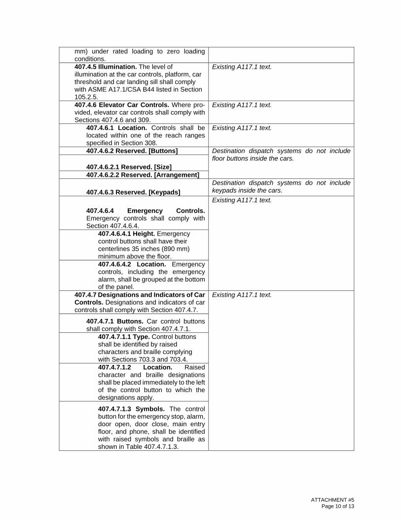
407.4.6.2 Reserved. [Buttons] Destination dispatch systems do not include floor buttons inside the cars.
407.4.6.2.1 Reserved. [Size] 407.4.6.2.2 Reserved. [Arrangement]
407.4.6.3 Reserved. [Keypads]
Destination dispatch systems do not include keypads inside the cars.
407.4.6.4 Emergency Controls. Emergency controls shall comply with Section 407.4.6.4.
Existing A117.1 text.
407.4.6.4.1 Height. Emergency control buttons shall have their centerlines 35 inches (890 mm) minimum above the floor. 407.4.6.4.2 Location. Emergency controls, including the emergency alarm, shall be grouped at the bottom of the panel.
407.4.7 Designations and Indicators of Car Controls. Designations and indicators of car controls shall comply with Section 407.4.7.
Existing A117.1 text.
407.4.7.1 Buttons. Car control buttons shall comply with Section 407.4.7.1.
407.4.7.1.1 Type. Control buttons shall be identified by raised characters and braille complying with Sections 703.3 and 703.4. 407.4.7.1.2 Location. Raised character and braille designations shall be placed immediately to the left of the control button to which the designations apply.
407.4.7.1.3 Symbols. The control button for the emergency stop, alarm, door open, door close, main entry floor, and phone, shall be identified with raised symbols and braille as shown in Table 407.4.7.1.3.
ATTACHMENT #5 Page 10 of 13
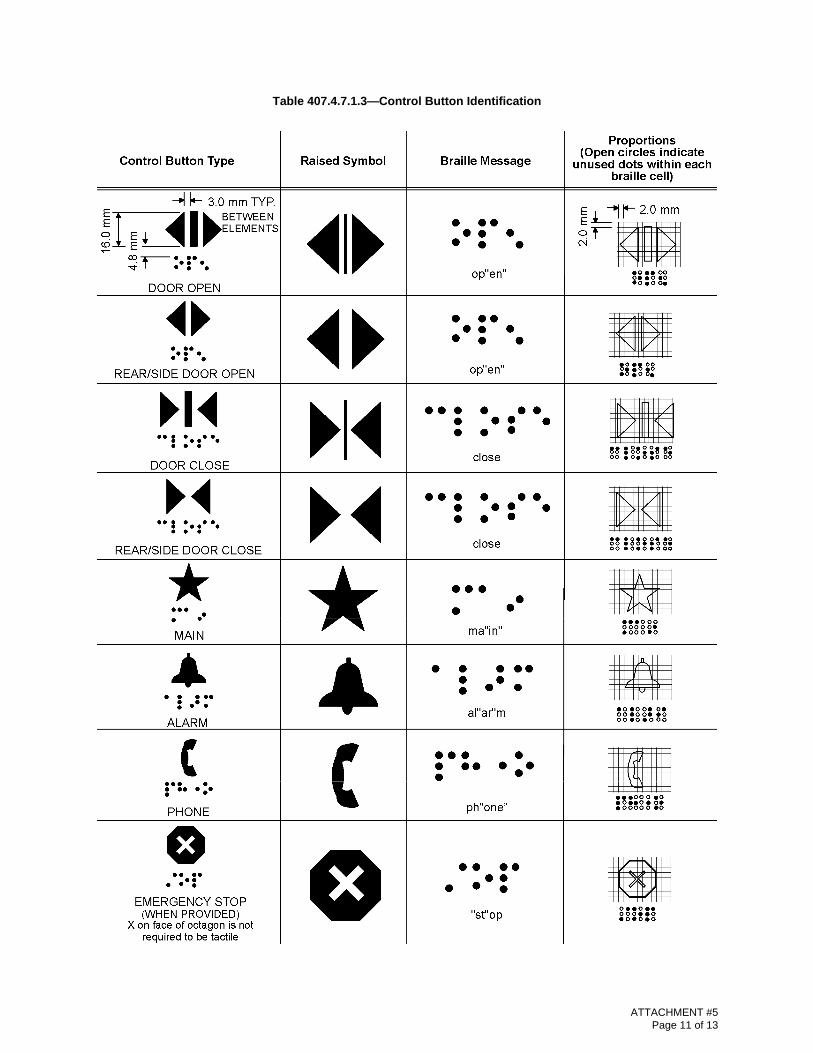
Table 407.4.7.1.3—Control Button Identification
ATTACHMENT #5 Page 11 of 13
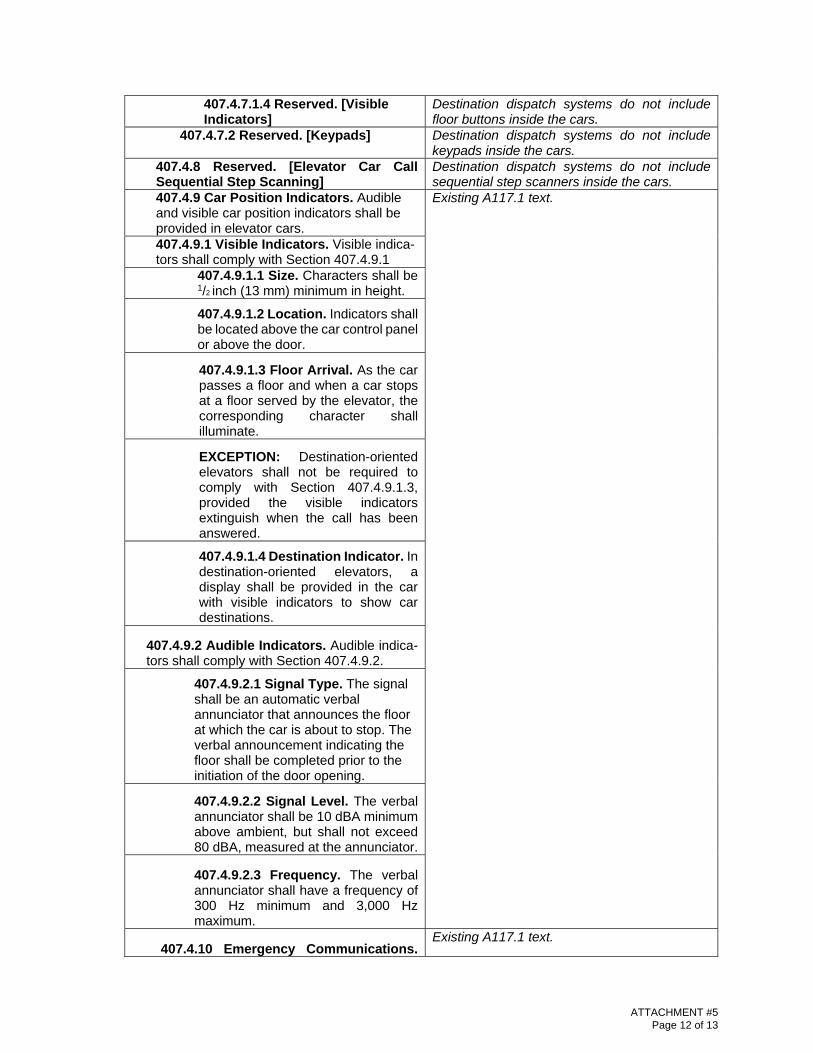
407.4.7.1.4 Reserved. [Visible Indicators]
Destination dispatch systems do not include floor buttons inside the cars.
407.4.7.2 Reserved. [Keypads] Destination dispatch systems do not include keypads inside the cars.
407.4.8 Reserved. [Elevator Car Call Sequential Step Scanning]
Destination dispatch systems do not include sequential step scanners inside the cars.
407.4.9 Car Position Indicators. Audible and visible car position indicators shall be provided in elevator cars.
Existing A117.1 text.
407.4.9.1 Visible Indicators. Visible indica-tors shall comply with Section 407.4.9.1
407.4.9.1.1 Size. Characters shall be 1/2 inch (13 mm) minimum in height.
407.4.9.1.2 Location. Indicators shall be located above the car control panel or above the door.
407.4.9.1.3 Floor Arrival. As the car passes a floor and when a car stops at a floor served by the elevator, the corresponding character shall illuminate.
EXCEPTION: Destination-oriented elevators shall not be required to comply with Section 407.4.9.1.3, provided the visible indicators extinguish when the call has been answered.
407.4.9.1.4 Destination Indicator. In destination-oriented elevators, a display shall be provided in the car with visible indicators to show car destinations.
407.4.9.2 Audible Indicators. Audible indica-tors shall comply with Section 407.4.9.2.
407.4.9.2.1 Signal Type. The signal shall be an automatic verbal annunciator that announces the floor at which the car is about to stop. The verbal announcement indicating the floor shall be completed prior to the initiation of the door opening.
407.4.9.2.2 Signal Level. The verbal annunciator shall be 10 dBA minimum above ambient, but shall not exceed 80 dBA, measured at the annunciator.
407.4.9.2.3 Frequency. The verbal annunciator shall have a frequency of 300 Hz minimum and 3,000 Hz maximum.
407.4.10 Emergency Communications. Existing A117.1 text.
ATTACHMENT #5 Page 12 of 13
Emergency two-way communication systems between the elevator car and a point outside the hoistway shall comply with Section 407.4.10 and ASME A17.1/CSA B44 listed in Section 105.2.5.
407.4.10.1 Height. The highest operable part of a two-way communication system shall comply with Section 308.
407.4.10.2 Identification. Raised characters and braille complying with Sections 703.3 and 703.4 and raised symbols complying with Section 407.4.7.1.3 shall be provided adjacent to the device.
ATTACHMENT #5 Page 13 of 13
ATTACHMENT #6 Page 1 of 10
ATTACHMENT #6 Page 2 of 10

ATTACHMENT #6 Page 3 of 10

ATTACHMENT #6 Page 4 of 10
ATTACHMENT #6 Page 5 of 10

ATTACHMENT #6 Page 6 of 10

ATTACHMENT #6 Page 7 of 10

ATTACHMENT #6 Page 8 of 10
ATTACHMENT #6 Page 9 of 10

ATTACHMENT #6 Page 10 of 10
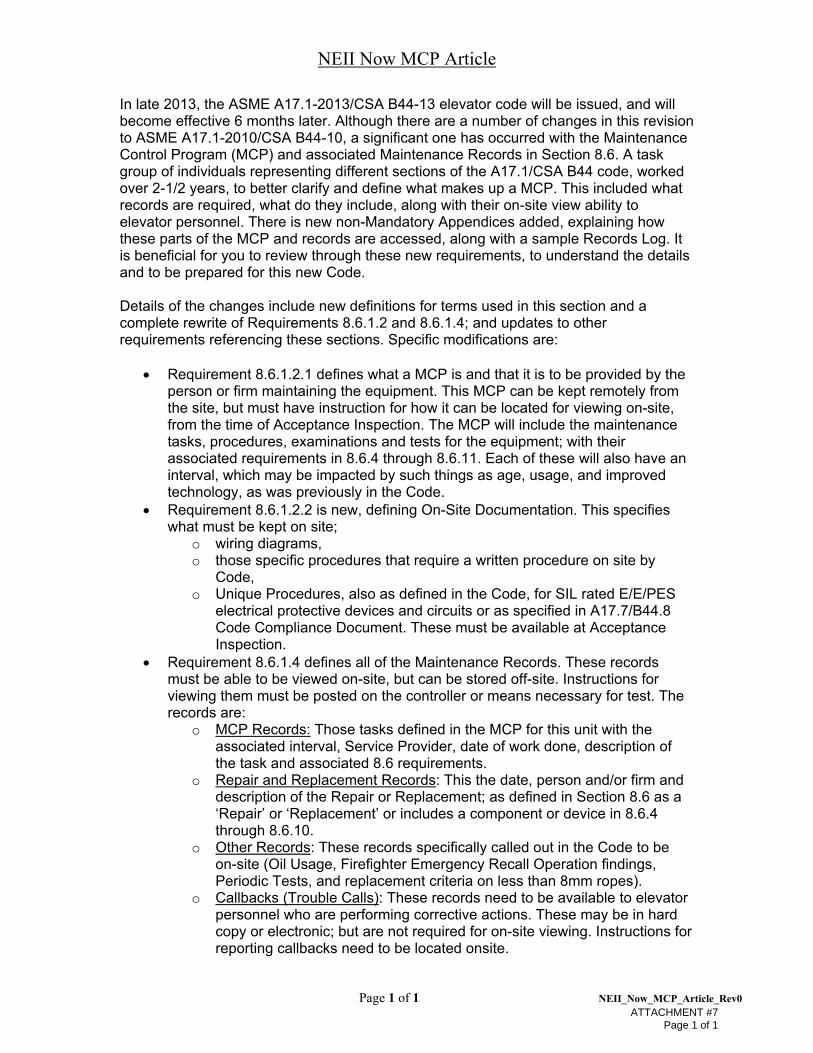
NEII Now MCP Article
Page 1 of 1 NEII_Now_MCP_Article_Rev0
In late 2013, the ASME A17.1-2013/CSA B44-13 elevator code will be issued, and will become effective 6 months later. Although there are a number of changes in this revision to ASME A17.1-2010/CSA B44-10, a significant one has occurred with the Maintenance Control Program (MCP) and associated Maintenance Records in Section 8.6. A task group of individuals representing different sections of the A17.1/CSA B44 code, worked over 2-1/2 years, to better clarify and define what makes up a MCP. This included what records are required, what do they include, along with their on-site view ability to elevator personnel. There is new non-Mandatory Appendices added, explaining how these parts of the MCP and records are accessed, along with a sample Records Log. It is beneficial for you to review through these new requirements, to understand the details and to be prepared for this new Code. Details of the changes include new definitions for terms used in this section and a complete rewrite of Requirements 8.6.1.2 and 8.6.1.4; and updates to other requirements referencing these sections. Specific modifications are:
Requirement 8.6.1.2.1 defines what a MCP is and that it is to be provided by the person or firm maintaining the equipment. This MCP can be kept remotely from the site, but must have instruction for how it can be located for viewing on-site, from the time of Acceptance Inspection. The MCP will include the maintenance tasks, procedures, examinations and tests for the equipment; with their associated requirements in 8.6.4 through 8.6.11. Each of these will also have an interval, which may be impacted by such things as age, usage, and improved technology, as was previously in the Code.
Requirement 8.6.1.2.2 is new, defining On-Site Documentation. This specifies what must be kept on site;
o wiring diagrams, o those specific procedures that require a written procedure on site by
Code, o Unique Procedures, also as defined in the Code, for SIL rated E/E/PES
electrical protective devices and circuits or as specified in A17.7/B44.8 Code Compliance Document. These must be available at Acceptance Inspection.
Requirement 8.6.1.4 defines all of the Maintenance Records. These records must be able to be viewed on-site, but can be stored off-site. Instructions for viewing them must be posted on the controller or means necessary for test. The records are:
o MCP Records: Those tasks defined in the MCP for this unit with the associated interval, Service Provider, date of work done, description of the task and associated 8.6 requirements.
o Repair and Replacement Records: This the date, person and/or firm and description of the Repair or Replacement; as defined in Section 8.6 as a ‘Repair’ or ‘Replacement’ or includes a component or device in 8.6.4 through 8.6.10.
o Other Records: These records specifically called out in the Code to be on-site (Oil Usage, Firefighter Emergency Recall Operation findings, Periodic Tests, and replacement criteria on less than 8mm ropes).
o Callbacks (Trouble Calls): These records need to be available to elevator personnel who are performing corrective actions. These may be in hard copy or electronic; but are not required for on-site viewing. Instructions for reporting callbacks need to be located onsite.
ATTACHMENT #7 Page 1 of 1
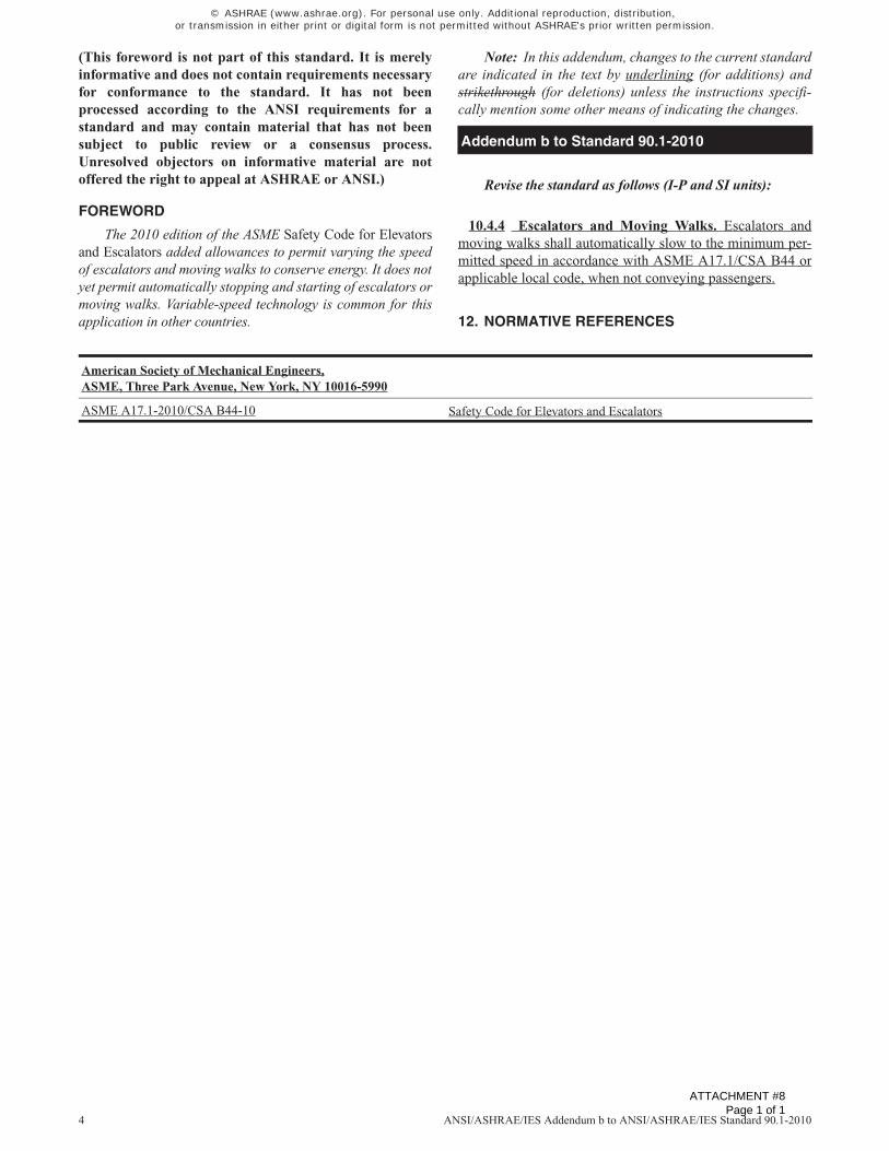
4 ANSI/ASHRAE/IES Addendum b to ANSI/ASHRAE/IES Standard 90.1-2010
(This foreword is not part of this standard. It is merelyinformative and does not contain requirements necessaryfor conformance to the standard. It has not beenprocessed according to the ANSI requirements for astandard and may contain material that has not beensubject to public review or a consensus process.Unresolved objectors on informative material are notoffered the right to appeal at ASHRAE or ANSI.)
FOREWORD
The 2010 edition of the ASME Safety Code for Elevatorsand Escalators added allowances to permit varying the speedof escalators and moving walks to conserve energy. It does notyet permit automatically stopping and starting of escalators ormoving walks. Variable-speed technology is common for thisapplication in other countries.
Note: In this addendum, changes to the current standardare indicated in the text by underlining (for additions) andstrikethrough (for deletions) unless the instructions specifi-cally mention some other means of indicating the changes.
Revise the standard as follows (I-P and SI units):
10.4.4 Escalators and Moving Walks. Escalators andmoving walks shall automatically slow to the minimum per-mitted speed in accordance with ASME A17.1/CSA B44 orapplicable local code, when not conveying passengers.
12. NORMATIVE REFERENCES
Addendum b to Standard 90.1-2010
American Society of Mechanical Engineers,ASME, Three Park Avenue, New York, NY 10016-5990
ASME A17.1-2010/CSA B44-10 Safety Code for Elevators and Escalators
© ASHRAE (www.ashrae.org). For personal use only. Additional reproduction, distribution, or transmission in either print or digital form is not permitted without ASHRAE's prior written permission.
ATTACHMENT #8 Page 1 of 1

ACE EE:: American Council for an [nergy-Effic1ent [conomy
April 7, 2014
Robert S. Caporale Editor/Sr. Vice President Elevator World 354 Morgan Avenue P.O. Box 6507 (36660) Mobile, AL
Dear Mr. Caporale:
52914th Street. N. W .. Suite 600 Washington. O.C. 20045 f<> 202.507.4000 o 202.429.2248 o www.aceee.org
Almost a decade ago, you were very helpful as we did research for our 2005 White Paper on Opportunities for Elevator Energy Efficiency Improvements., exploring opportunities for programs such as EnergyStar to encourage adoption of advanced technologies and practices. ACEEE has received funding to update and extend this work, with particular emphasis on new policy options. These include first inclusion of elevators in ANSI/ASHRAE/IESNA 90.1-2013, Energy Standard for Buildings Except Low-Rise Residential Buildings., EnergyStar, and electric utility incentive programs.
To make our work as robust as possible, we seek to engage the industry itself, those who know best what works, have thought about what could work, and are eager to explore new opportunities. We are not seeking additional funding, but we feel there are other ways Elevator World (and NEil, whom we are also contacting) could help us, for the benefit of the industry you serve. Here are some of our thoughts; and you may recognize other opportunities:
1. We want to form an Advisory Committee of leading manufacturers. We'll ask them individually for their ideas on important available and emerging technologies, and we'll ask them to review our draft report to assure that it meets the highest standards possible. We seek your help in developing contacts at the appropriate firms. We can start with Marketing Directors, or Government Affairs Directors, as long as they have the insights to find the appropriate representatives in their firms. Of course, we'd love to have you on this committee, too.
2. We'd like to provide you with a brief press release announcing the project, for publication as an item in the ELEV ATOR WORLD magazine, or such other distribution as you feel is quickest and works best for you. This assures that we reach industry people.
3. At the conclusion of the project this summer, we'll certainly provide a press release, can develop a blog post (or link to ours), or otherwise help you share our findings with your members.
We would appreciate the opportunity to discuss this with you or your staff this week, Tuesday, or Thursday, if at all possible. Please feel free to respond proactively to reach me.
Sincerely,
Harvey Sachs, Ph.D Senior Fellow, 703-848-8136, [email protected]
ATTACHMENT #9 Page 1 of 1
PERFORMANCE TERMINOLOGY MATRIX
22-Nov-11 Page 5 - 3 NEII-1 © 2000-2011, National Elevator Industry Inc., Salem, NY. NEII and NEII logo – Registered, U.S. Patent and Trademark Office.
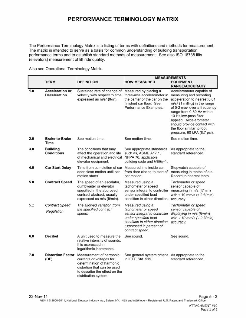
The Performance Terminology Matrix is a listing of terms with definitions and methods for measurement. The matrix is intended to serve as a basis for common understanding of building transportation performance terms and to establish standard methods of measurement. See also ISO 18738 lifts (elevators) measurement of lift ride quality. Also see Operational Terminology Matrix. MEASUREMENTS TERM DEFINITION HOW MEASURED EQUIPMENT,
RANGE/ACCURACY 1.0 Acceleration or
Deceleration Sustained rate of change of velocity with respect to time expressed as m/s² (ft/s²).
Measured by placing a three-axis accelerometer in the center of the car on the finished car floor. See Performance Examples.
Accelerometer capable of measuring and recording acceleration to nearest 0.01 m/s2 (1 milli-g) in the range of 0-2 m/s2 over a frequency range from 0-80 Hz with a 10 Hz low-pass filter applied. Accelerometer should provide contact with the floor similar to foot pressure, 60 kPA (8.7 psi).
2.0 Brake-to-Brake Time
See motion time. See motion time. See motion time.
3.0 Building Conditions
The conditions that may affect the operation and life of mechanical and electrical elevator equipment.
See appropriate standards such as, ASME A17.1, NFPA 70, applicable building code and NEII®–1.
As appropriate to the standard referenced.
4.0 Car Start Delay Time from completion of car door close motion until car motion starts.
Measured in s inside car from door closed to start of car motion.
Stopwatch capable of measuring in tenths of a s. Record to nearest tenth.
5.0 Contract Speed The speed of an escalator, dumbwaiter or elevator specified in the approved contract abstract, usually expressed as m/s (ft/min).
Measured using a tachometer or speed sensor integral to controller under specified load condition in either direction.
Tachometer or speed sensor capable of measuring in m/s (ft/min) with 10 mm/s ( 2 ft/min) accuracy.
5.1 Contract Speed
Regulation
The allowed variation from the specified contract speed.
Measured using a tachometer or speed sensor integral to controller under specified load condition in either direction. Expressed in percent of contract speed.
Tachometer or speed sensor capable of displaying in m/s (ft/min) with 10 mm/s ( 2 ft/min) accuracy.
6.0 Decibel A unit used to measure the relative intensity of sounds. It is expressed in logarithmic increments.
See sound. See sound.
7.0 Distortion Factor (DF)
Measurement of harmonic currents or voltages for determination of harmonic distortion that can be used to describe the effect on the distribution system.
See general system criteria in IEEE Std. 519.
As appropriate to the standard referenced.
ATTACHMENT #10 Page 1 of 9
PERFORMANCE TERMINOLOGY MATRIX
Page 5 – 4 22-Nov-11 NEII-1 © 2000-2011, National Elevator Industry Inc., Salem, NY. NEII and NEII logo – Registered, U.S. Patent and Trademark Office.
MEASUREMENTS TERM DEFINITION HOW MEASURED EQUIPMENT,
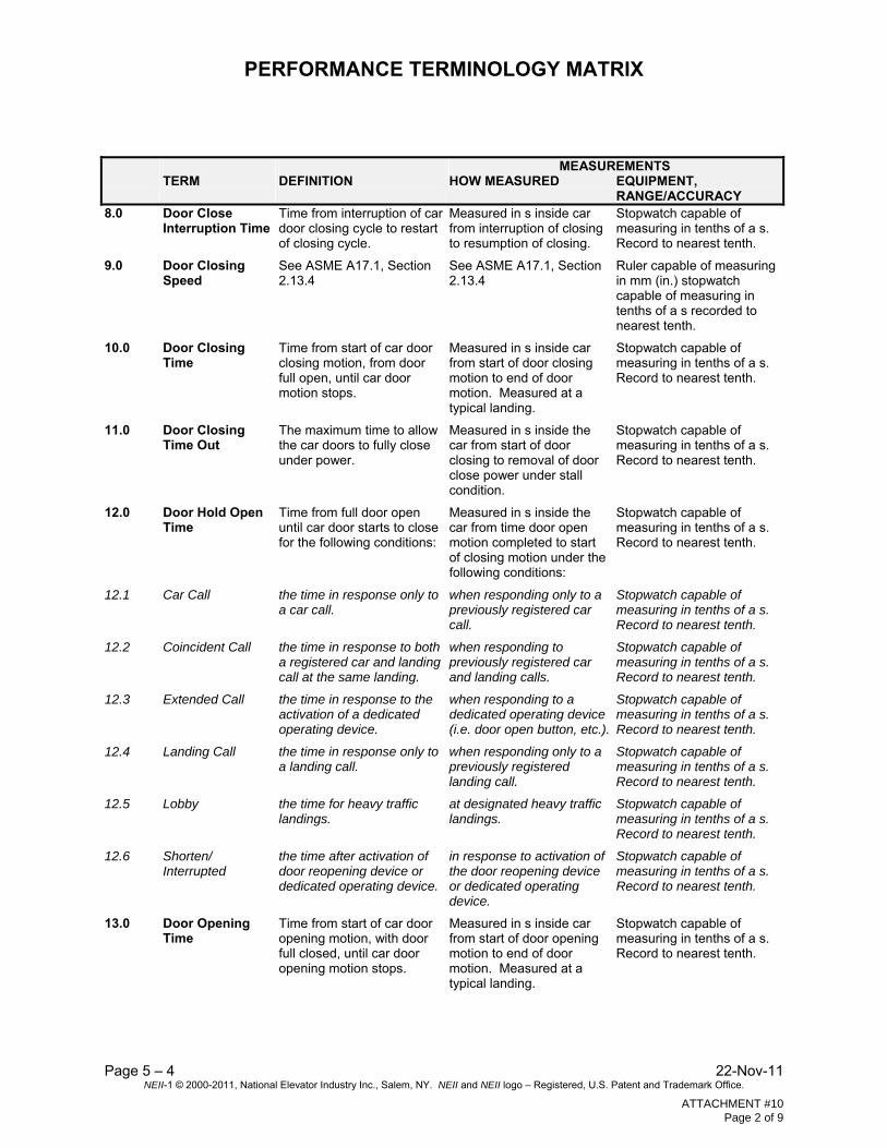
RANGE/ACCURACY 8.0 Door Close
Interruption Time Time from interruption of car door closing cycle to restart of closing cycle.
Measured in s inside car from interruption of closing to resumption of closing.
Stopwatch capable of measuring in tenths of a s. Record to nearest tenth.
9.0 Door Closing Speed
See ASME A17.1, Section 2.13.4
See ASME A17.1, Section 2.13.4
Ruler capable of measuring in mm (in.) stopwatch capable of measuring in tenths of a s recorded to nearest tenth.
10.0 Door Closing Time
Time from start of car door closing motion, from door full open, until car door motion stops.
Measured in s inside car from start of door closing motion to end of door motion. Measured at a typical landing.
Stopwatch capable of measuring in tenths of a s. Record to nearest tenth.
11.0 Door Closing Time Out
The maximum time to allow the car doors to fully close under power.
Measured in s inside the car from start of door closing to removal of door close power under stall condition.
Stopwatch capable of measuring in tenths of a s. Record to nearest tenth.
12.0 Door Hold Open Time
Time from full door open until car door starts to close for the following conditions:
Measured in s inside the car from time door open motion completed to start of closing motion under the following conditions:
Stopwatch capable of measuring in tenths of a s. Record to nearest tenth.
12.1 Car Call the time in response only to a car call.
when responding only to a previously registered car call.
Stopwatch capable of measuring in tenths of a s. Record to nearest tenth.
12.2 Coincident Call the time in response to both a registered car and landing call at the same landing.
when responding to previously registered car and landing calls.
Stopwatch capable of measuring in tenths of a s. Record to nearest tenth.
12.3 Extended Call the time in response to the activation of a dedicated operating device.
when responding to a dedicated operating device (i.e. door open button, etc.).
Stopwatch capable of measuring in tenths of a s. Record to nearest tenth.
12.4 Landing Call the time in response only to a landing call.
when responding only to a previously registered landing call.
Stopwatch capable of measuring in tenths of a s. Record to nearest tenth.
12.5 Lobby the time for heavy traffic landings.
at designated heavy traffic landings.
Stopwatch capable of measuring in tenths of a s. Record to nearest tenth.
12.6 Shorten/ Interrupted
the time after activation of door reopening device or dedicated operating device.
in response to activation of the door reopening device or dedicated operating device.
Stopwatch capable of measuring in tenths of a s. Record to nearest tenth.
13.0 Door Opening Time
Time from start of car door opening motion, with door full closed, until car door opening motion stops.
Measured in s inside car from start of door opening motion to end of door motion. Measured at a typical landing.
Stopwatch capable of measuring in tenths of a s. Record to nearest tenth.
ATTACHMENT #10 Page 2 of 9

PERFORMANCE TERMINOLOGY MATRIX
22-Nov-11 Page 5 - 5 NEII-1 © 2000-2011, National Elevator Industry Inc., Salem, NY. NEII and NEII logo – Registered, U.S. Patent and Trademark Office.
MEASUREMENTS TERM DEFINITION HOW MEASURED EQUIPMENT,
RANGE/ACCURACY 13.1 Door Opening
Time, Nominal Time from start of car door opening motion to 50mm (2 in.) from clear door opening.
Measured in s inside car from start of door(s) open motion to 50 mm (2 in.) from extreme door(s) open position. Measured at a typical landing.
Stopwatch capable of measuring in tenths of a s. Record to nearest tenth.
14.0 Door, Non-Contact Reopening Device Disconnect Time
Time before non-contact door reopening device(s) are deactivated after detection of interference.
Disable nudging feature if provided. Measured in s inside the car from the start of door closing and the continuous activation of the reopening device to start of door closing.
Stopwatch capable of measuring in tenths of a s. Record to nearest tenth.
15.0 Door Pre-Opening, Maximum Width
The maximum allowable width the doors can be open with the car in motion within the door pre-opening zone on initial approach to the landing.
Measured inside the car by marking the maximum allowable distance on the car sill. Verify that position of doors does not exceed distance on initial approach to landing.
Ruler capable of measuring in mm (in.).
16.0 Door Pre-Opening Zone
The maximum allowable distance the car can be from the landing sill when the door(s) start to physically move in the open direction.
See ASME A17.1 requirements for leveling and unlocking zones.
Ruler capable of measuring in mm (in.).
17.0 Duty Cycle, Elevator and Escalator
A statement of loading and duration of various sequences of start, run and idle time under which the equipment operates.
Calculate the percentage of motion time related to a time period.
As required.
18.0 Duty Factor A parameter defining the "run" time duration at rated load for a given time period.
For elevator systems a typical value of 35% "run" time for one-hour time period. Used for calculation of heat emission.
Not applicable.
19.0 Dwell on Start See car start delay. See car start delay. See car start delay.
20.0 Hall Call Registration Time, Average
Average time of hall push button illumination after registration of landing calls.
An event recording instrument connected to each hall push button circuit to measure button illumination times over a designated survey period of 5 min or longer.
Event recording instrument capable of measuring in s, with appropriate interface.
NOTE: See system response time.
ATTACHMENT #10 Page 3 of 9
PERFORMANCE TERMINOLOGY MATRIX
Page 5 – 6 22-Nov-11 NEII-1 © 2000-2011, National Elevator Industry Inc., Salem, NY. NEII and NEII logo – Registered, U.S. Patent and Trademark Office.
MEASUREMENTS TERM DEFINITION HOW MEASURED EQUIPMENT,
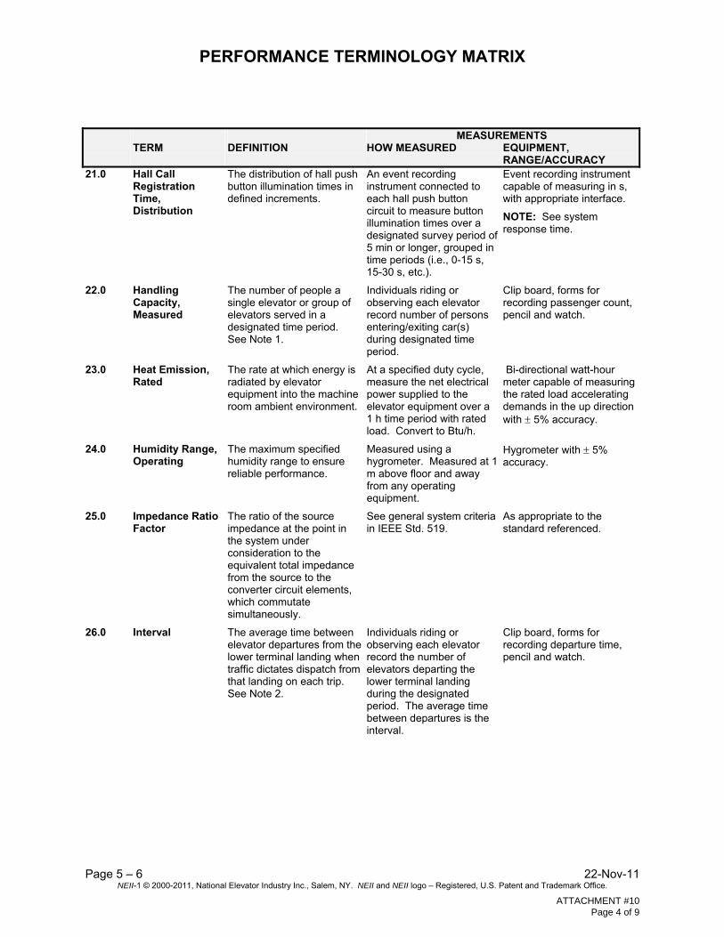
RANGE/ACCURACY 21.0 Hall Call
Registration Time, Distribution
The distribution of hall push button illumination times in defined increments.
An event recording instrument connected to each hall push button circuit to measure button illumination times over a designated survey period of 5 min or longer, grouped in time periods (i.e., 0-15 s, 15-30 s, etc.).
Event recording instrument capable of measuring in s, with appropriate interface.
NOTE: See system response time.
22.0 Handling Capacity, Measured
The number of people a single elevator or group of elevators served in a designated time period. See Note 1.
Individuals riding or observing each elevator record number of persons entering/exiting car(s) during designated time period.
Clip board, forms for recording passenger count, pencil and watch.
23.0 Heat Emission, Rated
The rate at which energy is radiated by elevator equipment into the machine room ambient environment.
At a specified duty cycle, measure the net electrical power supplied to the elevator equipment over a 1 h time period with rated load. Convert to Btu/h.
Bi-directional watt-hour meter capable of measuring the rated load accelerating demands in the up direction with 5% accuracy.
24.0 Humidity Range, Operating
The maximum specified humidity range to ensure reliable performance.
Measured using a hygrometer. Measured at 1 m above floor and away from any operating equipment.
Hygrometer with 5% accuracy.
25.0 Impedance Ratio Factor
The ratio of the source impedance at the point in the system under consideration to the equivalent total impedance from the source to the converter circuit elements, which commutate simultaneously.
See general system criteria in IEEE Std. 519.
As appropriate to the standard referenced.
26.0 Interval The average time between elevator departures from the lower terminal landing when traffic dictates dispatch from that landing on each trip. See Note 2.
Individuals riding or observing each elevator record the number of elevators departing the lower terminal landing during the designated period. The average time between departures is the interval.
Clip board, forms for recording departure time, pencil and watch.
ATTACHMENT #10 Page 4 of 9

PERFORMANCE TERMINOLOGY MATRIX
22-Nov-11 Page 5 - 7 NEII-1 © 2000-2011, National Elevator Industry Inc., Salem, NY. NEII and NEII logo – Registered, U.S. Patent and Trademark Office.
MEASUREMENTS TERM DEFINITION HOW MEASURED EQUIPMENT,
RANGE/ACCURACY 27.0 Jerk Rate of change of
acceleration or deceleration with respect to time. A commonly used control parameter that should not be used as a measure of human perception or ride quality. See vibration, car.
Measured graphically or calculated. Measured graphically as the best fitting slope of the acceleration or deceleration recording. Calculated from acceleration using the maximum slope of the running least squares best fit line with a 0.5 s window. See Performance Examples.
Accelerometer capable of measuring and recording acceleration to nearest 0.01 m/s2 (1 milli-g) in the range of 0-2 m/s2 over a frequency range from 0-80 Hz with a 10 Hz low-pass filter applied.
28.0 Jitter See vibration, car. See vibration, car. See vibration, car.
29.0 Line Voltage Notch
The dip in the supply voltage waveform to a converter due to transfer of current within the power converter during a commutation interval.
See general system criteria in IEEE Std. 519.
As appropriate to the standard referenced.
30.0 Motion Time Time from start of car movement until car is stopped within a predetermined stopping zone.
Time measured from the first motion of the car to arrival of the car within a specified stopping zone. Measured at typical adjacent landings.
Stopwatch capable of measuring in tenths of a s. Record to nearest tenth.
31.0 Noise, Electrical Any random disturbance in an electric circuit which changes or interferes with the primary signal.
See general system criteria in IEEE Std. 519.
As appropriate to the standard referenced.
32.0 Noise, Mechanical
See sound. See sound. See sound.
33.0 Nominal Value The expected (stated) value of the measurement.
Instrument applicable for measurement being taken.
As appropriate.
34.0 Notification Time, Landing Call
Time from notification, at the landing, that the car is answering the landing call until the door(s) of that car start to close.
Measured at the landing from illumination of lantern and sounding of audible signal until door(s) start to close. See Note 3.
Stopwatch capable of measuring in tenths of a s. Record to nearest tenth.
35.0 Nudging An operational feature used to force door closing at reduced speed (kinetic energy) typically with an audible signal after a predetermined time.
See ASME A17.1 and definition of door nudging start time.
See door nudging start and closing time.
35.1 Door Nudging Start Time
Time for nudging to start after continuous activation of door reopening device.
Measured in s inside the car from the expiration of door opening time to start of nudging with the continuous activation of the door-reopening device.
Stopwatch capable of measuring in tenths of a s. Record to nearest tenth.
ATTACHMENT #10 Page 5 of 9
PERFORMANCE TERMINOLOGY MATRIX
Page 5 – 8 22-Nov-11 NEII-1 © 2000-2011, National Elevator Industry Inc., Salem, NY. NEII and NEII logo – Registered, U.S. Patent and Trademark Office.
MEASUREMENTS TERM DEFINITION HOW MEASURED EQUIPMENT,
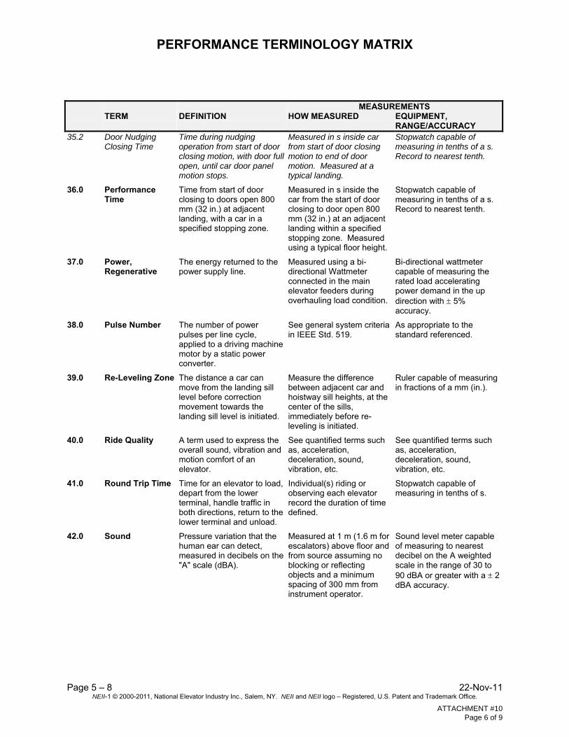
RANGE/ACCURACY 35.2 Door Nudging
Closing Time Time during nudging operation from start of door closing motion, with door full open, until car door panel motion stops.
Measured in s inside car from start of door closing motion to end of door motion. Measured at a typical landing.
Stopwatch capable of measuring in tenths of a s. Record to nearest tenth.
36.0 Performance Time
Time from start of door closing to doors open 800 mm (32 in.) at adjacent landing, with a car in a specified stopping zone.
Measured in s inside the car from the start of door closing to door open 800 mm (32 in.) at an adjacent landing within a specified stopping zone. Measured using a typical floor height.
Stopwatch capable of measuring in tenths of a s. Record to nearest tenth.
37.0 Power, Regenerative
The energy returned to the power supply line.
Measured using a bi-directional Wattmeter connected in the main elevator feeders during overhauling load condition.
Bi-directional wattmeter capable of measuring the rated load accelerating power demand in the up direction with 5% accuracy.
38.0 Pulse Number The number of power pulses per line cycle, applied to a driving machine motor by a static power converter.
See general system criteria in IEEE Std. 519.
As appropriate to the standard referenced.
39.0 Re-Leveling Zone The distance a car can move from the landing sill level before correction movement towards the landing sill level is initiated.
Measure the difference between adjacent car and hoistway sill heights, at the center of the sills, immediately before re-leveling is initiated.
Ruler capable of measuring in fractions of a mm (in.).
40.0 Ride Quality A term used to express the overall sound, vibration and motion comfort of an elevator.
See quantified terms such as, acceleration, deceleration, sound, vibration, etc.
See quantified terms such as, acceleration, deceleration, sound, vibration, etc.
41.0 Round Trip Time Time for an elevator to load, depart from the lower terminal, handle traffic in both directions, return to the lower terminal and unload.
Individual(s) riding or observing each elevator record the duration of time defined.
Stopwatch capable of measuring in tenths of s.
42.0 Sound Pressure variation that the human ear can detect, measured in decibels on the "A" scale (dBA).
Measured at 1 m (1.6 m for escalators) above floor and from source assuming no blocking or reflecting objects and a minimum spacing of 300 mm from instrument operator.
Sound level meter capable of measuring to nearest decibel on the A weighted scale in the range of 30 to 90 dBA or greater with a 2 dBA accuracy.
ATTACHMENT #10 Page 6 of 9
PERFORMANCE TERMINOLOGY MATRIX
22-Nov-11 Page 5 - 9 NEII-1 © 2000-2011, National Elevator Industry Inc., Salem, NY. NEII and NEII logo – Registered, U.S. Patent and Trademark Office.
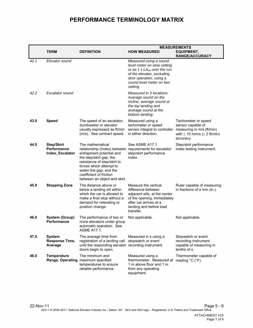
MEASUREMENTS TERM DEFINITION HOW MEASURED EQUIPMENT,
RANGE/ACCURACY 42.1 Elevator sound Measured using a sound
level meter on slow setting or as 1 s LAeq over the run of the elevator, excluding door operation, using a sound level meter on fast setting.
42.2 Escalator sound Measured in 3 locations: Average sound on the incline, average sound at the top landing and average sound at the bottom landing.
43.0 Speed The speed of an escalator, dumbwaiter or elevator usually expressed as ft/min (m/s). See contract speed.
Measured using a tachometer or speed sensor integral to controller in either direction.
Tachometer or speed sensor capable of measuring in m/s (ft/min) with 10 mm/s ( 2 ft/min) accuracy.
44.0 Step/Skirt Performance Index, Escalator
The mathematical relationship (Index) between entrapment potential and the step/skirt gap; the resistance of step/skirt to forces which attempt to widen the gap; and the coefficient of friction between an object and skirt.
See ASME A17.1 requirements for escalator step/skirt performance index.
Step/skirt performance index testing instrument.
45.0 Stopping Zone The distance above or below a landing sill within which the car is allowed to make a final stop without a demand for releveling or position change.
Measure the vertical difference between adjacent sills, at the center of the opening, immediately after car arrives at a landing and before load transfer.
Ruler capable of measuring in fractions of a mm (in.).
46.0 System (Group) Performance
The performance of two or more elevators under group automatic operation. See ASME A17.1.
Not applicable. Not applicable.
47.0 System Response Time, Average
The average time from registration of a landing call until the responding elevator doors begin to open.
Measured in s using a stopwatch or event recording instrument.
Stopwatch or event recording instrument capable of measuring in tenths of s.
48.0 Temperature Range, Operating
The minimum and maximum specified temperatures to ensure reliable performance.
Measured using a thermometer. Measured at 1 m above floor and 1 m from any operating equipment.
Thermometer capable of reading C (F).
ATTACHMENT #10 Page 7 of 9
PERFORMANCE TERMINOLOGY MATRIX
Page 5 – 10 22-Nov-11 NEII-1 © 2000-2011, National Elevator Industry Inc., Salem, NY. NEII and NEII logo – Registered, U.S. Patent and Trademark Office.
MEASUREMENTS TERM DEFINITION HOW MEASURED EQUIPMENT,
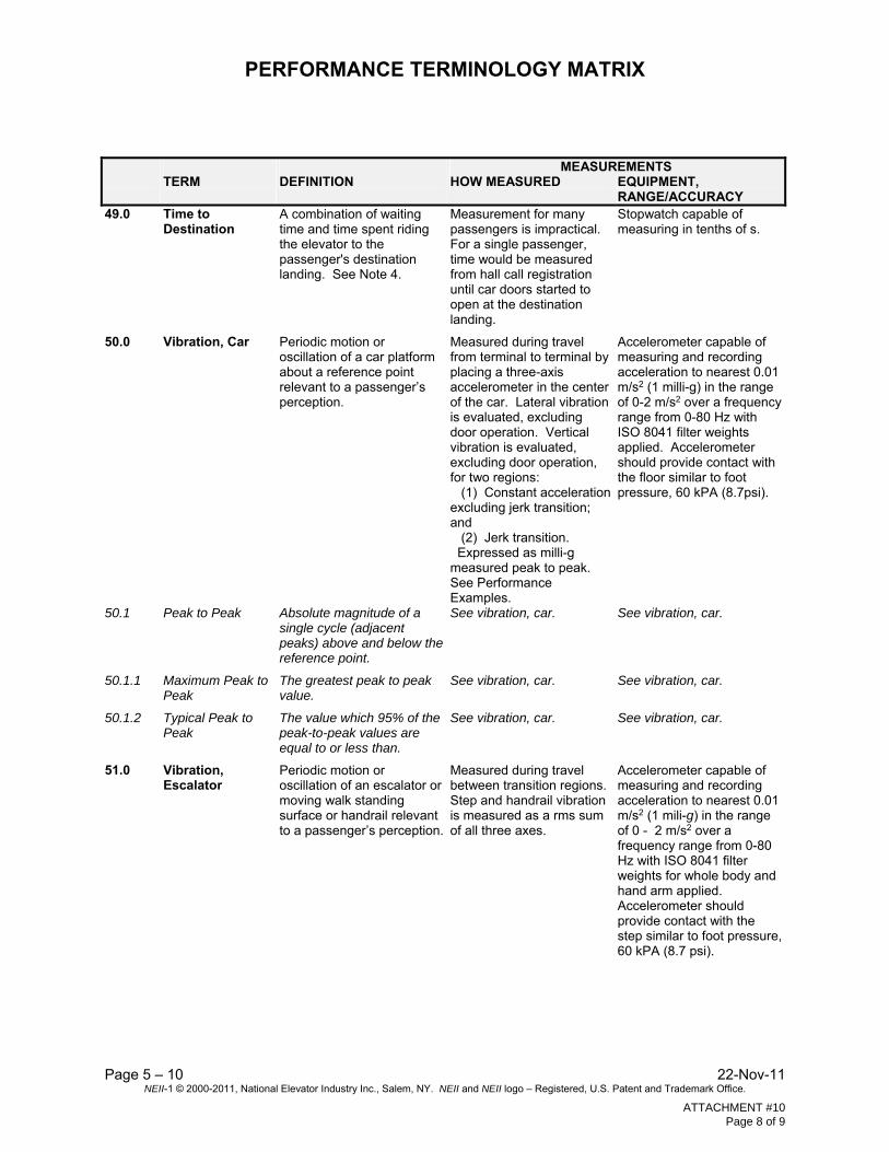
RANGE/ACCURACY 49.0 Time to
Destination A combination of waiting time and time spent riding the elevator to the passenger's destination landing. See Note 4.
Measurement for many passengers is impractical. For a single passenger, time would be measured from hall call registration until car doors started to open at the destination landing.
Stopwatch capable of measuring in tenths of s.
50.0 Vibration, Car Periodic motion or oscillation of a car platform about a reference point relevant to a passenger’s perception.
Measured during travel from terminal to terminal by placing a three-axis accelerometer in the center of the car. Lateral vibration is evaluated, excluding door operation. Vertical vibration is evaluated, excluding door operation, for two regions: (1) Constant acceleration excluding jerk transition; and (2) Jerk transition. Expressed as milli-g measured peak to peak. See Performance Examples.
Accelerometer capable of measuring and recording acceleration to nearest 0.01 m/s2 (1 milli-g) in the range of 0-2 m/s2 over a frequency range from 0-80 Hz with ISO 8041 filter weights applied. Accelerometer should provide contact with the floor similar to foot pressure, 60 kPA (8.7psi).
50.1 Peak to Peak Absolute magnitude of a single cycle (adjacent peaks) above and below the reference point.
See vibration, car. See vibration, car.
50.1.1 Maximum Peak to Peak
The greatest peak to peak value.
See vibration, car. See vibration, car.
50.1.2 Typical Peak to Peak
The value which 95% of the peak-to-peak values are equal to or less than.
See vibration, car. See vibration, car.
51.0 Vibration, Escalator
Periodic motion or oscillation of an escalator or moving walk standing surface or handrail relevant to a passenger’s perception.
Measured during travel between transition regions. Step and handrail vibration is measured as a rms sum of all three axes.
Accelerometer capable of measuring and recording acceleration to nearest 0.01 m/s2 (1 mili-g) in the range of 0 - 2 m/s2 over a frequency range from 0-80 Hz with ISO 8041 filter weights for whole body and hand arm applied. Accelerometer should provide contact with the step similar to foot pressure, 60 kPA (8.7 psi).
ATTACHMENT #10 Page 8 of 9
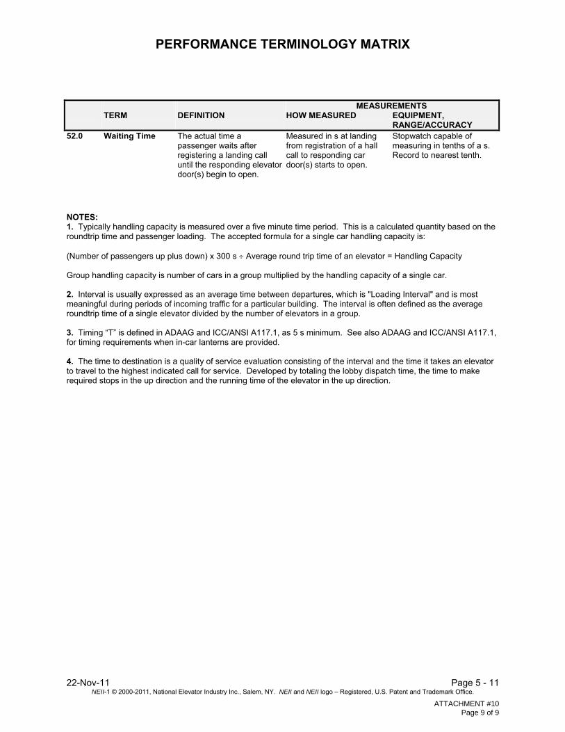
PERFORMANCE TERMINOLOGY MATRIX
22-Nov-11 Page 5 - 11 NEII-1 © 2000-2011, National Elevator Industry Inc., Salem, NY. NEII and NEII logo – Registered, U.S. Patent and Trademark Office.
MEASUREMENTS TERM DEFINITION HOW MEASURED EQUIPMENT,
RANGE/ACCURACY 52.0 Waiting Time The actual time a
passenger waits after registering a landing call until the responding elevator door(s) begin to open.
Measured in s at landing from registration of a hall call to responding car door(s) starts to open.
Stopwatch capable of measuring in tenths of a s. Record to nearest tenth.
NOTES: 1. Typically handling capacity is measured over a five minute time period. This is a calculated quantity based on the roundtrip time and passenger loading. The accepted formula for a single car handling capacity is: (Number of passengers up plus down) x 300 s Average round trip time of an elevator = Handling Capacity Group handling capacity is number of cars in a group multiplied by the handling capacity of a single car. 2. Interval is usually expressed as an average time between departures, which is "Loading Interval" and is most meaningful during periods of incoming traffic for a particular building. The interval is often defined as the average roundtrip time of a single elevator divided by the number of elevators in a group. 3. Timing “T” is defined in ADAAG and ICC/ANSI A117.1, as 5 s minimum. See also ADAAG and ICC/ANSI A117.1, for timing requirements when in-car lanterns are provided. 4. The time to destination is a quality of service evaluation consisting of the interval and the time it takes an elevator to travel to the highest indicated call for service. Developed by totaling the lobby dispatch time, the time to make required stops in the up direction and the running time of the elevator in the up direction.
ATTACHMENT #10 Page 9 of 9

PERFORMANCE STANDARDS MATRIX NEW ESCALATOR and MOVING WALK INSTALLATION
22-Nov-11 Page 5 – 19 NEII-1 © 2000-2011, National Elevator Industry Inc., Salem, NY. NEII and NEII logo – Registered, U.S. Patent and Trademark Office.
ESCALATOR MOVING WALKUnit of Measurement Metric Imperial Metric Imperial Metric Imperial Speed
m/s
ft/m
0.5
100
0.46 – 0.61
90 -120
Width 5
mm
in.
600, 800 or 1000
24, 32 or
40
1000
40
Escalator Rise – Moving Walk Length
m
ft
5
17
30
100
MOTION Contract Speed Regulation
%
%
5
5
5
5
Step Vibration rms (maximum) 7
milli-g
milli-g
15
15
15
15
Handrail Vibration rms (maximum) 8
milli-g
milli-g
50
50
50
50
Step/Skirt Performance Index 10
≤
≤
0.15
0.15
SOUND: (maximum) Sound - at Top or One End
dBA
dBA
66
66
64
64
Sound - at Bottom or One End
dBA
dBA
62
62
64
64
Sound - Middle of Run
dBA
dBA
60
60
61
61
Performance Standards based on the following: 1. Typical measurement taken with a maximum of two people on the unit. 2. Typical measurement for new escalator equipment at prestige office building. 3. Handrail to step/pallet speed should vary no more than 3%. 4. Typical measurements for horizontal pallet-type moving walks. 5. Denotes step/pallet width. 6. Measurements taken in normal direction of operation. Vibration measurements taken on inclined portion of
escalator. 7. Step measurements weighted according to ISO 8041 Whole Body Combined, expressed as rms units. 8. Handrail measurements weighted according to ISO 8041 Hand Arm, expressed as rms units. 9. Ambient noise 50 dBA maximum. 10. Step/skirt performance index may be ≤ 0.25 when a skirt deflector is provided.
ATTACHMENT #11 Page 1 of 1

VIBRATION DIRECTION DIAGRAM ELEVATOR
Page 5 – 16 22-Nov-11 NEII-1 © 2000-2011, National Elevator Industry Inc., Salem, NY. NEII and NEII logo – Registered, U.S. Patent and Trademark Office.
Y HORIZONTAL ACCELERATION SIDE TO SIDE (Post to Post)
Z VERTICAL ACCELERATION
X HORIZONTAL ACCELERATION FRONT TO BACK
Z
Y
X
Measurement Based Upon The Following Procedure: 1. The instrument shall be placed in the center of the car. 2. The instrument should be in firm contact with the finished car floor. 3. The instrument should be placed level on the car floor. 4. Measurement should begin prior to door close motion and should end subsequent to
door open motion at the end of the ride
ATTACHMENT #12 Page 1 of 2
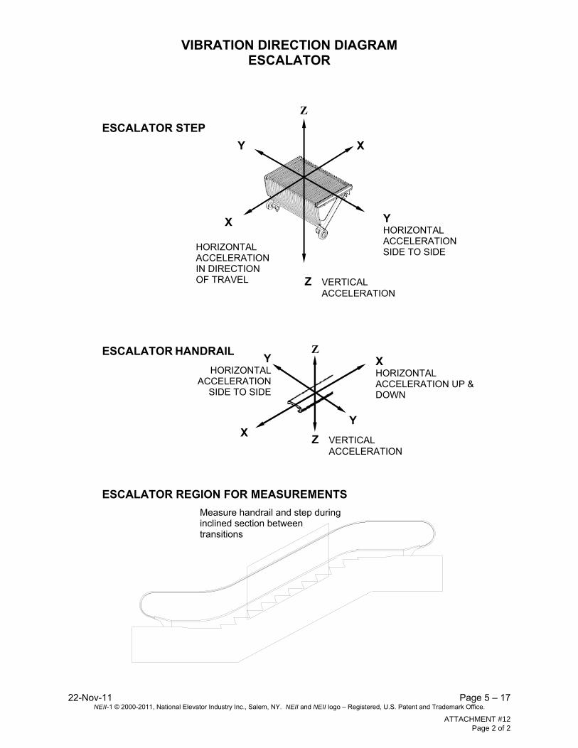
VIBRATION DIRECTION DIAGRAM ESCALATOR
22-Nov-11 Page 5 – 17 NEII-1 © 2000-2011, National Elevator Industry Inc., Salem, NY. NEII and NEII logo – Registered, U.S. Patent and Trademark Office.
ESCALATOR STEP
ESCALATOR HANDRAIL
ESCALATOR REGION FOR MEASUREMENTS
X HORIZONTAL ACCELERATION IN DIRECTION OF TRAVEL
X
Y HORIZONTAL ACCELERATION SIDE TO SIDE
Z
Y
Z VERTICAL ACCELERATION
X HORIZONTAL ACCELERATION UP & DOWN
Y HORIZONTAL
ACCELERATION SIDE TO SIDE
Y X
Measure handrail and step during inclined section between transitions
Z
Z VERTICAL ACCELERATION
ATTACHMENT #12 Page 2 of 2

5. NEII® COMMITTEE SCOPES AND LONG-RANGE OBJECTIVES
GENERAL
The National Elevator Industry, Inc. (NEII®) Committees will collaborate and work cooperatively to advance their long-range objectives. For example, the Government Affairs and Central Code Committees work jointly on the adoption of the PBC.
NEII® PERFORMANCE STANDARDS COMMITTEE Scope:
The Performance Standards Committee reports to the CCC and develops industry standards that can be used as guidelines for building transportation equipment to achieve appropriate performance and maintain code and safety compliance.
NEII® Performance Standards Committee Long-Range Objectives:
Expand NEII®-1 to add a white paper and templates on MCP’s; Add guidelines in NEII®-1 for compliance with the maintenance requirements in A17.1/ B44
(including PES certification), A17.7/ B44.7, etc.; Update NEII®-1 Energy Efficiency Guidelines; Promote the harmonization of NEII®/ISO positions on energy measurement and classification ; Expand NEII®-1 to address green building technology; Keep NEII®-1 current with industry technology; and Develop destination dispatch elevator accessibility guidelines for NEII®-1.
ATTACHMENT #13 Page 1 of 1