NEELACHAL ISPAT NIGAM LIMITED IRON AND STEEL PLANT …
241
NO.MEC/GS/Q693/11/Elect/03, Rev.0 JANUARY, 2006 NEELACHAL ISPAT NIGAM LIMITED DUBURI, ORISSA - 755026 IRON AND STEEL PLANT FOR INDIA POWER DISTRIBUTION GENERAL SPECIFICATION KALINGA NAGAR INDUSTRIAL COMPLEX SHOP ELECTRICS INSTRUMENTATION MECON LIMITED RANCHI - 834002 TELECOMMUNICATION (GS-03)
Transcript of NEELACHAL ISPAT NIGAM LIMITED IRON AND STEEL PLANT …
NO.MEC/GS/Q693/11/Elect/03, Rev.0 JANUARY, 2006
NEELACHAL ISPAT NIGAM LIMITED
DUBURI, ORISSA - 755026
IRON AND STEEL PLANT
FOR
INDIA
POWER DISTRIBUTION
GENERAL SPECIFICATION
KALINGA NAGAR INDUSTRIAL COMPLEX
SHOP ELECTRICS
INSTRUMENTATION
MECON LIMITEDRANCHI - 834002
TELECOMMUNICATION
(GS-03)
01 - 1
ELECTRICAL SYSTEM
01 GENERAL
01.01 Standards
The design, manufacture, assembly and testing as well as performance of the equipment
shall conform to the IPSS (Inter Plant Steel Standard) in respect of items for which
IPSS have been issued, otherwise, to the relevant IS specifications (latest revision). In
case the Tenderer is not in a position to comply fully with certain IPSS/IS
specifications, or in respect of certain items for which there are no IPSS/IS
specifications, the Tenderer may base his proposals on IEC recommendations or other
reputed national or international standards subject to the approval of the Purchaser.
All equipment supplied and all work done including system design and detailed
engineering shall also comply with the statutory requirements of the Government of
India, the state Government and with the Indian Electricity Rules.
In case of any contradiction between the data given in the Technical Specification and
this General specification, data given in the Technical specification shall prevail.
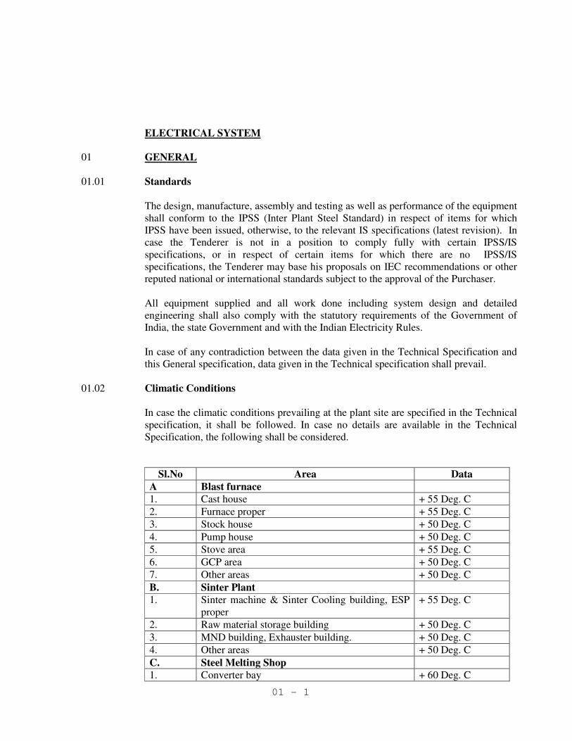
01.02 Climatic Conditions
In case the climatic conditions prevailing at the plant site are specified in the Technical
specification, it shall be followed. In case no details are available in the Technical
Specification, the following shall be considered.
Sl.No Area Data
A Blast furnace
1. Cast house + 55 Deg. C
2. Furnace proper + 55 Deg. C
3. Stock house + 50 Deg. C
4. Pump house + 50 Deg. C
5. Stove area + 55 Deg. C
6. GCP area + 50 Deg. C
7. Other areas + 50 Deg. C
B. Sinter Plant
1. Sinter machine & Sinter Cooling building, ESP
proper
+ 55 Deg. C
2. Raw material storage building + 50 Deg. C
3. MND building, Exhauster building. + 50 Deg. C
4. Other areas + 50 Deg. C
C. Steel Melting Shop
1. Converter bay + 60 Deg. C
01 - 2
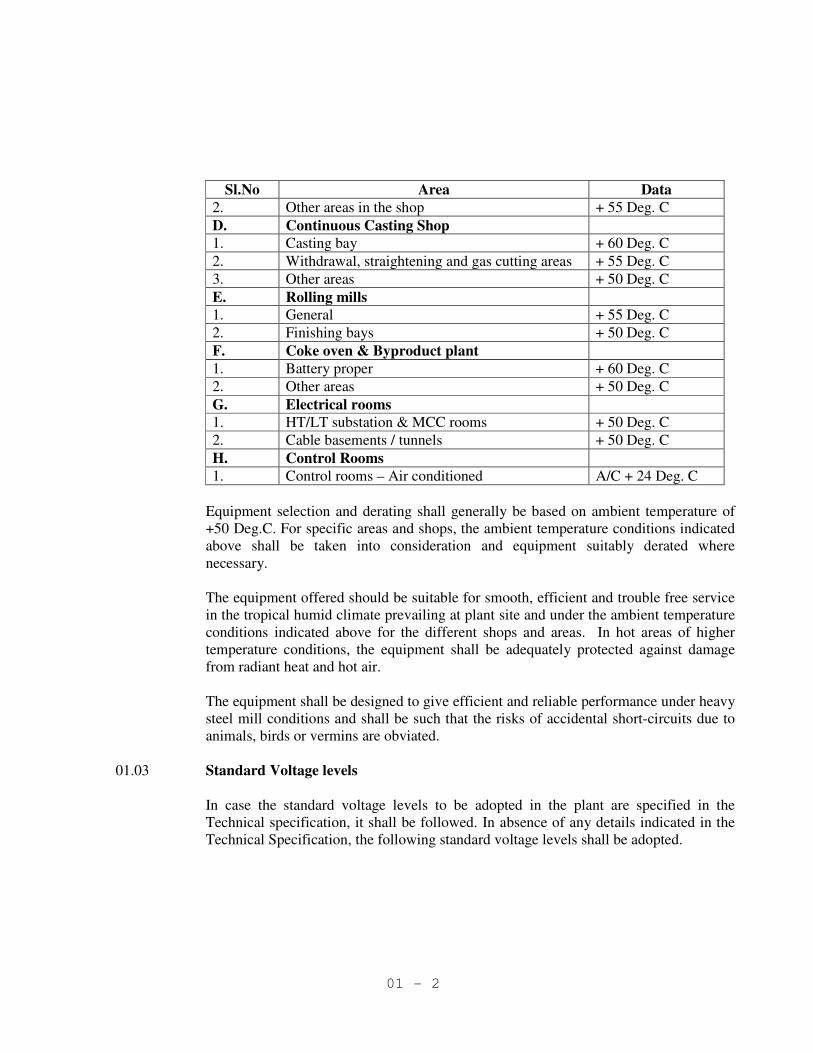
Sl.No Area Data
2. Other areas in the shop + 55 Deg. C
D. Continuous Casting Shop
1. Casting bay + 60 Deg. C
2. Withdrawal, straightening and gas cutting areas + 55 Deg. C
3. Other areas + 50 Deg. C
E. Rolling mills
1. General + 55 Deg. C
2. Finishing bays + 50 Deg. C
F. Coke oven & Byproduct plant
1. Battery proper + 60 Deg. C
2. Other areas + 50 Deg. C
G. Electrical rooms
1. HT/LT substation & MCC rooms + 50 Deg. C
2. Cable basements / tunnels + 50 Deg. C
H. Control Rooms
1. Control rooms – Air conditioned A/C + 24 Deg. C
Equipment selection and derating shall generally be based on ambient temperature of
+50 Deg.C. For specific areas and shops, the ambient temperature conditions indicated
above shall be taken into consideration and equipment suitably derated where
necessary.
The equipment offered should be suitable for smooth, efficient and trouble free service
in the tropical humid climate prevailing at plant site and under the ambient temperature
conditions indicated above for the different shops and areas. In hot areas of higher
temperature conditions, the equipment shall be adequately protected against damage
from radiant heat and hot air.
The equipment shall be designed to give efficient and reliable performance under heavy
steel mill conditions and shall be such that the risks of accidental short-circuits due to
animals, birds or vermins are obviated.
01.03 Standard Voltage levels
In case the standard voltage levels to be adopted in the plant are specified in the
Technical specification, it shall be followed. In absence of any details indicated in the
Technical Specification, the following standard voltage levels shall be adopted.

01 - 3
Sl.
No
Description Data
33 kV, 3 phase, 50 Hz, resistance earthed
11kV, 3 phase, 50 Hz, resistance earthed
1 HTAC
6.6 kV, 3 phase, 50 Hz, resistance earthed
2. LTAC 415V, 3 Phase, 50 Hz, 4 wire, solidly earthed
3. DC supplies voltage 220 Volts,
4. DC voltage for load having
individual converters
900V, 750V, 660V, 460V, 230V
5. AC control and signaling
voltage
240V, +10% obtained using suitable control
transformer.
6. DC control and signaling
voltage
220V
7. Control voltage for HT
switchgear equipment
220V DC from battery
8. Special socket outlets for
portable lamps
24V, single phase, 50 Hz, AC obtained through
suitable transformers
9. Electro-magnetic brakes 220V, DC, obtained through individual rectifiers
10. Solenoid valves Generally 24V,DC, unearthed
11. Machine tools lighting 110V, single phase, 50 Hz, lighting AC obtained
through centre tapped transformers.
12. Sockets for Welding
purposes
415V, 100A, 3 pin plus earth with plug
interlocked switch
13. Sockets for hand tools 240V, 15A, 2 pin plus earth with plug interlocked
switch
14. Illumination system 240V AC, 50HZ.
15. PLC power supply 415/240V AC, 50 Hz, obtained through UPS
16. Monitoring and signaling
in electronic installations,
mimic panels
24/48V, DC
01.04 Symmetrical short circuit ratings:
The three phase symmetrical short-circuit ratings of the switchgear at the different
voltage levels shall be as follows unless specifically indicated in the Technical
specification:
Sl.
No.
Description Data
1. 33 kV switchgear 26.2 kA for 3 sec.
2. 11 & 6.6 kV switchgear 40 kA for 3 sec.
3. 415 V switchgear 50 kA for 1 sec.
01 - 4
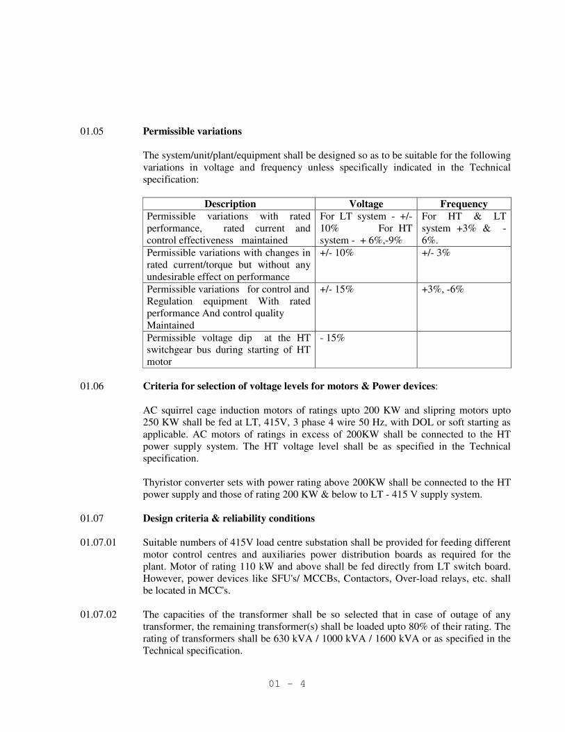
01.05 Permissible variations
The system/unit/plant/equipment shall be designed so as to be suitable for the following
variations in voltage and frequency unless specifically indicated in the Technical
specification:
Description Voltage Frequency
Permissible variations with rated
performance, rated current and
control effectiveness maintained
For LT system - +/-
10% For HT
system - + 6%,-9%
For HT & LT
system +3% & -
6%.
Permissible variations with changes in
rated current/torque but without any
undesirable effect on performance
+/- 10% +/- 3%
Permissible variations for control and
Regulation equipment With rated
performance And control quality
Maintained
+/- 15% +3%, -6%
Permissible voltage dip at the HT
switchgear bus during starting of HT
motor
- 15%
01.06 Criteria for selection of voltage levels for motors & Power devices:
AC squirrel cage induction motors of ratings upto 200 KW and slipring motors upto
250 KW shall be fed at LT, 415V, 3 phase 4 wire 50 Hz, with DOL or soft starting as
applicable. AC motors of ratings in excess of 200KW shall be connected to the HT
power supply system. The HT voltage level shall be as specified in the Technical
specification.
Thyristor converter sets with power rating above 200KW shall be connected to the HT
power supply and those of rating 200 KW & below to LT - 415 V supply system.
01.07 Design criteria & reliability conditions
01.07.01 Suitable numbers of 415V load centre substation shall be provided for feeding different
motor control centres and auxiliaries power distribution boards as required for the
plant. Motor of rating 110 kW and above shall be fed directly from LT switch board.
However, power devices like SFU's/ MCCBs, Contactors, Over-load relays, etc. shall
be located in MCC's.
01.07.02 The capacities of the transformer shall be so selected that in case of outage of any
transformer, the remaining transformer(s) shall be loaded upto 80% of their rating. The
rating of transformers shall be 630 kVA / 1000 kVA / 1600 kVA or as specified in the
Technical specification.

01 - 5
01.07.03 The rating of circuit breakers and CTs shall be sufficient for the actual loads taking into
consideration derating factors due to ambient temperature as well as for the mounting
of the component in the switchboard.
01.07.04 6.6 kV panel mounted load break switches with earthing switches of adequate rating
shall be provided in the transformer primaries.
01.08 Motor starting and permissible voltage dips
01.08.01 Solid state soft start with energy saving device shall be adopted preferably wherever
energy saving is of major consideration for all H.T. & L.T. A.C. motors. Voltage dip on
starting of the largest L.T. motor shall be limited to 15% of the nominal voltage at the
motor terminals.
01.09 Spare units
01.09.01 Every H.T and L.T. switchboards / MCC / PDBs etc. shall be provided with 20% spare
cubicles/modules. These spare cubicles/modules shall be complete with the circuit
breakers/contactor/starters/other accessories and shall be fully wired. Minimum number
of spare feeders on any board shall be 2 nos. The rating and type of spare feeder shall
be decided during detailed engineering stage.

02 - 1
02. POWER DISTRIBUTION EQUIPMENT
02.01 33/6.6 kV SWITCHBOARD
02.01.01 Code and Standards
The switchboards and the mounted equipment shall conform to the latest revisions of the
following Indian standards:
IS:12729 General requirements for switchgear and controlgear for voltages
exceeding 1000 V.
IS:13118 General requirement for circuit breakers for voltages above 1000 V.
IS:3427 Metal-enclosed switchgear and control gear for voltages above
1000 V but not exceeding 11000 V.
IS:5082 Material for data for aluminium bus bars.
IS:9920 Switches and switch isolators for voltages above 1000V.
IS:9921 AC disconnectors (islators) and earthing switches for voltage above
1000 V.
IS:9046 AC contractors of voltage above 1000 V upto and including 1100
V.
IS:12661 HV motor starters.
IS:13703 Low voltage fuses.
IS:2705 Current transformers.
IS:3156 Voltage transformers.
IS:1248 Electrical indicating instruments.
IS:722 Integrating meters.
IS:3231 Electrical relays for power system protection.
IS:6875 Control switches and push buttons.
IS:694 PVC-insulated cables for working voltages voltage upto and
including 1100 V.
IS:2544 Porcelain post-insulators for systems with nominal voltage greater
than 1000 V.
IS:11353 Guide for uniform system of marking and identification of
conductors & apparatus terminals.
IS:5578 Guide for marking of insulated conductors.
IS:3618 Phosphate treatment of iron and steel for protection against
corrosion.
IS:6005 Code of practice of phosphating of iron and steel.
IS:5 Colours for ready mixed paints and enamels.

02 - 2
Wherever Indian Standards are not available, relevant IEC standards shall be applicable.
02.01.02 General Requirement
• The switchgear shall be of metal clad, single bus bar/Double bus bar as applicable, self
standing, dust proof construction, indoor cubicle type fitted with SF6/vacuum circuit
breakers in fully draw out execution.
• The circuit breakers shall be suitable for following duties
⇒ To withstand inrush magnetizing currents of transformers & capacitor bank ‘ON’ and
‘OFF’ operation.
⇒ To withstand switching off over voltages caused due to break of lightly loaded low
capacity cage type induction motors. It shall also withstand DOL starting of motor with
large starting time, and repeated starting like one hot start and two successive cold starts.
⇒ Transient surge produced by one CB due to severe chopping during rapid interruptions
of inductive current e.g motors, shall be within limits allowable for overhauled motors
according to IEC34 part 1 otherwise suitable surge absorber shall be provided.
• The controls, indicating lamps, relays and meters shall be mounted on breaker cubicle itself.
(for 6.6kV Switchboard).For 33 kV panel separate control & relay panel shall be provided .
• Operation counter, close/open mechanical indications spring charged/ discharged indication
shall be provided.
• All circuit breakers shall have motor operated spring charged mechanism for closing and
shunt tripping coil ( 220V DC). Closing coil shall be suitable to operate between 85% to
110% of rated voltage and tripping coil between 70-110% of rated voltage. Spring charging
motor shall operate between 85-110% of rated AC. Voltage.
• Jumpers in the cubicle also shall be of same current rating as that of the breaker. Only the
jumpers connected to CT shall be rated according to CT rating.
• A manually operated device to enable charging of closing springs.
• Manual / Mechanical tripping arrangement for emergency tripping of CBs.
• All circuit breaker truck shall have service, test and draw out positions. Test position shall
engage only the auxiliary (control) contacts to close the CB during testing.
• Panel door switch shall be provided for illumination inside panel.
• Anti pumping feature shall be provided.
• All live parts shall be insulated by tapping, supported by suitably designed insulators. Proper
insulation of bus bars upper and lower contacts of breakers, vacuum bottles (for VCB) and
sealing of opening of bushings shall be provided to eliminate accidental contacts.
Switchboard busbars shall be taped by proper grade of insulating tape.
• The cubicle shall be provided with a position changing gear arrangement in such a way that
by engaging detachable device from outside the front door, it shall be possible to move the
breaker truck and change position without opening the cubicle door. Facilities for pad
locking in each position shall be provided.
• Each cubicle shall have mimic diagram with metal strip.
• Each cubicle shall be of compartmentalized construction and shall have separate
compartments for bus bars, CTs and outgoing cables, metering & protection devices.
• All circuit breaker trucks of same rating shall be identical in all respects (except metering
and protective devices) and shall be interchangeable with similar breaker panel.
• Continuous earth bus shall be provided throughout the board.
• The position of various control switches, push buttons, levers etc requiring manual operation
shall be at a height not less than 450mm and shall not exceed 1850mm from the finished

02 - 3
floor level.
In the design of the switchgear the following positive interlocking shall be provided.
1. It shall not be possible to move the truck/ cassette from the isolated to the Service Position
unless low voltage plug and socket connections have been made.
2. It shall not be possible to disconnect the low voltage plug and socket as long as the circuit
breaker truck/cassette is in service position.
3. It shall not be possible to withdraw the truck/cassette without disconnecting the low voltage
plug and socket.
4. It shall not be possible to move the truck/ cassette from the service to the isolated position or
vice-versa with the circuit breaker in the `ON' position.
5. It shall not be possible to switch on the circuit breaker when the truck is in between the
isolated and the service positions (except in test position).
6. It shall be possible to switch on the earthing switch only when the truck is in the isolated
position, wherever an integral earth switch is provided.
7. It shall not be possible to open the circuit breaker enclosure when the breaker is ON or to
have access to any part of the draw out assembly which is live when the circuit breaker is in
the service position.
8. Shutters shall be lockable in closed position.
9. Where local/remote selector switches are called for , it shall be ensured that:
* The breaker can be closed locally only if the breaker truck is in the test position and the
local/remote selector switch is in local position.
* The breaker can be operated from remote panel (in shop) only when the breaker truck is
in service position and the local/remote selector switch is in remote position.
* The breaker can be tripped locally regardless of the position of the breaker truck.
02.01.03 Operating Mechanism
The operating mechanism parts shall be designed to give longer life, trouble free operation and
require minimum maintenance.
The material and components used shall have chopping current limited to minimum.
02.01.04 Insulation Levels
Insulation levels corresponding to the rated voltage shall be as follows:
Nominal voltage (kV) : 6.6 33
Highest system voltage (kV) : 7.2 36
One minute power frequency withstand voltage (kV) : 20 70
1.2/50 micro sec impulse withstand voltage (kV) : 60 170
Clearence in air : As per IEC
02.01.05 Short Circuit Strength
• Rated short time withstand current shall not be less than the system short circuit level
specified for the stipulated duration.
• Rated peak withstand current shall not be less than 2.5 times the system short circuit level.

02 - 4
02.01.06 Auxiliary Buses for Control & Protection
1. Control supply buses for AC and DC
2. Signalling supply
3. PT secondary voltage
4. Spare buses – 2 nos.
02.01.07 Provision of Surge Suppressor
In case of breakers like VCB that give rise to over voltage surges due to current chopping
phenomenon, surge suppressors to be provided at the load side terminals of the breakers to limit
the switching surges to value limited for as per IEC.
02.01.08 Annunciation Schemes
• Flag indications for all faults for which individual protective relays have been specified.
• Warning signalling (as applicable) on individual panels:
a) All transformer warning / signalling conditions (group signal from corresponding
transformer control panel / substation
b) Loss of trip circuit supply
c) Earthfault
d) Control supply failure
e) PT fuse failure / MCB tripping
f) SF6 gas pressure low in case SF6 breaker is used.
• Emergency signalling for tripping of HT breakers on fault
• One common signal for warning and one signal for emergency from each panel to be wired
to a common annunciation panel of the switchboard, where specified.
• Annunciators for warning and emergency signaling condition on individual panels of solid
state facia window type. Common audio signaling with Accept, Reset, and Test push buttons
for the switchboard where common annunciation panel is not specified. Audio signaling to
have distinct tones for warning and emergency.
02.01.09 Bus Bar and Connections
• Power buses of EC grade aluminium alloy equivalent to E91E WP as per IS-5082 –1981
or high conductivity electrolytic grade copper as per IS : 613-1984. The bus bars shall
be tinned at joints.
• Control and Auxiliary buses of electrolytic grade copper.
• The continuous rating of the main horizontal bus shall not be less than the rating of the
incomer specified, where not specified, the rating to be selected for at least 125% of the
maximum demand of the switchboard taking into account spare feeders.
• The vertical bus rating
For incomer : Not less than that of horizontal bus
For outgoing : Not less than that of the outgoing breaker,
irrespective of relay setting.
• Final operating temperature under continuous operation in enclosure limited to 90oC. by
thermometer method.
• Both horizontal and vertical bus bars to be designed and supported to withstand the
thermal and dynamic stress corresponding to rated short time and peak withstand current
specified.

02 - 5
• Cross-section of main horizontal bus to be uniform throughout the switchboard and
continuous in one transport unit.
• Bus bar arrangement as per IS 375.
• Phase identification by color in each panel.
• Bus bars (horizontal as well as vertical) shall be provided with heat shrinkable, non
tracking, low absorption type sleeving conforming to international standards for full
voltage for 33 kV and 6.6 kV switchboard.
• Bus bar joints and tap off connections of bolted type with zinc dichromate high tensile
steel bolts, nuts and spring washers, fishplates with accessories at the end of a transport
unit for site connections.
• Bus bar support insulators of non-hygroscopic material having high impact and
dielectric strength with an anti tracking contour.
02.01.10 Internal Control Wiring
• Control wiring shall be carried out by 1100V grade PVC insulated, single core multi
stranded copper wire of minimum cross section 1.5 sq. mm. For CT circuits however,
2.5 sq. mm cross section shall be used.
• Flexible wire of 2.5 sq.mm shall be used from CT chamber to relay chamber and shall
have protection against heat & mechanical damage due to flash over. Use of heatproof
sleeves and rigid conduit shall be made to run the control wires from back to front.
• Wiring and terminal arrangement for all panels shall be carried out as per approved
scheme.
• Flexible wires protected against mechanical damage for wiring to door mounted devices.
• Wires identified at each end in accordance with schematic diagrams by interlocked type
ferrules. These shall be firmly located so that these do not move.
• Color code for control wiring
AC – Black Earth wire – Green
DC – Light grey Trip circuit – Red
• All connections external to a feeder, all the auxiliary contacts of the HV breaker and at
least 1 NO & 1 NC spare contacts of the relays shall be brought to terminal blocks.
• Interconnection between panels of adjacent shipping sections to be brought out to a
separate terminal block.
• No bunch shall contain more than 12 wires.
• Wiring shall not be joined or tied between the terminal points.
• Control wires shall be run in earthed metallic flexible conduits when laid in HV bus
chamber.
• Not more than two connections shall be provided on any one terminal.
• Heat proof arrangement for the passage of wiring in HT panel.
• All telemetering signals shall be wired to terminal strips.
02.01.11 External Terminations
02.01.11.01 Control Terminations
• 650V grade multi-way open type terminal blocks of non-tracking moulded plastic
complete with insulated barriers, stud type terminals, washers, nuts and lock nuts and
identification strips.
• All terminals going out of the switch board shall be brought to a separate terminal board
marked "External Termination". These will be easily accessible.

02 - 6
• External terminal block shall be provided in the relay chamber with proper clamping
facilities for cable dressing.
• Control terminals shall be suitable to receive two numbers 2.5 sq. mm copper conductor.
• 20% spare terminals in each control terminal block. Terminal blocks in separate groups
shall be provided for DCS/PLC, remote control panels, transformer marshalling boxes,
local push button stations, etc.
• Gland plate for control cables shall be of adequate size to accommodate and to facilitate
glanding of all the control cables coming from external equipment.
• Terminal blocks shall be placed separately for internal looping and external looping.
02.01.11.02 Power Terminations
• Suitable for accepting cable/bus trunking as specified.
• Sufficient space and support arrangement inside each panel to accommodate HT cable
termination kits and sealing kits suitable for the size and number of XLPE cables.
• Dummy panels to be provided adjacent to the switch panel, where the required number
cable terminations cannot be accommodated in the cabling chamber of the main panel.
Rear extension not acceptable.
• Where more than one cable have to be terminated per unit, the arrangement shall permit
connection and disconnection of cables separately without disturbing other cables.
• Where specified the following cable termination accessories, suitable for the type, size
and number of cables to be terminated, to be supplied with switchboard.
⇒ Cable sockets with all HT terminals (sockets set at such an angle that cable tails
can be brought up for termination with minimum bending and setting)
⇒ HT cable termination and sealing kits
⇒ Power cable termination facilities shall be designed to facilitate easy approach to
CTs.
⇒ Double compression type brass cable glands and crimping type tinned heavy
duty copper lugs for HT, LT power and control cables.
02.01.12 Protection and Measurement
02.01.12.01 Electrical Protection
• Selection of protective scheme will be based mainly on reliability, sensitivity, selectivity. All
main protections shall be fast acting type in order to clear the faulty system from the healthy
system in earliest possible time to minimise damage to equipment and ensure continuity of
power supply.
02.01.12.02 Protective scheme requirement
• All the main protective relays shall be microprocessor based numerical & communicable
type.
• Auxiliary relays, timers switches etc. required to make the scheme complete shall be
considered as part of the scope of work.
• All CT-PT shall be suitable for the relay-meter requirement - lead burden
• All CT-PT wires shall be brought to test terminal blocks before connecting to circuits.
• The circuits of various protections (coming from other panels) shall be connected to master
trip relays through aux. relays (flag indicated).
• VAA type aux. relays shall be provided for each transformer fault. Connection of the relay
shall be through links to facilitate maintenance.
02 - 7
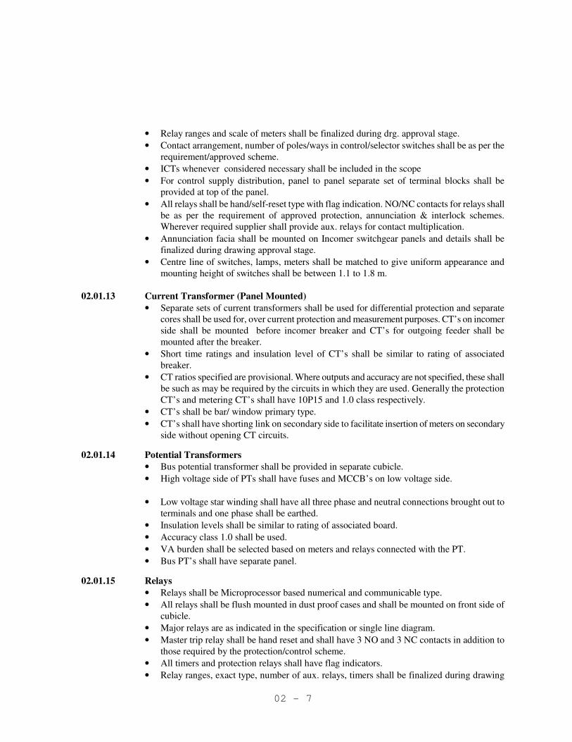
• Relay ranges and scale of meters shall be finalized during drg. approval stage.
• Contact arrangement, number of poles/ways in control/selector switches shall be as per the
requirement/approved scheme.
• ICTs whenever considered necessary shall be included in the scope
• For control supply distribution, panel to panel separate set of terminal blocks shall be
provided at top of the panel.
• All relays shall be hand/self-reset type with flag indication. NO/NC contacts for relays shall
be as per the requirement of approved protection, annunciation & interlock schemes.
Wherever required supplier shall provide aux. relays for contact multiplication.
• Annunciation facia shall be mounted on Incomer switchgear panels and details shall be
finalized during drawing approval stage.
• Centre line of switches, lamps, meters shall be matched to give uniform appearance and
mounting height of switches shall be between 1.1 to 1.8 m.
02.01.13 Current Transformer (Panel Mounted)
• Separate sets of current transformers shall be used for differential protection and separate
cores shall be used for, over current protection and measurement purposes. CT’s on incomer
side shall be mounted before incomer breaker and CT’s for outgoing feeder shall be
mounted after the breaker.
• Short time ratings and insulation level of CT’s shall be similar to rating of associated
breaker.
• CT ratios specified are provisional. Where outputs and accuracy are not specified, these shall
be such as may be required by the circuits in which they are used. Generally the protection
CT’s and metering CT’s shall have 10P15 and 1.0 class respectively.
• CT’s shall be bar/ window primary type.
• CT’s shall have shorting link on secondary side to facilitate insertion of meters on secondary
side without opening CT circuits.
02.01.14 Potential Transformers
• Bus potential transformer shall be provided in separate cubicle.
• High voltage side of PTs shall have fuses and MCCB’s on low voltage side.
• Low voltage star winding shall have all three phase and neutral connections brought out to
terminals and one phase shall be earthed.
• Insulation levels shall be similar to rating of associated board.
• Accuracy class 1.0 shall be used.
• VA burden shall be selected based on meters and relays connected with the PT.
• Bus PT’s shall have separate panel.
02.01.15 Relays
• Relays shall be Microprocessor based numerical and communicable type.
• All relays shall be flush mounted in dust proof cases and shall be mounted on front side of
cubicle.
• Major relays are as indicated in the specification or single line diagram.
• Master trip relay shall be hand reset and shall have 3 NO and 3 NC contacts in addition to
those required by the protection/control scheme.
• All timers and protection relays shall have flag indicators.
• Relay ranges, exact type, number of aux. relays, timers shall be finalized during drawing

02 - 8
approval stage.
• All instantaneous current protection relays shall be of 3 pole type.
• In HT switchboard two nos. bus PT’s , with U/V relays, neutral displacement relays, timer
etc. to be provided.
02.01.16 Indicating Instruments
• All indicating instruments shall conform to IS:1248-1983 and IS - 2419-1979.
• Shall be capable of withstanding system fault current taking into account CT saturation.
• Shall be back connected.
• Shall be located in the upper part of the panel.
• Shall have 144 sq. mm square flush case, non-reflecting type, clearly divided and indelibly
marked scales, sharply out lined pointers and zero adjusting device.
• The minimum scale reading shall not be more than 10%. Maximum reading shall be 15%
full load for transformers panels.
• Each voltmeter shall be calibrated with coil hot. The scale shall be open between 60% to
125% of normal volts and shall be suppressed below 60% of normal volts.
• Class of accuracy shall be 1.5 or better.
• The full load reading of each ammeter shall occur at the most prominent part of the scale.
The minimum scale reading shall not be more than 10%. Maximum reading shall be 15%
full load for transformer panels and 600% full load for motor panels.
02.01.17 Annunciators
• Shall be of static type.
• Hooter and bell for trip and alarm indication respectively.
• Shall be suitable to work on DC supply as specified.
• Test, accept and reset facilities (with push button) shall be provided on each panel.
• Suitable audio - visual indication shall be provided on DC failure. Audio alarm with reset
facility shall be provided. Visual indication shall be panel- wise.
• Spare annunciation points shall be wired upto terminal blocks. 20% spare facias shall be
provided.
• Each point shall have two bunch LEDs in parallel.
• All trip points facia shall have red color and non trip points white color.
• The cover plate of facia shall be flush with panel
• Shall be capable to receive simultaneous signals
• Shall be capable to receive signal during testing mode
• Tenderer shall ensure the non-presence of spurious signals due to influence of external
electromagnetic / electrostatic interference on the annunciation wiring and switching
disturbances from neighboring circuits within panels
• Scope of supply includes all interconnections, bell hooter, buzzer, alarm facility, push button
etc. required to achieve complete function of above scheme.
• Sequence shall be as follows:
VISUAL AUDIO
ON OCCURRENCE OF FAULT LAMP FLASHING ON
ON ACCEPTANCE LAMP STEADY “ON” OFF
ON RESET OFF OFF
ON TEST LAMP FLASHING ON
• Annunciation in the switchboard shall have following provisions;

02 - 9
⇒ Each transformer shall have 6 facia.
⇒ Each bus PT shall have 6 facia.
• Bus coupler or tie shall have sufficient facia (for each feeder to indicate tripping + 20 %
spare).
• All auxiliary relays of transformer feeders shall have 4 NO contacts and all master trip relays
shall have two NO contact for remote/ DCS/PLC indication for repeat annunciation in
addition to contacts required for scheme under scope of works.
• Warning and emergency points shall be as per the list approved during detail engineering
stage. In general all tripping points and alarm points shall be annunciated. (Transformer
alarm and tripping point shall be provided with auxiliary relays to have duplicate
annunciation at remote panel/DCS/PLC, etc).
• One common point shall be provided to indicate operation of annunciation system of the
complete board (in case of any trouble in the board in tie feeder, bus coupler, incomer, etc).
02.01.18 Control Supply
• Control supply buses shall run throughout the switchgear.
• Two DC feeders shall be taken in each board controlled by MCCB’s.
• In each panel for controlling of its DC supply MCCB (DC duty) shall be used. DC auto
changeover and manual changeover facility shall be provided. Failure of each DC supply
shall be monitored in the switchboard as well as at remote.
• 240V AC supply shall be taken from a station aux. board.
• Each section shall have separate feed with automatic changeover scheme.
• Each panel shall have one MCB for controlling its AC supply.
• Sub circuits shall be protected with HRC fuses in each panel for indication lamps, closing
and tripping circuits.
02.01.19 Earthing Devices
• Either integral earthing switch or a separate earthing switch shall be provided to facilitate
earthing of busbars and any feeder circuit.
• Earthing truck (if included) shall have PT and alarm provision. (Separate trucks shall be
provided for feeder and bus earthing through bus PT panel in each switchboard). 1 no.
earthing truck for feeder earthing and 1 no. for busbar earthing shall be provided for each
board. It shall not be possible to use bus earthing truck for feeder earthing and vice-versa.
• Rating of earthing device shall be in line with associated board.
• Interlock provision shall be there so that incomer can not be closed if bus earthing device is
connected.
• In case feeders are having integral earth switch, earthing trucks may not be required.
02.01.20 Indicating Lamps
• Type - Cluster type LED lamps.
Color shall be as follows;
ON : RED
OFF : GREEN
AUTOTRIP : AMBER
TRIP CKT. HEALTHY : WHITE
SPRING CHARGED : BLUE
Indication lamps shall be provided for CB Service, test & drawout position.
02 - 10
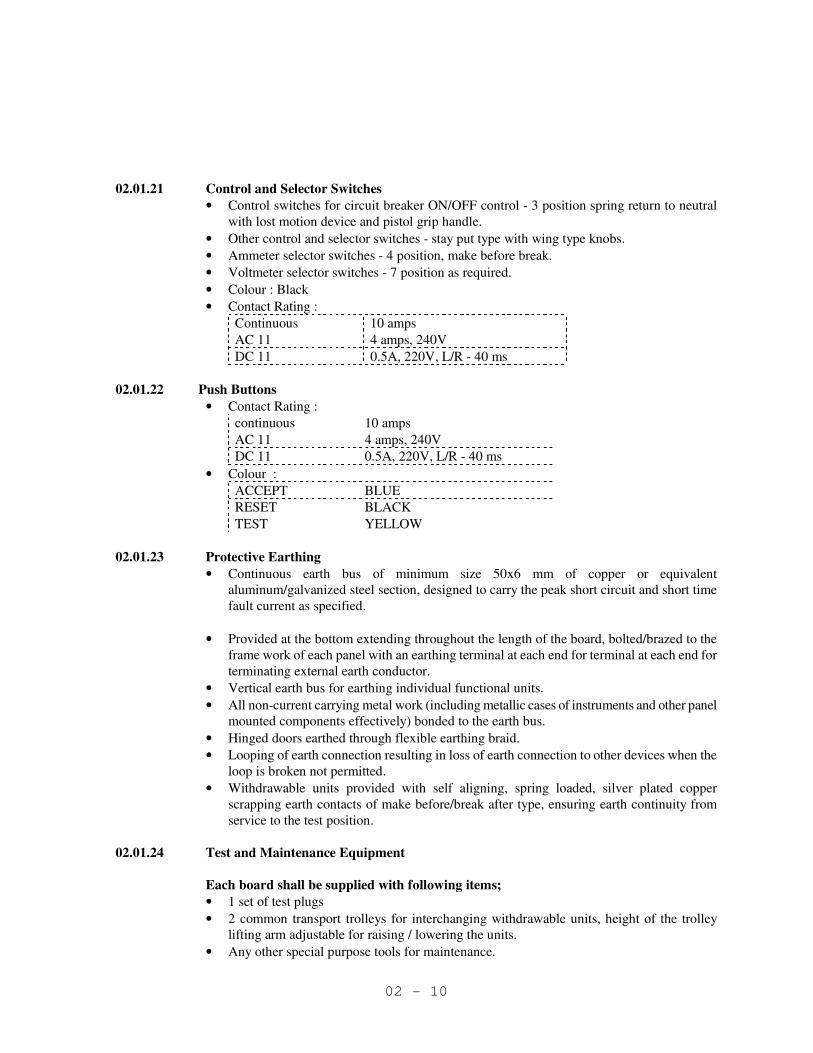
02.01.21 Control and Selector Switches
• Control switches for circuit breaker ON/OFF control - 3 position spring return to neutral
with lost motion device and pistol grip handle.
• Other control and selector switches - stay put type with wing type knobs.
• Ammeter selector switches - 4 position, make before break.
• Voltmeter selector switches - 7 position as required.
• Colour : Black
• Contact Rating :
Continuous 10 amps
AC 11 4 amps, 240V
DC 11 0.5A, 220V, L/R - 40 ms
02.01.22 Push Buttons
• Contact Rating :
continuous 10 amps
AC 11 4 amps, 240V
DC 11 0.5A, 220V, L/R - 40 ms
• Colour :
ACCEPT BLUE
RESET BLACK
TEST YELLOW
02.01.23 Protective Earthing
• Continuous earth bus of minimum size 50x6 mm of copper or equivalent
aluminum/galvanized steel section, designed to carry the peak short circuit and short time
fault current as specified.
• Provided at the bottom extending throughout the length of the board, bolted/brazed to the
frame work of each panel with an earthing terminal at each end for terminal at each end for
terminating external earth conductor.
• Vertical earth bus for earthing individual functional units.
• All non-current carrying metal work (including metallic cases of instruments and other panel
mounted components effectively) bonded to the earth bus.
• Hinged doors earthed through flexible earthing braid.
• Looping of earth connection resulting in loss of earth connection to other devices when the
loop is broken not permitted.
• Withdrawable units provided with self aligning, spring loaded, silver plated copper
scrapping earth contacts of make before/break after type, ensuring earth continuity from
service to the test position.
02.01.24 Test and Maintenance Equipment
Each board shall be supplied with following items;
• 1 set of test plugs
• 2 common transport trolleys for interchanging withdrawable units, height of the trolley
lifting arm adjustable for raising / lowering the units.
• Any other special purpose tools for maintenance.

02 - 11
02.01.25 Constructional Features
02.01.25.01 Mechanical Design
• Sheet steel clad, compartmentalized, floor mounted, free standing design.
• Minimum sheet steel thickness: doors & covers - 2 mm cold rolled, other load bearing
members - 2.5 mm
• Doors shall be provided with lock and key arrangement
• Degree of protection shall be IP4X.
• Assembled on base channel of structural steel ISMC 75 painted black.
• Operating height shall be between 450 to 1800 mm. Switchboard height not to exceed 2500
mm.
• Earthed metallic barriers between compartments and between vertical sections.
• Seal off bushings wherever bus bars pass through metallic partition.
• Zinc bichromated and passivated hardwares.
• Transport unit not larger than 3.2 mts.
• Removable lifting arrangement for each transport unit.
• Lockable front doors with concealed hinges with the door not forming part of the draw-out
truck.
• Panels shall be extensible on both sides.
• Removable sheet steel covers shall be provided at rear.
• Explosion vent for each chamber
• Control cables entry shall be from front side.
• CTs shall be located in such a way that that they are easily accessible.
• Panel door switch shall be provided for illumination inside the panel.
• All live parts shall be insulated by taping, supported by suitably designed insulators. Proper
insulation of bus bars, upper and lower contacts of breakers and sealing of opening of
bushings shall be provided to eliminate accidental contacts.
• Screw wire mesh in the power cable chamber of incoming feeder is to be provided.
02.01.25.02 Labels
• Switchboard designation nameplate at the center of the board with letters not less than 25
mm high.
• Panel designation number on each panel, both in front and rear
• Inscription plate for each feeder on the door
• Door front mounted devices to have labels directly below them
• Labels made on non-rusting metal or 3 ply lamicoid with engraved inscription of white
letters (minimum 3 mm high) on black background.
• Label designation and size of lettering subject to approval.
• Bus side and cable side shutters labeled for identification.
02.01.25.03 Surface Treatment
All metal parts of the panel to undergo surface treatment that includes de-rusting, cleaning,
chemically degreasing, pickling in acid, cold rinsing, phosphating and passivating followed by
spraying with two coats of zinc oxide primer and baking in oven.
Shade of paint Panel interior : Off white shade
Exterior : Light grey 631, as per IS-5

02 - 12
02.01.26 Technical particulars and design parameters
Sl.
No.
Particulars 33 kV 6.6 KV
1. Type SF6/VCB SF6/VCB
2. Service Indoor Indoor
3. Enclosure IP-4X IP-4X
4. Nominal System Voltage 33 kV 6.6 kV
5. Highest System Voltage 36 kV 7.2 kV
6. No. of phases and frequency 3ph. 50 Hz 3ph. 50 Hz
7. Busbar material Electrolytic grade
aluminium alloy
equivalent to
E91EWP as per
IS:5082:1981
Electrolytic grade
aluminium alloy
equivalent to E91EWP
as per IS:5082:1981
8. Bus Color code RYB RYB
9. System Earthing Earthed through
earthing
transformer
Resistance Earthed
10. Circuit Breaker Rating
10.1 Continuous Current Rating at
45 deg C
- -
10.2 Short Circuit Rating 26.2 kA 40 kA
10.3 Short Circuit duration 3 sec 3 sec
11. Rated making Current 100 kA 100 kA
12. Busbar Rating As specified As specified
13. Power Frequency Withstand
voltage
70 kV for 1 minute 20 kV
for 1 minute
14. Impulse withstand voltage
(1.2/50 micro sec)
170 kV 60kV
15. Control Voltage 220 V DC 220 V DC
16 Spring charge motor voltage 240 V AC 240 V AC
17. CT Ratio -
Secondary Current
1A
-
Secondary Current 1A
18. PT ratio - STAR/ STAR/ Open
delta (33/√3) / (.11/√3) /
(.11/3)
(6.6/√3) / (.11/√3) /
(.11/3)
19. Aux. Contacts 6 NO + 6 NC 6 NO + 6 NC
20. Termination
20.1 Incomers BUSDUCT/XLPE
Cables
BUS DUCT/ XLPE
Cables
20.2 Outgoings XLPE Cables XLPE Cables

02 - 13
Sl.
No.
Particulars 33 kV 6.6 KV
21 Clearance in air
Phase to phase (mm)
Phase to earth (mm)
As per IEC
As per IEC
02.01.27 Details of major protections for 6.6 kV panels
Sl.
No.
Type of feeder Protection
1 Bus Coupler
feeder.
� Over-Current IDMT O/C (51-3 Pole)
� Earth Fault (51 N-Single Pole)
2 Incomer from
transformer
� Over-Current IDMT O/C (51-3 Pole)
� Earth Fault (51 N-Single Pole)
� Composite Transformer Differential and Restricted
earth fault Protection (87 + 64R)
� Standby earth fault protection (51G)
� Under voltage protection (27) with timer (2)
� Fuse failure protection of line PT (97) (for alarm)
3 Incomer from
switchboard
� Over-Current IDMT O/C (51-3 Pole)
� Earth Fault (51 N-Single Pole)
� Under voltage protection (27) with timer (2)
� Fuse failure protection of line PT (97) (for alarm)
4 Outgoing
Power Supply
Feeder to
switchboards
� Over-Current IDMT O/C (51-3 Pole)
� Earth-Fault (51 N-Single Pole)
5 Outgoing
Transformer
feeder (all types of
transformers)
� Over Current (INST(50) & IDMT O/C 51-3 Pole)
� Earth-Fault IDMT 51 N
� Provision to trip on transformer fault including stand
by earth fault protection (signal to be received from
downstream breaker panel)
6 Outgoing
Motor Feeder
� Motor Protection (99)
� Provision to trip on under voltage (signal received
from bus PT)
� Provision to trip on signal from temperature element in
motor
02 - 14
Sl.
No.
Type of feeder Protection
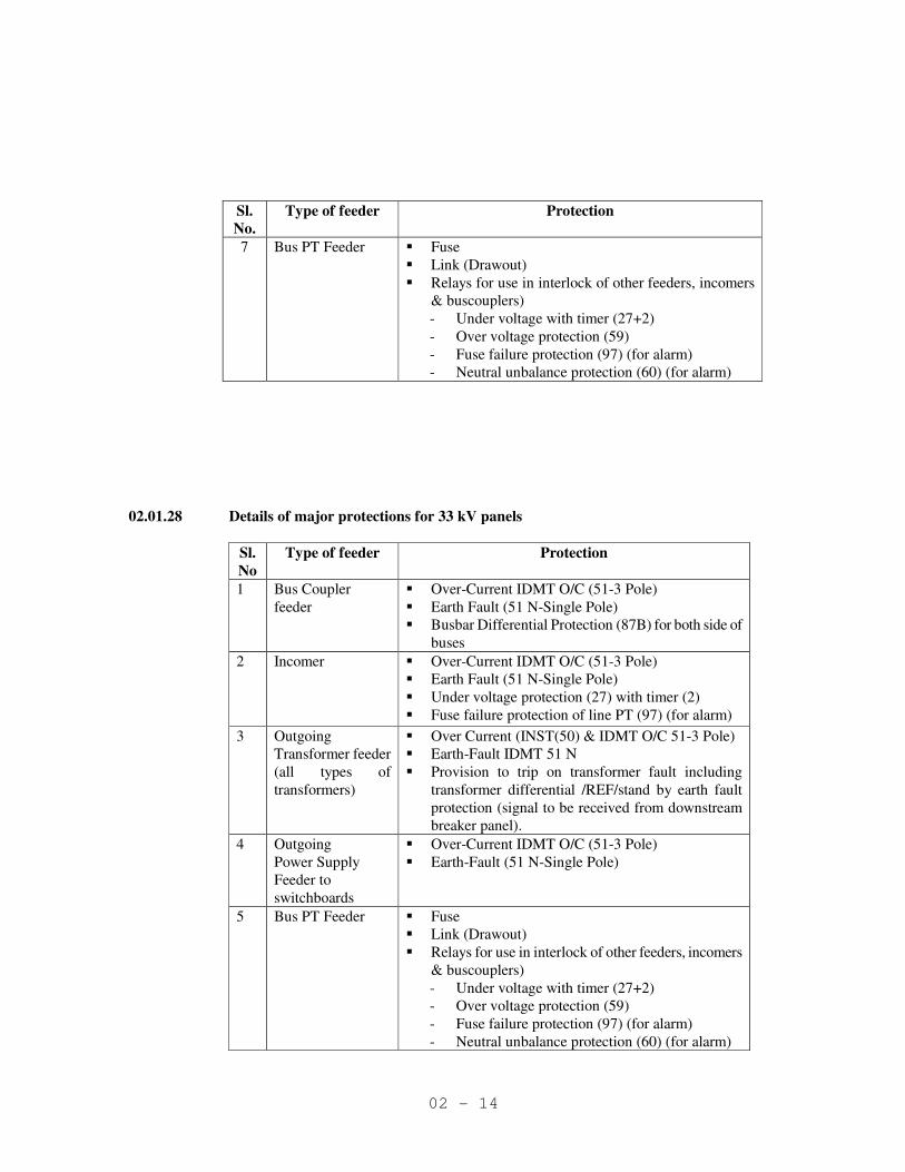
7 Bus PT Feeder � Fuse
� Link (Drawout)
� Relays for use in interlock of other feeders, incomers
& buscouplers)
- Under voltage with timer (27+2)
- Over voltage protection (59)
- Fuse failure protection (97) (for alarm)
- Neutral unbalance protection (60) (for alarm)
02.01.28 Details of major protections for 33 kV panels
Sl.
No
Type of feeder Protection
1 Bus Coupler
feeder
� Over-Current IDMT O/C (51-3 Pole)
� Earth Fault (51 N-Single Pole)
� Busbar Differential Protection (87B) for both side of
buses
2 Incomer
� Over-Current IDMT O/C (51-3 Pole)
� Earth Fault (51 N-Single Pole)
� Under voltage protection (27) with timer (2)
� Fuse failure protection of line PT (97) (for alarm)
3 Outgoing
Transformer feeder
(all types of
transformers)
� Over Current (INST(50) & IDMT O/C 51-3 Pole)
� Earth-Fault IDMT 51 N
� Provision to trip on transformer fault including
transformer differential /REF/stand by earth fault
protection (signal to be received from downstream
breaker panel).
4 Outgoing
Power Supply
Feeder to
switchboards
� Over-Current IDMT O/C (51-3 Pole)
� Earth-Fault (51 N-Single Pole)
5 Bus PT Feeder � Fuse
� Link (Drawout)
� Relays for use in interlock of other feeders, incomers
& buscouplers)
- Under voltage with timer (27+2)
- Over voltage protection (59)
- Fuse failure protection (97) (for alarm)
- Neutral unbalance protection (60) (for alarm)
02 - 15
Sl.
No
Type of feeder Protection
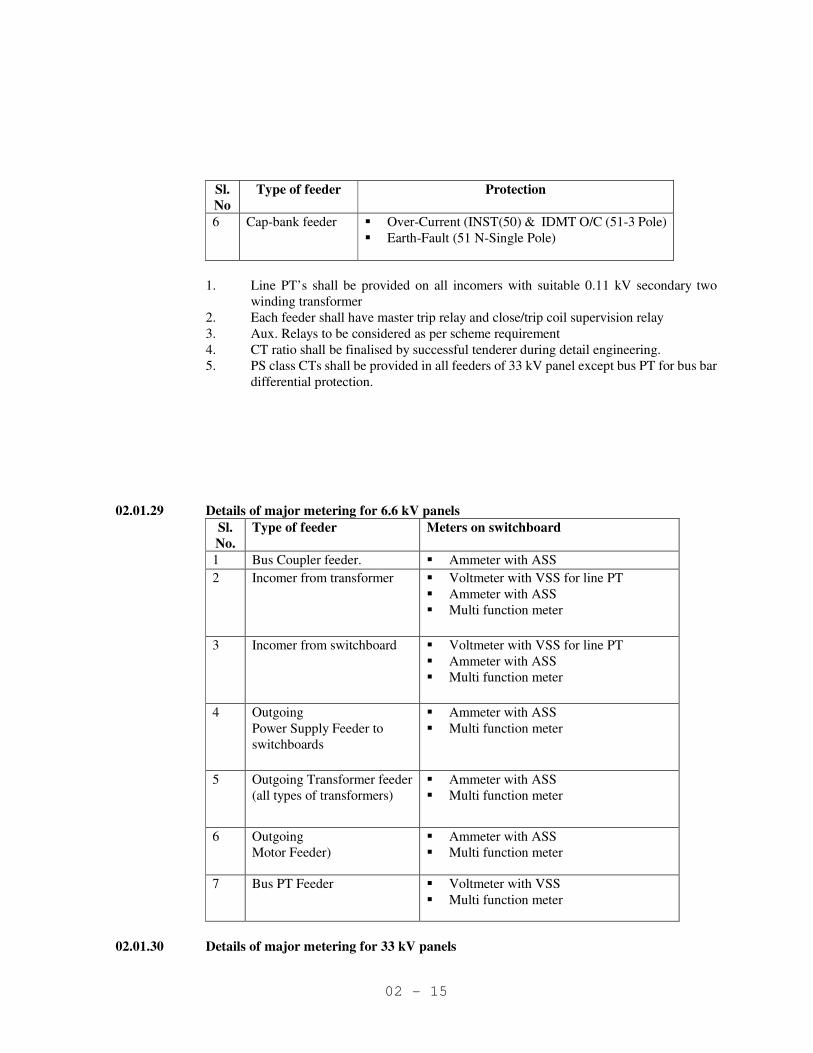
6 Cap-bank feeder � Over-Current (INST(50) & IDMT O/C (51-3 Pole)
� Earth-Fault (51 N-Single Pole)
1. Line PT’s shall be provided on all incomers with suitable 0.11 kV secondary two
winding transformer
2. Each feeder shall have master trip relay and close/trip coil supervision relay
3. Aux. Relays to be considered as per scheme requirement
4. CT ratio shall be finalised by successful tenderer during detail engineering.
5. PS class CTs shall be provided in all feeders of 33 kV panel except bus PT for bus bar
differential protection.
02.01.29 Details of major metering for 6.6 kV panels
Sl.
No.
Type of feeder Meters on switchboard
1 Bus Coupler feeder. � Ammeter with ASS
2 Incomer from transformer
� Voltmeter with VSS for line PT
� Ammeter with ASS
� Multi function meter
3 Incomer from switchboard
� Voltmeter with VSS for line PT
� Ammeter with ASS
� Multi function meter
4 Outgoing
Power Supply Feeder to
switchboards
� Ammeter with ASS
� Multi function meter
5 Outgoing Transformer feeder
(all types of transformers)
� Ammeter with ASS
� Multi function meter
6 Outgoing
Motor Feeder)
� Ammeter with ASS
� Multi function meter
7 Bus PT Feeder � Voltmeter with VSS
� Multi function meter
02.01.30 Details of major metering for 33 kV panels

02 - 16
Sl.
No.
Type of feeder Meters on switch board Meters on control panel
1 Bus Coupler
feeder
� Ammeter with ASS � Ammeter with ASS
2 Incomer � Voltmeter with VSS
(for both line PT )
� Ammeter with ASS
� Voltmeter with VSS
for line PT
� Multi function meter
3 Outgoing
Transformer
feeder
� Ammeter with ASS
� Ammeter with ASS
� KW meter
4 Outgoing
Power Supply
Feeder to
switchboards
� Ammeter with ASS
� KWh meter
� Ammeter with ASS
� Multi function meter
5 Bus PT Feeder � Voltmeter with VSS � Voltmeter with VSS
� Multi function meter
6
Capacitor Bank
Feeder
� Ammeter with ASS � Ammeter with ASS
� Multi function meter
02.01.31 Control and Relay Panel
Control & relay panel for 33kV switchyard equipment shall house relay, control and metering.
02.01.31.01 Constructional Features
- Panels shall be arranged to form a continuous board with the mimic and control
equipment.
- Panels shall be vertical, free standing, simplex type with rear hinged door, side terminal
blocks, control signaling circuit breakers, resistors, fuses, links, isolating switches etc.
- Flush mounted meters, relays, switches, signal lamps etc on front of the panel.
- Made of cold rolled pressed sheet steel thickness 2.5 mm.
- Provided with 75mm base channel and 15 mm anti vibration pad.
- Will have bottom cable entry
- Provided with space heater and interior illumination lamp with switches.
- Anodised aluminum / Chrome plated inscription plate both at back and front side of size
to enable a person to read from 5 meters shall be provided.
- All doors, removable covers and panels shall be casketed all around with neoprene
gaskets. Ventilating louvers, if provided shall have screens and filters. The screens shall
be made of either brass or GI wire mesh.
- The center line of switches, push buttons and indicating lamps shall be not less than
750mm from the bottom of the panel. The center line of relays, meters and recorders
shall be no less than 450mm from the bottom of the panel.
- All sheet steel work shall be with 7 tank process.
- After application of the primer, two coats of powder coating shall be provided. The
paint shade shall be 631 as per IS:5.
- Facia drawing shall be submitted by successful tenderer, to customer, for approval
- Components i.e. Pushbuttons, selector switches, indicating lamps, annunciation system,
meters etc. shall be as per requirement as finalised during detail engineering.

02 - 17
02.02 TRANSFORMER
02.02.01 Electrical Design
- Generally as per IS 2026 - 1977.
- 3 phase core type
- Rated output voltage ratio, vector group shall be as specified in Technical particulars for
design.
- Rated frequency 50 Hz, + 3%, -6%.
- Insulation level shall be designed according to the voltages specified below:
Nominal system voltage 6.6 kV 33 kV
Max. system voltage 7.2 kV 36 kV
One minute power frequency withstand
voltage
20 kV 70 kV
Peak impulse test withstand voltage 60 kV 170 kV
- Transformers shall be capable of delivering rated current at an applied voltage up to 105%
rated voltage without exceeding the temperature limits.
- Overload capacity as per IS 6600 - 1972 unless otherwise specified.
- Shall be operable at its rated capacity at any voltage within + 10% of rated voltage of the
particular tap.
- Permissible maximum temperature at rated output and principal tap ambient temperature of
45 deg. C
a) Top oil (by thermometer) : 85 deg C
b) Windings (by resistance method) : 95 deg. C
c) Maximum hot spot temp : 105 deg C
- Transformers shall be designed to withstand the thermal and dynamic stresses due to short
circuits at its terminals. Unless otherwise specified the duration of short circuit shall be 5
seconds.
- The maximum temperature at the end of the specified duration shall not be more than 250
deg. C with the temperature prior to short circuit corresponding to maximum permissible
overload.
- Designed for suppression of harmonics especially 3rd and 5th.
- In case of forced cooled transformers, these shall be able to deliver rated power for 10
minutes even if the forced cooling fails with the winding hot spot temperature limited to 140
deg C. Where the coolers are provided, similar operation shall be permissible for 20 minutes
on failure of one cooler.
02.02.02 Magnetic Circuit
� Low loss CRGO silicon steel shall be used.
- CRGO sheets shall be coated with insulation varnish compatible with the sealing
liquid.
- Ducts to be provided to ensure adequate cooling.
- Core, framework and clamps arranged and tightened to securely hold laminations in
order to prevent any settling of displacement in case of heavy shocks during
transport, handling or short circuits.
� Flux density under specified over voltage or frequency conditions shall be within the
maximum permissible for the laminations.
� Transformers shall be designed to withstand 110% over fluxing corresponding to rated
voltage.
02 - 18
02.02.03 Windings
� Material shall be electrolytic grade work hardened copper of high proof stress with more
numbers of radial supports.
� Shall be pre-compressed, press board, pre-stabilization of coil.
� Completed core and winding to be vacuum dried in full vacuum and impregnated
immediately.
� Shall be braced to withstand shocks due to rough handling, and forces due to short circuit,
switching or other transients.
� Permanent current carrying conductors within winding shall be brazed. Connections to
bushings and OLTC will be crimped.
� Coils shall be supported using blocks, spacers and cylinders.
� Insulating materials shall be compatible with transformer liquid under all service conditions.
� Leads to the terminal board and bushings shall be rigidly supported.
02.02.04 Insulation
Inter turn and inter coil insulation shall be designed such that dielectric stress is uniformly
distributed throughout the windings under all operating conditions.
02.02.05 On Load Tap Changer
02.02.05.01 Electrical Design
- Generally as per IS 8468-1977
- Automatic motor operated , resistive transition impedance type
- Suitable for bidirectional power flow unless specified otherwise.
- Tap Changer shall change the effective transformation ratio without providing phase
displacement.
- The tap changer shall have the same rating as the associated transformer with respect to
rated current, rated voltage, number of phases, insulation level, over loading capability and
short circuit withstand capacity.
- Number of steps 13 and rated step voltage 1.25% unless specified otherwise.
- Shall be suitable for connection to line end of neutral and of the winding as specified.
- DC Control supply voltage shall be 220V DC
02.02.05.02 General Arrangement
- Divertor switch contacts shall be housed in a separate oil chamber not communicating
with the oil in the main tank of the transformer.
- The oil used shall be transformer oil conforming to IS 355-1983.
- The OLTC oil chamber shall have oil filling and drain plug, relief vent and glass window
for seeing the level. A buchholz relay (hand reset type) also shall be fitted, the outlet of
which shall be connected to a separate conservator.
- A mechanical tap position indicator shall be provided locally.
- A mechanical operation counter shall be provided to indicate the number of operations
completed.
- The main contacts, switching contacts and transition contacts shall be of sliver faced
copper with maximum temperature rise of contacts at 150 % of rated current of
transformer limited to 20°C.
02 - 19
02.02.05.03 Control Features
- The OLTC shall have the following control regimes,
a) Local Manual operation
b) Local Electrical Operation
c) Remote electrical operation
d) Fully automatic operation
- In manual regime, the OLTC shall be operable by a person standing at the ground level
.The electrical operation shall be inhibited automatically once the manual operation is
restored to.
- For Electrical operation a suitable 3 phase, 415V AC Motor and associated starter with
thermal O/L relays, fuses, etc shall be provided.
- The manual electrical operation, either local or remote shall cause one tap movement only.
The control switch is to be returned to the OFF position between successive operations.
- Once a switching sequence has started, it shall always be completed. The tap changer shall
not stop in an intermediate position even in the event of control power failure.
- Mechanical stop shall be provided to prevent overrunning beyond the extreme tap
position. Electrical interlock through limit switches shall also be provided to cut off power
for electrical operation.
- A reverse tap change signal during an operation shall be ignored till the mechanism comes
to rest and reset the circuit for a fresh operation.
- Emergency stopping provision shall be provided both at the local and remote control
panels.
- An indication ' tap change in progress ' shall be available at the remote control panel.
- Power and control circuit of motor shall be interlocked.
- If control is set to 'automatic', it shall not be possible to operate the OLTC by manual
electric or hand operating gear.
- Automatic voltage regulator with voltage transformer shall be provided for automatic
control of OLTC. The regulator shall have a delay between the sensing of change of
voltage and the change of tap. The delay shall be inversely proportional to the degree of
voltage variation. The voltage setting shall be continuously adjustable from 90% to 100%
of rated voltage. The dead band shall be continuously adjustable from 0.5% to 4% of rated
voltage. The operation of OLTC shall be blocked if the voltage drops to less than 80% of
rated voltage. A hand reset operation indicator and self reset alarm contact shall be
provided which operates:
a) Instantaneously if auxiliary supply fails.
b) With a delay of 3 seconds if regulated supply fails or drops below 80% of setting
c) If regulated voltage remains +3% outside the set dead band for more than 15
minutes.
- Where specified, line drop compensation shall be provided with resistive and reactive
drops upto 20% of rated voltage in steps of 1%. Resistance and reactance settings shall be
independently adjustable.
- CTs required for current reference shall form part of transformer, mounted on bushings.
The secondary terminals of the CTs shall be wired to outdoor type terminal block provided
with shorting links.
02.02.05.01 Local OLTC Control Cabinet
- Dust vermin and weather proof outdoor cubicle with lockable door, enclosure class IP-55.
- Shall house the drive motor for OLTC, starter, local control equipment, indicators for tap

02 - 20
position, counters, etc.
02.02.05.05 List of Accessories for OLTC
- Operation counter
- Local tap position indicator
- Buchholz relay
- Oil surge Relay
- Conservator
- Dehydrating breather
- Drain plug and oil filling plug
- Local OLTC control cubicle.
02.02.06 Off-Circuit Tap Switch (Where Applicable)
- Externally hand operated with easily accessible links.
- Designed for sustained over current of at least 150% of the rated current of the winding.
- Shall not occupy any intermediate position between clearly marked tap position.
- Capable of repeated operation and withstanding short circuit forces.
- Tap position indicator
- Inspection and/or repair shall not require removal of transformer core from tank.
- Integral handle with padlocking arrangement
02.02.07 Tank
- Welded thick gauge plates stiffened and reinforced to withstand without deformation all
stresses applied during transport and operation or short circuit conditions.
- Oil tight welds and joints
- Fully assembled transformer with its radiators, conservator and other fittings shall
withstand for one hour a pressure corresponding to twice the normal head of liquid or to
the normal pressure plug 35 kW/sq. m, whichever is higher, measured of the base of the
tank.
- Plates shall be protected internally against corrosion due to insulating liquid.
- Provided with inspection opening and cover/with handling equipment) to provide access
to bushing connections.
- Form of cover shall be such as to prevent any stagnant water deposit and to drain gas
bubbles towards the buchholz relay
- Tank (with radiators when welded to tank) shall be capable of withstanding of 250 mm of
mercury vacuum.
02.02.08 Conservator and Breather
- Conservator mounted on frame, integral with tank in such a manner that under all
conditions and the lowest oil level the bushings remain under the head of liquid.
- Conservator volume shall be sufficient to maintain oil seal from ambient to oil temperature
of 90 deg. C
- Oil filling hole with cap, and a drain valve to drain the oil completely shall be provided.
One end of the conservator shall be bolted into position so that it can be removed for
cleaning purposes.
- Silica gel breather with inspection window and oil seal shall be mounted at 1.4 m from
ground level and connected to conservator.
- Prismatic type oil level gauge with maximum and minimum levels marked. One 150 mm

02 - 21
diameter dial type magnetic level gauge with alarm and trip contacts shall also be
provided.
02.02.09 Buchholz Relay
- Double float relay as per IS 3677 - 1966.
- Shut off valves on either sides of the buchholz relay
- Pot cocks at the top and bottom of relay drain plug, inspection window, calibrated scale,
terminal box with oil tight double compression type brass gland.
- Potential free, self reset independent alarm and trip contacts, rated to make, break and
carry 2 amps at 110 V DC. No auxiliary relay shall be used to multiply the contacts.
Contacts are to be wired to the marshalling box.
02.02.10 Cooling
02.0210.01 General
The cooling system provided may be either of the following or a mixed system of these, as
specified.
ONAN - Oil natural, air natural
ONAF - Oil natural, air forced i.e with cooling fans
Where forced cooling is provided, the forced cooling shall be automatically started/stopped
through contacts of winding temperature indicator, the settings, of which shall be separately
adjustable at site.
02.02.10.02 Radiators
Radiators may be detachable type directly mounted or separately mounted flanged, gasketted and
bolted connections shall be used for connecting the radiators to the tank.
The following accessories shall be provided for each radiator/radiator bank
a) Top and bottom shut off valves and blanking plates.
b) Bottom drain plug and top filling plug, air release plug
c) Lifting lugs
d) Thermometer pockets with thermometers in the inlet and outlet pipes (for separately
mounted radiator banks).
e) Top and bottom filter valves for each separately mounted radiator bank.
02.02.10.03 Forced Air System
- The fans shall be mounted in a suitable enclosure to ensure protection against rain.
- Galvanised wire mesh guard shall be provided.
02.02.11 Valves and connections
- Valves of sluice type with hand wheels
- Made of gun metal
- Clear indication of open and closed position
- Provided with blanking plates or screwed plugs
- Padlocking facility to lock in closed/open position.
02.02.12 Terminations
It shall be possible to withdraw the transformer easily after disconnecting the connections
without disturbing the cable terminations.
02 - 22
For cable termination
- Air insulated cable box suitable for the type and number of cables specified.
- Air insulated disconnection chamber with inspection opening
- Compression type brass cable glands with tinned copper lugs
- Bolted type gland plates.
- Sealing kits with associated accessories like stress relieving cones, insulating tape,
trifurcating boot, HT insulating tape, etc.
For bus duct termination
- When bus duct termination is specified, flanged throat shall be provided to suit the bus
duct. Flange ends and inspection openings shall have weatherproof gaskets.
02.02.13 Bushings
- Conforming to IS 3347 Part 5 - 1979, Part 3 - 1988 and 2099 - 1986.
- Minimum rated current of line and bushings shall be 1.5 times rated current of the
corresponding windings
- Clamps and fittings made of steel or malleable iron shall be hot dip galvanized.
- Bushings rated 400 Amps and above shall have non-magnetic clamps and fittings only.
- Neutral bushings shall be provided as required for earthing of neutral point.
- The creepage distance for bushings, insulators etc. shall be adequate for heavily polluted
atmosphere, and shall not be less than 25.4 mm / kV corresponding to the highest system
voltage.
02.02.13.01 Bushing current Transformers (Where applicable)
- CTs for REF protection and back up earth fault shall be provided on the neutral end.
- For differential protection, CTs shall be provided on primary side
- Removable at site without opening transformer tank cover/active parts.
- Secondary leads shall be brought to a weatherproof terminal box and from there to the
marshalling box.
02.02.14 Oil temperature Indicator
150 mm dial type thermometer with manual reset maximum reading pointer. There shall also be
two potential free contacts for alarm and trip signals. The alarm and trip settings shall be
independently adjustable. The temperature-sensing element mounted in a pocket of oil shall be
connected to the indicator through capillary tubing. Contact rating at DC shall be minimum 0.5
amps.
02.02.15 Winding Temperature Indicator
a) Local winding temperature indicator (WTI) shall have a 150 mm diameter dial type
indicator with a manual reset maximum reading pointer. There shall be two potential free
contacts for alarm and trip signals. For transformers with forced cooling, another set of
contacts shall be provided to start/stop the forced cooling system automatically. The
settings for closing/opening of each contact shall be independently adjustable. Contact
rating at DC11, 110V DC shall be minimum 0.5 amps. The device shall be complete with
lamp, sensing element, image coil, calibration device, auxiliary CTs etc. as required.
b) Remote winding temperature indicator with resistance type temperature detector, shall be
provided additionally.
02.02.16 Marshalling box
02 - 23
- All outgoing connections from the transformer i.e buchholz relay, temperature indicators,
level indicators, CT secondary, fault contacts for annunciation, including forced cooling
system and OLTC etc shall be wired to a marshalling box.
- Degree of protection of enclosure shall be IP 52 for indoor and IP 52 for outdoor type
respectively.
02.02.17 Remote Control Panel
The following minimum remote control/signalling provisions are to be made as applicable.
a) Remote control devices for manual electrical control of OLTC
b) Automatic voltage regulator and other accessories for automatic control of OLTC
c) Voltmeter to read secondary voltage of power transformer
d) Remote tap position indicator for OLTC
e) Signal lamps for 'tap changing in progress' for OLTC. ON/OFF status for pumps and
fans etc.
f) Push buttons, for control of forced cooling system fans and pumps
g) Remote winding temperature indicator
Audio-visual annunciation for the following abnormal operating conditions shall be provided as
applicable.
a) Oil level in transformer low (from magnetic level gauge)
b) Buchholz relay operation for transformer
c) High oil temperature in transformer
d) High winding temperature
e) Oil pressure low
f) Cooling fans failed
g) OLTC failed to operate on auto
h) OLTC motor tripped
i) Buchholz relay of OLTC operated
j) Aux. AC supply failed.
A solid state facia window type annunciation system shall be provided for this purpose, with the
following features.
i) On incidence of fault - A hooter comes on and window lamp
starts flashing
ii) On pressing ACCEPT button - Hooter stops, lamp becomes steady
iii) On pressing RESET button - Lamp goes off if fault is removed.
Lamp continues to glow if fault persists
The required alarm/trip contacts shall be wired to the marshalling box for connection to the
annunciation system.
02.02.18 Earthing
- All metal parts of the transformer with the exception of individual core laminations, core
bolts, and clamping plates shall be maintained at fixed potential by earthing.
- Two tinned copper earthing terminals
- One end of bushing CTs shall be earthed.
02.02.19 List of fittings and Accessories
- Identification plate
02 - 24
- Rating and diagram plates.
- First fill of oil as per IS-355, 1983 with 10% excess in drums
- Cooling system complete with accessories as specified
- ON load tap changer with accessories / Off-circuit tap switch as specified
- Conservator with oil level gauge
- Dehydrating breather
- Buchholz relay with alarm and trip contacts
- Oil filter valves at top and bottom of tank
- Drain off valve at lowest location to allow complete draining
- Oil sampling device at top and bottom
- Explosion vent with double diaphragm
- Pockets with thermometers for oil temperature and winding temperature indicators
- Bar type level gauge with alarm contacts
- HV, LV and neutral bushings.
- Bushing CTs as specified
- Dial type winding temperature indicator with maximum reading pointer and alarm and trip
contacts
- Lifting lugs and jacking pads
- Earthing terminals
- Inspection covers
- By-directional rollers/flanged wheels as specified
- Marshalling box.
- Flat base and foundation bolts.
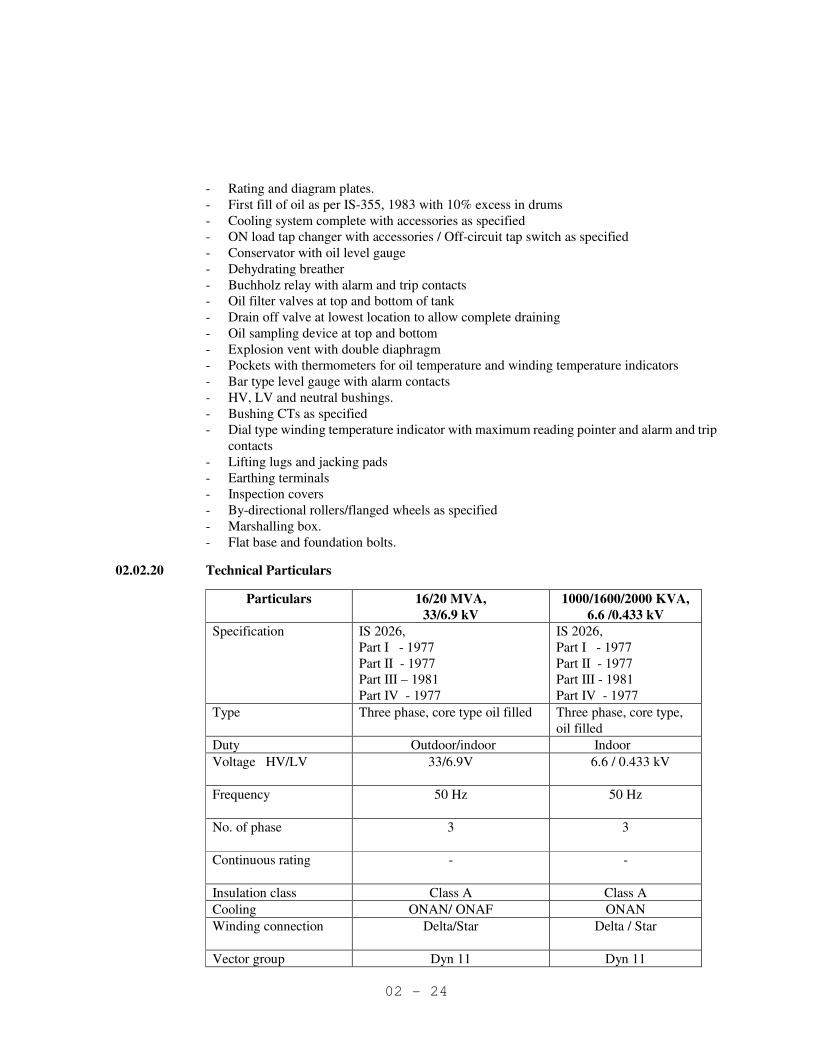
02.02.20 Technical Particulars
Particulars 16/20 MVA,
33/6.9 kV
1000/1600/2000 KVA,
6.6 /0.433 kV
Specification
IS 2026,
Part I - 1977
Part II - 1977
Part III – 1981
Part IV - 1977
IS 2026,
Part I - 1977
Part II - 1977
Part III - 1981
Part IV - 1977
Type Three phase, core type oil filled Three phase, core type,
oil filled
Duty Outdoor/indoor Indoor
Voltage HV/LV
33/6.9V 6.6 / 0.433 kV
Frequency
50 Hz 50 Hz
No. of phase
3 3
Continuous rating
- -
Insulation class Class A Class A
Cooling ONAN/ ONAF ONAN
Winding connection
Delta/Star Delta / Star
Vector group Dyn 11 Dyn 11

02 - 25
Particulars 16/20 MVA,
33/6.9 kV
1000/1600/2000 KVA,
6.6 /0.433 kV
Neutral grounding
Resistance earhted Solidly earthed
System earthing
33kV – earthed through earthing
transformer
6.6kV – resistance earthed
6.6 kV – Resistance
earthed
415 V - Solidly earthed
Percentage impedance 10% 6.25%
Termination 33kV-Cable end box for
termination of XLPE cable
6.6 kV- Bus duct connection
6.6 kV cable end box for
termination of XLPE
cables.
415 V – Bus duct
connection
Temperature rise over:
50 deg C ambient temp
a) In oil (measured by
Thermometer)
b) In winding
(measured by
Resistance method)
c) Hot spot Temp.
35 deg C
45 deg C
55 deg. C
35 deg C
45 deg C
55 deg. C
Bushing mounted CT’s
a) Primary bushing
mounted PS class
CT for differential
protection
b) Secondary bushing
mounted PS class
CT for differential
protection
c) Neutral bushing PS
class CT for REF
protection.
d) Neutral bushing CT
for strand by E/F
protection 10P15
3
3
1
1
-
-
1
Tap changer on
primary side
On load high speed resistor
transition Off load tap changer
a) Range +7.5%-7.5% +5%-5%
b) Total tap positions 13 5
c) Taps above nominal
voltage
6 2
d) Taps below nominal
voltage
6 2
e) Voltage per step 1.25 % ±2.5%

02 - 26
Particulars 16/20 MVA,
33/6.9 kV
1000/1600/2000 KVA,
6.6 /0.433 kV
variation
f) Tap change controls
Local Manual, local electrical,
remote electrical, fully
automatic
Local Manual
Impulse test withstand
voltage
As per IS 2026, Part III – 1981 As per IS 2026, Part III –
1981
One minute dry and wet
power frequency
withstand voltage
- do - - do -
Induced over voltage
withstand voltage - do - - do -
Withstand time without
injury for 3 phase short
circuit at terminals
5 Seconds. 5 Seconds
Auxiliary supply
voltage
220 V DC -
Parallel operation Suitable for parallel operation
with transformers of similar
ratings
Suitable for parallel
operation with
transformers of similar
ratings
Overload capacity As per
IS 6600 –1972
As per
IS 6600 –1972
Radiators Detachable type Detachable type
Short circuit level on
HV side
1500 MVA 450 MVA
02.03 NEUTRAL GROUNDING RESISTORS
02.03.01 Natural air cooled, suitable for indoor application, sheet steel enclosure, degree protection IP-55
as per IS-13947, technical parameters as specified and confirming to IEEE-32 for 6.6 kV system
earthing. The NGR shall be provided with single pole, off load isolator in a segregated chamber
02.03.02 Neutral side bushing suitable for overhead connection and earth side bushing suitable for
grounding flat connection. The resistor shall be designed for the required system voltage and
current as per the technical particulars.
02.03.03 The resistor grid elements shall be made from unbreakable formed nickel chromium stainless
steel (AISI-304), punched construction. The insulation used for the elements shall be of non-
deteriorating type and shall be unaffected dimensionally during heating and cooling.
02.03.04 Temperature rise shall not exceed 250°C over ambient temp. of 50°C during the passage of fault
current for 10 seconds. Current transformer for neutral O/C protection shall be provided before
the single pole isolator as per the technical particulars.
02.03.05 All interconnections between unit frames and between tiers shall be of solid copper. The entire
assembly shall be designed to ensure ample strength to withstand the mechanical stresses
imposed due to fault current.

02 - 27
02.03.06 The enclosure shall be of CRCA sheet steel, totally enclosed without louvers. The min. thickness
of sheet steel shall not be less than 2 mm.
02.03.07 Technical particulars
Sl.
No.
Particulars Requirement
6.6kV System
1. Type Kiosk Mounted, Punched Stainless
Steel
2. Resistance material Stainless Steel (A1S1-304)
3. Nominal system voltage 6.6 kV
4. Highest system voltage 7.2 kV
5. One minute power frequency withstand
voltage
20 kV
6. Resistance As specified
7. Current rating As specified
8. Duration 10 Sec
9. Constructional features
a) Sheet steel thickness Minimum 2.0 mm
b) Installation Indoor
c) Degree of protection IP-55
d) Neutral side connection Overhead earth strip
e) Earth side connection Earth strip
10. Paint Synthetic Enamel
11. Paint shade Shade 632 as per IS – 5
02.03.08 Single pole Isolator
A single pole isolator shall be provided along with each NGR panel on the neutral side for
isolation of NGR in case of maintenance.
The isolator shall be single pole, off load, manually operated air break type, kiosk mounted along
with NGR in a segregated chamber. Connection between the isolator and NGR shall be through
bushing.
The isolator shall be provided with the following features.
a) Mechanical & Electrical ON/OFF indicator.
b) Position indicator to indicate open and close position of operating handle.
c) Pad locking facility in ON and OFF condition
d) Door interlock so that the door can’t be opened with the isolator ON with interlock
defeat facility.
e) 4NO + 4NC auxiliary contacts wired to terminal block.
Technical Particulars
Sl.
No.
Particulars Requirement 6.6kV System
1. Type Manually operated, air breaker, off load
2. Mounting Kiosk Mounted
3. No. of poles One
4. Nominal system voltage 6.6
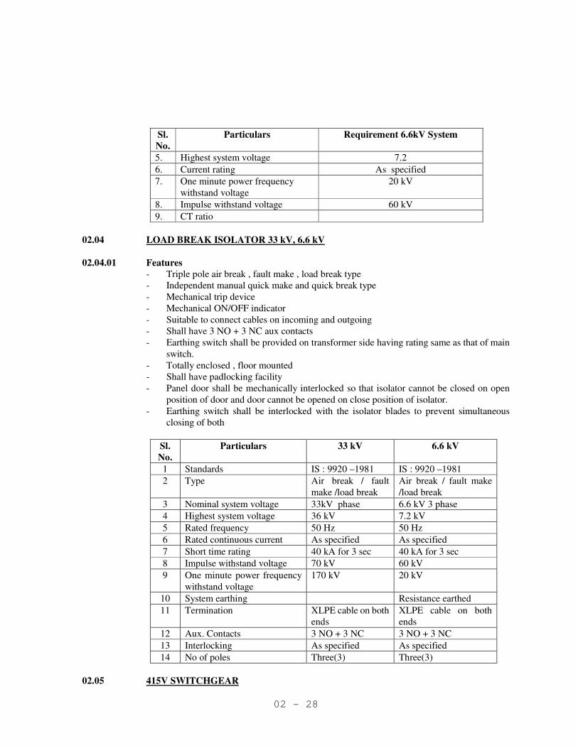
02 - 28
Sl.
No.
Particulars Requirement 6.6kV System
5. Highest system voltage 7.2
6. Current rating As specified
7. One minute power frequency
withstand voltage
20 kV
8. Impulse withstand voltage 60 kV
9. CT ratio
02.04 LOAD BREAK ISOLATOR 33 kV, 6.6 kV
02.04.01 Features
- Triple pole air break , fault make , load break type
- Independent manual quick make and quick break type
- Mechanical trip device
- Mechanical ON/OFF indicator
- Suitable to connect cables on incoming and outgoing
- Shall have 3 NO + 3 NC aux contacts
- Earthing switch shall be provided on transformer side having rating same as that of main
switch.
- Totally enclosed , floor mounted
- Shall have padlocking facility
- Panel door shall be mechanically interlocked so that isolator cannot be closed on open
position of door and door cannot be opened on close position of isolator.
- Earthing switch shall be interlocked with the isolator blades to prevent simultaneous
closing of both
Sl.
No.
Particulars 33 kV 6.6 kV
1 Standards IS : 9920 –1981 IS : 9920 –1981
2 Type Air break / fault
make /load break
Air break / fault make
/load break
3 Nominal system voltage 33kV phase 6.6 kV 3 phase
4 Highest system voltage 36 kV 7.2 kV
5 Rated frequency 50 Hz 50 Hz
6 Rated continuous current As specified As specified
7 Short time rating 40 kA for 3 sec 40 kA for 3 sec
8 Impulse withstand voltage 70 kV 60 kV
9 One minute power frequency
withstand voltage
170 kV 20 kV
10 System earthing Resistance earthed
11 Termination XLPE cable on both
ends
XLPE cable on both
ends
12 Aux. Contacts 3 NO + 3 NC 3 NO + 3 NC
13 Interlocking As specified As specified
14 No of poles Three(3) Three(3)
02.05 415V SWITCHGEAR
02 - 29
02.05.01 General
• Metal clad, indoor type floor mounted, single tier for incomers, bus couplers, and out going
ACB feeders in fully drawout execution.
• Sheet steel shall be CRCA of minimum 2.0 mm thickness.
• Circuit breaker shall be mounted on fully drawout truck with service, test and isolated
positions and complete with following safety interlocks and safety shutters with padlock
facility :
⇒ It shall not be possible to move the truck in or out of cubicle when the breaker is
closed.
⇒ CB compartment door shall be mechanically interlocked so that it will not be
possible to close the CB in plug position when the door is open.
⇒ It shall not be possible to push the truck in close position if either of the safety
shutter is not free and not in close position.
• The position of various control switches, push buttons, levers etc. requiring manual
operation, shall be at a height not less than 450mm and shall not exceed 1850mm from the
finished floor level.
• Name plate for each incoming buscoupler, and outgoing feeder at front and back, both on
the fixed portion of the panel.
• All panels shall have space heater with switch and cubicle illumination lamp with door
switch
• All breakers of similar rating shall be interchangeable.
02.05.02 Insulation Level
• Rated insulation voltage 650 V
• One minute power frequency withstand voltage :
⇒ 2.5 kV for power circuits
⇒ 2 kV for control circuits
• Clearance in air (minimum) :
⇒ Phase to phase - 25.4 mm
⇒ Phase to earth - 19.0 mm
02.05.03 Short Circuit Strength
• Rated short time withstand current not less than the system short circuit level specified
for 1 sec.
• Rated peak withstand current not less than 2.1 times the system short circuit level.
02.05.04 Busbars
• Busbars made of EC grade aluminium alloy equivalent to E91E WP as per IS 5082, 1981,
size adequate for specified rated continuous and SC current.
• Three phase, neutral (with atleast 50% rating of main buses) and continuous earth bus. Bus
bar shall be provided with proper grade & colour of heat shrinkable sleeve.
• Rating of horizontal buses shall be same as that of incomer circuit breakers and vertical run
shall be same as that of outgoing breaker rating
• Temperature rise of bus bars shall not be more than 40 deg. C above an ambient of 50 deg.
C
02.05.05 Protection Requirements
• One auxiliary relay for each transformer incipient faults :

02 - 30
a) Buchholz - alarm (63X)
b) Oil temp. high alarm (490X)
c) Winding temperature high alarm (49 X)
d) Buchholz trip (63Y)
e) Oil temp. high - trip (490Y)
f) Winding temp. high trip (49Y)
• For the above faults, contacts to be made available for inter tripping primary side breaker
also.
• All other protections as specified.
02.05.06 Construction Features (Mechanical Design)
• Sheet steel clad, floor mounted, free standing design, non-dust proof construction
⇒ Extension bus links properly spaced for terminating single cables of size 120 sq. mm
and above as well as for terminating multiple cables of all sizes.
⇒ Where more than one cable have to be terminated per unit, the arrangement shall permit
connection and disconnection of individual cables separately without disturbing other
cables.
⇒ Double, compression type brass cable glands and crimping type, tinned, heavy duty
copper lugs suitable for the type, size and number of cables to be terminated, to be
supplied with the switchboard for all LT power and control cables.
⇒ The interior of the switchboard shall be finished with ‘OFF WHITE’ paint shade.
⇒ All the panels shall be of uniform depth.
⇒ All panels shall be supplied with base channels.
02.05.07 Relays
• Flush mounted
• Mechanically operated flag indicators with all relays capable of being reset without opening
casing
• Shall withstand impulse voltage in accordance with IS/IEC recommendation.
• Test facility by plug from panel front.
• CT secondary shall be shorted on relay withdrawal.
• Diagram plate at the back of case to identify connections.
• The relay shall be microprocessor based numerical and communicable type.
02.05.08 CIRCUIT BREAKER
02.05.08.01 Electrical Features
• Air break triple pole drawout type conforming to IS 13947.
• Rated continuous current as specified.
• Symmetrical breaking capacity and 1 second rating of the breaker not less than the system
short circuit level specified.
• Performance category : P2
• Auxiliary contacts : 6 NO + 6 NC minimum, convertible from NO to NC
and vice versa at site.
Ratings :
Continuous 10 amps
AC 11 4 amps at 240 V
DC 11 0.5 amps at 110 V

02 - 31
02.05.08.02 Operating Mechanism
• Manual or power operated mechanism as applicable
• Spring charged stored energy mechanism to ensure high speed closing and tripping
independent of the operating forces.
• Anti pumping and trip free feature
• Emergency tripping by mechanically operated trip push button (shrouded to prevent
accidental closing) acting directly on the trip bar.
• Closing operation of the breaker to charge the tripping spring, ready for tripping.
• Mechanical indication to show :
⇒ Closing spring charged
⇒ Breaker ON/OFF/TRIP
• Breaker to close only when spring fully charged
• Non-reset type operation counter
• For manually operated breakers.
⇒ Independent manual charging of closing spring and closing by handle.
⇒ Alternatively, closing by mechanical push button with spring previously charged by
handle.
• For electrically operated breakers :
⇒ Charging of closing spring by motor
⇒ closing by closing coil
⇒ spring charging motor and closing coil suitable for rated control voltage (240 AC unless
otherwirse specified).
⇒ One opening and one closing operation without control supply.
⇒ Provision also for manual closing with spring charging motor automatically decoupled
as soon as charging handle is inserted.
02.05.08.03 Drawout Features
• 3 distinct positions viz. service, test, and isolated with the door closed.
• Mechanical position indication and locking/latching facility for all 3 positions.
• Power connections - self aligning, plug-in type.
• Control connections - sliding or plug socket type, mechanically coded, to prevent wrong
insertion, continuous rating 16 amps minimum.
• Automatic safety shutters to prevent accidental contact with live parts when the breaker is
withdrawn.
02.05.08.04 Safety Interlocks
• It shall not be possible to close the breaker in any intermediate position other than the 3
fixed positions.
• With the breaker closed, it shall not be possible to rack it in from any of the 3 position to
another.
• Mechanical stopper to prevent accidental falling while withdrawing.
• It shall not be possible to rack in the breaker from isolated to 'test' position with the door
open together with provision for defeat of this interlocking, however, it shall be possible to
close the door only when the breaker is brought back to 'isolated' position.
• It shall be possible to open the door only when
⇒ breaker is OFF and
⇒ is in 'Isolated' position.

02 - 32
• Remote closing of breaker is not permitted with door open.
• Insertion of breaker into 'Service' position shall not be possible if the shutters are not free.
02.05.08.05 Internal Control Wiring
• Control wiring by 1100V grade PVC insulated, single core copper conductor of minimum
cross section 2.5 sq. mm
• Flexible wires, protected against mechanical damage for wiring to door-mounted devices.
• Wires identified at each end in accordance with schematic diagrams by interlocked type
ferrules.
• Colour code for control wiring :
AC – black Earth wire - Green
DC – light grey Trip circuit - Red
• All connections external to a feeder, all the auxiliary contacts of the LT breaker, and all
spare contacts of the relays shall be wired on to the terminal blocks.
• Interconnection between panels of adjacent shipping sections to be brought out to a separate
terminal block, wires for interconnection properly labeled, looped and bunched inside the
panel for connection at site.
• Not more than two connections shall be carried out on one terminal. 02.05.08.06 External Terminations
001 Control Terminations
• 650V grade multiway terminal blocks of non-tracking moulded plastic complete with
insulated barriers, stud type terminals, washers, nuts and lock nuts and identification strips.
• Power and control terminals segregated.
• Control terminals of minimum rating 10 amps suitable to receive 2.5 sq. mm copper
conductor.
• 20% spare terminals in each control terminal block.
002 Power Terminations
• Suitable for accepting cables/bus trunking as specified in the technical particulars.
• All spare contacts wired upto terminal block of the panels
a) Protective relays - with drawable type
b) auxiliary, timer relays - fixed type
02.05.09 Indicating Instruments
• Taut band type
• Size
Incomer and sectionalizer 144 sq. mm
Outgoing 96 sq. mm
• Flush mounting : in front of the cubicle
• Accuracy class - 1.0
• Ammeters shall be compatible with CTs of 5A secondary and read actual currents.
• For motor feeders ammeters shall have suppressed scale upto 6 times of full load current
after 1.2 times of full load current and shall have red mark on full load value.
02.05.10 Protective Devices
All control circuits shall be individually fed by MCBs with built in thermal and magnetic
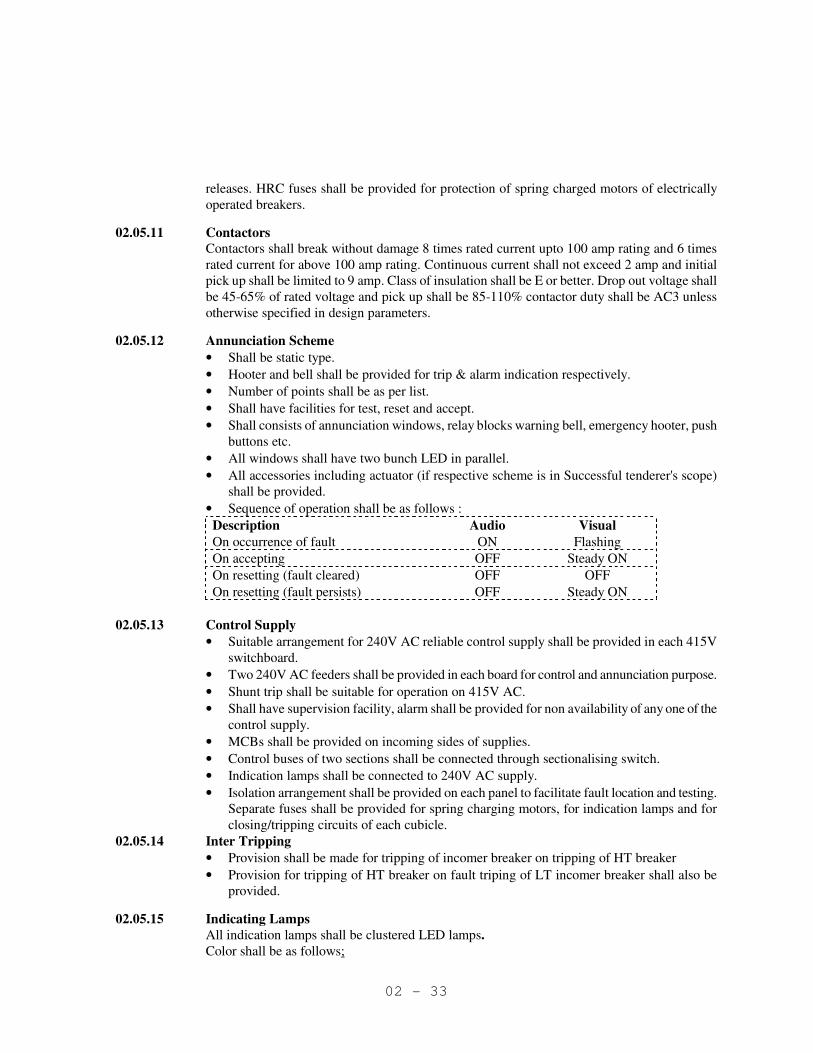
02 - 33
releases. HRC fuses shall be provided for protection of spring charged motors of electrically
operated breakers.
02.05.11 Contactors
Contactors shall break without damage 8 times rated current upto 100 amp rating and 6 times
rated current for above 100 amp rating. Continuous current shall not exceed 2 amp and initial
pick up shall be limited to 9 amp. Class of insulation shall be E or better. Drop out voltage shall
be 45-65% of rated voltage and pick up shall be 85-110% contactor duty shall be AC3 unless
otherwise specified in design parameters.
02.05.12 Annunciation Scheme
• Shall be static type.
• Hooter and bell shall be provided for trip & alarm indication respectively.
• Number of points shall be as per list.
• Shall have facilities for test, reset and accept.
• Shall consists of annunciation windows, relay blocks warning bell, emergency hooter, push
buttons etc.
• All windows shall have two bunch LED in parallel.
• All accessories including actuator (if respective scheme is in Successful tenderer's scope)
shall be provided.
• Sequence of operation shall be as follows :
Description Audio Visual
On occurrence of fault ON Flashing
On accepting OFF Steady ON
On resetting (fault cleared) OFF OFF
On resetting (fault persists) OFF Steady ON
02.05.13 Control Supply
• Suitable arrangement for 240V AC reliable control supply shall be provided in each 415V
switchboard.
• Two 240V AC feeders shall be provided in each board for control and annunciation purpose.
• Shunt trip shall be suitable for operation on 415V AC.
• Shall have supervision facility, alarm shall be provided for non availability of any one of the
control supply.
• MCBs shall be provided on incoming sides of supplies.
• Control buses of two sections shall be connected through sectionalising switch.
• Indication lamps shall be connected to 240V AC supply.
• Isolation arrangement shall be provided on each panel to facilitate fault location and testing.
Separate fuses shall be provided for spring charging motors, for indication lamps and for
closing/tripping circuits of each cubicle.
02.05.14 Inter Tripping
• Provision shall be made for tripping of incomer breaker on tripping of HT breaker
• Provision for tripping of HT breaker on fault triping of LT incomer breaker shall also be
provided.
02.05.15 Indicating Lamps
All indication lamps shall be clustered LED lamps.
Color shall be as follows;
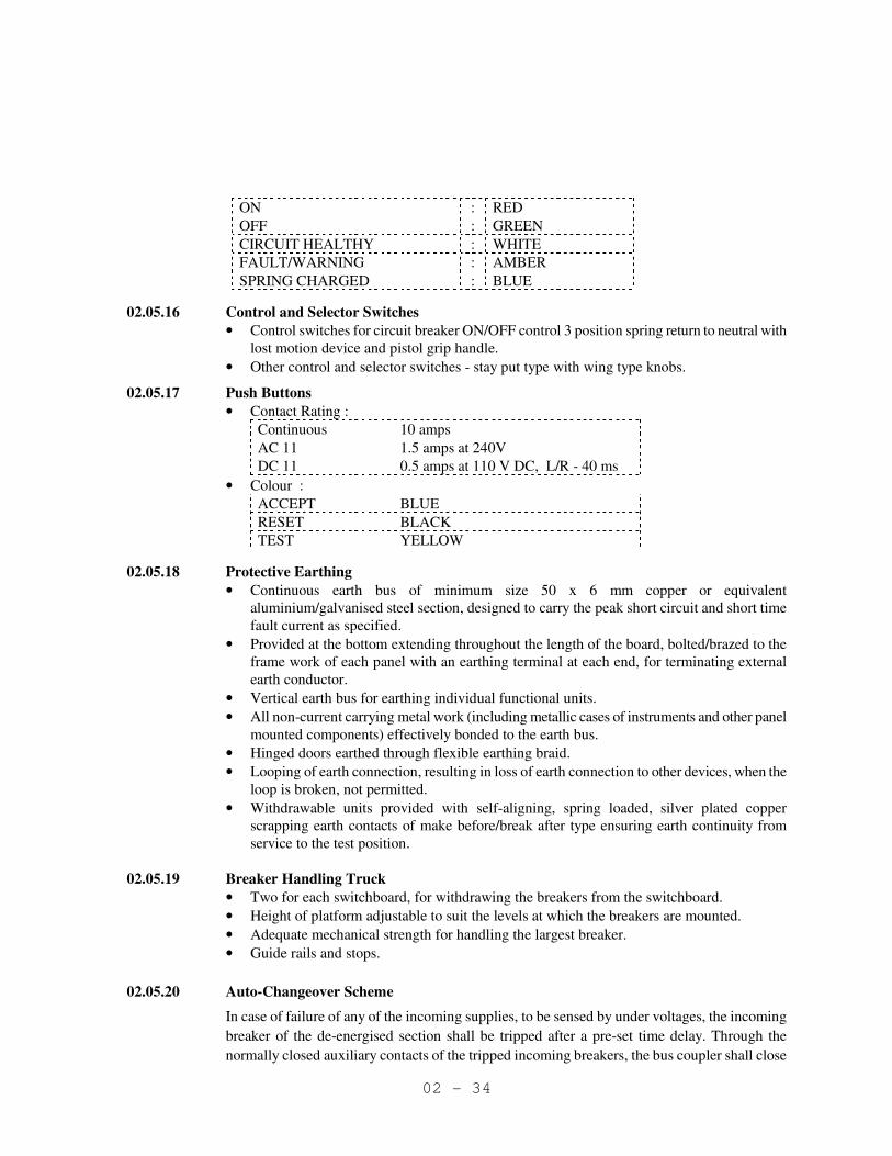
02 - 34
ON : RED
OFF : GREEN
CIRCUIT HEALTHY : WHITE
FAULT/WARNING : AMBER
SPRING CHARGED : BLUE
02.05.16 Control and Selector Switches
• Control switches for circuit breaker ON/OFF control 3 position spring return to neutral with
lost motion device and pistol grip handle.
• Other control and selector switches - stay put type with wing type knobs.
02.05.17 Push Buttons
• Contact Rating :
Continuous 10 amps
AC 11 1.5 amps at 240V
DC 11 0.5 amps at 110 V DC, L/R - 40 ms
• Colour :
ACCEPT BLUE
RESET BLACK
TEST YELLOW 02.05.18 Protective Earthing
• Continuous earth bus of minimum size 50 x 6 mm copper or equivalent
aluminium/galvanised steel section, designed to carry the peak short circuit and short time
fault current as specified.
• Provided at the bottom extending throughout the length of the board, bolted/brazed to the
frame work of each panel with an earthing terminal at each end, for terminating external
earth conductor.
• Vertical earth bus for earthing individual functional units.
• All non-current carrying metal work (including metallic cases of instruments and other panel
mounted components) effectively bonded to the earth bus.
• Hinged doors earthed through flexible earthing braid.
• Looping of earth connection, resulting in loss of earth connection to other devices, when the
loop is broken, not permitted.
• Withdrawable units provided with self-aligning, spring loaded, silver plated copper
scrapping earth contacts of make before/break after type ensuring earth continuity from
service to the test position.
02.05.19 Breaker Handling Truck
• Two for each switchboard, for withdrawing the breakers from the switchboard.
• Height of platform adjustable to suit the levels at which the breakers are mounted.
• Adequate mechanical strength for handling the largest breaker.
• Guide rails and stops.
02.05.20 Auto-Changeover Scheme
In case of failure of any of the incoming supplies, to be sensed by under voltages, the incoming
breaker of the de-energised section shall be tripped after a pre-set time delay. Through the
normally closed auxiliary contacts of the tripped incoming breakers, the bus coupler shall close
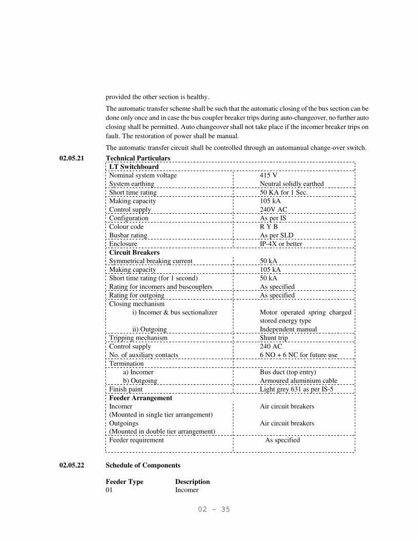
02 - 35
provided the other section is healthy.
The automatic transfer scheme shall be such that the automatic closing of the bus section can be
done only once and in case the bus coupler breaker trips during auto-changeover, no further auto
closing shall be permitted. Auto changeover shall not take place if the incomer breaker trips on
fault. The restoration of power shall be manual.
The automatic transfer circuit shall be controlled through an automanual change-over switch.
02.05.21 Technical Particulars
LT Switchboard
Nominal system voltage 415 V
System earthing Neutral solidly earthed
Short time rating 50 KA for 1 Sec.
Making capacity 105 kA
Control supply 240V AC
Configuration As per IS
Colour code R Y B
Busbar rating As per SLD
Enclosure IP-4X or better
Circuit Breakers
Symmetrical breaking current 50 kA
Making capacity 105 kA
Short time rating (for 1 second) 50 kA
Rating for incomers and buscouplers As specified
Rating for outgoing As specified
Closing mechanism
i) Incomer & bus sectionalizer Motor operated spring charged
stored energy type
ii) Outgoing Independent manual
Tripping mechanism Shunt trip
Control supply 240 AC
No. of auxiliary contacts 6 NO + 6 NC for future use
Termination
a) Incomer Bus duct (top entry)
b) Outgoing Armoured aluminium cable
Finish paint Light grey 631 as per IS-5
Feeder Arrangement
Incomer
(Mounted in single tier arrangement)
Air circuit breakers
Outgoings
(Mounted in double tier arrangement)
Air circuit breakers
Feeder requirement
As specified
02.05.22 Schedule of Components
Feeder Type Description
01 Incomer

02 - 36
02 Bus Coupler
03 Outgoing Feeder
Feeder types Sl.
No.
Schedule of components equipment
specification 01 02 03
1. 415V, 50 kA air circuit breaker with:
- independent manual/motor operated
spring charged mechanism with
- shunt trip/microprocessor released
- Mechanical ON/OFF indicator as
specified below:
1.a - Motor operated ACB with
microprocessor based direct acting O/C,
S/C & EF release with timer
1 1 -
1.b. Manual operated ACB with
Microprocessor based direct acting O/C,
S/C & EF release with timer
- - 1
2. Control switch ON/OFF with spring return
to neutral
1 1 1
3. Voltmeter with selector switch 1 - -
4. Ammeter with selector switch 1 1 1
5. Selector Switch - - -
6. Digital Multi function meter with
communication port
1
7. kWh meter 1
8. Single core current transformer class 1.0
for metering
3 3 3
9. Numerical inverse time over current relay,
setting 10-40% for back up earth fault
protection.
1 - -
10. ON/OFF/Trip on fault/Trip circuit healthy
lamps
4 4 3
11. Auxiliary relays flag indication for
buchholz trip and alarm and oil
temperature trip and alarm signals and
winding temp. alarm and trip signals
- 6 -
12. Auto changeover scheme with under
voltage relay, PT etc.
As per requirement
13. Set of relays, contactors, timers, etc. for
annunciation scheme
As per requirement
14. Set of relays, contactors, timers for auto
changeover scheme
As per requirement
15. Annunciators with required no. of
windows (set)
1 1 -
16. 415/240V, 2.5 kVA Control transformer 2 nos. of control transformer for
two section
17. Impulse switch for tripping 6.6 kV breaker 1 - -
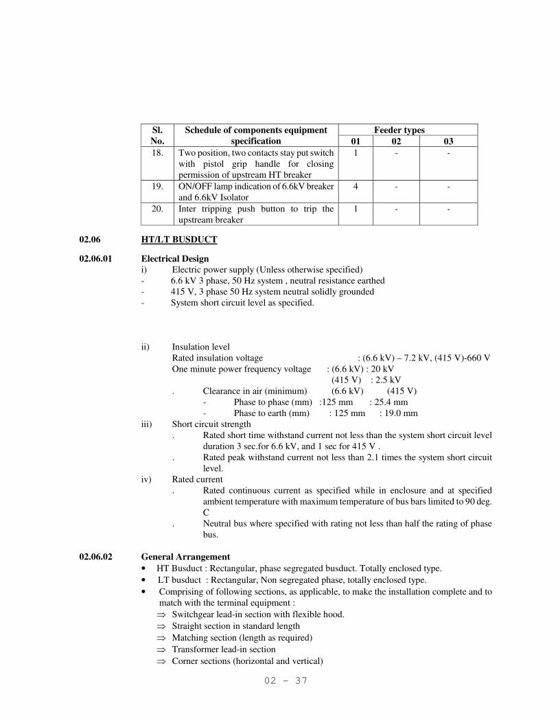
02 - 37
Feeder types Sl.
No.
Schedule of components equipment
specification 01 02 03
18. Two position, two contacts stay put switch
with pistol grip handle for closing
permission of upstream HT breaker
1 - -
19. ON/OFF lamp indication of 6.6kV breaker
and 6.6kV Isolator
4 - -
20. Inter tripping push button to trip the
upstream breaker
1 - -
02.06 HT/LT BUSDUCT
02.06.01 Electrical Design
i) Electric power supply (Unless otherwise specified)
- 6.6 kV 3 phase, 50 Hz system , neutral resistance earthed
- 415 V, 3 phase 50 Hz system neutral solidly grounded
- System short circuit level as specified.
ii) Insulation level
Rated insulation voltage : (6.6 kV) – 7.2 kV, (415 V)-660 V
One minute power frequency voltage : (6.6 kV) : 20 kV
(415 V) : 2.5 kV
. Clearance in air (minimum) (6.6 kV) (415 V)
- Phase to phase (mm) :125 mm : 25.4 mm
- Phase to earth (mm) : 125 mm : 19.0 mm
iii) Short circuit strength
. Rated short time withstand current not less than the system short circuit level
duration 3 sec.for 6.6 kV, and 1 sec for 415 V .
. Rated peak withstand current not less than 2.1 times the system short circuit
level.
iv) Rated current
. Rated continuous current as specified while in enclosure and at specified
ambient temperature with maximum temperature of bus bars limited to 90 deg.
C
. Neutral bus where specified with rating not less than half the rating of phase
bus.
02.06.02 General Arrangement
• HT Busduct : Rectangular, phase segregated busduct. Totally enclosed type.
• LT busduct : Rectangular, Non segregated phase, totally enclosed type.
• Comprising of following sections, as applicable, to make the installation complete and to
match with the terminal equipment :
⇒ Switchgear lead-in section with flexible hood.
⇒ Straight section in standard length
⇒ Matching section (length as required)
⇒ Transformer lead-in section
⇒ Corner sections (horizontal and vertical)
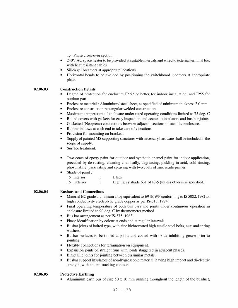
02 - 38
⇒ Phase cross-over section
• 240V AC space heater to be provided at suitable intervals and wired to external terminal box
with heat resistant cables.
• Silica gel breathers at appropriate locations.
• Horizontal bends to be avoided by positioning the switchboard incomers at appropriate
place.
02.06.03 Construction Details
• Degree of protection for enclosure IP 52 or better for indoor installation, and IP55 for
outdoor part.
• Enclosure material : Aluminium/ steel sheet, as specified of minimum thickness 2.0 mm.
• Enclosure construction rectangular welded construction.
• Maximum temperature of enclosure under rated operating conditions limited to 75 deg. C
• Bolted covers with gaskets for easy inspection and access to insulators and bus bar joints.
• Gasketted (Neoprene) connections between adjacent sections of metallic enclosure.
• Rubber bellows at each end to take care of vibrations.
• Provision for mounting on brackets.
• Supply of painted MS supporting structures with necessary hardware shall be included in the
scope of supply.
• Surface treatment.
• Two coats of epoxy paint for outdoor and synthetic enamel paint for indoor application,
preceded by de-rusting, cleaning chemically, degreasing, pickling in acid, cold rinsing,
phosphating, passivating and spraying with two coats of zinc oxide primer.
• Shade of paint :
⇒ Interior : Black
⇒ Exterior : Light grey shade 631 of IS-5 (unless otherwise specified)
02.06.04 Busbars and Connections
• Material EC grade aluminium alloy equivalent to E91E WP conforming to IS 5082, 1981;or
high conductivity electrolytic grade copper as per IS-613, 1984.
• Final operating temperature of both bus bars and joints under continuous operation in
enclosure limited to 90 deg. C by thermometer method.
• Bus bar arrangement as per IS-375, 1963.
• Phase identification by colour at ends and at regular intervals.
• Busbar joints of bolted type, with zinc bichromated high tensile steel bolts, nuts and spring
washers.
• Busbar surfaces to be tinned at joints and coated with oxide inhibiting grease prior to
jointing.
• Flexible connections for termination on equipment.
• Expansion joints on straight runs with joints staggered in adjacent phases.
• Bimetallic joints for jointing between dissimilar metals.
• Busbar support insulators of non-hygroscopic material, having high impact and di-electric
strength, with an anti-tracking contour.
02.06.05 Protective Earthing
• Aluminium earth bus of size 50 x 10 mm running throughout the length of the busduct,

02 - 39
positively connected to the body of the busduct.
• Provision at each end of busduct for terminating external earth conductor.
02.06.06 Technical particulars for Design
Sl.
No.
Particulars 415 V 6.6 kV
1. Application Indoor Indoor
2. Rated system voltage and frequency 415 V 6.6 kV
3. System earthing Solidly earthed Resistance
earthed
4. Rated continuous current as specified
ambient conditions ( in enclosure)
As specified As specified
5. Rated short time withstand current
(kA.rms) and its duration
50 kA for 1Sec 40 kA for 3 Sec.
6. Rated peak withstand current (peak) 105 kA 100 kA
7. Temp rise over ambient of 50 deg. C
- Busbars
- Enclosure
40 deg. C
25 deg. C
40 deg. C
25 deg. C
8. Busbar material Aluminium Aluminium
9. Neutral bus To be provided -
10. Earth bus material Aluminium Aluminium
11. Earth bus size 50 x 10 50 x 10
12. Supporting insulators SMC/ FRP SMC/FRP
13. Busduct enclosure material Aluminium Aluminium
14. Busduct enclosure material thickness 2.5 mm 5.0 mm
14. Busduct support structure To be provided To be provided
02.07 BATTERY, BATTERY CHARGER AND DC DISTRIBUTION BOARD
02.07.01 STANDARD
a. IS-1651 Stationary cells and batteries, lead acid type (with tubular positive
plates)
b. IS-1652 Stationary cells and batteries, lead acid type (with tubular positive
plates)
c. IS-10918 Vented type nickel cadmium batteries
d. IS-8320 General requirements and method of test for lead acid storage batteries
e. IS-7204 Stabilised power supplies DC output
(Part 1 to 4)
f. IS-2147 Degree of protection provided by enclosures for low-voltage switchgear
and controlgear
g. IS-13703 L.V. fueses
(Part 1 to 4)
h. IS-1248 Direct acting indicating analogue electrical
(Part 1,2,9) measuring
i. IS-13947 L.V.switchgear and control gear
(Part 1,3,4,5)
j. IS-12021 Specification for control transformers for switchgear and control gear
for voltages not exceeding 1000 V AC

02 - 40
k. IS-5 Painting
l. IEC-146 Semiconductor converters
m. IEC-178 Stabilized power supplies DC output
Whenever the relevant IS standard is not available , relevant IEC publication shall be followed.
02.07.02 SITE CONDITIONS
The battery chargers shall be suitable for installation and satisfactory operation in a pressurised
substation with restricted natural air ventilation in tropical , humid and corrosive atmosphere.
The battery charges shall be designed to operate under site conditions as specified. If not
specifically mentioned therein, design ambient temperature of 40 deg C and altitude not
exceeding 1000 m above MSL shall be considered with a minimum temperature of 10 deg C for
battery sizing.
02.07.03 GENERAL REQUREMENTS
Battery unit
The battery shall be of the nickel cadmium or lead acid type(Plantetype/VRLA) as specified.
Nickel – Cadmium battery shall be of pocket plate type
Battery containers shall be high quality translucent polypropylene for Nickel cadmium battery
and hard rubber for lead acid battery.
Ampere hour capacity of the battery shall be selected based on minimum site ambient
temperature and discharge duty cycle as specified.. An overall ageing factor of 0.8 shall be
considered for arriving at ampere hour capacity of the battery.
Number of cells and end cell Voltage shall be decided by the vendor on the following basis.
a. Out put voltage shall be limited to max. +10% of nominal system voltage when batteries
are float charged while feeding the load.
b. System output voltage at the end of design duty cycle shall not be less than 90% of
nominal system voltage.
The battery shall be suitable for being boost charged to fully charged condition from fully
discharged condition within 10 hours.
Battery assembly shall be supplied dry and uncharged. Liquid electrolyte shall be delivered with
the battery in suitable sealed containers unless otherwise agreed.
Sets of Indoor Stationary batteries complete with all accessories including but not limited to the
following shall be supplied with each battery set.
a. Battery stand treated first class teakwood assembled without use of any metal fastenings
and coated with 3 coats of anti-acid paint for lead acid battery. Mild steel stand pre-
treated and epoxy painted / PVC coated for Nickel cadmium battery.
b. Intercell, inter now and interbank connectors and end-take-offs. These shall be of lead
plated copper for lead acid battery and tin plated copper for NiCd battery.
c. Cell indulators
d. Stand insulators
e. Required quantity of electrolyte for initial filling of the battery sets with 10% extra in
non-returnable containers.

02 - 41
f. Cell number plates and fixing pins as required
Nominal cell voltage for lead acid battery shall be 2.0V for lead acid batteries and 1.2 V for
Nickel cadmium battery.
02.07.03 Battery Chargers
• Two identical float cum boost chargers, each comprising of :
⇒ MCCB, line contactor, and overload relay on the ac side
⇒ 3 phase full wave semicontrolled rectifier bridge complete with free wheeling diode.
The thyristors and diodes shall have high speed fuses for protection against short
circuits. Necessary snubbers for hole storage effect shall also be provided.
⇒ Filter circuit at the output
⇒ MCCB on DC side
⇒ control and protection circuits.
• In float mode, the charger operates with a constant voltage controller and the output voltage
of the charger shall be maintained within + 1% of the set voltage for
+ 10% input AC voltage variation
or
0 - 100% load variation
or
both occurring simultaneously
The output voltage required can be set externally through potentiometers in the range
90-120% steplessly.
• In boost mode, the charger shall operate with a constant current controller suitable for
two-rate charging. The charging current shall be externally adjustable from 20 to 100%
steplessly.
• Provision of charging with manual control of output voltage shall also be provided.
• During boost charging, the charger shall be cut-off as soon as over voltage occurs.
• Ripple content in the chargers output voltage shall not exceed 0.5% in float mode and 3% in
boost mode.
• The supply to the charger will be at 415V + 6%, 50 Hz + 3% unless otherwise specified.
• The charger shall have voltage rating corresponding to the battery and minimum current
rating as indicated in Technical Particulars for Design. However, the charger rating shall be
chosen to charge the battery from 1.85 volts per cell to fully charged condition in 8 hours.
02.07.04 Relays
• The following relays shall be provided :
⇒ AC input supply to charger failure
⇒ Battery earth fault
⇒ Float bus over and under voltage
⇒ Boost bus over voltage
⇒ Boost over current for each charger circuit
• All relays shall be in drawout cases and with mechanical hand reset operation indicator.
02.07.05 Indicating lamps
• The following indications shall be provided.
⇒ AC supply ON (for 3 phases separately) for each charger

02 - 42
⇒ DC supply ON, for each charger
⇒ Boost/float mode ON, for each charger
⇒ Supply ON, for each outgoing distribution feeder
02.07.06 Metering
• The following measurement shall be provided
⇒ AC input voltage and current, of each charger (through voltmeter/ammeter selector
switches)
• DC output voltage and current, of each charger
⇒ Battery charging/drain current
⇒ Battery trickle charging current (through amplifier)
⇒ DC bus voltage (through selector switch).
02.07.07 Alarm Annunciation
• Annunciation shall be provided for the following :
⇒ Failure of AC supply to charger
⇒ Battery earth fault
⇒ Float bus over/under voltage
⇒ Boost bus over voltage
⇒ Boost over current for each charger
⇒ Failure of thyristor/diodes for each charger
⇒ Failure of blocking diode
⇒ Output MCCB open for each charger
⇒ Battery MCCB open
⇒ Outgoing feeders MCCB open
⇒ Battery room exhaust fan OFF
• The annunciation system shall incorporate solid state facia window type annunciators. The
sequence shall be :
⇒ On incidence of a fault, a hooter will come ON and the corresponding window's lamp
shall start flashing.
⇒ On pressing 'accept' button, hooter shall stop and lamp shall become steady.
⇒ On pressing 'reset' button, the lamp will stay ON if the fault still persists or will go OFF
if the fault has been cleared.
• The power supply for the above annunciations shall be taken from the DC float bus.
• A separate annunciation with an AC hooter shall be provided for DC supply failure. This
annunciation shall be fed from the AC supply. Reset shall be by a stay put push button.
02.07.08 DC Distribution Board
• The DC distribution board shall have double busbar arrangement, viz. one set of the +ve and
-ve connected to charger-1 and another set of +ve and -ve bus connected to charger-2. It
shall be possible to connect the bus bars with either charger through selector switches.
• Indicating instruments shall be as per IS 1248, accuracy class 1.5, 96 x 96 mm size.
• AC meters shall be taut band type, DC meters moving coil type.
• DC meters shall be zero centre type where applicable.
02.07.09 Feeder Arrangement
• Each outgoing circuit shall be connected to both the sets of bus bars through selector switch.
02 - 43
It shall be possible to connect each outgoing circuit to either set of bus bars. Each outgoing
circuit shall have MCCB. The No. of outgoing circuits shall be as per requirement
02.07.10 Construction Features
• The battery chargers and the DC distribution board (including alarm annunciation) may be
integrated into one switchboard or separate boards may be provided.
• Switchboard shall be floor mounting type sheet steel enclosed with degree of protection IP
52 or better.
• Sheet steel used shall be CRCA of minimum 2 mm thickness except for doors and covers for
which 1.6 mm thick shall be used.
• Cable entry shall be from bottom, removable gland plates shall be provided.
• All components shall be mounted above 450 mm and below 1850 mm from the floor level.
02.07.11 Wiring and Terminations
• All power wiring shall be done through single core PVC insulated copper wires/buses.
• All control wiring shall be done through single core, PVC insulated copper wire of 2.5 sq.
mm
• All connections external to the panel/switch board shall be terminated in suitable terminal
blocks. Inter panel wiring shall be only between terminal blocks.
• Each wire shall be identified by ferrules corresponding to the schematic diagram.
02.08 AC DISTRIBUTION BOARD (ACDB)
• 415V, 3 phase, 4 wire, 1000 A, 50 KA (short time rating for 1 second) indoor type.
• Board shall be single front , metal clad, front matched, dust and vermin proof, fully
compartmentalised and extensible on both sides , IP5X type enclosure.
• Shall have base channel of size ISMC75
• Shall have isolated busbar chamber for main busbar at the top, running through out the
length of the board. Chamber shall have removable cover.
• Cable alley shall have sufficient space for aluminum power cables and bottom cable
chamber shall be left free completely isolated from the vertical bubars.
• Busbars shall have same cross section through out the length . Rating of the neutral bus bar
shall be 50% of the main bus bar. Earth bus bar shall run in bottom chamber through out the
length of the panel.
• Shall have Moulded Case Circuit Breaker (MCCB) triple pole , air break type with
independent manual quick make and break type. MCCB shall be capable of breaking rated
current at 0.3 pf at the rated voltage. MCCB shall withstand the fault current envisaged for
415V system.
• All feeders shall have ON/OFF lamps and 96 sq mm size ammeter.
• Shall have 2 incomers & 1 bus coupler .
• Incomer & Bus-coupler shall have manual operated ACBs with Microprocessor based o/c,
short circuit, earth fault & shunt trip releases and out going shall be MCCBs.
02.09 CAPACITOR BANK
02.09.01 Code and Standards
The capacitor banks and accessories offered shall conform to the latest edition of the following
02 - 44
standards:-
IS:2026 Part-2 Specification for power transformers.
IS:2099 Bushings for Alternating voltages above 1000V.
IS:2544 Porcelain post insulators for systems with nominal voltage
greater than 1000V.
IS:2834 Shunt capacitors for power systems.
IS:3156 Parts 1,2 & 3 Voltage transformers.
IS:5553 Parts 1,3,4 & 5 General requirements, current limiting, damping & tuning
reactors.
IS:9402 H.V. Fuses for the external protection of Shunt.
02 - 45
IS:12672 Internal fuses and internal overpressure disconnectors for
shunt capacitors.
IS:13925 Shunt capacitors for AC power systems having a rated
voltage above 660V.
02.09.02 SITE CONDITIONS
The capacitor banks and accessories shall be suitable for installation and satisfactory operation
for indoor application, in a separate room inside substation building, in safe area, in a tropical,
humid and corrosive atmosphere. They shall be designed to operate under site conditions
specified in the requisition/ data sheet. If not specifically mentioned therein, a design ambient
temperature of 40°C and an altitude not exceeding 1000m above mean sea level shall be
considered.
02.09.03 CONSTRUCTION
02.09.03.01 The capacitor banks shall comprise the following basic components. Other equipment, not
specifically listed below not necessary for the safe and proper functioning of the capacitor bank
shall be included.
i) Capacitor units of appropriate kVAR rating.
ii) Series reactor, if specified.
iii) Residual voltage transformer (R.V.T.)
iv) External expulsion type fuses or internal element fuses, as per the manufacturer’s
design.
v) Insulators and bushings.
vi) Cable end boxes for cable termination.
vii) PVC sleeved aluminium busbars for interconnecting the units to form bank and for
interconnecting the series reactor and the R.V.T.
viii) Discharge resistors, if required.
ix) Elevating steel structure.
x) Lighting arrestor, if specified.
xi) Incoming isolator, if specified.
02.09.03.02 The entire capacitor bank with post insulators, series reactor, RVT, lightning arrestor and
incoming isolator shall be supported on steel elevating structures which shall be designed and
supplied by the capacitor supplier.
The steel elevating structure shall be so designed that the bottom most portion of any insulator or
bushing on the assembly shall be at a minimum height of 2.75m above ground level.
The steel elevating structure shall be galvanised. The amount of galvanising shall be minimum
02 - 46
700 gms/m2.
02.09.04 DESIGN FEATURES
02.09.04.01 Capacitor Units
The capacitor banks shall comprise appropriate nos. of basic single phase units (minimum 4 nos.
basic units in parallel per phase) which shall be connected in start formation. In case the kVAR
rating is equal to or below 200kVAR per phase and 4 units per phase cannot be achieved. 1 unit
per phase may be provided. The dielectric shall be all polypropylene or mixed dielectric with low
watt loss. The impregnant in the capacitors shall be non-toxic, non-PCB (Poly chlorinated
biphenyl) based, and bio-degradable.
The capacitor units shall be assembled such that the capacitor banks are capable of withstanding
the electro-dynamic and thermal stresses caused by transient over currents during switching.
Protection for capacitor banks using internal element fuses or external expulsion type fuses shall
conform to the following requirements.
In internal element fuses design, the internal design of series and parallel arrangement of
elements shall be such that.
i. In the case of one failure, there is no harmful over voltage across the remaining
elements.
ii. Operation of a single fuse element does not cause cascade fuse blowing.
iii. Permissible over voltages and surges do not cause fuse blowing.
In the external expulsion type fuse design.
i. Fuse characteristic shall be co-ordinated with capacitor unit characteristics.
ii. Fuse shall be rated to allow inrush current of the capacitor unit.
02.09.04.02 Busbars
All busbars interconnecting the basic units as well as the series reactor and R.V.T. shall be of
electrolytic aluminium and shall be P.V.C. sleeved. All busbar joints shall be shrouded with
removable FRP shrouds.
The sleeves shall be rated to withstand the system line-to-line voltage for 1 minute. This shall be
verified by type test in which the line voltage will be applied between the sleeved main busbar
and an aluminium foil wrapped closely around the insulation over a length of 500mm.
The clearances for 6.6kV capacitor bank systems shall be as follows:
Minimum clearance between phases : 228.6 mm.
Minimum clearance phase to earth : 177.8 mm.
02 - 47
02.09.04.03 Series reactor
Series reactor, if specified, shall be provided to limit the inrush current and to supress the
harmonics. The percentage impedance specified by vendor and if found inadequate, suitable
sized series reactor shall be offered. The series reactor shall be in a weather protected completely
sealed unit.
Series reactor shall be designed to have linear V/I characteristic, at least, upto 150% of rated
current. Temperature rise for oil and winding shall not exceed the limits specified in IS:2026.
Series reactor shall be of oil-immersed, air cored, non-magnetically shielded design, with
conservator.
02.09.04.04 Residual Voltage Transformer (R.V.T.)
A continuously rated voltage transformer for unbalance protection shall be provided with
primary connected in star and the secondary connected in open delta. The secondary voltage
shall be 110/3 Volts, unless otherwise specified.
02.09.04.05 Cable boxes
Cable boxes suitable for high voltage XLPE insulated, aluminium conductor, screened and
overall PVC sheathed cables of sizes specified shall be provided on the series reactor. Cable box
shall be designed to withstand specified primary system fault level for 0.25 seconds. Cable box
for control cable shall be provided on the R.V.T.
All cable boxes shall be weatherproof to IP-55.
02.09.04.06 Insulators and bushings
Bushings shall comply with SI-2099. Creepages for highly polluted environment as per
requirement of the relevant IS shall be provided. The bushing shall be homogenous; free from
lamination, cabities and other imperfections that might affect the mechanical and dielectric
quality and shall be throughly vitrified, tough and impervious to moisture.
02.09.04.07 Discharge resistors
Discharge resistors, if required, shall be provided to reduce the capacitor terminal voltage to a
value equal to or less than 50V in minutes after capacitor is disconnected from the electrical
system.
02.09.04.08 Lighting arrestor and incoming isolator shall be provided, if specified in the datasheet. Isolator
shall be suitable for off-load isolation of the capacitor bank.
02.09.05 Protection of Capacitor Bank
The following protection is proposed to be provided on the circuit breaker controlling the

02 - 48
capacitor banks by the purchaser.
i) IDMTL over-current relay.
ii) IDMTL earth fault relay.
iii) Inverse time-voltage neutral phase displacement relay.
iv) Definite time under voltage relay.
v) Inverse time over voltage relay.
vi) Timer to prevent reclosure of capacitor bank before discharge.
Vendor shall clearly indicate any other protection considered necessary for safe operation of
capacitor bank.
02.09.06 Painting and Marking
The casing of the capacitor for outdoor installation and the frame work shall be painted after
suitable treatment with one cost of anti-rust paint and two coats of epoxy base acid/ alkali
resistant paint. Paint shade shall be 632 of IS:5.
All external bolts and nuts shall be cadmium plated or zinc passivated.
Capacitor banks shall be provided with stainless steel nameplate indicating the rating and all
technical particulars as per IS:2834 and IS:13925. Capacitor, series reactor, R.V.T and external
fuse (if provided) connection diagram shall also shown on the rating cum diagram plate.
Stainless steel nameplates shall be provided to indicate the phase to which each capacitor unit
belongs and its rating.
Capacitor vendor shall ensure that series reactor and R.V.T. shall also be provided with similar
stainless steel nameplates indicating the rating and identifying the terminals clearly.
02.09.07 Engineering
02.09.07.01 Sizing Criteria
The offered capacitor bank conjunction with series reactor will provide minimum net capacitive
KVAR at the rated nominal voltage to maintain the power factor as specified . The vendor shall
size and design the capacitor bank, series reactor and residual voltage transformer for the
maximum continuous over voltage that can appear across each of these elements, considering
system voltage variation given in the data sheets and voltage rise because of series reactor.
Insulation level shall be chosen accordingly.
Series reactor shall be so sized that it is capable the permissible capacitor bank over current, as
specified in the IS for capacitor banks continuously.

02 - 49
If specified, lightning arrestor shall be provided and the rating of the lightning arrestor shall be
equal to the line voltage of the capacitors for ungrounded/ resistance ground systems, it shall be
80% of the line to line voltage of the capacitor. Lightning arrestor shall also have impulse
breakdown voltage (1.2/50 µs test wave) less than 66% of B.I.L. of capacitor bank.
02.09.07.02 Engineering documentation
The manufacturer shall complete the engineering for capacitor usage as detailed below
i) Fuse sizing, in case of external expulsion fuse.
ii) Reactor sizing calculation.
iii) Capacitor bank sizing calculations to show that the net capacitance achieved at the
nominal voltage is as specified in he requisition.
iv) Sizing of lightning arrestor, if provided.
v) Calculations for the inrush current of the capacitor bank considering worst switching
conditions and back conneciton, if applicable.
vi) Fault contribution from the capacitor bank to a short circuit in the system
a. Instantaneous
b. After 5 cycles
02.10 CABLES
02.10.01 General
Types of cables of following grades and general specifications shall be used taking into
consideration the application requirements.
Type-1 33 kV (UE) XLPE cable
33 kV (E) heavy duty power cable, three core, with compact circular stranded (rm/V) aluminum
conductor, with extruded conductor shielding of semi conducting material, XLPE insulated, with
insulation shielding over individual cores, consisting of extruded semi conducting compound,
followed by lapped semi conducting material and copper tape, cores stranded together with a
holding tape provided with a common covering of extruded inner sheath of type ST2 compound,
galvanized steel wire armoured and FRLS outer sheathed as per latest IS, as amended upto date.
Copper screen shall be suitable to carry 1 kA E/F current for one second.
Type 2 : 6.6 kV (UE) XLPE cables
6.6 kV (UE) heavy duty power, cables 3 core, with compact circular stranded (rm/V) aluminum
conductor, with extruded conductor shielding of semi conducting material, XLPE insulated, with
insulation shielding over individual cores, consisting of extruded semi conducting compound,
followed by lapped semi conducting material and copper tape, cores stranded together with a
holding tape provided with a common covering of extruded inner sheath of type ST2 compound,
galvanized steel wire armoured and FRLS outer sheathed as per latest IS, as amended upto date.
Copper screen shall be suitable to carry 1 kA E/F current for one second.

02 - 50
Type 4 : 1.1 kV, PVC aluminum power cables
1.1 kV, heavy duty power cable multicore with standard sector shaped (sm) or with compact
circular stranded (rm/V) or circular stranded (rm) aluminum conductors as applicable, HR PVC
insulated of type PVC compound suitable for 85 deg.C. operation as per IS:5831-1970, core
stranded together provided with a common PVC compound, galvanized steel wire armoured and
PVC outer sheathed of type ST2 covering of extruded inner sheath of type ST2 compound
conforming to IS:1554 (Part-I) - 1976, as amended upto date.
Type 5 : 1.1 kV PVC copper control cables
1.1 kV circular stranded (rm) annealed copper conductor, PVC insulated of type A, PVC
compound suitable for 70 deg. C operation as per IS-5831, 1970. Cores shrouded together
provided with common covering of extruded inner sheath of type ST1 PVC compound,
galvanized round steel wire armoured and overall PVC sheathed of type ST1 compound and
multicore to IS : 1554 (Part-I) – 1976.
The number of cores may be standardized as 2,3,4,5,7,10,14,19,24. Each core of control cable
with 7 core and above shall be numbered at every 1 meter intervals.
In multi-core control cables, the following minimum reserve cores shall be kept at the
engineering stage.
Upto 7 cores - One reserve core
10 cores - Two reserve core
14,19, & 24 core - Three reserve core
Sequential length marking shall be provided in outer sheath of all power and control cables.
Standard drum length for all types of power and control cables shall be offered.
ISI marking at every meter of cable length shall be provided.
For all cables, a minimum extra length of 2 metres will be left before jointing.
02.10.02 Cable Joint/termination accessories
The cable accessories shall include end termination kits, straight through joints and also any
special tool and tackles and accessories required for making the joints/terminations.
The straight through joint/termination arrangement shall be complete with all fittings and
consumables. The joint shall have electrical and mechanical withstand capability, same as that of
the associated cable.
The termination kit shall be of heat shrinkable type / push on type.
The termination kits/straight through joints shall have the following features:
• Electrical stress control to be provided at the cable insulation shield terminus.
• An external leakage insulation to be provided between the cable conductors and ground.
• Adequate protection to be provided at the end of the cables against the entrance of the

02 - 51
moisture and, provision to maintain the constant pressure in the cable.
02.11 Earthing and lightning protection
• All metal parts of electrical equipment not intended to be live, transformer neutral, steel
supporting structures for equipment/cables, and fencing of outdoor switchyard shall be
earthed in accordance with the latest IE Rules and IS 3043, 1987,IEEE 80.
• All earthing connections shall be of sufficient section to carry the fault current for 3 seconds.
• Soldered joints shall not be used. All joints shall be welded.
• Earthing system shall be designed to achieve earth resistance of value not exceeding 1 ohm.
• Grounding stations shall be exposed and not buried. These shall be protected from traffic
movement.
• Earth electrodes shall have facilities for measurement of resistance and watering during dry
season.
• The substation building shall be provided with suitable arrangement for lightning protection.
• The LV side neutral of the transformer shall be connected directly to two separate and
distinct earthing electrodes, not forming part of sub-station earthing ring.
• For equipment ground connections, the minimum conductor sizes used should be as follows:
75 x 6 GI flat for :
• Main earthing ring
• Main switchboards HT & LT
• Transformers
• HT Motors
• Earthing leads to earth electrodes
50 x 6 GI flat for :
• Switchboards, Capacitor banks, MCC, PMCC, MLDB etc
Earthing electrodes
The earthing electrodes shall be of GI pipes, 50 mm dia and about 4 mm thickness in one piece,
provided with water holes and water filling funnel. The earth pit design shall confirm to IS:3404-
1987.
02.12 ILLUMINATION
The substation premises shall be provided with illumination facilities to achieve and maintain
the specified illumination levels. Peripheral illumination shall also be provided around the
buildings.
02.12.01 Source of Power Supply
Lighting system shall be supplied at 240V through 415V, 3 phase, 4 wire, 50 Hz AC Supply
system. The incoming supply cables and their connection also forms part of the scope of work.
Source of supply shall be from ACDB located in sub-station building
02.12.02 Control board and Control device
Lighting panel board shall be of sheet steel, dust and vermin proof, heavy duty type. Incoming
feeders shall be provided with MCCBs or switch fuse units. Outgoing sub circuits shall be
controlled by MCBs. Minimum rating of the MCBs shall be 16 Amps, 9 kA. Individual control
switches where ever provided shall be of rotary type. Rating of the busbars shall be one and half
time that of the incoming breaker. All metal enclosure shall be fabricated with at least 2 mm
thick steel. All equipment and accessories mounted outdoor shall be metallic and weather proof
design or shall be enclosed in a weather proof sheet steel enclosure. The enclosure class shall be
IP-54 and IP-55 for control boards to be installed indoor and outdoor respectively. The LDB

02 - 52
shall have two incomers and a sectionalizer, so interlocked that any two can be closed at a time.
The incomer shall be provided with ON/OFF indication lamps.
02.12.03 Cabling/wiring
Wiring shall be carried out with PVC insulated, PVC sheathed, 650/1100 V grade cable with
aluminum conductor in hot deep galvanized rigid sheel conduits or with armoured cable to suit
location . Heavy duty armoured cable shall be used for incoming feeder. Minimum size of cable
shall be 4 sq.mm. Wherever unarmoured cables is used. It shall be taken in galvanized iron
pipes.
02.12.04 Illumination levels
The number of luminaries shall be adequate to achieve and maintain the illumination levels as
indicated below:
Switchgear room - 200 lux
Transformer room - 100 lux
Battery room - 100 lux
Office - 250 lux
Store - 100 lux
Cable basement - 100 lux
02.12.05 Type of fittings
Industrial type low bay fittings with HPMV lamps and 40 W tubular fluorescent lamps shall be
used for illumination of substation premises. Luminaries in battery room shall be vapour proof
type. For peripheral lighting, street light fitting with HPSV lamps shall be used.
Number of light fittings shall be decided on the basis of specified lux level, maintenance factor
and coefficient of utilisation.
The coefficient of utilisation shall be calculated by successful tenderer, based on room sizes.
Maintenance factor should be taken as 0.6-0.7 for both yard and rooms.
02.12.06 Emergency Lighting
Total illumination of the sub-station premises shall be achieved through the lighting DB. For
emergency lighting, additional light fitting in the switchyard, MRS and HT sub-station shall be
supplied from the DCDB to achieve approximately 20% of the specified illumination level.
Portable/ rechargeable hand lamp sets shall also be provided for use in various electrical
premises.
02.12.07 Ceiling Fans/Exhaust Fans
1400 mm sweep celing fans shall be provided for office rooms, stores rooms, other manned
premises and other social buildings. At least 1 no. fan shall be provided for every 10 sq.mtre
area. The ceiling fan shall be complete with electronic regulator.
Exhaust fans of 300 mm switch for toiles, battery room etc. shall be provided with their
control devices (MCBs) and louvers.

02 - 53
02.13 INSTALLATION GUIDELINES
02.13.01 Installation of equipments
- All the electrical installations shall conform to the Indian Electricity Act, Indian
Electricity Rules, and regulations in force in the state by Electrical Inspectorate. All the
items required as per electrical inspectorate shall be included in the scope of work.
These shall be installed by duly licensed and authorised person only.
- The mechanical and other installation shall conform to the applicable Acts and Rules of
corresponding Inspectorate and other relevant authorities, if any.
- All the works under this contract, including the installation of the equipment, shall be
got inspected and approved by the relevant authorities like Electrical Inspectorate etc.
02.13.02 Tools & Tackles
- The Contractor shall provide all tools/tackles jigs and fixtures, winches, alignment tools,
welding sets, testing kits, testing meters/instruments, breaker handling devices, all
consumable items and construction equipments as required to install the work complete
in all respects, and shall necessarily include (but not be limited to) bolts, nuts, rivets,
welding rods, shims, wedges, packing sheets, packing compounds, oil, flushings oil,
protective greases and oils, all materials required for proper installation and protection
of individual equipment in storage and during erection, testing and commissioning.
- This shall also cover proper alignment, tac welding, tagging, laying, marking of, and
connection of cables, fabrication supply and installation of all support structures for
installation of various electrical equipments and cables.
- Provision of cable glands, ferrules, cable lugs, tags, sealing kits (for HT cables) shall be
arranged.
- Supply and installation of first aid boxes, shock treatment charts, rubber mats, and key
board etc.
02.13.03 Erection and Commissioning
- Erection, testing and commissioning of various equipments shall be done strictly as per
manufacturer's instructions.
- Contractor shall submit proposed test procedure to the purchaser for approval well in
advance and shall not commence testing until approval is conveyed.
- All plant and equipment the painting of which has been damaged during
transportation/erection or by corrosion shall be given two coats of paint after removal of
scales rust oil, etc.
- All iron frame work erected shall be provided with the under coat of primer and one top
coat of finish paint.
- Approved type of danger boards, boards inscribing 'ISOLATED', 'DO NOT CLOSE,
MEN AT WORK' shall be provided in sufficient numbers.
- All ventilation and forced draft openings shall have suitable screen protection.
- Special care shall be taken to make the enclosed equipment protected against entry of
rats, lizard, and creeping reptiles which may create electrical short circuits.
02.13.04 Stages of completion of works
The stages of completion of various works shall be as follows :
1. Completion of erection
- Equipment shall be considered to be completely erected when the following
activities have been completed.
- Moving of all equipments to the respective foundations.

02 - 54
- Fixing of anchor bolts or tack welding as required.
- Leveling and alignment of equipment.
- Assembling of all accessories such as relays, CTs, PTs, meters, instruments etc.
as described in the job specification.
- Drying of equipment as required and testing of oil for di-electric strength
- Filtration and filling of oil as required
- Cable laying, termination with continuity check.
- Applying of finishing coat of paint
- Mounting of lighting fixtures and connections.
- Completion of earthing system.
02.13.05 Cable Installation
001 Mode of cable installation
Interplant cable shall be laid in trenches, tunnel or on overhead structures as per site conditions.
Digging and refilling of cable trenches, required erection accessories shall be in the scope of
work. In the substation and MRS cables shall be laid in concrete channels or basement.
002 Trenches
The maximum depth of all trenches shall normally be 1.0 meters, with 750mm cover above the
protective slabs, unless otherwise agreed. The back filling of the excavation shall be carried out
without disturbing the cover slabs or damaging the cables. 003 Cable laying in trenches
The cables shall be laid on 8 cms of riddled sand and approved protective slabs of reinforced
concrete. Unless agreed otherwise, all power cables shall be spaced 15cms apart, horizontally.
004 Cable markers
Approved cable markers of reinforced concrete shall be provided and fixed to mark each and
every deviation of all buried cable routes. A marker shall also be placed every 50 metres along
straight through part of each route. A concrete cable marker shall also be provided and fixed to
mark the position of every buried joint.
005 Cable fixing
Cable shall be fixed to cable racks or cable trays or run on cleats or in conduits, which shall be
fixed to concrete brick work or steel structure as required for proper support of the cables, easy
accessibility and neatness of appearance.
All necessary frame works and fixings for the support of cables and accessories shall be supplied
and fixed by the electrical contractor.
Each cable run shall have to be approved before installation commences. Openings in walls and
floors if not already provided shall be made. The openings shall be properly sealed, after drawing
the cables.
006 Supporting steel work for outdoor switchyard equipment
All supporting steel work shall be free from dirt, rust or scales and shall be galvanised.
007 Cable supporting Structures
The structures shall be painted. Power cable shall be supported at 750 mm interval on cable
racks and control cables shall be supported on perforated cable trays.
Cables shall be laid in separate racks according to voltage levels. Horizontal clearance not less
02 - 55
than diameter of bigger cables shall be provided between two cables.
008 Fixing to concrete and brick work
The cable supporting material shall be fixed to concrete and brick work by the use of rawl bolts
and rawl plugs. Fibre plugs shall not be used.
009 Cables in conduits
Cable conduits, pipes or luck guards shall be provided to protect the cables, where the cables rise
through holes at ground level.
Cables shall be laid in conduits upto 2 meters height above the floor in case of vertical run to
avoid mechanical damage.
Not more than one cable shall be drawn into one conduit unless agreed otherwise.
Maximum cross section areas of cable passing through conduit shall not exceed 60% of cross
section of conduit.
After the cable has been drawn in the conduit, the same shall be sealed by approved means.
010 Cable terminations
The cables shall be terminated in accordance with the relevant diagrams. The cable cores from
the sealing box or gland to the terminals of the apparatus shall be neatly arranged, and shall be of
sufficient length to prevent the development of tension or local pressure on the insulation. They
shall be suitably supported as required.
011 Identification and Marking
Each end of each core of every control cable shall be fitted with tight ferrules of approved make
and shall be of white inflammable plastic insulation material, having the marking engraved in
black to correspond with the relevant diagram. Where the ends of one conductor have different
markings each end shall also have white ferrules engraved in red with the remote marking.
Each ferrule shall have its number engraved 3 times around the periphery, 120 deg. apart.
The cores of each power cable other than distribution cable shall be identified in accordance with
the relevant diagram by means of labels secured to each core.
Distinguishing labels of non-corrodible material marked in accordance with the cable numbers of
the cabling diagram shall be permanently attached to each end of every cable. The phase or
polarity of each power cable core at the cable ends shall be identified as follows :
AC system Phases - Red, yellow and blue painted discs
Neutral - Black painted disc
012 Connection to terminals
Power cable connections shall be made with cable lugs of approved type and material taking into
account the bimetallic actions.
All control circuit connections shall be made with the bare conductor with the use of rose
courtenay type washers, crimped lugs, etc. The ends of all stranded conductors shall be twisted
tightly together. Solid or stranded conductor shall be connected to terminal studs by taking one
complete turn around the stud between the flat washers.
013 Protection of cables
All cables shall be installed in such a manner that the risk of subsequent damage is minimised.
Steel guards shall be provided where necessary

03 - 1
03 SHOP ELECTRICS
03.01 MOTORS & FIELD DEVICES
03.01.01 Low voltage squirrel cage induction motors:
The Motors shall conform to IPSS: 1-03-001 & IS 325 – 19..
001 Constructional features:
− Frame sizes and ratings and other facilities as per IPSS
− For motor body shall be of grey iron casting as per IS:210-1978
− The motor feet shall be integrally cast with the stator and shall be such a design as to
prevent breakage or other failures due to vibrations normally encountered in heavy
industries.
− Degree of protection for motor & bearings to be IP-54 and IP55 for terminal box.
− Cylindrical shaft ends, unless otherwise specified
− Shaft extension as per requirement.
− For motor of rating upto 5 kW, roller bearings shall be used for both DE & NDE end.
For ratings above 5 kW the DE end shall be provided with roller bearing and NDE end
shall be provided with ball bearing.
− Bearings shall be suitable for running of motor in either direction.
− Explosion proof/increased safety design for explosion hazardous areas as per
requirement.
002 Terminal box:
− Terminal box amply dimensioned to receive aluminium cables and provided normally
on the right side as viewed from drive side or on the top as per the requirement.
− Terminal box frame with opening for cable rotatable by 4x90 deg.
− A suitable earthing stud shall be mounted inside the terminal box.
− Terminal Box shall be suitable to receive the aluminium cables as given in Table-I.

03 - 2
− Extension of Terminal box as required shall be done to receive the Aluminium cables to
avoid cramping of the cables in the terminal box.
003 Cooling:
- Motors shall be of TEFC design
- Ventilation shall be effective irrespective of direction of rotation.
004 Quality of Operation:
- Motors shall be dynamically balanced with full key on the shaft- end and fan.
- Vibration intensity shall be limited as per IS 12075-1986.
- Noise level should be as per IS: 12065-1987.
005 Electrical Design
- Suitable for DOL starting
- Motors capable to start and run-up at a minimum of 85% of rated voltage at its
terminals with the driven mechanism/equipment connected.
- Starting torque shall be not less than 160% of rated torque.
- Starting current shall be less than or equal to six times the rated current.
- Continuous duty motors shall be capable of three equally spread starts per hour under
normal condition or two starts in quick succession from cold or one hot start, under
rated load condition.
- Designed for 150% rated speed for 2 minutes.
- In case of VVVF control, suitable derating shall be considered while selecting motor
rating and frame size.
- Motors shall have class ' F' insulation. Minimum Permissible temperature rise of
winding shall be limited to 80 deg. C above ambient temperature of 40 deg.C as
measured by resistance method.
- Motors selected shall be of normal starting torque type, high starting torque type, high
slip type or stall torque type as required for the specific application.
03 - 3
- Space heaters shall be provided for all outdoor motors rating above 37kW.
- Four pole motors to be used for all general applications, unless specific drive
requirement or economics call for other poles.
03.01.02 Low Voltage Slip Ring Induction Motors
The Motors shall conform to IPSS: 1-03-003 & IS: 325-19…
001 Application
- Slip ring motors shall be employed for inter-mittently running drives requiring frequent
switching operations and speed control and for heavy drive applications requiring high
starting torque and meeting frequent overload conditions.
002 Constructional features
- Same as in case of low voltage squirrel cage induction motors except for the
following:
- All motors to have continuously rated slip rings.
- Cast iron slip- rings shall not be used.
003 Terminal box
Same as in case of squirrel cage induction motor. Separate and distinctly marked
terminal box to be provided for stator and rotor connections.
004 Cooling
Motors of low KW. machines shall be of TEFC design. For higher rating above frame
size 315, CACA or CACW type of cooling shall be employed.
005 Quality of operation
Same as in case of squirrel cage motors.
006 Electrical design
- Suitable both mechanically and electrically for required number of switchings/reversals
or starts per hour.
- Rotor voltage/currents as per CENEL document.

03 - 4
- Pull out torque of the intermittent duty motors to be not less than 300% of the rated
torque at 40% duty factor.
- Motors to be provided with class F insulation with temperature rise corresponding to
class B i.e. 80 o C (as measured by resistance method) over the ambient of 40
o C.
- Motors designed for 50% overload for 2 minutes at operating temperature.
- Slipring motors for essential drives to be provided with Pt 100 resistance thermometers
/ thermocouples or thermistors for over temperature detection and protection.
- All other features as in case of squirrel cage motors.
03.01.03 Mill/Crane Duty A.C Motors (Slip Ring & Squirrel Cage Type)
- Shall conform to IPSS No. 1-03-004
- Shall be suitable for a safe running speed of 2.5 times the rated synchronous speed of
the motor or 2000-rpm whichever is less.
- Other Electrical design features shall be same as those for the slipring of motors as
elaborated above.
- Material of motor body shall be iron/fabricated steel.
- Tapered shafts for all crane drive motors shall be provided.
- Thermistors shall be provided for all motors.
03.01.04 Roller Table Motors (Torque motors)
- Shall conform to IPSS No. 1-03-007-85
- Class H insulation.
- Shall be TENV type only
- Roller table motor (Torque motor) shall have built in PTC thermistors .
- Ability to withstand locked rotor conditions for minimum 2 min. under hot conditions,
3 min. under cold conditions. The motors will meet process requirement also.
03 - 5
03.01.05 High Voltage Motors
Motors shall conform to IPSS No. 1-03-018
001 Constructional Features:
- Stator frame of fabricated steel /high-grade cast iron.
- Stator core of laminated sheets of high grade low loss silicon steel
- Casing feet to be integral with the motor frame.
- Degree of protection for motor and bearings shall be IP-55.
- Forged steel shaft
- Motors of ratings upto 1000 kW fitted with anti-friction bearings with regreasing
facility and with grease quantity controllers. For higher ratings,(1000 kW & above)
pedestal type sleeve bearing with forced oil lubrication to be used. Arrangements to be
incorporated to prevent lubricating oil from reaching the windings. Bearing
temperature, lubricating oil temperature and pressure to be measured and monitored.
- Pedestals to be insulated against circulating shaft currents.
- Arrow blocks on non-driving end to indicate direction of rotation.
- Vibration monitor shall be provided at the DE end of motor bearing for motors of
ratings 1000 kW and above.
- All motors shall be provided with Bearing (DE & NDE) temperature detectors and 6
nos stator winding temperature detectors, RTDs for monitoring alarm and trip
conditions. Temperature shall displayed on VDU's. RTD's shall be of PT100 type.
002 Terminal Box:
- Degree of protection for terminal box enclosure shall be IP56.
- For motors where differential protection is required, two terminal boxes of phase
segregated type shall be provided one on each side of the motor. The start of each
winding shall be brought out to one box and the end to the other.
- In case no differential protection is required, star point of the winding may be formed
inside the neutral terminal box to be provided on one side of the motor. The phase
segregated terminal box shall be placed on other side of the motor.
03 - 6
- Each terminal box shall have fault withstand capacity equal to atleast rated short circuit
level of the system voltage for 0.25 sec.
- Each terminal box to be reversible to suit cable entry from bottom or top.
- Each terminal box to have two inlets to accommodate any parallel cables as required.
- Terminal boxes shall be suitable for termination of XLPE cables with heat shrinkable
cable end seals.
- Separate terminal boxes to be provided for space heaters, RTDs for winding/ bearing
temperatures, vibration monitors etc.
- All terminal boxes shall be provided with earthing stud for termination of protective
earth conductor.
003 Cooling:
- Low kW range machines may be of TEFC design. For higher rating, type of cooling
shall be CACA or CACW.
- In case of CACW type of cooling, the cooling systems to be complete with
temperature and pressure monitoring devices.
004 Quality of Operation
- Motors shall be dynamically balanced with full key on the shaft end and fan.
- Vibration intensity shall be limited to 37.5 microns peak to peak.
- Noise level should be as per IS: 12065-1987.
005 Electrical Design
- Same as incase of low voltage induction motors except the following :
- All HT motors shall be high efficiency motors with minimum 96% efficiency at full
load conditions.
- All HT motors provided with class F insulation but with total permissible temperature
limited to class B (as measured by resistance method). The insulation shall be vaccum
pressure & impregnation (VPI) system.
- Space heaters to be provided for all HT motors. Heaters to be automatically OFF
when the motor is switched ON.
03 - 7
- Starting torque of the motor to be decided depending upon the requirement of the
specific application.
- Suitable to withstand at least three successive starts from system cold condition or two
consecutive starts from hot condition at normal system voltage and frequency.
- Suitable for three equally spread starts per hour under normal system voltage and
frequency and under normal load & services conditions.
- Motors of rating 1000 kW and above shall be provided with differential protection.
- Motors shall be capable of withstanding locked rotor current for at least 5 second
longer than starting time under rated load condition.
- Motors shall be designed for operation with SF6/ VCB breakers.
- Insulation of motors shall be designed conforming to IEC 34-15/ 1990.
- Surge protection shall be provided for the HT motors wherever applicable as follows:
a) Motor winding and inter turn insulation, connections and leads shall be fully insulated
using mica insulation. For such motors surge absorbers (with non-linear resistance)
shall be provided within 10 to 15 meters from the motor terminals to limit the over
voltages.
b) In case mica is not provided in motor insulation, both surge capacitors and surge
absorbers (with non-linear resistance) shall be provided within 10 to 15 mtrs from the
motor terminals to limit the over voltages and rate of rise of voltage.
03.01.06 Synchronous Motors
Same as in case of high voltage motors to the extent applicable for synchronous motors
- Motors shall be of cylindrical design with brushless excitation system and automatic
voltage and power factor regulation.
- Power factor 0.9 or better.
- Motors shall be of salient pole type with laminated poles.
- Motor stator winding braced for full voltage starting.
- Motor field to have thyristor controlled static excitation system for automatic system
power factor correction.
03 - 8
- Class F insulation for field windings as well as for stator with temperature rise limited
to 70 o C (as measured by resistance method) over an ambient of 50
o C.
- Motors shall be capable of withstanding locked rotor current for atleast 5 secs longer
than starting time under rated load condition.
03.01.07 DC motors for adjustable voltage auxiliary drives
001 Constructional features
- Industrial type, heavy duty, continuously rated,totally enclosed, generally designed and
manufactured as per IEC 34/1, BS :2613, IS :4722
- Stator yoke and poles as well as armature shall preferably of fully laminated
construction with low loss silicon steel sheet.
- Frame made of cast steel or thick rolled steel plates.
- Shaft forged from special high tensile steel with tapered ends.
- Brush holder to maintain constant brush pressure regardless of brush wear and to
ensure sparkless commutation at top speeds and over- load.
- Machine feet cast integral with the body as integral foot mounting construction.
- Degree of protection for motor, bearing housing and terminal box shall be IP- 54.
- All motors shall be provided with compensating windings.
002 Bearings and bearing lubrication
- Motors with shaft heights upto 225 mm, shall be life time greased.
- Motors with shaft heights 250 mm and above, shall be equipped with re-greasing
devices and grease quantity controllers.
- Bearings for large size motors /special operating requirements shall be provided with
lubricating oil circulation and cooling system. Resistance thermometers, pressure
gauges and flow sensors to be built-in for supervision and monitoring of bearing
temperature.
003 Terminal Box:
- To be dimensioned adequately for receiving Aluminium cable.
03 - 9
- To be provided on the right hand side as viewed from the drive end.
- Shall be rotatable by 4 x 90 deg.
- Separate terminals to be provided in the box for connections to any auxiliary devices.
004 Cooling:
- TEFC (IC:0141) or totally enclosed air-to-air heat exchanger (CACA) with motor
driven blowers depending upon size and design.
005 Quality of operation:
Same as specified for low voltage squirrel cage induction motors.
006 Electrical design:
- Operation from thyristor supply
- Shall be suitable for operation from thyristor converters with fully controlled 3 phase,
6-pulse bridge connection without series smoothing reactors.
- Operation shall be unaffected by voltage or current harmonics.
- Field suitable for power supply from semi-controlled single phase bridge circuits.
- Excitation voltage preferably 220V, DC.
- Field forcing upto three times the rated value shall be possible
007 Overload capacity :
- Minimum 160% frequently repeated momentary load for 15 seconds.
008 Overspeed:
- Capable of withstanding an overspeed of 20% above rated maximum field weakening
speed.
009 Rate of rise of load current :
- 200 times the rated current/second.
03 - 10
010 Stand still currents:
- Shall be capable of withstanding stand still currents upto the full rated current value for
30 seconds with the cooling fan in operation and 15% of rated current for shutdowns
of indefinite duration.
Insulation:
- Shall be provided with class F insulation throughout the stator and rotor windings but
designed for temperature rise of 70 deg C (as measured by resistance method)
corresponding to that of class B insulation.
03.01.08 AISE mill type DC motors
AISE mill type motors shall be supplied with the following special features in addition
to those specified for general purpose D.C. motors.
001 Ratings and frame sizes:
- DC mill motors 800 series
- Shall conform to AISE standards-1 for mill motors and IPSS No.1-03-002-94.
- Class of Insulation H.Temp. rise over specified ambient of 50 o C shall be 100
o C
- All forced ventilated motors having motor mounted blowers shall be provided with self
closing louvers Blowers shall have filters.
- DC mill motors shall be provided with terminal boxes and covers as required.
- All motors shall have built-in thermistors.
03.01.09 Brakes
- DC electro- magnet type suitable for 220V DC.
- Suitable for arduous steel mill duty having long mechanical life.
- Floor mounting, two shoes, self-aligning, quick acting with self-lubricating robust
bearings.
- Lining of tough heat resistant material with countersunk fixing rivets to prevent rubbing
against the brake wheel.
- Facility for brake torque adjustment
03 - 11
- Lining wear indication
- Electrically released and spring applied for fail safe operation (gravity operated
counterweight type are not acceptable)
- Brake releasing sensing limit switch for interlocks.
- Necessary rectifier and brake forcing equipment shall be included for DC electro-
magnet brakes used with AC system.
- Brake coil connection brought to appropriate terminal box for ease in maintenance and
terminals covered for protection against accidental touch.
03.01.10 Field Devices
- All field switches to have enclosure class IP-65
- Minimum separate contacts 2NO & 2NC for interlocks and as required for process.
03.02 Control System Concept And Philosophy
03.02.01 The electrical control system shall be laid on distributed hierarchial concept with a
great extent of decentralisation of control functions so that individual system shall be
autonomous in operation as far as possible.
The system shall be sufficient to perform all the functions required of them & shall be
designed to achieve high degree of accuracy of control functions.
Three hierarchical levels has been envisaged as indicated below :-
- Functional group control level (Level-1)
- Individual drive control level (Level-0)
001 Individual drive control level (Level-0)
This shall comprise of motors, field devices, HT/LT Switchgears, MCC's, Desks, speed
control equipment, etc. which are to be connected to Level-1 System.
002 Functional group control level (Level-1)
It shall comprise of programmable controllers. The programmable controllers shall
provide for control, interlocking and sequencing of different drives.This shall also
include MMI, visualisation, alarms logging, reporting,trend curves,controlling of set
points, etc. for the plant units.
03 - 12
Necessary interface to Level-2 System shall be provided.
03.02.02 Drive Control Requirement
All process drives shall be generally controlled through VDU's and keyboards. Control
desks/ Control Cabinets shall be provided for specific drives as per process
requirement.
All drives shall be provided with LCB for local operation/maintenance. LCBs shall be
provided with start & stop PBs, Local / Remote Selector switch, any other devices /
lamps for the operation of the equipment. Stop PB shall be lockable type with key to
release.
For HT motors ammeter shall be provided on LCB and control desk. Interposing CT of
secondary 1A shall be provided with purchaser's switchgear at the middle phase for
remote metering.
For all HT motors 1000 kW & above, Ammeter shall be provided on the control desk.
All pumps shall be provided with dry running protections.
For all motors, drive status (ON/OFF, open/close, forward/reverse) tripping due to
O/L, earth fault, equipment fault, process faults etc. shall be displayed in VDUs.
Where speed control of process drives are envisaged, the speed indicator shall be
provided in control desk and also in CRT as applicable.
For HT motors, temperature of each RTD (for winding/bearing) shall be displayed
dynamically on VDU.
The colour of indicator lamps and push buttons shall be as per IEC 73-1984.
All emergency conditions like stop push button, emergency stop command, level
switches, end- switches, torque switches etc. will be directly hardwired to the main
power contactors of the drives, so that the drives are stopped irrespective of mode of
controls and by by-passing PLC operations. All these emergency conditions will be
displayed in the VDUs also.
03 - 13
03.03 Individual Drive Control Level
03.03.01 Thyristor converters for DC drive
001 Basic design particulars
- Type of connections
- Non reversible, single phase, full wave uniform bridge/ three phase, six pulse uniform
bridge.
- Reversible,three phase, six/twelve pulse anti-parallel with circulating current free.
- For ratings above 40 A three phase, six pulses fully controlled uniform bridge.
- For ratings above 1500kW, twelve pulse uniform bridge (two six pulse converters
arranged in series or parallel and fed from two individual secondaries one connected in
star and other in delta)
- All Thyristor Converters shall have Digital Control Technology with communication to
Level-1 Automation System.
- Overload capacity
- As specified for individual drives and in absence of any such specification to meet at
least the requirement of duty class IV of IEC 146, viz:
- 100 % continuous
- 125 % for 2 hours
- 200 % for 10 seconds (other than HSM)
- Converters shall also be suitable for the actual motor overloads.
- Direct voltage capability
- Ability to maintain rated D C voltage at rated D C current including short time service
current at 94 % of rated A C voltage.
- Permissible deviations from rated values
- Thyristor converter shall be designed for the following variations:
- Frequency variations : +3%, -6%
- Phase voltage unbalance : 2% between any two phases
03 - 14
- For control and regulation equipment
- Voltage variation : + 10% ,- 15 %
- Frequency variation: +3%, -6%
002 Thyristor power transformer
- For drive ratings upto 200 kW, cast resin/VPI resin impregnated dry type (AN) with
class H insulation.
- For drive ratings above 200 kW, ONAN type. Temperature rise 55 deg C on
continuous full load operation and rated overload for 2 hours.
- For drive ratings upto 200 kW, the primary voltage shall be from 415 V, 3 phase, 50
Hz, 4 wire, earthed system.
- For drive ratings above 200 kW, the primary voltage shall be from 11 kV, 3 phase, 50
Hz, unearthed system.
- For ratings above 1500 kW with two secondary windings, one connected in star and the
other in delta where a number of such motors are involved, separate transformers with
alternate star and delta secondaries shall be provided to get 12 pulse effect overall.
- Taps at (+/-) 5 % of the rated voltage in steps of 2.5 % with externally operated off load
tap changer.
- Protective features
- Winding temperature high (alarm)
- Winding temperature excess (trip)
- Oil temperature high (alarm)
- Oil temperature excess (trip)
- Buchholz relay (alarm and trip)
- Oil level low (alarm)
- Transformer accessories as per I.S.
003 AC Switchgear
- On the primary side :
H.T. isolator in case of H.T. transformer and air circuit breaker/MCCB in case of L.T.
transformer suitable for fault level specified.
03 - 15
- On the secondary side :
Air circuit breaker/moulded case circuit breaker for converters above 200 kW between
transformer and thyristor converter.
004 Thyristor converter
- Type, connection and rating as specified
- Power module shall be drawout type.
- For thyristor cells connected in parallel, due allowance shall be given for unequal
current sharing between them.
- Thyristor gate firing shall be microprocessor based.
- Adequate redundancy to be built-in to deliver 100% load even in case of failure of one
thyristor in each arm.
- Minimum ratings of thyristor cell :
- PIV rating : 2.5 times the peak value of line voltage.
- dv/dt rating : 200 V/microsecond
- di/dt rating : 100 A/microsecond
- Protective features
- AC line surge suppression network shall have fuse monitoring.
- AC incomer under voltage.
- AC thermal overload.
- Phase sequence protection and monitoring.
- Main fuse failure.
- RC snubber network across each thyristor cell.
- Semiconductor fuses with fuse monitoring device in series with each thyristor cell.
- Air flow/pressure switch for ventilation system.
- Converter transformer fault.
005 DC network
The DC output side of the thyristor converter shall have the following as minimum:
- Speed indicator.
- Converter earth fault.
03 - 16
- Over voltage.
- DC shunt for measurement and feed back.
- DC ammeter and voltmeter.
- Smoothening reactor, as required.
For each motor:
- Line contactor (2- pole).
- Thermal overload relay.
- Magnetic overload relay.
- Shunt with ammeter.
- Resistance for load sharing, if required.
- Dynamic braking resistor & contactor as required.
006 Regulation and controls
- Synchronising supply.
- Through PT on the 6.6 kV side in case the transformer is fed from 6.6 kV supply.
- From primary side in case the transformer is fed from 415V supply.
- Control facilities shall include the following But not limited to :
- Reference speed setter
- Ramp generator
- Speed feedback
- Speed controller
- Current controller
- Current feedback
- Trigger module
- Pulse transformers
- Logic command module
- Sequence module
- Zero speed/overspeed monitor, where required
- Adaptive controller
- Current limiter
- Active electronic components used shall be of industrial grade.
- Synchronising supply shall be arranged internally.
- Regulated power supply for reference setting:
- Voltage variation (+/-) 0.1% with input voltage variation of +10%, -15%.

03 - 17
- Steady state regulation of (+/-) 0.25% guaranteed against 100 to 200% load disturbance
and +3% & -6% frequency variation.
007 Protection
- For process of large drives which have inverter duty for substantial periods (protection
class 1 as per IEEE-444) shall be provided.
- For other drives Protection class II or III as per IEEE-444 shall be provided as
specified.
- The protection equipment shall include the following:
- Motor over-load protection
- Magnetic over current protection on DC side.
- Over voltage and undervoltage protection on DC side.
- Transient over voltage protection both mains borne and generated within the unit.
- Loss of phase
- Converter fan failure
- Gate suppression for protection against DC short circuits
- Earth fault
- Field failure
- Control regulated power supply failure
- Motor ventilation failure
- Any other motor or converter protection as required for a particular application.
- Wrong phase sequence
- Against inversion fault
008 Indication
- Speed indicator for the motors where required
- Ammeter for converter output current
- Ammeter for field current measurement where field control is provided.
- Voltmeter for converter output voltage & field voltage.
009 Annunciation
- Main power ON/OFF
- Control supply ON
- Auxiliary ON
- DC contactor ON
- DC breaker/contactor tripped
- Earth fault
03 - 18
- Transformer fault as applicable
- Incoming breaker trip where applicable
- Phase loss
- DC over voltage
Apart from above common fault, following shall also be annunciated:
1. Motor faults
- Over load
- Over current
- Over speed
- Over voltage
- Tacho fault
2. Converter faults
- Over load
- Over current
- AC fault
- DC fault
- Fuse failure
- Fan failure
- Surge suppresser failure
3. Alarms
- Motor overload
- Converter overload
- Memory enabled
- Ground fault
4. Drive status
- Readiness
- Field on
010 Constructional Features
- Floor mounted, free standing
- Dust and vermin proof
- Sheet steel clad
- Minimum 2.5 mm thick for panels.
- Minimum 2.0 mm thick for doors and side covers

03 - 19
- Suitable to withstand vibrations to be encountered in steel plant applications.
- Cubicles with illumination lamps door switches, space heaters and adequate sockets for
soldering.
- All control blocks plug-in-type with necessary test sockets.
- Units shall be self contained and serviceable.
011 Enclosure and Ventilation
- Enclosure conforming to IP-41
- Units shall be provided with cooling fans and louvers at the bottom sides. All louvers
shall have fine mesh behind them.
- Ventilation through individual ventilation ducts, from bottom not acceptable.
03.03.02 Variable voltage variable frequency converters
Basic design particulars
All VVVF Converters shall have Digital Control Technology with Vector control.
VVVF will communicate to Level-1 Automation System.
001 Type of Connections
- Three phase frequency converters with rectification and inversion i.e. variable voltage
and variable frequency output with current source / voltage source (PWM) inverters.
- Line reactors for harmonic and noise suppression
- Suitable for 415V, 3 phase, 50 Hz, 4 wire, neutral earthed system or 6.6 kV/11 kV as
required
Overload capacity
- 150% of the rated current for 1 minutes following 100% load & to meet the drive
overload capacity.
- Efficiency more than 95% at full load

03 - 20
- Suitable to withstand vibrations more than 0.59.
- Output frequency: 1-50 Hz (Constant torque)
- 50-100 Hz (Constant power)
- Ramp rate: Linear acceleration and deceleration adjustable independently.
Power components:
The main power components of the VVVF equipment shall have the following
incoming AC side:
- Matching input power transformer
- AC line surge suppression network.
- ACB/MCCB
- Line contactors
Load side
- Filter network
- Step-up transformer, as required
- Isolator and over-load relay for each motor.
By-pass Arrangement
- By-pass arrangement shall be provided to operate the motor in case of failure in
frequency converter.
002 Thyristor Converter
- Minimum ratings of thyristor cells
- PIV rating : 2.5 times the peak value of line voltage
- dv/dt rating : 200V/microsecond for voltage control and 1000V/microsecond
for inverter control.
- di/dt rating : 100A/microsecond
Protective features
- AC line surge suppression network

03 - 21
- Under voltage in supply network
- Phase sequence protection and monitoring
- RC snubber network across each thyristor cell
- Thyristor fuse failure
- Under voltage in DC link
- Over voltage in DC link
- Over speed monitor
- Overload
- Earth fault
- Instantaneous over current
- Transformer fault
- Cooling fan failure - Stall monitor for motor
Control facilities shall include following but not limited to:
- Reference speed setter
- Ramp generator
- Speed feed back,as required
- Current feed back
- Trigger module
- Logic control module
- Sequence module
- Zero speed/over speed monitor as applicable
- Slip compensation control
- V/f control
- Current limiter
- Counter current/regenerative braking unit as applicable
- Regulated power supply for reference setting:
- Voltage variation of (+/-) 0.1% with an input variation of +10%, -15%.
- Steady state regulation of (+/-) 0.25% guaranteed against 100 to 200% load disturbance
and +3%, -6% input supply frequency variation.
- Facility to accept speed reference from programmable controller

03 - 22
Construction features
- Same as described for thyristor converters for DC drives.
Enclosure and ventilation
- Same as described for thyristor converters for DC drives.
Note: Wherever VVVF equipment is used, torsional analysis shall be done by the
contractor and result shall be submitted to the purchaser.
03.03.03 LT motor control centres
MCC shall confirm to IPSS :1-03-006
001 Basic design parameters:
Power supply system - 415V, 3 phase, 50 Hz, AC
System neutral - Earthed
Insulation level - 2.5 kV for one minute
System short circuit level - 50 kA for 1 second
Switching device - Load break switch- on incomers and fuse units (AC23
duty) bus coupler:/ACB with manual closing where
SFUs of such ratings not available.
MCC's for process drives provided with two incomers and one bus-coupler.
The bus coupler is normally off.
Main power isolating - Switch-fuse units with
device for outgoing minimum switch rating
feeders: of 32A (AC23 duty).
Contactors : - AC3/AC4 as per requirement. Minimum
rating 30A at AC-3 duty.
Control circuit:
AC control - 240V, single phase, 50 Hz for control
supply. Two nos.415/ 240V control trans-formers,
secondary unearthed, shall be provided for each
MCC with one working and the other stand-by
and with proper interlocks / change-over facility.
Neutral bus - Required
Earth bus - Required

03 - 23
Busbar material - Electrolytic copper/aluminium
Power/Control terminals - Control terminal shall be suitable for connection
of 2 Nos. 2.5 sq.mm. Cable and these will be stud
type. The minimum rating shall be 10 Amps.
- Power termination shall be stud type. This will also include stud for earth terminal in
each module
002 Constructional Features
General:
- Non drawout type
- Floor mounting, free standing with base channel for fixing on the inserts on the floor.
- Single front, totally enclosed, dust and vermin proof
- Degree of protection IP-52 or better, IP-54 for locations in the bays outside rooms.
- Sheet steel with thickness not less than 2.0 mm
- Possibility of extension on either end of MCC
- Dead front type with no equipment and wiring on the front door and back door shall be
hinges type.
- Removable lifting facilities for each transport unit
- Designation plate for each MCC
- Inscription plate for each module.
- Length of each transportable unit not more than 2.4M
Compartment design
- Pilot devices operable from the front
- Operating height not to exceed 2000 mm
- Vertical wire way to accommodate all cables
- Components and devices accessible from front
03 - 24
- Protection against accidental contact with live parts while maintaining a compartment
and keeping others in service
- -Antirusting, undrilled removable gland plates to be provided
- -Cable entry from bottom unless otherwise specified
- -Compartment door interlocked with the main power isolating device for safety with
provision for defeating it by authorised person
- All compartments to have covering at the bottom to preclude entry of dust, rats, lizards
etc.
- Space of about 200 mm to be left vacant at bottom throughout the length of the MCC
for ease of cabling.
- Power circuit isolation device to have facility for padlocking in the off position with
the door closed.
Incomer and Bus coupler panels:
- Manually operated
- Main incoming load break switch/circuit breaker shall be rated for at least 125% of
maximum demand taking into account the spare feeders and shall be suitable for the
specified fault level. Max. rating of incomer/bus-coupler shall be 1250 A.
- Incomer shall be equipped with:
• Three current transformers
• One moving iron ammeter with selector switch
• One moving iron voltmeter with fuses and selector switches.
• ON/OFF/Trip indicating lamps
• The bus couplers shall have ON/OFF/Trip indication lamps
− Incomers and bus couplers shall be electrically interlocked to prevent parallel
operation of the transformers
− Ratings of incomers and bus coupler shall be same.
Feeder Modules:
- Feeders for all drives shall consist of Switch-fuse units/ MCCB's,contactor,overload
relay as main power components to ensure Type-2 protection as per IS 13947.

03 - 25
- Ammeter to be provided for all continuously/ intermitting running motors beyond 15
kW rated drives.
- On/Off/Trip Indication lamps for each drive
- Over-load reset push button operable from outside
- The short-circuit release of MCCB's shall be selected so as to avoid tripping during
starting of drives,
- Control supply of each module shall be taken through 2-pole miniature circuit breaker
(MCB) with minimum short circuit rating of 9 kA.
- Warning markers "CAUTION EXTERNAL VOLTAGE' shall be provided for terminal
blocks where voltage appears from external source.
- At least 30% of feeder control modules covering the range of motors used subject to
minimum of two modules in each bus section shall be provided as spare. Spare
modules shall be completely wired up.
- 10% of control terminals in each module shall be provided as spare subject to a
minimum of two.
Busbars and terminations:
- Busbars of electrolytic copper or aluminium.
- Power busbar joints shall be bolted type with spring washers. Bolts and washers shall
be galvanised or cadmium plated.
- Busbars shall be 3 phase and neutral running horizontally or vertically.
- Busbar sizes to be selected in accordance with nominal current rating of incoming CB
or load break switch and for full short-circuit power.
- Busbars shall be insulated by colour coded PVC sleeves.
- Neutral bus shall run on insulators with facility for connection to earth busbar.
- Earth bus shall run throughout the length of MCC at bottom and for each vertical
section.
- Busbar configuration shall be red-yellow-blue for three phases AC power and red blue
for DC control supply from front to back or top to bottom or left to right as viewed
from front.

03 - 26
- Temperature rise not to exceed 40 degree C above the peak ambient temperature of 50
deg C
- Removal of busbars shall be possible without disconnecting external cables.
003 Specifications of Major Components
Air circuit breaker:
- Drawout, triple pole, electrically operated air break, trip free type.
- Shall operate satisfactorily upto symmetrical breaking capacity, which shall be not less
than system short-circuit level.
- Making capacity 2.55 times breaking capacity.
- The contacts shall be adjustable to allow for wear, easy replacement with minimum
movable parts.
- Easily removable arc chutes for effective arc quenching.
- Mechanical trip button, integral with the breaker shall be provided at the front.
- Padlocking facility in 'OFF' position.
- Operating handle interlocked with the front cover for safety.
- All breakers to have thermal, magnetic and under voltage releases.
- Triple pole, ambient temperatures compensated adjustable, direct acting thermal
release.
- Triple pole, direct acting, adjustable upto 12 times rated current short-circuit trips with
time delay upto 0.3 seconds for discrimination obtained through rugged and non-aging
mechanical means. The timing device shall be independent of power supply.
- Under voltage releases to have inherent delay to prevent tripping on transient voltage
dips
- 2 NO + 2 NC auxiliary contacts for interlocking and indication purposes.
Load break switch-fuse unit:
- Double break, drawout type, capable of breaking eight times the rated current

03 - 27
- Isolator shall break the circuit positively even if mechanism springs fail.
- Incoming terminals suitable to receive the required number and size of aluminium
cables directly.
- Padlocking facilities in 'On' and 'Off' positions
Motor protection moulded case circuit breakers:
- Complete with thermal and magnetic releases selected so as to allow trouble free
starting of the motor.
- Features to minimise the let-through energy (IxIxt ) in the event of short circuit on load
side.
- Minimum short circuit rating of 40 kA
- Motor protection MCCB selection suitable for fault level at the point of application. No
fuse back up acceptable.
- Provided with minimum 1 NO + 1 NC auxiliary contacts for indication/interlock
purposes.
- Ratings selected shall be at least 125% of the full load current of the motor.
Magnetic contactors:
- Shall conform to IPSS
- Shall be capable of interrupting ten times the rated current for rated size upto 100A and
eight times the rated current for larger sizes.
- Suitable to carry the prospective short circuit currents without damage or injurious
heating till the protective device operates.
- Coil shall be designed for AC. No economy resistors.
- Insulation for coils shall be class 'E' or better.
- Shall pick up positively at voltage between 85% to 110% of rated value.
- Drop out shall be between 75% and 40% of rated value.
03 - 28
- For frequently reversing drives, AC 3 rating selected shall be 50% higher than full load
current of the motor at the specified duty cycle.
- Derated AC4 ratings shall be selected for inching and plugging operation of the drive.
- Minimum 2 NO + 2 NC auxiliary contacts with minimum rating of 10A, 415V for rated
duty AC- 11 and 2 A, 220V for rated duty DC-11.
- DC contactors shall be provided with adequately rated magnetic blow out coil for
effective arc quenching.
- For reversible drives, mechanically as well as electrically interlocked contactors shall
be used.
Thermal overload relay:
- Triple pole, ambient temperature compensated, inverse time lag, hand reset type,
bimetallic with adjustable setting and built in single-phase protection.
- Shall conform to IEC:292-1
- At least one make and one break contact with ratings same as for auxiliary contact of
the contactors.
- The relay shall be able to withstand prospective short circuit-current without damage or
injurious heating till the motor protection MCCB clears the fault.
- Auto tripping shall be indicated on the MCC.
- Reset push button operable from outside
Magnetic overload relay:
- Triple pole, adjustable time lag feature or of instantaneous type
- Provided with a latch and hand-reset feature or autoreset with flag indication.
- At least 1 NO + 1 NC auxiliary contacts, ratings same as auxiliary contacts of the
contactor.
- Adjustable current setting and time delay calibrated between nominal current and twice
nominal current ratings.
03 - 29
Thermister protection:
- To be provided for slipring motors of essential drives and torque motors/Roller table
duty motors
- PTC with sharp knee characteristics and high signal to noise ratio.
Current transformers:
- Bar type primaries and 5A (max) secondary with thermal and dynamic ratings
corresponding to the units with which they are used.
- Measuring CT accuracy class 1.0.
- Protective CT accuracy class 10 P 10.
- Control transformer
- Dry type 415V/240V, primary taps at +2.5 %, +5 %
Indicating instruments:
- Shall not damage by passage of fault current or existence of over voltage for the
maximum permitted duration of fault conditions.
- Flush mounting, square dial with zero adjusting device for external operation
- Accuracy class 1.5
- Ammeters above for drives above 15 kW shall be CT operated.
- Voltmeters protected by fuses placed as close to the busbar as possible.
- Maximum reading 600% of IFL for motor feeders
- Size of voltmeter and ammeter for incomer 144 x 144 mm.
- Size of ammeter for motor feeders 72 x 72 mm.
- Contactor rating and cable sizes for the low voltage general purpose induction motors
shall be selected as per appendix -1.
03 - 30
03.03.04 Power Resistance
- Resistor design to meet arduous heavy duty industrial and steel works application,
unbreakable, rigid and resilient rust less of following technical specifications:
a) Material - Grid punched from chromium steel alloy with temperature coefficient
0.016% deg. C normal permissible continuous operating temperature of over 500
degree C.
b) Duty rating-10 minutes rating of BS: 587 and conforming to IPSS No. 1-10-002-
82 and addendum No 1 to IPSS (March 1985).
c) Construction - Every turn of every grid is fully supported so that adjacent turns
and adjacent grids can neither vibrate nor distort into mutual contact. The
complete grid is spot welded to its neighbors thus eliminating slacken support due
to heating and cooling and is mounted on mica insulated high tensile steel tie rod
and mica creepage washers. A tripping point is formed on each grid by a hole in
the welded portion which is double thickness and absolutely flat.
All grids shall have either zinc alloyed or cadmium plated surface for permanent
weather proofing. Highest quality mica and porcelain insulated terminals are to
be used throughout.
The thermal loading of the resistance box should uniform.
d) All metal works for the housing shall be degreased, derusted and passivated
before applying two coats of stove enamel.
The terminals shall be easily accessible at the lower most stack.
e) Enclosure Class IP-30 or better
f) Testing shall be carried in accordance to BS: 587.
03.04 Functional Group Control Level
03.04.01 Programmable Controllers
The equipment shall confirm to IPSS: 2-07-015
001 Basic design particulars
Basic Units
- Central processor minimum 32 bit microprocessor based

03 - 31
Memory
- EPROM
- RAM with battery backup
Input units shall be suitable for accepting the following:
- Discrete inputs
- BCD inputs
- Analogue inputs
Output units shall be as follows:
- Discrete outputs
- BCD outputs
- Analogue outputs
- Timer units through software or hardware
- Counters for up, down or up-down counting
- Programming unit with built-in key board and CRT
- Power supply unit shall be built-in and stabilised
002 Environmental Classification
- The equipment shall be suitable for continuous duty under the following conditions:
- Temperature while operating
Lower limit : 0 degree C
Upper limit : 60 degree C
- Temperature while not operating (storage)
Lower limit : 20 degree C
Upper limit : 75 degree C
- Relative humidity
Daily average 80 to 90% (10 h) and 65 to 90% (16 h)
Maximum 98%, not occurring simultaneously with maximum temperature.

03 - 32
003 Power Supply System
- 415 V, 3 phase, 4 wire or 240V, single phase, tapped from line and neutral, 50 Hz
earthed neutral system.
- Symmetrical fault level 40 kA, rms
- Voltage variation : +10%, -15%
- Frequency variation: (+/-)5%
004 Built-in power supply units
- Suitable for the power supply system as specified above.
- Independent units for the following:
- For CPU and associated electronic units
- For sensing the status of input devices
- For driving outputs if outputs are relays
- Insulation level 2.5 kV for 1 minute.
- Protective features:
- Surge voltage protection
- Fuse protection in the input and output circuits
- Electronic over current protection
- Thermostat protection against over temperature
005 Central Processor unit
- Provided with dual CPU's with hot stand by.
- Modular and plug-in type
- 32 bit microprocessor based
- Scan time between 2 msec to 5 msec per one K instructions or better

03 - 33
- Provision to latch desired outputs.
006 Memory Units
- Modular and plug-in type
- Word length 8 bit/16 bit
- Expandable in blocks of 4K
- Minimum size 16K
- EPROM/Magnetic core/RAM with battery back-up
- Back-up battery shall be as follows:
- Rechargeable Ni-Cd batteries with necessary charging circuit
- Able to sustain memories for a minimum of 14 days with no power applied to the
controller.
007 Input Units
- Modular and plug-in type
- Insulation level of 1.5 kV
- Individual fuse for each unit shall be provided for protection against cable fault/earth
fault.
- Input interrogation voltage 24/48/110V DC (built-in) preferable.
- Discrete input units shall have the following:
- Time delay of about 10 millisecond to filter out noise and contact bounce
- Optocoupler to galvanically isolate the input device from the decision making logic of
the controller
- LED status indication
- BCD input units suitable for four digit input
- Analogue input units shall be as follows:

03 - 34
- Suitable for 4-20mA/0-10V inputs
- With necessary A/D converter having 12 bit resolution.
008 Output Units
- Modular and plug-in type
Discrete output units shall be as follows:
- Isolated output with two separate terminals for each output.
- Rated for 240V, 2A, 50 Hz (15A for 50 milli-second to take care of the in rush current
of the contactor coil).
- Galvanically isolated by optocoupler
- With LED status indication
- With insulation level of 1.5 kV
- BCD output units shall be as follows:
- Suitable for four digit output
- Rated to drive seven segment displays used
- With insulation level of 1.5 kV
Analogue outputs shall be as follows:
- Suitable for 4-20mA/0-10V outputs
- With necessary D/A converters having 12 bit resolution
- With insulation level of 1.5 kV
009 Timers
- OFF delay and ON delay
- From 20 milliseconds to few hours
- Accuracy (+/-)0.1% of the set value (+/-) 10 milliseconds or better

03 - 35
010 Counters
- Count-up down or up and down
- Count from 0000 to 9999
011 P.C Based Programming Unit
- Suitable for developing programmes in ladder diagram/block diagram or statement
form
- With necessary key-board and CRT
- With facility for loading the programme developed on EPROM and cassette/floppy
- Ultraviolet eraser for EPROM
- Preferably with built-in RAM and battery back-up for development of programme
without connecting to the programmable controllers.
012 Self Diagnostic Features
- Parity errors, cycle errors and under voltage
- Failure in central processor unit, memory and power supply.
- Indication of type of failure
- Automatic turning OFF of all outputs or optionally holding of all outputs in their last
state on failure detection.
013 Terminations
- All inputs and output wired upto easily accessible terminal blocks rated for 660V
- Suitable for terminating upto 2.5sq. mm. copper conductor industrial control cables.
014 Additional Features
- Fully programmed

03 - 36
- Connection of field devices with input units through ordinary multicore copper control
cables upto a length of 500 m.
- Connection of remote input/output units to programmable controller through
multiplexer wherever substantial saving in cabling is envisaged.
- Communication among PLCs and higher level automation communication bus.
- Communicate with computer in distributed hierarchical control system and operator
consoles/display units.
- Printer to get hard copy of the programme developed
015 Optional Features
- Test sockets on input modules for input simulation
- Switch to disable all outputs of the controller during start-up/debugging
- Fuse failure indication for outputs
- Provision to connect VDU/Printer for alarm annunciation to accept set points, data
display and logging
016 Constructional Features
- Unitised construction
- Floor mounted, free standing and indoor type
- Sheet steel clad
- Dust and vermin proof
- Suitable to withstand vibrations as per application
- All modules plug-in type
017 Enclosure
- Conforming to IP-41 class,for equipment located in Air-Conditioned room.

03 - 37
- Conforming to IP-52 class for remote I/O cubicle located in MCC/control rooms and
IP-54 class for remote I/O cubicles located in shops/bays.
018 Mounted Spares
- Min of 20 % of I/O modules used of (with atleast one module of each type) input and
output shall be offered as spare for each programmable controller and the same shall be
mounted in the cubicle suitably.
- 20 % spare memory capacity shall be provided
019 Miscellaneous requirements for programmable controllers
- Programmable controllers shall be housed in air-conditioned rooms although these are
suitable for normal industrial environment.
- A programming unit, a cassette loader and a printer shall be provided for every main
techno-logical plant unit. These shall be supplied either as tabletop mounted or as
portable units as per the plant requirement.
- Cassettes loaded with frozen programme of each PC shall also be supplied. These shall
be pro-perly identified and housed on cubicle for ready use.
03.04.02 Uninterruptible power system
001 Basic particulars for design
Basic details:
- Features and performance in line with IEEE 446 and configuration as per fig 45 of
IEEE 446.
- 125% of the rated output for 15 minutes
- Suitable for connecting to a 415 V, 3 phase, 50 Hz, 4 wire, grounded neutral system
with a symmetrical fault level of 40 kA rms.
- Three / Single-phase voltage and frequency controlled output, as required.
- With isolating transformer, rectifier, inverter unit and necessary DC batteries.
- Dual redundance system with automatic static bypass and common DC battery.
- The load shall normally fed from the inverter.

03 - 38
- DC battery shall be sealed maintenance free Lead acid with plate cells type.
- Battery shall be suitable to maintain the power supply for atleast 30 minutes in the
event of main failure.
- Electronic bypass switch to connect the system to the mains supply without interruption
to the load in the event of inverter failure.
- Necessary distribution board for distribution of power from UPS output to individual
consumers.
Permissible variations:
Mains power supply system
- voltage : + 10 % , -15 %
- frequency : +3% , -6%
- Harmonic distortion : 2 %
- Output of the uninterruptable power supply system while delivering a load of its rated
capacity
- voltage : (+/-) 5 %
- frequency : (+/-) 0.1 %
Protective features:
- Earth fault monitoring and protection
- Thermal overload protection
002 Transformer
- Rating suitable for the application
- Dry type , with class H insulation
- + 2.5% with tappings on primary
003 Rectifier
- Dual rectifier with each unit rated for supplying both inverter load and battery charger
load.

03 - 39
- Rectifier unit shall consist of minimum six-pulse bridge connection
- With necessary smoothing reactor and filters
- Automatic boost and float charging control
Protective features:
- Maximum current limiting
- Automatic reduction of current limit in the event of cooling fan failure
- Boost charging and float charging current limiting
Indications:
- Rectifier ON
- Battery runout timer/counter
- Low battery voltage or blown battery fuse
- High battery voltage
- Charging failure
- Failure in line voltage or auxiliary supply
- Blown fuse, single phasing or over current
- Fan failure
- Battery on float charge /boost charge.
004 Inverter
- With input circuit consisting of battery contactor, battery filter and smoothing reactor
- dc/dc converter for voltage control
- Inverter proper and control electronics
- Series reactor and parallel filter
- Output transformer.
03 - 40
Protection against the following:
- Abnormal output voltage
- Abnormal link voltage
- Over current on output
- Over current on input or commutating failure
- Low battery voltage
- High transformer temperature
- Auxiliary supply failure
- Fan failure
- Logic failure
- Clock failure
Indications:
- Inverter On
- Inverter reserve synchronised
Meters:
- output voltage : Phase-neutral & between phases
- output frequency
- Ammeter in each phase
- Battery current and voltage with indication of status in charge or
discharge
005 Constructional Features
Static by-pass switch:
03 - 41
- Static switch automatically switches the load to the reserve power supply or the mains
whenever there is failure in inverter supply to the load.
- Fast acting inverter contactor shall connect the inverter output to the load.
- High-speed fuses shall be provided for protecting the thyristor against accidental
overload.
Indication:
. Load on inverter
. By-pass on load
. Reserve within limits
Alarms:
. Reserve out of limits
. Load on reserve
. Static switch off
Construction details:
- Unitised construction
- Free standing, floor mounted and indoor type
- Dust and vermin proof
- Sheet steel clad
: Min 2.0 mm thick for panels
: Min 1.6 mm thick for doors and side covers
- With illumination lamps, door switches space heaters and sockets for soldering
- All control block plug-in type with test sockets
- Units shall be self contained and serviceable

03 - 42
006 Enclosure and ventilation
- Enclosure conforming to IP-41 class
- Units shall be provided with cooling fans and louvers at the bottom sides.
- Individual ventilation ducts for each unit shall be provided.
03.04.03 Mimic panel boards
- Sheet Steel (minimum 2.5 thick) with aryclic materials
- Free standing, floor mounting, dust and vermin proof with access from rear.
- Rear doors bolted type with suitable gaskets
- Mimic diagram shall present comprehensive picture of the process
- Mimic diagram shall be painted on acrylic / polyproplene / fibreglass / thermoplastic
material strips and symbols having suitable colour and thickness not less than 5 mm.
- Lamps and other equipment shall be replaceable from front.
- Inscription plates shall be made of corrosion resistant metal, preferably stainless steel
with inscriptions in English.
- Every mimic board shall have its own supply
- Enclosure class shall conform to IP-54.
- Shall have its own microprocessor-based controller for multiplexed communication
with programmable controller wherever considered economical.
- Terminals suitable for 2.5 mm2 conductors with 20 % spare terminals
- Lamp test push buttons.
- Internal wiring with 1.5 mm2 copper conductor
03.04.04 Control Desks
- Sheet steel (2.5 mm thick ) construction

03 - 43
- free standing, floor mounting pedestal mounting or trunion mounting, dust and vermin
proof
- hinged top cover with latching facilities in open position and removable side covers
- control switches, push buttons and indication devices mounted on top cover and wired
upto terminal blocks using extra flexible appropriately insulated wires.
- construction and switch layout to provide comfortable operation
- swiveling type desks to be connected appropriately to prevent conductor breakage due
to wire flexing
- Enclosure class IP-41 for control room installations and IP-54 for out door installations
- Terminals suitable for 2.5 mm2 conductors with 20% spare terminals.
- To be painted as per standard procedure agreed.
- Long test push button
- Internal wiring with 1.5 mm2 copper conductor
03.04.05 Local Control Box
- Sheet steel (2.0 mm thick) construction.
- Wall/ structure mounted type
- Hinged door, dead front type.
- Enclosure class IP-55.
- To be painted as per standard procedure agreed.
- Internal wiring with 1.5 sq.mm. copper conductor.
03.04.06 Electronic Weighing System
Electronic weighing system shall be microprocessor based complete with load cells,
weighing electronics, large displays, calibration units etc. Facilities shall be provided to
interface the weighing system with other microprocessor based systems/computer.
Digital indication shall be provided on the mimic in addition to indication available on
CRT.

03 - 44
Large display units/small display units shall be provided as required.
Self diagonestic features shall be provided.
Load cells shall be of magnetoelastic type/strain gauge type as per requirement.
Load cells shall be suitable for over load upto 200% of their nominal load.
Accuracy of weighing system shall be +0.1% or better.
Standard weights shall be provided for auto calibration.
Weighing system for cranes
Salient features:
- Load cells shall be of magneto-elastic type/strain gauge type.
- - Cable reeling drums for weighing equipment shall not have slip rings.
- - Information of ladle weight shall be sent to the main control room via VHF
communication system to computer.
- Large digital display shall be provided.
- Other features as given for electronic weighing system.
03.05 Cables
03.05.01 Types of cables
Cables of following grades and general specifications shall be used taking into
consideration the application requirements:
001 6.6 kV (UE) XLPE cables
6.6 kV (UE) heavy duty power cable, 3-core, with compact circular stranded (rm/V)
Al. conductor with extruded conductor shielding of semiconducting material, XLPE
insulated, with insulation shielding over individual cores consisting of extruded semi-
conducting compound followed by lapped semi conducting material and copper tape,
cores stranded together with a holding tape provided with a common covering of
extruded inner sheath of type ST1 compound, galvanised round steel wire armoured

03 - 45
and PVC outer sheath of type ST2 compound for 6.6 kV system as per IS : 7098 (Pt-II)-
1973 as amended upto date.
002 1.1 kV, PVC aluminium power cables
1.1 kV, heavy duty power cable multicore with standard sector shaped (sm) or with
compact circular stranded (rm/V) or circular stranded (rm) aluminium conductors as
applicable, PVC insulated of type ST2 PVC compound suitable for 85 deg.C. operation
as per IS:5831-1984, core stranded together provided with a common covering of PVC
inner sheath of type ST1 PVC compound, galvanised round steel wire armoured and
PVC outer sheathed of type ST2 PVC compound conforming to IS:1554 (Part-I) -
1988, as amended upto date. Type AYWY.
003 1.1 kV PVC copper control and instrumentation cables.
1.1 kV circular stranded (rm) annealed copper conductor, PVC insulated of type 5
PVC compound suitable for 85 deg.C operation,as per IS:5831 - 1970, cores stranded
together provided with a common covering of PVC inner sheath of type 5 PVC
compound, galvanised round steel wire armoured and overall PVC sheathed of type
8 PVC compound and multi-core to IS : 1554 (Part-I) - 1988, Type YWY :
004 1.1 kV special cable
1.1 kV grade heavy duty multicore rubber cable with fine wire tinned copper conductor
insulation upto 80 Deg.C heat resistant, made of EPR (Ethylene-propylene rubber),
outer sheath made of PCP (Chloroprene rubber), abrasion resistant, oil resistant and
flame retardant conforming to IS:434 (Part - I), as amended upto date.
005 Heat resisting cable
Special heat resistant cable with copper conductor, silicone rubber insulation, asbestos
or glass braid and lacquered protection, single or multicore, 1.1 kV grade conforming to
IS: 9968 (Part-II)- 1981.
006 Trailing cable
Trailing cable, with highly flexible stranded tinned copper conductor, insulation of EPR
(Ethylene-propylene Rubber), each individual core protected and covered and overall
outer cover of poly-chloroprene Rubber cable shall be conform to IS: 9968 (Pt-I) -
1981.
03 - 46
007 Flame Retardant Low Smoke (FRLS) Cables
These shall be as per specification mentioned above but with protective system of inner
and outer sheath specially designed with thermoplastic or thermosetting materials,
superior resistance to ignition and flame propagation with smoke emission and toxicity
or corrosive characteristics. These cables shall conform to IEC-332 Part 1,BS 4066,
IEEE 383, IEC 332-3 IS: and Swedish chimney test SS 424 - 14-75, class F3.
008 Cable Selection Criteria
The minimum cross-sectional area of the cables used in LT power circuits shall be 6
sq.mm per core if with aluminium conductor or 4 sq.mm per core if with copper
conductor. Maximum cable size shall be 185 sq. mm for motors and 240 sq.mm for
incomers to MCCs, PCCs etc. The minimum cable size selected for applications in the
power circuits of cranes and other moving mechanisms shall be 10 sq.mm per core,if
aluminium or 6 sq.mm per core,if copper.
For power supply to moving mechanisms subject to vibrations, flexible copper cables
preferably single core should be used. In these cases, a separate core should be
provided for earthing. For hoists with flexible/festoon cable system, power supply shall
be through butyle rubber/EPR insulated PCP/CSPsheathed flexible cables. Cables used
for circuits of tachogenerators, brakes, solenoids, field windings and secondary
windings of measuring transformers shall be copper conductor with cross-sectional area
not less than 2.5 sq.mm per core. All control cables shall have solid copper conductors
except for mobile and portable equipment where control cables shall be of flexible type.
Copper cables shall be used for all cranes/hoists.
For control circuits, PVC insulated and PVC sheathed multicore cables with copper
conductors having a minimum cross-sectional area of 1.5 sq.mm per core shall be used.
The number of cores may be standardized, as 2,3,4,5,7,10,14,19,24.Each core of
control cable with 7 core and above shall be numbered at every 1-meter interval.
In multi-core control cables, the following minimum reserve cores shall be kept at the
engineering stage:
Upto 7 cores - One reserve core
10 cores - Two reserve cores
14,19 & 24 cores - Three reserve cores
Sequential length marking shall be provided in outer sheath of all power and control
cables.
Standard drum length for all types of power and control cables shall be offered.
03 - 47
ISI marking at every meter of cable length shall be provided.
Cores of multi-core control cables shall be serially numbered.
All Power & Control cables shall be armoured except for flexible cables.
03.06 Erection Specification
03.06.01 Guidelines for Design of System and Engineering the Layout of Electrical
Equipment.
001 General
The tenderer shall prepare the layout drawings for civil assignment taking into
consideration the requirement listed below. In case of total turnkey contract the civil
aspects mentioned in following specification shall be adhered to while
planning/executing civil work.
002 Electrical premises
All electrical premises shall have adequate space to accommodate the electrical
equipment from the point of view of operation and maintenance, and conform to IE
Rules & Regulations.
The clearance between the ceiling of the electrical room and top of the tallest
equipment shall not be less than 1m, 2m where the equipment are to be maintained
from top and additional height of lifting tackle wherever required.
Lifting/handling facilities shall be provided. Rolling shutters shall be provided to
facilitate transportation of the equipment into and out of the electrical room.
Electrical room located on the top floors shall have erection openings and landings.
All electrical rooms shall have cable basement/cable galleries /cable trenches. The clear
height of the basement/cable gallery walkways shall be minimum of 2.1 m for cable
tunnels and 3 m for basement/galleries.
The wall of the basement shall have water proofing and draining facilities below
ground level.
Cable basement/galleries shall be provided with suitable lighting/ventilation facilities.

03 - 48
24V AC sockets fed from dry type L.V. transformers shall be provided for hand lamp
connection throughout the premises including basement and cable tunnels.
Airtight double door arrangement shall be provided for electrical rooms and basement.
The stairs to the basement shall be from inside the electrical room.
Compressed air (oil and moisture free) points shall be provided for cleaning purposes at
an interval of 30m.
Welding power socket outlets shall be provided within basement at intervals of 60m
with minimum of one, where basement is less than 60m long.
Electrical room and cable galleries/basement shall be considered fire hazardous.
Roofs of the electrical premises shall be fully watertight and moisture proof.
Erection openings with removable cover plates shall be provided on the floor of the
electrical rooms connecting the basement/cable gallery.
003 Control Pulpits
Location of control posts shall be decided taking care of clear visibility.
All control rooms shall be air-conditioned and temperature shall be 24deg. C.
Inner walls shall be sound proof.
Flooring shall be covered with coloured linoleum of 6 mm thick.
Window glass shall be toughened, heat resistant and of greenish tint, hinged glass to be
opened from inside.
Double glass panels, wherever required, shall be provided to make the control post
heatproof.
Suitable wire mesh shall be provided for the glass windows for protection against
mechanical damage wherever required.

03 - 49
004 Cable Tunnels
Standard cable tunnel size:
- Full tunnel : 2100 mm (W) x 2100 mm (H)
- Half tunnel : 1500 mm (W) x 2100 mm (H)
Partition door between basement and the cable tunnel shall be air tight and of fire
retardant material.
Gradient of the floor at transition from one elevation to another shall not exceed 15 deg.
Gradient shall be in the form of ramp.
Floor gradient towards the water collecting pit shall not be less than 0.3%.
Plate inserts (200 x 100 x 6 mm) at an interval of 1500 mm shall be provided on the
wall along the length of the tunnel. Three rows of inserts shall be provided at suitable
intervals along the height.
Plate inserts shall be provided at an interval of 1.5 m under the ceiling for lighting
fixture.
Entries to the cable tunnel shall be provided generally at a distance of 70 m along the
length of the tunnel inside the shop.
Tunnel walls shall be waterproof design.
For interplant cable tunnels, long tunnel shall be split into compartment not exceeding
150 m with fire proof partition doors.
All cable tunnels shall be properly ventilated.
Atleast two evacuation exits should be provided in each of the cable gallery and cable
tunnel. The distance between any point and exit should not be more than 35m. The
distance from dead end of cable gallery/cable tunnel to the exit should not be more than
25m.
All the cable tunnels and cable galleries shall be provided with sump pumps for
pumping out seepage water. Sump pumps shall be provided with high level/low level
switches for automatic operation.
03 - 50
005 Cable Shafts
Cable shafts shall be of either civil or structural design as per requirement.
Landing platform shall be provided at every 5 m of height.
Suitable cat ladders shall be provided in the cable shaft.
Suitable ventilation/lighting facilities shall be provided for the cable shafts.
006 Cable Installation
Cables will have to be run partly in walkable cable tunnels or underground trenches
and/or surface ducts in the shops and partly along the structures and columns of the
buildings.
Where the number of cables to be laid calls for walkable tunnels and cable shafts, same
shall be provided. Underground walkable cable tunnels shall have hydro sealing to
prevent water seepage.
Cables laid directly in underground, trenches shall be in one layer only, more than one
layer is not permissible. For multi-layer installation, concrete surface ducts or walkable
cable tunnels shall be used depending upon the number of cables to be laid.
Installation of cables directly buried in ground shall generally conform to the
requirements given in IS: 1255 –1983.
For crossing the road/rail track, cables shall be laid in concrete cable ducts, G.I. pipes.
25% spare conduits/pipes/duct openings shall be provided.
Cables in trenches shall be laid on 8 cm of riddled sand and covered with 8 cm of
riddled sand. RCC slabs shall be provided for covering these trenches. The maximum
trench depth shall normally be 1.5 m and thickness of top cover of 75 mm. If the trench
is to cross railway tracks/roads or any load bearing area the cables shall be taken
through suitable GI conduits/pipes/ducts.
007 Laying in tunnels/surface ducts/on structures
Cable racks for cable trays shall be fixed at a maximum interval of 1.5 m.
Cables leaving the ground/floor shall be protected upto 2-m height by conduits/metallic
guards.
Ladder type cable racks and trays shall be provided to lay cables in tunnels/shafts/cable
basements. Cables shall be laid in separate racks according to the voltage/application

03 - 51
classification. Fireproof partitions such as asbestos sheets shall be provided between
trays carrying LT & HT power cables, instrumentation cables & telecommunication
cables. The cables shall be laid from top to bottom in order of HT on top rack followed
by LT cables and other cables on lower racks.
All necessary frame works and fixings for the support of cables and accessories shall be
supplied.
Cables shall be suitably protected against heat, and mechanical damages.
Cables at fire partition wall crossings shall be painted with heat resistant paint 2 m on
either side of wall.
008 Structures for Cable Laying
Cables shall be laid on ladder type cable trays. Ladder type cable trays shall be selected
from sizes 200 mm, 400 mm & 600 mm and shall be fabricated from 40x40x3.1 mm
MS slotted angles for longitudinal members and 25x5 mm perforated flats for cross
members placed at an interval of 250 mm along the length of cable tray.
Supporting vertical racks and horizontal hooks shall be of 50x50x6 mm MS angles.
Cable racks and hooks shall be of welded construction.
To avoid damage during cable laying, cable structures shall have no scales, abrasive or
rough surfaces or cutting edges.
009 Clearances Inside the Electrical Rooms
Back clearance-minimum 1250 mm
Front to front clearance between drawout/semi- drawout panel boards - minimum 2500
mm
Clearance between two panel boards installed in a row - minimum 1000-mm.
Clearances between front of the panel to the wall of the room - minimum 2000 mm.
Clearance between the wall and end of the switchgear/MCC - minimum 1000 mm.
Back to back clearance - minimum 1500 mm. Back to front clearance minimum 2000
mm.
Clearance between the bottom of the ventilation duct and top of the electrical
equipment - shall be as per statutory requirement and regulations.
03 - 52
Resistance boxes shall be placed in separate rack or on top of the MCC.
Disposition of control desk, mimic boards, instrumentation panels shall be properly
located for visibility and operational convenience.
Profile & dimension and painting of control desk/mimic panels shall be same as for
control room for aesthetic design
In any other case, the layout shall confirm to provide clearances as per Indian Elect.
Rules.
010 Transformer installation
Mineral oil filled transformer shall be installed at +(-) 0.0 level only.
All mineral oil filled transformers shall have oil soak pit around it. These soak pits in
turn shall be connected to a common catch pit for collection of oil. The capacity of
catch pit shall be equal to the oil content of the biggest transformer.
In case oil filled transformers are located inside the shop, the catch pit shall be outside
the shop connected to soak pits by pipes. Also the transformer room shall
be enclosed on three sides. Access side may have steel framed gate with expanded
metal doors with wicket door provision.
All mineral oil filled transformer shall be separated from switchgear/electrical rooms
with partition wall. All transformers and heavy equipment shall have adequate
transportation and lifting facilities.
There shall be 1m clearance all around the transformer. The ceiling height of the rooms
shall be 1.5 m above the conservator.
011 Battery installation
All batteries shall be installed in a separate room. It shall have a water tap and
adequate ventilation facilities for acid/alkali fume extraction.
Rooms having battery installation shall have acid resistant floors.
Walls will have acid resistant tiles on the side walls upto 1.5m height

03 - 53
012 Earthing and lightning protection
Earthing
Entire system shall be earthed in accordance with the provisions of the relevant IEC
recommendations/ IS code of practice IS 3043-1987 and Indian Electricity Rules, so
that the values of the step and contact potentials in case of faults are kept within safe
permissible limits.
Parts of all electrical equipment and machinery not intended to be alive shall have two
separate and distinct earth connections each to conform to the stipulation of the Indian
Electricity Rules and apparatus rated 240 V and below may have single earth
connections.
All shops and buildings as well as the electrical sub-stations and electrical rooms shall
be provided with a ring main earthing system each. Individual ring main earthing
systems shall again be interconnected as a network.
The ring earthing system around each building shall be laid at a distance of
approximately 1.5 m from the building and at a depth of approximately 0.8m. The ring
shall be bonded at intervals to the building steel structures, reinforcement of building
columns and also to pipes, wherever they are crossing. The earth ring shall further be
connected at intervals to deep earthing electrodes to achieve a combined earth
resistance of less than one ohm.
For the purpose of dimensioning the earthing lines/conductors, the duration of the earth
fault current shall be taken as 0.3 seconds.
For different floors in a building, localized ground mats shall be formed and connected
to the ground earthing ring through vertical risers. The earthing mat shall be common
to both power and lighting installations.
For protective earthing separate conductor shall be used for flow of earth fault current
as elaborated below.
The LV side neutrals of the Power distribution transformers shall each be connected to
two separate earthing electrodes. They shall also be connected with the neutral bus of
the corresponding switchgear and the switchgear neutral bus shall be connected to the
earthing ring at two different and distinct points. The fourth core or armour of cables
and all conduits for cables shall also be connected to the earthing mains. A continuous
earth strip shall be run in each side of cable tunnel and in cable ducts and trenches.
The power supply cables (LT) from the sub-station and the distribution cables to
individual motors shall have 4/3.5 cores.
03 - 54
LT power supply cables shall have four cores and the fourth core shall have cross-
sectional area of 50% of the other cores generally. The fourth core of the main supply
lines shall be connected to the solidly earthed neutral bar in the substation switchgear as
well as at the earth bars in MCC/distribution boards.
Separate RF earthing system shall be provided for all electronic equipment like PC"s,
weighing panel, instrument panels, computer etc.
Conductor sizes for ground connections:
For equipment ground connections, the minimum conductor sizes used should be as
follows:
High voltage systems - 75 x 5 mm GI flat for:
Main earthing rings
Main switch-boards HT & LT
Transformers
Star point of earthing resistors
HT motors
Earthing leads to earth electrodes.
LT System Where the Voltage does not Exceed 650V Normally:
- 6 Sq.mm Stranded GI wire for :
- Motors and starters upto and including 2.2kW, shunt limit switches, push buttons and
master controllers, Light fitting, JBs, PBs, etc.
- Instruments and miscellaneous small items protected by fuses of ratings not exceeding
15A.
- 16 Sq. mm Stranded wire for :
. Motors and starters above 3.7 kW and upto and including 15 kW.
- 25 x 3 mm GI flat for:
. Motors and starters above 15 kW, and upto and including 45 kW
03 - 55
. Control desks, cabinets, LCB, socket outlet isolators, SLDBs/DBs.
- 50 x 6 mm GI flat for :
. Motors and starters over 45 kW and HT motors
. Switchboards, MCC,PDB,PCC, MLDB.
- 50 x 6 mm GI flat (minimum) for :
. Main earthing ring in plant buildings
. Bonds to crane gantries
. LT Switchboards and other equipment protected by circuit breakers.
- 65x8 mm GI flat for :
. LT transformers, substation earthing ring
- 75 x 10 mm GI flat for :
. 1.6 MVA, 1.0 MVA, 0.63 MVA HT/LT distribution transformers.
Earthing electrodes:
The earthing electrodes shall be of GI pipes 50 mm dia and about 4 mm thickness in
one piece provided with water holes and other filling devices. Earthing system for
computers and microprocessor based equipment/ PCs shall be distinct and separate
from the power and lighting equipment earthing system.
Earthing of electrical equipment on cranes and travelling machines:
Every electrical equipment shall have double earthing.
A ring earthing system shall be provided within the crane/machine to which every
electrical equipment shall be connected at least at two places.
The earth ring on the crane/machine shall be connected to the plant earthing system
through the gantry rails. Two sets of earth collector brushes shall be provided on each
side of crane/machine to connect its earth ring to the gantry rails.
Each end of each gantry rail shall be bonded to the plant earthing system.

03 - 56
In addition, intermediate earthing bond shall also be provided on the rails at every 60 m
in case of longer tracks.
Flexible copper bonds shall be provided across any gap in the running gantry rails.
For mobile equipment with flexible cables, one separate copper conductor of adequate
size shall be provided for earthing.
Lightning protection
All buildings and plant structures vulnerable to lightning strokes owing to their height
or exposed situation shall be protected against atmospheric flash-overs and lightning
strokes in such a manner as to eliminate any danger to the personnel employed therein.
Stipulations of IS : 2309 - 1969 shall be followed.
A 'Faraday Cage' made of hot galvanised strip steel connected to all buried pipes and
steel structures crossing this cage ring shall be laid around each main building or plant
unit as earthing device. This shall be separate from the electrical equipment earthing
ring main.
All lightning arrestor earth leads of the buildings and plant units shall be connected to
this cage ring.
Air termination network should cover all salient points of the structure. All metallic
chimneys, ducts and the like above the roof of the structure shall be bonded to and form
part of the air termination network. Vertical air termination points shall project at least
30 cm above the object on which it is fixed.
Down conductors shall follow the most direct path possible between air termination and
earth termination avoiding sharp bends. Down conductor shall have a testing point
adjacent to the earth electrode. Each conductor shall have an independent earth
termination. All earth terminations shall be interconnected.
Earthing electrodes and grid for lightning protection will be distinct separate from the
earthing system for earthing of electrical equipment and at no place will be connected
to other earthing system.
013. Trolley lines and power supply arrangements for cranes
Trolley line scheme
Trolley lines feeding cranes in the auxiliary shops not directly connected with the
production processes, repairs and maintenance shops and storage buildings may be
served by a single power supply feeder each.

03 - 57
Crane trolley lines feeding cranes in major production units shall be sectionalised with
two separate feeding points. Two fully rated ACB's shall be provided for each incomer
feed point to crane DSL. Sectionaliser isolator shall be provided between the two
incoming ACB’s with necessary padlocking arrangement.In normal operation the
sectionalising isolator shall be OFF.
Isolator panels shall be provided for each repair section for maintenence.Dead zones
shall be provided with isolator arrangements to prevent collision between cranes and
momentary paralleling to two incomer supplies. Incomer ACB's shall be provided with
earth fault protection and magnetic over current release. The DB,s shall be located
suitably on the shop floor.
Suitable brackets for trolley line power conductors shall be provided at maximum
interval of 3 m.
The sections shall have feeds from different transformers and the sectionalising isolator
shall close only in case of failure of one feed to prevent parallel operation of the
transformers. Suitable interlocking shall be provided.
Insulation air gap between two sections of a sectionalised trolley line shall be minimum
50 mm for voltage levels upto 500V, but in no case should be greater than the length of
the current collector on the crane.
Remote trip push buttons shall be provided at 60m intervals along the bay to enable
tripping of the feeder breakers remotely in case of any emergency.
The trolley line system shall be complete with supporting brackets, insulator assembly,
power conductors, expansion joints, creepage guards, rigid joints, cable terminal
clamps and other accessories.
For compensating (equalizer) strips, copper cable looping shall be provided.
Signal lamps shall be provided just below the trolley lines at 60m intervals as well as at
the beginning and end of each section/repair section to indicate whether the trolley lines
are energized or not.
Maintenance/repair sections
When two or more cranes are fed from the same trolley line, maintenance (repair
sections) shall be provided with sectionalising isolator so that repair or maintenance of
any crane can be carried out without disturbing the operation of the other cranes.
For end zones, minimum length of maintenance bay shall be 2 m plus the crane
width.For middle zone, the length of hospital bay shall be 4 m plus the width of crane.

03 - 58
Repair section shall be provided with red lamp steady/flashing fixtures at four corners.
These fixtures shall be located at crane gantry with manual ON/OFF provision.
Power Conductors
The Power conductors or down shop lead (DSL) shall have 4 conductors, 3 phase, 4-
wire system. DSL shall have mild steel angles/rails. For cranes/hoists upto 10 t
capacity, the DSL shall have 50 x 50-x 6 mm MS angle. For cranes above 10t upto 100
t, the DSL shall have 75 x 75 x 6-mm MS angles. For cranes above 100 t, the DSL shall
have to maintain rail size of 75 lb.
Expansion and section gaps shall be provided in rails at every 30m. The gaps shall be
cut at an angle of 30 degree to the rail and shall be 50mm wide. The gaps shall be
provided with flexible joints.
Looping cables shall be used in parallel with the conductor rails and aluminium
equalising strips shall be provided, wherever necessary, for limiting the voltage drops.
However, aluminium equalising strips shall not be used in the hot areas like slag/
slab/stipper yard etc. In such areas, copper cable looping shall be used.
The power supply feeder and trolley line conductors/looping cables shall be selected so
as to limit the voltage drop to within 15% of the rated voltage at the crane motor
terminals for the short time peak current corresponding to the starting of the largest
capacity motor and the maximum continuous operating current of the rest on the
system.
Insulators
The insulators used shall have substantial mechanical strength especially against blows
and knocks.
The creepage distance of the insulators shall not be less than 80 mm.
The insulators used in the LT/AC system shall have the following minimum flashover
value and mechanical strength:
. Dry flashover value : 25 kV
. Wet flashover value : 12 kV
. Ultimate mechanical strength : 1000 kg.
03 - 59
03.06.02 Guide-line for Erection of Electrical Equipment and Accessories
001 General
All the electrical equipment shall be installed with proper care and as per layout
drawings. Minor modifications required at site shall be made by the contractor with
approval of purchaser representative/Consultant for installation of the equipment. Care
shall be taken for proper handling of equipment and undue vibrations shall be avoided
particularly in case of sensitive (instrument mounted on panels) equipment.
The contractor shall have valid electrical contractor's license valid for State of Orissa
and as well supervisory licence. He shall have in his employment sufficient number of
electricians and supervisors holding valid licenses for HV and LV installations. It will
be the responsibility of the Contractor to get the installation cleared and relevant drgs.
certified/approved by Electrical Inspectors , Factory inspectors, Insurance agencies and
other statutory authorities. The Govt. fees and necessary commercial aspects will be
taken care by the Contractor.
002 Rotating machines
The erection work of motors shall include checking of all motors before installation
including thorough cleaning and checking of bearings, replacement/rectification of
defective items, greasing of bearing, if required, making minor modifications in its
mounting arrangement, wherever required, assembling and its mounting on the motor
base plate or on mechanical equipment, as the case may be, including levelling and
alignment, checking insulation resistance and improving the same, if necessary,
checking of internal connections etc.
All work associated with revisioning of motor shall also be included such as
uncoupling and removing of motor from mechanical equipment, disassembling,
cleaning, checking of insulation resistance and improving the same, if necessary,
regreasing and replacing defective items/bearings on foundation, wherever required,
reassembling, placing, levelling, aligning and coupling the revisioned motor with
mechanical equipment.
The contractor shall check different parts and assemble the motor at site in correct
sequence wherever the motors are delivered in a dismantled state i.e. base frame,
bearing pedestals, armature, field frame etc. in separate packages.
Erection, alignment and securing shall be done under expert technical supervision.
Straight edges, feeler gauges, dial gauges etc shall be used for aligning purpose.

03 - 60
The height of the shaft of the motors shall correspond to the machine to be driven, if
discrepancies are encountered these shall be compensated by inserting machined metal
plates under the supports of the motor.
The motors mounted on the movable base frames/base plates shall be connected via
intermediate terminal boxes with flexible cables.
After the complete installation of the motors, all bolts and bolted joints of the
mechanical and electrical equipment shall be checked to ensure that they are done up
tightly by torque wrench. A further check shall be made to ensure that the armature can
be easily rotated.
The insulation resistances of the coils and connecting leads within the machine shall be
checked against earth by a suitable megger. Insulation resistance if found less, the
machine shall be dried to achieve the desired value.
Space heaters of main drive motor required to be installed in motor foundation pits
shall be suitably and firmly mounted.
For handling the machine with the crane, the slings, lifting cables etc. shall not be
secured around the shaft. However, the armature of disassembled machines may be
lifted or supported by the shaft.
The machine shall be lifted or lowered without shocks or quick jerks to avoid any
damage.
The system components delivered in separate packages like tank, gear pumps, filters,
pressure switches, thermometer, flow regulators, centrifuge etc. shall be assembled at
site and installed as per supplier's drawings. The supply and return pipelines along with
their supporting structures from the lubrication system to the motor bearing shall be
laid/erected by the contractor as per the relevant pipeline routing drawings. Meters and
gauges shall be fixed and wired.
003 Sheet metal enclosed panels, open control panels, control desks and boxes
The base frames of all panels, desks, posts etc., shall be welded to structures or to the
civil inserts provided on the floor/walls. Fabrication of supports/frames, wherever
required, shall be done by the contractor.
The shipping section shall be placed in position before removing the protective
covering to eliminate scratch/damage. The shipping section shall be moved by using
rollers under the shipping skids wherever lifting cranes are not available. The
contractor shall do the assembly at site as per manufacturer's general arrangement
drawings and installation instruction. While assembling a complete board comprising
several unit type cubicles, the board as a whole shall be aligned. The panels shall be
03 - 61
properly leveled prior to grouting the holding down bolts or welding the panels to the
inserts. All interconnection of busbars and wiring between the panels shall be done as
per manufacturer's instructions and drawings. Welding work on the panels shall only be
carried out after consultation with the purchaser. Damage to the paint due to welding
shall be rectified by the contractor.
After mechanical installation of the board is completed, loose instruments shall be
installed, wherever required, and wires shall be connected to the instrument. The
wiring of intermediate terminal strips between two panels, wherever disconnected for
transport, shall also be connected.
004 Static converters
The installation shall be carried out as per manufacturers' instructions & equipment
layout drawings.
The preservative grease from the metallic parts shall be removed by petrol and with
clean markin cloth. Grease from copper parts shall be removed with ethanol and wiped
with clean dry markin cloth.
The base frame of panels shall be welded to the civil inserts.
The panels supplied in separate shipping units shall be assembled at site as per
manufacturer's drawings/instructions. The unit installation shall be started with the
main converter. All the cabinets shall be aligned in a perfectly straight row and each of
them exactly leveled. All inter-connections shall be done as per manufacturer's
drawings/instructions.
005 Transformers and Reactors
The transformer and its accessories and mountings like radiators, conservator,
thermometers, silicagel breathers, marshalling box, rollers etc., delivered at site in
separate packages, shall be assembled at site after cleaning by the contractor in proper
sequence as per manufacturer's drawings.
Jacks shall never be placed under valves or cooling tubes.
Suitable stopper shall be provided both in front as well as rear of transformer to keep
the transformer stationary in its position. For the front wheels such stoppers shall be
screwed on the rails.
The oil conservator and the pipes shall be erected as shown in the manufacturer's
drawings. All radiator tubes shall be cleaned before installation.

03 - 62
Before the transformer is filled/topped with oil, oil samples shall be checked by the
contractor from each container. The oil shall possess the dielectric strength as per
relevant IS/CEA. Oil shall be filled upto the mark shown.
The contractor shall also test the oil from each transformer to determine its suitability
for use. If required, the contractor shall carry out drying and filtering operations as per
IS code of practice to ensure that moisture is completely removed and the oil is free
from impurities. This may be carried out by using oil filtering equipment to be provided
by the contractor having vacuum as well as heating arrangement. Only after the
dielectric strength of oil and other parameters are checked and approved, the external
connections shall be made to the transformers.
The dial thermometers shall be screwed to the thermometer pockets after removal of
the blind plugs.
All necessary cabling shall be connected before charging of the transformer. This will
include signaling cables upto marshalling box and from marshalling box to meters, if
not already done, as well as intercabling between surge suppressor cubicle and
transformer secondary.
Any modifications to HT and LT terminal box to accommodate the number of cables to
be terminated shall be carried out by the contractor.
Naked light and flame shall never be used near the transformer.
006 Crane Trolley Lines
While sectionalising. one middle safety section shall be arranged slightly in excess of
the crane braking distance so that it can act as a buffer and prevent the danger of crane
collector bridging the isolator gap and leading to accidents on other section under repair
or maintenance.
Boarding or access platform shall be arranged within the limits of each repair section
for approach to the crane.
In the middle of the run between two expansion joints, the rails shall be rigidly
fastened.
007 Miscellaneous Equipment
Control desks/posts/boxes
Each post shall be mounted at the place of installation in such a way that the operator
has both the plant and the post before him.

03 - 63
The installation of control posts/boxes on mechanical equipment must be approved by
the purchaser.
In cases where the control posts/boxes are separately mounted near the equipment, the
contractor shall manufacture a structural support for the same before mounting the
control posts/box.
Resistance boxes
The resistance boxes shall be installed on frames to be welded to civil inserts already
provided.
008 Cables Installations
Cable shall be fixed to racks or trays or cleats as required for proper support,
accessibility and neatness of installation. Hanging of cables racks over panels shall not
be permitted rather no cable shall be laid/pass over any electrical equipment e.g.
transformer, switchboards etc. Cable tags shall be provided at a regular interval of
30M. For cable run shorter than 30M one cable tag shall be provided in the middle.
These tags shall be in addition to end cable tags. The cable tags shall be marked with
cable number, size and voltage grade. Middle tag shall be indicated with destination.
The end tag shall be with second terminal point.
Cables shall be clamped rigidly at an interval of not more than 1000 mm in horizontal,
and 500 mm in vertical & inclined run and at bends.
In the cable basement/cable galleries, cable structures shall be properly arranged giving
sufficient clearance for movement of personnel from one part of the basement/gallery
to the other. It shall also be possible to escape easily in case of fire.
Cable passing through water/scale pit/acid fume etc. shall be laid in PVC pipe with
PVC junction boxes and pull boxes etc Where cable racks or trays cannot be erected or
the number of cables on the route does not justify their use, cables shall be cleated
direct to walls or structural steel work.
Perforated trays shall only be used where necessary for the support of a number of
small cables. Each tray shall be firmly supported at suitable intervals and shall carry the
weight of its cables without sagging. Trays shall be painted and where the surfaces or
edges are cut or otherwise impaired during erection, they shall be made good by
coating with aluminium paint.
Small cables may be bunched together under one saddle provided that in any bunch all
cables have sheaths of the same material. The number of cables shall not exceed four
wide and two deep.

03 - 64
Not more than one cable shall be drawn into one conduit unless otherwise agreed. After
the cable has been drawn in, the conduit shall be sealed by an approved means.
After complete installation of racks and trays etc. it shall be painted with a primer of
red oxide(zinc chromate)and a top coat of finishing paint as approved.
Fire protection barrier as approved by purchaser shall be provided between HT cables
on racks laid on top and LT cables on racks below the HT cable rack.
All cables shall be tested for proper insulation before start of laying work.
Cables shall be laid in conduits, racks/trays, cable tunnels/trenches, along with
structures or buildings, as per cable routing drawing and cable list.
Suitable adjustment shall be made in cable routes, if required at site, with a view to
avoid any interference with any part of building, structures, equipment, utilities and
services with the approval of the purchaser.
While laying cables, care shall be taken that kinks, twists or mechanical damage do not
occur to the cable.
All bends in cables shall be made with due consideration to the minimum permissible
bending radius of the cables.
Loops shall not be allowed to be formed during the laying of the cables. When being
pulled, the cable shall not be allowed to drag drawing along the ground or over a
second cable already laid. Special care shall be taken while pulling through an opening
where other cables have already been laid. Only approved cable pulling devices shall be
used.
No joints shall normally be made at any intermediate point in through run of cables
unless the length of the run is more than the standard drum length. In such cases where
jointing is unavoidable, the same shall be made inside proper bases having plastic
moulds and shall have moulded epoxy resin construction. Provision shall be made for
earthing continuity at the joint. Cable splicing and jointing shall be done in accordance
with the relevant IS, code of practice and manufacturer's instructions. Insulation
resistance of cables shall be checked before cable jointing.
Adequate length of cables shall be pulled inside the switch boards, control panels,
control desks, etc. so as to permit neat termination.
All cables shall be neatly dressed without interlocking or cross overs. While laying the
cable vertically, these shall be clamped at suitable intervals. Horizontal runs shall be
rigidly secured to trays on racks/hangers in all the places where the direction of the
03 - 65
route changes as well as at cable terminations or joints. The clamps shall not be done
up so tight that the insulation is damaged or deformed.
Cable markers shall be provided on either side of road crossing at each turning and at
30 m intervals at straight runs for underground cables.
Where cables are required to cross roads, surface drains and water, oil, gas or other pipe
lines, they shall be taken through reinforced spun concrete or steel pipes.
Entry of cables from underground to the buildings or trenches shall be through pipe
sleeves. After laying of cables, the sleeves shall be sealed with bitumen or epoxy
compound with sand matting and cement plaster to make them fully water tight.
Special consideration shall be given for protection of cables against chemical and
mechanical damage.
All cable entry openings in the equipment shall be sealed and made vermin proof. All
cable openings in walls and floors shall be sealed after laying of cables by a weak
mixture of asbestos and cement mortar.
All cables shall be provided with identification tags indicating the cable number in
accordance with cable lists. Tags shall be fixed at both ends of the cable and at 15 m
spacing for straight runs as well as on both sides wherever cables are crossing
walls/floors. The tags shall be of aluminium/PVC with numbers punched/painted on
them and securely attached to the cables by non-corrosive wires. The shape of tags
shall be round, triangular and rectangular for control, medium voltage and high voltage
cables respectively.
Glanding shall be done for direct entry of both power and control cables into the panels
by the contractor. Compression type brass or aluminium alloy cable glands shall be
used.
The cables shall be terminated in accordance with relevant connection diagram.
Termination and clamping shall be carried out in such a manner as to avoid strain on
the terminals.
All power cable terminations shall be by means of crimping type cable lugs. For
flexible conductors, soldered termination shall be adopted. In case of aluminium power
cables termination on copper bus bars, suitable aluminium copper bimetallic washers
shall be used. Corrosion inhibiting grease shall be used for aluminium cable
terminations. All 0.5 sq.mm control cable termination shall be made by crimping using
pin type insulated copper lugs. The 0.5 sq.mm copper lugs shall be supplied by the
contractor.
03 - 66
Suitable numbered and coloured letter interlocking type ferrules shall be provided for
end termination of power and control cables.
Control cable entering switch boards, control panels, control desks etc. shall be neatly
bunched and strapped with PVC perforated straps and suitably supported to keep it in
position at the terminal blocks. All spare cores of each cable shall be segregated,
marked spare, neatly dressed and suitably tapped at both ends.
When the cores of two or more multicore cables take a common route, cores of each
cable shall be separately bound and the separate bundles neatly bound together.
Individual cores of control cables shall have plastic interlocked type coloured ferrules
with engraved numbers at both ends of the circuit for identification.
The contractor shall be responsible for correct phasing of motor power connections and
shall interchange connections at the motor terminals box, if necessary, after each motor
is test run.
The trays shall be earthed and rendered electrically continuous by welding the trays to
the grounding strip at not less than two places from both sides of the tray.
009 Exposed conduits
Exposed conduits shall be laid along walls, floors, ceilings, on steel supports etc. as per
working drawings/site requirements in consultation with the supervisory personnel. The
conduits shall be neatly run and evenly spaced.
Fixing of conduits to the supports on wall, column, structure shall not be done by
welding. Exposed conduits shall be adequately supported by racks, clamps, straps etc.
Jointing of conduits shall be done only in straight portion and not in bend portion.
The contractor shall have available at site bending facilities for conduits as well as dies
for threading conduits of diameters and threads corresponding to the standards. The
threaded ends of conduits shall be painted with anticorrosive paint. The outer ends
shall be smoothened free of burrs and sharp edges. Bushings shall be fitted at both ends
of conduits.
Flexible metallic conduits shall be used for termination of connections to motors and
other electrical equipment like pressure switches etc. which need to be disconnected at
periodic intervals.
All conduits shall be effectively connected to the earth terminal of the equipment where
it terminates.

03 - 67
Both ends of conduits shall be suitable earthed. Earthing continuity to be maintained by
means of flexible wire wherever two conduits are joined with sockets.
Approved conduit bending machines to be arranged by the contractor shall be used for
bending conduits in the field. The radius of any conduit bend shall be as per standards
for cabling. Bends shall be free from cracks, crimps or other damage to the pipe or its
coating.
010 Earthing
Earthing connection to equipment subject to movement, vibration and shocks, shall be
through flexible stranded conductors.
The termination of strips to the equipment shall be done by bolting and the wires shall
be terminated by compression lugs. Bolt connected contact surfaces shall be tinned.
Jointing of strips shall be done by welding for proper continuity. All contact surfaces
shall be thoroughly cleaned of dust and oil and after jointing, the joints shall be given
bitumen paint.
Earthing conductors laid directly in ground, shall be coated with one coat of
bituminised paints, be wrapped with one layer of bitumaetic tape laid on half lapped
and shall have a final coat of bituminised paint to prevent corrosion.
Earthing conductors run on walls/floors/cable and equipment structures etc. shall be
supported at suitable intervals and painted with black oxide paint.
All joints in the branch connections except at earthing electrode shall be welded and
painted black.
At road /rail crossings earthing strips shall be laid through conduits /concrete ducts.
Special earthing shall be provided for all electronic equipment as per manufacturer's
recommendations / practice.
03.07 Repair Network
03.07.01 General
A repair network shall be laid to cover all the units/buildings of main technological
plant for providing power to maintenance tools, tackles and telphers.
Welding switch socket outlets shall be provided at every 60m distance in conveyer
galleries and atleast one at every working platform of junction houses. The number of
03 - 68
welding socket outlets for main technological plant units shall be decided based on
requirement, approach etc. Generally the socket outlets shall be provided in such a
manner so that using 30m flexible cable with welding set, total plant area can be
covered. Upto three switch socket outlets shall be looped per feeder circuit. Sheet
metal clad switch fuse units shall be provided for feeding power to telphers.
The welding switch socket outlets and switchfuse units shall be fed from separate
distribution board.
03.07.02 Distribution boards
- 415V, 3 phase, 4 wire, 40 kA (short time rating for 1 sec.) indoor type.
− Board shall be single front, metal clad, front matched dust and vermin proof, fully
compartmentalised and extensible on both sides, IP51 type enclosure.
− Shall have base channel of size ISMC 75.
− Shall have isolated busbar chamber for main busbar at the top, running through out the
length of the board chamber shall have removable cover.
− Cable alley shall have sufficient space for aluminium power cables and bottom cable
chamber shall be left free completely isolated from the vertical busbars.
− Busbars shall have same cross section through out the length. Rating of the neutral
busbar shall be 50% of the main busbar. Earth bus bar shall run in bottom chamber
throughout the length of the panel.
− Shall have Moulded case circuit breaker triple pole, air break type with independent
manual quick make and quick break type. MCCB shall be capable of breaking rated
current at o.3 pf at rated voltage. MCCB shall withstand the fault current envisaged for
415V system.
− All feeders shall have ON/OFF lamps and 96 sq. mm size ammeter
− Incomers of board and outgoing shall be MCCBs.
03.07.03 Switch socket outlets
- 415V, 100 A, 3 pole load break switch
- 3 phase and one earth pin socket

03 - 69
- Switch socket interlocked so as to prevent insertion or withdrawal of plug when switch
is "ON".
- Facilities for terminating two cables of 3.5 x 70 sq. mm aluminium cables.
03.07.04 Cables
- Incoming to distribution board 3.5 x 185 sq.mm. cable.
- Outgoing feeders to switch sockets 3.5 x 70 sq. -mm for 100A sockets,
- Outgoing to telphers as per requirement.
03.08 Illumination
03.08.01 Equipment Mounted Illumination
The equipment lighting wherever required shall be provided particularly where
precision work is required.
Equipment shall be properly illuminated with incandescent lamp/fluorescent tubes.
The fitting shall be complete with shade, switch and terminal box.
The switchgear MCC panel light shall be provided with door limit switch.
Wiring shall be carried out with PVC insulation, PVC sheathed 650/1100 V grade
armoured cables with aluminium conductors. In floors, medium duty galvanised pipes
/conduits conforming to IS:1239-1990 shall be use .
The cable from lighting distribution board shall be included upto lighting fixtures.
03.08.02 Area Illumination
The plant shall be provided with necessary indoor and outdoor lighting system. Indoor
lighting shall constitute general and emergency lighting.
All units shall be provided with general lighting with illumination levels commensurate
with the tasks to be performed and to facilitate convenience and efficiency of operation
and maintenance personnel working in the various shop floors, platforms and areas.
Emergency lighting shall also be provided to ensure safety of personnel and equipment
in case of failure of general lighting, in shop areas in strategic location , control room
etc.

03 - 70
For hazardous areas acid proof/explosion proof increased safety light fittings shall be
used as applicable.
Maintenance factor for design of illumination in dusty area shall be 0.6. For control
room, maintenance factor shall be 0.7.
Proper segregation of lights shall be made so that lights not in use during off time may
be conveniently switched off.
24V AC socket with lighting transformer shall be provided for hand lamp connection
through out the premises including cable basement/tunnels/shafts.
03.08.03 Lighting Power Supply
Lighting distribution system shall be distinct and separate from the LT main
distribution.
001 General Lighting
Lighting points shall be supplied at 240V, AC through 415V, 3 phase, 4 wire, 50 Hz,
earthed network.In the cable tunnels lighting circuit shall be 24 V.
Different circuits shall be used from different source.The whole lighting network shall
be balanced as far as possible. Maximum use shall be made of HPSV lamps and
fluorescent tubular lamps. However, in the high bay areas where HPSV lamps are
used, 20% of the light fittings shall be with incandescent lamps and be connected from
emergency power source to take care of loss of illumination during restrike time of
discharge lamps after a supply failure.
In unmanned premises, normally the intermittently installed lights shall be `ON' with
separate control. All other lights shall be made `ON' or `OFF', whenever required.
002 Emergency Lighting
In case of indoor illumination, separate lighting circuit shall be provided as emergency
lighting circuit. Emergency lighting circuit shall be through MCC/PDBs so that in case
of failure of power in lighting DBs circuit, these lights can continue to glow. 20% lights
shall be connected to this circuit. Balance lights shall be connected through lighting
circuit.
Portable Emergency lighting including built-in battery, battery charger & lamps shall
be provided in strategic areas like control rooms, staircases, entry of cable
tunnels/basements, escape routes, etc. for safety.

03 - 71
003 Maintenance lighting
For maintenance lighting, power supply shall be fed from 240/26.5V small capacity
step-down transformers to the 24V socket outlets.
03.08.04 Outdoor lighting
Flood lights for area lighting shall be mounted on towers/poles or building structures.
Tower height shall be kept to an average of 22m.
Street/road lighting and boundary wall lighting shall be provided with
HPSV/fluorescent lamp fittings mounted on poles of 9m to 11m height.
Neon aviation obstruction lights shall be provided on chimneys and other such tall
installations as per regulation.
03.08.05 Power Factor Improvement
Power factor of all the light fittings shall be improved so that it is not less than 0.90.
Power factor shall be improved by providing capacitor banks with discharge resistor in
the light distribution or by providing capacitors with individual fittings.
03.08.06 Lighting Distribution Boards and Panels
The main lighting distribution boards shall consist of two incoming triple pole and
neutral MCCB with a bus-coupler and required number of outgoing triple pole and
neutral MCCBs. Sub-distribution boards shall consist of one number triple pole and
neutral incoming MCCB and required number of miniature circuit breakers for
outgoings.
The boards shall be designed for the required short-circuit level of 40 kA. All the
distribution boards shall be sheet steel clad, dust and vermin proof, cubicle type with
degree of protection conforming to IP-41. For outdoor use, the protection for
distribution board shall be IP-54. Thickness of sheet steel enclosures shall be 2mm
minimum.
Number of outgoing feeders in MLDB's, SLDB's shall be provided as per requirement
keeping 20% spare feeders. Each outgoing MCB in LDB's shall be of 15A, but load to
be limited to 2 kW or maximum 10 nos. fittings to be connected to one MCB.
Individual control in office buildings shall be through single pole tumbler switches. In
those areas where group controls are required, rotary switches shall be provided.
03 - 72
External area lighting including street/road lighting shall be fed from separate boards
located at suitable places. Automatic switching ON/OFF of these circuits shall be done
through photo cells or timers. Flood light towers shall be fed through 415/240V, 3
phase, 4 wire circuit with individual fittings distributed at 240V, single phase, with
control and protection located at bottom of each tower. Rewireable fuse in a sheet steel
box shall be provided near each fitting to facilitate removal of lamp in off position.
In high bays walkway shall be provided for maintaining light fittings. At other places
suitable ladder/platform/approach shall be provided for maintaining/replacement of
light fittings.
03.08.07 Cables and Wiring
Wiring shall be carried out with PVC insulated, PVC sheathed 650/1100V grade
armoured cables with aluminium conductors while crossing floors/wall, medium duty
galvanised pipes/conduits conforming to IS:1239 –1990 shall be used.
Pull boxes of suitable dimensions wherever necessary shall be provided.
For heat zones silicone rubber insulated heat resistant cables shall be used. The
minimum size of the cable used shall be 4 sq.mm. aluminium conductor.
Office buildings, laboratory buildings shall have concealed wiring using PVC conduits.
In heat zones ie. in the areas where ambient temperature is 60 degree C and above,
heat resistant cables shall be used inside metallic/GI conduits.
Area and street lighting cabling shall be carried out with armoured cables directly
buried in ground. For street/road lighting, 415/240V, 4 core, underground cables shall
be provided. Cables shall be run along the road side in cable trench as per standard
specification and connections to individual poles shall be tapped from alternate phase
and neutral to balance the load as far as possible. The minimum size of the cable shall
be 6 sq.mm aluminium conductor.
03.08.08 Small Power Socket Outlets
240V, 3 pin (2 pole and earth) socket outlets of suitable ratings with plug tops and
interlocked switches in sheet steel enclosure shall be provided in all the units at interval
of 30m or part there of for hand tools, water coolers, exhaust fans etc.
Socket outlets shall not be provided in explosion hazardous areas.
03 - 73
03.08.09 Type of Fittings
All the high bays shall be provided with highbay fittings. The control gears of HPSV
fittings shall include HRC fuse, ignitor, pf improving condenser.
Cable tunnels will have 240V A.C Bulk-head lamp fittings.
Industrial type fittings with 40W fluorescent tubes shall be used for sub-stations,
workshops, cellars, gallery, transformer cells etc.
In office buildings, control rooms and buildings with false ceilings, decorative type
fluorescent tube light fittings shall be used, as per specific requirement.
In all explosion hazardous areas, flame proof fittings with HPMV or incandescent
lamps shall be used, as per specific requirement.
In dust vapour laden areas, totally enclosed type dust and vapour proof fittings either
with HPSV or fluorescent tubes shall be used.
Street/road and boundary wall lighting shall be carried out using street light fittings
with HPSV lamps.
Area lighting shall be with HPSV flood light fittings.
Standard wattage of lamp:
Fluorescent - 40W
HPMV - 80,125, 250, 400,1000W
HPSV - 70,150,250,400W
Incandescent - 100, 200, 300, 500, 1000W
03 - 74
03.08.10 Illumination Levels and Types of Lamps
The levels of illumination and types of lamps selected shall generally conform to the
following:
Sl.No. Area Lux
level
Type of fittings
1 Office buildings,control rooms 300 Fluorescent
Instrumentation rooms 300-500 Fluorescent
Computer room 500 Recessed decorative
Fluorescent
Laboratory building 300 Fluorescent
Compressed air station 150 Fluorescent
Mills, CCP, and other high bays
and operating floors
200 HPSV
Working platforms 100 HPSV/ fluorescent
Oil cellars, tunnels and access
platforms
60 fluorescent/
Incandescent
Conveyer galleries 60 HPSV
Battery room 100 Corrosion resistant
Vapour proof
incandescent
Pump house, repair shops and
substation
150 Fluorescent
Covered storages 100 Fluorescent/HPSV
Road, boundary wall and area
lghting
20 HPSV
Electrical rooms 200 Fluorescent
Cable galleries and cable
tunnels/cable basement
60 Incandescent
Chimney top - Neon aviation lamp
Transformer rooms 60 Rail type
fluorescent
Toilet blocks Rail type
fluorescent 03.08.11 Ceiling fans/exhaust fans/Air conditioners
1400 mm sweep ceiling fans shall be provided for office buildings and other social
buildings. Atleast one no. of fan shall be provided for every 10 sq. metre area. The
ceiling fans shall be complete with electronic regulator.
Exhaust fans for toilets, battery room etc. shall be provided with their control devices
(MCBs) & louvers.

03 - 75
Each Air-conditioner shall have local starter box consisting of MCCB,with over-load
& short-circuit trip protection.
03.08.12 Miscellaneous items
Items such as brackets, hangers, clamps, junction boxes, etc which are required to make
the lighting installations complete in all respects shall also be supplied.
Individual starter shall be provided for each air-conditioner,exhaust fan and mancooler.
03.09 Ventilation and Air-Conditioning of Electrical Premises/Control Rooms
03.09.01 General
The ventilation and air-conditioning system supplied shall be complete with all
necessary central air-conditioning plants, packaged air-conditioners, fresh air filters, fan
units, air ducts, monitoring and regulating equipment and electrical power supply
equipment to complete the job complete in all respects. Necessary safety interlocks
shall be provided to stop the fans in case of fire and to prevent spread of fire.The
equipment shall meet the requirement listed in equipment specification under part-I.
03.09.02 Switchgear Rooms Without Electronic Equipment
All substations, switchgear rooms and MCC rooms which do not house any electronic
equipment but contain only electrical equipment, shall be pressurised with fresh air and
the maximum temperature of air at exit shall be maintained within 45deg.C. This shall
match with the duty conditions of electrical equipment in the rooms. Where a large
number of electrical equipment are involved, adiabatically cooled air washer system
shall be provided to maintain room temperature at 40deg.C.
03.09.03 Electrical rooms with electronic equipment
The electrical rooms housing electronic equipment, PCs,remote I/Os, electronic
weighing panels including telephone exchange equipment shall be air-conditioned
with pressurisation to maintain the following conditions:
- Room temperature : 35Deg.C
- Relative humidity : Not more than 50 %
- Pressurisation : 2-3 mm WC
03.09.04 Rooms for instrumentation and automatic control system equipment
(Levels 2 and 3)

03 - 76
These rooms shall be air-conditioned with pressurisation to maintain the following
conditions:
- Room temperature : 21 to 24Deg. C
- Relative humidity : 50 to 60%
- Pressurisation : 2-3 mm WC
- Temperature gradient : 2Deg. C/h
03.09.05 Control Rooms/pulpits
The control rooms/pulpits shall be air-conditioned to maintain the following conditions:
- Room temperature : 24Deg. C
- Relative humidity : 50-60%
- Pressurisation : 2-3 mm WC
03.09.06 Cable Basements/Tunnels
These shall be ventilated with fresh filtered air to cable basements and fresh air to
tunnels to maintain temperature of air at exit so as not to exceed 45deg.C and
pressurised - ventilation of cable basements and tunnels shall not be combined with
other premises. Cable tunnel ventilation shall be sectionalised to maximum length of
150m.
Temperature rise shall be limited to 3-5 deg. C above atmospheric dry bulb temperature
subject to a maximum of 45deg.C at the exit of air from these premises.
Ventilation and air conditioning system shall be interlocked with fire detection system
for safety.
03 - 77
03.10 FIRE DETECTION,ALARM & PROTECTION SYSTEM
03.10.01 Automatic Fire Detection-Cum-Alarm System and Manual Push Button Type Fire
Alarm System
Automatic fire detection cum alarm system shall be provided for all electrical/oil
premises mentioned below :
• Cable tunnels and cable shafts/cable galleries (for electrical and
instrumentation)
• Motor houses, control rooms (electrical and instrumentation) & data logging
rooms/computer rooms/automation rooms/micro processor rooms,
instrumentation rooms.
• Switchgear rooms and electrical substations.
• Electrical rooms
• Transformer rooms
• Oil cellars
• Cable shafts
Any other area considered fire hazardous.
In all the electrical premises except transformer rooms, smoke detectors viz. ionization
type as well as photo-electric type in 1:1 ratio within the one detector coverage area,
with cross zone arrangement shall be provided.
In oil premises and in transformer room etc., rate of rise-cum-fixed temperature heat
detectors shall be provided. The system shall have self monitored microprocessor panel
incorporating the latest technological developments. The automatic fire detection cum
alarm system shall operate taking into consideration the air change/air velocity of the
ventilation system.
Fusible link type heat detectors shall be provided for the oil premises, where automatic
deluge valve type fire extinguishing system are provided. Smoke detectors and heat
detectors shall be installed as per latest relevant BIS-2189 and NFPA Codes. Minimum
two numbers of detectors for the smallest premises shall be provided. One set of
potential free "NO" contacts shall be wired to the nearest telephone DB terminal box
for connecting to central fire station.
03 - 78
In addition, each zone shall also be provided with manual push button stations
connected to its zone card. Two separate and isolated detection circuits will be provided
in each fire zone which will have alternative ionisation and photo-electric type fire
detections.
In case of detection of fire, the fire signal (Audio-visual alarm) shall appear in the main
control panel located in the constantly manned place and shall be repeated in the main
fire station. Audio-visual alarm shall also appear inside & outside fire indication panel
installed in that particular area to caution the people working in & around that area.
There shall also be interlocks to shut off the exhaust ventilation system and
simultaneously closing the damper. The fire signal from one detection circuit will
operate the audio-visual alarm whereas on confirmation of fire from the other detection
circuit will switch off the ventilation drives as well as actuate discharge of
extinguishers, if any.
The detectors used shall be approved by either Under Writers'Laboratories or FOC, UK
The fire alarm panels shall be provided with emergency power supply by battery along
with charger.
Cables used for the system shall be flame retardant low smoke (FRLS) type of 2.5
sq.mm copper cables and run in conduits wherever they run in hazardous areas like
cellars etc. Audio visuals alarms shall be provided for different shops.
Automatic fire detection-cum-alarm system will comprise of smoke detectors
(Ionisation and optical type), Rate of Rise-cum-Fixed Heat Detectors/Fusible Link type
fixed heat detectors, cable, main control panel, response indicator panels, repeater
panel, power supply to the panel and system from main supply, standby power supply
from batteries,battery charger, suitable exhaust system for battery fumes, hooters,etc.
Provision shall be kept in the main control panel to repeat the fire signal in the main
fire station.
Manual Push Button Stations (glass covered, glass cover broken to press the PB), shall
be provided at various places for an alarm in case of fire.
The total system shall be designed, supplied, erected and tested as per relevant TAC,
BIS and NFPA Codes.
03 - 79
03.10.02 Passive Fire Protection Facilities
- Fire doors and fire escapes shall be provided at every 100 m. In case of fire
detected in a particular area, the ventilation system for that area shall be
automatically switched off from the control panel of the fire detectors and audio-
visual alarm signal shall appear in the affected zone.
- Outgoing cable opening and cable ducts from the electrical switchgear rooms and
cable floors shall be closed with fire proof doors.
- Fire protection for outgoing cable openings, cable ducts and tunnels shall consist
of mineral fiber panels 6 cm thick mineral wool, flammoplast KS paint,
flammoplast KS stopper and accessories or equivalent fire retardant materials. All
cables- crossing fire partition walls shall be painted with heat resistant paint,
atleast 2 m on either side of the partition wall. In addition to this heat resistant
painting shall be applied for 1 m length at an interval of 20m.
- Partition walls with fire resistant doors shall be provided at an interval of not
more than 30 m in cable galleries and cable basements. Each area shall be
provided with separate ventilation duct with electrically operated dampers. In case
of fire in a section/zone the corresponding dampers shall be automatically closed.
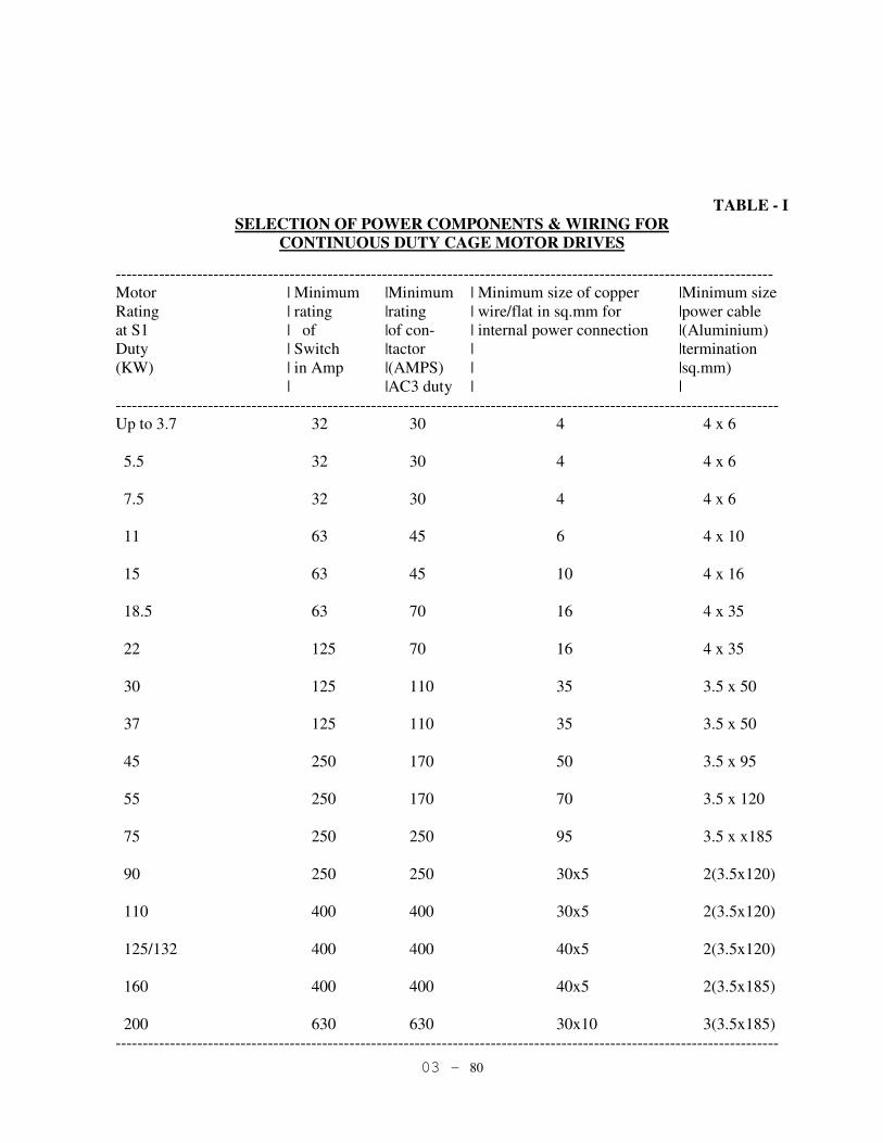
03 - 80
TABLE - I
SELECTION OF POWER COMPONENTS & WIRING FOR
CONTINUOUS DUTY CAGE MOTOR DRIVES
-------------------------------------------------------------------------------------------------------------------------
Motor | Minimum |Minimum | Minimum size of copper |Minimum size
Rating | rating |rating | wire/flat in sq.mm for |power cable
at S1 | of |of con- | internal power connection |(Aluminium)
Duty | Switch |tactor | |termination
(KW) | in Amp |(AMPS) | |sq.mm)
| |AC3 duty | |
--------------------------------------------------------------------------------------------------------------------------
Up to 3.7 32 30 4 4 x 6
5.5 32 30 4 4 x 6
7.5 32 30 4 4 x 6
11 63 45 6 4 x 10
15 63 45 10 4 x 16
18.5 63 70 16 4 x 35
22 125 70 16 4 x 35
30 125 110 35 3.5 x 50
37 125 110 35 3.5 x 50
45 250 170 50 3.5 x 95
55 250 170 70 3.5 x 120
75 250 250 95 3.5 x x185
90 250 250 30x5 2(3.5x120)
110 400 400 30x5 2(3.5x120)
125/132 400 400 40x5 2(3.5x120)
160 400 400 40x5 2(3.5x185)
200 630 630 30x10 3(3.5x185)
--------------------------------------------------------------------------------------------------------------------------
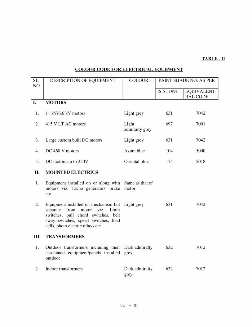
03 - 81
TABLE - II
COLOUR CODE FOR ELECTRICAL EQUIPMENT
SL.
NO.
DESCRIPTION OF EQUIPMENT COLOUR PAINT SHADE NO. AS PER
IS 5 : 1991 EQUIVALENT
RAL CODE
I. MOTORS
1. 11 kV/6.6 kV motors Light grey 631 7042
2. 415 V LT AC motors Light
admiralty grey
697 7001
3. Large custom built DC motors Light grey 631 7042
4. DC 460 V motors Azure blue 104 5000
5. DC motors up to 250V Oriental blue 174 5018
II. MOUNTED ELECTRICS
1. Equipment installed on or along with
motors viz. Tacho generators, brake
etc.
Same as that of
motor
2. Equipment installed on mechanism but
separate from motor viz. Limit
switches, pull chord switches, belt
sway switches, speed switches, load
cells, photo electric relays etc.
Light grey 631 7042
III. TRANSFORMERS
1. Outdoor transformers including their
associated equipment/panels installed
outdoor
Dark admiralty
grey
632 7012
2. Indoor transformers Dark admiralty
grey
632 7012
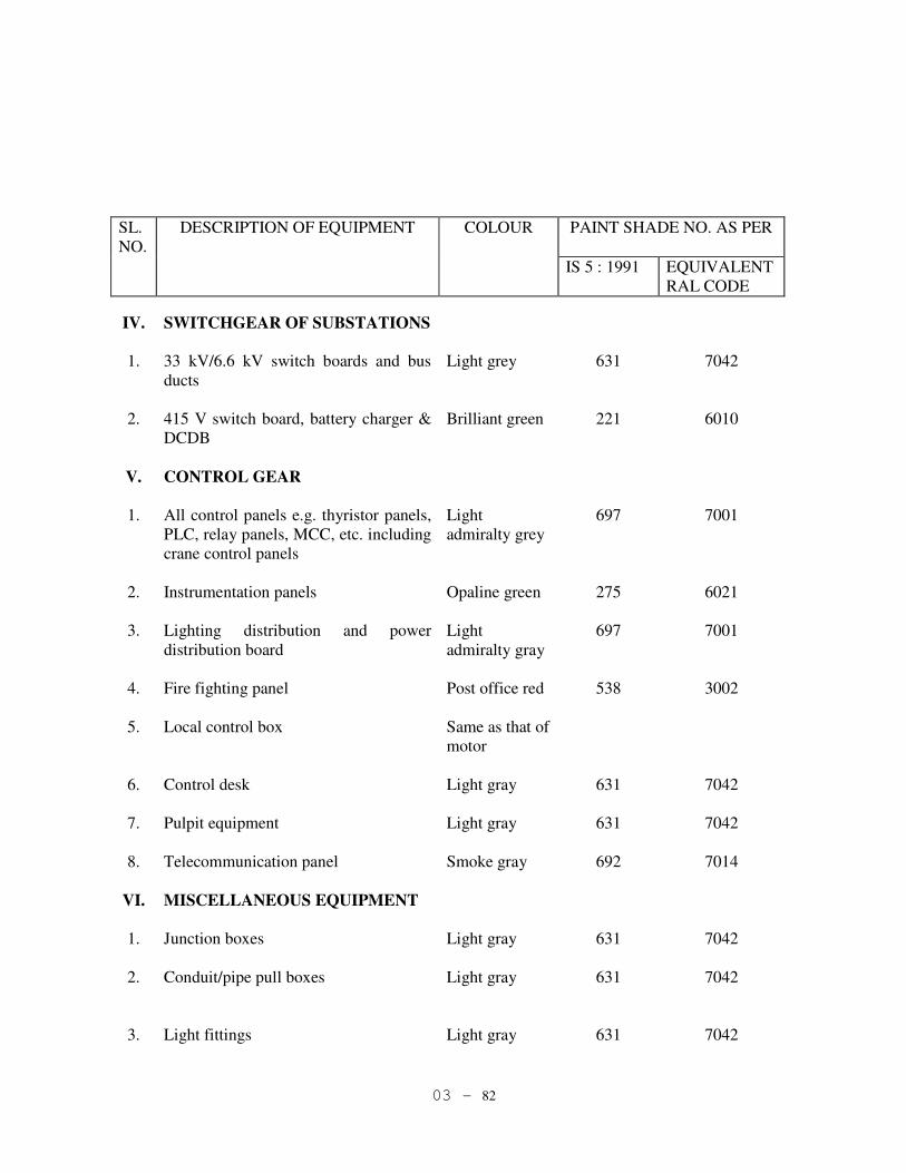
03 - 82
SL.
NO.
DESCRIPTION OF EQUIPMENT COLOUR PAINT SHADE NO. AS PER
IS 5 : 1991 EQUIVALENT
RAL CODE
IV. SWITCHGEAR OF SUBSTATIONS
1. 33 kV/6.6 kV switch boards and bus
ducts
Light grey 631 7042
2. 415 V switch board, battery charger &
DCDB
Brilliant green 221 6010
V. CONTROL GEAR
1. All control panels e.g. thyristor panels,
PLC, relay panels, MCC, etc. including
crane control panels
Light
admiralty grey
697 7001
2. Instrumentation panels Opaline green 275 6021
3. Lighting distribution and power
distribution board
Light
admiralty gray
697 7001
4. Fire fighting panel Post office red 538 3002
5. Local control box Same as that of
motor
6. Control desk Light gray 631 7042
7. Pulpit equipment Light gray 631 7042
8. Telecommunication panel Smoke gray 692 7014
VI. MISCELLANEOUS EQUIPMENT
1. Junction boxes Light gray 631 7042
2. Conduit/pipe pull boxes Light gray 631 7042
3. Light fittings Light gray 631 7042

03 - 83
SL.
NO.
DESCRIPTION OF EQUIPMENT COLOUR PAINT SHADE NO. AS PER
IS 5 : 1991 EQUIVALENT
RAL CODE
4. 415 V Welding sockets Brilliant green 221 6010
5. 230 V Power sockets Light orange 557 2000
6. 24 V transformer sockets, lamp sets
etc.
Canary yellow 309 1016
7. Earthing strip Black

04 - 1
04.01 General
Adequate and latest state-of-art technology based Instrumentation and control system
shall be provided for all the shops/units of the plant, with a view to achieve safe,
reliable, efficient and trouble-free operation of the plant as well as safety of the plant
equipment and operating personnel. The design, engineering, manufacture, assembly
and testing as well as performance of instrumentation & control equipment shall
conform to the relevant IS / IPSS / BS/ IEC/ ISA standards, unless otherwise specified
in the General Technical Specification for Tender.
All equipment supplied and all work done including system design and detailed
engineering, shall also comply with the statutory requirements of Government of India
and the State Government. ISA symbols shall be used for preparation of Process &
Instrumentation diagrams.
04.02 Environmental Specification
All instrumentation & control equipment and their accessories, including those to be
used in air-conditioned control rooms, shall be rugged, industrial grade and suitable
for use in tropical environment.
These equipments shall be suitable for operating continuously under the environmental
conditions indicated below: -
Field instruments Control room instruments
Temperature : 0 – 60°C 0 – 50°C (minimum)
Relative humidity : 0 – 95% 0 – 80 % (non-condensing).
04.03 Basic Design Considerations:
04.03.01 General
Design of instrumentation system shall take care of the following:
1. Latest state-of art and proven technology
2. High accuracy, reliable performance, modular design
3. Computer compatibility.
4. Easy testing & calibrating facilities in both local & remote mode.
5. Flexibility for maintenance work to be carried out while the process is on.
6. 4-20 mA DC signal system.
04 - 2
7. Maintenance platforms with suitable approaches for each field device.
8. Aesthetically & ergonomically designed control rooms.
9. Fail safe features.
10. Safety to the plant equipment and operating personnel.
11. Provision for future expansion in design & selection, e.g. sizing of final
control elements, flow sensors, space inside the control room, space on the
panels/cabinets/desks etc.
12. Provision for auto/remote/ manual operation for all automatic control loops.
13. Final control elements shall be with electric, pneumatic, hydraulic or hybrid
actuators depending on application requirement. Final control elements shall
have local valve position indicators and valve position transmission to control
room.
14. Steam, nitrogen, water or compressed air lines shall be provided for purging
and cleaning purposes, wherever necessary.
15. For measurement & control of critical parameters, dual redundant devices
shall be provided.
16. Uninterruptible Power Supply (UPS) system shall be considered for
automation equipment & associated field devices.
17. All pressure, differential pressure & flow transmitters shall be two- wire, true
Smart type with HART protocol operating on 4-20 mA DC principle with 24
V DC power supply and shall be able to communicate with DCS/PLC/PC &
hand held calibrator.
18. Memory of hand held calibrator shall be minimum 12 MB and shall be
supplied with precision 250 ohm resistance.
19. All recorders shall have chart speed adjustable from 20 mm/h minimum to 360
(approx) mm/h. Chart speed for fast response recorders (e.g. for molten metal
and slag temperature in steel plants) shall be of 3600 mm/h minimum.
20. All instruments shall have standard ranges. Ranges for indicators shall be
selected so that normal value shall be indicated in the middle third of the scale.
04 - 3
21. In hazardous area applications, electronic/electrical instrumentation equipment
shall be suitable for hazardous area classification as per IEC. These equipment
shall be intrinsically safe conforming to CENELEC standard and certified by
appropriate statutory bodies (FM, BASEFA etc.). Intrinsically safe systems
shall be designed using zener/ IS barriers. Where intrinsically safe design is
not feasible, ex-proof equipment/enclosure, certified by statutory bodies like
CMRI shall be supplied. Other acceptable safety procedures (e.g. increased
safety procedure, pressurisation etc.) shall be used, wherever applicable.
Required documentation/certificates shall be submitted in conformance with
all such features.
22. All transmitters shall have built-in digital output indicators calibrated in
engineering unit of flow, pressure, level, temperature, differential pressure etc.
23. Isolator cards shall be provided for isolation of instrument signals, wherever
necessary.
24. Transmitters shall be housed inside cabinets, wherever these are not installed
inside any room.
25. All field-mounted instruments shall be of suitable weatherproof construction,
as per details indicated for respective items.
26. Wetted parts of the instrumentation equipment shall be selected so as to
withstand physical and chemical properties of the service fluid coming in
direct contact with the instrument.
27. Colour codes for pipelines, cables, lamps, and panels shall be followed for the
plant as per industry/plant standard.
28. All the manufactured/fabricated items / impulse pipes & fittings shall be
properly painted as per requirement & standard practice, depending upon
nature of environment in which these are to be installed. Selection of primer
and finish paint shall be done as per relevant IS standard or equivalent
international / industry standards.
29. All fittings & accessories shall be new & rust protected. All flanged type
instruments shall be supplied with companion flanges, nuts, bolts & gaskets.
30. Instruments used on oxygen lines must be oil and grease free and shall be
marked ‘for oxygen use’ and colour coded blue.
31. Whenever corrosive atmosphere is present, all instruments and associated
equipment exposed to such a medium shall be designed & protected to
withstand the adverse effects.
04 - 4
32. Wherever instrumentation equipment is installed underground, suitable
approach, sufficient space for maintenance, drainage, ventilation and
illumination shall be provided.
33. All instrument ranges shall be standardized over the whole plant for local and
remote instruments by the expression “(1, 2, 4, 6, 8, 10, 12, 15, 50) x 10n
”,
where n = 1, 2, 3, etc.
34. Necessary certificates from appropriate authorities shall be submitted for all
applicable items.
35. Continued availability & supply of Instrumentation & control equipment
including their spares parts & consumables shall be guaranteed for a minimum
period of 10 years.
36. In case, Instrumentation & control equipment are supplied from foreign
sources / manufacturers, care shall be taken to select only those vendors who
have competent associates/ partners / representatives in India with ability to
provide required technical support & after sales service.
04.04 Temperature Measurements
1. The following types of primary sensing elements shall be used , depending on
temperature of process fluid:
a) Pt-Rh 13% / Pt ( ISA Type “R”)
b) Pt-Rh 10% / Pt ( ISA Type “S”)
c) Pt-Rh 30% / Pt-Rh 6% ( ISA Type “B”)
d) Chromel – Alumel ( ISA Type “K”)
e) Chromel – Constantan ( ISA Type “E”)
f) Copper – Constantan ( ISA Type “T”)
g) Iron – Constantan ( ISA Type “J”)
h) RTD ( Pt 100)
i) Radiation Pyrometers
2. All signals meant for control room / panel mounted instruments shall be 4-20
mADC through microprocessor based temperature transmitters. RTD shall
generally be used for measurement of -200 º C to 300 º C temperature range
& thermocouples for higher temperatures.
3. RTDs shall usually be three-wire type. Four-wire type RTDs shall be used,
whenever specifically required by purchaser / consultant.

04 - 5
4. Temperature transmitters or secondary instruments used with thermocouples
shall have automatic cold junction compensation. All temperature transmitters
shall be SMART type HART protocol. Enclosure class of temperature
transmitter shall be IP 67.
5. Resistance thermometers (RTD) shall be used for cryogenics and low
temperature in general.
6. Thermocouples shall normally be mineral insulated (i.e., extruded MgO) type.
However, for applications exceeding 1100°C, lead type ceramic insulation
shall be provided. Ceramic insulation shall be of recrystallised alumina
(Al2O3-99.7%) as per DIN VDE 0335.
7. Thermocouple assembly shall be spring-loaded to ensure positive contact with
thermowell.
8. Measuring junction of thermocouples shall be grounded or insulated
depending on the type of electric system or safety protection requirement.
9. Separate conduits or cable entries shall be provided where duplex
thermocouples are used.
10. Thermocouple calibration shall be in accordance with IS, DIN, IPTS or
equivalent standard:
11. For Pt-Rh / Pt thermocouples, Linearisation shall be done in secondary
instruments, DCS/PLC or using separate Linearisation card in temperature
transmitter.
12. Thermowells fabricated out of bar stock having sufficient mechanical strength
shall be provided to enable maintenance work of thermocouple / RTD without
affecting production.
13. AISI 316 shall be used as thermowell material, unless other special material is
required due to process fluid and conditions. For temperature range between
800°C – 1100°C, Inconel 600 shall be used as thermowell material. For
temperature more than 1100°C, ceramic thermowell shall be used. Ceramic
material shall be selected based on the process environment.
14. Any pipe of less than 4” nominal diameter, shall be expanded to 4” size to
install thermowell.
15. Thermocouples shall be complete with compensating leads, installation
fittings. The indicators, controllers shall have broken sensor protection.

04 - 6
16. Interconnections to / from thermocouples to temperature transmitter shall be
made via compensating cables of thermoelectric characteristics matched with
thermocouple.
17. Bimetallic type thermometers having minimum dial size Φ150mm shall be
used for local indication of temperature. Temperature gauges with smaller
dial sizes may be used for machine mounted applications.
18. For bimetal type thermometers, external dial reset facility shall be provided for
zero adjustment.
19. Capillary tubes, wherever used, shall be of stainless steel material with flame-
proof PVC, neoprene or steel armour, as suitable for the application.
20. In case, compensating leads are to be laid on the top of the furnace /hot
surface, these shall be asbestos covered with mesh shielding or other suitable
insulating materials. Mineral insulated cables shall also be used for such
applications.
21. Compensating cables connected to transmitters shall not be through terminal
blocks but shall be directly connected.
22. A protection tube consisting of a gas-tight ceramic sheath, preferably
reinforced with stainless steel, shall be provided with Pt-Rh/Pt thermocouples,
unless some other special construction is specified.
23. Radiation pyrometers shall be used when:
a) Measured temperature is beyond the practical operating range of
thermocouples.
b) Environment will contaminate or seriously limit the life of the
thermocouples.
c) Target is not easily accessible.
d) Average temperature of a large area is to be measured.
24. Normally, the radiation pyrometer shall respond to 98% of the target
temperature.
25. Radiation pyrometers shall be provided with scavenging air or nitrogen to
keep their lens clean and shall be water-cooled or air-jacketed when the
surrounding temperature exceeds 50°C.

04 - 7
26. Isolation valve shall be provided before radiation pyrometer for on-line
maintenance of radiation pyrometer.
04.04.01 Molten Steel Temperature Measurement System
1. For molten steel temperature measurement, disposable type immersion
thermocouples having response time of less than 3 seconds shall be used. The
corresponding temperature measurement system shall be complete with lance
assembly, adapter, disposable thermocouple cartridge and two-way connector
for the lance.
2. For immersion type hot metal / steel temperature measurement, shielded flame
proof and heat resistant compensating cables shall be provided.
3. Temperature measurement system shall be microprocessor based.
4. Linearisation required for R & S type thermocouple shall be done in
microprocessor based temperature measurement system.
5. 4 – 20 mA analog output for the measured temperature shall be provided for
hooking up to DCS/ PLC.
6. 4 ½ digit type digital indication shall be provided in the temperature
measurement system panel. This digital indicator shall retain the last value
until the next measurement cycle is initiated by inserting the thermocouple
probe in the lance.
7. One printer shall be provided in the temperature measurement panel for
printing the measured temperature along with the heat no. Heat no. will be
down loaded to the measurement system from DCS/ PLC through RS 232C/
RS 422/ RS 485 link.
8. Ready, measurement and measurement complete/ probe open signals shall be
displayed in the measurement system panel with green, yellow and red LED
indication.
9. In the field, one local control box, 200 mm jumbo display for temperature
indication and red, yellow and green lights for measurement complete/ probe
open signal, measurement and ready status display shall be provided.
Measurement complete/ probe open shall also be indicated by blowing horn.
10. Power isolation switch at local control box end shall be provided.

04 - 8
11. 24 V DC signals and 230 V AC signals shall be segregated in the local control
box and microprocessor based temperature measurement system panel.
04.05 Flow Measurement
04.05.01 For Fluids:
1. Normally orifice plates, magnetic flow meters or vortex flow meters shall be
used for flow measurement of industrial service fluids, depending on the merit
of the application.
Positive displacement, turbine and Coriolis flow meters shall be used in
custody transfer measurements and in processes, where high measurement
accuracy is required.
However, other types of flow meters may also be used when necessitated by
particular technical requirements.
2. Vortex flow meters shall be generally be used for steam/gas service, upto 8”
line size.
3. Magnetic flow meters shall be used for fluids having conductivity greater than
5 µS/cm.
04.05.01 Differential Pressure Type Devices
1. Normally, concentric square-edge type orifice plates shall be used.
2. For better accuracy, the Beta (β) ratio of concentric type orifice plates shall
not preferably exceed 0.6. However, in no case, β shall exceed 0.7.
3. Concentric square-edge plate thickness shall be determined as follows: -
2 to 12” (i.e., 50 to
300 mm)
3.18 mm
14” and above 6.35 mm
For temperature
>316°C
2 to 8” (50 to 200
mm)
3.18 mm
10” & above 6.35 mm
4. Quarter-circle and conical entrance type orifice plates shall be used with
viscous fluids.
5. Eccentric or segmental type orifice plates shall be used with dirty fluids.

04 - 9
6. Flow nozzle, venturi or averaging pitot tube may be used in high flow
applications or where the allowable pressure-drop is low.
7. All orifice plates shall normally be made of AISI 316 material, unless
otherwise called for by process requirement.
8. For line size below 2”, carrier-ring type orifice plate with corner tapping shall
be used.
9. For line sizes greater than 2”, orifice plate with flange tapping shall be used.
10. Corner or D & D/2 type tappings shall be used only when flange tapping is not
viable due to pressure loss or other considerations.
11. All orifice plates shall be fabricated with a collar, which shall extend outside
the mounting flange.
12. Tag no., orifice plate bore diameter, upstream (+) and downstream (-) side
marking, and plate material shall be engraved on the handle of the orifice
plate.
13. Flanges shall be in accordance with ANSI B16.36 and of minimum Class 300
rating upto line size of 24”. For line sizes above 24”, flanges in accordance
with IS 6392, and of suitable rating shall be used.
14. Tag no., flange size, flange rating and flange material shall be engraved on all
flanges.
15. Gasket material for orifice plates shall be suitable to withstand physical and
chemical properties of process fluid and shall be matched with the pipeline
standard, as required.
16. Supply of orifice plate assembly shall include the orifice plate, flanges, stud-
bolts, nuts, jackscrews, gaskets, pressure tapping nozzles and plugs.
17. Drain / vent hole correction shall be as per ISA RP 3.2.
18. Orifice plate or flow nozzle shall be installed as per standard, but not less than
with straight pipe lengths of 10 times pipe internal dia. (10 D) on the up
stream and 5 D on the downstream, free from bends, tees, branch pipes and
control valves, etc. Upstream and downstream straight pipe lengths shall be as
per section 1.1 of BS 1042. 1981.
19. Control valves shall be installed after the orifice plates in the direction of flow.

04 - 10
20. All flow meters shall have drainage valves except in oxygen and nitrogen
service.
21. Corrosive media shall be separated from transmitters by separating chambers
with valves for isolation
22. For steam flow and flow of liquid at temperature greater than 120°C
condensation chambers of identical dimensions shall be used. Condensation
chambers shall be installed as near to flow sensor as possible.
23. Depending on specific requirements/applications, averaging pitot tubes with
multiholes (eg, Annubar type) placed in the direction of fluid stream may also
be used. The calculations and design shall be as per manufacturer’s standard.
24. For DP based flow measurement in pipe line sizes of ½” to 1-1/2”, integral
orifice type flow meters shall be used.
25. IBR certification shall be provided for steam and vapour applications, as per
IBR standard.
26 All flow meters on inter plant pipes for gas balance system shall have an
accuracy of 0.5% f.s.d. or better.
27. In contaminated water lines / gas / orifice plates shall be installed in bypass
line with isolation valves. So that on-line maintenance shall be possible.
28. Generally, metal tube type rotameters shall be used. Glass-tube enclosed type
rotameters may be used up to 3 kg/cm2 process pressure, if the process fluid is
air, inert gas or water.
29. For line size greater than 2”, bypass type rotameters shall be used, instead of
on-line mounted type.
04.05.02 For solids:
1. Generally, flow measurement of solids in powdered, amorphous or granular
form shall be done using ultrasonic type or load-cell based weigh-hopper type
or nucleonic type sensors, depending on the merit of the application.
2. For measurement of mass flow of suspended solids in liquids or slurries,
nucleonic type instruments shall be used.

04 - 11
04.05.03 Vortex Flowmeters:
For selection of vortex flow meters, following to be taken into account: -
1. Reynold’s no. shall be at least 20000 and minimum flow velocity shall be as
specified by manufacturer.
2. Vortex flow meters shall not be considered in wet gas application.
3. Vortex flow meters shall not be considered for viscous, waxy or erosive
services.
4. For gas application, the bluff body shall be in horizontal position to avoid
condensate and for liquids in vertical lines the flow shall be upwards to keep
the line full.
5. A location with minimum pipe vibration shall be selected. The pipe shall be
supported at both ends, as necessary.
6. If pressure and temperature compensation are required for gas flow
application, the pressure tapping shall be placed as close as possible to
upstream of flow meter. The temperature tapping point shall be located at least
5D on the downstream of flow meter.
7. Straight length requirement shall be as specified by manufacturer. If meter size
is smaller than the line size, concentric pipe reducers shall be used. Eccentric
reducers shall not be used as they disturb the flow profile.
8. All vortex flowmeter shall be SMART type with HART protocol. Local
display of vortex flowmeters shall be calibrated in engineering unit.
9. Accuracy of the vortex flowmeter shall be ± 1% or better.
10. Sensing technique of the vortex flowmeter shall not be thermistor based.
11. Necessary calibration unit for checking the electronic unit of vortex flowmeter
shall be provided.
12. Enclosure class of vortex flowmeter shall be IP 67.
04.05.04 Electromagnetic Flow Meters:
1. Selection of Electromagnetic flow meters, shall be decided based on the
following: -
a) Liner material shall be selected based on service. Generally, for liner
material PTFE shall be used.
b) If gases are entrained in the liquid, meter shall be installed in vertical
process line.
c) While installation it shall be ensured that flow tube is always completely
filled with liquid.
d) Straight length requirement of minimum 5 D in the upstream and 3 D in
the downstream shall be provided for water services. However, for other
services it shall be designed as per manufacturer’s recommendation.
e) Installation of electromagnetic flow meters shall be avoided near large
conducting surface e.g. metal surfaces. (Large surface may interfere with
magnetic field of instrument thus affecting accuracy).
04 - 12
f) Pulsed DC excitation shall be provided for field excitation of Electro
magnetic flowmeter. Power & signal circuits of magnetic flowmeter shall
be completely isolated from each other.
g) Minimum one no. of grounding ring for metallic pipelines and minimum
two nos. of grounding rings for non-metallic pipelines shall be used for
installing the magnetic flow meter.
h) Selection and sizing of electro-magnetic flow meters flow characteristics
published by the manufacturers shall be followed. Allowable flow
velocity shall be considered based on the specific merit of the service,
allowable pressure drop, cost effectiveness and as per manufacturers
recommendation. However, 2 to 3 meter/ sec flow velocity shall be
considered for optimum results.
i) In case tube sizes are lower than the process pipelines reducers and
expanders constructed preferably from the same as pipeline material shall
be used. Such reducers and expanders shall be designed with 8(eight)
degree downward and 5(five) degree upward angle respectively.
j) All magnetic flowmeter shall be SMART type with HART protocol.
Accuracy of magnetic flowmeter shall be ± 0.3% or better. Local display
shall be calibrated in engineering unit.
k) In contaminated water lines, magnetic flowmeter shall be installed in
bypass line with Isolation valve.
l) Sensor & transmitter of the magnetic flowmeters shall separated in all
cases.
m) Magnetic flowmeter shall be provided with built-in auto zero facility for
ensuring stable zero point.
n) Separate earthpit shall be provided exclusively for earthing of magnetic
flowmeters. Preparation of such earthpits shall be governed by the general
methodology as described in IS 3043, 1991 or relevant international
standards.
o) Necessary calibration unit for checking the electronic unit of magnetic
flowmeter shall be provided.
p) Enclosure class of magnetic flowmeters shall be IP 67.
04.05.05 Coriolis Mass Flow Meters:
1. For selection and sizing of coriolis type flow meters, following shall be taken
into account: -
a) If required flow rate cannot be handled by one meter, two or more meters
can be used in parallel.
b) Selection of wetted part materials shall be carefully chosen to suit process
fluid.
c) SS shall not be used for liquids containing Halogen. Hastelloy tubes shall
be used for all application containing Halogen.
d) Coriolis mass flow meters shall not be used in two-phase fluid application.

04 - 13
e) Pressure drop across flow meter shall be selected, ensuring no cavitation
occur under any process condition.
f) Flow meter support shall be as per manufacturer’s recommendation.
04.05.06 Ultrasonic Flow Meters:
1. For selection of Ultrasonic flow meters, following to be taken into account:
a) Ultrasonic flow meters shall be used in clean liquids and gases.
b) Ultrasonic flow meters shall be used where pressure drop is not allowed.
c) On critical services Ultrasonic flow meters with insertion probes shall
have retraction mechanisms to allow on stream maintenance.
d) Clamp on type shall only be used for liquid metering.
04.05.07 Turbine flow meters.
1. Turbine meters for custody transfer shall have two pick-up coils for use with
an electronic pulse integrity input circuit in read out system.
2. Turbine type meters shall have flanged connections
3. Strainers shall be provided immediately upstream of turbine meters
4. In liquid service, adequate filtering and degassing shall be provided.
04.05.08 PD Meters:
1. Positive displacement type meters shall have flanged connections.
2. PD meters shall not be selected for use in non-lubricating liquids e.g. LPG.
3. Strainers shall be provided immediately upstream of PD meters.
4. In liquid service, adequate filtering and degassing shall be provided.
04.06 Pressure Measurement:
1. Either bourdon tube (spiral or helical), bellows or diaphragm type sensing
element shall be used in pressure gauges/ switches, depending on the process
service.
2. The pressure gauges shall be designed in accordance with IS 3624.
3. Pressure gauge accuracy shall be ±1.0% of span or better. Accuracy shall
include the combined effect of linearity, hysterisis and repeatability.
4. The element and other wetted part materials of pressure gauges/ switches shall
be of AISI 316, unless process media necessitates use of other materials.
5. Movement material of gauges shall be of AISI 304. Outer casing and bezel
material shall be either made of die cast aluminium with epoxy coating.

04 - 14
6. Pressure gauges shall have external zero adjustment facility and minimum
IP55 housing.
7. The sensing element of pressure gauges/ switches shall withstand the specified
over-pressure (i.e., at least 125% of span) for at least 30 minutes, without
affecting their elastic characteristics.
8. Pressure gauges shall have dial size of 150 mm diameter. Gauges of smaller
dial size may be used for machine mounted applications.
9. Pressure gauges/ switches used in pulsating pressure applications (e.g.
delivery side of pumps, compressors, etc.) shall be provided with externally
adjustable pulsation dampener or snubber.
10. Wherever the process temperature exceeds 70°C, pressure gauges/ switches
shall be equipped with pigtail syphon of the same material and schedule as the
process pipeline.
11. Wherever the process pressure exceeds 50 kg/cm2, solid front type pressure
gauges shall be used (i.e., a metal partition shall be provided between dial and
element).
12. Window material of the pressure gauge shall be of shatterproof glass.
13. For pressure measurement in slurries, viscous and corrosive fluids, diaphragm
seals of suitable material shall be provided alongwith pressure sensing
devices. Diaphragm seals shall be integral with the gauges /switches, unless
otherwise specified.
14. The sealing liquid for diaphragm seal shall be an inert liquid compatible with
process fluid and its temperature.
15. Depending on process application, suitable chemical seal along with capillary
of required length shall be provided
16. Diaphragm seal type pressure gauges / switches used in applications where the
temperature exceeds 100°C, shall have bourdon / bellows type element. The
bourdon / bellows shall be selected to withstand temperature upto 200°C.
17. However, in vacuum service, if the temperature exceeds 200°C, diaphragm
seal shall not be used.
18. The working range of pressure switches shall be selected in such a way that
the set pressure is between 35% and 65% of the range.

04 - 15
19. The switch enclosure shall be weatherproof to IP 65. Additionally, in
hazardous areas, switch enclosure shall be explosion-proof conforming to IS
2148 and suiting to the area-classification of the hazardous area.
20. Dry contact type micro switches with minimum rating of 240VAC,5A /
110VDC, 0.4A shall be used for pressure switches in non-hazardous area
applications.
21. In hazardous areas, hermetically sealed micro switches with minimum rating
of 240 VAC, 5A / 110VDC, 0.25A shall be used.
22. Pressure switches shall have an accuracy of at least ±2% of span and
repeatability of at least ± 1% of span.
23. Accuracy of DP gauges shall be ± 1.5% of span. Accuracy shall include the
combined effect of linearity, hysterisis and repeatability.
24. Pressure gauges shall be supplied with three-way gauge cock. DP gauges shall
be supplied with 3-valve manifolds of AISI 316 material of suitable pressure
and temperature rating. The above items shall be in addition to the process
isolation valves/ root valves at the process tapping point.
04.07 Transmitters
1. Pressure, flow, differential pressure and level transmitters shall be rugged,
industrial, microprocessor based ‘Smart’ type. Transmitters shall work on 24
V DC power supply having 2-wire, 4-20 mA DC output & ‘HART’ protocol
based digital communication.
2. Accuracy of all transmitters shall typically be 0.1% or better, of calibrated
span for turn-down ratio of minimum 10:1 and rangeability of 100:1.
Accuracy shall include the combined effects of linearity, hysterisis and
repeatability. In any application, the worst case error (WCE) consisting of
static pressure effect, temperature effect, humidity effect and stability (1 year)
shall not be greater than 0.75%, unless specified otherwise. Zero and span
adjustments shall be non-interacting to each other.
3. Total response time (including dead time and time constant) of the transmitters
shall be less than 100 ms.
4. Transmitters shall be suitably compensated against any thermal effects in the
process medium.
04 - 16
5. Transmitters shall be able to withstand a minimum over pressure of 150 % of
the rated pressure.
6. All the transmitters shall be weather-proof to IP-67.
7. Zero suppression & elevation features, built in surge protection and provision
for selection of different damping levels shall be provided in each transmitter.
Absolute pressure transmitters shall have provision for compensation of
barometric pressure.
8. All transmitters shall have integral local linear digital indicators calibrated in
engineering unit. DP transmitters for flow applications shall have built-in
square root extractors. Local indications shall be adjusted / calibrated through
hand held calibrator.
9. Power supply effect on transmitters shall be less than ± 0.05 % of calibrated
span/10 V.
10. Pressure transmitters shall be supplied with 2- valve manifolds of AISI 316
material. Flow; DP and level transmitters shall be supplied with 3-valve
manifolds of AISI 316 material having suitable pressure and temperature
rating. Standard zero suppression / elevation facilities and output reversal
facility shall be available for all transmitters. All the required accessories for
mounting shall also be supplied with the transmitters.
11. One hand-held calibrator with required software, rechargeable battery and
battery-charger shall be supplied for calibration checks of the transmitters.
04.08 Level Measurement
04.08.01 General
Selection of primary elements shall be based on the service conditions. A general
guideline is given below. However, selection of particular type of sensor shall be
decided on the basis of application requirement.
1. For Liquid Service
i) Pressure / differential pressure type level transmitter with/without
diaphragm seals
ii) Float or Displacer type level transmitters
iii) Ultrasonic type
iv) Radar type
v) Vibrating fork type
vi) Gauge glasses

04 - 17
vii) Magnetic level gauges
viii) Capacitance type
ix) Conductivity type
x) RF Type
xi) Time domain reflectometry type
2. For Solid Service
i) Ultrasonic
ii) Nucleonic
iii) Load Cell (weighing) system
iv) Electromechanical servo gauges
v) Tilt switches
vi) Capacitance switches
vii) Vibration rod
viii) RF Type
ix) Time domain reflectometry type
3. For sumps
i) Conductivity switches
ii) Capacitance switches
iii) Bubbler Tube System
4. Tank gauging
i) Servo gauges
ii) Radar
5. Level instruments shall have weatherproof, dust and corrosion resistant
enclosures of minimum IP-65 grade.
6. Additionally, explosion-proof enclosures shall be provided for hazardous area
applications.
7. In Tank Gauging applications, communication port shall be provided in level
instruments, for connectivity to a computer.
04.08.02 Gauge Glasses
1. All gauge glasses shall normally be steel armoured reflex or transparent type.
Magnetic level gauges may also be used when liquid temperature permits and
liquid specific gravity is greater than 0.9.
2. Reflex gauges shall be used on clean, clear, non-corrosive liquids.
3. Transparent gauges shall be used for the following applications:
04 - 18
i) Interface service
ii) When the process is dirty or viscous
iii) For corrosive medium, (such as caustic, hydrofluoric acid and steam
applications above 250 PSIG), transparent gauge glasses shall be used
with internal mica or plastic shield to prevent chemical attack or
discoloration of the glass.
4. If the process is a solvent that can dissolve the internal coating of the chamber
of the reflex gauge, thereby reducing the effectiveness of the prisms, reflex
gauges shall not be used.
5. Reflex gauge glasses shall not be shielded
6. Transparent level gauges, in general, shall be equipped with minimum 40 W
illumination and switch (ex-proof for hazardous area).
7. For high temperature applications, level gauges with flexible end tube
coupling or expansion loops (top/bottom) shall be used to take care of high
temperature expansion.
8. Large chamber type gauge glasses shall be used for boiling / evaporating and
heavy viscous liquids.
9. Gauge glass material shall be toughened borosilicate glass having adequate
resistance to thermal and mechanical shock.
10. Gauge glass body and cover shall be made of carbon steel with rustproof
finish, unless otherwise specified.
11. Gauges shall be provided with safety ball check offset type gauge cocks, vent
and drain connection (with 1/2” vent & drain valves), nipples, caps etc.
12. Gauge glasses shall be provided with top and bottom or side connections.
Where side connections are specified, the gauge glasses shall have two
connections at each end, 180° apart, with one connection at each end plugged.
13. Unless otherwise specified, gauge cocks shall be of the quick-closing type
with bolted bonnet, outside screw and renewable seats.
04.08.03 Displacer Type & DP Type
1. External displacer type instruments with rotable head shall usually be used for
level measurement upto 1200 mm (48”), wherever process permits.
04 - 19
2. Displacers shall be made of AISI 316 with Inconel torque tube, unless
otherwise specified or unless the process calls for any special material.
3. Side-side flange connection shall normally be used. Heat insulator / finned
extension shall be used for temperatures above 230°C.
4. All such instruments shall have drain valves and vent plugs.
5. Stilling wells shall be provided for internal displacer type level instruments.
6. Differential pressure transmitter shall be used for level measurement in boiler
drums and in other cases, where displacer type instruments are not suitable
(e.g. level measurement beyond 1200 mm, applications requiring purge or
where liquid might boil in external portion).
04.08.04 Vibration Fork
Vibration fork type level switches shall generally be used instead of float type level
switches. Further, external cage type construction shall generally be used. Process
connection to the cage shall be 1“ socket weld type, unless otherwise specified.
04.08.05 Ultrasonic
1. Ultrasonic type level transmitters shall be microprocessor based and shall use
digital signal processing technique for signal conditioning. Possible to
calibrate through universal HART calibrator.
2. Suitable protection box for mounting ultrasonic type level transmitters shall be
provided for mechanical protection & dust. Swiveling arrangement shall be
provided for proper aiming/ focusing of ultrasonic type level transmitters.
3. The transmitter shall have facilities for storing the echo profile, manipulation
of the echo profile to remove noise, multiple profile-averaging etc.
4. The transmitter shall have the capability to use statistical filtering techniques,
wherever required, to compensate for rotating agitator blades or to suppress
false signal due to heavy dust or fill-stream interference.
5. In very dusty applications or in silo / bunker, etc. filling applications, high
power and long range (i.e., low frequency) transducer shall be used to
overcome the detrimental effect of the dust. This type of instrument shall not
be used for level measurement in process medium consisting of particles of
sizes (- 6 mm diameter).

04 - 20
6. The sensor shall have inbuilt temperature sensor for ambient temperature
compensation.
7. Chemical compatibility of the sensor material with the process material shall
be ensured, to avoid corrosion.
8. In applications, where material build-up on the sensor is expected, the
transducer shall have suitable build-up compensation (i.e. repetitive, pulsating
displacement at its face shall be used to remove the material build-up).
9. Ultrasonic transmitters shall be supplied along with necessary calibration &
noise suppression software, HART to RS 232C modem, plug connector, cable,
etc. for connection to a desktop PC/ Laptop.
04.08.06 Nucleonic Type
1. Nucleonic sources shall have adequate shielding to limit radiation level at any
point on the surface to below 6 milli-Roentgen per hour. At the same time,
nucleonic type measurement systems shall not be excessively bulky or heavy.
2. Nucleonic sources shall have facilities for complete shielding during shipping,
storage and transportation (in the form of rotary shutter, etc.).
3. The supplier shall furnish necessary certification of nucleonic type instruments
from statutory bodies, as applicable.
04.08.07 Capacitance & Conductivity Type
1. Capacitance / conductivity type probes shall be as follows:
i) Rod type : for length upto 2000mm.
ii) Rope type with gravity weight : for length exceeding 2000 mm.
2. For level measurement in non-conducting tanks or sumps or when the tank
profile is non-linear, capacitance type instruments shall be provided with a
reference electrode / ground probe.
3. Capacitance type level probes may be used for both switching as well as for
continuous level measurement in liquids.
4. Capacitance type level probe shall not be used for level measurement in solids
when there is likelihood of material build-up on the probe. Capacitance type
level probe shall not be used in liquid service where there is a chance of di-
electric value change (due to oil spillage etc.).
04 - 21
04.08.08 Radar Type
1. Radar type level instrument shall be used when the physical properties of the
medium between the sensor and the measured interface may vary.
2. The Radar type level instrument shall be microprocessor based and shall use
digital signal processing techniques for signal conditioning. Possible to
calibrate through universal HART calibrator.
3. Level instruments mounted in fixed roof type tanks shall have no stilling
wells.
4. Suitable antennae shall be considered by supplier.
5. Wetted part materials of the sensor shall be chemically compatible with the
process media to avoid corrosion.
6. Necessary software, cables, connectors, HART to 232C converters etc. For
calibration, noise suppression, etc. of Radar type level transmitters through
windows based desktop PC / Laptop shall be supplied.
7. Suitable protection box for mounting radar type level transmitters shall be
provided for mechanical protection & dust. Swiveling arrangement shall be
provided for proper aiming / focussing of radar type level transmitters.
04.08.09 Time Domain Reflectometry Type (TDR)
1. TDR type level measuring system shall be mainly used.
i) For level measurement of Liquids, interface in immiscible fluids,
granules & fine powders
ii) For medium having dielectric within 1.8 to 100.
2. Co-axial type, twin rods, twin cables, single cable / rod type probes shall be
selected depending on tank height, properties of medium/media & application.
3. For interface level measurement top layer shall be of lower dielectric and
minimum difference of dielectric between top & bottom layer shall be as per
manufacturer’s recommendation
4. For adhesive/sticky in nature materials, coated probes as per manufacturer’s
recommendation shall be used.
04 - 22
04.08.10 Radio Frequency (RF) Type
1. Radio frequency (RF) continuous/ point level measuring system, based on
capacitance or admittance shall be used for level measurement of liquids,
slurries, granulars, and liquid-liquid interface.
2. RF transmitter shall be
i) Smart type
ii) Self-calibrating type i.e. as the level rises in the vessel, the span is set
automatically and electronically by the smart transmitter.
3. For high temperature application, remote mounted transmitters shall be used.
4. RF type shall also be used for detection of absence or presence of liquids,
slurries, interfaces and granulars.
5. One hand-held calibrator with rechargeable battery and battery-charger shall
be supplied.
6. It shall be possible to calibrate RF transmitters using calculated or known
levels of capacitance directly entered by the hand held calibrator.
04.08.11 Others
Tilt Type, paddle type, bubbler type, electromechanical type, etc. level instruments
may also be used, depending on application specific requirement.
04.09 Gas Analysis System
1. The gas analysis system shall be complete with the following units:
i) Gas sampling probe, complete with filters, isolation valves, ring
heaters, insulator jackets etc, as required. Dual probes shall be used,
wherever required as per process criticality.
ii) Gas preparation & conditioning system including sample conditioning,
pumping, cooling, cleaning, drying etc. as applicable along with filter
panels, scavenging panels complete with valves, tubing, fittings,
accessories etc, as required.
iii) Gas analyzer panel with analyzer instruments, monitoring devices viz,
flow, pressure, temperature etc, tubing, fittings, accessories, as
required.

04 - 23
iv) UPS & non-UPS type electrical power supply for the complete gas
analysis system, complete with isolation transformer, Circuit breakers,
MCBs, relays, 24 V DC regulated power supply units, earthing system
etc, as required for efficient performance of the analyzer system.
v) Calibration equipment with calibration gas cylinders. Facility for both
automatic & manual mode of calibration shall be provided. Cross
sensitivity correction shall be provided wherever applicable.
2. Suitable display unit with key-board/ switches shall be provided on the
analyzer panel front for monitoring & display of different parameters, status of
analyser & sample conditioning equipment etc.
3. Condensation monitors, complete sampling system shall be designed &
supplied by the analyser manufacturers only. All components & fittings of the
analyser & sample conditioning system shall be of reputed make, preferably
imported.
4. Before the filter unit, SS isolation valves shall be provided for each probe to
facilitate online changing of the filter unit. Sample gas coolers shall be
provided with redundant sample gas path & peristaltic pumps.
5. Sampling of dusty, hot, dry, cold or wet gases shall be done using dual probes
with automatic switchover and with intermittent purging facility.
6. Analyser shall be microprocessor-based and the analyser PLC shall do all
related sequencing & logic functions. Analyser PLC shall preferably have the
same series & model no. as envisaged for the main unit / plant to ensure
reliable & trouble-free communication.
7. System & application software for configuring and diagnostics of the analyser
PLC shall be provided.
8. Response time of the Analyser system shall be designed to comply with
process requirements.
9. Unless otherwise specified, accuracy of analyzers shall be within ±1% of span.
Repeatability of analyzers shall be within ± 1%.
10. Where there is a possibility of choking of analyser inlet filters, automatic inert
gas purging facility initiated by the analyser PLC shall be provided.
11. All solenoid valves used in gas analysis system shall have manual override.

04 - 24
12. Separate analyser room shall be provided in the vicinity of gas sampling
points. However, storage of calibration gas cylinders shall be arranged outside
the analyser room. Room CO monitoring unit shall be provided in the analyser
rooms.
13. Analyzers in explosion hazardous area shall be installed in ex-proof shelters.
14. Exhaust tubing shall be provided for the sample gas after analysis and will be
either vented into atmosphere at safe elevation/ distance, or fed back into the
process stream. Gases containing hydrogen shall have separate outlets.
15. Analysis system of Hydrogen & other explosive gases shall bear the approval
of statutory body.
16 Wherever analysis of harmful gases has to be done, unmanned gas analyser
room with proper air conditioning` facility shall be planned. At least one inert
gas and / or steam purging point with flexible hose connection and isolation
valve shall be provided at the entry point of this room.
17. In analysis of explosive gases (or gases forming an explosive mixture),
approval of design and installation of analyser system shall be obtained from
competent authority.
18. Poisonous and explosive gas detection systems shall have safety-limit alarm
annunciation. Safety limits of different gases shall be as per OSHA norms.
19. Normally, the following types of gas detectors / sensors shall be used.
However, type of sensor shall be selected, depending on the application:
i) Electro-chemical cell
ii) Semiconductor/ solid state cells
iii) Thermal conductivity
iv) Paramagnetic
v) Catalytic
vi) Non-dispersive Infra-red radiation type
20 Liquid Analysis System:
i) Analysis of pH or Oxidation–Reduction Potential (ORP) of industrial
liquids shall be done using a measuring electrode and reference calomel
electrode sensing system. The type of electrodes shall be selected based
on the electrochemical and physical properties of the liquid.
04 - 25
ii) Material of construction of conductivity analysis cell shall be based on
the chemical corrosion activity and physical properties of the process
medium. The type of electrodes shall be selected based on the
electrochemical and physical properties of the liquid.
iii) Buffer solution shall be provided along with the analyser for calibration
purpose.
04.10 Control Valves
1. Control valves shall be provided with by-pass valves, except where the valves
are used in split-range service.
2. Control valve characteristics shall be chosen in accordance with process
requirement.
3. Control valves shall be sized in accordance with ISA-S75-01.
4. Valve sizing software, wherever used, shall be submitted alongwith sizing
calculation.
5. Control valves shall be sized so that at minimum and maximum flow, the
valve lift is always between 10% to 90% for equal% and 20% to 80% for
linear characteristics..
6. All control valves shall be provided with hand wheel.
7. Wherever required (such as, in high temperature applications) or wherever
specified, hard-faced or stellitied valve trims shall be provided.
8. In extreme temperature applications, seal-welding of threaded seat-rings, etc.
shall be done.
9. In very low temperature applications, valve trim materials shall be chosen to
have adequate cold impact strength.
10. ‘Trim’ of a control valve shall include those parts of body assembly
(excluding body, bonnet and bottom flange), which are exposed to and in
contact with, the process medium. These parts shall consist of but not be
limited to the seat ring, valve plug, plug stem, plug guide bushing and cage.
11. Valve guide bushing shall be of sufficiently hard material to resist side-thrust
on the valve plug.
12. For temperature applications below 200°C, ‘Teflon’ valve packing shall be
used.

04 - 26
13. For temperature applications exceeding 200°C, ‘grafoil’ packing shall be used.
14. Steam / electrical tracing shall be provided to control valves, wherever process
demands.
15. Control valves in steam service shall be provided with IBR certification.
16. Valve body size shall be minimum 25mm. However, reduced trim may be
provided with 25mm valve body, if the process demands.
17. Globe type control valves shall be in general be used in throttling applications.
i) Valves of 1” to 4” size shall be single-seated type.
ii) Valves above 6” size shall be single-seated cage type.
18. Extension-bonnets shall be provided in control valves for services above
200°C or below (-) 30°C, or as recommended by the manufacturer.
19. Other types of valves (e.g. butterfly, eccentric-disk, ball, V-notch ball type,
etc.) shall be used only when operating conditions do not allow globe type
valves.
20. For high viscous liquids, V-notch ball valves shall be used.
21. Single-seated globe and angle type valves shall have heavy top guiding.
22. Double-seated valves, wherever used, shall be cage-guided type with pressure
balance.
23. Large size piston-operated and diaphragm-actuated type control valves or
dampers shall be provided with positioners. Such valves or dampers shall have
signal bypass facilities for manual local operation.
24. Butterfly type control valves shall be designed for maximum opening angle of
60°C. The maximum permissible opening for eccentric disk type control
valves shall be 90°C.
25. Noise generated from operation of control valves shall be limited to OSHA
specified levels.
26. However, the maximum allowable noise is 85 dBA SPL. In case, the predicted
noise level during calculation exceeds 85 dBA, the control valve shall be
treated for noise. Only source treatment of noise shall be resorted to.
04 - 27
27. Control valve leakage class (in accordance with ANSI FC 70.2 / API) shall be
selected as per process requirement.
28. Valve stem-position indicator shall be provided for all the control valves.
29. All diaphragm-type control valves shall have hysterisis (without positioner)
less than 2% of spring range.
30. Fire-safe valves, wherever required, shall be as per API 607 and design shall
be as per API-6D
31. Control valve accessories, such as solenoid valves, positioners, limit-switches,
air-filter regulators etc., shall be firmly mounted on the valve body or yoke
and shall be properly tubed using PVC-jacketed copper tube.
32. Solenoid valves installed in the control air supply line shall be of Universal
type having minimum class ‘F’ insulation and shall be continuously rated
direct-acting type. Solenoid valves shall be full-bore type with minimum bore
size 3 mm.
04.10.01 Actuators
1. Actuators shall be sized for shut-off differential pressure.
2. Actuators shall be pneumatically operated, unless otherwise specified.
a) Pneumatic Actuators :
1. For spring-opposed diaphragm type actuators, the spring shall be corrosion-
resistant and cadmium or nickel-plated.
2. Actuator operating range shall be 0.2 to 1.0 kg/cm2.
3. Valve positioners or boosters may be considered for actuators for the
following applications:
i) To split the controller output to more than one valve.
ii) To amplify the controller output beyond the standard signal range (i.e.,
0.2-1kg/cm2), in case of actuators with greater thrust or stiffness.
iii) To achieve minimum overshoot and fast recovery in control action, as in
the case when long control air lines have to be used.
4. In all the above applications, whether or not a positioner or booster is to be
used, shall depend on the speed of response of the system.

04 - 28
5. Wherever required, boosters shall be used for systems with a fast response
(e.g. pressure and flow control loops etc.) and positioners shall be used for
relatively slower control loops (e.g., temperature and level loops etc.).
6. Actuator casing and diaphragm shall be designed to withstand atleast twice the
maximum pneumatic operating pressure of the control valve.
b) Electrical Actuators:
1. The actuator shall have electric motor and gear box assembly for having low
speed and high torque output.
2. The motor of electrical valve actuator shall be intermittent duty, high torque
and high slip motor.
3. Gear mechanism shall be self- locking type.
4. The standard fitment of electrical actuator shall include as minimum :
i) Torque and end limit switches (2 NO + 2 NC for each limit switch.)
ii) Intermediate limit switches as specified. (2 NO + 2 NC for each limit
switch.)
iii) Continuous remote position transmitter.
iv) End travel indicator
v) Overload protector by a thermostat embedded in the motor winding
5. Power supply to actuator shall be through fast acting fuse switch unit or fast
acting circuit breaker.
6. Local control box with open/close, emergency stop pushbutton, local/remote
selector switch and open close indication shall be provided.
7. Power supply shall be 240 V, 50 Hz, single phase or 415 V, 50 Hz, 3 phase, 4
wire.
8. Insulation class of motor shall be selected as per NEMA standard depending
on ambient operating temperature
9. Separate cable entry & gland shall be provided for power supply, control
signals and position transmitter.
10. In explosion hazardous area use of electrical actuator shall be avoided.
However, in case, electrical actuator has to be selected, shall be ex-proof type.

04 - 29
11. Regulating duty motors shall be generally selected as per following guidelines:
Sl.
No.
Ambient.
temp. in oC
Duty cycle
of motor, in
%
Starts
per hour
Remarks
1 -30 to 40 100 1200
2 40 to 60 100 630
3 60 to 70 100 516
4 -30 to 40 50 600
5 40 to 60 50 315
6 60 to 70 50 258
For example, if 100% duty
cycle motor is selected for
1200 start/hour use between
ambient temp. range of (-) 30
to 40 oC, then the same motor
can be used for 630 starts/hr
only, if ambient temperature
range is increased to 40-60 oC.
Similarly, if 50 % duty cycle
motor is selected then the start
/ hr of 1200 will be reduced to
600
04.10.02 Positioners
1. Valve positioners, wherever required, shall be side-mounted on the control
valves and shall be direct-acting type, unless otherwise indicated.
2. Wherever the operating range of the actuator is the same as that of the control
signal, the positioner shall be provided with an integral bypass switch.
3. All valve positioners shall have integral pressure gauges to indicate input
supply, control signal and positioner output pressures.
4. All pneumatic connection points shall be of ¼” NPT(F), in accordance with
ANSI B 20.1. In case they are different, suitable adapters shall be provided.
5. Positioners shall have corrosion-resistant linkages and rugged brackets.
6. Control valves positioners shall have repeatability within 0.5% of stroke, for a
given input signal.
7. Valve positioners shall be SMART type with HART protocol.
04.10.03 Limit Switches
1. Limit switches, wherever specified, shall be suitable for mounting on the valve
and shall be supplied along with all mounting accessories.
2. Limit switch enclosures shall be weatherproof to NEMA 4, or suitable for the
specified hazardous area classification.
04 - 30
3. Limit switches shall be SPDT type, silver-alloy-plated, hermetically sealed
and rated for minimum 240 VAC, 2A.
4. Flying leads are not acceptable. Terminal blocks of limit switches shall be
located inside the switch housing.
04.11 Cv Analyser
1. The Calorific value analyser system shall be complete with the following
units, as applicable:
i) Tar separator
ii) Sampling gas pump.
iii) Silica gel container
iv) Gas preparation (cleaning, cooling, drying etc.) unit consisting of: Water
pot with drain valves, Ball valves, Water separator with automatic drain
facility, Chemical Filter, Mechanical Filter, Aerosol Filter, Pressure
reducer etc.
v) Steam purging facility
vi) Analyser calibration equipment with calibration gas cylinders.
vii) Automatic calibration and correction unit (wherever necessary)
viii) Cooling air fan, Ceramic Burner, Safety pilots for burner, Thermopile,
Pressure governor.
ix) Mimic panel with LED indication (if required).
x) All necessary internal monitoring devices (for flow, pressure,
temperature etc.)
xi) The sampling system shall be suitably designed considering gas
composition and its impurities.
xii) Analyser shall be microprocessor based.
xiii) Manufacturer’s software for configuring and diagnostics of the analyser
shall be provided and loaded in the system for ease of maintenance.
xiv) Analyser system shall be designed to have dead time less than 15
seconds for the entire system and maximum possible accuracy.
xv) Unless otherwise specified, accuracy of analysers shall be within ± 1%
of span. Repeatability of the analysers shall be within ± 1%.
xvi) Wherever, there is a possibility of choking of analyser, inlet filters,
purging facility etc. shall be provided.
xvii) All solenoid valves, if used in analysis system, shall have manual
override.
xviii) Separate analyser room shall be provided in the vicinity of the gas
sampling points. However, storage of calibration gas cylinders shall be
arranged outside the analyser room. Exhaust facility shall be provided in
the analyser room. Tenderer shall indicate whether air conditioning
facility is required for Cv analyser.
xix) Analysers in explosion hazardous area shall be installed in ex-proof
enclosures.

04 - 31
xx) Suitable exhaust tubing shall be provided for the fluid under analysis,
taking care of all safety means.
xxi) In analyses of explosive gases (or gases forming an explosive mixture),
approval of design and pipe routing of the sampling system shall be
obtained from the competent authority (viz, the Chief Controllers of
Explosives, Nagpur).
xxii) Zero & span gas cylinders shall be provided as per the requirement.
xxiii) Analyser panel shall have suitable digital display facilities in engineering
units.
04.12 Flame Detector
1. UV type flame failure detector, suitable for the intended application shall be
offered. Swiveling arrangement shall be provided for proper focussing of the
flame detector.
2. The detector shall have self diagnostic facility.
3. For alarm output, potential-free contact (1 NO + 1 NC) shall be provided.
4. Suitable panel for housing the complete electronic system at field shall be
supplied.
04.13 Control Panels/Cabinets
1. Panels shall be totally enclosed; flush-front, freestanding upright floor
mounted type with welded construction. Panels shall be mounted on box-type
base-frame.
2. Panels shall be made of cold rolled cold annealed (CRCA) sheet steel with
thickness as follows:-
Front face, gland plate, equipment mounting plate and
other load-bearing sections
: 3mm
Door, top, bottom and side faces : 2mm
3. Sizes of panels and cabinets, as approved by purchaser / consultant, shall only
be supplied.
4. Height and colour of new panels, to be installed in any existing room, shall
match with existing panels. Otherwise, panel height shall be 2250 mm. with an
additional 100x50x6 mm base channel and 15 mm thick anti-vibration pad on
top. The panel / cabinet shall have minimum depth of 600 mm.
5. If the width of a panel exceeds 600 mm, double-door type construction shall
be provided. Otherwise, panels will have a single door.

04 - 32
6. Panel doors shall have flush-type and lockable door-handles.
7. Panel doors shall have mesh-covered louvers at top & bottom, for air
circulation. Additionally, wherever necessary, push-pull type circulating fans
shall be provided for cooling of equipment inside.
8. In general, mounting height of instruments in the panel shall be as follows:
i) Miniature instruments (bottom levels matched):
• Bottom row - 1000 mm
• Middle row - 1350 mm
• Top row - 1600 mm.
ii) Annunciator : 1900 to 1950 mm (bottom levels matched):
iii) Push buttons : 800 mm center line(excluding base channel)
iv) Hooter (for alarm) : Outside cabinet - preferably at panel top.
Panel-mounted instruments conforming to DIN size and mounted in the
same row shall have their bottom levels matching.
9. All equipment inside the panel shall be located in such a manner that their
terminals and adjustments are readily accessible. Panels shall be dust and
vermin proof. Panels installed in control rooms shall be weatherproof having
minimum IP42 degree of protection. Suitable gaskets shall be provided, for
this purpose.
10. Panel / cabinets located in the field shall have minimum IP-54 degree of
protection. Pressurised local cabinets shall be installed in dusty areas.
Pressurisation shall be achieved inside the cabinet by introducing clean (i.e.,
dust-free) air.
11. A space of at least 1.5m shall be provided in front and behind panels / cabinets
for ease of operation and maintenance.
12. If the length of a panel exceeds 5m, approach from both sides shall be
provided.
13. No process fluid other than air shall be piped to the panel / cabinet.
14. Panels / cabinets / desks etc. shall be supplied in finish-painted, completely
wired and tested condition.
04 - 33
15. Panels shall first be chemically de-greased, de-rusted and phosphated. Then, 2
coats of red-oxide shall be applied. Finally, 2 coats of synthetic enamelled
paint or epoxy-based paint shall be applied to have a non-glossy high class
finish with aesthetically pleasing appearance and long life.
16. Colour shade of panels shall conform to RAL 7032. Outside shade of panels
shall generally be RAL 7032, unless otherwise specified. The inside of panels
shall be of brilliant-white. Panel base channel shall be painted black.
17. However, the supplier shall ensure uniformity of colour and height of all the
panels as per customer’s choice, wherever instrument panels are installed
along with electrical or other panels in the same room, or also as per existing
plant standard, wherever applicable.
18. Panels shall have lifting hooks or eyebolts on the top at the four corners, for
ease of transportation.
19. Instrument power supply shall be through a 1:1 isolation transformer to be
installed in the instrument panel.
20. The inside of panels / cabinets / local panels shall be illuminated, preferably
using incandescent type lamp. The illumination lamp shall be switched on/off
using either a door switch or a toggle switch.
21. An inscription plate (with white letters on a black background) containing the
tag no. etc. shall be provided for each instrument / device mounted on the
panel. Separate nameplates shall be provided for rear-panel mounted
instruments.
22. Anti-vibration mounting or shock absorber shall be provided for panel-
mounted instruments in vibration-prone areas.
23. ISA symbols shall be used in Mimic panels. Graphic design, colours,
materials, etc. used in mimics shall be in accordance with existing plant
standard or as per Purchaser’s choice.

04 - 34
24. For panel wiring, following guidelines shall be followed:
Signal wiring 1.5mm2 PVC insulated, stranded Cu-wire: gray colour
Power supply
wiring:
For 240/110V, 50
Hz
For 24 V, DC
2.5 mm2 PVC insulated stranded Cu-wire, colour code:
� Live : red
� Neutral : black / blue
� Earth : green
1.5 mm2 PVC insulated stranded Cu-wire, colour code:
� Positive : brown
� Negative :black / blue
Earth 4.0 mm2 PVC insulated stranded Cu-conductor,
� Colour code: green-yellow spiral
black / blue
25. Screen wires of screened signal cables from the field shall be earthed at the
electronic earth-pit of the control system, which shall be separate and
independent with respect to the power supply earth grid.
26. The following points shall be taken care of while deciding the internal layout
of instrument panels or cabinets:
1. Electrical voltage higher than 240 V AC/DC shall not be brought inside
the instrument panel / cabinet.
2. All internal wiring shall be housed in covered, non-flammable plastic
raceways.
3. Separate wiring raceways shall be used for power supply wiring, signal
wiring and intrinsically safe circuits’ wiring.
4. Distance between the continuous edges of two adjacent terminal strips
shall be minimum 100 mm.
5. Separate terminal strips shall be provided for 24 V DC, 240/110 VAC
and intrinsically safe terminals.
6. Distance between cable gland plates & bottom of terminal strips shall
be minimum 300 mm.

04 - 35
7. Terminal blocks shall be clip-on type of 'Elmex' or reputed equivalent
make.
8. For signal wiring, 2.5mm2 size terminals shall be used.
9. For power wiring, 4.0 mm2 terminals shall be used.
10. A minimum of 20% spare terminals shall be provided, for power, signal
and intrinsically safe circuits’ wiring.
11. Power supply terminals (e.g. 240VAC or 110VAC or 24VDC) shall be
labeled.
12. In case a bus bar is used for power supply distribution, the bus-bar shall
be shrouded with a transparent Bakelite plate.
27. Panels or cabinets shall be provided with the following items:
1. A telephone socket.
2. A power socket (of 240V AC, 15W rating) for soldering, etc.
3. A pair of earthing bolts on either side of the panel (at the bottom) for
power earthing.
4. A copper bus-bar (of size 25x3mm.) mounted on an insulated base
inside the panel with holes and nut-bolts - for instrument signal earthing
(i.e., electronic earthing).
04.14 Electrical System
1. The instrumentation and control system including all field instruments and the
process computer shall be provided with a power supply system with
provision of continuous availability of power even in case of fault or failure of
the local power supply source.
2. Instrument power supply shall be single phase 110/240 V A.C. All
instrumentation equipment shall be suitable for power-supply fluctuation
within 240V AC, +10%, -15% and 50Hz +3%, - 6%. OR 110V AC ± 10%, 50
Hz ± 3%.
3. Wherever, power supply through UPS is specified, shall be supplied through
parallel redundant UPS with 30 minutes of battery back up.

04 - 36
4. 415 V, three phase power may be used to derive instrument power. However,
the same shall not be brought inside the instrument panel.
5. A 1:1 isolation transformer shall be installed in the instrument panel or cabinet
for isolation of input power supply. A master circuit breaker (with short-circuit
protection and overload release facility) shall be installed in the instrument
power supply line.
6. Terminals of 110V and above shall be labeled and isolated from terminals of
lesser voltages.
7. All electrical systems and installations shall meet the statutory requirements of
the Indian Electricity Act and rules & regulations of Central & State
Government.
8. No instrument contact shall be used directly for alarm annunciation or
interlocking. Contacts after multiplication through relays shall be used for
alarms and interlocks.
9. Instrument power supply shall be through circuit breaker (with adjustable
short circuit and overload release facility) and isolating transformer. Circuit
breakers shall also be provided on the secondary side of the isolating
transformer. All 4–wire instruments shall be provided with individual circuit
breakers. All PLC loop powered instruments shall be provided with individual
fuse in the terminal blocks of PLC.
10. Derivation of necessary voltage grade from the available power supply, as
may be required for the offered system & distribution of power shall be
carried out by the Tenderer.
11. Power supply equipment for instruments as may be required shall be installed
inside the instrument panel.
12. All signal, control, compensating cables & power cables for instrumentation
use shall be of armored type. The conductor shall be electrolytic grade tinned
copper as per IS 8130 : 1984.
13. All cables shall be PVC insulated and PVC sheathed. Insulation material shall
be PVC type C and sheath material shall be PVC type ST2 as per IS 5831 :
1984. Additionally, asbestos, silicone or sintered Teflon sheath shall be
provided in high-temperature-prone locations.
04 - 37
14. Instrument power supply and control cables shall be made of multistranded
copper conductor of 2.5 mm2 of 1.1 KV grade and other details as per IS 1554,
Part 1.
15. 500 V grade cables with multi-stranded, twisted pair copper conductor of
minimum cross-sectional area of 1.5 mm2 shall be used for signal cables.
Cable pairs shall be individually and overall shielded.
16. Shield in screened cables shall have 25% overlap and 100% coverage. Shield
shall be kept open at the instrument end and to be connected to the electronic
earth pit at the control room end.
17. For shielded compensating cable the shield shall be earthed near the point of
the circuit ground. For grounded junction thermocouples, this means at the
thermocouple head. For ungrounded junction thermocouples this means at the
control room end.
18. Incase compensating cables are to be laid on the top of the furnace/hot surface,
this shall be asbestos covered with mesh shielding or other suitable insulating
material. Mineral insulated cables shall also be used for such application.
19. The individual cores in multicore cables shall be PVC insulated & numbered
and/ or identified by a definite colour code.
20. All cables, from field JBs to panels/ marshalling rack in the control room shall
have at least 10% (minimum 1 no.) spare cores
04.15 Pneumatic System
1. Air supply to pneumatic instruments shall be dry and free from oil, dust and
moisture as specified below. Air shall be supplied from oil free compressors.
The air shall be filtered & dried in a drier and stored in storage vessel of
suitable capacity to ensure at least 30 minutes of continuous operation. On the
supply line to each shop, pressure gauge shall be provided before and after the
pressure reducer. On air supply failure, audiovisual alarm shall be initiated.
2. Instrument quality air shall have following parameters :
Dust particles size: Not more than 5 micron
Oil not to exceed: 5 to 10 ppm
Pressure Dew point: 10oC below the minimum temperature attained in
any time of the year at site. However, dew point
shall not exceed 4o C.
04 - 38
3. Nitrogen, if used as pneumatic power supply, standby facility complete with
air drier, filter and regulator shall be provided.
4. Supply airline to individual instruments shall have air pressure reducers, filters
and isolating valves separately for the instrument. These shall be installed as
near to the instrument as possible.
5. Compressed air at a pressure of 6 to 8 kg/cm2 shall be processed in the air
drying and filtration plant to achieve the specified quality of instrument air
which could then be supplied to individual or group of pneumatic instruments
at a pressure of 5 kg / sq. cm after passing through air filter and regulator.
6. In case, centralized air drying and filtration plant is not provided, specially for
small shop units, suitable air drier & filter regulator units with accessories
shall be provided at each consumer point for achieving instrument quality air
from compressed air.
7. Transmission of pneumatic signals shall be done by 6 mm or 8 mm (for longer
distance) by seamless steel tube or properly protected copper tube or armored
tube bundles.
8. Distribution of instrument air shall be through air main (bulkhead) with
separate supply to each instrument through a valve.
04.16 Control Room Design
1. Control rooms shall be aesthetically and ergonomically designed as per
modern features with adequate safety features.
2. Doors shall be provided with automatic door closer and double doors shall be
provided in dusty atmosphere. Doors shall preferably open outside. Doors
shall be made of glass in aluminum frame.
3. Windows shall be made of aluminum frames and the glass panes shall be long,
preferably on sheet for each frame. Small glass panes shall not be used. Glass
windows shall be about 1,000 mm in height and at 750 mm from floor level.
4. Control room shall have false ceiling, false floor and double wall. Fresh air
entering the control room shall pass through chemical filters.
5. The control room shall be air-conditioned with the following parameters:
Temperature : 21 – 24oC

04 - 39
Relative humidity : 50 to 60%
Dust content : 0.1 mg / m3
No. of air changes : 2 to 3
Positive pressure in the room : about 2 mm of WC
6. Walls shall be paneled with aluminum strips and painted with dust free, wear
and fire resistant paints.
7. Floors shall be of linoleum / hard rubber fire-inhibited asbestos filled vinyl
floor with antistatic properties.
8. Ample room shall be provided around the instrument panel / boards (minimum
1.5 to 2 m).
9. Control room illumination level shall be adjustable in the range of 250-550 lux
and generally maintained at 500 lux. Illumination shall be done with shadow
less and glare free concealed fittings.
10. Mounting frames/ inserts for panel mounting shall be provided.
11. Cable troughs or openings in the floor shall be provided to bring the cables to
the panels. The opening shall be sealed after completion of erection.
12. Normally gas impulse lines shall not be permitted in the control room. If
however, gas lines do enter the control room, proper ventilation shall be
provided with more air changes to ensure safety.
04.17 Cable Laying
1. All cables shall be supplied & laid in accordance with the cable schedules and
cable layout drawings. Before laying, cables shall be meggered and tested.
2. All armoured cables shall be laid on trays. Un-armoured cables shall be laid in
suitable conduits.
3. All cables routes/lengths shall be carefully measured as per site conditions and
cut to the required lengths to prevent undue wastage. While deciding cable
lengths, adequate extra length of each cable shall be kept at the termination
points at both ends.
4. Cable shall have complete uncut lengths from one termination to the other.
Joints are not acceptable.
04 - 40
5. Power and signal cables shall be laid in separate trays. A gap of minimum 300
mm shall be maintained between power and signal cables wherever they are
laid in parallel in the tray/ duct/ trench.
6. Crossing between signal cables and power cables shall be done
perpendicularly.
7. Cables shall be terminated using cable glands. Cable glands and other
openings in the junction boxes shall be properly sealed by means of sealing
compound to make them thoroughly dust and moisture proof.
8. At junction box and sensor end, metallic (Aluminum) cable tags with cable
no., J.B. no. and sensor tag no. shall be used. At control room end, metallic
cable tag with cable no. and J.B. no. shall be used.
9. All cables shall be properly terminated using lugs, sleeves, ferrules, etc. for
connection to terminal blocks.
10. All cores of electrical cables shall be identified by their wire numbers by
means of the PVC ferrules following finalised philosophy. Ends of all PVC
insulated
11. unused cores shall be taped with PVC or rubber insulating tape. Use of cloth
or other fabric type is not permitted.
12. Each underground cable (either in concrete trenches or buried) shall be
provided with identifying tags of made of Aluminum, securely fastened every
30m of its underground length with at least one tag at each end before the
cable leaves/enters the ground.
13. Directly buried cables shall be laid underground in excavated cable trench
wherever specified in layout drawings. Trenches shall have sufficient depth
and width to accommodate all cables correctly spaced. Before cables are
placed, the trench bottom shall be filled with 100mm layer of sand and
leveled. Each layer of cables shall be covered with 100mm of sand on top and
sand shall be lightly pressed. A protective covering of 75mm thick second-
class red bricks shall be placed flat on the final layer of sand and cable. The
remaining portion of the trench shall be then back filled with soil compacted
and leveled. On completion of every group of cable laying, insulation test shall
be carried out for every cables. Any cable found to be defective shall be
replaced before the next group of cables is laid. Flags/ signboard shall be
provided, indicating number of cables, depth and direction, along the cable
route, on crossovers/ turnings etc. to mark the cable route.
04 - 41
14. At each road crossings and other places, where cables enter pipe sleeves,
adequate bed of sand shall be given so that the cables do not get damaged by
pipe ends after pack filling. After laying, the pipe sleeves shall be sealed using
sealing compounds. Wherever the cable is going into/ coming out of ground
duct/ conduits shall be extended in the ground.
15. After laying of all the cables, the cable entry to control room shall be suitably
filled and sealed so as to achieve a positive seal against the entry of gas/ water.
16. When laid inside conduits, following guidelines shall generally be followed
for selecting the conduit dia:
No. of Cables Conduit diameter
1 1.7 D
2 3.0 D
3 3.2 D
4 3.6 D
5 4.0 D
7 5.6 D
D = Outer diameter of cable.
17. For cable sheaths and cores, internationally accepted colour coding shall be
followed.
18. Cable trays shall be made up of hot dip galvanized steel plates of minimum
thickness of 2 mm.
19. Separate cable trays shall be used for low and high voltage.
20. Each tray shall be provided with 20% spare space.
21. Cables shall be clamped at every 1.5 m distance in horizontal runs and at
every 2 m distance in vertical runs, in trays.
22. Cables, which are not laid in the cable trays, shall be laid through protective
conduits.
23. Sharp bends in cables shall be avoided. Wherever necessary, junction and pull
boxes shall be used.
24. Conduits, junction boxes and pull boxes shall be properly grounded.
25. In hazardous locations, detachable steel plate covers on the tray shall protect
the cable.
04 - 42
26. All the cores of the cables shall be marked with ferrules. Metal tags shall be
provided at both the ends of the cable for identification.
27. Cables in hot areas shall have asbestos sheaths / covering or other heat
protection. After completion of cable laying work, all cable bushings on
panels, desks and cabinets shall be filled with sealing compound against the
floor.
28. After erection, cables shall be tested for insulation. At least two cables in each
sub unit shall be tested.
29. Cables will be identified by corrosion resistant tags.
30. Shield grounding shall be realised at one end of the cable only.
04.18 Impulse Pipe Laying
1. Impulse lines shall be kept as short as possible consistent with good practice
and accessibility and shall follow installation/hook up drawings.
2. All welding shall be carried out as per welding procedures and codes with
electrodes approved by client. Only qualified welders shall carry out welding.
3. For installation of impulse tubes with compression fittings, proper care shall
be taken for handling, bending of the tubes and tightening of the fittings.
Standard instruction of the manufacturer shall be followed strictly for the
above cases.
4. Pipes/tubes shall be bent using pipe/tube benders only. Hot bending of impulse
pipes/tubes is prohibited. Impulse line bending shall be circular and smooth.
Flat bending shall be rejected. Pipes/ tubes shall be cut using pipe cutting
device. Hot cutting will not be allowed.
5. All threaded joints shall be joined with Teflon tape and no other joining
component shall be used except on high temperature service, where graphite
sealing components shall be used. Pipe threading shall be made using suitable
threading machine.
6. Impulse lines shall be properly supported and shall be clamped with the
support. Impulse lines shall never be welded with the support, metal
constructions and structure of building. Supports shall not generally be taken
from process pipes, handrails etc. unless otherwise required.
7. Proper slope in impulse line (minimum 1:10) shall be maintained.
04 - 43
8. Impulse lines for explosive gases and air/inert gases shall not be laid together.
9. Impulse lines shall not be brought inside the control room .
10. Drainage pipes shall be connected to the plant drainage.
11. Impulse pipe sizes, type of fittings, flanges and number of pipes in multi-
tubular bundle shall be standardized before engineering and shall be mutually
agreed to.
12. Protection shall be provided where damage is likely to occur.
13. At the lowest points of air or gas impulse lines provision for drainage is to be
provided.
14. In pipelines for liquids vent is to be provided at the highest points.
15. Horizontally laid steel pipes may be fixed at every 1.5 m and vertically laid
ones at every 2.0 m.
16. Impulse pipelines and instruments used for oxygen service are to be degreased
and cleaned with carbon tetrachloride.
17. The impulse lines for oxygen shall be clearly marked with colour code.
04.19 Earthing
1. All junction boxes, local cabinets, field mounted instruments (having 110 V
AC & above power supply) shall be connected to the nearby earth bus bar
through 6 mm2 (min.) stranded copper conductor with green sleeve.
2. Earthing network shall be realized with earth electrodes and/or buried bare
conductors.
3. Two types of earthing system shall be generally provided:
i) Main earthing system (ME).
ii) Electronic earthing system (EE).
iii) The electronic earth system shall be separate and independent from main
earthing system. Main earthing system will be arranged by client.
iv) The earth electrode(s) for EE shall be of the same type as those for the ME,
but, in addition shall be placed in a galvanized steel pipe for a depth of
minimum 4m to shield the electrode from surface earth stray currents,
which may cause unwanted interference.
04 - 44
4. In general, the earth conductor between EE busbar of cabinets/ marshalling
rack up to the earth pit shall be 16 mm2 insulated copper conductor.
5. The following shall be applicable for earthing:
♦ The metallic housing of electronic equipment/junction box /panel shall
be connected to the main earthing system.
♦ The active electronic parts of electronic equipment shall be connected
to the electronic earth (EE).
♦ The shield of the shielded cable shall be earthed to electronic earth at
one end only i.e. at control room end.
6. For shielded compensating cable the shield shall be earthed near the point of
the circuit ground. For grounded junction thermocouples, this means at the
thermocouple head. For ungrounded junction thermocouples this means at the
control room end.
04.20 Guidelines for selection of erection materials:
04.20.01 Instrument Fittings:
Carbon steel Fittings
1. Fittings shall be as per ANSI B16.11.
2. Fittings shall be socket-weld type forged pipe fittings of material cadmium
plated ASTM A105. The minimum rating shall be class 3000.
SS Tube Compression Fittings
1. Fittings shall be as per ISA RP 42.1.
2. Fittings shall be flare less compression type and of three piece construction
with ferrule, nut and body suitable for use on SS tube conforming to ASTM
A269 TP316, hardness not exceeding RB 80.
3. Hardness of ferrules shall be in the range of RB 85-90 so as to ensure
minimum hardness difference of 5 to 10 between tube & fittings for better
sealing.
4. Threaded ends of fittings shall be NPT as per ANSI B1.20.1.
04 - 45
04.20.02 Instrument Valves
1. The impulse line isolation and drain valves shall be forged gate/ ball/ globe
valves with inside screwed bonnets. CS/ SS valve material shall be used
depending on requirement and as indicated in the enclosed installation
diagrams.
2. For SS valves, body and trim material shall be ASTM A182 Gr. F316. For
CS valves body material shall be ASTM A105 Gr.II and trim material shall
be ASTM A182 Gr. F316.
3. For screwed valves packing material shall be teflon only. However, for
socket-weld valves packing material shall be grafoil only.
4. Valve hand-wheel material shall be cadmium or nickel plated steel.
5. Minimum valve rating shall be 800 class.
04.20.03 Impulse Pipes & Tubes
1. Impulse pipe shall be either sch.40/80 seamless carbon steel pipes (depending
on pressure rating) as per ASTM A106 Gr.B with threaded/ socket weld
fittings or shall be fully annealed, seamless and cold drawn 316SS tube as per
ASTM A269 with compression fittings as per guidelines indicated in typical
Installation drawings enclosed with this specification
2. Tube wall thickness shall be 0.065” unless otherwise specified.
04.20.04 Cable Trays and Conduits
1. Perforated cable trays with sheet thickness of min. 2 mm shall be used for
laying of cables.
2. The width of cable trays shall be so selected that 20% of tray space is
available for future use of the complete installation.
3. Conduits used for cable laying shall be as per IS-1239 class medium &
galvanized.
04.20.05 Transmitter Cabinets/Enclosures/ Canopies
1. Transmitter cabinets/ enclosures/ canopies shall be made of 2 mm thick MS
sheet.
2. All cabinets shall be provided with external earthing lugs.
3. Sizes of cabinets/ enclosures/ canopies, as approved by purchaser /
consultant, shall only be supplied and outside colour of panel shall be as per
RAL 7032 and inside white.
4. Enclosure/ canopies shall be suitable to protect the instrument from direct
exposure to sun, rain water & dust.
5. Cabinets shall be provided with lockable door-handles.
04 - 46
6. All equipment inside the cabinet shall be located in such a manner that their
terminals and adjustments are readily accessible.
7. Cabinets shall be dust and vermin proof. Suitable gaskets shall be provided
8. Pressurised local cabinets shall be installed in dusty areas. Pressurisation shall
be achieved inside the cabinet by introducing clean (i.e., dust-free) air.
9. Cabinets shall be supplied in finish-painted, as per standard practice,
completely wired and tested condition.
10. Cabinets shall have lifting hooks on the top at the four corners, for ease of
transportation.
11. An inscription plate (with white letters on a black background) containing the
tag no. & application shall be provided below each instrument.
04.21 Installation of Instruments
1. For installation of instruments and primary sensors, standards practice of
instrumentation according to the international standard shall be followed.
2. For installation of any kind of special type of instrument/ sensor
manufacturer’s recommendation for installation shall be followed.
3. Plugging of extra holes in JBs, panels, cabinets, etc., plugging of extra holes
for conduits, filling up the conduits & conduit opening with water proof
sealing compound shall be done after completion of erection.
04.22 Calibration
1. All instruments shall be calibrated as per manufacturer’s instructions prior to
installation.
2. During the loop checking and commissioning, if required, to obtain the
satisfactory performance of the instrument, the same shall be recalibrated as
and when required.
3. All instruments shall be calibrated at 0%, 25%, 50%, 75% & 100% of the
measured range for both increasing and decreasing values. Discrete
instruments, switching devices shall be functionally checked for general
performance and specially for assigned set points.
4. Hand-held calibrator shall also be used for calibration checks of transmitters.
5. All calibration reading shall be recorded in proper format and submitted.
04.23 Testing
1. All cables shall be tested for insulation with 1000V/ 500V megger before
termination at panel & field. Insulation shall be checked from conductor to
ground and between conductors in a cable. All conductors shall also be tested
for continuity.
2. All impulse piping shall be tested hydrostatically/ pneumatically to 1.5 times
the operating pressure after isolating the instruments. Lines shall be blown
after hydro-testing.

04 - 47
3. Instrument air headers (N2) & air supply lines shall be cleaned and tested for
leaks at a pressure 6-8 bar, before they are placed in service.
4. For all measurement & control circuits, loop testing shall be properly carried
out. For overall integrated loop testing involving Automation System,
Tenderer shall work in close co-ordination with the system supplier.
5. All results of site inspection, instrument site calibration, impulse pipe leak test,
panel site test report and loop test results shall be recorded in the approved
format. These results shall form part of the completion documents. Any work
not conforming to the execution drawings, specifications or codes shall be
rejected and the Tenderer shall carry out the rectification at his own cost.
6. Magnetic flow meters & Vortex flowmeters shall be tested by injecting
frequency signal. Temperature transmitters shall be tested by simulating
millivolt signals.
7. All the equipment required for erection shall be brought by Tenderer to site,
on returnable basis.
8. All the required testing & calibration equipment shall be brought by Tenderer
to site, on returnable basis, for testing & calibration work at site.
9. Quantity of all these items shall be as per actual requirement at site, to meet
the erection schedule. All test & calibrating equipment shall be approved by
NPL/IDEM/ ERTL authorities.
10. Loop test shall be performed after calibration of all instruments and leak test
of instrument impulse lines. It shall be carried out to check the functional
performance of all elements comprising the loop thereby ensuring proper
connection of the following:
i) All elements are properly installed, calibrated and function properly.
ii) All scales are introduced with proper ranges in PLC.
iii) All alarm units and shut down devices are set properly and accomplish
their intended purpose.
iv) Controller settings for various modes of operation in PLC (proportional
band, reset and rate action) are at nominal values.
v) The action (direct or reverse) of the controller is set as prescribed.
vi) DP transmitter with PLC in the control room shall be loop tested by
applying impulse signal to the transmitter by means of a squeeze bulb
and a U-tube manometer at the field and performance of the receiver
instruments in the control room checked at 0%, 25%, 50%, 75% and
100% FS inputs.
04 - 48
vii) Pressure transmitter with PLC in the control room shall be loop tested
using a dead weight tester and a standard gauge with accuracy better
than + 0.1% at field and performance of receiver instrument at control
room checked at 0%, 25%, 50%, 75% and 100% FS inputs.
viii) For temperature loops with resistance thermometers in field and PLC
control room, known resistance shall be injected at signal cable near the
resistance thermometer in the field through decide resistance box and
PLC display instruments shall be checked for input signals of 0%, 25%,
50%, 75% and 100% FS.
ix) For temperature loops with thermocouple in field and PLC display in
control room, a known milli-volt signal shall be injected at the
compensating cable end in the field from milli-volt simulator and PLC
display shall be checked for input signals of 0%, 25%, 50%, 75% and
100% FS.
x) In case of control loops, the set point of PID controllers shall be adjusted
manually from HMI for output of 0%, 25%, 50%, 75% and 100% FS and
control valves shall be checked for rate strokes.
xi) Alarm system shall be checked by simulating abnormal conditions in the
field mounted differential pressure switches by shorting the wires at
terminals and the function of the alarm system.
04.24 Commissioning
1. This activity shall be planned in consultation with & as per the directives of
Client/ Consultant.
2. Before commissioning, loop checking for all the measurement & control loops
shall be completed and results shall be recorded in approved formats.
3. Initially, the instrumentation equipment & systems shall be checked & tested
to establish their specified performance and to ensure readiness for integrated
testing with the automation system and commissioning of the plant. All these
results shall be properly documented for records.
4. Subsequently, when the plant units are to be commissioned, Tenderer shall
actively participate in these activities by providing required manpower in
general shift as well as in three shifts round the clock to ensure reliable &
trouble-free performance of all the instrumentation equipment & systems
supplied by him.
5. All the data/ performance of Instrumentation equipment/ system during
commissioning & acceptance tests shall be properly documented & submitted.

05 - 1
05 TELECOMMUNICATION
05.01 TELEPHONE EXCHANGE
05.01.01 General
The telephone exchanges covered in this specification shall be digital electronic type,
initially equipped for 200 extensions and expandable up to 500 extensions in future.
Telephone exchange shall be installed to facilitate plant telephone facilities at various
locations within the Plant Complex as indicated this technical specification. This
telephone exchange shall be exclusively used for communication within the plant
complex only.
05.01.02 Design features
1. The exchange shall be designed and built to offer utmost reliability and efficiency in
operation, ensuring instant communication by suitable configuration of functional
units and use of reliable components.
2. All equipment, material and component supplied shall be newly manufactured and
without loose or temporary cabling. Wired options used in the system hardware shall
be minimum.
3. All components used in the telephone exchange shall be rated for round the clock
continuous operation.
4. The telephone exchange shall employ latest state-of-the art digital switching
technology.
5. The telephone exchange shall be microprocessor based, stored program controlled,
employing Time Division Multiplexing (TDM) and Pulse Code Modulation (PCM)
technique.
6. Sufficient redundancy shall be provided in the exchange control unit & other critical
components to ensure uninterrupted operation of the exchange functions even in case
of failure of these units / components.
7. All the common processing and control cards required for functioning of the digital
exchange shall be duplicated to a 1+1 configuration. The standby cards shall perform
the entire functions of the exchange when the main CPU and control cards fail
without affecting the functioning of the exchange. Any failure of cards shall be
brought to the notice by audio - visual alarm.
05 - 2
8. The exchange shall be provided with modular construction, dispersal of power
modules, ringers and interface cards to the respective extension line racks thus
helping to localise faults.
9. The exchange shall have the facility for expandability or system up-gradation to meet
future requirements without extensive hardware / software modifications. The
telephone exchange can be expanded in small steps by plugging in appropriate cards.
10. The exchange shall adopt universal port structure arrangement.
11. The exchange design shall have flexibility for interchanging various cards viz.
extension cards, tie-line cards, trunk cards etc without making any modification in
hardware as well as the software.
12. The exchange shall be suitable for electronic push button telephones of DP as well as
DTMF type.
13. The exchange shall be capable of simultaneously accepting, processing and
delivering information in various forms such as voice, data and text in a wholly
integrated manner.
14. The exchange shall be designed for simultaneous transmission of voice/data at the
transmission speed of 64 Kbps in synchronous mode and 19.2 Kbps in asynchronous
mode through 0.51 mm. dia. twin cable.
15. The insertion of voice / data cards for simultaneous transmission shall not reduce the
availability of total number of voice and data extension lines at any instant.
16. The exchange shall be designed for a line loop resistance of not less than 1200 ohms.
Insulation resistance between components and exchange panel shall be more than 20
K ohms.
17. Speech attenuation shall be less than 1 db. Cross talk attenuation between speech
circuits shall be more than 70 db.
18. The exchange shall have all familiar distinct tones, such as dial tone, busy tone, NU
tone, ring back tone etc. The tenderer shall furnish complete details of the frequency
and duration of different types of tones.
19. Adequate protection of exchange shall be provided against electrical short circuits
and heavy current flow as a result of induced or conducted lightning or power
systems faults. The exchange shall also be protected against electromagnetic and
electrostatic interference.
05 - 3
20. The exchange shall have a PC based maintenance console. Provision shall be kept
for all routine tests, measurements and checks of exchange equipment and subscriber
lines. The system shall be capable of monitoring its own performance and to detect,
analyse, locate and report faults whenever they occur. The console shall also indicate
exchange parameters and card level faults.
21. Automatic line testing equipment / facility shall be provided to test the network
without physically disconnecting the telephone cable.
22. The system shall be provided with audio and visual alarms for continuous indication
of system status. The alarm system shall have the provision of an alarm indicator to
indicate the power supply failure and the failure of the alarm circuit.
23. The offered telephone exchange shall have remote maintenance facility to test and
monitor the functioning of the telephone exchange from a far off remote location.
24. It shall be capable of inter-working with different types of switching systems existing
in the area. No modification will be required in the existing system for this purpose.
25. The exchange shall be compatible to ISDN networking.
26. The exchange equipment shall be provided with interface equipment for
interconnection with Public address system and Radio communication (VHF) system
of the plant complex.
27. The exchange equipment shall be capable of working without sacrificing the quality
of performance during prolonged absence of air-conditioning.
05.01.03 Equipment practice
All equipment shall be housed in an elegant floor mounted cabinet. The cabinet shall
be designed for ease of transportation and facilitate easy assembly at site. Doors shall
be provided at both front and back of the cabinet for easy maintenance.
The metallic parts of the cabinet shall be rugged in construction and shall be treated
with anti-corrosive paints to withstand the tropical conditions & corrosive
atmosphere.
Test access points and indications shall be located in the front of the panel.
All incoming cables for entry bay connection shall be plug-in type.
The tenderer shall indicate the various types of cable connectors with detailed
particulars.

05 - 4
All component units shall be mounted on plug-in type PCBs to facilitate easy
replacement.
Cards of identical functions shall be interchangeable.
All cards and sub assemblies shall be suitably marked for identification on respective
locations.
Components mounted on cards shall be designated according to the nomenclature
used in the circuit diagram.
Busbars / cables for various supply voltages and signals shall be identified by adopting
suitable colour scheme throughout the system.
Fuses, keys are to be located for easy access at a convenient level.
05.01.04 Salient system features
• The exchange shall have the following salient features :
• Non-blocking speech path network employing TDM-PCM technique with no
restriction on number of simultaneous calls.
• Redundancy in all critical units such as call processing unit / critical control units,
memory modules / data buses / hard disk storage unit and other critical
components.
• Modular expansion capability for future expansion possible by simply plugging
in additional cards, modules, sub racks and racks.
• In-built, on line diagnostic features with print out or display of faults through
maintenance console.
• Flexible extension numbering without changing cabling.
• Distinct ringing for internal calls and trunk calls or operator calls.
• Silent operation.
• Easy and minimum maintenance.
• High reliability.
05 - 5
• Interfacing facility with other exchanges of the plant.
• Compatibility with digital national network.
• Extension to extension dialing.
• Direct outward dialing access to other exchanges.
• Direct inward dialing.
• Changing the subscriber facility through the maintenance console.
• Facility of connecting up computer terminals, screens etc.
• Facility for connecting Public address system.
• Facility for connecting Radio Communication (VHF) system.
• Remote maintenance facility.
05.01.05 Subscriber facilities
The following facilities shall be provided for subscribers of telephone exchange.
• Calling between subscriber • Conference facility (4 party)
• Call transfer • Internal consultation
• Executive/secretary facility • Call forwarding
• Automatic call back • Priority interrupt
• Call pick up • Paging access
• Emergency reporting • Last number re-dial
• Hotline facility • Music on hold
• Other common features of the latest digital exchanges.
05.01.06 Operator console features
• Answering incoming calls • Trunk offering
• Setting up external calls • Call queuing
• Operator call intercept • Call waiting display
• Operator call transfer • Night service
• Consultation of calls on hold • Last number re-dial

05 - 6
• Automatic call distribution
• Other common features of the latest digital exchanges.
05.01.07 Power supply
The exchange shall work on - 48V D.C. power supply. All auxiliary power supplies
required for equipment shall be derived internally from the 48 volts supply.
All direct supplies shall be suitably protected on input and output sides.
Audio-visual alarms shall be provided in case of voltage drops / surges beyond limits
at which functional failure may occur.
05.01.08 Equipment details
The Telephone exchange system shall broadly comprise of the following -
• Telephone exchange equipment and peripherals such as PC based maintenance
console, printer etc..
• Main distribution frame with protection devices on the exchange side.
• Power supply equipment, including rectifier - cum - charger, back up battery
set and interconnecting cables & wires.
• Auto-telephone instruments.
• Sound proof booths for telephone sets.
• Telephone cable network comprising cables, wires, distribution & termination
devices and associated erection accessories required for connecting the
telephone instruments to the telephone exchange.
001 Telephone Exchange
The telephone exchange shall be cabinet type, equipped for 200 extension lines and
expandable up to 500 extension lines at a future date.
The telephone exchange shall be complete with central processing unit, control cards,
extension line cards, junction line cards, conference facility card, switching circuits,
interfacing modules and devices, required for processing and interconnection of
speech, data line and service circuits. The exchange shall also have power supply

05 - 7
modules, PC based maintenance console, operator console, printer, interconnecting
cables, wires, connectors and other auxiliary equipment.
To meet the functional reliability the hardware for the exchanges shall use duplicated
CPU, duplicated memory and memory control, duplicated data bus, high speed RAM
backed by non volatile memory, duplicated hard disc storage and system control and
display panel.
002 Main Distribution Frame
Separate main distribution frame (MDF) shall be considered for each of the telephone
exchange.
Each of the MDF shall serve as a common terminating point of the telephone cable
network. The MDFs shall be compact with systematic wiring and termination,
following a numbering scheme facilitating easy maintenance.
KRONE type MDF complete with protection devices shall be considered. The 500
extension lines on exchange side shall be provided with GD tube to each subscriber
lines for over voltage protection and fuse protection for over current.
The MDF at present shall be capable of terminating 200 pair cable in exchange side
and 400 pairs cable in the extension side (outgoing - field side). Spare capacity to the
tune of 25% shall be provided for terminating additional cables on both the sides of
the MDF.
Fuse mounted tag blocks shall be provided for all the field cables before termination
in the MDF.
The MDF equipment shall be installed in a room adjacent to the exchange room.
Suitable jumpering wires and hardware required to connect the equipment and MDF
shall be supplied and installed by the tenderer.
003 Power Supply Equipment
Power supply to the telephone exchange's power supply equipment and it's associated
devices shall be provided from 240V +/- 10%, 50Hz +/- 5%, single phase, AC supply
The power supply unit for each exchange shall comprise of the following :
• Rectifier-cum-charger - 1 set
• 48 volt battery set - 1 set
05 - 8
The exchange shall work off - 48 V DC obtained through the rectifier cum chargers.
The complete power supply unit shall be designed to support the full load condition of
a 500 line telephone exchange.
The rectifier cum float charger shall feed the exchange equipment and back up battery
set in parallel float working principle.
The battery set shall work as a back up for providing un-interrupted power supply to
the exchange equipment and it's PC based maintenance console in case of AC mains
failure. The back up battery set shall be of lead-acid type with its AH capacity
sufficient to supply continuous power to the exchange (at its full load capacity) and
the PC based maintenance console & printer unit for atleast 8 hours in case of AC
mains failure.
Each battery set shall consist of 24 numbers high performance cells of 2 volts each.
Each cell shall have vent plugs, buffers, inter cell connectors etc confirming to IS
1652. The 24 cells shall be connected in series to have 48 volts.
The rectifier cum charger shall be suitable for operation to trickle charge as well as
boost charge the battery set. The power supply unit shall be designed so as to facilitate
charging from "Float" to "Full charge" operation by simple switching in auto as well
as manual mode.
The rectifier-cum-float charger set shall be capable of taking the full load of the
exchange while float / boost charging the back up battery set as per the requirement.
A switching circuit shall be provided in the rectifier- cum-charger for automatic
change-over from rectifier to battery supply in case of AC mains power supply failure.
Necessary protection for overload, short circuit, under voltage and over voltage shall
be provided.
The DC output generated by the rectifier-cum-charger shall be adequately filtered
before going to the exchange equipment.
Audio - visual alarm shall be provided to indicate any malfunction / failure in power
supply system. Audio and visual indications for charging / discharging mode, AC/ DC
ON indications shall be provided.
The rectifier-cum-charger and all other necessary equipment and protective devices
shall be housed in sheet steel cabinet.
05 - 9
The charger units shall be provided with ammeters and voltmeters to indicate charging
/ discharging mode, AC / DC “ON” indication.
Necessary accessories required to install the battery sets and charger shall also be
provided.
The battery sets shall be installed on a suitable platform in a separate room with acid
proof floor. The tenderer shall provide the necessary platform.
004 Telephone Instruments
Telephone instruments shall be rugged in construction suitable for industrial
application. The telephone instruments shall be electronic DP / DTMF phones.
The telephone instruments shall be provided with single side release switch.
Following types of instruments shall be considered for the project-
• Standard table top model
• Standard wall mounting model
• Executive secretary model
• Loud ringing audio visual model for sound proof booths
Following types of instruments shall be offered as optional -
• Cordless telephone sets
005 Sound proof booths for telephones
Sound proof booths shall be provided for the telephones to be installed in noisy areas
in the shop floor. These booths shall be provided with audio visual indication facilities
for incoming calls. A flashing red light, 9" dia. gong bell along with electronic
circuitory to initiate the indications shall form part of this facility. An incoming call
shall initiate the audio-visual indication.
006 Cable network
a) Cable Network for Telephone Exchange
For facilitating plant telephone connection at various locations within the expansion
unit of the plant complex a separate cable network is to be provided. The telephone
cable network shall facilitate a total of 200 telephones.

05 - 10
The telephone exchange and it's associated devices shall be installed in the Service
Building.
The telephone cable network can be divided in the following catagories :
• Main & Tie cable network
• Distribution telephone cable network
• Indoor telephone network
The main telephone cable network shall comprise the cabling between the MDF of the
telephone exchange and the telephone distribution cabinets in various areas / units of
the plant complex.
To strengthen the relaibility of the cable network the distribution cabinets of various
areas in the plant complex shall be interconnected through tie cables of adequate
capacity.
The distrbution telephone cable network shall comprise of the cables and termination
devices for facilitating telephone connections in various shops / units / divisions of the
plant. The distribution cables shall be laid from the above cabinets to various shop
units and terminated there in Telephone distribution cabinets / CT boxes / Distribution
boxes.
Indoor telephone cable network shall comprise cabling from cable terminal boxes /
distribution boxes up to ceiling rose / tag block for further connection to various
subscribers. Single & multi-pair unarmoured PVC telephone cables in concealed
conduits / surface conduits / PVC casings shall be used for indoor wiring.
An indicative scheme of the proposed cable network showing all the main cables,
cabinets, distribution boxes along with their sizes and number of telephones in various
shop complexes / units is shown in TS drawings.
b) Cables for Telephone System
All telephone cables shall have copper conductor. Each conductor shall consist of a
0.51 mm dia. solid wire of annealed high conductivity copper.
The cables shall conform to the latest edition of the following Standard specifications.
ITD Spec.no. S/WT-143 B for Petroleum jelly filled armoured telephone cables.
ITD Spec. no.S/WS-113 C for PVC insulated, PVC sheathed telephone cables.
IS:1554, Part -I & II for armouring & outer sheath of PVC cables.

05 - 11
All PVC armoured and unarmoured telephone cables shall be Fire retardant low
smoke type (FRLS Type) having protective system of inner and outer sheath specially
designed with thermoplastic or thermosetting materials having superior resistance to
ignition and flame propagation with smoke emission and toxicity or corrosive
characteristics. The cable will conform to the following standards -
• IEC - 332 (Part 1) • BS - 4066
• IEC - 332 (Part 3) • Swedish Chimney test as per 4241475
• IEEE – 383
c) Cable Distribution Cabinets
The cabinet shall consist of a framework on which cable terminal boxes are mounted.
The outer case of the cabinet shall be of hot dip galvanised mild steel sheet.
The distribution cabinets shall be suitable for both installation by road side in open air
as well inside a building on walls / floors.
The doors provided shall be strongly secured to the case of the cabinet with a locking
system. Each door shall be provided with hinges, suitably spaced and welded or
reveted to the case and the door. The case shall be designed to prevent entry of water
into the cabinet during rainy conditions.
The MS sheets used for making the cabinet body shall be of 2 mm thickness.
Angles, channels & flat iron bars used shall be hot dip galvanised. The iron racks,
bolts, nuts & other accessories shall be hot dip galvanised before they are fitted on to
the cabinet. Screws, fly nuts etc shall be nickel plated mild steel.
Words - "TELEPHONE DISTRIBUTION CABINET" shall be emboseed on the
external top side of the cabinet.
A 100 pair distribution cabinet shall have the facility of termination of 100 pair 0.51
mm dia conductors in the exchange side & 100 pairs 0.51 mm dia. conductors in the
extension line side.
d) Cable Distribution Boxes (DBs)
The Distribution Box (DB) shall consist of a hot dip galvanised mild steel sheet
cabinet suitable for both indoor and outdoor mounting, wall mounted with a hinged
cover and locking arrangement to prevent unauthorised access. The DB shall be dust
& vermin proof and protected from weather.
05 - 12
The MS sheets used for making the body shall be of 2mm thickness.
The Distribution Boxes shall be provided with suitable mountings to fit tag blocks.
The tag blocks shall be phenolic moulded each having 10 pairs (20 brass inserts)
soldered on the brass plate. The brass plate carrying the tag block shall be fitted on the
cast aluminum cubicle with 4 brass screws.
A 10 pair distribution box shall have the facility of termination of 10 pair cables in the
exchange side & 10 pairs of cables in the extension line side.
The cubicles will be fitted with two brass or plastic nozzle inlet glands for leading in
cables.
Words - "TELEPHONE DISTRIBUTION BOX" shall be emboseed on the external
top side of the box.
e) Telephone Socket
Two pin socket along with plugs (specially designed for telephone connections) shall
be provided at the subscriber locations for plugging in telephones.
The incoming cables from the distribution boxes in each block / unit / building shall
be terminated in these sockets.
f) Jointing Kits for Petroleum Jelly Filled Cables
Heat shrink jointing kits of Raychem make shall be used for straight & branch jointing
of underground multi pair jelly filled telephone cables. Each jointing kit shall
comprise heat shrinkable wrap around sleeve, metal canister, channels, retention clips,
screen continuity wires, tapes UY connectors & other accessories as required.
05.01.09 Maintenance Facilities
The exchange shall provide automatic monitoring of it's own performance and to
detect, analyse, locate and report faults whenever they occur.
The system shall verify the proper execution of call handling and exchange software
or hardware malfunctions and report on the condition of interfaces and exchange
resources such as memory occupation, CPU utilisation etc.
The maintenance console shall be PC based having bulk software loading facility. The
PC based maintenance console shall have FDD and HDD and shall work on 48 volt
exchange supply. All the programming required to provide various facilities be
possible from this unit. Facility shall be available to ensure automatic print outs of all
important events and faults.
Provision shall be kept for all routine tests, measurements and checks of all exchange
devices and subscriber lines. The console shall also indicate all exchange parameters
and card level faults.
05 - 13
Malfunctioning in any part/ control unit/ power supply units of the system shall
initiate the audio visual alarms. The equipment shall be provided with audio visual
alarms in case of failures with facility for cutting off the audible alarm when required.
Automatic line testing equipment shall form part of the maintenance facility for
telephone exchange. It shall be capable of testing the network without physically
disconnecting the telephone cable.
It shall be used to test the open loop and closed loop condition of each subscriber,
insulation value of telephone cable pair, capacitance, impedance, resistance and
foreign potential (AC & DC) for each extension lines. The above values shall be
displayed on the automatic line testing equipment.
The telephone exchange equipment design shall be such that any special care on the
part of maintenance personnel is absolute minimum and no preventive maintenance is
required.
05.02 LOUDSPEAKER INTERCOMMUNICATION SYSTEM
05.02.01 General
The systems are intended to provide instantaneous, reliable and effective
communication as per the technological requirements between various process control
points, control rooms, shift in charges, senior operation & maintenance personnel of
the Plant complex in high noise level conditions (in the range of 90 to 110 db).
Loudspeaker intercommunication system subscriber stations shall be provided at the
locations as per the list given below.
05.02.02 System Features
001 The system shall be microprocessor based, distributed amplifier type.
The system shall consist of a central exchange, master control station, 32 number of
subscriber stations, paging loudspeakers, power supply equipment and
interconnecting cable network.
The equipment shall be designed for reproducing high level perfectly intelligible
speech and shall have high operational reliability under adverse environmental
conditions such as corrosive and dusty atmosphere high temperature, humidity,
vibrations and high noise level (in the range of 90 - 110 db) of the Blast Furnace
Complex.
05 - 14
The system shall be designed in modular form so as to enable modification /
expansion of the system easily as and when required without affecting the installed
equipment.
The system shall have sufficient capacity to expand suitable number of subscribers to
the tune of 20% of the indicated system capacity. The system with it’s present
configuration shall have the capacity to connect a minimum of 32 subscriber
stations.
The system shall have the provision for automatic muting of the associated
loudspeaker while making announcement to avoid acoustic feedback.
In principle all subscriber stations shall be connected to the central exchange by
standard twisted, multi pair PVC insulated, PVC sheathed communication cable.
The interconnecting cable network shall be designed using armoured cables laid on
Cable trays. Wherever necessary un-armoured cables shall be laid through GI conduits
keeping in view the shop layout & site condition.
The Loudspeaker intercommunication system subscriber stations shall be provided at
the locations as per the subscriber list given in Clause no. 6.02 of this section of the
Contract specification.
The communication requirements of various subscribers shall be as per the
technological chart (communication matrix) enclosed with this technical
specification.
The various equipment and component of the system shall conform to the relevant IS
/ IEC for safety standard, climatic & environmental condition, electrical measurement
standard and degree of mechanical protection.
002 The system shall provide the following modes of communication amongst it's various
subscribers :
No limitation on number of simultaneous communication channels.
Master to Subscriber call.
Subscriber to Master call.
Subscriber to Subscriber call through master.
Subscriber to Subscriber call through direct dialing.

05 - 15
In Subscriber - to - Subscriber call mode (through direct dialing), a subscriber can call
the chosen subscriber by dialing the number allotted for the called subscriber.
In case the called station is busy the calling station shall get a flash of the BUSY LED
indicating that the called station is busy. If the called station is free the Green LED
shall glow and the subscriber is connected to the called party and communicate with
him.
The calling subscriber talks into the microphone and the message shall be heard at
called subscriber station through his loudspeaker.
The called party can straight away speak into the microphone in his station. Both the
parties can talk and hear at the same time.
Any other subscriber if wants to talk to either of them at that instant of time shall get
busy indication for them. On completion of his message, calling subscriber shall
normalise his switch board by reset switch.
Group call from a subscriber with a pre-determined number of subscribers. Facility
for more than six simultaneous group call shall exist in the system. Group calls can be
arranged in priority order.
Group paging shall be possible through master control station.
All party conference shall be possible through the master control station.
In case of emergency all the subscribers of the system can be paged simultaneously.
Priority call for a subscriber by pressing the priority break in. It shall be possible to
provide priorities amongst the subscribers / group of a system at any time through the
central exchange by suitable change in the software.
Reset facility on auto / manual mode.
Status monitoring indication on each subscriber.
Diagnostic features in built in the system.
Programmable communication chart. The system shall have facility to establish or
change interconnection between any one or more subscribers and their facilities as
and when required at site through a PC.
05 - 16
05.02.03 Equipment details
001 The loudspeaker intercommunication system shall be microprocessor based,
distributed amplifier type and broadly consist of (but not limited to) the following
• Central exchange
• Control desk with master control station
• System main junction box
• Subscriber station of outdoor wall / column mounted type complete with
amplifiers, microphones and re-entrant horn type loudspeakers & associated
accessories. All outdoor stations shall be provided with weather proof housing and
associated erection accessories.
• Desk top type subscriber station complete with handset station, extension
amplifiers, box type loudspeaker & associated erection accessories.
• Centralised power supply unit complete with mains power distribution board for
the system and back up UPS of suitable capacity. • Interconnecting cable network • Junction boxes, mounting accessories & all other erection accessories required for
the system and it's cable network.
002 Central exchange
The Central exchange shall be microprocessor based intended for automatic speech path switching and blocking between various subscriber stations connected to the system. The Central exchange shall be provided with all the hardware including system control panel, relay sub-racks, main switch panel, CPU, interface cards, relay control cards, diagnostics modules required for connecting 32 subscriber stations (inclusive 20% spares). However, the system shall be suitable for expansion to connect 64 subscriber station in future.
All switching elements shall be of modular design. The Central exchange shall be provided with diagnostic features, ie; facility for monitoring and checking the functions of subscriber stations.
05 - 17
The Central exchange shall be of modular design and all the necessary communication and functional modules as well as power supply modules with protective devices. The Central exchange shall be housed in dust proof, self supporting free floor standing type or wall mounting cabinet with a lockable rear door. Cabinet shall have facility for terminating cables and carry all other devices necessary for switching the desired communication links between the subscribers of the system. All devices assembled and wiring shall be such as to provide easy access for operation and maintenance.
For cable entry the panels / equipment shall be provided with steel gland plates at the
bottom with cable glands for fixing armoured / un armoured cables. The Main system junction box shall have the facility to terminate the signal cable coming from at least 64 subscriber stations in the field side.
003 Subscriber Station
Each subscriber's station shall consist of a pre-amplifier, an amplifier, a loudspeaker,
a noise compensated microphone, power supply equipment and a switchboard
(carrying number of push buttons / switches for station selection & group calls) and
junction boxes.
All the subscriber stations shall be suitably interconnected to meet the technological
requirement as per technological chart (communication matrix).
The subscriber station shall be either indoor desk mounted type or outdoor wall /
column mounted type depending upon the location where it shall be used.
The subscriber stations shall be made of fibre glass reinforced polystyrene or
Aluminum die cast to withstand the trying environment of the plant complex.
Each Subscriber station have it’s junction box for termination of incoming and
outgoing cables (both signal cable / power supply cable).
All the outdoor wall mounted / column mounted stations shall be dust proof, weather
proof / pilfer proof type.
Desk mounted type subscriber station conforming to IP52 shall be used in the Control
rooms.
Outdoor stations conforming to IP 55 shall be used in the Shop floors and Junction
house areas.
All the junction boxes used for the systems shall conform to IP55.

05 - 18
Amplifier :
The Power amplifier shall be made up of solid state devices with power output to
give through associated loudspeaker sound intensity level of at least +3 db above the
ambient noise level.
Connections to the loudspeakers, microphone and power supply source shall be in a
way to match the requirement of the other control devices of the process station.
Facility to adjust the volume shall be provided.
Facilities to monitor the proper functioning of the amplifier shall be provided.
Out put Power : 15 watts r.m.s.
Frequency Response : 100 Hz - 10000 Hz (+/-3db)
Microphone :
The microphone shall be of robust construction matching with the amplifier input
and shall be immune to the stray magnetic fields and mechanical vibration.
It shall be of uni-directional response pattern with noise canceling characteristics.
It shall be provided with a goose neck or a suitable mounting matching the
arrangement at the control station/indoor stations and shall be in built in the station /
hand held receiver type for out door stations.
Frequency Range : 100 Hz - 10000 Hz (+/- 3 db)
Microphone amplifier shall be fully solid state and shall have frequency response of
200 Hz to 5000 Hz and the response shall drop off sharply beyond the speech
frequency zone to achieve maximum intelligibility under high noise level condition.
The amplifier for transmission shall be so designed as to provide uniform sound level
at one or more called subscribers.
Loudspeaker:
The loudspeaker shall be of all weather proof sturdy design suitable for operation
under rough industrial conditions.
The loudspeaker shall have uniform sensitivity and low frequency cut off having
suitable directional response pattern for efficient and high quality speech
reproduction.

05 - 19
It shall match the output of the amplifier.
The loud speaker shall be either industrial re-entrant horn type or box type depending
upon the location where the station shall be used. Each loudspeaker shall have a
junction box for termination of cables from the station junction box.
The indoor box type loudspeaker shall be housed in sheet steel enclosure suitable for
wall mounting and shall have built in volume control facility. It shall have uniform
sensitivity with low frequency cut off at 250 Hz.
The industrial horn type loudspeaker shall be weather proof version of die cast
Aluminum body with sturdy mounting bracket suitable for mounting on wall/column.
The driver unit shall be concealed in the horn to prevent damage due to environmental
condition and pilferage.
Peak out put power - 6 watts for indoor box loudspeakers
- 15 watts for outdoor industrial horn type
loudspeakers.
Switch board :
The switch board shall be either integrated with the subscriber amplifier or separate
unit to be mounted along-with the subscriber's other accessories. The switch board
shall have push button / switches for station selection, channel selection & group call
selection. In addition there shall be display / indication about Power supply ON,
channel busy, the number of the called station, calling station & number of incoming
priority call pending etc.
004 Power supply
All the equipment shall be suitable for operation from a centralised 240V ± 10%,
50Hz ± 5%, Single phase, AC mains power supply. On failure of AC supply the
system shall automatically switch over to inverter supply derived from a set of back
up battery having suitable AH capacity to meet the power supply requirement of the
system for 1 hour. The power supply equipment including the battery bank and main
power distribution box shall be installed in a separate room near the Central
exchange.
The power supply equipment shall be provided with protections against short circuit,
over voltage, under voltage and transients.
005 Cable Network
05 - 20
The Loudspeaker intercommunication system shall have a separate cable network for
facilitating the provision of subscriber stations as required for the plant.
The signal cables shall be completely separated from wiring of any other circuit of
high voltage. When the cables are to be laid in the electrical cable trays of the
conveyor galleries, sufficient space shall be maintained (as per the Indian electricity
rules ) from the cables of the high voltage circuits.
Each subscriber station shall be connected to the power supply unit through a separate
cable network using power supply cables of required size.
Each Subscriber station shall be connected to the Central exchange by using multi-
pair signal cables through the Main system junction box. The system junction box
shall have termination facility for all incoming (cables from the Central exchange) as
well as all outgoing cables (cables from the subscriber stations).
Loudspeaker shall be connected to subscriber station by loudspeaker cable.
The size of the cables are as given below.
Power supply cable - 3 core, 2.5 sq.mm, ATC, Armoured PVC
Signal cable - 5 pair, 0.5 sq. mm, ATC, Armoured PVC
Loudspeaker cable - 1 pair, 24/0.2 mm, ATC, Armoured PVC
All telecommunication cables shall be made up of annealed high conductivity solid
copper conductor.
Armoured PVC cable shall be used when the cable is to be laid on trays in cable
tunnels / cable galleries or on cable trays. All the cables shall conform to IS : 694 &
IS : 1554 (Part I), 1988.
006 Ambient conditions
All the equipment shall be designed to work reliably and effectively under the
following ambient conditions
Temperature : 0 to 55 degree Celsius
Relative humidity : Upto 90% at 35 degree Celsius
Environment : Dusty and corrosive
Vibrations : 25 Hz (+/-) 2 Hz
Ambient noise level : 90 to 110 db.
05.03 LOUDSPEAKER TALK BACK SYSTEM

05 - 21
05.03.01 General
Loudspeaker talk back system shall be provided for facilitating reliable two-way
intercommunication between various strategic points of the plant complex. The
subscriber stations shall be provided at locations having very high ambient noise level.
The system having the requisite number of subscribers shall be provided in various
units of the plant complex for smooth flow of information between process points.
05.03.02 System features
1. The system shall be of distributed amplifier type using latest state-of-art technology.
2. The system shall be designed for perfectly clear and intelligible speech
communication and shall have high operational reliability under adverse
environmental conditions including high noise levels (90 to 110 db).
3. The system shall be designed for two channels of communication ie; in paging and
private modes. In paging mode the announcement from any station shall be heard at
all other stations through respective loudspeakers while in private mode close-talk
communication shall be possible between two or more stations.
4. The proposed systems shall be configured as an open line system.
5. The system shall be provided with call attention tone facility preceeding all paging /
announcement calls.
6. Each communication station shall be provided with indication such as power ON,
channel busy, volume control etc..
7. The system shall have provision for automatic muting of the associated loudspeaker in
the paging / announcement mode to avoid acoustic feed back.
8. The system shall have the facility to have interconnection with the telephone exchange
for speech communication in private mode and paging mode.
9. The system shall be of modular construction for easy expansion of subscriber stations
as and when required without affecting the installed equipment.
10. The system shall be designed for continuous reliable operation and of rugged
construction to withstand shock and vibration.
05 - 22
11. The system shall be suitable for operation from a centralised 240 V +/- 10% , 50Hz
+/- 5%, single phase AC mains power supply. Power supply cable shall be drawn to
each subscriber location from this centralised source.
12. The communication equipment shall be designed to work effectively to provide clear
speech communication between the subscribers under the following ambient
condition:
Temperature - 0 deg.C to 55 deg.C
Relative humidity - Upto 90% at 35 deg. C
Surrounding - Dusty and Corrosive
Vibrations - 25 Hz (+/-) 2 Hz
Ambient noise - 90 to 110 db
05.03.03 Establishment of a call
Any person willing to communicate with another person has to go to the nearest
subscriber station, lift the handset, press the "PRESS TO PAGE" switch and call for
the desired person.
A call attention gong automatically preceeds the paging announcement. The paging
announcement is heard on all the loudspeakers of the system except that of the calling
station. After the announcement the calling person releases the "PRESS TO PAGE"
switch and waits for the response of the called person.
The called person can go to the nearest station and communicate with the calling
person directly in private mode by simply lifting the handset.
A third person can join the conversation in conference mode. During the private mode
the associated loudspeakers are free to receive paging announcement generated by
other stations.
05.03.04 Equipment details
001 Each system shall be distributed amplifier type and broadly consist of (but not limited
to) the following :
• Subscriber station of both desk and outdoor (pole/wall/ structure mounted) type
complete with built-in amplifiers, additional extension amplifiers (if required),
microphones etc. as per the requirements.
• Industrial horn type / box type loudspeakers.
05 - 23
• Power supply unit.
• Interconnecting cable networks comprising power supply cable, signal cable,
loudspeaker cables, Junction boxes, cable termination devices, mounting
accessories & other erection accessories for the system.
002 Subscriber Stations
The subscriber stations shall be indoor desk or outdoor wall/ pole mounted type as per
the requirement.
Desk mounted subscriber stations conforming to IP 52 shall be used in control rooms,
offices, etc. while outdoor stations conforming to IP 55 shall be used for shop floor
areas and outdoor applications.
The desk mounted subscriber station shall broadly comprise a desk top hand set
station, an extension amplifier and box type loudspeaker. The desk top hand set
station shall consist of line amplifier, signal processing unit, function switches,
indication lamps, etc. all housed in moulded fibre glass reinforced polystyrene case.
The wall mounting type extension amplifier shall consist of a power supply unit and a
plug in type power amplifier electronic module.
The pole / wall / column mounting subscriber station shall have die cast aluminum
alloy (LM6) housing / fibre glass housing. The station shall broadly comprise of line
amplifier, power amplifier, control signal lamps, switches for page / private channels
and other functions, noise canceling microphone and receiver hand set, etc. all housed
in the above mentioned housing. The subscriber station shall be provided with dust,
weatherproof protection cover suitable for outdoor installation. The re-entrant horn
type loud speaker shall be used in conjunction with these stations.
Pilfer proof subscriber stations shall be considered for outdoor locations where there
is scope of pilferage.
The subscriber station shall also have provision for direct plugging in additional
higher wattage amplifier to raise the power output wherever required.
The press to talk micro switch shall be provided in the handset itself. It shall be
designed in such a manner that only when this micro switch is pressed the microphone
shall be ON.
Amplifiers
05 - 24
The amplifiers shall be fully solid state using integrated circuits/semiconductor
devices and shall generally have a frequency response characteristics of +/- 3 db
between 60 Hz to 10 KHz and the response shall drop off sharply beyond the speech
frequency zone to achieve maximum intelligibility under higher noise level
conditions.
The design of the amplifiers shall be such as to limit the effects of external
interference. It shall essentially be free from hum and have a total harmonic distortion
of not more than 5% at full output.
The amplifier dynamic characteristic shall accommodate the entire dynamic range of
sound signal and shall provide optimum fidelity ensuring faithful sound reproduction.
The amplifiers shall be of suitable wattage and impedance to match with the speakers
connected to it.
The amplifiers shall be designed to operate from power supply with voltage variation
of +/- 10% without much variation in output or gain.
Microphones
Microphones shall be of robust construction matching with amplifier input.
It shall be of noise canceling type with proper directional response pattern to suppress
ambient noise.
It shall be designed to limit the non-linear effects caused by external interference due
to magnetic fields, mechanical vibration and wind. The microphone shall be immune
to the stray magnetic fields and mechanical vibration.
It shall be provided with a gooseneck / suitable mounting / fist type for the indoor
stations and shall be in built in the handset for out door stations.
003 Loudspeakers
The loudspeaker shall have uniform sensitivity and low frequency cut off having
suitable directional response pattern for efficient and high quality speech
reproduction.
It shall match the output of the amplifier. Necessary line matching transformer shall
be provided for each loudspeaker.
05 - 25
The loud speaker shall be either industrial re-entrant horn type (conforming to IP 55)
or box type (conforming to IP 52) depending upon the location where the station shall
be used.
The indoor box type loudspeaker shall be housed in sheet steel enclosure suitable for
wall mounting and shall have built in volume control facility.
The industrial horn type loudspeaker shall be weather proof version of die cast
Aluminum body with sturdy mounting bracket suitable for mounting on pole / wall /
column. The driver unit shall be concealed in the horn to prevent damage due to
environmental conditions and pilferage.
Peak out put
power
- 6 watts indoor box loudspeakers
- 15 watts outdoor industrial re-entrant horn
loudspeaker
004 Power supply
The equipment will be suitable for operation from a centralised uninterrupted power
supply. This power supply source shall be made available to the tenderer for use in the
respective control rooms of the units.
The power supply equipment shall be provided with protections against short circuit,
over voltage, under voltage and transients.
005 Cable network
Each of the loudspeaker talk back system shall have a separate cable network for
facilitating the provision of subscriber stations as required for the plant.
Cables for the LSTB Systems:
The signal cables shall be completely separated from wiring of any other circuit of
high voltage. When the cables are to be laid in the electrical cable trays of the
conveyor galleries, sufficient space shall be maintained (as per the Indian electricity
rules) from the cables of the high voltage circuits.
Each subscriber station shall be connected to the power supply unit through a separate
cable network using 3 core power supply cables.
Armoured PVC cable shall be used when the cable is to be laid on trays in cable
tunnels / overhead cable galleries / overhead cable trays.
05 - 26
The tenderer shall furnish the specification of the signal cable, power supply cable and
loudspeaker cable proposed to be used in the system.
All cables used shall be made up of annealed high conductivity solid copper
conductor.
All PVC armoured and un armoured telephone cables shall be Fire retardant low
smoke type ( FRLS Type ) having protective system of inner and outer sheath
specially designed with thermoplastic or thermosetting materials having superior
resistance to ignition and flame propagation with smoke emission and toxicity or
corrosive characteristics. The cable will conform to the following standards -
* IEC - 332 (Part 1) * IEC - 332 (Part 3)
* IEEE - 383 * BS - 4066
* Swedish Chimney test as per 4241475
05.04 GENERAL ANNOUNCEMENT SYSTEM
05.04.01 General
The general announcement system shall facilitate announcement / paging over a
number of loudspeakers distributed judiciously all over the plant complex.
05.04.02 Design feature
1. The system shall be central amplifier type. The amplifiers shall be located in various
premises and the announcement points shall be installed in the Main plant control
room.
2. The amplifier shall have the capacity of suitable output power inclusive of 50% stand-
by capacity.
3. The announcement / paging shall normally be made from the main plant control
rooms with provision of a second announcement point in the Shop in charge's office.
4. The loudspeakers shall be operated group wise or all at a time depending upon the
requirement.
5. The system having the requisite number of loudspeakers shall be provided for the
plant complex for announcement of instructions and smooth flow of information
between process points.
05 - 27
05.04.03 System feature
1. The general announcement system shall ensure quality performance using the latest
technology in design and manufacture of audio equipment.
2. The system shall facilitate near total reproduction of original speech or music and
shall guarantee trouble free operation.
3. The system shall adopt modular construction. The amplifier rack shall be provided
with input and output terminals, plated and tinned for good contacts.
4. The system shall be switched on through press – to - talk switch.
5. Suitable protection of the system against accidental wrong connection, over loading,
short circuit etc. shall be provided.
6. The equipment shall be of rugged construction to withstand shock and vibration.
7. The system shall be capable of withstanding extreme conditions of temperature and
humidity.
8. The equipment shall be suitable for operation from 240V +/- 10%, 50Hz +/- 5%,
Single phase, AC mains power supply. The power supply equipment shall be provided
with protections against short circuit, over voltage, under voltage & transients.
9. The communication equipment shall be designed to work effectively to provide clear
speech communication in the plant under the following ambient condition :
Temperature - 0 deg.C to 55 deg.C
Relative humidity - Upto 90% at 35 deg. C
Surrounding - Dusty and Corrosive
Vibrations - 25 Hz (+/-) 2 Hz
Ambient noise - 90 to 110 db
05.04.04 Equipment details
001 Each of the system shall broadly consist of but not limited to the following:
• Amplifier rack housing preamplifier, power amplifier incuding working and
stand-by capacity with changeover facility, monitoring facilities etc.
• Microphone assembly
• Loudspeakers (re entrant horn type / indoor box type) complete with mounting
accessories such as poles, mounting brackets.

05 - 28
• Cable network comprising cables, wires, junction boxes, cable termination
devices, GI pipes/conduits, and all other cable laying accessories.
002 Power amplifier
The amplifier shall be fully solid state electronics.
The amplifier dynamic characteristics shall accommodate the entire dynamic range of
the sound signal and shall provide optimum fidelity ensuring faithful reproduction of
speech and music.
The stability of gain shall be fairly high. Reliable and quality components shall be
used in its construction to prevent drift in their characteristics.
The amplifier shall be provided with easy to operate filter type volume and tone
controls and potentiometer adjustment facility to regulate its input sensitivity.
The amplifier shall be provided with variable high frequency boost for increased
clarity of speech and music.
003 Microphone
The microphone shall be of gooseneck desk mounted type offering high sensitivity
and reliability and shall facilitate optimum reproduction of speech and music.
It shall be of noise canceling type having unidirectional pick-up pattern and shall
prevent acoustic feed back due to reverberation from within the announcement /
paging room.
The microphone shall be provided with in-built screen to prevent explosive wind and
breathing sound.
It shall be capable of withstanding vibrations and shocks. Adequate protection against
penetration of dust and foreign particles into the microphone shall be provided.
004 Loudspeaker
The loudspeaker shall have uniform sensitivity and low frequency cut off having
suitable directional response pattern for efficient and high quality speech
reproduction.
It shall be of sturdy construction capable of withstanding extreme conditions of
temperature and humidity.
05 - 29
The loudspeaker assembly shall be capable of being swiveled in any desired direction,
thus allowing flexible beaming of sound.
The driver unit shall incorporate built-in line matching transformer.
The loud speaker shall be either industrial re-entrant horn type (conforming to IP 55)
for use on shop floors or box type (conforming to IP 52) for use in control rooms and
other such rooms.
The indoor box type loudspeaker shall be housed in sheet steel enclosure suitable for
wall mounting and shall have built in volume control facility.
The industrial horn type loudspeaker shall be weather proof version of die cast
Aluminium body with sturdy mounting bracket suitable for mounting on wall/column.
The driver unit shall be concealed in the horn to prevent damage due to environmental
condition and pilferage.
Peak out put power : 6 watts for indoor box loudspeakers
15 watts for outdoor industrial re-entrant horn type loudspeaker
005 Power supply
The equipment will be suitable for operation from a centralised uninterrupted power
supply source.
Uninterrupted power supply for the system shall be made available to the tenderer at a
central location (preferably at the telephone exchange). The Amplifier racks for the
system shall be installed in the telephone exchange premises and the announcement
points shall be from the respective control rooms of the premises where the system is
to be installed.
The power supply equipment shall be provided with protections against short circuit,
over voltage, under voltage and transients.
006 Cables
The loudspeaker cable shall be 2 core, 24/0.2mm twisted annealed tinned high
conductivity copper conductor, PVC insulated and overall PVC sheathed, generally as
per IS-694. The cable shall be GI wire armoured or unarmoured as per the
requirement.
All PVC armoured and un armoured telephone cables shall be Fire retardant low
smoke type ( FRLS Type ) having protective system of inner and outer sheath
specially designed with thermoplastic or thermosetting materials having superior
resistance to ignition and flame propagation with smoke emission and toxicity or
corrosive characteristics. The cable will conform to the following standards -
05 - 30
* IEC - 332 (Part 1) * IEC - 332 (Part 3)
* IEEE - 383 * BS - 4066
* Swedish Chimney test as per 4241475
05.04.05 Technical parameters
a) Amplifier:
Input sensitivity • 100 mv
Bandwidth • 100 Hz to 10 KHz
Signal to noise ratio • Better than 60 db
Hum and noise level • Better than 65dbbelow rated output power
Distortion • Less than 3% at 1 KHz and at full output
power
Floating outputs • 100v/70V
Protection • Against open and short circuits and spurious
oscillation
Safety requirement • As per IEC-65/268
b) Microphone:
Type • Unidirectional,dynamic (moving coil)
Frequency response • 100 Hz to 10 KHz
Impedence • 230 - 270 Ohms
c) Loudspeaker :
Type • Horn/Box enclosure
Bandwidth • 100 Hz to 10 KHz
Input voltage • 100V/70V
Voice coil impedence • 8 Ohms, 16 Ohms
Sensitivity at 1KHz SPL • 111 dB+/- 3db per watt at adistanceof 1
metre.

05 - 31
05.05 VHF COMMUNICATION SYSTEM
05.05.01 General
VHF communication system is intended for instantaneous two-way radio
communication amongst base station and a number of mobile/ portable hand held
transreceiver sets in the plant complex.
For operation and maintenance of the expansion units of the Power plant complex
VHF radio communication systems shall be provided in the following departments /
shops -
Each of the above department shall be provided with a base station (having 1 working
& 1 standby fixed transreceiver set). Each department shall be provided with 6
numbers portable walkie talkies for field use.
In addition to the above 10 sets of walkie talkies shall be provided with DTMF dial
pad to interface with telephone exchange.
Telephone interface equipment shall also be provided.
05.05.02 Design Basis
1. The equipment shall use synthesised frequency control. The frequency channel shall
be easily programmed and provide extremely stable frequency operation. It shall be
possible to programme the sets upto 12 channels by use of PROM & E-PROM.
2. The transreceiver sets shall operate on simplex / semi-duplex mode.
3. All controls on the sets shall be positioned in a manner so as to be conveniently
operated.
4. Protection against misuse and reverse battery polarity to be provided.
5. The equipment shall be light in weight and designed for low power consumption.
6. The equipment shall be weather proof rugged in construction and designed for
continuous and reliable operation under adverse environmental and operating
conditions of a power plant complex.
7. The mobile stations to be used in the cranes / moving machines shall be able to take
the shocks and vibrations of these machineries.
8. The equipment shall require minimum of maintenance and be easy to maintain.

05 - 32
9. The transreceiver sets shall be designed for having high carrier stability with adequate
suppression of spurious emission and a low distortion.
10. The units such as transmitter, receiver, power supply unit shall be mounted on
separate PCB for ease of maintenance and serviceability.
11. The transreceiver sets shall have LCD display for visual indications regarding
channels with back lighting for operating in a low light environment.
05.05.03 Equipment Details
The VHF radio communication systems shall comprise of the following –
• Fixed transreceiver sets to be used as base stations.
• Portable handset stations
• Walkie talkies with DTMF dial pad to interface with telephone exchange.
• Telephone interface equipment shall also be provided.
• Each of the transreceiver stations complete with connectors, cables, power supply
unit, Ni-Cd rechargeable battery, battery charger, suitable antenna units and mast
/ structure for the base station antennas.
05.05.04 Portable hand held type sets
The transreceiver set shall be compact, lightweight having low power consumption.
The sets shall be fully IC based, modular in nature, synthesised frequency controlled,
with multi channel facility.
Each transreceiver set shall comprise of transmitter section, receiver section, a control
unit complete with all controls, microphone, speaker, built-in helical antenna and
rechargeable 12V NiCd battery all housed in a splash proof cabinet cast from
aluminum alloy.
Each set shall be provided with a rugged leather carrying case.
The set shall have the provision for using earphone.
Technical parameters :
Frequency range • Frequency synthesised over the range of
• 134 - 174MHz

05 - 33
RF power output • 1 to 5 Watt (variable )
Channel spacing • 12.5 / 25 KHz
No. of channels • 12
AF output • Minimum 0.5 Watt
AF distortion • Less than 5 % at 1 KHz
Power supply • 12 V Ni-Cd battery (rechargeable)
Type of operation • Simplex or semi-duplex
Type of antenna • Helical spring antenna
Operating
temperature • 0 - 55 degree Celcius
05.05.05 Base / Mobile transreceiver sets
The transreceiver sets shall be fully solid state modular in design, synthesised
frequency controlled, multi channel, based on the latest development in VHF
communication field.
The set shall be compact, light weight having a splash proof cabinet cast from
aluminum alloy. It shall have low power consumption.
Each transreceiver set shall comprise of transmitter section, receiver section, a
control unit complete with all controls, microphone, loudspeaker and antenna unit.
The base station shall be designed to work from a 240V AC mains supply. However
a maintenance free battery of suitable capacity along with a charger unit shall also be
considered for the base station.
The mobile stations shall be provided with a maintenance free rechargeable 12V
NiCd battery for power source.
The sets shall have -
• digital channel display.
• provision for connecting external speaker.
• provision for interfacing with telephone exchange.
• provision for selective calling facility.
The transreceiver sets shall be so designed as to be easily configured into fixed base
station / mobile stations, as required. The equipment shall be supplied with full range
of accessories so that it shall be suitable use as mobile / static applications.
The set shall be supplied with following accessories when used as a Fixed base
station.

05 - 34
• Desk top type microphone assembly.
• GP antenna / Yagi antenna with RF cable & connectors.
• Power supply unit complete with battery set, charger unit and DC power cable for
fixed stations.
• Mast required for the antenna unit.
The set shall be supplied with following accessories when used as a Mobile station
in moving cranes / machineries.
• Fist type microphone assembly.
• Mounting assembly for mounting in vehicles.
• Antenna assembly with RF cable for mobile use.
• Earphone facility / external speaker.
Technical parameters
Frequency range • Frequency synthesised over the range of
134 - 174MHz
RF power output • 25 Watt
Channel spacing • 12.5 / 25 KHz
No. of channels • 12
AF output • Minimum 1 Watt into 8 ohms load
AF distortion • Less than 5 % at 1 KHz
Type of operation • Simplex or semi-duplex
Type of antenna • GP/YAGI/WHIP antenna as per requirement
Operating temperature • 0 - 55 degree Celcius
05.05.06 Battery Charger
Portable single phase battery charger shall be suitable for charging at least 6 nos. 12
Volts Ni-Cd batteries at a time.
The unit shall comprise a transformer provided with mains voltage tappings, full wave
bridge silicon rectifiers and controlling choke. The charger shall be provided with
mains isolator switch, rotary switch for selecting different charging modes, flush
mounted charging current DC ammeter, supply ON/OFF indication lamp and
protective fuses.
The entire assembly shall be housed in a sturdy sheet steel box having proper
ventilation arrangement, terminals with insulated knurled screwed knobs for
connecting to batteries and provided with mains and battery leads and pair of battery
charging clips with marked polarity.
05 - 35
05.06 CLOSED CIRCUIT TELEVISION SYSTEM
05.06.01 General
The Closed Circuit Television Systems (CCTV Systems) will be provided for control
and supervision of technological processes at points which are difficult to be
observed directly or which require monitoring from a remote control center by the
shop manager. This specification covers the Close Circuit Television Systems
required for Blast furnace complex.
05.06.02 System requirements
1. The Closed Circuit Television Systems is intended for comprehensive round the
clock surveillance of the operation they are intended for, in the shop floors.
2. TV cameras with all accessories will be installed at various locations of the shop
floor to view the critical processes of the shop as indicated in the table in next page.
3. Each of the TV camera will be dedicated to a separate TV monitor. The monitors
along with all controls of the cameras and it's associated equipment will be
installed in the control rooms.
4. All control functions related to the CCTV Systems comprising Cameras,
Monitors, Water cooling jacket, blower unit and wipe & wash unit of the
weatherproof housing will be effected from the control unit to be installed in the
control room of the shop.
5. The TV cameras will be of Charge Coupled Device (CCD) type and these will be
mounted in such a manner as to provide continuous monitoring of the critical
processes / operation of the shop floor as required.
6. The system will provide clear and sharp picture on TV monitors in industrial lighting
conditions at any time of the day or night. The illumination level may vary from 2
to 10 lux.
7. The complete CCTV Systems will work on 240 V ± 10%, 50Hz ± 2 Hz, single
phase AC supply. In case any other power source is required, the same will be
arranged by the contractor from the above available source. The CCTV system will
be provided with an uninterrupted power supply system for feeding stabilized and
continuous power supply to all equipment.
8. All equipment for Closed Circuit Television systems covered in this specification
will comply with the CCIR standards.
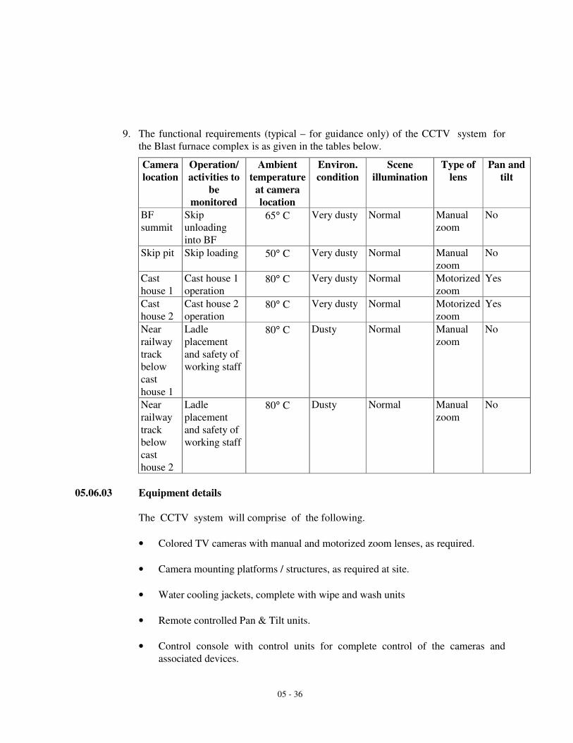
05 - 36
9. The functional requirements (typical – for guidance only) of the CCTV system for
the Blast furnace complex is as given in the tables below.
Camera
location
Operation/
activities to
be
monitored
Ambient
temperature
at camera
location
Environ.
condition
Scene
illumination
Type of
lens
Pan and
tilt
BF
summit
Skip
unloading
into BF
65° C Very dusty Normal Manual
zoom
No
Skip pit Skip loading 50° C Very dusty Normal Manual
zoom
No
Cast
house 1
Cast house 1
operation 80° C Very dusty Normal Motorized
zoom
Yes
Cast
house 2
Cast house 2
operation 80° C Very dusty Normal Motorized
zoom
Yes
Near
railway
track
below
cast
house 1
Ladle
placement
and safety of
working staff
80° C Dusty Normal Manual
zoom
No
Near
railway
track
below
cast
house 2
Ladle
placement
and safety of
working staff
80° C Dusty Normal Manual
zoom
No
05.06.03 Equipment details
The CCTV system will comprise of the following.
• Colored TV cameras with manual and motorized zoom lenses, as required.
• Camera mounting platforms / structures, as required at site.
• Water cooling jackets, complete with wipe and wash units
• Remote controlled Pan & Tilt units.
• Control console with control units for complete control of the cameras and
associated devices.

05 - 37
• Colored TV monitors
• Interconnecting video and control cables
• Un-interrupted power supply unit
• Video distribution amplifiers/ Video cable equalizers, as per requirement.
• All other auxiliary equipment, connectors, erection accessories etc. as
required.
001 TV Camera
The TV cameras will be compact, of rugged design and suitable for industrial
applications.
These will be specially designed and tested to provide continuous good quality video
output throughout wide variations in environment conditions like temperature,
humidity, shock and vibrations and varying light condition prevalent in the Blast
furnace complex.
The cameras will use ½” format interline transfer CCD imager and have virtually
zero lag, no image burns and no geometric distortion. These will be of contemporary
styling and employ complete solid-state circuitry, ensuring high operational
reliability.
The cameras will deliver well defined, clear, high resolution colored picture, with
sufficient contrast to allow for good object recognition even in poor light conditions.
A highly sensitive automatic light compensation circuit will ensure constant video
signal independent of wide variations in light levels.
The cameras will have long life and require virtually zero maintenance in adverse
environmental conditions prevalent in the steel plant.
The TV cameras will also possess the following features :
• High resolution .
• Excellent sensitivity
• Low power consumption.
• Phase adjustable line lock facility.
• All controls like back focus, lens select, phase adjustment, power ON/OFF etc.
will be suitably provided at convenient and easy to adjust locations on the camera.
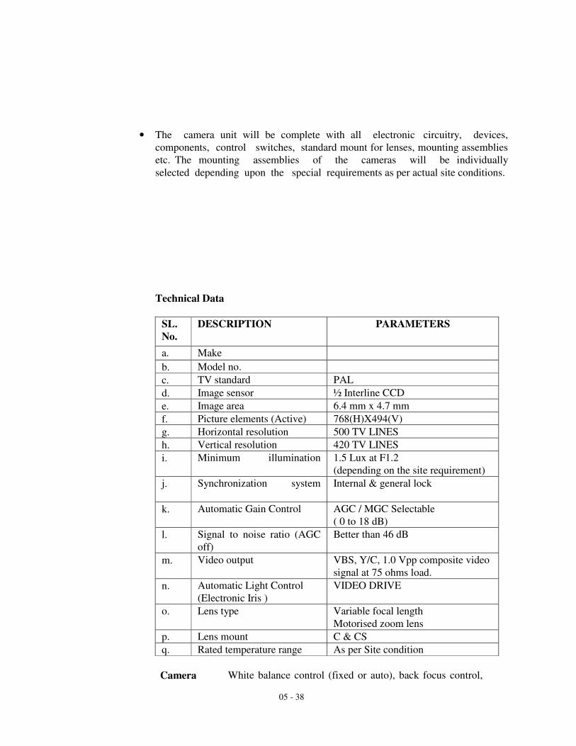
05 - 38
• The camera unit will be complete with all electronic circuitry, devices,
components, control switches, standard mount for lenses, mounting assemblies
etc. The mounting assemblies of the cameras will be individually
selected depending upon the special requirements as per actual site conditions.
Technical Data
SL.
No.
DESCRIPTION PARAMETERS
a. Make
b. Model no.
c. TV standard PAL
d. Image sensor ½ Interline CCD
e. Image area 6.4 mm x 4.7 mm
f. Picture elements (Active) 768(H)X494(V)
g. Horizontal resolution 500 TV LINES
h. Vertical resolution 420 TV LINES
i. Minimum illumination
1.5 Lux at F1.2
(depending on the site requirement)
j. Synchronization system
Internal & general lock
k. Automatic Gain Control AGC / MGC Selectable
( 0 to 18 dB)
l. Signal to noise ratio (AGC
off)
Better than 46 dB
m. Video output VBS, Y/C, 1.0 Vpp composite video
signal at 75 ohms load.
n. Automatic Light Control
(Electronic Iris )
A) VIDEO DRIVE
o. Lens type Variable focal length
Motorised zoom lens
p. Lens mount C & CS
q. Rated temperature range As per Site condition
Camera
White balance control (fixed or auto), back focus control,

05 - 39
Controls lens controls (level and ALC), phase adjustment (0 to 360
degree), back light compensation (on/off), auto shutter
speeds ( 1/50 to 1/10000), fixed shutter speeds (1/120 to
1/4000), sync. mode (internal crystal reference/ line lock),
focus control, AGC on/off switch selection
002 Camera Lens
The camera lens will be suitable for the camera on which it is to be mounted. The
lenses chosen will be fixed focal length/ manual zoom/ remote controlled motorized
zoom type so as to meet the specification requirements. The choice of lenses, their
focal length and viewing angle will be judiciously done for effective monitoring
suited to the specific application requirements in the shop floor. Auto iris lenses
with internal spot filters will be used for varying lighting conditions.
Technical Parameter of ½” Manual zoom / Motorised lens
SL. DESCRIPTION Manual Zoom Motorized Zoom
Make
Model no.
Type of lens - Manual Zoom Motorized Zoom
Lens format ½ “ / 1/3 “ ½” / 1/3 “
Focal length and
aperture
6-60 mm
F1.2 - 560
6-60 mm,
F1.2 - 560
Iris type Auto IRIS Auto IRIS
Type of mount C C / CS
003 Camera Mounting Platform:
The camera mounting platform will be suitable for mounting the camera assembly
on walls / column / structures as per the actual requirements at site and keeping in
view the area to be covered by the individual camera. The mounting will be with
adjustable support so as to have flexibility to move the camera assembly as and when
required. Wherever necessary, the contractor may have to fabricate structures /
vertical poles to mount the cameras. The structure / platforms/ brackets for
mounting all the cameras are included in the scope of the contractor. The contractor
will furnish the complete details of structure / platforms / mountings which will
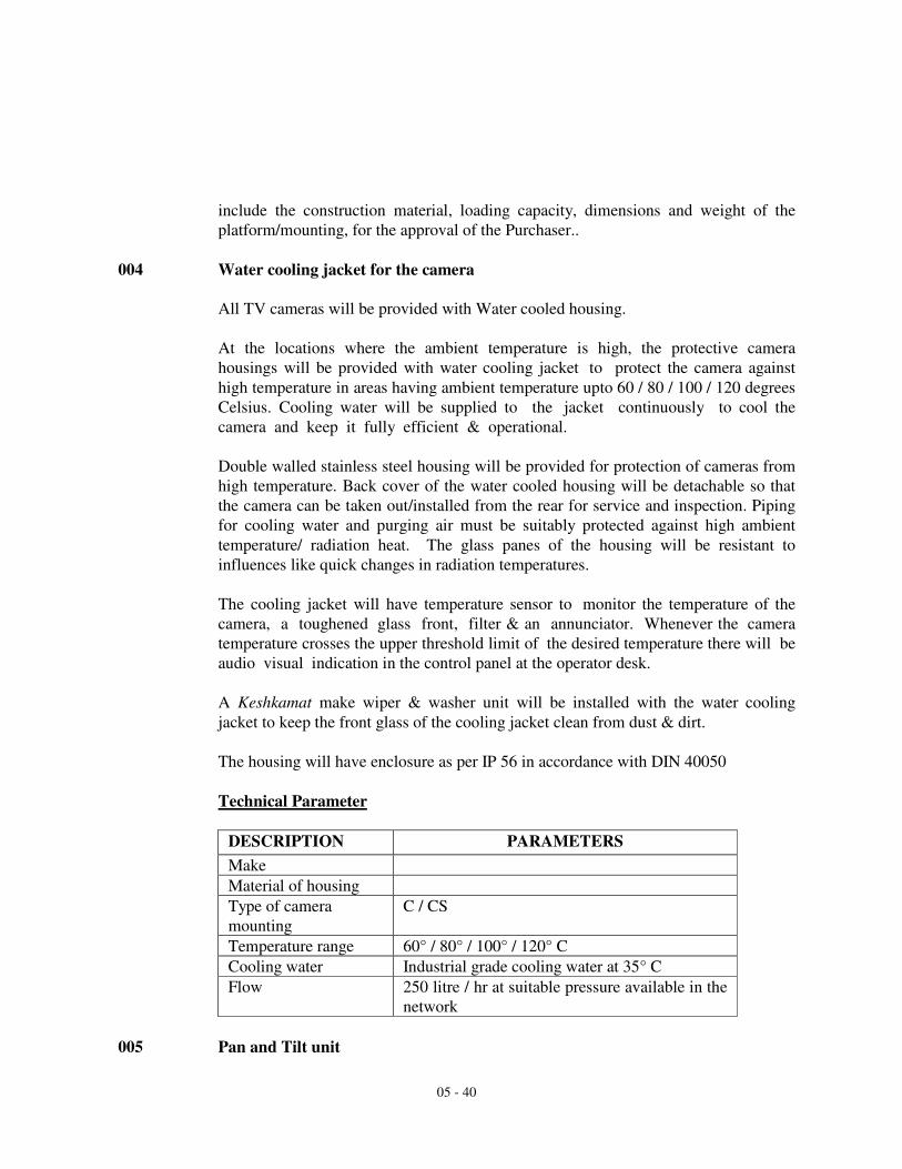
05 - 40
include the construction material, loading capacity, dimensions and weight of the
platform/mounting, for the approval of the Purchaser..
004 Water cooling jacket for the camera
All TV cameras will be provided with Water cooled housing.
At the locations where the ambient temperature is high, the protective camera
housings will be provided with water cooling jacket to protect the camera against
high temperature in areas having ambient temperature upto 60 / 80 / 100 / 120 degrees
Celsius. Cooling water will be supplied to the jacket continuously to cool the
camera and keep it fully efficient & operational.
Double walled stainless steel housing will be provided for protection of cameras from
high temperature. Back cover of the water cooled housing will be detachable so that
the camera can be taken out/installed from the rear for service and inspection. Piping
for cooling water and purging air must be suitably protected against high ambient
temperature/ radiation heat. The glass panes of the housing will be resistant to
influences like quick changes in radiation temperatures.
The cooling jacket will have temperature sensor to monitor the temperature of the
camera, a toughened glass front, filter & an annunciator. Whenever the camera
temperature crosses the upper threshold limit of the desired temperature there will be
audio visual indication in the control panel at the operator desk.
A Keshkamat make wiper & washer unit will be installed with the water cooling
jacket to keep the front glass of the cooling jacket clean from dust & dirt.
The housing will have enclosure as per IP 56 in accordance with DIN 40050
Technical Parameter
DESCRIPTION PARAMETERS
Make
Material of housing
Type of camera
mounting
C / CS
Temperature range 60° / 80° / 100° / 120° C
Cooling water Industrial grade cooling water at 35° C
Flow 250 litre / hr at suitable pressure available in the
network
005 Pan and Tilt unit

05 - 41
The pan and tilt unit will comprise of pan & tilt head and control unit. The pan and
tilt head will be remotely controlled from the control unit
The pan & tilt head will be heavy/ medium duty type, rugged in construction and
smooth in operation. The unit will be used to cover large area of interest for
surveillance in different directions, as required by the operator.
The unit will be suitable for mounting on walls / column / structures / hanging
from ceiling as per the site requirements. The unit will have complete freedom of
movement throughout the entire pan & tilt scan. The unit will be completely sealed
for all weather proof use.
The pan and tilt units will be designed so as to ensure long operational life. The
units will employ electric motors with quick reversibility and dynamic braking
characteristics, have rugged worm gears assembly to minimize backlash and ensure
drift free operation. It will be possible with ease to reposition the cameras field of
view at any time. The limit switches will be employed to control the field of scan.
The unit will have manual over ride on the auto mode to enable the operator to
choose the area of scan as and when required.
The control unit will be installed in the control room, as per the requirement. It
will be designed to move the camera both in horizontal and vertical planes.
Technical data
DESCRIPTION PARAMETERS
Make
Model no.
Angular travel in horizontal
plane
0-355 deg.
Angular travel in vertical plane +/-90 deg.
Operating speed–Panning (no
load condition)
6 deg./ sec
Operating speed – Tilting (no
load condition)
6 deg./sec
Maximum load (Load rating to
be compatible for camera, lens
and housing fitted)
Braking Mechanical friction type
Construction material Main body - Aluminium casting
Cover – MS sheet fabricated
Platform – Cast Al & Cast iron.
Whether heavy-duty/medium Heavy-duty
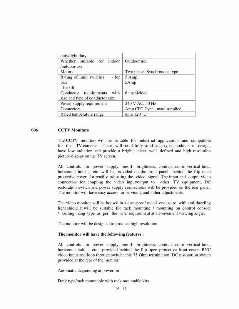
05 - 42
duty/light duty
Whether suitable for indoor
/outdoor use
Outdoor use
Motors Two phase, Synchronous type
Rating of limit switches - for
pan
- for tilt
5 Amp
5Amp
Conductor requirements with
size and type of conductor size
6 unshielded
Power supply requirement 240 V AC, 50 Hz
Connectors Amp CPC Type , mate supplied
Rated temperature range upto 120° C
006 CCTV Monitors
The CCTV monitors will be suitable for industrial applications and compatible
for the TV cameras. These will be of fully solid state type, modular in design,
have low radiation and provide a bright, clear, well defined and high resolution
picture display on the TV screen.
All controls for power supply on/off, brightness, contrast, color, vertical hold,
horizontal hold , etc. will be provided on the front panel behind the flip open
protective cover for readily adjusting the video signal. The input and output video
connectors for coupling the video input/output to other TV equipment, DC
restoration switch and power supply connections will be provided on the rear panel.
The monitor will have easy access for servicing and other adjustments.
The video monitor will be housed in a dust-proof metal enclosure with anti-dazzling
light shield. It will be suitable for rack mounting / mounting on control console
/ ceiling hang type as per the site requirement at a convenient viewing angle.
The monitor will be designed to produce high resolution.
The monitor will have the following features :
All controls for power supply on/off, brightness, contrast, color, vertical hold,
horizontal hold , etc. provided behind the flip open protective front cover. BNC
video input and loop through switcheable 75 Ohm termination, DC restoration switch
provided at the rear of the monitor.
Automatic degaussing at power on
Desk type/rack mountable with rack mountable kits

05 - 43
Quick start
Easy access for servicing and adjustments
Technical Parameter
DESCRIPTION PARAMETERS
Make
Model no.
Picture tube size 14 inches / 19 inches
Scanning system PAL
Horizontal resolution 460 TV lines (Centre)
Vertical resolution 420 TV lines
Video input 1.0 V pp
Input impedance 75 ohms
Power consumption 60 W
Controls : Power on/off, LED pilot light, brightness, color, contrast, V-
hold, H- hold, impedance – 75 ohm/ high SW, DC
restoration SW etc.
007 Control Console
The control panel will facilitate easy operation and enable the operator to have a
clear and easy view of the pictures transmitted by various cameras.
The design of control unit panel with control devices, switches, keys and other
associated equipment will provide the convenience of monitoring and control of
the system in a most efficient manner.
All remote controls of camera, motorized zoom lens, pan & tilt, control of blower
unit, wiper & washer unit of the water cooling jacket and it's associated equipment
will be mounted on one desk mounted type console and will be installed in the
control room of Blast furnace.

05 - 44
The control panel will indicate the temperature of the camera (the temperature
inside the water cooling jacket) & there will be an audio visual indication in case
the temperature violates the desired limits.
The control panel will be rugged in construction and layout of devices, components
& circuitry facilitate easy accessibility for servicing and maintenance.
The TV monitors will be mounted on the rack/ on table top / the hanging from the
ceiling of the control pulpits at a convenient viewing angle. Control room at
Video monitor hangers, wherever required, will be suitably provided
008 Video Cable Equalizers
The video cable equalizers will be used to compensate for high frequency losses due
to long runs of coaxial cable used between the camera and video monitor.
009 Interconnecting Cables
The inter connection cables will include :-
Coaxial cable for transmission of video signal from camera to the monitor, via. the
video switching / distribution unit, as required.
Multi-core control cable for remote control of camera and pan & tilt unit through
remote control units from the operator console, as required.
Power supply cable for providing power supply to various equipment.
Multi-core control cable for annunciation of temperature condition in water cooling
jacket.
The supplier will furnish detailed technical specification of various types of
cables proposed to be used for providing interconnection between various units of
the CCTV system.
010 Equipment power supplies
All the equipment of the CCTV system will work on 240 V±10 %, 50 Hz±2 Hz,
single phase AC power supply which will be made available to the contractor only at
control room. No local power supply will be provided by the purchaser for
individual TV cameras or other units of the system.
05 - 45
It will be the responsibility of the contractor to make power supply provision for
various equipment of the CCTV system from these sources as per their input
requirement. The contractor will also supply and install the necessary power supply
equipment required for feeding stabilized power supply to CCTV system.
011 Uninterrupted Power Supply System
An uninterrupted power supply (UPS) system will be supplied and installed by
the contractor for providing necessary stabilized and continuos power supply to the
complete equipment at the control center. The power supply equipment will
include all transformers, chargers, Ni - Cd battery bank (for 30 minutes back up),
inverters, distribution boards etc. including all necessary cabling and other
accessories.
The UPS system will be designed such that failure of a major component will not
affect the system availability while repairs are in progress. The power supply system
will be provided with all necessary alarms for enabling the operation staff
to detect any malfunctioning or failure of the power supply system The UPS will
be suitably rated to meet the total power requirement of system.
05.07 CABLE LAYING SPECIFICATION
05.07.01 General
Cable shall be laid on racks of concrete cable trench/cable channels/cable tunnels,
directly buried in underground trench, in ducts, on racks / trays of the conveyor
galleries, in GI pipes, in GI conduits (conduit embedded in walls / exposed on
surface), in PVC casings and clamped along structure or buildings as per the site
conditions and requirements.
05.07.02 Type of cable to be used
Petroleum jelly filled armoured cable shall be used when the cable is to be directly
buried in underground trenches.
Armoured PVC cable shall be used when the cable is to be laid in concrete cable
trench / cable tunnels / overhead cable galleries / directly clamped on the walls or
structures.
All PVC cables shall be Fire retardant low smoke (FRLS) type.
For internal distribution purpose the cables from the distribution box to the individual
subscriber, the cables shall be laid in the following manner :
05 - 46
In office buildings for unarmoured communication cables shall generally be laid
through PVC casing / concealed conduits embedded in walls.
In shop floors, substations, control rooms etc communication cables shall generally be
taken either through surface conduits along wall/structure or through concealed
conduits embedded in wall,
05.07.03 Type of cable laying
1. For interplant cabling communication cables shall generally be laid in the manner as
follows :
Laid on the racks of the interplant concrete cable trench.
Directly buried in underground trench.
On the racks of the underground cable tunnels.
On racks / trays of the overhead cable galleries.
In concrete ducts / pipes buried in ground where direct burial are not possible due to
presence of other service lines.
Directly on the walls / structures by clamping the cable on to the walls.
2. Laying of cables shall include different types & sizes of cables required as specified in
the specification.
3. The tenderer shall have to do any fabrication / modification work involving erection
of cable supporting structures(if required), welding, gas cutting etc. at site as per the
actual requirements.
4. The installation work shall be carried out in a neat manner by skilled, experienced and
competent workmen, with experience in jointing and termination of communication
cables.
5. The following general laying conditions / guidelines shall be followed by the tenderer
for laying of cables :
6. All cables shall be tested for proper continuity and insulation before laying.
7. Care shall be taken that kinks, twists or mechanical damage do not occur to the cables
during laying.
05 - 47
8. All bends in cables shall be made with due consideration to the minimum permissible
bending radius of the cables.
9. Care shall be taken that during laying of cables, loops are not formed.
10. While pulling of cables, it shall not be allowed to be dragged along the ground or
over a second cable already laid.
11. Cable markers shall be provided on either side of road crossings, at each turning and
at regular intervals of 40/50 metres on straight runs for underground cables.
12. Joint markers shall be provided at every joint on the cable.
13. Where cables are required to cross under roads, surface drains and pipelines, they
shall be taken through GI pipes.
14. Whenever cables leaves the trench for entering the buildings, they shall be specially
protected by means of GI pipe. After cable laying these shall be sealed with bitumen
or epoxy compound to make them fully water tight and vermin proof.
15. Cables in underground trench shall be laid with sufficient slack.
16. While taking exposed cables along walls or columns, these shall be fixed at a
sufficient height for avoiding damage from operation or handling.
17. In no case the cables shall be left in excavation without providing for satisfactory
sealing.
18. All cable openings in the equipment etc. shall be sealed and made vermin proof. All
cable openings in walls and floors shall be repaired sealed after laying of cables.
19. Special care shall be taken for protection of cables against mechanical damage. RCC
slabs of 40mm thickness shall be provided in the trench to protect the cables from any
mechanical damage.
20. All cables shall be tested for their healthy condition after laying.
05.07.04 Laying of Cables in Underground Trenches:
Excavation of trench of 1.00 M depth shall be done as per the standard norms.
80mm thick river sand cushion shall be provided below the cable.
Cable of the mentioned size shall be laid above this sand layer.
05 - 48
80mm thick river sand cushion shall be provided above the cable.
RCC protection slab shall be provided as per requirement above the sand cushion.
Cable identification tags shall be provided at every 15 M interval in case of straight
runs.
Cable marker shall be provided at every bend, at every road crossings and at every
40/50 M interval on straight runs.
05.07.05 Laying of Cables on Walls & Structures:
Perforated aluminum tray with angle iron support shall be provided (wherever
required) for cable laying.
Smaller size cables shall be clamped on to the walls / structures. Clamps shall be
provided at 1 meter interval.
Plastic / Aluminum cable ties shall be provided at one meter interval.
Cable identification tags on fibre glass/aluminum with nylon cord shall be provided at
every 15 M interval.
05.07.06 Laying of Cables in GI Pipes / GI Conduits:
Only one cable shall be taken in one pipe in the case of laying cables through GI pipes
/ conduits. When it is found desirable to install several cables in one pipe total
section of cable shall not exceed 40% of the GI pipe internal cross section.
05.07.07 Laying of GI Pipes / Conduits :
All conduits/pipes shall be neatly run and evenly placed.
Jointing of conduits / pipes shall be done only in straight portions the tenderer shall
have at site bending facility for conduits / pipes and dies for threading of conduits /
pipes.
Junction boxes shall be provided after every 10 M run of conduits / pipes, at every
bend, at every location where the telephone provision is envisaged.

05 - 49
Ends of conduits shall be provided with threads so that DBs / CTBs / conduits /
accessories can be attached at a later date.
No separate bend pieces shall be used, pipes/ conduits shall be bent wherever
required.
The bending diameter shall not be less than six times the diameter of the conduit /
pipes.
Exposed portion of the thread shall be painted with non-corrosive paint.
The end threads of conduits which will be left for extension / mounting of accessories
shall be protected with grease or any other lubricant to prevent rust / corrosion.
16 SWG steel wires shall be provided inside each conduit for pulling cables.
Conduit shall be laid concealed in wall / column at a height of 200 mm from finished
floor level.
05.07.08 Installation of Distribution cabinet :
Installation of cabinets shall be done on RCC foundations of 600mm above ground
level.
Requisite number of suitably bent GI pipes shall be provided for incoming and
outgoing cables.
Termination and sealing of cables inside the cabinet shall be done as per ITD
specification.
Provision shall be kept for terminating jumper wires.
05.07.09 Installation of Distribution boxes :
Grouting of the support/welding to iron structures, with frames, shall be done
wherever necessary.
Cable glands shall be provided and cables shall be terminated inside the
Distribution Boxes as per ITD specification.
Cables shall be tested at both the ends after termination.