
Near-field imaging of optical antenna modes in the mid...
11
Near-field imaging of optical antenna modes in the mid-infrared Robert L. Olmon 1,2 , Peter M. Krenz 3 , Andrew C. Jones 1 , Glenn D. Boreman 3 , Markus B. Raschke 1,† 1 Department of Chemistry, University of Washington, Seattle, WA98195 2 Department of Electrical Engineering, University of Washington, Seattle, WA 98195 3 Center for Research and Education in Optics and Lasers (CREOL), University of Central Florida, Orlando, FL 32816 [email protected] Abstract: Optical antennas can enhance the coupling between free-space propagating light and the localized excitation of nanoscopic light emitters or receivers, thus forming the basis of many nanophotonic applications. Their functionality relies on an understanding of the relationship between the geometric parameters and the resulting near-field antenna modes. Using scattering-type scanning near-field optical microscopy (s-SNOM) with interferometric homodyne detection, we investigate the resonances of linear Au wire antennas designed for the mid-IR by probing specific vector near-field components. A simple effective wavelength scaling is observed for single wires with λ eff = λ /(2.0 ± 0.2), specific to the geometric and material parameters used. The disruption of the coherent current oscillation by introducing a gap gives rise to an effective multipolar mode for the two near-field coupled segments. Using antenna theory and numerical electrodynamics simulations two distinct coupling regimes are considered that scale with gap width or reactive near-field decay length, respectively. The results emphasize the distinct antenna behavior at optical frequencies compared to impedance matched radio frequency (RF) antennas and provide experimental confirmation of theoretically predicted scaling laws at optical frequencies. © 2008 Optical Society of America OCIS codes: (260.3910) Metal optics; (260.5740) Resonance; (310.6628) Subwavelength structures; (180.4243) Near-field microscopy References and links 1. T. H. Taminiau, F. D. Stefani, F. B. Segerink, and N. F. van Hulst, “Optical antennas direct single-molecule emission,” Nat. Photonics 2, 234–237 (2008). 2. V. Giannini and J. A. S´ anchez-Gil, “Excitation and emission enhancement of single molecule fluorescence through multiple surface-plasmon resonances on metal trimer nanoantennas,” Opt. Lett. 33, 899–901 (2008). 3. T. H. Taminiau, R. J. Moerland, F. B. Segerink, L. Kuipers, and N. F. van Hulst, “Lambda/4 resonance of an optical monopole antenna probed by single molecule fluorescence,” Nano. Lett. 7, 28–33 (2007). 4. S. K¨ uhn, U. H˚ akanson, L. Rogobete, and V. Sandoghdar, “Enhancement of single-molecule fluorescence using a gold nanoparticle as an optical nanoantenna,” Phys. Rev. Lett. 97, 017402–4 (2006). 5. J. Aizpurua, G. W. Bryant, L. J. Richter, F. J. Garc´ ıa de Abajo, B. K. Kelley, and T. Mallouk, “Optical properties of coupled metallic nanorods for field-enhanced spectroscopy,” Phys.Rev. B 71, 235420 (2005). 6. P. Krenz, J. Alda, and G. Boreman, “Orthogonal infrared dipole antenna,” Infrared Phys. Technol. 51, 340–343 (2008). 7. C. Fumeaux, M. A. Gritz, I. Codreanu, W. L. Schaich, F. J. Gonz´ alez, and G. D. Boreman, “Measurement of the resonant lengths of infrared dipole antennas,” Infrared Phys. Technol. 41, 271–281 (2000). #101966 - $15.00 USD Received 24 Sep 2008; revised 10 Nov 2008; accepted 11 Nov 2008; published 24 Nov 2008 (C) 2008 OSA 8 December 2008 / Vol. 16, No. 25 / OPTICS EXPRESS 20295
Transcript of Near-field imaging of optical antenna modes in the mid...

Near-field imaging of optical antennamodes in the mid-infrared
Robert L. Olmon1,2, Peter M. Krenz3, Andrew C. Jones1, Glenn D.Boreman3, Markus B. Raschke1,†
1Department of Chemistry, University of Washington, Seattle, WA 981952Department of Electrical Engineering, University of Washington, Seattle, WA 98195
3Center for Research and Education in Optics and Lasers (CREOL), University of CentralFlorida, Orlando, FL 32816
Abstract: Optical antennas can enhance the coupling between free-spacepropagating light and the localized excitation of nanoscopic light emittersor receivers, thus forming the basis of many nanophotonic applications.Their functionality relies on an understanding of the relationship betweenthe geometric parameters and the resulting near-field antenna modes.Using scattering-type scanning near-field optical microscopy (s-SNOM)with interferometric homodyne detection, we investigate the resonances oflinear Au wire antennas designed for the mid-IR by probing specific vectornear-field components. A simple effective wavelength scaling is observedfor single wires with λeff = λ/(2.0± 0.2), specific to the geometric andmaterial parameters used. The disruption of the coherent current oscillationby introducing a gap gives rise to an effective multipolar mode for thetwo near-field coupled segments. Using antenna theory and numericalelectrodynamics simulations two distinct coupling regimes are consideredthat scale with gap width or reactive near-field decay length, respectively.The results emphasize the distinct antenna behavior at optical frequenciescompared to impedance matched radio frequency (RF) antennas and provideexperimental confirmation of theoretically predicted scaling laws at opticalfrequencies.
© 2008 Optical Society of America
OCIS codes: (260.3910) Metal optics; (260.5740) Resonance; (310.6628) Subwavelengthstructures; (180.4243) Near-field microscopy
References and links1. T. H. Taminiau, F. D. Stefani, F. B. Segerink, and N. F. van Hulst, “Optical antennas direct single-molecule
emission,” Nat. Photonics 2, 234–237 (2008).2. V. Giannini and J. A. Sanchez-Gil, “Excitation and emission enhancement of single molecule fluorescence
through multiple surface-plasmon resonances on metal trimer nanoantennas,” Opt. Lett. 33, 899–901 (2008).3. T. H. Taminiau, R. J. Moerland, F. B. Segerink, L. Kuipers, and N. F. van Hulst, “Lambda/4 resonance of an
optical monopole antenna probed by single molecule fluorescence,” Nano. Lett. 7, 28–33 (2007).4. S. Kuhn, U. Hakanson, L. Rogobete, and V. Sandoghdar, “Enhancement of single-molecule fluorescence using a
gold nanoparticle as an optical nanoantenna,” Phys. Rev. Lett. 97, 017402–4 (2006).5. J. Aizpurua, G. W. Bryant, L. J. Richter, F. J. Garcıa de Abajo, B. K. Kelley, and T. Mallouk, “Optical properties
of coupled metallic nanorods for field-enhanced spectroscopy,” Phys. Rev. B 71, 235420 (2005).6. P. Krenz, J. Alda, and G. Boreman, “Orthogonal infrared dipole antenna,” Infrared Phys. Technol. 51, 340–343
(2008).7. C. Fumeaux, M. A. Gritz, I. Codreanu, W. L. Schaich, F. J. Gonzalez, and G. D. Boreman, “Measurement of the
resonant lengths of infrared dipole antennas,” Infrared Phys. Technol. 41, 271–281 (2000).
#101966 - $15.00 USD Received 24 Sep 2008; revised 10 Nov 2008; accepted 11 Nov 2008; published 24 Nov 2008
(C) 2008 OSA 8 December 2008 / Vol. 16, No. 25 / OPTICS EXPRESS 20295

8. N. Yu, E. Cubukcu, L. Diehl, M. A. Belkin, K. B. Crozier, F. Capasso, D. Bour, S. Corzine, and G. Hofler,“Plasmonic quantum cascade laser antenna,” Appl. Phys. Lett. 91, 173113–3 (2007).
9. A. Cvitkovic, N. Ocelic, J. Aizpurua, R. Guckenberger, and R. Hillenbrand, “Infrared imaging of single nanopar-ticles via strong field enhancement in a scanning nanogap,” Phys. Rev. Lett. 97, 060801 (2006).
10. L. Tang, S. E. Kocabas, S. Latif, A. K. Okyay, D.-S. Ly-Gagnon, K. C. Saraswat, and D. A. B. Miller,“Nanometre-scale germanium photodetector enhanced by a near-infrared dipole antenna,” Nat. Photonics 2,226–229 (2008).
11. M. Pelton, J. Aizpurua, and G. Bryant, “Metal-nanoparticle plasmonics,” Laser Photon. Rev. 2, 136–159 (2008).12. J. N. Farahani, D. W. Pohl, H.-J. Eisler, and B. Hecht, “Single quantum dot coupled to a scanning optical antenna:
A tunable superemitter,” Phys. Rev. Lett. 95, 017402–4 (2005).13. S.-D. Liu, M.-T. Cheng, Z.-J. Yang, and Q.-Q. Wang, “Surface plasmon propagation in a pair of metal nanowires
coupled to a nanosized optical emitter,” Opt. Lett. 33, 851–853 (2008).14. In some applications, a low-frequency feed line may be used to extract an electrical signal from an optical
antenna, see, e.g., F. J. Gonzalez and G. D. Boreman, “Comparison of dipole, bowtie, spiral and log-periodic IRantennas,” Infrared Phys. Technol. 46, 418–428 (2005).
15. L. Novotny, “Effective wavelength scaling for optical antennas,” Phys. Rev. Lett. 98, 266802 (2007).16. F. Neubrech, T. Kolb, R. Lovrincic, G. Fahsold, A. Pucci, J. Aizpurua, T. W. Cornelius, M. E. Toimil-Molares,
R. Neumann, and S. Karim, “Resonances of individual metal nanowires in the infrared,” Appl. Phys. Lett. 89,253104–3 (2006).
17. J. Merlein, M. Kahl, A. Zuschlag, A. Sell, A. Halm, J. Boneberg, P. Leiderer, A. Leitenstorfer, and R. Brats-chitsch, “Nanomechanical control of an optical antenna,” Nat. Photonics 2, 230–233 (2008).
18. K. B. Crozier, A. Sundaramurthy, G. S. Kino, and C. F. Quate, “Optical antennas: Resonators for local fieldenhancement,” J. Appl. Phys. 94, 4632–4642 (2003).
19. P. Muhlschlegel, H.-J. Eisler, O. J. F. Martin, B. Hecht, and D. W. Pohl, “Resonant optical antennas,” Science308, 1607 (2005).
20. O. L. Muskens, V. Giannini, J. A. Sanchez-Gil, and J. Gomez Rivas, “Optical scattering resonances of single andcoupled dimer plasmonic nanoantennas,” Opt. Express 15, 17736–17746 (2007).
21. P. J. Schuck, D. P. Fromm, A. Sundaramurthy, G. S. Kino, and W. E. Moerner, “Improving the mismatch betweenlight and nanoscale objects with gold bowtie nanoantennas,” Phys. Rev. Lett. 94, 017402–4, (2005).
22. G. W. Bryant, F. J. Garcıa de Abajo, and J. Aizpurua, “Mapping the plasmon resonances of metallic nanoanten-nas,” Nano. Lett. 8, 631–636 (2008).
23. H. Fischer and O. J. F. Martin, “Engineering the optical response ofplasmonic nanoantennas,” Opt. Express 16,9144–9154 (2008).
24. B. P. Joshi and Q.-H. Wei, “Cavity resonances of metal-dielectric-metal nanoantennas,” Opt. Express 16, 10315–10322 (2008).
25. E. R. Encina and E. A. Coronado, “Resonance conditions for multipole plasmon excitations in noble metalnanorods,” J. Phys. Chem. C 111, 16796–16801 (2007).
26. F. Keilmann and R. Hillenbrand, “Near-field microscopy by elastic light scattering from a tip,” Philos. Trans. R.Soc. London Ser. A 362, 787–805 (2004).
27. K. G. Lee, H. W. Kihm, Kihm J. E., Choi W. J., Kim H., Ropers C., Park D. J., Yoon Y. C., Choi S. B., Woo D.H., Kim J., Lee B., Park Q. H., Lienau C., and Kim D. S, “Vector field microscopic imaging of light,” NaturePhoton. 1, 53–56 (2007).
28. M. Rang, A. C. Jones, F. Zhou, Z.-Y. Li, B. J. Wiley, Y. Xia, and M. B. Raschke, “Optical near-field mapping ofplasmonic nanoprisms,” Nano. Lett. 8, 3357–3363 (2008).
29. M. B. Raschke, L. Molina, T. Elsaesser, D. H. Kim, W. Knoll, and K. Hinrichs, “Apertureless near-field vi-brational imaging of block-copolymer nanostructures with ultrahigh spatial resolution,” Chem. PhysChem. 6,2197–2203 (2005).
30. Since the detected signal is a demodulation of the tip-sample dither frequency, it actually represents the near-fieldgradient within the dither region rather than just the near-field intensity.
31. L. Gomez, R. Bachelot, A. Bouhelier, G. P. Wiederrecht, S. H. Chang, S. K. Gray, F. Hua, S. Jeon, J. A. Rogers,M. E. Castro, S. Blaize, I. Stefanon, G. Lerondel, and P. Royer, “Apertureless scanning near-field optical mi-croscopy: a comparison between homodyne and heterodyne approaches,” J. Opt. Soc. Am. B 23, 823–833 (2006).
32. T. Taubner, R. Hillenbrand, and F. Keilmann, “Performance of visible and mid-infrared scattering-type near-fieldoptical microscopes,” J. Microsc. 210, 311–314 (2003).
33. In addition, a backscattered far-field background leads to a self-homodyne signal amplification with in generalunspecified phase [34]. For weak sample scattering (this work) or strongly resonant (e.g., plasmonic) excitation[28], spatial phase variations of this background can be neglected resulting in a mere constant s-SNOM signaloffset at constant phase.
34. M. B. Raschke and C. Lienau, “Apertureless near-field optical microscopy: Tip–sample coupling in elastic lightscattering,” Appl. Phys. Lett. 83, 5089–5091 (2003).
35. For details on phase-resolved imaging of IR active nanostructures, see A. Jones, R. Olmon, S. Skrabalak, Y. Xia,and M. Raschke (in preparation).
#101966 - $15.00 USD Received 24 Sep 2008; revised 10 Nov 2008; accepted 11 Nov 2008; published 24 Nov 2008
(C) 2008 OSA 8 December 2008 / Vol. 16, No. 25 / OPTICS EXPRESS 20296
36. C. Balanis, Antenna Theory: Analysis and Design. John Wiley & Sons, Inc., second edition, 1997.37. W. L. Stutzman and G. A. Thiele, Antenna Theory and Design. John Wiley & Sons, Inc., second edition, 1981.38. W. Rechberger, A. Hohenau, A. Leitner, J. R. Krenn, B. Lamprecht, and F. R. Aussenegg, “Optical properties of
two interacting gold nanoparticles,” Optics Communications 220, 137–141 (2003).39. S. J. Orfanidis, Electromagnetic Waves and Antennas. Online book, retrieved August 2008. http://www.
ece.rutgers.edu/∼{}orfanidi/ewa/.40. G. V. Borgiotti, “A novel expression for the mutual admittance of planar radiating elements,” IEEE Trans.
Antennas Propag. AP-16, 329 (1968).41. T. Søndergaard and S. I. Bozhevolnyi, “Strip and gap plasmon polariton optical resonators,” Phys. Status Solidi
B 245, 9–19 (2008).42. C. C. Neacsu, J. Dreyer, N. Behr, and M. B. Raschke, “Scanning-probe raman spectroscopy with single-molecule
sensitivity,” Phys. Rev. B 73, 193406–4 (2006).43. A. Hartschuh, E. J. Sanchez, X. S. Xie, and L. Novotny, “High-resolution near-field raman microscopy of single-
walled carbon nanotubes,” Phys. Rev. Lett. 90, 095503 (2003).44. R. Hillenbrand and F. Keilmann, “Optical oscillation modes of plasmon particles observed in direct space by
phase-contrast near-field microscopy,” Appl. Phys. B 73, 239–243 (2001).45. R. Ossikovski, Q. Nguyen, and G. Picardi, “Simple model for the polarization effects in tip-enhanced raman
spectroscopy,” Phys. Rev. B 75, 045412 (2007).46. R. Hillenbrand, private communication, July 2008.47. A. Alu and N. Engheta, “Tuning the scattering response of optical nanoantennas with nanocircuit loads,” Nature
Photon. 2, 307–310 (2008).48. M. Sukharev and T. Seideman, “Phase and polarization control as a route to plasmonic nanodevices,” Nano.
Lett. 6, 715–719 (2006).
1. Introduction
Expanding the realm of geometric optics, optical antennas provide a means of focusing radiantvisible and infrared (IR) light down to nanometer length scales. This has potential for a widerange of novel photonic applications including chemical [1,2,3,4,5] and thermal sensors [6,7],near-field microscopy [8,9], nanoscale photodetectors [10], and plasmonic devices [11,12,13].However, addressing the up to several orders of magnitude dimensional mismatch between theemitter or receiver in the form of molecules, quantum dots, or waveguides on the one hand, andthe associated wavelengths of the radiation on the other has remained a primary challenge. Withoptical antennas, this challenge typically needs to be met by through-space near-field couplingand not by a feed line from the receiver or emitter as in the radio frequency (RF) case [14]. Byinteracting with nanoscale structures through the near-field, one may take advantage of spatiallocalization and field enhancement on length scales comparable to the size of the nanoscopicsource. Therefore, in contrast to RF antenna designs, where the focus is on optimizing far-fieldcharacteristics in order to obtain better long distance transmission and reception performance,optical antenna designs must first emphasize the near-field behavior.
Like RF antennas, optical antennas are resonant structures responding to specific frequen-cies through both the geometrical and material characteristics of the antennas and their envi-ronments [16, 17, 18, 19, 15, 3, 20, 21]. However, at optical frequencies, different scaling lawsarise associated with the finite skin depth and corresponding resistive losses, finite aspect ratiosand an inhomogeneous dielectric environment. Far-field spectral studies [16, 17, 21, 19, 20, 18]and theoretical modeling [22, 23, 24, 25] have already addressed several fundamental aspectsof optical antennas. Yet, the general understanding of the material and geometrical basis ofoptical antenna modes is still incomplete. In order to gain insight into the near-field antennamodes and their geometric scaling, we measured the evanescent near-field distribution in theform of selected vector-field components of linear IR antennas using scattering-type scanningnear-field optical microscopy (s-SNOM) [26, 27]. The linear wire antenna was chosen as thesimplest implementation of an optical antenna to investigate the fundamentals of length scalingand the effect of coupling between adjacent antenna segments. The antennas are designed forthe mid-IR spectral region due to the comparable ease of structure fabrication as compared to
#101966 - $15.00 USD Received 24 Sep 2008; revised 10 Nov 2008; accepted 11 Nov 2008; published 24 Nov 2008
(C) 2008 OSA 8 December 2008 / Vol. 16, No. 25 / OPTICS EXPRESS 20297

Fig. 1. Scattering-type scanning near-field optical microscope (s-SNOM) with interfero-metric homodyne detection to probe specific near-field vector components of optical an-tennas.
the visible spectral range. In addition, IR optical antennas are in great technological need withmany potential applications in chemical spectroscopy, ultrafast IR and THz transient detection,and remote sensing. [10, 6, 7, 8, 9, 16, 25,5].
2. Experiment and Theory
Au wire antennas were fabricated by electron beam lithography onto native oxide covered Siwafers (resistivity ρ = 3− 6kΩ · cm). The wafers were metalized with a 5 nm seed layer ofTi and 70–80 nm of Au to produce wires approximately 120–150 nm in width, with lengthsranging from 1.6 μm to 7.0 μm, with and without center gaps ranging from 50 nm to 200 nmin width. All structures were separated from each other by 20 μm to ensure mutual decouplingand to minimize extraneous backscattering within the illuminating focal area.
The s-SNOM setup is based on a modified atomic force microscope (AFM, CP-Research,Veeco Inc.) operating in non-contact mode as shown in Fig. 1 and discussed in Ref. [28,29]. Pttips were used in the measurements shown (Si tips were used as well with similar results, thoughwith lower scattering intensities). Both tips exhibit weak dipole-dipole tip-sample coupling, andthus minimize perturbation of the intrinsic field distribution [28]. Excitation is provided by aCO2 laser (λ = 10.6 μm) incident onto the sample via a Cassegrain objective (NA = 0.5) ata 70◦ angle with respect to the surface normal. The elliptical focus has a width at the sampleof ∼13 μm. Polarization selective excitation and tip-scattered near-field detection is performedwith p- and s-polarized light defined with respect to the incidence plane. For excitation, theincident polarization was chosen along the antenna axis. The tip-scattered light is detectedusing a mercury-cadmium-telluride (MCT) photodetector. The optical signal is recorded whileraster scanning the sample and is typically demodulated at the second-harmonic of the tip-dither frequency [30]. Homodyne amplification was performed to extract phase informationfrom the optical near-field signal [31, 32]. To first order, given the scattered near-field E n f
and the reference field Ere f with corresponding phases φn f and φre f , the detected intensityI ≈ |En f |2 + |Ere f |2 + 2|En f ·Ere f |cosΦ, with Φ = φn f − φre f [33]. The in-plane Ey and out-of-plane Ez near-field vector components can be extracted by selective amplification of therespective polarization components by appropriately adjusting the magnitude of the reference
#101966 - $15.00 USD Received 24 Sep 2008; revised 10 Nov 2008; accepted 11 Nov 2008; published 24 Nov 2008
(C) 2008 OSA 8 December 2008 / Vol. 16, No. 25 / OPTICS EXPRESS 20298
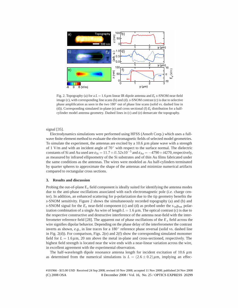
Fig. 2. Topography (a) for a L = 1.6 μm linear IR dipole antenna and Ez s-SNOM near-fieldimage (c), with corresponding line scans (b) and (d). s-SNOM contrast (c) is due to selectivephase amplification as seen in the two 180◦ out of phase line scans (solid vs. dashed line in(d)). Corresponding simulated in-plane (e) and cross sectional (f) Ez distribution for a half-cylinder model antenna geometry. Dashed lines in (c) and (e) demarcate the topography.
signal [35].Electrodynamics simulations were performed using HFSS (Ansoft Corp.) which uses a full-
wave finite element method to evaluate the electromagnetic fields of selected model geometries.To simulate the experiment, the antennas are excited by a 10.6 μm plane wave with a strengthof 1 V/m and with an incident angle of 70◦ with respect to the surface normal. The dielectricconstants of Si and Au used are εSi = 11.7+ i1.52x10−5 and εAu =−4790+ i4270, respectively,as measured by infrared ellipsometry of the Si substrates and of thin Au films fabricated underthe same conditions as the antennas. The wires were modeled as Au half-cylinders terminatedby quarter spheres to approximate the shape of the antennas and minimize numerical artifactscompared to rectangular cross sections.
3. Results and discussion
Probing the out-of-plane Ez field component is ideally suited for identifying the antenna modesdue to the anti-phase oscillations associated with each electromagnetic pole (i.e. charge cen-ter). In addition, an enhanced scattering for p-polarization due to the tip geometry benefits thes-SNOM sensitivity. Figure 2 shows the simultaneously recorded topography (a) and (b) ands-SNOM signal for the Ez near-field component (c) and (d) as probed under the s inpout polar-ization combination of a single Au wire of length L = 1.6 μm. The optical contrast (c) is due tothe respective constructive and destructive interference of the antenna near-field with the inter-ferometer reference field [28]. The apparent out of phase oscillations of the E z field across thewire signifies dipolar behavior. Depending on the phase delay of the interferometer the contrastinverts as shown, e.g., in line traces for a 180◦ reference phase reversal (solid vs. dashed linein Fig. 2(d)). For comparison, Figs. 2(e) and 2(f) show the corresponding simulated monomerfield for L = 1.6 μm, 20 nm above the metal in-plane and cross-sectioned, respectively. Thehighest field strength is located near the wire ends with a near-linear variation across the wire,in excellent agreement with the experimental observation.
The half-wavelength dipole resonance antenna length for incident excitation of 10.6 μmas determined from the numerical simulations is L = (2.6 ± 0.2)μm, implying an effec-
#101966 - $15.00 USD Received 24 Sep 2008; revised 10 Nov 2008; accepted 11 Nov 2008; published 24 Nov 2008
(C) 2008 OSA 8 December 2008 / Vol. 16, No. 25 / OPTICS EXPRESS 20299

Fig. 3. Topography (a) and Ez s-SNOM signal (b) for a L = 5.0 μm antenna showing thefirst higher order mode corresponding to L ≈ λeff. The resulting quadrupole oscillation isreproduced in the corresponding Ez-field simulation (c) showing enhanced field strength atthe wire ends.
tive wavelength of approximately λeff = (5.2± 0.4)μm corresponding to a scaling factor ofλ/λeff = 2.0±0.2 for the geometric and material parameters used. To arrive at this value, theinput impedances for a series of center-fed antennas with lengths ranging from 2.0 μm to 5.0μm were computed with a step size of 10 nm. Antenna resonance then corresponds to an inputreactance of X = 0Ω. The resonant length of ∼ 2.6 μm is found to be in good agreement withresults obtained for related geometries studied [16, 18].
This value can also be compared with an analytic scaling approximation [15] using an ef-fective homogeneous dielectric constant for the surrounding medium of the antenna. Assumingan arithmetic mean of the dielectric constants of Si and air ((εSi + εair)/2 = 6.35) results inan effective wavelength of ∼ 3.6 μm. Considering the geometric mean (
√εSiεair = 3.42), the
effective wavelength is ∼ 5.1 μm, a value close to the numerical results above.These effective wavelengths are considerably reduced compared to the free space wavelength
of 10.6 μm. The difference can be attributed to the observations made previously, noting thatthe resonance wavelength is reduced due to the ohmic loss in the metal at optical frequencies,the dielectric properties of the substrate, and the finite antenna width [15, 7, 16, 18].
A dipole behavior for single wires can still be discerned in s-SNOM measurements of Auwires with lengths greater than the dipole resonance length. However, an increasingly asym-metrically distorted Ez distribution results, as has been seen in measurements for antennas oflengths up to 3.4 μm (data not shown), which is the longest measured structure still supportinga dipole-like field distribution. If the length of the antenna is extended further, multiple half-wavelength current oscillations develop on the antenna for a given excitation frequency withresonances L ≈ n×λeff/2 with n = 1,2... [36]. The first higher order mode (n = 2) correspond-ing to the L ≈ λeff resonance is seen in Fig. 3 for a wire of length L = 5.0 μm, correspondingto the theoretically predicted mode at λeff = (5.2± 0.4)μm as discussed above. The two-foldmaxima and minima observed for the Ez field represent a quadrupole excitation as also seen incorresponding numerical simulations for the same geometry (c). The smaller spatial extent andhigher strength of the fields at the wire endpoints, as observed in the experiment, are character-istic for this excitation mode and are also reproduced theoretically.
In classical antenna theory the occurrence of these antenna resonances depends on the inputimpedance at the feed point. Considering the entire transceiver system, including the signalsource or receiver, transmission lines, and the antenna, resonance is achieved when the antennapresents a conjugate input reactance, which ensures maximum power transfer [37]. The sig-
#101966 - $15.00 USD Received 24 Sep 2008; revised 10 Nov 2008; accepted 11 Nov 2008; published 24 Nov 2008
(C) 2008 OSA 8 December 2008 / Vol. 16, No. 25 / OPTICS EXPRESS 20300

Fig. 4. Topography (a) and (b) and Ez s-SNOM signal (c) and (d) for a structure of overalllength L = 2.0 μm with a gap width of 150 nm and corresponding results for a similargeometry of length L = 3.4 μm (e)–(h). Introducing the gap gives rise to a disruption ofthe original dipole resonance and a splitting into two coupled individual dipole modes.Numerical simulations for expected field distributions for Ez (i) and Ey (j).
nificance of the λ/2 antenna length is merely that such an antenna presents nearly zero inputreactance and approximately 75Ω input resistance intrinsically, and thus can be made to res-onate easily, and radiate efficiently [36]. However, in the optical regime the currents on thetwo arms of a dimer antenna structure do not interact in the same manner as in the RF. Con-sequently, introducing a so-called “feed gap” into the center of an equivalent half-wave linearoptical antenna is inapplicable in attaining antenna resonance [15].
This is shown in Fig. 4 displaying the topographies and near-field E z distributions for antennastructures of overall length L = 2.0 μm (a)–(d) and L = 3.4 μm (e)–(h) after introducing gapsof 150 nm (with similar results also observed for 100 nm and 40 nm gaps). As is evident fromthe observed field distributions, the antenna current oscillations no longer represent single di-pole excitations as was observed for individual wires of corresponding length. Instead, a dipolebehavior is seen for each of the segments, making the overall optical near-field distribution rem-iniscent to that of a linear quadrupole. This is reflected in corresponding numerical simulationsfor the L = 3.4 μm antenna dimer with a gap of 150 nm (i).
The resulting antenna resonance can be described by two separate, albeit coupled, dipoleantennas. In order to analyze the coupling and its effect on the antenna resonance, given thelinear wire antenna geometry, simple classical RF antenna coupling theory can be adopted.The mutual interaction of the respective antenna electric fields with the underlying currents of
#101966 - $15.00 USD Received 24 Sep 2008; revised 10 Nov 2008; accepted 11 Nov 2008; published 24 Nov 2008
(C) 2008 OSA 8 December 2008 / Vol. 16, No. 25 / OPTICS EXPRESS 20301

Fig. 5. Coupling of two equal-length ideal half-wave coaxial dipole antennas separated bydistance d relative to the wavelength. The coupling is manifested in a change in mutualimpedance |Z21/Z22| (here normalized by the self-impedance at the input) with decreasedseparation distance. The associated oscillatory variations in resonant length converge to thelength of a single resonant dipole.
neighboring antennas is described by their mutual impedance [36]. For two identical coaxialantennas of length l separated by a gap of size d, in the approximation of negligible width ofthe antenna segments, assuming a free space environment, and a sinusoidal current, the mutualimpedance Z21 referred to the input terminals (i.e. the impedance change occurring at the inputof antenna 2 due to the electric field radiated by antenna 1) is given by [39]
Z21 =i√
μ0/ε0
4π sin2(kh)
∫ h
−hF(z)dz, (1)
where h = l/2, μ0 is the vacuum magnetic permeability, ε0 is the electric permittivity, k is thewavenumber of the driving field, and
F(z) =
[e−ik(R−h)
R−h+
e−ik(R+h)
R+h−2cos(kh)
e−ikR
R
]
sin[k(h−|z|)], (2)
with R = z + l + d. While a single antenna is subject to self-impedance only (Z11 or Z22),two antennas undergo a shift in total impedance equal to the sum of the self impedance andthe mutual impedance scaled by the antenna current ratio: Z 2 = Z22 + Z21(I1/I2), where I j
denotes current in wire j. Figure 5 shows the resulting coupling observed as an increased mutualimpedance (shown here normalized to the self impedance, i.e. |Z 21/Z22|), for a pair of collinearideal half-wave antennas as a function of gap width.
Since resonance in RF antennas is dependent on the input impedance of the antenna, cou-pling is associated with resonance shifts. This effect is seen when one compares the resonantlengths (reactance X = 0 Ω) of antennas as a function of separation distance as seen in Fig. 5.The result is a characteristic, though small, oscillation in resonant length converging to that ofa single resonant dipole antenna with length L = 0.4857λ for large separation distances. Thisoscillatory behavior is an interference effect. Considering the 90 ◦ phase difference between an-tenna current and the radiated field, for separation distances of (n+ 1/4)λ (for n = 0,1,2, · · ·),
#101966 - $15.00 USD Received 24 Sep 2008; revised 10 Nov 2008; accepted 11 Nov 2008; published 24 Nov 2008
(C) 2008 OSA 8 December 2008 / Vol. 16, No. 25 / OPTICS EXPRESS 20302

the current in each antenna is in phase with the electric field radiated by the other antenna,and they interact constructively. Conversely, when the antennas are separated by (n + 3/4)λ ,the currents are out of phase with the radiated fields. Both situations lead to a change in inputimpedance which require the antenna length to increase for constructive and decrease for de-structive interference, respectively, in order to achieve resonance. The sharp drop in resonancelength at small separation distances can be attributed to a reactive near-field interaction, whichdominates for distances of r < 0.62
√L3/λ [36]. The mutual impedance effect is particularly
strong when the antennas are oriented side by side, with each antenna located in the directionof maximum radiation of the other. In that case, the mutual impedance significantly exceedsthat of the collinear case [36, 39, 40].
Applying this analysis for the optical regime, both the effective wavelength and changesin the emitted field distribution due to the inhomogeneous dielectric environment and finiteaspect ratio of the antennas have to be considered. Nevertheless, the fundamental couplingmechanism in the form of the field retardation effects is expected to prevail. This is supportedby previous experiments that indicate similar coupling behavior for antennas in the visible andnear-IR [5]. Therefore, this reactive coupling in the coaxial antenna geometry as determinedby the wavelength and the antenna size has only a small effect on the resonance length of theindividual antenna segments. The effective scaling as established for single wires is also directlyapplicable for the individual segments of the coupled dimer antennas.
In addition to this long range interaction a local interaction on much shorter distances occurswhich amounts to an increase in enhancement with decreasing distance [21]. Its magnitude,however, depends sensitively on the local geometric details at the gap, and to first order, isexpected to scale with gap width as the radius of the antenna ends. This can give rise to sub-stantial enhancement values, especially for distances in the range of just several nanometers forcorresponding apex radii as shown in the visible spectral range for collinear wires [19,5,24,41]and bow-tie antennas [21]. Such a geometric dependence is reminiscent of tip-enhanced spec-troscopy where a tip-distance dependence of the enhancement in the gap has been establishedto scale with the radius of the tip apex [34, 42, 43].
This local coupling is expected to manifest itself largely in a distance dependent variationof the Ey field for our geometries as seen in the calculated field distribution in Fig. 4(j). Whilethe strength of the Ez field at the ends dominates over the Ey amplitude in general, Ey in thegap increases rapidly and becomes dominant for gap widths < 200 nm. In contrast, the phasechange of the Ez field across the gap gives rise to Ez = 0 at its center. Hence, enhancement ofEz is spatially less localized and experiences a comparatively small variation as a function ofgap width.
While both the Ez and Ey components hold much promise in controlling light at these sub-wavelength dimensions as determined by the gap width, the enhancement of the E y compo-nent in particular is key for field-enhanced spectroscopies [5, 2], subwavelength emitters [8],and nanometer-scale photodetection [10]. The corresponding experimental observation of thisin-plane field component, however, has remained a major challenge [8, 44]. The experimen-tal difficulties arise due to the relative insensitivity of the tip for scattering s-polarized fieldcomponents. Further, due to the finite taper angle of the tip, depolarization of the dominant p-polarized Ez signal contribution during the scattering process is a concern [45]. This, togetherwith all Ey components across the antenna being in phase, makes assignment of the s-SNOMsignal difficult. In sinsout experiments (see Appendix), contrast is observed with in-phase sig-nal characteristics that would, in principle, be consistent with an Ey assignment. The results,however, have been inconclusive, with no signal observed in the gap or beyond the antennaendpoints. We attribute this to the antenna effect of the tip itself. For long wavelengths the scat-tering of the tip apex for s-polarization becomes increasingly inefficient compared to that for
#101966 - $15.00 USD Received 24 Sep 2008; revised 10 Nov 2008; accepted 11 Nov 2008; published 24 Nov 2008
(C) 2008 OSA 8 December 2008 / Vol. 16, No. 25 / OPTICS EXPRESS 20303

longitudinal p-polarized excitation. This is in contrast to our related experiments for plasmonicnanoparticles in the visible where the Ey component could be identified [28].
Probing a gap field has been reported in recent IR studies of resonant antennas with gaps aslarge as 100 nm fabricated on the facet of a quantum cascade laser (QCL) [8]. In these studies,signals from the gap region as well as from the apex of the outer wire ends dominate the opticalresponse, possibly due to the Ey field. However, no polarization sensitive detection is discussed.Also, despite the expected enhanced tip-scattering sensitivity for polarization parallel with re-spect to the tip axis, as stated by the authors, no signature of the characteristic E z fields abovethe metal wires is detected. It is interesting to note that in recent independent IR experiments inother groups for antenna structures and gap widths with geometries similar to those discussedhere, no significant gap fields could be observed [46].
4. Conclusion
In summary, we have demonstrated selective Ez vector-field probing in the IR at 10.6 μm toobtain modal information of optical wire antennas of various lengths. With an effective wave-length of λeff = (5.2± 0.4)μm, scaling the monomer lengths beyond the half-wavelength di-pole resonance of λeff/2 = (2.6± 0.2)μm, the transition from a dipole to a quadrupole fielddistribution for a L = 5.0 μm monomer was observed. In contrast, the dimers with the individualsegments optically coupled across a small gap were revealed to have a new resonant behavioremerging from a superposition of individual monomer modes, reminiscent of a linear quadru-pole, confirming theoretical predictions. Two manifestations of the coupling could be identifiedfrom the combined experimental, numerical, and analytical antenna theory analysis: resonanteffects due to the current-field interaction as determined by the antenna separation distanceand λeff, and local field enhancement effects determined by separation distances on a lengthscale of tens of nm. These results for linear antennas are fundamental and shall be applicablein general to other antenna geometries and wavelengths. They provide design criteria for morecomplex architectures to optimize the resonant interaction of both incident light with recep-tive devices and the near-field coupling to emissive particles. Further developments in, e.g.,impedance matching techniques for optical antennas [47] and in methods for spatial, temporal,and spectral control of light [48] will enhance the performance of future device applicationsincluding detectors at the nanoscale, chemical spectroscopy and thermal sensing.
Acknowledgments
The authors thank Rainer Hillenbrand, Lukas Novotny, Ralf Vogelgesang, Mikhail Belkin andBrian Lail for valuable discussions. We are indebted to Matthias Rang for indispensable ex-perimental support. Funding from the National Science Foundation (NSF CAREER grant CHE0748226) and support from the Environmental Molecular Sciences Laboratory at Pacific North-west National Laboratory is greatly acknowledged.
Appendix
Here, we provide further details regarding imaging the in-plane E y vector-field components oflinear IR antennas. We have shown the capability of the s-SNOM setup to detect in-plane visi-ble light from plasmonic nanoparticles under otherwise identical experimental conditions [28].Similarly, in the present work experiments were aimed at imaging under s insout polarizationconfigurations to detect the Ey component for the linear antennas in the IR. However, with thes-SNOM tip preferentially scattering p-polarized light, detection of s-polarized light is difficultin general. In Fig. 6, the simultaneously recorded topography (a) and corresponding s-SNOMsignal (b) for the measured Ey near-field component of the L = 1.6 μm monomer are shown
#101966 - $15.00 USD Received 24 Sep 2008; revised 10 Nov 2008; accepted 11 Nov 2008; published 24 Nov 2008
(C) 2008 OSA 8 December 2008 / Vol. 16, No. 25 / OPTICS EXPRESS 20304

Fig. 6. The s-SNOM Ey field component imaged above a monomer antenna of length L =1.6 μm (a) and (b). Corresponding dimer fields for lengths L = 3.35 μm and gap widths of200 μm (c) and (d) and 50 μm (e) and (f). The in-phase nature of the field on the metalis predicted by theory, but off the metal, no field is seen in the gap or beyond the antennaends contrary to theory due to preferential Ez scattering and tip depolarization effects.
together with the same field for the dimer geometries with overall lengths L = 3.4 μm andgap widths 150 nm (c, d) and 40 nm (e, f). All structures exhibit E z components as shown inFig. 2(c) and Figs. 4(c) and 4(g). This has been observed using both Pt as well as Si as the tipmaterial.
The phase behavior, showing in-phase emission for all poles both for the monomer as well asfor the dimers would be consistent with the expected tip-scattered emission due to the E y fieldcomponent. However, the relative strength of the measured field and its spatial distributioncompared to that of the simulated field (see, e.g., Fig. 4(j)) suggest that the signal observed isdominated by a depolarized Ez component.
The absence of any field detected within the gap is notable. Yet, the strong, unambiguousEz optical contrast observed and the near perfect agreement with theory suggest that the corre-sponding Ey field should exist. As already indicated in the manuscript, one possible reason forthe apparent absence of a gap field is the antenna effect of the tip itself. Compared to the visible,as the wavelength of the light extends to the mid-IR, the dimensional mismatch between the tipapex and the wavelength increases. This leads to a decrease in scattering efficiency of the tipapex as the active scattering probe region for s-polarized light compared to p-polarized light.The result is a general insensitivity of s-SNOM using conventional tip geometries for IR fieldspolarized perpendicular to the tip apex.
#101966 - $15.00 USD Received 24 Sep 2008; revised 10 Nov 2008; accepted 11 Nov 2008; published 24 Nov 2008
(C) 2008 OSA 8 December 2008 / Vol. 16, No. 25 / OPTICS EXPRESS 20305


![Mitra, Sreemanta; Srivastava, Divya; Singha, Shib Shankar ... · ARTICLE 2 3 ( 1]]]]] Tailoring phonon modes of few-layered MoS2 by in-plane electric field Sreemanta Mitra]]]1,2](https://static.fdocuments.us/doc/165x107/5faf4994753fe95ae92e8bf5/mitra-sreemanta-srivastava-divya-singha-shib-shankar-article-2-3-1.jpg)


