NE1A Logic Simulator Operation Manual - assets.omron.eu€¦ · The NE1A Logic Simulator is a...
85
NE1A Logic Simulator Cat. No. Z910-E1-02 DeviceNet Safety WS02-CFSC1-E OPERATION MANUAL
Transcript of NE1A Logic Simulator Operation Manual - assets.omron.eu€¦ · The NE1A Logic Simulator is a...
Cat. No. Z910-E1-02
NE1A Logic Simulator
DeviceNet SafetyWS02-CFSC1-E
OPERATION MANUAL

DeviceNet SafetyWS02-CFSC1-ENE1A Logic SimulatorOperation ManualRevised June 2007

iv
Notice:OMRON products are manufactured for use according to proper procedures by a qualified operatorand only for the purposes described in this manual.
The following conventions are used to indicate and classify precautions in this manual. Always heedthe information provided with them. Failure to heed precautions can result in injury to people or dam-age to property.
!DANGER Indicates an imminently hazardous situation which, if not avoided, will result in death orserious injury. Additionally, there may be severe property damage.
!WARNING Indicates a potentially hazardous situation which, if not avoided, could result in death orserious injury. Additionally, there may be severe property damage.
!Caution Indicates a potentially hazardous situation which, if not avoided, may result in minor ormoderate injury, or property damage.
OMRON Product ReferencesAll OMRON products are capitalized in this manual. The word “Unit” is also capitalized when it refers toan OMRON product, regardless of whether or not it appears in the proper name of the product.
The abbreviation “Ch,” which appears in some displays and on some OMRON products, often means“word” and is abbreviated “Wd” in documentation in this sense.
The abbreviation “PLC” means Programmable Controller. “PC” is used, however, in some Program-ming Device displays to mean Programmable Controller.
Visual AidsThe following headings appear in the left column of the manual to help you locate different types ofinformation.
Note Indicates information of particular interest for efficient and convenient opera-tion of the product.
1,2,3... 1. Indicates lists of one sort or another, such as procedures, checklists, etc.
Notation in Operating ProceduresThe following conventions are used in the manual in operating procedures.
Menu items are set in bold-italic text and menu levels are separated by hyphens. Example: “Debug - Input Pulse” indicates selecting “Input Pulse” from the Debug Menu.
Tab, button, and key names are set in bold. Example: OK Button
Other on-screen text is set in bold when necessary for clarity.
Key combinations have been indicated with plus symbols. Example: “Ctrl+M” indicates pressing the M Key while holding down the Ctrl Key.
v

Conditions for Software Application and WarrantyApplication of and warranty for the NE1A Logic Simulator (hereafter “Software”) are bound by the fol-lowing Conditions for Application and Warranty. After-sales service will be provided to the customerbased on the enclosed software user registration and upgrade form.
Conditions for Application and Warranty
1. Copyright
The copyright to the Software, including the contents of all enclosed storage media and manuals,is the property of OMRON Corporation.
2. Copying and Modifying the Software
a. The Software may not be copied in part or whole for any purpose other than as a backup or formodification as described in b, below.
b. The user may modify the Software to implement changes or improvements provided that theuser himself/herself makes these modifications and provided that the modifications are for ap-plication by the user himself/herself. OMRON, however, assumes no responsibility for the re-sults of any modifications made by the used, including defects or damages of any nature.
3. Warranty and After-sales Service
a. If the Software fails to function normally in a manner for which OMRON is responsible, OMRONwill correct or replace the Software free of charge.
b. The warranty in a, above, is valid for one year from the date of purchase.
c. OMRON will provide to customers that return the user registration and upgrade form, informa-tion on any bugs in the program that become known to OMRON and information on softwareupgrades.
d. OMRON assumes no responsibility for the results of the application of the Software and as-sumes no warranty other than that stated here.
4. Third-party Usage
Providing copies of the Software to any third party in any form or by any means is strictly prohib-ited.
Registered TrademarksDeviceNet and DeviceNet Safety are registered trademarks of the ODVA. Windows is a registeredtrademark of the Microsoft Corporation.
OMRON, 2007All rights reserved. No part of this publication may be reproduced, stored in a retrieval system, or transmitted, in any form, orby any means, mechanical, electronic, photocopying, recording, or otherwise, without the prior written permission ofOMRON.
No patent liability is assumed with respect to the use of the information contained herein. Moreover, because OMRON is con-stantly striving to improve its high-quality products, the information contained in this manual is subject to change withoutnotice. Every precaution has been taken in the preparation of this manual. Nevertheless, OMRON assumes no responsibilityfor errors or omissions. Neither is any liability assumed for damages resulting from the use of the information contained inthis publication.
vi
TABLE OF CONTENTS
PRECAUTIONS . . . . . . . . . . . . . . . . . . . . . . . . . . . . . . . . . . . xv1 Intended Audience . . . . . . . . . . . . . . . . . . . . . . . . . . . . . . . . . . . . . . . . . . . . . . . . . . . . . . . . . xvi
2 General Precautions . . . . . . . . . . . . . . . . . . . . . . . . . . . . . . . . . . . . . . . . . . . . . . . . . . . . . . . . xvi
3 Safety Precautions . . . . . . . . . . . . . . . . . . . . . . . . . . . . . . . . . . . . . . . . . . . . . . . . . . . . . . . . . xvi
SECTION 1Overview . . . . . . . . . . . . . . . . . . . . . . . . . . . . . . . . . . . . . . . . . 1
1-1 The NE1A Logic Simulator. . . . . . . . . . . . . . . . . . . . . . . . . . . . . . . . . . . . . . . . . . . . . . . . . . 2
1-2 Features . . . . . . . . . . . . . . . . . . . . . . . . . . . . . . . . . . . . . . . . . . . . . . . . . . . . . . . . . . . . . . . . . 3
1-3 System Requirements . . . . . . . . . . . . . . . . . . . . . . . . . . . . . . . . . . . . . . . . . . . . . . . . . . . . . . 4
SECTION 2Basic Operation. . . . . . . . . . . . . . . . . . . . . . . . . . . . . . . . . . . . 5
2-1 Starting and Exiting the Logic Simulator . . . . . . . . . . . . . . . . . . . . . . . . . . . . . . . . . . . . . . . 6
2-2 NE1A Logic Simulator Window Configuration . . . . . . . . . . . . . . . . . . . . . . . . . . . . . . . . . . 7
2-3 Menus . . . . . . . . . . . . . . . . . . . . . . . . . . . . . . . . . . . . . . . . . . . . . . . . . . . . . . . . . . . . . . . . . . 8
2-4 Pop-up Menus . . . . . . . . . . . . . . . . . . . . . . . . . . . . . . . . . . . . . . . . . . . . . . . . . . . . . . . . . . . . 10
2-5 Tool Bars . . . . . . . . . . . . . . . . . . . . . . . . . . . . . . . . . . . . . . . . . . . . . . . . . . . . . . . . . . . . . . . . 11
2-6 Status Bar. . . . . . . . . . . . . . . . . . . . . . . . . . . . . . . . . . . . . . . . . . . . . . . . . . . . . . . . . . . . . . . . 14
2-7 Simulation Procedure. . . . . . . . . . . . . . . . . . . . . . . . . . . . . . . . . . . . . . . . . . . . . . . . . . . . . . . 15
2-8 Creating Logic Programs. . . . . . . . . . . . . . . . . . . . . . . . . . . . . . . . . . . . . . . . . . . . . . . . . . . . 16
2-9 Creating Simulation Files . . . . . . . . . . . . . . . . . . . . . . . . . . . . . . . . . . . . . . . . . . . . . . . . . . . 17
2-10 Opening Simulation Files . . . . . . . . . . . . . . . . . . . . . . . . . . . . . . . . . . . . . . . . . . . . . . . . . . . 18
2-11 Importing Programs. . . . . . . . . . . . . . . . . . . . . . . . . . . . . . . . . . . . . . . . . . . . . . . . . . . . . . . . 19
2-12 Debugging . . . . . . . . . . . . . . . . . . . . . . . . . . . . . . . . . . . . . . . . . . . . . . . . . . . . . . . . . . . . . . . 21
2-13 Using the Watch Window . . . . . . . . . . . . . . . . . . . . . . . . . . . . . . . . . . . . . . . . . . . . . . . . . . . 22
2-14 Saving Simulation Files . . . . . . . . . . . . . . . . . . . . . . . . . . . . . . . . . . . . . . . . . . . . . . . . . . . . . 26
2-15 Versions . . . . . . . . . . . . . . . . . . . . . . . . . . . . . . . . . . . . . . . . . . . . . . . . . . . . . . . . . . . . . . . . . 27
2-16 Help Display . . . . . . . . . . . . . . . . . . . . . . . . . . . . . . . . . . . . . . . . . . . . . . . . . . . . . . . . . . . . . 28
SECTION 3Debugging with the Logic Window . . . . . . . . . . . . . . . . . . . . 29
3-1 Overview . . . . . . . . . . . . . . . . . . . . . . . . . . . . . . . . . . . . . . . . . . . . . . . . . . . . . . . . . . . . . . . . 30
3-2 Starting and Stopping the Logic Program . . . . . . . . . . . . . . . . . . . . . . . . . . . . . . . . . . . . . . . 31
3-3 Modifying Input Tags . . . . . . . . . . . . . . . . . . . . . . . . . . . . . . . . . . . . . . . . . . . . . . . . . . . . . . 32
3-4 Setting Initial Values . . . . . . . . . . . . . . . . . . . . . . . . . . . . . . . . . . . . . . . . . . . . . . . . . . . . . . . 34
3-5 Setting the Cycle Time Base Value . . . . . . . . . . . . . . . . . . . . . . . . . . . . . . . . . . . . . . . . . . . . 35
3-6 Feedback Settings . . . . . . . . . . . . . . . . . . . . . . . . . . . . . . . . . . . . . . . . . . . . . . . . . . . . . . . . . 36
3-7 Monitoring a User-defined Function Block. . . . . . . . . . . . . . . . . . . . . . . . . . . . . . . . . . . . . . 38
3-8 Zooming In and Out of the Logic Window Display . . . . . . . . . . . . . . . . . . . . . . . . . . . . . . . 39
vii
TABLE OF CONTENTS
SECTION 4Debugging with the Timing Chart Window . . . . . . . . . . . . . 41
4-1 Overview . . . . . . . . . . . . . . . . . . . . . . . . . . . . . . . . . . . . . . . . . . . . . . . . . . . . . . . . . . . . . . . . 42
4-2 Timing Chart Window . . . . . . . . . . . . . . . . . . . . . . . . . . . . . . . . . . . . . . . . . . . . . . . . . . . . . . 43
4-3 Adding to the Timing Chart. . . . . . . . . . . . . . . . . . . . . . . . . . . . . . . . . . . . . . . . . . . . . . . . . . 44
4-4 Inputs to the Timing Chart. . . . . . . . . . . . . . . . . . . . . . . . . . . . . . . . . . . . . . . . . . . . . . . . . . . 45
4-5 Starting and Stopping the Timing Chart . . . . . . . . . . . . . . . . . . . . . . . . . . . . . . . . . . . . . . . . 47
4-6 Importing/Exporting Timing Chart Data . . . . . . . . . . . . . . . . . . . . . . . . . . . . . . . . . . . . . . . . 48
4-7 Printing the Timing Chart . . . . . . . . . . . . . . . . . . . . . . . . . . . . . . . . . . . . . . . . . . . . . . . . . . . 50
4-8 Timing Chart Options . . . . . . . . . . . . . . . . . . . . . . . . . . . . . . . . . . . . . . . . . . . . . . . . . . . . . . 51
4-9 Breakpoints . . . . . . . . . . . . . . . . . . . . . . . . . . . . . . . . . . . . . . . . . . . . . . . . . . . . . . . . . . . . . . 54
4-10 I/O Breakpoint . . . . . . . . . . . . . . . . . . . . . . . . . . . . . . . . . . . . . . . . . . . . . . . . . . . . . . . . . . . . 56
4-11 Zooming In and Out of the Timing Chart Display . . . . . . . . . . . . . . . . . . . . . . . . . . . . . . . . 58
SECTION 5Troubleshooting . . . . . . . . . . . . . . . . . . . . . . . . . . . . . . . . . . . 59
5-1 Operating Errors and Countermeasures. . . . . . . . . . . . . . . . . . . . . . . . . . . . . . . . . . . . . . . . . 60
AppendixA Shortcut Key List . . . . . . . . . . . . . . . . . . . . . . . . . . . . . . . . . . . . . . . . . . . . . . . . . . . . . . . . . 63
Index. . . . . . . . . . . . . . . . . . . . . . . . . . . . . . . . . . . . . . . . . . . . . 67
Revision History . . . . . . . . . . . . . . . . . . . . . . . . . . . . . . . . . . . 69
viii
About this Manual:
This manual describes the installation and operation of the Logic Simulator and includes the sectionsdescribed below. The NE1A Logic Simulator is a software package that runs on Windows and is usedto simulate and verify the operation of programs for NE1A Safety Network Controllers.
Please read this manual carefully and be sure you understand the information provided beforeattempting to install or operate the NE1A Logic Simulator. Please use this manual together with theDeviceNet Safety System Configuration Manual (Cat. No. Z905) and the Network Configurator Opera-tion Manual (Cat. No. W382). Be sure to read the precautions provided in the following section.
Precautions provides general precautions for using the NE1A Logic Simulator.
Section 1 provides an overview of the NE1A Logic Simulator, including features and system require-ments.
Section 2 describes the basic operation of the NE1A Logic Simulator.
Section 3 describes how to debug programs for the NE1A Logic Simulator using the Logic Window.
Section 4 describes how to debug programs for the NE1A Logic Simulator using the Timing ChartWindow.
Section 5 describes troubleshooting problems that can occur based on error messages displayed bythe NE1A Logic Simulator.
!WARNING Failure to read and understand the information provided in this manual may result in per-sonal injury or death, damage to the product, or product failure. Please read each sectionin its entirety and be sure you understand the information provided in the section andrelated sections before attempting any of the procedures or operations given.
ix

x

Read and Understand this ManualPlease read and understand this manual before using the product. Please consult your OMRON representative if you have any questions or comments.
Warranty and Limitations of Liability
WARRANTY
OMRON's exclusive warranty is that the products are free from defects in materials and workmanship for a period of one year (or other period if specified) from date of sale by OMRON.
OMRON MAKES NO WARRANTY OR REPRESENTATION, EXPRESS OR IMPLIED, REGARDING NON-INFRINGEMENT, MERCHANTABILITY, OR FITNESS FOR PARTICULAR PURPOSE OF THE PRODUCTS. ANY BUYER OR USER ACKNOWLEDGES THAT THE BUYER OR USER ALONE HAS DETERMINED THAT THE PRODUCTS WILL SUITABLY MEET THE REQUIREMENTS OF THEIR INTENDED USE. OMRON DISCLAIMS ALL OTHER WARRANTIES, EXPRESS OR IMPLIED.
LIMITATIONS OF LIABILITY
OMRON SHALL NOT BE RESPONSIBLE FOR SPECIAL, INDIRECT, OR CONSEQUENTIAL DAMAGES, LOSS OF PROFITS OR COMMERCIAL LOSS IN ANY WAY CONNECTED WITH THE PRODUCTS, WHETHER SUCH CLAIM IS BASED ON CONTRACT, WARRANTY, NEGLIGENCE, OR STRICT LIABILITY.
In no event shall the responsibility of OMRON for any act exceed the individual price of the product on which liability is asserted.
IN NO EVENT SHALL OMRON BE RESPONSIBLE FOR WARRANTY, REPAIR, OR OTHER CLAIMS REGARDING THE PRODUCTS UNLESS OMRON'S ANALYSIS CONFIRMS THAT THE PRODUCTS WERE PROPERLY HANDLED, STORED, INSTALLED, AND MAINTAINED AND NOT SUBJECT TO CONTAMINATION, ABUSE, MISUSE, OR INAPPROPRIATE MODIFICATION OR REPAIR.
xi
Application Considerations
SUITABILITY FOR USE
OMRON shall not be responsible for conformity with any standards, codes, or regulations that apply to the combination of products in the customer's application or use of the products.
At the customer's request, OMRON will provide applicable third party certification documents identifying ratings and limitations of use that apply to the products. This information by itself is not sufficient for a complete determination of the suitability of the products in combination with the end product, machine, system, or other application or use.
The following are some examples of applications for which particular attention must be given. This is not intended to be an exhaustive list of all possible uses of the products, nor is it intended to imply that the uses listed may be suitable for the products:
• Outdoor use, uses involving potential chemical contamination or electrical interference, or conditions or uses not described in this manual.
• Nuclear energy control systems, combustion systems, railroad systems, aviation systems, medical equipment, amusement machines, vehicles, safety equipment, and installations subject to separate industry or government regulations.
• Systems, machines, and equipment that could present a risk to life or property.
Please know and observe all prohibitions of use applicable to the products.
NEVER USE THE PRODUCTS FOR AN APPLICATION INVOLVING SERIOUS RISK TO LIFE OR PROPERTY WITHOUT ENSURING THAT THE SYSTEM AS A WHOLE HAS BEEN DESIGNED TO ADDRESS THE RISKS, AND THAT THE OMRON PRODUCTS ARE PROPERLY RATED AND INSTALLED FOR THE INTENDED USE WITHIN THE OVERALL EQUIPMENT OR SYSTEM.
PROGRAMMABLE PRODUCTS
OMRON shall not be responsible for the user's programming of a programmable product, or any consequence thereof.
xii

Disclaimers
CHANGE IN SPECIFICATIONS
Product specifications and accessories may be changed at any time based on improvements and other reasons.
It is our practice to change model numbers when published ratings or features are changed, or when significant construction changes are made. However, some specifications of the products may be changed without any notice. When in doubt, special model numbers may be assigned to fix or establish key specifications for your application on your request. Please consult with your OMRON representative at any time to confirm actual specifications of purchased products.
DIMENSIONS AND WEIGHTS
Dimensions and weights are nominal and are not to be used for manufacturing purposes, even when tolerances are shown.
PERFORMANCE DATA
Performance data given in this manual is provided as a guide for the user in determining suitability and does not constitute a warranty. It may represent the result of OMRON's test conditions, and the users must correlate it to actual application requirements. Actual performance is subject to the OMRON Warranty and Limitations of Liability.
ERRORS AND OMISSIONS
The information in this manual has been carefully checked and is believed to be accurate; however, no responsibility is assumed for clerical, typographical, or proofreading errors, or omissions.
xiii

xiv

PRECAUTIONS
This section provides general precautions for using the NE1A Logic Simulator.
The information contained in this section is important for the safe and reliable application of the NE1A LogicSimulator. You must read this section and understand the information contained before attempting to set up oroperate the NE1A Logic Simulator.
1 Intended Audience . . . . . . . . . . . . . . . . . . . . . . . . . . . . . . . . . . . . . . . . . . . . . xvi2 General Precautions . . . . . . . . . . . . . . . . . . . . . . . . . . . . . . . . . . . . . . . . . . . . xvi3 Safety Precautions. . . . . . . . . . . . . . . . . . . . . . . . . . . . . . . . . . . . . . . . . . . . . . xvi
xv
Intended Audience 1
1 Intended AudienceThis manual is intended for the following personnel, who must also haveknowledge of electrical systems (an electrical engineer or the equivalent).
• Personnel in charge of installing FA systems
• Personnel in charge of designing FA systems
• Personnel in charge of managing FA systems and facilities
• Personnel qualified, authorized, and responsible for maintaining safety inequipment design, installation, operation, maintenance, and disposal
2 General PrecautionsThe user must operate the product according to the performance specifica-tions described in the operation manuals.
Before using the product under conditions which are not described in themanual or applying the product to nuclear control systems, railroad systems,aviation systems, vehicles, combustion systems, medical equipment, amuse-ment machines, safety equipment, and other systems, machines, and equip-ment that may have a serious influence on lives and property if usedimproperly, consult your OMRON representative.
Make sure that the ratings and performance characteristics of the product aresufficient for the systems, machines, and equipment, and be sure to providethe systems, machines, and equipment with double safety mechanisms.
This manual provides information for installing and operating the NE1A LogicSimulator. Be sure to read this manual before attempting to use the Simulatorand keep this manual close at hand for reference during operation.
3 Safety Precautions
!WARNING The NE1A Logic Simulator simulates the safety logic of an NE1A Controller.Operation and timing, however, vary somewhat from that of the NE1A Control-ler. After debugging safety logic on the NE1A Logic Controller, always debugthe safety logic directly on the NE1A Controller to verify operation. Debuggingonly on the NE1A Logic Simulator may result in unexpected operation, possi-bly causing accidents.
xvi

SECTION 1Overview
This section provides an overview of the NE1A Logic Simulator, including features and system requirements.
1-1 The NE1A Logic Simulator . . . . . . . . . . . . . . . . . . . . . . . . . . . . . . . . . . . . . . 2
1-2 Features . . . . . . . . . . . . . . . . . . . . . . . . . . . . . . . . . . . . . . . . . . . . . . . . . . . . . . 3
1-3 System Requirements . . . . . . . . . . . . . . . . . . . . . . . . . . . . . . . . . . . . . . . . . . . 4
1

The NE1A Logic Simulator Section 1-1
1-1 The NE1A Logic SimulatorThe NE1A Logic Simulator provides an offline debugging environment on acomputer by simulating the safety logic operation of an NE1A-series SafetyNetwork Controller using only software. The NE1A Logic Simulator operateson Windows 2000 or XP. Logic programs created with the Network Configura-tor (WS02-CFSC1-E) are loaded as files, and then the virtual safety logicengine is started.
Note (1) When a logic program that has been created with the Network Configu-rator is exported from the Network Configurator, a simulation file (*.smrfile) will be created.The simulation file will be loaded into the NE1A Logic Simulator and sim-ulation will begin.
(2) Safety logic programs can be simulated only for one NE1A-series Con-troller at a time. Multiple Controllers connected to the same network can-not be linked for simulations.
NE1A Logic Simulator
Hard Disk
*.smrFile
Network Configurator
2

Features Section 1-2
1-2 FeaturesWhen using the NE1A Logic Simulator, the following features can be used toreduce the debug work.
• Input tags can be modified on a screen similar to the logic editor on theNetwork Configurator. Corresponding outputs can be verified.
• The Timing Chart Window can be used to run simulations.
• There is a Watch Window, which can be used to monitor registered tags.
3
System Requirements Section 1-3
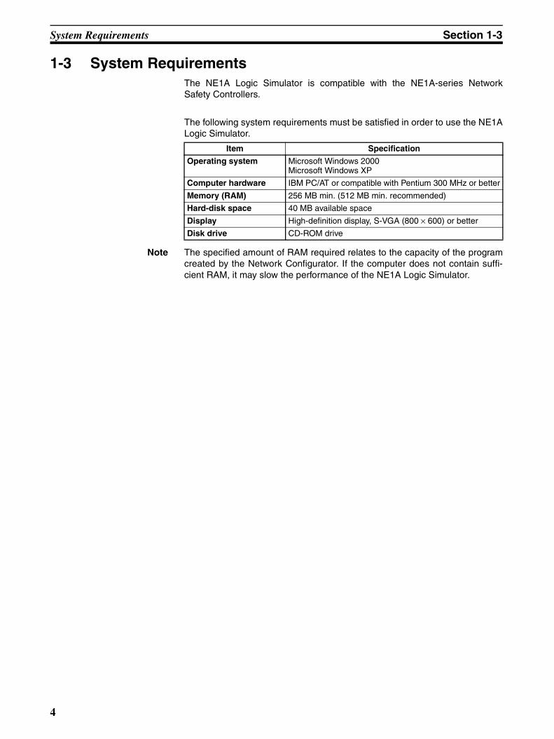
1-3 System RequirementsThe NE1A Logic Simulator is compatible with the NE1A-series NetworkSafety Controllers.
The following system requirements must be satisfied in order to use the NE1ALogic Simulator.
Note The specified amount of RAM required relates to the capacity of the programcreated by the Network Configurator. If the computer does not contain suffi-cient RAM, it may slow the performance of the NE1A Logic Simulator.
Item Specification
Operating system Microsoft Windows 2000Microsoft Windows XP
Computer hardware IBM PC/AT or compatible with Pentium 300 MHz or better
Memory (RAM) 256 MB min. (512 MB min. recommended)
Hard-disk space 40 MB available space
Display High-definition display, S-VGA (800 × 600) or better
Disk drive CD-ROM drive
4

SECTION 2Basic Operation
This section describes the basic operation of the NE1A Logic Simulator.
2-1 Starting and Exiting the Logic Simulator . . . . . . . . . . . . . . . . . . . . . . . . . . . . 6
2-1-1 Starting the Logic Simulator. . . . . . . . . . . . . . . . . . . . . . . . . . . . . . . 6
2-1-2 Exiting the Logic Simulator . . . . . . . . . . . . . . . . . . . . . . . . . . . . . . . 6
2-2 NE1A Logic Simulator Window Configuration . . . . . . . . . . . . . . . . . . . . . . . 7
2-3 Menus . . . . . . . . . . . . . . . . . . . . . . . . . . . . . . . . . . . . . . . . . . . . . . . . . . . . . . . 8
2-4 Pop-up Menus . . . . . . . . . . . . . . . . . . . . . . . . . . . . . . . . . . . . . . . . . . . . . . . . . 10
2-5 Tool Bars . . . . . . . . . . . . . . . . . . . . . . . . . . . . . . . . . . . . . . . . . . . . . . . . . . . . . 11
2-5-1 General Tool Bar. . . . . . . . . . . . . . . . . . . . . . . . . . . . . . . . . . . . . . . . 11
2-5-2 Debug Tool Bar. . . . . . . . . . . . . . . . . . . . . . . . . . . . . . . . . . . . . . . . . 11
2-5-3 Timing Chart Tool Bar . . . . . . . . . . . . . . . . . . . . . . . . . . . . . . . . . . . 12
2-5-4 Watch Tool Bar . . . . . . . . . . . . . . . . . . . . . . . . . . . . . . . . . . . . . . . . . 13
2-6 Status Bar . . . . . . . . . . . . . . . . . . . . . . . . . . . . . . . . . . . . . . . . . . . . . . . . . . . . 14
2-7 Simulation Procedure . . . . . . . . . . . . . . . . . . . . . . . . . . . . . . . . . . . . . . . . . . . 15
2-8 Creating Logic Programs . . . . . . . . . . . . . . . . . . . . . . . . . . . . . . . . . . . . . . . . 16
2-9 Creating Simulation Files . . . . . . . . . . . . . . . . . . . . . . . . . . . . . . . . . . . . . . . . 17
2-10 Opening Simulation Files . . . . . . . . . . . . . . . . . . . . . . . . . . . . . . . . . . . . . . . . 18
2-11 Importing Programs . . . . . . . . . . . . . . . . . . . . . . . . . . . . . . . . . . . . . . . . . . . . 19
2-12 Debugging . . . . . . . . . . . . . . . . . . . . . . . . . . . . . . . . . . . . . . . . . . . . . . . . . . . . 21
2-12-1 Debugging with the Logic Window . . . . . . . . . . . . . . . . . . . . . . . . . 21
2-12-2 Debugging with the Timing Chart Window . . . . . . . . . . . . . . . . . . . 21
2-13 Using the Watch Window . . . . . . . . . . . . . . . . . . . . . . . . . . . . . . . . . . . . . . . . 22
2-13-1 What Is the Watch Window? . . . . . . . . . . . . . . . . . . . . . . . . . . . . . . 22
2-13-2 Displaying/Hiding the Watch Window . . . . . . . . . . . . . . . . . . . . . . . 22
2-13-3 Adding Tags to the Watch Window . . . . . . . . . . . . . . . . . . . . . . . . . 22
2-13-4 Deleting from the Watch Window . . . . . . . . . . . . . . . . . . . . . . . . . . 24
2-13-5 Modifying Tag Values. . . . . . . . . . . . . . . . . . . . . . . . . . . . . . . . . . . . 25
2-13-6 Moving Tags . . . . . . . . . . . . . . . . . . . . . . . . . . . . . . . . . . . . . . . . . . . 25
2-14 Saving Simulation Files . . . . . . . . . . . . . . . . . . . . . . . . . . . . . . . . . . . . . . . . . 26
2-15 Versions . . . . . . . . . . . . . . . . . . . . . . . . . . . . . . . . . . . . . . . . . . . . . . . . . . . . . . 27
2-16 Help Display . . . . . . . . . . . . . . . . . . . . . . . . . . . . . . . . . . . . . . . . . . . . . . . . . . 28
5

Starting and Exiting the Logic Simulator Section 2-1
2-1 Starting and Exiting the Logic SimulatorThis section describes how to start and how to exit the NE1A Logic Simulator.
2-1-1 Starting the Logic SimulatorUse the following procedure to start the NE1A Logic Simulator.
1,2,3... 1. Select Start - All Program - OMRON Network Configurator for De-viceNet Safety - NE1A Logic Simulator.
The NE1A Logic Simulator will start and the following main window will bedisplayed.
2-1-2 Exiting the Logic SimulatorUse the following procedure to exit the NE1A Logic Simulator.
1,2,3... 1. Select File - Exit from the main window.
The NE1A Logic Simulator will be closed.
6
NE1A Logic Simulator Window Configuration Section 2-2
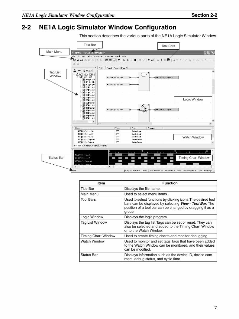
2-2 NE1A Logic Simulator Window ConfigurationThis section describes the various parts of the NE1A Logic Simulator Window.
Logic Window
Title Bar
Main Menu
Tool Bars
Watch Window
Timing Chart Window
Tag List Window
Status Bar
Item Function
Title Bar Displays the file name.
Main Menu Used to select menu items.
Tool Bars Used to select functions by clicking icons.The desired tool bars can be displayed by selecting View - Tool Bar. The position of a tool bar can be changed by dragging it as a group.
Logic Window Displays the logic program.
Tag List Window Displays the tag list.Tags can be set or reset. They can also be selected and added to the Timing Chart Window or to the Watch Window.
Timing Chart Window Used to create timing charts and monitor debugging.
Watch Window Used to monitor and set tags.Tags that have been added to the Watch Window can be monitored, and their values can be modified.
Status Bar Displays information such as the device ID, device com-ment, debug status, and cycle time.
7

Menus Section 2-3
2-3 MenusMenu items and shortcut keys for the NE1A Logic Simulator are listed in thefollowing table.
Main menu Item Shortcut key Function
File Open Ctrl+O Opens an existing file.
Save Ctrl+S Overwrites the current working file.
Save As Saves the current working file with a new name.
Import Program Reads in program data from a file.
Import Timing Chart Data
Reads in timing chart data from a file.
Export Timing Chart Data
Writes timing chart data to a file.
Print Timing Chart Ctrl+P Prints the timing chart.
Recent Displays recently used files.
Exit Closes the application and saves the file.
Edit Copy Ctrl+C Copies the selected area of the timing chart and saves it to the clipboard.
Paste Ctrl+V Pastes the contents of the clipboard onto the timing chart.
Delete Del Deletes the selected tags in the Timing Chart Window or Watch Window.
View Tool Bars Displays/Hides the tool bars.
Windows Displays/Hides windows.
Status Bar Displays/Hides the status bar.
Next Pane F6 Switches to the next pane.
Previous Pane Shift+F6 Switches to the previous pane.
Zoom In Enlarges the display in the Logic Window or the Timing Chart Window.
Zoom Out Reduces the display in the Logic Window or the Timing Chart Window.
Debug Start F5 Starts debugging in the Logic Window.
Execute 1 Cycle F10 Executes the logic program for one cycle.
Pause Ctrl+F5 Pauses the logic program.
Stop Shift+F5 Stops and resets the logic program.
Set Ctrl+J Turns ON the selected tags.
Reset Ctrl+K Turns OFF the selected tags.
Reverse Ctrl+R Reverses the selected tags.
Input Pulse Applies a specified pulse input to the selected tag.
Set Initial Values Sets the initial values of tags.
Feedback Settings Makes feedback settings.
Set Cycle Time Base Value
Sets the cycle time base value for executing the logic pro-gram.
Monitor Function Block
Used to monitor user-defined function blocks.
8

Menus Section 2-3
Timing Chart Execute F7 Executes timing chart simulation.
Execute 1 Pulse F8 Executes timing chart simulation for one pulse.
Pause Ctrl+F7 Pauses timing chart simulation.
Stop Shift+F7 Stops and resets timing chart simulation.
Add Tag Insert Adds tags from the tag list to the Timing Chart Window.
ON S Turns ON the selected section of the waveform in the timing chart.
OFF R Turns OFF the selected section of the waveform in the timing chart.
Reverse Space Reverses the selected section of the waveform in the timing chart.
Make Pulses Applies the specified pulses to the selected section of the tim-ing chart.
Move Up Moves the selected tags in the timing chart upwards.
Move Down Moves the selected tags in the timing chart downwards.
Options Sets the timing chart options.
Breakpoints Register/Unregister F9 Registers/Unregisters a breakpoint at a specified position in the timing chart.
Delete All Shift+F9 Deletes all breakpoints in the timing chart.
Enable Enables the selected breakpoint.
Disable Disables the selected breakpoint.
Display Breakpoint List
Displays a list of breakpoints.
I/O Breakpoint Sets an I/O breakpoint.
Watch Add Tag Ctrl+Insert Adds tags to the Watch Window.
Move Up Moves the selected tags upwards.
Move Down Moves the selected tags downwards.
Help Topics F1 Displays the help file.
About Displays NE1A Logic Simulator version information.
Main menu Item Shortcut key Function
9
Pop-up Menus Section 2-4
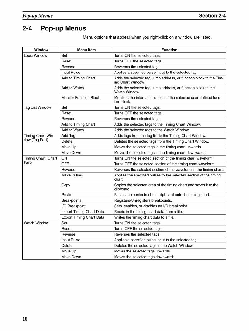
2-4 Pop-up MenusMenu options that appear when you right-click on a window are listed.
Window Menu item Function
Logic Window Set Turns ON the selected tags.
Reset Turns OFF the selected tags.
Reverse Reverses the selected tags.
Input Pulse Applies a specified pulse input to the selected tag.
Add to Timing Chart Adds the selected tag, jump address, or function block to the Tim-ing Chart Window.
Add to Watch Adds the selected tag, jump address, or function block to the Watch Window.
Monitor Function Block Monitors the internal functions of the selected user-defined func-tion block.
Tag List Window Set Turns ON the selected tags.
Reset Turns OFF the selected tags.
Reverse Reverses the selected tags.
Add to Timing Chart Adds the selected tags to the Timing Chart Window.
Add to Watch Adds the selected tags to the Watch Window.
Timing Chart Win-dow (Tag Part)
Add Tag Adds tags from the tag list to the Timing Chart Window.
Delete Deletes the selected tags from the Timing Chart Window.
Move Up Moves the selected tags in the timing chart upwards.
Move Down Moves the selected tags in the timing chart downwards.
Timing Chart (Chart Part)
ON Turns ON the selected section of the timing chart waveform.
OFF Turns OFF the selected section of the timing chart waveform.
Reverse Reverses the selected section of the waveform in the timing chart.
Make Pulses Applies the specified pulses to the selected section of the timing chart.
Copy Copies the selected area of the timing chart and saves it to the clipboard.
Paste Pastes the contents of the clipboard onto the timing chart.
Breakpoints Registers/Unregisters breakpoints.
I/O Breakpoint Sets, enables, or disables an I/O breakpoint.
Import Timing Chart Data Reads in the timing chart data from a file.
Export Timing Chart Data Writes the timing chart data to a file.
Watch Window Set Turns ON the selected tags.
Reset Turns OFF the selected tags.
Reverse Reverses the selected tags.
Input Pulse Applies a specified pulse input to the selected tag.
Delete Deletes the selected tags in the Watch Window.
Move Up Moves the selected tags upwards.
Move Down Moves the selected tags downwards.
10

Tool Bars Section 2-5
2-5 Tool BarsThis section describes the functions of the tool bars in the NE1A Logic Simu-lator.
There are four tool bars in the NE1A Logic Simulator as described below.Each tool bar can be displayed or hidden by selecting View - Tool Bars fol-lowed by the name of the tool bar.
2-5-1 General Tool Bar
2-5-2 Debug Tool Bar
Icon Function Description
Open File Opens an existing file.
Save File Overwrites the current working file.
Print Timing Chart Prints the timing chart.
Copy Copies the selected area of the timing chart and saves it to the clipboard.
Paste Pastes the contents of the clipboard onto the timing chart.
Delete Tag Deletes tags in the Timing Chart Window or Watch Window.
Zoom In Enlarges the display on the Logic Window or the Timing Chart Window.
Zoom Out Reduces the display on the Logic Window or the Timing Chart Window.
Tag List Window Displays/Hides the Tag List Window.
Timing Chart Window Displays/Hides the Timing Chart Window.
Watch Window Displays/Hides the Watch Window.
Topics Displays the help file.
Icon Function Description
Start Starts debugging in the Logic Window.
Execute 1 Cycle Executes the logic program for one cycle.
Pause Pauses the logic program.
Stop Stops and resets the logic program.
Set Turns ON the selected tags.
Reset Turns OFF the selected tags.
11

Tool Bars Section 2-5
2-5-3 Timing Chart Tool Bar
Feedback Settings Makes feedback settings.
Set Initial Values Sets the initial values of input tags.
Icon Function Description
Icon Function Description
Start Executes timing chart simulation.
Execute 1 Pulse Executes timing chart simulation for one pulse
Pause Pauses timing chart simulation.
Stop Stops and resets timing chart simulation.
Add Tag Adds tags from the tag list to the Timing Chart Window.
Move Up Moves the selected tags in the timing chart upwards.
Move Down Moves the selected tags in the timing chart downwards.
ON Turns ON the selected section of the wave-form in the timing chart.
OFF Turns OFF the selected section of the wave-form in the timing chart.
Reverse Reverses the selected section of the wave-form in the timing chart.
Make Pulses Applies the specified pulses to the selected section of the timing chart.
Register/Unregister Registers/Unregisters a breakpoint at a specified position in the timing chart.
Delete All Deletes all breakpoints in the timing chart.
Enable Enables the selected breakpoint.
Disable Disables the selected breakpoints.
Display Breakpoint List Displays a list of the breakpoints.
I/O Breakpoint Sets an I/O breakpoint.
Enable Enables the I/O breakpoint.
Disable Disables the I/O breakpoint.
12

Tool Bars Section 2-5
2-5-4 Watch Tool Bar
Icon Function Description
Move Up Moves the selected tags in the Watch Win-dow upwards.
Move Down Moves the selected tags in the Watch Win-dow downwards.
13
Status Bar Section 2-6
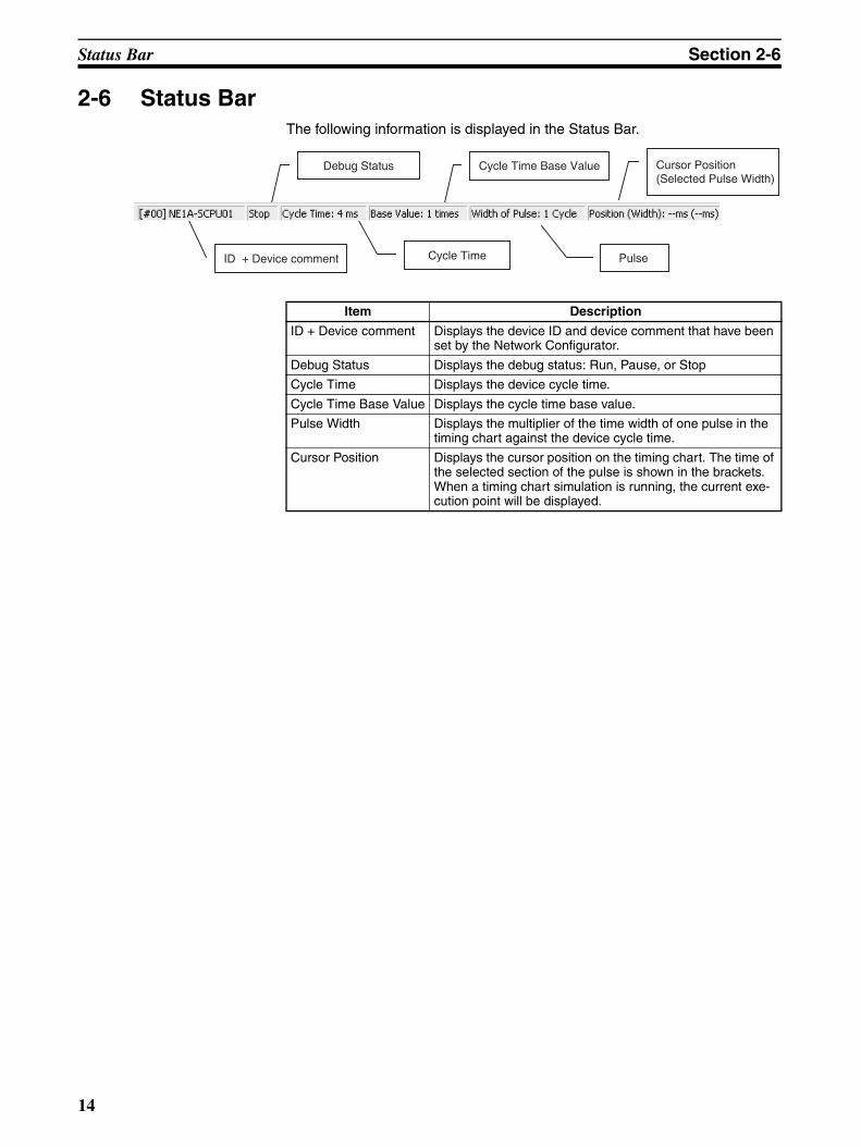
2-6 Status BarThe following information is displayed in the Status Bar.
Cycle Time
Debug Status
ID + Device comment
Cycle Time Base Value
Pulse
Cursor Position (Selected Pulse Width)
Item Description
ID + Device comment Displays the device ID and device comment that have been set by the Network Configurator.
Debug Status Displays the debug status: Run, Pause, or Stop
Cycle Time Displays the device cycle time.
Cycle Time Base Value Displays the cycle time base value.
Pulse Width Displays the multiplier of the time width of one pulse in the timing chart against the device cycle time.
Cursor Position Displays the cursor position on the timing chart. The time of the selected section of the pulse is shown in the brackets. When a timing chart simulation is running, the current exe-cution point will be displayed.
14

Simulation Procedure Section 2-7
2-7 Simulation ProcedureUse the following procedure to simulate execution of a safety logic program.
Create a logic program using the logic editor in the Network Configurator.
Open the simulation file (.smr) in the NE1A Logic Simulator or import the program.
Create a simulation file (.smr) using the Network Configurator.
Execute the simulation in the NE1A Logic Simulator.
1. Create a Logic Program
3. Read in the File
2. Create a Simulation File
4. Execute the Simulation
….Refer to 2-9 Creating Simulation Files.
….Refer to 2-10 Opening Simulation Files or 2-11 Importing Programs.
….Refer to SECTION 3 Debugging with the Logic Window and SECTION 4 Debugging with theTiming Chart Window.
….Refer to DeviceNet Safety System Configuration Manual (Cat. No. Z905).
15

Creating Logic Programs Section 2-8
2-8 Creating Logic ProgramsLogic Programs must be created with the Network Configurator.
For information on creating logic programs using the Network Configurator,refer to Section 6 Programming the Safety Network Controller in theDeviceNet Safety System Configuration Manual (Cat. No. Z905).
16
Creating Simulation Files Section 2-9
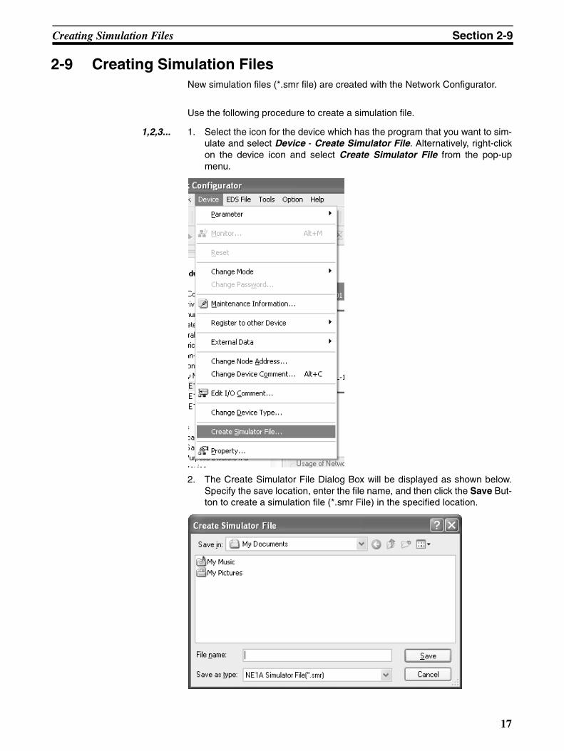
2-9 Creating Simulation FilesNew simulation files (*.smr file) are created with the Network Configurator.
Use the following procedure to create a simulation file.
1,2,3... 1. Select the icon for the device which has the program that you want to sim-ulate and select Device - Create Simulator File. Alternatively, right-clickon the device icon and select Create Simulator File from the pop-upmenu.
2. The Create Simulator File Dialog Box will be displayed as shown below.Specify the save location, enter the file name, and then click the Save But-ton to create a simulation file (*.smr File) in the specified location.
17
Opening Simulation Files Section 2-10
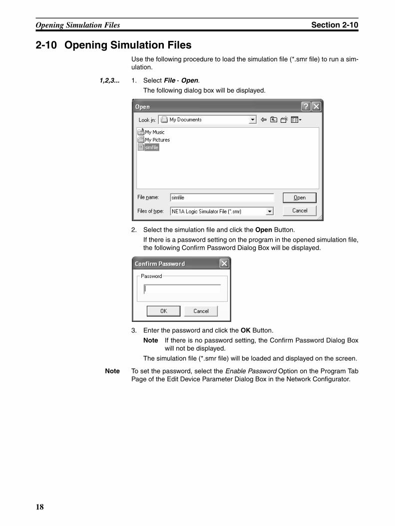
2-10 Opening Simulation FilesUse the following procedure to load the simulation file (*.smr file) to run a sim-ulation.
1,2,3... 1. Select File - Open.
The following dialog box will be displayed.
2. Select the simulation file and click the Open Button.
If there is a password setting on the program in the opened simulation file,the following Confirm Password Dialog Box will be displayed.
3. Enter the password and click the OK Button.
Note If there is no password setting, the Confirm Password Dialog Boxwill not be displayed.
The simulation file (*.smr file) will be loaded and displayed on the screen.
Note To set the password, select the Enable Password Option on the Program TabPage of the Edit Device Parameter Dialog Box in the Network Configurator.
18

Importing Programs Section 2-11
2-11 Importing ProgramsTo load programs from other simulation files, use the program import function.The program import function only loads the program part of the file; informa-tion in the Timing Chart Window and Watch Window will not be changed.
1,2,3... 1. Select File - Import Program.
The following dialog box will be displayed.
2. Select a Simulation File and click the Open Button.
If there is a password setting on the program in the imported simulation file,the following Confirm Password Dialog Box will be displayed.
3. Enter the Password and click the OK button.
Note If there is no password setting, the Confirm Password Dialog Boxwill not be displayed.
The program part of the simulation file will be loaded and the logic programwill be displayed on the screen.
Note (1) After importing the program, if the tags and function blocks used in theTiming Chart Window and Watch Window are not used within the import-ed program, their names will appears as “???”. Check these tags to seeif they are required. If they are not required, delete them. The originalnames can be displayed again by importing the original program.
(2) To correct a program from a file that is being used in a simulation, edit theprogram with the Network Configurator and then create a new simulationfile. Save the new file with a different name to that of the file being usedin the simulation, then import the program from that file. Files can be over-written while the Logic Simulator is being used but any data other thanthe program (i.e., information on the Timing Chart Window and WatchWindow) will all be deleted.
19

Importing Programs Section 2-11
(3) To set the password, select the Enable Password Option on the ProgramTab Page of the Edit Device Parameter Dialog Box in the Network Con-figurator.
20
Debugging Section 2-12
2-12 DebuggingThere are the following two methods for debugging using the NE1A LogicSimulator.
2-12-1 Debugging with the Logic Window The Logic Window displays the logic program. It is the similar to the OnlineMonitor of the logic editor in the Network Configurator. Input tags can be mod-ified using the Logic Window, Tag List Window, or Watch Window. The corre-sponding outputs can then be verified. A graphical interface allows for easy-to-understand verification, and is suited for verifying simple logic.
Refer to SECTION 3 Debugging with the Logic Window for details.
2-12-2 Debugging with the Timing Chart WindowThe user can enter input tag values over time and execute a simulation forthem. By executing the simulation, an output result timing chart can beobtained that is suited for debugging when the input values change in shortperiods of time.
Refer to SECTION 4 Debugging with the Timing Chart Window for details.
21
Using the Watch Window Section 2-13
2-13 Using the Watch WindowThis section describes how to use the Watch Window.
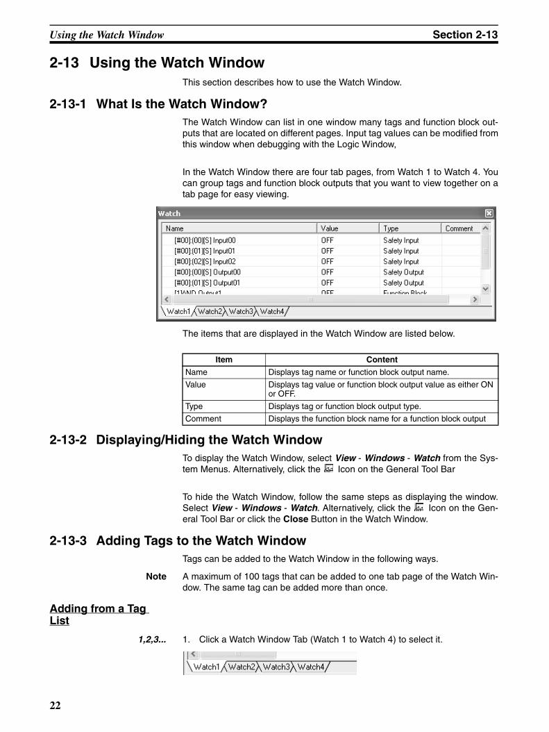
2-13-1 What Is the Watch Window?The Watch Window can list in one window many tags and function block out-puts that are located on different pages. Input tag values can be modified fromthis window when debugging with the Logic Window,
In the Watch Window there are four tab pages, from Watch 1 to Watch 4. Youcan group tags and function block outputs that you want to view together on atab page for easy viewing.
The items that are displayed in the Watch Window are listed below.
2-13-2 Displaying/Hiding the Watch WindowTo display the Watch Window, select View - Windows - Watch from the Sys-tem Menus. Alternatively, click the Icon on the General Tool Bar
To hide the Watch Window, follow the same steps as displaying the window.Select View - Windows - Watch. Alternatively, click the Icon on the Gen-eral Tool Bar or click the Close Button in the Watch Window.
2-13-3 Adding Tags to the Watch WindowTags can be added to the Watch Window in the following ways.
Note A maximum of 100 tags that can be added to one tab page of the Watch Win-dow. The same tag can be added more than once.
Adding from a Tag List
1,2,3... 1. Click a Watch Window Tab (Watch 1 to Watch 4) to select it.
Item Content
Name Displays tag name or function block output name.
Value Displays tag value or function block output value as either ON or OFF.
Type Displays tag or function block output type.
Comment Displays the function block name for a function block output
22
Using the Watch Window Section 2-13
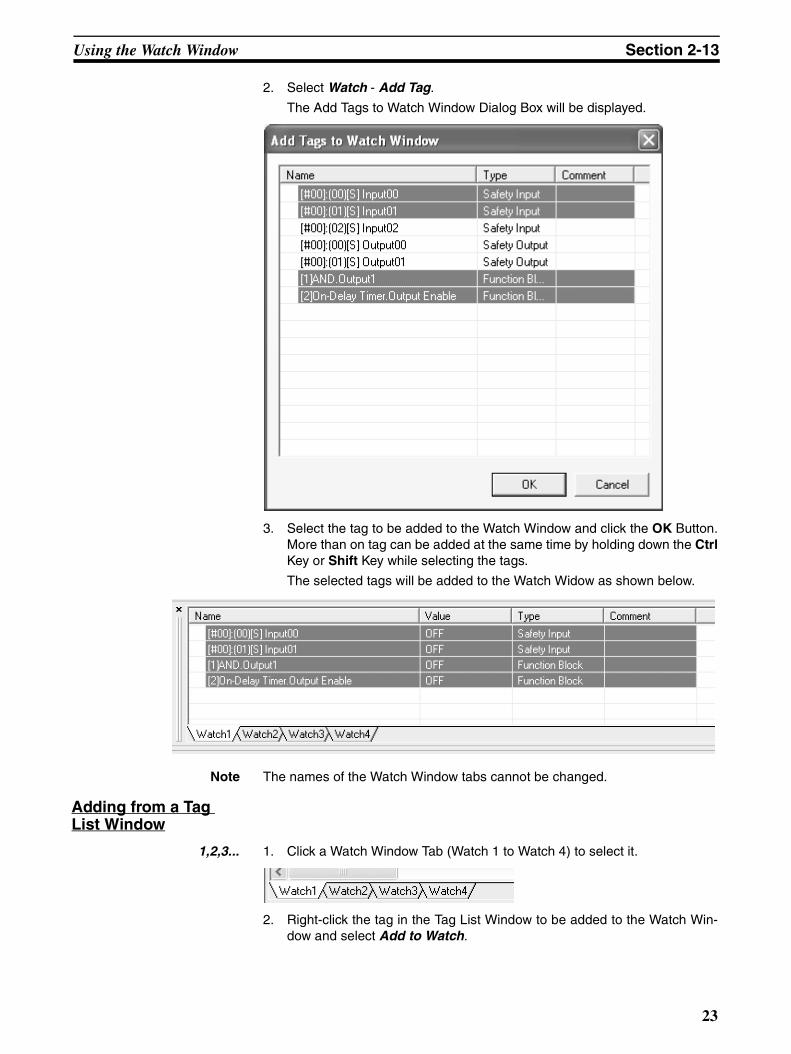
2. Select Watch - Add Tag.
The Add Tags to Watch Window Dialog Box will be displayed.
3. Select the tag to be added to the Watch Window and click the OK Button.More than on tag can be added at the same time by holding down the CtrlKey or Shift Key while selecting the tags.
The selected tags will be added to the Watch Widow as shown below.
Note The names of the Watch Window tabs cannot be changed.
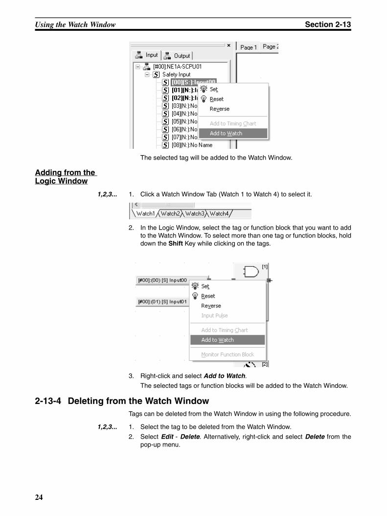
Adding from a Tag List Window
1,2,3... 1. Click a Watch Window Tab (Watch 1 to Watch 4) to select it.
2. Right-click the tag in the Tag List Window to be added to the Watch Win-dow and select Add to Watch.
23
Using the Watch Window Section 2-13
The selected tag will be added to the Watch Window.
Adding from the Logic Window
1,2,3... 1. Click a Watch Window Tab (Watch 1 to Watch 4) to select it.
2. In the Logic Window, select the tag or function block that you want to addto the Watch Window. To select more than one tag or function blocks, holddown the Shift Key while clicking on the tags.
3. Right-click and select Add to Watch.
The selected tags or function blocks will be added to the Watch Window.
2-13-4 Deleting from the Watch WindowTags can be deleted from the Watch Window in using the following procedure.
1,2,3... 1. Select the tag to be deleted from the Watch Window.
2. Select Edit - Delete. Alternatively, right-click and select Delete from thepop-up menu.
24
Using the Watch Window Section 2-13
2-13-5 Modifying Tag ValuesWhen the Logic Window is used for debugging, input tags that have beenadded to the Watch Window can be set, reset, or reversed.
Note Output tag values or function block output values cannot be modified.
1,2,3... 1. Select a tag from the Watch Window to modify its value. More than one tagcan be selected by holding down the Ctrl Key or the Shift Key while select-ing the tags.
2. Select Debug and then Set, Reset, or Reverse. Alternatively, right-clickand select Set, Reset, or Reverse from the pop-up menu.
2-13-6 Moving TagsTags that have been added to the Watch Window can be moved up or down.
1,2,3... 1. Select a tag to be moved from the Watch Window. More than one tag canbe selected by pressing the Ctrl Key or the Shift Key while selecting tags.
2. Select Watch - Move Up (or Move Down). Alternatively, right-click and se-lect Move Up (or Move Down) from the pop-up menu.
25
Saving Simulation Files Section 2-14
2-14 Saving Simulation FilesYou can save a simulation file (*.smr) by overwriting an existing file or as anew file with a different name. Saving a file will save the logic program, timingchart data, and registered watch data in a single file.
Overwriting Simulation Files
1,2,3... 1. Select File - Save.
The simulation file will be overwritten.
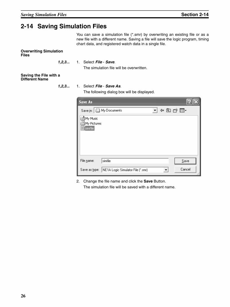
Saving the File with a Different Name
1,2,3... 1. Select File - Save As.
The following dialog box will be displayed.
2. Change the file name and click the Save Button.
The simulation file will be saved with a different name.
26
Versions Section 2-15
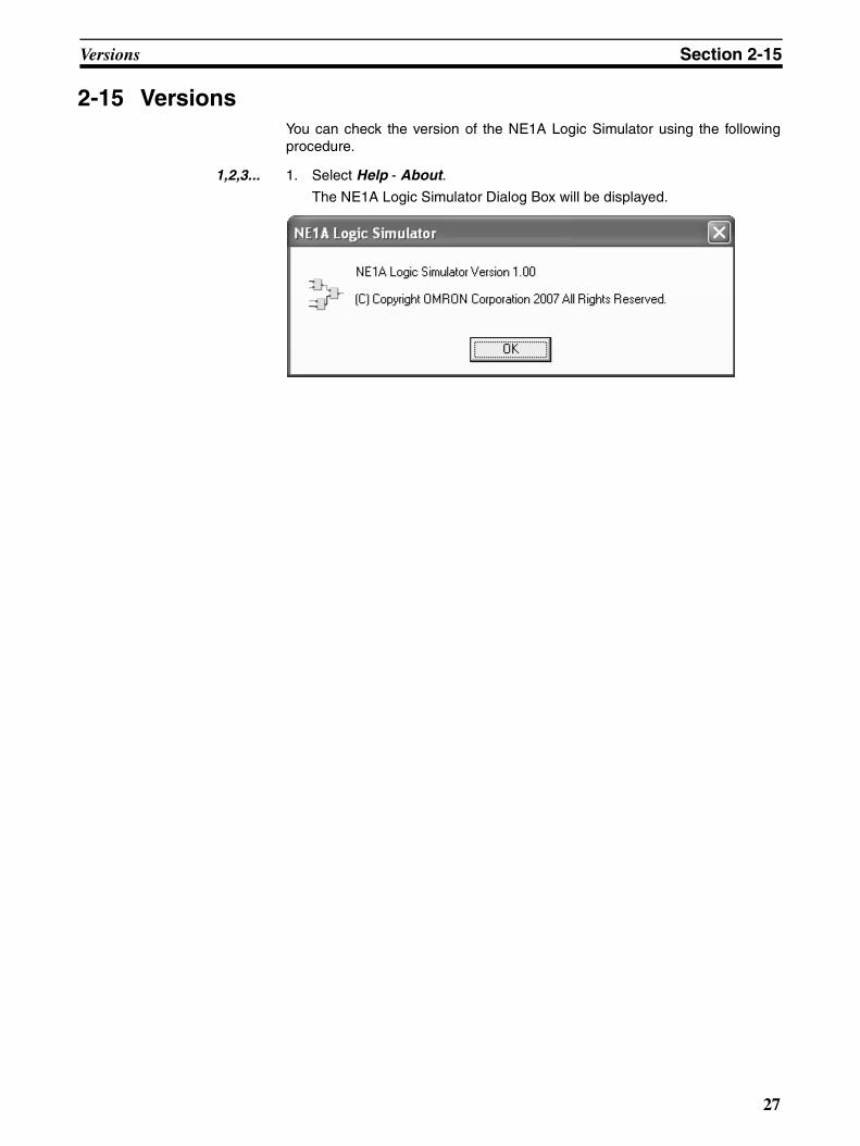
2-15 VersionsYou can check the version of the NE1A Logic Simulator using the followingprocedure.
1,2,3... 1. Select Help - About.
The NE1A Logic Simulator Dialog Box will be displayed.
27
Help Display Section 2-16
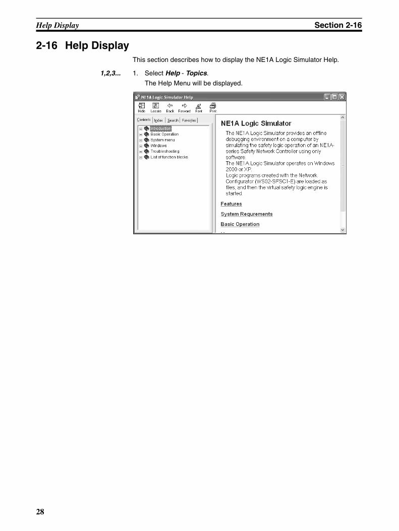
2-16 Help DisplayThis section describes how to display the NE1A Logic Simulator Help.
1,2,3... 1. Select Help - Topics.
The Help Menu will be displayed.
28
SECTION 3Debugging with the Logic Window
This section describes how to debug programs for the NE1A Logic Simulator using the Logic Window.
3-1 Overview . . . . . . . . . . . . . . . . . . . . . . . . . . . . . . . . . . . . . . . . . . . . . . . . . . . . . 30
3-2 Starting and Stopping the Logic Program. . . . . . . . . . . . . . . . . . . . . . . . . . . . 31
3-2-1 Starting . . . . . . . . . . . . . . . . . . . . . . . . . . . . . . . . . . . . . . . . . . . . . . . 31
3-2-2 Stopping . . . . . . . . . . . . . . . . . . . . . . . . . . . . . . . . . . . . . . . . . . . . . . 31
3-2-3 Pausing . . . . . . . . . . . . . . . . . . . . . . . . . . . . . . . . . . . . . . . . . . . . . . . 31
3-2-4 Executing One Cycle . . . . . . . . . . . . . . . . . . . . . . . . . . . . . . . . . . . . 31
3-3 Modifying Input Tags . . . . . . . . . . . . . . . . . . . . . . . . . . . . . . . . . . . . . . . . . . . 32
3-3-1 Setting, Resetting, and Reversing . . . . . . . . . . . . . . . . . . . . . . . . . . . 32
3-3-2 Inputting Pulses . . . . . . . . . . . . . . . . . . . . . . . . . . . . . . . . . . . . . . . . 32
3-4 Setting Initial Values . . . . . . . . . . . . . . . . . . . . . . . . . . . . . . . . . . . . . . . . . . . . 34
3-5 Setting the Cycle Time Base Value . . . . . . . . . . . . . . . . . . . . . . . . . . . . . . . . . 35
3-6 Feedback Settings . . . . . . . . . . . . . . . . . . . . . . . . . . . . . . . . . . . . . . . . . . . . . . 36
3-7 Monitoring a User-defined Function Block . . . . . . . . . . . . . . . . . . . . . . . . . . 38
3-8 Zooming In and Out of the Logic Window Display . . . . . . . . . . . . . . . . . . . . 39
29
Overview Section 3-1
3-1 OverviewThis section describes how to debug using the Logic Window.
The Logic Window displays the Logic Program. Input tags can be modifiedusing the Logic Window, Tag List Window, or the Watch Window. The corre-sponding outputs can then be verified. Similar to the Online Monitor Screenfor the Logic Editor of the Network Configurator, tags that are ON and linesthat are connected are displayed in dark green.
Note The Timing Chart Window and the Logic Window cannot be used for debug-ging simultaneously.
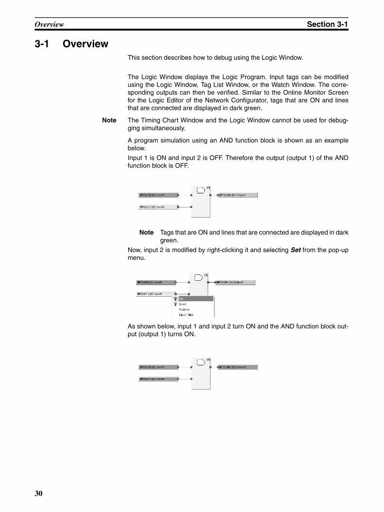
A program simulation using an AND function block is shown as an examplebelow.
Input 1 is ON and input 2 is OFF. Therefore the output (output 1) of the ANDfunction block is OFF.
Note Tags that are ON and lines that are connected are displayed in darkgreen.
Now, input 2 is modified by right-clicking it and selecting Set from the pop-upmenu.
As shown below, input 1 and input 2 turn ON and the AND function block out-put (output 1) turns ON.
30

Starting and Stopping the Logic Program Section 3-2
3-2 Starting and Stopping the Logic ProgramThis section describes how to start and stop a logic program.
3-2-1 StartingTo start a logic program when it is stopped or paused, select Debug - Start.Alternatively, click the Icon on the tool bar.
The logic program will begin execution. Input tags can be modified and thecorresponding outputs verified while in this state.
3-2-2 StoppingTo stop a logic program when it is being executed or when it is paused, selectDebug - Stop. Alternatively, click the Icon on the tool bar.
The logic program will stop. When the program is stopped, it will be reset andall input and output tags will return to their initial values.
3-2-3 PausingTo pause execution of a logic program while it is being executed, selectDebug - Pause. Alternatively, click the Icon on the tool bar.
Execution of the logic program will pause.
3-2-4 Executing One Cycle To execute one cycle of the logic program when it is stopped or paused, selectDebug - 1 Cycle Execute. Alternatively, click the Icon on the tool bar.
The logic program will be executed for one cycle and then pause.
31
Modifying Input Tags Section 3-3
3-3 Modifying Input TagsThis section describes how to modify input tags.
3-3-1 Setting, Resetting, and ReversingSet, reset, and reverse functions can be applied in the Logic Window, Tag ListWindow, or Watch Window. Set turns ON a value, Reset turns OFF a value,and Reverse turns OFF a value if it's ON and turns ON a value if it's OFF.
Modifying Tags from the Logic Window
Select an input tag in the Logic Window and select Set, Reset, or Reversefrom the Debug Menu. These functions can be applied also by right-clickingand selecting menu items from the pop-up menu or selecting icons from thetool bar.
More than one tag can be selected and modified at once. To select more thanone tag, hold down the Shift Key while selecting tags with the mouse in theLogic Window, or make a block selection by dragging the mouse.
Modifying Tags from the Tag List Window
Select an input tag in the Tag List Window and select Set, Reset, or Reversefrom the Debug Menu. These functions can be applied also by right-clickingand selecting a menu item from the pop-up menu or selecting icons from thetool bar. More than one tag can be selected and applied at once. To selectmore than one tag, hold down the Shift Key while selecting tags with themouse in the Tag List Window.
Modifying Tags from the Watch Window
Select an input tag in the Watch Window and select Set, Reset, or Reversefrom the Debug Menu. These functions can be applied also by right-clickingand selecting a menu item from the pop-up menu or selecting icons from thetool bar. More than one tag can be selected and applied at once. To selectmore than one tag, hold down the Ctrl Key or Shift Key while selecting tagswith the mouse from the Watch Window.
Note Tags that have been selected in a window can be set or reset by clicking theSet ( ) or Reset ( ) Icon in the Debug Tool Bar.
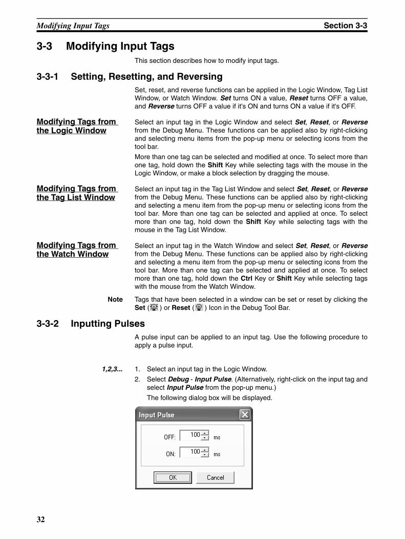
3-3-2 Inputting PulsesA pulse input can be applied to an input tag. Use the following procedure toapply a pulse input.
1,2,3... 1. Select an input tag in the Logic Window.
2. Select Debug - Input Pulse. (Alternatively, right-click on the input tag andselect Input Pulse from the pop-up menu.)
The following dialog box will be displayed.
32

Modifying Input Tags Section 3-3
3. Enter the OFF and ON times and click the OK Button. The time settings forboth the OFF and ON times must be between 100 and 10,000 ms. Thetime setting specified here is the program time. Simulation with the LogicSimulator will be executed based on the time set here, multiplied by the cy-cle time base value.
The shape of the input pulse is shown below.
Click the OK
OFF time
OFF
ON
ON time
Present value
33
Setting Initial Values Section 3-4
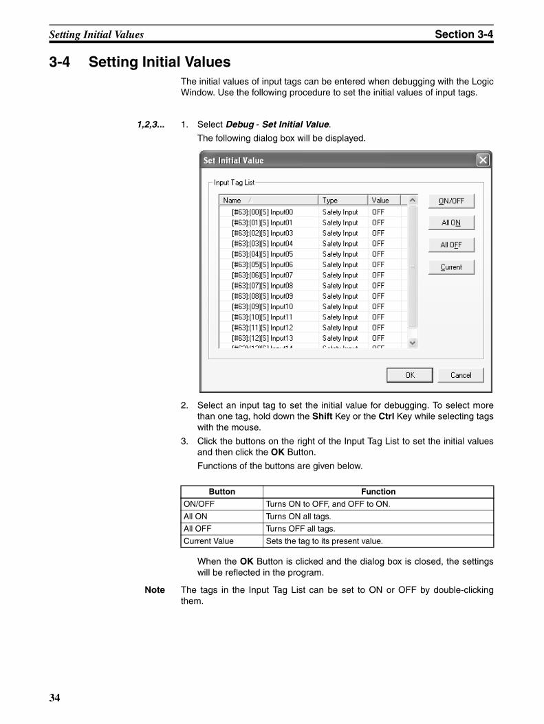
3-4 Setting Initial ValuesThe initial values of input tags can be entered when debugging with the LogicWindow. Use the following procedure to set the initial values of input tags.
1,2,3... 1. Select Debug - Set Initial Value.
The following dialog box will be displayed.
2. Select an input tag to set the initial value for debugging. To select morethan one tag, hold down the Shift Key or the Ctrl Key while selecting tagswith the mouse.
3. Click the buttons on the right of the Input Tag List to set the initial valuesand then click the OK Button.
Functions of the buttons are given below.
When the OK Button is clicked and the dialog box is closed, the settingswill be reflected in the program.
Note The tags in the Input Tag List can be set to ON or OFF by double-clickingthem.
Button Function
ON/OFF Turns ON to OFF, and OFF to ON.
All ON Turns ON all tags.
All OFF Turns OFF all tags.
Current Value Sets the tag to its present value.
34
Setting the Cycle Time Base Value Section 3-5
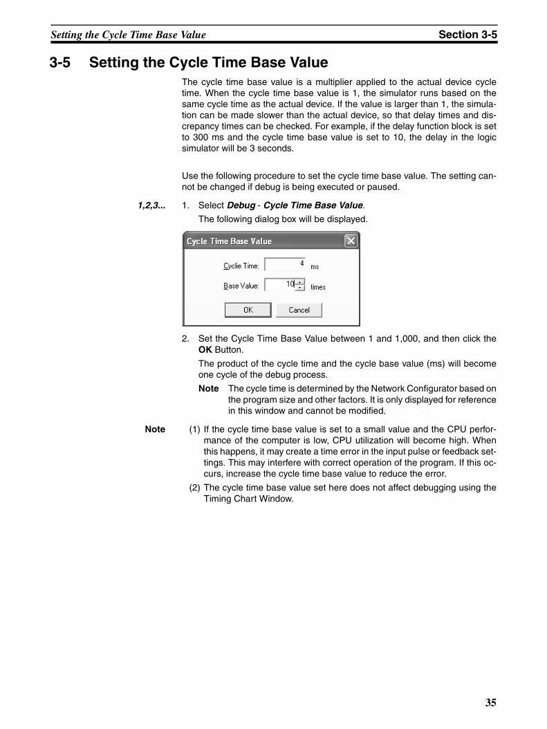
3-5 Setting the Cycle Time Base ValueThe cycle time base value is a multiplier applied to the actual device cycletime. When the cycle time base value is 1, the simulator runs based on thesame cycle time as the actual device. If the value is larger than 1, the simula-tion can be made slower than the actual device, so that delay times and dis-crepancy times can be checked. For example, if the delay function block is setto 300 ms and the cycle time base value is set to 10, the delay in the logicsimulator will be 3 seconds.
Use the following procedure to set the cycle time base value. The setting can-not be changed if debug is being executed or paused.
1,2,3... 1. Select Debug - Cycle Time Base Value.
The following dialog box will be displayed.
2. Set the Cycle Time Base Value between 1 and 1,000, and then click theOK Button.
The product of the cycle time and the cycle base value (ms) will becomeone cycle of the debug process.
Note The cycle time is determined by the Network Configurator based onthe program size and other factors. It is only displayed for referencein this window and cannot be modified.
Note (1) If the cycle time base value is set to a small value and the CPU perfor-mance of the computer is low, CPU utilization will become high. Whenthis happens, it may create a time error in the input pulse or feedback set-tings. This may interfere with correct operation of the program. If this oc-curs, increase the cycle time base value to reduce the error.
(2) The cycle time base value set here does not affect debugging using theTiming Chart Window.
35
Feedback Settings Section 3-6
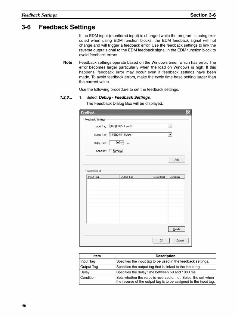
3-6 Feedback SettingsIf the EDM input (monitored input) is changed while the program is being exe-cuted when using EDM function blocks, the EDM feedback signal will notchange and will trigger a feedback error. Use the feedback settings to link thereverse output signal to the EDM feedback signal in the EDM function block toavoid feedback errors.
Note Feedback settings operate based on the Windows timer, which has error. Theerror becomes larger particularly when the load on Windows is high. If thishappens, feedback error may occur even if feedback settings have beenmade. To avoid feedback errors, make the cycle time base setting larger thanthe current value.
Use the following procedure to set the feedback settings.
1,2,3... 1. Select Debug - Feedback Settings.
The Feedback Dialog Box will be displayed.
Item Description
Input Tag Specifies the input tag to be used in the feedback settings.
Output Tag Specifies the output tag that is linked to the input tag.
Delay Specifies the delay time between 50 and 1000 ms.
Condition Sets whether the value is reversed or not. Select the cell when the reverse of the output tag is to be assigned to the input tag.
36
Feedback Settings Section 3-6
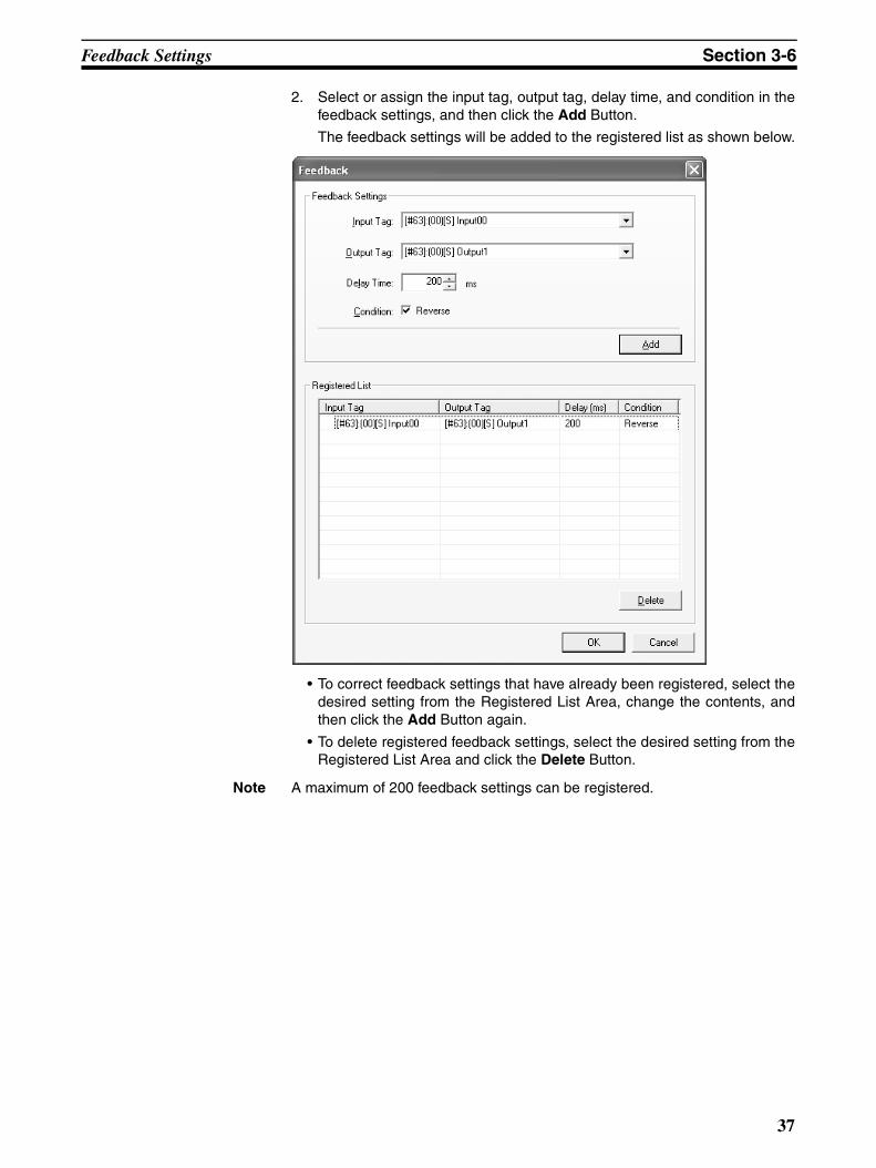
2. Select or assign the input tag, output tag, delay time, and condition in thefeedback settings, and then click the Add Button.
The feedback settings will be added to the registered list as shown below.
• To correct feedback settings that have already been registered, select thedesired setting from the Registered List Area, change the contents, andthen click the Add Button again.
• To delete registered feedback settings, select the desired setting from theRegistered List Area and click the Delete Button.
Note A maximum of 200 feedback settings can be registered.
37

Monitoring a User-defined Function Block Section 3-7
3-7 Monitoring a User-defined Function BlockThis section describes how to monitor the contents of a user-defined functionblock.
1,2,3... 1. Right-click a user-defined function block in the Logic Window and selectMonitor Function Block from the pop-up menu.
The User-defined Function Block Window will be opened as shown below.The contents of the selected user-defined function block will be displayed.
The User-defined Function Block Window has the following functions.
Note (1) Input tags cannot be modified directly from the User-defined FunctionBlock Window. Go to the Logic Window, Tag List Window, or the WatchWindow to modify them.
(2) If the user-defined function block file does not exist, it cannot be moni-tored. Import the function block using the logic editor in the Network Con-figurator.
Main menu Menu item Function
File Exit Exits the user-defined function block monitor and closes the window.
View Tool Bar Displays/hides the tool bar.
Zoom In Enlarges the display.
Zoom Out Reduces the display.
38
Zooming In and Out of the Logic Window Display Section 3-8
3-8 Zooming In and Out of the Logic Window DisplayUse the following procedure to zoom in and out of the display in the LogicWindow.
1,2,3... 1. Click in the Logic Window (or press F6/Shift + F6) to move to the LogicWindow.
2. Select View - Zoom In or View - Zoom Out.
This will zoom in or out of the display in the Logic Window.
This function can only be used in the Logic Window.
Note Pressing the Ctrl Key while moving the mouse wheel up or down will alsozoom in and out of the display in the Logic Window.
39

Zooming In and Out of the Logic Window Display Section 3-8
40

SECTION 4Debugging with the Timing Chart Window
This section describes how to debug programs for the NE1A Logic Simulator using the Timing Chart Window.
4-1 Overview . . . . . . . . . . . . . . . . . . . . . . . . . . . . . . . . . . . . . . . . . . . . . . . . . . . . . 42
4-2 Timing Chart Window. . . . . . . . . . . . . . . . . . . . . . . . . . . . . . . . . . . . . . . . . . . 43
4-3 Adding to the Timing Chart . . . . . . . . . . . . . . . . . . . . . . . . . . . . . . . . . . . . . . 44
4-3-1 Adding from the Tag List . . . . . . . . . . . . . . . . . . . . . . . . . . . . . . . . . 44
4-3-2 Adding from the Tag List Window . . . . . . . . . . . . . . . . . . . . . . . . . . 44
4-3-3 Adding from the Logic Window. . . . . . . . . . . . . . . . . . . . . . . . . . . . 44
4-4 Inputs to the Timing Chart . . . . . . . . . . . . . . . . . . . . . . . . . . . . . . . . . . . . . . . 45
4-4-1 Basic Input . . . . . . . . . . . . . . . . . . . . . . . . . . . . . . . . . . . . . . . . . . . . 45
4-4-2 Pulse Setting . . . . . . . . . . . . . . . . . . . . . . . . . . . . . . . . . . . . . . . . . . . 45
4-4-3 Copying and Pasting in the Timing Chart. . . . . . . . . . . . . . . . . . . . . 45
4-4-4 Editing the Timing Chart with a Text Editor . . . . . . . . . . . . . . . . . . 46
4-5 Starting and Stopping the Timing Chart . . . . . . . . . . . . . . . . . . . . . . . . . . . . . 47
4-6 Importing/Exporting Timing Chart Data. . . . . . . . . . . . . . . . . . . . . . . . . . . . . 48
4-6-1 Importing Timing Chart Data . . . . . . . . . . . . . . . . . . . . . . . . . . . . . . 48
4-6-2 Exporting Timing Chart Data . . . . . . . . . . . . . . . . . . . . . . . . . . . . . . 48
4-7 Printing the Timing Chart . . . . . . . . . . . . . . . . . . . . . . . . . . . . . . . . . . . . . . . . 50
4-8 Timing Chart Options . . . . . . . . . . . . . . . . . . . . . . . . . . . . . . . . . . . . . . . . . . . 51
4-8-1 Displaying the Timing Chart Options Dialog Box . . . . . . . . . . . . . . 51
4-8-2 Setting Tab Page . . . . . . . . . . . . . . . . . . . . . . . . . . . . . . . . . . . . . . . . 51
4-8-3 View Tab Page . . . . . . . . . . . . . . . . . . . . . . . . . . . . . . . . . . . . . . . . . 52
4-8-4 Print Tab Page. . . . . . . . . . . . . . . . . . . . . . . . . . . . . . . . . . . . . . . . . . 53
4-9 Breakpoints . . . . . . . . . . . . . . . . . . . . . . . . . . . . . . . . . . . . . . . . . . . . . . . . . . . 54
4-9-1 Adding Breakpoints . . . . . . . . . . . . . . . . . . . . . . . . . . . . . . . . . . . . . 54
4-9-2 Deleting Breakpoints . . . . . . . . . . . . . . . . . . . . . . . . . . . . . . . . . . . . 54
4-9-3 Enabling/Disabling Breakpoints. . . . . . . . . . . . . . . . . . . . . . . . . . . . 54
4-9-4 Breakpoint List . . . . . . . . . . . . . . . . . . . . . . . . . . . . . . . . . . . . . . . . . 55
4-10 I/O Breakpoint. . . . . . . . . . . . . . . . . . . . . . . . . . . . . . . . . . . . . . . . . . . . . . . . . 56
4-10-1 I/O Breakpoint Settings . . . . . . . . . . . . . . . . . . . . . . . . . . . . . . . . . . 56
4-10-2 Enabling/Disabling the I/O Breakpoint . . . . . . . . . . . . . . . . . . . . . . 57
4-11 Zooming In and Out of the Timing Chart Display . . . . . . . . . . . . . . . . . . . . . 58
41
Overview Section 4-1
4-1 OverviewThis section describes how to debug a program using the Timing Chart Win-dow.
The debugging process starts with assigning input values to tags in the timingchart, executing the logic program, then displaying the output results.
Pulses can be specified in terms of the device cycle time when using the Tim-ing Chart Window. This makes it possible to run simulations for inputs thatfluctuate quickly, which is not possible when debugging with the logic window.
Note Debugging cannot be performed simultaneously using both the Timing ChartWindow and the Logic Window.
42

Timing Chart Window Section 4-2
4-2 Timing Chart WindowThis section describes the various parts of the Timing Chart Window.
The tags and function block outputs are displayed on the left of the window.The corresponding chart is displayed on the right.
Input Tag, Output Tag, orFunction Block Output
Pulse Scale Cursor
Chart
43
Adding to the Timing Chart Section 4-3
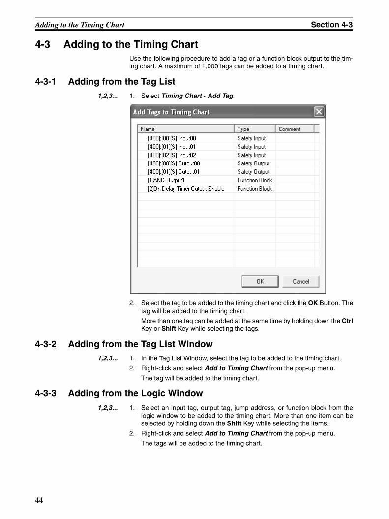
4-3 Adding to the Timing ChartUse the following procedure to add a tag or a function block output to the tim-ing chart. A maximum of 1,000 tags can be added to a timing chart.
4-3-1 Adding from the Tag List1,2,3... 1. Select Timing Chart - Add Tag.
2. Select the tag to be added to the timing chart and click the OK Button. Thetag will be added to the timing chart.
More than one tag can be added at the same time by holding down the CtrlKey or Shift Key while selecting the tags.
4-3-2 Adding from the Tag List Window1,2,3... 1. In the Tag List Window, select the tag to be added to the timing chart.
2. Right-click and select Add to Timing Chart from the pop-up menu.
The tag will be added to the timing chart.
4-3-3 Adding from the Logic Window1,2,3... 1. Select an input tag, output tag, jump address, or function block from the
logic window to be added to the timing chart. More than one item can beselected by holding down the Shift Key while selecting the items.
2. Right-click and select Add to Timing Chart from the pop-up menu.
The tags will be added to the timing chart.
44

Inputs to the Timing Chart Section 4-4
4-4 Inputs to the Timing ChartThis section explains how to apply inputs to the tags that have been added tothe timing chart. The output tags, jump address, and function blocks cannotbe changed.
4-4-1 Basic InputUse the following procedure to turn the input tags to ON or OFF or to reverse the tag status.
1,2,3... 1. Move the cursor to the area where you want to apply an input to the timingchart. An area can be selected.
2. Select ON, OFF, or Reverse from the Timing Chart Menu.
4-4-2 Pulse SettingA specified pulse can be assigned using the following procedure.
1,2,3... 1. Select the area on the timing chart where you want to apply the set pulses.
2. Select Timing Chart - Make Pulses. Alternatively, right-click in the select-ed area and select Make Pulses from the pop-up menu.
The following dialog box will be displayed.
3. Set the number of pulses and the start pulse, and then click the OK Button.
The specified pulses will be applied to the selected area.
4-4-3 Copying and Pasting in the Timing Chart1,2,3... 1. Select the area on the timing chart to be copied.
2. Select Edit - Copy. Alternatively, right-click and select Copy from the pop-up menu.
3. Move the cursor to where you want to paste and select Edit - Paste. Alter-natively, right-click and select Paste from the pop-up menu.
45
Inputs to the Timing Chart Section 4-4
4-4-4 Editing the Timing Chart with a Text EditorThe timing chart can be edited with a text editor by using the copy and pastefunctions.
1,2,3... 1. Select the area of the timing chart that you want to edit.
2. Select Edit - Copy.
The contents will be copied to the clipboard.
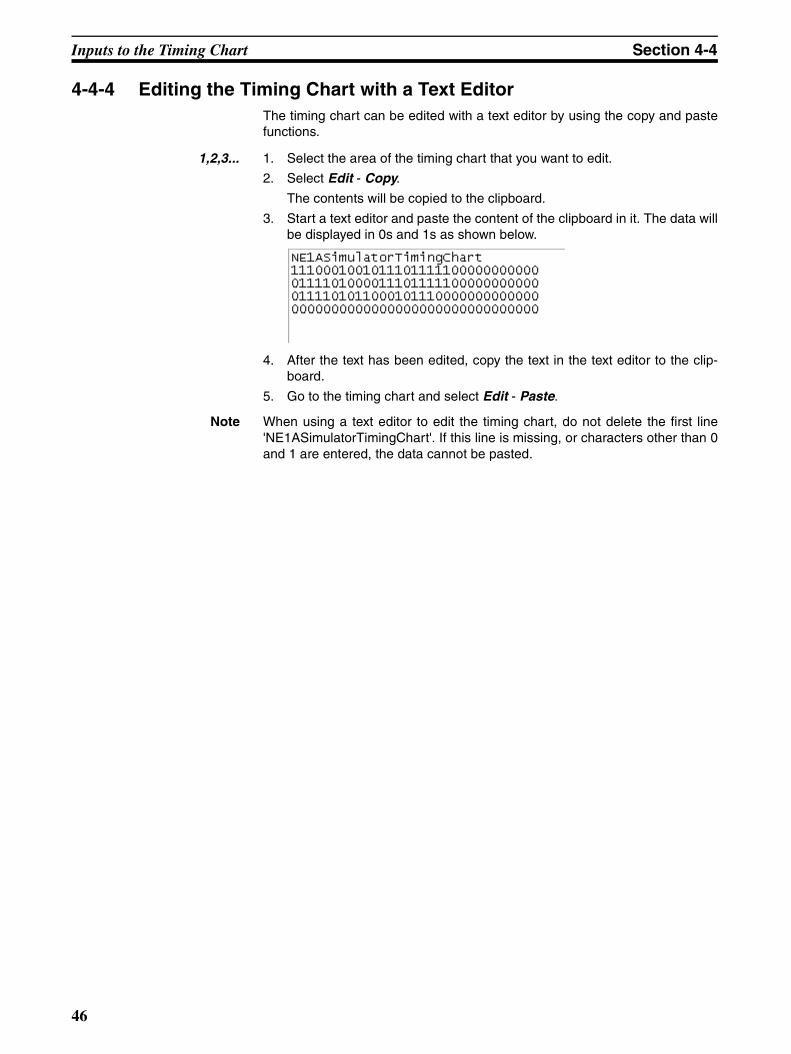
3. Start a text editor and paste the content of the clipboard in it. The data willbe displayed in 0s and 1s as shown below.
4. After the text has been edited, copy the text in the text editor to the clip-board.
5. Go to the timing chart and select Edit - Paste.
Note When using a text editor to edit the timing chart, do not delete the first line'NE1ASimulatorTimingChart'. If this line is missing, or characters other than 0and 1 are entered, the data cannot be pasted.
46

Starting and Stopping the Timing Chart Section 4-5
4-5 Starting and Stopping the Timing ChartThis section describes how to start and stop timing chart simulations.
To start timing chart simulations, the logic program must be stopped.
When the timing chart simulation is being executed, the input tags and outputtags that are displayed in the logic window will not be updated. The display willbe updated when the simulation is paused.
The display in the Watch Window will be updated regardless of whether thetiming chart simulation is executing or has stopped.
Starting the Timing Chart
1,2,3... 1. Select Timing Chart - Execute 1 Pulse, or click the Icon on the TimingChart Tool Bar.
The timing chart simulation will be started.
Pulse Execute on the Timing Chart
1,2,3... 1. Select Timing Chart - Execute 1 Pulse, or click the Icon on the TimingChart Tool Bar.
The timing chart simulation will be executed for one pulse.
When it has finished, simulation will be paused.
Stopping the Timing Chart
1,2,3... 1. Select Timing Chart - Stop, or click the Icon on the Timing Chart ToolBar.
The timing chart simulation will be stopped.
When the timing chart simulation is stopped, the input tags displayed in theLogic Window and Watch Window will be set to their initial values.
Pausing the Timing Chart
1,2,3... 1. Select Timing Chart - Pause, or click the Icon on the Timing ChartTool Bar.
The timing chart simulation will be paused.
Note Breakpoints and an I/O breakpoint can be set in the timing chart. Refer to 4-9Breakpoints and 4-10 I/O Breakpoint on for details on setting breakpoints.
47
Importing/Exporting Timing Chart Data Section 4-6
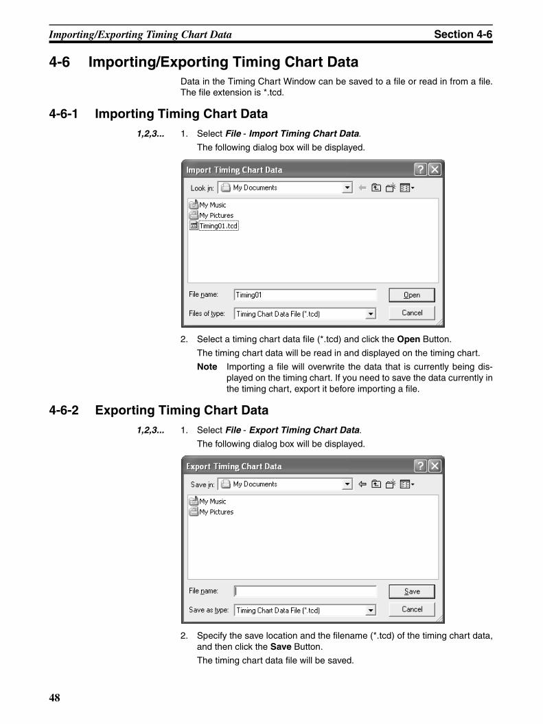
4-6 Importing/Exporting Timing Chart DataData in the Timing Chart Window can be saved to a file or read in from a file.The file extension is *.tcd.
4-6-1 Importing Timing Chart Data1,2,3... 1. Select File - Import Timing Chart Data.
The following dialog box will be displayed.
2. Select a timing chart data file (*.tcd) and click the Open Button.
The timing chart data will be read in and displayed on the timing chart.
Note Importing a file will overwrite the data that is currently being dis-played on the timing chart. If you need to save the data currently inthe timing chart, export it before importing a file.
4-6-2 Exporting Timing Chart Data1,2,3... 1. Select File - Export Timing Chart Data.
The following dialog box will be displayed.
2. Specify the save location and the filename (*.tcd) of the timing chart data,and then click the Save Button.
The timing chart data file will be saved.
48

Importing/Exporting Timing Chart Data Section 4-6
Note The breakpoint information described in 4-9 Breakpoints and 4-10 I/O Break-point will not be included in the timing chart data export file.
49
Printing the Timing Chart Section 4-7
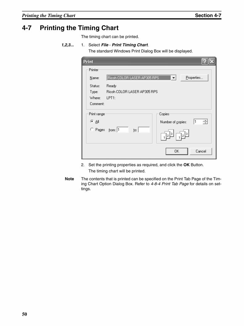
4-7 Printing the Timing ChartThe timing chart can be printed.
1,2,3... 1. Select File - Print Timing Chart.
The standard Windows Print Dialog Box will be displayed.
2. Set the printing properties as required, and click the OK Button.
The timing chart will be printed.
Note The contents that is printed can be specified on the Print Tab Page of the Tim-ing Chart Option Dialog Box. Refer to 4-8-4 Print Tab Page for details on set-tings.
50
Timing Chart Options Section 4-8
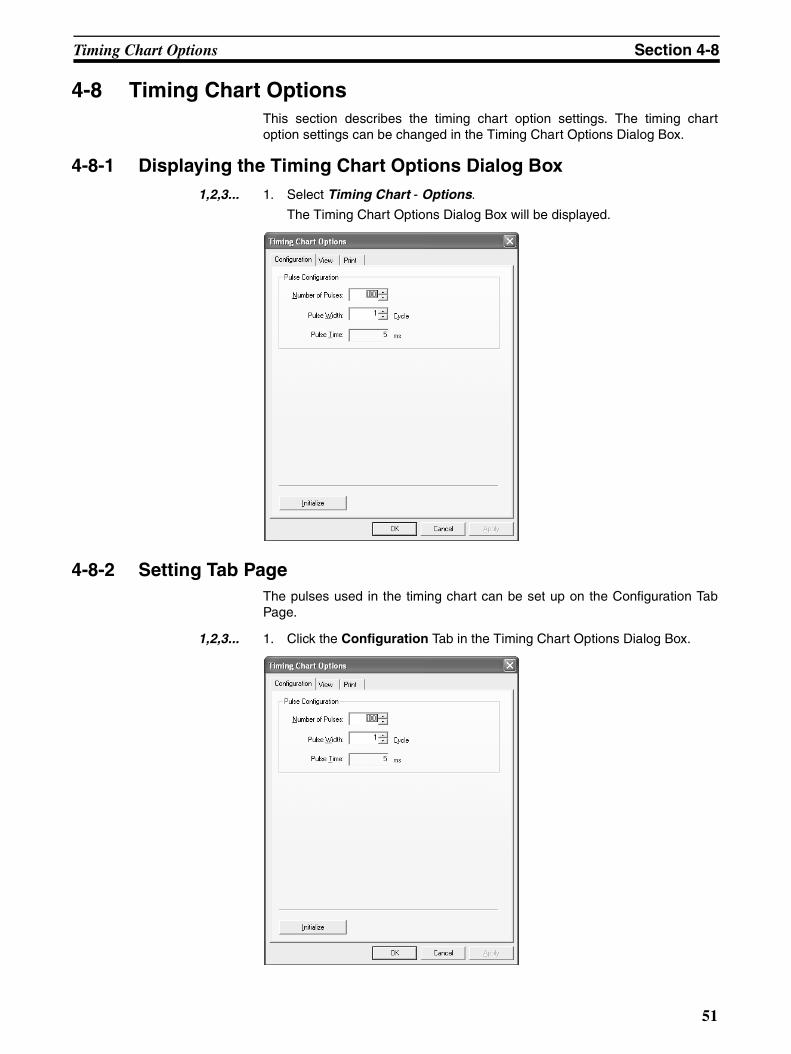
4-8 Timing Chart OptionsThis section describes the timing chart option settings. The timing chartoption settings can be changed in the Timing Chart Options Dialog Box.
4-8-1 Displaying the Timing Chart Options Dialog Box1,2,3... 1. Select Timing Chart - Options.
The Timing Chart Options Dialog Box will be displayed.
4-8-2 Setting Tab PageThe pulses used in the timing chart can be set up on the Configuration TabPage.
1,2,3... 1. Click the Configuration Tab in the Timing Chart Options Dialog Box.
51

Timing Chart Options Section 4-8
The pulse configuration consists of the following items.
2. Modify the pulse settings and click the OK Button.
Note If a value smaller than the current number of pulse is entered, the followingdialog box will be displayed.
Clicking the OK Button will delete the pulses that exceed the set value.
4-8-3 View Tab PageThe display options can be set on the View Tab Page.
1,2,3... 1. Click the Display Tab in the Timing Chart Options Dialog Box.
The display options consist of the following items.
Parameter/button Description
Number of Pulses Specifies the number of pulses that are used in the timing chart. The number of pulses can be set to between 10 and 1,000. (The initial value is 100.)
Pulse Width Specifies the width of one pulse as a multiple of the device cycle time. The pulse width can set to between 1 and 100 cycles. (The initial value is 1 cycle.)
Pulse Time Displays the time of one pulse. (Cycle time (ms) × Pulse width (cycles).)
Initialize Button Returns the number of pulses and pulse width to their initial values.
Parameter/button Description
Pulse Style Used to select block or line.
Color Changes the chart color
52
Timing Chart Options Section 4-8
2. Modify the timing chart view settings and click the OK Button.
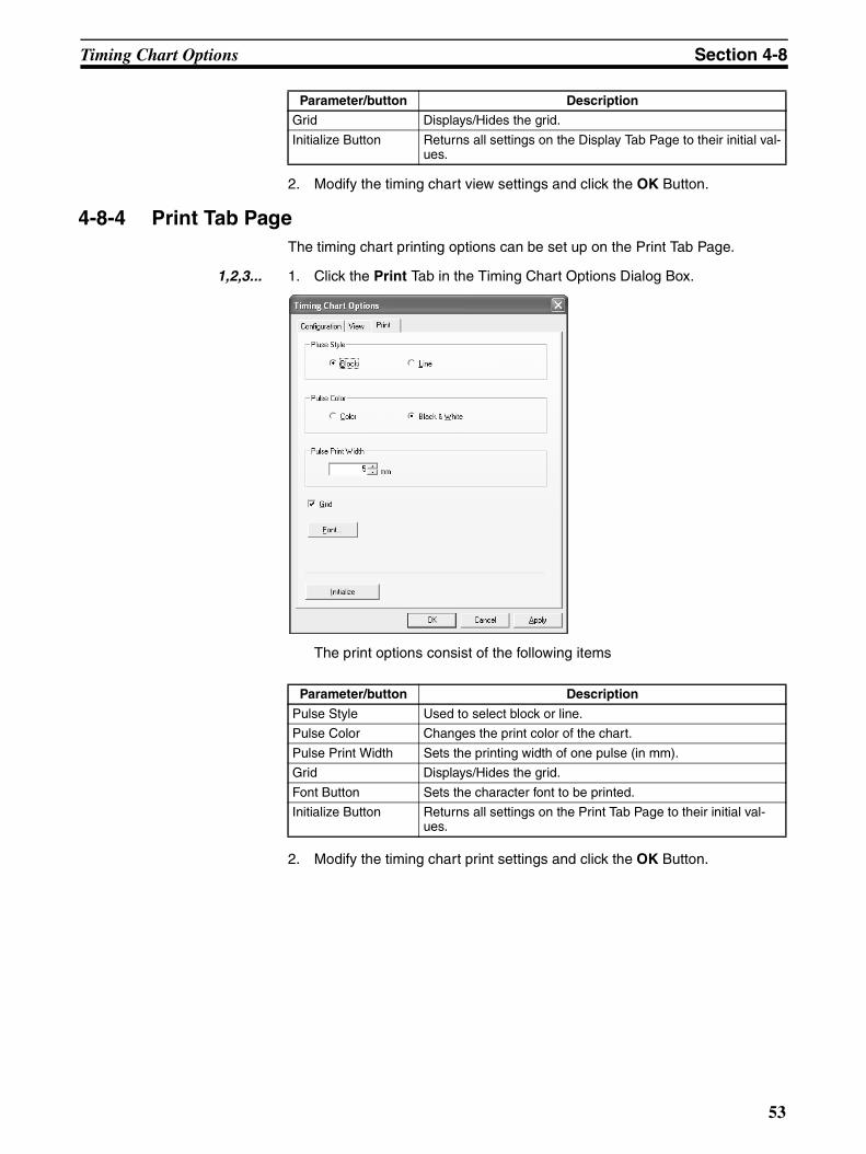
4-8-4 Print Tab PageThe timing chart printing options can be set up on the Print Tab Page.
1,2,3... 1. Click the Print Tab in the Timing Chart Options Dialog Box.
The print options consist of the following items
2. Modify the timing chart print settings and click the OK Button.
Grid Displays/Hides the grid.
Initialize Button Returns all settings on the Display Tab Page to their initial val-ues.
Parameter/button Description
Parameter/button Description
Pulse Style Used to select block or line.
Pulse Color Changes the print color of the chart.
Pulse Print Width Sets the printing width of one pulse (in mm).
Grid Displays/Hides the grid.
Font Button Sets the character font to be printed.
Initialize Button Returns all settings on the Print Tab Page to their initial val-ues.
53
Breakpoints Section 4-9
4-9 BreakpointsWhen a timing chart with breakpoints is executed, it will pause after evaluatingthe row with the breakpoint, allowing you to check the status.
Breakpoints can be temporarily disabled.
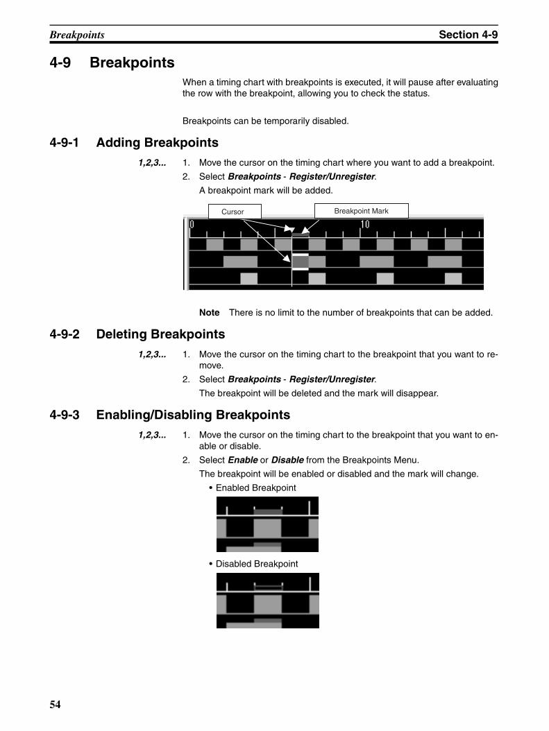
4-9-1 Adding Breakpoints1,2,3... 1. Move the cursor on the timing chart where you want to add a breakpoint.
2. Select Breakpoints - Register/Unregister.
A breakpoint mark will be added.
Note There is no limit to the number of breakpoints that can be added.
4-9-2 Deleting Breakpoints1,2,3... 1. Move the cursor on the timing chart to the breakpoint that you want to re-
move.
2. Select Breakpoints - Register/Unregister.
The breakpoint will be deleted and the mark will disappear.
4-9-3 Enabling/Disabling Breakpoints1,2,3... 1. Move the cursor on the timing chart to the breakpoint that you want to en-
able or disable.
2. Select Enable or Disable from the Breakpoints Menu.
The breakpoint will be enabled or disabled and the mark will change.
• Enabled Breakpoint
• Disabled Breakpoint
Breakpoint MarkCursor
54

Breakpoints Section 4-9
4-9-4 Breakpoint ListBreakpoints can be displayed in a list and be chosen to be removed, enabled,or disabled.
1,2,3... 1. Select Breakpoints - Display Breakpoint List.
The following dialog box will be displayed.
• Each breakpoint can be enabled or disabled using the check boxes onthe left.
2. When the required settings have been completed, click the OK Button.
Button Function
Delete Deletes the selected breakpoint.
Delete All Deletes all breakpoints.
Enable All Enables all breakpoints.
Disable All Disables all breakpoints.
55

I/O Breakpoint Section 4-10
4-10 I/O BreakpointAn I/O breakpoint can be used to pause the timing chart depending on I/Ostatus (ON or OFF).
4-10-1 I/O Breakpoint Settings1,2,3... 1. Select Breakpoints - I/O Breakpoint - Setting.
The setting screen consists of the following parameters.
2. Make the settings as required and click the OK Button.
Parameter Description
Register Break Con-ditions
Select the tags that are used as conditions for the I/O break-point. Set the Condition Option to ON or OFF, and then click the Add Button.The tag will be added to the Applied Condi-tions List. Up to ten tags can be assigned to one I/O break-point as conditions.
Applied Conditions List
Displays a list of conditions for the I/O breakpoint.Select a condition from the list and click the Delete Button to delete the selected condition.
Logic between Con-ditions
If AND is selected, the timing chart will stop when all the applied conditions are met. If OR is selected, the timing chart will stop when at least one of the applied conditions is met.
56
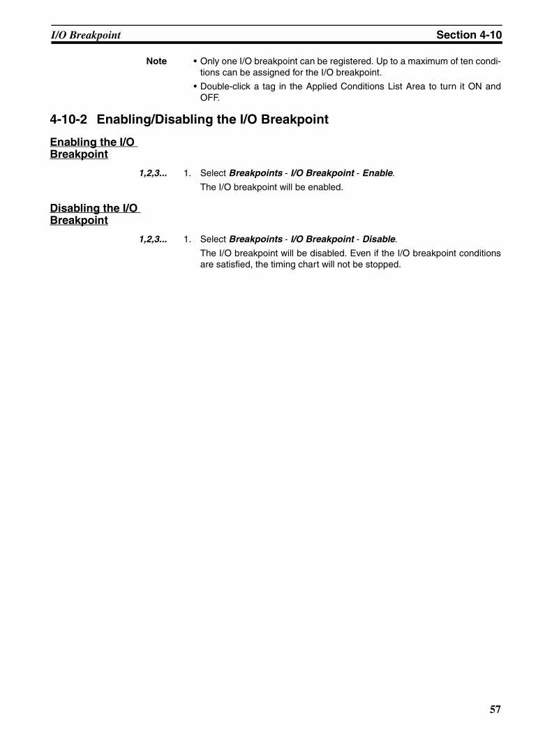
I/O Breakpoint Section 4-10
Note • Only one I/O breakpoint can be registered. Up to a maximum of ten condi-tions can be assigned for the I/O breakpoint.
• Double-click a tag in the Applied Conditions List Area to turn it ON andOFF.
4-10-2 Enabling/Disabling the I/O Breakpoint
Enabling the I/O Breakpoint
1,2,3... 1. Select Breakpoints - I/O Breakpoint - Enable.
The I/O breakpoint will be enabled.
Disabling the I/O Breakpoint
1,2,3... 1. Select Breakpoints - I/O Breakpoint - Disable.
The I/O breakpoint will be disabled. Even if the I/O breakpoint conditionsare satisfied, the timing chart will not be stopped.
57
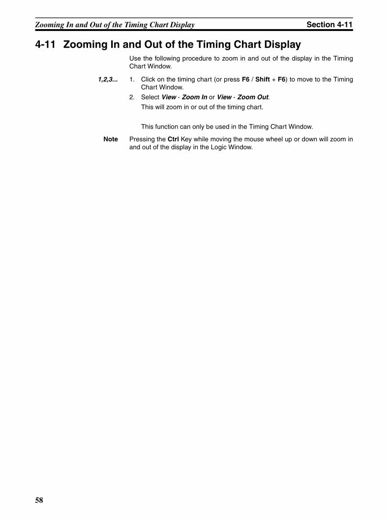
Zooming In and Out of the Timing Chart Display Section 4-11
4-11 Zooming In and Out of the Timing Chart DisplayUse the following procedure to zoom in and out of the display in the TimingChart Window.
1,2,3... 1. Click on the timing chart (or press F6 / Shift + F6) to move to the TimingChart Window.
2. Select View - Zoom In or View - Zoom Out.
This will zoom in or out of the timing chart.
This function can only be used in the Timing Chart Window.
Note Pressing the Ctrl Key while moving the mouse wheel up or down will zoom inand out of the display in the Logic Window.
58

SECTION 5Troubleshooting
This section describes troubleshooting problems that can occur based on error messages displayed by the NE1A LogicSimulator.
5-1 Operating Errors and Countermeasures . . . . . . . . . . . . . . . . . . . . . . . . . . . . . 60
5-1-1 Overview. . . . . . . . . . . . . . . . . . . . . . . . . . . . . . . . . . . . . . . . . . . . . . 60
5-1-2 File Errors . . . . . . . . . . . . . . . . . . . . . . . . . . . . . . . . . . . . . . . . . . . . . 60
5-1-3 Watch Window Errors. . . . . . . . . . . . . . . . . . . . . . . . . . . . . . . . . . . . 61
5-1-4 Debug Errors. . . . . . . . . . . . . . . . . . . . . . . . . . . . . . . . . . . . . . . . . . . 61
5-1-5 Timing Chart Errors . . . . . . . . . . . . . . . . . . . . . . . . . . . . . . . . . . . . . 61
59
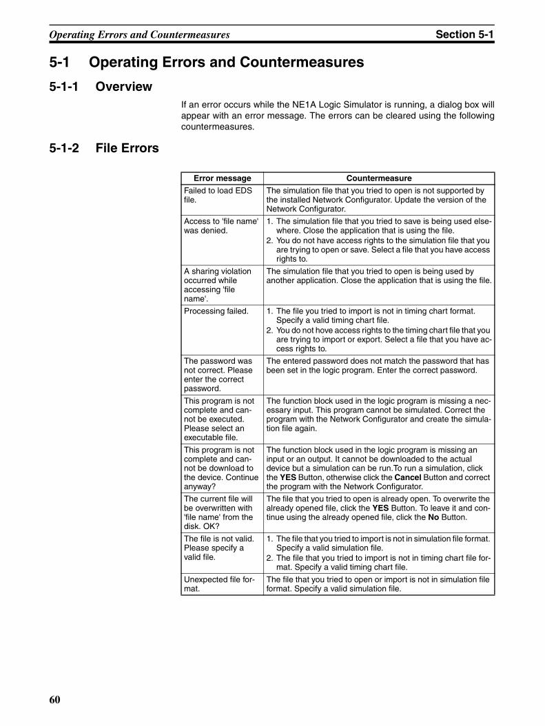
Operating Errors and Countermeasures Section 5-1
5-1 Operating Errors and Countermeasures
5-1-1 OverviewIf an error occurs while the NE1A Logic Simulator is running, a dialog box willappear with an error message. The errors can be cleared using the followingcountermeasures.
5-1-2 File Errors
Error message Countermeasure
Failed to load EDS file.
The simulation file that you tried to open is not supported by the installed Network Configurator. Update the version of the Network Configurator.
Access to 'file name' was denied.
1. The simulation file that you tried to save is being used else-where. Close the application that is using the file.
2. You do not have access rights to the simulation file that you are trying to open or save. Select a file that you have access rights to.
A sharing violation occurred while accessing 'file name'.
The simulation file that you tried to open is being used by another application. Close the application that is using the file.
Processing failed. 1. The file you tried to import is not in timing chart format. Specify a valid timing chart file.
2. You do not hove access rights to the timing chart file that you are trying to import or export. Select a file that you have ac-cess rights to.
The password was not correct. Please enter the correct password.
The entered password does not match the password that has been set in the logic program. Enter the correct password.
This program is not complete and can-not be executed. Please select an executable file.
The function block used in the logic program is missing a nec-essary input. This program cannot be simulated. Correct the program with the Network Configurator and create the simula-tion file again.
This program is not complete and can-not be download to the device. Continue anyway?
The function block used in the logic program is missing an input or an output. It cannot be downloaded to the actual device but a simulation can be run.To run a simulation, click the YES Button, otherwise click the Cancel Button and correct the program with the Network Configurator.
The current file will be overwritten with 'file name' from the disk. OK?
The file that you tried to open is already open. To overwrite the already opened file, click the YES Button. To leave it and con-tinue using the already opened file, click the No Button.
The file is not valid. Please specify a valid file.
1. The file that you tried to import is not in simulation file format. Specify a valid simulation file.
2. The file that you tried to import is not in timing chart file for-mat. Specify a valid timing chart file.
Unexpected file for-mat.
The file that you tried to open or import is not in simulation file format. Specify a valid simulation file.
60
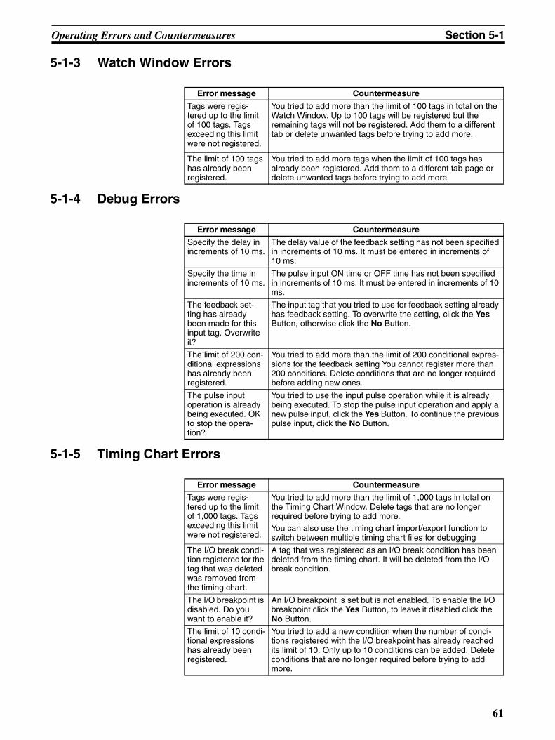
Operating Errors and Countermeasures Section 5-1
5-1-3 Watch Window Errors
5-1-4 Debug Errors
5-1-5 Timing Chart Errors
Error message Countermeasure
Tags were regis-tered up to the limit of 100 tags. Tags exceeding this limit were not registered.
You tried to add more than the limit of 100 tags in total on the Watch Window. Up to 100 tags will be registered but the remaining tags will not be registered. Add them to a different tab or delete unwanted tags before trying to add more.
The limit of 100 tags has already been registered.
You tried to add more tags when the limit of 100 tags has already been registered. Add them to a different tab page or delete unwanted tags before trying to add more.
Error message Countermeasure
Specify the delay in increments of 10 ms.
The delay value of the feedback setting has not been specified in increments of 10 ms. It must be entered in increments of 10 ms.
Specify the time in increments of 10 ms.
The pulse input ON time or OFF time has not been specified in increments of 10 ms. It must be entered in increments of 10 ms.
The feedback set-ting has already been made for this input tag. Overwrite it?
The input tag that you tried to use for feedback setting already has feedback setting. To overwrite the setting, click the Yes Button, otherwise click the No Button.
The limit of 200 con-ditional expressions has already been registered.
You tried to add more than the limit of 200 conditional expres-sions for the feedback setting You cannot register more than 200 conditions. Delete conditions that are no longer required before adding new ones.
The pulse input operation is already being executed. OK to stop the opera-tion?
You tried to use the input pulse operation while it is already being executed. To stop the pulse input operation and apply a new pulse input, click the Yes Button. To continue the previous pulse input, click the No Button.
Error message Countermeasure
Tags were regis-tered up to the limit of 1,000 tags. Tags exceeding this limit were not registered.
You tried to add more than the limit of 1,000 tags in total on the Timing Chart Window. Delete tags that are no longer required before trying to add more.You can also use the timing chart import/export function to switch between multiple timing chart files for debugging
The I/O break condi-tion registered for the tag that was deleted was removed from the timing chart.
A tag that was registered as an I/O break condition has been deleted from the timing chart. It will be deleted from the I/O break condition.
The I/O breakpoint is disabled. Do you want to enable it?
An I/O breakpoint is set but is not enabled. To enable the I/O breakpoint click the Yes Button, to leave it disabled click the No Button.
The limit of 10 condi-tional expressions has already been registered.
You tried to add a new condition when the number of condi-tions registered with the I/O breakpoint has already reached its limit of 10. Only up to 10 conditions can be added. Delete conditions that are no longer required before trying to add more.
61
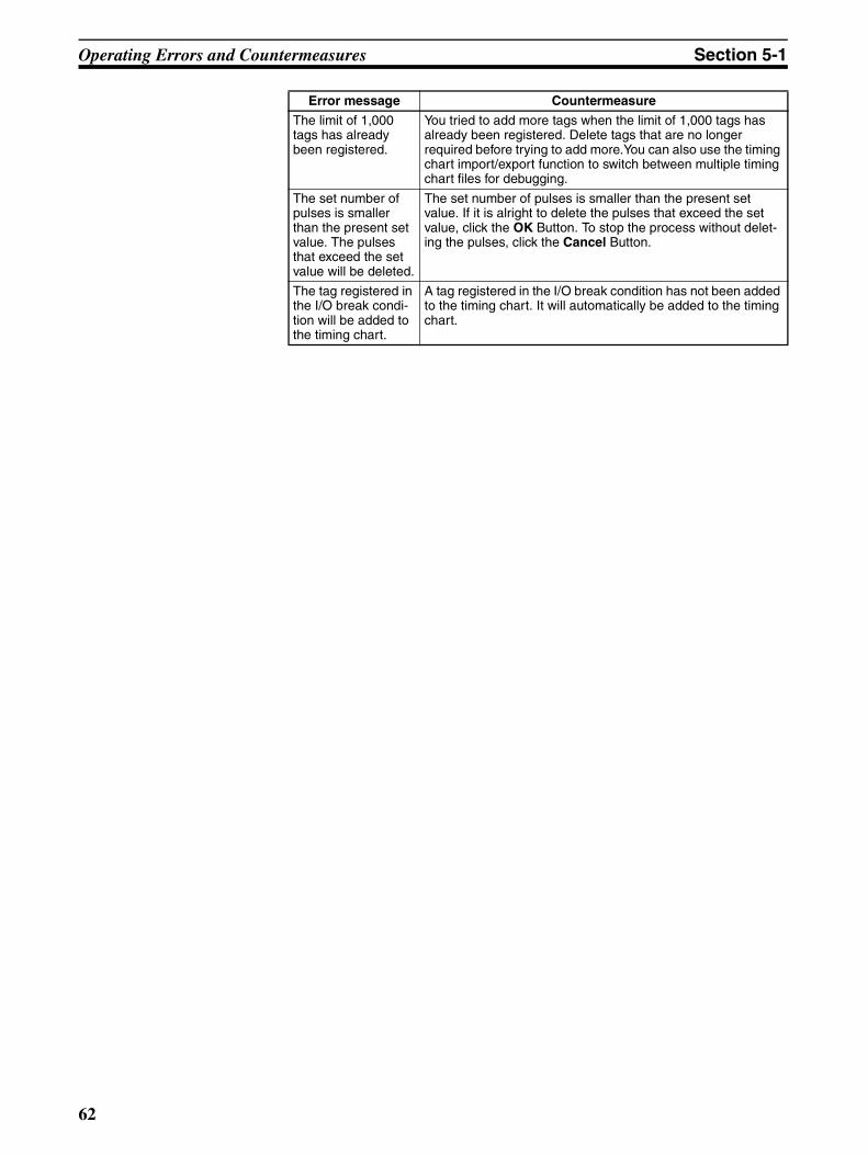
Operating Errors and Countermeasures Section 5-1
The limit of 1,000 tags has already been registered.
You tried to add more tags when the limit of 1,000 tags has already been registered. Delete tags that are no longer required before trying to add more.You can also use the timing chart import/export function to switch between multiple timing chart files for debugging.
The set number of pulses is smaller than the present set value. The pulses that exceed the set value will be deleted.
The set number of pulses is smaller than the present set value. If it is alright to delete the pulses that exceed the set value, click the OK Button. To stop the process without delet-ing the pulses, click the Cancel Button.
The tag registered in the I/O break condi-tion will be added to the timing chart.
A tag registered in the I/O break condition has not been added to the timing chart. It will automatically be added to the timing chart.
Error message Countermeasure
62

Appendix AShortcut Key List
The shortcut keys for the NE1A Logic Simulator are listed in the following tables.
Common to All Windows
Logic Window
Function Menu Shortcut key
Starting debugging Debug - Start F5
Executing one cycle Debug - Execute 1 Cycle F10
Pausing debugging Debug - Pause Ctrl + F5
Stopping debugging Debug - Stop Shift + F5
Executing a timing chart Timing Chart - Execute F7
Pulsing execution of a timing chart Timing Chart - Execute 1 Pulse F8
Pausing a timing chart Timing Chart - Pause Ctrl + F7
Stopping a timing chart Timing Chart - Stop Shift + F7
Adding a tag to a timing chart Timing Chart - Add Tag Insert
Adding a tag to the Watch Window Watch - Add Tag Ctrl + Insert
Opening a file File - Open Ctrl + O
Saving a file File - Save Ctrl + S
Moving to the next pane View - Next Pane F6
Moving to the previous pane View - Previous Pane Shift + F6
Canceling a selected function or close --- Esc
Selecting a menu item --- Alt + Letter next to the menu item
Displaying help Help - Topics F1
Function Menu Shortcut key
Moving up a page ↑Moving down a page ↓Moving right in a page →Moving Left in a page ←Moving to the next page Page Up
Moving to the previous page Page Down
Setting Debug - Set Ctrl + J(Only works when one or more tags are selected)
Resetting Debug - Reset Ctrl + K(Only works when one or more tags are selected)
Reversing Debug - Reverse Ctrl + R
(Only works when one or more tags are selected)
63

Shortcut Key List Appendix A
Tag List Window
Timing Chart Window (Tag)
Timing Chart Window (Chart)
Function Menu Shortcut key
Setting Debug - Set Ctrl + J
Resetting Debug - Reset Ctrl + K
Reversing Debug - Reverse Ctrl + R
Function Menu Shortcut key
Moving up one line ↑Moving down one line ↓Moving right within a window →Moving left within a window ←Selecting the tags on the previous page
Page Up
Selecting the tags on the next page Page Down
Deleting tags Edit - Delete Del
Function Menu Shortcut key
Moving the cursor up ↑Moving the cursor down ↓Moving the cursor to the right →Moving the cursor to the left ←Moving the cursor up one page Page Up
Moving the cursor down one page Page Down
Moving to home Home
Moving to end End
Copying Edit - Copy Ctrl + C
Pasting Edit - Paste Ctrl + V
Turning ON the chart display Timing Chart - ON S
Turning OFF the chart display Timing Chart - OFF R
Reversing the chart display Timing Chart - Reverse Space
Registering/Unregistering breakpoints Breakpoints - Register/Unregister F9
Deleting all breakpoints Breakpoints- Delete All Shift + F9
64

Shortcut Key List Appendix A
Watch WindowFunction Menu Shortcut key
Deleting Edit - Delete Del
Moving up one line ↑Moving down one line ↓Moving right within page →Moving left within page ←Moving one page up Page Up
Moving one page down Page Down
Setting Debug - Set Ctrl + J
Resetting Debug - Reset Ctrl + K
Reversing Debug - Reserve Ctrl + R
65

Shortcut Key List Appendix A
66
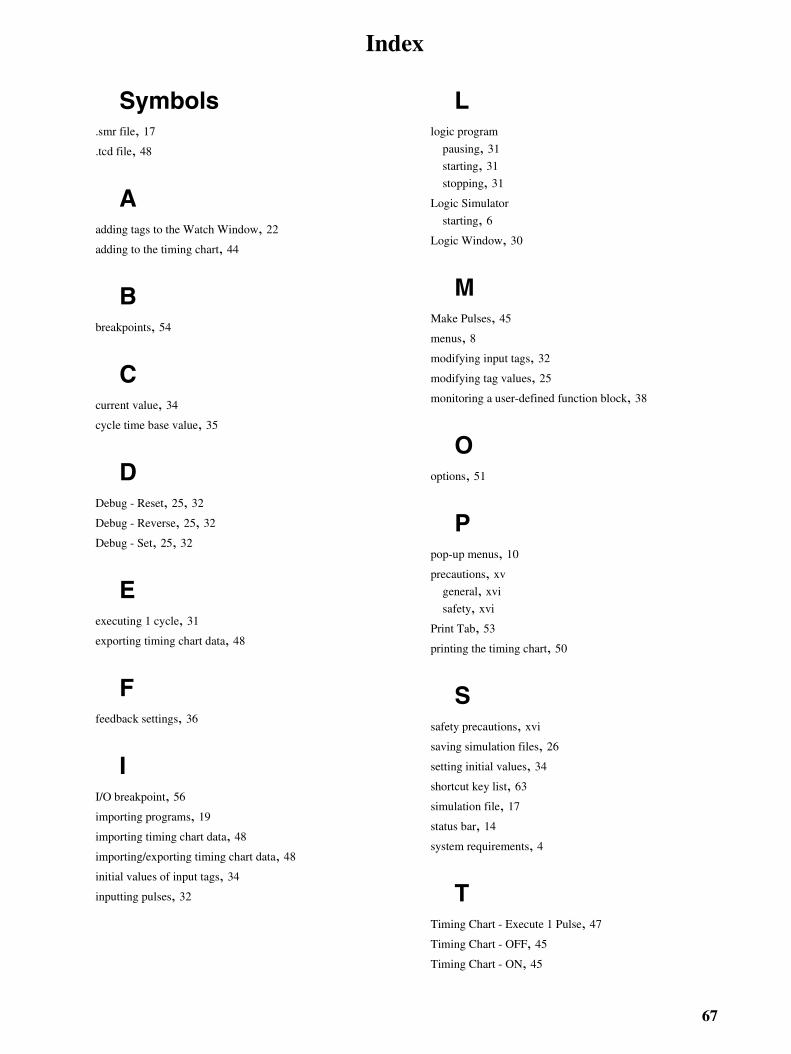
Index
Symbols.smr file, 17
.tcd file, 48
Aadding tags to the Watch Window, 22
adding to the timing chart, 44
Bbreakpoints, 54
Ccurrent value, 34
cycle time base value, 35
DDebug - Reset, 25, 32
Debug - Reverse, 25, 32
Debug - Set, 25, 32
Eexecuting 1 cycle, 31
exporting timing chart data, 48
Ffeedback settings, 36
II/O breakpoint, 56
importing programs, 19
importing timing chart data, 48
importing/exporting timing chart data, 48
initial values of input tags, 34
inputting pulses, 32
Llogic program
pausing, 31
starting, 31
stopping, 31
Logic Simulator
starting, 6Logic Window, 30
MMake Pulses, 45
menus, 8modifying input tags, 32
modifying tag values, 25
monitoring a user-defined function block, 38
Ooptions, 51
Ppop-up menus, 10
precautions, xv
general, xvi
safety, xvi
Print Tab, 53
printing the timing chart, 50
Ssafety precautions, xvi
saving simulation files, 26
setting initial values, 34
shortcut key list, 63
simulation file, 17
status bar, 14
system requirements, 4
TTiming Chart - Execute 1 Pulse, 47
Timing Chart - OFF, 45
Timing Chart - ON, 45
67

Index
Timing Chart - Reverse, 45
timing chart options, 51
Timing Chart Window, 43
tool bars, 11
Vversions, 27
WWatch Window, 22
Zzooming in, 58
zooming out, 58
68
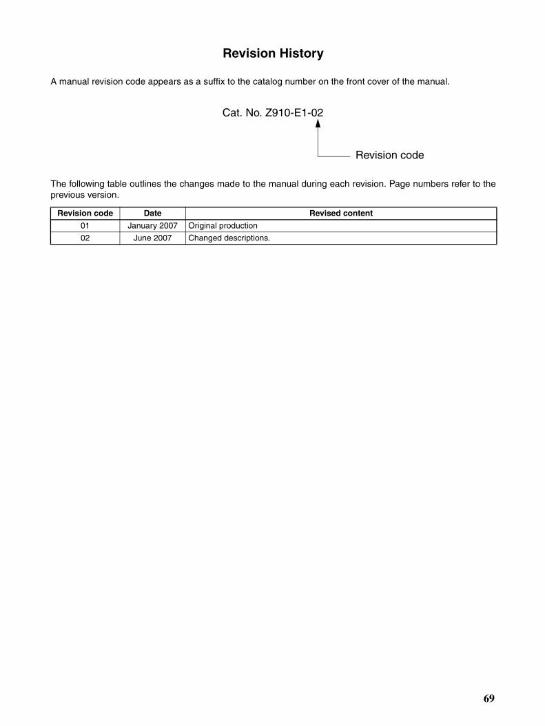
Revision History
A manual revision code appears as a suffix to the catalog number on the front cover of the manual.
The following table outlines the changes made to the manual during each revision. Page numbers refer to theprevious version.
Revision code Date Revised content
01 January 2007 Original production
02 June 2007 Changed descriptions.
Cat. No. Z910-E1-02
Revision code
69

Revision History
70