NE-EO-CALC-2013-005 slow tuner analysis 20131002
24
Page 1 of 25 Title: Structural Analysis of PXIE HWR162 Cavity with Slow Tuner Loading Calculation No.: NE-EO-2013-005 Revision Number: 0 CALCULATION COVER SHEET Supersedes Calculation No.: Total Number of Attachments: Analyzed System: PXIE HWR162 Purpose of Revision: Initial Issue PREPARER Richard L. Fischer Print Name Signature Date REVIEWER Print Name Signature Date VENDOR APPROVER (if vendor-supplied calculation) n.a. Print Name Signature Date FINAL APPROVER Print Name Signature Date
Transcript of NE-EO-CALC-2013-005 slow tuner analysis 20131002

Page 1 of 25
Title: Structural Analysis of PXIE HWR162 Cavity with Slow Tuner Loading
Calculation No.: NE-EO-2013-005 Revision Number: 0
CALCULATION COVER SHEET
Supersedes Calculation No.:
Total Number of Attachments:
Analyzed System:
PXIE HWR162
Purpose of Revision: Initial Issue
PREPARER
Richard L. Fischer
Print Name Signature Date
REVIEWER
Print Name Signature Date
VENDOR APPROVER (if vendor-supplied calculation)
n.a.
Print Name Signature Date
FINAL APPROVER
Print Name Signature Date

Page 2 of 25
Title: Structural Analysis of PXIE HWR162 Cavity with Slow Tuner Loading
Calculation No.: NE-EO-2013-005 Revision Number: 0
TABLE OF CONTENTS
COVER SHEET 1
TABLE OF CONTENTS 2
LIST OF EFFECTIVE PAGES 3
1. Objectives ........................................................................................................................... 4
2. Scope ................................................................................................................................... 4
3. Background ......................................................................................................................... 4
4. Methodology ....................................................................................................................... 4
5. Overview of Analysis ......................................................................................................... 4
6. Assumptions ........................................................................................................................ 4
7. Geometry............................................................................................................................. 5
8. Material Properties .............................................................................................................. 6
9. Boundary Conditions .......................................................................................................... 7
10. Solution and Results ......................................................................................................... 11
11. Discussion ......................................................................................................................... 21
12. Conclusions ....................................................................................................................... 21
13. References ......................................................................................................................... 21
14. Software ............................................................................................................................ 22
APPENDICES
Appendix 1 - General Checking Criteria Sheet………………………………………………….33

Page 3 of 25
Title: Structural Analysis of PXIE HWR162 Cavity with Slow Tuner Loading
Calculation No.: NE-EO-2013-005 Revision Number: 0
LIST OF EFFECTIVE PAGES
Pages Revision
1 to 25 0

Page 4 of 25
Title: Structural Analysis of PXIE HWR162 Cavity with Slow Tuner Loading
Calculation No.: NE-EO-2013-005 Revision Number: 0
1. Objectives The objective of this analysis was to determine compliance of the PXIE HWR162 Cavity with the Fermi National Accelerator Laboratory Environmental Safety and Health Manual (FESHM) when subjected to slow tuner loads.
2. Scope The scope of this analysis was limited to the PXIE HWR162 Cavity.
3. Background Project X is a high intensity proton facility intended to support a world-leading physics program at FermiLab, and will provide high intensity beams for various particle and energy experiments. The Project X Injector Experiment (PXIE) will be an integrated systems test for the Project X front end linear accelerator aimed at validating the concept for the Project X front end. A major subsystem of PXIE is a low-beta superconducting cryomodule that contains eight 162 MHz half wave resonators. These resonators are the object of this analysis.
4. Methodology FESHM chapter 5031.6 and Technical Division Technical Note TD-09-005 (Ref.1) cite the ASME Boiler and Pressure Vessel Code (BPVC) and recommend the Design by Analysis method outlined in Section VIII, Division 2, Part 5 (Ref. 2). This method utilizes finite element analysis. A finite element model of the HWR162 was created with the Ansys finite element program and subjected to pressure, gravity, hydrostatic and temperature loading and analyzed to find component stresses. These stresses were then compared to allowables defined per the BPVC.
5. Overview of Analysis A total of five analyses were conducted and are summarized in Table 1.
Analysys
Case
Failure
ModeCriteria
Analysis
ToolMaterial Model
Nonlinear
Geometry
A Plastic Collapse BPVC Sect. VIII, Div. 2, Part 5.2.3 FEA Elastic, Perfectly Plastic No
B Local Failure BPVC Sect. VIII, Div. 2, Part 5.3.3 FEA Elastic, Plastic Yes
C Collapse from Buckling BPVC Sect. VIII, Div. 2, Part 5.4.1.2.a FEA Elastic, Linear Plastic No
D Ratcheting BPVC Sect. VIII, Div. 2, Part 5.5.7 FEA Elastic, Perfectly Plastic Yes
E Fatigue BPVC Sect. VIII, Div. 2, Part 5.5.2.3 Spreadsheet - - Table 1
Analysis Overview
6. Assumptions This analysis is based on the following assumptions:

Page 5 of 25
Title: Structural Analysis of PXIE HWR162 Cavity with Slow Tuner Loading
Calculation No.: NE-EO-2013-005 Revision Number: 0
1. Loads are steady state (no fatigue or inertial effects).
2. Material response is constant with time (no effects of aging, creep, etc).
3. Materials are isotropic and homogeneous.
4. Residual stresses are not included.
5. Effects of flow or sloshing of the helium are negligible.
6. All welds are full penetration welds.
7. Geometry The cavity consists of a niobium vacuum chamber and a surrounding 304 stainless steel helium jacket. They are rigidly connected at the beam ports by brazing, and flexible 316L stainless steel bellows are used as static seals between the stainless steel helium jacket and the cavity at the power coupler and the 4 toroid coupling ports. The finite element model was constructed by opening Autodesk Inventor assembly file FNAL_HWR162_Assembly.iam, as supplied by Zachary Conway, Physics Department, Argonne National Laboratory, and converting it to STEP format. This STEP file was then read into the Ansys Design Modeler geometry module, where a half symmetry solid model was created. This model is shown in Figure 1. The solid model was meshed with 598,655 quadratic elements. Ten-node tetrahedral solid elements were used everywhere except in the bellows where eight node quad shell elements were used. The bellows were connected to the vacuum chamber and helium jacket with line-to-line bonded contact. Bonded contact was also used to connect the doublers to the reentrant noses and at the niobium to stainless interface at the beam ports. This model is shown in Figure 2.
Figure 1

Page 6 of 25
Title: Structural Analysis of PXIE HWR162 Cavity with Slow Tuner Loading
Calculation No.: NE-EO-2013-005 Revision Number: 0
Solid Geometry Model
Figure 2
Finite Element Model
8. Material Properties The vacuum chamber is fabricated from high purity niobium. The helium jacket shell is fabricated from joint certified 304/304L stainless steel sheet that is certified to 304SS mechanical properties, while various flanges and attachments to the helium jacket are made from 304SS. The bellows are fabricated from 316L stainless. Material properties used in this analysis are given in Table 2.
The elastic, perfectly plastic (EPP) material models used for the Plastic Collapse and Ratcheting analysis were bilinear, isotropic (BISO) hardening models with a yield point set to Sy in Table 2 and a tangent modulus of zero. For the Local Failure analysis, an EPP material was used for the niobium as before, but the 304 stainless steel helium jacket used an elastic, linear plastic material (ELP) with a yield point of Sy and a tangent modulus of 788 ksi as calculated using equation 3-D.16 in Annex 3D, Strength Parameters, in Ref. 2.

Page 7 of 25
Title: Structural Analysis of PXIE HWR162 Cavity with Slow Tuner Loading
Calculation No.: NE-EO-2013-005 Revision Number: 0
ρ
E (psi)
ν
Temp.(°K) 2 293 2 293 2 293
Su (psi) 87000 (a) 16600 (a) 168000 (d) 70000 (b) 168000 (d) 70000 (b)
Sy (psi) 46000 (a) 5500 (a) 39000 (e) 30000 (b) 32500 (e) 25000 (b)
S (psi) 24900 (f) 3700 (f) 26000 (e) 20000 (b) 21700 (e) 16700 (b)
Sps (psi)
Secant CTE
(1/°K)0
4.91 x 10⁻⁶
(h)0
10.2 x 10⁻⁶
(h)0
10.2 x 10⁻⁶
(h)
0.286 (c)
g. Ref. 2, 5.5.6.1.d
h. Ref. 6
0.27 (c)
316L SS
51500 (g) 69000 (g) -
Niobium
0.395 (a)
15.2 x 10⁶
(a)
0.396 (a) 0.27 (c)
29.0 x 10⁶
(c)
0.286 (c)
304 SS
29.0 x 10⁶
(c)
Sources
c. Ref. 5
d. Ref. 5, Fig 2.7.1.1.1(b)
e. Ref. 5, Fig 2.7.1.1.1(a)
f. Ref. 8, Table 1-100
a. Ref. 1
b. Ref. 4
Table 2
Material Properties Multiples of these values are used throughout this report and are tabulated below.
Sy (psi) Su (psi) S (psi) 1.5S (psi) 4S (psi) Sy (psi) Su (psi) S (psi) 1.5S (psi) 4S (psi)
Niobium 5500 16600 3,700 5,500 14,800 46,000 87,000 24,900 37,350 99,600
304 SS 30000 70000 20,000 30,000 80,000 39,000 168,000 26,000 39,000 104,000
Material2°KRT
Table 3
Multiples of Material Properties
9. Boundary Conditions The cavity is restrained by applying fixed displacements to the three mounting holes, as shown in Figure 3, so as to provide a kinematic restraint.
Loading comes from multiple sources. Liquid helium fills the space between the helium jacket and the vacuum chamber, and the maximum allowable working pressure (MWAP) is 4 bar at 2 K. When the assembly is cooled to 2 K, differential contraction between the stainless steel and
Page 8 of 25
Title: Structural Analysis of PXIE HWR162 Cavity with Slow Tuner Loading
Calculation No.: NE-EO-2013-005 Revision Number: 0
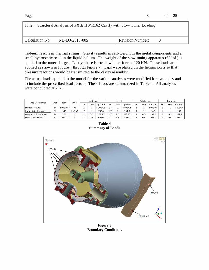
niobium results in thermal strains. Gravity results in self-weight in the metal components and a small hydrostatic head in the liquid helium. The weight of the slow tuning apparatus (62 lbf.) is applied to the tuner flanges. Lastly, there is the slow tuner force of 20 KN. These loads are applied as shown in Figure 4 through Figure 7. Caps were placed on the helium ports so that pressure reactions would be transmitted to the cavity assembly.
The actual loads applied to the model for the various analyses were modified for symmetry and to include the prescribed load factors. These loads are summarized in Table 4. All analyses were conducted at 2 K.
LF SYM Applied LF SYM Applied LF SYM Applied LF SYM Applied
Static Pressure P 4.00E+05 Pa 1.3 1 5.20E+05 1.7 1 6.80E+05 1 1 4.00E+05 1 1 4.00E+05
Hydrostatic Pressure Ph 148 kg/m3 1.3 1 192.4 1.7 1 251.6 1 1 148 1 1 148
Weight of Slow Tuner D 275 N 1.3 0.5 178.75 1.7 0.5 233.75 1 0.5 137.5 1 0.5 137.5
Slow Tuner Force L 20000 N 1.7 0.5 17000 1.7 0.5 17000 1 0.5 10000 1 0.5 10000
Load DescriptionBuckling
Load Base UnitsLimit Load Local Ratcheting
Table 4
Summary of Loads
Figure 3
Boundary Conditions

Page 9 of 25
Title: Structural Analysis of PXIE HWR162 Cavity with Slow Tuner Loading
Calculation No.: NE-EO-2013-005 Revision Number: 0
Figure 4
Pressure Loading
Figure 5
Hydrostatic Pressure of Helium

Page 10 of 25
Title: Structural Analysis of PXIE HWR162 Cavity with Slow Tuner Loading
Calculation No.: NE-EO-2013-005 Revision Number: 0
Figure 6
Gravity Loads
Figure 7
Slow Tuner Loads
Page 11 of 25
Title: Structural Analysis of PXIE HWR162 Cavity with Slow Tuner Loading
Calculation No.: NE-EO-2013-005 Revision Number: 0
10. Solution and Results A. Protection Against Plastic Collapse
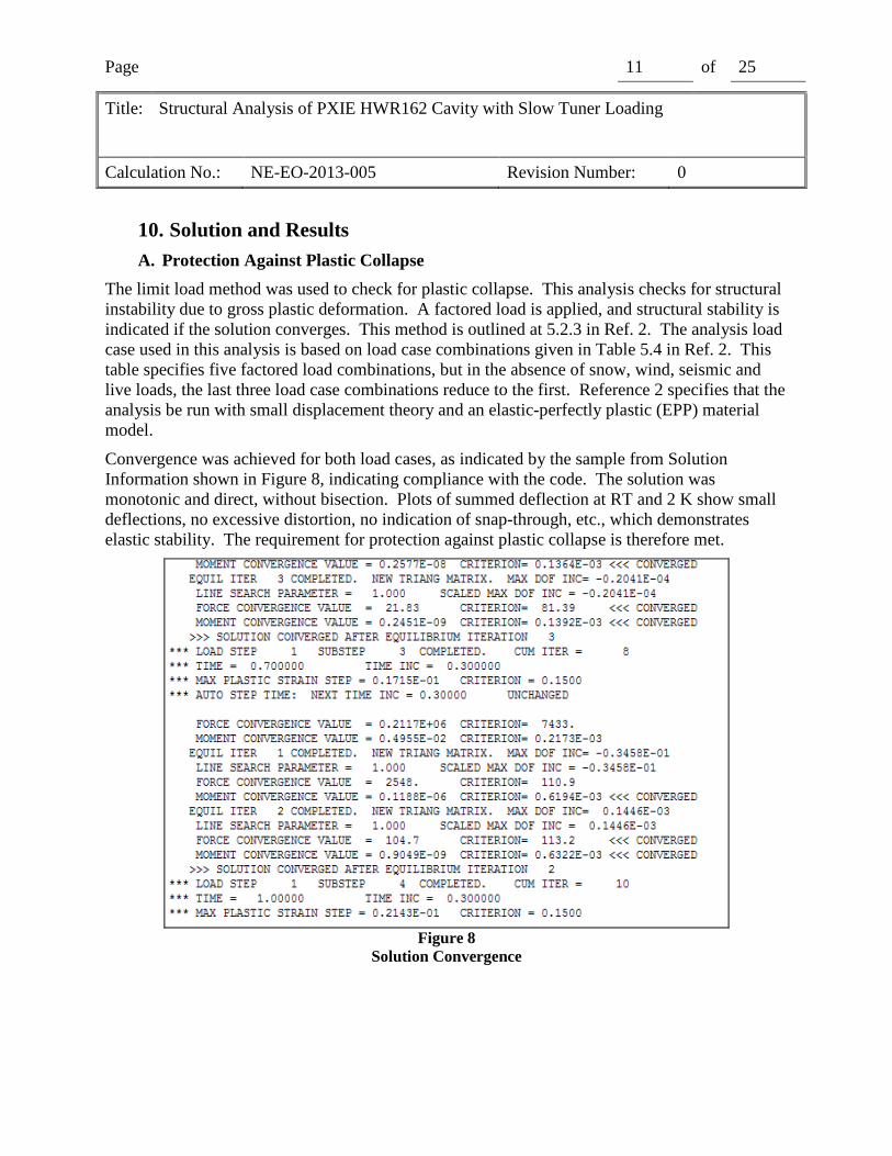
The limit load method was used to check for plastic collapse. This analysis checks for structural instability due to gross plastic deformation. A factored load is applied, and structural stability is indicated if the solution converges. This method is outlined at 5.2.3 in Ref. 2. The analysis load case used in this analysis is based on load case combinations given in Table 5.4 in Ref. 2. This table specifies five factored load combinations, but in the absence of snow, wind, seismic and live loads, the last three load case combinations reduce to the first. Reference 2 specifies that the analysis be run with small displacement theory and an elastic-perfectly plastic (EPP) material model.
Convergence was achieved for both load cases, as indicated by the sample from Solution Information shown in Figure 8, indicating compliance with the code. The solution was monotonic and direct, without bisection. Plots of summed deflection at RT and 2 K show small deflections, no excessive distortion, no indication of snap-through, etc., which demonstrates elastic stability. The requirement for protection against plastic collapse is therefore met.
Figure 8
Solution Convergence

Page 12 of 25
Title: Structural Analysis of PXIE HWR162 Cavity with Slow Tuner Loading
Calculation No.: NE-EO-2013-005 Revision Number: 0
Figure 9
Summed Deflection in mm @ 20 KN Slow Tuner Load
Figure 10
Von Mises Stress in psi @ 20 KN Slow Tuner Load
B. Protection Against Local Failure
Page 13 of 25
Title: Structural Analysis of PXIE HWR162 Cavity with Slow Tuner Loading
Calculation No.: NE-EO-2013-005 Revision Number: 0
Protection from local failure was demonstrated with the Elastic-Plastic analysis method in 5.3.3 for Ref. 2. This method is based on an elastic-plastic material model and specifies the use of non-linear geometry. The acceptance criterion is that the total plastic strain be less than the limiting triaxial strain. The analysis load case used in this analysis is based on Table 5.5, Local Criteria, in Ref. 2.
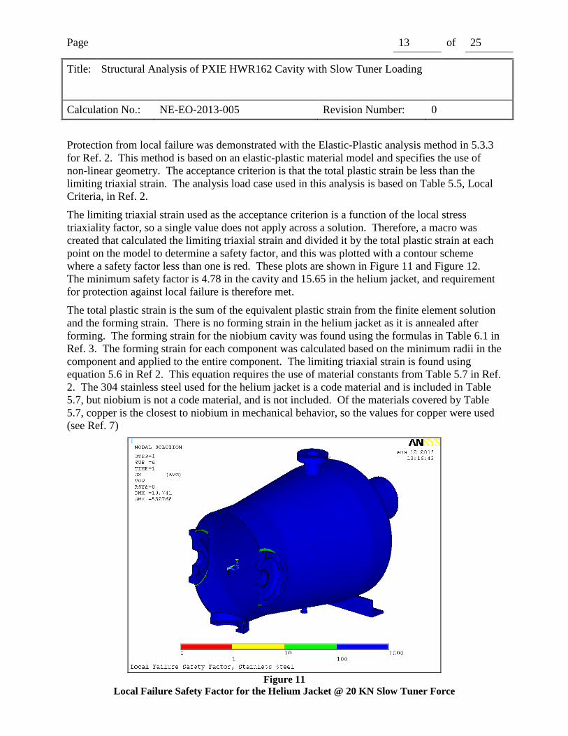
The limiting triaxial strain used as the acceptance criterion is a function of the local stress triaxiality factor, so a single value does not apply across a solution. Therefore, a macro was created that calculated the limiting triaxial strain and divided it by the total plastic strain at each point on the model to determine a safety factor, and this was plotted with a contour scheme where a safety factor less than one is red. These plots are shown in Figure 11 and Figure 12. The minimum safety factor is 4.78 in the cavity and 15.65 in the helium jacket, and requirement for protection against local failure is therefore met.
The total plastic strain is the sum of the equivalent plastic strain from the finite element solution and the forming strain. There is no forming strain in the helium jacket as it is annealed after forming. The forming strain for the niobium cavity was found using the formulas in Table 6.1 in Ref. 3. The forming strain for each component was calculated based on the minimum radii in the component and applied to the entire component. The limiting triaxial strain is found using equation 5.6 in Ref 2. This equation requires the use of material constants from Table 5.7 in Ref. 2. The 304 stainless steel used for the helium jacket is a code material and is included in Table 5.7, but niobium is not a code material, and is not included. Of the materials covered by Table 5.7, copper is the closest to niobium in mechanical behavior, so the values for copper were used (see Ref. 7)
Figure 11
Local Failure Safety Factor for the Helium Jacket @ 20 KN Slow Tuner Force

Page 14 of 25
Title: Structural Analysis of PXIE HWR162 Cavity with Slow Tuner Loading
Calculation No.: NE-EO-2013-005 Revision Number: 0
Figure 12
Local Failure Safety Factor for the Niobium Cavity @ 20 KN Slow Tuner Force.
C. Protection Against Collapse From Buckling
Protection from collapse from buckling was evaluated using the method given at 5.4.1.2.a in Ref. 2, which specifies a linear elastic pre-stressed eigenvalue buckling analysis. The acceptance criterion is that the buckling load factor Φb be greater than 2/βcr, where βcr is the capacity reduction factor. Since the vacuum chamber contains torispherical heads under external pressure, βcr = 0.124 per 5.4.1.3 in Ref. 2, and Φb becomes 16.13.
A preliminary run produced a first buckling mode at 4.06, and a plot of this mode shape (Figure 13 ) indicates that buckling occurs in the inner conductor. This structure is a cylindrical shell, and the appropriate value for βcr would be 0.80, for a Φb of 2.5. The first buckling mode is well above this, but below 16.13. The buckling analysis was rerun so as to extract all modes under a 16.2 load factor. A total of 64 modes were extracted, and all were inspected to determine the location of the buckling. No buckling took place in the toroids in any of the buckling modes. For this reason it is determined that the requirement of protection against collapse from buckling is met.
The 64 buckling modes are shown in Table 5, and selected modes are shown plotted in Figure 13 through Figure 16.

Page 15 of 25
Title: Structural Analysis of PXIE HWR162 Cavity with Slow Tuner Loading
Calculation No.: NE-EO-2013-005 Revision Number: 0
***** EIGENVALUES (LOAD MULTIPLIERS FOR BUCKLING) *****
*** FROM BLOCK LANCZOS ITERATION ***
SHAPE NUMBER LOAD MULTIPLIER SHAPE NUMBER LOAD MULTIPLIER
1 4.0623552 33 13.493413
2 4.9988352 34 13.800653
3 5.3784049 35 13.966953
4 5.4969533 36 13.977046
5 5.5390630 37 14.060888
6 5.9816420 38 14.071456
7 6.1534688 39 14.107939
8 6.3526697 40 14.214443
9 6.3889774 41 14.274367
10 6.8086761 42 14.294792
11 7.7964820 43 14.308438
12 7.7987634 44 14.329919
13 9.5962853 45 14.448812
14 9.5975694 46 14.660406
15 9.8114527 47 14.674884
16 10.049479 48 14.701328
17 10.612978 49 15.040771
18 10.719340 50 15.070154
19 11.473811 51 15.112435
20 11.605205 52 15.119271
21 11.663502 53 15.154830
22 11.718704 54 15.185314
23 12.067553 55 15.274406
24 12.499051 56 15.405317
25 12.592879 57 15.480274
26 12.615076 58 15.526096
27 13.001441 59 15.690515
28 13.087742 60 15.856267
29 13.161422 61 15.986948
30 13.164666 62 16.137088
31 13.173633 63 16.157046
32 13.443974 64 16.193524 Table 5
Buckling Modes

Page 16 of 25
Title: Structural Analysis of PXIE HWR162 Cavity with Slow Tuner Loading
Calculation No.: NE-EO-2013-005 Revision Number: 0
Figure 13
First Mode, ΦΦΦΦb = 4.06
Figure 14
Tenth Mode, ΦΦΦΦb = 6.81

Page 17 of 25
Title: Structural Analysis of PXIE HWR162 Cavity with Slow Tuner Loading
Calculation No.: NE-EO-2013-005 Revision Number: 0
Figure 15
16th Mode, ΦΦΦΦb = 10.05
Figure 16
52nd Mode, ΦΦΦΦb = 15.12

Page 18 of 25
Title: Structural Analysis of PXIE HWR162 Cavity with Slow Tuner Loading
Calculation No.: NE-EO-2013-005 Revision Number: 0
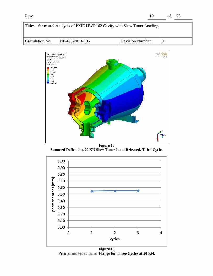
D. Ratcheting Assessment
Protection from Ratcheting was demonstrated with the Elastic Plastic Method described in 5.5.7 in Ref. 2. This method is based on an EPP material model and includes the effects of nonlinear geometry. The acceptance criterion is no change in dimension after a minimum of three loading cycles.
The slow tuner load was applied and released three times, and the deflection of a slow tuner loading flange taken with the load applied and with the load removed was plotted in Figure 19 and Figure 20. As can be seen, both the deflection with load applied and released has stabilized by the end of the third cycle. The requirement for protection from ratcheting is therefore met.
Figure 17
Summed Deflection, 20 KN Slow Tuner Load applied, First Cycle
Page 19 of 25
Title: Structural Analysis of PXIE HWR162 Cavity with Slow Tuner Loading
Calculation No.: NE-EO-2013-005 Revision Number: 0
Figure 18
Summed Deflection, 20 KN Slow Tuner Load Released, Third Cycle.
0.00
0.10
0.20
0.30
0.40
0.50
0.60
0.70
0.80
0.90
1.00
0 1 2 3 4
pe
rma
ne
nt
set
(mm
)
cycles
Figure 19
Permanent Set at Tuner Flange for Three Cycles at 20 KN.

Page 20 of 25
Title: Structural Analysis of PXIE HWR162 Cavity with Slow Tuner Loading
Calculation No.: NE-EO-2013-005 Revision Number: 0
0
0.5
1
1.5
2
2.5
3
3.5
4
4.5
5
0 1 2 3 4
De
fle
ctio
n a
t L
oa
d (
mm
)
cycles
Figure 20 Deflection at Load at Tuner Flange for Three Cycles at 20 KN.
E. Protection Against Failure from Cyclic Loading
Protection against failure from cyclic loading (fatigue) was not evaluated as the screening method presented in 5.5.2.3 of Ref. 2 was used to determine that a fatigue assessment was not required. The steps employed by the screening method are summarized in Table 6. The total number of expected operating cycles is 320, which is less than 1000 cycle value given in Table 5.9 of Ref. 2, for integral construction. Fatigue analysis is therefore not required.
STEP Cycles
Initial Fabrication Testing 20
Initial Cryomodule Cycling 20
30 yrs. @ 4 cycles per year 120
Total 160
2 N∆FP 160
3 N∆PO 0
4 N∆TE 0
5 N∆Tα 160
6 N∆FP + N∆PO + N∆TE + N∆Tα 320
1
Table 6
Summary of Fatigue Screening Results

Page 21 of 25
Title: Structural Analysis of PXIE HWR162 Cavity with Slow Tuner Loading
Calculation No.: NE-EO-2013-005 Revision Number: 0
11. Discussion Use of the BPVC is made difficult because niobium is not a code-recognized material, and Part 3 of the code does not include material data for niobium. Section II, Part D Mandatory Appendix 1 and Mandatory Appendix 5 provide a way around this problem so far as a stress allowable is concerned, but give no help with regards to the determination of the allowable triaxial strain required for the Local Failure analysis. As noted above, material constants for copper were used, based on Ref.7. These specialized material constants are not widely used or available, and mechanical property data for niobium at 2° K is scant, so no conclusion can be drawn about the suitability of this substitution.
Otherwise, this analysis was fairly straight forward. With the exception of the use of more rigorous analysis techniques allowed by the BVPC, the procedures and conventions used here generally follow those in Ref. 9. All evaluations demonstrated that the conditions for protection against failure by plastic collapse, local fracture, buckling, ratcheting and cyclic loading have been met.
12. Conclusions The results of this analysis presented above show that the requirements for Protection Against Plastic Collapse, Protection Against Local Failure, Protection Against Collapse From Buckling, Protection From Ratcheting, Protection Against Failure from Cyclic Loading, per the ASME BPVC, have been met. Based on this, the following conclusion is drawn:
1. The PXIE HWR162 Cavity is in compliance with the Fermi National Accelerator Laboratory Environmental Safety and Health Manual when subjected to the loads described in this analysis.
13. References 1. Technical Division Technical Note TD-09-005, Fermi National Accelerator Laboratory,
Batavia, IL 2010 .
2. ASME Boiler and Pressure Vessel Code, Section VIII, Division 2, Part 5, American Society of Mechanical Engineers, New York, NY 2010.
3. ASME Boiler and Pressure Vessel Code, Section VIII, Division 2, Part 6, American Society of Mechanical Engineers, New York, NY 2010.
4. ASME Electronic Stress Tables, Table 1A, page 18, Line 874, www.est.asme.org/knovel2/asme,
5. Metallic Materials Properties Development and Standardization, DOT/FAA/AR-MMPDS-01, Office of Aviation Research, Washington DC, 2003.
6. Jensen, J.E., et al, Selected Cryogenic Data Handbook, The Bubble Chamber Group, United States Atomic Energy Commission.

Page 22 of 25
Title: Structural Analysis of PXIE HWR162 Cavity with Slow Tuner Loading
Calculation No.: NE-EO-2013-005 Revision Number: 0
7. Schultheiss, T., and Rathke, J., CESR-Type SRG Cavity- Meeting the ASME Pressure Vessel Criteria by Analysis, Proceedings of 2011 Particle Accelerator Conference, New York, NY, March 28, 2011.
8. ASME Boiler and Pressure Vessel Code, Section II, Part D, Mandatory Appendix 1, American Society of Mechanical Engineers, New York, NY 2010.
9. Fischer, R., Calculation Note NE-EO-2012-005, Structural Analysis of PXIE HWR162 Cavity, Argonne National Laboratory, Argonne, IL October 1, 2012.
14. Software
• Ansys Mechanical, Version 13.0, Build date 11/2/2009, Ansys Inc, Pittsburg, PA.
• Microsoft Windows XP Professional x64, Version 2003, Service Pack 2, Microsoft Corporation, Redmond WA.
• Microsoft Office Excel 2007, (12.0.6654,5003) SP3 MSO (12.0.6607.1000), Microsoft Corporation, Redmond WA.

Page 23 of 25
Title: Structural Analysis of PXIE HWR162 Cavity with Slow Tuner Loading
Calculation No.: NE-EO-2013-005 Revision Number: 0
APPENDIX 1 GENERAL CHECKING CRITERIA SHEET
ANALYSIS CHECKLIST Yes No N/A Comments
Are analytical methods appropriate?
Are assumptions appropriate?
Is the analysis complete?
Is the source of the input geometry documented?
Is the source of material properties documented?
Are the boundary conditions clearly explained?
Was an applicable and valid computer program used?
Are the conclusions supported by the results?
Do the results seem reasonable?

Page 24 of 25
Title: Structural Analysis of PXIE HWR162 Cavity with Slow Tuner Loading
Calculation No.: NE-EO-2013-005 Revision Number: 0