NDS NITRO_Programming_Manual_V1_44
388
© 2003-2006 Nintendo NTR-06-0180-001-A9 Released: January 4, 2006 NITRO Programming Manual Version 1.44 CONFIDENTIAL
Transcript of NDS NITRO_Programming_Manual_V1_44

NITRO Programming Manual
Version 1.44
CONFIDENTIAL
© 2003-2006 Nintendo NTR-06-0180-001-A9Released: January 4, 2006

NITRO Programming Manual
Confidential
These coded instructions, statements, and computer programs contain proprietary information of Nintendo of America Inc. and/or Nintendo Company Ltd., and are protected by Federal copyright law. They may not be disclosed to third parties or copied or duplicated in any form, in whole or in part, without the prior written consent of Nintendo.
NTR-06-0180-001-A9 ii © 2003-2006 NintendoReleased: January 4, 2006
Table of Contents1 System.................................................................................................................................................1
1.1 System Outline ..........................................................................................................................11.1.1 NITRO Processor.............................................................................................................21.1.2 Main Memory ...................................................................................................................41.1.3 LCD..................................................................................................................................41.1.4 Digital Keys ......................................................................................................................41.1.5 Touch Screen...................................................................................................................41.1.6 Microphone ......................................................................................................................41.1.7 RTC..................................................................................................................................41.1.8 Wireless Communications................................................................................................51.1.9 Nintendo DS Game Card .................................................................................................51.1.10 DS Accessories................................................................................................................5
1.2 Memory Map..............................................................................................................................61.3 Accessing Devices Connected to the Subprocessor .................................................................81.4 Startup Mode .............................................................................................................................8
1.4.1 NITRO Mode....................................................................................................................81.4.2 AGB Compatibility Mode..................................................................................................8
1.5 Destination.................................................................................................................................82 Memory................................................................................................................................................9
2.1 External Memory......................................................................................................................112.1.1 Main Memory .................................................................................................................13
2.2 The NITRO Processor's Internal Memory................................................................................172.2.1 VRAM.............................................................................................................................172.2.2 Work RAM......................................................................................................................292.2.3 I/O Registers ..................................................................................................................31
2.3 Memory Map for Game Card Boot...........................................................................................323 The Main Processor Core (ARM946E-S) ..........................................................................................35
3.1 The Protection Unit ..................................................................................................................353.2 Tightly Coupled Memory (TCM)...............................................................................................36
3.2.1 Instruction TCM..............................................................................................................363.2.2 Data TCM.......................................................................................................................36
3.3 Cache Memory ........................................................................................................................363.3.1 Instruction Cache ...........................................................................................................373.3.2 The Data Cache.............................................................................................................383.3.3 Cache Operations ..........................................................................................................403.3.4 Optimizing the Cache.....................................................................................................41
3.4 Write Buffer..............................................................................................................................423.4.1 Write Buffer Operations .................................................................................................43
3.5 Ensuring Coherency ................................................................................................................433.5.1 Write-Back Mode ...........................................................................................................433.5.2 Write-Through Mode ......................................................................................................44
4 Display...............................................................................................................................................474.1 Display System ........................................................................................................................474.2 LCD..........................................................................................................................................49
4.2.1 LCD Controller Specifications ........................................................................................494.3 Display Status..........................................................................................................................514.4 Display Control ........................................................................................................................54
4.4.1 Top LCD/Bottom LCD Output Switching........................................................................544.4.2 Display Control of 2D Graphics Engine A ......................................................................554.4.3 2D Graphics Engine B Display Controls ........................................................................574.4.4 Display Modes ...............................................................................................................58
4.5 Display Capture .......................................................................................................................67
© 2003-2006 Nintendo iii NTR-06-0180-001-A9Released: January 4, 2006

NITRO Programming Manual
4.6 Master Brightness....................................................................................................................715 2D Graphics.......................................................................................................................................73
5.1 Controlling the 2D Display .......................................................................................................735.2 BG............................................................................................................................................77
5.2.1 BG Mode........................................................................................................................775.2.2 BG Control .....................................................................................................................815.2.3 Character BG .................................................................................................................885.2.4 Bitmap BG....................................................................................................................1035.2.5 BG Scroll ......................................................................................................................1055.2.6 BG Rotation and Scaling (Affine Transformation) ........................................................106
5.3 OBJ........................................................................................................................................1095.3.1 OBJ Display Control.....................................................................................................1115.3.2 OAM.............................................................................................................................1125.3.3 Character OBJ .............................................................................................................1215.3.4 Bitmap OBJ..................................................................................................................128
5.4 Backdrop................................................................................................................................1355.5 Color Palettes ........................................................................................................................136
5.5.1 Standard Palettes ........................................................................................................1365.5.2 Extended Palettes........................................................................................................137
5.6 Windows ................................................................................................................................1425.6.1 The Precedence of Windows .......................................................................................145
5.7 Color Special Effects .............................................................................................................1465.8 Mosaic ...................................................................................................................................1505.9 Display Priority.......................................................................................................................151
6 3D Graphics.....................................................................................................................................1536.1 3D Display Control.................................................................................................................1556.2 Geometry Engine...................................................................................................................158
6.2.1 Overview ......................................................................................................................1586.2.2 The coordinate system.................................................................................................1586.2.3 Coordinate Transformations.........................................................................................1596.2.4 Projection Transformations ..........................................................................................1616.2.5 Depth Buffering ............................................................................................................1636.2.6 Geometry Commands..................................................................................................1676.2.7 Swapping the Rendering Engine's Reference Data.....................................................1786.2.8 Viewport .......................................................................................................................1806.2.9 Matrices .......................................................................................................................1816.2.10 Light .............................................................................................................................1896.2.11 Material ........................................................................................................................1906.2.12 Polygon Attributes ........................................................................................................1966.2.13 Polygons ......................................................................................................................2006.2.14 Texture Mapping ..........................................................................................................2056.2.15 Tests ............................................................................................................................2156.2.16 Status...........................................................................................................................2186.2.17 Warnings Regarding Calculation Precision..................................................................223
NTR-06-0180-001-A9 iv © 2003-2006 NintendoReleased: January 4, 2006

6.3 Rendering Engine ..................................................................................................................2246.3.1 Overview ......................................................................................................................2246.3.2 Rendering Methods......................................................................................................2266.3.3 Initializing the Rendering Buffers .................................................................................2296.3.4 Rasterizing ...................................................................................................................2336.3.5 Textures .......................................................................................................................2426.3.6 Alpha-Test....................................................................................................................2566.3.7 Alpha-Blending.............................................................................................................2566.3.8 Edge Marking...............................................................................................................2576.3.9 Fog Blending................................................................................................................2586.3.10 Anti-aliasing .................................................................................................................2626.3.11 Status...........................................................................................................................265
6.4 2D Graphics Features You Can Apply to the 3D Screen After Rendering ............................2666.4.1 Raster scroll .................................................................................................................2666.4.2 Order of Display Priority With 2D Screen.....................................................................2666.4.3 Windows ......................................................................................................................2676.4.4 Color Effects ................................................................................................................268
7 DMA.................................................................................................................................................2718 Timer ...............................................................................................................................................2779 Interrupts .........................................................................................................................................279
9.1 The Interrupt Master Enable Register....................................................................................2799.2 The Interrupt Enable Register................................................................................................2809.3 The Interrupt Request Register .............................................................................................2819.4 Interrupt Cautions ..................................................................................................................282
9.4.1 Clearing IME and IE.....................................................................................................2829.4.2 Multiple Interrupts ........................................................................................................2829.4.3 Interrupt Delays During DMA Operation ......................................................................2829.4.4 Interrupts from ARM7...................................................................................................282
10 Power Management ........................................................................................................................28310.1 Sleep Mode............................................................................................................................28310.2 Controlling Various Power Supplies ......................................................................................284
10.2.1 Sound...........................................................................................................................28410.2.2 LCD Backlight ..............................................................................................................28410.2.3 LCD..............................................................................................................................28410.2.4 Microphone ..................................................................................................................28410.2.5 System .........................................................................................................................28410.2.6 Graphics.......................................................................................................................285
10.3 Power Status .........................................................................................................................28810.3.1 Low Battery State.........................................................................................................28810.3.2 DS Open/Closed State.................................................................................................288
11 Accelerators.....................................................................................................................................28911.1 Divider....................................................................................................................................289
11.1.1 Number of Calculation Cycles......................................................................................29111.2 Square-Root Unit ...................................................................................................................292
11.2.1 Number of Calculation Cycles......................................................................................29312 Keys.................................................................................................................................................295
12.1 Input Keys..............................................................................................................................29512.2 Interrupt Handling for Key Input.............................................................................................296
13 Sound ..............................................................................................................................................297
© 2003-2006 Nintendo v NTR-06-0180-001-A9Released: January 4, 2006
NITRO Programming Manual
13.1 Hardware Specifications ........................................................................................................29813.1.1 Data Format .................................................................................................................29813.1.2 Channels......................................................................................................................30013.1.3 Mixer ............................................................................................................................30013.1.4 Master Volume.............................................................................................................30113.1.5 Sound Capture.............................................................................................................30113.1.6 Power Control ..............................................................................................................30113.1.7 Cautions.......................................................................................................................301
13.2 Sound Block Diagrams ..........................................................................................................30213.2.1 Overall Sound ..............................................................................................................30213.2.2 Channels 0 – 3 and Sound Capture 0 - 1 ....................................................................30313.2.3 Channels 4 - 7..............................................................................................................30513.2.4 Channels 8 - 15............................................................................................................30613.2.5 Examples of Using Sound............................................................................................307
13.3 NITRO-Composer..................................................................................................................31013.3.1 The NITRO-Composer Playback Method ....................................................................310
14 Wireless Communications ...............................................................................................................31114.1 Hardware Specifications ........................................................................................................31114.2 Wireless Manager..................................................................................................................311
14.2.1 Internet Play.................................................................................................................31114.2.2 Multi-Card Play ............................................................................................................31214.2.3 Single-Card Play ..........................................................................................................312
15 Touch Panel ....................................................................................................................................31315.1 Touch Panel Structure ...........................................................................................................314
16 Microphone......................................................................................................................................31517 Real-Time Clock (RTC) ...................................................................................................................31718 Internal Flash Memory.....................................................................................................................319
18.1 Touch Panel Calibration Data................................................................................................31918.2 Owner Information Data.........................................................................................................31918.3 NITRO Initial Setting Data .....................................................................................................32018.4 RTC Operation Information Data ...........................................................................................320
Appendix A.Register List........................................................................................................................321A.1 Addresses 0x04000000 and higher .......................................................................................321A.2 Addresses 0x04001000 and higher (2D Graphics Engine B-related)....................................358A.3 Addresses 0x04100000 and higher .......................................................................................361
Appendix B.List of VRAM Data Capacities ............................................................................................365Appendix C.Data Formats......................................................................................................................367
NTR-06-0180-001-A9 vi © 2003-2006 NintendoReleased: January 4, 2006
FiguresFigure 1-1 : The Overall System Block Diagram........................................................................................1Figure 1-2 : ARM9 Overall Memory Map ...................................................................................................7Figure 1-3 : ARM7 Overall Memory Map ...................................................................................................7Figure 2-1 : Transfer Sequence from Main Memory to Work RAM (Basic Cycles).................................14Figure 2-2 : Transfer Sequence from Main Memory to Work RAM (Worst Case) ..................................14Figure 2-3 : Transfer Sequence from Work RAM to Main Memory (Basic Cycles).................................15Figure 2-4 : Transfer Sequence from Main Memory to VRAM (Basic Cycles)........................................15Figure 2-5 : Transfer Sequence from Main Memory to VRAM (Worst Case) .........................................16Figure 2-6 : Transfer Sequence from VRAM to Main Memory (Basic Cycles)........................................16Figure 2-7 : Texture image slot memory map .........................................................................................22Figure 2-8 : Texture Palette Slot Memory Map .......................................................................................25Figure 2-9 : BG Extended Palette Slot Memory Map..............................................................................25Figure 2-10 : OBJ Extended Palette Slot Memory Map ..........................................................................26Figure 2-11 : Memory Maps for Various Settings of ARM9, ARM7 Shared Internal Work RAM ............30Figure 2-12 : Memory Map for Game Card Boot ....................................................................................32Figure 3-1 : Block Diagram of the Main Processor Core ........................................................................35Figure 3-2 : Structure and Actions of the Instruction Cache ...................................................................38Figure 3-3 : Structure and Actions of the Data Cache ............................................................................39Figure 3-4 : Cache line state transitions (write-back mode)....................................................................44Figure 3-5 : Cache line state transitions (write-through mode) ...............................................................45Figure 4-1 : The Display System Block Diagram .....................................................................................48Figure 4-2 : LCD Scan Timing .................................................................................................................49Figure 4-3 : Display Mode Selection (Display Output A Side Only) .........................................................59Figure 4-4 : Display Mode Selection (Display Output A Side Only) .........................................................60Figure 4-5 : An Example of Displaying the Bitmap OBJ Results of 3D Rendering ..................................62Figure 4-6 : The VRAM Address Map of the LCD Pixels .........................................................................63Figure 4-7 : An Example of the Motion Blur Effect that Uses the Display Capture ..................................64Figure 4-8 : The LCD Pixel EVEN/ODD Map of the Main Memory Display FIFO Register .....................66Figure 4-9 : The LCD Pixel Map of the Capture Data (When the Capture Size is 256 x 192 Dots).........69Figure 5-1 : Out-of-Area Processing Method Differences.......................................................................84Figure 5-2 : Text BG Screen Size ...........................................................................................................86Figure 5-3 : Affine BG Screen Size.........................................................................................................87Figure 5-4 : VRAM Offset for BG Character Data...................................................................................89Figure 5-5 : VRAM Offset for BG Screen Data .......................................................................................90Figure 5-6 : 256x256-Dot Address Mapping (Text BG) ..........................................................................92Figure 5-7 : 256x512-Dot Address Mapping (Text BG) ..........................................................................92Figure 5-8 : 512x256-Dot Address Mapping (Text BG) ..........................................................................93Figure 5-9 : 512x512-Dot Address Mapping (Text BG) ..........................................................................93Figure 5-10 : Character Data Address Mapping (Text BG 16-Color Mode)............................................94Figure 5-11 : Character Data Address Mapping (Text BG 256-Color Mode)..........................................95Figure 5-12 : 128X128-Dot Address Mapping (Affine BG)......................................................................97Figure 5-13 : 256x256-Dot Address Mapping (Affine BG) ......................................................................97Figure 5-14 : 512x512-Dot Address Mapping (Affine BG) ......................................................................98Figure 5-15 : 1024x1024-Dot Address Mapping (Affine BG) ..................................................................99Figure 5-16 : Character Data Address Mapping (Affine BG) ................................................................100Figure 5-17 : Character Data Address Mapping (256-Color x 16-Palette Character BG).....................102Figure 5-18 : Offset Schematic .............................................................................................................105Figure 5-19 : BG Rotation and Scaling .................................................................................................106Figure 5-20 : OAM Memory Map (add 0x400h to 2D Graphics Engine B Addresses)..........................112Figure 5-21 : Affine Transformation of Double-Size OBJ Field.............................................................114Figure 5-22 : The Problem of OBJ Wrapping........................................................................................115Figure 5-23 : OBJ Rotation and Scaling ...............................................................................................120
© 2003-2006 Nintendo vii NTR-06-0180-001-A9Released: January 4, 2006

NITRO Programming Manual
Figure 5-24 : Character Data Address Mapping (16-Color Mode Character OBJ) ...............................123Figure 5-25 : Character Data Address Mapping (256-Color Mode Character OBJ) .............................124Figure 5-26 : 2D Mapping .....................................................................................................................125Figure 5-27 : 1D Mapping when Character Name Boundary is 32 Bytes .............................................126Figure 5-28 : 1D Mapping when Character Name Boundary is 128 Bytes ...........................................127Figure 5-29 : 2D Map of Bitmap OBJ Data VRAM (128 Horizontal Dots).............................................131Figure 5-30 : 2D Image Map of Character Name VRAM ......................................................................131Figure 5-31 : 2D Map of Bitmap OBJ Data VRAM (256 Horizontal Dots).............................................132Figure 5-32 : 2D Image Map of Character Name VRAM ......................................................................132Figure 5-33 : 1D Map of VRAM with 8x8-Dot Characters .....................................................................133Figure 5-34 : 1D Map of VRAM with 16x16-Dot Characters .................................................................134Figure 5-35 : Backdrop Schematic........................................................................................................135Figure 5-36 : Standard Palette RAM Addresses (Add 0x400h for 2D Graphics Engine B) ..................136Figure 5-37 : 16 Colors x 16 Palettes ...................................................................................................136Figure 5-38 : 256 Colors x 1 Palette .....................................................................................................136Figure 5-39 : BG Extended Palette Memory Map .................................................................................138Figure 5-40 : OBJ Extended Palette Slot Memory Map ........................................................................141Figure 5-41 : Altering the Window Shape .............................................................................................144Figure 5-42 : The Display Priority of Window 0, Window 1, and the OBJ Window ...............................145Figure 5-43 : Alpha-Blending Display Priority .......................................................................................148Figure 5-44 : Display Changes According to Mosaic Size ....................................................................150Figure 5-45 : Display Priority.................................................................................................................151Figure 6-1 : 3D Graphics Hardware Block Diagram..............................................................................153Figure 6-2 : Right-Handed Coordinate System.....................................................................................158Figure 6-3 : Coordinate Transformation Flow Chart .............................................................................160Figure 6-4 : Perspective Projections .....................................................................................................161Figure 6-5 : Orthogonal Projections ......................................................................................................162Figure 6-6 : Z-Buffering and W-Buffering (Perspective Projection).......................................................164Figure 6-7 : Z-Buffering and W-Buffering (Orthogonal Projection)........................................................166Figure 6-8 : Transferring Packed and Non-Packed Commands ...........................................................168Figure 6-9 : Continuous writing to the Geometry FIFO using STM or STRD Instructions ....................169Figure 6-10 : Case 1: Preventing Commands without Parameters from being the first Valid Command ...170Figure 6-11 : Case 2: Preventing Commands without Parameters from being the first Valid Command ...171Figure 6-12 : When the First Valid Command has no Parameters .......................................................172Figure 6-13 : Schematic of the main Geometry Command processes .................................................177Figure 6-14 : Size and Position of the Viewport....................................................................................180Figure 6-15 : Material Color Schematic ................................................................................................190Figure 6-16 : Directional Vector Relational Diagram (Diffuse Reflection Color) ...................................190Figure 6-17 : Directional Vector Relational Diagram (Specular Reflection Color) ................................191Figure 6-18 : Specular Reflection Shininess.........................................................................................193Figure 6-19 : Order in which the Vertex commands issues vertices.....................................................200Figure 6-20 : Line segment using sides from a triangle ........................................................................201Figure 6-21 : Quadrilateral Polygon shapes that yield unintended shapes...........................................201Figure 6-22 : The Process for Adding the X Coordinate .......................................................................204Figure 6-23 : Texture Image Space (For an Image of 1,024x1,024 Texels) .........................................205Figure 6-24 : Texture Image Space (no repeats)..................................................................................209Figure 6-25 : Texture Image Space (with Repeats) ..............................................................................210Figure 6-26 : Release of Shared Vertices Among Connected Polygons (Clip Coordinate System) .....222Figure 6-27 : Color Buffer's FIFO Operation .........................................................................................226Figure 6-28 : Rendering Engine Blanking Periods................................................................................227Figure 6-29 : VRAM Mapping of Clear Images (Texture Image Slots 2 and 3 Shared)........................231Figure 6-30 : Clear Image Offset ..........................................................................................................232
NTR-06-0180-001-A9 viii © 2003-2006 NintendoReleased: January 4, 2006
Figure 6-31 : Shadow Volume ..............................................................................................................236Figure 6-32 : When Drawing the Shadow Polygon for the Mask ..........................................................237Figure 6-33 : When Drawing the Shadow Polygon for Rendering ........................................................237Figure 6-34 : Technique for rendering a shadow on a translucent polygon..........................................238Figure 6-35 : Transformations using a Toon Table...............................................................................239Figure 6-36 : Texture Image Sampling .................................................................................................242Figure 6-37 : When an 8x8 texel Texture Is Applied to an 14-dot Wide Polygon .................................242Figure 6-38 : When an 8x8 texel Texture Is Applied to an 8-dot Wide Polygon ...................................243Figure 6-39 : Displaying Front and Back Surfaces of an LCD ..............................................................243Figure 6-40 : Texture Image Slots ........................................................................................................250Figure 6-41 : Palette Base and Palette Address (4-color palette).........................................................253Figure 6-42 : Palette Base and Palette Address (16-color palette, 256-color palette)..........................254Figure 6-43 : Palette Base and Palette Address (4x4 texel compression)............................................254Figure 6-44 : Palette Base and Palette Address (A3I5, A5I3)...............................................................255Figure 6-45 : Depth Values and Fog Density........................................................................................260Figure 6-46 : The Concept of Anti-aliasing ...........................................................................................263Figure 6-47 : Final LCD Image Output (Anti-Aliasing) ..........................................................................264Figure 6-48 : H Offset for a 3D Surface ................................................................................................266Figure 10-1 : POWCNT: Graphics Power Control Register ..................................................................285Figure 13-1 : The Sound Circuit Outline Diagram.................................................................................297Figure 13-2 : Pulse Width Modulation (PWM).......................................................................................301Figure 13-3 : The Overall Sound Block Diagram ..................................................................................302Figure 13-4 : The Channel 0-3 and Sound Capture 0-1 Block Diagram ...............................................303Figure 13-5 : The Channel 4-7 Block Diagram .....................................................................................305Figure 13-6 : The Channel 8-15 Block Diagram ...................................................................................306Figure 13-7 : An Example of Sound Usage (Normal) ...........................................................................307Figure 13-8 : An Example of Sound Usage (Reverb) ...........................................................................308Figure 13-9 : An Example of Sound Usage (Effect)..............................................................................309Figure 15-1 : Comparison of LCD Dot Size and Touch Pen Size ........................................................314Figure 15-2 : Touch Panel Structure.....................................................................................................314Figure 16-1 : Microphone Schematic ....................................................................................................315
© 2003-2006 Nintendo ix NTR-06-0180-001-A9Released: January 4, 2006

NITRO Programming Manual
TablesTable 1-1 : An Overview of LCD Screen Specifications.............................................................................4Table 1-2 : Differences in NITRO Consoles by Destination Region ..........................................................8Table 2-1 : Memory Configuration and Specifications ...............................................................................9Table 2-2 : DMA Transfer Speeds between Internal Work RAM and VRAM.............................................9Table 2-3 : DMA settings to function as look-ahead buffer ......................................................................10Table 2-4 : DMA transfer speeds between Main Memory and internal Work RAM .................................10Table 2-5 : DMA transfer speeds between Main Memory and VRAM .....................................................10Table 2-6 : Basic access cycles...............................................................................................................13Table 2-7 : Inserting waits according to the access start address ...........................................................13Table 2-8 : Options for VRAM Use ..........................................................................................................17Table 2-9 : VRAM-A and VRAM-B Allocations ........................................................................................27Table 2-10 : VRAM-C and VRAM-D Allocations ......................................................................................27Table 2-11 : VRAM-E Allocations ............................................................................................................27Table 2-12 : VRAM-F and VRAM-G Allocations ......................................................................................28Table 2-13 : VRAM-H Allocations ............................................................................................................28Table 2-14 : VRAM-I Allocations..............................................................................................................28Table 2-15 : Result of Accessing an Undefined Register ........................................................................31Table 3-1 : Cache Specifications ............................................................................................................37Table 3-2 : Cache Operations.................................................................................................................40Table 3-3 : Access Modes when Data is Being Written ..........................................................................42Table 3-4 : Cache Line States (Write-Back Mode) .................................................................................43Table 3-5 : Cache Line States (Write-Through Mode) ............................................................................44Table 4-1 : Selector and Register Selection Flag Map ............................................................................47Table 4-2 : LCD Clock Specifications ......................................................................................................49Table 4-3 : LCD Scan Timing Specifications ...........................................................................................50Table 4-4 : Period when Graphics Engines Access Memory...................................................................52Table 4-5 : An Overview of the Display Modes (2D Graphics Engine A).................................................58Table 4-6 : An Overview of the Display Modes (2D Graphics Engine B).................................................58Table 4-7 : DMA Configuration when Using the Main Memory Display Mode .........................................65Table 5-1 : List of BG Modes (2D Graphics Engine A) ............................................................................77Table 5-2 : List of BG Modes (2D Graphics Engine B) ...........................................................................78Table 5-3 : Basic Features of BG Types.................................................................................................79Table 5-4 : Specifications for BG types...................................................................................................80Table 5-5 : Screen Sizes (2D Graphics Engine A)..................................................................................83Table 5-6 : Screen Sizes (2D Graphics Engine B)..................................................................................84Table 5-7 : OBJ Overview.....................................................................................................................109Table 5-8 : The Rendering Cycle Count and Number of OBJ Displayable on One Line ......................110Table 5-9 : OBJ Shape and OBJ Size Settings ....................................................................................116Table 5-10 : Character OBJ ..................................................................................................................118Table 5-11 : Bitmap OBJ.......................................................................................................................118Table 5-12 : Starting Character Name Boundaries for OBJ Attribute 2 ................................................121Table 5-13 : Starting Character Name Boundaries for OBJ Attribute 2 ................................................122Table 5-14 : Character Name Boundaries ............................................................................................133Table 5-15 : Palettes and BG Types.....................................................................................................139Table 5-16 : Color Special Effects ........................................................................................................146Table 5-17 : Color Special Effects and Processing...............................................................................147Table 6-1 : Capacity of Polygon List RAM and Vertex RAM.................................................................154Table 6-2 : Geometry Engine Specifications.........................................................................................158Table 6-3 : Geometry Commands (in Command Code Order) .............................................................173Table 6-4 : No. of Geometry Command Run Cycles & Timing Related to Command Issue (in Command Code Order) ...........................................................................................................................................174Table 6-5 : PLTT_BASE Values and Shift Volumes .............................................................................211
NTR-06-0180-001-A9 x © 2003-2006 NintendoReleased: January 4, 2006

Table 6-6 : Vertex RAM Consumed and the Maximum Number of Polygons Stored per Primitive Type ...221Table 6-7 : Rendering Engine Specification List ...................................................................................224Table 6-8 : Overview of Rendering Engine Features............................................................................225Table 6-9 : The Rendering Engine Buffer .............................................................................................226Table 6-10 : Rendering Engine Timing Specifications ..........................................................................227Table 6-11 : Maximum Polygons Rendered per Line and Fill Rate (Calculated Values) ......................228Table 6-12 : Texture Blending Equations (toon table) ..........................................................................240Table 6-13 : Texture Blending Equation (Highlight Shading)................................................................241Table 6-14 : Texture Blending Equations (decal mode)........................................................................244Table 6-15 : Texture Blending expressions (modulation mode) ...........................................................245Table 6-16 : List of Texture Formats.....................................................................................................246Table 6-17 : Texel Color Values ...........................................................................................................249Table 6-18 : Equation when α-blending ...............................................................................................256Table 6-19 : Fog Blending Equations....................................................................................................261Table 6-20 : Anti-aliasing Equations .....................................................................................................262Table 6-21 : Anti-Aliasing and Alpha-Blending with a 2D Surface ........................................................264Table 7-1 : Processing Details for the Address Update Method ...........................................................273Table 7-2 : Register Configuration (Step 1) ..........................................................................................274Table 7-3 : Register Configuration (Step 3) ..........................................................................................275Table 7-4 : ARM9-DMA Parallel Start Category Chart..........................................................................275Table 10-1 : Conditions for Waking from Sleep Mode ..........................................................................283Table 10-2 : Access to Memory and Registers when Clock Signal Is Stopped ....................................287Table 10-3 : Battery state data..............................................................................................................288Table 10-4 : DS Opened/Closed State Data.........................................................................................288Table 11-1 : Calculation Bit Count and Calculation Cycle Count by Divider Mode...............................291Table 11-2 : Input Bit and Calculation Cycle Count by Computation Mode ..........................................293Table 13-1 : Duty Ratio and PSG Rectangular Wave Waveforms........................................................299Table 13-2 : An Overview of Data Formats and Playable Channels.....................................................300Table 13-3 : Switch Input Priority from Channels 1 and 3 to the Mixer.................................................304Table 14-1 : Wireless Communications Hardware Specifications ........................................................311Table 15-1 : Touch Panel Input Data ....................................................................................................313Table 16-1 : Ranges of Possible Settings for Gain and Amplitude Resolution .....................................315Table 16-2 : Microphone Input Value When there is No Sound............................................................316Table 17-1 : Real-Time Data.................................................................................................................317Table 17-2 : Settings for Alarm 1 and Alarm 2......................................................................................317Table 18-1 : Owner Information Data....................................................................................................319Table 18-2 : NITRO Initial Setting Data ................................................................................................320Table 18-3 : RTC Operation Information Data ......................................................................................320
© 2003-2006 Nintendo xi NTR-06-0180-001-A9Released: January 4, 2006
NITRO Programming Manual
NTR-06-0180-001-A9 xii © 2003-2006 NintendoReleased: January 4, 2006

NITRO Programming Manual
Revision History
Version Date Description
1.44 12/19/2005
• Corrected a description regarding data preload (page 41) because the data preload feature does not work in ARM946E-S.
• In Chapter 16, added a caution regarding variation of microphone input values when there is no sound.
• In Chapter 16, added that there is a possibility of noise, due to feedback, when continuously recording the input from the microphone and playing sounds at the same time.
1.43 11/25/2005 • Added that an overflow is generated when performing additions by setting a value with the BoxTest command in the geometry engine.
1.42 9/15/2005 • Added paragraph in 6.2.16.1 “Reasons for Released Vertices in the Polygon Attribute Settings for Rendering 1-Dot Polygons.”
1.41 7/8/2005 • Replaced the contents of Figure 13-7, since they were identical to those of Figure 13-9.
1.40 7/1/2005
• Added a caution regarding the address of the data TCM in the memory map.
• Added a description regarding the Chinese NTR console to Chapter 1.
• Changed the address for the DTCM inside the memory map.
• Made corrections to an error in the cycling number of Figure 2-1.
• Clarified that the protection units mentioned in this manual are examples of configuration.
• Deleted the protection unit configurations for the release version and the debug version (listed in the NITRO-SDK Function Reference Manual).
• Added cautions for the data cache output.
• Added a supplemental description for the NCNB mode.
• Added that the virtual screen in Figure 5-22 has a size of 512x256.
• Corrected an error in the attributes of the color special effects / change shininess factor register.
• Corrected an error in the formula for the color value of the texel in Table 6-17.
• Corrected an error in the sound circuit of Figure 13-4, and added a related caution.
• Added a desctiption about individual margins of error for microphone sensitivity.
• Deleted the ROM internal register data in Chapter 19, since the same contents are now listed in the Nintendo DS Game Card Manual, and added references to that manual where necessary.
• Added Chinese as one of the configurable languages that can be used in the initial NITRO configuration data.
1.31 4/15/2005
• Corrected error in 2-1 (page 12) regarding access cycle (changed “wait” to “access”).
• Added notes on page 145 about windows and corrected errors regarding the window position setting register.
• Added note on page 234 about wireframes.
© 2003-2006 Nintendo xiii NTR-06-0180-001-A9Released: January 4, 2006

NITRO Programming Manual
1.30 02/15/2005
• Revised expressions that may be misleading in the overview description of RTC.
• Added a description for Table 2-1, because it was unclear what was indicated by the numerical values in the table.
• Added 8 bits to Table 2-1 items in the “Read” column under “Bit width which Main processor can access.”
• Added a note regarding the access cycle of a Game Pak on page 12.
• Corrected errors in the address and size of ARM7 dedicated internal Work RAM in Figure 2-11.
• Added a note regarding the blank detection flag. (Added Table 4-4 and renumbered those that follow.)
• Corrected the expressions, beginning on page 183, regarding the multiplication of matrices with Geometry Engine so that they match the names of the determinant of matrices.
• Added an example of application to “Fog Enable Flag” in “3. Draw the shadow polygon for rendering” of “Shadow Polygon.”
• Added that Sleep Mode is recommended for the power control of LCD Backlight and LCD.
• Added PWM block in sound block diagrams, Figure 13-3 through 13-9.
• Added the indications in the sound block diagrams (Figure 13-7 through Figure 13-9) to show the data precision of the sound circuitry.
• Added to a note on page 313 regarding the touch determination flag and data validity flag of the touch panel.
• Corrected the misalignment of the ruled lines in Figure 19-1.
1.22 11/16/2004 • Corrected errors in Figure 5-19.
1.21 11/11/2004
• Documented the difference between directions of upper and lower LCDs in "1.1.3 LCD" and "4.2 LCD".
• Revised description of character base block in 2D graphics engine B of "5.2.2 BG Control".
1.20 11/8/2004
• Removed 512x256 settings.
• Deleted Figure 5-14 and renumbered subsequent figures.
• "6.2.7 Swapping the Rendering Engine's Reference Data": Revised the description of the rendering engine's depth buffering selection flag.
• "6.3.5.2.1.4 4x4 Texel Compression Textures": Added a note.
• Corrected numerical error in Figure 6-23.
• DMAx control register (x=0-3): Corrected word count.
• "16 Microphone": Explained that noise synched to the V-Blank is superimposed onto microphone input signals.
• Added a note concerning the method of updating DMA addresses.
• "10.2.3 LCD": Added a note.
• In general: removed T.B.D. and revised text.
Version Date Description
NTR-06-0180-001-A9 xiv © 2003-2006 NintendoReleased: January 4, 2006

NITRO Programming Manual
1.10 9/24/2004
• Deleted “AGB” in the descriptions of cartridges throughout the manual.
• Revised Figures 1-2, 1-3, 3-2, 3-3, and 3-4 as well as Tables 3-1 and 3-2 in conjunction with moving the location of the DTCM.
• Changed the Memory Map during Card Boot.
• Corrected Figures 5-29, 5-31, and 5-34.
• Added a note regarding the Start Character Name Boundary in "5.3.3 Character OBJ".
• Corrected errors in Figure 5-28.
• Added Figure 5-29 and revised the subsequent numbering of figures.
• Added a note regarding Geometry FIFO in "6.2.6 Geometry Commands".
• Added a note on quadrilateral polygons during drawing specification for the back in "6.2.12 Polygon Attributes".
• Added supplemental description for specification of the polygon render plane. Also replaced Figures 6-32 and 6-33.
• Added a note on the location of TexImageParam in "6.2.14 Texture Mapping".
• Changed the shadow polygon attribute to “Render Both Sides.”
• Corrected errors in 6.3.5.2.1.5 regarding A3I5 translucent texture texel data format.
• Added explanation about the DMA bug that occurs when multiple DMA channels are started in parallel on the ARM9 system bus.
• Deleted “Standby Mode” in "10 Power Management".
• Added “LCD” to “Power Controllers” in "10 Power Management".
• Added the “LCDE Bit” to “Graphics Power Save Register” in "10 Power Management".
• Included that battery capacity is 10 – 20% for low battery status in "10 Power Management".
• Changed the mode names in "14 Wireless Communications".
• Deleted the communication times in Table 14-1.
• Added a note regarding "15 Touch Panel".
• Included 80 grams as the force to press in "15 Touch Panel".
• Reflected in "17 Real-Time Clock (RTC)" the elimination of time notation settings and the elimination of the PM flag.
• Changed the data contents in "18.2 Owner Information Data".
• Reflected in “19 ROM Registration Data” the changes in ROM internal registration data.
1.00 8/2/2004 Initial release.
Version Date Description
© 2003-2006 Nintendo xv NTR-06-0180-001-A9Released: January 4, 2006

NITRO Programming Manual
NTR-06-0180-001-A9 xvi © 2003-2006 NintendoReleased: January 4, 2006
NITRO Programming Manual
About the Notation Used in this Programming Manual
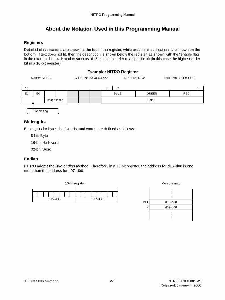
RegistersDetailed classifications are shown at the top of the register, while broader classifications are shown on the bottom. If text does not fit, then the description is shown below the register, as shown with the “enable flag” in the example below. Notation such as “d15” is used to refer to a specific bit (in this case the highest-order bit in a 16-bit register).
Example: NITRO RegisterName: NITRO Address: 0x04000??? Attribute: R/W Initial value: 0x0000
Bit lengthsBit lengths for bytes, half-words, and words are defined as follows:
8-bit: Byte
16-bit: Half-word
32-bit: Word
EndianNITRO adopts the little-endian method. Therefore, in a 16-bit register, the address for d15–d08 is one more than the address for d07–d00.
08 715
E1 E0
Enable flag
Image mode
REDGREENBLUE
Color
d07-d00d15-d08
xx+1
Memory map16-bit register
d15-d08 d07-d00
© 2003-2006 Nintendo xvii NTR-06-0180-001-A9Released: January 4, 2006

NITRO Programming Manual
NTR-06-0180-001-A9 xviii © 2003-2006 NintendoReleased: January 4, 2006
NITRO Programming Manual
1 System
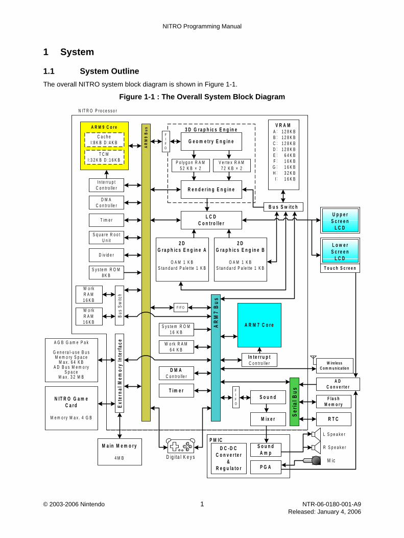
1.1 System OutlineThe overall NITRO system block diagram is shown in Figure 1-1.
Figure 1-1 : The Overall System Block Diagram
2 DG r a p h ic s E n g in e A
O A M 1 K BS ta n d a r d P a le t te 1 K B
L C DC o n t r o l le r
2 DG r a p h ic s E n g in e B
O A M 1 K BS ta n d a r d P a le t te 1 K B
3 D G r a p h ic s E n g in eV R A M
A : 1 2 8 K BB : 1 2 8 K BC : 1 2 8 K BD : 1 2 8 K BE : 6 4 K BF : 1 6 K BG : 1 6 K BH : 3 2 K B
I: 1 6 K B
A R M 9 C o r e
B u s S w it c h
AR
M9
Bus
AR
M7
Bus
A R M 7 C o r e
R e n d e r in g E n g in e
G e o m e t r y E n g in e
P o ly g o n R A M5 2 K B × 2
V e r te x R A M7 2 K B × 2
N IT R O G a m eC a r d
M e m o r y M a x . 4 G B
A G B G a m e P a k
G e n e r a l- u s e B u sM e m o r y S p a c e
M a x . 6 4 K BA D B u s M e m o r y
S p a c eM a x . 3 2 M B
M a in M e m o r y
4 M B
R T C
P M IC
W ire le s sC o m m u n ic a tio n
A DC o n v e r t e r
F la s hM e m o r y
S q u a r e R o o tU n it
D iv id e r
In te r r u p tC o n t r o l le r
D M AC o n tr o l le r
T im e r
S y s te m R O M8 K B
W o r kR A M1 6 K B
S y s te m R O M1 6 K B
W o r k R A M6 4 K B
In t e r r u p tC o n tr o l le r
D M AC o n t r o l le r
T im e rS o u n d
S o u n dA m p
P G A
Bus
Sw
itch
Seria
l Bus
Exte
rnal
Mem
ory
Inte
rfac
e
W o r kR A M1 6 K B
M ix e r
M ic
L S p e a k e r
R S p e a k e r
N IT R O P r o c e s s o r
D C - D CC o n v e r t e r
&R e g u la t o r
FIFO
F IF O
FIFO
C a c h eI :8 K B D :4 K B
T C MI:3 2 K B D :1 6 K B
BAY
X
D ig i ta l K e y s
U p p e rS c r e e n
L C D
T o u c h S c r e e n
L o w e rS c r e e n
L C D
© 2003-2006 Nintendo 1 NTR-06-0180-001-A9Released: January 4, 2006

NITRO Programming Manual
1.1.1 NITRO ProcessorThe NITRO processor is a combined chip that consolidates ARM9 and ARM7 CPU cores with NITRO features and memory for the 2D and 3D graphics engines.
The specifications of the NITRO processor are as follows:
• The CMOS Multi CPU
• Compatibility
Switches between NITRO mode and AGB compatibility mode.
• Graphics Engines
Main processor core ARM946E-S (67.028 MHz)
Subprocessor core ARM7TDMI (33.514 MHz)
2D Graphics Engines A and B 33.514MHz
3D Graphics Engine
Geometry Engine
33.514MHz
Maximum 4 million vertices / second
4 x 4 matrix computation
6-plane clipping
Lighting (4 parallel light sources)
Matrix stack
Texture coordinate conversion
Box culling test
Rendering Engine
33.514MHz
Maximum 120 thousand polygons / second
Maximum 30 million pixels / second
Triangular and quadrilateral rendering
Texture format 4-, 16-, and 256-color palette formats Bitmap format 4 x 4 texel compression formatTranslucent (A3I5, A5I3) format
Texture size8 x 8 to 1024 x1024
Alpha blending
Alpha test
Fog
Toon shading
Edge marking
Anti-aliasing
NTR-06-0180-001-A9 2 © 2003-2006 NintendoReleased: January 4, 2006

NITRO Programming Manual
• Memory
• LCD Controller (built-in for two LCDs: the upper and lower screens)
• Sound
ADPCM/PCM 16 channels (up to 6 channels for the PSG sound source and up to 2 channels for noise)
Includes sound capture capabilities (using reverb, etc.).
• Timers
ARM9 : 16-bit timer x 4
ARM7 : 16-bit timer x 4
• DMA
ARM9 : 4 channel
ARM7 : 4 channel + Sound DMA features
• Accelerator
Divider
Square root unit
• External Memory Interface
DS Game Card interface, DS accessories interface (AGB compatible)
System ROM ARM9 : 8 KB (2K x 32 bit)ARM7 : 16 KB (4K x 32 bit)
NITRO ProcessorInternal Work RAM
ARM9, ARM7 shared: 32 KB ( 8 K x 32 bit)ARM7 dedicated : 64 KB (16 K x 32 bit)
VRAMTotal of 656 KB(128KB + 128KB + 128KB + 128KB + 64KB + 16KB + 16KB + 32KB + 16KB)
System Clock 33.514 MHz
Display Size 256 x 192 x RGB dots
Display Colors 262,144 colors (R:G:B = 6:6:6)
Dot Clock 5.586 MHz
© 2003-2006 Nintendo 3 NTR-06-0180-001-A9Released: January 4, 2006

NITRO Programming Manual
1.1.2 Main MemoryThe main memory is 4 MB (expanded to 8 MB for NITRO debugging) and is connected to the NITRO processor as an independent chip.
Because the NITRO card bus is not mapped to the CPU address space, applications and data must be executed after loading them into main memory.
The load speed from the NITRO card bus into main memory is approximately 5.96 MB/sec.
The application for ARM9 is transmitted from the NITRO card to main memory by system ROM at startup.
The application for ARM7 is transmitted to the ARM7 exclusive work RAM at startup.
1.1.3 LCDThere are two LCD screens, an upper screen and a lower screen.
An overview of both LCD screen specifications is shown in Table 1-1.
Table 1-1 : An Overview of LCD Screen Specifications
Both LCDs have the same specifications but the directions differ, so the order of RGB pixel arrays differs.
1.1.4 Digital KeysThe digital keys are START, SELECT, the + Keypad, A, B, X, Y, L, and R.
1.1.5 Touch ScreenThe entire lower screen LCD is a resistive membrane touch panel that can obtain dot-unit coordinates.
The Nintendo DS system comes equipped with a standard stylus.
1.1.6 MicrophoneA built-in omnidirectional condenser microphone and a (planned) NITRO-exclusive headset can be used with the console.
Sound input from the microphone can be sampled.
1.1.7 RTCThe RTC handles timekeeping operations.
By means of an alarm feature, the RTC can wake up the DS from Sleep Mode at a specified time.
Features Details
Display Resolution 256 x 192 dots (Ratio 4:3)
Number of Displayable Colors 262,144 colors (RGB=6:6:6)
Screen Size 3 inches
Backlight 40 candelas
NTR-06-0180-001-A9 4 © 2003-2006 NintendoReleased: January 4, 2006
NITRO Programming Manual
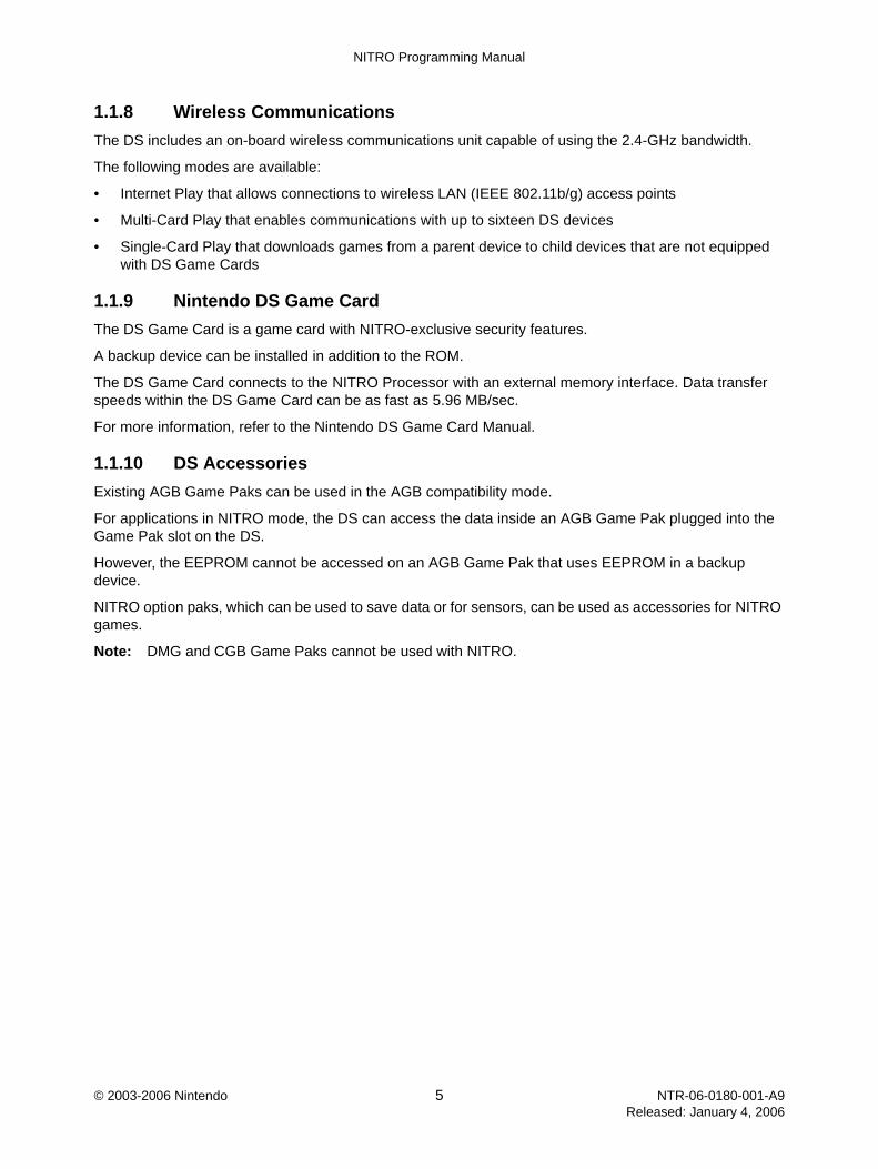
1.1.8 Wireless CommunicationsThe DS includes an on-board wireless communications unit capable of using the 2.4-GHz bandwidth.
The following modes are available:
• Internet Play that allows connections to wireless LAN (IEEE 802.11b/g) access points
• Multi-Card Play that enables communications with up to sixteen DS devices
• Single-Card Play that downloads games from a parent device to child devices that are not equipped with DS Game Cards
1.1.9 Nintendo DS Game CardThe DS Game Card is a game card with NITRO-exclusive security features.
A backup device can be installed in addition to the ROM.
The DS Game Card connects to the NITRO Processor with an external memory interface. Data transfer speeds within the DS Game Card can be as fast as 5.96 MB/sec.
For more information, refer to the Nintendo DS Game Card Manual.
1.1.10 DS AccessoriesExisting AGB Game Paks can be used in the AGB compatibility mode.
For applications in NITRO mode, the DS can access the data inside an AGB Game Pak plugged into the Game Pak slot on the DS.
However, the EEPROM cannot be accessed on an AGB Game Pak that uses EEPROM in a backup device.
NITRO option paks, which can be used to save data or for sensors, can be used as accessories for NITRO games.
Note: DMG and CGB Game Paks cannot be used with NITRO.
© 2003-2006 Nintendo 5 NTR-06-0180-001-A9Released: January 4, 2006

NITRO Programming Manual
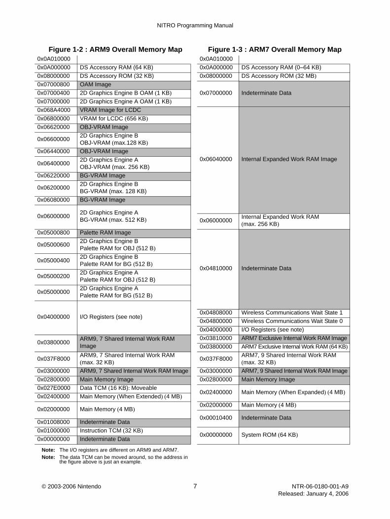
1.2 Memory MapThe overall memory maps for the ARM9 and ARM7 on the DS are shown in Figure 1-2 and Figure 1-3.
The access attributes for the ARM9 memory space are determined by the configuration of the protection units.
For more details, see "3.1 The Protection Unit" on page 35.
• About the image
A decoder converts the address output by the CPU to a memory address.
Because the decoder does not normally decode all the address bits, when an address that is not mounted in memory is accessed, it is converted to the address of the memory located closest to the smallest part of the address. (See the Note below.)
Images are regions of the memory map that appear where nothing normally exists (regions differ from the physical memory).
Even if the address is different on the CPU, the address is the same in memory. Therefore, accessing an image is the same as accessing the physical memory. Furthermore, when the image region is larger than the memory size, an image the same size as the physical memory is repeated.
For example, the BG-VRAM physical memory for 2D Graphics Engine A occupies the 512 kilobytes in the 0x06000000 - 0x0607FFFF section in the Memory Map, but the image region occupies the 1536 KB of the 0x06080000 - 0x061FFFFF section, so there are three images.
Note: For the shared ARM9 and 7 internal Work RAM, the position of the physical memory on the memory map is shifted.
Normally, physical memory begins at 0x03000000. However, when accessing with the memory map address, there is an advantage because the addresses for ARM7 dedicated Work RAM continue from those values.
In addition, there are regions of indeterminate data that have no image (see Figure 1-2 and Figure 1-3).
Note: Do not access the indeterminate data.
NTR-06-0180-001-A9 6 © 2003-2006 NintendoReleased: January 4, 2006
NITRO Programming Manual
Figure 1-2 : ARM9 Overall Memory Map Figure 1-3 : ARM7 Overall Memory Map
Note: The I/O registers are different on ARM9 and ARM7.Note: The data TCM can be moved around, so the address in
the figure above is just an example.
0x0A010000 0x0A0100000x0A000000 DS Accessory RAM (64 KB) 0x0A000000 DS Accessory RAM (0–64 KB)0x08000000 DS Accessory ROM (32 KB) 0x08000000 DS Accessory ROM (32 MB)0x07000800 OAM Image
0x07000000 Indeterminate Data0x07000400 2D Graphics Engine B OAM (1 KB)0x07000000 2D Graphics Engine A OAM (1 KB)0x068A4000 VRAM Image for LCDC
0x06040000 Internal Expanded Work RAM Image
0x06800000 VRAM for LCDC (656 KB)0x06620000 OBJ-VRAM Image
0x06600000 2D Graphics Engine BOBJ-VRAM (max.128 KB)
0x06440000 OBJ-VRAM Image
0x06400000 2D Graphics Engine AOBJ-VRAM (max. 256 KB)
0x06220000 BG-VRAM Image
0x06200000 2D Graphics Engine BBG-VRAM (max. 128 KB)
0x06080000 BG-VRAM Image
0x06000000 2D Graphics Engine ABG-VRAM (max. 512 KB) 0x06000000 Internal Expanded Work RAM
(max. 256 KB)0x05000800 Palette RAM Image
0x04810000 Indeterminate Data
0x05000600 2D Graphics Engine BPalette RAM for OBJ (512 B)
0x05000400 2D Graphics Engine BPalette RAM for BG (512 B)
0x05000200 2D Graphics Engine APalette RAM for OBJ (512 B)
0x05000000 2D Graphics Engine APalette RAM for BG (512 B)
0x04000000 I/O Registers (see note)0x04808000 Wireless Communications Wait State 10x04800000 Wireless Communications Wait State 00x04000000 I/O Registers (see note)
0x03800000 ARM9, 7 Shared Internal Work RAM Image
0x03810000 ARM7 Exclusive Internal Work RAM Image0x03800000 ARM7 Exclusive Internal Work RAM (64 KB)
0x037F8000 ARM9, 7 Shared Internal Work RAM (max. 32 KB) 0x037F8000 ARM7, 9 Shared Internal Work RAM
(max. 32 KB)0x03000000 ARM9, 7 Shared Internal Work RAM Image 0x03000000 ARM7, 9 Shared Internal Work RAM Image0x02800000 Main Memory Image 0x02800000 Main Memory Image0x027E0000 Data TCM (16 KB): Moveable
0x02400000 Main Memory (When Expanded) (4 MB)0x02400000 Main Memory (When Extended) (4 MB)
0x02000000 Main Memory (4 MB)0x02000000 Main Memory (4 MB)
0x00010400 Indeterminate Data0x01008000 Indeterminate Data0x01000000 Instruction TCM (32 KB)
0x00000000 System ROM (64 KB)0x00000000 Indeterminate Data
© 2003-2006 Nintendo 7 NTR-06-0180-001-A9Released: January 4, 2006
NITRO Programming Manual
1.3 Accessing Devices Connected to the SubprocessorOn NITRO, you must use the API to access devices connected to the subprocessor.
By using the API, you can access the device regardless of what state the subprocessor is in.
The following devices connect to the subprocessor: wireless communications, a portion of the digital keys, the sound, Touch Screen, microphone, RTC, and built-in flash memory.
• What is an API?
An Application Program Interface (API) is a group of functions that increase efficiency when developing applications.
In general, the API is used in low-level system calls and to control hardware.
Note: It is possible to access the registers related to the interface with the ARM7 subprocessor in ARM9, but these registers should not be accessed if using the API.
1.4 Startup ModeThe following modes can be selected from the menu that appears after NITRO starts up.
Startup mode is available only from the menu that appears after NITRO starts up.
Startup mode cannot be switched in the application.
1.4.1 NITRO ModeIn this mode, all NITRO features are usable.
1.4.2 AGB Compatibility ModeOf the NITRO processors, the subprocessor starts up at 16.777 MHz as an AGB CPU.
In this mode, the LCD1 screen, the 2D graphics engine, the LCD controller (LCDC), and a part of VRAM are usable, but the ARM9 and ARM9-related peripheral circuitry, the 3D graphics engine, and the serial bus are unusable.
In other words, the features not implemented on the AGB are unusable.
Note: When operating in AGB compatibility mode, the serial bus becomes unusable. Therefore, the wireless communications, Touch Screen, RTC, microphone, and built-in flash memory connected to that bus are also unusable. In addition, the X and Y buttons become unusable.
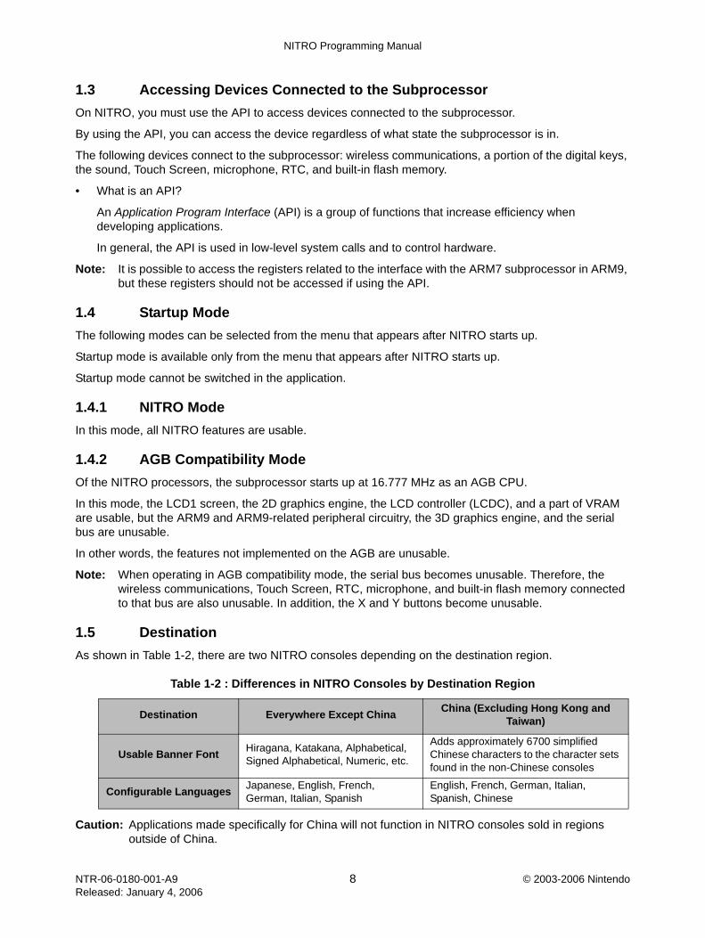
1.5 DestinationAs shown in Table 1-2, there are two NITRO consoles depending on the destination region.
Table 1-2 : Differences in NITRO Consoles by Destination Region
Caution: Applications made specifically for China will not function in NITRO consoles sold in regions outside of China.
Destination Everywhere Except China China (Excluding Hong Kong and Taiwan)
Usable Banner Font Hiragana, Katakana, Alphabetical, Signed Alphabetical, Numeric, etc.
Adds approximately 6700 simplified Chinese characters to the character sets found in the non-Chinese consoles
Configurable Languages Japanese, English, French, German, Italian, Spanish
English, French, German, Italian, Spanish, Chinese
NTR-06-0180-001-A9 8 © 2003-2006 NintendoReleased: January 4, 2006
NITRO Programming Manual
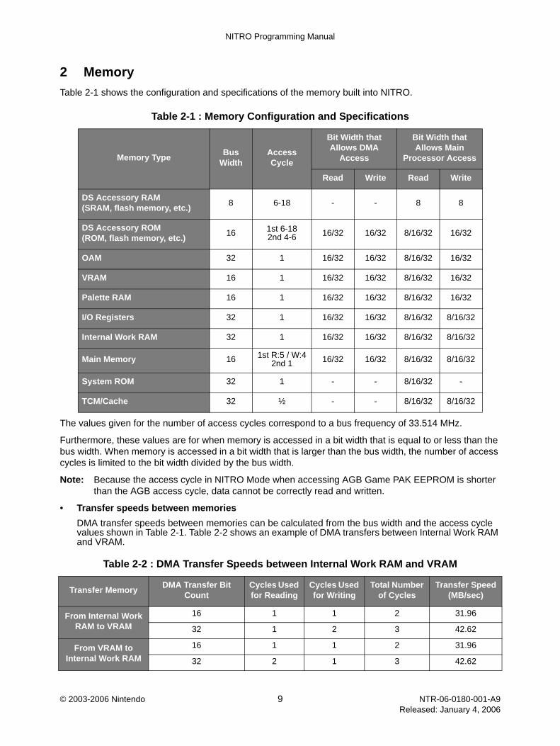
2 MemoryTable 2-1 shows the configuration and specifications of the memory built into NITRO.
Table 2-1 : Memory Configuration and Specifications
The values given for the number of access cycles correspond to a bus frequency of 33.514 MHz.
Furthermore, these values are for when memory is accessed in a bit width that is equal to or less than the bus width. When memory is accessed in a bit width that is larger than the bus width, the number of access cycles is limited to the bit width divided by the bus width.
Note: Because the access cycle in NITRO Mode when accessing AGB Game PAK EEPROM is shorter than the AGB access cycle, data cannot be correctly read and written.
• Transfer speeds between memoriesDMA transfer speeds between memories can be calculated from the bus width and the access cycle values shown in Table 2-1. Table 2-2 shows an example of DMA transfers between Internal Work RAM and VRAM.
Table 2-2 : DMA Transfer Speeds between Internal Work RAM and VRAM
Memory Type Bus Width
Access Cycle
Bit Width that Allows DMA
Access
Bit Width that Allows Main
Processor Access
Read Write Read Write
DS Accessory RAM(SRAM, flash memory, etc.) 8 6-18 - - 8 8
DS Accessory ROM(ROM, flash memory, etc.) 16 1st 6-18
2nd 4-6 16/32 16/32 8/16/32 16/32
OAM 32 1 16/32 16/32 8/16/32 16/32
VRAM 16 1 16/32 16/32 8/16/32 16/32
Palette RAM 16 1 16/32 16/32 8/16/32 16/32
I/O Registers 32 1 16/32 16/32 8/16/32 8/16/32
Internal Work RAM 32 1 16/32 16/32 8/16/32 8/16/32
Main Memory 16 1st R:5 / W:42nd 1 16/32 16/32 8/16/32 8/16/32
System ROM 32 1 - - 8/16/32 -
TCM/Cache 32 ½ - - 8/16/32 8/16/32
Transfer Memory DMA Transfer Bit Count
Cycles Used for Reading
Cycles Used for Writing
Total Number of Cycles
Transfer Speed(MB/sec)
From Internal Work RAM to VRAM
16 1 1 2 31.96
32 1 2 3 42.62
From VRAM to Internal Work RAM
16 1 1 2 31.96
32 2 1 3 42.62
© 2003-2006 Nintendo 9 NTR-06-0180-001-A9Released: January 4, 2006

NITRO Programming Manual
• Main memory transfer speedsMain memory can function as a look-ahead buffer by setting DMA for reading as shown in Table 2-3.
Table 2-3 : DMA settings to function as look-ahead buffer
Capable of holding 16 bits, the look-ahead buffer reads from main memory while data is being written to the destination memory.Table 2-4 and Table 2-5 show the DMA transfer speeds between main memory and internal Work RAM, and between main memory and VRAM. The asterisk symbol (*) denotes a shortening of the total number of cycles due to the look-ahead buffer. For more details about the look-ahead buffer, see "2.1.1 Main Memory" on page 13.
Table 2-4 : DMA transfer speeds between Main Memory and internal Work RAM
Table 2-5 : DMA transfer speeds between Main Memory and VRAM
Transfer speeds by the CPU tend to be slower than calculated because the actual transfer speed is related to the time it takes to execute commands and get to the bus.
Property to Set Set Value
Transfer Bit Count 32 bits
How to Update Source Address Increment
Destination Address Not main memory
Transfer MemoryDMA
Transfer Bit Count
Cycles Used for Reading
Cycles Used for Writing
Total Number of
Cycles
Transfer Speed(MB/sec)
From Main Memory to Internal Work RAM
16 1st 52nd- 1 1 1st 6
2nd- 2 2nd- 31.96
32 1st 62nd- 2 1 1st 7
* 2nd- 2 2nd- 63.92
From Internal Work RAM to Main Memory
16 1 1st 42nd- 1
1st 52nd- 2
2nd- 31.96
32 1 1st 52nd- 2
1st 62nd- 3 2nd- 42.62
Transfer MemoryDMA
Transfer Bit Count
Cycles Used for Reading
Cycles Used for Writing
Total Number of Cycles
Transfer Speed(MB/sec)
From Main Memory to VRAM
16 1st 52nd- 1 1 1st 6
2nd- 2 2nd- 31.96
32 1st 62nd- 2 2 1st 8
* 2nd- 3 2nd- 42.62
From VRAM to Main Memory
16 1 1st 42nd- 1
1st 52nd- 2 2nd- 21.31
32 2 1st 52nd- 2
1st 72nd- 4 2nd- 21.31
NTR-06-0180-001-A9 10 © 2003-2006 NintendoReleased: January 4, 2006
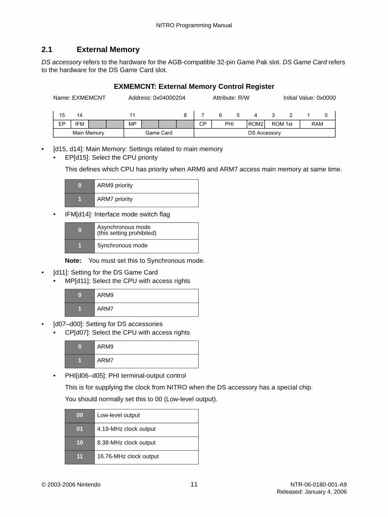
NITRO Programming Manual
2.1 External MemoryDS accessory refers to the hardware for the AGB-compatible 32-pin Game Pak slot. DS Game Card refers to the hardware for the DS Game Card slot.
EXMEMCNT: External Memory Control RegisterName: EXMEMCNT Address: 0x04000204 Attribute: R/W Initial Value: 0x0000
• [d15, d14]: Main Memory: Settings related to main memory• EP[d15]: Select the CPU priority
This defines which CPU has priority when ARM9 and ARM7 access main memory at same time.
• IFM[d14]: Interface mode switch flag
Note: You must set this to Synchronous mode.
• [d11]: Setting for the DS Game Card• MP[d11]: Select the CPU with access rights
• [d07–d00]: Setting for DS accessories• CP[d07]: Select the CPU with access rights
• PHI[d06–d05]: PHI terminal-output control
This is for supplying the clock from NITRO when the DS accessory has a special chip.
You should normally set this to 00 (Low-level output).
0 ARM9 priority
1 ARM7 priority
0 Asynchronous mode(this setting prohibited)
1 Synchronous mode
0 ARM9
1 ARM7
0 ARM9
1 ARM7
00 Low-level output
01 4.19-MHz clock output
10 8.38-MHz clock output
11 16.76-MHz clock output
EP IFM MP CP PHI ROM2 ROM 1st RAMMain Memory Game Card DS Accessory
15 14 11 8 7 6 5 4 3 2 1 0
© 2003-2006 Nintendo 11 NTR-06-0180-001-A9Released: January 4, 2006
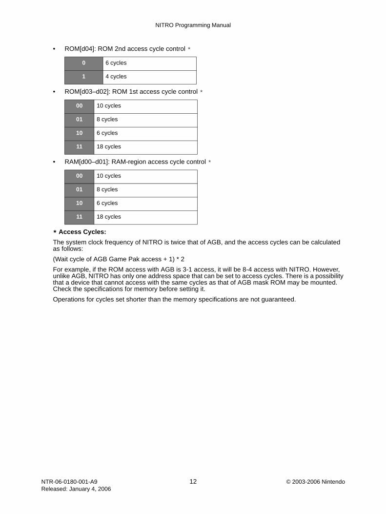
NITRO Programming Manual
• ROM[d04]: ROM 2nd access cycle control *
• ROM[d03–d02]: ROM 1st access cycle control *
• RAM[d00–d01]: RAM-region access cycle control *
* Access Cycles:The system clock frequency of NITRO is twice that of AGB, and the access cycles can be calculated as follows:(Wait cycle of AGB Game Pak access + 1) * 2For example, if the ROM access with AGB is 3-1 access, it will be 8-4 access with NITRO. However, unlike AGB, NITRO has only one address space that can be set to access cycles. There is a possibility that a device that cannot access with the same cycles as that of AGB mask ROM may be mounted. Check the specifications for memory before setting it.Operations for cycles set shorter than the memory specifications are not guaranteed.
0 6 cycles
1 4 cycles
00 10 cycles
01 8 cycles
10 6 cycles
11 18 cycles
00 10 cycles
01 8 cycles
10 6 cycles
11 18 cycles
NTR-06-0180-001-A9 12 © 2003-2006 NintendoReleased: January 4, 2006

NITRO Programming Manual
2.1.1 Main Memory
2.1.1.1 Look-Ahead BufferA look-ahead buffer is implemented as the interface to main memory. This look-ahead buffer is shared by ARM9 DMA and ARM7 DMA.
When a 32-bit DMA transfer is conducted from a source address in main memory to a destination address other than main memory, the write time to the destination address is used to read the next data in 16-bit units. This method enables 32-bit reads to be conducted in a single read cycle.
Note that the look-ahead buffer cannot be used for other types of access, such as reading by the CPU or a 16-bit DMA transfer.
2.1.1.2 Burst ModeIn Burst mode, the sequential access of half-word (16-bit width) is conducted in one cycle.
Table 2-6 shows the basic access cycles for random access and sequential access in Burst mode.
Table 2-6 : Basic access cycles
2.1.1.2.1 Burst Access Conditions
In Burst Mode, sequential access is called Burst Access.
Burst Access is used during DMA transfer when either the source or destination address is the main memory and the address update method for main memory is set to increment.
Because DMA transfers from main memory to main memory are all first accesses, routing through internal RAM provides fast transfer speeds.
In addition, burst access is also used when continuous transfers using LDM or STM instructions are executed.
2.1.1.2.2 Conditions for Inserting WaitsWhen a span of 236 half-words occurs, a wait of three cycles, called a termination, is inserted.
When the address is defined from 0 in units of 16 half-words, waits are also inserted if access starts from address 13, 14, or 15, as shown in Table 2-7 (a maximum of 3 waits are inserted). Processes are thus more efficient if data are located from a 4 half-word boundary (8-byte boundary).
Table 2-7 : Inserting waits according to the access start address
Read Write
Random 5 cycles 4 cycles
Sequential 1 cycle 1 cycle
First Cycle 2 3 4 5 6 7 8 9 ...
13 14 15 wait 16 17 18 19 20 ...
14 15 wait wait 16 17 18 19 20 ...
15 wait wait wait 16 17 18 19 20 ...
© 2003-2006 Nintendo 13 NTR-06-0180-001-A9Released: January 4, 2006

NITRO Programming Manual
2.1.1.2.3 Main Memory DMA Transfer Cycles
2.1.1.2.3.1 32-Bit DMA Transfer Cycle from Main Memory to Work RAM
Because main memory has a 16-bit bus and Work RAM has a 32-bit bus, data read in half-word units is written in word units. While writing in word units, the look-ahead buffer reads more half-word data. Transfers to the geometry command FIFO are the same as transfers to Work RAM.
• Basic CyclesFigure 2-1 shows the basic cycles of the transfer sequence from main memory to Work RAM.
Figure 2-1 : Transfer Sequence from Main Memory to Work RAM (Basic Cycles)
• Worst CaseDepending on the main memory address where access starts, a wait known as a termination may occur. In these cases, the access immediately after the termination becomes the first access.Figure 2-2 shows the worst-case transfer sequence from main memory to Work RAM.
Figure 2-2 : Transfer Sequence from Main Memory to Work RAM (Worst Case)
Cycles 1 2 3 4 5 6 7 8 9 10 11 12 13
WorkRAM 1W 2W 3W 4W
Main Memory wait wait wait wait 1LR 1HR 2LR 2HR 3LR 3HR 4LR 4HR 5LR
... 475 476 477 478 479 480 481 482 483 484 485 486 487
... 236W 237W 238W 239W
... 236LR 236HR T T T 237LR 237HR 238LR 238HR 239LR 239HR 240LR 240HR
Cycles 1 2 3 4 5 6 7 8 9 10 11 12 13
WorkRAM 1W
Main Memory wait wait wait wait 1LR 1HR T T T wait wait wait wait
14 15 16 17 18 19 20 21 22 23 24 25 26
2W 3W 4W 5W 6W 7W
2LR 2HR 3LR 3HR 4LR 4HR 5LR 5HR 6LR 6HR 7LR 7HR 8LR
wait Wait
T Termination
nLR Reads the lower 16 bits of the nth 32-bit data
nHR Reads the upper 16 bits of the nth 32-bit data
nW Writes the nth 32-bit data
NTR-06-0180-001-A9 14 © 2003-2006 NintendoReleased: January 4, 2006
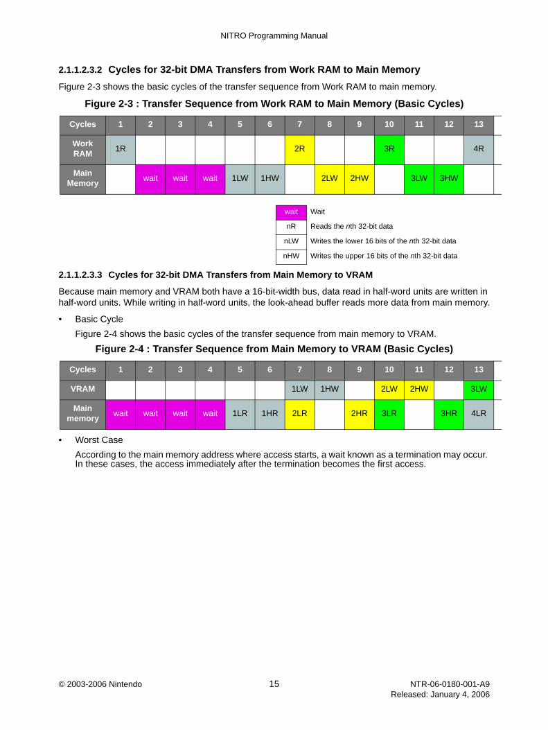
NITRO Programming Manual
2.1.1.2.3.2 Cycles for 32-bit DMA Transfers from Work RAM to Main MemoryFigure 2-3 shows the basic cycles of the transfer sequence from Work RAM to main memory.
Figure 2-3 : Transfer Sequence from Work RAM to Main Memory (Basic Cycles)
2.1.1.2.3.3 Cycles for 32-bit DMA Transfers from Main Memory to VRAM
Because main memory and VRAM both have a 16-bit-width bus, data read in half-word units are written in half-word units. While writing in half-word units, the look-ahead buffer reads more data from main memory.
• Basic CycleFigure 2-4 shows the basic cycles of the transfer sequence from main memory to VRAM.
Figure 2-4 : Transfer Sequence from Main Memory to VRAM (Basic Cycles)
• Worst CaseAccording to the main memory address where access starts, a wait known as a termination may occur. In these cases, the access immediately after the termination becomes the first access.
Cycles 1 2 3 4 5 6 7 8 9 10 11 12 13
WorkRAM 1R 2R 3R 4R
Main Memory wait wait wait 1LW 1HW 2LW 2HW 3LW 3HW
wait Wait
nR Reads the nth 32-bit data
nLW Writes the lower 16 bits of the nth 32-bit data
nHW Writes the upper 16 bits of the nth 32-bit data
Cycles 1 2 3 4 5 6 7 8 9 10 11 12 13
VRAM 1LW 1HW 2LW 2HW 3LW
Main memory wait wait wait wait 1LR 1HR 2LR 2HR 3LR 3HR 4LR
© 2003-2006 Nintendo 15 NTR-06-0180-001-A9Released: January 4, 2006
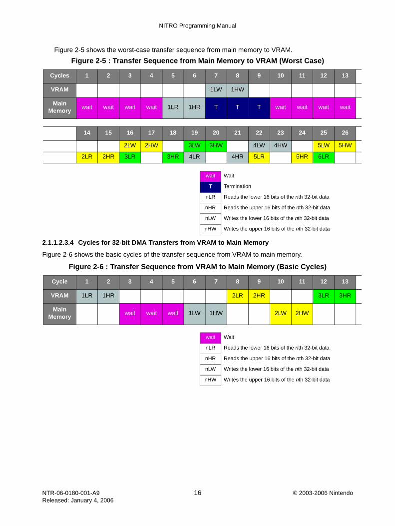
NITRO Programming Manual
Figure 2-5 shows the worst-case transfer sequence from main memory to VRAM.
Figure 2-5 : Transfer Sequence from Main Memory to VRAM (Worst Case)
2.1.1.2.3.4 Cycles for 32-bit DMA Transfers from VRAM to Main Memory
Figure 2-6 shows the basic cycles of the transfer sequence from VRAM to main memory.
Figure 2-6 : Transfer Sequence from VRAM to Main Memory (Basic Cycles)
Cycles 1 2 3 4 5 6 7 8 9 10 11 12 13
VRAM 1LW 1HW
Main Memory wait wait wait wait 1LR 1HR T T T wait wait wait wait
14 15 16 17 18 19 20 21 22 23 24 25 26
2LW 2HW 3LW 3HW 4LW 4HW 5LW 5HW
2LR 2HR 3LR 3HR 4LR 4HR 5LR 5HR 6LR
wait Wait
T Termination
nLR Reads the lower 16 bits of the nth 32-bit data
nHR Reads the upper 16 bits of the nth 32-bit data
nLW Writes the lower 16 bits of the nth 32-bit data
nHW Writes the upper 16 bits of the nth 32-bit data
Cycle 1 2 3 4 5 6 7 8 9 10 11 12 13
VRAM 1LR 1HR 2LR 2HR 3LR 3HR
Main Memory wait wait wait 1LW 1HW 2LW 2HW
wait Wait
nLR Reads the lower 16 bits of the nth 32-bit data
nHR Reads the upper 16 bits of the nth 32-bit data
nLW Writes the lower 16 bits of the nth 32-bit data
nHW Writes the upper 16 bits of the nth 32-bit data
NTR-06-0180-001-A9 16 © 2003-2006 NintendoReleased: January 4, 2006

NITRO Programming Manual
2.2 The NITRO Processor's Internal Memory
2.2.1 VRAMVRAM (A to I) does not have a fixed use, so it can be assigned for each application in the ways that make the most efficient use of memory resources. This ability is called VRAM bank control. Do not switch banks during access to VRAM.
Table 2-8 shows the options for VRAM use.
Table 2-8 : Options for VRAM Use
Memory assigned to LCDC, ARM7, BG-VRAM, and OBJ-VRAM is also mapped to the ARM9 bus, enabling memory to be read and written by ARM9. Memory assigned to the extended palette and texture slots is not mapped to the ARM9 bus.
Note 1: LCDC: The LCD controller (LCDC) handles this region. VRAM A to D can be used as memory for holding bitmap data during VRAM display mode and it can also be set as memory for writing bit-map data during captures. (For details, see "4.4.4.2 VRAM Display Mode" on page 63 and "4.5 Display Capture" on page 67.)
VRAM
Use KB
A B C D E F G H I
128 128 128 128 64 16 16 32 16
LCDC X X X X X X X X X
ARM7 X X
2D Graphics Engine A
BG-VRAM X X X X X X X
OBJ-VRAM X X X X X
BG Extended Palette Slot X X X
OBJ Extended Palette Slot X X
2D Graphics Engine B
BG-VRAM X X X
OBJ-VRAM X X
BG Extended Palette Slot X
OBJ Extended Palette Slot X
3D Graphics (Rendering
Engine)
Texture Image Slot X X X X
Texture Palette Slot X X X
(BG is screen data or character data. OBJ is character data.)
© 2003-2006 Nintendo 17 NTR-06-0180-001-A9Released: January 4, 2006
NITRO Programming Manual
VRAM assigned to LCDC is uniquely mapped to the ARM9 bus. (When all A-to-I of VRAM is assigned to LCDC, it is mapped in a contiguous region of the ARM9 bus.) Because there is no access from the CPU when VRAM is allocated to the Extended Palette slot or the Texture Image/Palette slot, you need to temporarily set data in LCDC to write data.
Note 2: BG-VRAM: This region stores BG screen data, character data, and bitmap data. Up to 512 KB for 2D Graphics Engine A or up to 128 KB for 2D Graphics Engine B can be assigned for this purpose.
Note 3: OBJ-VRAM: This region stores OBJ character data and bitmap data. Up to 256 KB for 2D Graph-ics Engine A or up to 128 KB for 2D Graphics Engine B can be assigned for this purpose.
Note 4: Extended palette slots: This memory space is the property of the 2D graphics engine, which refer-ence color data when BG and OBJ are displayed. The slots are not mapped in the CPU's memory space.
Note 5: Texture image slot and texture palette slot: This memory space is the property of the rendering engine inside the 3D graphics engine. The rendering engine references texel colors when textures are blended. The slots are not mapped in the CPU's memory space.
NTR-06-0180-001-A9 18 © 2003-2006 NintendoReleased: January 4, 2006

NITRO Programming Manual
VRAMCNT: RAM Bank Control Register 0Name: VRAMCNT Address: 0x04000240 Attribute: W Initial Value: 0x00000000
• VRAM-D, VRAM-C• E[d31][d23] Enable flag
• OFS[d28–d27][d20–d19]: Allocated addresses (Allocated to the addresses shown below according to the MST: Allocation options)
1. When MST = 000
Allocated to LCDC, and also mapped to ARM9 memory space
2. When MST = 001
Allocated to 2D Graphics Engine A's BG, and also mapped to ARM9 memory space
3. When MST = 010
Mapped to ARM7 memory space, so not mapped to ARM9 memory space
0 Disable
1 Enable
VRAM-C 0x06840000-0x0685FFFF
VRAM-D 0x06860000-0x0687FFFF
00 0x06000000-0x0601FFFF
01 0x06020000-0x0603FFFF
10 0x06040000-0x0605FFFF
11 0x06060000-0x0607FFFF
00 0x06000000-0x0601FFFF
01 0x06020000-0x0603FFFF
10 Setting prohibited
11 Setting prohibited
E OFS MST E OFS MST E OFS MST E OFS MST
VRAM-D VRAM-C VRAM-B VRAM-A
31 28 27 26 24 23 20 19 18 16 15 12 11 9 8 7 4 3 1 0
© 2003-2006 Nintendo 19 NTR-06-0180-001-A9Released: January 4, 2006

NITRO Programming Manual
4. When MST = 011
Allocated to texture image slot, but not mapped to ARM9 memory space.
(See the texture image slot memory map in Figure 2-7.)
5. When MST = 100
Mapped to the following ARM9 memory spaces, no matter what the setting.
• MST[d26–d24][d18–d16]: Allocation options
Note: Although VRAM-C and VRAM-D can be allocated to the ARM7 subprocessor, to ensure that the subprocessor API operates correctly, do not change the register settings.
• VRAM-B, VRAM-A• E[d15][d07]: Enable flag
• OFS[d12–d11][d04–d03]: Allocated addresses (Allocated to the addresses shown below according to the MST: Allocation options)
1. When MST = 00
Allocated to LCDC and also mapped to ARM9 memory space
00 Texture image slot 0
01 Texture image slot 1
10 Texture image slot 2 (clear color image)
11 Texture image slot 3 (clear depth image)
VRAM-C 0x06200000-0x0621FFFF
VRAM-D 0x06600000-0x0661FFFF
000 Allocate to LCDC
001 Allocate to 2D Graphic Engine A's BG
010 Allocate to ARM7
011 Allocate to 3D rendering engine's texture image
100 For VRAM-C: Allocate to 2D Graphic Engine B's BGFor VRAM-D: Allocate to 2D Graphic Engine B's OBJ
101-111 Setting prohibited
0 Disable
1 Enable
VRAM-A 0x06800000-0x0681FFFF
VRAM-B 0x06820000-0x0683FFFF
NTR-06-0180-001-A9 20 © 2003-2006 NintendoReleased: January 4, 2006
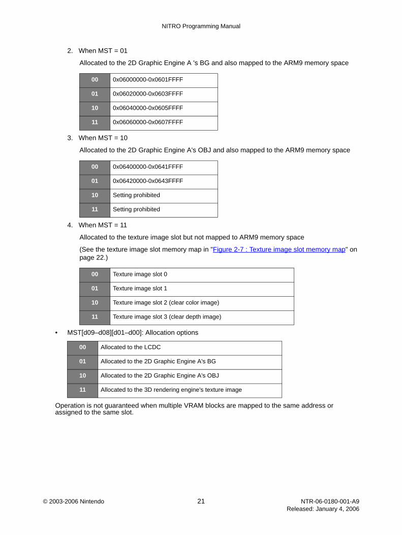
NITRO Programming Manual
2. When MST = 01
Allocated to the 2D Graphic Engine A 's BG and also mapped to the ARM9 memory space
3. When MST = 10
Allocated to the 2D Graphic Engine A's OBJ and also mapped to the ARM9 memory space
4. When MST = 11
Allocated to the texture image slot but not mapped to ARM9 memory space
(See the texture image slot memory map in "Figure 2-7 : Texture image slot memory map" on page 22.)
• MST[d09–d08][d01–d00]: Allocation options
Operation is not guaranteed when multiple VRAM blocks are mapped to the same address or assigned to the same slot.
00 0x06000000-0x0601FFFF
01 0x06020000-0x0603FFFF
10 0x06040000-0x0605FFFF
11 0x06060000-0x0607FFFF
00 0x06400000-0x0641FFFF
01 0x06420000-0x0643FFFF
10 Setting prohibited
11 Setting prohibited
00 Texture image slot 0
01 Texture image slot 1
10 Texture image slot 2 (clear color image)
11 Texture image slot 3 (clear depth image)
00 Allocated to the LCDC
01 Allocated to the 2D Graphic Engine A's BG
10 Allocated to the 2D Graphic Engine A's OBJ
11 Allocated to the 3D rendering engine's texture image
© 2003-2006 Nintendo 21 NTR-06-0180-001-A9Released: January 4, 2006

NITRO Programming Manual
Texture image slots are memory-mapped in the rendering engine as in Figure 2-7.
Figure 2-7 : Texture image slot memory map
Texture image Slot 2 and Slot 3 also works as a clear image buffer to initialize the rendering buffer. (Read about initializing with a clear image in "6.3.3 Initializing the Rendering Buffers" on page 229).
0x00080000
0x00060000Slot 3
(clear depth image)
0x00040000Slot 2
(clear color image)
0x00020000 Slot 1
0x00000000 Slot 0
NTR-06-0180-001-A9 22 © 2003-2006 NintendoReleased: January 4, 2006

NITRO Programming Manual
WVRAMCNT: RAM Bank Control Register 1Name: WVRAMCNT Address: 0x04000244 Attribute: W Initial value: 0x00000000
• VRAM-G, VRAM-F• E[d23][d15]: Enable flag
• OFS[d20–d19][d12–d11]: Allocated addresses (Allocated to the addresses shown below according to the MST: Allocation options)1. When MST = 000
Allocated to LCDC and also mapped to ARM9 memory space
2. When MST = 001Allocated to the 2D Graphic Engine A's BG and also mapped to ARM9 memory space
3. When MST = 010Allocated to the 2D Graphic Engine A's OBJ and also mapped to ARM9 memory space
0 Disable
1 Enable
VRAM-F 0x06890000-0x06893FFF
VRAM-G 0x06894000-0x06897FFF
00 0x06000000-0x06003FFF
01 0x06004000-0x06007FFF
10 0x06010000-0x06013FFF
11 0x06014000-0x06017FFF
00 0x06400000-0x06403FFF
01 0x06404000-0x06407FFF
10 0x06410000-0x06413FFF
11 0x06414000-0x06417FFF
BANK E OFS MST E OFS MST E MST
WRAM VRAM-G VRAM-F VRAM-E
31 24 23 20 19 18 16 15 12 11 10 8 7 2 0
© 2003-2006 Nintendo 23 NTR-06-0180-001-A9Released: January 4, 2006

NITRO Programming Manual
4. When MST = 011Allocated to the texture palette slot, but not mapped to ARM9 memory space.
(See the texture palette slot memory map in "Figure 2-8 : Texture Palette Slot Memory Map" on page 25)
5. When MST = 100Allocated to the 2D Graphic Engine A's BG extended palette slot, but not mapped to ARM9 memory space.
(See the BG extended palette slot memory map in "Figure 2-9 : BG Extended Palette Slot Memory Map" on page 25)
6. When MST = 101Allocated to the 2D Graphic Engine A's OBJ extended palette slot, but not mapped to ARM9 memory space.
The lower 8 KB are allocated to the slot, but the upper 8 KB are invalidated.
See the OBJ extended palette slot memory map in "Figure 2-10 : OBJ Extended Palette Slot Memory Map" on page 26.
• MST[d18–d16][d10–d08]: Allocation options
00 Texture palette slot 0
01 Texture palette slot 1
10 Texture palette slot 4
11 Texture palette slot 5
00 2D Graphic Engine A BG extended palette slots 0-1
01 2D Graphic Engine A BG extended palette slots 2-3
10 Setting prohibited
11 Setting prohibited
000 Allocated to the LCDC
001 Allocated to the 2D Graphic Engine A's BG
010 Allocated to the 2D Graphic Engine A's OBJ
011 Allocated to the 3D Rendering Engine’s texture palette
100 Allocated to the 2D Graphic Engine A's BG extended palette
101 Allocated to the 2D Graphic Engine A's OBJ extended palette
110, 111 Setting prohibited
NTR-06-0180-001-A9 24 © 2003-2006 NintendoReleased: January 4, 2006
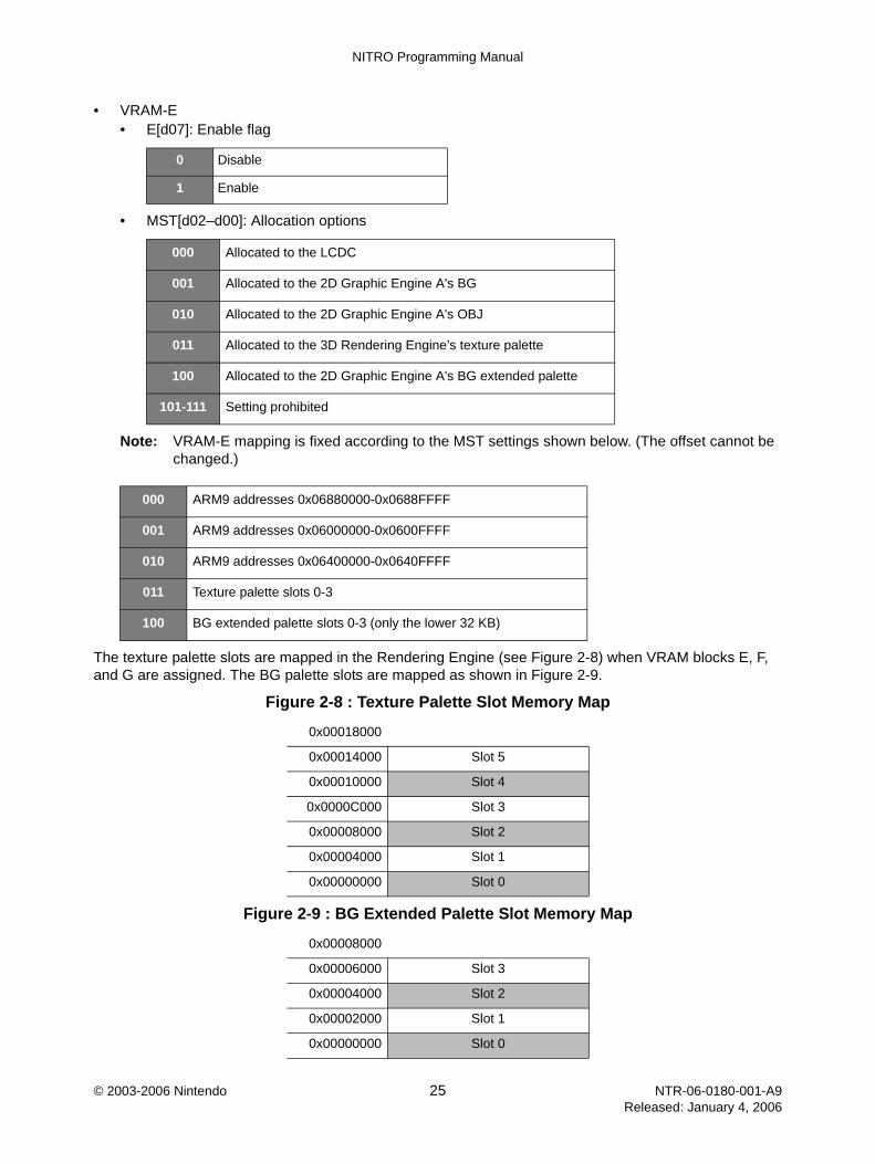
NITRO Programming Manual
• VRAM-E• E[d07]: Enable flag
• MST[d02–d00]: Allocation options
Note: VRAM-E mapping is fixed according to the MST settings shown below. (The offset cannot be changed.)
The texture palette slots are mapped in the Rendering Engine (see Figure 2-8) when VRAM blocks E, F, and G are assigned. The BG palette slots are mapped as shown in Figure 2-9.
Figure 2-8 : Texture Palette Slot Memory Map
Figure 2-9 : BG Extended Palette Slot Memory Map
0 Disable
1 Enable
000 Allocated to the LCDC
001 Allocated to the 2D Graphic Engine A's BG
010 Allocated to the 2D Graphic Engine A's OBJ
011 Allocated to the 3D Rendering Engine’s texture palette
100 Allocated to the 2D Graphic Engine A's BG extended palette
101-111 Setting prohibited
000 ARM9 addresses 0x06880000-0x0688FFFF
001 ARM9 addresses 0x06000000-0x0600FFFF
010 ARM9 addresses 0x06400000-0x0640FFFF
011 Texture palette slots 0-3
100 BG extended palette slots 0-3 (only the lower 32 KB)
0x00018000
0x00014000 Slot 5
0x00010000 Slot 4
0x0000C000 Slot 3
0x00008000 Slot 2
0x00004000 Slot 1
0x00000000 Slot 0
0x00008000
0x00006000 Slot 3
0x00004000 Slot 2
0x00002000 Slot 1
0x00000000 Slot 0
© 2003-2006 Nintendo 25 NTR-06-0180-001-A9Released: January 4, 2006
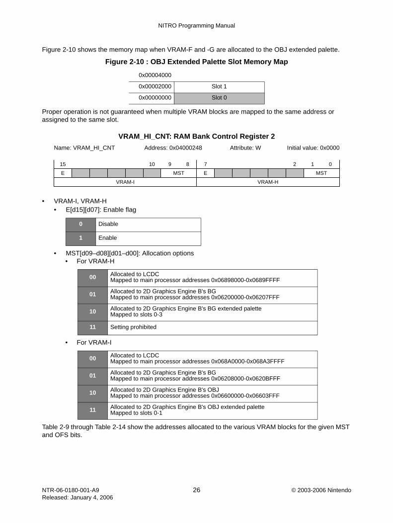
NITRO Programming Manual
Figure 2-10 shows the memory map when VRAM-F and -G are allocated to the OBJ extended palette.
Figure 2-10 : OBJ Extended Palette Slot Memory Map
Proper operation is not guaranteed when multiple VRAM blocks are mapped to the same address or assigned to the same slot.
VRAM_HI_CNT: RAM Bank Control Register 2Name: VRAM_HI_CNT Address: 0x04000248 Attribute: W Initial value: 0x0000
• VRAM-I, VRAM-H• E[d15][d07]: Enable flag
• MST[d09–d08][d01–d00]: Allocation options• For VRAM-H
• For VRAM-I
Table 2-9 through Table 2-14 show the addresses allocated to the various VRAM blocks for the given MST and OFS bits.
0x00004000
0x00002000 Slot 1
0x00000000 Slot 0
0 Disable
1 Enable
00 Allocated to LCDCMapped to main processor addresses 0x06898000-0x0689FFFF
01 Allocated to 2D Graphics Engine B's BGMapped to main processor addresses 0x06200000-0x06207FFF
10 Allocated to 2D Graphics Engine B's BG extended paletteMapped to slots 0-3
11 Setting prohibited
00 Allocated to LCDCMapped to main processor addresses 0x068A0000-0x068A3FFFF
01 Allocated to 2D Graphics Engine B's BGMapped to main processor addresses 0x06208000-0x0620BFFF
10 Allocated to 2D Graphics Engine B's OBJMapped to main processor addresses 0x06600000-0x06603FFF
11 Allocated to 2D Graphics Engine B's OBJ extended paletteMapped to slots 0-1
E MST E MST
VRAM-I VRAM-H
15 8 7 0910 12
NTR-06-0180-001-A9 26 © 2003-2006 NintendoReleased: January 4, 2006

NITRO Programming Manual
Table 2-9 : VRAM-A and VRAM-B Allocations
Table 2-10 : VRAM-C and VRAM-D Allocations
Table 2-11 : VRAM-E Allocations
MST OFSAllocation 00 01 10 11
00 ARM9 VRAM-A: 0x06800000-0x0681FFFFVRAM-B: 0x06820000-0x0683FFFF
01 2D Graphics Engine A
BG-VRAM(0x06000000-0x0601FFFF)
BG-VRAM(0x06020000-0x0603FFFF)
BG-VRAM(0x06040000-0x0605FFFF)
BG-VRAM(0x06060000-0x0607FFFF)
10 2D Graphics Engine A
OBJ-VRAM(0x06400000-0x0641FFFF)
OBJ-VRAM
(0x06420000-0x0643FFFF)
Setting prohibited
11 Texture ImageSlot 0 Slot 1 Slot 2 Slot 3
(clear image)
MST OFSAllocation 00 01 10 11
000 ARM9 VRAM-C: 0x06840000-0x0685FFFFVRAM-D: 0x06860000-0x0687FFFF
001 2D Graphics Engine A
BG-VRAM(0x06000000-0x0601FFFF)
BG-VRAM(0x06020000-0x0603FFFF)
BG-VRAM(0x06040000-0x0605FFFF)
BG-VRAM(0x06060000-0x0607FFFF)
010 ARM7ARM7
0x06000000-0x0601FFFF
ARM70x06020000-0x0603FFFF
Setting prohibited
011 Texture ImageSlot 0 Slot 1 Slot 2 Slot 3
(clear image)
100 2D Graphics Engine B
VRAM-C: BG-VRAM (0x06200000-0x0621FFFF)VRAM-D: OBJ-VRAM (0x06600000-0x0661FFFF)
101-111
Setting Prohibited Setting prohibited
MST Allocation Address
000 ARM9 0x06880000-0x0688FFFF
001 2D Graphics Engine A BG-VRAM (0x06000000-0x0600FFFF)
010 2D Graphics Engine A OBJ-VRAM (0x06400000-0x0640FFFF)
011 Texture Palette Texture palette slot 0-3
100 2D Graphics Engine A BG extended palette slots 0-3 (only the lower 32 KB are valid)
101-111 Setting Prohibited Setting prohibited
© 2003-2006 Nintendo 27 NTR-06-0180-001-A9Released: January 4, 2006
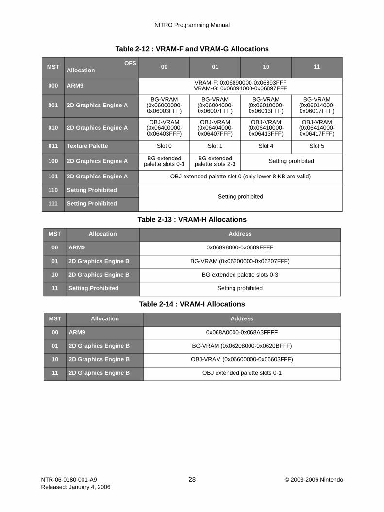
NITRO Programming Manual
Table 2-12 : VRAM-F and VRAM-G Allocations
Table 2-13 : VRAM-H Allocations
Table 2-14 : VRAM-I Allocations
MST OFSAllocation 00 01 10 11
000 ARM9 VRAM-F: 0x06890000-0x06893FFFVRAM-G: 0x06894000-0x06897FFF
001 2D Graphics Engine ABG-VRAM
(0x06000000-0x06003FFF)
BG-VRAM(0x06004000-0x06007FFF)
BG-VRAM(0x06010000-0x06013FFF)
BG-VRAM(0x06014000-0x06017FFF)
010 2D Graphics Engine AOBJ-VRAM
(0x06400000-0x06403FFF)
OBJ-VRAM(0x06404000-0x06407FFF)
OBJ-VRAM(0x06410000-0x06413FFF)
OBJ-VRAM(0x06414000-0x06417FFF)
011 Texture Palette Slot 0 Slot 1 Slot 4 Slot 5
100 2D Graphics Engine A BG extended palette slots 0-1
BG extended palette slots 2-3 Setting prohibited
101 2D Graphics Engine A OBJ extended palette slot 0 (only lower 8 KB are valid)
110 Setting ProhibitedSetting prohibited
111 Setting Prohibited
MST Allocation Address
00 ARM9 0x06898000-0x0689FFFF
01 2D Graphics Engine B BG-VRAM (0x06200000-0x06207FFF)
10 2D Graphics Engine B BG extended palette slots 0-3
11 Setting Prohibited Setting prohibited
MST Allocation Address
00 ARM9 0x068A0000-0x068A3FFFF
01 2D Graphics Engine B BG-VRAM (0x06208000-0x0620BFFF)
10 2D Graphics Engine B OBJ-VRAM (0x06600000-0x06603FFF)
11 2D Graphics Engine B OBJ extended palette slots 0-1
NTR-06-0180-001-A9 28 © 2003-2006 NintendoReleased: January 4, 2006
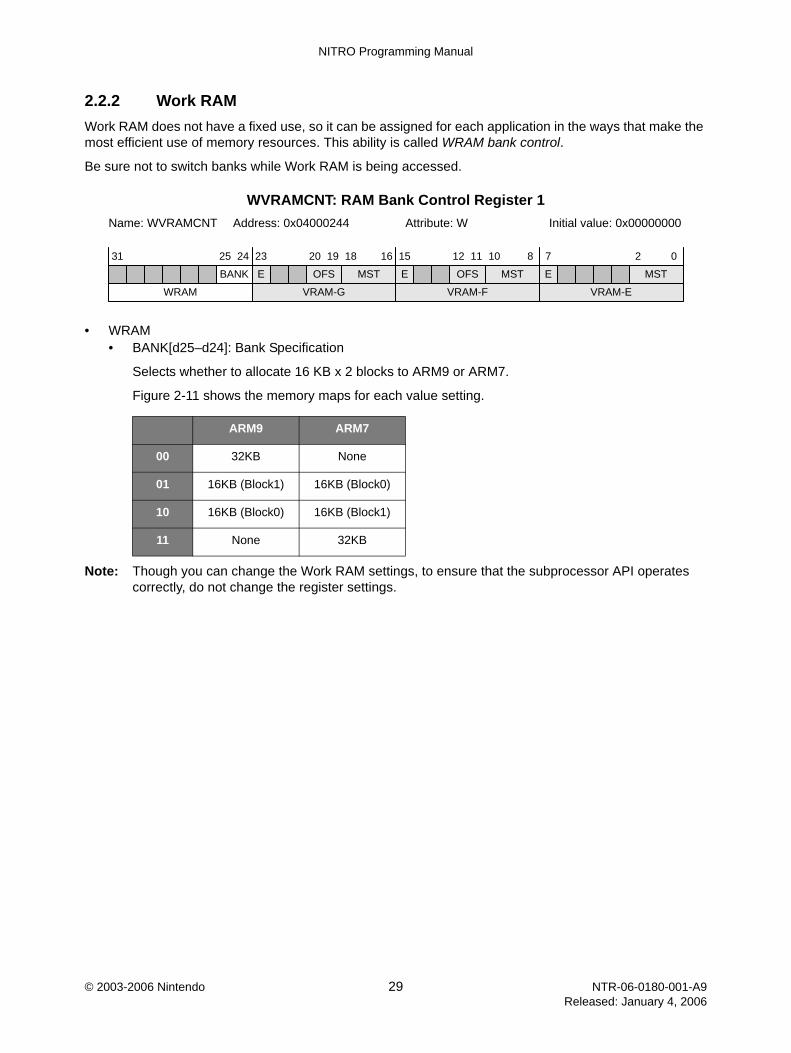
NITRO Programming Manual
2.2.2 Work RAMWork RAM does not have a fixed use, so it can be assigned for each application in the ways that make the most efficient use of memory resources. This ability is called WRAM bank control.
Be sure not to switch banks while Work RAM is being accessed.
WVRAMCNT: RAM Bank Control Register 1Name: WVRAMCNT Address: 0x04000244 Attribute: W Initial value: 0x00000000
• WRAM• BANK[d25–d24]: Bank Specification
Selects whether to allocate 16 KB x 2 blocks to ARM9 or ARM7.
Figure 2-11 shows the memory maps for each value setting.
Note: Though you can change the Work RAM settings, to ensure that the subprocessor API operates correctly, do not change the register settings.
ARM9 ARM7
00 32KB None
01 16KB (Block1) 16KB (Block0)
10 16KB (Block0) 16KB (Block1)
11 None 32KB
BANK E OFS MST E OFS MST E MST
WRAM VRAM-G VRAM-F VRAM-E
31 24 23 20 19 18 16 15 12 11 10 8 7 2 025
© 2003-2006 Nintendo 29 NTR-06-0180-001-A9Released: January 4, 2006
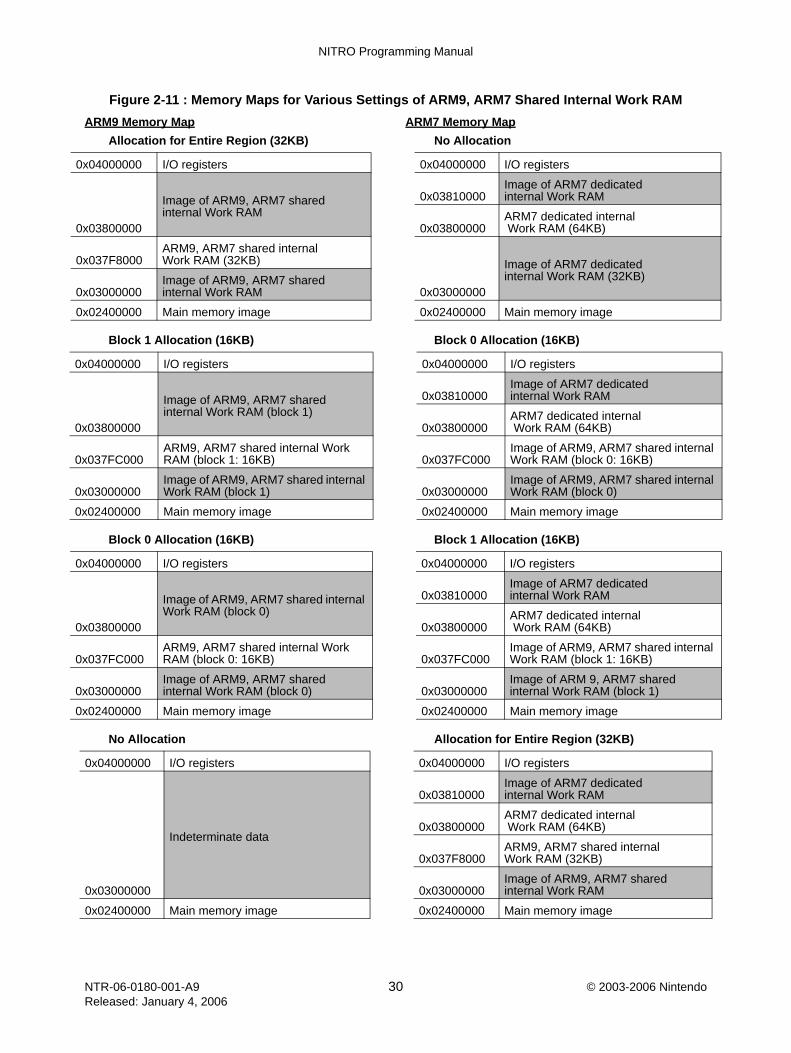
NITRO Programming Manual
Figure 2-11 : Memory Maps for Various Settings of ARM9, ARM7 Shared Internal Work RAMARM9 Memory Map ARM7 Memory Map
Allocation for Entire Region (32KB) No Allocation
Block 1 Allocation (16KB) Block 0 Allocation (16KB)
Block 0 Allocation (16KB) Block 1 Allocation (16KB)
No Allocation Allocation for Entire Region (32KB)
0x04000000 I/O registers 0x04000000 I/O registers
0x03800000
Image of ARM9, ARM7 shared internal Work RAM
0x03810000Image of ARM7 dedicated internal Work RAM
0x03800000ARM7 dedicated internal Work RAM (64KB)
0x037F8000ARM9, ARM7 shared internal Work RAM (32KB)
0x03000000
Image of ARM7 dedicated internal Work RAM (32KB)
0x03000000Image of ARM9, ARM7 shared internal Work RAM
0x02400000 Main memory image 0x02400000 Main memory image
0x04000000 I/O registers 0x04000000 I/O registers
0x03800000
Image of ARM9, ARM7 shared internal Work RAM (block 1)
0x03810000Image of ARM7 dedicated internal Work RAM
0x03800000ARM7 dedicated internal Work RAM (64KB)
0x037FC000ARM9, ARM7 shared internal Work RAM (block 1: 16KB) 0x037FC000
Image of ARM9, ARM7 shared internal Work RAM (block 0: 16KB)
0x03000000Image of ARM9, ARM7 shared internal Work RAM (block 1) 0x03000000
Image of ARM9, ARM7 shared internal Work RAM (block 0)
0x02400000 Main memory image 0x02400000 Main memory image
0x04000000 I/O registers 0x04000000 I/O registers
0x03800000
Image of ARM9, ARM7 shared internal Work RAM (block 0)
0x03810000Image of ARM7 dedicated internal Work RAM
0x03800000ARM7 dedicated internal Work RAM (64KB)
0x037FC000ARM9, ARM7 shared internal Work RAM (block 0: 16KB) 0x037FC000
Image of ARM9, ARM7 shared internal Work RAM (block 1: 16KB)
0x03000000Image of ARM9, ARM7 shared internal Work RAM (block 0) 0x03000000
Image of ARM 9, ARM7 shared internal Work RAM (block 1)
0x02400000 Main memory image 0x02400000 Main memory image
0x04000000 I/O registers 0x04000000 I/O registers
0x03000000
Indeterminate data
0x03810000Image of ARM7 dedicated internal Work RAM
0x03800000ARM7 dedicated internal Work RAM (64KB)
0x037F8000ARM9, ARM7 shared internal Work RAM (32KB)
0x03000000Image of ARM9, ARM7 shared internal Work RAM
0x02400000 Main memory image 0x02400000 Main memory image
NTR-06-0180-001-A9 30 © 2003-2006 NintendoReleased: January 4, 2006
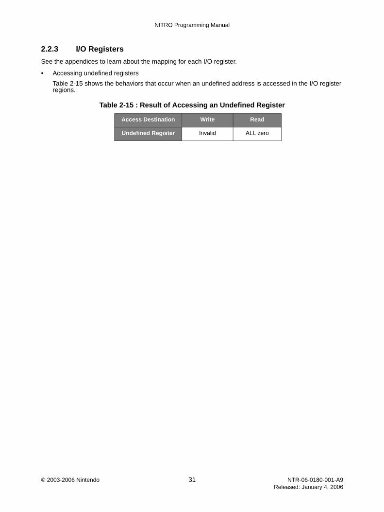
NITRO Programming Manual
2.2.3 I/O RegistersSee the appendices to learn about the mapping for each I/O register.
• Accessing undefined registersTable 2-15 shows the behaviors that occur when an undefined address is accessed in the I/O register regions.
Table 2-15 : Result of Accessing an Undefined Register
Access Destination Write Read
Undefined Register Invalid ALL zero
© 2003-2006 Nintendo 31 NTR-06-0180-001-A9Released: January 4, 2006

NITRO Programming Manual
2.3 Memory Map for Game Card BootFigure 2-12 shows the memory map when the system boots from a Game Card.
Figure 2-12 : Memory Map for Game Card Boot
The following are details about the regions shown in the memory map:
• Resident Module:Loaded at application startup time.
• Overlay Module:Loaded by the application itself.
• Data BinaryLoaded by the application itself.
Not linked; loaded by referencing FAT.
ARM7 ResidentModule
0x0380_F000
0x037F_8000
0x027F_FE000x027F_FF80
0x027F_FC80
0x023F_E000
0x0200_0000
HeaderRegion16 KB
0x0000_4000
0x0000_01800x0000_0000
0x0000_8000
ARM9 ResidentModule
ARM9 OverlayModule 1
ARM9 OverlayModule 2
NITRO Memory Map
Main Memory
Device Map
ROM Registration Data
Non-load Region
ARM7 ResidentModule
SecureRegion16 KB
GameRegion
ROM Image
ARM7 OverlayModule 1
Data Binary 2
…
CPU Internal Work RAM
ARM7 OverlayModule 2
Data Binary 1
…
…
ROM Registration Data
NITRO Setting Data
ARM9 ResidentModuleEncrypted Region 2 KB
Encrypted Region 2 KB
ARM7BootableRegion92 KB
Can load toonly one
ARM9BootableRegion2.5 MB
ARM7BootableRegion256 KBfrom the3.99 MB
0x0228_0000
NTR-06-0180-001-A9 32 © 2003-2006 NintendoReleased: January 4, 2006

NITRO Programming Manual
• The Header Region:Stores the ROM registration data. This data is loaded into the System region of main memory at boot time.Cannot be reloaded after application startup.(After the Game Code is determined) Provides a binary file called a ROM header template for each application.
• The Secure Region:Stores the starting part of the ARM9 Resident Module. This is loaded at boot time to the address in main memory specified by the registration data in ROM.Must be located within the first 64 KB from the start of main memory, for security reasons. Decodes the first 2 KB, an encrypted region, when loaded.
To be specific, the encrypted system call library is linked to the start when the ARM9 resident module is created.
Because this cannot be reloaded after application startup, only the .text and .rodata sections should be located in the secure region. Otherwise, you cannot perform a software reset.
• The Game Region:Loads (at boot time) the part of the ARM9 Resident Module that follows the security region and the ARM7 Resident Module to the address specified by the registration data in ROM.Set the bootable size for ARM9 so that it does not exceed 2.5 MB from the beginning of main memory. For ARM7, the bootable region should not exceed 256 KB within the 3.99 MB region from the beginning of main memory or should not exceed 92 KB from the beginning of the CPU internal work RAM.This region is always read-enabled. Load the Overlay Module and Data Binary as needed with the application.
• The NITRO Settings Data:Contains owner information and other data, stored in internal flash memory.
If this data is available, it is loaded by the IPL to address 0x027F_FC80 at startup.
For details about the data structure, see Chapter "18 Internal Flash Memory" on page 319.
Note: Refer to the Nintendo DS Game Card Manual for the ROM Internal Registration Data.
© 2003-2006 Nintendo 33 NTR-06-0180-001-A9Released: January 4, 2006
NITRO Programming Manual
NTR-06-0180-001-A9 34 © 2003-2006 NintendoReleased: January 4, 2006

NITRO Programming Manual
3 The Main Processor Core (ARM946E-S)Figure 3-1 is a block diagram of the main processor core.
Figure 3-1 : Block Diagram of the Main Processor Core
3.1 The Protection UnitThe Protection Unit protects memory by configuring the read/write attributes and enabling/disabling the use of the cache and Write buffers in each protection region.
Up to eight memory regions can be configured from the 4 GB of background (the entire address space accessible from the CPU). Protection regions with higher region numbers have higher priority. (If regions have duplicate protection region settings, the setting with the higher protection region number is given priority.) Each protection region can be configured separately to enable/disable the cache and Write buffers and allow/disallow reading/writing.
• Debug Version and Release Version
In addition to the production version of NITRO, there is a debug version that comes with the main memory expanded to 8 MB. Though part of the additional 4 MB of main memory is used as the debugger region, the remainder can be used during application development. Because the debug and release versions of NITRO have different memory structures, the Protection Unit settings are also different.
Interface Unit
ARM946E-SCore
Data Cache4KB
Instruction Cache8KB
Write Buffer
DataTCM16KB
Instruction TCM32KB
ARM9 Bus
DMAController
InterruptController
Main ProcessorIRQ
ProtectionUnitProtection Unit
ARM7TDMICore
SubprocessorFIFO External Memory Interface
Main MemoryDS Game CardDS Accessory
© 2003-2006 Nintendo 35 NTR-06-0180-001-A9Released: January 4, 2006
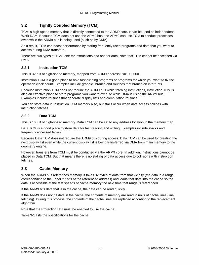
NITRO Programming Manual
3.2 Tightly Coupled Memory (TCM)TCM is high-speed memory that is directly connected to the ARM9 core. It can be used as independent Work RAM. Because TCM does not use the ARM9 bus, the ARM9 can use TCM to conduct processes even while the ARM9 bus is being used (such as by DMA).
As a result, TCM can boost performance by storing frequently used programs and data that you want to access during DMA transfers.
There are two types of TCM: one for instructions and one for data. Note that TCM cannot be accessed via DMA.
3.2.1 Instruction TCMThis is 32 KB of high-speed memory, mapped from ARM9 address 0x01000000.
Instruction TCM is a good place to hold fast-running programs or programs for which you want to fix the operation clock count. Examples include graphic libraries and routines that branch on interrupts.
Because Instruction TCM does not require the ARM9 bus while fetching instructions, Instruction TCM is also an effective place to store programs you want to execute while DMA is using the ARM9 bus. Examples include routines that generate display lists and computation routines.
You can store data in Instruction TCM memory also, but stalls occur when data access collides with instruction fetches.
3.2.2 Data TCMThis is 16 KB of high-speed memory. Data TCM can be set to any address location in the memory map.
Data TCM is a good place to store data for fast reading and writing. Examples include stacks and frequently accessed tables.
Because Data TCM does not require the ARM9 bus during access, Data TCM can be used for creating the next display list even while the current display list is being transferred via DMA from main memory to the geometry engine.
However, transfers from TCM must be conducted via the ARM9 core. In addition, instructions cannot be placed in Data TCM. But that means there is no stalling of data access due to collisions with instruction fetches.
3.3 Cache MemoryWhen the ARM9 bus references memory, it takes 32 bytes of data from that vicinity (the data in a range corresponding to the upper 27 bits of the referenced address) and loads that data into the cache so the data is accessible at the fast speeds of cache memory the next time that range is referenced.
If the ARM9 hits data that is in the cache, the data can be read quickly.
If the ARM9 does not hit data in the cache, the contents of memory are read in units of cache lines (line fetching). During this process, the contents of the cache lines are replaced according to the replacement algorithm.
Note that the Protection Unit must be enabled to use the cache.
Table 3-1 lists the specifications for the cache.
NTR-06-0180-001-A9 36 © 2003-2006 NintendoReleased: January 4, 2006

NITRO Programming Manual
Table 3-1 : Cache Specifications
Note 1: Read-allocate methods
In this method, when there is a write miss, the write is performed only for the memory (or for the Write buffer, if it is enabled). Data is not loaded to the cache. (For the Write-allocation method, a write miss is handled as a write hit after data is loaded into the cache.)
Note 2: Round-robin (recommended)
In this method, cache lines are replaced in order. Performance is stable in the worst-case scenario.
Note 3: Pseudo-random
In this method, cache lines are replaced randomly. This increases peak-time performance, but lowers worst-case performance.
Note 4: Bus Snoop feature
By monitoring the bus, this feature detects whether another processor or DMA writes to the memory region stored in the cache. Because the ARM946E-S does not have this feature, you must be careful that there is coherency between memory and cache. (See "3.5 Ensuring Coherency" on page 43.)
3.3.1 Instruction CacheThis is 8 KB of high-speed memory, dedicated to instruction code.
The ARM9 bus is not used during cache hits, so a program in the Instruction cache can run even when a non-ARM9 bus master (DMA or subprocessor) has possession of the ARM9 bus.
3.3.1.1 Determining Hits and Misses
When the ARM9 bus fetches instruction code from memory, the Instruction Cache Controller extracts the Index bit and TAG bit from the memory addresses and compares the contents of TAG RAM in the nth cache line (defined by the Index number) with the TAG bit at that memory address. Because the ARM946E-S cache has a four-set structure, the comparison is made on four cache lines. If the comparison finds a match for any of these four cache lines, and if the Valid bit flag is enabled, then it is determined that the cache line contains the targeted instruction code (a hit). If not, it is considered a miss.
For a cache hit, the intended instruction code in Data RAM is identified from the address' Word or Byte and can be accessed quickly. For a miss, the cache lines are fetched from memory via the ARM9 bus.
Figure 3-2 shows the structure and actions of the Instruction cache.
Capacity Instruction cache: 8 KBData cache: 4 KB
Configuration 4-way set associative method
Cache Line 8 words (32 bytes)
Write-miss Operation Read-allocate method (see note 1)
Replacement Algorithm
Can choose either round-robin (see note 2) or pseudo-random (see note 3)
Bus Snoop Feature (see note 4) None
Other Features (Instruction Cache)
LockdownInstruction prefetch
Other Features(Data Cache)
LockdownWrite-through mode / Write-back mode
© 2003-2006 Nintendo 37 NTR-06-0180-001-A9Released: January 4, 2006
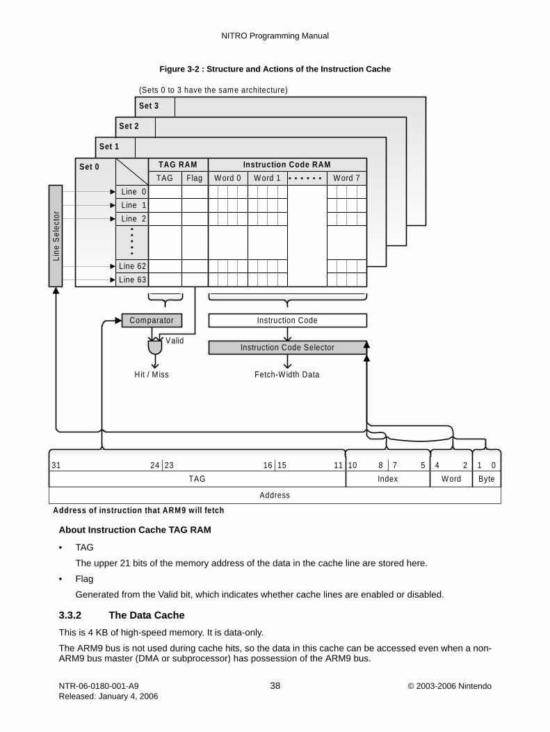
NITRO Programming Manual
Figure 3-2 : Structure and Actions of the Instruction Cache
About Instruction Cache TAG RAM
• TAG
The upper 21 bits of the memory address of the data in the cache line are stored here.
• Flag
Generated from the Valid bit, which indicates whether cache lines are enabled or disabled.
3.3.2 The Data CacheThis is 4 KB of high-speed memory. It is data-only.
The ARM9 bus is not used during cache hits, so the data in this cache can be accessed even when a non-ARM9 bus master (DMA or subprocessor) has possession of the ARM9 bus.
Address
31 24 23 16 15 11 10 8 7 5 4 2 1 0ByteWordIndexTAG
Set 3
Set 2
Set 1
Comparator
Hit / Miss
Instruction Code
Instruction Code Selector
Fetch-Width Data
(Sets 0 to 3 have the same architecture)
Valid
Address of instruction that ARM9 will fetch
Line 0Line 1Line 2
Line 62Line 63
TAG RAMSet 0 Instruction Code RAMTAG Flag Word 1Word 0 Word 7
Line
Sel
ecto
r
NTR-06-0180-001-A9 38 © 2003-2006 NintendoReleased: January 4, 2006
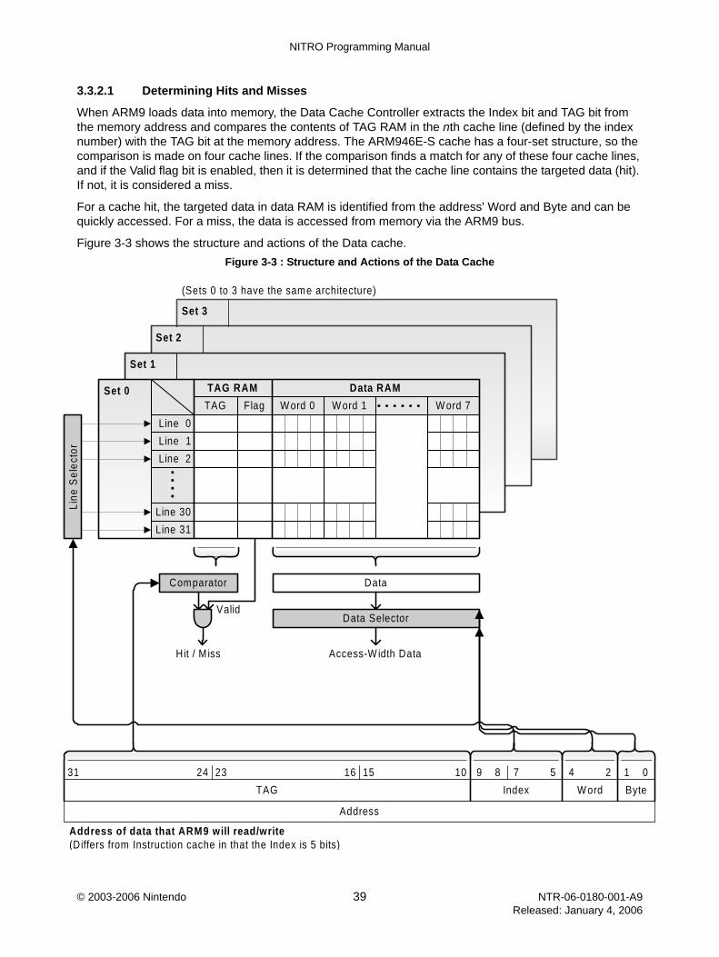
NITRO Programming Manual
3.3.2.1 Determining Hits and Misses
When ARM9 loads data into memory, the Data Cache Controller extracts the Index bit and TAG bit from the memory address and compares the contents of TAG RAM in the nth cache line (defined by the index number) with the TAG bit at the memory address. The ARM946E-S cache has a four-set structure, so the comparison is made on four cache lines. If the comparison finds a match for any of these four cache lines, and if the Valid flag bit is enabled, then it is determined that the cache line contains the targeted data (hit). If not, it is considered a miss.
For a cache hit, the targeted data in data RAM is identified from the address' Word and Byte and can be quickly accessed. For a miss, the data is accessed from memory via the ARM9 bus.
Figure 3-3 shows the structure and actions of the Data cache.Figure 3-3 : Structure and Actions of the Data Cache
Address
31 24 23 16 15 10 9 8 7 5 4 2 1 0ByteWordIndexTAG
Set 3
Set 2
Set 1
Comparator
Hit / M iss
Data
Data Selector
Access-W idth Data
(Sets 0 to 3 have the same architecture)
Valid
Address of data that ARM9 will read/write(Differs from Instruction cache in that the Index is 5 bits)
Line 0Line 1Line 2
Line 30Line 31
TAG RAMSet 0 Data RAMTAG Flag W ord 1W ord 0 W ord 7
Line
Sel
ecto
r
© 2003-2006 Nintendo 39 NTR-06-0180-001-A9Released: January 4, 2006
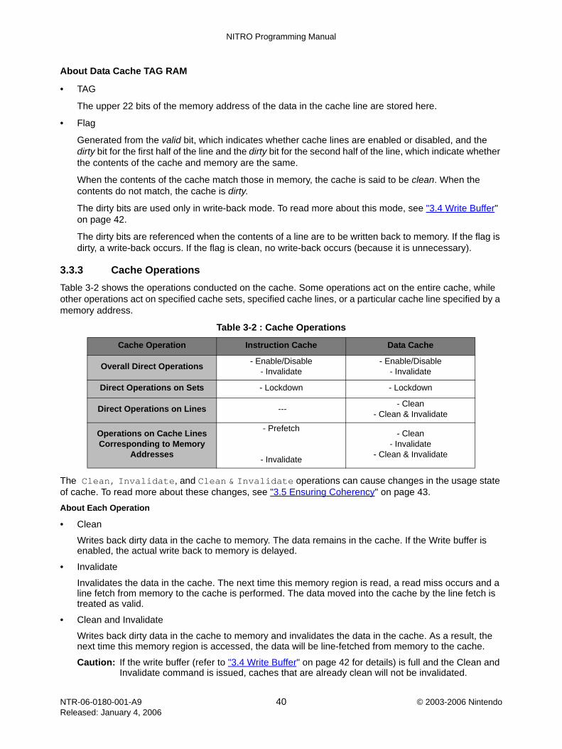
NITRO Programming Manual
About Data Cache TAG RAM
• TAG
The upper 22 bits of the memory address of the data in the cache line are stored here.
• Flag
Generated from the valid bit, which indicates whether cache lines are enabled or disabled, and the dirty bit for the first half of the line and the dirty bit for the second half of the line, which indicate whether the contents of the cache and memory are the same.
When the contents of the cache match those in memory, the cache is said to be clean. When the contents do not match, the cache is dirty.
The dirty bits are used only in write-back mode. To read more about this mode, see "3.4 Write Buffer" on page 42.
The dirty bits are referenced when the contents of a line are to be written back to memory. If the flag is dirty, a write-back occurs. If the flag is clean, no write-back occurs (because it is unnecessary).
3.3.3 Cache OperationsTable 3-2 shows the operations conducted on the cache. Some operations act on the entire cache, while other operations act on specified cache sets, specified cache lines, or a particular cache line specified by a memory address.
Table 3-2 : Cache Operations
The Clean, Invalidate, and Clean & Invalidate operations can cause changes in the usage state of cache. To read more about these changes, see "3.5 Ensuring Coherency" on page 43.About Each Operation
• Clean
Writes back dirty data in the cache to memory. The data remains in the cache. If the Write buffer is enabled, the actual write back to memory is delayed.
• Invalidate
Invalidates the data in the cache. The next time this memory region is read, a read miss occurs and a line fetch from memory to the cache is performed. The data moved into the cache by the line fetch is treated as valid.
• Clean and Invalidate
Writes back dirty data in the cache to memory and invalidates the data in the cache. As a result, the next time this memory region is accessed, the data will be line-fetched from memory to the cache.
Caution: If the write buffer (refer to "3.4 Write Buffer" on page 42 for details) is full and the Clean and Invalidate command is issued, caches that are already clean will not be invalidated.
Cache Operation Instruction Cache Data Cache
Overall Direct Operations - Enable/Disable- Invalidate
- Enable/Disable- Invalidate
Direct Operations on Sets - Lockdown - Lockdown
Direct Operations on Lines --- - Clean- Clean & Invalidate
Operations on Cache Lines Corresponding to Memory
Addresses
- Prefetch
- Invalidate
- Clean- Invalidate
- Clean & Invalidate
NTR-06-0180-001-A9 40 © 2003-2006 NintendoReleased: January 4, 2006

NITRO Programming Manual
• Instruction Prefetch (prefetch)Takes instruction code that has not yet been fetched by the program and preloads it into the Instruction cache. It uses coprocessor instructions.
• LockdownBy locking down one set of cache, no line in that set can be replaced by line fetches and the whole set can be used as a block of Work RAM. However, this reduces the cache region by the same amount and increases the miss rate.
• Enable/DisableWhen using the cache, in addition to enabling the cache, you must also enable the Protection Unit.
You can enable/disable the Instruction cache and the Data cache for each protection region. To read about protection regions and their settings, see "3.1 The Protection Unit" on page 35.
Caution: Data Preload (preload) is a feature that preloads data that has not been accessed by the program and normally operates by using the PLD instruction. However, due to ARM946E-S specifications, no operation will be performed even when a PLD instruction is recognized. Therefore, the data preload feature does not work with ARM946E-S.
3.3.4 Optimizing the CacheThe cache uses the memory reference locality of most programs to accelerate memory access.
Temporal locality The high probability that data, once referenced, will be referenced again soon.
Spatial locality The high probability that data near referenced data will also be referenced.
Programs with a higher reference locality have higher cache hit rates and faster average access speeds.
Depending on how a program is pieced together, you can manually increase the reference locality to some extent. For example, when constructing a loop to handle a two-dimensional (or higher) array, you can boost the spatial locality of the array by handling addresses in consecutive order.
Examples:
In loop example A, the TEST array is referenced every 0x100 addresses inside the loop, so there is no cache hit during the first iteration. Lines are fetched one after another in the first iteration. However, because the capacity of the Data cache is 32 lines x 4 sets for a total of 128 lines (0x80 lines), the entire loop does not fit in the Data cache and hits occur only half the time in the second and subsequent iterations.
In contrast, in loop example B, the TEST array is referenced in the same order as the addresses inside the loop, enabling the maximum hit rate.
Loop Example A Loop Example B
for( j=0; j<0x100; j++) { for( i=0; i<0x100; i++) { RESULT += TEST[i, j];
}}
for( i=0; i<0x100; i++) { for( j=0; j<0x100; j++) { RESULT += TEST[i, j];
}}
© 2003-2006 Nintendo 41 NTR-06-0180-001-A9Released: January 4, 2006
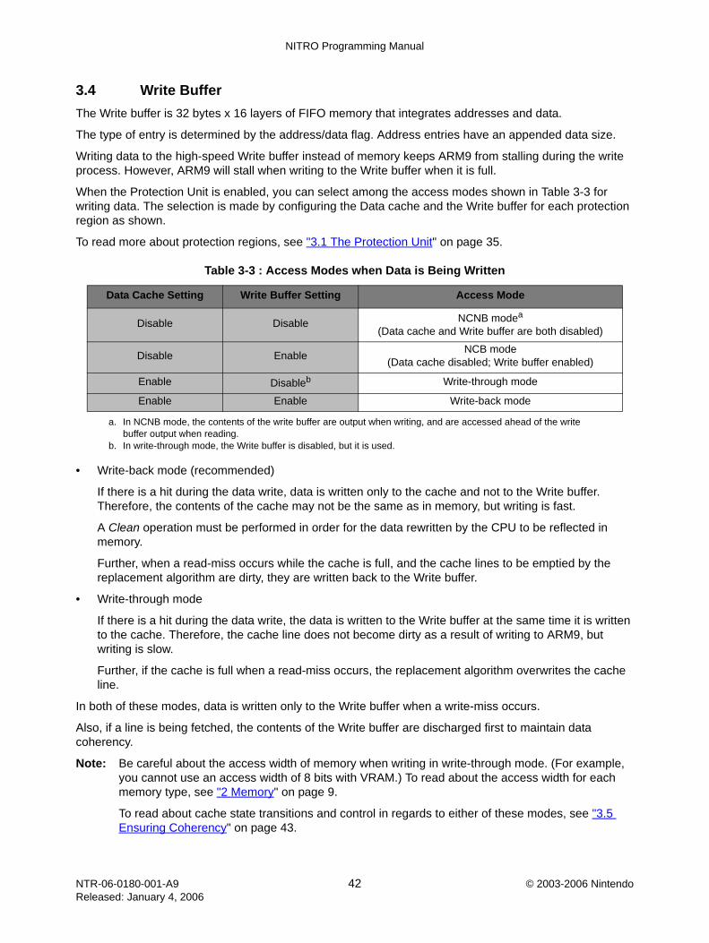
NITRO Programming Manual
3.4 Write BufferThe Write buffer is 32 bytes x 16 layers of FIFO memory that integrates addresses and data.
The type of entry is determined by the address/data flag. Address entries have an appended data size.
Writing data to the high-speed Write buffer instead of memory keeps ARM9 from stalling during the write process. However, ARM9 will stall when writing to the Write buffer when it is full.
When the Protection Unit is enabled, you can select among the access modes shown in Table 3-3 for writing data. The selection is made by configuring the Data cache and the Write buffer for each protection region as shown.
To read more about protection regions, see "3.1 The Protection Unit" on page 35.
Table 3-3 : Access Modes when Data is Being Written
• Write-back mode (recommended)
If there is a hit during the data write, data is written only to the cache and not to the Write buffer. Therefore, the contents of the cache may not be the same as in memory, but writing is fast.
A Clean operation must be performed in order for the data rewritten by the CPU to be reflected in memory.
Further, when a read-miss occurs while the cache is full, and the cache lines to be emptied by the replacement algorithm are dirty, they are written back to the Write buffer.
• Write-through mode
If there is a hit during the data write, the data is written to the Write buffer at the same time it is written to the cache. Therefore, the cache line does not become dirty as a result of writing to ARM9, but writing is slow.
Further, if the cache is full when a read-miss occurs, the replacement algorithm overwrites the cache line.
In both of these modes, data is written only to the Write buffer when a write-miss occurs.
Also, if a line is being fetched, the contents of the Write buffer are discharged first to maintain data coherency.
Note: Be careful about the access width of memory when writing in write-through mode. (For example, you cannot use an access width of 8 bits with VRAM.) To read about the access width for each memory type, see "2 Memory" on page 9.
To read about cache state transitions and control in regards to either of these modes, see "3.5 Ensuring Coherency" on page 43.
Data Cache Setting Write Buffer Setting Access Mode
Disable Disable NCNB modea
(Data cache and Write buffer are both disabled)
a. In NCNB mode, the contents of the write buffer are output when writing, and are accessed ahead of the write buffer output when reading.
Disable Enable NCB mode(Data cache disabled; Write buffer enabled)
Enable Disableb
b. In write-through mode, the Write buffer is disabled, but it is used.
Write-through mode
Enable Enable Write-back mode
NTR-06-0180-001-A9 42 © 2003-2006 NintendoReleased: January 4, 2006
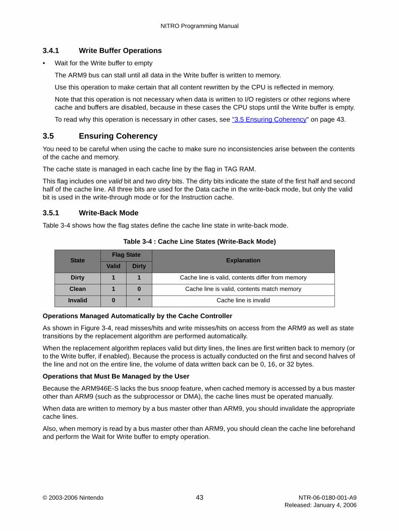
NITRO Programming Manual
3.4.1 Write Buffer Operations• Wait for the Write buffer to empty
The ARM9 bus can stall until all data in the Write buffer is written to memory.
Use this operation to make certain that all content rewritten by the CPU is reflected in memory.
Note that this operation is not necessary when data is written to I/O registers or other regions where cache and buffers are disabled, because in these cases the CPU stops until the Write buffer is empty.
To read why this operation is necessary in other cases, see "3.5 Ensuring Coherency" on page 43.
3.5 Ensuring CoherencyYou need to be careful when using the cache to make sure no inconsistencies arise between the contents of the cache and memory.
The cache state is managed in each cache line by the flag in TAG RAM.
This flag includes one valid bit and two dirty bits. The dirty bits indicate the state of the first half and second half of the cache line. All three bits are used for the Data cache in the write-back mode, but only the valid bit is used in the write-through mode or for the Instruction cache.
3.5.1 Write-Back ModeTable 3-4 shows how the flag states define the cache line state in write-back mode.
Table 3-4 : Cache Line States (Write-Back Mode)
Operations Managed Automatically by the Cache Controller
As shown in Figure 3-4, read misses/hits and write misses/hits on access from the ARM9 as well as state transitions by the replacement algorithm are performed automatically.
When the replacement algorithm replaces valid but dirty lines, the lines are first written back to memory (or to the Write buffer, if enabled). Because the process is actually conducted on the first and second halves of the line and not on the entire line, the volume of data written back can be 0, 16, or 32 bytes.
Operations that Must Be Managed by the User
Because the ARM946E-S lacks the bus snoop feature, when cached memory is accessed by a bus master other than ARM9 (such as the subprocessor or DMA), the cache lines must be operated manually.
When data are written to memory by a bus master other than ARM9, you should invalidate the appropriate cache lines.
Also, when memory is read by a bus master other than ARM9, you should clean the cache line beforehand and perform the Wait for Write buffer to empty operation.
StateFlag State
ExplanationValid Dirty
Dirty 1 1 Cache line is valid, contents differ from memory
Clean 1 0 Cache line is valid, contents match memory
Invalid 0 * Cache line is invalid
© 2003-2006 Nintendo 43 NTR-06-0180-001-A9Released: January 4, 2006

NITRO Programming Manual
Figure 3-4 : Cache line state transitions (write-back mode)
Example
• If the program in main memory is overwritten by an overlay, etc.
Invalidate the Instruction cache in the appropriate region.
3.5.2 Write-Through ModeTable 3-5 shows how the flag states define the cache line state in write-through mode.
Table 3-5 : Cache Line States (Write-Through Mode)
Operations Managed Automatically by the Cache Controller
As shown in Figure 3-5, read misses/hits and write misses/hits for access from the ARM9 as well as state transitions by the replacement algorithm are performed automatically.
Operations that Must Be Managed by the User
Because the ARM946E-S lacks the bus snoop feature, when cached memory is accessed by a bus master other than ARM9 (such as the subprocessor, DMA, etc.), the cache lines must be operated manually.
When data are written to memory by a bus master other than ARM9, you should invalidate the appropriate cache lines.
Also, when memory is read by a bus master other than ARM9, perform the Wait for Write buffer to empty operation.
StateFlag State
ExplanationValid Dirty
Clean 1 * Cache line is valid, contents match memory
Invalid 0 * Cache line is invalid
- Clean & Invalidate
- Invalidate
Line Fetch due to Read Miss
Write Miss
Write Hit
Dirty
CleanInvalid
- Write Hit
- Read Hit
- Clean & Invalidate - Invalidate
- Write-back using another Bus Master
- Clean
- Replace using the Replacement Algorithm
- Read Hit
- Replace using the Replacement Algorithm- Clean
NTR-06-0180-001-A9 44 © 2003-2006 NintendoReleased: January 4, 2006

NITRO Programming Manual
Figure 3-5 : Cache line state transitions (write-through mode)
Example
• If the program in main memory is overwritten by an overlay, etc.
Invalidate the Instruction cache in the appropriate region.
- Invalidate
- Line Fetch due to Read Miss
- Write Miss- Write Hit- Replace Using the Replacement Algorithm
- Read Hit
CleanInvalid
© 2003-2006 Nintendo 45 NTR-06-0180-001-A9Released: January 4, 2006

NITRO Programming Manual
NTR-06-0180-001-A9 46 © 2003-2006 NintendoReleased: January 4, 2006
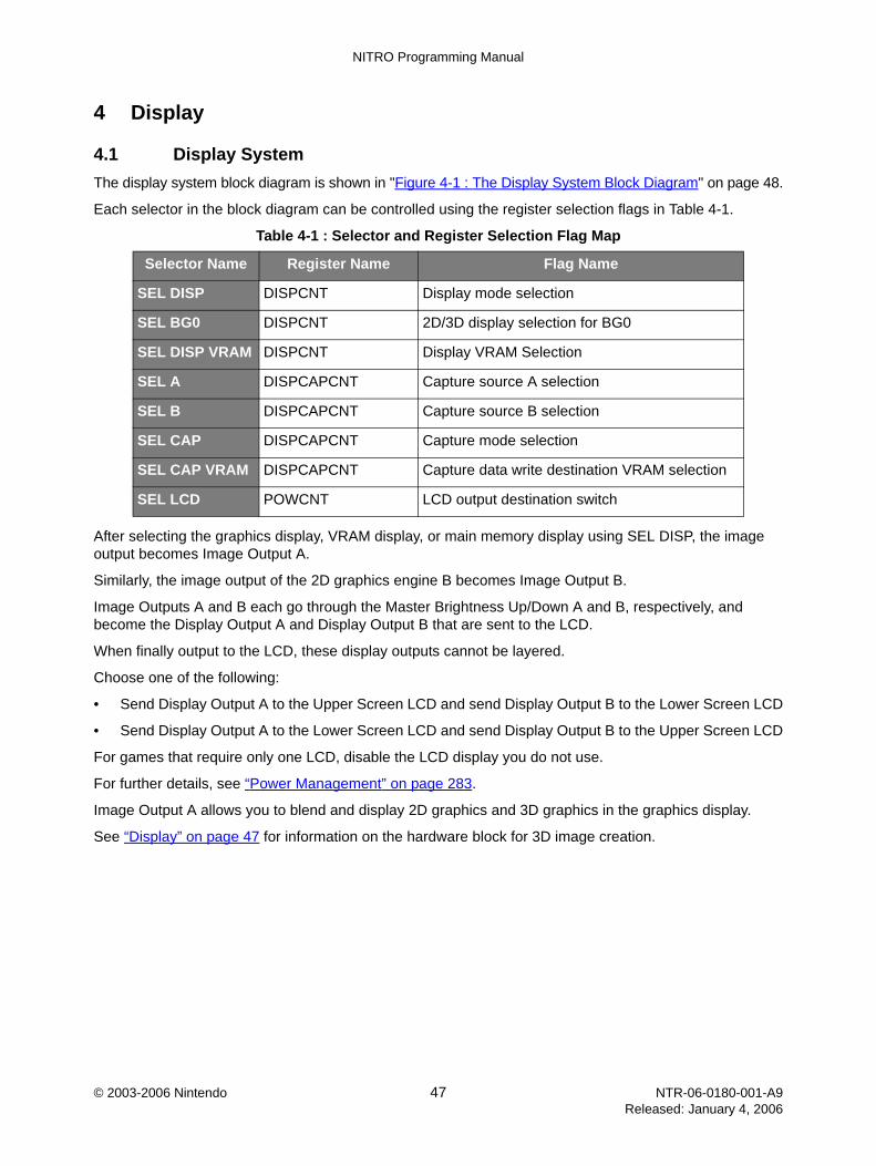
NITRO Programming Manual
4 Display
4.1 Display SystemThe display system block diagram is shown in "Figure 4-1 : The Display System Block Diagram" on page 48.
Each selector in the block diagram can be controlled using the register selection flags in Table 4-1.
Table 4-1 : Selector and Register Selection Flag Map
After selecting the graphics display, VRAM display, or main memory display using SEL DISP, the image output becomes Image Output A.
Similarly, the image output of the 2D graphics engine B becomes Image Output B.
Image Outputs A and B each go through the Master Brightness Up/Down A and B, respectively, and become the Display Output A and Display Output B that are sent to the LCD.
When finally output to the LCD, these display outputs cannot be layered.
Choose one of the following:
• Send Display Output A to the Upper Screen LCD and send Display Output B to the Lower Screen LCD
• Send Display Output A to the Lower Screen LCD and send Display Output B to the Upper Screen LCD
For games that require only one LCD, disable the LCD display you do not use.
For further details, see “Power Management” on page 283.
Image Output A allows you to blend and display 2D graphics and 3D graphics in the graphics display.
See “Display” on page 47 for information on the hardware block for 3D image creation.
Selector Name Register Name Flag Name
SEL DISP DISPCNT Display mode selection
SEL BG0 DISPCNT 2D/3D display selection for BG0
SEL DISP VRAM DISPCNT Display VRAM Selection
SEL A DISPCAPCNT Capture source A selection
SEL B DISPCAPCNT Capture source B selection
SEL CAP DISPCAPCNT Capture mode selection
SEL CAP VRAM DISPCAPCNT Capture data write destination VRAM selection
SEL LCD POWCNT LCD output destination switch
© 2003-2006 Nintendo 47 NTR-06-0180-001-A9Released: January 4, 2006
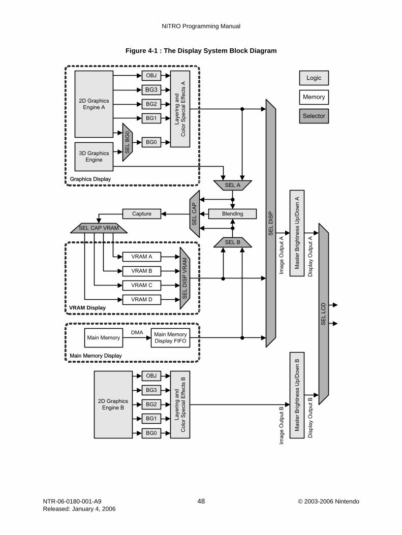
NITRO Programming Manual
Figure 4-1 : The Display System Block Diagram
VRAM A
VRAM B
VRAM C
VRAM D SEL
DIS
P VR
AM
Main Memory Display FIFO
SEL
DIS
PCapture
Main Memory Display
Mas
ter B
right
ness
Up/
Dow
n A
SEL
BG0
3D Graphics Engine
2D Graphics Engine A
BG0
OBJ
BG3
BG2
BG1
Laye
ring
and
Col
or S
peci
al E
ffect
s A
Main MemoryDMA
SEL A
SEL B
VRAM Display
Graphics Display
SEL
CAP
Blending
2D Graphics Engine B
BG0
OBJ
BG3
BG2
BG1 Laye
ring
and
Col
or S
peci
al E
ffect
s B
SEL CAP VRAM
Mas
ter B
right
ness
Up/
Dow
n B
SEL
LCD
Logic
Memory
Selector
Imag
e O
utpu
t A
Dis
play
Out
put A
Imag
e O
utpu
t B
Dis
play
Out
put B
NTR-06-0180-001-A9 48 © 2003-2006 NintendoReleased: January 4, 2006

NITRO Programming Manual
4.2 LCDThe specifications for the two LCD controllers included on the DS are shown below.
Both LCDs have the same specifications but the directions differ, so the order of RGB pixel arrays differs.
4.2.1 LCD Controller SpecificationsThe LCD clock specifications of the LCD controller are shown in Table 4-2, the LCD scan timing is shown in Figure 4-2, and the specifications for the LCD scan timing are shown in "Table 4-3 : LCD Scan Timing Specifications" on page 50.
Table 4-2 : LCD Clock Specifications
Figure 4-2 : LCD Scan Timing
LCD Clock Frequency (time)
Image Processing Clock 33.513982 Mhz (29.838293 ns)
Dot Clock 5.585664 Mhz (179.029757 ns) (see note)
Note: The Dot Clock is 1/6 of the Image Processing Clock.
Display Screen
V-Blank
H-Blank
256 dots
355 dots
192
lines
263
lines
99 dots
71 li
nes
© 2003-2006 Nintendo 49 NTR-06-0180-001-A9Released: January 4, 2006

NITRO Programming Manual
Table 4-3 : LCD Scan Timing Specifications
The V-Blank cycle for the 3D rendering engine consists of the 23 lines 191–213. For details, see “Rendering Engine” on page 224.
Item Spec Period Reference: AGB Value
Display Screen Size
Horizontal Dot Count 256 dots 45.8316 μs 240 dots (57.221 μs)
Vertical Line Count 192 lines 12.2027 ms 160 lines (11.749 ms)
Total Dot Count
Horizontal Dot Count 355 dots 63.5556 μs 308 dots (73.433 μs)
Vertical Line Count 263 lines 16.7151 ms 228 lines (16.743 ms)
BlankingH-Blank Dot Count 99 dots 17.7239 μs 68 dots (16.212 μs)
V-Blank Line Count 71 lines 4.5124 ms 68 lines (4.994 ms)
Scan CycleH-Cycle 15.7343 KHz 63.5556 μs 13.618 KHz (73.443 μs)
V-Cycle 59.8261 Hz 16.7151 ms 59.727 Hz (16.743 ms)
NTR-06-0180-001-A9 50 © 2003-2006 NintendoReleased: January 4, 2006
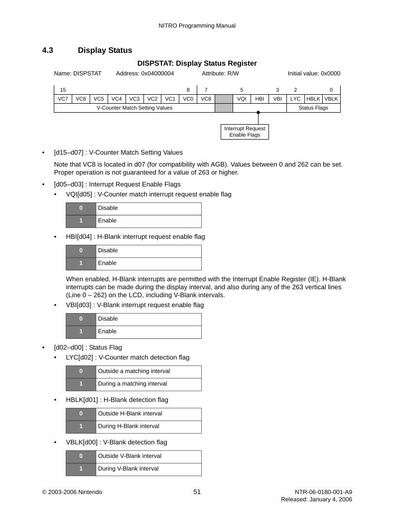
NITRO Programming Manual
4.3 Display StatusDISPSTAT: Display Status Register
Name: DISPSTAT Address: 0x04000004 Attribute: R/W Initial value: 0x0000
• [d15–d07] : V-Counter Match Setting Values
Note that VC8 is located in d07 (for compatibility with AGB). Values between 0 and 262 can be set. Proper operation is not guaranteed for a value of 263 or higher.
• [d05–d03] : Interrupt Request Enable Flags• VQI[d05] : V-Counter match interrupt request enable flag
• HBI[d04] : H-Blank interrupt request enable flag
When enabled, H-Blank interrupts are permitted with the Interrupt Enable Register (IE). H-Blank interrupts can be made during the display interval, and also during any of the 263 vertical lines (Line 0 – 262) on the LCD, including V-Blank intervals.
• VBI[d03] : V-Blank interrupt request enable flag
• [d02–d00] : Status Flag• LYC[d02] : V-Counter match detection flag
• HBLK[d01] : H-Blank detection flag
• VBLK[d00] : V-Blank detection flag
0 Disable
1 Enable
0 Disable
1 Enable
0 Disable
1 Enable
0 Outside a matching interval
1 During a matching interval
0 Outside H-Blank interval
1 During H-Blank interval
0 Outside V-Blank interval
1 During V-Blank interval
VC7 VC6 VC5 VC4 VC3 VC2 VC1 VC0 VC8 VQI HBI VBI LYC HBLK VBLK
V-Counter Match Setting Values Status Flags
15 8 7 5 3 2 0
Interrupt Request Enable Flags
© 2003-2006 Nintendo 51 NTR-06-0180-001-A9Released: January 4, 2006

NITRO Programming Manual
Note: V-Blank detection flag becomes 1 at the moment it reaches Line 192, and becomes 0 when it reaches Line 262. This is because the OBJ rendering circuitry accesses OBJ-VRAM and OAM starting at Line 262, which is one line before the actual display. In addition, the timing that ends access to OBJ-VRAM and OAM depends on whether the OBJ process is performed during H-Blank. On the other hand, BG-VRAM, BG Palette RAM, and OBJ Palette RAM begin access at Line 0, and end at Line 191. This is summarized in Table 4-4 below.
Table 4-4 : Period when Graphics Engines Access MemoryMemory Accessed by Graphics Engines V-Counter Value
Access period when OBJ render-ing circuitry accesses OBJ-VRAM and OAM
Perform OBJ process during H-Blank 0-191, 262Does not perform OBJ process during H-Blank 0-190, 262
Access period when rendering circuitry accesses BG-VRAM, BG Palette RAM, and OBJ Palette RAM 0-191
(Reference) Period when the V-Blank deflection flag becomes 1 192-261
NTR-06-0180-001-A9 52 © 2003-2006 NintendoReleased: January 4, 2006

NITRO Programming Manual
VCOUNT: V-Counter RegisterName: VCOUNT Address: 0x04000006 Attribute: R/W Initial value: 0x0000
• [d08–d00] : V-Counter Values
Unlike the bit arrangement of the V-Counter Match Setting Values in the DISPSTAT register, these bits are in a normal arrangement.
1. When reading values
Can read which of the LCD's total 263 lines is currently displayed. The readout value is between 0 and 262.
If the readout value is between 0 and 191, images are being drawn. If the value is between 192 and 262, it is a V-Blank period.
To learn about the LCD's display timing, see “LCD” on page 49.
2. When writing values
Written values are reflected when the hardware's V-Counter is updated.
By using this register, you can synchronize all NITRO V cycles by adjusting the V-count value when communicating among multiple DS devices.
Confirm that the current value of the V-Counter is between 202 and 212, and write values only between 202 and 212. Proper operation of the 3D engine is not guaranteed when writing values outside this range.
Note: When there is a conflict between the access to the display circuit VRAM and the access to VRAM from the CPU, the display circuit VRAM takes precedence.
Because the dot clock of the LCD controller is 1/6 of a cycle of the image processing clock and the system clock, the timing for the LCD controller to access the VRAM is once every six cycles.
With this timing, when simultaneously accessing from the CPU, the CPU access must wait for one cycle.
V8 V7 V6 V5 V4 V3 V2 V1 V0
V-Counter Values
15 8 7 0
© 2003-2006 Nintendo 53 NTR-06-0180-001-A9Released: January 4, 2006
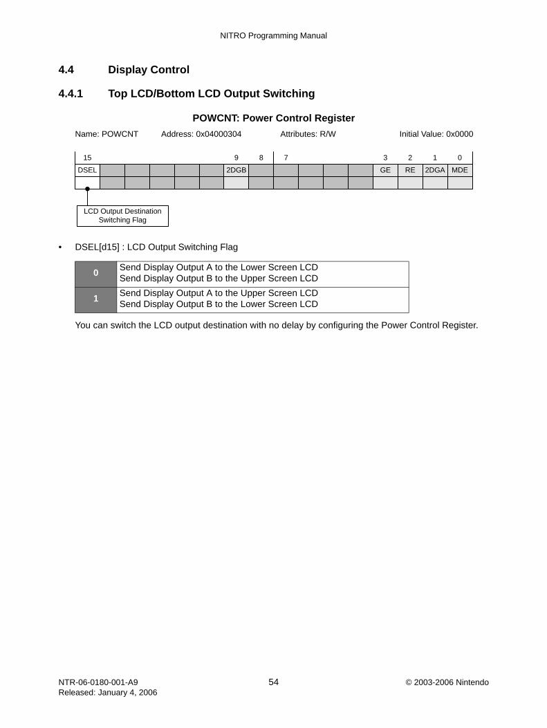
NITRO Programming Manual
4.4 Display Control
4.4.1 Top LCD/Bottom LCD Output Switching
POWCNT: Power Control RegisterName: POWCNT Address: 0x04000304 Attributes: R/W Initial Value: 0x0000
• DSEL[d15] : LCD Output Switching Flag
You can switch the LCD output destination with no delay by configuring the Power Control Register.
0 Send Display Output A to the Lower Screen LCDSend Display Output B to the Upper Screen LCD
1 Send Display Output A to the Upper Screen LCDSend Display Output B to the Lower Screen LCD
DSEL 2DGB GE RE 2DGA MDE
15 8 7 13 2 0
LCD Output Destination Switching Flag
9
NTR-06-0180-001-A9 54 © 2003-2006 NintendoReleased: January 4, 2006
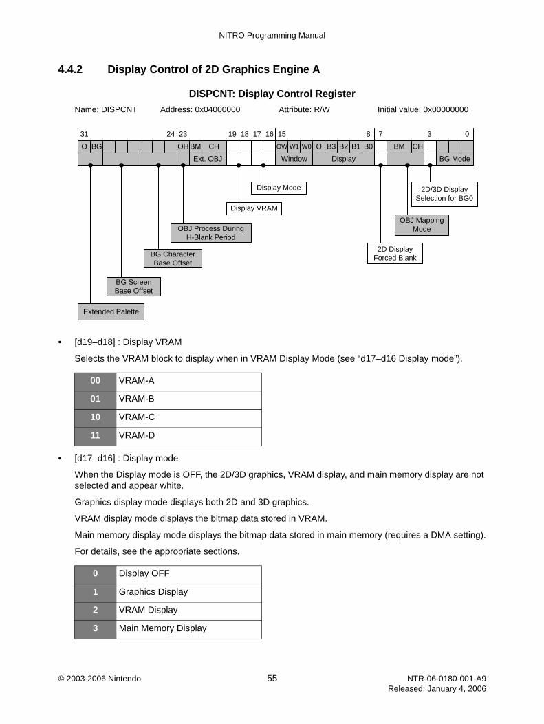
NITRO Programming Manual
4.4.2 Display Control of 2D Graphics Engine A
DISPCNT: Display Control RegisterName: DISPCNT Address: 0x04000000 Attribute: R/W Initial value: 0x00000000
• [d19–d18] : Display VRAM
Selects the VRAM block to display when in VRAM Display Mode (see “d17–d16 Display mode”).
• [d17–d16] : Display mode
When the Display mode is OFF, the 2D/3D graphics, VRAM display, and main memory display are not selected and appear white.
Graphics display mode displays both 2D and 3D graphics.
VRAM display mode displays the bitmap data stored in VRAM.
Main memory display mode displays the bitmap data stored in main memory (requires a DMA setting).
For details, see the appropriate sections.
00 VRAM-A
01 VRAM-B
10 VRAM-C
11 VRAM-D
0 Display OFF
1 Graphics Display
2 VRAM Display
3 Main Memory Display
O BG OH BM CH OW W1 W0 O B3 B2 B1 B0 BM CH
Ext. OBJ Window Display BG Mode
31 24 23 16 15 8 7 0
Extended Palette
BG Screen Base Offset
BG Character Base Offset
OBJ Process During H-Blank Period
Display VRAM
Display Mode
2D Display Forced Blank
OBJ Mapping Mode
2D/3D Display Selection for BG0
171819 3
© 2003-2006 Nintendo 55 NTR-06-0180-001-A9Released: January 4, 2006
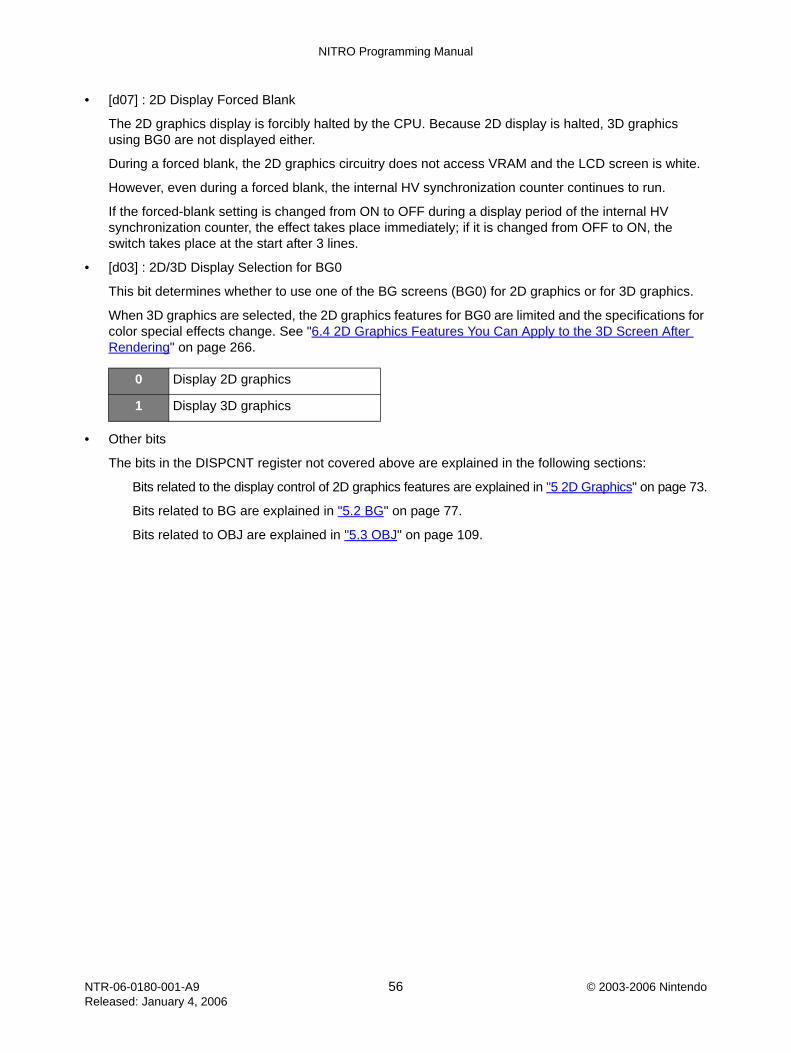
NITRO Programming Manual
• [d07] : 2D Display Forced Blank
The 2D graphics display is forcibly halted by the CPU. Because 2D display is halted, 3D graphics using BG0 are not displayed either.
During a forced blank, the 2D graphics circuitry does not access VRAM and the LCD screen is white.
However, even during a forced blank, the internal HV synchronization counter continues to run.
If the forced-blank setting is changed from ON to OFF during a display period of the internal HV synchronization counter, the effect takes place immediately; if it is changed from OFF to ON, the switch takes place at the start after 3 lines.
• [d03] : 2D/3D Display Selection for BG0
This bit determines whether to use one of the BG screens (BG0) for 2D graphics or for 3D graphics.
When 3D graphics are selected, the 2D graphics features for BG0 are limited and the specifications for color special effects change. See "6.4 2D Graphics Features You Can Apply to the 3D Screen After Rendering" on page 266.
• Other bits
The bits in the DISPCNT register not covered above are explained in the following sections:
Bits related to the display control of 2D graphics features are explained in "5 2D Graphics" on page 73.
Bits related to BG are explained in "5.2 BG" on page 77.
Bits related to OBJ are explained in "5.3 OBJ" on page 109.
0 Display 2D graphics
1 Display 3D graphics
NTR-06-0180-001-A9 56 © 2003-2006 NintendoReleased: January 4, 2006
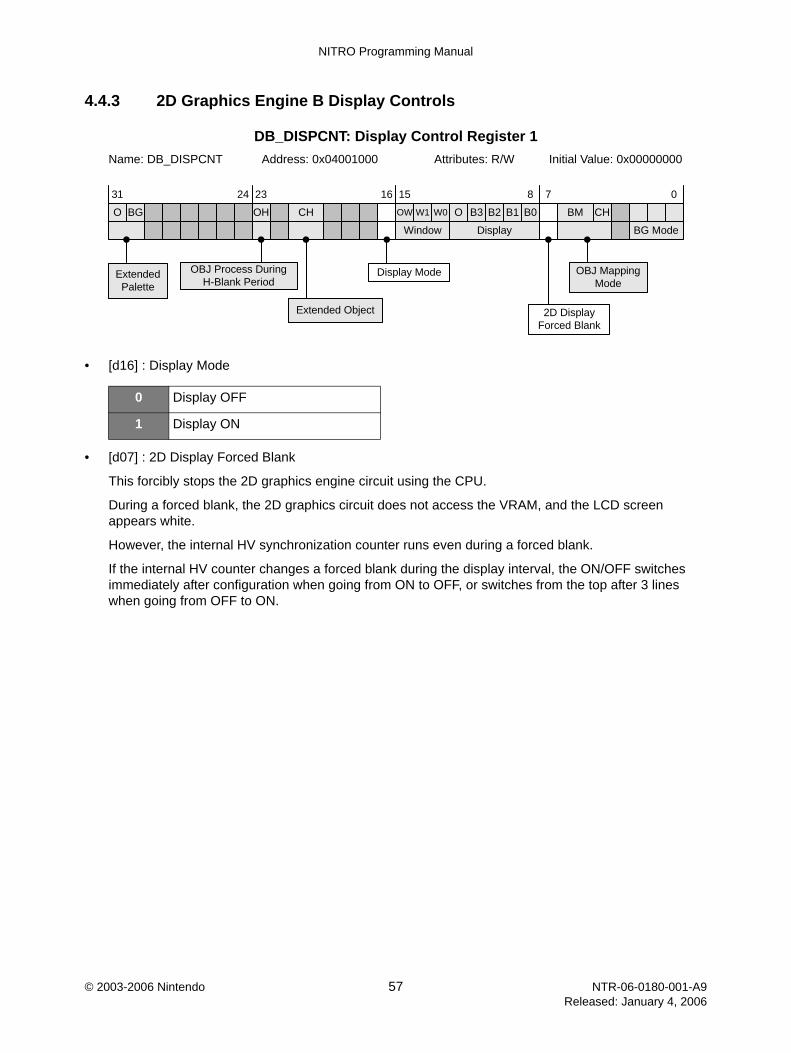
NITRO Programming Manual
4.4.3 2D Graphics Engine B Display Controls
DB_DISPCNT: Display Control Register 1Name: DB_DISPCNT Address: 0x04001000 Attributes: R/W Initial Value: 0x00000000
• [d16] : Display Mode
• [d07] : 2D Display Forced Blank
This forcibly stops the 2D graphics engine circuit using the CPU.
During a forced blank, the 2D graphics circuit does not access the VRAM, and the LCD screen appears white.
However, the internal HV synchronization counter runs even during a forced blank.
If the internal HV counter changes a forced blank during the display interval, the ON/OFF switches immediately after configuration when going from ON to OFF, or switches from the top after 3 lines when going from OFF to ON.
0 Display OFF
1 Display ON
O BG OH CH OW W1 W0 O B3 B2 B1 B0 BM CH
Window Display BG Mode
31 24 23 16 15 8 7 0
Extended Palette
OBJ Process During H-Blank Period
2D Display Forced Blank
OBJ Mapping Mode
Extended Object
Display Mode
© 2003-2006 Nintendo 57 NTR-06-0180-001-A9Released: January 4, 2006

NITRO Programming Manual
4.4.4 Display ModesAs indicated in Table 4-5, on the Display Output A side (the 2D Graphics Engine A), there are modes that display the bitmap data in the VRAM and main memory in addition to the mode that displays the images generated by the graphics circuit.
Table 4-5 : An Overview of the Display Modes (2D Graphics Engine A)
As indicated in Table 4-6, on the Display Output B side (the 2D graphics engine B), the only mode selection is graphics display ON or OFF.
Table 4-6 : An Overview of the Display Modes (2D Graphics Engine B)
"Figure 4-3 : Display Mode Selection (Display Output A Side Only)" on page 59 is a simplified version of the display mode for Display Output A in "Figure 4-1 : The Display System Block Diagram" on page 48.
Display Mode Number Display Mode Display
SizeFrame Rate
Features
3D Display
Character BG Display
Bitmap BG Display
OBJ Display
0 Display OFF - - - - - -
1 Graphics Display 256x192 60 fps X X X X
2 VRAM Display 256x192 60 fps X
3 Main Memory Display 256x192 60 fps X
Display Mode Number Display Mode Display
SizeFrame Rate
Feature
Character BG Display
Bitmap BG Display
OBJDisplay
0 Display OFF - - - - -
1 Graphics Display 256x192 60 fps X X X
NTR-06-0180-001-A9 58 © 2003-2006 NintendoReleased: January 4, 2006

NITRO Programming Manual
Figure 4-3 : Display Mode Selection (Display Output A Side Only)
SE
L D
ISP
Main Memory DisplayM
aste
r Brig
htne
ss U
p / D
own
Logic
Memory
Output
3D GraphicsEngine
2D GraphicsEngine A
VRAM Display
Graphics Display
DISPCNT RegisterDisplay Mode Selection
VRAM
Main Memory
Selector
© 2003-2006 Nintendo 59 NTR-06-0180-001-A9Released: January 4, 2006

NITRO Programming Manual
4.4.4.1 Graphics Display ModeThis mode displays images generated with the 2D and 3D graphics features.
See "Figure 4-1 : The Display System Block Diagram" on page 48 for information about the entire display system.
To read about the various graphic features, see "5 2D Graphics" on page 73 and "6 3D Graphics" on page 153.
• Graphics display mode – Example 1
The example in Figure 4-4 shows how the results of 3D rendering are layered with the 2D screen and displayed.
Although 3D display is handled as the BG0 screen, the 2D graphics features of BG0 are limited and the color special effect specifications have changed. See "6.4 2D Graphics Features You Can Apply to the 3D Screen After Rendering" on page 266.
Figure 4-4 : Display Mode Selection (Display Output A Side Only)
SEL
DIS
P
Main Memory Display
Mas
ter B
right
ness
Up/
Dow
n
Logic
Memory
Output
SE
L BG
0
3D Screen
2D Screen(BG + OBJ)
BG0
OBJ
BG3
BG2
BG1
Laye
ring
and
Col
or S
peci
alE
ffect
s
VRAM Display
Graphics Display
DISPCNT Register2D/3D DisplaySelection for BG0
DISPCNT RegisterDisplay Mode Selection
Capture
Selector
NTR-06-0180-001-A9 60 © 2003-2006 NintendoReleased: January 4, 2006

NITRO Programming Manual
• Graphics display mode – Example 2
In the example shown in "Figure 4-5 : An Example of Displaying the Bitmap OBJ Results of 3D Rendering" on page 62, the results of 3D rendering are pasted in a Bitmap OBJ and displayed.
The rendering engine's clear alpha value is set to 0 and the 3D rendering result is captured. Then, in the next frame, the VRAM is assigned to a bitmap OBJ according to the value of the RAM Bank Control register. This enables the 3D rendering result to be displayed as an OBJ.
At this moment in the sequence, alpha value segments that remain 0 in the 3D alpha-blending process are transparent. (See the "6.3.7 Alpha-Blending" on page 256 for the capture feature and the rendering engine.)
In this example, double buffering occurs by alternately assigning VRAM-A and VRAM-B to LCDC and OBJ-VRAM.
© 2003-2006 Nintendo 61 NTR-06-0180-001-A9Released: January 4, 2006
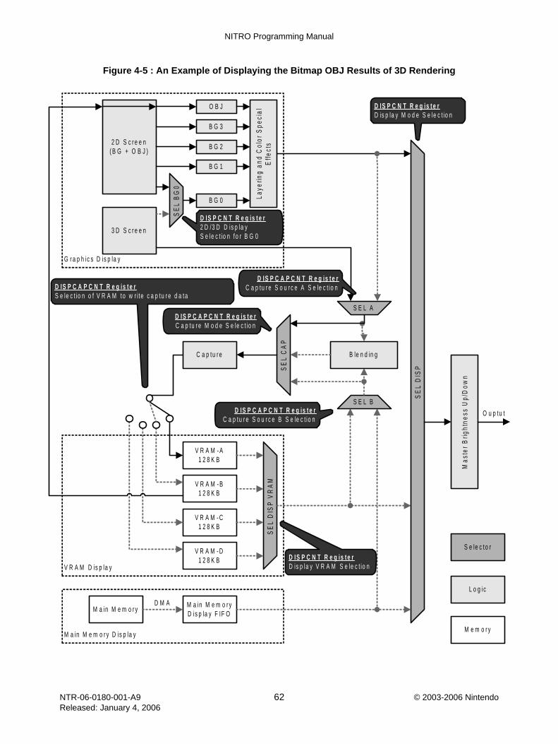
NITRO Programming Manual
Figure 4-5 : An Example of Displaying the Bitmap OBJ Results of 3D Rendering
V R A M - A1 2 8 K B
V R A M - B1 2 8 K B
V R A M - C1 2 8 K B
V R A M - D1 2 8 K B
SEL
DIS
P V
RA
M
M a in M e m o r yD is p la y F IF O
SEL
DIS
P
C a p tu r e
M a in M e m o r y D is p la y
Mas
ter B
right
ness
Up/
Dow
n
L o g ic
M e m o r y
O u p tu t
SEL
BG
0
3 D S c r e e n
2 D S c r e e n( B G + O B J )
B G 0
O B J
B G 3
B G 2
B G 1
Laye
ring
and
Col
or S
peci
alEf
fect
s
M a in M e m o r yD M A
S E L A
S E L B
V R A M D is p la y
G r a p h ic s D is p la y
D IS P C N T R e g is t e r2 D /3 D D is p la yS e le c t io n fo r B G 0
D IS P C A P C N T R e g is t e rS e le c t io n o f V R A M to w r i te c a p tu r e d a ta
D IS P C N T R e g is t e rD is p la y V R A M S e le c t io n
D IS P C A P C N T R e g is t e rC a p tu r e S o u r c e A S e le c t io n
D IS P C N T R e g is t e rD is p la y M o d e S e le c t io n
SE
L C
AP
B le n d in g
D IS P C A P C N T R e g is t e rC a p tu r e M o d e S e le c t io n
D IS P C A P C N T R e g is t e rC a p tu r e S o u r c e B S e le c t io n
S e le c to r
NTR-06-0180-001-A9 62 © 2003-2006 NintendoReleased: January 4, 2006

NITRO Programming Manual
4.4.4.2 VRAM Display ModeWhen the DISPCNT register is set for VRAM display mode, one frame’s worth of bitmap data stored in a VRAM block is shown from the start of the next display. The DISPCNT register can specify which VRAM block to use.
VRAM is displayed using a different system than the 2D circuitry and the 3D circuitry, so when the mode is set to VRAM display mode, images can be created by the graphics circuitry and captured to VRAM at the same time that images are being displayed. (See "Figure 4-1 : The Display System Block Diagram" on page 48).
You can specify the same VRAM block for display and for capturing images.
For details about capturing images, see "4.5 Display Capture" on page 67.
The pixel data format for VRAM display mode is shown below.
VRAM Display Mode Data Format
Figure 4-6 shows the VRAM address map of the LCD pixels.
Figure 4-6 : The VRAM Address Map of the LCD Pixels
• VRAM display mode - Example
In "Figure 4-7 : An Example of the Motion Blur Effect that Uses the Display Capture" on page 64, the image created by the graphic circuitry is put into VRAM using the capture feature, and then the image is displayed with the mode set to VRAM Display. When the image is captured, a motion blur effect is achieved by blending with the display-use VRAM.
BLUE GREEN RED
Pixel Color Data
15 14 10 9 8 7 5 4 0
Dot 0 1 2 3 253 254 255
Line 0 0h 2h 4h 6h 1FAh 1FCh 1FEh
1 200h 202h 204h 206h 3FAh 3FCh 3FEh
2 400h 402h 5FCh 5FEh
3 600h 602h 7FCh 7FEh
4 800h 9FEh
187 17600h 177FEh
188 17800h 17802h 179FCh 179FEh
189 17A00h 17A02h 17BFCh 17BFEh
190 17C00h 17C02h 17C04h 17C06h 17DFAh 17DFCh 17DFEh
191 17E00h 17E02h 17E04h 17E06h 17FFAh 17FFCh 17FFEh
© 2003-2006 Nintendo 63 NTR-06-0180-001-A9Released: January 4, 2006
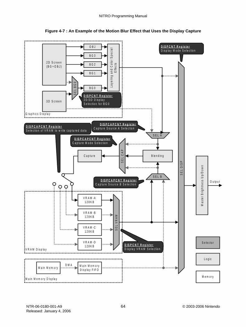
NITRO Programming Manual
Figure 4-7 : An Example of the Motion Blur Effect that Uses the Display Capture
V R A M - A1 2 8 K B
V R A M - B1 2 8 K B
V R A M - C1 2 8 K B
V R A M - D1 2 8 K B
SEL
VR
AM
M a in M e m o r yD is p la y F IF O
SEL
DIS
P
C a p tu r e
M a in M e m o r y D is p la y
Mas
ter B
right
ness
Up/
Dow
n
L o g ic
M e m o r y
O u tp u t
SEL
BG
0
3 D S c r e e n
2 D S c r e e n( B G + O B J )
B G 0
O B J
B G 3
B G 2
B G 1
Laye
ring
and
Col
or S
peci
alEf
fect
s
M a in M e m o r yD M A
S E L A
S E L B
V R A M D is p la y
G r a p h ic s D is p la y
D IS P C N T R e g is t e r2 D /3 D D is p la yS e le c t io n fo r B G 0
D IS P C A P C N T R e g is t e rS e le c t io n o f V R A M to w r i t e c a p tu r e d d a ta
D IS P C N T R e g is t e rD is p la y V R A M S e le c t io n
D IS P C A P C N T R e g is t e rC a p tu r e S o u r c e A S e le c t io n
D IS P C N T R e g is t e rD is p la y M o d e S e le c t io n
SE
L C
AP
B le n d in g
D IS P C A P C N T R e g is t e rC a p tu r e M o d e S e le c t io n
D IS P C A P C N T R e g is t e rC a p tu r e S o u r c e B S e le c t io n
S e le c to r
NTR-06-0180-001-A9 64 © 2003-2006 NintendoReleased: January 4, 2006

NITRO Programming Manual
4.4.4.3 Main Memory Display ModeThis mode enables the display of bitmap data held in main memory. When the DISPCNT register is set to main memory display mode, the data held in the main memory display FIFO is transferred to the LCD module at the beginning of the next display. A data request is sent to DMA for every data transfer.
There is a four-layer FIFO between the main memory display FIFO register and the LCD module, and the LCD module takes four words at a time. For this reason, you should write four layers of data at a time to the main memory display FIFO register.
To be more specific, after setting the DMA transfer bit width to 32 bits and the word count to 4, set the DMA startup mode to main memory display mode. For this mode, be sure to set the DMA source address to the main memory region.
Table 4-7 shows the DMA configuration when using the main memory display mode.
Table 4-7 : DMA Configuration when Using the Main Memory Display Mode
For details about the DMA configuration, see "7 DMA" on page 271.
Data from main memory is displayed using a system other than the 2D and 3D circuitry, so when the mode is set to main memory display, images can be created by the graphics circuitry and captured to VRAM at the same time that images are being displayed. (See "Figure 4-1 : The Display System Block Diagram" on page 48.)
Main Memory Display FIFO RegisterName: DISP_MMEM_FIFO Address: 0x04000068 Attribute: R/W Initial value: 0x00000000
"Figure 4-8 : The LCD Pixel EVEN/ODD Map of the Main Memory Display FIFO Register" on page 66 shows the LCD pixel EVEN/ODD map of the main memory display FIFO register.
Setting Value
Source Address Main memory
Transfer Bit Width 32 bits
Word Count 4
BLUE GREEN RED BLUE GREEN RED
ODD EVEN
31 30 26 25 24 23 21 20 16 15 14 10 9 8 7 5 4 0
© 2003-2006 Nintendo 65 NTR-06-0180-001-A9Released: January 4, 2006

NITRO Programming Manual
Figure 4-8 : The LCD Pixel EVEN/ODD Map of the Main Memory Display FIFO Register
Dot 0 1 2 3 253 254 255
Line 0 EVEN ODD EVEN ODD ODD EVEN ODD
1 EVEN ODD EVEN ODD ODD EVEN ODD
2 EVEN ODD EVEN ODD
3 EVEN ODD EVEN ODD
4 EVEN ODD
187 EVEN ODD
188 EVEN ODD EVEN ODD
189 EVEN ODD EVEN ODD
190 EVEN ODD EVEN ODD ODD EVEN ODD
191 EVEN ODD EVEN ODD ODD EVEN ODD
NTR-06-0180-001-A9 66 © 2003-2006 NintendoReleased: January 4, 2006
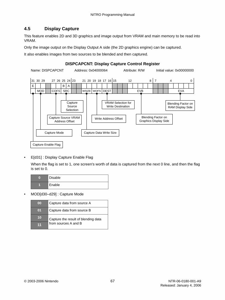
NITRO Programming Manual
4.5 Display CaptureThis feature enables 2D and 3D graphics and image output from VRAM and main memory to be read into VRAM.
Only the image output on the Display Output A side (the 2D graphics engine) can be captured.
It also enables images from two sources to be blended and then captured.
DISPCAPCNT: Display Capture Control RegisterName: DISPCAPCNT Address: 0x04000064 Attribute: R/W Initial value: 0x00000000
• E[d31] : Display Capture Enable Flag
When the flag is set to 1, one screen's worth of data is captured from the next 0 line, and then the flag is set to 0.
• MOD[d30–d29] : Capture Mode
0 Disable
1 Enable
00 Capture data from source A
01 Capture data from source B
10 Capture the result of blending data from sources A and B11
E B A
MOD WSIZE WOFS DEST EVB EVA
31 24 23 16 15 8 7 0
Capture Enable Flag
Capture Mode
Capture Source VRAM Address Offset
Capture Data Write Size
VRAM Selection for Write Destination
Blending Factor on Graphics Display Side
Blending Factor on RAM Display Side
COFS SRC
Write Address Offset
412171819202125262730 29
Capture Source
Selection
© 2003-2006 Nintendo 67 NTR-06-0180-001-A9Released: January 4, 2006

NITRO Programming Manual
• COFS[d27–d26] : Read Address Offset for Capture Data Source VRAM
Invalid in VRAM display mode.
If the offset exceeds 0x20000 during reading, the reading continues after wrapping to address 0x00000.
• SRC[d25–d24] : Capture Data Source Selection
B
A
• WSIZE[d21–d20] : Capture Size
Specifies the size when writing the capture data. With RAM captures, 1 line is always read as a 256-dot image, so you cannot blend and then capture (see Capture mode above) when the setting is 128x128 dots.
• WOFS[d19–d18] : Address Offset for Capture Data Write
This can specify the offset value for the address where data is written in the specified VRAM. If the offset exceeds 0x20000 during writing, the writing continues after wrapping to address 0x00000.
00 0x00000
01 0x08000
10 0x10000
11 0x18000
0 VRAM
1 Main Memory
0 Graphics display screen (after 3D/2D blending)
1 3D screen
00 128x128 dots (0x08000 bytes)
01 256x64 dots (0x08000 bytes)
10 256x128 dots (0x10000 bytes)
11 256x192 dots (0x18000 bytes)
00 0x00000
01 0x08000
10 0x10000
11 0x18000
NTR-06-0180-001-A9 68 © 2003-2006 NintendoReleased: January 4, 2006

NITRO Programming Manual
• DEST[d17–d16] : Capture Data Write Destination VRAM Selection
The write destination VRAM must be allocated to the LCDC.
• EVB[d12–d08], EVA[d04–d00] : Blending Factors
Sets the blending factors for capture sources A and B. See below for the calculation method.
In VRAM display mode, you can set the same VRAM block for display VRAM and for writing the captured image data.
Capture Data Format
Although 3D graphics are output in R:G:B=6:6:6 color, because capture occurs in R:G:B=5:5:5 color (employing the upper 5 bits), the image gradient becomes a little coarse.
Figure 4-9 shows the LCD pixel map of the captured data when the capture size is 256 x 192 dots.
Figure 4-9 : The LCD Pixel Map of the Capture Data (When the Capture Size is 256 x 192 Dots)
00 VRAM-A
01 VRAM-B
10 VRAM-C
11 VRAM-D
A BLUE GREEN RED
α Pixel Color Data
15 14 10 9 8 7 5 4 0
Dot 0 1 2 3 253 254 255
Line 0 0h 2h 4h 6h 1FAh 1FCh 1FEh
1 200h 202h 204h 206h 3FAh 3FCh 3FEh
2 400h 402h 5FCh 5FEh
3 600h 602h 7FCh 7FEh
4 800h 9FEh
187 17600h 177FEh
188 17800h 17802h 179FCh 179FEh
189 17A00h 17A02h 17BFCh 17BFEh
190 17C00h 17C02h 17C04h 17C06h 17DFAh 17DFCh 17DFEh
191 17E00h 17E02h 17E04h 17E06h 17FFAh 17FFCh 17FFEh
© 2003-2006 Nintendo 69 NTR-06-0180-001-A9Released: January 4, 2006

NITRO Programming Manual
• How to calculate data to write
1. For data captured from source A:
CAP = Ca
Capture source A's alpha value is used for the alpha value.
2. For data captured from source B:
CAP = Cb
Capture source B's alpha value is used for the alpha value
3. For capturing data blended from sources A and B:
The alpha value is 1 when EVA is non-zero and capture source A's alpha value is 1, or when EVB is non-zero and capture source B's alpha value is 1. In all other circumstances, the alpha value is 0.
CAP: The color to write (calculation results are rounded to the nearest integer)
Ca: A's capture source data color, EVA: Blending factor for A
Cb: B's capture source data color, EVB: Blending factor for B
Aa: A's alpha value: A's capture source alpha value.
Determined as shown below.
Ab: alpha value of B: alpha value of B's capture source
Note: When a conflict occurs between access to the display circuit VRAM and access to VRAM from the CPU, the display circuit VRAM access takes precedence.
Because the dot clock of the LCD controller is 1/6 of a cycle of the image processing clock and the system clock, the timing for the LCD controller to access the VRAM is once every six cycles.
If the VRAM of the capture is being displayed while display capturing, the frequency at which the display circuit accesses the VRAM is doubled, and the VRAM is accessed with a timing of once every three cycles.
With this timing, when simultaneously accessing from the CPU, the CPU access must wait one cycle.
Capture Source A Selection
3D Screen Alpha Value Aa
0 - 1
10 0
1 - 31 1
( ) ( )16
EVBAbCbEVAAaCaCAP ××+××=
NTR-06-0180-001-A9 70 © 2003-2006 NintendoReleased: January 4, 2006

NITRO Programming Manual
4.6 Master BrightnessThe brightness up/down process for Image Output A is handled by the configuration of the MASTER_BRIGHT register, while the brightness up/down process for Image Output B is handled by the configuration of the DB_MASTER_BRIGHT register.
MASTER_BRIGHT: Master Brightness Up/Down RegisterName: MASTER_BRIGHT Address: 0x0400006C Attribute: R/W Initial value: 0x0000
DB_MASTER_BRIGHT: Master Brightness Up/Down B RegisterName: DB_MASTER_BRIGHT Address: 0x0400106C Attribute: R/W Initial value: 0x0000
The MASTER_BRIGHT and DB_MASTER_BRIGHT registers share identical configuration details.
• E_MOD [d15–d14] : Mode
Sets the mode for processing brightness up/down.
• E_VALUE [d04–d00] : Factor
Sets the factors as calculated below.
1. Brightness up computation
Rout = Rin + (63 – Rin) x (E_VALUE/16)
Gout = Gin + (63 – Gin) x (E_VALUE/16)
Bout = Bin + (63 – Bin) x (E_VALUE/16)
2. Brightness down computation
Rout = Rin – Rin x (E_VALUE/16)
Gout = Gin – Gin x (E_VALUE/16)
Bout = Bin – Bin x (E_VALUE/16)
The result of the Brightness Up and Down computation (Rout, Gout, and Bout) is rounded to the nearest integer.
Setting Process
00 No change in brightness
01 Increase brightness
10 Decrease brightness
11 Setting prohibited
E_MOD E_VALUE
Mode Factor
15 14 4 0
E_MOD E_VALUE
Mode Factor
15 14 4 0
© 2003-2006 Nintendo 71 NTR-06-0180-001-A9Released: January 4, 2006

NITRO Programming Manual
NTR-06-0180-001-A9 72 © 2003-2006 NintendoReleased: January 4, 2006
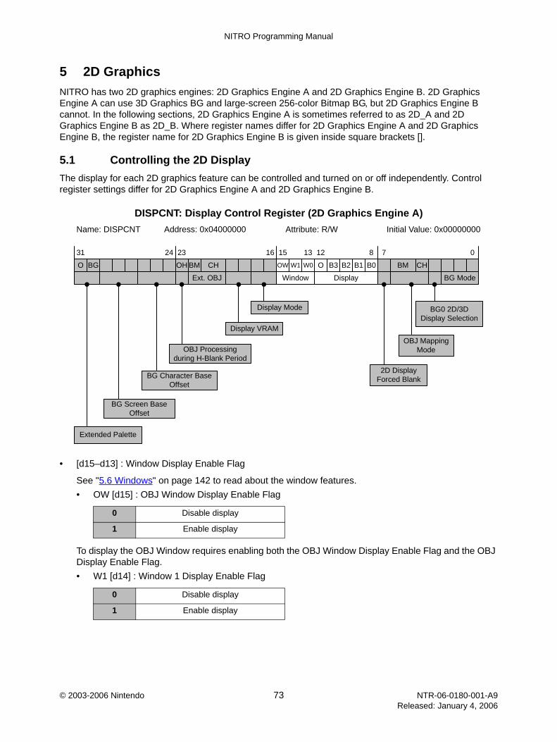
NITRO Programming Manual
5 2D GraphicsNITRO has two 2D graphics engines: 2D Graphics Engine A and 2D Graphics Engine B. 2D Graphics Engine A can use 3D Graphics BG and large-screen 256-color Bitmap BG, but 2D Graphics Engine B cannot. In the following sections, 2D Graphics Engine A is sometimes referred to as 2D_A and 2D Graphics Engine B as 2D_B. Where register names differ for 2D Graphics Engine A and 2D Graphics Engine B, the register name for 2D Graphics Engine B is given inside square brackets [].
5.1 Controlling the 2D DisplayThe display for each 2D graphics feature can be controlled and turned on or off independently. Control register settings differ for 2D Graphics Engine A and 2D Graphics Engine B.
DISPCNT: Display Control Register (2D Graphics Engine A)Name: DISPCNT Address: 0x04000000 Attribute: R/W Initial Value: 0x00000000
• [d15–d13] : Window Display Enable Flag
See "5.6 Windows" on page 142 to read about the window features.• OW [d15] : OBJ Window Display Enable Flag
To display the OBJ Window requires enabling both the OBJ Window Display Enable Flag and the OBJ Display Enable Flag.• W1 [d14] : Window 1 Display Enable Flag
0 Disable display
1 Enable display
0 Disable display
1 Enable display
O BG OH BM CH OW W1 W0 O B3 B2 B1 B0 BM CH
Ext. OBJ Window Display BG Mode
31 24 23 16 15 8 7 0
Extended Palette
BG Screen Base Offset
BG Character Base Offset
OBJ Processing during H-Blank Period
Display VRAM
Display Mode
2D Display Forced Blank
OBJ Mapping Mode
BG0 2D/3D Display Selection
1213
© 2003-2006 Nintendo 73 NTR-06-0180-001-A9Released: January 4, 2006

NITRO Programming Manual
• W0 [d13] : Window 0 Display Enable Flag
• [d12–d08] : Display Selection Flag• O [d12] : OBJ Display Enable Flag
• B3 [d11] : BG3 Display Enable Flag
• B2 [d10] : BG2 Display Enable Flag
• B1 [d09] : BG1 Display Enable Flag
• B0 [d08] : BG0 Display Enable Flag
0 Disable display
1 Enable display
0 Disable display
1 Enable display
0 Disable display
1 Enable display
0 Disable display
1 Enable display
0 Disable display
1 Enable display
0 Disable display
1 Enable display
NTR-06-0180-001-A9 74 © 2003-2006 NintendoReleased: January 4, 2006
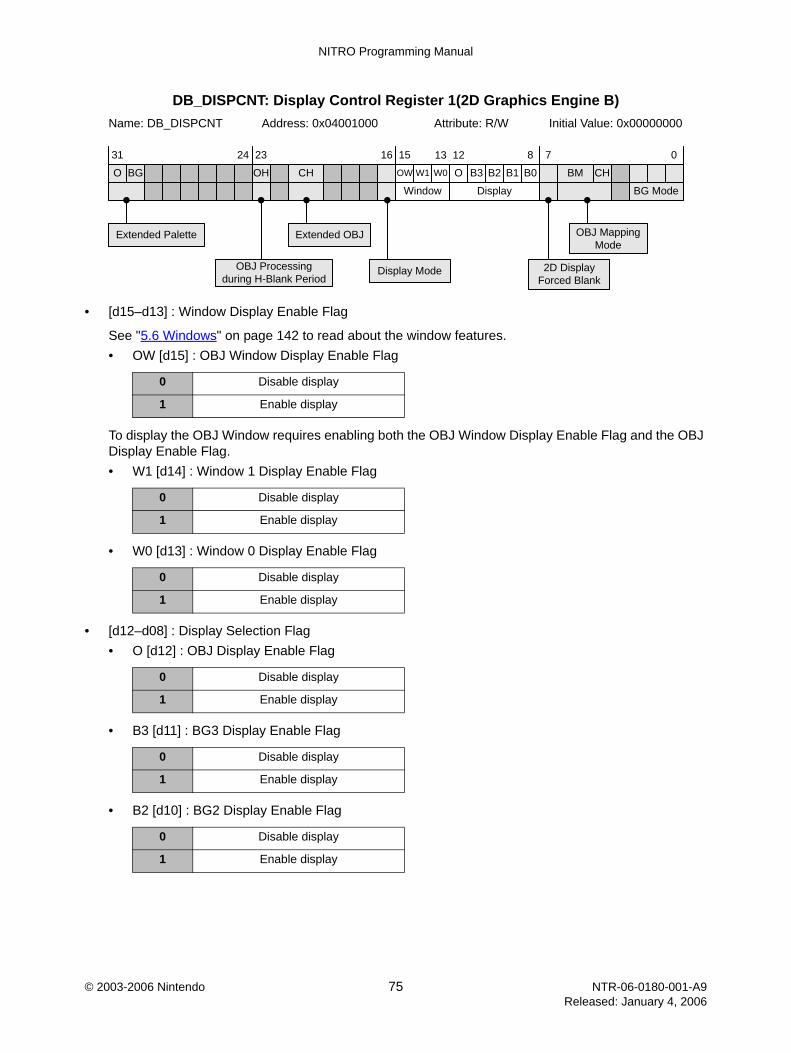
NITRO Programming Manual
DB_DISPCNT: Display Control Register 1(2D Graphics Engine B)Name: DB_DISPCNT Address: 0x04001000 Attribute: R/W Initial Value: 0x00000000
• [d15–d13] : Window Display Enable Flag
See "5.6 Windows" on page 142 to read about the window features.• OW [d15] : OBJ Window Display Enable Flag
To display the OBJ Window requires enabling both the OBJ Window Display Enable Flag and the OBJ Display Enable Flag.• W1 [d14] : Window 1 Display Enable Flag
• W0 [d13] : Window 0 Display Enable Flag
• [d12–d08] : Display Selection Flag• O [d12] : OBJ Display Enable Flag
• B3 [d11] : BG3 Display Enable Flag
• B2 [d10] : BG2 Display Enable Flag
0 Disable display
1 Enable display
0 Disable display
1 Enable display
0 Disable display
1 Enable display
0 Disable display
1 Enable display
0 Disable display
1 Enable display
0 Disable display
1 Enable display
O BG OH CH OW W1 W0 O B3 B2 B1 B0 BM CH
Window Display BG Mode
31 24 23 16 15 8 7 0
Extended Palette
OBJ Processing during H-Blank Period
Display Mode 2D Display Forced Blank
OBJ Mapping Mode
Extended OBJ
13 12
© 2003-2006 Nintendo 75 NTR-06-0180-001-A9Released: January 4, 2006

NITRO Programming Manual
• B1 [d09] : BG1 Display Enable Flag
• B0 [d08] : BG0 Display Enable Flag
0 Disable display
1 Enable display
0 Disable display
1 Enable display
NTR-06-0180-001-A9 76 © 2003-2006 NintendoReleased: January 4, 2006

NITRO Programming Manual
5.2 BG
5.2.1 BG ModeThe BG modes that can be set for 2D Graphics Engine A and 2D Graphics Engine B are different.
5.2.1.1 2D Graphics Engine AWith 2D Graphics Engine A, BG0 can be displayed as either 2D or 3D. In addition, Large-Screen 256-Color Bitmap BG can be selected as the BG type for BG2.
DISPCNT: Display Control Register (2D Graphics Engine A)Name: DISPCNT Address: 0x04000000 Attribute: R/W Initial Value: 0x00000000
• [d02–d00] : BG Mode
These bits set the BG mode number. The BG mode selects the BG types that can be used. See Table 5-1 for a list of BG modes for 2D Graphics Engine A.
The DISPCNT register can be used to select either Text BG or 3D BG as the BG type for BG0. See chapter "6 3D Graphics" on page 153 for details on 3D BG display.
Table 5-1: List of BG Modes (2D Graphics Engine A)BG Mode Number BG0 BG1 BG2 BG3
0 Text BG/3D BG Text BG Text BG Text BG
1 Text BG/3D BG Text BG Text BG Affine BG
2 Text BG/3D BG Text BG Affine BG Affine BG
3 Text BG/3D BG Text BG Text BG Affine Extended BG
4 Text BG/3D BG Text BG Affine BG Affine Extended BG
5 Text BG/3D BG Text BG Affine Extended BG Affine Extended BG
6 3D BG — Large-Screen256-Color Bitmap BG —
7 Prohibited Setting
O BG OH BM CH OW W1 W0 O B3 B2 B1 B0 BM CH
Ext. OBJ Window Display BG Mode
31 24 23 16 15 8 7 0
Extended Palette
BG Screen Base Offset
BG Character Base Offset
OBJ Processing during H-Blank Period
Display VRAM
Display Mode
2D Display Forced Blank
OBJ Mapping Mode
BG0 2D/3D Display Selection
2
© 2003-2006 Nintendo 77 NTR-06-0180-001-A9Released: January 4, 2006
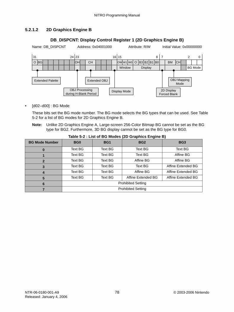
NITRO Programming Manual
5.2.1.2 2D Graphics Engine B
DB_DISPCNT: Display Control Register 1 (2D Graphics Engine B)Name: DB_DISPCNT Address: 0x04001000 Attribute: R/W Initial Value: 0x00000000
• [d02–d00] : BG Mode
These bits set the BG mode number. The BG mode selects the BG types that can be used. See Table 5-2 for a list of BG modes for 2D Graphics Engine B.
Note: Unlike 2D Graphics Engine A, Large-screen 256-Color Bitmap BG cannot be set as the BG type for BG2. Furthermore, 3D BG display cannot be set as the BG type for BG0.
Table 5-2 : List of BG Modes (2D Graphics Engine B)BG Mode Number BG0 BG1 BG2 BG3
0 Text BG Text BG Text BG Text BG
1 Text BG Text BG Text BG Affine BG
2 Text BG Text BG Affine BG Affine BG
3 Text BG Text BG Text BG Affine Extended BG
4 Text BG Text BG Affine BG Affine Extended BG
5 Text BG Text BG Affine Extended BG Affine Extended BG
6 Prohibited Setting
7 Prohibited Setting
O BG OH CH OW W1 W0 O B3 B2 B1 B0 BM CH
Window Display BG Mode
31 24 23 16 15 8 7 0
Extended Palette
OBJ Processing during H-Blank Period
Display Mode 2D Display Forced Blank
OBJ Mapping Mode
Extended OBJ
2
NTR-06-0180-001-A9 78 © 2003-2006 NintendoReleased: January 4, 2006

NITRO Programming Manual
5.2.1.3 Basic Features for Each Type of BGEach BG type has its own special features described in Table 5-3.
Table 5-3 : Basic Features of BG TypesBG Type Features
3D BGThis type can display images generated by the 3D graphics engine.
It can be displayed with other BG screens according to alpha-blending and priority settings.2D Graphics Engine B cannot use this type.
Text BGThis type is a character format BG.
Text BG is the only BG type that can handle characters defined in 16 colors and control VRAM consumption, but it cannot accommodate affine transformations.
Affine BG This type is the character format BG that can accommodate affine transformations.It cannot perform character-unit processes (such as HV Flips).
Affine Extended BG
Three types are available:• Character BG that can use 256 colors x 16 palettes• 256-Color Bitmap BG• Direct Color Bitmap BG that can specify color directly
Large-Screen256-Color Bitmap BG
This type is the Large-Screen Bitmap BG.Because one screen makes full use of the maximum capacity of BG-VRAM (512 KB), it
cannot be used together with other BGs. However, it can be used together with a 3D screen.2D Graphics Engine B cannot use this type.
© 2003-2006 Nintendo 79 NTR-06-0180-001-A9Released: January 4, 2006

NITRO Programming Manual
5.2.1.4 Specifications for Different BG TypesThe specifications for the different types of BG are shown in Table 5-4.
Table 5-4 : Specifications for BG types
Note: 2D Graphics Engine B cannot set 3D BG and Large-Screen 256-Color Bitmap BG as BG types.
Note: Because the allocation of BG-VRAM to 2D Graphics Engine B is limited, the following settings cannot be used:• 256-Color Bitmap: 512x512• Direct Color Bitmap: 512x256 and 512x512
Category Character BG Bitmap BG
BG Type
Specs
3DBG Text BG Affine BG
Affine Extended BG Large-Screen 256-
Color Bitmap BG
256-Color x 16 Palettes 256-Color Direct
Color
Screen Size 256x192
256x256512x256256x512512x512
128x128256x256512x512
1,024x1,024
128x128256x256512x512
1,024x1,024
128x128256x256512x256512x512
128x128256x256512x256512x512
512x1,0241,024x512
Specifiable Character Count — 1,024 256 1,024 — — —
Number of Colors/Palettes 262,144
16/16256/1
256/16256/1 256/16 256/1 32,768 256/1
Affine X X X X X
HV Flip X X
H Scroll X X X X X X X
V Scroll X X X X X X
Mosaic X X X X X X
Fade-in/Fade-out X X X X X X X
Alpha Blending X X X X X X X
Priority X X X X X X X
NTR-06-0180-001-A9 80 © 2003-2006 NintendoReleased: January 4, 2006
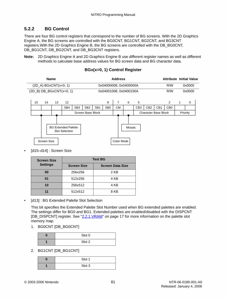
NITRO Programming Manual
5.2.2 BG ControlThere are four BG control registers that correspond to the number of BG screens. With the 2D Graphics Engine A, the BG screens are controlled with the BG0CNT, BG1CNT, BG2CNT, and BG3CNT registers.With the 2D Graphics Engine B, the BG screens are controlled with the DB_BG0CNT, DB_BG1CNT, DB_BG2CNT, and DB_BG3CNT registers.
Note: 2D Graphics Engine A and 2D Graphics Engine B use different register names as well as different methods to calculate base address values for BG screen data and BG character data.
BGx(x=0, 1) Control Register
• [d15–d14] : Screen Size
• [d13] : BG Extended Palette Slot Selection
This bit specifies the Extended Palette Slot Number used when BG extended palettes are enabled. The settings differ for BG0 and BG1. Extended palettes are enabled/disabled with the DISPCNT [DB_DISPCNT] register. See "2.2.1 VRAM" on page 17 for more information on the palette slot memory map.1. BG0CNT [DB_BG0CNT]
2. BG1CNT [DB_BG1CNT]
Name Address Attribute Initial Value
(2D_A) BGxCNT(x=0, 1) 0x04000008, 0x0400000A R/W 0x0000
(2D_B) DB_BGxCNT(x=0, 1) 0x04001008, 0x0400100A R/W 0x0000
Screen Size Settings
Text BG
Screen Size Screen Data Size
00 256x256 2 KB
01 512x256 4 KB
10 256x512 4 KB
11 512x512 8 KB
0 Slot 0
1 Slot 2
0 Slot 1
1 Slot 3
SB4 SB3 SB2 SB1 SB0 CM CB3 CB2 CB1 CB0
Screen Base Block Character Base Block Priority
15 8 7 0
Screen Size
BG Extended Palette Slot Selection
Color Mode
Mosaic
14 13 12 6 5 2 1
© 2003-2006 Nintendo 81 NTR-06-0180-001-A9Released: January 4, 2006

NITRO Programming Manual
• SB4-SB0 [d12–d08] : Screen Base Block
These bits specify (in 2-KB units) the starting block in VRAM where screen data is stored. When screen data is actually referenced, the starting address is calculated as follows.
2D Graphics Engine A
The starting address is the sum of the DISPCNT register's screen base offset value with a 64-KB offset and the screen base block with a 2-KB offset.
(screen base offset x 0x10000) + (screen base block x 0x800)
2D Graphics Engine B
The starting address is the screen base block with a 2-KB offset.
(screen base block x 0x800)
• CM [d07] : Color Mode
This bit specifies whether the screen data references BG character data in 16-color or 256-color format.
• [d06] : Mosaic
This bit controls whether the mosaic process for BG is on or off. Set the mosaic size with the MOSAIC [DB_MOSAIC] register.
• CB3-CB0 [d05–d02] : Character Base Block
These bits specify (in 16-KB units) the starting block in VRAM for storing character data. When character data is actually referenced, the starting address is calculated as follows.
2D Graphics Engine A
The starting address is the sum of the DISPCNT register's character base offset value with a 64-KB offset and the character base block with a 16-KB offset.
(character base offset x 0x10000) + (character base block x 0x4000)
2D Graphics Engine B
The starting address is the character base block with a 16-KB offset.
(character base block x 0x4000)
• [d01–d00] : Priority
The default order of priority among the BG screens is BG0 > BG1 > BG2 > BG3 (when priority settings are the same). However, this order can be changed. Priorities of 0 (highest) to 3 (lowest) can be set. Be careful of the pixel specifications to which color special effects are applied when changing BG priorities.
0 16-color mode
1 256-color mode
NTR-06-0180-001-A9 82 © 2003-2006 NintendoReleased: January 4, 2006
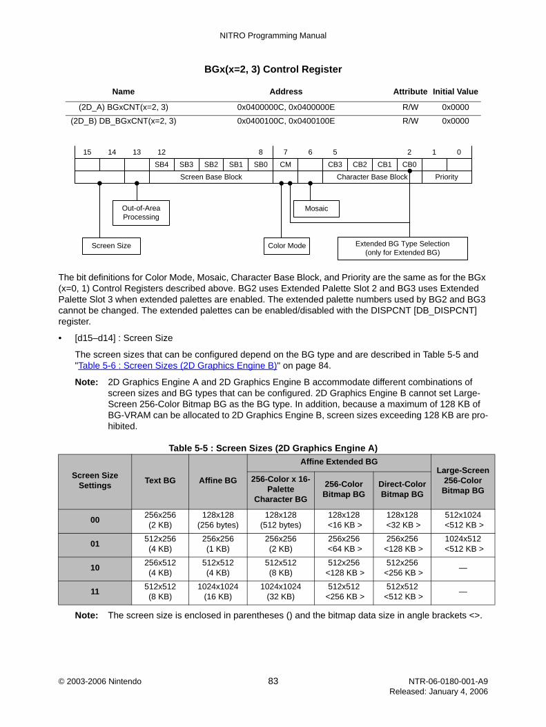
NITRO Programming Manual
BGx(x=2, 3) Control Register
The bit definitions for Color Mode, Mosaic, Character Base Block, and Priority are the same as for the BGx (x=0, 1) Control Registers described above. BG2 uses Extended Palette Slot 2 and BG3 uses Extended Palette Slot 3 when extended palettes are enabled. The extended palette numbers used by BG2 and BG3 cannot be changed. The extended palettes can be enabled/disabled with the DISPCNT [DB_DISPCNT] register.
• [d15–d14] : Screen Size
The screen sizes that can be configured depend on the BG type and are described in Table 5-5 and "Table 5-6 : Screen Sizes (2D Graphics Engine B)" on page 84.
Note: 2D Graphics Engine A and 2D Graphics Engine B accommodate different combinations of screen sizes and BG types that can be configured. 2D Graphics Engine B cannot set Large-Screen 256-Color Bitmap BG as the BG type. In addition, because a maximum of 128 KB of BG-VRAM can be allocated to 2D Graphics Engine B, screen sizes exceeding 128 KB are pro-hibited.
Table 5-5 : Screen Sizes (2D Graphics Engine A)
Note: The screen size is enclosed in parentheses () and the bitmap data size in angle brackets <>.
Name Address Attribute Initial Value
(2D_A) BGxCNT(x=2, 3) 0x0400000C, 0x0400000E R/W 0x0000
(2D_B) DB_BGxCNT(x=2, 3) 0x0400100C, 0x0400100E R/W 0x0000
Screen Size Settings Text BG Affine BG
Affine Extended BGLarge-Screen
256-Color Bitmap BG
256-Color x 16-Palette
Character BG
256-Color Bitmap BG
Direct-Color Bitmap BG
00 256x256(2 KB)
128x128(256 bytes)
128x128(512 bytes)
128x128 <16 KB >
128x128 <32 KB >
512x1024 <512 KB >
01 512x256(4 KB)
256x256(1 KB)
256x256(2 KB)
256x256 <64 KB >
256x256 <128 KB >
1024x512 <512 KB >
10 256x512(4 KB)
512x512(4 KB)
512x512(8 KB)
512x256 <128 KB >
512x256 <256 KB > —
11 512x512(8 KB)
1024x1024(16 KB)
1024x1024(32 KB)
512x512 <256 KB >
512x512 <512 KB > —
SB4 SB3 SB2 SB1 SB0 CM CB3 CB2 CB1 CB0
Screen Base Block Character Base Block Priority
15 8 7 0
Screen Size
Out-of-Area Processing
Color Mode
Mosaic
14 13 12 6 5 2 1
Extended BG Type Selection(only for Extended BG)
© 2003-2006 Nintendo 83 NTR-06-0180-001-A9Released: January 4, 2006
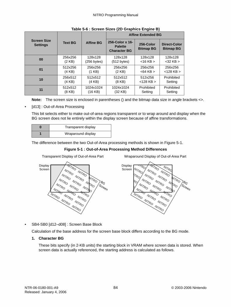
NITRO Programming Manual
Table 5-6 : Screen Sizes (2D Graphics Engine B)
Note: The screen size is enclosed in parentheses () and the bitmap data size in angle brackets <>.
• [d13] : Out-of-Area Processing
This bit selects either to make out-of-area regions transparent or to wrap around and display when the BG screen does not lie entirely within the display screen because of affine transformations.
The difference between the two Out-of-Area processing methods is shown in Figure 5-1.
Figure 5-1 : Out-of-Area Processing Method Differences
• SB4-SB0 [d12–d08] : Screen Base Block
Calculation of the base address for the screen base block differs according to the BG mode.
1. Character BG
These bits specify (in 2-KB units) the starting block in VRAM where screen data is stored. When screen data is actually referenced, the starting address is calculated as follows.
Screen Size Settings Text BG Affine BG
Affine Extended BG
256-Color x 16-Palette
Character BG
256-Color Bitmap BG
Direct-Color Bitmap BG
00 256x256(2 KB)
128x128(256 bytes)
128x128(512 bytes)
128x128 <16 KB >
128x128 <32 KB >
01 512x256(4 KB)
256x256(1 KB)
256x256(2 KB)
256x256 <64 KB >
256x256 <128 KB >
10 256x512(4 KB)
512x512(4 KB)
512x512(8 KB)
512x256 <128 KB >
Prohibited Setting
11 512x512(8 KB)
1024x1024(16 KB)
1024x1024(32 KB)
Prohibited Setting
Prohibited Setting
0 Transparent display
1 Wraparound display
NITRO NITRO NITRO
NITRO NITRO NITRO
NITRO NITRO NITRO
NITRO NITRO NITRO
NITRO NITRO NITRO
NITRO NITRO NITRO
NITRO NITRO NITRO
NITRO NITRO NITRO
NITRO NITRO NITRO
NITRO NITRO NITRO
NITRO NITRO NITRO
NITRO NITRO NITRO
NITRO NITRO NITRO
NITRO NITRO NITRO
Transparent Display of Out-of-Area Part Wraparound Display of Out-of-Area Part
DisplayScreen
BGScreen
BGScreen
DisplayScreen
NITRO NITRO NITRO
NITRO NITRO NITRO
NITRO NITRO NITRO
NITRO NITRO NITRO
NITRO NITRO NITRO
NITRO NITRO NITRO
NITRO NITRO NITRO
NTR-06-0180-001-A9 84 © 2003-2006 NintendoReleased: January 4, 2006
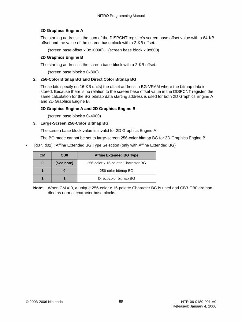
NITRO Programming Manual
2D Graphics Engine A
The starting address is the sum of the DISPCNT register's screen base offset value with a 64-KB offset and the value of the screen base block with a 2-KB offset.
(screen base offset x 0x10000) + (screen base block x 0x800)
2D Graphics Engine B
The starting address is the screen base block with a 2-KB offset.
(screen base block x 0x800)
2. 256-Color Bitmap BG and Direct Color Bitmap BG
These bits specify (in 16-KB units) the offset address in BG-VRAM where the bitmap data is stored. Because there is no relation to the screen base offset value in the DISPCNT register, the same calculation for the BG bitmap data starting address is used for both 2D Graphics Engine A and 2D Graphics Engine B.
2D Graphics Engine A and 2D Graphics Engine B
(screen base block x 0x4000)
3. Large-Screen 256-Color Bitmap BG
The screen base block value is invalid for 2D Graphics Engine A.
The BG mode cannot be set to large-screen 256-color bitmap BG for 2D Graphics Engine B.
• [d07, d02] : Affine Extended BG Type Selection (only with Affine Extended BG)
Note: When CM = 0, a unique 256-color x 16-palette Character BG is used and CB3-CB0 are han-dled as normal character base blocks.
CM CB0 Affine Extended BG Type
0 (See note) 256-color x 16-palette Character BG
1 0 256-color bitmap BG
1 1 Direct-color bitmap BG
© 2003-2006 Nintendo 85 NTR-06-0180-001-A9Released: January 4, 2006
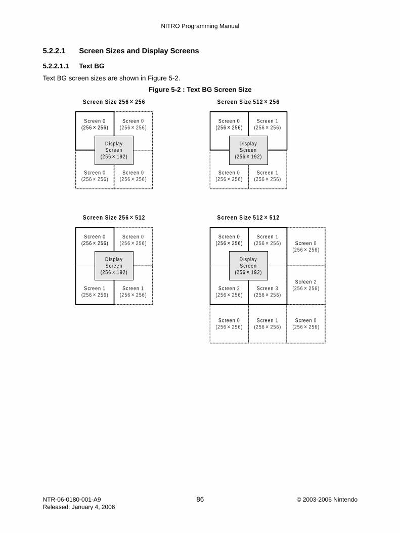
NITRO Programming Manual
5.2.2.1 Screen Sizes and Display Screens
5.2.2.1.1 Text BG
Text BG screen sizes are shown in Figure 5-2.
Figure 5-2 : Text BG Screen Size
Screen 0(256× 256)
Screen 0(256× 256)
Screen 0(256× 256)
Screen 0(256× 256)
D isplayScreen
(256× 192)
Screen S ize 256× 256 Screen S ize 512× 256
Screen S ize 256× 512 Screen S ize 512× 512
Screen 0(256× 256)
Screen 1(256× 256)
Screen 1(256× 256)
Screen 0(256× 256)
D isplayScreen
(256× 192)
Screen 1(256× 256)
Screen 1(256× 256)
Screen 0(256× 256)
Screen 0(256× 256)
D isplayScreen
(256× 192)
Screen 1(256× 256)
Screen 3(256× 256)
Screen 2(256× 256)
Screen 0(256× 256)
D isplayScreen
(256× 192)
Screen 0(256× 256)
Screen 2(256× 256)
Screen 1(256× 256)
Screen 0(256× 256)
Screen 0(256× 256)
NTR-06-0180-001-A9 86 © 2003-2006 NintendoReleased: January 4, 2006

NITRO Programming Manual
5.2.2.1.2 Affine BG
Affine BG screen sizes are shown in Figure 5-3.
Figure 5-3 : Affine BG Screen Size
Screen 0or
Transparent
Screen 0or Transparent
Screen Size 128×128 Screen Size 256×256
Screen Size 512×512Screen Size 1024×1024
Screen 0(128×128)
Screen 0or
TransparentDisplayScreen
(256×192)
Screen 0or
Transparent
Screen 0or
Transparent
Screen 0or
Transparent
Screen 0(256×256)
DisplayScreen
(256×192)
Screen 0or Transparent
Screen 0or Transparent
Screen 0or Transparent
Screen 0(512×512)
DisplayScreen
(256×192)
Screen 0or Transparent
Screen 0(1024×1024)
DisplayScreen
(256×192)
© 2003-2006 Nintendo 87 NTR-06-0180-001-A9Released: January 4, 2006
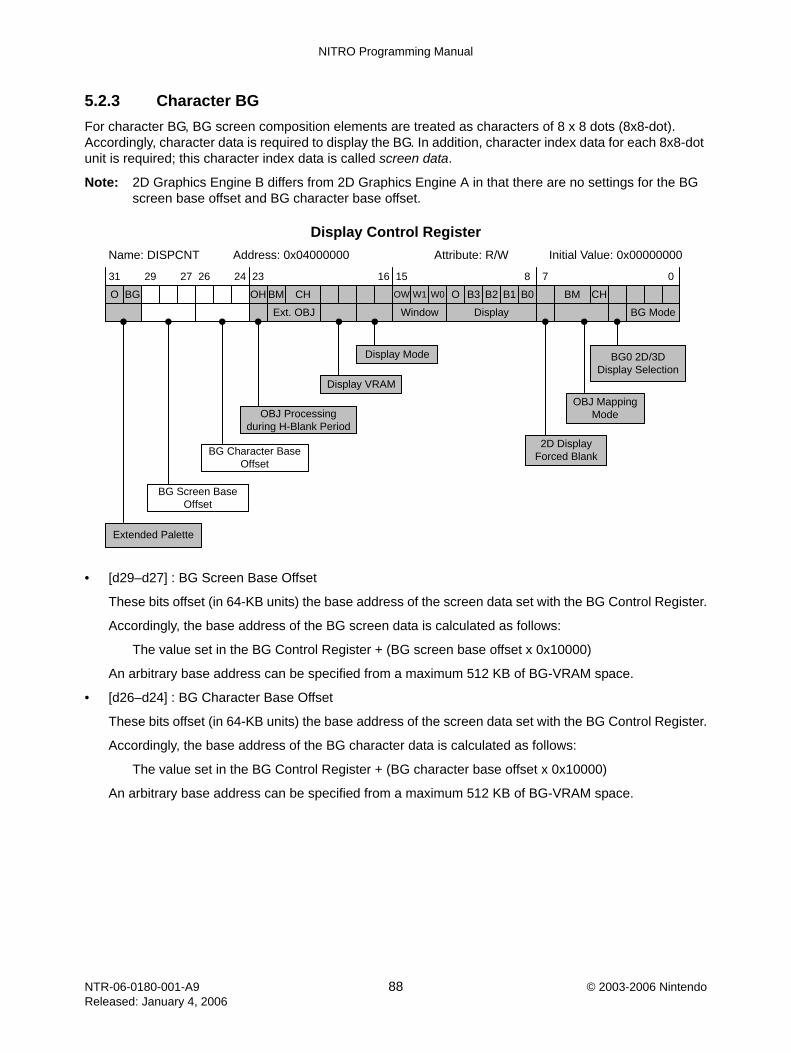
NITRO Programming Manual
5.2.3 Character BGFor character BG, BG screen composition elements are treated as characters of 8 x 8 dots (8x8-dot). Accordingly, character data is required to display the BG. In addition, character index data for each 8x8-dot unit is required; this character index data is called screen data.
Note: 2D Graphics Engine B differs from 2D Graphics Engine A in that there are no settings for the BG screen base offset and BG character base offset.
Display Control Register Name: DISPCNT Address: 0x04000000 Attribute: R/W Initial Value: 0x00000000
• [d29–d27] : BG Screen Base Offset
These bits offset (in 64-KB units) the base address of the screen data set with the BG Control Register.
Accordingly, the base address of the BG screen data is calculated as follows:
The value set in the BG Control Register + (BG screen base offset x 0x10000)
An arbitrary base address can be specified from a maximum 512 KB of BG-VRAM space.
• [d26–d24] : BG Character Base Offset
These bits offset (in 64-KB units) the base address of the screen data set with the BG Control Register.
Accordingly, the base address of the BG character data is calculated as follows:
The value set in the BG Control Register + (BG character base offset x 0x10000)
An arbitrary base address can be specified from a maximum 512 KB of BG-VRAM space.
O BG OH BM CH OW W1 W0 O B3 B2 B1 B0 BM CH
Ext. OBJ Window Display BG Mode
31 24 23 16 15 8 7 0
Extended Palette
BG Screen Base Offset
BG Character Base Offset
OBJ Processing during H-Blank Period
Display VRAM
Display Mode
2D Display Forced Blank
OBJ Mapping Mode
BG0 2D/3D Display Selection
29 27 26
NTR-06-0180-001-A9 88 © 2003-2006 NintendoReleased: January 4, 2006

NITRO Programming Manual
5.2.3.1 VRAM Maps of BG DataCharacter BG requires both BG screen data and BG character data. Store both the BG screen data and the BG character data in VRAM that was allocated to BG-VRAM by the RAM Bank Control Register. BG-VRAM can be assigned up to a maximum of 512 KB with 2D Graphics Engine A and up to a maximum of 128 KB with 2D Graphics Engine B.1. BG Character Data
With 2D Graphics Engine A, the starting address for referencing BG character data can be set by specifying the DISPCNT register's character base offset and the BG Control register's character base block. With 2D Graphics Engine B, there is no setting for character base offset. The VRAM offset for BG character data is shown in Figure 5-4.
The volume of data depends on the amount of registered character data and the format (Color Mode: 256 or 16 colors).
Figure 5-4 : VRAM Offset for BG Character Data
Note: For 2D Graphics Engine A, the maximum amount of VRAM that can be used for BG character data is 256 KB because the DISPCNT register's base offset cannot be set for each BG screen.
For 2D Graphics Engine B, the maximum amount of VRAM that can be used for BG character data is 128 KB because there are limitations on the size of BG-VRAM that can be allocated.
BG Character Data Base Blocks
Base Offset 3
Base Offset 2
Base Offset 1
Base Offset 0
Base Offset 7
Base Offset 6
Base Offset 5
Base Offset 4
0x00000
0x10000
0x20000
0x30000
0x40000
0x50000
0x60000
0x70000
0x80000
Base Block 3
Base Block 2
Base Block 1
Base Block 0
Base Offset in VRAM
Base Block 7
Base Block 6
Base Block 5
Base Block 4
0000h
4000h
8000h
C000h
20000h
1C000h
18000h
14000h
10000h
Base Block 11
Base Block 10
Base Block 9
Base Block 8
Base Block 15
Base Block 14
Base Block 13
Base Block 12
24000h
28000h
2C000h
30000h
40000h
3C000h
38000h
34000h
© 2003-2006 Nintendo 89 NTR-06-0180-001-A9Released: January 4, 2006

NITRO Programming Manual
2. BG Screen Data
For 2D Graphics Engine A, the starting address for referencing BG screen data can be set by specifying the DISPCNT register's screen base offset and the BG Control register's screen base block. With 2D Graphics Engine B, there is no setting for the screen base offset. The VRAM offset for BG screen data is shown in Figure 5-5.
The volume of data depends on the BG type (Text BG or Affine BG) and the screen size.
Figure 5-5 : VRAM Offset for BG Screen Data
Note: For 2D Graphics Engine A, the maximum amount of VRAM that can be used for BG screen data is 64 KB because the DISPCNT register's base offset cannot be set for each BG screen.
With 2D Graphics Engine B, the maximum amount of VRAM that can be used for BG screen data is 64 KB.
BG Screen Data Base Blocks
Base Offset 3
Base Offset 2
Base Offset 1
Base Offset 0
Base Offset 7
Base Offset 6
Base Offset 5
Base Offset 4
0x00000
0x10000
0x20000
0x30000
0x40000
0x50000
0x60000
0x70000
0x80000
Base Block 0
Base Block 7
Base Block 8
Base Block 15
Base Block 16
Base Block 23
Base Block 24
Base Block 31
Base Offsets in VRAM
800h
3800h
4800h
7800h
8800h
B800h
C800h
F800h
4000h
8000h
C000h
10000h
000h
NTR-06-0180-001-A9 90 © 2003-2006 NintendoReleased: January 4, 2006

NITRO Programming Manual
5.2.3.2 Text BG
5.2.3.2.1 Screen Data Format
Store the BG screen data starting from the starting address of the BG screen base block specified by the BG Control Register. BG screen data for Text BG screens is configured using the following format:
Text BG Screen Data
• [d15–d12] : Color Palette
Palettes applied to characters are specified in the range of 0-15. The Color Palette specification is enabled with 256 colors x 16 palettes or 16 colors x 16 palettes, but it is disabled with 256 colors x 1 palette.
• [d11–d10] : Flip• VF: Vertical Flip Flag HF: Horizontal Flip Flag
• [d09–d00] : Character Name
These bits specify the character number of the character that serves as the origin of the starting address for the character base block specified by the BG Control Register.
0 Do not flip
1 Flip
VF HF
Color Palette Flip Character Name
15 12 11 10 9 8 7 0
© 2003-2006 Nintendo 91 NTR-06-0180-001-A9Released: January 4, 2006
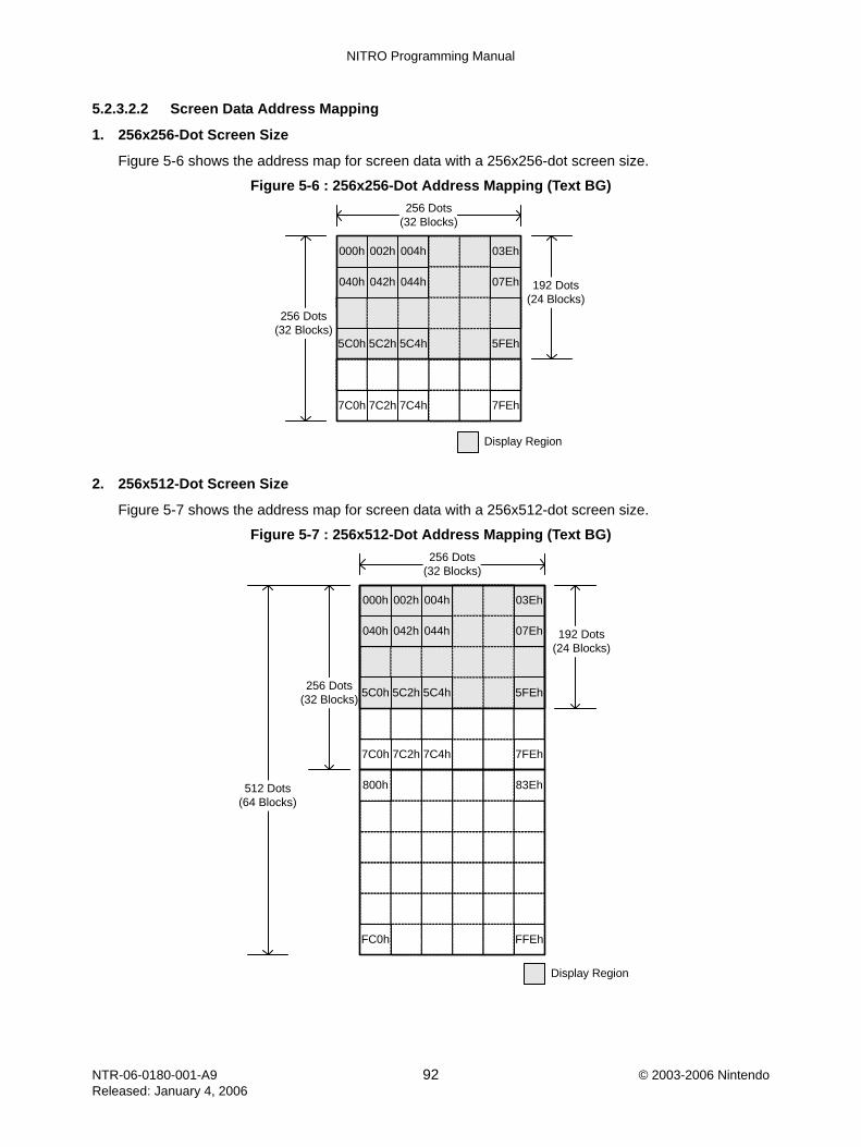
NITRO Programming Manual
5.2.3.2.2 Screen Data Address Mapping
1. 256x256-Dot Screen Size
Figure 5-6 shows the address map for screen data with a 256x256-dot screen size.
Figure 5-6 : 256x256-Dot Address Mapping (Text BG)
2. 256x512-Dot Screen Size
Figure 5-7 shows the address map for screen data with a 256x512-dot screen size.
Figure 5-7 : 256x512-Dot Address Mapping (Text BG)
192 Dots(24 Blocks)
000h 002h
7C0h 7C2h 7C4h 7FEh
256 Dots(32 Blocks)
256 Dots(32 Blocks)
040h 042h 044h
004h
07Eh
03Eh
5C0h 5C2h 5C4h 5FEh
Display Region
192 Dots(24 Blocks)
000h 002h
7C0h 7C2h 7C4h 7FEh
800h 83Eh
FC0h FFEh
256 Dots(32 Blocks)
256 Dots(32 Blocks)
512 Dots(64 Blocks)
040h 042h 044h
004h
07Eh
03Eh
5C0h 5C2h 5C4h 5FEh
Display Region
NTR-06-0180-001-A9 92 © 2003-2006 NintendoReleased: January 4, 2006
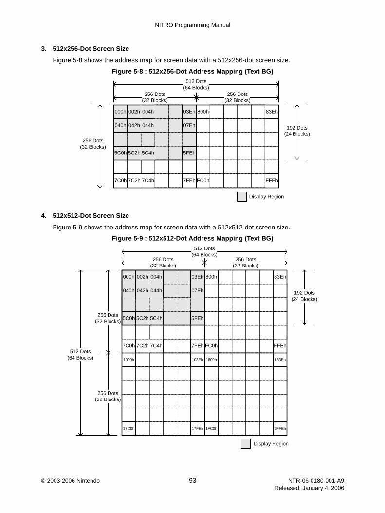
NITRO Programming Manual
3. 512x256-Dot Screen Size
Figure 5-8 shows the address map for screen data with a 512x256-dot screen size.
Figure 5-8 : 512x256-Dot Address Mapping (Text BG)
4. 512x512-Dot Screen Size
Figure 5-9 shows the address map for screen data with a 512x512-dot screen size.
Figure 5-9 : 512x512-Dot Address Mapping (Text BG)
000h 002h
7C0h 7C2h 7C4h 7FEh
256 Dots(32 Blocks)
256 Dots(32 Blocks)
040h 042h 044h
004h
07Eh
03Eh
5C0h 5C2h 5C4h 5FEh
800h
FC0h FFEh
83Eh
512 Dots(64 Blocks)
256 Dots(32 Blocks)
Display Region
192 Dots(24 Blocks)
256 Dots(32 Blocks)
256 Dots(32 Blocks)
512 Dots(64 Blocks)
000h 002h
7C0h 7C2h 7C4h 7FEh
256 Dots(32 Blocks)
040h 042h 044h
004h
07Eh
03Eh
5C0h 5C2h 5C4h 5FEh
Display Region
800h
FC0h FFEh
83Eh
512 Dots(64 Blocks)
256 Dots(32 Blocks)
1000h
17C0h 17FEh
103Eh 1800h
1FFEh
183Eh
1FC0h
192 Dots(24 Blocks)
© 2003-2006 Nintendo 93 NTR-06-0180-001-A9Released: January 4, 2006

NITRO Programming Manual
5.2.3.2.3 Character Data Formats
The character data formats for Text BG 16-color mode and Text BG 256-color mode are shown below. The Character Display table shows the case when an 8x8-dot character is defined.
5.2.3.2.3.1 16-Color Mode
The character data format for 16-color mode, correspondence between character display and pixel data, and address mapping (Figure 5-10) are shown below.
16-Color Mode Character Data Format
Character Display
Figure 5-10 : Character Data Address Mapping (Text BG 16-Color Mode)
P0 P1 P2 P3
P3 P2 P1 P0
4 pixels worth of data (4 bits/pixel)
15 12 11 8 7 4 3 0
4 bits of data for each dot(specifies 1 of 16 colors)
d4
d5
d6
d7
d0
d1
d2
d3
d4
d5
d6
d7
d0
d1
d2
d3
d4
d5
d6
d7
d0
d1
d2
d3
d4
d5
d6
d7
d0
d1
d2
d3
Byte 0
4
8
28
20
16
12
24
1
5
9
29
13
17
21
25
2
6
10
14
18
22
26
30
3
7
11
15
19
23
27
31
8 Dots
8 Dots
NTR-06-0180-001-A9 94 © 2003-2006 NintendoReleased: January 4, 2006
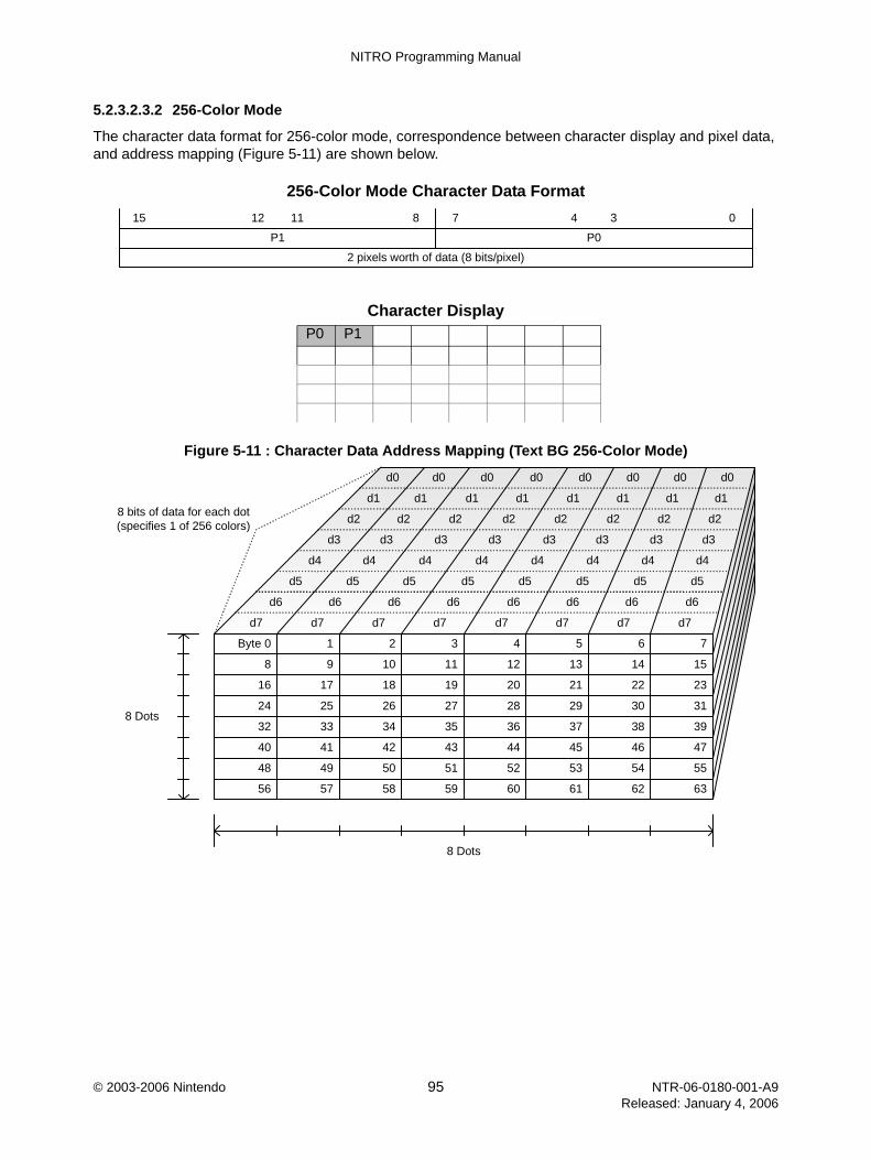
NITRO Programming Manual
5.2.3.2.3.2 256-Color Mode
The character data format for 256-color mode, correspondence between character display and pixel data, and address mapping (Figure 5-11) are shown below.
256-Color Mode Character Data Format
Character Display
Figure 5-11 : Character Data Address Mapping (Text BG 256-Color Mode)
P0 P1
P1 P0
2 pixels worth of data (8 bits/pixel)
15 12 11 8 7 4 3 0
4
12
20
28
36
44
52
60
5
13
21
29
37
45
53
61
6
14
22
30
38
46
54
62
7
15
23
31
39
47
55
63
Byte 0
8
16
24
32
40
48
56
1
9
17
25
33
41
49
57
2
10
18
26
34
42
50
58
3
11
19
27
35
43
51
59
8 bits of data for each dot(specifies 1 of 256 colors)
d0
d1
d4
d2
d3
d5
d6
d7
d0
d1
d4
d2
d3
d5
d6
d7
d0
d1
d4
d2
d3
d5
d6
d7
d0
d1
d4
d2
d3
d5
d6
d7
d0
d1
d4
d2
d3
d5
d6
d7
d0
d1
d4
d2
d3
d5
d6
d7
d0
d1
d4
d2
d3
d5
d6
d7
d0
d1
d4
d2
d3
d5
d6
d7
8 Dots
8 Dots
© 2003-2006 Nintendo 95 NTR-06-0180-001-A9Released: January 4, 2006

NITRO Programming Manual
5.2.3.3 Affine BGThis character format BG type can be rotated and scaled.
Note: Affine BG can be set only with BG2 and BG3. The color mode for Affine BG screens is fixed to 256-color mode. Consequently, the BG Control Register's color-mode setting is disabled. Furthermore, horizontal and vertical flips cannot be performed on Affine BG.
5.2.3.3.1 Screen Data Format
Store the BG screen data starting from the starting address of the BG screen base block specified by the BG Control register.
BG screen data for Affine BG screens is configured using the following format:
Affine BG Screen Data
• [d07–d00] : Character Name
These bits specify the character number of the character that serves as the origin of the starting address for the character base block specified by the BG Control Register.
Character Name
7 0
NTR-06-0180-001-A9 96 © 2003-2006 NintendoReleased: January 4, 2006
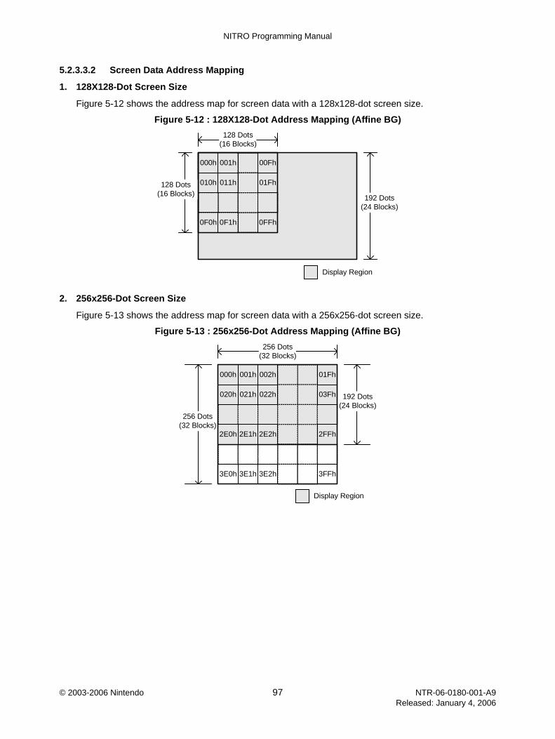
NITRO Programming Manual
5.2.3.3.2 Screen Data Address Mapping
1. 128X128-Dot Screen Size
Figure 5-12 shows the address map for screen data with a 128x128-dot screen size.
Figure 5-12 : 128X128-Dot Address Mapping (Affine BG)
2. 256x256-Dot Screen Size
Figure 5-13 shows the address map for screen data with a 256x256-dot screen size.
Figure 5-13 : 256x256-Dot Address Mapping (Affine BG)
192 Dots(24 Blocks)
000h 001h
128 Dots(16 Blocks)
128 Dots(16 Blocks)
010h 011h 01Fh
00Fh
0F0h 0F1h 0FFh
Display Region
192 Dots(24 Blocks)
000h 001h
3E0h 3E1h 3E2h 3FFh
256 Dots(32 Blocks)
256 Dots(32 Blocks)
020h 021h 022h
002h
03Fh
01Fh
2E0h 2E1h 2E2h 2FFh
Display Region
© 2003-2006 Nintendo 97 NTR-06-0180-001-A9Released: January 4, 2006

NITRO Programming Manual
3. 512x512-Dot Screen Size
Figure 5-14 shows the address map for screen data with a 512x512-dot screen size.
Figure 5-14 : 512x512-Dot Address Mapping (Affine BG)
192 Dots(24 Blocks)
7FFh
020h000h 001h
512 Dots(64 Blocks)
040h 041h 042h
002h
05Fh
01Fh
5C0h 5C1h 5C2h 5DFh
Display Region
03Fh
07Fh
5FFh
060h
5E0h
7C0h 7C1h 7C2h 7DFh 7E0h
FFFhFC0h FC1h FC2h FDFh FE0h
83Fh820h800h 81Fh801h 802h
256 Dots(32 Blocks)
512 Dots(64 Blocks)
NTR-06-0180-001-A9 98 © 2003-2006 NintendoReleased: January 4, 2006
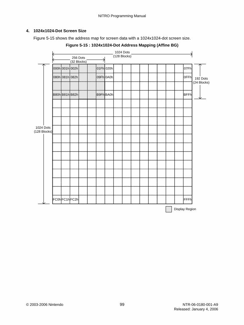
NITRO Programming Manual
4. 1024x1024-Dot Screen Size
Figure 5-15 shows the address map for screen data with a 1024x1024-dot screen size.
Figure 5-15 : 1024x1024-Dot Address Mapping (Affine BG)
192 Dots(24 Blocks)
020h000h 001h
1024 Dots(128 Blocks)
1024 Dots(128 Blocks)
080h 081h 082h
002h
09Fh
01Fh
B80h B81h B82h B9Fh
Display Region
07Fh
BFFh
0A0h
BA0h
0FFh
FFFhFC0h FC1h FC2h
256 Dots(32 Blocks)
© 2003-2006 Nintendo 99 NTR-06-0180-001-A9Released: January 4, 2006

NITRO Programming Manual
5.2.3.3.3 Character Data Format
The character data format for Affine BG screens is shown below. The Character Display table shows the case when an 8x8-dot character is defined. Figure 5-16 shows the character data address mapping.
Character Data Format
Character Display
Figure 5-16 : Character Data Address Mapping (Affine BG)
P0 P1
P1 P0
2 pixels worth of data (8 bits/pixel)
15 12 11 8 7 4 3 0
4
12
20
28
36
44
52
60
5
13
21
29
37
45
53
61
6
14
22
30
38
46
54
62
7
15
23
31
39
47
55
63
Byte 0
8
16
24
32
40
48
56
1
9
17
25
33
41
49
57
2
10
18
26
34
42
50
58
3
11
19
27
35
43
51
59
8 bits of data for each dot(specifies 1 of 256 colors)
d0
d1
d4
d2
d3
d5
d6
d7
d0
d1
d4
d2
d3
d5
d6
d7
d0
d1
d4
d2
d3
d5
d6
d7
d0
d1
d4
d2
d3
d5
d6
d7
d0
d1
d4
d2
d3
d5
d6
d7
d0
d1
d4
d2
d3
d5
d6
d7
d0
d1
d4
d2
d3
d5
d6
d7
d0
d1
d4
d2
d3
d5
d6
d7
8 Dots
8 Dots
NTR-06-0180-001-A9 100 © 2003-2006 NintendoReleased: January 4, 2006

NITRO Programming Manual
5.2.3.4 256-Color x 16-Palette Character BG (Affine Extended BG)Select 256-Color x 16-Palette Character BG with the BG Control Register. Select the 256-Color x 16-Palette Character BG by selecting Affine Extended BG as the BG type and setting the BG Control Register Color Mode to 0.
Note: 256-Color x 16-Palette Character BG can be set only for BG2 and BG3.
5.2.3.4.1 Screen Data Format
256-Color x 16-Palette BG Screen Data
• [d15–d12] : Color Palette
When enabled, extended palettes applied to characters are specified in the range of 0-15. When extended palettes are disabled, standard palettes are used. Extended palettes are enabled/disabled with the DISPCNT [DB_DISPCNT] Register.
• [d11–d10] : Flip• VF: Vertical Flip Flag HF: Horizontal Flip Flag
• [d09–d00] : Character Name
These bits specify the character number of the character that serves as the origin of the starting address for the character base block specified by the BG Control Register.
0 Do not flip
1 Flip
VF HF
Color Palette Flip Character Name
15 12 11 10 9 8 7 0
© 2003-2006 Nintendo 101 NTR-06-0180-001-A9Released: January 4, 2006

NITRO Programming Manual
5.2.3.4.2 Character Data Format
Character data format is the same as for 256-Color Mode Text BG.
Figure 5-17 shows the character data address mapping.
Character Data Format
Character Display
Figure 5-17 : Character Data Address Mapping (256-Color x 16-Palette Character BG)
P0 P1
P1 P0
2 pixels worth of data (8 bits/pixel)
15 12 11 8 7 4 3 0
4
12
20
28
36
44
52
60
5
13
21
29
37
45
53
61
6
14
22
30
38
46
54
62
7
15
23
31
39
47
55
63
Byte 0
8
16
24
32
40
48
56
1
9
17
25
33
41
49
57
2
10
18
26
34
42
50
58
3
11
19
27
35
43
51
59
8 bits of data for each dot(specifies 1 of 256 colors)
d0
d1
d4
d2
d3
d5
d6
d7
d0
d1
d4
d2
d3
d5
d6
d7
d0
d1
d4
d2
d3
d5
d6
d7
d0
d1
d4
d2
d3
d5
d6
d7
d0
d1
d4
d2
d3
d5
d6
d7
d0
d1
d4
d2
d3
d5
d6
d7
d0
d1
d4
d2
d3
d5
d6
d7
d0
d1
d4
d2
d3
d5
d6
d7
8 Dots
8 Dots
NTR-06-0180-001-A9 102 © 2003-2006 NintendoReleased: January 4, 2006
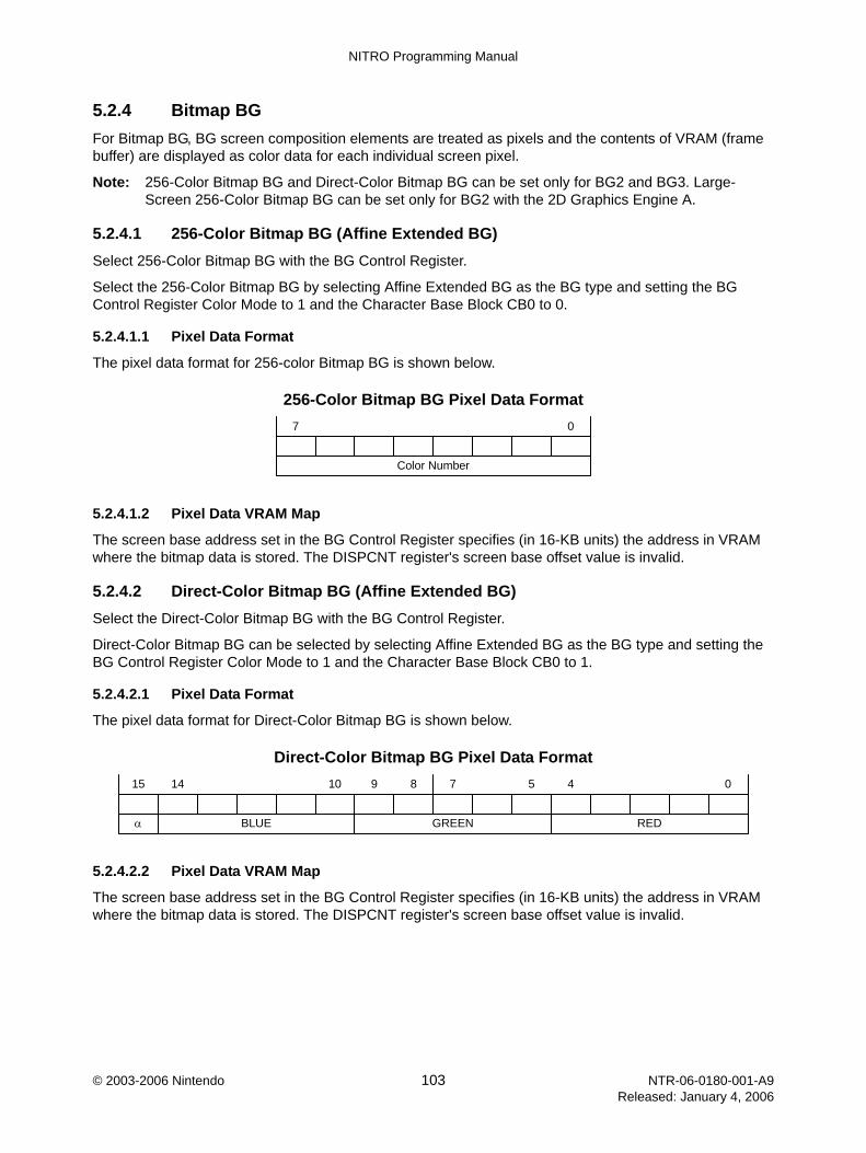
NITRO Programming Manual
5.2.4 Bitmap BGFor Bitmap BG, BG screen composition elements are treated as pixels and the contents of VRAM (frame buffer) are displayed as color data for each individual screen pixel.
Note: 256-Color Bitmap BG and Direct-Color Bitmap BG can be set only for BG2 and BG3. Large-Screen 256-Color Bitmap BG can be set only for BG2 with the 2D Graphics Engine A.
5.2.4.1 256-Color Bitmap BG (Affine Extended BG)Select 256-Color Bitmap BG with the BG Control Register.
Select the 256-Color Bitmap BG by selecting Affine Extended BG as the BG type and setting the BG Control Register Color Mode to 1 and the Character Base Block CB0 to 0.
5.2.4.1.1 Pixel Data Format
The pixel data format for 256-color Bitmap BG is shown below.
256-Color Bitmap BG Pixel Data Format
5.2.4.1.2 Pixel Data VRAM Map
The screen base address set in the BG Control Register specifies (in 16-KB units) the address in VRAM where the bitmap data is stored. The DISPCNT register's screen base offset value is invalid.
5.2.4.2 Direct-Color Bitmap BG (Affine Extended BG)Select the Direct-Color Bitmap BG with the BG Control Register.
Direct-Color Bitmap BG can be selected by selecting Affine Extended BG as the BG type and setting the BG Control Register Color Mode to 1 and the Character Base Block CB0 to 1.
5.2.4.2.1 Pixel Data Format
The pixel data format for Direct-Color Bitmap BG is shown below.
Direct-Color Bitmap BG Pixel Data Format
5.2.4.2.2 Pixel Data VRAM Map
The screen base address set in the BG Control Register specifies (in 16-KB units) the address in VRAM where the bitmap data is stored. The DISPCNT register's screen base offset value is invalid.
Color Number
7 0
α BLUE GREEN RED
15 8 7 014 10 9 5 4
© 2003-2006 Nintendo 103 NTR-06-0180-001-A9Released: January 4, 2006

NITRO Programming Manual
5.2.4.3 Large-Screen 256-Color Bitmap BGThe Large-Screen 256-Color Bitmap BG cannot be used with 2D Graphics Engine B.
5.2.4.3.1 Pixel Data Format
The pixel data format for Large-Screen 256-Color Bitmap BG is shown below.
Large-Screen 256-Color Bitmap BG Pixel Data Format
5.2.4.3.2 Pixel Data VRAM Map
The starting address for pixel data is fixed to the starting address of BG-VRAM (0x6000000). Both the BG Control Register's screen base address and the DISPCNT Register's screen base offset value are invalid.
Color Number
7 0
NTR-06-0180-001-A9 104 © 2003-2006 NintendoReleased: January 4, 2006
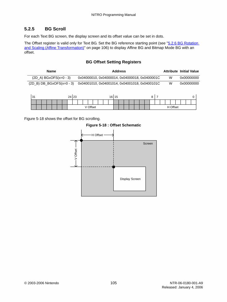
NITRO Programming Manual
5.2.5 BG ScrollFor each Text BG screen, the display screen and its offset value can be set in dots.
The Offset register is valid only for Text BG. Set the BG reference starting point (see "5.2.6 BG Rotation and Scaling (Affine Transformation)" on page 106) to display Affine BG and Bitmap Mode BG with an offset.
BG Offset Setting Registers
Figure 5-18 shows the offset for BG scrolling.
Figure 5-18 : Offset Schematic
Name Address Attribute Initial Value
(2D_A) BGxOFS(x=0 - 3) 0x04000010, 0x04000014, 0x04000018, 0x0400001C W 0x00000000
(2D_B) DB_BGxOFS(x=0 - 3) 0x04001010, 0x04001014, 0x04001018, 0x0400101C W 0x00000000
V Offset H Offset
31 24 23 16 15 8 7 0
Screen
H Offset
V O
ffset
Display Screen
© 2003-2006 Nintendo 105 NTR-06-0180-001-A9Released: January 4, 2006
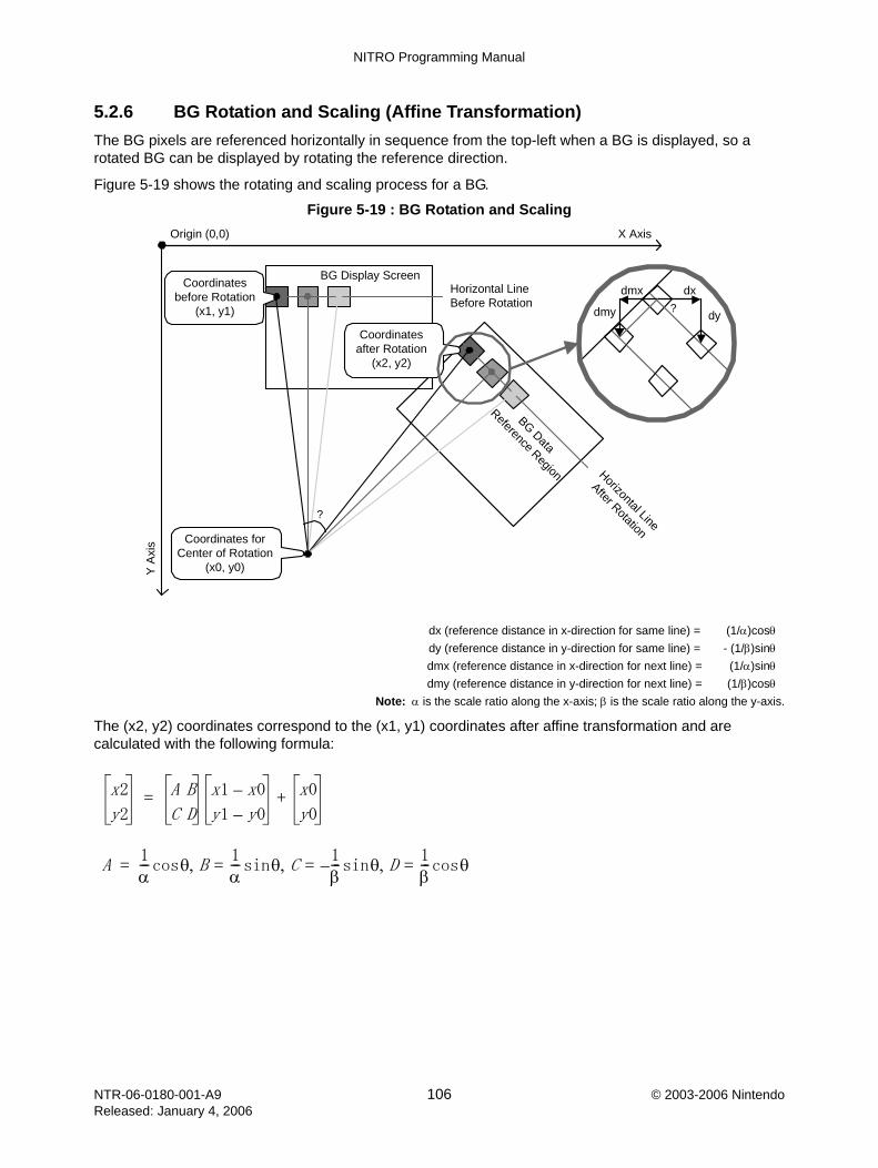
NITRO Programming Manual
5.2.6 BG Rotation and Scaling (Affine Transformation)The BG pixels are referenced horizontally in sequence from the top-left when a BG is displayed, so a rotated BG can be displayed by rotating the reference direction.
Figure 5-19 shows the rotating and scaling process for a BG.
Figure 5-19 : BG Rotation and Scaling
Note: α is the scale ratio along the x-axis; β is the scale ratio along the y-axis.
The (x2, y2) coordinates correspond to the (x1, y1) coordinates after affine transformation and are calculated with the following formula:
dx (reference distance in x-direction for same line) = (1/α)cosθdy (reference distance in y-direction for same line) = - (1/β)sinθdmx (reference distance in x-direction for next line) = (1/α)sinθdmy (reference distance in y-direction for next line) = (1/β)cosθ
Horizontal Line
After Rotation
BG Data
Reference Region
Horizontal Line Before Rotation
BG Display Screendx
dydmy
dmx
Origin (0,0) X Axis
Y A
xis
?
?
Coordinates before Rotation
(x1, y1)
Coordinates for Center of Rotation
(x0, y0)
Coordinates after Rotation
(x2, y2)
x2
y2
A B
C D
x1 x0–y1 y0–
x0
y0+=
A1α--- θcos B
1α--- θsin= C
1β--- θsin–= D
1β--- θcos=, , ,=
NTR-06-0180-001-A9 106 © 2003-2006 NintendoReleased: January 4, 2006
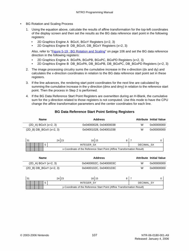
NITRO Programming Manual
• BG Rotation and Scaling Process
1. Using the equation above, calculate the results of affine transformation for the top-left coordinates of the display screen and then set the results as the BG data reference start point in the following registers:• 2D Graphics Engine A BGxX, BGxY Registers (x=2, 3)• 2D Graphics Engine B DB_BGxX, DB_BGxY Registers (x=2, 3)
Also, refer to "Figure 5-19 : BG Rotation and Scaling" on page 106 and set the BG data reference direction in the following registers:• 2D Graphics Engine A BGxPA, BGxPB, BGxPC, BGxPD Registers (x=2, 3)• 2D Graphics Engine B DB_BGxPA, DB_BGxPB, DB_BGxPC, DB_BGxPD Registers (x=2, 3)
2. The image processing circuitry sums the cumulative increase in the x-direction (dx and dy) and calculates the x-direction coordinates in relation to the BG data reference start point set in these registers.
3. If the line advances, the rendering start point coordinates for the next line are calculated by summing the cumulative increase in the y-direction (dmx and dmy) in relation to the reference start point. Then the process in Step 2 is performed.
4. If the BG Data Reference Start Point Registers are overwritten during an H-Blank, the cumulative sum for the y-direction related to those registers is not computed. Use this mode to have the CPU change the affine transformation parameters and the center coordinates for each line.
BG Data Reference Start Point Setting Registers
Name Address Attribute Initial Value
(2D_A) BGxX (x=2, 3) 0x04000028, 0x04000038 W 0x00000000
(2D_B) DB_BGxX (x=2, 3) 0x04001028, 0x04001038 W 0x00000000
Name Address Attribute Initial Value
(2D_A) BGxY (x=2, 3) 0x0400002C, 0x0400003C W 0x00000000
(2D_B) DB_BGxY (x=2, 3) 0x0400102C, 0x0400103C W 0x00000000
S INTEGER_SX DECIMAL_SX
x-Coordinate of the Reference Start Point (Affine Transformation Result)
31 24 23 16 15 8 7 0
S INTEGER_SY DECIMAL_SY
y-Coordinate of the Reference Start Point (Affine Transformation Result)
31 24 23 16 15 8 7 0
© 2003-2006 Nintendo 107 NTR-06-0180-001-A9Released: January 4, 2006
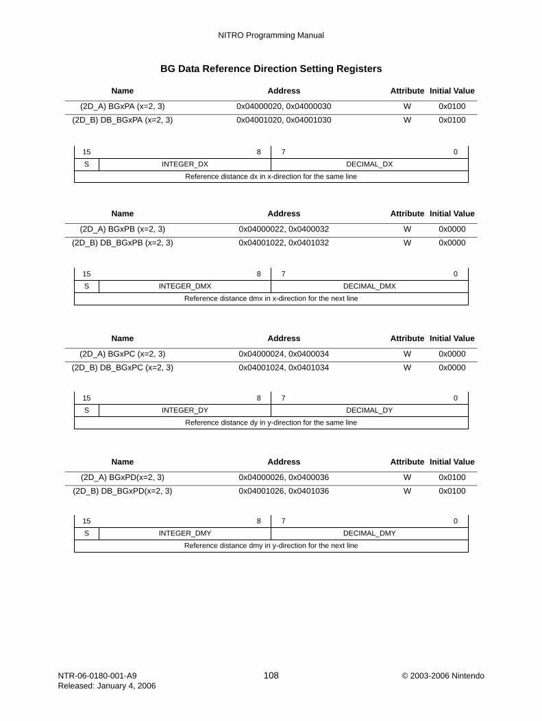
NITRO Programming Manual
BG Data Reference Direction Setting Registers
Name Address Attribute Initial Value
(2D_A) BGxPA (x=2, 3) 0x04000020, 0x04000030 W 0x0100
(2D_B) DB_BGxPA (x=2, 3) 0x04001020, 0x04001030 W 0x0100
Name Address Attribute Initial Value
(2D_A) BGxPB (x=2, 3) 0x04000022, 0x0400032 W 0x0000
(2D_B) DB_BGxPB (x=2, 3) 0x04001022, 0x0401032 W 0x0000
Name Address Attribute Initial Value
(2D_A) BGxPC (x=2, 3) 0x04000024, 0x0400034 W 0x0000
(2D_B) DB_BGxPC (x=2, 3) 0x04001024, 0x0401034 W 0x0000
Name Address Attribute Initial Value
(2D_A) BGxPD(x=2, 3) 0x04000026, 0x0400036 W 0x0100
(2D_B) DB_BGxPD(x=2, 3) 0x04001026, 0x0401036 W 0x0100
S INTEGER_DX DECIMAL_DX
Reference distance dx in x-direction for the same line
15 8 7 0
S INTEGER_DMX DECIMAL_DMX
Reference distance dmx in x-direction for the next line
15 8 7 0
S INTEGER_DY DECIMAL_DY
Reference distance dy in y-direction for the same line
15 8 7 0
S INTEGER_DMY DECIMAL_DMY
Reference distance dmy in y-direction for the next line
15 8 7 0
NTR-06-0180-001-A9 108 © 2003-2006 NintendoReleased: January 4, 2006

NITRO Programming Manual
5.3 OBJNITRO can handle two types of OBJ: Character OBJ and Bitmap OBJ. Table 5-7 summarizes the features for both Character OBJ and Bitmap OBJ.
Table 5-7 : OBJ Overview
Note: See "5.7 Color Special Effects" on page 146 to learn about OBJ color effects.
• Other items
See "5.6 Windows" on page 142 to learn about OBJ windows.
• Number of OBJ that can be displayed on one line
Table 5-7 gives the capacity of OBJ that can be displayed on one line under the most efficient conditions. When display OBJ are positioned in series from the start of OAM, the number of OBJ that can be displayed on one line is calculated as follows:
(H dot count x 6 – 6)/rendering cycle count) = Number of OBJ displayable on 1 line (128 max.)
H dot count is normally 355 dots, but it becomes 256 dots if the DISPCNT [DB_DISPCNT] Register’s OBJ Processing during H-Blank Period flag is set to 1 (see "4.2 LCD" on page 49).
x 6 represents the number of cycles that the OBJ rendering circuitry can use per dot. - 6 represents the number of cycles needed for the OBJ rendering pre-process at the start of the H-line.
Table 5-8 shows the relation between rendering cycle count and the number of OBJ that can be displayed on one line.
Item Character OBJ Bitmap OBJ
Number of Display Colors
1. Standard Palette 16 colors x 16 palettes 256 colors x 1 palette
2. Extended Palette 16 colors x 16 palettes (Standard Palette)
256 colors x 16 palettes (Extended Palette)
32,768 colors
Number of Characters(Converted to 8x8-Dot)
1. One-dimensional Mapping 1,024 to 8,192 (16-color mode) 512 to 4,096 (256-color mode)
2. Two-dimensional Mapping 1,024 (16-color mode) 512 (256-color mode)
1. 1D Mapping 1,024 to 2,048
2. 2D Mapping 256
Character Size 8x8 dot to 64x64 dot (12 varieties)
Maximum Number Displayed on One Screen 128 (converted to 64x64 dot)
Maximum Number Displayed on One Line 128 (converted to 8x8 dot)
Features HV Offset, HV Flip, Affine Transformation, Translucence (see note), Mosaic, and Priority settings
© 2003-2006 Nintendo 109 NTR-06-0180-001-A9Released: January 4, 2006
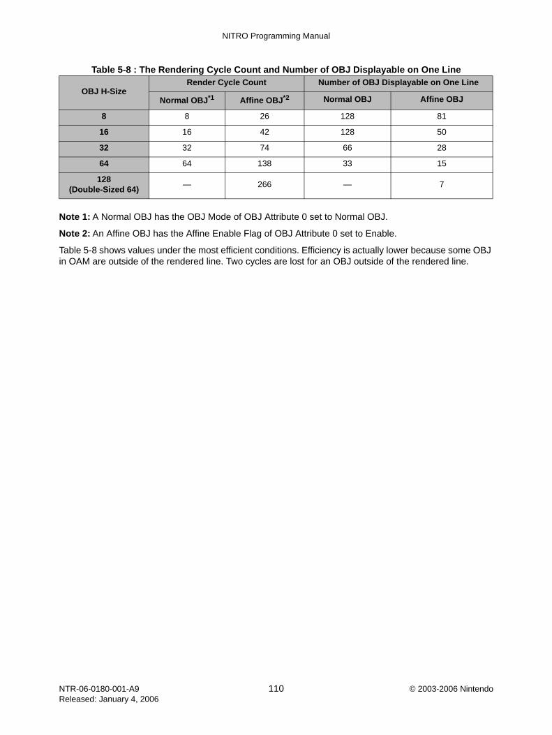
NITRO Programming Manual
Table 5-8 : The Rendering Cycle Count and Number of OBJ Displayable on One Line
Note 1: A Normal OBJ has the OBJ Mode of OBJ Attribute 0 set to Normal OBJ.
Note 2: An Affine OBJ has the Affine Enable Flag of OBJ Attribute 0 set to Enable.
Table 5-8 shows values under the most efficient conditions. Efficiency is actually lower because some OBJ in OAM are outside of the rendered line. Two cycles are lost for an OBJ outside of the rendered line.
OBJ H-SizeRender Cycle Count Number of OBJ Displayable on One Line
Normal OBJ*1 Affine OBJ*2 Normal OBJ Affine OBJ
8 8 26 128 81
16 16 42 128 50
32 32 74 66 28
64 64 138 33 15
128 (Double-Sized 64) — 266 — 7
NTR-06-0180-001-A9 110 © 2003-2006 NintendoReleased: January 4, 2006
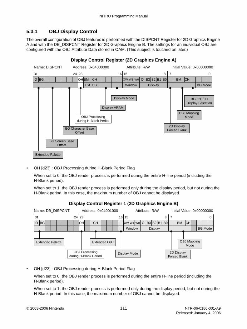
NITRO Programming Manual
5.3.1 OBJ Display ControlThe overall configuration of OBJ features is performed with the DISPCNT Register for 2D Graphics Engine A and with the DB_DISPCNT Register for 2D Graphics Engine B. The settings for an individual OBJ are configured with the OBJ Attribute Data stored in OAM. (This subject is touched on later.)
Display Control Register (2D Graphics Engine A)Name: DISPCNT Address: 0x04000000 Attribute: R/W Initial Value: 0x00000000
• OH [d23] : OBJ Processing during H-Blank Period Flag
When set to 0, the OBJ render process is performed during the entire H-line period (including the H-Blank period).
When set to 1, the OBJ render process is performed only during the display period, but not during the H-Blank period. In this case, the maximum number of OBJ cannot be displayed.
Display Control Register 1 (2D Graphics Engine B)Name: DB_DISPCNT Address: 0x04001000 Attribute: R/W Initial Value: 0x00000000
• OH [d23] : OBJ Processing during H-Blank Period Flag
When set to 0, the OBJ render process is performed during the entire H-line period (including the H-Blank period).
When set to 1, the OBJ render process is performed only during the display period, but not during the H-Blank period. In this case, the maximum number of OBJ cannot be displayed.
O BG OH BM CH OW W1 W0 O B3 B2 B1 B0 BM CH
Ext. OBJ Window Display BG Mode
31 24 23 16 15 8 7 0
Extended Palette
BG Screen Base Offset
BG Character Base Offset
OBJ Processing during H-Blank Period
Display VRAM
Display Mode
2D Display Forced Blank
OBJ Mapping Mode
BG0 2D/3D Display Selection
O BG OH CH OW W1 W0 O B3 B2 B1 B0 BM CH
Window Display BG Mode
31 24 23 16 15 8 7 0
Extended Palette
OBJ Processing during H-Blank Period
Display Mode 2D Display Forced Blank
OBJ Mapping Mode
Extended OBJ
© 2003-2006 Nintendo 111 NTR-06-0180-001-A9Released: January 4, 2006

NITRO Programming Manual
5.3.2 OAMAn OBJ is displayed by storing data in Object Attribute Memory (OAM). A total of 128 sets of OBJ data can be written to the NITRO Processor's internal OAM (1 KB from 07000000h – 070003FFh for 2D Graphics Engine A and 1 KB from 07000400h – 070007FFh for 2D Graphics Engine B). Accordingly, a total of 128 OBJ characters of any size can be displayed on the LCD.
5.3.2.1 Memory Map48 bits x 128 sets of OBJ Attribute data can be written to OAM. If an OBJ is to be rotated and scaled, then a total of 32 groups of affine transformation parameters PA, PB, PC, and PD can be written to OAM as shown in Figure 5-20.
Figure 5-20 : OAM Memory Map (add 0x400h to 2D Graphics Engine B Addresses)
Affine Transformation ParameterPD (31)
Attribute 2
Attribute 1
Attribute 0
Affine Transformation ParameterPB (0)
Attribute 2
Attribute 1
Attribute 0Affine Transformation Parameter
PA (0)Attribute 2
Attribute 1
Attribute 0
(16-bit Width)
0x070003FEh
0x070003F8h
0x07000008h
0x07000000h
OBJ 0
OBJ 1
OBJ 127
NTR-06-0180-001-A9 112 © 2003-2006 NintendoReleased: January 4, 2006
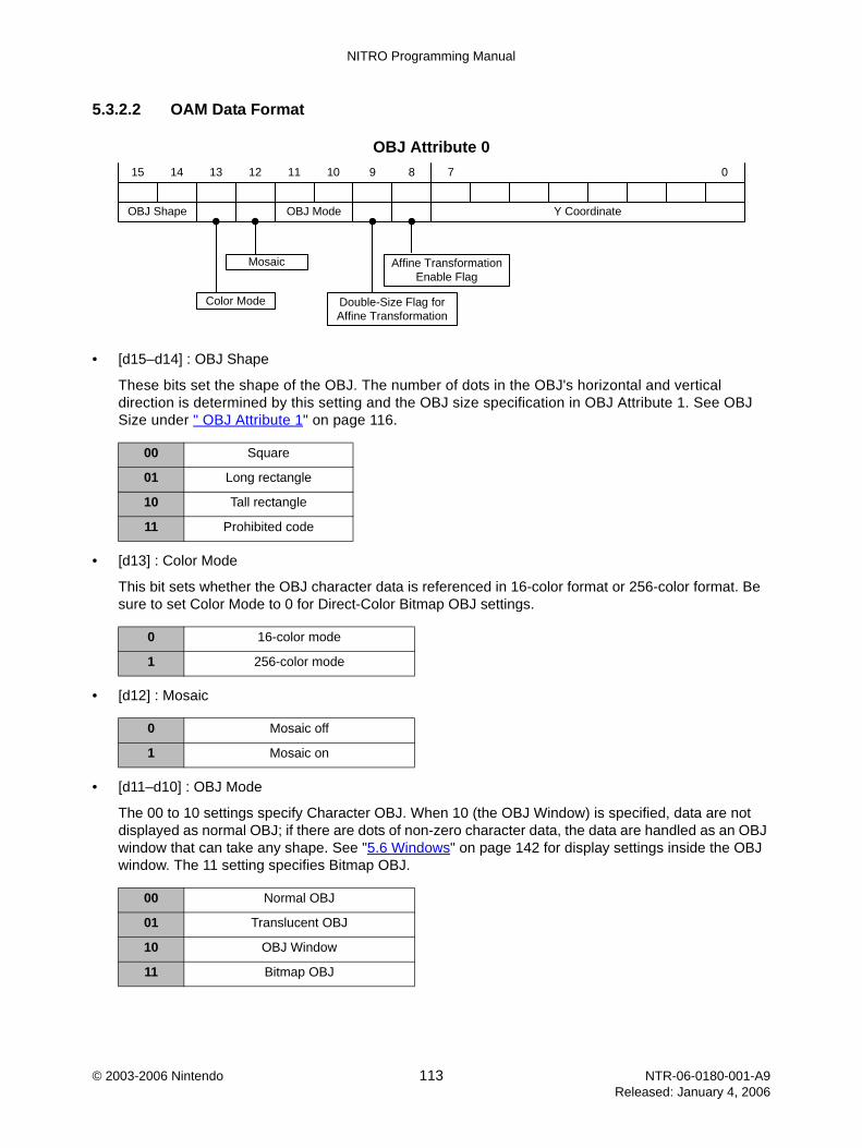
NITRO Programming Manual
5.3.2.2 OAM Data Format
OBJ Attribute 0
• [d15–d14] : OBJ Shape
These bits set the shape of the OBJ. The number of dots in the OBJ's horizontal and vertical direction is determined by this setting and the OBJ size specification in OBJ Attribute 1. See OBJ Size under " OBJ Attribute 1" on page 116.
• [d13] : Color Mode
This bit sets whether the OBJ character data is referenced in 16-color format or 256-color format. Be sure to set Color Mode to 0 for Direct-Color Bitmap OBJ settings.
• [d12] : Mosaic
• [d11–d10] : OBJ Mode
The 00 to 10 settings specify Character OBJ. When 10 (the OBJ Window) is specified, data are not displayed as normal OBJ; if there are dots of non-zero character data, the data are handled as an OBJ window that can take any shape. See "5.6 Windows" on page 142 for display settings inside the OBJ window. The 11 setting specifies Bitmap OBJ.
00 Square
01 Long rectangle
10 Tall rectangle
11 Prohibited code
0 16-color mode
1 256-color mode
0 Mosaic off
1 Mosaic on
00 Normal OBJ
01 Translucent OBJ
10 OBJ Window
11 Bitmap OBJ
OBJ Shape OBJ Mode Y Coordinate
15 8 7 0
Color Mode
Mosaic
Double-Size Flag for Affine Transformation
Affine Transformation Enable Flag
14 13 12 11 10 9
© 2003-2006 Nintendo 113 NTR-06-0180-001-A9Released: January 4, 2006

NITRO Programming Manual
• [d09] : Double-Size Flag for Affine Transformation
When the d08 Affine Transformation Enable Flag is set to 1, the OBJ field can be doubled in size for display. Using a double-size OBJ field allows a rotated OBJ to be displayed in its entirety without losing any sections. In addition, an OBJ can be enlarged up to double its original size and displayed without losing any sections (see Figure 5-21).
When the d08 Affine Transformation Enable Flag is set to 0 and this bit to 1, the OBJ is hidden.
Figure 5-21 : Affine Transformation of Double-Size OBJ Field
• [d08] : Affine Transformation Enable Flag
When this bit is enabled, the affine transformation parameters set in OBJ Attribute 1 are referenced.
When this bit is disabled and the d09 Double-Size Flag for Affine Transformation is set to 1, the OBJ is hidden.
• [d07–d00] : Y Coordinate
These bits specify the OBJ's Y coordinate in the display screen in the range of 0 to 255.
0 Disable double-size
1 Enable double-size
0 Disable
1 Enable
Normal Display Rotated Display
Enlarged Display usingDouble-Size OBJ Field
Rotated Display usingDouble-Size OBJ Field
NTR-06-0180-001-A9 114 © 2003-2006 NintendoReleased: January 4, 2006

NITRO Programming Manual
Workaround for AGB Problem with OBJ Wrapping
As shown in Figure 5-22, the AGB has a problem that prevents the upper part of the OBJ in the lower portion of the screen from displaying when the lower part of the OBJ was wrapped for display to the upper portion of the screen. This problem is corrected in NITRO (but the problem remains when NITRO is set to AGB-compatible mode).
Figure 5-22 : The Problem of OBJ Wrapping
Lower part of OBJ wrapped and displayed
Upper part of OBJ
LCD Display Region
Virtual Screen512 x 256
© 2003-2006 Nintendo 115 NTR-06-0180-001-A9Released: January 4, 2006

NITRO Programming Manual
OBJ Attribute 1
• [d15–d14] : OBJ Size
These bits set the OBJ size. The number of vertical and horizontal dots for an OBJ depends on this setting and the OBJ shape set in OBJ Attribute 0. Table 5-9 shows the relationship.
Table 5-9 : OBJ Shape and OBJ Size Settings
• [d13–d09] : Affine Transformation Parameter Selection
These bits specify which of the 32 sets of OAM PA – PD affine transformation parameters to reference.
When the OBJ Attribute 0 Affine Transformation Enable Flag is set to 0 (disabled), the [d13] VF bit is treated as the Vertical Flip Flag and the [d12] HF bit is treated as the Horizontal Flip Flag.
• [d08–d00] : x Coordinate
These bits specify the OBJ's x-coordinate in the display screen in the range of 0 to 511.
OBJ Attribute 1OBJ size
OBJ Attribute 0OBJ shape
00 01 10 11
00 (Square) 8x8 16x16 32x32 64x64
01 (Long rectangle) 16x8 32x8 32x16 64x32
10 (Tall rectangle) 8x16 8x32 16x32 32x64
11 (Prohibited setting) Prohibited Setting
VF HF
OBJ Size X Coordinate
15 14 13 12 9 8 7 0
Affine Transformation Parameter Selection
NTR-06-0180-001-A9 116 © 2003-2006 NintendoReleased: January 4, 2006

NITRO Programming Manual
OBJ Attribute 2
• [d15–d12] : Color Parameter
What these bits specify depends on whether OBJ Mode in OBJ Attribute 0 is set to Character OBJ or Bitmap OBJ. These bits specify the Color Palette Number for Character OBJ. They specify the αOAM for Bitmap OBJ. The αOAM value is used as a factor for blending with the BG for the Bitmap OBJ (see "5.3.4 Bitmap OBJ" on page 128).
1. For Character OBJ: Color Palette Number
This specifies one of 16 palettes to apply to the character data.
This bit is invalid in 256-color mode when extended palettes are disabled (see " OBJ Attribute 0" on page 113).
Extended palettes are enabled/disabled with the DISPCNT [DB_DISPCNT] register.
2. For Bitmap OBJ: αOAM value
The αOAM value is an element of the OBJ's transparency α, where α = αBMP x (αOAM +1). Set αBMP using the Bitmap OBJ data (see "5.3.4.1 Bitmap OBJ Data" on page 130).
• [d11–d10] : Display Priority
These bits set the order of priority for display.
See "5.9 Display Priority" on page 151 to learn about the priority relation with BG.
The priority set with this bit is invalid when OBJ Mode in OAM Attribute 0 is set to OBJ Window. See "5.6 Windows" on page 142 to learn about the precedence of windows.
• [d09–d00] : Starting Character Name
The basic character number at the start of the OBJ character data mapped in OBJ-VRAM is written here. The specification in Bitmap OBJ mode is the same as for Character mode with 8x8-dot units.
2D Mapping Mode
When in 2D Mapping mode and 256-Color mode, the starting character name's lowest bit is fixed at 0. In addition, OBJ-VRAM references regions only up to 32 KB.
1D Mapping Mode
When in 1D Mapping mode, the capacity of OBJ-VRAM can be expanded (see the RAM Bank Control Registers 0 and 1 and the Display Control Register).
Color Parameter Display Priority Starting Character Name
15 8 7 0
For Character OBJ: Color Palette NumberFor Bitmap OBJ: Valueα OAM
© 2003-2006 Nintendo 117 NTR-06-0180-001-A9Released: January 4, 2006
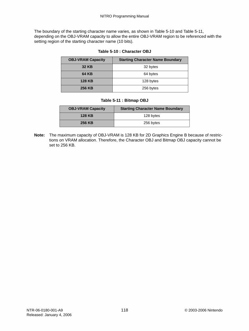
NITRO Programming Manual
The boundary of the starting character name varies, as shown in Table 5-10 and Table 5-11, depending on the OBJ-VRAM capacity to allow the entire OBJ-VRAM region to be referenced with the setting region of the starting character name (10 bits).
Table 5-10 : Character OBJ
Table 5-11 : Bitmap OBJ
Note: The maximum capacity of OBJ-VRAM is 128 KB for 2D Graphics Engine B because of restric-tions on VRAM allocation. Therefore, the Character OBJ and Bitmap OBJ capacity cannot be set to 256 KB.
OBJ-VRAM Capacity Starting Character Name Boundary
32 KB 32 bytes
64 KB 64 bytes
128 KB 128 bytes
256 KB 256 bytes
OBJ-VRAM Capacity Starting Character Name Boundary
128 KB 128 bytes
256 KB 256 bytes
NTR-06-0180-001-A9 118 © 2003-2006 NintendoReleased: January 4, 2006
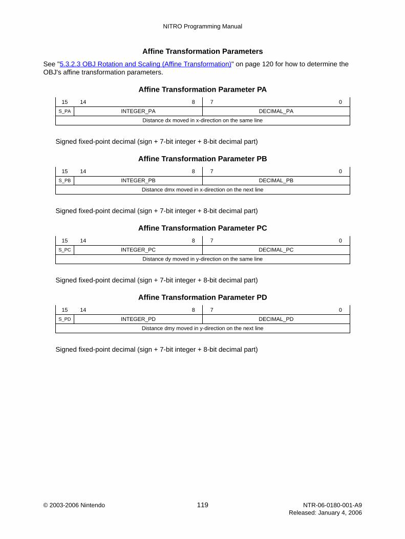
NITRO Programming Manual
Affine Transformation ParametersSee "5.3.2.3 OBJ Rotation and Scaling (Affine Transformation)" on page 120 for how to determine the OBJ's affine transformation parameters.
Affine Transformation Parameter PA
Signed fixed-point decimal (sign + 7-bit integer + 8-bit decimal part)
Affine Transformation Parameter PB
Signed fixed-point decimal (sign + 7-bit integer + 8-bit decimal part)
Affine Transformation Parameter PC
Signed fixed-point decimal (sign + 7-bit integer + 8-bit decimal part)
Affine Transformation Parameter PD
Signed fixed-point decimal (sign + 7-bit integer + 8-bit decimal part)
S_PA INTEGER_PA DECIMAL_PA
Distance dx moved in x-direction on the same line
15 8 7 014
S_PB INTEGER_PB DECIMAL_PB
Distance dmx moved in x-direction on the next line
15 8 7 014
S_PC INTEGER_PC DECIMAL_PC
Distance dy moved in y-direction on the same line
15 8 7 014
S_PD INTEGER_PD DECIMAL_PD
Distance dmy moved in y-direction on the next line
15 8 7 014
© 2003-2006 Nintendo 119 NTR-06-0180-001-A9Released: January 4, 2006
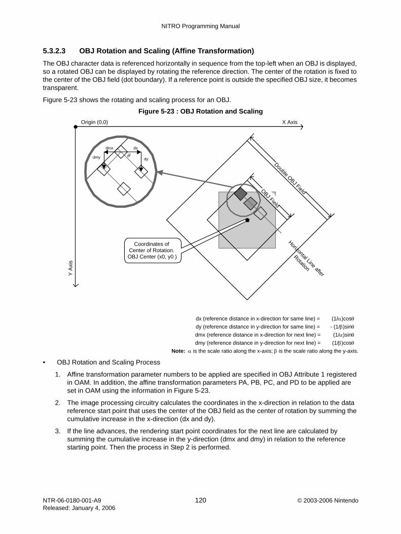
NITRO Programming Manual
5.3.2.3 OBJ Rotation and Scaling (Affine Transformation)The OBJ character data is referenced horizontally in sequence from the top-left when an OBJ is displayed, so a rotated OBJ can be displayed by rotating the reference direction. The center of the rotation is fixed to the center of the OBJ field (dot boundary). If a reference point is outside the specified OBJ size, it becomes transparent.
Figure 5-23 shows the rotating and scaling process for an OBJ.
Figure 5-23 : OBJ Rotation and Scaling
Note: α is the scale ratio along the x-axis; β is the scale ratio along the y-axis.
• OBJ Rotation and Scaling Process
1. Affine transformation parameter numbers to be applied are specified in OBJ Attribute 1 registered in OAM. In addition, the affine transformation parameters PA, PB, PC, and PD to be applied are set in OAM using the information in Figure 5-23.
2. The image processing circuitry calculates the coordinates in the x-direction in relation to the data reference start point that uses the center of the OBJ field as the center of rotation by summing the cumulative increase in the x-direction (dx and dy).
3. If the line advances, the rendering start point coordinates for the next line are calculated by summing the cumulative increase in the y-direction (dmx and dmy) in relation to the reference starting point. Then the process in Step 2 is performed.
dx (reference distance in x-direction for same line) = (1/α)cosθdy (reference distance in y-direction for same line) = - (1/β)sinθdmx (reference distance in x-direction for next line) = (1/α)sinθdmy (reference distance in y-direction for next line) = (1/β)cosθ
Coordinates ofCenter of Rotation.OBJ Center (x0, y0 )
Origin (0,0) X Axis
Y A
xis
Horizontal Line after
Rotation
OBJ FieldDouble OBJ Field
dx
dydmy
dmx
θ
NTR-06-0180-001-A9 120 © 2003-2006 NintendoReleased: January 4, 2006

NITRO Programming Manual
5.3.3 Character OBJFor OBJ character data, 8x8-dot sections are treated as basic characters and are assigned a Character Number. The OBJ size can be from 8x8 dots to 64x64 dots (12 different sizes). The OBJ character data base address is fixed as the VRAM base address. OBJ are defined as having either 16 colors or 256 colors, so the definition of a single basic character requires either 32 bytes or 64 bytes (both have the same format as BG character data).
The Color Mode setting in OAM OBJ Attribute 1 defines whether to reference OBJ character data in 16-Color format or 256-Color format. In addition, the palette specified in OBJ Attribute 2 is used when 16-Color mode has been set or when 256-Color mode is set when extended palettes are enabled. Extended palettes can be enabled/disabled with the DISPCNT [DB_DISPCNT] Register.
Select either 1D Mapping or 2D Mapping for character data VRAM mapping.
Display Control Register (2D Graphics Engine A)Name: DISPCNT Address: 0x04000000 Attribute: R/W Initial Value: 0x00000000
• [d22–d20] : OBJ-VRAM Region Extended Flag• CH [d21–d20] : VRAM Region Extended Flag for Character OBJ
These bits specify OBJ-VRAM capacity when OBJ character data uses 1D mapping. When set to 00, the capacity is the same as the AGB. Table 5-12 shows the starting character name boundaries that can be specified with OAM OBJ Attribute 2.
Table 5-12 : Starting Character Name Boundaries for OBJ Attribute 2
Note: When the OBJ-VRAM Region Setting flag has been set greater than the VRAM size allocated to the OBJ, do not access the region that exceeds the VRAM size allocated to the OBJ.
00 32 KB (Starting character name boundary: 32 bytes)
01 64 KB (Starting character name boundary: 64 bytes)
10 128 KB (Starting character name boundary: 128 bytes)
11 256 KB (Starting character name boundary: 256 bytes)
O BG OH BM CH OW W1 W0 O B3 B2 B1 B0 BM CH
Ext. OBJ Window Display BG Mode
31 24 23 16 15 8 7 0
Extended Palette
BG Screen Base Offset
BG Character Base Offset
OBJ Processing during H-Blank Period
Display VRAM
Display Mode
2D Display Forced Blank
OBJ Mapping Mode
BG0 2D/3D Display Selection
22 21 20 6 5 4
© 2003-2006 Nintendo 121 NTR-06-0180-001-A9Released: January 4, 2006
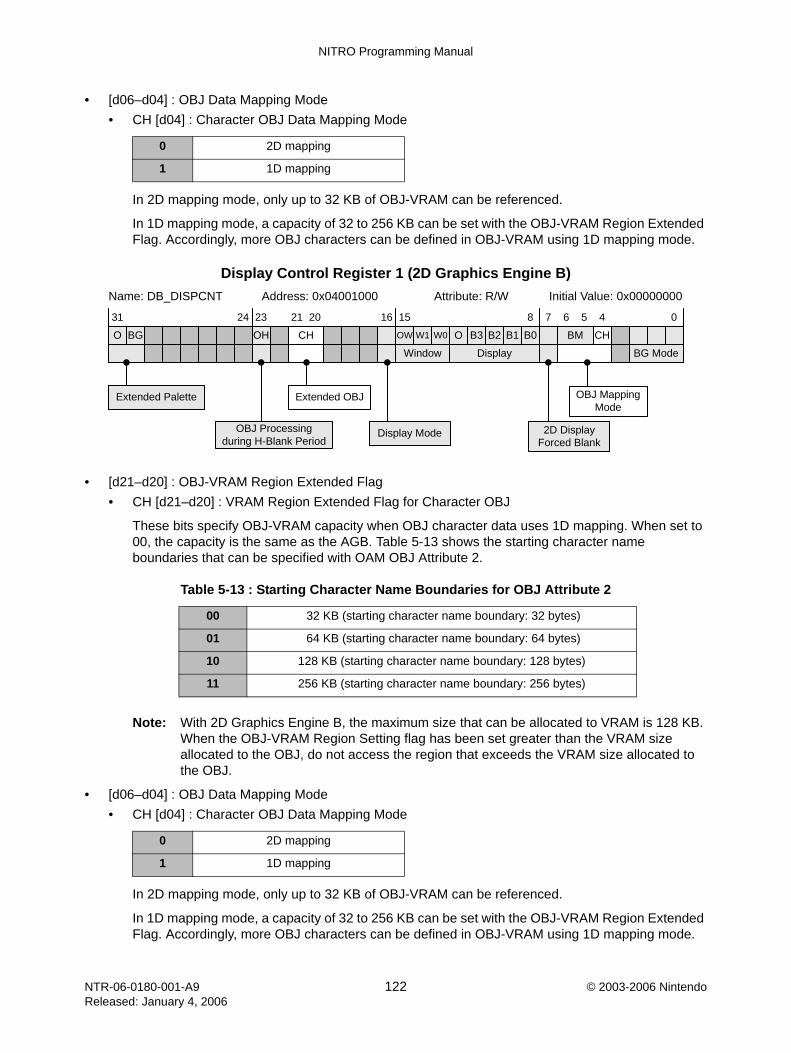
NITRO Programming Manual
• [d06–d04] : OBJ Data Mapping Mode• CH [d04] : Character OBJ Data Mapping Mode
In 2D mapping mode, only up to 32 KB of OBJ-VRAM can be referenced.
In 1D mapping mode, a capacity of 32 to 256 KB can be set with the OBJ-VRAM Region Extended Flag. Accordingly, more OBJ characters can be defined in OBJ-VRAM using 1D mapping mode.
Display Control Register 1 (2D Graphics Engine B)Name: DB_DISPCNT Address: 0x04001000 Attribute: R/W Initial Value: 0x00000000
• [d21–d20] : OBJ-VRAM Region Extended Flag• CH [d21–d20] : VRAM Region Extended Flag for Character OBJ
These bits specify OBJ-VRAM capacity when OBJ character data uses 1D mapping. When set to 00, the capacity is the same as the AGB. Table 5-13 shows the starting character name boundaries that can be specified with OAM OBJ Attribute 2.
Table 5-13 : Starting Character Name Boundaries for OBJ Attribute 2
Note: With 2D Graphics Engine B, the maximum size that can be allocated to VRAM is 128 KB. When the OBJ-VRAM Region Setting flag has been set greater than the VRAM size allocated to the OBJ, do not access the region that exceeds the VRAM size allocated to the OBJ.
• [d06–d04] : OBJ Data Mapping Mode• CH [d04] : Character OBJ Data Mapping Mode
In 2D mapping mode, only up to 32 KB of OBJ-VRAM can be referenced.
In 1D mapping mode, a capacity of 32 to 256 KB can be set with the OBJ-VRAM Region Extended Flag. Accordingly, more OBJ characters can be defined in OBJ-VRAM using 1D mapping mode.
0 2D mapping
1 1D mapping
00 32 KB (starting character name boundary: 32 bytes)
01 64 KB (starting character name boundary: 64 bytes)
10 128 KB (starting character name boundary: 128 bytes)
11 256 KB (starting character name boundary: 256 bytes)
0 2D mapping
1 1D mapping
O BG OH CH OW W1 W0 O B3 B2 B1 B0 BM CH
Window Display BG Mode
31 24 23 16 15 8 7 0
Extended Palette
OBJ Processing during H-Blank Period
Display Mode 2D Display Forced Blank
OBJ Mapping Mode
Extended OBJ
21 20 6 5 4
NTR-06-0180-001-A9 122 © 2003-2006 NintendoReleased: January 4, 2006
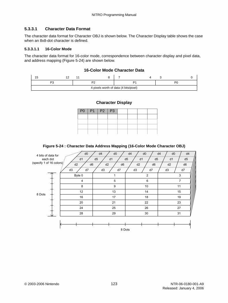
NITRO Programming Manual
5.3.3.1 Character Data FormatThe character data format for Character OBJ is shown below. The Character Display table shows the case when an 8x8-dot character is defined.
5.3.3.1.1 16-Color Mode
The character data format for 16-color mode, correspondence between character display and pixel data, and address mapping (Figure 5-24) are shown below.
16-Color Mode Character Data
Character Display
Figure 5-24 : Character Data Address Mapping (16-Color Mode Character OBJ)
P0 P1 P2 P3
P3 P2 P1 P0
4 pixels worth of data (4 bits/pixel)
15 12 11 8 7 4 3 0
4 bits of data for each dot
(specify 1 of 16 colors)
d4
d5
d6
d7
d0
d1
d2
d3
d4
d5
d6
d7
d0
d1
d2
d3
d4
d5
d6
d7
d0
d1
d2
d3
d4
d5
d6
d7
d0
d1
d2
d3
Byte 0
4
8
28
20
16
12
24
1
5
9
29
13
17
21
25
2
6
10
14
18
22
26
30
3
7
11
15
19
23
27
31
8 Dots
8 Dots
© 2003-2006 Nintendo 123 NTR-06-0180-001-A9Released: January 4, 2006
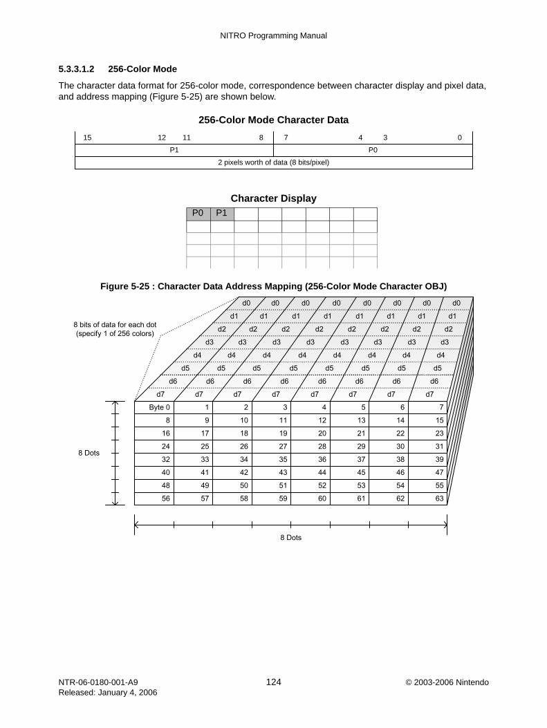
NITRO Programming Manual
5.3.3.1.2 256-Color Mode
The character data format for 256-color mode, correspondence between character display and pixel data, and address mapping (Figure 5-25) are shown below.
256-Color Mode Character Data
Character Display
Figure 5-25 : Character Data Address Mapping (256-Color Mode Character OBJ)
P0 P1
P1 P0
2 pixels worth of data (8 bits/pixel)
15 12 11 8 7 4 3 0
4
12
20
28
36
44
52
60
5
13
21
29
37
45
53
61
6
14
22
30
38
46
54
62
7
15
23
31
39
47
55
63
Byte 0
8
16
24
32
40
48
56
1
9
17
25
33
41
49
57
2
10
18
26
34
42
50
58
3
11
19
27
35
43
51
59
8 bits of data for each dot(specify 1 of 256 colors)
d0
d1
d4
d2
d3
d5
d6
d7
d0
d1
d4
d2
d3
d5
d6
d7
d0
d1
d4
d2
d3
d5
d6
d7
d0
d1
d4
d2
d3
d5
d6
d7
d0
d1
d4
d2
d3
d5
d6
d7
d0
d1
d4
d2
d3
d5
d6
d7
d0
d1
d4
d2
d3
d5
d6
d7
d0
d1
d4
d2
d3
d5
d6
d7
8 Dots
8 Dots
NTR-06-0180-001-A9 124 © 2003-2006 NintendoReleased: January 4, 2006
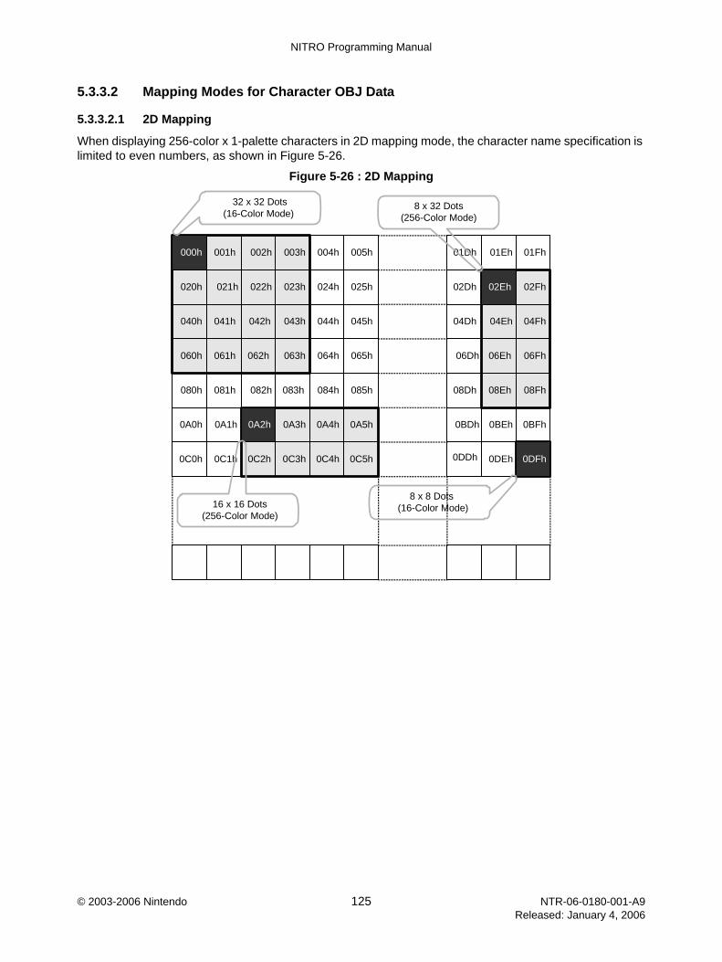
NITRO Programming Manual
5.3.3.2 Mapping Modes for Character OBJ Data
5.3.3.2.1 2D Mapping
When displaying 256-color x 1-palette characters in 2D mapping mode, the character name specification is limited to even numbers, as shown in Figure 5-26.
Figure 5-26 : 2D Mapping
000h 001h 002h 003h 004h 005h 01Dh 01Eh 01Fh
020h 021h 022h 023h 024h 025h
040h 041h 042h 043h 044h 045h
060h 061h 062h 063h 064h 065h
080h 081h 082h 083h 084h 085h
0A0h 0A2h0A1h 0A3h 0A4h 0A5h
0DFh
0BEh 0BFh
02Eh02Dh 02Fh
04Dh 04Eh 04Fh
06Dh 06Eh 06Fh
08Dh 08Eh 08Fh
0C0h 0C1h 0C2h 0C3h 0C4h 0C5h 0DDh 0DEh
0BDh
32 x 32 Dots(16-Color Mode)
8 x 8 Dots(16-Color Mode)
8 x 32 Dots(256-Color Mode)
16 x 16 Dots(256-Color Mode)
© 2003-2006 Nintendo 125 NTR-06-0180-001-A9Released: January 4, 2006
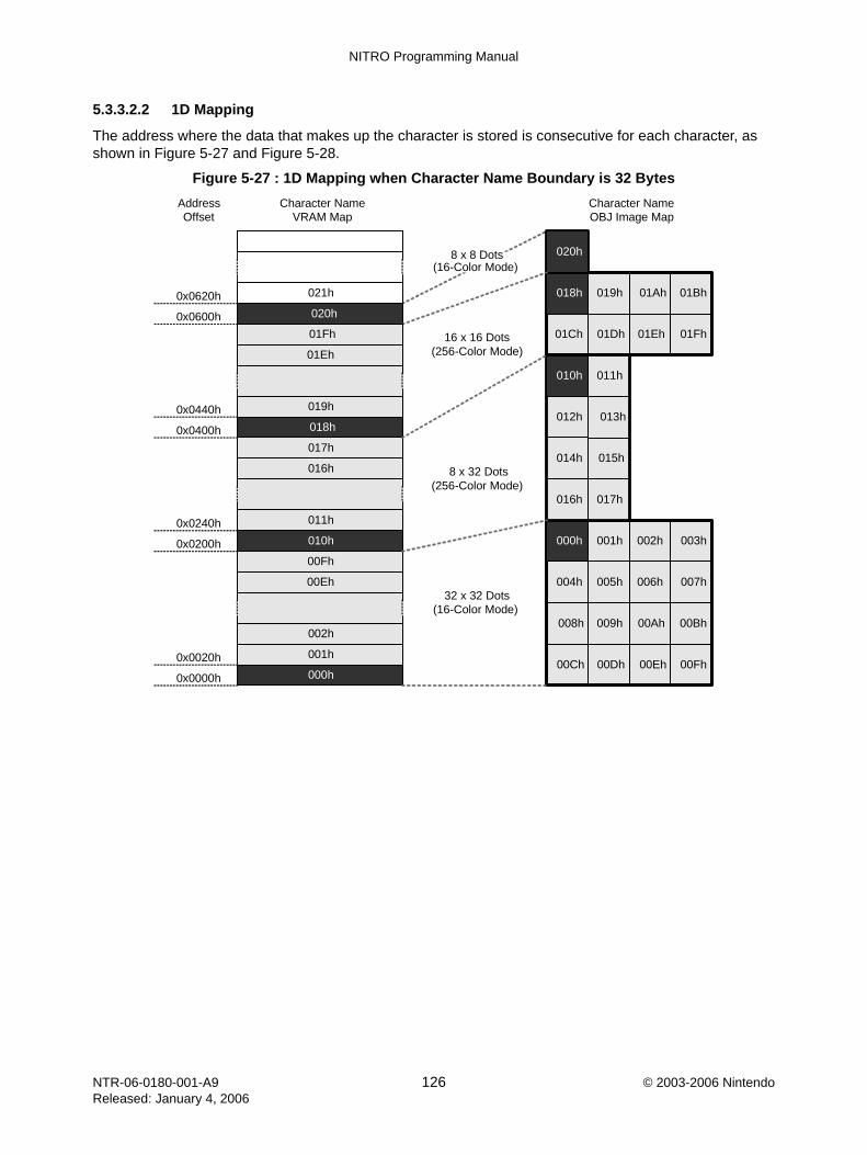
NITRO Programming Manual
5.3.3.2.2 1D Mapping
The address where the data that makes up the character is stored is consecutive for each character, as shown in Figure 5-27 and Figure 5-28.
Figure 5-27 : 1D Mapping when Character Name Boundary is 32 Bytes
8 x 8 Dots(16-Color Mode)
000h 001h 002h 003h
004h 005h 006h 007h
008h 009h 00Ah 00Bh
00Ch 00Dh 00Eh 00Fh
010h 011h
012h 013h
014h 015h
016h 017h
018h 019h 01Ah 01Bh
01Ch 01Dh 01Eh 01Fh
020h
00Fh
001h
000h
017h
010h
018h
020h
002h
00Eh
011h
019h
021h
01Fh
0x0000h
0x0200h
0x0400h
0x0600h
32 x 32 Dots(16-Color Mode)
8 x 32 Dots(256-Color Mode)
16 x 16 Dots(256-Color Mode)
0x0020h
0x0240h
0x0440h
0x0620h
016h
01Eh
AddressOffset
Character NameVRAM Map
Character NameOBJ Image Map
NTR-06-0180-001-A9 126 © 2003-2006 NintendoReleased: January 4, 2006

NITRO Programming Manual
Figure 5-28 : 1D Mapping when Character Name Boundary is 128 Bytes
000h
001h
002h
003h
004h
005h
006h
007h
008h
000h
004h
006h
008h
001h
0x 0000 h
0x 0200 h
0x 0300 h
0x 0400 h
0x 0080 h
005h
007h
AddressOffset
Character NameVRAM Map
32 x 32 Dots(16-Color Mode)
8 x 32 Dots(256-Color Mode)
16 x 16 Dots(256-Color Mode)
Character NameOBJ Image Map
8 x 8 Dots(16-Color Mode)
© 2003-2006 Nintendo 127 NTR-06-0180-001-A9Released: January 4, 2006
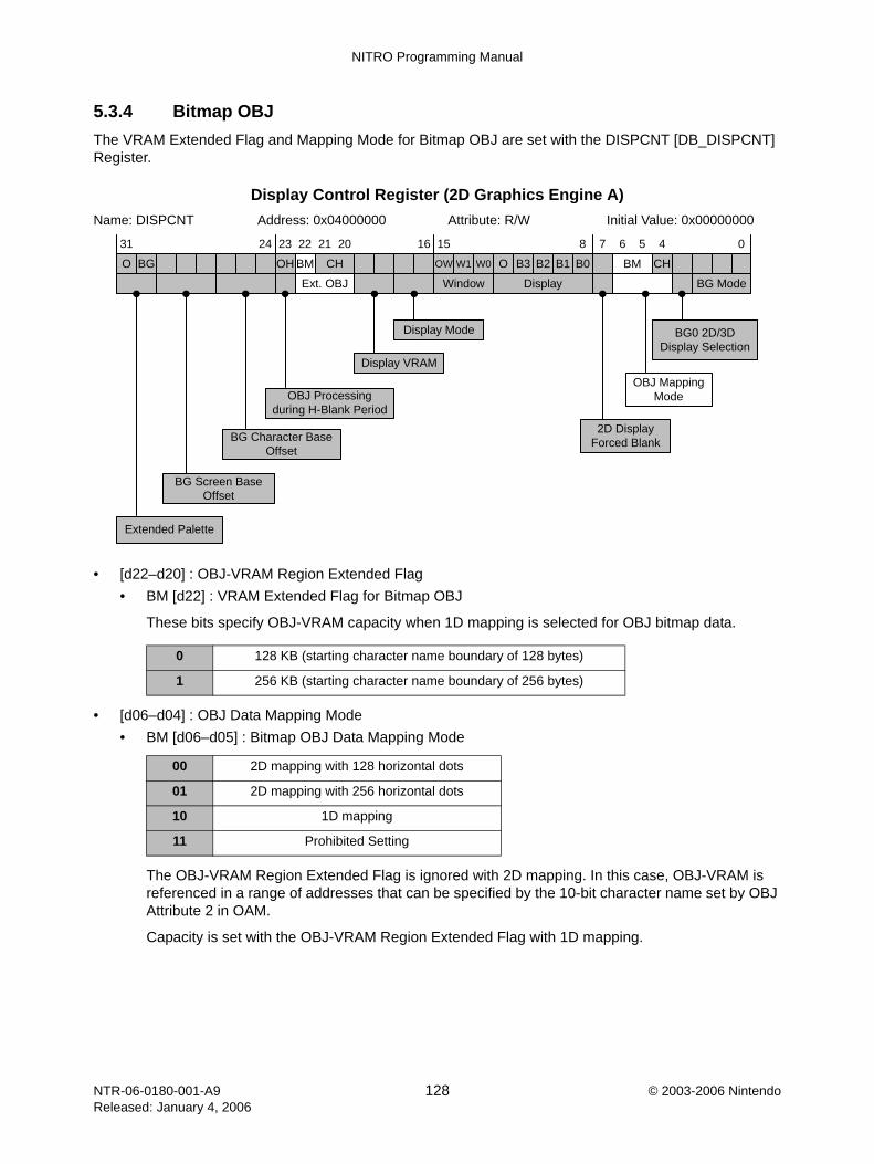
NITRO Programming Manual
5.3.4 Bitmap OBJThe VRAM Extended Flag and Mapping Mode for Bitmap OBJ are set with the DISPCNT [DB_DISPCNT] Register.
Display Control Register (2D Graphics Engine A)Name: DISPCNT Address: 0x04000000 Attribute: R/W Initial Value: 0x00000000
• [d22–d20] : OBJ-VRAM Region Extended Flag• BM [d22] : VRAM Extended Flag for Bitmap OBJ
These bits specify OBJ-VRAM capacity when 1D mapping is selected for OBJ bitmap data.
• [d06–d04] : OBJ Data Mapping Mode• BM [d06–d05] : Bitmap OBJ Data Mapping Mode
The OBJ-VRAM Region Extended Flag is ignored with 2D mapping. In this case, OBJ-VRAM is referenced in a range of addresses that can be specified by the 10-bit character name set by OBJ Attribute 2 in OAM.
Capacity is set with the OBJ-VRAM Region Extended Flag with 1D mapping.
0 128 KB (starting character name boundary of 128 bytes)
1 256 KB (starting character name boundary of 256 bytes)
00 2D mapping with 128 horizontal dots
01 2D mapping with 256 horizontal dots
10 1D mapping
11 Prohibited Setting
O BG OH BM CH OW W1 W0 O B3 B2 B1 B0 BM CH
Ext. OBJ Window Display BG Mode
31 24 23 16 15 8 7 0
Extended Palette
BG Screen Base Offset
BG Character Base Offset
OBJ Processing during H-Blank Period
Display VRAM
Display Mode
2D Display Forced Blank
OBJ Mapping Mode
BG0 2D/3D Display Selection
22 21 20 6 5 4
NTR-06-0180-001-A9 128 © 2003-2006 NintendoReleased: January 4, 2006

NITRO Programming Manual
DB_DISPCNT: Display Control Register 1 (2D Graphics Engine B)Name: DB_DISPCNT Address: 0x04001000 Attribute: R/W Initial Value: 0x00000000
• [d06–d04] : OBJ Data Mapping Mode• BM [d06–d05] : Bitmap OBJ Data Mapping Mode
In 2D mapping mode, only up to 32 KB of OBJ-VRAM can be referenced.
In 1D mapping mode, OBJ-VRAM capacity is set to 128 KB.
Note: With 2D Graphics Engine B, a maximum of 128 KB can be allocated to VRAM. Accordingly, although it can be specified for 2D Graphics Engine A, the OBJ-VRAM capacity for 1D mapping mode is fixed to 128 KB.
00 2D mapping with 128 horizontal dots
01 2D mapping with 256 horizontal dots
10 1D mapping
11 Prohibited Setting
O BG OH CH OW W1 W0 O B3 B2 B1 B0 BM CH
Window Display BG Mode
31 24 23 16 15 8 7 0
Extended Palette
OBJ Processing during H-Blank Period
Display Mode 2D Display Forced Blank
OBJ Mapping Mode
Extended OBJ
6 5 4
© 2003-2006 Nintendo 129 NTR-06-0180-001-A9Released: January 4, 2006
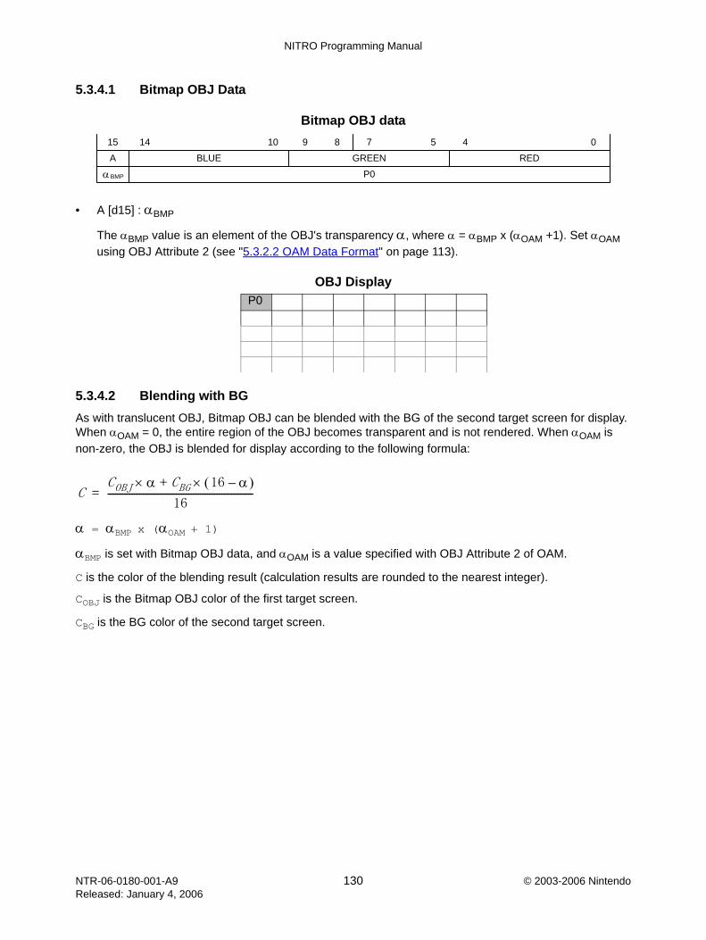
NITRO Programming Manual
5.3.4.1 Bitmap OBJ Data
Bitmap OBJ data
• A [d15] : αBMP
The αBMP value is an element of the OBJ's transparency α, where α = αBMP x (αOAM +1). Set αOAM using OBJ Attribute 2 (see "5.3.2.2 OAM Data Format" on page 113).
OBJ Display
5.3.4.2 Blending with BGAs with translucent OBJ, Bitmap OBJ can be blended with the BG of the second target screen for display. When αOAM = 0, the entire region of the OBJ becomes transparent and is not rendered. When αOAM is non-zero, the OBJ is blended for display according to the following formula:
α = αBMP x (αOAM + 1)
αBMP is set with Bitmap OBJ data, and αOAM is a value specified with OBJ Attribute 2 of OAM.
C is the color of the blending result (calculation results are rounded to the nearest integer).
COBJ is the Bitmap OBJ color of the first target screen.
CBG is the BG color of the second target screen.
P0
A BLUE GREEN RED
BMP P0
15 14 10 9 8 7 5 4 0
α
CCOBJ α CBG+× 16 α–( )×
16-------------------------------------------------------------=
NTR-06-0180-001-A9 130 © 2003-2006 NintendoReleased: January 4, 2006

NITRO Programming Manual
5.3.4.3 Mapping Modes for Bitmap OBJ Data
5.3.4.3.1 2D Mapping with 128 Horizontal Dots
Figure 5-29 shows the 2D map of Bitmap OBJ data with 128 horizontal dots in VRAM.
Figure 5-29 : 2D Map of Bitmap OBJ Data VRAM (128 Horizontal Dots)
Character names are set in units of 8x8 dots (128 bytes) of bitmap data. Figure 5-30 shows the 2D image map of character names in VRAM.
Figure 5-30 : 2D Image Map of Character Name VRAM
Dot 0 1 2 3 125 126 127
Line 0 0h 2h 4h 6h FAh FCh FEh
1 100h 102h 104h 106h 1FAh 1FCh 1FEh
2 200h 202h 2FCh 2FEh
3 300h 302h 3FCh 3FEh
4 400h 4FEh
0-7 8-15 16-23 24-31 104-111 112-119 120-127
0-7 0h 1h 2h 3h Dh Eh Fh
8-15 10h 11h 12h 13h 1Dh 1Eh 1Fh
16-23 20h 21h 22h 23h 2Dh 2Eh 2Fh
24-31 30h 31h 32h 33h 3Dh 3Eh 3Fh
32-39 40h 41h 42h 43h 4Dh 4Eh 4Fh
LineDot
© 2003-2006 Nintendo 131 NTR-06-0180-001-A9Released: January 4, 2006

NITRO Programming Manual
5.3.4.3.2 2D Mapping with 256 Horizontal Dots
Figure 5-31 shows the 2D map of Bitmap OBJ data with 256 horizontal dots in VRAM.
Figure 5-31 : 2D Map of Bitmap OBJ Data VRAM (256 Horizontal Dots)
Character names are set in units of 8x8 dots (128 bytes) of bitmap data. Figure 5-32 shows the 2D image map of character names in VRAM.
Figure 5-32 : 2D Image Map of Character Name VRAM
Dot 0 1 2 3 253 254 255
Line 0 0h 2h 4h 6h 1FAh 1FCh 1FEh
1 200h 202h 204h 206h 3FAh 3FCh 3FEh
2 400h 402h 5FCh 5FEh
3 600h 602h 7FCh 7FEh
4 800h 9FEh
Dot 0-7 8-15 16-23 24-31 232-239 240-247 248-255
0-7 0h 1h 2h 3h 1Dh 1Eh 1Fh
8-15 20h 21h 22h 23h 3Dh 3Eh 3Fh
16-23 40h 41h 42h 43h 5Dh 5Eh 5Fh
24-31 60h 61h 62h 63h 7Dh 7Eh 7Fh
32-39 80h 81h 82h 83h 9Dh 9Eh 9Fh
Line
NTR-06-0180-001-A9 132 © 2003-2006 NintendoReleased: January 4, 2006
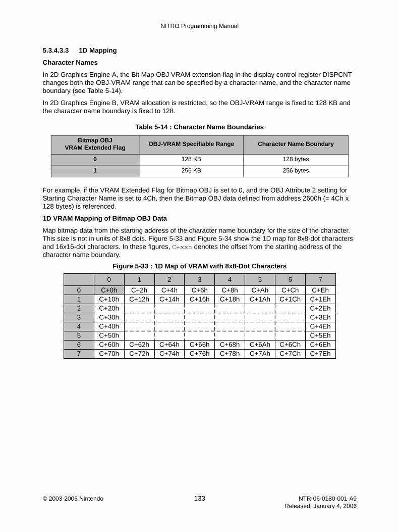
NITRO Programming Manual
5.3.4.3.3 1D Mapping
Character Names
In 2D Graphics Engine A, the Bit Map OBJ VRAM extension flag in the display control register DISPCNT changes both the OBJ-VRAM range that can be specified by a character name, and the character name boundary (see Table 5-14).
In 2D Graphics Engine B, VRAM allocation is restricted, so the OBJ-VRAM range is fixed to 128 KB and the character name boundary is fixed to 128.
Table 5-14 : Character Name Boundaries
For example, if the VRAM Extended Flag for Bitmap OBJ is set to 0, and the OBJ Attribute 2 setting for Starting Character Name is set to 4Ch, then the Bitmap OBJ data defined from address 2600h (= 4Ch x 128 bytes) is referenced.
1D VRAM Mapping of Bitmap OBJ Data
Map bitmap data from the starting address of the character name boundary for the size of the character. This size is not in units of 8x8 dots. Figure 5-33 and Figure 5-34 show the 1D map for 8x8-dot characters and 16x16-dot characters. In these figures, C+xxh denotes the offset from the starting address of the character name boundary.
Figure 5-33 : 1D Map of VRAM with 8x8-Dot Characters
Bitmap OBJ VRAM Extended Flag OBJ-VRAM Specifiable Range Character Name Boundary
0 128 KB 128 bytes
1 256 KB 256 bytes
0 1 2 5 6 70 C+0h C+2h C+4h C+Ah C+Ch C+Eh1 C+10h C+12h C+14h C+1Ah C+1Ch C+1Eh2 C+20h C+2Eh3
7 C+70h C+72h C+74h C+7Ah C+7Ch C+7Eh
5 C+50h C+5Eh6 C+60h C+62h C+64h C+6Ah C+6Ch C+6Eh
4
3 4C+6h C+8h
C+16h C+18h
C+76h C+78hC+66h C+68h
C+30hC+40h
C+3EhC+4Eh
© 2003-2006 Nintendo 133 NTR-06-0180-001-A9Released: January 4, 2006
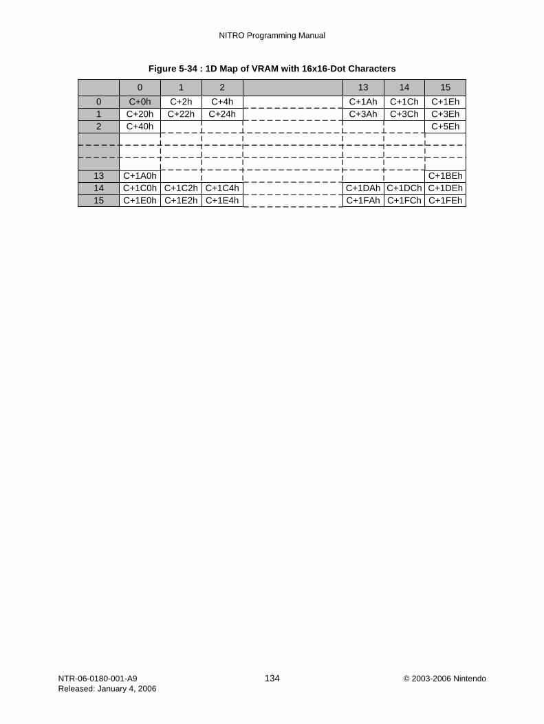
NITRO Programming Manual
Figure 5-34 : 1D Map of VRAM with 16x16-Dot Characters
0 1 2 13 14 150 C+0h C+2h C+4h C+1Ah C+1Ch C+1Eh1 C+20h C+22h C+24h C+3Ah C+3Ch C+3Eh2 C+40h C+5Eh
15 C+1E0h C+1E2h C+1E4h C+1FAh C+1FCh C+1FEh
13 C+1A0h C+1BEh14 C+1C0h C+1C2h C+1C4h C+1DAh C+1DCh C+1DEh
NTR-06-0180-001-A9 134 © 2003-2006 NintendoReleased: January 4, 2006
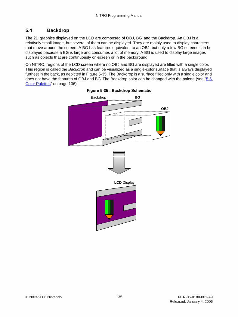
NITRO Programming Manual
5.4 BackdropThe 2D graphics displayed on the LCD are composed of OBJ, BG, and the Backdrop. An OBJ is a relatively small image, but several of them can be displayed. They are mainly used to display characters that move around the screen. A BG has features equivalent to an OBJ, but only a few BG screens can be displayed because a BG is large and consumes a lot of memory. A BG is used to display large images such as objects that are continuously on-screen or in the background.
On NITRO, regions of the LCD screen where no OBJ and BG are displayed are filled with a single color. This region is called the Backdrop and can be visualized as a single-color surface that is always displayed furthest in the back, as depicted in Figure 5-35. The Backdrop is a surface filled only with a single color and does not have the features of OBJ and BG. The Backdrop color can be changed with the palette (see "5.5 Color Palettes" on page 136).
Figure 5-35 : Backdrop Schematic
OBJ
BGBackdrop
LCD Display
© 2003-2006 Nintendo 135 NTR-06-0180-001-A9Released: January 4, 2006

NITRO Programming Manual
5.5 Color PalettesAs a standard feature, NITRO has RAM allocated specifically for BG and OBJ palettes (Palette RAM). Data stored in Palette RAM are called standard palettes.
A BG or OBJ can be displayed using just a standard palette, but extended palettes allow the use of 256 colors x 16 palettes and enable richer visuals. To use extended palettes, allocate VRAM using the RAM Control Register and enable the Extended Palette Flag with the DISPCNT [DB_DISPCNT] Register.
5.5.1 Standard PalettesStandard palette RAM is allocated separately for OBJ and for BG in both 2D Graphics Engine A and 2D Graphics Engine B. Color 0 in each palette is the transparent color, regardless of the settings. The Backdrop screen uses the color set at the beginning of the BG palette (Color 0 of Palette 0). Because standard palette RAM resides inside the 2D Graphic Engines, the 2D Graphic Engine must be enabled in the Power Control Register (POWCNT) before data can be written to its RAM.
Figure 5-36 shows the standard palette RAM addresses. Figure 5-37 shows the color specifications for 16 Colors x 16 Palettes. Figure 5-38 shows the color specifications for 256 Colors x 1 Palette.
Figure 5-36 : Standard Palette RAM Addresses (Add 0x400h for 2D Graphics Engine B)
Figure 5-37 : 16 Colors x 16 Palettes
Figure 5-38 : 256 Colors x 1 Palette
0x050003FFh
0x05000200h0x050001FFh
0x05000000h
OBJ Palette RAM(512 bytes)
BG Palette RAM(512 bytes)
Start of palettes
Palette 15
Palette 2Palette 1Palette 0
Color 15
Color 2Color 1Color 0
Start of palettes
Color 255
Color 2Color 1Color 0
Palette
NTR-06-0180-001-A9 136 © 2003-2006 NintendoReleased: January 4, 2006
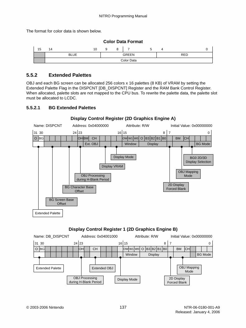
NITRO Programming Manual
The format for color data is shown below.
Color Data Format
5.5.2 Extended PalettesOBJ and each BG screen can be allocated 256 colors x 16 palettes (8 KB) of VRAM by setting the Extended Palette Flag in the DISPCNT [DB_DISPCNT] Register and the RAM Bank Control Register. When allocated, palette slots are not mapped to the CPU bus. To rewrite the palette data, the palette slot must be allocated to LCDC.
5.5.2.1 BG Extended Palettes
Display Control Register (2D Graphics Engine A)Name: DISPCNT Address: 0x04000000 Attribute: R/W Initial Value: 0x00000000
Display Control Register 1 (2D Graphics Engine B)Name: DB_DISPCNT Address: 0x04001000 Attribute: R/W Initial Value: 0x00000000
BLUE GREEN RED
Color Data
15 14 10 9 8 7 5 4 0
O BG OH BM CH OW W1 W0 O B3 B2 B1 B0 BM CH
Ext. OBJ Window Display BG Mode
31 24 23 16 15 8 7 0
Extended Palette
BG Screen Base Offset
BG Character Base Offset
OBJ Processing during H-Blank Period
Display VRAM
Display Mode
2D Display Forced Blank
OBJ Mapping Mode
BG0 2D/3D Display Selection
30
O BG OH CH OW W1 W0 O B3 B2 B1 B0 BM CH
Window Display BG Mode
31 24 23 16 15 8 7 0
Extended Palette
OBJ Processing during H-Blank Period
Display Mode 2D Display Forced Blank
OBJ Mapping Mode
Extended OBJ
30
© 2003-2006 Nintendo 137 NTR-06-0180-001-A9Released: January 4, 2006
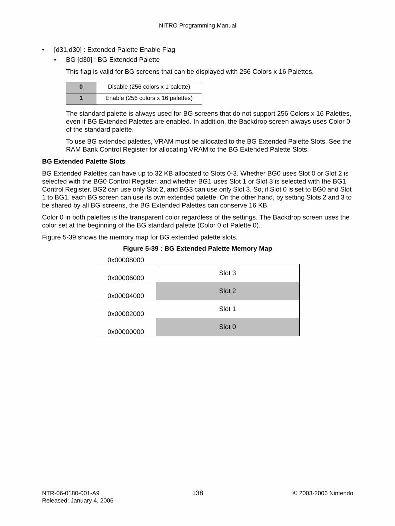
NITRO Programming Manual
• [d31,d30] : Extended Palette Enable Flag• BG [d30] : BG Extended Palette
This flag is valid for BG screens that can be displayed with 256 Colors x 16 Palettes.
The standard palette is always used for BG screens that do not support 256 Colors x 16 Palettes, even if BG Extended Palettes are enabled. In addition, the Backdrop screen always uses Color 0 of the standard palette.
To use BG extended palettes, VRAM must be allocated to the BG Extended Palette Slots. See the RAM Bank Control Register for allocating VRAM to the BG Extended Palette Slots.
BG Extended Palette Slots
BG Extended Palettes can have up to 32 KB allocated to Slots 0-3. Whether BG0 uses Slot 0 or Slot 2 is selected with the BG0 Control Register, and whether BG1 uses Slot 1 or Slot 3 is selected with the BG1 Control Register. BG2 can use only Slot 2, and BG3 can use only Slot 3. So, if Slot 0 is set to BG0 and Slot 1 to BG1, each BG screen can use its own extended palette. On the other hand, by setting Slots 2 and 3 to be shared by all BG screens, the BG Extended Palettes can conserve 16 KB.
Color 0 in both palettes is the transparent color regardless of the settings. The Backdrop screen uses the color set at the beginning of the BG standard palette (Color 0 of Palette 0).
Figure 5-39 shows the memory map for BG extended palette slots.
Figure 5-39 : BG Extended Palette Memory Map
0 Disable (256 colors x 1 palette)
1 Enable (256 colors x 16 palettes)
Slot 3
Slot 2
Slot 1
Slot 0
0x00008000
0x00006000
0x00004000
0x00002000
0x00000000
NTR-06-0180-001-A9 138 © 2003-2006 NintendoReleased: January 4, 2006

NITRO Programming Manual
Table 5-15 lists the palettes that can be used by each type of BG.
Table 5-15 : Palettes and BG Types
As shown in "Table 5-15 : Palettes and BG Types" on page 139, the Extended Palette Slot number can be selected for BG0 and for BG1. With 2D Graphics Engine B, Large-Screen 256-Color Bitmap BG cannot be selected for the BG type. See the section on the BG Control Register in "5.2.2 BG Control" on page 81 to learn how to select slots.
Category BG Type Colors/Palette
BG Screen
Usable Palette Region
StandardExtended Palette Slot
0 1 2 3
Character BG
Text BG
16/16 BG0–3 X
256/16
BG0 X X XBG1 X X XBG2 X XBG3 X X
Affine BG 256/1 BG2–3 X
Ext. BG
256-Color x 16- Palette BG 256/16
BG2 X XBG3 X X
BitmapBG
256-Color 256/1 BG2–3 X
Direct Color 32,768 BG2–3
Large-Screen 256-Color 256/1 BG2 X
© 2003-2006 Nintendo 139 NTR-06-0180-001-A9Released: January 4, 2006

NITRO Programming Manual
5.5.2.2 OBJ Extended Palettes
Display Control Register (2D Graphics Engine A)Name: DISPCNT Address: 0x04000000 Attribute: R/W Initial Value: 0x00000000
Display Control Register 1 (2D Graphics Engine B)Name: DB_DISPCNT Address: 0x04001000 Attribute: R/W Initial Value: 0x00000000
• [d31,d30] : Extended Palette Enable Flag• O [d31] : OBJ Extended Palette
The standard palette (palette RAM) is always used for 6-Color Mode OBJ, even if OBJ Extended Palettes are enabled. See "5.5 Color Palettes" on page 136 for more information on these palettes.
To use OBJ extended palettes, VRAM must be allocated to the OBJ Extended Palette Slots. See the RAM Bank Control Register for allocating VRAM to the OBJ Extended Palette Slots.
0 Disable (256 colors x 1 palette)
1 Enable (256 colors x 16 palettes)
O BG OH BM CH OW W1 W0 O B3 B2 B1 B0 BM CH
Ext. OBJ Window Display BG Mode
31 24 23 16 15 8 7 0
Extended Palette
BG Screen Base Offset
BG Character Base Offset
OBJ Processing during H-Blank Period
Display VRAM
Display Mode
2D Display Forced Blank
OBJ Mapping Mode
BG0 2D/3D Display Selection
30
O BG OH CH OW W1 W0 O B3 B2 B1 B0 BM CH
Window Display BG Mode
31 24 23 16 15 8 7 0
Extended Palette
OBJ Processing during H-Blank Period
Display Mode 2D Display Forced Blank
OBJ Mapping Mode
Extended OBJ
30
NTR-06-0180-001-A9 140 © 2003-2006 NintendoReleased: January 4, 2006

NITRO Programming Manual
OBJ Extended Palette Slots
Although 16 KB of VRAM is allocated to the OBJ extended palettes, only 8 KB of this can be used as an extended palette. As Figure 5-40 illustrates, only Slot 0 can be used as an extended palette; Slot 1 is invalid.
Color 0 for each palette is handled as the transparent color regardless of the settings. The Backdrop screen uses the color set at the beginning of the standard BG palette (Color 0 of Palette 0).
Figure 5-40 : OBJ Extended Palette Slot Memory Map
Slot 1 (Invalid Region)
Slot 0
0x00004000
0x00002000
0x00000000
© 2003-2006 Nintendo 141 NTR-06-0180-001-A9Released: January 4, 2006

NITRO Programming Manual
5.6 WindowsWindow features can restrict the regions where BG and OBJ screens are displayed as well as the region where color special effects are applied. NITRO uses three kinds of windows: Window 0, Window 1, and the OBJ Window (see OBJ Attribute 0 in "5.3 OBJ" on page 109 to read about the OBJ Window settings).
Window Interior Control Register
Window Exterior and OBJ Window Interior Control Register
• [d13], [d05] : EFCT: Color Special Effects Enable Flag
• OBJ, BG3-0 [d12–d08], [d04–d00] : Display Enable Flag
Display control over the window’s exterior is valid whenever Window 0, Window 1, or the OBJ Window is displayed.
Name Address Attribute Initial Value
(2D_A) WININ 0x04000048 R/W 0x0000
(2D_B) DB_WININ 0x04001048 R/W 0x0000
Name Address Attribute Initial Value
(2D_A) WINOUT 0x0400004A R/W 0x0000
(2D_B) DB_WINOUT 0x0400104A R/W 0x0000
0 Disable
1 Enable
0 Hide
1 Show
EFCT OBJ BG3 BG2 BG1 BG0 EFCT OBJ BG3 BG2 BG1 BG0
Inside Window 1 Inside Window 0
15 13 12 8 7 5 4 0
EFCT OBJ BG3 BG2 BG1 BG0 EFCT OBJ BG3 BG2 BG1 BG0
Inside OBJ Window Outside Window (0,1, and OBJ Windows)
15 13 12 8 7 5 4 0
NTR-06-0180-001-A9 142 © 2003-2006 NintendoReleased: January 4, 2006
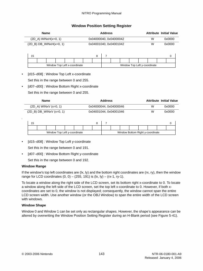
NITRO Programming Manual
Window Position Setting Register
• [d15–d08] : Window Top Left x-coordinate
Set this in the range between 0 and 255.
• [d07–d00] : Window Bottom Right x-coordinate
Set this in the range between 0 and 255.
(
• [d15–d08] : Window Top Left y-coordinate
Set this in the range between 0 and 191.
• [d07–d00] : Window Bottom Right y-coordinate
Set this in the range between 0 and 192.
Window Range
If the window's top left coordinates are (lx, ly) and the bottom right coordinates are (rx, ry), then the window range for LCD coordinates (0, 0) – (255, 191) is (lx, ly) – (rx-1, ry-1).
To locate a window along the right side of the LCD screen, set its bottom right x-coordinate to 0. To locate a window along the left side of the LCD screen, set the top left x-coordinate to 0. However, if both x-coordinates are set to 0, the window is not displayed; consequently, the window cannot span the entire LCD screen width. Use another window (or the OBJ Window) to span the entire width of the LCD screen with windows.
Window Shape
Window 0 and Window 1 can be set only as rectangular shapes. However, the shape’s appearance can be altered by overwriting the Window Position Setting Register during an H-Blank period (see Figure 5-41).
Name Address Attribute Initial Value
(2D_A) WINxH(x=0, 1) 0x04000040, 0x04000042 W 0x0000
(2D_B) DB_WINxH(x=0, 1) 0x04001040, 0x04001042 W 0x0000
Name Address Attribute Initial Value
(2D_A) WINxV (x=0, 1) 0x04000044, 0x04000046 W 0x0000
(2D_B) DB_WINxV (x=0, 1) 0x04001044, 0x04001046 W 0x0000
Window Top Left x-coordinate Window Top Left y-coordinate
15 8 7 0
Window Top Left y-coordinate Window Bottom Right y-coordinate
15 8 7 0
© 2003-2006 Nintendo 143 NTR-06-0180-001-A9Released: January 4, 2006
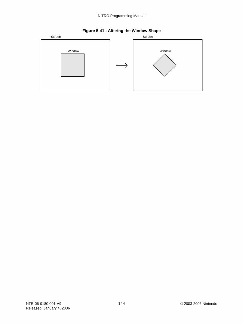
NITRO Programming Manual
Figure 5-41 : Altering the Window ShapeScreen Screen
Window Window
NTR-06-0180-001-A9 144 © 2003-2006 NintendoReleased: January 4, 2006

NITRO Programming Manual
5.6.1 The Precedence of WindowsAs shown in Figure 5-42, Window 0 always has display priority (precedence) over Window 1, and the OBJ Window has the lowest precedence. The precedence cannot be changed.
Figure 5-42 : The Display Priority of Window 0, Window 1, and the OBJ Window
Note 1 Regarding Windows: When the top left y-coordinate of the window is between 0 and 6, the top left y-coordinate is forcibly displayed as though it were 0. Use one of the following two methods to work around this problem.
Method 1: Perform the following steps:
1. Set the window's y-coordinate to a value of 7 or higher before the V-Count reaches 256 during the V-Blank process.
2. Restore the window's y-coordinate to its original value after confirming that V-Count has reached 262 by checking V-Count using a V-Count Match Interrupt or an H-Blank Interrupt.
Method 2: Perform the following steps:
1. Set the Window Display Enable Flag in the Display Control Register using the values shown below after confirming that V-Count has reached 262 by checking V-Count using a V-Count Match Interrupt or an H-Blank Interrupt.
When the window y-coordinate is 0: 1 (Show window)When the window y-coordinate is non-zero: 0 (Hide window)
2. Read the V-Count value using an H-Blank Interrupt and compare that value to (window y-coordinate – 1). If the two values are equal, set the Window Display Enable Flag in the Display Control Register to 1 (Show window) during the H-Blank.
Note 2 Regarding Windows: Immediately after drawing a line in which the bottom right x coordinate is set to 0, drawing of the current window will not be complete at H-Blank. If the coordinates of the next window are set in this state, the window will continue drawing up to the bottom right x coordinate of the next window.
To avoid this, you must wait until the window has finished drawing before setting the coordinates of the next window. If the bottom right x coordinate is 0, the window will finish drawing 3 clock cycles of the system clock (33MHz) after the H-Blank flag changes from 1 to 0 (or the V-Count value increments by 1). Between this point in time and the time when the H-Count reaches the top left x coordinate of the next window, it will be outside the window. So set the coordinates for the next window during this period. Note that you cannot use this method when setting window coordinates using H-Blank-initiated DMA.
OBJ Window
Window 1
Window 0
Screen
© 2003-2006 Nintendo 145 NTR-06-0180-001-A9Released: January 4, 2006
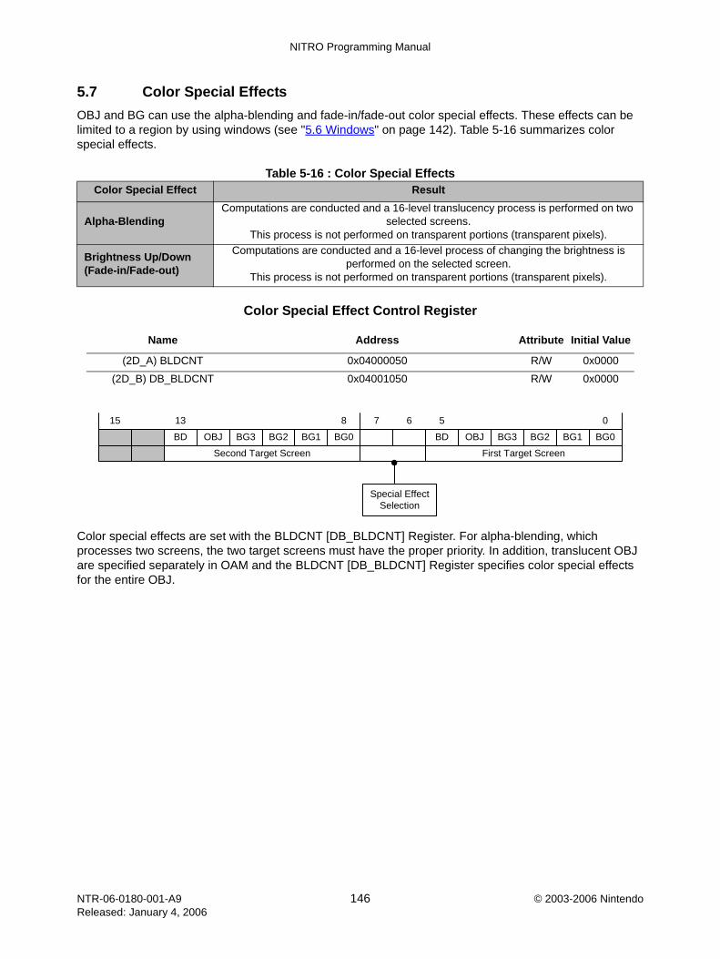
NITRO Programming Manual
5.7 Color Special EffectsOBJ and BG can use the alpha-blending and fade-in/fade-out color special effects. These effects can be limited to a region by using windows (see "5.6 Windows" on page 142). Table 5-16 summarizes color special effects.
Table 5-16 : Color Special Effects
Color Special Effect Control Register
Color special effects are set with the BLDCNT [DB_BLDCNT] Register. For alpha-blending, which processes two screens, the two target screens must have the proper priority. In addition, translucent OBJ are specified separately in OAM and the BLDCNT [DB_BLDCNT] Register specifies color special effects for the entire OBJ.
Color Special Effect Result
Alpha-BlendingComputations are conducted and a 16-level translucency process is performed on two
selected screens.This process is not performed on transparent portions (transparent pixels).
Brightness Up/Down(Fade-in/Fade-out)
Computations are conducted and a 16-level process of changing the brightness is performed on the selected screen.
This process is not performed on transparent portions (transparent pixels).
Name Address Attribute Initial Value
(2D_A) BLDCNT 0x04000050 R/W 0x0000
(2D_B) DB_BLDCNT 0x04001050 R/W 0x0000
BD OBJ BG3 BG2 BG1 BG0 BD OBJ BG3 BG2 BG1 BG0
Second Target Screen First Target Screen
15 13 8 7 6 5 0
Special Effect Selection
NTR-06-0180-001-A9 146 © 2003-2006 NintendoReleased: January 4, 2006
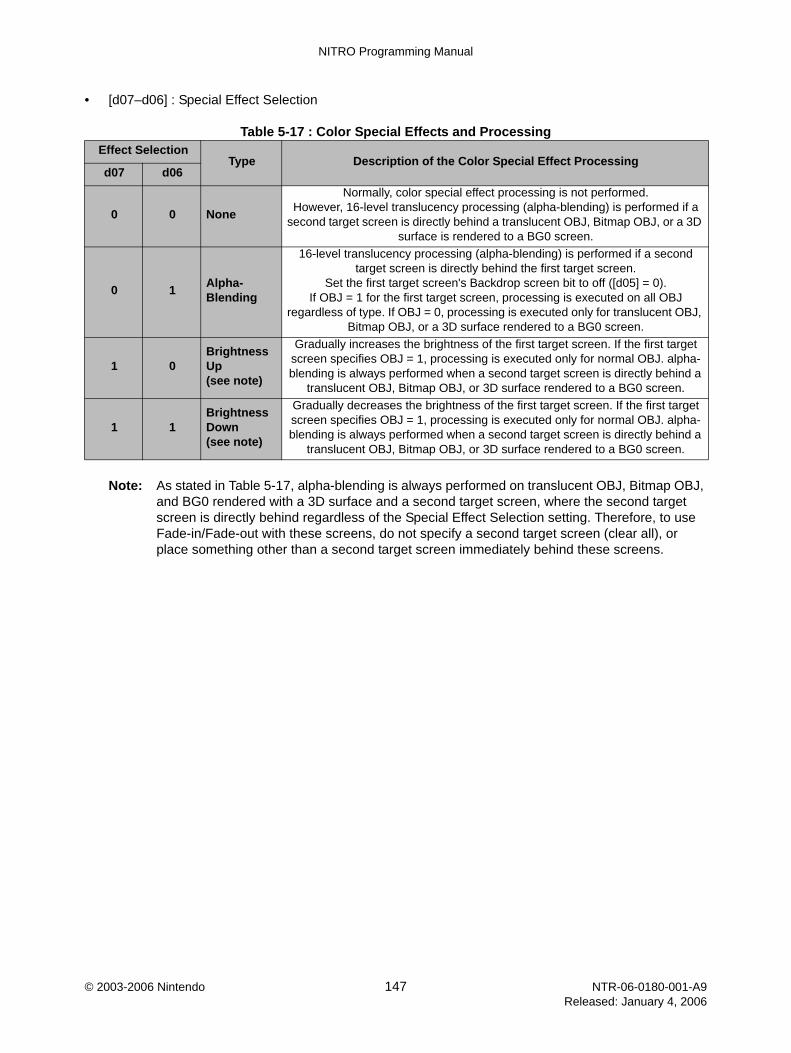
NITRO Programming Manual
• [d07–d06] : Special Effect Selection
Table 5-17 : Color Special Effects and Processing
Note: As stated in Table 5-17, alpha-blending is always performed on translucent OBJ, Bitmap OBJ, and BG0 rendered with a 3D surface and a second target screen, where the second target screen is directly behind regardless of the Special Effect Selection setting. Therefore, to use Fade-in/Fade-out with these screens, do not specify a second target screen (clear all), or place something other than a second target screen immediately behind these screens.
Effect SelectionType Description of the Color Special Effect Processing
d07 d06
0 0 None
Normally, color special effect processing is not performed.However, 16-level translucency processing (alpha-blending) is performed if a
second target screen is directly behind a translucent OBJ, Bitmap OBJ, or a 3D surface is rendered to a BG0 screen.
0 1 Alpha-Blending
16-level translucency processing (alpha-blending) is performed if a second target screen is directly behind the first target screen.
Set the first target screen's Backdrop screen bit to off ([d05] = 0).If OBJ = 1 for the first target screen, processing is executed on all OBJ
regardless of type. If OBJ = 0, processing is executed only for translucent OBJ, Bitmap OBJ, or a 3D surface rendered to a BG0 screen.
1 0Brightness Up(see note)
Gradually increases the brightness of the first target screen. If the first target screen specifies OBJ = 1, processing is executed only for normal OBJ. alpha-blending is always performed when a second target screen is directly behind a
translucent OBJ, Bitmap OBJ, or 3D surface rendered to a BG0 screen.
1 1Brightness Down(see note)
Gradually decreases the brightness of the first target screen. If the first target screen specifies OBJ = 1, processing is executed only for normal OBJ. alpha-blending is always performed when a second target screen is directly behind a
translucent OBJ, Bitmap OBJ, or 3D surface rendered to a BG0 screen.
© 2003-2006 Nintendo 147 NTR-06-0180-001-A9Released: January 4, 2006

NITRO Programming Manual
1. Alpha-Blending
Color Special Effect Alpha-Blending Factor Register
The factors used for alpha-blending are set with EVA and EVB in the BLDALPHA [DB_BLDALPHA] Register. EVA and EVB are divided by 16 and are used as the pixel color factors in the equations below (when EVA or EVB exceeds 16, it is reset to 16).
Note that when a Bitmap OBJ is blended with the second target screen, the Bitmap OBJ's alpha value is used instead of these values. For further details, see "5.3.4 Bitmap OBJ" on page 128 and "5.3.4.2 Blending with BG" on page 130.• Computations for alpha-blending (16 levels of translucency)
Display color (R) = 1st pixel color (R) x (EVA /16) + 2nd pixel color (R) x (EVB / 16)
Display color (G) = 1st pixel color (G) x (EVA /16) + 2nd pixel color (G) x (EVB / 16)
Display color (B) = 1st pixel color (B) x (EVA /16) + 2nd pixel color (B) x (EVB / 16)
The computation results for alpha-blending are rounded to the nearest integer.
Note: An OBJ cannot be alpha-blended with another OBJ.
Figure 5-43 shows a case where an OBJ is specified as the first target screen, and a BG and an OBJ are specified as the second target screen. In this situation, OBJ-B is ignored as the target pixels for alpha-blending and alpha-blending is carried out with OBJ-A and BG, just as if the BG were located directly behind OBJ-A.
Figure 5-43 : Alpha-Blending Display Priority
Name Address Attribute Initial Value
(2D_A) BLDALPHA 0x04000052 R/W 0x0000
(2D_B) DB_BLDALPHA 0x04001052 R/W 0x0000
EVB EVA
15 12 8 7 4 0
BG
OBJ-B OBJ-A
Display PriorityHighLow
NTR-06-0180-001-A9 148 © 2003-2006 NintendoReleased: January 4, 2006
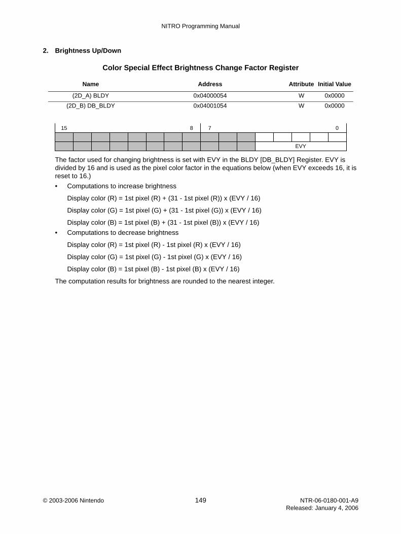
NITRO Programming Manual
2. Brightness Up/Down
Color Special Effect Brightness Change Factor Register
The factor used for changing brightness is set with EVY in the BLDY [DB_BLDY] Register. EVY is divided by 16 and is used as the pixel color factor in the equations below (when EVY exceeds 16, it is reset to 16.)• Computations to increase brightness
Display color (R) = 1st pixel (R) + (31 - 1st pixel (R)) x (EVY / 16)
Display color (G) = 1st pixel (G) + (31 - 1st pixel (G)) x (EVY / 16)
Display color (B) = 1st pixel (B) + (31 - 1st pixel (B)) x (EVY / 16)• Computations to decrease brightness
Display color (R) = 1st pixel (R) - 1st pixel (R) x (EVY / 16)
Display color (G) = 1st pixel (G) - 1st pixel (G) x (EVY / 16)
Display color (B) = 1st pixel (B) - 1st pixel (B) x (EVY / 16)
The computation results for brightness are rounded to the nearest integer.
Name Address Attribute Initial Value
(2D_A) BLDY 0x04000054 W 0x0000
(2D_B) DB_BLDY 0x04001054 W 0x0000
EVY
15 8 7 0
© 2003-2006 Nintendo 149 NTR-06-0180-001-A9Released: January 4, 2006
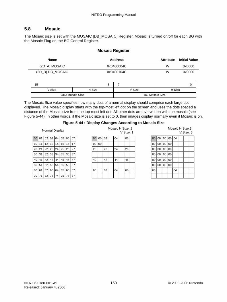
NITRO Programming Manual
5.8 MosaicThe Mosaic size is set with the MOSAIC [DB_MOSAIC] Register. Mosaic is turned on/off for each BG with the Mosaic Flag on the BG Control Register.
Mosaic Register
The Mosaic Size value specifies how many dots of a normal display should comprise each large dot displayed. The Mosaic display starts with the top-most left dot on the screen and uses the dots spaced a distance of the Mosaic size from the top-most left dot. All other dots are overwritten with the mosaic (see Figure 5-44). In other words, if the Mosaic size is set to 0, then images display normally even if Mosaic is on.
Figure 5-44 : Display Changes According to Mosaic Size
Name Address Attribute Initial Value
(2D_A) MOSAIC 0x0400004C W 0x0000
(2D_B) DB_MOSAIC 0x0400104C W 0x0000
V Size H Size V Size H Size
OBJ Mosaic Size BG Mosaic Size
15 8 7 0
Normal Display
01 02 03 04 05 06 07
11 12
21
13
22
30
14
23
31
40
15 16
24 25
17
26 27
32
41
33 34 35
42
50
45 46 47
55 56
65
57
66
75
67
76 77
60 61 62 63 64
70 71 72 73 74
51 52 53 54
36 37
43 44
00
10
20
00 02 04 06
00
22
40
24 26
42 46
6660 62 64
44
00
00
20
00 00 00 04
00 00 00
60 64
00
00
00 00 0000
00 00 0000
00 00 0000
00 00 0000
Mosaic H Size: 1V Size: 1
Mosaic H Size:3V Size: 5
NTR-06-0180-001-A9 150 © 2003-2006 NintendoReleased: January 4, 2006

NITRO Programming Manual
5.9 Display Priority• BG Display Priority
Four levels of display priority can be set for BGs with the BG Control Register. When BGs have the same priority, the one with the lower BG number has higher priority. The Backdrop screen always has the lowest priority.
• OBJ Display Priority
Four levels of display priority can be set for OBJs with the OBJ Attribute Data stored in OAM. When OBJs have the same priority, the one with the lower OBJ number has higher priority.
• BG - OBJ Display Priority
If an OBJ and a BG have the same priority, the OBJ has higher priority than the BG (see Figure 5-45).
Figure 5-45 : Display Priority
Workaround for the AGB OBJ Display Priority Problem
A problem with AGB caused an improper display when the OBJ numbers (the order OBJs are registered in OAM) and the OBJ priority levels were reversed. This problem is corrected in NITRO (unless NITRO is set to AGB-compatibility mode).
BG Priority 3Backdrop
BGPriority 2
BG Priority 1
BGPriority 0
OBJ Priority 3
OBJPriority 2
OBJPriority 1 OBJ Priority 0
Display PriorityHighLow
© 2003-2006 Nintendo 151 NTR-06-0180-001-A9Released: January 4, 2006

NITRO Programming Manual
NTR-06-0180-001-A9 152 © 2003-2006 NintendoReleased: January 4, 2006

NITRO Programming Manual
6 3D GraphicsFigure 6-1 is a schematic of the hardware block involved in the rendering of 3D graphics.
Figure 6-1 : 3D Graphics Hardware Block Diagram
Rendering Engine (RE)
Geometry Engine (GE)
Current Texture Matrix
GXFIFORegister
GXSTATRegister
Polygon List RAM Vertex RAM
Toon Table
Edge Color Table
BG0 Screen
Polygon List RAM
Counter
Specular Reflection Brightness Table
Texture Image Slot
Current Position Coordinate Matrix
Current Directional
Vector Matrix
Logic Memory
Matrix Stack Level 31
Matrix Stack Level 31
Stage 1
Depth Buffer
Rasterize
Texture Mapping
α-Blending
Stage 2
Fog
Edge Marking
Fog Blending Factor Table
Stencil Buffer
3D Graphics Registers/Memory
CommandFIFO
Command Register Group
(Stage 3 Current)
Color Buffer
(Stage 1 Current)
Current Projection
Matrix
Matrix Stack Level 1
Linked
Current Clip Coordinate
Matrix
(Stage 2 Current)
Stage 3Anti-Aliasing
Attribute Buffer
Texture Palette Slot
Vertex RAMCounter
Buffer
© 2003-2006 Nintendo 153 NTR-06-0180-001-A9Released: January 4, 2006

NITRO Programming Manual
• Polygon List RAM, Vertex RAM
The data that is passed from the Geometry Engine to the Rendering Engine is stored in Polygon List RAM and Vertex RAM.
Table 6-1 shows the capacity for this Polygon list RAM and Vertex RAM.
Table 6-1 : Capacity of Polygon List RAM and Vertex RAM
The capacity of polygon list RAM is just enough for 2048 triangular polygons. Because quadrilateral polygons have four vertices, fewer of these can be stored in this RAM. A maximum of 1706 can be stored for the quadrilateral strip because neighboring quadrilateral polygons share vertices.
• Buffers inside the Rendering Engine
The Stencil buffer, Attribute buffer, Depth buffer and Color buffer are memory regions that store information for each pixel. One buffer block in Figure 6-1 depicts a line buffer for an LCD horizontal line of 256 pixels. For more details, see the "6.3 Rendering Engine" on page 224.
RAM Capacity
Polygon List RAM 2048 polygons
Vertex RAM 6144 vertices
NTR-06-0180-001-A9 154 © 2003-2006 NintendoReleased: January 4, 2006
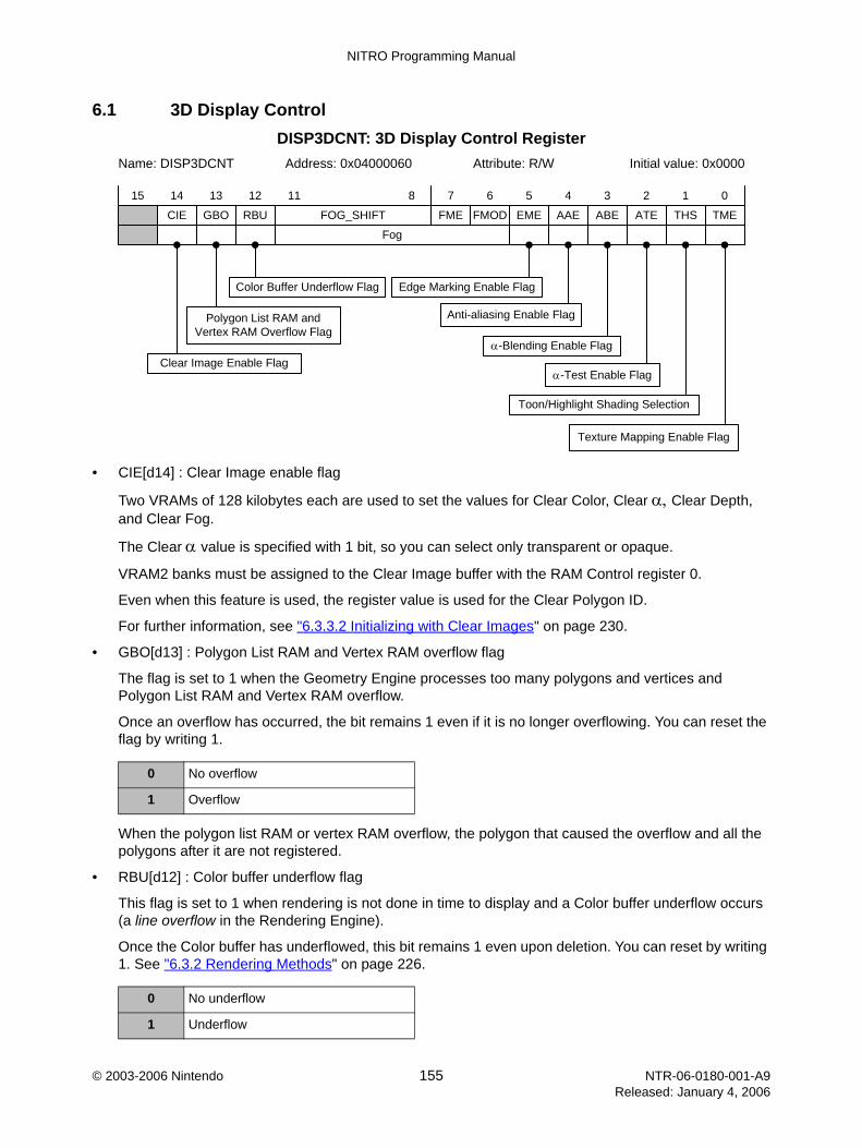
NITRO Programming Manual
6.1 3D Display ControlDISP3DCNT: 3D Display Control Register
Name: DISP3DCNT Address: 0x04000060 Attribute: R/W Initial value: 0x0000
• CIE[d14] : Clear Image enable flag
Two VRAMs of 128 kilobytes each are used to set the values for Clear Color, Clear α, Clear Depth, and Clear Fog.
The Clear α value is specified with 1 bit, so you can select only transparent or opaque.
VRAM2 banks must be assigned to the Clear Image buffer with the RAM Control register 0.
Even when this feature is used, the register value is used for the Clear Polygon ID.
For further information, see "6.3.3.2 Initializing with Clear Images" on page 230.
• GBO[d13] : Polygon List RAM and Vertex RAM overflow flag
The flag is set to 1 when the Geometry Engine processes too many polygons and vertices and Polygon List RAM and Vertex RAM overflow.
Once an overflow has occurred, the bit remains 1 even if it is no longer overflowing. You can reset the flag by writing 1.
When the polygon list RAM or vertex RAM overflow, the polygon that caused the overflow and all the polygons after it are not registered.
• RBU[d12] : Color buffer underflow flag
This flag is set to 1 when rendering is not done in time to display and a Color buffer underflow occurs (a line overflow in the Rendering Engine).
Once the Color buffer has underflowed, this bit remains 1 even upon deletion. You can reset by writing 1. See "6.3.2 Rendering Methods" on page 226.
0 No overflow
1 Overflow
0 No underflow
1 Underflow
CIE GBO RBU FOG_SHIFT FME FMOD EME AAE ABE ATE THS TME
Fog
15 14 13 12 11 8 7 6 5 4 3 2 1 0
Clear Image Enable Flag
Color Buffer Underflow Flag Edge Marking Enable Flag
Anti-aliasing Enable Flag
α-Blending Enable Flag
α-Test Enable Flag
Toon/Highlight Shading Selection
Texture Mapping Enable Flag
Polygon List RAM and Vertex RAM Overflow Flag
© 2003-2006 Nintendo 155 NTR-06-0180-001-A9Released: January 4, 2006
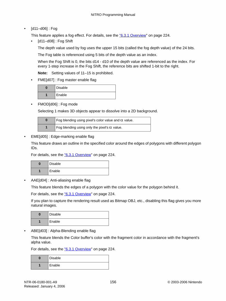
NITRO Programming Manual
• [d11–d06] : Fog
This feature applies a fog effect. For details, see the "6.3.1 Overview" on page 224.• [d11–d08] : Fog Shift
The depth value used by fog uses the upper 15 bits (called the fog depth value) of the 24 bits.
The Fog table is referenced using 5 bits of the depth value as an index.
When the Fog Shift is 0, the bits d14 - d10 of the depth value are referenced as the index. For every 1-step increase in the Fog Shift, the reference bits are shifted 1-bit to the right.
Note: Setting values of 11–15 is prohibited.
• FME[d07] : Fog master enable flag
• FMOD[d06] : Fog mode
Selecting 1 makes 3D objects appear to dissolve into a 2D background.
• EME[d05] : Edge-marking enable flag
This feature draws an outline in the specified color around the edges of polygons with different polygon IDs.
For details, see the "6.3.1 Overview" on page 224.
• AAE[d04] : Anti-aliasing enable flag
This feature blends the edges of a polygon with the color value for the polygon behind it.
For details, see the "6.3.1 Overview" on page 224.
If you plan to capture the rendering result used as Bitmap OBJ, etc., disabling this flag gives you more natural images.
• ABE[d03] : Alpha-Blending enable flag
This feature blends the Color buffer's color with the fragment color in accordance with the fragment's alpha value.
For details, see the "6.3.1 Overview" on page 224.
0 Disable
1 Enable
0 Fog blending using pixel's color value and α value.
1 Fog blending using only the pixel's α value.
0 Disable
1 Enable
0 Disable
1 Enable
0 Disable
1 Enable
NTR-06-0180-001-A9 156 © 2003-2006 NintendoReleased: January 4, 2006
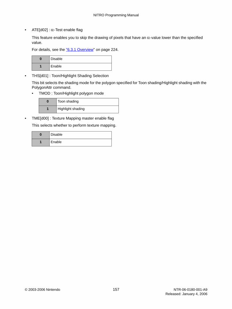
NITRO Programming Manual
• ATE[d02] : α-Test enable flag
This feature enables you to skip the drawing of pixels that have an α-value lower than the specified value.
For details, see the "6.3.1 Overview" on page 224.
• THS[d01] : Toon/Highlight Shading Selection
This bit selects the shading mode for the polygon specified for Toon shading/Highlight shading with the PolygonAttr command.• TMOD : Toon/Highlight polygon mode
• TME[d00] : Texture Mapping master enable flag
This selects whether to perform texture mapping.
0 Disable
1 Enable
0 Toon shading
1 Highlight shading
0 Disable
1 Enable
© 2003-2006 Nintendo 157 NTR-06-0180-001-A9Released: January 4, 2006
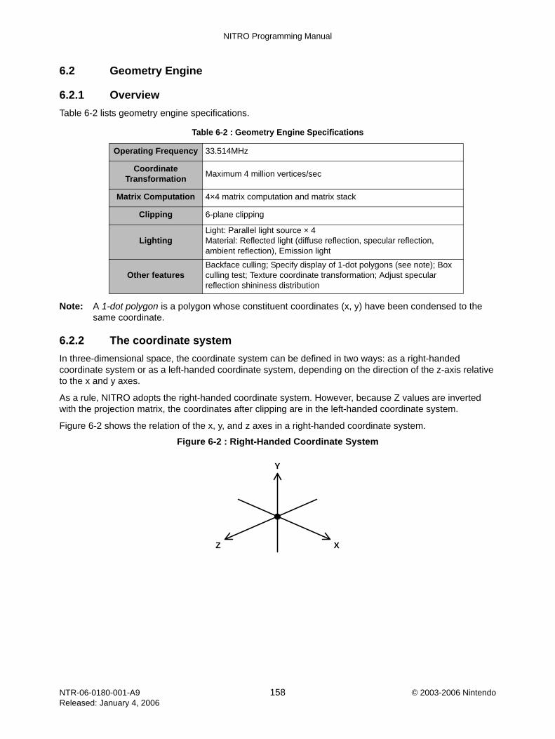
NITRO Programming Manual
6.2 Geometry Engine
6.2.1 OverviewTable 6-2 lists geometry engine specifications.
Table 6-2 : Geometry Engine Specifications
Note: A 1-dot polygon is a polygon whose constituent coordinates (x, y) have been condensed to the same coordinate.
6.2.2 The coordinate systemIn three-dimensional space, the coordinate system can be defined in two ways: as a right-handed coordinate system or as a left-handed coordinate system, depending on the direction of the z-axis relative to the x and y axes.
As a rule, NITRO adopts the right-handed coordinate system. However, because Z values are inverted with the projection matrix, the coordinates after clipping are in the left-handed coordinate system.
Figure 6-2 shows the relation of the x, y, and z axes in a right-handed coordinate system.
Figure 6-2 : Right-Handed Coordinate System
Operating Frequency 33.514MHz
Coordinate Transformation Maximum 4 million vertices/sec
Matrix Computation 4×4 matrix computation and matrix stack
Clipping 6-plane clipping
Lighting Light: Parallel light source × 4Material: Reflected light (diffuse reflection, specular reflection, ambient reflection), Emission light
Other featuresBackface culling; Specify display of 1-dot polygons (see note); Box culling test; Texture coordinate transformation; Adjust specular reflection shininess distribution
X
Y
Z
NTR-06-0180-001-A9 158 © 2003-2006 NintendoReleased: January 4, 2006
NITRO Programming Manual
6.2.3 Coordinate TransformationsIn OpenGL, when a model is located in view coordinates, the model is first multiplied by the model view matrix, which includes the view transformation. This is then multiplied by the projection matrix, and the apparent size of the model is determined based on the view volume.
To reduce the load on the hardware, NITRO uses a clip coordinate matrix that is a concatenation of the projection matrix and the position coordinates matrix, so that clip coordinate conversion is done with only one coordinate transformation. Then the clip coordinate values (x, y, z, w) are divided by 2w (perspective division) after only the w coordinate is translated to get the normalized screen coordinates, and a scaling transformation is done on the BG screen coordinates by a viewport transformation.
For the vertex's normal vector and light vector, OpenGL performs a transformation with the transposed matrix of the modelview matrix. In contrast, NITRO assumes the vector is normalized, and uses only the rotational component's matrix (the orthogonal matrix) for the transformation. This kind of transformation is called a directional vector transformation.
In OpenGL, vertex position coordinates and directional vectors are transformed into view coordinates just by setting the modelview matrix. But in NITRO, the vertex position coordinates and directional vectors are transformed by separate matrices, and these are separately defined as the position coordinates matrix and directional vector matrix.
© 2003-2006 Nintendo 159 NTR-06-0180-001-A9Released: January 4, 2006

NITRO Programming Manual
Figure 6-3 illustrates the coordinate transformation flow on the NITRO.
Figure 6-3 : Coordinate Transformation Flow Chart
Object Coordinates
Normalized Screen Coordinates
BG Screen Coordinates
Projection Transformation
Clip Coordinates
Perspective Division
Viewport Transformation
View Coordinates
Modeling Transformation
World Coordinates
Viewing Transformation
x
y
z
Object Coordinate System
Vertex coordinates specified with Vertex commands.
Sign + 3-bit integer + 12-bit fractional part
Clip Coordinate System
Clipped by view volume with an reversed z-axis.
Sign + 11-bit integer + 12-bit fractional part
Normalized Screen Coordinates
The x,y,z axes of the plane of projection (the near clip plane) are normalized to 0.0 to 1.0
BG Screen Coordinate System
Normalized screen coordinates are scaled, offset, and applied to the BG0 screen.The Y-axis is inverted when rendering with the Rendering Engine.
View Coordinate System
World space where the eye point is at the origin and the z-axis is opposite the line of sight.Sign + 16-bit integer + 12-bit fractional part
x
y
z
x
y
z
x
y
x
y
World Coordinate System
World space
Sign + 16-bit integer + 12-bit fractional part
x
y
z
Posi
tion
Coo
rdin
ates
Tr
ansf
orm
atio
n
Clip
Coo
rdin
ates
Tr
ansf
orm
atio
n
NTR-06-0180-001-A9 160 © 2003-2006 NintendoReleased: January 4, 2006

NITRO Programming Manual
6.2.4 Projection TransformationsThe perspective of the viewed polygon object from the eye point is defined by the view volume.
The view volumes and projection matrices for perspective projections (Figure 6-4) and orthogonal projections ("Figure 6-5 : Orthogonal Projections" on page 162) are described below.
1. Perspective ProjectionsFigure 6-4 : Perspective Projections
a. Left-Right Asymmetrical Perspective Projection
b. Left-Right Symmetrical Perspective Projection
Near Clip Plane
Eye Point
Far Clip Plane
Frustum
2nr l–------------ 0 0 0
02nt b–------------ 0 0
r l+r l–------------ t b+
t b–------------ f n+
f n–------------– 1–
0 02fnf n–------------– 0
scaleW×=
Perspective
θcosasp θsin⋅--------------------------- 0 0 0
0θcosθsin
------------- 0 0
0 0f n+f n–------------– 1–
0 02fnf n–------------– 0
scaleW×=
© 2003-2006 Nintendo 161 NTR-06-0180-001-A9Released: January 4, 2006
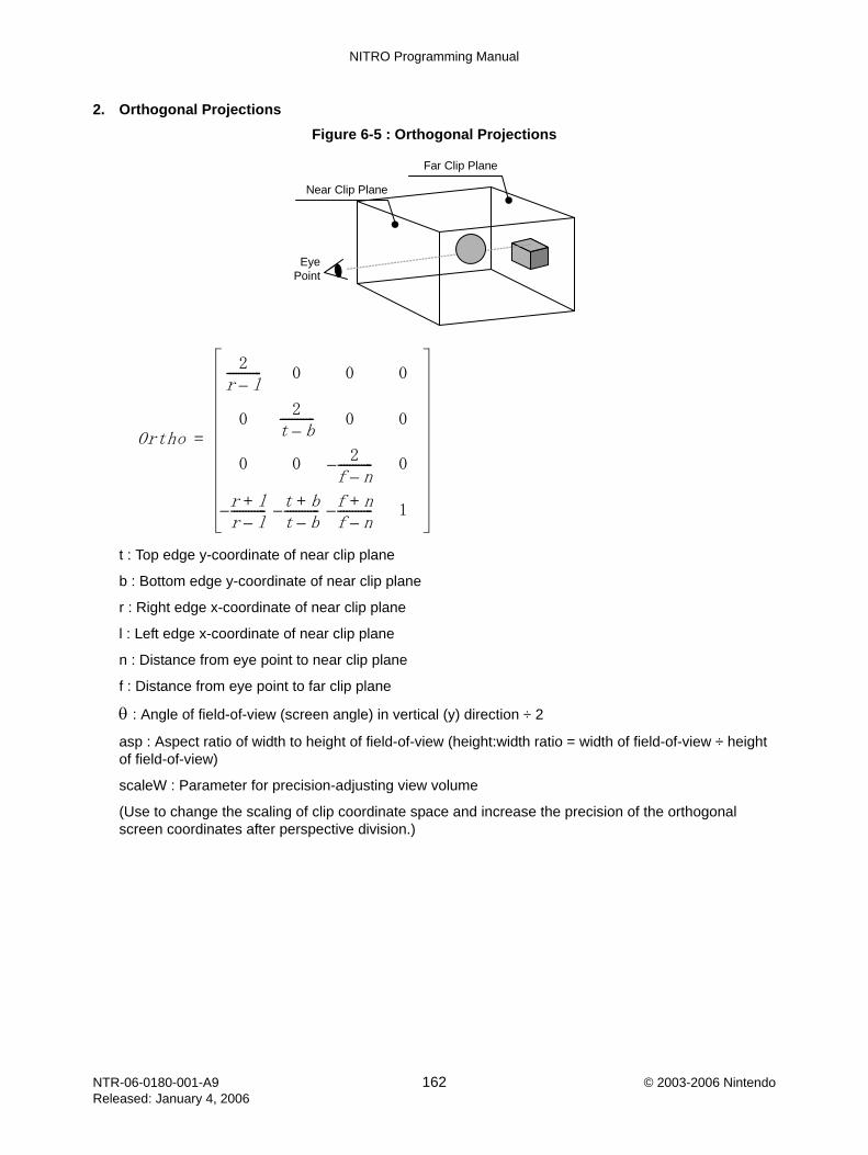
NITRO Programming Manual
2. Orthogonal ProjectionsFigure 6-5 : Orthogonal Projections
t : Top edge y-coordinate of near clip plane
b : Bottom edge y-coordinate of near clip plane
r : Right edge x-coordinate of near clip plane
l : Left edge x-coordinate of near clip plane
n : Distance from eye point to near clip plane
f : Distance from eye point to far clip plane
θ : Angle of field-of-view (screen angle) in vertical (y) direction ÷ 2
asp : Aspect ratio of width to height of field-of-view (height:width ratio = width of field-of-view ÷ height of field-of-view)
scaleW : Parameter for precision-adjusting view volume
(Use to change the scaling of clip coordinate space and increase the precision of the orthogonal screen coordinates after perspective division.)
Near Clip Plane
Eye Point
Far Clip Plane
Ortho
2r l–------------ 0 0 0
02
t b–------------ 0 0
0 02
f n–------------– 0
r l+r l–------------– t b+
t b–------------– f n+
f n–------------– 1
=
NTR-06-0180-001-A9 162 © 2003-2006 NintendoReleased: January 4, 2006

NITRO Programming Manual
6.2.5 Depth Buffering
1. For Perspective Projections
The perspective projection matrix parameters are set as shown below. (For details about elements p0-p5, see "6.2.4 Projection Transformations" on page 161).
When the View coordinates are (x, y, z, 1), the Clip coordinates (x’, y’, z’, w’) are as follows:
When each clip coordinate component is translated by w’ and then divided by 2w’ (perspective division), the normalized screen coordinates (x”, y”, z”, 1) are obtained. The z” component is calculated as follows:
p4 and p5 are elements of the perspective projection matrix, so using the matrix shown in the equation "a. Left-Right Asymmetrical Perspective Projection" on page 161 yields:
During Z buffering, this z” value is multiplied by 0x7FFF to get the depth value z’’’. The z’’’ value is proportional to the inverse of the View coordinate z value, so in View coordinate space the position coordinates are more precise the closer they are to the eye point, and less precise the farther they are away from the eye point. As a result, when you represent a large space, drawings that are farther away tend to be more imprecise. To resolve this problem, NITRO supports W buffering, which uses clip coordination as the depth value.
Because the depth value is taken as a multiple of the view coordinate z from the equation...
... the precision of rendering in the distance improves. The trade-off is that this diminishes the precision of nearby images compared to Z-buffering. But by enlarging the view volume space and adjusting scaleW in order to maintain a certain level of resolution, this should not present a problem for nearby images. (See Figure 6-6.)
M
p0 0 0 0
0 p2 0 0
p1 p3 p4 1–0 0 p5 0
scaleW×=
x' p0 x p1 z×+×( ) scaleW×=y' p2 y p3 z×+×( ) scaleW×=z' p4 z p5 1×+×( ) scaleW×=w' z scaleW×–=
z'' z' w'+2w'
-------------- p4 z p5 z–+×( ) scaleW×2z– scaleW×
-------------------------------------------------------------------- 12--- p4
2------– p5
2z------–= = =
z'' ff n–( )
---------------- 1nz---+⎝ ⎠
⎛ ⎞ far z near–≤ ≤–( )=
w' z scaleW far z≤– near–≤( )×–=
© 2003-2006 Nintendo 163 NTR-06-0180-001-A9Released: January 4, 2006
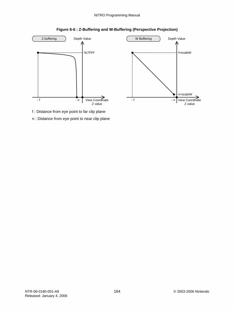
NITRO Programming Manual
Figure 6-6 : Z-Buffering and W-Buffering (Perspective Projection)
f : Distance from eye point to far clip plane
n : Distance from eye point to near clip plane
View Coordinate Z value
Z buffering W Buffering
View Coordinate Z value
-f
f×scaleW
-f -n
0x7FFF
-n
n×scaleW
Depth Value Depth Value
NTR-06-0180-001-A9 164 © 2003-2006 NintendoReleased: January 4, 2006
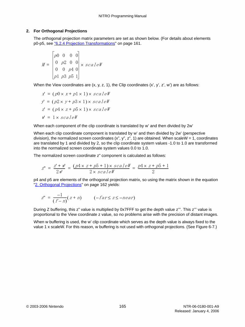
NITRO Programming Manual
2. For Orthogonal Projections
The orthogonal projection matrix parameters are set as shown below. (For details about elements p0-p5, see "6.2.4 Projection Transformations" on page 161.
When the View coordinates are (x, y, z, 1), the Clip coordinates (x’, y’, z’, w’) are as follows:
When each component of the clip coordinate is translated by w’ and then divided by 2w’
When each clip coordinate component is translated by w’ and then divided by 2w’ (perspective division), the normalized screen coordinates (x”, y”, z”, 1) are obtained. When scaleW = 1, coordinates are translated by 1 and divided by 2, so the clip coordinate system values -1.0 to 1.0 are transformed into the normalized screen coordinate system values 0.0 to 1.0.
The normalized screen coordinate z” component is calculated as follows:
p4 and p5 are elements of the orthogonal projection matrix, so using the matrix shown in the equation "2. Orthogonal Projections" on page 162 yields:
During Z buffering, this z” value is multiplied by 0x7FFF to get the depth value z’’’. This z’’’ value is proportional to the View coordinate z value, so no problems arise with the precision of distant images.
When w buffering is used, the w’ clip coordinate which serves as the depth value is always fixed to the value 1 x scaleW. For this reason, w buffering is not used with orthogonal projections. (See Figure 6-7.)
M
p0 0 0 0
0 p2 0 0
0 0 p4 0
p1 p3 p5 1
scaleW×=
x' p0 x p1 1×+×( ) scaleW×=y' p2 y p3 1×+×( ) scaleW×=z' p4 z p5 1×+×( ) scaleW×=w' 1 scaleW×=
z'' z' w'+2w'
-------------- p4 z p5 1+ +×( ) scaleW×2 scaleW×
-------------------------------------------------------------------- p4 z p5 1+ +×2
-------------------------------------= = =
z'' 1–f n–( )
---------------- z n+( ) far z near–≤ ≤–( )=
© 2003-2006 Nintendo 165 NTR-06-0180-001-A9Released: January 4, 2006
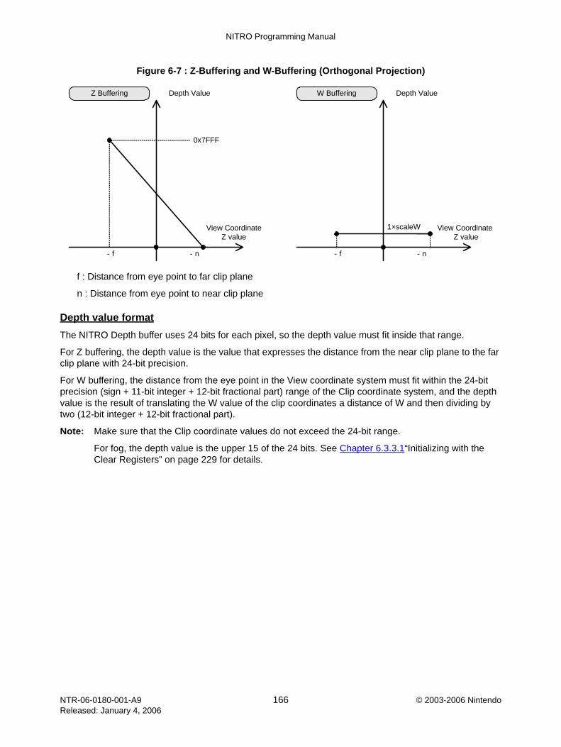
NITRO Programming Manual
Figure 6-7 : Z-Buffering and W-Buffering (Orthogonal Projection)
f : Distance from eye point to far clip plane
n : Distance from eye point to near clip plane
Depth value formatThe NITRO Depth buffer uses 24 bits for each pixel, so the depth value must fit inside that range.
For Z buffering, the depth value is the value that expresses the distance from the near clip plane to the far clip plane with 24-bit precision.
For W buffering, the distance from the eye point in the View coordinate system must fit within the 24-bit precision (sign + 11-bit integer + 12-bit fractional part) range of the Clip coordinate system, and the depth value is the result of translating the W value of the clip coordinates a distance of W and then dividing by two (12-bit integer + 12-bit fractional part).
Note: Make sure that the Clip coordinate values do not exceed the 24-bit range.
For fog, the depth value is the upper 15 of the 24 bits. See Chapter 6.3.3.1“Initializing with the Clear Registers” on page 229 for details.
View Coordinate Z value
-f
0x7FFF
View Coordinate Z value
-f
1×scaleW
-n
Z Buffering Depth Value W Buffering Depth Value
-n
NTR-06-0180-001-A9 166 © 2003-2006 NintendoReleased: January 4, 2006

NITRO Programming Manual
6.2.6 Geometry CommandsTo transfer the data of matrices and polygons, etc. to the Geometry Engine requires the writing of command strings to Command FIFO. There are two ways to write to Command FIFO:
Method 1: Write parameters to the group of command registers mapped in the register space of the main processor.
Write the parameters into Command registers, and the command code and parameters are automatically written into Command FIFO. This method works when the CPU will process one command at a time.
Method 2: Write command code and parameters to the Command FIFO register.
This method is appropriate for transferring large amounts of data to the Geometry Engine, such as for DMA transfers of command strings stored in main memory.
Note: The Geometry Command register group and Command FIFO are specialized for 32-bit access. Whether you are writing using the CPU or DMA, make sure the access width is 32 bits.
When an attempt is made to write to Command FIFO when it is full, the process enters a wait state until 32 bits open up in Command FIFO. During this wait state the bus cannot be used even by another bus master. You can avoid this situation by doing the following:
Transfer commands using the DMA Geometry Command FIFO startup mode
In this mode, DMA is started when Command FIFO becomes less than half full, sending in units of 112 words (see note) until the specified transfer volume is reached. See Chapter 7.
Note: If commands have been packed, the word count equals the number of words before unpacking.
You can determine the status of Command FIFO by checking the Command FIFO status flag in the Geometry Engine status register (GXSTAT).
© 2003-2006 Nintendo 167 NTR-06-0180-001-A9Released: January 4, 2006
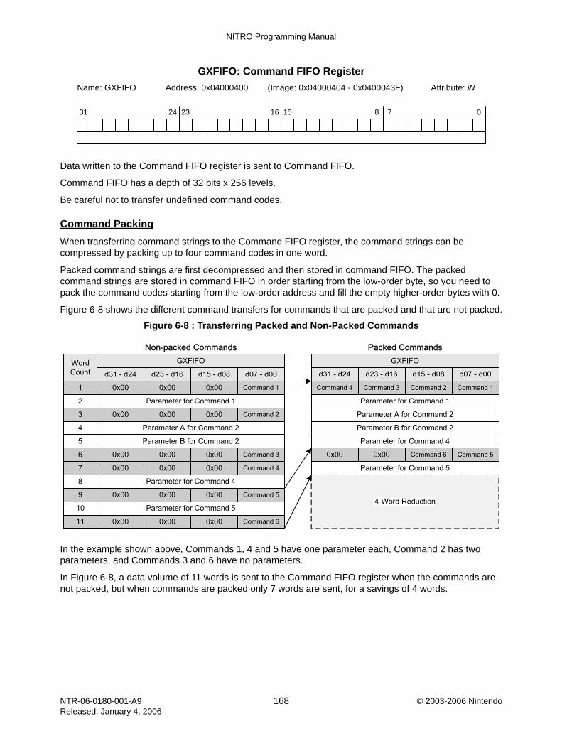
NITRO Programming Manual
GXFIFO: Command FIFO RegisterName: GXFIFO Address: 0x04000400 (Image: 0x04000404 - 0x0400043F) Attribute: W
Data written to the Command FIFO register is sent to Command FIFO.
Command FIFO has a depth of 32 bits x 256 levels.
Be careful not to transfer undefined command codes.
Command PackingWhen transferring command strings to the Command FIFO register, the command strings can be compressed by packing up to four command codes in one word.
Packed command strings are first decompressed and then stored in command FIFO. The packed command strings are stored in command FIFO in order starting from the low-order byte, so you need to pack the command codes starting from the low-order address and fill the empty higher-order bytes with 0.
Figure 6-8 shows the different command transfers for commands that are packed and that are not packed.
Figure 6-8 : Transferring Packed and Non-Packed Commands
In the example shown above, Commands 1, 4 and 5 have one parameter each, Command 2 has two parameters, and Commands 3 and 6 have no parameters.
In Figure 6-8, a data volume of 11 words is sent to the Command FIFO register when the commands are not packed, but when commands are packed only 7 words are sent, for a savings of 4 words.
31 24 23 16 15 8 7 0
Word Count
1
2
3
4
5
6
7
8
9
10
11
d31 - d24 d23 - d16 d15 - d08 d07 - d00
GXFIFO
0x00 0x00 0x00 Command 1
GXFIFO
Command 4 Command 3 Command 2 Command 1
Parameter for Command 1
0x00 0x00 0x00 Command 2
0x00 0x00 0x00 Command 3
0x00 0x00 0x00 Command 4
0x00 0x00 0x00 Command 5
0x00 0x00 0x00 Command 6
Parameter A for Command 2
Parameter B for Command 2
Parameter for Command 4
Parameter for Command 5
Parameter for Command 1
Parameter A for Command 2
Parameter B for Command 2
Parameter for Command 4
0x00 0x00 Command 6 Command 5
Parameter for Command 5
4-Word Reduction
Non-packed Commands Packed Commands
d31 - d24 d23 - d16 d15 - d08 d07 - d00
NTR-06-0180-001-A9 168 © 2003-2006 NintendoReleased: January 4, 2006
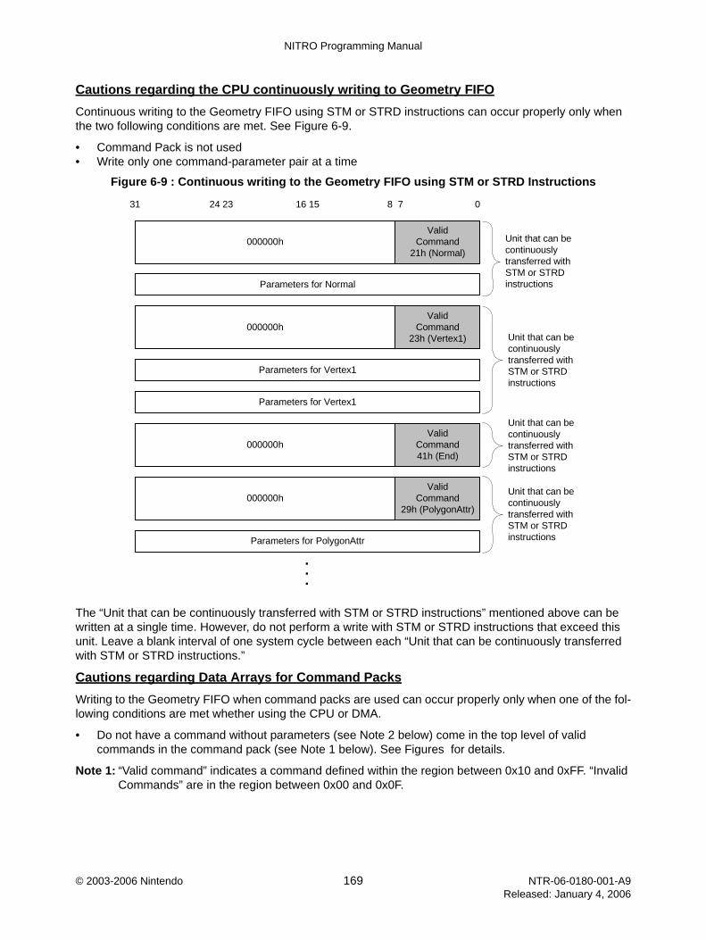
NITRO Programming Manual
Cautions regarding the CPU continuously writing to Geometry FIFOContinuous writing to the Geometry FIFO using STM or STRD instructions can occur properly only when the two following conditions are met. See Figure 6-9.
• Command Pack is not used • Write only one command-parameter pair at a time
Figure 6-9 : Continuous writing to the Geometry FIFO using STM or STRD Instructions
The “Unit that can be continuously transferred with STM or STRD instructions” mentioned above can be written at a single time. However, do not perform a write with STM or STRD instructions that exceed this unit. Leave a blank interval of one system cycle between each “Unit that can be continuously transferred with STM or STRD instructions.”
Cautions regarding Data Arrays for Command PacksWriting to the Geometry FIFO when command packs are used can occur properly only when one of the fol-lowing conditions are met whether using the CPU or DMA.
• Do not have a command without parameters (see Note 2 below) come in the top level of valid commands in the command pack (see Note 1 below). See Figures for details.
Note 1: “Valid command” indicates a command defined within the region between 0x10 and 0xFF. “Invalid Commands” are in the region between 0x00 and 0x0F.
000000hValid
Command21h (Normal)
000000hValid
Command23h (Vertex1)
000000hValid
Command41h (End)
000000hValid
Command29h (PolygonAttr)
Parameters for Normal
Parameters for Vertex1
Parameters for Vertex1
Parameters for PolygonAttr
31 24 23 16 15 8 7 0
.
.
.
Unit that can be continuously transferred with STM or STRD instructions
Unit that can be continuously transferred with STM or STRD instructions
Unit that can be continuously transferred with STM or STRD instructions
Unit that can be continuously transferred with STM or STRD instructions
© 2003-2006 Nintendo 169 NTR-06-0180-001-A9Released: January 4, 2006

NITRO Programming Manual
Note 2: A “command without parameters” is one of the four following commands.
• PushMatrix • LoadIdentity • End • Commands undefined within the region between 0x10 and 0xFF
Figure 6-10 : Case 1: Preventing Commands without Parameters from being the first Valid Command
ValidCommand
29h (PolygonAttr)
ValidCommand40h (Begin)
ValidCommand
22h (TexCoord)
.
.
.
.
.
.
Top Level of Valid Commands
ValidCommand
21h (Normal)
Parameters for Normal
31 24 23 16 15 8 7 0
Parameters for Vertex1
Parameters for Vertex1
ValidCommand
29h (PolygonAttr)
Parameters for PolygonAttr
ValidCommand
23h (Vertex1)
ValidCommand41h (End)
InvalidCommand
00h
ValidCommand40h (Begin)
ValidCommand
22h (TexCoord)
ValidCommand
23h (Vertex1)
ValidCommand
21h (Normal)
Parameters for Normal
31 24 23 16 15 8 7 0
Parameters for Vertex1
Parameters for Vertex1
Parameters for PolygonAttr
ValidCommand
23h (Vertex1)
ValidCommand41h (End)
InvalidCommand
00h
InvalidCommand
00h
NTR-06-0180-001-A9 170 © 2003-2006 NintendoReleased: January 4, 2006

NITRO Programming Manual
Figure 6-11 : Case 2: Preventing Commands without Parameters from being the first Valid Command
.
.
.
.
.
.
Not included in the command pack
ValidCommand
11h (PushMatrix)
31 24 23 16 15 8 7 0
ValidCommand
29h (PolygonAttr)
Parameters for PolygonAttr
ValidCommand
11h (PushMatrix)
ValidCommand
11h (PushMatrix)
ValidCommand
11h (PushMatrix)
ValidCommand40h (Begin)
ValidCommand
22h (TexCoord)
ValidCommand
23h (Vertex1)
Parameters for PolygonAttr
ValidCommand
11h (PushMatrix)
31 24 23 16 15 8 7 0
ValidCommand
11h (PushMatrix)
InvalidCommand
00h
InvalidCommand
00h
InvalidCommand
00h
ValidCommand
11h (PushMatrix)
ValidCommand
11h (PushMatrix)
ValidCommand
29h (PolygonAttr)
© 2003-2006 Nintendo 171 NTR-06-0180-001-A9Released: January 4, 2006

NITRO Programming Manual
• When a command without parameters comes in the top level of valid commands in the command pack, insert zeros at the end of the parameter array corresponding to that command pack.
Figure 6-12 : When the First Valid Command has no Parameters
Parameters for Vertex1
.
.
.
ValidCommand
21h (Normal)
31 24 23 16 15 8 7 0
ValidCommand
23h (Vertex1)
ValidCommand41h (End)
InvalidCommand
00h
Parameters for Normal
Parameters for Vertex1
Top Level of Valid Commands
Parameters for Vertex1
.
.
.
ValidCommand
21h (Normal)
31 24 23 16 15 8 7 0
ValidCommand
23h (Vertex1)
ValidCommand41h (End)
InvalidCommand
00h
Parameters for Normal
Parameters for Vertex1
All Zeros (0)
NTR-06-0180-001-A9 172 © 2003-2006 NintendoReleased: January 4, 2006
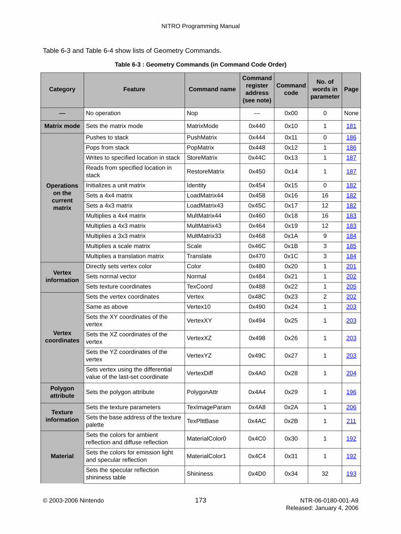
NITRO Programming Manual
Table 6-3 and Table 6-4 show lists of Geometry Commands.
Table 6-3 : Geometry Commands (in Command Code Order)
Category Feature Command name
Command register address
(see note)
Command code
No. of words in
parameterPage
— No operation Nop — 0x00 0 None
Matrix mode Sets the matrix mode MatrixMode 0x440 0x10 1 181
Operationson the current matrix
Pushes to stack PushMatrix 0x444 0x11 0 186
Pops from stack PopMatrix 0x448 0x12 1 186
Writes to specified location in stack StoreMatrix 0x44C 0x13 1 187
Reads from specified location in stack RestoreMatrix 0x450 0x14 1 187
Initializes a unit matrix Identity 0x454 0x15 0 182
Sets a 4x4 matrix LoadMatrix44 0x458 0x16 16 182
Sets a 4x3 matrix LoadMatrix43 0x45C 0x17 12 182
Multiplies a 4x4 matrix MultMatrix44 0x460 0x18 16 183
Multiplies a 4x3 matrix MultMatrix43 0x464 0x19 12 183
Multiplies a 3x3 matrix MultMatrix33 0x468 0x1A 9 184
Multiplies a scale matrix Scale 0x46C 0x1B 3 185
Multiplies a translation matrix Translate 0x470 0x1C 3 184
Vertex information
Directly sets vertex color Color 0x480 0x20 1 201
Sets normal vector Normal 0x484 0x21 1 202
Sets texture coordinates TexCoord 0x488 0x22 1 205
Vertex coordinates
Sets the vertex coordinates Vertex 0x48C 0x23 2 202
Same as above Vertex10 0x490 0x24 1 203
Sets the XY coordinates of the vertex VertexXY 0x494 0x25 1 203
Sets the XZ coordinates of the vertex VertexXZ 0x498 0x26 1 203
Sets the YZ coordinates of the vertex VertexYZ 0x49C 0x27 1 203
Sets vertex using the differential value of the last-set coordinate VertexDiff 0x4A0 0x28 1 204
Polygon attribute Sets the polygon attribute PolygonAttr 0x4A4 0x29 1 196
Texture information
Sets the texture parameters TexImageParam 0x4A8 0x2A 1 206
Sets the base address of the texture palette TexPlttBase 0x4AC 0x2B 1 211
Material
Sets the colors for ambient reflection and diffuse reflection MaterialColor0 0x4C0 0x30 1 192
Sets the colors for emission light and specular reflection MaterialColor1 0x4C4 0x31 1 192
Sets the specular reflection shininess table Shininess 0x4D0 0x34 32 193
© 2003-2006 Nintendo 173 NTR-06-0180-001-A9Released: January 4, 2006
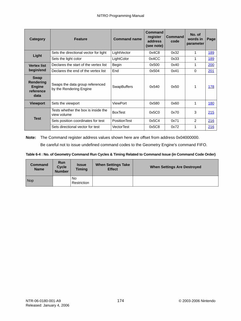
NITRO Programming Manual
Note: The Command register address values shown here are offset from address 0x04000000.
Be careful not to issue undefined command codes to the Geometry Engine's command FIFO.
Table 6-4 : No. of Geometry Command Run Cycles & Timing Related to Command Issue (in Command Code Order)
LightSets the directional vector for light LightVector 0x4C8 0x32 1 189
Sets the light color LightColor 0x4CC 0x33 1 189
Vertex list begin/end
Declares the start of the vertex list Begin 0x500 0x40 1 200
Declares the end of the vertex list End 0x504 0x41 0 201
Swap Rendering
Engine reference
data
Swaps the data group referenced by the Rendering Engine SwapBuffers 0x540 0x50 1 178
Viewport Sets the viewport ViewPort 0x580 0x60 1 180
Test
Tests whether the box is inside the view volume BoxTest 0x5C0 0x70 3 215
Sets position coordinates for test PositionTest 0x5C4 0x71 2 216
Sets directional vector for test VectorTest 0x5C8 0x72 1 216
Command Name
RunCycle
Number
Issue Timing
When Settings Take Effect When Settings Are Destroyed
Nop No Restriction
Category Feature Command name
Command register address
(see note)
Command code
No. of words in
parameterPage
NTR-06-0180-001-A9 174 © 2003-2006 NintendoReleased: January 4, 2006

NITRO Programming Manual
MatrixMode 1
No Restriction
When command is executed
When next MatrixMode command is executed
PushMatrix 17 When next Push/StoreMatrix command is executed
PopMatrix 36 When next Matrix change command is executed
StoreMatrix 17 When next Push/StoreMatrix command is executed
RestoreMatrix 36
When next Matrix change command is executed
Identity 19
LoadMatrix44 34
LoadMatrix43 30
MultMatrix44 35*
MultMatrix43 31*
MultMatrix33 28*
Scale 22
Translate 22*
Color 1When next Color, Normal command is executed
Normal 9 – 12**
TexCoord 1 When next TexCoord command is executed
Vertex 9
Only between Begin–End
When next Vertex related command is executed
VertexShort 8
VertexXY 8
VertexXZ 8
VertexYZ 8
VertexDiff 8
PolygonAttr 1
Only outside Begin – End
When Begin command is executed (settings are valid between Begin–End units)***
When next PolygonAttr command is executed
TexImageParam 1 Per
Polygon****
When command is executed (settings are valid in polygon units)
When next TexImageParam command is executed
TexPlttBase 1 When next TexPlttBase command is executed
MaterialColor0 4
No Restriction
When Normal command is executed
When next MaterialColor0 command is executed
MaterialColor1 4 When next MaterialColor1 command is executed
Shininess 32 When next Shininess command is executed
LightVector 6 When next LightVector command is executed
LightColor 1 When next LightColor command is executed
Begin 1 When command is executed
When next Begin command is executed
End 1 No set value
Command Name
RunCycle
Number
Issue Timing
When Settings Take Effect When Settings Are Destroyed
© 2003-2006 Nintendo 175 NTR-06-0180-001-A9Released: January 4, 2006
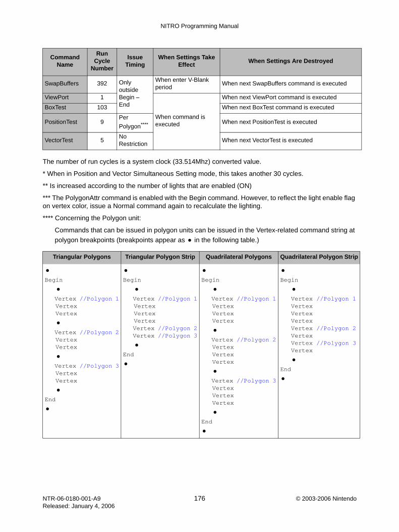
NITRO Programming Manual
The number of run cycles is a system clock (33.514Mhz) converted value.
* When in Position and Vector Simultaneous Setting mode, this takes another 30 cycles.
** Is increased according to the number of lights that are enabled (ON)
*** The PolygonAttr command is enabled with the Begin command. However, to reflect the light enable flag on vertex color, issue a Normal command again to recalculate the lighting.
**** Concerning the Polygon unit:
Commands that can be issued in polygon units can be issued in the Vertex-related command string at polygon breakpoints (breakpoints appear as • in the following table.)
SwapBuffers 392 Only outside Begin – End
When enter V-Blank period When next SwapBuffers command is executed
ViewPort 1
When command is executed
When next ViewPort command is executed
BoxTest 103 When next BoxTest command is executed
PositionTest 9Per Polygon**** When next PositionTest is executed
VectorTest 5 No Restriction When next VectorTest is executed
Triangular Polygons Triangular Polygon Strip Quadrilateral Polygons Quadrilateral Polygon Strip
•Begin
• Vertex //Polygon 1 Vertex Vertex
• Vertex //Polygon 2 Vertex Vertex
• Vertex //Polygon 3 Vertex Vertex
•End
•
•Begin
• Vertex //Polygon 1 Vertex Vertex Vertex Vertex //Polygon 2 Vertex //Polygon 3
•End
•
•Begin
• Vertex //Polygon 1 Vertex Vertex Vertex
• Vertex //Polygon 2 Vertex Vertex Vertex
• Vertex //Polygon 3 Vertex Vertex Vertex
•End
•
•Begin
• Vertex //Polygon 1 Vertex Vertex Vertex Vertex //Polygon 2 Vertex Vertex //Polygon 3 Vertex
•End
•
Command Name
RunCycle
Number
Issue Timing
When Settings Take Effect When Settings Are Destroyed
NTR-06-0180-001-A9 176 © 2003-2006 NintendoReleased: January 4, 2006

NITRO Programming Manual
C
Bc
C
C
C
TC
LC
LiC
MaC
SC
VC
PTex
C
Figure 6-13 shows a schematic of the main Geometry Command processes.
Figure 6-13 : Schematic of the main Geometry Command processes
Note: The flow shown here for the TexCoord command is for when the texture coordinate transformation mode is set to TexCoord source.
Current Texture Matrix
Specular Reflection Shininess Table
Current Position Coordinate Matrix
Current Directional Vector Matrix
Matrix StackLevel 31
Matrix StackLevel 31
Current Projection Matrix
Matrix StackLevel 1
Linked
Current Clip Coordinate Matrix
Current Viewport
Clip Coordinate Transformation
Vector coordinate transformation Lighting
Viewport Transformation
Matrix ommands
Current Vertex Color
Current texture coordinates
Vertex RAM
Current Light Color
Current Light Vector
Current Material Color
Polygon List RAM
Vector Coordinate
Transformation
Ren
derin
g En
gine
egin, Endommands
Vertex ommands
Normalommand
Colorommand
exCoordommand
ightColorommand
ghtVectorommand
terialColorommand
hininessommand
iewportommand
olygonAttr,ImageParamommands
Current Attribute
When the Begin Command is Processed
Register Can be Read
Register Can be Read
Automatically Concatenated
Perspective Division
When Vertex Color for Diffuse Color is Set
Texture Coordinate Transformation
Prim
itive
Tra
nsla
tion
Maximum 6144 Vertices
Maximum 2048 Polygons
© 2003-2006 Nintendo 177 NTR-06-0180-001-A9Released: January 4, 2006

NITRO Programming Manual
6.2.7 Swapping the Rendering Engine's Reference Data
SwapBuffers: Swaps the Data Group Referenced by the Rendering EngineName: SWAP_BUFFERS Address: 0x04000540 Attribute: W Command Code: 0x50
• DP[d01] : Depth buffering selection flag
Selects the value used for the depth test. To read how the depth value differs depending on the depth-buffering method, see "6.2.5 Depth Buffering" on page 163.
• YS[d00] : Translucent polygon Y-sorting selection flag
Translucent polygons are polygons with (1 ≤ α ≤ 30) or mapped with a translucent texture.
Select manual sort mode to specify the order of rendering, such as when using shadow volume.
The Geometry Engine writes the data passed to the Rendering Engine to Polygon List RAM.
For translucent polygons, you can choose whether to sort the data and then write, or to simply write the data in the order they are processed, without sorting. In Auto-sort mode, polygons are sorted from the polygon with smallest maximum Y value on the LCD (see note) to the polygon with the largest maximum Y value. Polygons that share the same maximum Y value are sorted in order from the polygon with smallest minimum Y value.
In Manual sort mode, polygons are sorted according to the order in which they are sent to the Geometry Engine.
In Auto sort mode, the Rendering Engine does not reference polygons with minimum Y values larger than the scan line (a line that is being rendered) or polygons with maximum Y values smaller than the scan line. However, all polygons are referenced in manual mode, which increases the load on the geometry engine (and reduces rendering efficiency). Because of this, be careful when using Manual sort mode when there are a large number of translucent polygons.
Opaque polygons are always Auto sorted.
Regardless of the sort mode, opaque polygons are always rendered before translucent polygons.
Note: Maximum Polygon Y value on the LCD
The Y coordinates are the inverse of Y coordinates in the BG Screen Coordinate Group in the Coordinate Transformation Flow Chart (Figure 6-3). Therefore, the maximum Y value for a polygon on the LCD is the minimum value in the BG Screen Coordinate Group.
0 Select buffering with the Z value
1 Select buffering with the W value(Does not function properly for orthogonal projections)
0 Auto-sort mode
1 Manual sort mode
DP YS
31 24 23 16 15 8 7 1 0
NTR-06-0180-001-A9 178 © 2003-2006 NintendoReleased: January 4, 2006

NITRO Programming Manual
• Reflecting the Depth Buffering Select Flag and Translucent Polygon Y Sorting Select Flag
These flags are reflected in the geometry engine from the next frame. However, because polygon list RAM and vertex RAM are double buffered, the rendering engine renders the data that the geometry engine stored in the previous frame. Therefore, data that the geometry engine outputs is rendered with an additional one-frame delay.
• Processing the SwapBuffers command
The SwapBuffers command is processed at the next V-Blank, regardless of when it was input. (The geometry engine is in wait status until the V-Blank period arrives.) The Polygon List RAM, Vertex RAM, rendering-related registers, and other data referenced by the Rendering Engine is swapped at the start of the next V-Blank period after the issuance of the SwapBuffers command. Because of this timing, rendering reflects the written graphics data in the next frame after the SwapBuffers command is issued.
© 2003-2006 Nintendo 179 NTR-06-0180-001-A9Released: January 4, 2006
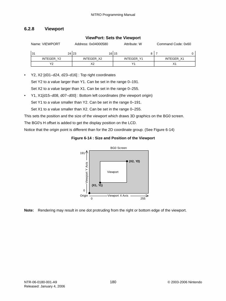
NITRO Programming Manual
6.2.8 Viewport
ViewPort: Sets the ViewportName: VIEWPORT Address: 0x04000580 Attribute: W Command Code: 0x60
• Y2, X2 [d31–d24, d23–d16] : Top right coordinates
Set Y2 to a value larger than Y1. Can be set in the range 0–191.
Set X2 to a value larger than X1. Can be set in the range 0–255.
• Y1, X1[d15–d08, d07–d00] : Bottom left coordinates (the viewport origin)
Set Y1 to a value smaller than Y2. Can be set in the range 0–191.
Set X1 to a value smaller than X2. Can be set in the range 0–255.
This sets the position and the size of the viewport which draws 3D graphics on the BG0 screen.
The BG0's H offset is added to get the display position on the LCD.
Notice that the origin point is different than for the 2D coordinate group. (See Figure 6-14)
Figure 6-14 : Size and Position of the Viewport
Note: Rendering may result in one dot protruding from the right or bottom edge of the viewport.
INTEGER_Y2 INTEGER_X2 INTEGER_Y1 INTEGER_X1
Y2 X2 Y1 X1
31 24 23 16 15 8 7 0
Viewport
0 255
191
0
Viewport X Axis
Vie
wpo
rt Y
Axi
s
BG0 Screen
Origin
(X1, Y1)
(X2, Y2)
NTR-06-0180-001-A9 180 © 2003-2006 NintendoReleased: January 4, 2006
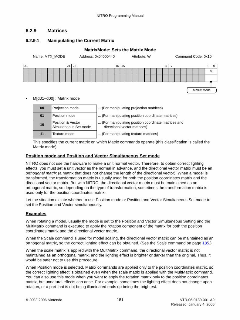
NITRO Programming Manual
6.2.9 Matrices
6.2.9.1 Manipulating the Current Matrix
MatrixMode: Sets the Matrix ModeName: MTX_MODE Address: 0x04000440 Attribute: W Command Code: 0x10
• M[d01–d00] : Matrix mode
This specifies the current matrix on which Matrix commands operate (this classification is called the Matrix mode).
Position mode and Position and Vector Simultaneous Set modeNITRO does not use the hardware to make a unit normal vector. Therefore, to obtain correct lighting effects, you must set a unit vector as the normal in advance, and the directional vector matrix must be an orthogonal matrix (a matrix that does not change the length of the directional vector). When a model is transformed, the transformation matrix is usually used for both the position coordinates matrix and the directional vector matrix. But with NITRO, the directional vector matrix must be maintained as an orthogonal matrix, so depending on the type of transformation, sometimes the transformation matrix is used only for the position coordinates matrix.
Let the situation dictate whether to use Position mode or Position and Vector Simultaneous Set mode to set the Position and Vector simultaneously.
ExamplesWhen rotating a model, usually the mode is set to the Position and Vector Simultaneous Setting and the MultMatrix command is executed to apply the rotation component of the matrix for both the position coordinates matrix and the directional vector matrix.
When the Scale command is used for model scaling, the directional vector matrix can be maintained as an orthogonal matrix, so the correct lighting effect can be obtained. (See the Scale command on page 185.)
When the scale matrix is applied with the MultMatrix command, the directional vector matrix is not maintained as an orthogonal matrix, and the lighting effect is brighter or darker than the original. Thus, it would be safer not to use this procedure.
When Position mode is selected, Matrix commands are applied only to the position coordinates matrix, so the correct lighting effect is obtained even when the scale matrix is applied with the MultMatrix command. You can also use this mode when you want to apply the rotation matrix only to the position coordinates matrix, but unnatural effects can arise. For example, sometimes the lighting effect does not change upon rotation, or a part that is not being illuminated ends up being the brightest.
00 Projection mode ... (For manipulating projection matrices)
01 Position mode ... (For manipulating position coordinate matrices)
10 Position & Vector Simultaneous Set mode
... (For manipulating position coordinate matrices and directional vector matrices)
11 Texture mode ... (For manipulating texture matrices)
31 24 23 16 15 8 7 1 0
M
Matrix Mode
© 2003-2006 Nintendo 181 NTR-06-0180-001-A9Released: January 4, 2006
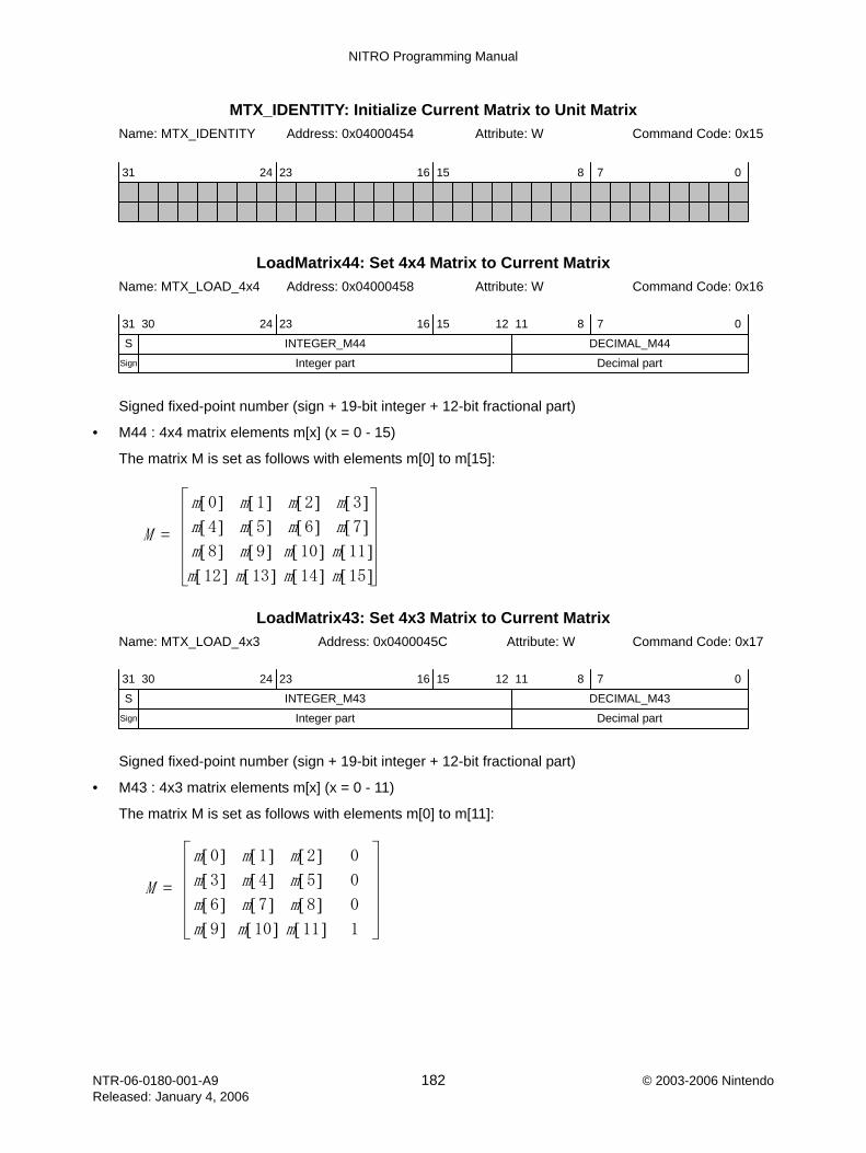
NITRO Programming Manual
MTX_IDENTITY: Initialize Current Matrix to Unit MatrixName: MTX_IDENTITY Address: 0x04000454 Attribute: W Command Code: 0x15
LoadMatrix44: Set 4x4 Matrix to Current MatrixName: MTX_LOAD_4x4 Address: 0x04000458 Attribute: W Command Code: 0x16
Signed fixed-point number (sign + 19-bit integer + 12-bit fractional part)
• M44 : 4x4 matrix elements m[x] (x = 0 - 15)
The matrix M is set as follows with elements m[0] to m[15]:
LoadMatrix43: Set 4x3 Matrix to Current MatrixName: MTX_LOAD_4x3 Address: 0x0400045C Attribute: W Command Code: 0x17
Signed fixed-point number (sign + 19-bit integer + 12-bit fractional part)
• M43 : 4x3 matrix elements m[x] (x = 0 - 11)
The matrix M is set as follows with elements m[0] to m[11]:
31 24 23 16 15 8 7 0
S INTEGER_M44 DECIMAL_M44Sign Integer part Decimal part
31 30 24 23 16 15 12 11 8 7 0
M
m 0[ ] m 1[ ] m 2[ ] m 3[ ]m 4[ ] m 5[ ] m 6[ ] m 7[ ]m 8[ ] m 9[ ] m 10[ ] m 11[ ]m 12[ ] m 13[ ] m 14[ ] m 15[ ]
=
S INTEGER_M43 DECIMAL_M43Sign Integer part Decimal part
31 30 24 23 16 15 12 11 8 7 0
M
m 0[ ] m 1[ ] m 2[ ] 0
m 3[ ] m 4[ ] m 5[ ] 0
m 6[ ] m 7[ ] m 8[ ] 0
m 9[ ] m 10[ ] m 11[ ] 1
=
NTR-06-0180-001-A9 182 © 2003-2006 NintendoReleased: January 4, 2006
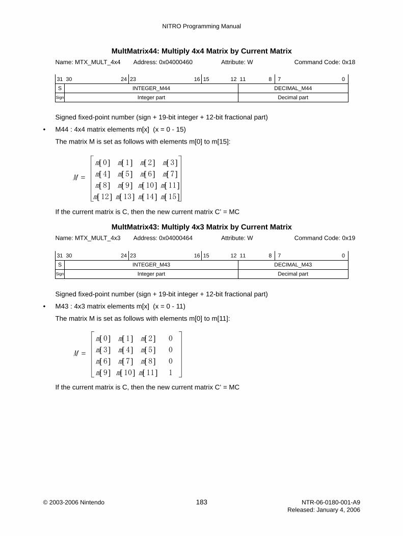
NITRO Programming Manual
MultMatrix44: Multiply 4x4 Matrix by Current MatrixName: MTX_MULT_4x4 Address: 0x04000460 Attribute: W Command Code: 0x18
Signed fixed-point number (sign + 19-bit integer + 12-bit fractional part)
• M44 : 4x4 matrix elements m[x] (x = 0 - 15)
The matrix M is set as follows with elements m[0] to m[15]:
If the current matrix is C, then the new current matrix C’ = MC
MultMatrix43: Multiply 4x3 Matrix by Current MatrixName: MTX_MULT_4x3 Address: 0x04000464 Attribute: W Command Code: 0x19
Signed fixed-point number (sign + 19-bit integer + 12-bit fractional part)
• M43 : 4x3 matrix elements m[x] (x = 0 - 11)
The matrix M is set as follows with elements m[0] to m[11]:
If the current matrix is C, then the new current matrix C’ = MC
S INTEGER_M44 DECIMAL_M44Sign Integer part Decimal part
31 30 24 23 16 15 12 11 8 7 0
M
m 0[ ] m 1[ ] m 2[ ] m 3[ ]m 4[ ] m 5[ ] m 6[ ] m 7[ ]m 8[ ] m 9[ ] m 10[ ] m 11[ ]m 12[ ] m 13[ ] m 14[ ] m 15[ ]
=
S INTEGER_M43 DECIMAL_M43Sign Integer part Decimal part
31 30 24 23 16 15 12 11 8 7 0
M
m 0[ ] m 1[ ] m 2[ ] 0
m 3[ ] m 4[ ] m 5[ ] 0
m 6[ ] m 7[ ] m 8[ ] 0
m 9[ ] m 10[ ] m 11[ ] 1
=
© 2003-2006 Nintendo 183 NTR-06-0180-001-A9Released: January 4, 2006
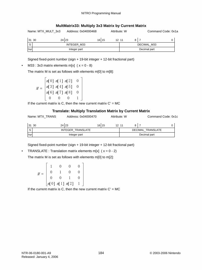
NITRO Programming Manual
MultMatrix33: Multiply 3x3 Matrix by Current MatrixName: MTX_MULT_3x3 Address: 0x04000468 Attribute: W Command Code: 0x1a
Signed fixed-point number (sign + 19-bit integer + 12-bit fractional part)
• M33 : 3x3 matrix elements m[x] ( x = 0 - 8)
The matrix M is set as follows with elements m[0] to m[8]:
If the current matrix is C, then the new current matrix C’ = MC
Translate: Multiply Translation Matrix by Current MatrixName: MTX_TRANS Address: 0x04000470 Attribute: W Command Code: 0x1c
Signed fixed-point number (sign + 19-bit integer + 12-bit fractional part)
• TRANSLATE : Translation matrix elements m[x] ( x = 0 - 2)
The matrix M is set as follows with elements m[0] to m[2]:
If the current matrix is C, then the new current matrix C’ = MC
S INTEGER_M33 DECIMAL_M33Sign Integer part Decimal part
31 30 24 23 16 15 12 11 8 7 0
M
m 0[ ] m 1[ ] m 2[ ] 0
m 3[ ] m 4[ ] m 5[ ] 0
m 6[ ] m 7[ ] m 8[ ] 0
0 0 0 1
=
S INTEGER_TRANSLATE DECIMAL_TRANSLATESign Integer part Decimal part
31 30 24 23 16 15 12 11 8 7 0
M
1 0 0 0
0 1 0 0
0 0 1 0
m 0[ ] m 1[ ] m 2[ ] 1
=
NTR-06-0180-001-A9 184 © 2003-2006 NintendoReleased: January 4, 2006

NITRO Programming Manual
Scale: Multiply the Scale Matrix by Current MatrixName: MTX_SCALE Address: 0x0400046C Attribute: W Command Code: 0x1b
Signed fixed-point number (sign + 19-bit integer + 12-bit fractional part)
• SCALE : Scale matrix elements m[x] ( x = 0 - 2)
The matrix M is set as follows with elements m[0] to m[2]:
If the current matrix is C, then the new current matrix C’ = MC
The Scale command performs multiplication only on the position coordinates matrix, even when the matrix mode has been set to Position & Vector Simultaneous Setting mode. (If it were performed on the directional vector matrix, the direction and length of vectors would change and abnormal lighting effects would arise.)
S INTEGER_SCALE DECIMAL_SCALESign Integer part Decimal part
31 30 24 23 16 15 12 11 8 7 0
M
m 0[ ] 0 0 0
0 m 1[ ] 0 0
0 0 m 2[ ] 0
0 0 0 1
=
© 2003-2006 Nintendo 185 NTR-06-0180-001-A9Released: January 4, 2006

NITRO Programming Manual
6.2.9.2 Matrix StackManipulations are made to the stack of the current matrix.
Because the position coordination matrix stack and the directional vector matrix stack are connected, manipulations affect both stacks, whether the mode is set to Position mode or Position & Vector Simultaneous Setting mode.
PushMatrix: Push the Current Matrix on the StackName: MTX_PUSH Address: 0x04000444 Attribute: W Command Code: 0x11
PopMatrix: Pop the Current Matrix from the StackName: MTX_POP Address: 0x04000448 Attribute: W Command Code: 0x12
Signed integer (sign + 5-bit integer)
• NUM[d05–d00] : Specify the number of pops (Can set a value of -30 to 31)
Pops the nth level matrix (as specified by NUM), starting from the position of the stack pointer of the matrix stack specified by the Matrix mode, and sets it as the current matrix.
When the Matrix mode is set to projection mode, the stack only has 1 level so the value of NUM is treated as 1, no matter what value has been set.
This command is normally issued outside of the command string that runs from Begin to End, but it can also be issued between Vertex commands within the Begin to End command string.
In Command string Example 2, the PopMatrix command is issued between Vertex commands to realize stitching and sprite polygon deformations. Stitching is a type of skinning. Sprite polygons are polygons displayed in 2D.
Command String Example 1 PushMatrix→Translate→Begin→Vertex→Vertex→Vertex→End→PopMatrix (1)
Command String Example 2
PushMatrix→Translate→PushMatrix→Begin→Vertex→PopMatrix (1)→Vertex→ PopMatrix (-1)→Vertex→PopMatrix (1)→Vertex→End→PopMatrix (1)
31 24 23 16 15 8 7 0
S INT
NUM number of pops
31 24 23 16 15 8 7 0
NTR-06-0180-001-A9 186 © 2003-2006 NintendoReleased: January 4, 2006
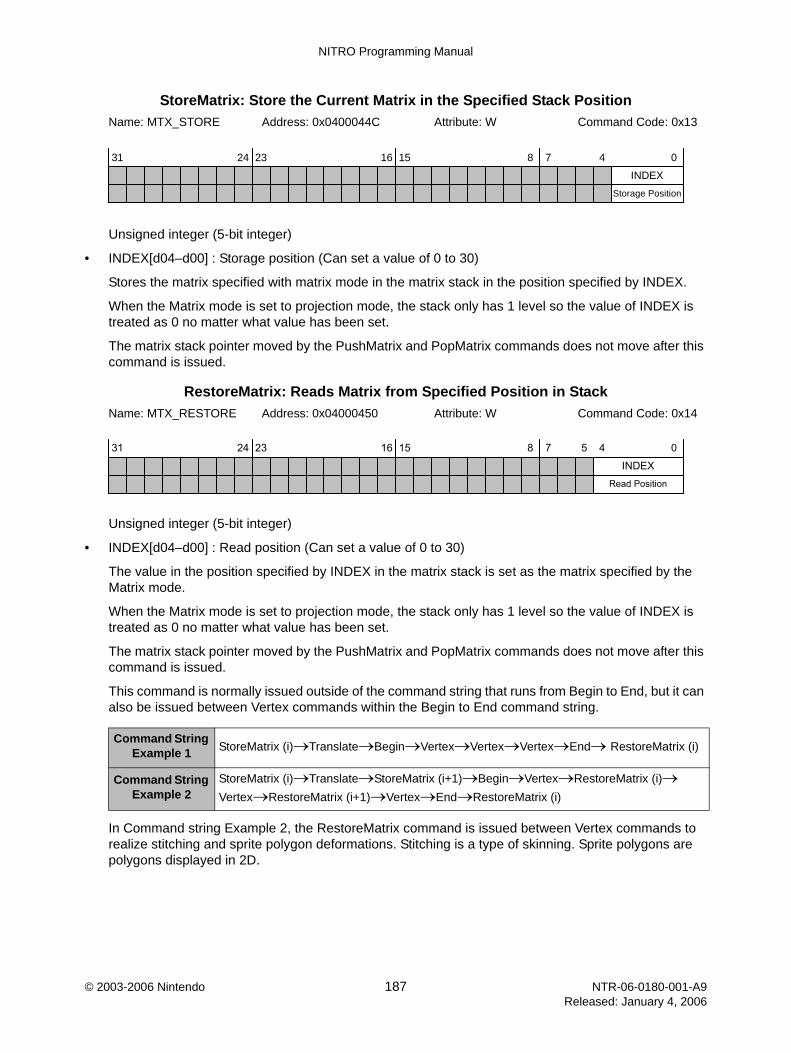
NITRO Programming Manual
StoreMatrix: Store the Current Matrix in the Specified Stack PositionName: MTX_STORE Address: 0x0400044C Attribute: W Command Code: 0x13
Unsigned integer (5-bit integer)
• INDEX[d04–d00] : Storage position (Can set a value of 0 to 30)
Stores the matrix specified with matrix mode in the matrix stack in the position specified by INDEX.
When the Matrix mode is set to projection mode, the stack only has 1 level so the value of INDEX is treated as 0 no matter what value has been set.
The matrix stack pointer moved by the PushMatrix and PopMatrix commands does not move after this command is issued.
RestoreMatrix: Reads Matrix from Specified Position in StackName: MTX_RESTORE Address: 0x04000450 Attribute: W Command Code: 0x14
Unsigned integer (5-bit integer)
• INDEX[d04–d00] : Read position (Can set a value of 0 to 30)
The value in the position specified by INDEX in the matrix stack is set as the matrix specified by the Matrix mode.
When the Matrix mode is set to projection mode, the stack only has 1 level so the value of INDEX is treated as 0 no matter what value has been set.
The matrix stack pointer moved by the PushMatrix and PopMatrix commands does not move after this command is issued.
This command is normally issued outside of the command string that runs from Begin to End, but it can also be issued between Vertex commands within the Begin to End command string.
In Command string Example 2, the RestoreMatrix command is issued between Vertex commands to realize stitching and sprite polygon deformations. Stitching is a type of skinning. Sprite polygons are polygons displayed in 2D.
Command String Example 1 StoreMatrix (i)→Translate→Begin→Vertex→Vertex→Vertex→End→ RestoreMatrix (i)
Command String Example 2
StoreMatrix (i)→Translate→StoreMatrix (i+1)→Begin→Vertex→RestoreMatrix (i)→ Vertex→RestoreMatrix (i+1)→Vertex→End→RestoreMatrix (i)
INDEXStorage Position
31 24 23 16 15 8 7 4 0
INDEXRead Position
31 24 23 16 15 8 7 4 05
© 2003-2006 Nintendo 187 NTR-06-0180-001-A9Released: January 4, 2006

NITRO Programming Manual
6.2.9.3 Reading the Current MatrixClipMatrix_Result: Read the Current Clip Coordinates Matrix
Signed fixed-point number (sign + 19-bit integer + 12-bit fractional part)
• m[x] (x = 0–15) : The elements of the current clip coordinates matrix
The current clip coordinates matrix (position coordinate matrix and projection matrix) can be read.
If you want to read the current projection matrix, make the current position coordinates matrix a unit matrix and read this register.
If you want to read the current position coordinates matrix, make the current projection matrix a unit matrix and read this register.
To safely read these matrices, confirmation that the Geometry Engine is stopped must occur before reading.
VectorMatrix: Read the Current Directional Vector Matrix
Signed fixed-point number (sign + 19-bit integer + 12-bit fractional part)
• m[x] (x = 0 - 8) : The elements of the current directional vector matrix
Note: To safely read this matrix, first confirm that the Geometry Engine is stopped.
Name Address Attribute Initial Value
CLIPMTX_RESULT_x (x=0-15)
0x04000640, 0x04000644, 0x04000648, 0x0400064C, 0x04000650, 0x04000654, 0x04000658, 0x0400065C, 0x04000660, 0x04000664, 0x04000668, 0x0400066C, 0x04000670, 0x04000674, 0x04000678, 0x0400067C
R 0x00000000
Name Address Attribute Initial Value
VECMTX_RESULT_x (x =0-8)0x04000680, 0x04000684, 0x04000688, 0x0400068C, 0x04000690, 0x04000694, 0x04000698, 0x0400069C,
0x040006A0R 0x00000000
S DECIMAL_m[x]Sign Integer part Decimal part
31 30 24 23 16 15 12 11 8 7 0
INTEGER_m[x]
CurrentClipCoordinatesMatrix
m 0[ ] m 1[ ] m 2[ ] m 3[ ]m 4[ ] m 5[ ] m 6[ ] m 7[ ]m 8[ ] m 9[ ] m 10[ ] m 11[ ]m 12[ ] m 13[ ] m 14[ ] m 15[ ]
=
S DECIMAL_m[x]Sign Integer part Decimal part
31 30 24 23 16 15 12 11 8 7 0
INTEGER_m[x]
CurrentDirectionalVectorMatrixm 0[ ] m 1[ ] m 2[ ]m 3[ ] m 4[ ] m 5[ ]m 6[ ] m 7[ ] m 8[ ]
=
NTR-06-0180-001-A9 188 © 2003-2006 NintendoReleased: January 4, 2006

NITRO Programming Manual
6.2.10 LightNITRO supports only parallel light sources.
LightVector: Set the Light's Directional VectorName: LIGHT_VECTOR Address: 0x040004C8 Attribute: W Command Code: 0x32
Signed fixed-point number (sign + 9-bit fractional part)
• LNUM[d31–d30] : Light number
0–3
• X, Y, Z[d29–d20], [d19–d10], [d09–d00] : Directional vector
Coordinate transformation with the directional vector matrix is performed after the settings are made.
The hardware does not perform vector normalization, so set the unit vector.
LightColor: Set the Light ColorName: LIGHT_COLOR Address: 0x040004CC Attribute: W Command Code: 0x33
• LNUM[d31–d30] : Light number
0–3
• [d14–d00] : Light color
Although OpenGL has light color parameters for diffuse, specular, and ambient light, for NITRO this has been simplified to a single parameter.
LNUM SZ DECIMAL_Z SY DECIMAL_Y SX DECIMAL_XLight Directional vector's Z component Directional vector's Y component Directional vector's X component
31 30 29 28 24 23 20 19 18 16 15 10 9 8 7 0
LNUM BLUE GREEN REDLight Light Color
31 30 24 23 16 15 14 10 9 8 7 5 4 0
© 2003-2006 Nintendo 189 NTR-06-0180-001-A9Released: January 4, 2006
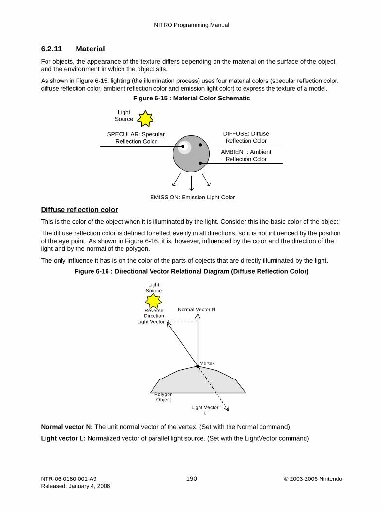
NITRO Programming Manual
6.2.11 MaterialFor objects, the appearance of the texture differs depending on the material on the surface of the object and the environment in which the object sits.
As shown in Figure 6-15, lighting (the illumination process) uses four material colors (specular reflection color, diffuse reflection color, ambient reflection color and emission light color) to express the texture of a model.
Figure 6-15 : Material Color Schematic
Diffuse reflection colorThis is the color of the object when it is illuminated by the light. Consider this the basic color of the object.
The diffuse reflection color is defined to reflect evenly in all directions, so it is not influenced by the position of the eye point. As shown in Figure 6-16, it is, however, influenced by the color and the direction of the light and by the normal of the polygon.
The only influence it has is on the color of the parts of objects that are directly illuminated by the light.
Figure 6-16 : Directional Vector Relational Diagram (Diffuse Reflection Color)
Normal vector N: The unit normal vector of the vertex. (Set with the Normal command)
Light vector L: Normalized vector of parallel light source. (Set with the LightVector command)
AMBIENT: Ambient Reflection Color
DIFFUSE: Diffuse Reflection Color
SPECULAR: Specular Reflection Color
Light Source
EMISSION: Emission Light Color
Reverse Direction
Light Vector -L
Vertex
Polygon Object
Normal Vector N
Light Vector L
Light Source
NTR-06-0180-001-A9 190 © 2003-2006 NintendoReleased: January 4, 2006

NITRO Programming Manual
Ambient reflection colorThis is the color of the object when it is illuminated by ambient light.
Objects are illuminated not only by direct light, but also by light reflecting off of other objects.
This reflected light is called ambient light when it is defined to exist uniformly in the entire scene. Since ambient light exists uniformly in the entire scene, it influences the color of the entire object.
Diffuse reflection color has strong influence of parts of the object that are illuminated by direct light, but ambient reflection color has the predominant influence on parts that are shaded.
Specular reflection colorThis is the glossy color of the object when it is illuminated by light. This glossiness is called specular highlight.
In optical terms, specular highlight is the reflected light of the light source. Accordingly, the part of the object where light strikes and reflects straight back to the eye point is the brightest.
Specular highlight is influenced by the color and direction of light, the normal of the polygon and the position of the eye point. (See Figure 6-17.)
When the eye point shifts the specular highlight moves.
It only has influence on the color of the parts of objects that are directly illuminated by the light, and this influence corresponds to the eye point.
Figure 6-17 : Directional Vector Relational Diagram (Specular Reflection Color)
Normal vector N: The unit normal vector for the vertex. (Set with the Normal command.)
Line-of-sight vector E: Normalized vector from eye point toward vertex. Taken to be the same as the negative direction of the z axis in the View coordinate system.
Light vector L: Normalized vector of parallel light source. (Set with the LightVector command.)
Half-angle vector H of L and E: Normalized vector of the sum of the line-of-sight vector and the light vector.
When NITRO performs the calculation for specular reflection shininess, the line-of-sight vector is taken to be the same as the negative direction of the z axis in the View coordinate system, and it is assumed that both the light vector and the normal vector will be transformed into the View coordinate system.
Light Vector L
Line-of-Sight Vector E
Half-Angle Vector H of L and E
Normal Vector N
Reverse DirectionHalf-Angle Vector -H
Polygon Object
Light Source
EyePointVertex
© 2003-2006 Nintendo 191 NTR-06-0180-001-A9Released: January 4, 2006

NITRO Programming Manual
For this reason, when the View matrix (the LookAt matrix) is applied to the projection matrix, the coordinate system for the light vector and normal vector differ from the coordinate system for the line-of-sight vector after the transformation, and the specular reflection result is abnormal.
Accordingly, when the specular reflection color is set to any value other than black (0), the Matrix mode must be set to the Position & Vector Simultaneous Set mode, and the rotation component of the view matrix (the LookAt matrix) must be reflected on the directional vector matrix.
When the specular reflection color is set to black, the view matrix can be applied to the projection matrix because diffusion reflection does not depend on the eye point. In short, you can set the model matrix for the position coordinates matrix, and the combination of the view matrix and the projection matrix for the projection matrix.
Emission light colorThis is the color of the light that is emitted from the object itself.
Note that this is not treated as light, so it does not illuminate other objects (i.e., it does not influence the color of other objects).
To achieve this result, you need to create a light source that is the same color as the emission light color and place it at the same position as the object that you want emitting light.
MaterialColor0: Set the Material's Diffuse Reflection Color and Ambient Reflection ColorName: DIF_AMB Address: 0x040004C0 Attribute: W Command Code: 0x30
• C[d15]: Vertex color set flag
If diffuse reflection color has been set for the vertex color, it remains valid until the next time the Color, Normal or MaterialColor0 (vertex color set flag) command is issued and the current vertex color is updated.
Because the vertex color is handled as bits R:G:B = 6:6:6 in the Rendering Engine, the diffuse reflection color is applied to the upper five bits. When diffuse reflection color is 0, the lower 1 bit is 0, and when the diffuse reflection color is nonzero, the lower 1 bit is 1.
MaterialColor1: Set the Material's Specular Reflection Color and Emission ColorName: SPE_EMI Address: 0x040004C4 Attribute: W Command Code: 0x31
• S[d15] : Specular reflection shininess table - enable flag
0 Does not set vertex color
1 Sets the diffuse reflection color as the vertex color
0 Disable
1 Enable
AMBIENT_BLUE AMBIENT_GREEN AMBIENT_RED C DIFFUSE_BLUE DIFFUSE_GREEN DIFFUSE_REDAmbient reflection color Diffuse reflection color
31 30 26 25 24 23 21 20 16 15 14 10 9 8 7 5 4 0
Vertex
EMISSION_BLUE EMISSION_GREEN EMISSION_RED S SPECULAR_BLUE SPECULAR_GREEN SPECULAR_REDEmission color Specular reflection color
31 30 26 25 24 23 21 20 16 15 14 10 9 8 7 5 4 0
Shininess
NTR-06-0180-001-A9 192 © 2003-2006 NintendoReleased: January 4, 2006
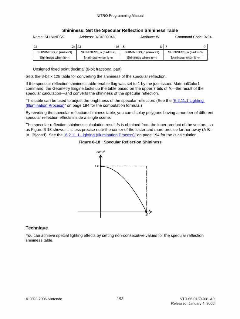
NITRO Programming Manual
Shininess: Set the Specular Reflection Shininess TableName: SHININESS Address: 0x0400004D Attribute: W Command Code: 0x34
Unsigned fixed point decimal (8-bit fractional part)
Sets the 8-bit x 128 table for converting the shininess of the specular reflection.
If the specular reflection shininess table-enable flag was set to 1 by the just-issued MaterialColor1 command, the Geometry Engine looks up the table based on the upper 7 bits of Is—the result of the specular calculation—and converts the shininess of the specular reflection.
This table can be used to adjust the brightness of the specular reflection. (See the "6.2.11.1 Lighting (Illumination Process)" on page 194 for the computation formula.)
By rewriting the specular reflection shininess table, you can display polygons having a number of different specular reflection effects inside a single scene.
The specular reflection shininess calculation result Is is obtained from the inner product of the vectors, so as Figure 6-18 shows, it is less precise near the center of the luster and more precise farther away (A·B = |A| |B|cosθ). See the "6.2.11.1 Lighting (Illumination Process)" on page 194 for the Is calculation.
Figure 6-18 : Specular Reflection Shininess
TechniqueYou can achieve special lighting effects by setting non-consecutive values for the specular reflection shininess table.
SHININESS_n (n=4x+3) SHININESS_n (n=4x+2) SHININESS_n (n=4x+1) SHININESS_n (n=4x+0)Shininess when ls=n Shininess when ls=n Shininess when ls=n Shininess when ls=n
31 24 23 16 15 8 7 0
θ
cosθ
1.0
© 2003-2006 Nintendo 193 NTR-06-0180-001-A9Released: January 4, 2006

NITRO Programming Manual
6.2.11.1 Lighting (Illumination Process)Lighting (the illumination process) is conducted when the Normal command is issued, and the results of the calculations are used for the vertex color.
The computations shown below are done on each color component (R, G, B).
Lighting Formulas for the Various Material Colors
L : The light's directional vector
N : Normal vector
H : The vector that is half the sum of L (the light's directional vector) and the line-of-sight vector (the vector that points in the negative direction of the Z axis.) This is called a half-angle vector because it indicates the direction halfway between the L and line-of-sight vectors.
θ : The angle between the vector (-H) and the vector (N)
ld : Diffuse reflection shininess
ls : Specular reflection shininess
light : Light color
diffuse_material : Material's diffuse reflection color
ambient_material : Material's ambient reflection color
specular_material : Material's specular reflection color
emission_material : Material's emission color
Material Color Lighting Formulas
Diffuse Reflection Color ld = max[ 0, –L•N ]D = ld*light*diffuse_material
Ambient Reflection Color A = light*ambient_material
Specular Reflection Color
ls = max[ 0, cos 2 θ]
(When the specular reflection shininess table is disabled)S = ls*light*specular_material
(When the specular reflection shininess table is enabled)S = shininess_table[ ls ]*light*specular_material
Emission Color E = emission_material
NTR-06-0180-001-A9 194 © 2003-2006 NintendoReleased: January 4, 2006
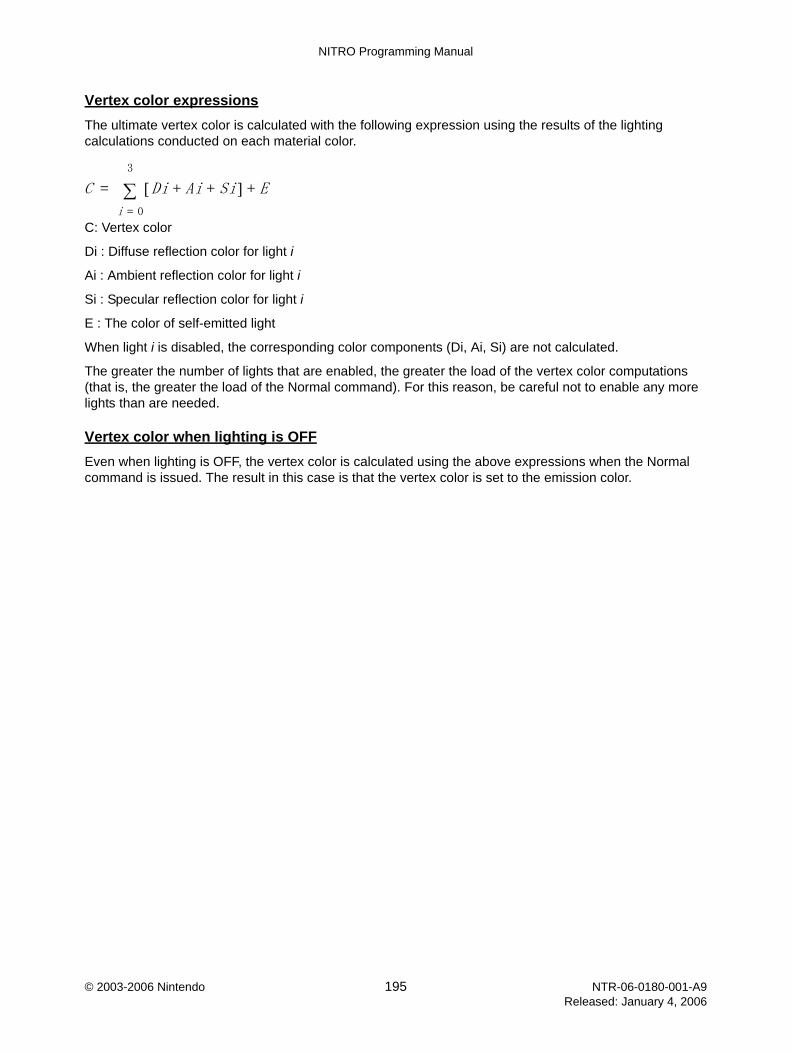
NITRO Programming Manual
Vertex color expressionsThe ultimate vertex color is calculated with the following expression using the results of the lighting calculations conducted on each material color.
C: Vertex color
Di : Diffuse reflection color for light i
Ai : Ambient reflection color for light i
Si : Specular reflection color for light i
E : The color of self-emitted light
When light i is disabled, the corresponding color components (Di, Ai, Si) are not calculated.
The greater the number of lights that are enabled, the greater the load of the vertex color computations (that is, the greater the load of the Normal command). For this reason, be careful not to enable any more lights than are needed.
Vertex color when lighting is OFFEven when lighting is OFF, the vertex color is calculated using the above expressions when the Normal command is issued. The result in this case is that the vertex color is set to the emission color.
C Di Ai Si+ +[ ] E+i 0=
3
∑=
© 2003-2006 Nintendo 195 NTR-06-0180-001-A9Released: January 4, 2006

NITRO Programming Manual
6.2.12 Polygon Attributes
PolygonAttr: Set the Polygon-Related Attribute ValuesName: POLYGON_ATTR Address: 0x040004A4 Attribute: W Command Code: 0x29
• [d29–d24] : Polygon ID
The polygon ID is stored in separate attribute buffers for opaque polygons and translucent polygons when the polygon is being rendered by the Rendering Engine. The stored polygon ID is used when rendering translucent polygons and shadow polygons and when edge-marking. For details, see "6.3.4 Rasterizing" on page 233.
• [d20–d16] : alpha value
The polygon is called a translucent polygon when 1 ≤ α ≤ 30 and an opaque polygon when α = 31. When α = 0, the display becomes a wireframe display and the original meaning of α is lost.
• FE[d15] : Fog-enable flag
When fog is enabled, the Rendering Engine performs fog blending.
To learn about fog blending, see "6.3.9 Fog Blending" on page 258.
• DT[d14] : Depth test conditions
When set to 1, another polygon can be pasted on a polygon that has already been rendered (decal polygon).
1–31 Polygon's opaqueness
0 Wire frame display
0 Disable
1 Enable
0 Rendering when the fragment's depth value is smaller than the depth buffer's depth value.
1 Rendering when the fragment's depth value is equal to the depth buffer's depth value.
FE DT D1 FC XL FR BK L3 L2 L1 L0Polygon ID Alpha Value
31 29 24 23 20 16 15 14 13 12 11 8 7 6 5 4 3 0
Fog Enable Flag
Depth Test Conditions
FAR Plane Intersecting Polygon Display Specification
Translucent Polygon Depth Value Update - Enable Flag
Polygon Rendering Screen
Polygon Mode
Light Enable Flags
NTR-06-0180-001-A9 196 © 2003-2006 NintendoReleased: January 4, 2006
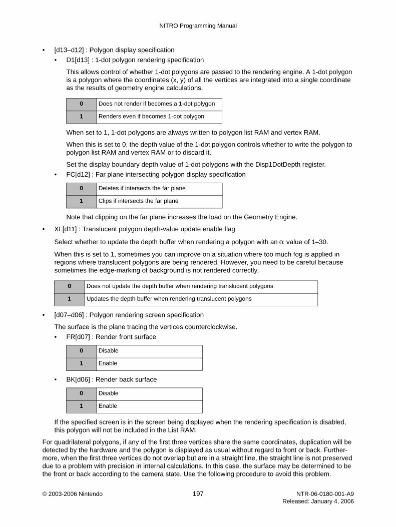
NITRO Programming Manual
• [d13–d12] : Polygon display specification• D1[d13] : 1-dot polygon rendering specification
This allows control of whether 1-dot polygons are passed to the rendering engine. A 1-dot polygon is a polygon where the coordinates (x, y) of all the vertices are integrated into a single coordinate as the results of geometry engine calculations.
When set to 1, 1-dot polygons are always written to polygon list RAM and vertex RAM.
When this is set to 0, the depth value of the 1-dot polygon controls whether to write the polygon to polygon list RAM and vertex RAM or to discard it.
Set the display boundary depth value of 1-dot polygons with the Disp1DotDepth register.• FC[d12] : Far plane intersecting polygon display specification
Note that clipping on the far plane increases the load on the Geometry Engine.
• XL[d11] : Translucent polygon depth-value update enable flag
Select whether to update the depth buffer when rendering a polygon with an α value of 1–30.
When this is set to 1, sometimes you can improve on a situation where too much fog is applied in regions where translucent polygons are being rendered. However, you need to be careful because sometimes the edge-marking of background is not rendered correctly.
• [d07–d06] : Polygon rendering screen specification
The surface is the plane tracing the vertices counterclockwise.• FR[d07] : Render front surface
• BK[d06] : Render back surface
If the specified screen is in the screen being displayed when the rendering specification is disabled, this polygon will not be included in the List RAM.
For quadrilateral polygons, if any of the first three vertices share the same coordinates, duplication will be detected by the hardware and the polygon is displayed as usual without regard to front or back. Further-more, when the first three vertices do not overlap but are in a straight line, the straight line is not preserved due to a problem with precision in internal calculations. In this case, the surface may be determined to be the front or back according to the camera state. Use the following procedure to avoid this problem.
0 Does not render if becomes a 1-dot polygon
1 Renders even if becomes 1-dot polygon
0 Deletes if intersects the far plane
1 Clips if intersects the far plane
0 Does not update the depth buffer when rendering translucent polygons
1 Updates the depth buffer when rendering translucent polygons
0 Disable
1 Enable
0 Disable
1 Enable
© 2003-2006 Nintendo 197 NTR-06-0180-001-A9Released: January 4, 2006

NITRO Programming Manual
• Change the order the vertices are sent• Have the second coordinate value be the same as the first or third coordinate value (Of the first
three vertices, set 1 and 2 or 2 and 3 to the same value)• Separate into triangles
When rendering a line segment in which polygon vertex coordinates overlap, front/back determination is impossible, and therefore it is always rendered, regardless of this flag’s setting.
• PM[d05–d04] : Polygon mode
Modulation mode and decal mode are ways of blending texture color and fragment color.
Toon / Highlight shading is a way to transform with the fragment color table.
Shadow polygon is a feature for applying shadow using the stencil buffer.
For details, see the respective parts in the Rendering Engine "6.3.1 Overview" on page 224.
About Toon/Highlight ShadingToon and Highlight Shading share use of the same table.
Use the DISP3DCN register to choose either Toon or Highlight.
The setting written to the DISP3DCN register becomes valid when the frame switches, so Toon and Highlight Shading cannot be mixed in the same drawing frame.
• L3–L0[d03–d00] : Light enable flags
These are separate flags for setting lights 0–3.
00 Modulation mode
01 Decal mode
10 Toon / Highlight shading
11 Shadow polygon
0 Disable (light off)
1 Enable (light on)
NTR-06-0180-001-A9 198 © 2003-2006 NintendoReleased: January 4, 2006

NITRO Programming Manual
Where to issue the PolygonAttr commandThe values set with the PolygonAttr command become valid when the Begin command is issued. The values are subsequently used as vertex attributes.
Do not issue the PolygonAttr command between the Begin command and the End command.
Simply setting the light enable flag to enabled in the Begin command does not affect the vertex color.
The vertex color is first affected when lighting (lighting process) is performed with the Normal command after the light enable flag setting is enabled in the Begin command.
Disp1DotDepth: 1-Dot Polygon Display Boundary Depth Value RegisterName: DISP_1DOT_DEptH Address: 0x04000610 Attribute: W Initial value: 0x7FFF
Fixed-point number (12-bit integer + 3-bit fractional part)
• W coordinates [d14–d00] : Depth value
When the PolygonAttr command’s “1-dot polygon rendering specification flag” is 0, the Geometry Engine references this register for use as described below:
When the X and Y coordinates of all polygon vertices are transformed into BG screen coordinates within a range of 1 dot or less, if the smallest W value (the depth value) is larger than this register’s setting value, polygon data is not written to Polygon List RAM or Vertex RAM (and is not displayed as a result).
This W value is referenced even during Z buffering.
INTEGER_W DECIMAL_WW Coordinate
15 14 8 7 0
© 2003-2006 Nintendo 199 NTR-06-0180-001-A9Released: January 4, 2006

NITRO Programming Manual
6.2.13 PolygonsBEGIN_VTXS: Declare the Start of the Vertex List
Name: BEGIN_VTXS Address: 0x04000500 Attribute: W Command Code: 0x40
• TYPE[d01–d00] : Primitive type
Polygon strips share vertices, so they consume less Vertex RAM than independent polygons of the same shape.
The table below shows the relation between drawing and the order in which vertices are issued by the Vertex command for different types of primitives.
Relation between Drawing and the Order in which the Vertex Command Issues Vertices
Defining the primitive's front surfaceThe surface is described counterclockwise (v0, v1, v2,... : in order of issued Vertex-group commands).
Figure 6-19 : Order in which the Vertex commands issues vertices
When you want to draw line segments, set the same value for neighboring vertices in the above primitives. However, because it is not possible to determine the front or back of the line segments, they are always rendered, even if the polygon attributes specify to disable display. As Figure 6-20 shows, the anti-aliasing and edge marking features (see the Rendering Engine "6.3.1 Overview" on page 224) work on line segments as well.
00 Triangle
01 Quadrilateral
10 Triangle Strips
11 Quadrilateral Strips
Triangle Polygon A series of triangles are drawn starting with vertices “v0, v1, and v2” and then vertices “v3, v4, and v5.”
Quadrilateral Polygon A series of quadrilaterals are drawn starting with vertices “v0, v1, v2, and v3” and then vertices “v4, v5, v6, and v7.”
Triangle StripsA series of triangles are draw starting with vertices “v0, v1, and v2,” “v2, v1, and v3” and then “v2, v3, and v4.” This is the order so that the triangles are drawn in the same direction on both sides of the surface. (See Figure 6-15.)
Quadrilateral StripsA series of quadrilaterals are drawn starting with vertices “v0, v1, v3, and v2,” “v2, v3, v5, and v4” and then “v4, v5, v7, and v6.” This is the order so that the quadrilaterals are drawn in the same direction on both sides of the surface. (See Figure 6-15.)
TYPEType
31 24 23 16 15 8 7 01
v0
v1 v2
v3v0
v1 v2 v1
v0
v3
v2
v5
v4
v7
v6
Triangle Triangle Strips Quad Quad Strips
v3
v4
v1
v2
v0
NTR-06-0180-001-A9 200 © 2003-2006 NintendoReleased: January 4, 2006
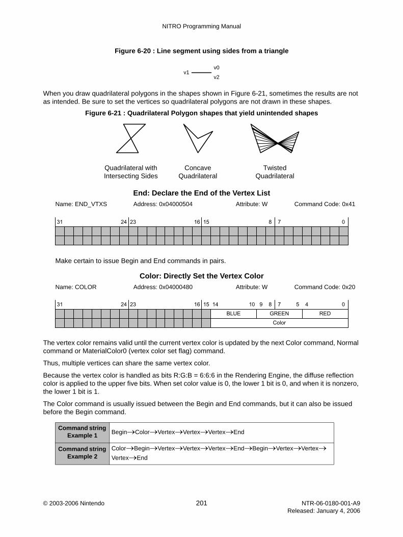
NITRO Programming Manual
Figure 6-20 : Line segment using sides from a triangle
When you draw quadrilateral polygons in the shapes shown in Figure 6-21, sometimes the results are not as intended. Be sure to set the vertices so quadrilateral polygons are not drawn in these shapes.
Figure 6-21 : Quadrilateral Polygon shapes that yield unintended shapes
End: Declare the End of the Vertex ListName: END_VTXS Address: 0x04000504 Attribute: W Command Code: 0x41
Make certain to issue Begin and End commands in pairs.
Color: Directly Set the Vertex ColorName: COLOR Address: 0x04000480 Attribute: W Command Code: 0x20
The vertex color remains valid until the current vertex color is updated by the next Color command, Normal command or MaterialColor0 (vertex color set flag) command.
Thus, multiple vertices can share the same vertex color.
Because the vertex color is handled as bits R:G:B = 6:6:6 in the Rendering Engine, the diffuse reflection color is applied to the upper five bits. When set color value is 0, the lower 1 bit is 0, and when it is nonzero, the lower 1 bit is 1.
The Color command is usually issued between the Begin and End commands, but it can also be issued before the Begin command.
Command string Example 1 Begin→Color→Vertex→Vertex→Vertex→End
Command string Example 2
Color→Begin→Vertex→Vertex→Vertex→End→Begin→Vertex→Vertex→ Vertex→End
v0v1
v2
Quadrilateral with Intersecting Sides
Concave Quadrilateral
Twisted Quadrilateral
31 24 23 16 15 8 7 0
BLUE GREEN REDColor
31 24 23 16 15 14 10 9 8 7 5 4 0
© 2003-2006 Nintendo 201 NTR-06-0180-001-A9Released: January 4, 2006

NITRO Programming Manual
Normal: Set the Normal VectorName: NORMAL Address: 0x04000484 Attribute: W Command Code: 0x21
Signed fixed-point number (sign + 9-bit fractional part)
Lighting (illumination process) is performed only when the Normal command is executed.
Accordingly, you need to reissue the Normal command after you switch lighting On/Of or change the light or material parameters in order for the change to be reflected in the vertex color. (See note.)
Further, the hardware does not normalize vectors, so you need to set the unit vector.
The vertex color obtained with the lighting process remains valid until the current vertex color is updated by the next Color command, Normal command or MaterialColor0 (vertex color set flag) command.
Thus, in actuality multiple vertices can share the same normal vector.
Note: To turn light on or off, after setting in the PolygonAttr command, first enable the set value with the Begin command, and then issue the Normal command.
Where to issue the Normal commandThe Normal command is usually issued between the Begin and End commands, but it can also be issued before the Begin command.
VTX_16: Set the Vertex CoordinatesName: VTX_16 Address: 0x0400048C Attribute: W Command Code: 0x23
Signed fixed-point number (sign + 3-bit integer + 12-bit fractional part)
Command string Example 1 Begin→Normal→Vertex→Vertex→Vertex→End
Command string Example 2
Normal→Begin→Vertex→Vertex→Vertex→End→Begin→Vertex→Vertex→ Vertex→End
S NZ S NY S
Normal vector’s Z component Normal vector’s Y component Normal vector’s X component
31 30 29 28 24 23 20 19 18 16 15 10 9 8 7 0
NX
SY INT_Y DECIMAL_Y SX INT_X DECIMAL_XY Coordinate X Coordinate
31 30 28 27 24 23 16 15 14 12 11 8 7 0
SZ INT_Z DECIMAL_ZZ Coordinate
31 24 23 16 15 14 12 11 8 7 0
NTR-06-0180-001-A9 202 © 2003-2006 NintendoReleased: January 4, 2006
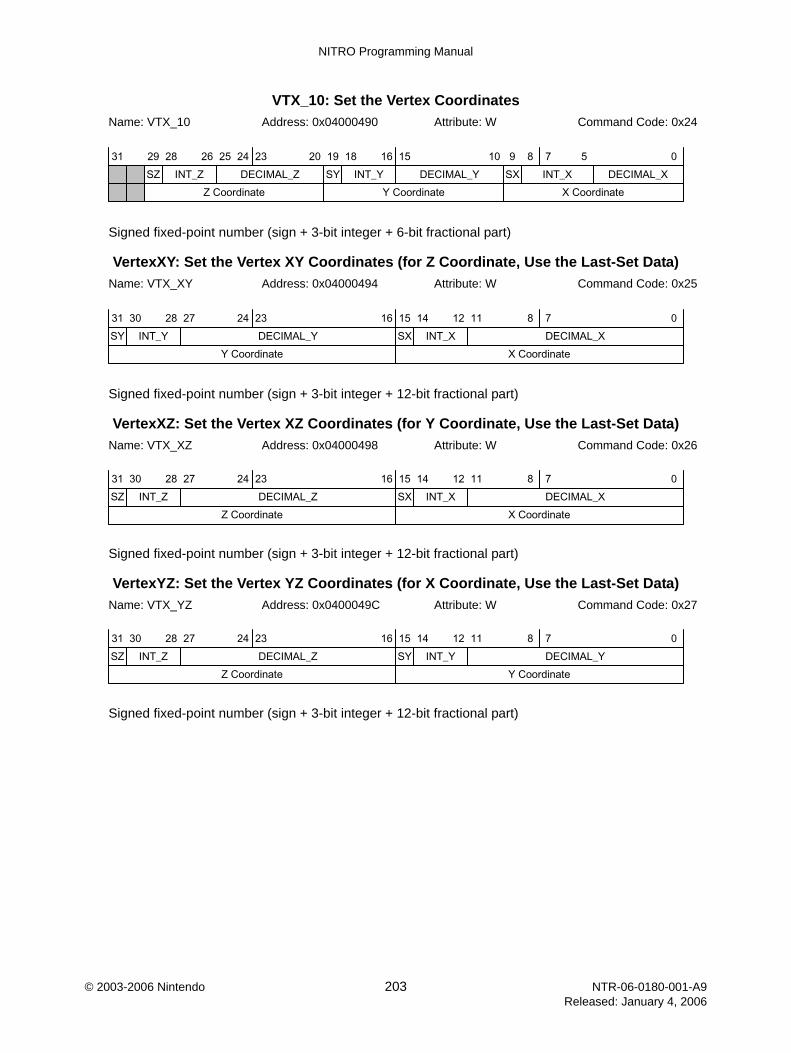
NITRO Programming Manual
VTX_10: Set the Vertex CoordinatesName: VTX_10 Address: 0x04000490 Attribute: W Command Code: 0x24
Signed fixed-point number (sign + 3-bit integer + 6-bit fractional part)
VertexXY: Set the Vertex XY Coordinates (for Z Coordinate, Use the Last-Set Data)Name: VTX_XY Address: 0x04000494 Attribute: W Command Code: 0x25
Signed fixed-point number (sign + 3-bit integer + 12-bit fractional part)
VertexXZ: Set the Vertex XZ Coordinates (for Y Coordinate, Use the Last-Set Data)Name: VTX_XZ Address: 0x04000498 Attribute: W Command Code: 0x26
Signed fixed-point number (sign + 3-bit integer + 12-bit fractional part)
VertexYZ: Set the Vertex YZ Coordinates (for X Coordinate, Use the Last-Set Data)Name: VTX_YZ Address: 0x0400049C Attribute: W Command Code: 0x27
Signed fixed-point number (sign + 3-bit integer + 12-bit fractional part)
SZ INT_Z DECIMAL_Z SY INT_Y DECIMAL_Y SX INT_X DECIMAL_XZ Coordinate Y Coordinate X Coordinate
31 29 28 26 25 24 23 20 19 18 16 15 10 9 8 7 5 0
SY INT_Y DECIMAL_Y SX INT_X DECIMAL_XY Coordinate X Coordinate
31 30 28 27 24 23 16 15 14 12 11 8 7 0
SZ INT_Z DECIMAL_Z SX INT_X DECIMAL_XZ Coordinate X Coordinate
31 30 28 27 24 23 16 15 14 12 11 8 7 0
SZ INT_Z DECIMAL_Z SY INT_Y DECIMAL_YZ Coordinate Y Coordinate
31 30 28 27 24 23 16 15 14 12 11 8 7 0
© 2003-2006 Nintendo 203 NTR-06-0180-001-A9Released: January 4, 2006

NITRO Programming Manual
VertexDiff: Set the Difference Value of the Last-Set Data for Vertex CoordinatesName: VTX_DIFF Address: 0x040004A0 Attribute: W Command Code: 0x28
Signed fixed-point number (sign + 9-bit fractional part)
The value after adding to the last-set vertex value is stored as the 16-bit vertex coordinates.
The VertexDiff command data is sign-extended to 16 bits and added to the prior-set vertex coordinate. The vertex coordinates (the Vertex-group command's data) are 16 bits in size (sign + 3-bit integer + 12-bit fractional part), so the data of the VertexDiff command corresponds to the 4th to 12th places of the fractional part of the vertex coordinates (see Figure 6-22.)
Note: Use caution because an overflow can occur during the addition process.
Figure 6-22 : The Process for Adding the X Coordinate
Items common to all Vertex commandsWhen Vertex commands are issued, the vertex data that have been transformed into BG screen coordinates are stored in Vertex RAM. Further, polygon data is stored to Polygon List RAM when the data for the number of vertices comprising the polygon are processed.
Note: Be sure to issue Vertex commands between the Begin command and the End command and that there are not too many or too few vertices in the specified primitives.
SZ DECIMAL_Z SY DECIMAL_Y SX DECIMAL_XZ Coordinate Y Coordinate X Coordinate
31 29 28 24 23 20 19 18 16 15 10 9 8 7 0
SX
15
INT_X DECIMAL_X
14 12 11 8 7 0
SX
15
SX SX SX SX SX SX DECIMAL_X
9 8 7 0
SX DECIMAL_X
9 8 7 0
Expanded to 16 bits
Last-set vertex coordinates
Addition
VertexDiff command data
NTR-06-0180-001-A9 204 © 2003-2006 NintendoReleased: January 4, 2006
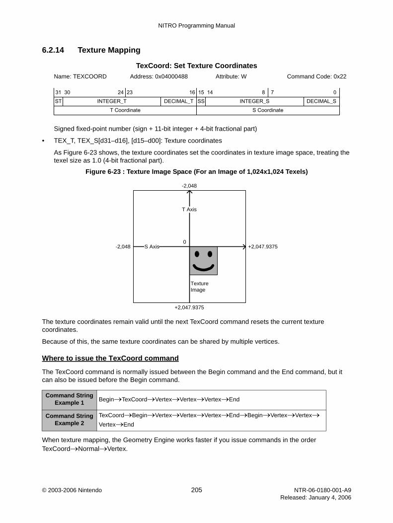
NITRO Programming Manual
6.2.14 Texture Mapping
TexCoord: Set Texture CoordinatesName: TEXCOORD Address: 0x04000488 Attribute: W Command Code: 0x22
Signed fixed-point number (sign + 11-bit integer + 4-bit fractional part)
• TEX_T, TEX_S[d31–d16], [d15–d00]: Texture coordinates
As Figure 6-23 shows, the texture coordinates set the coordinates in texture image space, treating the texel size as 1.0 (4-bit fractional part).
Figure 6-23 : Texture Image Space (For an Image of 1,024x1,024 Texels)
The texture coordinates remain valid until the next TexCoord command resets the current texture coordinates.
Because of this, the same texture coordinates can be shared by multiple vertices.
Where to issue the TexCoord command
The TexCoord command is normally issued between the Begin command and the End command, but it can also be issued before the Begin command.
When texture mapping, the Geometry Engine works faster if you issue commands in the order TexCoord→Normal→Vertex.
Command String Example 1 Begin→TexCoord→Vertex→Vertex→Vertex→End
Command String Example 2
TexCoord→Begin→Vertex→Vertex→Vertex→End→Begin→Vertex→Vertex→ Vertex→End
ST INTEGER_T DECIMAL_T SS INTEGER_S DECIMAL_ST Coordinate S Coordinate
31 30 24 23 16 15 14 8 7 0
0+2,047.9375
-2,048
+2,047.9375
-2,048 S Axis
T Axis
Texture Image
© 2003-2006 Nintendo 205 NTR-06-0180-001-A9Released: January 4, 2006

NITRO Programming Manual
TexImageParam: Setting the Texture ParametersName: TEXIMAGE_PARAM Address: 0x040004A8 Attribute: W Command Code: 0x2a
• TGEN[d31–d30] : Texture coordinates transformation mode
• TR[d29] : Enable flag for the palette's color0 transparency
When using transparent texels with 4-, 16-, 256-color palette textures, set this bit to “1” so the palette's color0 can be referenced for the transparent color.
• TEXFMT[d28–d26] : Texture format
00 Do not transform texture coordinates
01 TexCoord source
10 Normal source
11 Vertex source
0 Enable the palette's color0 setting
1 Make appear transparent, regardless of the palette color0 setting value
0 No texture
1 A3I5 translucent texture
2 4-color palette texture
3 16-color palette texture
4 256-color palette texture
5 4x4 texel compressed texture
6 A5I3 translucent texture
7 Direct texture
T_SIZE S_SIZE FT FS RT RS
Texture Size Texture's Starting Address in VRAM
31 30 29 28 26 25 24 23 20 19 18 17 16 15 8 7 0
Texture Coordinates Transformation Mode
Enable Flag for Palette Color 0 Transparency
Texture FormatFlip Repeat
NTR-06-0180-001-A9 206 © 2003-2006 NintendoReleased: January 4, 2006
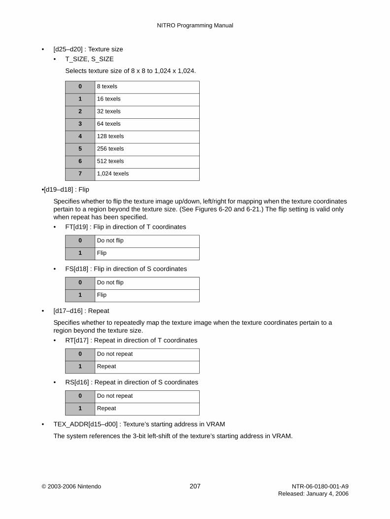
NITRO Programming Manual
• [d25–d20] : Texture size• T_SIZE, S_SIZE
Selects texture size of 8 x 8 to 1,024 x 1,024.
•[d19–d18] : Flip
Specifies whether to flip the texture image up/down, left/right for mapping when the texture coordinates pertain to a region beyond the texture size. (See Figures 6-20 and 6-21.) The flip setting is valid only when repeat has been specified.• FT[d19] : Flip in direction of T coordinates
• FS[d18] : Flip in direction of S coordinates
• [d17–d16] : Repeat
Specifies whether to repeatedly map the texture image when the texture coordinates pertain to a region beyond the texture size.• RT[d17] : Repeat in direction of T coordinates
• RS[d16] : Repeat in direction of S coordinates
• TEX_ADDR[d15–d00] : Texture’s starting address in VRAM
The system references the 3-bit left-shift of the texture’s starting address in VRAM.
0 8 texels
1 16 texels
2 32 texels
3 64 texels
4 128 texels
5 256 texels
6 512 texels
7 1,024 texels
0 Do not flip
1 Flip
0 Do not flip
1 Flip
0 Do not repeat
1 Repeat
0 Do not repeat
1 Repeat
© 2003-2006 Nintendo 207 NTR-06-0180-001-A9Released: January 4, 2006
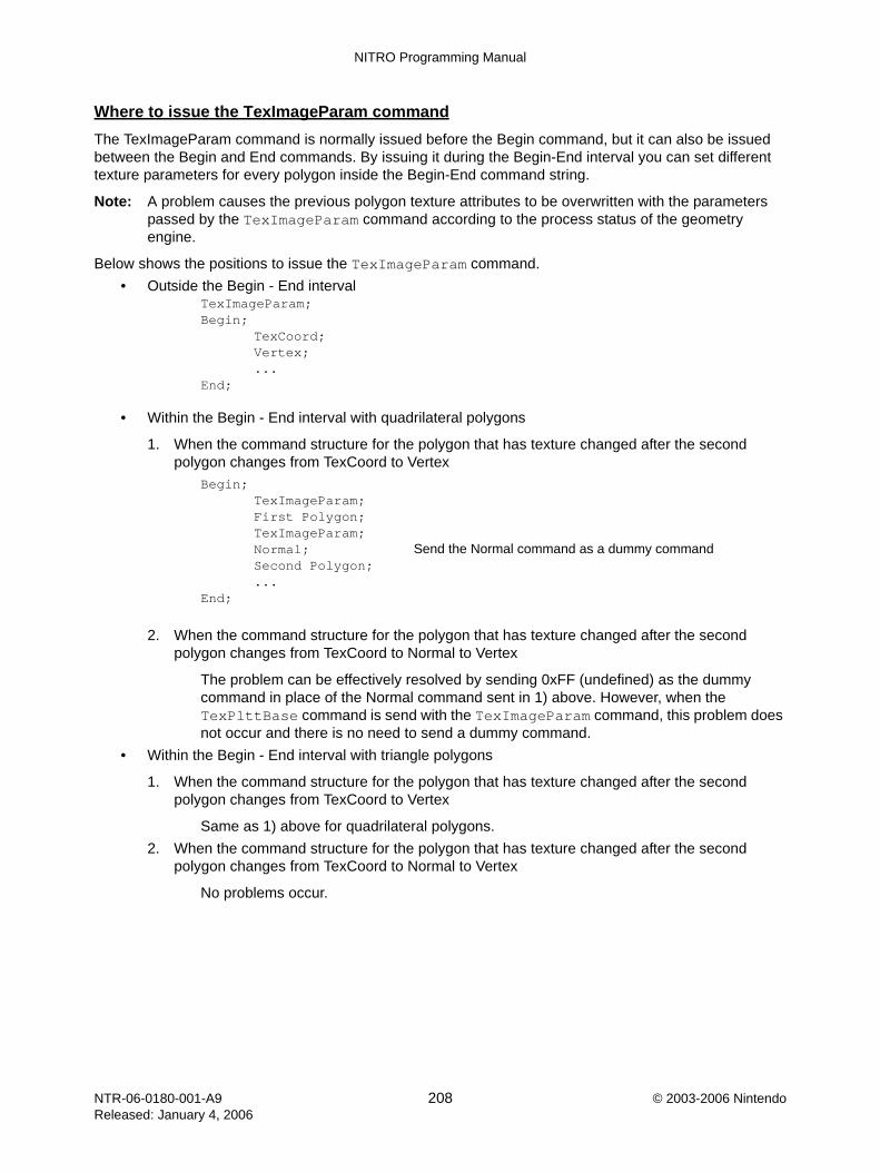
NITRO Programming Manual
Where to issue the TexImageParam commandThe TexImageParam command is normally issued before the Begin command, but it can also be issued between the Begin and End commands. By issuing it during the Begin-End interval you can set different texture parameters for every polygon inside the Begin-End command string.
Note: A problem causes the previous polygon texture attributes to be overwritten with the parameters passed by the TexImageParam command according to the process status of the geometry engine.
Below shows the positions to issue the TexImageParam command.• Outside the Begin - End interval
TexImageParam;Begin;
TexCoord;Vertex;...
End;
• Within the Begin - End interval with quadrilateral polygons
1. When the command structure for the polygon that has texture changed after the second polygon changes from TexCoord to Vertex
Begin;TexImageParam;First Polygon;TexImageParam;Normal; Send the Normal command as a dummy commandSecond Polygon;...
End;
2. When the command structure for the polygon that has texture changed after the second polygon changes from TexCoord to Normal to Vertex
The problem can be effectively resolved by sending 0xFF (undefined) as the dummy command in place of the Normal command sent in 1) above. However, when the TexPlttBase command is send with the TexImageParam command, this problem does not occur and there is no need to send a dummy command.
• Within the Begin - End interval with triangle polygons
1. When the command structure for the polygon that has texture changed after the second polygon changes from TexCoord to Vertex
Same as 1) above for quadrilateral polygons.2. When the command structure for the polygon that has texture changed after the second
polygon changes from TexCoord to Normal to Vertex
No problems occur.
NTR-06-0180-001-A9 208 © 2003-2006 NintendoReleased: January 4, 2006
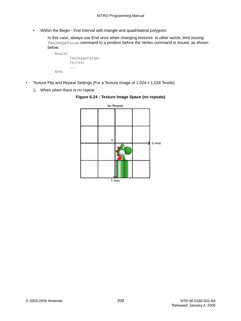
NITRO Programming Manual
• Within the Begin - End interval with triangle and quadrilateral polygons
In this case, always use End once when changing textures. In other words, limit issuing TexImageParam command to a position before the Vertex command is issued, as shown below.
Begin;TexImageParam;Vertex;...
End;
• Texture Flip and Repeat Settings (For a Texture Image of 1,024 x 1,024 Texels)
1. When when there is no repeat
Figure 6-24 : Texture Image Space (no repeats)
0
No Repeat
S-Axis
T-Axis
© 2003-2006 Nintendo 209 NTR-06-0180-001-A9Released: January 4, 2006

NITRO Programming Manual
2. Flip settings when there is a repeat
Figure 6-25 : Texture Image Space (with Repeats)
0
No Flip
S-Axis
T-Axis
0
Flip in S-Coordinate Direction
0
Flip in T-Coordinate Direction
0
Flip in S- and T-Coordinate Directions
S-Axis
S-Axis S-Axis
T-Axis
T-Axis T-Axis
NTR-06-0180-001-A9 210 © 2003-2006 NintendoReleased: January 4, 2006
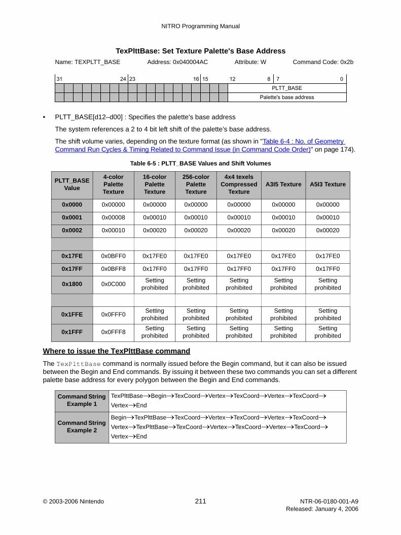
NITRO Programming Manual
TexPlttBase: Set Texture Palette's Base AddressName: TEXPLTT_BASE Address: 0x040004AC Attribute: W Command Code: 0x2b
• PLTT_BASE[d12–d00] : Specifies the palette's base address
The system references a 2 to 4 bit left shift of the palette’s base address.
The shift volume varies, depending on the texture format (as shown in "Table 6-4 : No. of Geometry Command Run Cycles & Timing Related to Command Issue (in Command Code Order)" on page 174).
Table 6-5 : PLTT_BASE Values and Shift Volumes
Where to issue the TexPlttBase commandThe TexPlttBase command is normally issued before the Begin command, but it can also be issued between the Begin and End commands. By issuing it between these two commands you can set a different palette base address for every polygon between the Begin and End commands.
PLTT_BASE Value
4-color Palette Texture
16-color Palette Texture
256-color Palette Texture
4x4 texels Compressed
TextureA3I5 Texture A5I3 Texture
0x0000 0x00000 0x00000 0x00000 0x00000 0x00000 0x00000
0x0001 0x00008 0x00010 0x00010 0x00010 0x00010 0x00010
0x0002 0x00010 0x00020 0x00020 0x00020 0x00020 0x00020
0x17FE 0x0BFF0 0x17FE0 0x17FE0 0x17FE0 0x17FE0 0x17FE0
0x17FF 0x0BFF8 0x17FF0 0x17FF0 0x17FF0 0x17FF0 0x17FF0
0x1800 0x0C000 Setting prohibited
Setting prohibited
Setting prohibited
Setting prohibited
Setting prohibited
0x1FFE 0x0FFF0 Setting prohibited
Setting prohibited
Setting prohibited
Setting prohibited
Setting prohibited
0x1FFF 0x0FFF8 Setting prohibited
Setting prohibited
Setting prohibited
Setting prohibited
Setting prohibited
Command String Example 1
TexPlttBase→Begin→TexCoord→Vertex→TexCoord→Vertex→TexCoord→ Vertex→End
Command String Example 2
Begin→TexPlttBase→TexCoord→Vertex→TexCoord→Vertex→TexCoord→ Vertex→TexPlttBase→TexCoord→Vertex→TexCoord→Vertex→TexCoord→ Vertex→End
PLTT_BASEPalette's base address
31 24 23 16 15 12 8 7 0
© 2003-2006 Nintendo 211 NTR-06-0180-001-A9Released: January 4, 2006
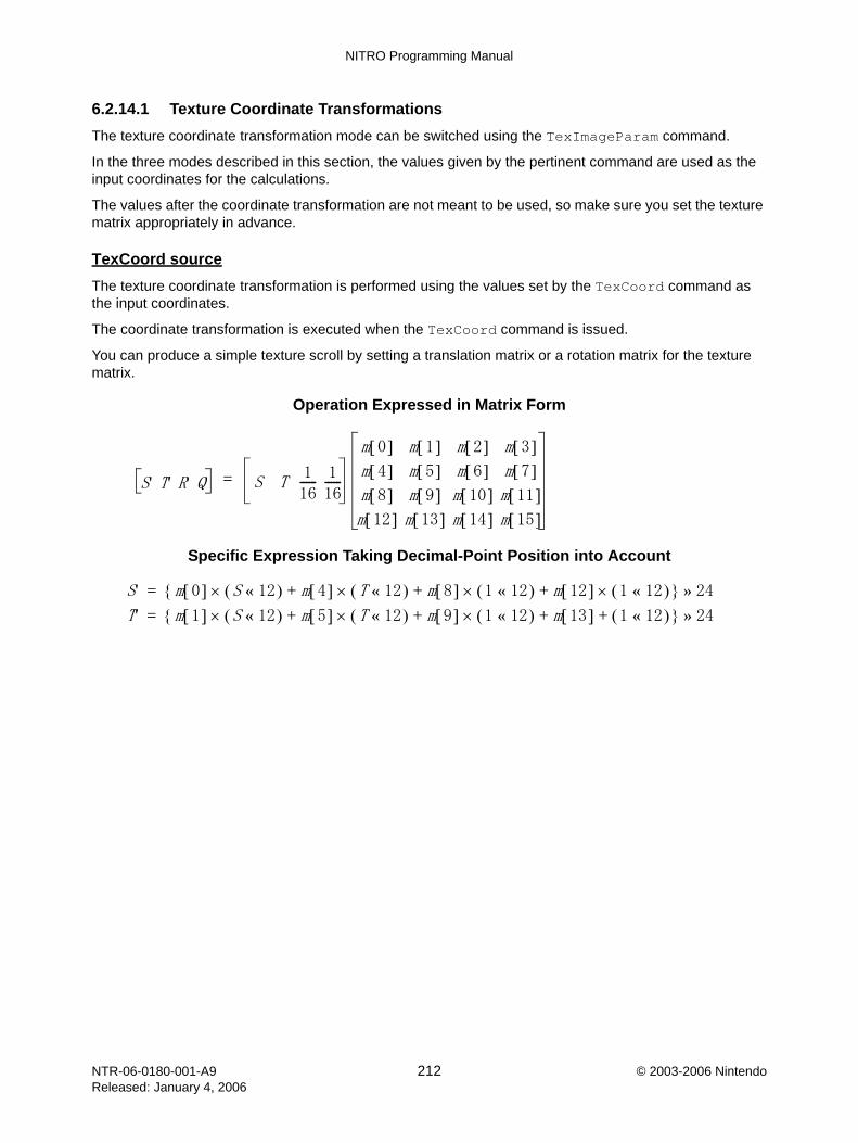
NITRO Programming Manual
6.2.14.1 Texture Coordinate TransformationsThe texture coordinate transformation mode can be switched using the TexImageParam command.
In the three modes described in this section, the values given by the pertinent command are used as the input coordinates for the calculations.
The values after the coordinate transformation are not meant to be used, so make sure you set the texture matrix appropriately in advance.
TexCoord sourceThe texture coordinate transformation is performed using the values set by the TexCoord command as the input coordinates.
The coordinate transformation is executed when the TexCoord command is issued.
You can produce a simple texture scroll by setting a translation matrix or a rotation matrix for the texture matrix.
Operation Expressed in Matrix Form
Specific Expression Taking Decimal-Point Position into Account
S' T' R' Q' S T116------ 1
16------
m 0[ ] m 1[ ] m 2[ ] m 3[ ]m 4[ ] m 5[ ] m 6[ ] m 7[ ]m 8[ ] m 9[ ] m 10[ ] m 11[ ]m 12[ ] m 13[ ] m 14[ ] m 15[ ]
=
S' m 0[ ] S 12«( ) m 4[ ] T 12«( ) m 8[ ] 1 12«( ) m 12[ ] 1 12«( )×+×+×+×{ } 24»=T' m 1[ ] S 12«( ) m 5[ ] T 12«( ) m 9[ ] 1 12«( ) m 13[ ] 1 12«( )+ +×+×+×{ } 24»=
NTR-06-0180-001-A9 212 © 2003-2006 NintendoReleased: January 4, 2006

NITRO Programming Manual
Normal sourceThe texture coordinate transformation is performed using the values set by the Normal command as the input coordinates.
The coordinate transformation is executed when the Normal command is issued.
The S and T values set by the immediately-prior TexCoord command are used as the translation components of the texture coordinates.
You can produce spherical reflection mapping by setting in the texture matrix the result of reading the current directional vector matrix and multiplying by the scaling matrix that expands the directional vector space (-1.0 to 1.0) to 1/2 the texture size. When doing this, use the TexCoord command to translate the origin of the texture coordinate to the center of the spherical texture.
Operation Expressed in Matrix Form
Specific Expression Taking Decimal-Point Position into Account
S' T' R' Q' Nu Nv Nw 1
m 0[ ] m 1[ ] m 2[ ] m 3[ ]m 4[ ] m 5[ ] m 6[ ] m 7[ ]m 8[ ] m 9[ ] m 10[ ] m 11[ ]S T m 14[ ] m 15[ ]
=
S' m 0[ ] Nx 3«( )× m 4[ ] Ny 3«( ) m 8[ ] Nz 3«( ) S 12«( ) 1 12«( )×+×+×+{ } 24»=
T' m 1[ ] Nx 3«( ) m 5[ ] Ny 3«( ) m 9[ ] Nz 3«( )×+×+× T 12«( ) 1 12«( )×+{ } 24»=
© 2003-2006 Nintendo 213 NTR-06-0180-001-A9Released: January 4, 2006
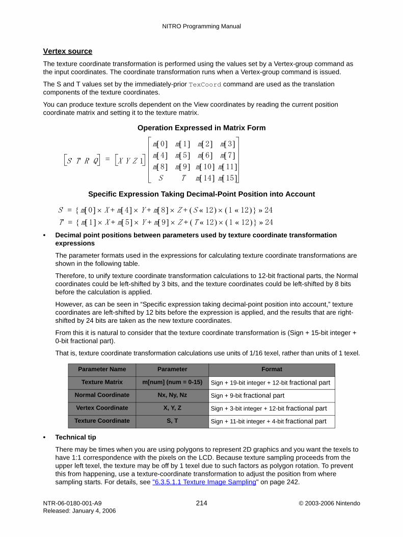
NITRO Programming Manual
Vertex sourceThe texture coordinate transformation is performed using the values set by a Vertex-group command as the input coordinates. The coordinate transformation runs when a Vertex-group command is issued.
The S and T values set by the immediately-prior TexCoord command are used as the translation components of the texture coordinates.
You can produce texture scrolls dependent on the View coordinates by reading the current position coordinate matrix and setting it to the texture matrix.
Operation Expressed in Matrix Form
Specific Expression Taking Decimal-Point Position into Account
• Decimal point positions between parameters used by texture coordinate transformation expressions
The parameter formats used in the expressions for calculating texture coordinate transformations are shown in the following table.
Therefore, to unify texture coordinate transformation calculations to 12-bit fractional parts, the Normal coordinates could be left-shifted by 3 bits, and the texture coordinates could be left-shifted by 8 bits before the calculation is applied.
However, as can be seen in “Specific expression taking decimal-point position into account,” texture coordinates are left-shifted by 12 bits before the expression is applied, and the results that are right-shifted by 24 bits are taken as the new texture coordinates.
From this it is natural to consider that the texture coordinate transformation is (Sign + 15-bit integer + 0-bit fractional part).
That is, texture coordinate transformation calculations use units of 1/16 texel, rather than units of 1 texel.
• Technical tip
There may be times when you are using polygons to represent 2D graphics and you want the texels to have 1:1 correspondence with the pixels on the LCD. Because texture sampling proceeds from the upper left texel, the texture may be off by 1 texel due to such factors as polygon rotation. To prevent this from happening, use a texture-coordinate transformation to adjust the position from where sampling starts. For details, see "6.3.5.1.1 Texture Image Sampling" on page 242.
Parameter Name Parameter Format
Texture Matrix m[num] (num = 0-15) Sign + 19-bit integer + 12-bit fractional part
Normal Coordinate Nx, Ny, Nz Sign + 9-bit fractional part
Vertex Coordinate X, Y, Z Sign + 3-bit integer + 12-bit fractional part
Texture Coordinate S, T Sign + 11-bit integer + 4-bit fractional part
S' T' R' Q' X Y Z 1
m 0[ ] m 1[ ] m 2[ ] m 3[ ]m 4[ ] m 5[ ] m 6[ ] m 7[ ]m 8[ ] m 9[ ] m 10[ ] m 11[ ]S T m 14[ ] m 15[ ]
=
S' m 0[ ] X m 4[ ] Y m 8[ ] Z S 12«( ) 1 12«( )×+×+×+×{ } 24»=T' m 1[ ] X m 5[ ] Y m 9[ ] Z T 12«( ) 1 12«( )×+×+×+×{ } 24»=
NTR-06-0180-001-A9 214 © 2003-2006 NintendoReleased: January 4, 2006
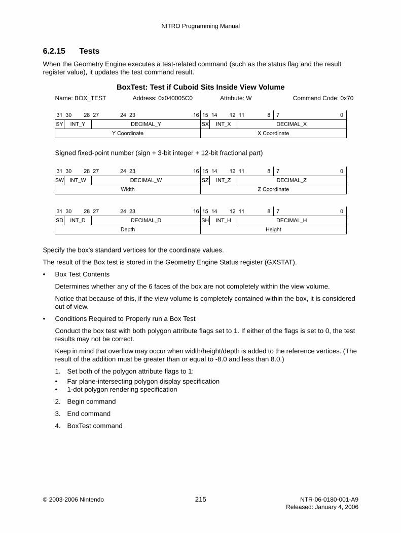
NITRO Programming Manual
6.2.15 TestsWhen the Geometry Engine executes a test-related command (such as the status flag and the result register value), it updates the test command result.
BoxTest: Test if Cuboid Sits Inside View VolumeName: BOX_TEST Address: 0x040005C0 Attribute: W Command Code: 0x70
Signed fixed-point number (sign + 3-bit integer + 12-bit fractional part)
Specify the box's standard vertices for the coordinate values.
The result of the Box test is stored in the Geometry Engine Status register (GXSTAT).
• Box Test Contents
Determines whether any of the 6 faces of the box are not completely within the view volume.
Notice that because of this, if the view volume is completely contained within the box, it is considered out of view.
• Conditions Required to Properly run a Box Test
Conduct the box test with both polygon attribute flags set to 1. If either of the flags is set to 0, the test results may not be correct.
Keep in mind that overflow may occur when width/height/depth is added to the reference vertices. (The result of the addition must be greater than or equal to -8.0 and less than 8.0.)
1. Set both of the polygon attribute flags to 1:• Far plane-intersecting polygon display specification• 1-dot polygon rendering specification
2. Begin command
3. End command
4. BoxTest command
SY INT_Y DECIMAL_Y SX INT_X DECIMAL_XY Coordinate X Coordinate
31 30 28 27 24 23 16 15 14 12 11 8 7 0
SW INT_W DECIMAL_W SZ INT_Z DECIMAL_ZWidth Z Coordinate
31 30 28 27 24 23 16 15 14 12 11 8 7 0
SD INT_D DECIMAL_D SH INT_H DECIMAL_HDepth Height
31 30 28 27 24 23 16 15 14 12 11 8 7 0
© 2003-2006 Nintendo 215 NTR-06-0180-001-A9Released: January 4, 2006
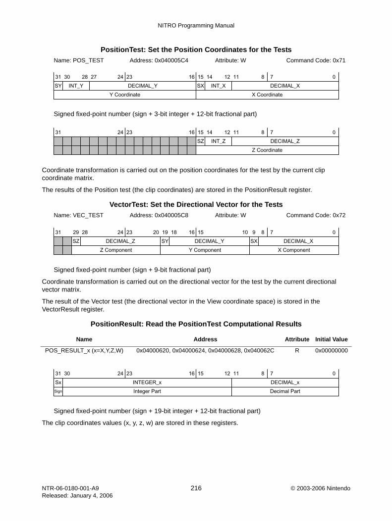
NITRO Programming Manual
PositionTest: Set the Position Coordinates for the TestsName: POS_TEST Address: 0x040005C4 Attribute: W Command Code: 0x71
Signed fixed-point number (sign + 3-bit integer + 12-bit fractional part)
Coordinate transformation is carried out on the position coordinates for the test by the current clip coordinate matrix.
The results of the Position test (the clip coordinates) are stored in the PositionResult register.
VectorTest: Set the Directional Vector for the TestsName: VEC_TEST Address: 0x040005C8 Attribute: W Command Code: 0x72
Signed fixed-point number (sign + 9-bit fractional part)
Coordinate transformation is carried out on the directional vector for the test by the current directional vector matrix.
The result of the Vector test (the directional vector in the View coordinate space) is stored in the VectorResult register.
PositionResult: Read the PositionTest Computational Results
Signed fixed-point number (sign + 19-bit integer + 12-bit fractional part)
The clip coordinates values (x, y, z, w) are stored in these registers.
Name Address Attribute Initial Value
POS_RESULT_x (x=X,Y,Z,W) 0x04000620, 0x04000624, 0x04000628, 0x040062C R 0x00000000
SY INT_Y DECIMAL_Y SX INT_X DECIMAL_XY Coordinate X Coordinate
31 30 28 27 24 23 16 15 14 12 11 8 7 0
SZ INT_Z DECIMAL_ZZ Coordinate
31 24 23 16 15 14 12 11 8 7 0
SZ DECIMAL_Z SY DECIMAL_Y SX DECIMAL_XZ Component Y Component X Component
31 29 28 24 23 20 19 18 16 15 10 9 8 7 0
Sx INTEGER_x DECIMAL_xSign Integer Part Decimal Part
31 30 24 23 16 15 12 11 8 7 0
NTR-06-0180-001-A9 216 © 2003-2006 NintendoReleased: January 4, 2006
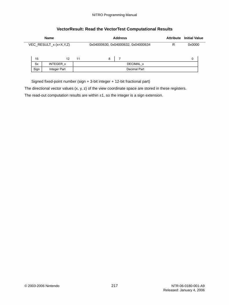
NITRO Programming Manual
VectorResult: Read the VectorTest Computational Results
Signed fixed-point number (sign + 3-bit integer + 12-bit fractional part)
The directional vector values (x, y, z) of the view coordinate space are stored in these registers.
The read-out computation results are within ±1, so the integer is a sign extension.
Name Address Attribute Initial Value
VEC_RESULT_x (x=X,Y,Z) 0x04000630, 0x04000632, 0x04000634 R 0x0000
Sx INTEGER_x DECIMAL_xSign Integer Part Decimal Part
15 8 7 01112
© 2003-2006 Nintendo 217 NTR-06-0180-001-A9Released: January 4, 2006

NITRO Programming Manual
6.2.16 StatusYou can check the status of Polygon List RAM and Vertex RAM using the previously mentioned DISP3DCNT register.
To check the status of command FIFO and matrix stacks, etc., refer to the GXSTAT register below.
GXSTAT: Geometry Engine Status RegisterName: GXSTAT Address: 0x04000600 Attribute: R/W Initial Value: 0x00000000
• FI[d31–d30] : Conditions for Command FIFO interrupt requests
• B[d27] : Geometry Engine busy flag
If commands or parameters have not been sent, the busy flag goes to the command wait / parameter wait status with the busy flag set to 0.
When commands or parameters recommence, geometry processing resumes.
When a SwapBuffers command is issued, and no subsequent commands are issued, the geometry engine busy flag is set to 0 at the completion of a SwapBuffers process, which begins with a V-Blank. (It is 1 until then.)
This timing occurs 400 cycles (calculated at 33 MHz) after the V-Blank.
If, after the SwapBuffers command is issued, a next command is also issued, the next command is executed after the completion of the SwapBuffers process, which commences after the V-Blank.
00 Disable Command FIFO interrupt requests
01 Make interrupt request when Command FIFO is less than half full
10 Make interrupt request when Command FIFO is empty
11 Setting prohibited
0 Geometry Engine is stopped
1 Geometry Engine is running
E H F SE SB PJ PV TR TBCommand FIFO Count Matrix Stack Status
31 30 29 27 26 24 23 16 15 12 8 7 1 0
Conditions for Command FIFO Interrupt Requests
Geometry Engine Busy Flag
Command FIFO Status Test Status
25 14 13
NTR-06-0180-001-A9 218 © 2003-2006 NintendoReleased: January 4, 2006

NITRO Programming Manual
• [d26–d24] : Command FIFO status• E[d26] : Command FIFO empty flag
• H[d25] : Command FIFO under-half flag
• F[d24] : Command FIFO full flag
• [d23–d16] : Command FIFO count value
Can reference the number of commands/amount of data currently stored in Command FIFO.
• [d15–d08] : Matrix stack status• SE[d15] : Stack error flag
The flag is set to 1 when an overflow or underflow of the matrix stack occurs.
It can be cleared by writing 1.
When referencing the status error flag of matrix stack status, confirm that the PushMatrix and PopMatrix commands that have been issued have completed by first referencing the matrix stack busy flag.
• SB[d14] : Matrix stack busy flag• When referencing PJ and PV matrix stack levels, check this flag to confirm that execution of the
issued PushMatrix or PopMatrix command has completed.
• PJ[d13] : Projection matrix stack level
Can reference the current stack level (0–1)• PV[d12–d08] : Position and Vector matrix stack level
Can reference the current stack level (0–31)
0 FIFO is not empty
1 FIFO is empty
0 FIFO is at least half full
1 FIFO is less than half full
0 FIFO is not full
1 FIFO is full
0 No stack overflow or underflow
1 Stack overflow or underflow
0 There is no unexecuted PushMatrix, PopMatrix command
1 The PushMatrix, PopMatrix command has been issued and the execution is not yet completed
© 2003-2006 Nintendo 219 NTR-06-0180-001-A9Released: January 4, 2006
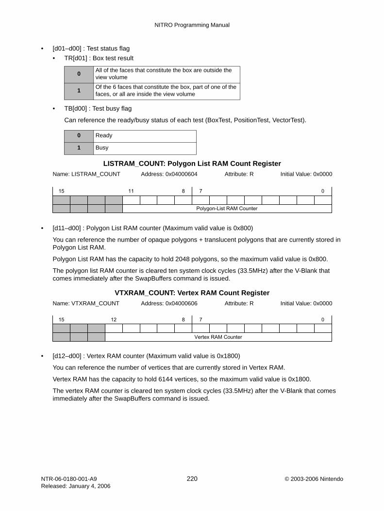
NITRO Programming Manual
• [d01–d00] : Test status flag• TR[d01] : Box test result
• TB[d00] : Test busy flag
Can reference the ready/busy status of each test (BoxTest, PositionTest, VectorTest).
LISTRAM_COUNT: Polygon List RAM Count RegisterName: LISTRAM_COUNT Address: 0x04000604 Attribute: R Initial Value: 0x0000
• [d11–d00] : Polygon List RAM counter (Maximum valid value is 0x800)
You can reference the number of opaque polygons + translucent polygons that are currently stored in Polygon List RAM.
Polygon List RAM has the capacity to hold 2048 polygons, so the maximum valid value is 0x800.
The polygon list RAM counter is cleared ten system clock cycles (33.5MHz) after the V-Blank that comes immediately after the SwapBuffers command is issued.
VTXRAM_COUNT: Vertex RAM Count RegisterName: VTXRAM_COUNT Address: 0x04000606 Attribute: R Initial Value: 0x0000
• [d12–d00] : Vertex RAM counter (Maximum valid value is 0x1800)
You can reference the number of vertices that are currently stored in Vertex RAM.
Vertex RAM has the capacity to hold 6144 vertices, so the maximum valid value is 0x1800.
The vertex RAM counter is cleared ten system clock cycles (33.5MHz) after the V-Blank that comes immediately after the SwapBuffers command is issued.
0 All of the faces that constitute the box are outside the view volume
1 Of the 6 faces that constitute the box, part of one of the faces, or all are inside the view volume
0 Ready
1 Busy
Polygon-List RAM Counter
15 11 8 7 0
Vertex RAM Counter
15 12 8 7 0
NTR-06-0180-001-A9 220 © 2003-2006 NintendoReleased: January 4, 2006
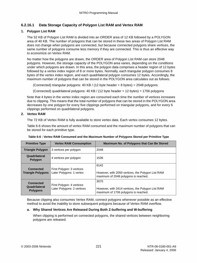
NITRO Programming Manual
6.2.16.1 Data Storage Capacity of Polygon List RAM and Vertex RAM1. Polygon List RAM
The 52 KB of Polygon List RAM is divided into an ORDER area of 12 KB followed by a POLYGON area of 40 KB. The number of polygons that can be stored in these two areas of Polygon List RAM does not change when polygons are connected, but because connected polygons share vertices, the same number of polygons consume less memory if they are connected. This is thus an effective way to economize on Vertex RAM.
No matter how the polygons are drawn, the ORDER area of Polygon List RAM can store 2048 polygons. However, the storage capacity of the POLYGON area varies, depending on the conditions under which polygons are drawn. In this area, the polygon data comprises a header region of 12 bytes followed by a vertex index region of 8 or more bytes. Normally, each triangular polygon consumes 8 bytes of the vertex index region, and each quadrilateral polygon consumes 12 bytes. Accordingly, the maximum number of polygons that can be stored in the POLYGON area calculates out as follows:
(Connected) triangular polygons: 40 KB / (12 byte header + 8 bytes) = 2048 polygons
(Connected) quadrilateral polygons: 40 KB / (12 byte header + 12 bytes) = 1706 polygons
Note that 4 bytes in the vertex index region are consumed each time the number of vertices increases due to clipping. This means that the total number of polygons that can be stored in the POLYGON area decreases by one polygon for every five clippings performed on triangular polygons, and for every 6 clippings performed on quadrilateral polygons.
2. Vertex RAM
The 72 KB of Vertex RAM is fully available to store vertex data. Each vertex consumes 12 bytes.
Table 6-6 shows the amount of vertex RAM consumed and the maximum number of polygons that can be stored for each primitive type.
Table 6-6 : Vertex RAM Consumed and the Maximum Number of Polygons Stored per Primitive Type
Because clipping also consumes Vertex RAM, connect polygons whenever possible as an effective method to avoid the inability to store subsequent polygons because of Vertex RAM overflow.
a. Why Shared Vertices Are Released During Both Z-buffering and W-buffering
When clipping is performed on connected polygons, the shared vertices between neighboring polygons are released.
Primitive Type Vertex RAM Consumption Maximum No. of Polygons that Can Be Stored
Triangle Polygon 3 vertices per polygon 2048
Quadrilateral Polygon 4 vertices per polygon 1536
Connected Triangle Polygons
First Polygon: 3 verticesLater Polygons: 1 vertex
6142
However, with 2050 vertices, the Polygon List RAM maximum of 2048 polygons is reached.
Connected Quadrilateral
Polygons
First Polygon: 4 verticesLater Polygons: 2 vertices
3070
However, with 3414 vertices, the Polygon List RAM maximum of 1706 polygons is reached.
© 2003-2006 Nintendo 221 NTR-06-0180-001-A9Released: January 4, 2006
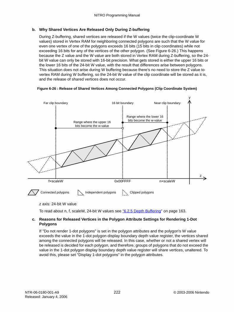
NITRO Programming Manual
b. Why Shared Vertices Are Released Only During Z-buffering
During Z-buffering, shared vertices are released if the W values (twice the clip-coordinate W values) stored in Vertex RAM for neighboring connected polygons are such that the W value for even one vertex of one of the polygons exceeds 16 bits (15 bits in clip coordinates) while not exceeding 16 bits for any of the vertices of the other polygon. (See Figure 6-26.) This happens because the Z value and the W value are both stored in Vertex RAM during Z-buffering, so the 24-bit W value can only be stored with 16-bit precision. What gets stored is either the upper 16 bits or the lower 16 bits of the 24-bit W value, with the result that differences arise between polygons. This situation does not arise during W buffering because there’s no need to store the Z value to vertex RAM during W buffering, so the 24-bit W value of the clip coordinate will be stored as it is, and the release of shared vertices does not occur.
Figure 6-26 : Release of Shared Vertices Among Connected Polygons (Clip Coordinate System)
z axis: 24-bit W value
To read about n, f, scaleW, 24-bit W values see "6.2.5 Depth Buffering" on page 163.
c. Reasons for Released Vertices in the Polygon Attribute Settings for Rendering 1-Dot Polygons
If "Do not render 1-dot polygons" is set in the polygon attributes and the polygon's W value exceeds the value in the 1-dot polygon display boundary depth value register, the vertices shared among the connected polygons will be released. In this case, whether or not a shared vertex will be released is decided for each polygon, and therefore, groups of polygons that do not exceed the value in the 1-dot polygon display boundary depth value register will share vertices, unaltered. To avoid this, please set "Display 1-dot polygons" in the polygon attributes.
n×scaleWf×scaleW 0x00FFFF
y
z
Range where the upper 16 bits become the w-value
Range where the lower 16 bits become the w-value
Far clip boundary Near clip boundary16 bit boundary
Connected polygons Independent polygons Clipped polygons
NTR-06-0180-001-A9 222 © 2003-2006 NintendoReleased: January 4, 2006
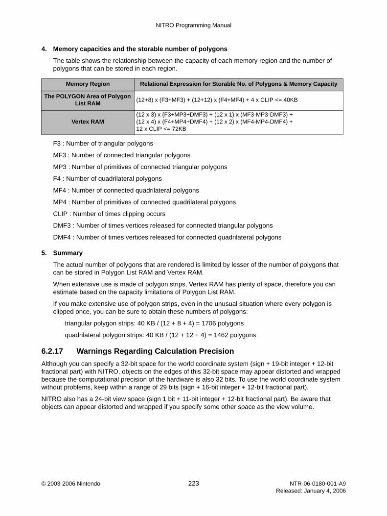
NITRO Programming Manual
4. Memory capacities and the storable number of polygons
The table shows the relationship between the capacity of each memory region and the number of polygons that can be stored in each region.
F3 : Number of triangular polygons
MF3 : Number of connected triangular polygons
MP3 : Number of primitives of connected triangular polygons
F4 : Number of quadrilateral polygons
MF4 : Number of connected quadrilateral polygons
MP4 : Number of primitives of connected quadrilateral polygons
CLIP : Number of times clipping occurs
DMF3 : Number of times vertices released for connected triangular polygons
DMF4 : Number of times vertices released for connected quadrilateral polygons
5. Summary
The actual number of polygons that are rendered is limited by lesser of the number of polygons that can be stored in Polygon List RAM and Vertex RAM.
When extensive use is made of polygon strips, Vertex RAM has plenty of space, therefore you can estimate based on the capacity limitations of Polygon List RAM.
If you make extensive use of polygon strips, even in the unusual situation where every polygon is clipped once, you can be sure to obtain these numbers of polygons:
triangular polygon strips: 40 KB / (12 + 8 + 4) = 1706 polygons
quadrilateral polygon strips: 40 KB / (12 + 12 + 4) = 1462 polygons
6.2.17 Warnings Regarding Calculation PrecisionAlthough you can specify a 32-bit space for the world coordinate system (sign + 19-bit integer + 12-bit fractional part) with NITRO, objects on the edges of this 32-bit space may appear distorted and wrapped because the computational precision of the hardware is also 32 bits. To use the world coordinate system without problems, keep within a range of 29 bits (sign + 16-bit integer + 12-bit fractional part).
NITRO also has a 24-bit view space (sign 1 bit + 11-bit integer + 12-bit fractional part). Be aware that objects can appear distorted and wrapped if you specify some other space as the view volume.
Memory Region Relational Expression for Storable No. of Polygons & Memory Capacity
The POLYGON Area of Polygon List RAM (12+8) x (F3+MF3) + (12+12) x (F4+MF4) + 4 x CLIP <= 40KB
Vertex RAM(12 x 3) x (F3+MP3+DMF3) + (12 x 1) x (MF3-MP3-DMF3) +(12 x 4) x (F4+MP4+DMF4) + (12 x 2) x (MF4-MP4-DMF4) +12 x CLIP <= 72KB
© 2003-2006 Nintendo 223 NTR-06-0180-001-A9Released: January 4, 2006
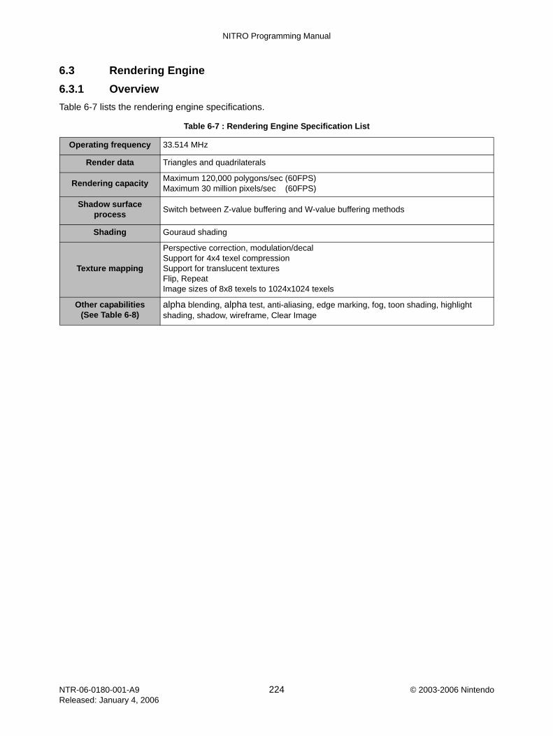
NITRO Programming Manual
6.3 Rendering Engine6.3.1 OverviewTable 6-7 lists the rendering engine specifications.
Table 6-7 : Rendering Engine Specification List
Operating frequency 33.514 MHz
Render data Triangles and quadrilaterals
Rendering capacity Maximum 120,000 polygons/sec (60FPS)Maximum 30 million pixels/sec (60FPS)
Shadow surface process Switch between Z-value buffering and W-value buffering methods
Shading Gouraud shading
Texture mapping
Perspective correction, modulation/decalSupport for 4x4 texel compressionSupport for translucent texturesFlip, RepeatImage sizes of 8x8 texels to 1024x1024 texels
Other capabilities(See Table 6-8)
alpha blending, alpha test, anti-aliasing, edge marking, fog, toon shading, highlight shading, shadow, wireframe, Clear Image
NTR-06-0180-001-A9 224 © 2003-2006 NintendoReleased: January 4, 2006
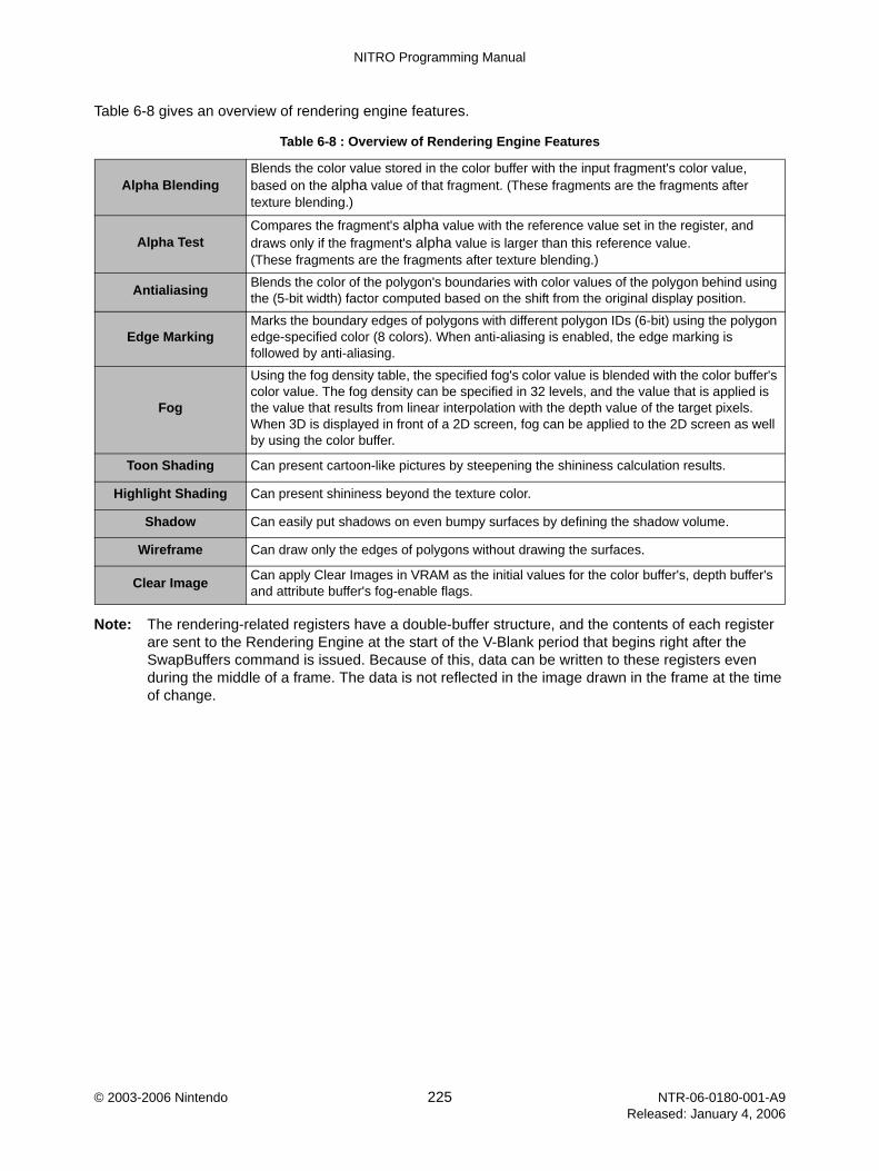
NITRO Programming Manual
Table 6-8 gives an overview of rendering engine features.
Table 6-8 : Overview of Rendering Engine Features
Note: The rendering-related registers have a double-buffer structure, and the contents of each register are sent to the Rendering Engine at the start of the V-Blank period that begins right after the SwapBuffers command is issued. Because of this, data can be written to these registers even during the middle of a frame. The data is not reflected in the image drawn in the frame at the time of change.
Alpha BlendingBlends the color value stored in the color buffer with the input fragment's color value, based on the alpha value of that fragment. (These fragments are the fragments after texture blending.)
Alpha TestCompares the fragment's alpha value with the reference value set in the register, and draws only if the fragment's alpha value is larger than this reference value.(These fragments are the fragments after texture blending.)
Antialiasing Blends the color of the polygon's boundaries with color values of the polygon behind using the (5-bit width) factor computed based on the shift from the original display position.
Edge MarkingMarks the boundary edges of polygons with different polygon IDs (6-bit) using the polygon edge-specified color (8 colors). When anti-aliasing is enabled, the edge marking is followed by anti-aliasing.
Fog
Using the fog density table, the specified fog's color value is blended with the color buffer's color value. The fog density can be specified in 32 levels, and the value that is applied is the value that results from linear interpolation with the depth value of the target pixels. When 3D is displayed in front of a 2D screen, fog can be applied to the 2D screen as well by using the color buffer.
Toon Shading Can present cartoon-like pictures by steepening the shininess calculation results.
Highlight Shading Can present shininess beyond the texture color.
Shadow Can easily put shadows on even bumpy surfaces by defining the shadow volume.
Wireframe Can draw only the edges of polygons without drawing the surfaces.
Clear Image Can apply Clear Images in VRAM as the initial values for the color buffer's, depth buffer's and attribute buffer's fog-enable flags.
© 2003-2006 Nintendo 225 NTR-06-0180-001-A9Released: January 4, 2006

NITRO Programming Manual
6.3.2 Rendering Methods
6.3.2.1 Line Buffer RenderingNITRO employs a line buffer method for rendering rather than a frame buffer method. Because of this, line overflow can occur when too many polygons are layered on a single line to be rendered during the horizontal period. In order to prevent line overflow from occurring easily, the color buffer operates as FIFO, holding 48 lines, and the rendering begins from the middle of the V-Blank period, drawing and storing the line data before display (see Figure 6-27.)
By reading the RDLINES_COUNT register, you can check how many lines at minimum remain in the color buffer while the frame that has been rendered is displaying. In other words, you cannot confirm whether or not lines have been dropped but you can determine the risk of this happening.
To read about the RDLINES_COUNT register see "6.3.11 Status" on page 265.
This diagram shows only the FIFO operation. The Rendering Engine is actually reading from and writing to the color buffer.
Figure 6-27 : Color Buffer's FIFO Operation
6.3.2.2 The Buffers in the Rendering EngineTable 6-9 shows the buffers in the Rendering Engine that store information about every pixel.
Also refer to "Figure 6-1 : 3D Graphics Hardware Block Diagram" on page 153.
Table 6-9 : The Rendering Engine Buffer
Stencil buffer This buffer holds one line at 1 bit/pixel.It is used when rendering shadow polygons.
Attribute bufferThis buffer holds two lines at 23 bits/pixel.This buffer stores the polygon ID and fog enable flag for every pixel.Polygon IDs are managed separately for opaque polygons and translucent polygons.
Depth buffer This buffer holds two lines of at 24 bits/pixel.It is used for depth test and fog blending calculations.
Color buffer This buffer holds 48 lines at 23 bits/pixel (R:G:B:A = 6:6:6:5).
Rendering Engine BG0 ScreenColor Buffer(48 Line FIFO)
Read in Horizontal ScansIntervals
The rendering period changes,depending on the number of
polygons on the line.
Rendering fromBefore the Start
ofScanning
Pixel Color
Pixel Color
NTR-06-0180-001-A9 226 © 2003-2006 NintendoReleased: January 4, 2006
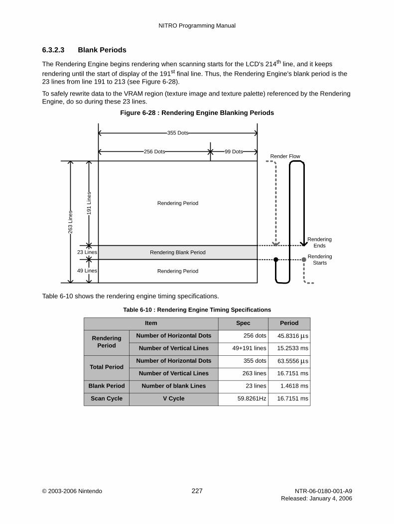
NITRO Programming Manual
6.3.2.3 Blank Periods
The Rendering Engine begins rendering when scanning starts for the LCD's 214th line, and it keeps rendering until the start of display of the 191st final line. Thus, the Rendering Engine's blank period is the 23 lines from line 191 to 213 (see Figure 6-28).
To safely rewrite data to the VRAM region (texture image and texture palette) referenced by the Rendering Engine, do so during these 23 lines.
Figure 6-28 : Rendering Engine Blanking Periods
Table 6-10 shows the rendering engine timing specifications.
Table 6-10 : Rendering Engine Timing Specifications
Item Spec Period
Rendering Period
Number of Horizontal Dots 256 dots 45.8316 μs
Number of Vertical Lines 49+191 lines 15.2533 ms
Total PeriodNumber of Horizontal Dots 355 dots 63.5556 μs
Number of Vertical Lines 263 lines 16.7151 ms
Blank Period Number of blank Lines 23 lines 1.4618 ms
Scan Cycle V Cycle 59.8261Hz 16.7151 ms
Rendering Period
256 Dots
355 Dots
191
Line
s
263
Line
s
99 Dots
Rendering Blank Period
Rendering Period
23 Lines
49 Lines
Rendering Starts
Rendering Ends
Render Flow
© 2003-2006 Nintendo 227 NTR-06-0180-001-A9Released: January 4, 2006
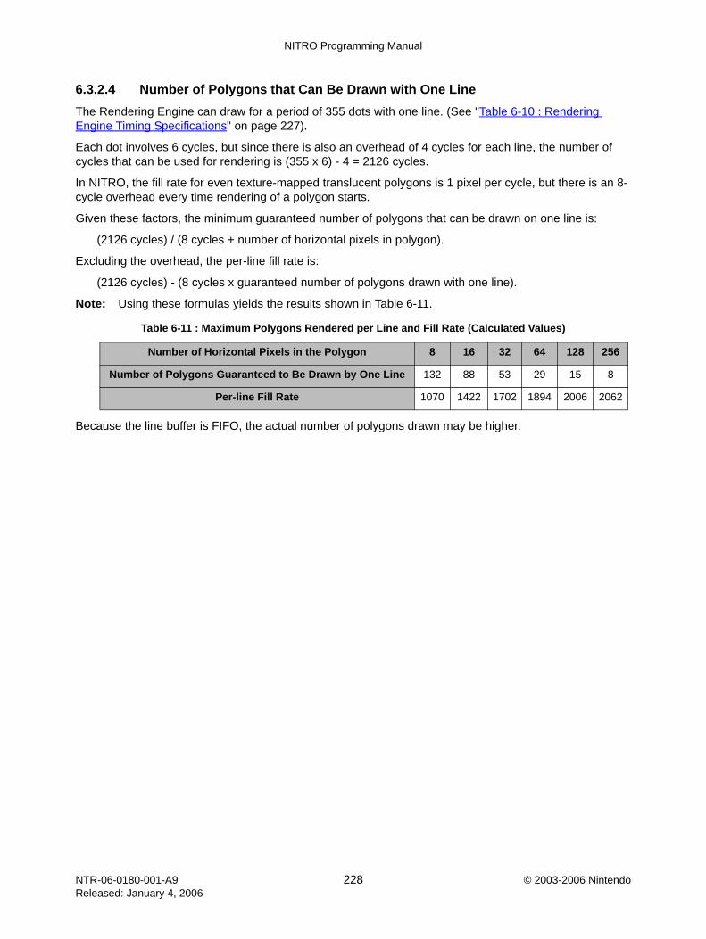
NITRO Programming Manual
6.3.2.4 Number of Polygons that Can Be Drawn with One LineThe Rendering Engine can draw for a period of 355 dots with one line. (See "Table 6-10 : Rendering Engine Timing Specifications" on page 227).
Each dot involves 6 cycles, but since there is also an overhead of 4 cycles for each line, the number of cycles that can be used for rendering is (355 x 6) - 4 = 2126 cycles.
In NITRO, the fill rate for even texture-mapped translucent polygons is 1 pixel per cycle, but there is an 8-cycle overhead every time rendering of a polygon starts.
Given these factors, the minimum guaranteed number of polygons that can be drawn on one line is:
(2126 cycles) / (8 cycles + number of horizontal pixels in polygon).
Excluding the overhead, the per-line fill rate is:
(2126 cycles) - (8 cycles x guaranteed number of polygons drawn with one line).
Note: Using these formulas yields the results shown in Table 6-11.
Table 6-11 : Maximum Polygons Rendered per Line and Fill Rate (Calculated Values)
Because the line buffer is FIFO, the actual number of polygons drawn may be higher.
Number of Horizontal Pixels in the Polygon 8 16 32 64 128 256
Number of Polygons Guaranteed to Be Drawn by One Line 132 88 53 29 15 8
Per-line Fill Rate 1070 1422 1702 1894 2006 2062
NTR-06-0180-001-A9 228 © 2003-2006 NintendoReleased: January 4, 2006

NITRO Programming Manual
6.3.3 Initializing the Rendering Buffers
6.3.3.1 Initializing with the Clear Registers
ClearColorAttr: Clear Color Attribute RegisterName: CLEAR_COLOR Address: 0x04000350 Attribute: W Initial value: 0x00000000
• Clear Polygon ID [d29–d24] : Polygon ID initial value
Sets the initial value of the opaque Polygon ID in the Attribute buffer. Whether edge marking is applied or not is determined by comparing the polygon ID and this Clear Polygon ID in the case of edges that can be clipped at the edge of the screen.
• α value[d20–d16] : Initial value of α
Sets the initial value of the α value in the Color buffer.
Normally set this to 0 when compositing with 2D.
• F[d15] : Fog enable flag
Sets the initial value of the fog enable flag in the Attribute buffer.
When compositing with the 2D screen, you can use this to control whether or not to apply fog to the rear plane.
This is effective when you want to clearly display a 2D background.
• Color[d14–d00] : Clear Color RGB values
Sets the Color buffer's initial RGB values.
The Color buffer in the Rendering Engine is (R:G:B = 6:6:6) bits, so the lower 1 bit is treated as 0 when the Clear Color value is 0, and as 1 when the value is nonzero.
ClearDepth: Clear Depth registerName: CLEAR_DEptH Address: 0x04000354 Attribute: W Initial value: 0x7FFF
• CLEARDEptH[d14–d00] : Clear Depth value
The Depth buffer in the Rendering Engine is 24 bits/pixel, so the Clear Depth value is used after shifting 9 bits to the left. The lower 9 bits are treated as 0 except when the Clear Depth value is 0x7FFF, in which case the lower 9 bits are treated as 1.
To read how this differs from the depth value in the different depth buffering methods, see "6.2.5 Depth Buffering" on page 163.
F BLUE GREEN RED
Clear Polygon ID value Fog Color
31 29 24 23 20 16 15 14 10 9 8 7 5 4 0
α
CLEARDEPTHClear Depth Value
15 14 8 7 0
© 2003-2006 Nintendo 229 NTR-06-0180-001-A9Released: January 4, 2006
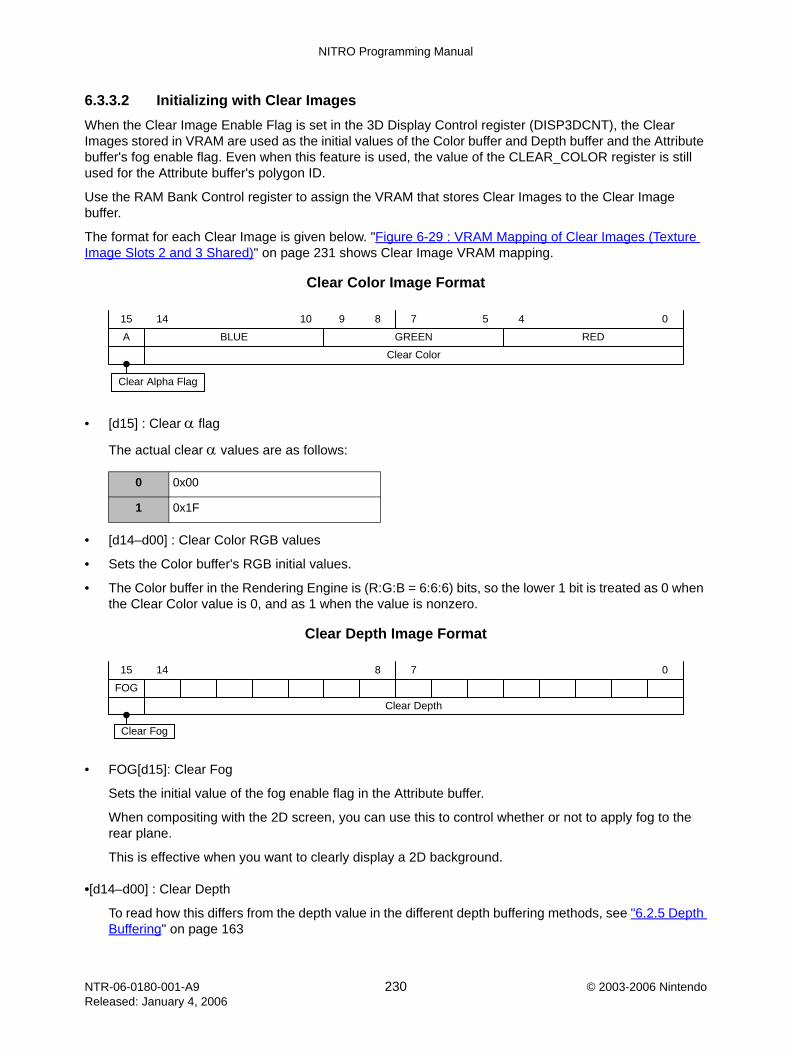
NITRO Programming Manual
6.3.3.2 Initializing with Clear ImagesWhen the Clear Image Enable Flag is set in the 3D Display Control register (DISP3DCNT), the Clear Images stored in VRAM are used as the initial values of the Color buffer and Depth buffer and the Attribute buffer's fog enable flag. Even when this feature is used, the value of the CLEAR_COLOR register is still used for the Attribute buffer's polygon ID.
Use the RAM Bank Control register to assign the VRAM that stores Clear Images to the Clear Image buffer.
The format for each Clear Image is given below. "Figure 6-29 : VRAM Mapping of Clear Images (Texture Image Slots 2 and 3 Shared)" on page 231 shows Clear Image VRAM mapping.
Clear Color Image Format
• [d15] : Clear α flag
The actual clear α values are as follows:
• [d14–d00] : Clear Color RGB values
• Sets the Color buffer's RGB initial values.
• The Color buffer in the Rendering Engine is (R:G:B = 6:6:6) bits, so the lower 1 bit is treated as 0 when the Clear Color value is 0, and as 1 when the value is nonzero.
Clear Depth Image Format
• FOG[d15]: Clear Fog
Sets the initial value of the fog enable flag in the Attribute buffer.
When compositing with the 2D screen, you can use this to control whether or not to apply fog to the rear plane.
This is effective when you want to clearly display a 2D background.
•[d14–d00] : Clear Depth
To read how this differs from the depth value in the different depth buffering methods, see "6.2.5 Depth Buffering" on page 163
0 0x00
1 0x1F
A BLUE GREEN RED
Clear Color
15 14 10 9 8 7 5 4 0
Clear Alpha Flag
FOG
Clear Depth
15 8 7 0
Clear Fog
14
NTR-06-0180-001-A9 230 © 2003-2006 NintendoReleased: January 4, 2006
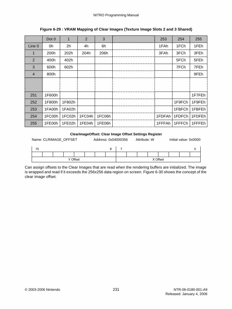
NITRO Programming Manual
Figure 6-29 : VRAM Mapping of Clear Images (Texture Image Slots 2 and 3 Shared)
ClearImageOffset: Clear Image Offset Settings RegisterName: CLRIMAGE_OFFSET Address: 0x04000356 Attribute: W Initial value: 0x0000
Can assign offsets to the Clear Images that are read when the rendering buffers are initialized. The image is wrapped and read if it exceeds the 256x256 data region on screen. Figure 6-30 shows the concept of the clear image offset.
Dot 0 1 2 3 253 254 255
Line 0 0h 2h 4h 6h 1FAh 1FCh 1FEh
1 200h 202h 204h 206h 3FAh 3FCh 3FEh
2 400h 402h 5FCh 5FEh
3 600h 602h 7FCh 7FEh
4 800h 9FEh
251 1F600h 1F7FEh
252 1F800h 1F802h 1F9FCh 1F9FEh
253 1FA00h 1FA02h 1FBFCh 1FBFEh
254 1FC00h 1FC02h 1FC04h 1FC06h 1FDFAh 1FDFCh 1FDFEh
255 1FE00h 1FE02h 1FE04h 1FE06h 1FFFAh 1FFFCh 1FFFEh
Y Offset X Offset
15 8 7 0
© 2003-2006 Nintendo 231 NTR-06-0180-001-A9Released: January 4, 2006
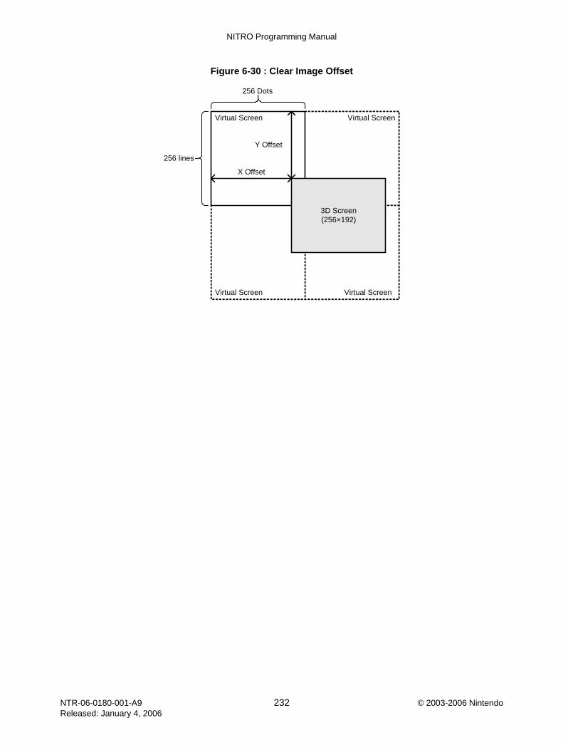
NITRO Programming Manual
Figure 6-30 : Clear Image Offset
256 Dots
256 lines
Y Offset
X Offset
3D Screen(256×192)
Virtual Screen
Virtual Screen Virtual Screen
Virtual Screen
NTR-06-0180-001-A9 232 © 2003-2006 NintendoReleased: January 4, 2006
NITRO Programming Manual
6.3.4 RasterizingRasterization is the process of dividing the polygon surface into pixels and writing them to a buffer. During rasterization, the Rendering Engine interpolates the pixel colors inside the polygon based on the vertex colors passed from the Geometry Engine.
The Rendering Engine stores the pixel colors in the Color buffer, and stores each pixel's polygon ID and fog enable flag in the Attribute buffer. The rendering engine first finishes rendering the opaque polygon that are in polygon list RAM, and then renders the translucent polygons.
6.3.4.1 Opaque Polygons
An opaque polygon is a polygon with an α value of 31 (α = 31).
• Polygon ID
This is stored in the region for opaque polygon IDs in the Attribute buffer when the polygon is rendered.
• Fog enable flag
When an opaque polygon is rendered, the fragment's fog enable flag overwrites the Attribute buffer's fog enable flag.
6.3.4.2 Translucent Polygons
A translucent polygon has either an α value between 1 and 30 (1 ≤ α ≤ 30) or a translucent texture applied.
Thus, this term also encompasses shadow polygons.
6.3.4.2.1 Polygons with 1 ≤ α ≤ 30
• Polygon ID
This is stored in the region for translucent polygon IDs in the Attribute buffer when the polygon is rendered.
When different translucent polygons overlap on the screen, a translucent polygon that uses the same polygon ID as another translucent polygon is not overwritten.
• Fog enable flag
When a translucent polygon is rendered, the fragment's fog enable flag and the Attribute buffer's fog enable flag are logically ANDed together and the result is written to the Attribute buffer.
This feature can be used to apply fog to everything except specific translucent polygons.
© 2003-2006 Nintendo 233 NTR-06-0180-001-A9Released: January 4, 2006

NITRO Programming Manual
6.3.4.2.2 Translucent texture mapped polygons
Translucent texture-mapped polygons (A3I5 and A5I3 textures) are stored in the translucent polygon region of the polygon list RAM, even if all of the texels are opaque. Therefore, they are rendered after opaque polygons. Notice that polygon ID and fog enable flag processing differs according to whether the pixel is opaque (α=31) or translucent (1 ≤ α ≤ 30), and therefore opaque pixels and translucent pixels may be mixed within a polygon.
• Polygon ID• Opaque pixels
When rendering polygons, these are stored in the attribute buffer’s opaque polygon ID area.
Therefore they are targeted for edge marking.• Translucent pixels
When rendering polygons, they are stored in the attribute buffer’s translucent polygon ID area.
If different translucent polygons overlap on the screen, translucent polygons that have the same polygon ID are not overwritten.
• Fog enable flag• Opaque pixels
Fragment fog enable flags are overwritten by the attribute buffer’s fog enable flags.• Translucent pixels
When a translucent polygon is drawn, the fragment's fog enable flag and the Attribute buffer's fog enable flag are ANDed together and the result is written to the Attribute buffer.
This feature can be used to apply fog to everything except specific translucent polygons.
6.3.4.3 Wireframes
A wireframe is a polygon with an α value of 0 (α = 0). In this case, α does not have its original meaning of opacity level. Instead, only the outline of the polygon (wireframe) is rendered. If it is clipped, the clipping boundary (a new side created due to clipping) is also rendered as a wireframe. To render a wireframe as translucent, map a translucent texture.
Note: The characteristics of the circuit do not permit a wireframe to be drawn semi-transparently.
About the Polygon IDWhen the wireframe is rendered, it is stored in the opaque polygon ID region of the attribute buffer. (Only the polygon ID of the wire is updated).
NTR-06-0180-001-A9 234 © 2003-2006 NintendoReleased: January 4, 2006
NITRO Programming Manual
6.3.4.4 Shadow PolygonsShadow volume is defined as the space that is not illuminated by light because the light has been obstructed by an object. A shadow, then, can be thought of as something that is generated in the region where the shadow volume intersects with another object. The polygon used to express a shadow volume is called a shadow polygon.
You create a shadow image that can be seen from the user’s perspective by creating only a mask image of the Stencil buffer when rendering the inner side of the shadow volume, and then excluding the mask region when drawing outside the shadow volume.
Shadow polygons used for masks and rendering can be differentiated by their polygon IDs.
Figure 6-31 shows the concept of shadow polygons. "Figure 6-32 : When Drawing the Shadow Polygon for the Mask" on page 237 describes rendering shadow polygons for masking. "Figure 6-32 : When Drawing the Shadow Polygon for the Mask" on page 237 describes rendering shadow polygons for drawing.
The procedure for attaching shadows using shadow polygons is as follows:
Polygon ID Classification
0 Shadow polygons for masks
1–63 Shadow polygons for drawing
1. Set rendering order
Because both mask- and draw-shadow polygons must be translucent and must exist in the drawing order (see the “Cautions” on page 238) set the translucent polygons to manual sort with SwapBuffers and set them to be rendered in the order they are transmitted to the Geometry Engine.
↓2. Draw the shadow polygon for the mask
Set the polygon attributes to [Draw only the back surface], [ID = 0], [α = 1 - 30] and [Shadow polygon] and draw the mask-shadow polygon. The rendering engine does not update the color buffer and creates only the mask images with 1 set in the stencil buffer.
↓3. Draw the shadow polygon for rendering
Next, set the polygon attributes to [Draw both surfaces], [ID = 1–63], [α = 1–30] and [Shadow polygon] and draw the shadow polygons for rendering. The rendering engine first reads the stencil buffer and, if the value is 1, resets it to 0; if the value is 0, the engine attempts to draw to the color buffer.
• Polygon ID
The draw-shadow polygon is drawn at this time only if its ID differs from both the ID of the opaque polygon and the ID of the translucent polygon in the Attribute buffer. This specification prevents an object from casting a shadow on itself by setting the same polygon ID for both the object and the draw-shadow polygon.
When multiple shadows overlap, you can control whether to overlay them or not by setting them to the same polygon ID.
• Fog Enable Flag
When a shadow polygon is rendered, the results of a logical AND applied to the fragment's fog enable flag and the Attribute buffer's fog enable flag are written to the Attribute buffer. With this feature, it is possible to excluded shaded areas from fog.
(Example: A spotlight can be expressed by excluding an area from black fog.)
© 2003-2006 Nintendo 235 NTR-06-0180-001-A9Released: January 4, 2006

NITRO Programming Manual
• Shadow Volume
Figure 6-31 : Shadow Volume
• Shadow volume shape
In principle, the shadow volume takes the shape of a closed 3D shape. Note the “Cautions” on page 238 if you plan to use an open 3D shape in order to reduce the number of polygons.
• Shadow volume direction
To create the shadow of a spherical object, a cylinder-shaped shadow volume is created on the straight line defined by the light source and the spherical object.
• Shadow volume position
The cylinder-shaped shadow volume is located where it cannot be seen from the light source (a place not illuminated by the light of the sphere).
• Shadow volume length
The shadow is drawn on the surface of the object that is located inside the shadow volume. Thus, the length of the shadow volume should be long enough to pass through the surface of the object on which you want shadow to be drawn.
Light Source
Shadow Volume
Object that Casts Shadow
Other Object (Normal Polygon)
Shadow
NTR-06-0180-001-A9 236 © 2003-2006 NintendoReleased: January 4, 2006
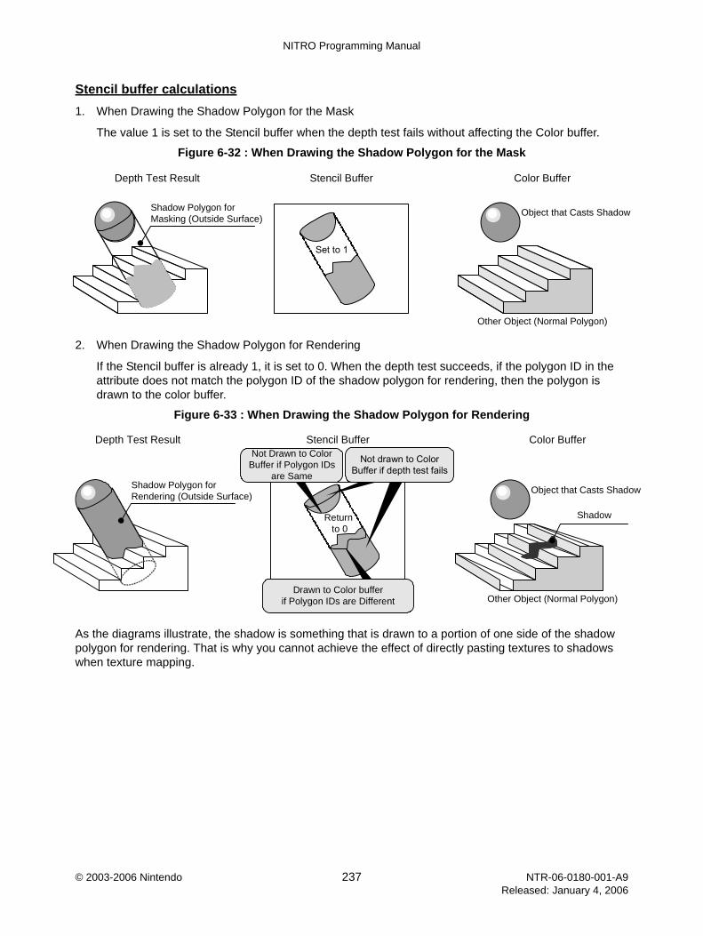
NITRO Programming Manual
Stencil buffer calculations1. When Drawing the Shadow Polygon for the Mask
The value 1 is set to the Stencil buffer when the depth test fails without affecting the Color buffer.
Figure 6-32 : When Drawing the Shadow Polygon for the Mask
2. When Drawing the Shadow Polygon for Rendering
If the Stencil buffer is already 1, it is set to 0. When the depth test succeeds, if the polygon ID in the attribute does not match the polygon ID of the shadow polygon for rendering, then the polygon is drawn to the color buffer.
Figure 6-33 : When Drawing the Shadow Polygon for Rendering
As the diagrams illustrate, the shadow is something that is drawn to a portion of one side of the shadow polygon for rendering. That is why you cannot achieve the effect of directly pasting textures to shadows when texture mapping.
Depth Test Result Stencil Buffer Color Buffer
Shadow Polygon for Masking (Outside Surface)
Object that Casts Shadow
Other Object (Normal Polygon)
Set to 1
Depth Test Result Stencil Buffer Color Buffer
Shadow Polygon forRendering (Outside Surface)
Object that Casts Shadow
Shadow
Other Object (Normal Polygon)
Not drawn to ColorBuffer if depth test fails
Not Drawn to ColorBuffer if Polygon IDs
are Same
Drawn to Color bufferif Polygon IDs are Different
Return to 0
© 2003-2006 Nintendo 237 NTR-06-0180-001-A9Released: January 4, 2006
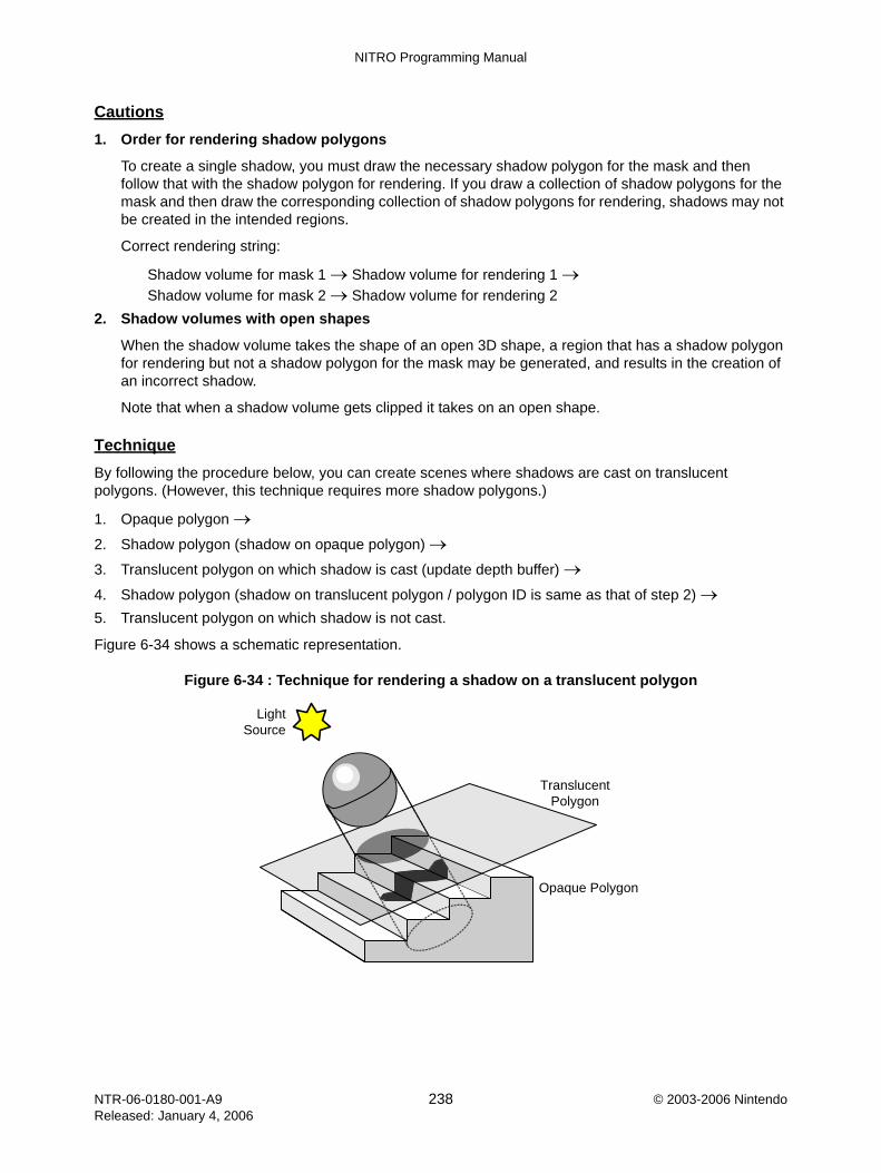
NITRO Programming Manual
Cautions1. Order for rendering shadow polygons
To create a single shadow, you must draw the necessary shadow polygon for the mask and then follow that with the shadow polygon for rendering. If you draw a collection of shadow polygons for the mask and then draw the corresponding collection of shadow polygons for rendering, shadows may not be created in the intended regions.
Correct rendering string:
Shadow volume for mask 1 → Shadow volume for rendering 1 → Shadow volume for mask 2 → Shadow volume for rendering 2
2. Shadow volumes with open shapes
When the shadow volume takes the shape of an open 3D shape, a region that has a shadow polygon for rendering but not a shadow polygon for the mask may be generated, and results in the creation of an incorrect shadow.
Note that when a shadow volume gets clipped it takes on an open shape.
TechniqueBy following the procedure below, you can create scenes where shadows are cast on translucent polygons. (However, this technique requires more shadow polygons.)
1. Opaque polygon →2. Shadow polygon (shadow on opaque polygon) →3. Translucent polygon on which shadow is cast (update depth buffer) →4. Shadow polygon (shadow on translucent polygon / polygon ID is same as that of step 2) →5. Translucent polygon on which shadow is not cast.
Figure 6-34 shows a schematic representation.
Figure 6-34 : Technique for rendering a shadow on a translucent polygon
Light Source
Opaque Polygon
Translucent Polygon
NTR-06-0180-001-A9 238 © 2003-2006 NintendoReleased: January 4, 2006
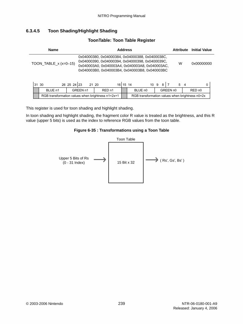
NITRO Programming Manual
6.3.4.5 Toon Shading/Highlight Shading
ToonTable: Toon Table Register
This register is used for toon shading and highlight shading.
In toon shading and highlight shading, the fragment color R value is treated as the brightness, and this R value (upper 5 bits) is used as the index to reference RGB values from the toon table.
Figure 6-35 : Transformations using a Toon Table
Name Address Attribute Initial Value
TOON_TABLE_x (x=0–15)
0x04000380, 0x04000384, 0x04000388, 0x0400038C, 0x04000390, 0x04000394, 0x04000398, 0x0400039C, 0x040003A0, 0x040003A4, 0x040003A8, 0x040003AC, 0x040003B0, 0x040003B4, 0x040003B8, 0x040003BC
W 0x00000000
BLUE n1 GREEN n1 RED n1 BLUE n0 GREEN n0 RED n0RGB transformation values when brightness n1=2x+1 RGB transformation values when brightness n0=2x
31 30 26 25 24 23 21 20 16 15 14 10 9 8 7 5 4 0
15 Bit x 32
Toon Table
Upper 5 Bits of Rs(0 - 31 Index) ( Rs', Gs', Bs' )
© 2003-2006 Nintendo 239 NTR-06-0180-001-A9Released: January 4, 2006

NITRO Programming Manual
6.3.4.5.1 Toon Shading
The fragment color R value is treated as the brightness, and this R value (the upper 5 bits) is used as the index to reference RGB values from the toon table to set the new fragment colors.
The texture color and the post-table-reference fragment color both have (R5:G5:B5 = 5:5:5) number of bits, so before the texture-blending computation is conducted, the following formulas are used to expand the number of bits to (R6:G6:B6 = 6:6:6).
Texture mapping involves the same equations used in Modulation mode, except that the toon table-transformed values are used for the fragment colors (see Table 6-12).
Table 6-12 : Texture Blending Equations (toon table)
(R, G, B, A) : Newly written fragment color (fractional parts resulting from calculations are truncated)
(Rt, Gt, Bt, At) : Texture color expanded to (R:G:B = 6:6:6) bits
(Rs, Gs, Bs, As) : Fragment color
(Rs’, Gs’, Bs’) : Fragment color expanded to (R:G:B = 6:6:6) bits after table conversion
Note: The toon table is referenced for fragment colors shared by all toon shading polygons. If you want every toon shading polygon to have different colors, then use textures to color even monochrome polygons.
Using ambient reflection color and emission color to raise the minimum value of the fragment color R value also narrows the effective range of R, and this coarsens the gradation of toon shading. Because material color looses its meaning when toon shading, we recommend that you use only diffusion reflection color so as to retain gradation.
R6 = R5 << 1 (When R5 is 0)
R6 = (R5 << 1) + 1 (When R5 is nonzero)
Type of Texture Translucent Texture Non-translucent Texture
TextureBlending Equations
R = { (Rt+1) x (Rs’+1) -1} / 64G = { (Gt+1) x (Gs’+1) -1} / 64B = { (Bt+1) x (Bs’+1) -1} / 64A = { (At+1) x (As+1) -1} / 64
R = { (Rt+1) x (Rs’+1) -1} / 64G = { (Gt+1) x (Gs’+1) -1} / 64B = { (Bt+1) x (Bs’+1) -1} / 64A = At x As
NTR-06-0180-001-A9 240 © 2003-2006 NintendoReleased: January 4, 2006
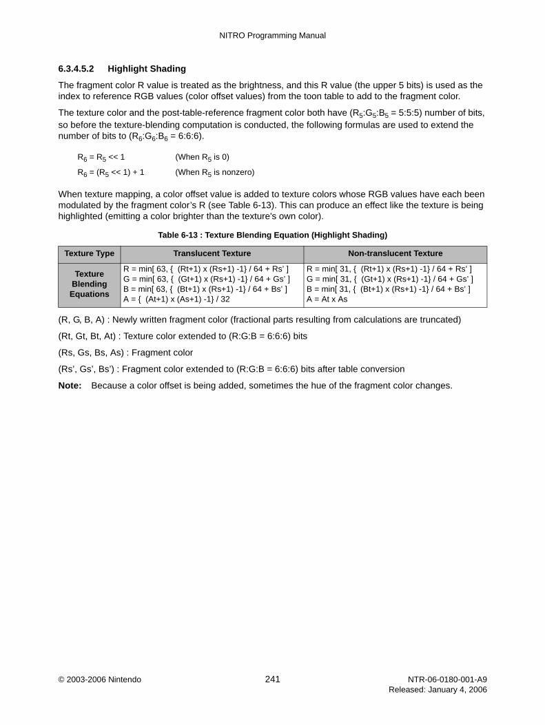
NITRO Programming Manual
6.3.4.5.2 Highlight Shading
The fragment color R value is treated as the brightness, and this R value (the upper 5 bits) is used as the index to reference RGB values (color offset values) from the toon table to add to the fragment color.
The texture color and the post-table-reference fragment color both have (R5:G5:B5 = 5:5:5) number of bits, so before the texture-blending computation is conducted, the following formulas are used to extend the number of bits to (R6:G6:B6 = 6:6:6).
When texture mapping, a color offset value is added to texture colors whose RGB values have each been modulated by the fragment color’s R (see Table 6-13). This can produce an effect like the texture is being highlighted (emitting a color brighter than the texture's own color).
Table 6-13 : Texture Blending Equation (Highlight Shading)
(R, G, B, A) : Newly written fragment color (fractional parts resulting from calculations are truncated)
(Rt, Gt, Bt, At) : Texture color extended to (R:G:B = 6:6:6) bits
(Rs, Gs, Bs, As) : Fragment color
(Rs’, Gs’, Bs’) : Fragment color extended to (R:G:B = 6:6:6) bits after table conversion
Note: Because a color offset is being added, sometimes the hue of the fragment color changes.
R6 = R5 << 1 (When R5 is 0)
R6 = (R5 << 1) + 1 (When R5 is nonzero)
Texture Type Translucent Texture Non-translucent Texture
Texture Blending Equations
R = min[ 63, { (Rt+1) x (Rs+1) -1} / 64 + Rs’ ]G = min[ 63, { (Gt+1) x (Rs+1) -1} / 64 + Gs’ ]B = min[ 63, { (Bt+1) x (Rs+1) -1} / 64 + Bs’ ]A = { (At+1) x (As+1) -1} / 32
R = min[ 31, { (Rt+1) x (Rs+1) -1} / 64 + Rs’ ]G = min[ 31, { (Gt+1) x (Rs+1) -1} / 64 + Gs’ ]B = min[ 31, { (Bt+1) x (Rs+1) -1} / 64 + Bs’ ]A = At x As
© 2003-2006 Nintendo 241 NTR-06-0180-001-A9Released: January 4, 2006
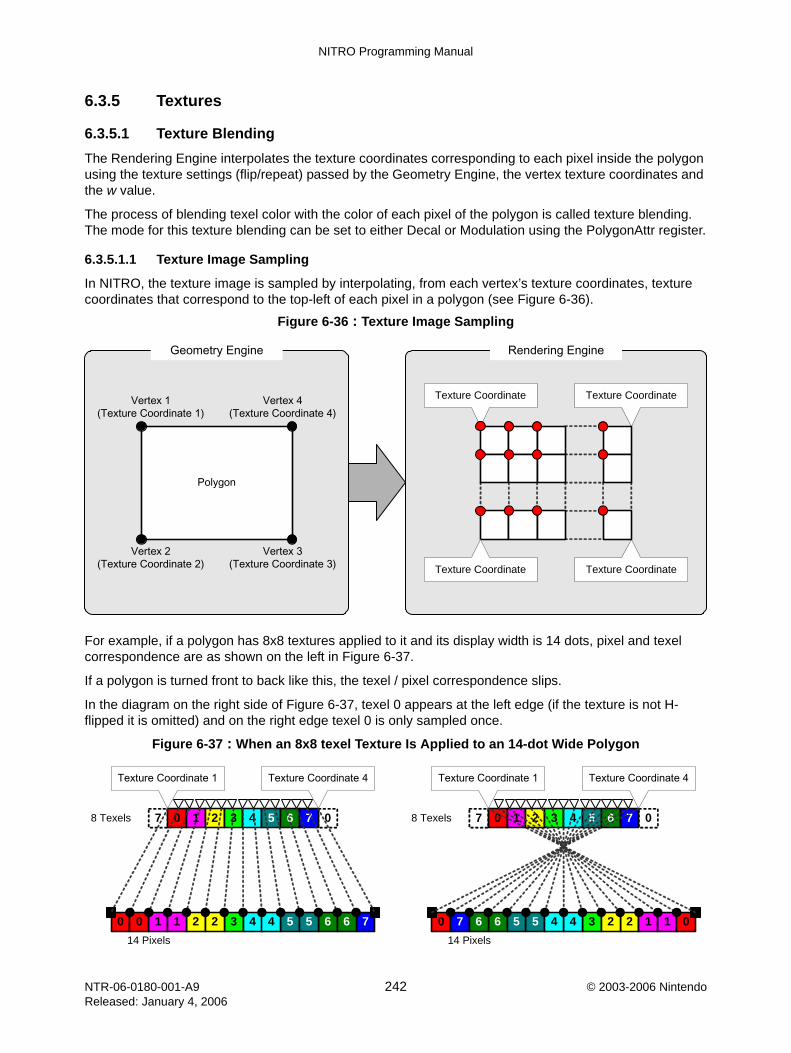
NITRO Programming Manual
6.3.5 Textures
6.3.5.1 Texture BlendingThe Rendering Engine interpolates the texture coordinates corresponding to each pixel inside the polygon using the texture settings (flip/repeat) passed by the Geometry Engine, the vertex texture coordinates and the w value.
The process of blending texel color with the color of each pixel of the polygon is called texture blending. The mode for this texture blending can be set to either Decal or Modulation using the PolygonAttr register.
6.3.5.1.1 Texture Image Sampling
In NITRO, the texture image is sampled by interpolating, from each vertex’s texture coordinates, texture coordinates that correspond to the top-left of each pixel in a polygon (see Figure 6-36).
Figure 6-36 : Texture Image Sampling
For example, if a polygon has 8x8 textures applied to it and its display width is 14 dots, pixel and texel correspondence are as shown on the left in Figure 6-37.
If a polygon is turned front to back like this, the texel / pixel correspondence slips.
In the diagram on the right side of Figure 6-37, texel 0 appears at the left edge (if the texture is not H-flipped it is omitted) and on the right edge texel 0 is only sampled once.
Figure 6-37 : When an 8x8 texel Texture Is Applied to an 14-dot Wide Polygon
Polygon
Vertex 1(Texture Coordinate 1)
Vertex 4(Texture Coordinate 4)
Vertex 2(Texture Coordinate 2)
Vertex 3(Texture Coordinate 3)
Texture Coordinate Texture Coordinate
Texture Coordinate
Geometry Engine Rendering Engine
Texture Coordinate
Texture Coordinate 1 Texture Coordinate 4
8 Texels
14 Pixels
7 00 1 2 3 4 5 6 7
0 1 2 3 4 5 6 70 1 2 4 5 6
Texture Coordinate 1 Texture Coordinate 4
8 Texels
14 Pixels
7 00 1 2 3 4 5 6 7
0 1234567 012456
NTR-06-0180-001-A9 242 © 2003-2006 NintendoReleased: January 4, 2006

NITRO Programming Manual
If a polygon has 8x8 textures applied to it and its display width is 8 dots, pixel and texel correspondence are as shown in Figure 6-38.
Figure 6-38 : When an 8x8 texel Texture Is Applied to an 8-dot Wide Polygon
When using polygons for 2D displays such as OBJ or BG, texels and pixels have a one to one correspondence. However, in a case such as this, when rendering a polygon that is mapped with an 8x8 texel texture on 8x8 pixels of an LCD, the front and back surfaces are displayed as shown in Figure 6-39.
Figure 6-39 : Displaying Front and Back Surfaces of an LCD
Texture Coordinate 1 Texture Coordinate 4
8 Texels
8 Texels
7 00 1 2 3 4 5 6 7
0 1 2 3 4 5 6 7
Texture Coordinate 1 Texture Coordinate 4
8 Texels
8 Texels
7 00 1 2 3 4 5 6 7
0 1234567
Front Surface
00 01 02 03 04 05 06 07
10 11 12 13 14 15 16 17
20 21 22 23 24 25 26 27
30 31 32 33 34 35 36 37
40 41 42 43 44 45 46 47
50 51 52 53 54 55 56 57
60 61 62 63 64 65 66 67
70 71 72 73 74 75 76 77
00 01020304050607
10 11121314151617
20 21222324252627
30 31323334353637
40 41424344454647
50 51525354555657
60 61626364656667
70 71727374757677
00 01020304050607
10 11121314151617
20 21222324252627
30 31323334353637
40 41424344454647
50 51525354555657
60 61626364656667
70 71727374757677
Horizontal Reflection of Polygons
180 Degree Rotation90 Degree Clockwise Rotation
(270 Degrees Counterclockwise)270 Degree Clockwise Rotation(90 Degrees Counterclockwise)
00
01
02
03
04
05
06
07
10
11
12
13
14
15
16
17
20
21
22
23
24
25
26
27
30
31
32
33
34
35
36
37
40
41
42
43
44
45
46
47
50
51
52
53
54
55
56
57
60
61
62
63
64
65
66
67
70
71
72
73
74
75
76
77
00
01
02
03
04
05
06
07
10
11
12
13
14
15
16
17
20
21
22
23
24
25
26
27
30
31
32
33
34
35
36
37
40
41
42
43
44
45
46
47
50
51
52
53
54
55
56
57
60
61
62
63
64
65
66
67
70
71
72
73
74
75
76
77
00 01 02 03 04 05 06 07
10 11 12 13 14 15 16 17
20 21 22 23 24 25 26 27
30 31 32 33 34 35 36 37
40 41 42 43 44 45 46 47
50 51 52 53 54 55 56 57
60 61 62 63 64 65 66 67
70 71 72 73 74 75 76 77
Vertical Reflection of Polygons
© 2003-2006 Nintendo 243 NTR-06-0180-001-A9Released: January 4, 2006

NITRO Programming Manual
6.3.5.1.2 Decal Mode
Depending on the texture's α value, either the result of Gouraud shading of the vertex color created by the lighting process (fragment color), or the texture's color value is displayed.
For translucent textures, blending is done with the texture's α value.
Table 6-14 shows the texture blending expression used in decal mode.
The texture color has (R5:G5:B5 = 5:5:5) number of bits, so before the texture-blending computation is conducted, the following formulas are used to expand the number of bits to (R6:G6:B6 = 6:6:6).
Table 6-14 : Texture Blending Equations (decal mode)
(R, G, B, A) : Newly written fragment color (fractional parts resulting from calculations are truncated)
(Rt, Gt, Bt, At) : Texture color expanded to (R:G:B = 6:6:6) bits
(Rs, Gs, Bs, As) : Fragment color
R6 = R5 << 1 (When R5 is 0)
R6 = (R5 << 1) + 1 (When R5 is nonzero)
Texture Type Translucent Texture Non-translucent Texture
TextureBlending Equations
R = {At x Rt + (31 - At) Rs} / 32G = {At x Gt + (31 - At) Gs} / 32B = {At x Bt + (31 - At) Bs} / 32A = As
Handling exceptions:When At = 0, (R, G, B, A) = (Rs, Gs, Bs, As) is used.When At =31, (R, G, B, A) = (Rt, Gt, Bt, As) is used.
R = At x Rt + (1 - At) RsG = At x Gt + (1 - At) GsB = At x Bt + (1 - At) BsA = As
NTR-06-0180-001-A9 244 © 2003-2006 NintendoReleased: January 4, 2006

NITRO Programming Manual
6.3.5.1.3 Modulation Mode
The result of the Gouraud shading of the vertex color (fragment color) created by the lighting process is modulated by the texture's color value and displayed.
Table 6-15 shows the texture blending expressions used in modulation mode.
The texture color's fragment color has (R5:G5:B5 = 5:5:5) number of bits, so before the texture-blending computation is conducted, the following formulas are used to expand the number of bits to (R6:G6:B6 = 6:6:6).
Table 6-15 : Texture Blending expressions (modulation mode)
(R, G, B, A) : Newly written fragment color (fractional parts resulting from calculations are truncated)
(Rt, Gt, Bt, At) : Texture color expanded to (R:G:B = 6:6:6) bits
(Rs, Gs, Bs, As) : Fragment color
R6 = R5 << 1 (When R5 is 0)
R6 = (R5 << 1) + 1 (When R5 is nonzero)
Type of Texture Translucent Texture Non-translucent Texture
TextureBlending Equations
R = { (Rt+1) x (Rs+1) -1} / 32G = { (Gt+1) x (Gs+1) -1} / 32B = { (Bt+1) x (Bs+1) -1} / 32A = { (At+1) x (As+1) -1} / 32
R = { (Rt+1) x (Rs+1) -1} / 32G = { (Gt+1) x (Gs+1) -1} / 32B = { (Bt+1) x (Bs+1) -1} / 32A = At x As
© 2003-2006 Nintendo 245 NTR-06-0180-001-A9Released: January 4, 2006

NITRO Programming Manual
6.3.5.2 Texture FormatsNITRO can handle seven different texture formats. Table 6-16 lists the texture formats.
Table 6-16 : List of Texture Formats
Note: Palette Base Boundary is the amount by which the address is increased when the palette base is increased by 1 by the TexPlttBase command
6.3.5.2.1 Texture Images
The Rendering Engine references the texture image slot's texture image in the format specified by the TexImageParam command. The texture image is composed of texel data.
6.3.5.2.1.1 4-Color Palette Textures
Texel Data Format
• T7–T0 : Texel Data
Specifies the texture color palette color number (0–3)
Display Texture
Format Number of Selectable Colors for 1 Texel
PaletteBase
Boundary (see note)
α ValueBits
Number of Bits per Texel
4-Color Palette Texture 4 0x08 0 2
16-Color Palette Texture 16 0x10 0 4
256-Color Palette Texture 256 0x10 0 8
4x4 TexelCompressed Texture
4(every 4x4 texels) 0x10 0
3 (Includes palette index
data)
A3I5 Translucent Texture 32 0x10 3 8
A5I3 Translucent Texture 8 0x10 5 8
Direct Color Texture 32,768 Palette not used 1 16
T0 T1 T2 T3 T4 T5 T6 T7
T7 T6 T5 T4 T3 T2 T1 T08 Texels of Data (2 bits / texel)
15 14 13 12 11 10 9 8 7 6 5 4 3 2 1 0
NTR-06-0180-001-A9 246 © 2003-2006 NintendoReleased: January 4, 2006
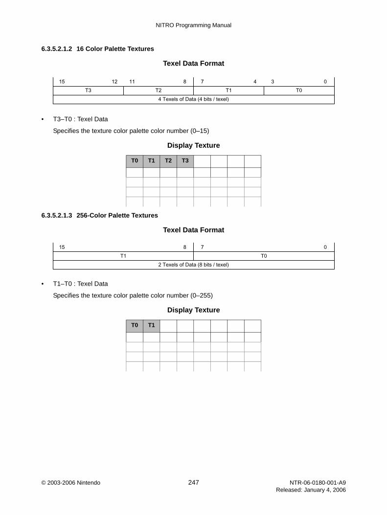
NITRO Programming Manual
6.3.5.2.1.2 16 Color Palette Textures
Texel Data Format
• T3–T0 : Texel Data
Specifies the texture color palette color number (0–15)
Display Texture
6.3.5.2.1.3 256-Color Palette Textures
Texel Data Format
• T1–T0 : Texel Data
Specifies the texture color palette color number (0–255)
Display Texture
T0 T1 T2 T3
T0 T1
T3 T2 T1 T04 Texels of Data (4 bits / texel)
15 12 11 8 7 4 3 0
T1 T02 Texels of Data (8 bits / texel)
15 8 7 0
© 2003-2006 Nintendo 247 NTR-06-0180-001-A9Released: January 4, 2006

NITRO Programming Manual
6.3.5.2.1.4 4x4 Texel Compression Textures
This format can obtain the compression effect by dividing the image into 4x4 pixel blocks, and then converting them to images with palettes with 2-bit indexes.
Texel Data Format
• T33–T00 : Texel Data
Specifies the color number (0–3)
Display Texture
T00 T01 T02 T03
T10 T11 T12 T13
T20 T21 T22 T23
T30 T31 T32 T33
T33 T32 T31 T30 T23 T22 T21 T20 T13 T12 T11 T10 T03 T02 T01 T004 x 4 Texels of Data (2 bits / texel)
31 24 23 16 15 8 7 0
NTR-06-0180-001-A9 248 © 2003-2006 NintendoReleased: January 4, 2006
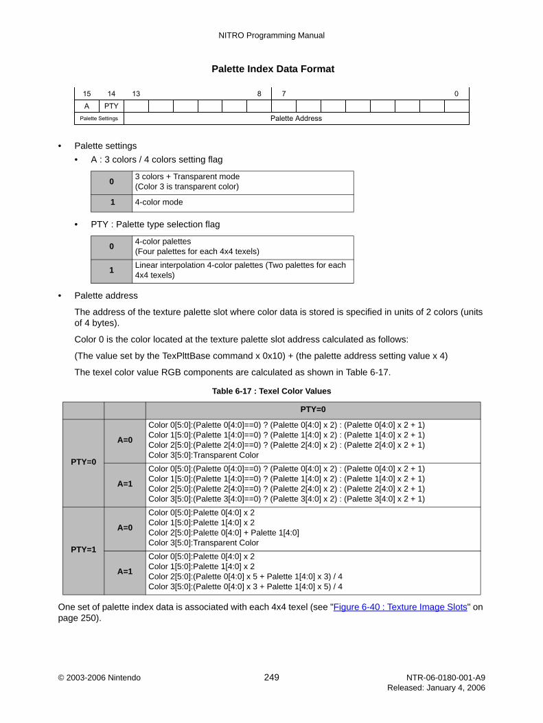
NITRO Programming Manual
Palette Index Data Format
• Palette settings• A : 3 colors / 4 colors setting flag
• PTY : Palette type selection flag
• Palette address
The address of the texture palette slot where color data is stored is specified in units of 2 colors (units of 4 bytes).
Color 0 is the color located at the texture palette slot address calculated as follows:
(The value set by the TexPlttBase command x 0x10) + (the palette address setting value x 4)
The texel color value RGB components are calculated as shown in Table 6-17.
Table 6-17 : Texel Color Values
One set of palette index data is associated with each 4x4 texel (see "Figure 6-40 : Texture Image Slots" on page 250).
0 3 colors + Transparent mode(Color 3 is transparent color)
1 4-color mode
0 4-color palettes(Four palettes for each 4x4 texels)
1 Linear interpolation 4-color palettes (Two palettes for each 4x4 texels)
PTY=0
PTY=0
A=0
Color 0[5:0]:(Palette 0[4:0]==0) ? (Palette 0[4:0] x 2) : (Palette 0[4:0] x 2 + 1)Color 1[5:0]:(Palette 1[4:0]==0) ? (Palette 1[4:0] x 2) : (Palette 1[4:0] x 2 + 1)Color 2[5:0]:(Palette 2[4:0]==0) ? (Palette 2[4:0] x 2) : (Palette 2[4:0] x 2 + 1)Color 3[5:0]:Transparent Color
A=1
Color 0[5:0]:(Palette 0[4:0]==0) ? (Palette 0[4:0] x 2) : (Palette 0[4:0] x 2 + 1)Color 1[5:0]:(Palette 1[4:0]==0) ? (Palette 1[4:0] x 2) : (Palette 1[4:0] x 2 + 1)Color 2[5:0]:(Palette 2[4:0]==0) ? (Palette 2[4:0] x 2) : (Palette 2[4:0] x 2 + 1)Color 3[5:0]:(Palette 3[4:0]==0) ? (Palette 3[4:0] x 2) : (Palette 3[4:0] x 2 + 1)
PTY=1
A=0
Color 0[5:0]:Palette 0[4:0] x 2Color 1[5:0]:Palette 1[4:0] x 2Color 2[5:0]:Palette 0[4:0] + Palette 1[4:0]Color 3[5:0]:Transparent Color
A=1
Color 0[5:0]:Palette 0[4:0] x 2Color 1[5:0]:Palette 1[4:0] x 2Color 2[5:0]:(Palette 0[4:0] x 5 + Palette 1[4:0] x 3) / 4Color 3[5:0]:(Palette 0[4:0] x 3 + Palette 1[4:0] x 5) / 4
A PTYPalette Settings Palette Address
15 14 13 8 7 0
© 2003-2006 Nintendo 249 NTR-06-0180-001-A9Released: January 4, 2006

NITRO Programming Manual
Texture image slotsIn 4x4 texel compression mode, the texture image data and the texture palette index data should be mapped as follows:
• Texel data
Map to texture image slots 0 and 2.
• Texture palette index data
Map to texture image slot 1.
• Correspondence between texel data and texture palette index data
The texture palette index data which corresponds to the 4x4 texel data in the TIDAa address of texture image slot 0 should be placed in the (TIDAa/2) address of texture image slot 1.
The texture palette index data which corresponds to the 4x4 texel data in the TIDAb address of texture image slot 2 should be placed in the (0x10000 + (TIDAb/2)) address of texture image slot 1. (See Figure 6-40.)
Each 4x4 texel is associated with one set of texture palette index data. Individual texel colors take the color of the address (the texture color palette slot) specified by the texture palette index data as 0, and use the color number’s color designated by the texel data.
Figure 6-40 : Texture Image Slots
Note: Texture data is placed in slot 0 and slot 2. Because the address jumps, it is not possible to reference 1024x1024. In 4x4 texel compressed texture mode, use a texture size that is no larger than 1024x512.
TextureImage Data
0x10000+(TIAb /2)
Texture Image Slot 0
The Texture PaletteIndex Data of Slot 0
The texture PaletteIndex Data of Slot 2
Texture Image Slot 1 Texture Image Slot 2
0x00000
0x20000
0x00000
0x20000
0x00000
0x20000
TextureImage Data
TIAb
TIAa/2
0x10000
TIAa
NTR-06-0180-001-A9 250 © 2003-2006 NintendoReleased: January 4, 2006
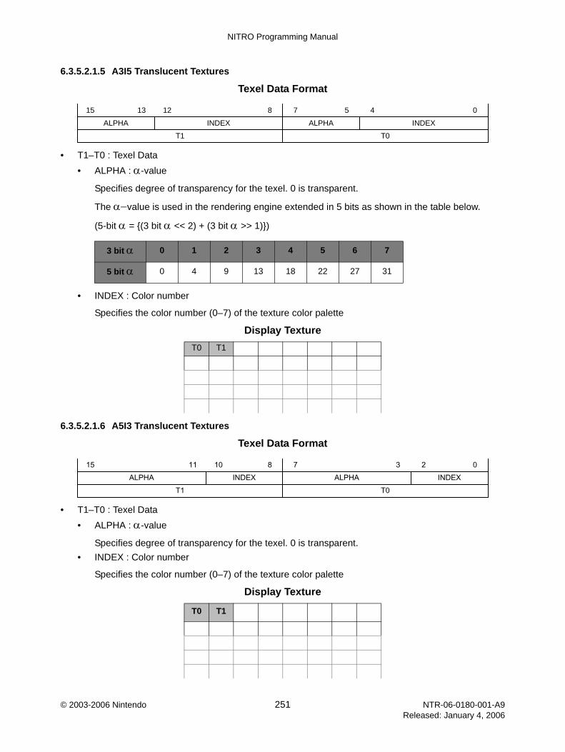
NITRO Programming Manual
6.3.5.2.1.5 A3I5 Translucent Textures
Texel Data Format
• T1–T0 : Texel Data• ALPHA : α-value
Specifies degree of transparency for the texel. 0 is transparent.
The α−value is used in the rendering engine extended in 5 bits as shown in the table below.
(5-bit α = {(3 bit α << 2) + (3 bit α >> 1)})
• INDEX : Color number
Specifies the color number (0–7) of the texture color palette
Display Texture
6.3.5.2.1.6 A5I3 Translucent Textures
Texel Data Format
• T1–T0 : Texel Data• ALPHA : α-value
Specifies degree of transparency for the texel. 0 is transparent.• INDEX : Color number
Specifies the color number (0–7) of the texture color palette
Display Texture
3 bit α 0 1 2 3 4 5 6 7
5 bit α 0 4 9 13 18 22 27 31
T0 T1
T0 T1
ALPHA INDEX ALPHA INDEX
T1 T0
15 8 7 01213 5 4
ALPHA INDEX ALPHA INDEXT1 T0
15 11 10 8 7 3 2 0
© 2003-2006 Nintendo 251 NTR-06-0180-001-A9Released: January 4, 2006
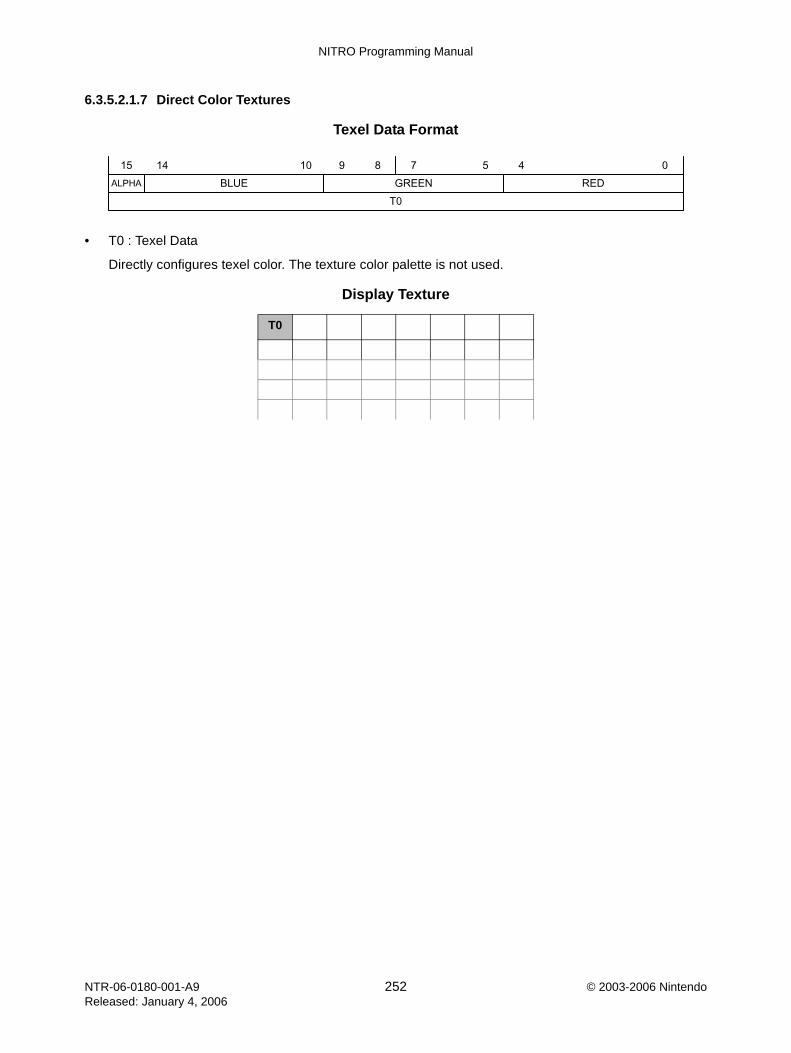
NITRO Programming Manual
6.3.5.2.1.7 Direct Color Textures
Texel Data Format
• T0 : Texel Data
Directly configures texel color. The texture color palette is not used.
Display Texture
T0
ALPHA BLUE GREEN REDT0
15 14 10 9 8 7 5 4 0
NTR-06-0180-001-A9 252 © 2003-2006 NintendoReleased: January 4, 2006
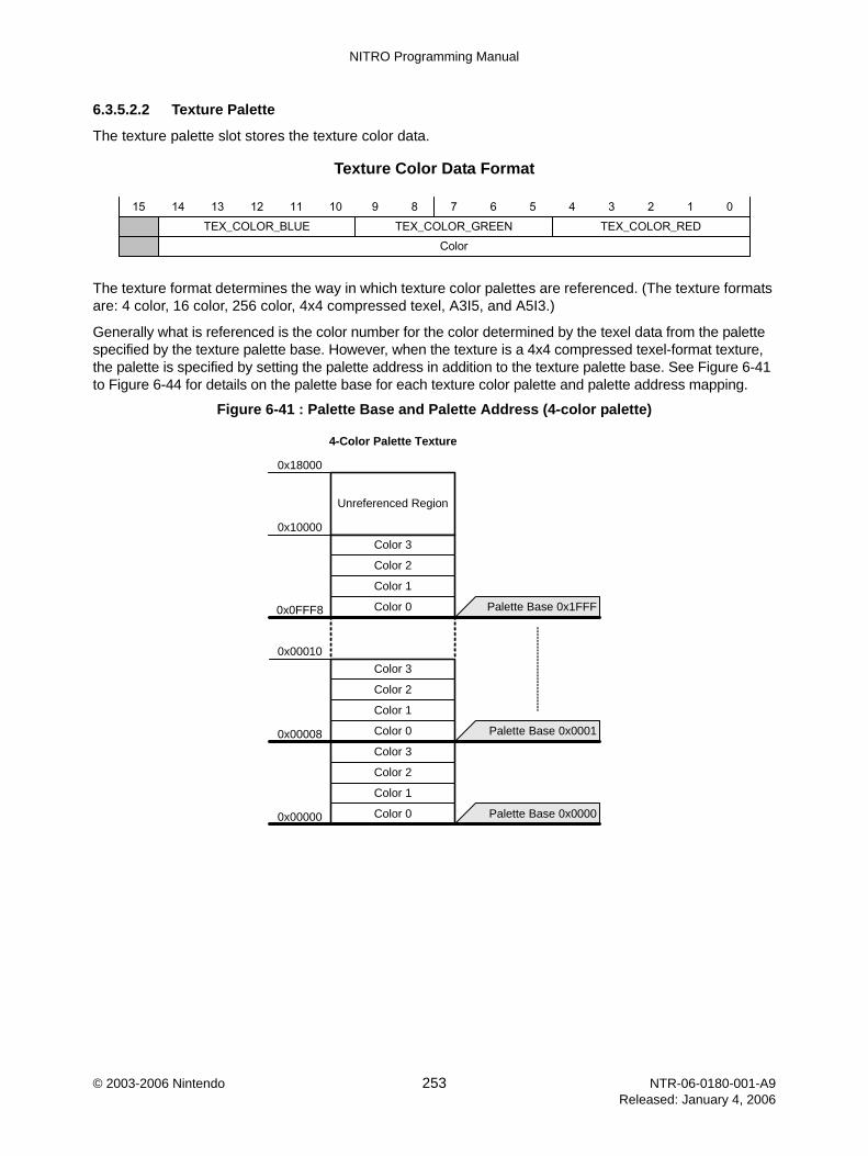
NITRO Programming Manual
6.3.5.2.2 Texture Palette
The texture palette slot stores the texture color data.
Texture Color Data Format
The texture format determines the way in which texture color palettes are referenced. (The texture formats are: 4 color, 16 color, 256 color, 4x4 compressed texel, A3I5, and A5I3.)
Generally what is referenced is the color number for the color determined by the texel data from the palette specified by the texture palette base. However, when the texture is a 4x4 compressed texel-format texture, the palette is specified by setting the palette address in addition to the texture palette base. See Figure 6-41 to Figure 6-44 for details on the palette base for each texture color palette and palette address mapping.
Figure 6-41 : Palette Base and Palette Address (4-color palette)
TEX_COLOR_BLUE TEX_COLOR_GREEN TEX_COLOR_REDColor
15 14 13 12 11 10 9 8 7 6 5 4 3 2 1 0
Color 0
Color 1
Color 2
Color 3
Color 0
Color 1
Unreferenced Region
0x00000
0x00008
0x0FFF8
0x10000
0x18000
Palette Base 0x0000
Palette Base 0x1FFF
Color 2
Color 3
4-Color Palette Texture
Color 0
Color 1
Color 2
Color 30x00010
Palette Base 0x0001
© 2003-2006 Nintendo 253 NTR-06-0180-001-A9Released: January 4, 2006
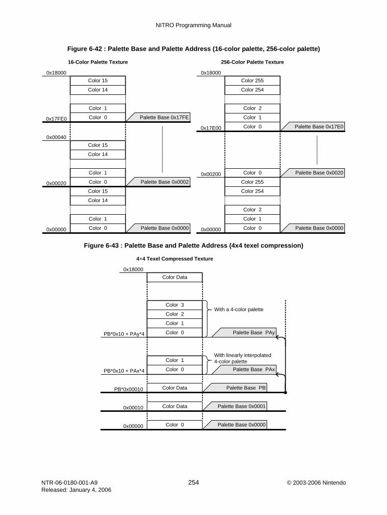
NITRO Programming Manual
Figure 6-42 : Palette Base and Palette Address (16-color palette, 256-color palette)
Figure 6-43 : Palette Base and Palette Address (4x4 texel compression)
Color 0
Color 0
Color 1
Color 14
Color 15
0x00000
0x00020
0x17FE0
0x18000
Palette Base 0x0000
Palette Base 0x17FEColor 0
Color 1
Color 14
Color 15
Color 0
Color 1
Color 254
Color 255
0x00000
0x00200
0x17E00
0x18000
Palette Base 0x0000
Palette Base 0x17E0Color 0
Color 1
Color 254
Color 255
16-Color Palette Texture 256-Color Palette Texture
Color 0
Color 1
Color 14
Color 150x00040
Palette Base 0x0002
Color 2
Color 2
Palette Base 0x0020
4×4 Texel Compressed Texture
0x00000 Palette Base 0x0000Color 0
Color Data
Color 0
Color 1
Color 0
Color 1
Color 2
Color 3
0x00010 Color Data Palette Base 0x0001
PB*0x10 + PAx*4 Palette Base PAx
PB*0x00010 Color Data Palette Base PB
Palette Base PAyPB*0x10 + PAy*4
0x18000
With a 4-color palette
With linearly interpolated 4-color palette
NTR-06-0180-001-A9 254 © 2003-2006 NintendoReleased: January 4, 2006

NITRO Programming Manual
For a 4x4 compressed texel-format texture, the palette address is set by the palette base and the palette address. Color numbers 0 to 3 are referenced for a four-color palette, but only color numbers 0 and 1 are referenced for a linear interpolated four-color palette. The remaining two colors applied to the texels are calculated from Color 0 and Color 1.
Even for a four-color palette, transparent is used without referencing Color 3 when the mode is set to Three Colors + Transparent.
Figure 6-44 : Palette Base and Palette Address (A3I5, A5I3)
Color 0
Color 1
Color 30
0x00000
0x00040
0x18000
Palette Base 0x0000
Color 1
Color 30
Color 31
Color 0
0x00080
Palette Base 0x0004
Color 1
Color 30
Color 31
Color 31
Color 0
A3I5 Texture
Color 0
Color 1
Color 7
0x00000
0x00010
0x17FF0
0x18000
Palette Base 0x0000
Palette Base 0x17FFColor 0
Color 1
Color 0
Color 1
0x00020
Palette Base 0x0001
Color 7
Palette Base 0x0001Color 0
Color 7
Color 1
Color 7
A5I3 Texture
0x17FC0 Palette Base 0x17FC
© 2003-2006 Nintendo 255 NTR-06-0180-001-A9Released: January 4, 2006
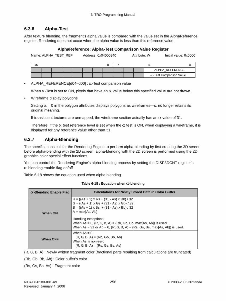
NITRO Programming Manual
6.3.6 Alpha-TestAfter texture blending, the fragment's alpha value is compared with the value set in the AlphaReference register. Rendering does not occur when the alpha value is less than this reference value.
AlphaReference: Alpha-Test Comparison Value RegisterName: ALPHA_TEST_REF Address: 0x04000340 Attribute: W Initial value: 0x0000
• ALPHA_REFERENCE[d04–d00] : α-Test comparison value
When α-Test is set to ON, pixels that have an α value below this specified value are not drawn.
• Wireframe display polygons
Setting α = 0 in the polygon attributes displays polygons as wireframes—α no longer retains its original meaning.
If translucent textures are unmapped, the wireframe section actually has an α value of 31.
Therefore, if the α test reference level is set when the α test is ON, when displaying a wireframe, it is displayed for any reference value other than 31.
6.3.7 Alpha-BlendingThe specifications call for the Rendering Engine to perform alpha-blending by first creating the 3D screen before alpha-blending with the 2D screen. alpha-blending with the 2D screen is performed using the 2D graphics color special effect functions.
You can control the Rendering Engine's alpha-blending process by setting the DISP3DCNT register's α-blending enable flag on/off.
Table 6-18 shows the equation used when alpha blending.
Table 6-18 : Equation when α-blending
(R, G, B, A) : Newly written fragment color (fractional parts resulting from calculations are truncated)
(Rb, Gb, Bb, Ab) : Color buffer's color
(Rs, Gs, Bs, As) : Fragment color
α-Blending Enable Flag Calculations for Newly Stored Data in Color Buffer
When ON
R = {(As + 1) x Rs + (31 - As) x Rb} / 32G = {(As + 1) x Gs + (31 - As) x Gb} / 32B = {(As + 1) x Bs + (31 - As) x Bb} / 32A = max[As, Ab]
Handling exceptions:When As = 0, (R, G, B, A) = (Rb, Gb, Bb, max[As, Ab]) is used.When As = 31 or Ab = 0, (R, G, B, A) = (Rs, Gs, Bs, max[As, Ab]) is used.
When OFF
When As = 0 (R, G, B, A) = (Rb, Gb, Bb, Ab)When As is non-zero (R, G, B, A) = (Rs, Gs, Bs, As)
ALPHA_REFERENCE
-Test Comparison Value
15 8 7 4 0
α
NTR-06-0180-001-A9 256 © 2003-2006 NintendoReleased: January 4, 2006
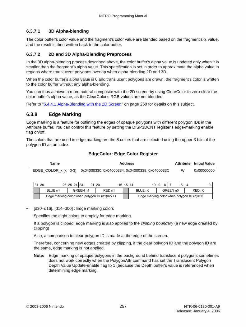
NITRO Programming Manual
6.3.7.1 3D Alpha-blending
The color buffer's color value and the fragment's color value are blended based on the fragment's α value, and the result is then written back to the color buffer.
6.3.7.2 2D and 3D Alpha-Blending PreprocessIn the 3D alpha-blending process described above, the color buffer's alpha value is updated only when it is smaller than the fragment's alpha value. This specification is set in order to approximate the alpha value in regions where translucent polygons overlap when alpha-blending 2D and 3D.
When the color buffer's alpha value is 0 and translucent polygons are drawn, the fragment's color is written to the color buffer without any alpha-blending.
You can thus achieve a more natural composite with the 2D screen by using ClearColor to zero-clear the color buffer's alpha value, as the ClearColor's RGB values are not blended.
Refer to "6.4.4.1 Alpha-Blending with the 2D Screen" on page 268 for details on this subject.
6.3.8 Edge MarkingEdge marking is a feature for outlining the edges of opaque polygons with different polygon IDs in the Attribute buffer. You can control this feature by setting the DISP3DCNT register's edge-marking enable flag on/off.
The colors that are used in edge marking are the 8 colors that are selected using the upper 3 bits of the polygon ID as an index.
EdgeColor: Edge Color Register
• [d30–d16], [d14–d00] : Edge marking colors
Specifies the eight colors to employ for edge marking.
If a polygon is clipped, edge marking is also applied to the clipping boundary (a new edge created by clipping)
Also, a comparison to clear polygon ID is made at the edge of the screen.
Therefore, concerning new edges created by clipping, if the clear polygon ID and the polygon ID are the same, edge marking is not applied.
Note: Edge marking of opaque polygons in the background behind translucent polygons sometimes does not work correctly when the PolygonAttr command has set the Translucent Polygon Depth Value Update-enable flag to 1 (because the Depth buffer's value is referenced when determining edge marking.
Name Address Attribute Initial Value
EDGE_COLOR_x (x =0-3) 0x04000330, 0x04000334, 0x04000338, 0x0400033C W 0x00000000
BLUE n1 GREEN n1 RED n1 BLUE n0 GREEN n0 RED n0Edge marking color when polygon ID (n1)=2x+1 Edge marking color when polygon ID (n)=2x
31 30 26 25 24 23 21 20 16 15 14 10 9 8 7 5 4 0
© 2003-2006 Nintendo 257 NTR-06-0180-001-A9Released: January 4, 2006

NITRO Programming Manual
6.3.9 Fog BlendingFog blending is the process of blending each pixel color with fog color in proportion to the depth value. The fog-blending process can create a fog effect on the screen, hiding from the player the far-plane clipping and rejection processes that do not arise in the natural world. You can control this feature by setting the DISP3DCNT register's fog enable flag on/off.
6.3.9.1 3D FogIn OpenGL, the fog process is done on each polygon when it is drawn. But with NITRO, the fog process is performed on the color buffer where all polygons have been drawn, after the edge marking process.
Because of this specification, you can produce effects where fog is applied to everywhere except a specified region. However, applying fog to regions where translucent polygons are rendered can produce unnatural effects. If this happens, use the PolygonAttr command to set the Translucent Polygon Depth Value Update-enable Flag for visual approximation.
Note: If you update the depth value you must also conduct a Z sort or else some parts inside regions where translucent polygons overlap may not get rendered.
FogColor: Fog Color RegisterName: FOG_COLOR Address: 0x04000358 Attribute: W Initial value: 0x00000000
This specifies the fog color.
When compositing with the 2D screen's background, you can achieve the effect of the object dissolving into the 2D screen if you set the fog α value to 0. This effect appears more natural if you set the Fog mode of the 3D Display Control register (DISP3DCNT) to Fog Blending Using only the Pixel’s α Value.
FogOffset: Fog Offset RegisterName: FOG_OFFSET Address: 0x0400035C Attribute: W Initial value: 0x0000
• FOG_OFFSET[d14–d00] : Fog offset
Sets the depth value that is the basis for fog density calculations.
The fog density for pixels that have an upper 15-bit depth value nearer than (fog offset + (0x400 >> fog shift)) is fixed to the fog density table's DENSITY0 value. The fog density for pixels that have a depth value farther than (fog offset + (0x400 >> fog shift) x 32) is fixed to DENSITY31.
The fog shift is a value set by the DISP3DCNT register (the 3D Display Control register).
If the depth value is within the two areas mentioned above, the fog density is the value that results from linear interpolation of two elements in the fog table.
Because the depth value differs depending on the method of depth buffering (Z buffering or W buffering), the way in which fog is applied also differs. In short, the fog density depends on the depth-value curve to the z value of the View coordinates. To learn more about this relationship, see "6.2.5 Depth Buffering" on page 163. The method for depth buffering is selected using the Geometry Engine's SwapBuffers command.
FOG_ALPHA FOG_BLUE FOG_GREEN FOG_RED
Fog Value Fog Color
31 24 23 20 16 15 14 10 9 8 7 5 4 0
α
FOG_OFFSETFog Offset
15 14 8 7 0
NTR-06-0180-001-A9 258 © 2003-2006 NintendoReleased: January 4, 2006

NITRO Programming Manual
FogTable: Fog Density Table Register
Specifies a 32-level fog density table.
The fog density for each pixel is the value that results from linear interpolation of the corresponding depth buffer value. You can thus approximate any fog density curve (see "Figure 6-45 : Depth Values and Fog Density" on page 260).
6.3.9.1.1 Fog Density Equations
Assume that F_IVL = (0x400 >> FOG_SHIFT) and that f(i) is the ith parameter in the fog density table. Then the fog density and the upper 15-bit depth value (Zd) have the following relationship:
1. When 0x0000 ≤ Zd ≤ (FOG_OFFSET + F_IVL – 1)
Fog density f = f (0)2. When (FOG_OFFSET + F_IVL x i) ≤ Zd ≤ (FOG_OFFSET + F_IVL x (i + 1) - 1) (i = 1–31)
Fog density f =
3. When FOG_OFFSET + F_IVL x 32 ≤ Zd ≤ 0x7FFF
Fog density f = f (31)
Name Address Attribute Initial Value
FOG_TABLE_x (x=0-7) 0x04000360, 0x04000364, 0x04000368, 0x0400036C, 0x04000370, 0x04000374, 0x04000378, 0x0400037C W 0x00000000
DENSITY n3 DENSITY n2 DENSITY n1 DENSITY n0Fog Density n3=4x+3 Fog Density n2=4x+2 Fog Density n1=4x+1 Fog Density n0=4x
31 30 24 23 22 16 15 14 8 7 6 0
)1(_
)}__({)}1()({−+
×+−×−−= if
IVLFiIVLFOFFSETFOGZdififf
© 2003-2006 Nintendo 259 NTR-06-0180-001-A9Released: January 4, 2006
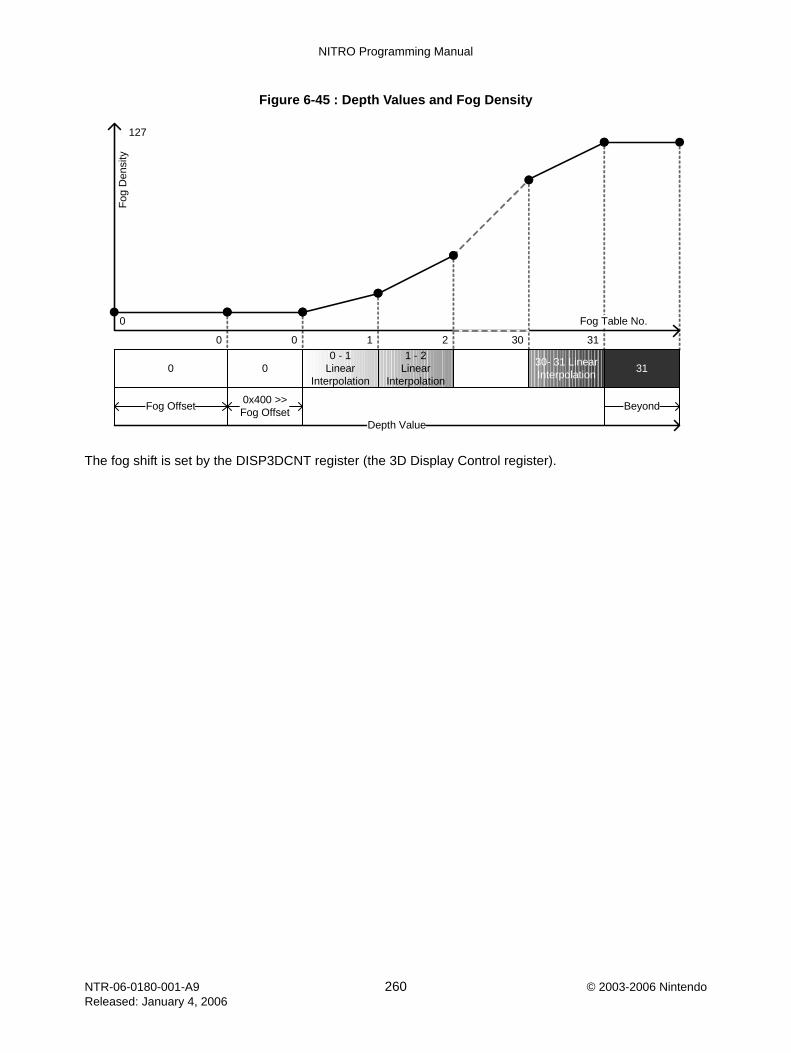
NITRO Programming Manual
Figure 6-45 : Depth Values and Fog Density
The fog shift is set by the DISP3DCNT register (the 3D Display Control register).
Fog Offset 0x400 >>Fog Offset Beyond
0
127Fo
g D
ensi
ty
Depth Value
Fog Table No.
0 1 2 30 31
00 - 1
Linear Interpolation
1 - 2Linear
Interpolation0 3130- 31 Linear
Interpolation
0
NTR-06-0180-001-A9 260 © 2003-2006 NintendoReleased: January 4, 2006
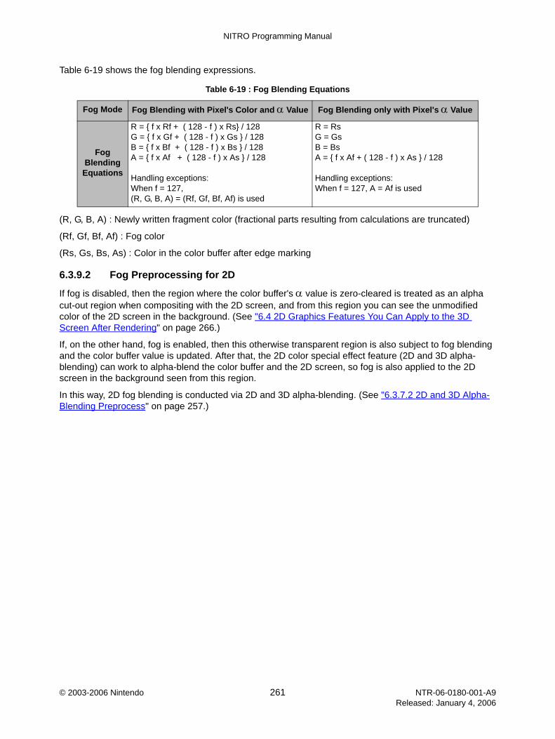
NITRO Programming Manual
Table 6-19 shows the fog blending expressions.
Table 6-19 : Fog Blending Equations
(R, G, B, A) : Newly written fragment color (fractional parts resulting from calculations are truncated)
(Rf, Gf, Bf, Af) : Fog color
(Rs, Gs, Bs, As) : Color in the color buffer after edge marking
6.3.9.2 Fog Preprocessing for 2D
If fog is disabled, then the region where the color buffer's α value is zero-cleared is treated as an alpha cut-out region when compositing with the 2D screen, and from this region you can see the unmodified color of the 2D screen in the background. (See "6.4 2D Graphics Features You Can Apply to the 3D Screen After Rendering" on page 266.)
If, on the other hand, fog is enabled, then this otherwise transparent region is also subject to fog blending and the color buffer value is updated. After that, the 2D color special effect feature (2D and 3D alpha-blending) can work to alpha-blend the color buffer and the 2D screen, so fog is also applied to the 2D screen in the background seen from this region.
In this way, 2D fog blending is conducted via 2D and 3D alpha-blending. (See "6.3.7.2 2D and 3D Alpha-Blending Preprocess" on page 257.)
Fog Mode Fog Blending with Pixel's Color and α Value Fog Blending only with Pixel's α Value
Fog Blending Equations
R = { f x Rf + ( 128 - f ) x Rs} / 128G = { f x Gf + ( 128 - f ) x Gs } / 128 B = { f x Bf + ( 128 - f ) x Bs } / 128A = { f x Af + ( 128 - f ) x As } / 128
Handling exceptions:When f = 127,(R, G, B, A) = (Rf, Gf, Bf, Af) is used
R = RsG = GsB = BsA = { f x Af + ( 128 - f ) x As } / 128
Handling exceptions:When f = 127, A = Af is used
© 2003-2006 Nintendo 261 NTR-06-0180-001-A9Released: January 4, 2006
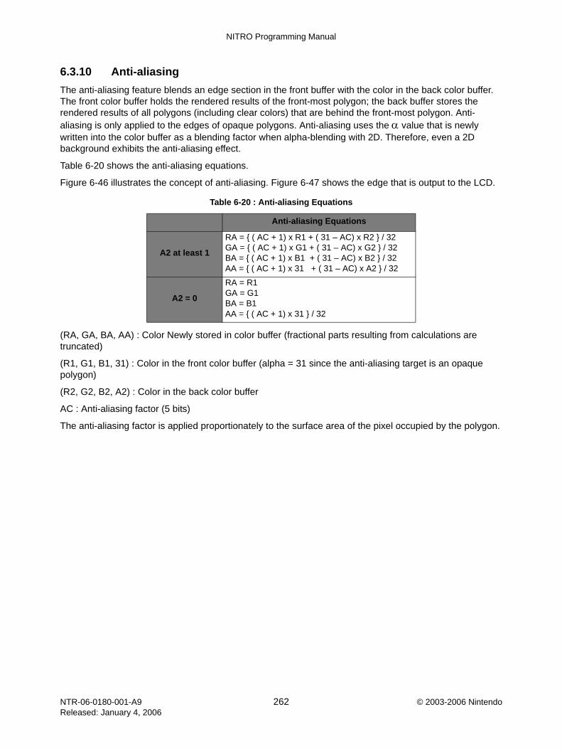
NITRO Programming Manual
6.3.10 Anti-aliasingThe anti-aliasing feature blends an edge section in the front buffer with the color in the back color buffer. The front color buffer holds the rendered results of the front-most polygon; the back buffer stores the rendered results of all polygons (including clear colors) that are behind the front-most polygon. Anti-aliasing is only applied to the edges of opaque polygons. Anti-aliasing uses the α value that is newly written into the color buffer as a blending factor when alpha-blending with 2D. Therefore, even a 2D background exhibits the anti-aliasing effect.
Table 6-20 shows the anti-aliasing equations.
Figure 6-46 illustrates the concept of anti-aliasing. Figure 6-47 shows the edge that is output to the LCD.
Table 6-20 : Anti-aliasing Equations
(RA, GA, BA, AA) : Color Newly stored in color buffer (fractional parts resulting from calculations are truncated)
(R1, G1, B1, 31) : Color in the front color buffer (alpha = 31 since the anti-aliasing target is an opaque polygon)
(R2, G2, B2, A2) : Color in the back color buffer
AC : Anti-aliasing factor (5 bits)
The anti-aliasing factor is applied proportionately to the surface area of the pixel occupied by the polygon.
Anti-aliasing Equations
A2 at least 1
RA = { ( AC + 1) x R1 + ( 31 – AC) x R2 } / 32GA = { ( AC + 1) x G1 + ( 31 – AC) x G2 } / 32BA = { ( AC + 1) x B1 + ( 31 – AC) x B2 } / 32AA = { ( AC + 1) x 31 + ( 31 – AC) x A2 } / 32
A2 = 0
RA = R1GA = G1BA = B1AA = { ( AC + 1) x 31 } / 32
NTR-06-0180-001-A9 262 © 2003-2006 NintendoReleased: January 4, 2006
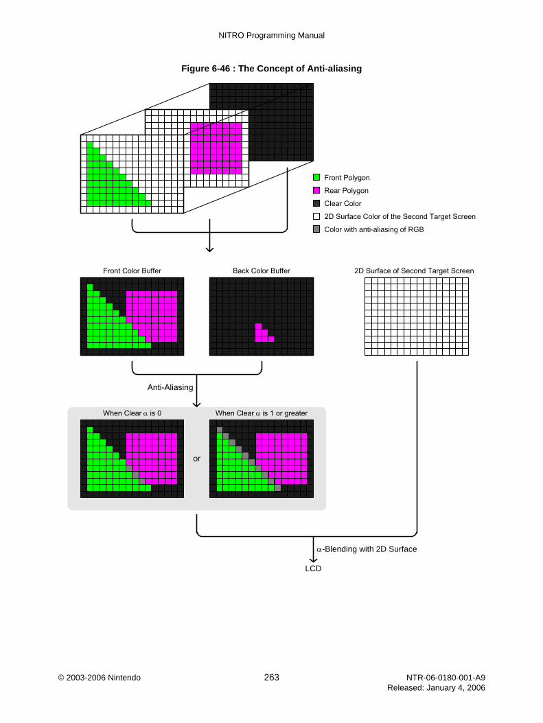
NITRO Programming Manual
Figure 6-46 : The Concept of Anti-aliasing
Anti-Aliasing
α-Blending with 2D Surface
LCD
Front Color Buffer Back Color Buffer
Clear Color
Front Polygon
Rear Polygon
2D Surface Color of the Second Target Screen
Color with anti-aliasing of RGB
2D Surface of Second Target Screen
When Clear α is 0 When Clear α is 1 or greater
or
© 2003-2006 Nintendo 263 NTR-06-0180-001-A9Released: January 4, 2006
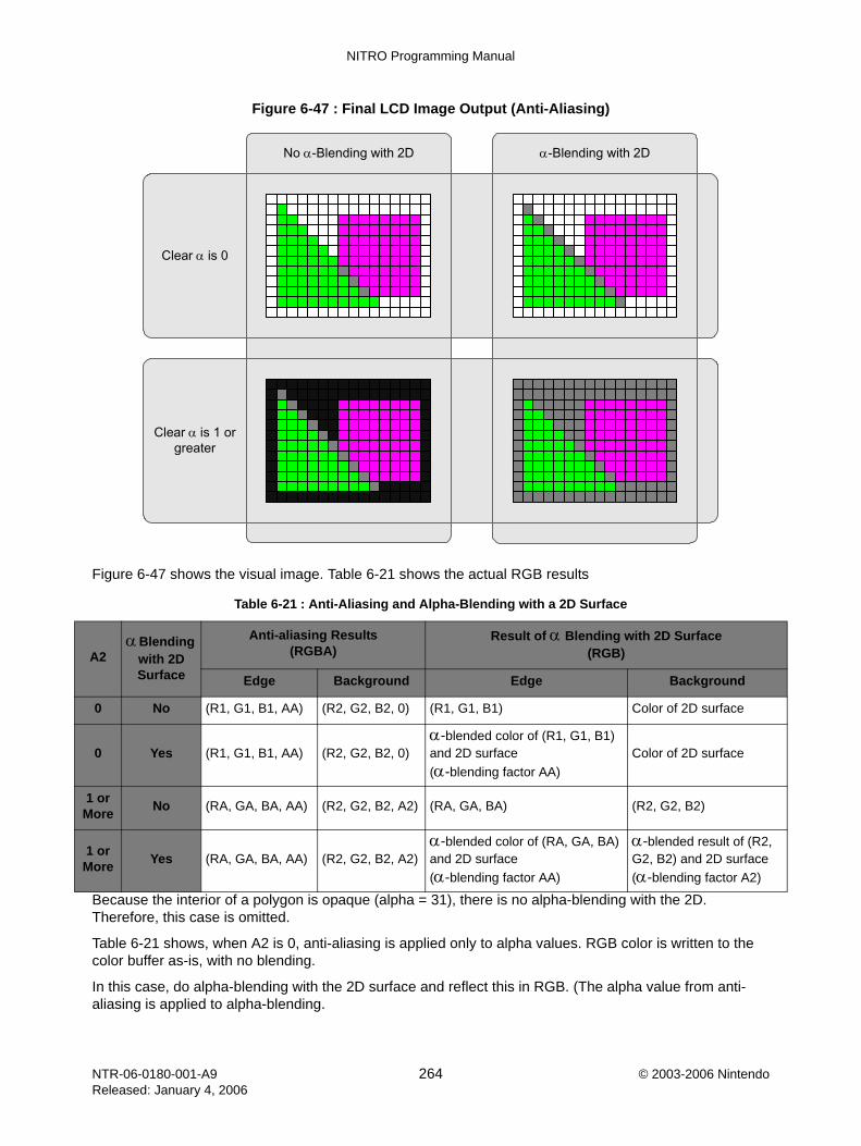
NITRO Programming Manual
Figure 6-47 : Final LCD Image Output (Anti-Aliasing)
Figure 6-47 shows the visual image. Table 6-21 shows the actual RGB results
Table 6-21 : Anti-Aliasing and Alpha-Blending with a 2D Surface
Because the interior of a polygon is opaque (alpha = 31), there is no alpha-blending with the 2D. Therefore, this case is omitted.
Table 6-21 shows, when A2 is 0, anti-aliasing is applied only to alpha values. RGB color is written to the color buffer as-is, with no blending.
In this case, do alpha-blending with the 2D surface and reflect this in RGB. (The alpha value from anti-aliasing is applied to alpha-blending.
A2α Blending
with 2D Surface
Anti-aliasing Results(RGBA)
Result of α Blending with 2D Surface(RGB)
Edge Background Edge Background
0 No (R1, G1, B1, AA) (R2, G2, B2, 0) (R1, G1, B1) Color of 2D surface
0 Yes (R1, G1, B1, AA) (R2, G2, B2, 0)α-blended color of (R1, G1, B1) and 2D surface(α-blending factor AA)
Color of 2D surface
1 or More No (RA, GA, BA, AA) (R2, G2, B2, A2) (RA, GA, BA) (R2, G2, B2)
1 or More Yes (RA, GA, BA, AA) (R2, G2, B2, A2)
α-blended color of (RA, GA, BA) and 2D surface(α-blending factor AA)
α-blended result of (R2, G2, B2) and 2D surface(α-blending factor A2)
No α-Blending with 2D α-Blending with 2D
Clear α is 0
Clear α is 1 or greater
NTR-06-0180-001-A9 264 © 2003-2006 NintendoReleased: January 4, 2006
NITRO Programming Manual
6.3.11 Status
Rendered Line Count RegisterName: RDLINES_COUNT Address: 0x04000320 Attribute: R Initial value: 0x0000
• RENDERED_LINES_MIN[d05–d00] : Minimum value for number of rendered lines (0–46)
Use this to check the minimum number of lines in the color buffer during display of the previous frame. This register is updated during every V cycle. The color buffer holds 48 lines, but 2 lines are the current buffer, so the largest count-value for this register is 46. You cannot confirm from this value whether or not lines have overflowed, but you can determine the risk of this happening. To determine whether or not lines have overflowed, check the Color Buffer Underflow Flag of the 3D Display Control register (DISP3DCNT).
Note: When the counter hits 0, there is a risk that the Rendering Engine will fail to draw lines (that is, lines will overflow). When the counter approaches 0, reduce the load on the Rendering Engine by, for example, reducing the number of polygons sent to the Geometry Engine.
A Comparison of Rendering Buffer Methods• Normal frame-buffer method
In this method, there are two or three frame buffers for rendering and display, and the buffers are swapped during the V-Blank period immediately after drawing is completed. If there are more rendering polygons and pixels than the rendering engine can process, the frame rate drops due to rendering delays.
• The FIFO line buffer method adopted by NITRO
In this method, drawing and display involve the same FIFO. This FIFO has the capacity to hold 48 lines of color data. During display, data is read from FIFO in sync with the timing of the LCD. Data for the horizontal direction is read with the dot clock, while data for the vertical direction is read in the horizontal scanning interval (355 dot clocks). If there are more polygons and pixels for the line to be drawn than the Rendering Engine can process, then the display is corrupted because the Rendering Engine could not render it in time.
RENDERED_LINES_MINMinimum value for number of rendered lines
15 8 7 5 0
© 2003-2006 Nintendo 265 NTR-06-0180-001-A9Released: January 4, 2006

NITRO Programming Manual
6.4 2D Graphics Features You Can Apply to the 3D Screen After RenderingIn NITRO, the 3D screen is displayed as BG0 after it has been rendered, rather than being displayed directly on the LCD. This enables certain 2D graphic features to also be applied and displayed on the LCD. To read the basic specifications for 2D graphics see "5 2D Graphics" on page 73.
6.4.1 Raster scrollUnlike 2D screens, 3D screens cannot be scrolled vertically. However they can be scrolled horizontally.
BG0 Offset Settings RegisterName: BG0OFS Address: 0x04000010 Attribute: W Initial value: 0x0000
Signed fixed-point number (sign + 8-bit integer)
• H[d08–d00] : H offset
Changes the starting position of display in the horizontal direction.
Unlike for 2D screens, d08 here is the sign bit, and the offset value can be set in the range of -256 to +256.
Portions of the display screen that go beyond the screen because of horizontal scrolling become transparent. (See Figure 6-48.)
Figure 6-48 : H Offset for a 3D Surface
6.4.2 Order of Display Priority With 2D Screen
BG0 Control RegisterName: BG0CNT (x=0, 1) Address: 0x04000008 Attribute: R / W Initial value: 0x0000
By adjusting the display priority you can place the 2D screen either in front or behind the 3D screen.
See the diagram in "5.9 Display Priority" on page 151.
SH INTEGER_HH Offset
15 8 7 0
H Offset
Transparent Display
Display Image
3D BG0 Screen
Order of Priority
15 8 7 1 0
NTR-06-0180-001-A9 266 © 2003-2006 NintendoReleased: January 4, 2006

NITRO Programming Manual
6.4.3 WindowsYou can apply windows to BG0 of the 3D screen.
Window Position Settings RegisterName: WINxH (x=0, 1) Address: 0x04000040, 0x04000042 Attribute: W Initial value: 0x0000
Name: WINxV (x=0, 1) Address: 0x04000044, 0x04000046 Attribute: W Initial value: 0x0000
Window Inside Control RegisterName: WININ Address: 0x04000048 Attribute: R / W Initial value: 0x0000
Window Outside Control RegisterName: WINOUT Address: 0x0400004A Attribute: R / W Initial value: 0x0000
If the 3D screen has highest priority, then α-blending is always enabled, regardless of the setting for the Window Control register's color effect enable flag.
Window's upper-left X coordinate Window's lower-right X coordinate
15 8 7 0
Window's upper-left Y coordinate Window's lower-right Y coordinate
15 8 7 0
EFCT OBJ BG3 BG2 BG1 BG0 EFCT OBJ BG3 BG2 BG1 BG0Window 1 Inside Window 0 Inside
15 8 7 0
EFCT OBJ BG3 BG2 BG1 BG0 EFCT OBJ BG3 BG2 BG1 BG0OBJ Window Inside Window (0, 1 and OBJ Window) Outside
15 8 7 0
© 2003-2006 Nintendo 267 NTR-06-0180-001-A9Released: January 4, 2006

NITRO Programming Manual
6.4.4 Color EffectsFor details on each register parameter see the Color Special Effects Register below.
6.4.4.1 Alpha-Blending with the 2D Screen
The α-blending feature of the 2D color effects is used for post-processing after the 2D and 3D α-blending process and the 2D fog process. To read about preprocessing, see "6.3.7.2 2D and 3D Alpha-Blending Preprocess" on page 257 and "6.3.9.2 Fog Preprocessing for 2D" on page 261.
Color Effect Control RegisterName: BLDCNT Address: 0x04000050 Attribute: R / W Initial value: 0x0000
• [d07–d06] : Selected effect
Perform alpha-blending by setting [d07] to 0 and [d06] to 1.
The process involved when alpha-blending the 3D screen and the 2D screen differs depending on the relative priority of the two screens. When the 2D screen is the 1st target screen, the value set in the BLDALPHA register is used for alpha-blending, as per the specifications. However, when the 3D screen is the 1st target screen, then alpha-blending with the 2nd target screen is performed using the alpha value that is being rendered to the color buffer (that is, alpha-blending is done in units of pixels).
Note: Any part with a color buffer alpha-value of 0 is handled in the same way as a 2D cut-out region and thus is not subjected to alpha-blending. Any part with a color buffer alpha-value of 1 or more is subjected to alpha-blending.
Color Special Effect / Alpha-Blending Factors RegisterName: BLDALPHA Address: 0x04000052 Attribute: R / W Initial value: 0x0000
The factors used for the alpha-blending process are set by EVA and EVB in the BLDALPHA register. (EVA, EVB values that are 16 or above are treated as 16.)
BD OBJ BG3 BG2 BG1 BG0 0 1 BD OBJ BG3 BG2 BG1 BG0Second Target Screen Selected Effect First Target Screen
15 13 8 7 6 5 0
EVB EVA
15 12 8 7 4 0
NTR-06-0180-001-A9 268 © 2003-2006 NintendoReleased: January 4, 2006

NITRO Programming Manual
6.4.4.2 Shininess Up/Down
Color Effect Control RegisterName: BLDCNT Address: 0x04000050 Attribute: R / W Initial value: 0x0000
• [d07–d06] : Color special effect selection
Perform a process to change the shininess by setting [d07] to 1.
When [d06] is set to 0, the shininess is increased. When [d06] is set to 1, the shininess is decreased.
All zeros must be set for the 2nd target screen.
Color Special Effect / Change Shininess Factor RegisterName: BLDY Address: 0x04000054 Attribute: W Initial value: 0x0000
The factor used for changing the shininess is set by EVY in the BLDY register. (EVY values that are 16 or above are treated as 16.)
BD OBJ BG3 BG2 BG1 BG0 1 BD OBJ BG3 BG2 BG1 BG0Second Target Screen Selected Effect First Target Screen
15 13 8 7 6 5 0
EVY
15 8 7 0
© 2003-2006 Nintendo 269 NTR-06-0180-001-A9Released: January 4, 2006
NITRO Programming Manual
NTR-06-0180-001-A9 270 © 2003-2006 NintendoReleased: January 4, 2006
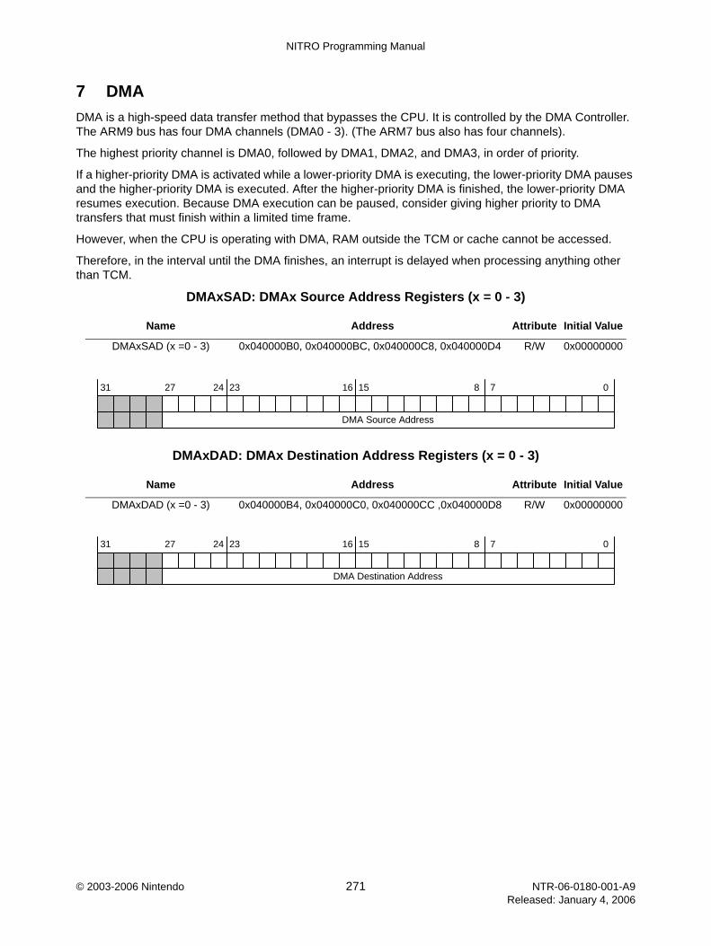
NITRO Programming Manual
7 DMADMA is a high-speed data transfer method that bypasses the CPU. It is controlled by the DMA Controller. The ARM9 bus has four DMA channels (DMA0 - 3). (The ARM7 bus also has four channels).
The highest priority channel is DMA0, followed by DMA1, DMA2, and DMA3, in order of priority.
If a higher-priority DMA is activated while a lower-priority DMA is executing, the lower-priority DMA pauses and the higher-priority DMA is executed. After the higher-priority DMA is finished, the lower-priority DMA resumes execution. Because DMA execution can be paused, consider giving higher priority to DMA transfers that must finish within a limited time frame.
However, when the CPU is operating with DMA, RAM outside the TCM or cache cannot be accessed.
Therefore, in the interval until the DMA finishes, an interrupt is delayed when processing anything other than TCM.
DMAxSAD: DMAx Source Address Registers (x = 0 - 3)
DMAxDAD: DMAx Destination Address Registers (x = 0 - 3)
Name Address Attribute Initial Value
DMAxSAD (x =0 - 3) 0x040000B0, 0x040000BC, 0x040000C8, 0x040000D4 R/W 0x00000000
Name Address Attribute Initial Value
DMAxDAD (x =0 - 3) 0x040000B4, 0x040000C0, 0x040000CC ,0x040000D8 R/W 0x00000000
DMA Source Address
31 27 24 23 16 15 8 7 0
DMA Destination Address
31 27 24 23 16 15 8 7 0
© 2003-2006 Nintendo 271 NTR-06-0180-001-A9Released: January 4, 2006
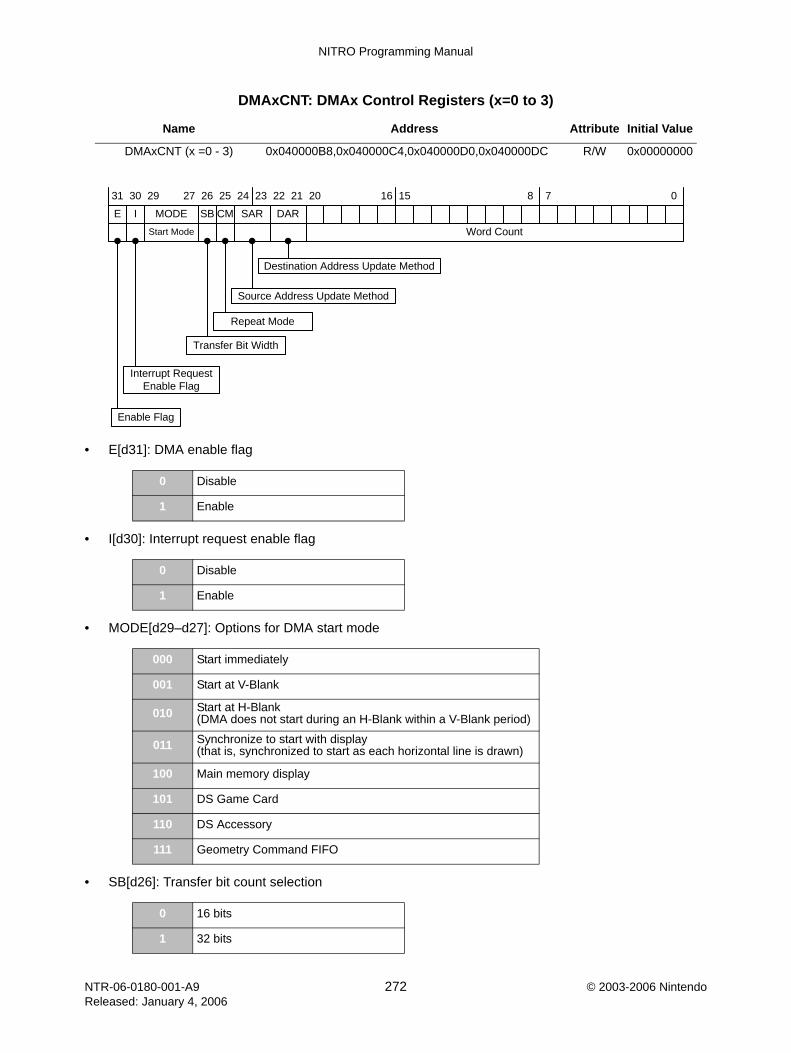
NITRO Programming Manual
DMAxCNT: DMAx Control Registers (x=0 to 3)
• E[d31]: DMA enable flag
• I[d30]: Interrupt request enable flag
• MODE[d29–d27]: Options for DMA start mode
• SB[d26]: Transfer bit count selection
Name Address Attribute Initial Value
DMAxCNT (x =0 - 3) 0x040000B8,0x040000C4,0x040000D0,0x040000DC R/W 0x00000000
0 Disable
1 Enable
0 Disable
1 Enable
000 Start immediately
001 Start at V-Blank
010 Start at H-Blank (DMA does not start during an H-Blank within a V-Blank period)
011 Synchronize to start with display (that is, synchronized to start as each horizontal line is drawn)
100 Main memory display
101 DS Game Card
110 DS Accessory
111 Geometry Command FIFO
0 16 bits
1 32 bits
E I MODE SB CM SAR DARStart Mode Word Count
31 30 29 27 26 25 24 23 22 21 16 15 8 7 0
Enable Flag
Interrupt Request Enable Flag
Transfer Bit Width
Repeat Mode
Source Address Update Method
Destination Address Update Method
20
NTR-06-0180-001-A9 272 © 2003-2006 NintendoReleased: January 4, 2006
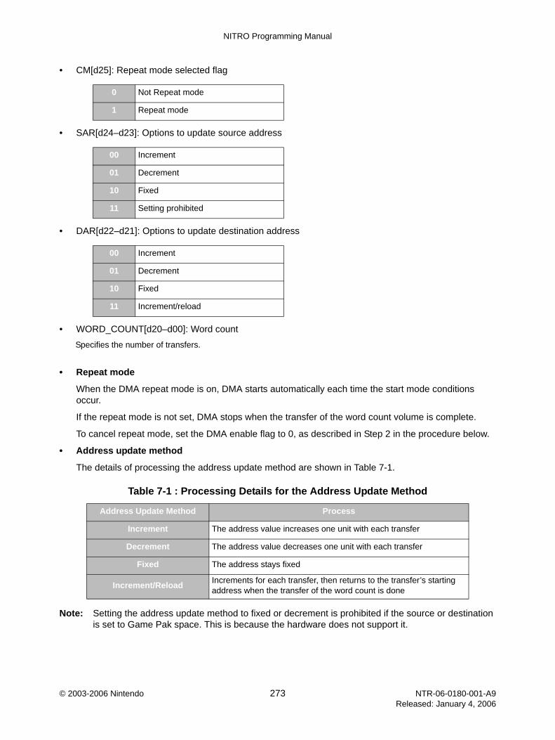
NITRO Programming Manual
• CM[d25]: Repeat mode selected flag
• SAR[d24–d23]: Options to update source address
• DAR[d22–d21]: Options to update destination address
• WORD_COUNT[d20–d00]: Word countSpecifies the number of transfers.
• Repeat mode
When the DMA repeat mode is on, DMA starts automatically each time the start mode conditions occur.
If the repeat mode is not set, DMA stops when the transfer of the word count volume is complete.
To cancel repeat mode, set the DMA enable flag to 0, as described in Step 2 in the procedure below.
• Address update method
The details of processing the address update method are shown in Table 7-1.
Table 7-1 : Processing Details for the Address Update Method
Note: Setting the address update method to fixed or decrement is prohibited if the source or destination is set to Game Pak space. This is because the hardware does not support it.
0 Not Repeat mode
1 Repeat mode
00 Increment
01 Decrement
10 Fixed
11 Setting prohibited
00 Increment
01 Decrement
10 Fixed
11 Increment/reload
Address Update Method Process
Increment The address value increases one unit with each transfer
Decrement The address value decreases one unit with each transfer
Fixed The address stays fixed
Increment/Reload Increments for each transfer, then returns to the transfer’s starting address when the transfer of the word count is done
© 2003-2006 Nintendo 273 NTR-06-0180-001-A9Released: January 4, 2006

NITRO Programming Manual
• DMA Start Mode
Main Memory Display Start Mode
Do not set the DMA source address to any memory region outside of main memory in Main Memory Display Mode. Also, be sure to set the transfer bit mode to 32-bit and the word count value to 4.
Geometry Command FIFO Start Mode
When the Geometry Command FIFO becomes less than half full, DMA starts and 112 words (see the procedure below) are transferred. The process repeats until the volume transferred reaches the word count value.
Note: If commands have been packed, the number of words sent in each repetition equals the num-ber of words before unpacking.
• Procedures to Start and Stop DMA
1. When starting DMA
A delay of 2 cycles of the system clock (33.514 Mhz) occurs from the time the DMA enable flag is set until the time DMA starts. If any of the DMA-related registers are accessed during this period, DMA might not operate correctly. To prevent a DMA problem during this period, run another process, such as inserting a dummy Load command. (The main processor executes a Load command in ½ cycle of the system clock, so you would need to insert two or more Load commands to the same register.)
2. When stopping DMA
DMA begins when the signal that serves as the start trigger is issued. If the CPU disables DMA at the same time the start trigger is issued, DMA could lock up. Therefore, be sure to disable DMA at least 4 cycles after the start trigger.1. When the DMA repeat feature is off
Because the DMA stops automatically after it is executed once, do not forcibly clear the DMA enable flag. Instead, wait for the flag to become 0.
2. When the DMA repeat feature is on
Be sure to clear the DMA enable flag with the CPU at least 4 cycles after the signal that serves as the DMA start trigger. For example, you can safely stop DMA using the interrupt generated when DMA ends, clearing the DMA enable flag before the next start trigger is issued.
If you cannot use this method, then stop DMA using the procedure described below.3. Stopping DMA in H-Blank or V-Blank auto-start mode
During a V-Blank period, DMA is stopped and the start trigger is not issued, so you can safely clear the DMA enable flag at that time. If you cannot use this method, follow the procedure below:
Step 1: Write 16 bits to the DMA control register (see Table 7-2).
Table 7-2 : Register Configuration (Step 1)
Setting Content
DMA Enable Flag 1 (Enable)
DMA Start Timing 00 (Start Immediately mode)
DMA Repeat Mode 0 (Disable Repeat Mode)
Other Bits Do not change
NTR-06-0180-001-A9 274 © 2003-2006 NintendoReleased: January 4, 2006
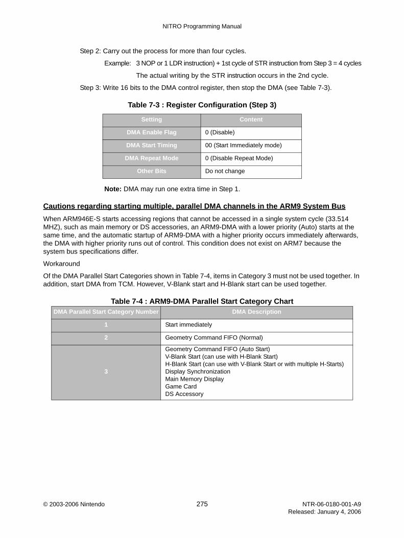
NITRO Programming Manual
Step 2: Carry out the process for more than four cycles.
Example: 3 NOP or 1 LDR instruction) + 1st cycle of STR instruction from Step 3 = 4 cycles
The actual writing by the STR instruction occurs in the 2nd cycle.
Step 3: Write 16 bits to the DMA control register, then stop the DMA (see Table 7-3).
Table 7-3 : Register Configuration (Step 3)
Note: DMA may run one extra time in Step 1.
Cautions regarding starting multiple, parallel DMA channels in the ARM9 System BusWhen ARM946E-S starts accessing regions that cannot be accessed in a single system cycle (33.514 MHZ), such as main memory or DS accessories, an ARM9-DMA with a lower priority (Auto) starts at the same time, and the automatic startup of ARM9-DMA with a higher priority occurs immediately afterwards, the DMA with higher priority runs out of control. This condition does not exist on ARM7 because the system bus specifications differ.
Workaround
Of the DMA Parallel Start Categories shown in Table 7-4, items in Category 3 must not be used together. In addition, start DMA from TCM. However, V-Blank start and H-Blank start can be used together.
Table 7-4 : ARM9-DMA Parallel Start Category Chart
Setting Content
DMA Enable Flag 0 (Disable)
DMA Start Timing 00 (Start Immediately mode)
DMA Repeat Mode 0 (Disable Repeat Mode)
Other Bits Do not change
DMA Parallel Start Category Number DMA Description
1 Start immediately
2 Geometry Command FIFO (Normal)
3
Geometry Command FIFO (Auto Start)V-Blank Start (can use with H-Blank Start)H-Blank Start (can use with V-Blank Start or with multiple H-Starts)Display SynchronizationMain Memory DisplayGame CardDS Accessory
© 2003-2006 Nintendo 275 NTR-06-0180-001-A9Released: January 4, 2006

NITRO Programming Manual
NTR-06-0180-001-A9 276 © 2003-2006 NintendoReleased: January 4, 2006
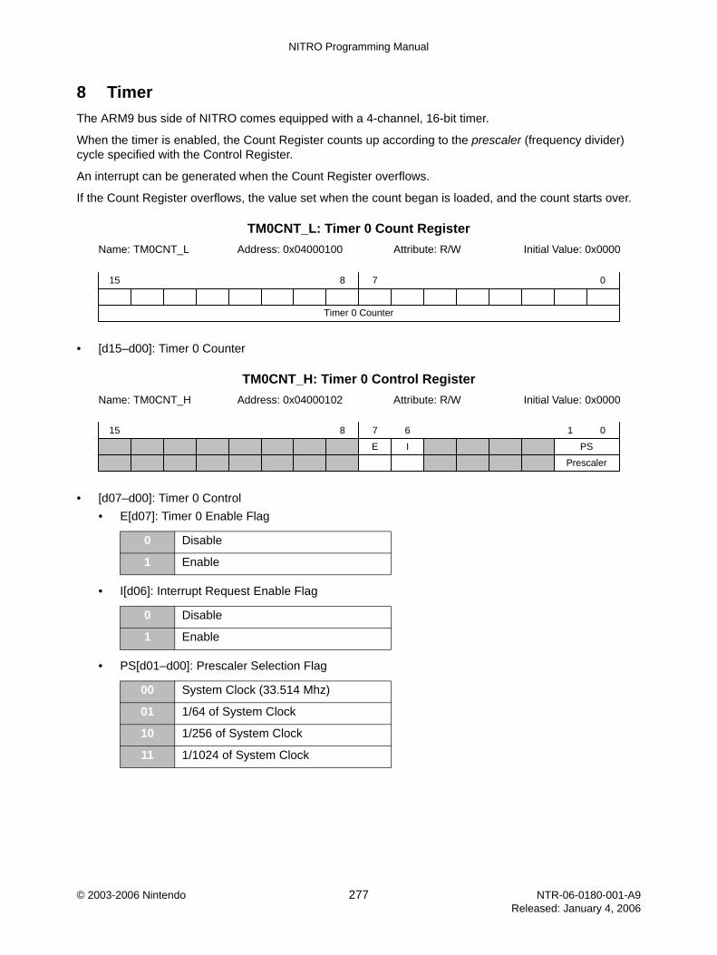
NITRO Programming Manual
8 TimerThe ARM9 bus side of NITRO comes equipped with a 4-channel, 16-bit timer.
When the timer is enabled, the Count Register counts up according to the prescaler (frequency divider) cycle specified with the Control Register.
An interrupt can be generated when the Count Register overflows.
If the Count Register overflows, the value set when the count began is loaded, and the count starts over.
TM0CNT_L: Timer 0 Count RegisterName: TM0CNT_L Address: 0x04000100 Attribute: R/W Initial Value: 0x0000
• [d15–d00]: Timer 0 Counter
TM0CNT_H: Timer 0 Control RegisterName: TM0CNT_H Address: 0x04000102 Attribute: R/W Initial Value: 0x0000
• [d07–d00]: Timer 0 Control• E[d07]: Timer 0 Enable Flag
• I[d06]: Interrupt Request Enable Flag
• PS[d01–d00]: Prescaler Selection Flag
0 Disable
1 Enable
0 Disable
1 Enable
00 System Clock (33.514 Mhz)
01 1/64 of System Clock
10 1/256 of System Clock
11 1/1024 of System Clock
Timer 0 Counter
15 8 7 0
E I PS
Prescaler
15 8 7 6 1 0
© 2003-2006 Nintendo 277 NTR-06-0180-001-A9Released: January 4, 2006

NITRO Programming Manual
TMxCNT_L: Timer x Count Register (x = 1 – 3)Name: TMxCNT_L (x =1–3) Address: 0x04000104,0x04000108,0x0400010C Attribute: R/W Initial Value: 0x0000
• [d15–d00]: Timer x Counter
TMxCNT_H: Timer x Control Register (x = 1 – 3)Name: TMxCNT_H (x =1–3) Address: 0x04000106,0x0400010A,0x0400010E Attribute: R/W Initial Value: 0x0000
• [d07–d00]: Timer x Control• E[d07]: Timer x Enable Flag
• I[d06]: Interrupt Request Enable Flag
• CH[d02]: Multistage Counter Selection Flag
• PS[d01–d00]: Prescaler Selection Flag
0 Disable
1 Enable
0 Disable
1 Enable
0 According to Prescaler setting
1 Counts up when timer (x-1) overflows regardless of Prescaler setting
00 System Clock (33.514Mhz)
01 1/64 of System Clock
10 1/256 of System Clock
11 1/1024 of System Clock
Timer x Counter
15 8 7 0
E I CH PSMulti-Stage Prescaler
15 8 7 6 2 1 0
NTR-06-0180-001-A9 278 © 2003-2006 NintendoReleased: January 4, 2006

NITRO Programming Manual
9 InterruptsThis chapter describes the hardware interrupts for the ARM9 main processor.
When an interrupt request signal occurs from each piece of hardware, the bit that supports the interrupt request register is set and, if interrupts are enabled, the CPU is informed of the interrupt occurrence.
Each hardware interrupt request signal can be disabled individually via the interrupt enable register.
9.1 The Interrupt Master Enable RegisterThis register can disable registers as a whole and it configures whether to disable all registers or to enable the interrupt enable register settings.
IME: Interrupt Master Enable RegisterName: IME Address: 0x04000208 Attribute: R/W Initial Value: 0x0000
• IME[d00]: Interrupt Master Enable Flag
0 Disable all interrupts
1 Enable the Interrupt Enable Register settings
IME
15 8 7 0
© 2003-2006 Nintendo 279 NTR-06-0180-001-A9Released: January 4, 2006

NITRO Programming Manual
9.2 The Interrupt Enable RegisterEach hardware interrupt request can be disabled individually.
Setting each bit enables interrupt requests from the corresponding hardware. Conversely, interrupt requests from corresponding hardware are disabled when the bit is reset.
IE: Interrupt Enable RegisterName: IE Address: 0x04000210 Attribute: R/W Initial Value: 0x00000000
• GF[d21]: Geometry Command FIFO Interrupt Permission FlagFor more information, see "6.2.16 Status" on page 218.
• MI[d20]: NITRO Card IREQ_MC Interrupt Permission Flag• MC[d19]: NITRO Card Data Transfer Completion Interrupt Permission Flag• IFN[d18]: ARM9 – ARM7 FIFO Not Empty Interrupt Permission Flag• IFE[d17]: ARM9 – ARM7 FIFO Empty Interrupt Permission Flag• A7[d16]: ARM7 Interrupt Permission Flag• I/D[d13]: DS Accessory IREQ/DREQ Interrupt Permission Flag• K[d12]: Key Interrupt Permission Flag
For more information, see "12.2 Interrupt Handling for Key Input" on page 296.• D3[d11]: DMA3 Interrupt Permission Flag• D2[d10]: DMA2 Interrupt Permission Flag• D1[d09]: DMA1 Interrupt Permission Flag• D0[d08]: DMA0 Interrupt Permission Flag
For more information, see Chapter 7.• T3[d06]: Timer 3 Interrupt Permission Flag• T2[d05]: Timer 2 Interrupt Permission Flag• T1[d04]: Timer 1 Interrupt Permission Flag• T0[d03]: Timer 0 Interrupt Permission Flag
For more information, see Chapter 8.• VE[d02]: V-Counter Match Interrupt Permission Flag• HB[d01]: H-Blank Interrupt Permission Flag• VB[d00]: V-Blank Interrupt Permission Flag
For more information, see "4.3 Display Status" on page 51.
GF MI MC IFN IFE A7 I/D K D3 D2 D1 D0 T3 T2 T1 T0 VE HB VB
DMA Timer LCD
31 24 23 21 20 19 18 17 16 15 13 12 11 8 7 6 3 2 0
Geometry Command FIFO
Game Card
ARM9 - ARM7 FIFO
ARM7DS Accessory
Key
NTR-06-0180-001-A9 280 © 2003-2006 NintendoReleased: January 4, 2006

NITRO Programming Manual
9.3 The Interrupt Request RegisterWhen an interrupt request from a hardware component occurs, the corresponding bit for the hardware component is set in the interrupt request register.
Also, if 1 is written to the bit where the interrupt request flag is set, the interrupt request flag is reset.
IF: Interrupt Request RegisterName: IF Address: 0x04000214 Attribute: R/W Initial Value: 0x00000000
• GF[d21]: Geometry Command FIFO Interrupt Request FlagFor more information, see "6.2.16 Status" on page 218.
• MI[d20]: NITRO Card IREQ_MC Interrupt Request Flag• MC[d19]: NITRO Card Data Transfer Completion Interrupt Request Flag• IFN[d18]: ARM9 – ARM7 FIFO Not Empty Interrupt Request Flag• IFE[d17]: ARM9 – ARM7 FIFO Empty Interrupt Request Flag• A7[d16]: ARM7 Interrupt Request Flag• I/D[d13]: DS Accessory IREQ/DREQ Interrupt Request Flag• K[d12]: Key Interrupt Request Flag
For more information, see "12.2 Interrupt Handling for Key Input" on page 296.• D3[d11]: DMA3 Interrupt Request Flag• D2[d10]: DMA2 Interrupt Request Flag• D1[d09]: DMA1 Interrupt Request Flag• D0[d08]: DMA0 Interrupt Request Flag
For more information, see Chapter 7.• T3[d06]: Timer 3 Interrupt Request Flag• T2[d05]: Timer 2 Interrupt Request Flag• T1[d04]: Timer 1 Interrupt Request Flag• T0[d03]: Timer 0 Interrupt Request Flag
For more information, see Chapter 8.• VE[d02]: V-Counter Match Interrupt Request Flag• HB[d01]: H-Blank Interrupt Request Flag• VB[d00]: V-Blank Interrupt Request Flag
For more information, see "4.3 Display Status" on page 51.
GF MI MC IFN IFE A7 I/D K D3 D2 D1 D0 T3 T2 T1 T0 VE HB VB
DMA Timer LCD
31 24 23 21 20 19 18 17 16 15 13 12 11 8 7 6 3 2 0
Geometry Command FIFO
Game Card
ARM9 - ARM7 FIFO
ARM7DS Accessory
Key
© 2003-2006 Nintendo 281 NTR-06-0180-001-A9Released: January 4, 2006
NITRO Programming Manual
9.4 Interrupt Cautions
9.4.1 Clearing IME and IEEven while the command to clear all flags in the IME and IE registers is executing, relevant interrupts are generated.
When clearing the IE flags, be sure to clear IME first to avoid inconsistencies in interrupt checks.
9.4.2 Multiple InterruptsIf clearing the IME and an interrupt occur at the same time, multiple interrupts are not accepted during that interrupt. Therefore, you must set the IME after clearing the IME during the interrupt routine.
9.4.3 Interrupt Delays During DMA OperationThe CPU cannot access RAM other than the TCM or cache RAM during DMA operations.
Therefore, during the interval until the DMA stops, the interrupt is delayed when performing interrupt handling on anything other than TCM.
9.4.4 Interrupts from ARM7The A7, IFE, and IFN interrupts are for use by the subprocessor and the subprocessor API for communications.
The subprocessor API does not operate properly if these interrupts are disabled or if the interrupt request is reset.
NTR-06-0180-001-A9 282 © 2003-2006 NintendoReleased: January 4, 2006
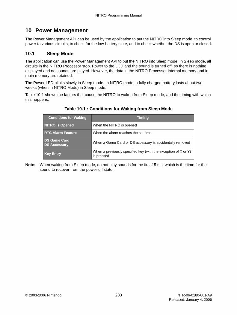
NITRO Programming Manual
10 Power ManagementThe Power Management API can be used by the application to put the NITRO into Sleep mode, to control power to various circuits, to check for the low-battery state, and to check whether the DS is open or closed.
10.1 Sleep ModeThe application can use the Power Management API to put the NITRO into Sleep mode. In Sleep mode, all circuits in the NITRO Processor stop. Power to the LCD and the sound is turned off, so there is nothing displayed and no sounds are played. However, the data in the NITRO Processor internal memory and in main memory are retained.
The Power LED blinks slowly in Sleep mode. In NITRO mode, a fully charged battery lasts about two weeks (when in NITRO Mode) in Sleep mode.
Table 10-1 shows the factors that cause the NITRO to waken from Sleep mode, and the timing with which this happens.
Table 10-1 : Conditions for Waking from Sleep Mode
Note: When waking from Sleep mode, do not play sounds for the first 15 ms, which is the time for the sound to recover from the power-off state.
Conditions for Waking Timing
NITRO Is Opened When the NITRO is opened
RTC Alarm Feature When the alarm reaches the set time
DS Game CardDS Accessory When a Game Card or DS accessory is accidentally removed
Key Entry When a previously specified key (with the exception of X or Y) is pressed
© 2003-2006 Nintendo 283 NTR-06-0180-001-A9Released: January 4, 2006
NITRO Programming Manual
10.2 Controlling Various Power SuppliesThe Power Management API can be used to control the power supply to the sound circuitry, LCD backlight, LCD, microphone, system, and graphics.
10.2.1 SoundThe power supply to the sound circuitry can be controlled using the Power Management API. When the application is not playing sounds, the Power Management API can be used to turn power off to the sound circuitry to reduce battery consumption.
Note: Do not play sounds for the first 15ms, which is the time it takes for the sound circuitry to recover from the power-off state.
10.2.2 LCD BacklightThe Power Management API can be used to control the power supply to the backlight of the upper screen and the backlight of the lower screen separately. When the application is using only one LCD screen, the power can be turned off to the screen that is not being used to reduce battery consumption.
When no game is being played and the system is not standing by for wireless, if you choose not to display on either LCD and to turn off power to the LCD backlight in consideration of battery life, we suggest that you move to Sleep Mode, which more effectively reduces power consumption.
10.2.3 LCDThe Power Management API can be used to control power supply to both the upper and lower screen LCDs. Furthermore, the LCD backlight can be turned off regardless of the LCD backlight settings. How-ever, the LCD backlight settings are preserved.
When there is no display on the LCD screen, such as when the application is waiting for wireless commu-nication, battery consumption can be controlled by turning of the power supply to the LCD.
When the system is not standing by for wireless, if you choose to turn off power to the LCD in consideration of battery life, we suggest that you move to Sleep Mode, which more effectively reduces power consump-tion.
Note: Although the power supply to the LCD can be directly controlled with the graphics power control register mentioned below, the LCD circuitry may be damaged according to when the LCD is turned ON/OFF. Therefore, directly changing the register value is prohibited. When manipulating the power supply to the LCD, always use the API.
When the LCD is turned OFF, the power supply to the sound amp is also turned off. Therefore the speaker will not function. However, sound will come from the headphones, because the head-phone amp is not effected.
10.2.4 MicrophoneWhen using the microphone, power must be turned on to the PMIC’s programmable gain amplifier (PGA). The Power Management API can be used to control power to the PGA.
Note: Do not use the microphone for 500 ms after power to the microphone is turned on.
10.2.5 SystemThe Power Management API can be used to turn off the NITRO’s system power (shut-down).
NTR-06-0180-001-A9 284 © 2003-2006 NintendoReleased: January 4, 2006

NITRO Programming Manual
10.2.6 GraphicsPower consumption can be reduced by: controlling the clock supply to the circuits of the geometry engine, the rendering engine, and the 2D graphics engine; and disabling circuits that are not being used.
Figure 10-1 : POWCNT: Graphics Power Control RegisterName: POWCNT Address: 0x04000304 Attribute: R/W Initial value: 0x0000
• 2DGB[d09] : 2D Graphics Engine B Enable Flag
Used to reduce power consumption when the 2D Graphics Engine B is not being used.
• GE[d03] : Geometry Engine Enable Flag
When the geometry engine is enabled, issue the SwapBuffers command once.
• RE[d02] : Rendering Engine Enable Flag
If the rendering engine is enabled, issue the SwapBuffers command once.
• 2DGA[d01] : 2D Graphics Engine A Enable Flag
Used to reduce power consumption when only 3D graphics are being used.
0 Disable
1 Enable
0 Disable
1 Enable
0 Disable
1 Enable
0 Disable
1 Enable
09 8 7 3 2 115DSEL 2DGB GE RE 2DGA LCDE
2D Graphics Engine A Enable Flag
Rendering Engine Enable Flag
Geometry Engine Enable Flag
2D Graphics Engine B Enable Flag
Enable Flag for both LCDs
© 2003-2006 Nintendo 285 NTR-06-0180-001-A9Released: January 4, 2006

NITRO Programming Manual
• LCDE[d00] : Enable Flag for Both LCDs (Use Prohibited)
When disabled, both the clock supply to the main and sub LCD controllers and the power supply to the main and sub LCDs are stopped.
Note: Use the API to enable/disable the LCDs. Be careful not to change this bit when writing data to other bits.
0 Disable
1 Enable
NTR-06-0180-001-A9 286 © 2003-2006 NintendoReleased: January 4, 2006

NITRO Programming Manual
The memory addresses and registers to which the clock signal is stopped when each flag is disabled:
• When the 2D Graphics Engine A is disabled:
0x04000008 - 0x0400004D
0x04000050 - 0x04000055
2D Graphics Engine A’s OAM and palette RAM
• When the 2D Graphics Engine B is disabled:
0x04001008 - 0x0400104d
0x04001050 - 0x04001055
2D Graphics Engine B’s OAM and palette RAM
• When the Geometry Engine is disabled:
0x04000400 - 0x04000473
0x04000480 - 0x040004AF
0x040004C0 - 0x040004D3
0x04000500 - 0x04000507
0x04000540 - 0x04000543
0x04000580 - 0x04000583
0x040005C0 - 0x040005CB
0x04000600 - 0x04000607
0x04000610 - 0x04000611
0x04000620 - 0x04000635
0x04000640 - 0x040006A3
• When the Rendering Engine is disabled:
0x04000320 - 0x04000321
0x04000330 - 0x04000341
0x04000350 - 0x0400035D
0x04000360 - 0x040003BF
Table 10-2 shows the behavior that occurs when there is access to memory and registers to which the clock signal has been stopped.
Table 10-2 : Access to Memory and Registers when Clock Signal Is Stopped
Write Read
Memory Invalid ALL zero
Registers Invalid Read-enabled
© 2003-2006 Nintendo 287 NTR-06-0180-001-A9Released: January 4, 2006
NITRO Programming Manual
10.3 Power Status
10.3.1 Low Battery StateWhen the remaining charge in the battery drops below 10-20%, the low battery state is entered and the Power LED becomes red. The Power Management API can be used to read the battery state data and check for the low-battery state (see Table 10-3). The amount of charge left in the battery when the power LED changes to red is only rough indication due to individual differences in the NITRO system, batteries, application, and environmental temperature.
Table 10-3 : Battery state data
Details about PMIC status data:
• Low Battery State Flag
0 : Battery still has a charge
1 : Battery is low
10.3.2 DS Open/Closed StateThe Power Management API can be used to read the status data shown in Table 10-4 to check whether the DS is open or closed.
Table 10-4 : DS Opened/Closed State Data
Details about DS open/closed status data:
• DS Opened/Closed State Flag
0 : DS is open
1 : DS is closed
Data Type Data Content
Battery State Low battery state flag (0 – 1)
Data Type Data Content
Device Opened/Closed State DS Opened/Closed State Flag (0 – 1)
NTR-06-0180-001-A9 288 © 2003-2006 NintendoReleased: January 4, 2006

NITRO Programming Manual
11 AcceleratorsNITRO contains both divider and square-root computation accelerators.
11.1 DividerShown below are the Divider Data setting register for the Divider and the Control Register that specifies the Divider mode and indicates the Divider state.
Divider Data (Numerator, Denominator, Quotient, Remainder) Registers
Signed integer (sign + 63-bit integer part)
DIVCNT: Divider Control RegisterName: DIVCNT Address: 0x04000280 Attribute: R/W Initial value: 0x0000
• BUSY[d15]: Busy Flag
• DIV0[d14]: Divide by zero error flag
Name Address Attribute Initial Value Comment
DIV_NUMER 0x04000290 R/W 0x00000000_00000000 Numerator
DIV_DENOM 0x04000298 R/W 0x00000000_00000000 Denominator
DIV_RESULT 0x040002a0 R/W 0x00000000_00000000 Quotient
DIVREM_RESULT 0x040002a8 R/W 0x00000000_00000000 Remainder
0 Divider is ready
1 Divider is busy
0 There is no divide by zero error
1 There is a divide by zero error
Divider Data Lower Word
31 24 23 16 15 8 7 0
Divider Data Upper Word
31 24 23 16 15 8 7 0
BUSY DIV0 MODE
Busy Division by Zero Division Mode
15 14 8 7 1 0
© 2003-2006 Nintendo 289 NTR-06-0180-001-A9Released: January 4, 2006

NITRO Programming Manual
• MODE[d01–d00]: Divider Mode
Note: Regardless of the Divider Mode, the Division by Zero Error flag is enabled only when all 64 bits of the denominator (DIV_DENOM) are zero.
For this reason, set all of the upper 32 bits of the denominator (DIV_DENOM) to 0 even when the Divider Mode is 32-bit/32-bit or 64-bit/32-bit.
If the upper 32 bits of the denominator (DIV_DENOM) are not set to 0, the Division by Zero Error flag will not function properly.
00 32-bit (DIV_NUMER)/32-bit (DIV_DENOM)quotient 32-bit (DIV_RESULT), remainder 32-bit (DIVREM_RESULT)
01 64-bit (DIV_NUMER)/32-bit (DIV_DENOM)quotient 64-bit (DIV_RESULT), remainder 32-bit (DIVREM_RESULT)
10 64-bit (DIV_NUMER)/64-bit (DIV_DENOM)quotient 64-bit (DIV_RESULT), remainder 64-bit (DIVREM_RESULT)
11 Setting prohibited
NTR-06-0180-001-A9 290 © 2003-2006 NintendoReleased: January 4, 2006

NITRO Programming Manual
11.1.1 Number of Calculation CyclesAfter writing to the Divider Data Registers, the DIVCNT register's busy flag is set during the cycles shown in Table 11-1, according to the Divider Mode. When the busy flag has been cleared, you can find the calculation result by reading the register that stores the result.
Table 11-1 : Calculation Bit Count and Calculation Cycle Count by Divider Mode
Divider Mode Calculation Bit Count Calculation
Cycle Count
00 32 bits (DIV_NUMER)/32 bits(DIV_DENOM)Quotient 32 bits (DIV_RESULT), Remainder 32 bits (DIVREM_RESULT) 18 cycles
01 64 bits (DIV_NUMER)/32 bits (DIV_DENOM)Quotient 64 bits (DIV_RESULT), Remainder 32 bits (DIVREM_RESULT) 34 cycles
10 64 bits (DIV_NUMER)/64 bits (DIV_DENOM)Quotient 64 bits (DIV_RESULT), Remainder 64 bits (DIVREM_RESULT) 34 cycles
© 2003-2006 Nintendo 291 NTR-06-0180-001-A9Released: January 4, 2006
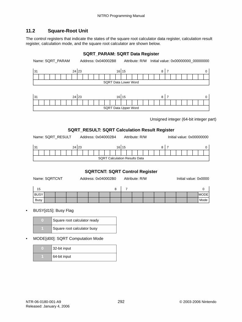
NITRO Programming Manual
11.2 Square-Root UnitThe control registers that indicate the states of the square root calculator data register, calculation result register, calculation mode, and the square root calculator are shown below.
SQRT_PARAM: SQRT Data RegisterName: SQRT_PARAM Address: 0x040002B8 Attribute: R/W Initial value: 0x00000000_00000000
Unsigned integer (64-bit integer part)
SQRT_RESULT: SQRT Calculation Result RegisterName: SQRT_RESULT Address: 0x040002B4 Attribute: R/W Initial value: 0x00000000
SQRTCNT: SQRT Control RegisterName: SQRTCNT Address: 0x040002B0 Attribute: R/W Initial value: 0x0000
• BUSY[d15]: Busy Flag
• MODE[d00]: SQRT Computation Mode
0 Square root calculator ready
1 Square root calculator busy
0 32-bit input
1 64-bit input
SQRT Data Lower Word
31 24 23 16 15 8 7 0
SQRT Data Upper Word
31 24 23 16 15 8 7 0
SQRT Calculation Results Data
31 24 23 16 15 8 7 0
BUSY MODE
Busy Mode
15 8 7 0
NTR-06-0180-001-A9 292 © 2003-2006 NintendoReleased: January 4, 2006
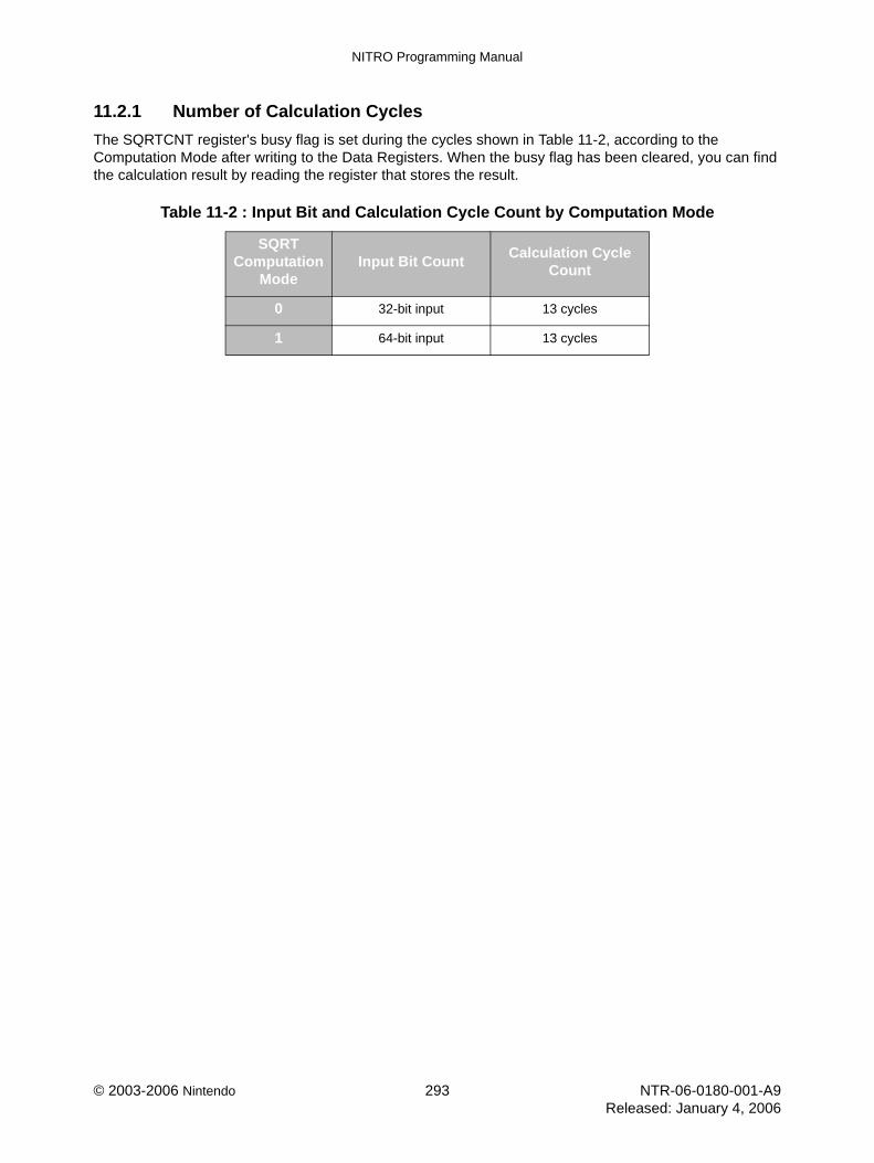
NITRO Programming Manual
11.2.1 Number of Calculation CyclesThe SQRTCNT register's busy flag is set during the cycles shown in Table 11-2, according to the Computation Mode after writing to the Data Registers. When the busy flag has been cleared, you can find the calculation result by reading the register that stores the result.
Table 11-2 : Input Bit and Calculation Cycle Count by Computation Mode
SQRT Computation
ModeInput Bit Count Calculation Cycle
Count
0 32-bit input 13 cycles
1 64-bit input 13 cycles
© 2003-2006 Nintendo 293 NTR-06-0180-001-A9Released: January 4, 2006
NITRO Programming Manual
NTR-06-0180-001-A9 294 © 2003-2006 NintendoReleased: January 4, 2006
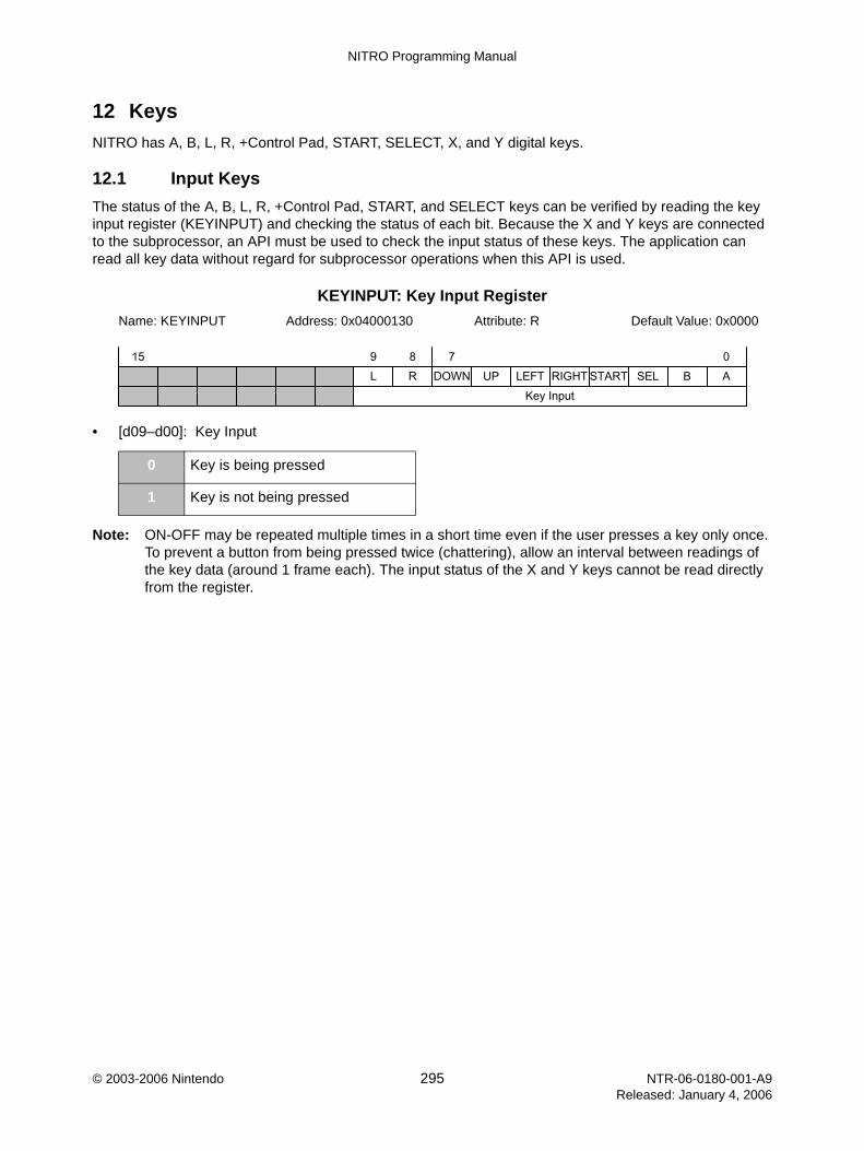
NITRO Programming Manual
12 KeysNITRO has A, B, L, R, +Control Pad, START, SELECT, X, and Y digital keys.
12.1 Input KeysThe status of the A, B, L, R, +Control Pad, START, and SELECT keys can be verified by reading the key input register (KEYINPUT) and checking the status of each bit. Because the X and Y keys are connected to the subprocessor, an API must be used to check the input status of these keys. The application can read all key data without regard for subprocessor operations when this API is used.
KEYINPUT: Key Input RegisterName: KEYINPUT Address: 0x04000130 Attribute: R Default Value: 0x0000
• [d09–d00]: Key Input
Note: ON-OFF may be repeated multiple times in a short time even if the user presses a key only once. To prevent a button from being pressed twice (chattering), allow an interval between readings of the key data (around 1 frame each). The input status of the X and Y keys cannot be read directly from the register.
0 Key is being pressed
1 Key is not being pressed
L R DOWN UP LEFT RIGHT START SEL B AKey Input
15 9 8 7 0
© 2003-2006 Nintendo 295 NTR-06-0180-001-A9Released: January 4, 2006

NITRO Programming Manual
12.2 Interrupt Handling for Key InputKey input from the A, B, L, R, +Control Pad, START, and SELECT keys can generate interrupts. The key control register (KEYCNT) can be used to specify the key combinations and conditions for which interrupts can be generated.
KEYCNT: Key Control RegisterName: KEYCNT Address: 0x04000132 Attribute: R/W Default Value: 0x0000
• LOGIC[d15] : Logic Specification Flag
• INTR[d14] : Interrupt Request Enable Flag
• [d09–d00] : Key Selection
Note: Interrupt handling cannot be specified for X or Y key input.
0 Detects if any of the specified keys was pressed
1 Detects if all of the specified keys were pressed
0 Disable
1 Enable
0 Key is not specified
1 Key is specified
LOGIC INTR L R DOWN UP LEFT RIGHT START SEL B ALogic Interrupt Key Selection
15 9 8 7 0
Interrupt Request Enable Flag
Logic Specification Flag
NTR-06-0180-001-A9 296 © 2003-2006 NintendoReleased: January 4, 2006

NITRO Programming Manual
13 SoundNITRO contains a sound circuit that enables the processing of 16-channels of simultaneous sound generation, two sound capture devices that can write the output from a specific channel or a mixer to memory, left and right speakers that can output sound, and a headphone output jack.
Since the subprocessor carries out the sequence processing and the sound generation processing, there will be no heavy burden on the main processor even when sound processing is performed.
The sound circuit is illustrated in Figure 13-1.
Figure 13-1 : The Sound Circuit Outline Diagram
Left
Amp
Left Speaker
Right Speaker
Headphone Jack
Left
Mix
er
Channel 0
Channel 1
Channel 14
Channel 15
Waveform Data
Waveform Data
Waveform Data
Waveform Data
Rig
ht A
mp
Rig
ht M
ixer
Maximum of 16 channels can be used concurrently
© 2003-2006 Nintendo 297 NTR-06-0180-001-A9Released: January 4, 2006
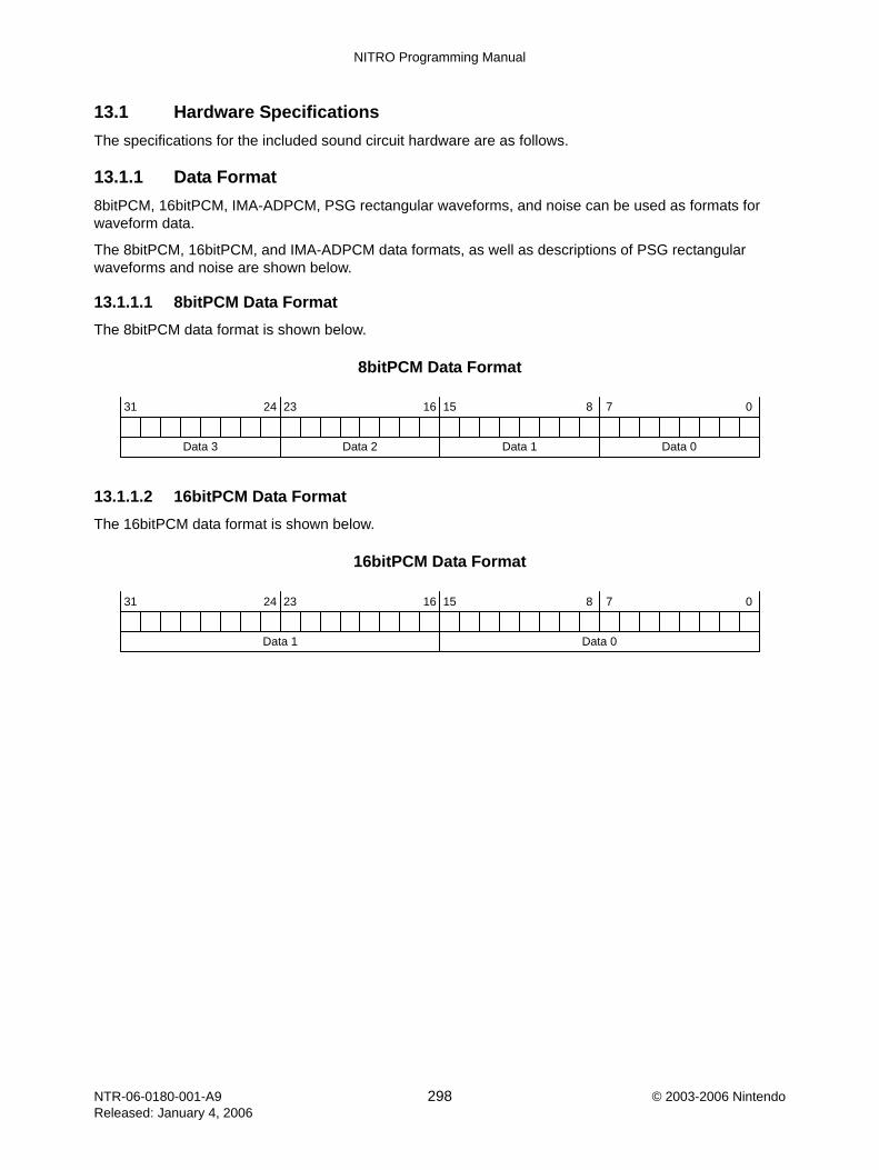
NITRO Programming Manual
13.1 Hardware SpecificationsThe specifications for the included sound circuit hardware are as follows.
13.1.1 Data Format8bitPCM, 16bitPCM, IMA-ADPCM, PSG rectangular waveforms, and noise can be used as formats for waveform data.
The 8bitPCM, 16bitPCM, and IMA-ADPCM data formats, as well as descriptions of PSG rectangular waveforms and noise are shown below.
13.1.1.1 8bitPCM Data FormatThe 8bitPCM data format is shown below.
8bitPCM Data Format
13.1.1.2 16bitPCM Data FormatThe 16bitPCM data format is shown below.
16bitPCM Data Format
Data 3 Data 2 Data 1 Data 0
31 24 23 16 15 8 7 0
Data 1 Data 0
31 24 23 16 15 8 7 0
NTR-06-0180-001-A9 298 © 2003-2006 NintendoReleased: January 4, 2006

NITRO Programming Manual
13.1.1.3 IMA-ADPCM Data FormatThe header and data parts of the IMA-ADPCM data format are shown below.
IMA-ADPCM Header Format (First 32 bits)
IMA-ADPCM Data Format (From the 33rd bit)
Note: When repeatedly playing the ADPCM with the repeat feature, set the repeat pointer to the address of the data section rather than that of the header section.
Also, if the repeat pointer is altered after starting playback on ADPCM, normal repeat play is not possible.
Be sure to stop playback before making changes to the repeat pointer.
13.1.1.4 PSG Rectangular WaveformsThe Programmable Sound Generator (PSG) creates tones by altering the frequency of the output rectangular waveform (square waves) and the duty ratio.
The duty ratios of the PSG rectangular waveforms used on NITRO can be altered as shown in Table 13-1.
Table 13-1 : Duty Ratio and PSG Rectangular Wave Waveforms
13.1.1.5 NoiseNoise has no configurable items.
Noise can be used to generate white noise on a channel designated for noise.
Table Index Initial Value Initial Value
31 24 23 22 16 15 8 7 0
Data 7 Data 6 Data 5 Data 4 Data 3 Data 2 Data 1 Data 0
31 24 23 16 15 8 7 0
Duty Ratio Waveform
12.5%
25.0%
62.5%
75.0%
37.5%
50.0%
87.5%
© 2003-2006 Nintendo 299 NTR-06-0180-001-A9Released: January 4, 2006

NITRO Programming Manual
13.1.2 ChannelsWaveform data can be played simultaneously from sixteen channels.
However, PSG rectangular waveforms can be played on only six specific channels and noise can be played on only two specific channels of the sixteen channels.
The volume, pitch, and pan (orientation) can be configured for each channel.
The playable channels for each format are shown in Table 13-2.
Table 13-2 : An Overview of Data Formats and Playable Channels
13.1.3 MixerNITRO comes equipped with both left and right mixers.
The sampling frequency of the mixer is 1.04876 MHz with an amplitude resolution of 24 bits, but the sampling frequency after mixing with PWM modulation is 32.768 kHz with an amplitude resolution of 10 bits.
PWM is an abbreviation of Pulse Width Modulation. As "Figure 13-2 : Pulse Width Modulation (PWM)" on page 301 shows, PWM converts the amplitude of a fixed-interval pulse to a duty ratio and then outputs it.
The stronger the amplitude, the higher the duty ratio it is converted to.
Data Format Playable Channels
8bitPCM
Can be played on all channels from 0 to 15.16bitPCM
ADPCM
PSG Rectangular Waveform
Can be played on Channels 8 to 13.8bitPCM, 16bitPCM, and ADPCM cannot be played simultaneously on a channel that is playing a PSG rectangular waveform.
NoiseCan be played on Channels 14 to 15.8bitPCM, 16bitPCM, and ADPCM cannot be played simultaneously on a channel that is playing noise.
NTR-06-0180-001-A9 300 © 2003-2006 NintendoReleased: January 4, 2006
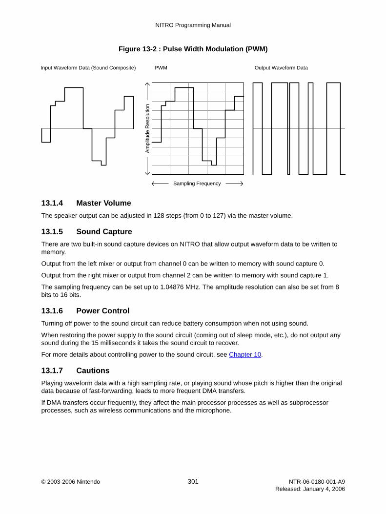
NITRO Programming Manual
Figure 13-2 : Pulse Width Modulation (PWM)
13.1.4 Master VolumeThe speaker output can be adjusted in 128 steps (from 0 to 127) via the master volume.
13.1.5 Sound CaptureThere are two built-in sound capture devices on NITRO that allow output waveform data to be written to memory.
Output from the left mixer or output from channel 0 can be written to memory with sound capture 0.
Output from the right mixer or output from channel 2 can be written to memory with sound capture 1.
The sampling frequency can be set up to 1.04876 MHz. The amplitude resolution can also be set from 8 bits to 16 bits.
13.1.6 Power ControlTurning off power to the sound circuit can reduce battery consumption when not using sound.
When restoring the power supply to the sound circuit (coming out of sleep mode, etc.), do not output any sound during the 15 milliseconds it takes the sound circuit to recover.
For more details about controlling power to the sound circuit, see Chapter 10.
13.1.7 CautionsPlaying waveform data with a high sampling rate, or playing sound whose pitch is higher than the original data because of fast-forwarding, leads to more frequent DMA transfers.
If DMA transfers occur frequently, they affect the main processor processes as well as subprocessor processes, such as wireless communications and the microphone.
Ampl
itude
Res
olut
ion
Sampling Frequency
PWMInput Waveform Data (Sound Composite) Output Waveform Data
© 2003-2006 Nintendo 301 NTR-06-0180-001-A9Released: January 4, 2006

NITRO Programming Manual
13.2 Sound Block DiagramsThis section shows the block diagrams for the NITRO sound circuits.
13.2.1 Overall SoundThe block diagram for the overall sound circuit is shown in Figure 13-3.
Figure 13-3 : The Overall Sound Block Diagram
Channel 8 (ADPCM/PCM/PSG Square Wave)
Channel 9 (ADPCM/PCM/PSG Square Wave)
Channel 10 (ADPCM/PCM/PSG Square Wave)
Channel 11 (ADPCM/PCM/PSG Square Wave)
Channel 12 (ADPCM/PCM/PSG Square Wave)
Channel 13 (ADPCM/PCM/PSG Square Wave)
Channel 14 (ADPCM/PCM/Noise)
Channel 15 (ADPCM/PCM/Noise)
Channel 0 (ADPCM/PCM)
Channel 1 (ADPCM/PCM)
Channel 2 (ADPCM/PCM)
Channel 3 (ADPCM/PCM)
Channel 4 (ADPCM/PCM)
Channel 5 (ADPCM/PCM)
Channel 6 (ADPCM/PCM)
Channel 7 (ADPCM/PCM) Mix
er
Mas
ter V
olum
e
Subprocessor(ARM7)
Work RAM64 KB
AR
M7
Bus
Sound Capture 0
Sound Capture 1
SoundDMA
FIFO
FIFO
FIFO
FIFO
FIFO
FIFO
FIFO
FIFO
FIFO
FIFO
FIFO
FIFO
FIFO
FIFO
FIFO
FIFO
ARM9 Shared Work RAM16 KB×2
Exte
rnal
Mem
ory
Inte
rface
Main Memory
4 MB
Logic
Memory
NITROGame Card
PWM
NTR-06-0180-001-A9 302 © 2003-2006 NintendoReleased: January 4, 2006

NITRO Programming Manual
13.2.2 Channels 0 – 3 and Sound Capture 0 - 1The block diagram for channels 0 to 3 and sound capture 0 and 1 is shown in Figure 13-4.
Figure 13-4 : The Channel 0-3 and Sound Capture 0-1 Block Diagram
ADPCMPCM
Timer
FIFO Pan0
Capture
Timer
FIFO
ADPCMPCMFIFO
Channel 0
Sound Capture 0
Pan1
ADPCMPCM
Timer
FIFO Pan2
Capture
Timer
FIFO
ADPCMPCMFIFO
Channel 2
Sound Capture 1
Pan3
Channel 1
Channel 3
SoundDMA
Subprocessor Bus
PWM
L
PWM
R
S 3 _RS 1 _R
S 2 _P
S 3 _Q
S 1 _R
S 2 _P
S 3 _R
S 3 _Q
Add
Add
Add
Add
Pan0
Pan2
Volu
me
Volu
me
Vol
ume
Volu
me
Sel
ecto
r 1Se
lect
or 0
Mix
erM
ixer
Sele
ctor
A
Mas
ter V
olum
e
Sel
ecto
r B
Mas
ter V
olum
e
© 2003-2006 Nintendo 303 NTR-06-0180-001-A9Released: January 4, 2006

NITRO Programming Manual
Caution 1: The switches before and after the pan blocks of channels 1 and 3 are always circuits connected to selectors A and B of the final-step output selection. Therefore, when channels 1 or 3 are selected as final-step outputs, sound will be output. Be aware of this when you do not want to output any sound.
Caution 2: The input signal to the mixer from the pan blocks of channels 1 and 3 is determined by the pri-ority shown on Table 13-3. When channels 1 and 3 are set to bypass to the final-step output, the added channels are input to the mixer. Even if the output of that mixer is configured to be captured, channels 1 and 3 will not be input to the mixer (the switch immediately after the pan block will connect to GND, and the mixer input will always be 0 in this case only). As a result, there will be no reverb. Be aware that reverb using both the mixer and adder is not possible when channels 1 and 3 are set to bypass to the final-step output. If you are considering Cau-tion 3 below, it is recommended that you use only the mixer.
Table 13-3 : Switch Input Priority from Channels 1 and 3 to the Mixer
Caution 3: There is a fault in the logic (preliminary to selector 0 and 1) for capturing the channel adder output. The following situations can occur:
• When adding channels 0 and 1 along with channels 2 and 3, if an overflow occurs in either of the addition results, sign-inverted data will be output.
• When adding channels 0 and 1 along with channels 2 and 3, if the signs of channels 0 and 1 and channels 2 and 3 are each negative, the capture data will be forcibly converted to the maximum negative value.
Noise will be output in the sounds from these results. To deal with these faults, make sure that the addition data does not become saturated when using the adder, and that the values for the channels 0-1 and channels 2-3 do not both become negative when not using the adder.
Priority Mixer Input Switch State
High 0 Input (Connected to GND) Sound Final-Step Output Bypass Configuration
Pan 0 along with Pan 2 Channel Addition and Capture Configuration
Low Pan 1 along with Pan 3 Normal Configuration
NTR-06-0180-001-A9 304 © 2003-2006 NintendoReleased: January 4, 2006
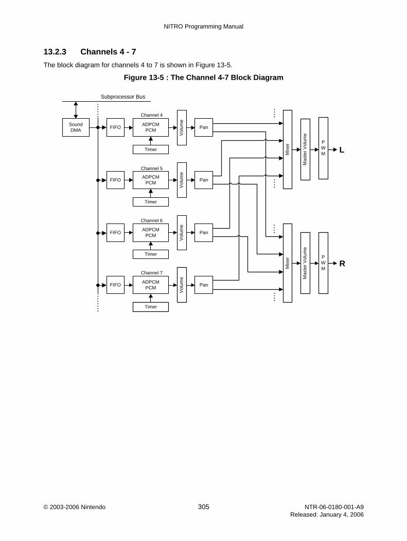
NITRO Programming Manual
13.2.3 Channels 4 - 7The block diagram for channels 4 to 7 is shown in Figure 13-5.
Figure 13-5 : The Channel 4-7 Block Diagram
ADPCMPCM
Timer
Vol
ume
FIFO Pan
Channel 4
Mix
er L
ADPCMPCM
Timer
Vol
ume
FIFO Pan
ADPCMPCM
Timer
Volu
me
FIFO Pan
ADPCMPCM
Timer
Volu
me
FIFO PanM
ixer R
SoundDMA
Subprocessor Bus
Channel 5
Channel 6
Channel 7
PWM
Mas
ter V
olum
eM
aste
r Vol
ume
PWM
© 2003-2006 Nintendo 305 NTR-06-0180-001-A9Released: January 4, 2006

NITRO Programming Manual
13.2.4 Channels 8 - 15The block diagram for channels 8 to 15 is shown in Figure 13-6. PSG rectangular waveforms can be played on channels 8 to 13. Noise can be played on channels 14 and 15.
Figure 13-6 : The Channel 8-15 Block Diagram
ADPCMPCM
Timer
Volu
me
FIFO
Pan
Channel 8
Mix
er L
Mix
er R
Sound DMA
Subprocessor Bus
Sele
ctor
PSG Square Wave Generation Circuit
ADPCMPCM
Vol
ume
FIFO
Pan
Sele
ctor
PSG Square Wave Generation Circuit
ADPCMPCM
Timer
Volu
me
FIFO
Pan
Sele
ctor
Noise Generation
Circuit
ADPCMPCM
Timer
Vol
ume
FIFO
Pan
Sel
ecto
r
Noise Generation
Circuit
Timer
Channel 13
Channel 14
Channel 15
Mas
ter V
olum
eM
aste
r Vol
ume
PWM
PWM
NTR-06-0180-001-A9 306 © 2003-2006 NintendoReleased: January 4, 2006
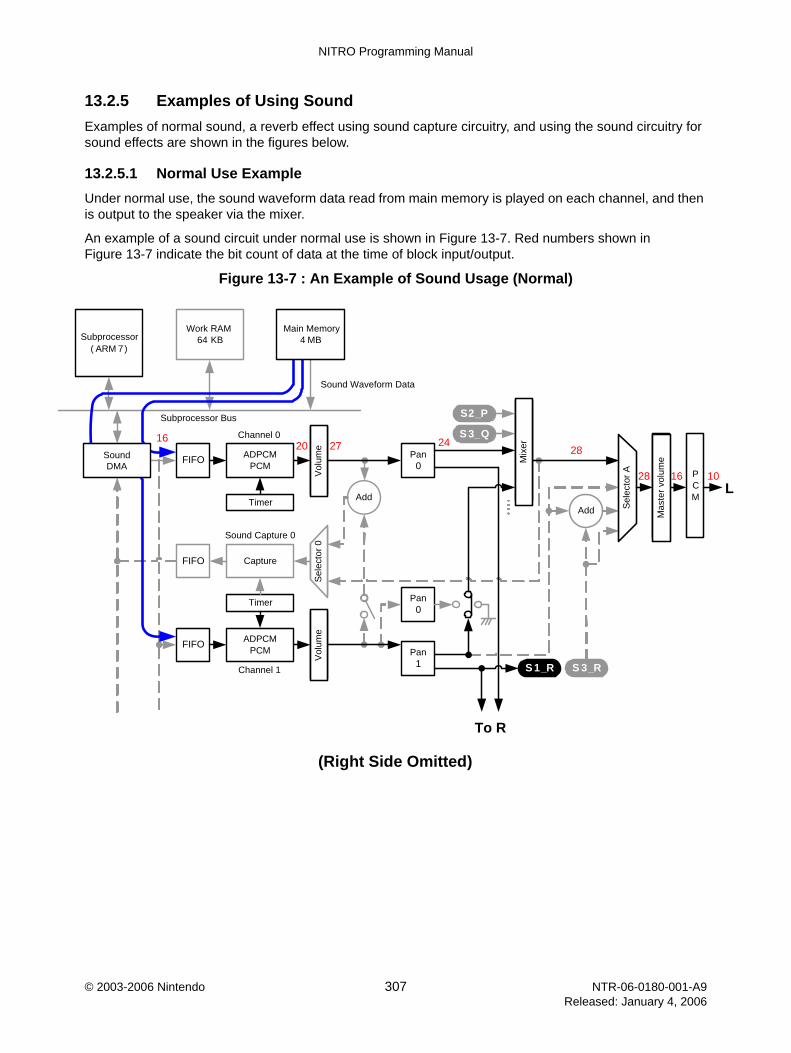
NITRO Programming Manual
L
13.2.5 Examples of Using SoundExamples of normal sound, a reverb effect using sound capture circuitry, and using the sound circuitry for sound effects are shown in the figures below.
13.2.5.1 Normal Use ExampleUnder normal use, the sound waveform data read from main memory is played on each channel, and then is output to the speaker via the mixer.
An example of a sound circuit under normal use is shown in Figure 13-7. Red numbers shown in Figure 13-7 indicate the bit count of data at the time of block input/output.
Figure 13-7 : An Example of Sound Usage (Normal)
Subprocessor Bus
FIFO ADPCMPCM
Timer
Pan0
Add
CaptureFIFO
Channel 0
FIFO ADPCMPCM
Channel 1
Timer
Sound Capture 0
Pan1
Add
S2_P
S 3_Q
S 3_RS 1_R
To R
(Right Side Omitted)
Subprocessor( ARM 7)
Work RAM64 KB
Sound Waveform Data
Sound DMA
Main Memory4 MB
PCM
1620 27 24
28
16 1028
Pan0
Volu
me
Vol
ume
Sel
ecto
r 0
Sele
ctor
A
Mas
ter v
olum
eMix
er
© 2003-2006 Nintendo 307 NTR-06-0180-001-A9Released: January 4, 2006

NITRO Programming Manual
L①
Wrti
e ca
ptur
e da
ta
13.2.5.2 Reverb ExampleA reverb effect (echo) can be achieved using the sound capture feature.
Use sound capture to store the output from the mixer in Work RAM. A reverb effect results from playing the stored sound data on a channel and outputting it to the speakers via the mixer.
An example of sound circuit usage during reverb is shown in Figure 13-8. Red numbers shown in Figure 13-8 indicate the bit count of data at the time of block input/output.
In the example, Channel 1 is used for the reverb effect.
Figure 13-8 : An Example of Sound Usage (Reverb)
Subprocessor Bus
FIFO ADPCMPCM
Timer
Pan0
Add
Capture
Channel 0
ADPCMPCM
Channel 1
Timer
Sound Capture 0
Pan1
Add
S2_P
S 3_Q
S 3_RS1_R
To RRight Side Omitted
Subprocessor( ARM 7)
Sound Waveform Data
Main Memory4 MB
FIFO
FIFO
SoundDMA
Work RAM64 KB
② Read Capture Data
Capture Data
PWM
16
24
28
2816
101628
Pan0
Vol
ume
Vol
ume
Sel
ecto
r 0
Mix
er
Sele
ctor
A
Mas
ter V
olum
e
NTR-06-0180-001-A9 308 © 2003-2006 NintendoReleased: January 4, 2006
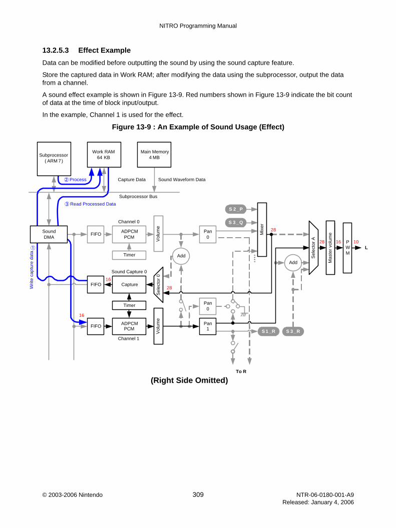
NITRO Programming Manual
L①
Writ
e ca
ptur
e da
ta
13.2.5.3 Effect ExampleData can be modified before outputting the sound by using the sound capture feature.
Store the captured data in Work RAM; after modifying the data using the subprocessor, output the data from a channel.
A sound effect example is shown in Figure 13-9. Red numbers shown in Figure 13-9 indicate the bit count of data at the time of block input/output.
In the example, Channel 1 is used for the effect.
Figure 13-9 : An Example of Sound Usage (Effect)
Subprocessor Bus
FIFO ADPCMPCM
Timer
Pan0
Add
Capture
Channel 0
ADPCMPCM
Channel 1
Timer
Sound Capture 0
Add
S 2 _P
S 3 _Q
S 3 _RS 1 _R
To R
(Right Side Omitted)
Sound Waveform Data
Main Memory4 MB
FIFO
FIFO
SoundDMA
Work RAM64 KB
③Read Processed Data
Capture Data
Subprocessor( ARM 7)
②Process
PWM
16
28
28
16
16 1028
Pan1
Pan0
Vol
ume
Vol
ume
Sel
ecto
r 0
Mix
er
Sel
ecto
r A
Mas
ter v
olum
e
© 2003-2006 Nintendo 309 NTR-06-0180-001-A9Released: January 4, 2006

NITRO Programming Manual
13.3 NITRO-ComposerThere is no need to be concerned with the subprocessor operations when using the NITRO-Composer.
The NITRO-Composer allows easy playback of even complicated sounds, such as BGM.
13.3.1 The NITRO-Composer Playback MethodThere are three playback methods: sequence playback, waveform playback, and stream playback.
13.3.1.1 Sequence PlaybackSequence playback plays a variety of combined sounds, such as BGM and sound effects.
A maximum of sixteen sequences can be played simultaneously.
For example, during playback of a BGM that has one sequence assigned to it, up to fifteen sound effects can be played simultaneously.
A variety of parameters for each sequence, such as tempo and volume, can be individually controlled on the application side.
13.3.1.2 Waveform PlaybackWaveform playback is a method for direct playback of waveform data.
It can play back waveform data, etc., that has been sampled with a microphone.
13.3.1.3 Stream PlaybackStream playback plays back long sequences, such as movie soundtracks.
Waveform data can be played back while the data stored on the NITRO card is sequentially loaded.
NTR-06-0180-001-A9 310 © 2003-2006 NintendoReleased: January 4, 2006
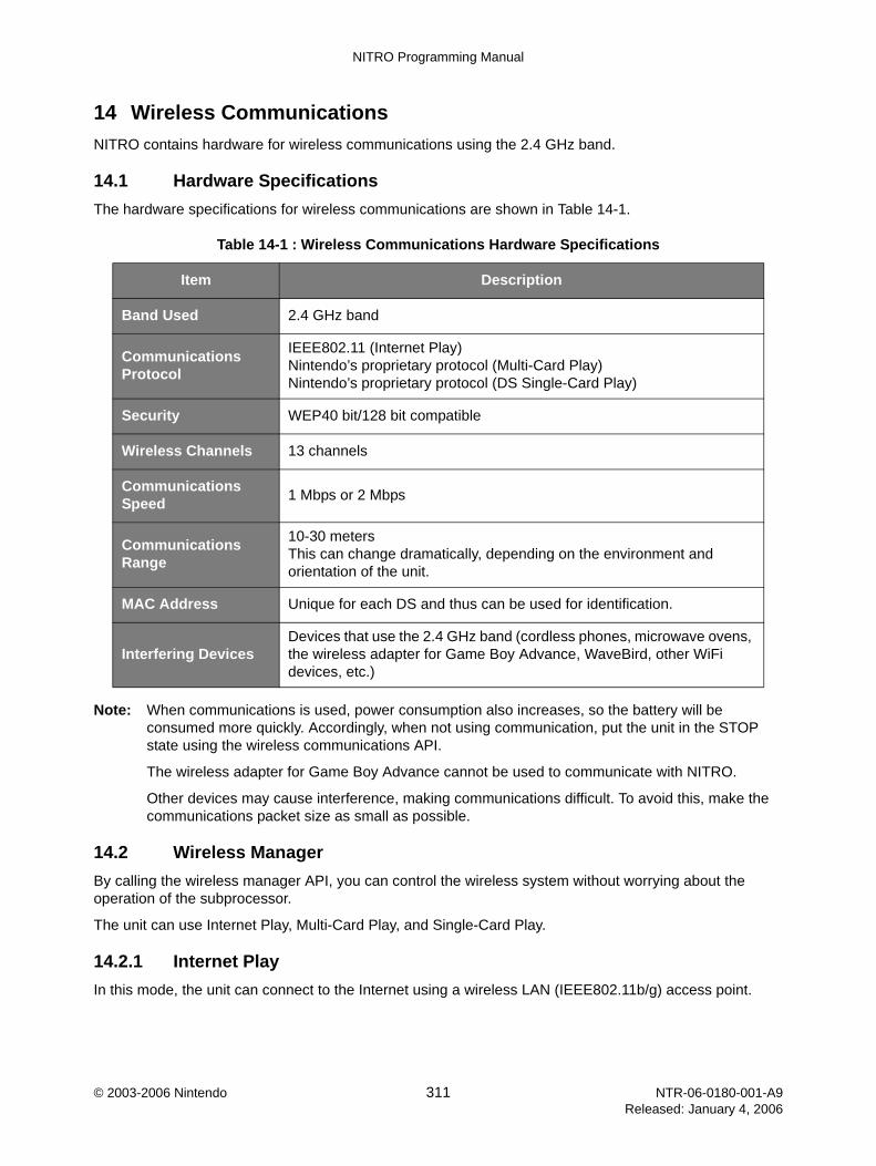
NITRO Programming Manual
14 Wireless CommunicationsNITRO contains hardware for wireless communications using the 2.4 GHz band.
14.1 Hardware SpecificationsThe hardware specifications for wireless communications are shown in Table 14-1.
Table 14-1 : Wireless Communications Hardware Specifications
Note: When communications is used, power consumption also increases, so the battery will be consumed more quickly. Accordingly, when not using communication, put the unit in the STOP state using the wireless communications API.
The wireless adapter for Game Boy Advance cannot be used to communicate with NITRO.
Other devices may cause interference, making communications difficult. To avoid this, make the communications packet size as small as possible.
14.2 Wireless ManagerBy calling the wireless manager API, you can control the wireless system without worrying about the operation of the subprocessor.
The unit can use Internet Play, Multi-Card Play, and Single-Card Play.
14.2.1 Internet PlayIn this mode, the unit can connect to the Internet using a wireless LAN (IEEE802.11b/g) access point.
Item Description
Band Used 2.4 GHz band
Communications Protocol
IEEE802.11 (Internet Play)Nintendo’s proprietary protocol (Multi-Card Play) Nintendo’s proprietary protocol (DS Single-Card Play)
Security WEP40 bit/128 bit compatible
Wireless Channels 13 channels
Communications Speed 1 Mbps or 2 Mbps
Communications Range
10-30 metersThis can change dramatically, depending on the environment and orientation of the unit.
MAC Address Unique for each DS and thus can be used for identification.
Interfering DevicesDevices that use the 2.4 GHz band (cordless phones, microwave ovens, the wireless adapter for Game Boy Advance, WaveBird, other WiFi devices, etc.)
© 2003-2006 Nintendo 311 NTR-06-0180-001-A9Released: January 4, 2006

NITRO Programming Manual
14.2.2 Multi-Card PlayThis mode allows wireless communication between a maximum of 16 DS devices.
Because it uses NITRO’s proprietary communications method, data units can be exchanged in less than one frame.
In Multi-Card Play, the maximum communications data size is 512 bytes.
14.2.3 Single-Card PlayThis mode allows a child device without a NITRO card to download a game from a parent device with a NITRO card.
If the parent device sends data with a header that includes address information, the child device’s system ROM stores the data in the region specified by the header.
This mode uses Nintendo’s proprietary protocol.
NTR-06-0180-001-A9 312 © 2003-2006 NintendoReleased: January 4, 2006
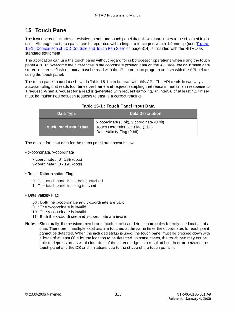
NITRO Programming Manual
15 Touch PanelThe lower screen includes a resistive-membrane touch panel that allows coordinates to be obtained in dot units. Although the touch panel can be operated with a finger, a touch pen with a 1.0 mm tip (see "Figure 15-1 : Comparison of LCD Dot Size and Touch Pen Size" on page 314) is included with the NITRO as standard equipment.
The application can use the touch panel without regard for subprocessor operations when using the touch panel API. To overcome the differences in the coordinate position data on the API side, the calibration data stored in internal flash memory must be read with the IPL correction program and set with the API before using the touch panel.
The touch panel input data shown in Table 15-1 can be read with this API. The API reads in two ways: auto-sampling that reads four times per frame and request sampling that reads in real time in response to a request. When a request for a read is generated with request sampling, an interval of at least 4.17 msec must be maintained between requests to ensure a correct reading.
Table 15-1 : Touch Panel Input Data
The details for input data for the touch panel are shown below.
• x-coordinate, y-coordinate
x-coordinate : 0 - 255 (dots)y-coordinate : 0 - 191 (dots)
• Touch Determination Flag
0 : The touch panel is not being touched1 : The touch panel is being touched
• Data Validity Flag
00 : Both the x-coordinate and y-coordinate are valid01 : The x-coordinate is invalid10 : The y-coordinate is invalid11 : Both the x-coordinate and y-coordinate are invalid
Note: Structurally, the resistive-membrane touch panel can detect coordinates for only one location at a time. Therefore, if multiple locations are touched at the same time, the coordinates for each point cannot be detected. When the included stylus is used, the touch panel must be pressed down with a force of at least 80 g for the location to be detected. In some cases, the touch pen may not be able to depress areas within four dots of the screen edge as a result of built-in error between the touch panel and the DS and limitations due to the shape of the touch pen’s tip.
Data Type Data Description
Touch Panel Input Datax coordinate (8 bit), y coordinate (8 bit)Touch Determination Flag (1 bit)Data Validity Flag (2 bit)
© 2003-2006 Nintendo 313 NTR-06-0180-001-A9Released: January 4, 2006
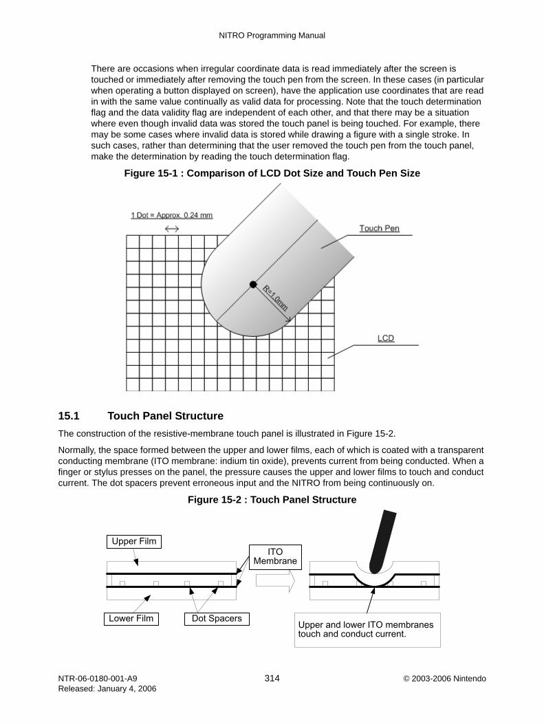
NITRO Programming Manual
There are occasions when irregular coordinate data is read immediately after the screen is touched or immediately after removing the touch pen from the screen. In these cases (in particular when operating a button displayed on screen), have the application use coordinates that are read in with the same value continually as valid data for processing. Note that the touch determination flag and the data validity flag are independent of each other, and that there may be a situation where even though invalid data was stored the touch panel is being touched. For example, there may be some cases where invalid data is stored while drawing a figure with a single stroke. In such cases, rather than determining that the user removed the touch pen from the touch panel, make the determination by reading the touch determination flag.
Figure 15-1 : Comparison of LCD Dot Size and Touch Pen Size
15.1 Touch Panel StructureThe construction of the resistive-membrane touch panel is illustrated in Figure 15-2.
Normally, the space formed between the upper and lower films, each of which is coated with a transparent conducting membrane (ITO membrane: indium tin oxide), prevents current from being conducted. When a finger or stylus presses on the panel, the pressure causes the upper and lower films to touch and conduct current. The dot spacers prevent erroneous input and the NITRO from being continuously on.
Figure 15-2 : Touch Panel Structure
ITO Membrane
Upper Film
Lower Film Dot SpacersUpper and lower ITO membranes touch and conduct current.
NTR-06-0180-001-A9 314 © 2003-2006 NintendoReleased: January 4, 2006

NITRO Programming Manual
16 MicrophoneNITRO is equipped with an omnidirectional condenser microphone that can be used for audio sampling. In addition, the user can switch to a NITRO-dedicated headset (planned for future development). In terms of sentitivity, individual variances in microphones can be as much as double depending on the console. Figure 16-1 shows a schematic of the microphone.
Figure 16-1 : Microphone Schematic
In preparation for audio sampling, the gain for audio picked up by the microphone can be adjusted to 4 levels using the programmable gain amplifier (PGA). If the audio input is low and the sampling resolution is low or if the audio input is loud, you can adjust the gain to balance the amplitude resolution. The amplitude resolution for audio sampling can be set to 8 or 12 bits.
The range of possible settings for gain and amplitude resolution are indicated in Table 16-1.
Table 16-1 : Ranges of Possible Settings for Gain and Amplitude Resolution
To use the microphone, power must be supplied to the PGA. For instructions on supplying power to the PGA, see Chapter 10.
The microphone can be used without regard for subprocessor operations when the microphone API is used. The sampling rates that can be specified range from several kHz to 32 kHz. However, the sampling rates for normal operation depend on the status of subprocessor use. The recording time depends on the memory size and sampling rate provided by the application.
The 60-Hz noise that is synched to the V-Blank is superimposed on the microphone input. However, this frequency is very low and the noise level is sufficiently low compared to audio input. Therefore, this will not cause a problem as audible sound.
Note: Wireless communication and sound processing also use the subprocessor. Therefore, if the microphone is used at the same time as these features, specify a sampling rate that takes into account the load on the subprocessor. In addition, the same serial bus is used to read touch panel data, access the internal flash memory, and control the PMIC. If the microphone is used at the same time as these features, ensure that conflicts do not occur. Do not use the microphone for 500 milliseconds after the power is turned on.
Data Type Data Description
Gain 4 levels: 20x, 40x, 80x, and 160xDefault is 40x (API specifications)
Amplitude Resolution8- or 12-bitIf 8-bit is used, one byte is used for one item of sampling dataIf 12-bit is used, two bytes are used for one item of sampling data
Serial
Internal Microphone
PGA
Power Management IC(PMIC)
AD ConverterSubprocessor
Touch Panel IC NITRO Headset
Input Switch
© 2003-2006 Nintendo 315 NTR-06-0180-001-A9Released: January 4, 2006
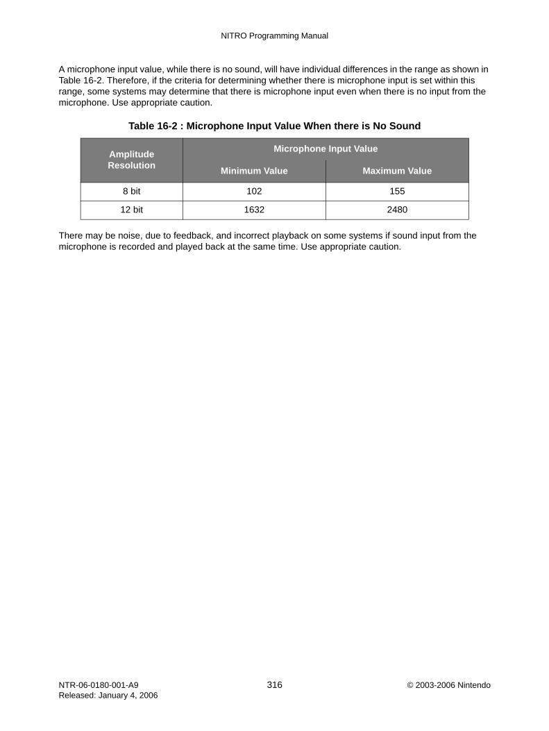
NITRO Programming Manual
A microphone input value, while there is no sound, will have individual differences in the range as shown in Table 16-2. Therefore, if the criteria for determining whether there is microphone input is set within this range, some systems may determine that there is microphone input even when there is no input from the microphone. Use appropriate caution.
Table 16-2 : Microphone Input Value When there is No Sound
There may be noise, due to feedback, and incorrect playback on some systems if sound input from the microphone is recorded and played back at the same time. Use appropriate caution.
Amplitude Resolution
Microphone Input Value
Minimum Value Maximum Value
8 bit 102 155
12 bit 1632 2480
NTR-06-0180-001-A9 316 © 2003-2006 NintendoReleased: January 4, 2006

NITRO Programming Manual
17 Real-Time Clock (RTC)The DS has an internal Real-Time Clock (RTC). Time is kept by means of an auto-calendar feature that extends through 2099 and accounts for leap years. The maximum error for the clock is ±4 seconds/day.
The time is set on the following occasions.
1. When the power is turned on for the first time after the unit is purchased.2. When the power is turned on after changing the battery.3. When the unit is restarted after the batteries have been drained (unit has been sitting for several
months with no charge in the batteries).4. When the date and time are set from the boot menu.
The RTC can be used without regard for subprocessor operations when the RTC API is used. The real-time data shown in Table 17-1 can be read with this API.
Table 17-1 : Real-Time Data
In addition, two types of alarm functions are provided. By setting the alarm from the application and engaging sleep mode, the unit can be awakened from sleep mode at a specified time. For information on sleep mode, see the section titled Power Management (cross-reference). The API can be used to read and write the following settings for Alarm 1 and Alarm 2.
Table 17-2 : Settings for Alarm 1 and Alarm 2
Note: Real-time data cannot be written from the application to the RTC.
Data Type Data Description
Real-Time Data
Year (00 - 99), month (01 - 12), date (01 - 31), day (00 - 06), hours (00 - 23), minutes (00 - 59), seconds (00 - 59)
Each value is stored as a binary coded decimal (BCD) value.
Data Type Data Description
Alarm 1 and
Alarm 2
Day (00 - 06), hour (00 - 23), minutes (00 - 59)
Separate settings for alarms 1 and 2 can be specified.Each value is stored as a binary coded decimal (BCD) value. Day, hour, and time can be enabled or disabled.
Example: The alarm can be set to activate at the same time every day by disabling the day setting.
© 2003-2006 Nintendo 317 NTR-06-0180-001-A9Released: January 4, 2006

NITRO Programming Manual
NTR-06-0180-001-A9 318 © 2003-2006 NintendoReleased: January 4, 2006

NITRO Programming Manual
18 Internal Flash MemoryThe NITRO has internal flash memory to store touch panel calibration data, owner information, the NITRO initial setting data, and RTC operation information data. The internal flash memory is dedicated memory for the storage of NITRO setting data; the application cannot write to the internal flash memory.
18.1 Touch Panel Calibration DataThis calibration data is used to compensate for the variation in coordinate positioning data between individual touch panels. If an application uses the touch panel, the touch panel must be set by reading the calibration data with the API.
18.2 Owner Information DataThe owner information data stores information about the owner of the DS. Using the API, the owner information in Table 18-1 can be read.
Table 18-1 : Owner Information Data
The details of the owner information data are shown below.
• User ID (Nickname)
Nickname string : Maximum of 10 Unicode (UTF16) characters (20 bytes). No termination code.
String length : Nickname string length (2 bytes).
• User Color (Favorite color)
0-15 : Selected from a set of 16 colors determined by IPL. (RGB values are enclosed by parentheses.)0: GRAY (12,16,19) 1: BROWN (23, 9, 0)2: RED (31, 0, 3) 3: PINK (31,17,31)4: ORANGE (31,18, 0) 5: YELLOW (30,28, 0)6: LIME GREEN (21,31, 0) 7: GREEN ( 0,31, 0)8: DARK GREEN ( 0,20, 7) 9: SEA GREEN ( 9,27,17)10: TURQUOISE ( 6,23,30) 11: BLUE ( 0,11,30)12: DARK BLUE ( 0, 0,18) 13: PURPLE (17, 0,26)14: VIOLET (26, 0,29) 15: MAGENTA (31, 0,18)
• Birthday (month and day) (Each is stored as a binary-coded decimal number.)
Month (1 byte) : Month of birth (01-12)
Day (1 byte) : Day of birth (01-31)
• Comment
A comment of two lines of a maximum of 23 characters each (23 bytes x 2 = 46 bytes) using Unicode (UTF16).
Data Type Data Contents
Owner Information Data User ID (22 bytes), User color (1 byte), Birthday (2 bytes), Comment (46 bytes)
© 2003-2006 Nintendo 319 NTR-06-0180-001-A9Released: January 4, 2006

NITRO Programming Manual
18.3 NITRO Initial Setting DataThe NITRO initial setting data stores which LCD screen is used in AGB mode and the language setting.
Using the API, the NITRO initial setting data in Table 18-2 can be read.
Table 18-2 : NITRO Initial Setting Data
The details of the NITRO initial setting data are shown below:
• LCD screen used in AGB mode
0 : Upper Screen
1 : Lower Screen
• Language setting
0 : Japanese
1 : English
2 : French
3 : German
4 : Italian
5 : Spanish
6 : Chinese
18.4 RTC Operation Information DataWhen setting the real-time clock (RTC), the difference in seconds with the initial data is set. This information can be used to determine if the user has changed the RTC data.
Using the API, the RTC operation information data in Table 18-3 can be read.
Table 18-3 : RTC Operation Information Data
Data Type Data Content
NITRO Initial Setting Data The LCD screen used in AGB mode (2 bytes) and the language setting (4 bytes)
Data Type Data Content
RTC Operation Information DataRTC offset value.This value changes each time the RTC setting is changed.
NTR-06-0180-001-A9 320 © 2003-2006 NintendoReleased: January 4, 2006

NITRO Programming Manual
Appendix A. Register List
A.1 Addresses 0x04000000 and higher
Address Offset
ARM9Register Name Page Description
0x000DISPCNT 55 2D Graphics Engine A display control
0x0020x004 DISPSTAT 51 Display status0x006 VCOUNT 53 V count comparison0x008 BG0CNT 81 2D Graphics Engine A BG0 control0x00a BG1CNT 81 2D Graphics Engine A BG1 control0x00c BG2CNT 83 2DGraphics Engine A BG2 control0x00e BG3CNT 83 2D Graphics Engine A BG3 control0x010 BG0HOFS 105 2D Graphics Engine A BG0 display H offset0x012 BG0VOFS 105 2D Graphics Engine A BG0 display V offset0x014 BG1HOFS 105 2D Graphics Engine A BG1 display H offset0x016 BG1VOFS 105 2D Graphics Engine A BG1 display V offset0x018 BG2HOFS 105 2D Graphics Engine A BG2 display H offset0x01a BG2VOFS 105 2D Graphics Engine A BG2 display V offset0x01c BG3HOFS 105 2D Graphics Engine A BG3 display H offset0x01e BG3VOFS 105 2D Graphics Engine A BG3 display V offset
0x020 BG2PA 1082D Graphics Engine A BG2 affine transformation parameters (same line X-direction reference shift dx)
0x022 BG2PB 1082D Graphics Engine A BG2 affine transformation parameters (next line X-direction reference shift dmx)
0x024 BG2PC 1082D Graphics Engine A BG2 affine transformation parameters (same line Y-direction reference shift dy)
0x026 BG2PD 1082D Graphics Engine A BG2 affine transformation parameters (next line Y-direction reference shift dmy)
0x028BG2X 107 2D Graphics Engine A BG2 reference start point
(x coordinate)0x02a0x02c
BG2Y 107 2D Graphics Engine A BG2 reference start point(y coordinate)0x02e
0x030 BG3PA 1082D Graphics Engine A BG3 affine transformation parameters (same line X-direction reference shift dx)
0x032 BG3PB 1082D Graphics Engine A BG3 affine transformation parameters (next line X-direction reference shift dmx)
© 2003-2006 Nintendo 321 NTR-06-0180-001-A9Released: January 4, 2006
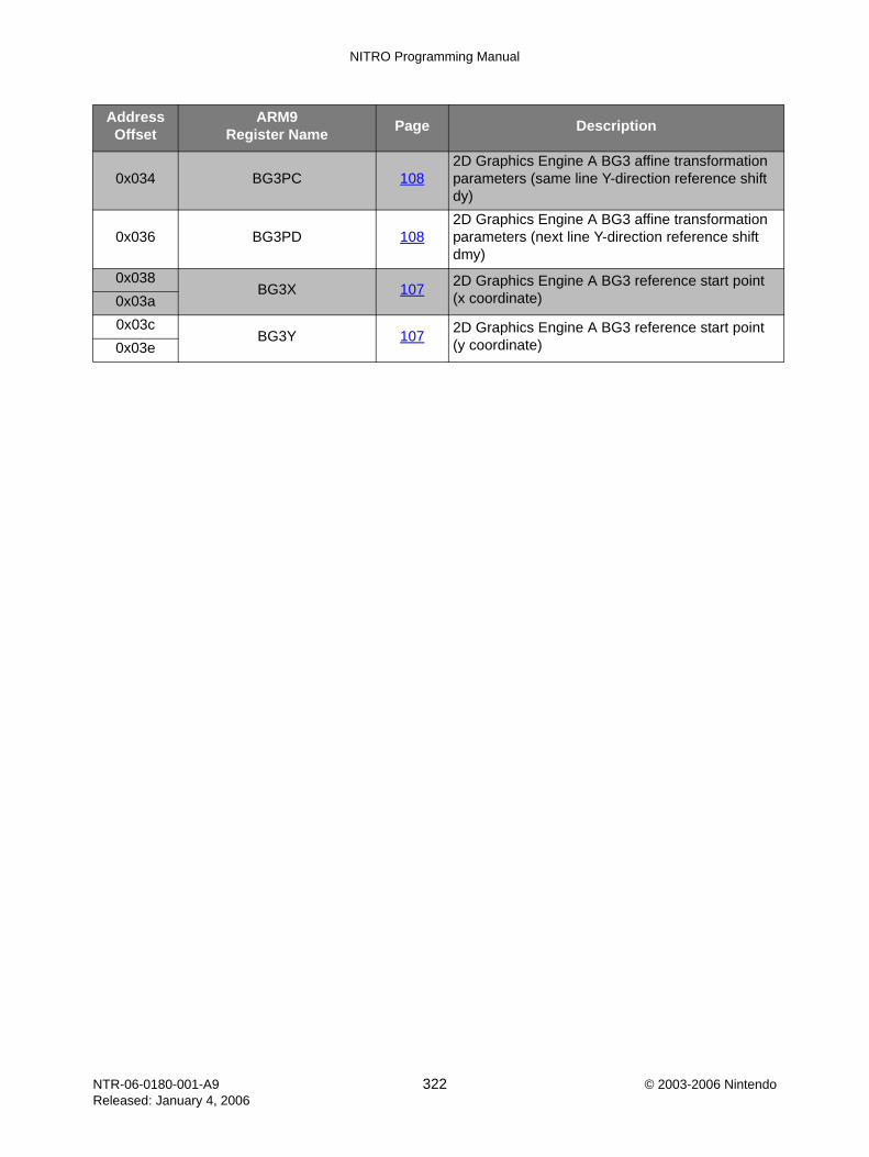
NITRO Programming Manual
0x034 BG3PC 1082D Graphics Engine A BG3 affine transformation parameters (same line Y-direction reference shift dy)
0x036 BG3PD 1082D Graphics Engine A BG3 affine transformation parameters (next line Y-direction reference shift dmy)
0x038BG3X 107 2D Graphics Engine A BG3 reference start point
(x coordinate)0x03a0x03c
BG3Y 107 2D Graphics Engine A BG3 reference start point(y coordinate)0x03e
Address Offset
ARM9Register Name Page Description
NTR-06-0180-001-A9 322 © 2003-2006 NintendoReleased: January 4, 2006

NITRO Programming Manual
Address Offset
ARM9Register Name Page Description
0x040 WIN0H 143 2D Graphics Engine A window 0 H size0x042 WIN1H 143 2D Graphics Engine A window 1 H size0x044 WIN0V 143 2D Graphics Engine A window 0 V size0x046 WIN1V 143 2D Graphics Engine A window 1 V size0x048 WININ 142 2D Graphics Engine A window inside0x04a WINOUT 142 2D Graphics Engine A window outside0x04c MOSAIC 150 2D Graphics Engine A mosaic size0x04e0x050 BLDCNT 146 2D Graphics Engine A color special effects0x052 BLDALPHA 148 2D Graphics Engine A alpha blending factor0x054 BLDY 149 2D Graphics Engine A brightness change factor0x0560x0580x05a0x05c0x05e0x060 DISP3DCNT 155 3D display control0x0620x064
DISPCAPCNT 67 Display capture0x0660x068
DISP_MMEM_FIFO 65 Main memory display FIFO0x06a0x06c MASTER_BRIGHT 71 Image output A master brightness0x06e0x0700x0720x0740x0760x0780x07a0x07c0x07e0x0800x0820x0840x0860x0880x08a
© 2003-2006 Nintendo 323 NTR-06-0180-001-A9Released: January 4, 2006

NITRO Programming Manual
0x08c0x08e0x0900x0920x0940x0960x0980x09a0x09c0x09e
Address Offset
ARM9Register Name Page Description
NTR-06-0180-001-A9 324 © 2003-2006 NintendoReleased: January 4, 2006
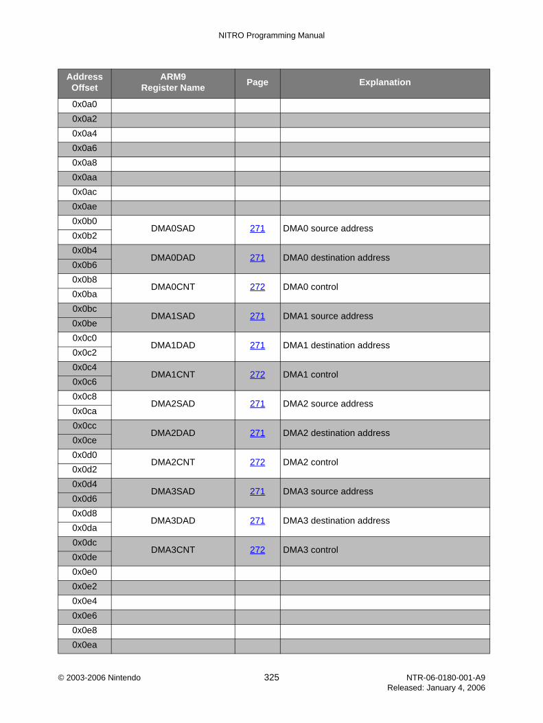
NITRO Programming Manual
Address Offset
ARM9Register Name Page Explanation
0x0a00x0a20x0a40x0a60x0a80x0aa0x0ac0x0ae0x0b0
DMA0SAD 271 DMA0 source address0x0b20x0b4
DMA0DAD 271 DMA0 destination address0x0b60x0b8
DMA0CNT 272 DMA0 control0x0ba0x0bc
DMA1SAD 271 DMA1 source address0x0be0x0c0
DMA1DAD 271 DMA1 destination address0x0c20x0c4
DMA1CNT 272 DMA1 control0x0c60x0c8
DMA2SAD 271 DMA2 source address0x0ca0x0cc
DMA2DAD 271 DMA2 destination address0x0ce0x0d0
DMA2CNT 272 DMA2 control0x0d20x0d4
DMA3SAD 271 DMA3 source address0x0d60x0d8
DMA3DAD 271 DMA3 destination address0x0da0x0dc
DMA3CNT 272 DMA3 control0x0de0x0e00x0e20x0e40x0e60x0e80x0ea
© 2003-2006 Nintendo 325 NTR-06-0180-001-A9Released: January 4, 2006
NITRO Programming Manual
0x0ec0x0ee0x0f00x0f20x0f40x0f60x0f80x0fa0x0fc0x0fe
Address Offset
ARM9Register Name Page Explanation
NTR-06-0180-001-A9 326 © 2003-2006 NintendoReleased: January 4, 2006

NITRO Programming Manual
AddressOffset
ARM9Register Name Page Explanation
0x100 TM0CNT_L 277 Timer 0 counter0x102 TM0CNT_H 277 Timer 0 control 0x104 TM1CNT_L 278 Timer 1 counter0x106 TM1CNT_H 278 Timer 1 control 0x108 TM2CNT_L 278 Timer 2 counter0x10a TM2CNT_H 278 Timer 2 control 0x10c TM3CNT_L 278 Timer 3 counter0x10e TM3CNT_H 278 Timer 3 control 0x1100x1120x1140x1160x1180x11a0x11c0x11e0x1200x1220x1240x1260x1280x12a0x12c0x12e0x130 KEYINPUT 295 Key input0x132 KEYCNT 296 Key control 0x1340x1360x1380x13a0x13c0x13e0x1400x1420x1440x1460x1480x14a
© 2003-2006 Nintendo 327 NTR-06-0180-001-A9Released: January 4, 2006
NITRO Programming Manual
0x14c0x14e0x1500x1520x1540x1560x1580x15a0x15c0x15e
AddressOffset
ARM9Register Name Page Explanation
NTR-06-0180-001-A9 328 © 2003-2006 NintendoReleased: January 4, 2006
NITRO Programming Manual
AddressOffset
ARM9 Register Name Page Explanation
0x1600x1620x1640x1660x1680x16a0x16c0x16e0x1700x1720x1740x1760x1780x17a0x17c0x17e0x1800x1820x1840x1860x1880x18a0x18c0x18e0x1900x1920x1940x1960x1980x19a0x19c0x19e0x1a00x1a20x1a40x1a60x1a80x1aa
© 2003-2006 Nintendo 329 NTR-06-0180-001-A9Released: January 4, 2006

NITRO Programming Manual
0x1ac0x1ae0x1b00x1b20x1b40x1b60x1b80x1ba0x1bc0x1be
AddressOffset
ARM9 Register Name Page Explanation
NTR-06-0180-001-A9 330 © 2003-2006 NintendoReleased: January 4, 2006

NITRO Programming Manual
AddressOffset
ARM9 Register Name Page Explanation
0x1c00x1c20x1c40x1c60x1c80x1ca0x1cc0x1ce0x1d00x1d20x1d40x1d60x1d80x1da0x1dc0x1de0x1e00x1e20x1e40x1e60x1e80x1ea0x1ec0x1ee0x1f00x1f20x1f40x1f60x1f80x1fa0x1fc0x1fe0x2000x2020x204 EXMEMCNT 11 External memory control 0x2060x208 IME 279 Interrupt master flag0x20a
© 2003-2006 Nintendo 331 NTR-06-0180-001-A9Released: January 4, 2006
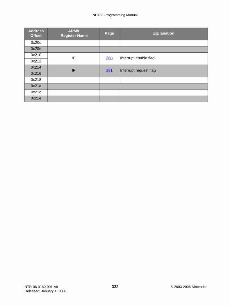
NITRO Programming Manual
0x20c0x20e0x210
IE 280 Interrupt enable flag0x2120x214
IF 281 Interrupt request flag0x2160x2180x21a0x21c0x21e
AddressOffset
ARM9 Register Name Page Explanation
NTR-06-0180-001-A9 332 © 2003-2006 NintendoReleased: January 4, 2006

NITRO Programming Manual
AddressOffset
ARM9 Register Name Page Explanation
0x2200x2220x2240x2260x2280x22a0x22c0x22e0x2300x2320x2340x2360x2380x23a0x23c0x23e0x240
VRAMCNT 19 RAM bank control 00x2420x244
WVRAMCNT 23 RAM bank control 10x2460x248 VRAM_HI_CNT 26 RAM bank control 20x24a0x24c0x24e0x2500x2520x2540x2560x2580x25a0x25c0x25e0x2600x2620x2640x2660x2680x26a
© 2003-2006 Nintendo 333 NTR-06-0180-001-A9Released: January 4, 2006
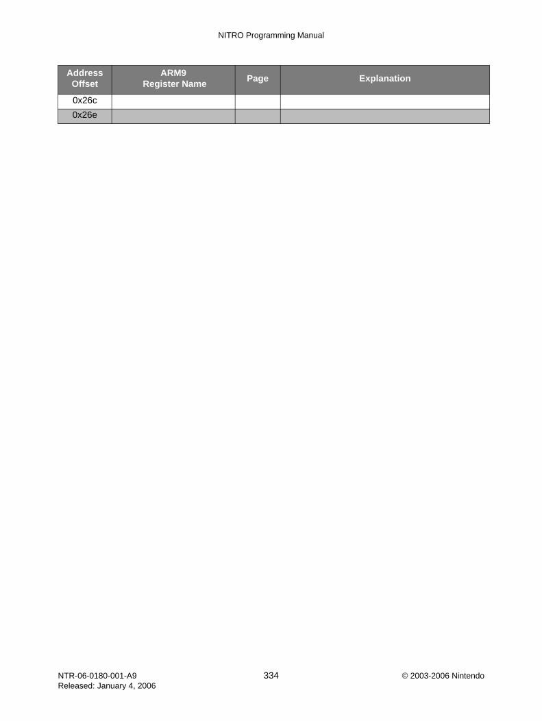
NITRO Programming Manual
0x26c0x26e
AddressOffset
ARM9 Register Name Page Explanation
NTR-06-0180-001-A9 334 © 2003-2006 NintendoReleased: January 4, 2006
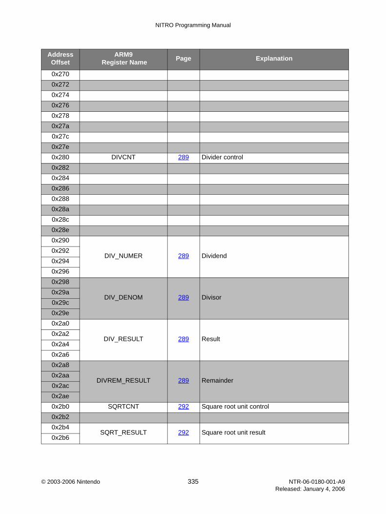
NITRO Programming Manual
AddressOffset
ARM9 Register Name Page Explanation
0x2700x2720x2740x2760x2780x27a0x27c0x27e0x280 DIVCNT 289 Divider control 0x2820x2840x2860x2880x28a0x28c0x28e0x290
DIV_NUMER 289 Dividend0x2920x2940x2960x298
DIV_DENOM 289 Divisor0x29a0x29c0x29e0x2a0
DIV_RESULT 289 Result0x2a20x2a40x2a60x2a8
DIVREM_RESULT 289 Remainder0x2aa0x2ac0x2ae0x2b0 SQRTCNT 292 Square root unit control 0x2b20x2b4
SQRT_RESULT 292 Square root unit result0x2b6
© 2003-2006 Nintendo 335 NTR-06-0180-001-A9Released: January 4, 2006

NITRO Programming Manual
0x2b8
SQRT_PARAM 292 Square root unit data0x2ba0x2bc0x2be0x2c00x2c20x2c40x2c60x2c80x2ca0x2cc0x2ce
AddressOffset
ARM9 Register Name Page Explanation
NTR-06-0180-001-A9 336 © 2003-2006 NintendoReleased: January 4, 2006
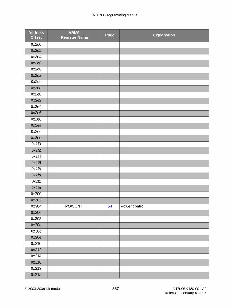
NITRO Programming Manual
AddressOffset
ARM9 Register Name Page Explanation
0x2d00x2d20x2d40x2d60x2d80x2da0x2dc0x2de0x2e00x2e20x2e40x2e60x2e80x2ea0x2ec0x2ee0x2f00x2f20x2f40x2f60x2f80x2fa0x2fc0x2fe0x3000x3020x304 POWCNT 54 Power control 0x3060x3080x30a0x30c0x30e0x3100x3120x3140x3160x3180x31a
© 2003-2006 Nintendo 337 NTR-06-0180-001-A9Released: January 4, 2006

NITRO Programming Manual
0x31c0x31e
AddressOffset
ARM9 Register Name Page Explanation
NTR-06-0180-001-A9 338 © 2003-2006 NintendoReleased: January 4, 2006
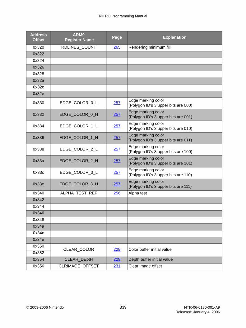
NITRO Programming Manual
AddressOffset
ARM9 Register Name Page Explanation
0x320 RDLINES_COUNT 265 Rendering minimum fill0x3220x3240x3260x3280x32a0x32c0x32e
0x330 EDGE_COLOR_0_L 257 Edge marking color(Polygon ID’s 3 upper bits are 000)
0x332 EDGE_COLOR_0_H 257 Edge marking color(Polygon ID’s 3 upper bits are 001)
0x334 EDGE_COLOR_1_L 257 Edge marking color(Polygon ID’s 3 upper bits are 010)
0x336 EDGE_COLOR_1_H 257 Edge marking color(Polygon ID’s 3 upper bits are 011)
0x338 EDGE_COLOR_2_L 257 Edge marking color(Polygon ID’s 3 upper bits are 100)
0x33a EDGE_COLOR_2_H 257 Edge marking color(Polygon ID’s 3 upper bits are 101)
0x33c EDGE_COLOR_3_L 257 Edge marking color(Polygon ID’s 3 upper bits are 110)
0x33e EDGE_COLOR_3_H 257 Edge marking color(Polygon ID’s 3 upper bits are 111)
0x340 ALPHA_TEST_REF 256 Alpha test0x3420x3440x3460x3480x34a0x34c0x34e0x350
CLEAR_COLOR 229 Color buffer initial value0x3520x354 CLEAR_DEptH 229 Depth buffer initial value0x356 CLRIMAGE_OFFSET 231 Clear image offset
© 2003-2006 Nintendo 339 NTR-06-0180-001-A9Released: January 4, 2006
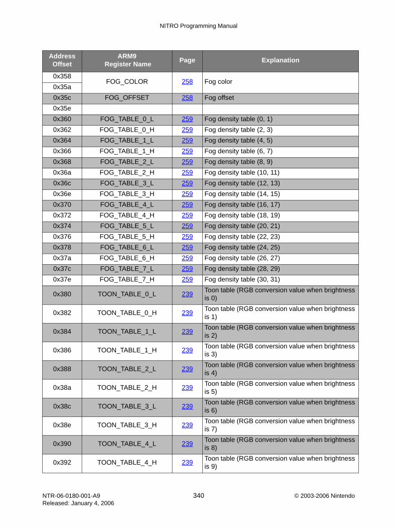
NITRO Programming Manual
AddressOffset
ARM9 Register Name Page Explanation
0x358FOG_COLOR 258 Fog color
0x35a0x35c FOG_OFFSET 258 Fog offset 0x35e0x360 FOG_TABLE_0_L 259 Fog density table (0, 1)0x362 FOG_TABLE_0_H 259 Fog density table (2, 3)0x364 FOG_TABLE_1_L 259 Fog density table (4, 5)0x366 FOG_TABLE_1_H 259 Fog density table (6, 7)0x368 FOG_TABLE_2_L 259 Fog density table (8, 9)0x36a FOG_TABLE_2_H 259 Fog density table (10, 11)0x36c FOG_TABLE_3_L 259 Fog density table (12, 13)0x36e FOG_TABLE_3_H 259 Fog density table (14, 15)0x370 FOG_TABLE_4_L 259 Fog density table (16, 17)0x372 FOG_TABLE_4_H 259 Fog density table (18, 19)0x374 FOG_TABLE_5_L 259 Fog density table (20, 21)0x376 FOG_TABLE_5_H 259 Fog density table (22, 23)0x378 FOG_TABLE_6_L 259 Fog density table (24, 25)0x37a FOG_TABLE_6_H 259 Fog density table (26, 27)0x37c FOG_TABLE_7_L 259 Fog density table (28, 29)0x37e FOG_TABLE_7_H 259 Fog density table (30, 31)
0x380 TOON_TABLE_0_L 239 Toon table (RGB conversion value when brightness is 0)
0x382 TOON_TABLE_0_H 239 Toon table (RGB conversion value when brightness is 1)
0x384 TOON_TABLE_1_L 239 Toon table (RGB conversion value when brightness is 2)
0x386 TOON_TABLE_1_H 239 Toon table (RGB conversion value when brightness is 3)
0x388 TOON_TABLE_2_L 239 Toon table (RGB conversion value when brightness is 4)
0x38a TOON_TABLE_2_H 239 Toon table (RGB conversion value when brightness is 5)
0x38c TOON_TABLE_3_L 239 Toon table (RGB conversion value when brightness is 6)
0x38e TOON_TABLE_3_H 239 Toon table (RGB conversion value when brightness is 7)
0x390 TOON_TABLE_4_L 239 Toon table (RGB conversion value when brightness is 8)
0x392 TOON_TABLE_4_H 239 Toon table (RGB conversion value when brightness is 9)
NTR-06-0180-001-A9 340 © 2003-2006 NintendoReleased: January 4, 2006
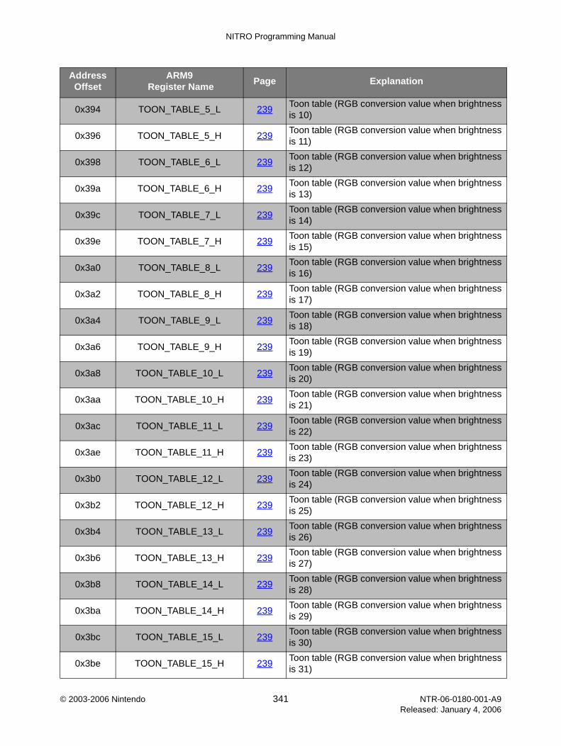
NITRO Programming Manual
0x394 TOON_TABLE_5_L 239 Toon table (RGB conversion value when brightness is 10)
0x396 TOON_TABLE_5_H 239 Toon table (RGB conversion value when brightness is 11)
0x398 TOON_TABLE_6_L 239 Toon table (RGB conversion value when brightness is 12)
0x39a TOON_TABLE_6_H 239 Toon table (RGB conversion value when brightness is 13)
0x39c TOON_TABLE_7_L 239 Toon table (RGB conversion value when brightness is 14)
0x39e TOON_TABLE_7_H 239 Toon table (RGB conversion value when brightness is 15)
0x3a0 TOON_TABLE_8_L 239 Toon table (RGB conversion value when brightness is 16)
0x3a2 TOON_TABLE_8_H 239 Toon table (RGB conversion value when brightness is 17)
0x3a4 TOON_TABLE_9_L 239 Toon table (RGB conversion value when brightness is 18)
0x3a6 TOON_TABLE_9_H 239 Toon table (RGB conversion value when brightness is 19)
0x3a8 TOON_TABLE_10_L 239 Toon table (RGB conversion value when brightness is 20)
0x3aa TOON_TABLE_10_H 239 Toon table (RGB conversion value when brightness is 21)
0x3ac TOON_TABLE_11_L 239 Toon table (RGB conversion value when brightness is 22)
0x3ae TOON_TABLE_11_H 239 Toon table (RGB conversion value when brightness is 23)
0x3b0 TOON_TABLE_12_L 239 Toon table (RGB conversion value when brightness is 24)
0x3b2 TOON_TABLE_12_H 239 Toon table (RGB conversion value when brightness is 25)
0x3b4 TOON_TABLE_13_L 239 Toon table (RGB conversion value when brightness is 26)
0x3b6 TOON_TABLE_13_H 239 Toon table (RGB conversion value when brightness is 27)
0x3b8 TOON_TABLE_14_L 239 Toon table (RGB conversion value when brightness is 28)
0x3ba TOON_TABLE_14_H 239 Toon table (RGB conversion value when brightness is 29)
0x3bc TOON_TABLE_15_L 239 Toon table (RGB conversion value when brightness is 30)
0x3be TOON_TABLE_15_H 239 Toon table (RGB conversion value when brightness is 31)
AddressOffset
ARM9 Register Name Page Explanation
© 2003-2006 Nintendo 341 NTR-06-0180-001-A9Released: January 4, 2006

NITRO Programming Manual
AddressOffset
ARM9 Register Name Page Explanation
0x3c00x3c20x3c40x3c60x3c80x3ca0x3cc0x3ce0x3d00x3d20x3d40x3d60x3d80x3da0x3dc0x3de0x3e00x3e20x3e40x3e60x3e80x3ea0x3ec0x3ee0x3f00x3f20x3f40x3f60x3f80x3fa0x3fc0x3fe
NTR-06-0180-001-A9 342 © 2003-2006 NintendoReleased: January 4, 2006
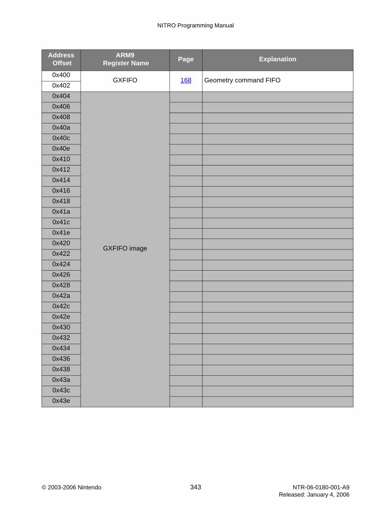
NITRO Programming Manual
Address Offset
ARM9 Register Name Page Explanation
0x400GXFIFO 168 Geometry command FIFO
0x4020x404
GXFIFO image
0x4060x4080x40a0x40c0x40e0x4100x4120x4140x4160x4180x41a0x41c0x41e0x4200x4220x4240x4260x4280x42a0x42c0x42e0x4300x4320x4340x4360x4380x43a0x43c0x43e
© 2003-2006 Nintendo 343 NTR-06-0180-001-A9Released: January 4, 2006
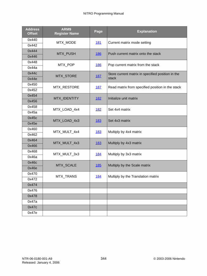
NITRO Programming Manual
AddressOffset
ARM9 Register Name Page Explanation
0x440MTX_MODE 181 Current matrix mode setting
0x4420x444
MTX_PUSH 186 Push current matrix onto the stack0x4460x448
MTX_POP 186 Pop current matrix from the stack0x44a0x44c
MTX_STORE 187 Store current matrix in specified position in the stack0x44e
0x450MTX_RESTORE 187 Read matrix from specified position in the stack
0x4520x454
MTX_IDENTITY 182 Initialize unit matrix0x4560x458
MTX_LOAD_4x4 182 Set 4x4 matrix0x45a0x45c
MTX_LOAD_4x3 183 Set 4x3 matrix0x45e0x460
MTX_MULT_4x4 183 Multiply by 4x4 matrix0x4620x464
MTX_MULT_4x3 183 Multiply by 4x3 matrix0x4660x468
MTX_MULT_3x3 184 Multiply by 3x3 matrix0x46a0x46c
MTX_SCALE 185 Multiply by the Scale matrix0x46e0x470
MTX_TRANS 184 Multiply by the Translation matrix0x4720x4740x4760x4780x47a0x47c0x47e
NTR-06-0180-001-A9 344 © 2003-2006 NintendoReleased: January 4, 2006
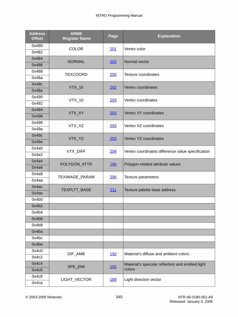
NITRO Programming Manual
Address Offset
ARM9 Register Name Page Explanation
0x480COLOR 201 Vertex color
0x4820x484
NORMAL 202 Normal vector0x4860x488
TEXCOORD 205 Texture coordinates0x48a0x48c
VTX_16 202 Vertex coordinates0x48e0x490
VTX_10 203 Vertex coordinates0x4920x494
VTX_XY 203 Vertex XY coordinates0x4960x498
VTX_XZ 203 Vertex XZ coordinates0x49a0x49c
VTX_YZ 203 Vertex YZ coordinates0x49e0x4a0
VTX_DIFF 204 Vertex coordinates difference value specification0x4a20x4a4
POLYGON_ATTR 196 Polygon-related attribute values0x4a60x4a8
TEXIMAGE_PARAM 206 Texture parameters0x4aa0x4ac
TEXPLTT_BASE 211 Texture palette base address0x4ae0x4b00x4b20x4b40x4b60x4b80x4ba0x4bc0x4be0x4c0
DIF_AMB 192 Material’s diffuse and ambient colors0x4c20x4c4
SPE_EMI 192 Material’s specular reflection and emitted light colors0x4c6
0x4c8LIGHT_VECTOR 189 Light direction vector
0x4ca
© 2003-2006 Nintendo 345 NTR-06-0180-001-A9Released: January 4, 2006

NITRO Programming Manual
0x4ccLIGHT_COLOR 189 Light color
0x4ce0x4d0
SHININESS 193 Specular reflection shininess table0x4d20x4d40x4d60x4d80x4da0x4dc0x4de
Address Offset
ARM9 Register Name Page Explanation
NTR-06-0180-001-A9 346 © 2003-2006 NintendoReleased: January 4, 2006

NITRO Programming Manual
Address Offset
ARM9 Register Name Page Explanation
0x4e00x4e20x4e40x4e60x4e80x4ea0x4ec0x4ee0x4f00x4f20x4f40x4f60x4f80x4fa0x4fc0x4fe0x500
BEGIN_VTXS 200 Vertex list start0x5020x504
END_VTXS 201 Vertex list end0x5060x5080x50a0x50c0x50e0x5100x5120x5140x5160x5180x51a0x51c0x51e0x5200x5220x5240x5260x5280x52a
© 2003-2006 Nintendo 347 NTR-06-0180-001-A9Released: January 4, 2006

NITRO Programming Manual
0x52c0x52e0x5300x5320x5340x5360x5380x53a0x53c0x53e
Address Offset
ARM9 Register Name Page Explanation
NTR-06-0180-001-A9 348 © 2003-2006 NintendoReleased: January 4, 2006

NITRO Programming Manual
Address Offset
ARM9 Register Name Page Explanation
0x540SWAP_BUFFERS 178 Swap data group
0x5420x5440x5460x5480x54a0x54c0x54e0x5500x5520x5540x5560x5580x55a0x55c0x55e0x5600x5620x5640x5660x5680x56a0x56c0x56e0x5700x5720x5740x5760x5780x57a0x57c0x57e0x580
VIEWPORT 180 Viewport0x5820x5840x5860x5880x58a
© 2003-2006 Nintendo 349 NTR-06-0180-001-A9Released: January 4, 2006

NITRO Programming Manual
0x58c0x58e0x5900x5920x5940x5960x5980x59a0x59c0x59e
Address Offset
ARM9 Register Name Page Explanation
NTR-06-0180-001-A9 350 © 2003-2006 NintendoReleased: January 4, 2006

NITRO Programming Manual
Address Offset
ARM9 Register Name Page Explanation
0x5a00x5a20x5a40x5a60x5a80x5aa0x5ac0x5ae0x5b00x5b20x5b40x5b60x5b80x5ba0x5bc0x5be0x5c0
BOX_TEST 215 Box test0x5c20x5c4
POS_TEST 216 Position coordinate test0x5c60x5c8
VEC_TEST 216 Direction vector test0x5ca0x5cc0x5ce0x5d00x5d20x5d40x5d60x5d80x5da0x5dc0x5de0x5e00x5e20x5e40x5e60x5e80x5ea
© 2003-2006 Nintendo 351 NTR-06-0180-001-A9Released: January 4, 2006

NITRO Programming Manual
0x5ec0x5ee0x5f00x5f20x5f40x5f60x5f80x5fa0x5fc0x5fe
Address Offset
ARM9 Register Name Page Explanation
NTR-06-0180-001-A9 352 © 2003-2006 NintendoReleased: January 4, 2006

NITRO Programming Manual
AddressOffset
ARM9 Register Name Page Explanation
0x600GXSTAT 218 Geometry engine status
0x6020x604 LISTRAM_COUNT 220 Polygon list RAM count0x606 VTXRAM_COUNT 220 Vertex RAM count0x6080x60a0x60c0x60e0x610 DISP_1DOT_DEptH 199 1-dot polygon display boundary depth value0x6120x6140x6160x6180x61a0x61c0x61e0x620
POS_RESULT_X 216 Result of position coordinate test (clip coordinate X component)0x622
0x624POS_RESULT_Y 216 Result of position coordinate test (clip coordinate Y
component)0x6260x628
POS_RESULT_Z 216 Result of position coordinate test (clip coordinate Z component)0x62a
0x62cPOS_RESULT_W 216 Result of position coordinate test (clip coordinate
W component)0x62e0x630 VEC_RESULT_X 217 Result of direction vector test (X component)0x632 VEC_RESULT_Y 217 Result of direction vector test (Y component)0x634 VEC_RESULT_Z 217 Result of direction vector test (Z component)0x6360x6380x63a0x63c0x63e
© 2003-2006 Nintendo 353 NTR-06-0180-001-A9Released: January 4, 2006

NITRO Programming Manual
Address Offset
ARM9 Register Name Page Explanation
0x640CLIPMTX_RESULT_0 188 Current clip coordinate matrix (element m0)
0x6420x644
CLIPMTX_RESULT_1 188 Current clip coordinate matrix (element m1)0x6460x648
CLIPMTX_RESULT_2 188 Current clip coordinate matrix (element m2)0x64a0x64c
CLIPMTX_RESULT_3 188 Current clip coordinate matrix (element m3)0x64e0x650
CLIPMTX_RESULT_4 188 Current clip coordinate matrix (element m4)0x6520x654
CLIPMTX_RESULT_5 188 Current clip coordinate matrix (element m5)0x6560x658
CLIPMTX_RESULT_6 188 Current clip coordinate matrix (element m6)0x65a0x65c
CLIPMTX_RESULT_7 188 Current clip coordinate matrix (element m7)0x65e0x660
CLIPMTX_RESULT_8 188 Current clip coordinate matrix (element m8)0x6620x664
CLIPMTX_RESULT_9 188 Current clip coordinate matrix (element m9)0x6660x668
CLIPMTX_RESULT_10 188 Current clip coordinate matrix (element m10)0x66a0x66c
CLIPMTX_RESULT_11 188 Current clip coordinate matrix (element m11)0x66e0x670
CLIPMTX_RESULT_12 188 Current clip coordinate matrix (element m12)0x6720x674
CLIPMTX_RESULT_13 188 Current clip coordinate matrix (element m13)0x6760x678
CLIPMTX_RESULT_14 188 Current clip coordinate matrix (element m14)0x67a0x67c
CLIPMTX_RESULT_15 188 Current clip coordinate matrix (element m15)0x67e
NTR-06-0180-001-A9 354 © 2003-2006 NintendoReleased: January 4, 2006
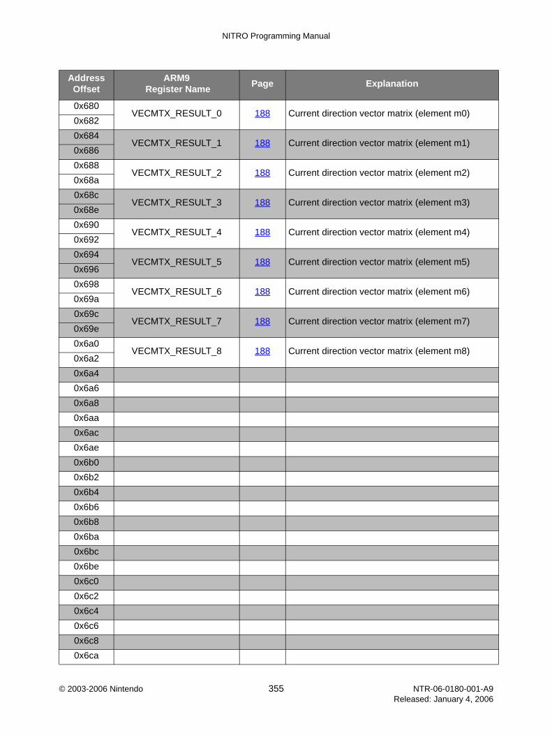
NITRO Programming Manual
AddressOffset
ARM9 Register Name Page Explanation
0x680VECMTX_RESULT_0 188 Current direction vector matrix (element m0)
0x6820x684
VECMTX_RESULT_1 188 Current direction vector matrix (element m1)0x6860x688
VECMTX_RESULT_2 188 Current direction vector matrix (element m2)0x68a0x68c
VECMTX_RESULT_3 188 Current direction vector matrix (element m3)0x68e0x690
VECMTX_RESULT_4 188 Current direction vector matrix (element m4)0x6920x694
VECMTX_RESULT_5 188 Current direction vector matrix (element m5)0x6960x698
VECMTX_RESULT_6 188 Current direction vector matrix (element m6)0x69a0x69c
VECMTX_RESULT_7 188 Current direction vector matrix (element m7)0x69e0x6a0
VECMTX_RESULT_8 188 Current direction vector matrix (element m8)0x6a20x6a40x6a60x6a80x6aa0x6ac0x6ae0x6b00x6b20x6b40x6b60x6b80x6ba0x6bc0x6be0x6c00x6c20x6c40x6c60x6c80x6ca
© 2003-2006 Nintendo 355 NTR-06-0180-001-A9Released: January 4, 2006
NITRO Programming Manual
0x6cc0x6ce0x6d00x6d20x6d40x6d60x6d80x6da0x6dc0x6de
AddressOffset
ARM9 Register Name Page Explanation
NTR-06-0180-001-A9 356 © 2003-2006 NintendoReleased: January 4, 2006
NITRO Programming Manual
Address Offset
ARM9 Register Name Page Explanation
0x6e00x6e20x6e40x6e60x6e80x6ea0x6ec0x6ee0x6f00x6f20x6f40x6f60x6f80x6fa0x6fc0x6fe
© 2003-2006 Nintendo 357 NTR-06-0180-001-A9Released: January 4, 2006

NITRO Programming Manual
A.2 Addresses 0x04001000 and higher (2D Graphics Engine B-related)
Address Offset
ARM9 Register Name Page Explanation
0x000DB_DISPCNT 57 2D Graphics Engine B display control
0x0020x0040x0060x008 DB_BG0CNT 81 2D Graphics Engine B BG0 control 0x00a DB_BG1CNT 81 2D Graphics Engine B BG1 control 0x00c DB_BG2CNT 83 2D Graphics Engine B BG2 control 0x00e DB_BG3CNT 83 2D Graphics Engine B BG3 control 0x010 DB_BG0HOFS 105 2D Graphics Engine B BG0 display H offset 0x012 DB_BG0VOFS 105 2D Graphics Engine B BG0 display V offset0x014 DB_BG1HOFS 105 2D Graphics Engine B BG1 display H offset 0x016 DB_BG1VOFS 105 2D Graphics Engine B BG1 display V offset0x018 DB_BG2HOFS 105 2D Graphics Engine B BG2 display H offset 0x01a DB_BG2VOFS 105 2D Graphics Engine B BG2 display V offset0x01c DB_BG3HOFS 105 2D Graphics Engine B BG3 display H offset 0x01e DB_BG3VOFS 105 2D Graphics Engine B BG3 display V offset
0x020 DB_BG2PA 1082D Graphics Engine B BG2 affine transformation parameters (same line X-direction reference shift dx)
0x022 DB_BG2PB 1082D Graphics Engine B BG2 affine transformation parameters (next line X-direction reference shift dmx)
0x024 DB_BG2PC 1082D Graphics Engine B BG2 affine transformation parameters (same line Y-direction reference shift dy)
0x026 DB_BG2PD 1082D Graphics Engine B BG2 affine transformation parameters (next line Y-direction reference shift dmy)
0x028DB_BG2X 107 2D Graphics Engine B BG2 reference start point
(x coordinate)0x02a0x02c
DB_BG2Y 107 2D Graphics Engine B BG2 reference start point(y coordinate)0x02e
0x030 DB_BG3PA 1082D Graphics Engine B BG3 affine transformation parameters (same line X-direction reference shift dx)
0x032 DB_BG3PB 1082D Graphics Engine B BG3 affine transformation parameters (next line X-direction reference shift dmx)
NTR-06-0180-001-A9 358 © 2003-2006 NintendoReleased: January 4, 2006
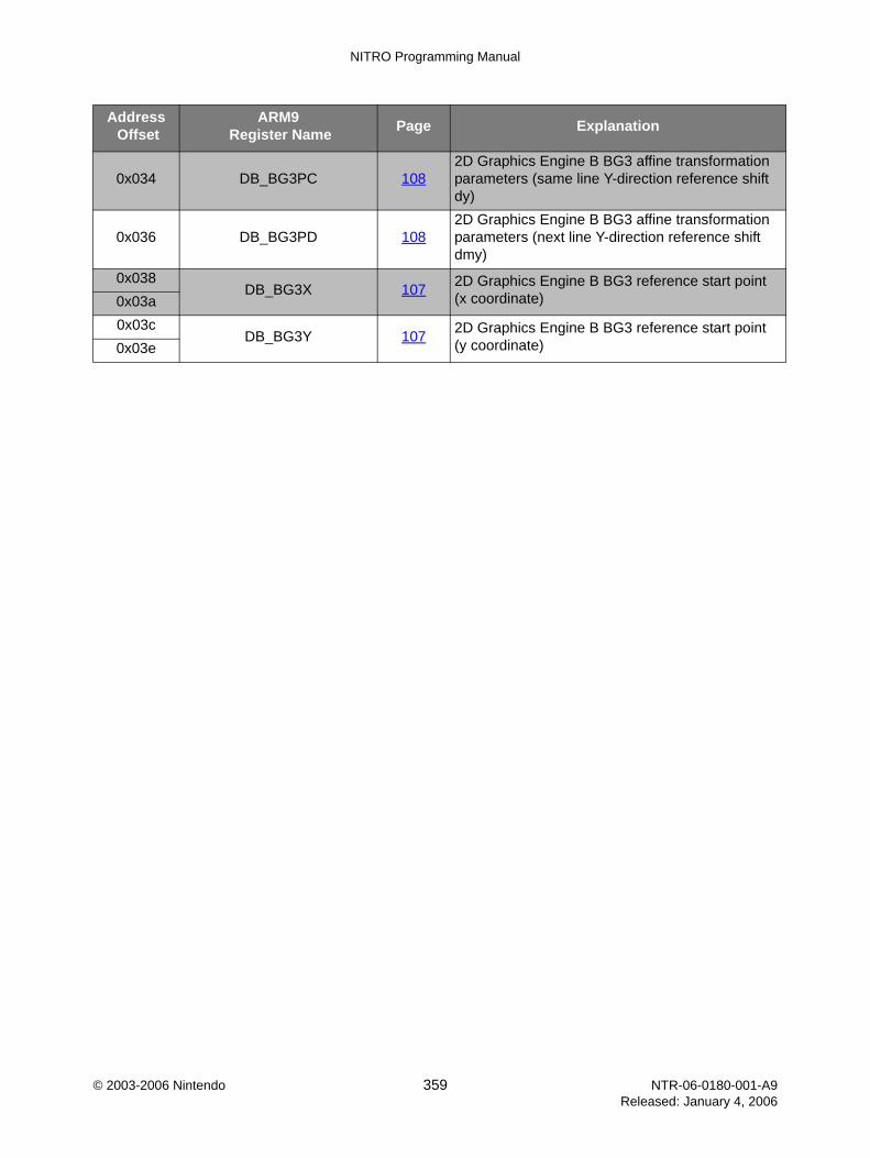
NITRO Programming Manual
0x034 DB_BG3PC 1082D Graphics Engine B BG3 affine transformation parameters (same line Y-direction reference shift dy)
0x036 DB_BG3PD 1082D Graphics Engine B BG3 affine transformation parameters (next line Y-direction reference shift dmy)
0x038DB_BG3X 107 2D Graphics Engine B BG3 reference start point
(x coordinate)0x03a0x03c
DB_BG3Y 107 2D Graphics Engine B BG3 reference start point (y coordinate)0x03e
Address Offset
ARM9 Register Name Page Explanation
© 2003-2006 Nintendo 359 NTR-06-0180-001-A9Released: January 4, 2006
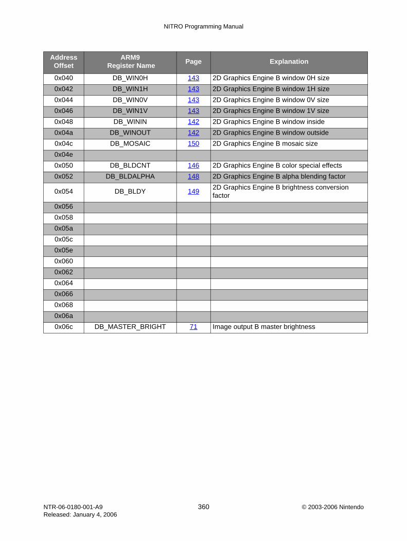
NITRO Programming Manual
AddressOffset
ARM9 Register Name Page Explanation
0x040 DB_WIN0H 143 2D Graphics Engine B window 0H size0x042 DB_WIN1H 143 2D Graphics Engine B window 1H size0x044 DB_WIN0V 143 2D Graphics Engine B window 0V size0x046 DB_WIN1V 143 2D Graphics Engine B window 1V size0x048 DB_WININ 142 2D Graphics Engine B window inside0x04a DB_WINOUT 142 2D Graphics Engine B window outside0x04c DB_MOSAIC 150 2D Graphics Engine B mosaic size0x04e0x050 DB_BLDCNT 146 2D Graphics Engine B color special effects0x052 DB_BLDALPHA 148 2D Graphics Engine B alpha blending factor
0x054 DB_BLDY 149 2D Graphics Engine B brightness conversion factor
0x0560x0580x05a0x05c0x05e0x0600x0620x0640x0660x0680x06a0x06c DB_MASTER_BRIGHT 71 Image output B master brightness
NTR-06-0180-001-A9 360 © 2003-2006 NintendoReleased: January 4, 2006
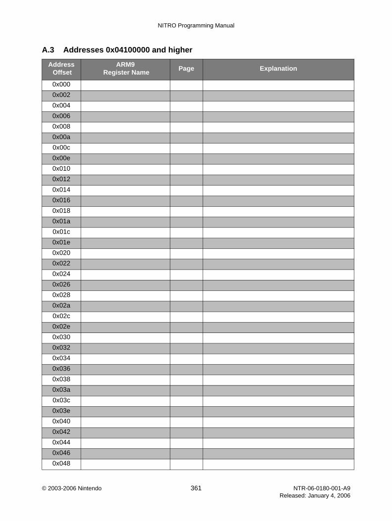
NITRO Programming Manual
A.3 Addresses 0x04100000 and higher
Address Offset
ARM9 Register Name Page Explanation
0x0000x0020x0040x0060x0080x00a0x00c0x00e0x0100x0120x0140x0160x0180x01a0x01c0x01e0x0200x0220x0240x0260x0280x02a0x02c0x02e0x0300x0320x0340x0360x0380x03a0x03c0x03e0x0400x0420x0440x0460x048
© 2003-2006 Nintendo 361 NTR-06-0180-001-A9Released: January 4, 2006
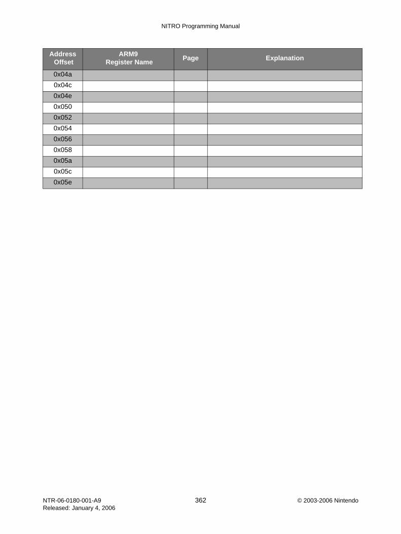
NITRO Programming Manual
0x04a0x04c0x04e0x0500x0520x0540x0560x0580x05a0x05c0x05e
Address Offset
ARM9 Register Name Page Explanation
NTR-06-0180-001-A9 362 © 2003-2006 NintendoReleased: January 4, 2006
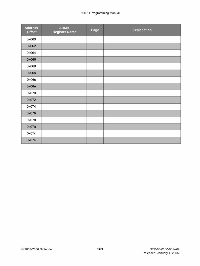
NITRO Programming Manual
Address Offset
ARM9 Register Name Page Explanation
0x060
0x062
0x064
0x066
0x068
0x06a
0x06c
0x06e
0x070
0x072
0x074
0x076
0x078
0x07a
0x07c
0x07e
© 2003-2006 Nintendo 363 NTR-06-0180-001-A9Released: January 4, 2006

NITRO Programming Manual
NTR-06-0180-001-A9 364 © 2003-2006 NintendoReleased: January 4, 2006

NITRO Programming Manual
024x024
X
X
X
X
6K
2K
X
X
X
X
X
X
6K
2K
X
X
X
X
6K
8K
6K)
Appendix B. List of VRAM Data Capacities(Data capacity unit: bytes)
X: Outside of specifications
—: Omitted
Bold: Maximum value
( ): The maximum data value exceeds the RAM capacity. Therefore the maximum usable RAM capacity is specified.
Size
Format
8x8
16x
16
32x
32
64x
64
128x
128
256x
192
256x
256
512x
256
512x
512
1024x
512
1
1
16-Color Character 32 128 512 2K X X X X X X
256-Color Character 64 256 1K 4K X X X X X X
Direct Color Bitmap OBJ 128 512 2K 8K X X X X X X
Normal Character BG Screen X X X X X X 2K 4K 8K X
Rotated Character BG Screen X X X X 256 X 1K X 4K X 1
Extended/Rotated Character BG Screen X X X X 512 X 2K X 8K X 3
256-Color Bitmap BG X X X X 16K X 64K 128K 256K X
Large Screen 256-Color Bitmap BG X X X X X X X X X 512K
Direct Color Bitmap BG X X X X 32K X 128K 256K 512K X
Clear Color Image X X X X X 96K X X X X
Clear Depth Image X X X X X 96K X X X X
Display Capture X X X X 32K 96K X X X X
4-Color Texture 16 64 256 1K 4K — 16K — 64K — 25
16-Color Texture 32 128 512 2K 8K — 32K — 128K — 51
256-Color Texture 64 256 1K 4K 16K — 64K — 256K 512K
A3I5 Translucent Texture 64 256 1K 4K 16K — 64K — 256K 512K
A5I3 Translucent Texture 64 256 1K 4K 16K — 64K — 256K 512K
Direct Color Texture 128 512 2K 8K 32K — 128K — 512K X
Compressed Texture Image 16 64 256 1K 4K — 16K — 64K — 25
Compressed Texture Index 8 32 128 512 2K — 8K — 32K — 12
Maximum No. of Compressed Texture Interpolation Palettes 16 64 256 1K 4K — 16K — 64K (96K) (9
© 2003-2006 Nintendo 365 NTR-06-0180-001-A9Released: January 4, 2006

NITRO Programming Manual
NTR-06-0180-001-A9 366 © 2003-2006 NintendoReleased: January 4, 2006
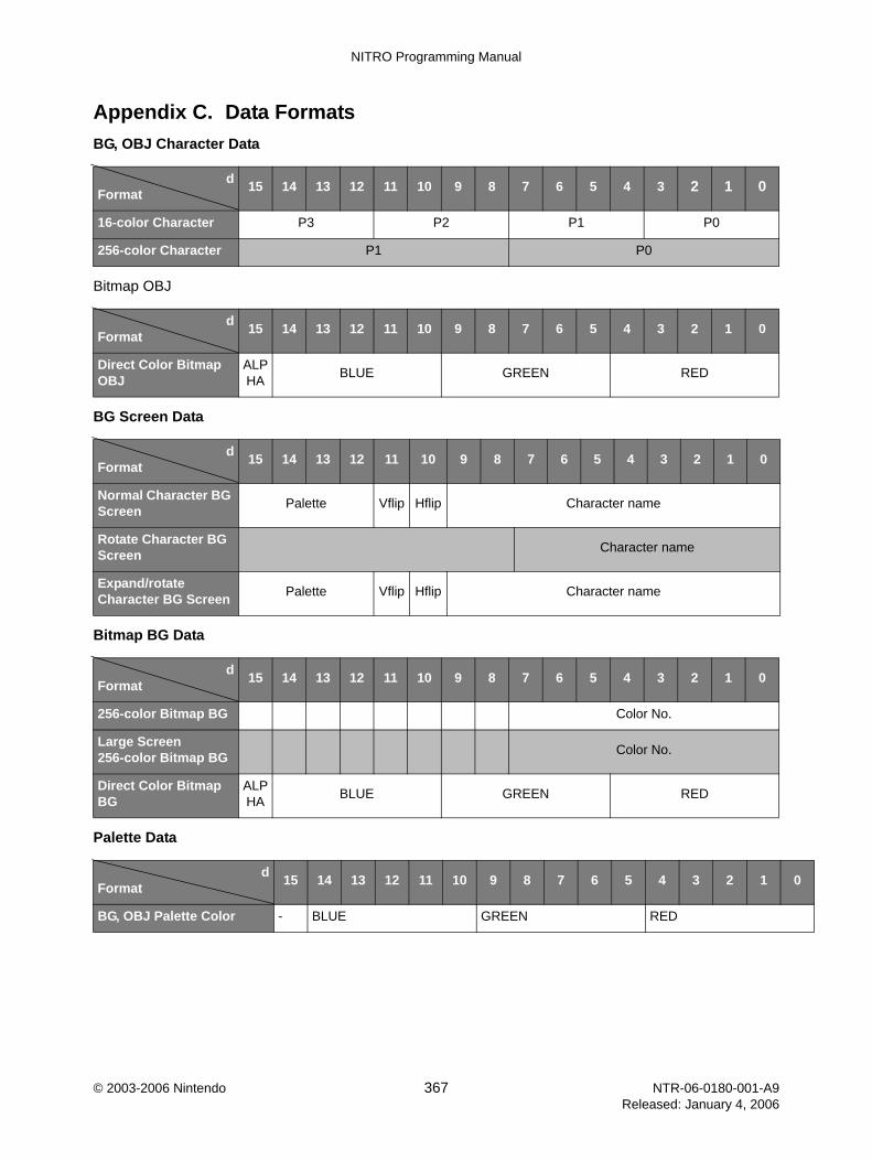
NITRO Programming Manual
0
Appendix C. Data FormatsBG, OBJ Character Data
Bitmap OBJ
BG Screen Data
Bitmap BG Data
Palette Data
dFormat 15 14 13 12 11 10 9 8 7 6 5 4 3 2 1 0
16-color Character P3 P2 P1 P0
256-color Character P1 P0
dFormat 15 14 13 12 11 10 9 8 7 6 5 4 3 2 1 0
Direct Color Bitmap OBJ
ALPHA BLUE GREEN RED
dFormat 15 14 13 12 11 10 9 8 7 6 5 4 3 2 1 0
Normal Character BG Screen Palette Vflip Hflip Character name
Rotate Character BG Screen Character name
Expand/rotate Character BG Screen Palette Vflip Hflip Character name
dFormat 15 14 13 12 11 10 9 8 7 6 5 4 3 2 1 0
256-color Bitmap BG Color No.
Large Screen 256-color Bitmap BG Color No.
Direct Color Bitmap BG
ALPHA BLUE GREEN RED
dFormat 15 14 13 12 11 10 9 8 7 6 5 4 3 2 1
BG, OBJ Palette Color - BLUE GREEN RED
© 2003-2006 Nintendo 367 NTR-06-0180-001-A9Released: January 4, 2006

NITRO Programming Manual
Other Graphics Function Data
Texture Data
Compressed Texture Data (Note: 32-bit notation)
dFormat 15 14 13 12 11 10 9 8 7 6 5 4 3 2 1 0
Clear Color Image ALPHA BLUE GREEN RED
Clear Depth Image FOGInteger portion Fractional
portion
Clear depth
Display Capture ALPHA BLUE GREEN RED
dFormat 15 14 13 12 11 10 9 8 7 6 5 4 3 2 1 0
4-color Texture T0
16-color Texture T0
256-color Texture T0
A5I3 Translucent Texture ALPHA INDEX
A3I5 Translucent Texture ALPHA INDEX
Direct Color Texture ALPHA BLUE GREEN RED
31Format
d
Compressed texture image T33
Compressed texture index
30 29 28 27 26 25 24 23 22 21 20 19 18 17 16 15 14 13 12 11 10 9 8 7 6 5 4 3 2 1 0
T32 T31 T30 T23 T22 T21 T20 T13 T12 T11 T10 T03 T02 T01 T00
3/4 T Palette Address
NTR-06-0180-001-A9 368 © 2003-2006 NintendoReleased: January 4, 2006

NITRO Programming Manual
Texture Palette Data
OAM Data
Sound Data
dFormat 15 14 13 12 11 10 9 8 7 6 5 4 3 2 1 0
Texture palette color - BLUE GREEN RED
dFormat 15 14 13 12 11 10 9 8 7 6 5 4 3 2 1 0
PCM 8 bit Data 0
PCM16 bit Data 0
ADPCM Data 0
15 14 13 12 11 10 9 8 7 6 5 4 3 2 1 0Format
d
OBJ attribute 0
OBJ attribute 1
Form
OBJ attribute 2
Affine transformation parameter PA
Affine transformation parameter PB
Affine transformation parameter PC
Decimal part
Size
Palette Number
Sign
Color mode Mosaic OBJ mode Double
size
Rotation /
Scalingy-Coordinate
V-flip H-flipAffine transformation parameter number
x-Coordinate
Order of Priority Character name
Integer part
Distance in x direction for same line
Affine transformation parameter PD
Decimal partSign Integer part
Distance in in x direction for next line
Decimal partSign Integer part
Distance in in y direction for same line
Decimal partSign Integer part
Distance in in y direction for next line
© 2003-2006 Nintendo 369 NTR-06-0180-001-A9Released: January 4, 2006

NITRO Programming Manual
NTR-06-0180-001-A9 370 © 2003-2006 NintendoReleased: January 4, 2006


![LISTADO DE JUEGOS - PinillaNumero Descripcion Foto 291 [NDS]Artic_Tale[EUR] 798 [NDS]Asphalt_Urban_GT_2[EUR] 306 [NDS]Assassins_Creed_Altairs_Chronicles[EUR] 285 [NDS]Assassins_Creed_Altairs_Chronicles[USA]](https://static.fdocuments.us/doc/165x107/5f07ebef7e708231d41f6db4/listado-de-juegos-numero-descripcion-foto-291-ndsartictaleeur-798-ndsasphalturbangt2eur.jpg)