Nd2Fe14B magnets systems –316L stainless steel to Ni/Cu/Ni ...
20
Page 1/20 Ultrasonic welding of magnetic hybrid material systems –316L stainless steel to Ni/Cu/Ni-coated Nd 2 Fe 14 B magnets Moritz Liesegang ( [email protected] ) TU Kaiserslautern: Technische Universitat Kaiserslautern https://orcid.org/0000-0003-3062-794X Tilmann Beck TU Kaiserslautern: Technische Universitat Kaiserslautern Research Keywords: Ultrasonic welding, functional hybrid material systems, rare earth permanent magnets, hybrid joints Posted Date: January 28th, 2021 DOI: https://doi.org/10.21203/rs.3.rs-88532/v2 License: This work is licensed under a Creative Commons Attribution 4.0 International License. Read Full License Version of Record: A version of this preprint was published at Functional Composite Materials on March 22nd, 2021. See the published version at https://doi.org/10.1186/s42252-021-00017-1.
Transcript of Nd2Fe14B magnets systems –316L stainless steel to Ni/Cu/Ni ...
Page 1/20
Ultrasonic welding of magnetic hybrid materialsystems –316L stainless steel to Ni/Cu/Ni-coatedNd2Fe14B magnetsMoritz Liesegang ( [email protected] )
TU Kaiserslautern: Technische Universitat Kaiserslautern https://orcid.org/0000-0003-3062-794XTilmann Beck
TU Kaiserslautern: Technische Universitat Kaiserslautern
Research
Keywords: Ultrasonic welding, functional hybrid material systems, rare earth permanent magnets, hybridjoints
Posted Date: January 28th, 2021
DOI: https://doi.org/10.21203/rs.3.rs-88532/v2
License: This work is licensed under a Creative Commons Attribution 4.0 International License. Read Full License
Version of Record: A version of this preprint was published at Functional Composite Materials on March22nd, 2021. See the published version at https://doi.org/10.1186/s42252-021-00017-1.
Page 2/20
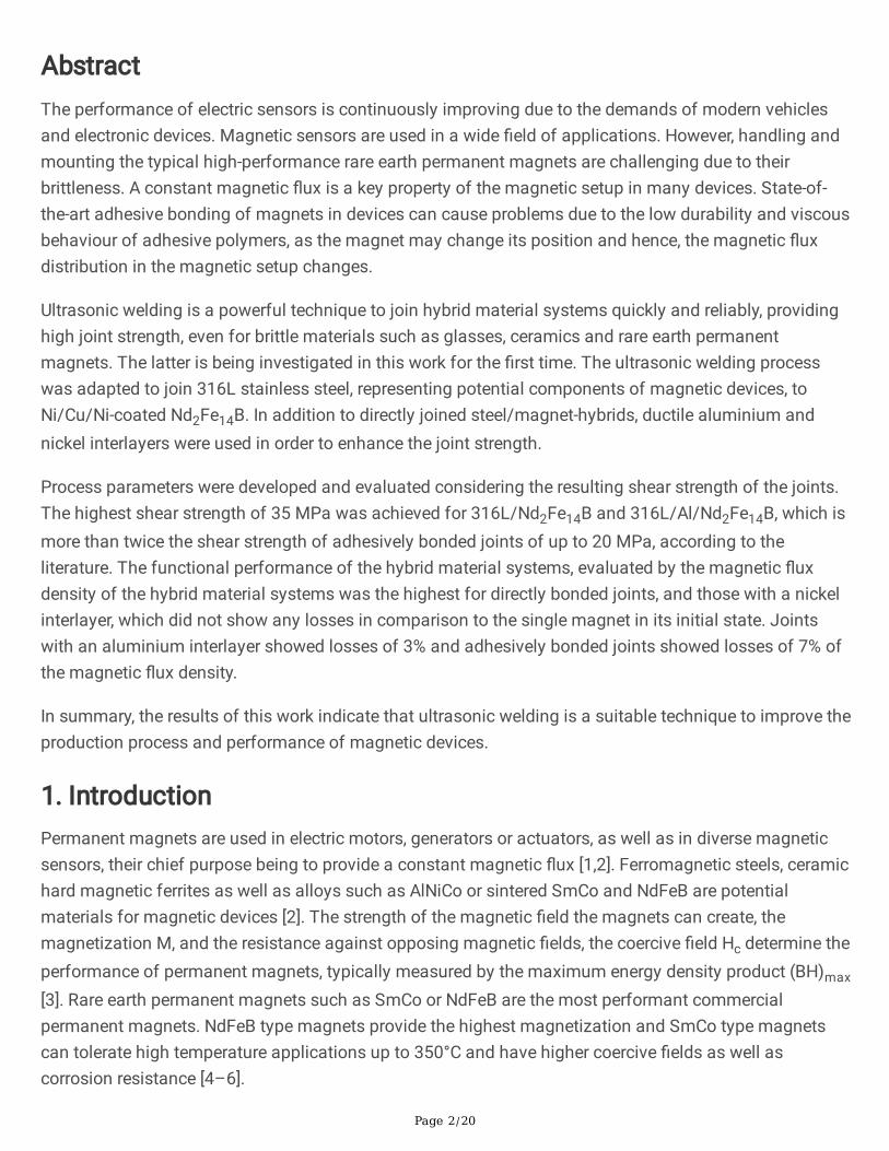
AbstractThe performance of electric sensors is continuously improving due to the demands of modern vehiclesand electronic devices. Magnetic sensors are used in a wide �eld of applications. However, handling andmounting the typical high-performance rare earth permanent magnets are challenging due to theirbrittleness. A constant magnetic �ux is a key property of the magnetic setup in many devices. State-of-the-art adhesive bonding of magnets in devices can cause problems due to the low durability and viscousbehaviour of adhesive polymers, as the magnet may change its position and hence, the magnetic �uxdistribution in the magnetic setup changes.
Ultrasonic welding is a powerful technique to join hybrid material systems quickly and reliably, providinghigh joint strength, even for brittle materials such as glasses, ceramics and rare earth permanentmagnets. The latter is being investigated in this work for the �rst time. The ultrasonic welding processwas adapted to join 316L stainless steel, representing potential components of magnetic devices, toNi/Cu/Ni-coated Nd2Fe14B. In addition to directly joined steel/magnet-hybrids, ductile aluminium andnickel interlayers were used in order to enhance the joint strength.
Process parameters were developed and evaluated considering the resulting shear strength of the joints.The highest shear strength of 35 MPa was achieved for 316L/Nd2Fe14B and 316L/Al/Nd2Fe14B, which ismore than twice the shear strength of adhesively bonded joints of up to 20 MPa, according to theliterature. The functional performance of the hybrid material systems, evaluated by the magnetic �uxdensity of the hybrid material systems was the highest for directly bonded joints, and those with a nickelinterlayer, which did not show any losses in comparison to the single magnet in its initial state. Jointswith an aluminium interlayer showed losses of 3% and adhesively bonded joints showed losses of 7% ofthe magnetic �ux density.
In summary, the results of this work indicate that ultrasonic welding is a suitable technique to improve theproduction process and performance of magnetic devices.
1. IntroductionPermanent magnets are used in electric motors, generators or actuators, as well as in diverse magneticsensors, their chief purpose being to provide a constant magnetic �ux [1,2]. Ferromagnetic steels, ceramichard magnetic ferrites as well as alloys such as AlNiCo or sintered SmCo and NdFeB are potentialmaterials for magnetic devices [2]. The strength of the magnetic �eld the magnets can create, themagnetization M, and the resistance against opposing magnetic �elds, the coercive �eld Hc determine theperformance of permanent magnets, typically measured by the maximum energy density product (BH)max
[3]. Rare earth permanent magnets such as SmCo or NdFeB are the most performant commercialpermanent magnets. NdFeB type magnets provide the highest magnetization and SmCo type magnetscan tolerate high temperature applications up to 350°C and have higher coercive �elds as well ascorrosion resistance [4–6].

Page 3/20
The time stability of the magnetic �ux is a fundamental requirement, especially for magnetic sensors, toassure reliable measurements as small changes of intrinsic magnetic properties or the position of themagnet in the measurement setup affect the accuracy of the sensors [7–9].
Due to the brittleness of rare earth permanent magnets, handling and mounting are challenging [10].Permanent magnets are typically mounted by adhesives, such as epoxy resins, and rarely by mechanicalinterlocking into diverse magnetic sensor devices [10–13]. The strength and durability of adhesive bondsare relatively low compared to other joining methods and, most importantly, the mechanical properties ofthe joints change during the lifetime of the device because of the viscosity of polymers [10,14,15].
Using adhesive joining techniques, applications at temperatures higher than 150°C are also problematicas the joint strength decreases at elevated temperatures despite the use of high-performance polymers,such as Polyphenylene sulphide (PPS) [16].
Ultrasonic welding is one promising technique to realise hybrid joints between metallic substrates andbrittle permanent magnets. So far, ultrasonic welding is mostly used in the packaging industry to reliablyjoin polymers quickly and cost-effectively [17], or to join soft non-ferrous metals such as aluminium andcopper for electrical applications [18]. Ultrasonic welding of hybrid material systems, such as metal/CFRPjoints, has been a focus of research during the last decade. For example, aluminium/CFRP joints havebeen investigated [19–22]. In addition several multi-metal combinations like aluminium and magnesium,copper, steel or titanium have been ultrasonically welded [23–28].
Ultrasonic welding of brittle materials, such as glasses and ceramics with metals is challenging and hasbeen investigated, partially using an air beared anvil and a ductile aluminium interlayer to ensurehomogeneous stress distribution on the joining partners and to prevent damage to the brittle glass andceramic parts [29,30].
According to literature the success of the ultrasonic welding process depends on process and materialparameters. Welding amplitude, force and energy, or time are important process parameters, whilemechanical properties, geometry and surface topography are material and geometrical parameters,respectively, that affect the joining quality [20].
The process parameters interact with each other and hence, always have to be assessed in combination.
The sonotrode oscillates with a certain amplitude, inducing an equivalent elastic and plastic deformationamplitude in the joining partners, that are closely pressed together by the welding force. The weldingenergy is typically de�ned as the product of the generator power and the welding time. A suitableamplitude has to be chosen in order to allow an adequate deformation without damaging the joiningpartners. A su�ciently high welding force is essential for a close contact of the joining partners in theinterface without inhibiting the oscillation or damaging the joining partners. The welding energy is thetime dependent power provided by the ultrasound generator which hence, is suitable control parameterfor the ultrasonic welding machine. In comparison to simply control the process by welding time, the
Page 4/20
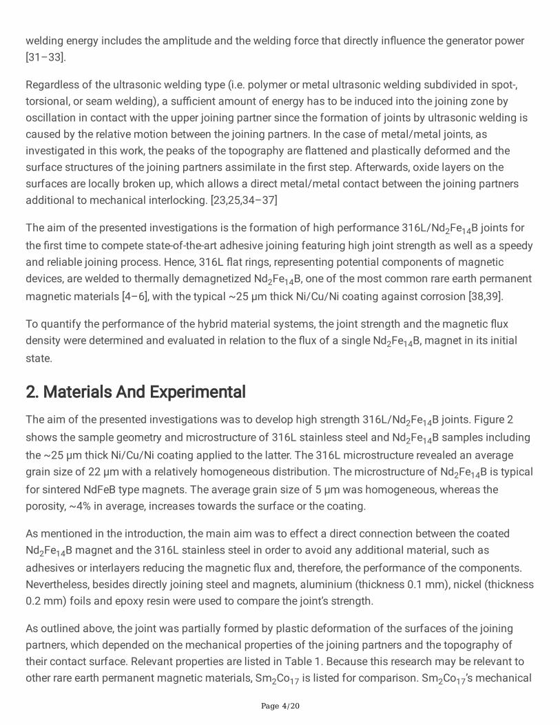
welding energy includes the amplitude and the welding force that directly in�uence the generator power[31–33].
Regardless of the ultrasonic welding type (i.e. polymer or metal ultrasonic welding subdivided in spot-,torsional, or seam welding), a su�cient amount of energy has to be induced into the joining zone byoscillation in contact with the upper joining partner since the formation of joints by ultrasonic welding iscaused by the relative motion between the joining partners. In the case of metal/metal joints, asinvestigated in this work, the peaks of the topography are �attened and plastically deformed and thesurface structures of the joining partners assimilate in the �rst step. Afterwards, oxide layers on thesurfaces are locally broken up, which allows a direct metal/metal contact between the joining partnersadditional to mechanical interlocking. [23,25,34–37]
The aim of the presented investigations is the formation of high performance 316L/Nd2Fe14B joints forthe �rst time to compete state-of-the-art adhesive joining featuring high joint strength as well as a speedyand reliable joining process. Hence, 316L �at rings, representing potential components of magneticdevices, are welded to thermally demagnetized Nd2Fe14B, one of the most common rare earth permanentmagnetic materials [4–6], with the typical ~25 µm thick Ni/Cu/Ni coating against corrosion [38,39].
To quantify the performance of the hybrid material systems, the joint strength and the magnetic �uxdensity were determined and evaluated in relation to the �ux of a single Nd2Fe14B, magnet in its initialstate.
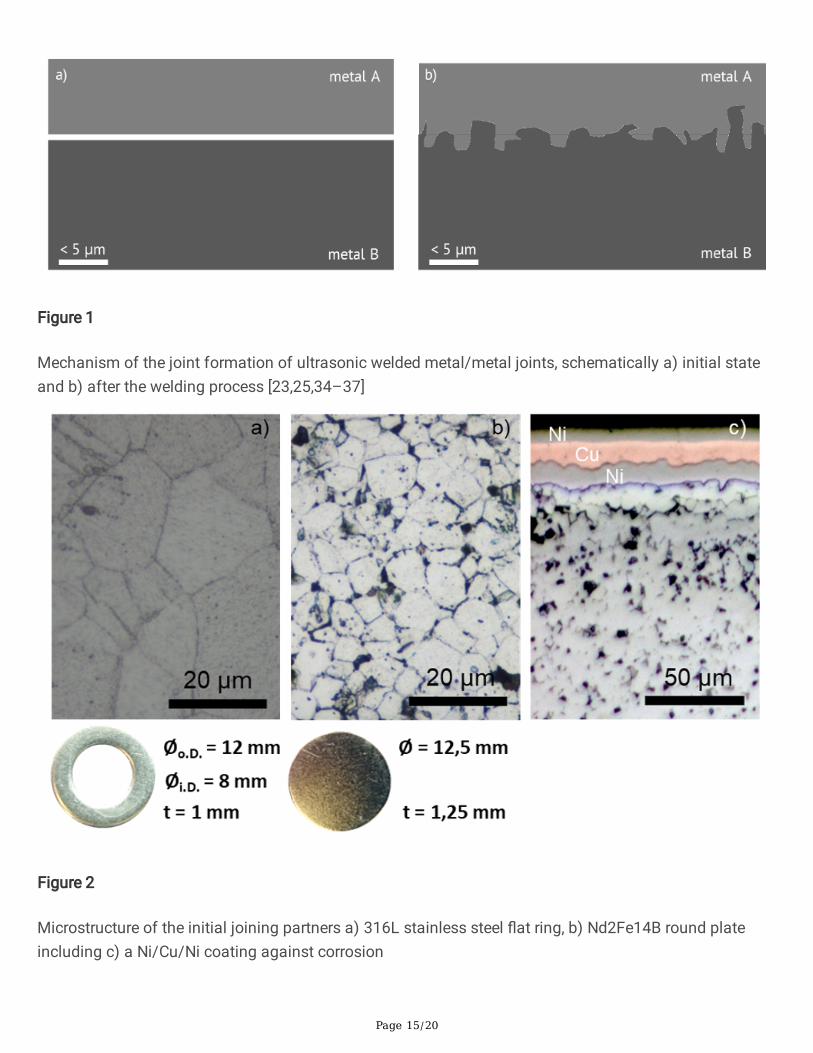
2. Materials And ExperimentalThe aim of the presented investigations was to develop high strength 316L/Nd2Fe14B joints. Figure 2shows the sample geometry and microstructure of 316L stainless steel and Nd2Fe14B samples includingthe ~25 µm thick Ni/Cu/Ni coating applied to the latter. The 316L microstructure revealed an averagegrain size of 22 µm with a relatively homogeneous distribution. The microstructure of Nd2Fe14B is typicalfor sintered NdFeB type magnets. The average grain size of 5 µm was homogeneous, whereas theporosity, ~4% in average, increases towards the surface or the coating.
As mentioned in the introduction, the main aim was to effect a direct connection between the coatedNd2Fe14B magnet and the 316L stainless steel in order to avoid any additional material, such asadhesives or interlayers reducing the magnetic �ux and, therefore, the performance of the components.Nevertheless, besides directly joining steel and magnets, aluminium (thickness 0.1 mm), nickel (thickness0.2 mm) foils and epoxy resin were used to compare the joint’s strength.
As outlined above, the joint was partially formed by plastic deformation of the surfaces of the joiningpartners, which depended on the mechanical properties of the joining partners and the topography oftheir contact surface. Relevant properties are listed in Table 1. Because this research may be relevant toother rare earth permanent magnetic materials, Sm2Co17 is listed for comparison. Sm2Co17’s mechanical
Page 5/20
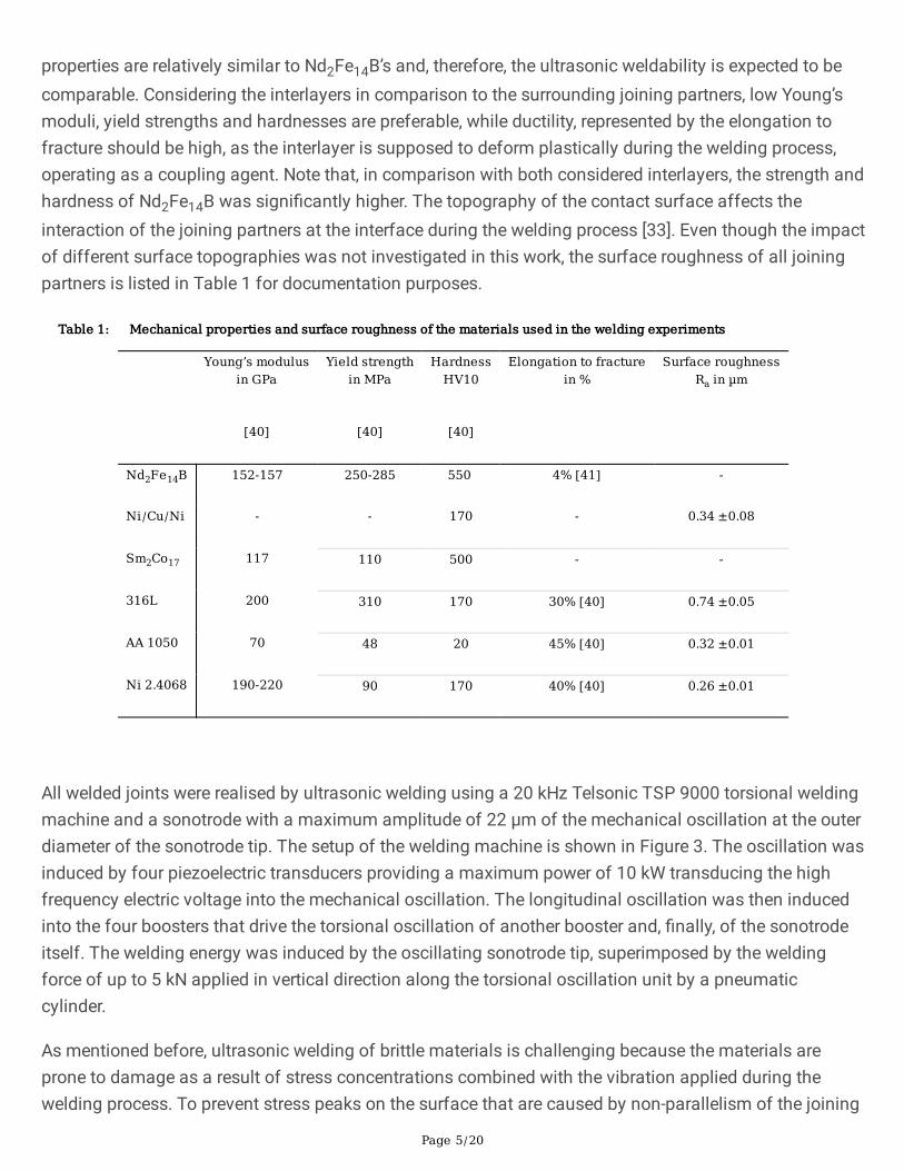
properties are relatively similar to Nd2Fe14B’s and, therefore, the ultrasonic weldability is expected to becomparable. Considering the interlayers in comparison to the surrounding joining partners, low Young’smoduli, yield strengths and hardnesses are preferable, while ductility, represented by the elongation tofracture should be high, as the interlayer is supposed to deform plastically during the welding process,operating as a coupling agent. Note that, in comparison with both considered interlayers, the strength andhardness of Nd2Fe14B was signi�cantly higher. The topography of the contact surface affects theinteraction of the joining partners at the interface during the welding process [33]. Even though the impactof different surface topographies was not investigated in this work, the surface roughness of all joiningpartners is listed in Table 1 for documentation purposes.
Table 1: Mechanical properties and surface roughness of the materials used in the welding experiments
Young’s modulusin GPa
Yield strengthin MPa
HardnessHV10
Elongation to fracturein %
Surface roughnessRa in µm
[40] [40] [40]
Nd2Fe14B 152-157 250-285 550 4% [41] -
Ni/Cu/Ni - - 170 - 0.34 ±0.08
Sm2Co17 117 110 500 - -
316L 200 310 170 30% [40] 0.74 ±0.05
AA 1050 70 48 20 45% [40] 0.32 ±0.01
Ni 2.4068 190-220 90 170 40% [40] 0.26 ±0.01
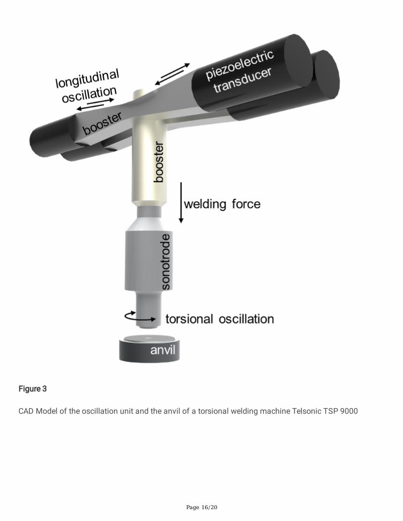
All welded joints were realised by ultrasonic welding using a 20 kHz Telsonic TSP 9000 torsional weldingmachine and a sonotrode with a maximum amplitude of 22 µm of the mechanical oscillation at the outerdiameter of the sonotrode tip. The setup of the welding machine is shown in Figure 3. The oscillation wasinduced by four piezoelectric transducers providing a maximum power of 10 kW transducing the highfrequency electric voltage into the mechanical oscillation. The longitudinal oscillation was then inducedinto the four boosters that drive the torsional oscillation of another booster and, �nally, of the sonotrodeitself. The welding energy was induced by the oscillating sonotrode tip, superimposed by the weldingforce of up to 5 kN applied in vertical direction along the torsional oscillation unit by a pneumaticcylinder.
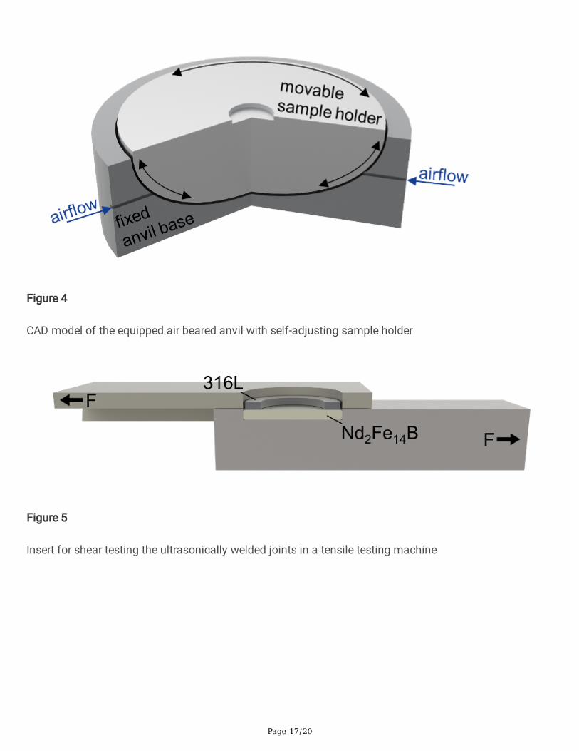
As mentioned before, ultrasonic welding of brittle materials is challenging because the materials areprone to damage as a result of stress concentrations combined with the vibration applied during thewelding process. To prevent stress peaks on the surface that are caused by non-parallelism of the joining

Page 6/20
partners and the sonotrode tip, an air beared anvil was used, which is shown in Figure 4. Compressed airstreams around the sample holder adjusting its tilt in relation to the sonotrode tip when a force is applied.The samples were placed in a groove in the centre of the sample holder to ensure that the weldingsamples and sonotrode tip were well centred. After cleaning with ethanol, all hybrid material systemswere joined with the 316L �at rings as upper and the NdFeB type magnets as lower joining partner.
Suitable process parameters determine the feasibility of joining at all and have a signi�cant impact onthe joint quality. The amplitude of the sonotrode oscillation, the welding energy and the welding pressureor welding force are the key process parameters that need to be adjusted dependent on the joiningpartners. The pro�le of the sonotrode tip is typically another important parameter, but is not in the focusof this work. The sonotrode used in this work had a �ne pyramidal structure.
The determination of process parameters is challenging as both, the amplitude and the welding pressureaffect the welding energy. In order to obtain a high joint strength, welding parameters were investigatedby a design of experiments (DoE) approach using the software Umetrics MODDE 7 to plan 24 processparameter setups with 4 repetitions for each setup in 2 blocks, i.e. 96 welding experiments in total. In thismodel the amplitude, the welding energy and the welding force are the factors to be varied in order toachieve a certain shear strength as response. The investigated parameter setups are determined by arandomized “center composite circumscribed” model (CCC) varying the amplitude from 12 to 15 µm, i.e.50-60% of the joining device’s capability, the welding energy from 40 to 250 J and the welding pressurefrom 0.05 to 2 bar, corresponding to welding forces between 80 and 1500 N, based on extensivepreliminary experiments.
Note that the welding amplitude was tuned by the power the generator provided to the piezoelectrictransducer and hence is indicated in both, % and µm. Furthermore, the welding force was tuned by airpressure attached to a pneumatic cylinder and therefore is indicated in both, bar and N. The relationbetween welding force and air pressure was determined by an independent force sensor.
For all parameter sets the welding time was below 1 second, showing the outstanding process speed,especially in comparison to adhesive joining techniques [42].
The process parameters were evaluated by the resulting joint strength, determined by shear tests. Theshear tests were performed with a 25 kN Schenk tensile testing machine, using a shear testing insert,which is illustrated in Figure 5. The joints are placed in a groove and sheared by the relative motion of theupper and the lower part of the insert, driven by the tensile testing machine with a crosshead speed of3 mm/min. To compare the shear strength of ultrasonically welded joints with and without ductile Ni- andAl-interlayers to state-of -the-art adhesive joining, epoxy resin was used to join six additional samples.
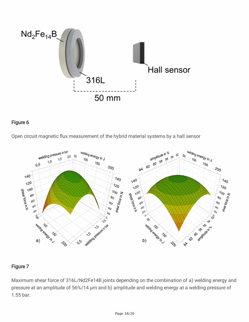
Measurements of the open circuit magnetic �ux density were performed by a hall sensor to determine thein�uence of the setup of the hybrid joints on the magnetic performance. The different thicknesses of thejoints were considered and balanced by a constant distance of 50 mm between the surface of themagnet and the sensor. The loss of magnetic �ux density of the hybrid material systems was determined
Page 7/20
in comparison to a single Nd2Fe14B magnet in its initial state. The setup of the magnetic measurementsis shown schematically in Figure 6 for a directly welded 316L/Nd2Fe14B as example.
3. Results And DiscussionThe in�uence of the parameter setups was investigated by DoE. The process parameters amplitude,welding pressure and welding energy were combined in order to maximize the resulting shear strength.The relation between the process parameters investigated and the resulting shear strength calculated bymultiple linear regression of the experimental results, is illustrated by the surface plots in Figure 7. Thecalculated maximum shear force is shown depending on the combination of a) welding energy andpressure at an amplitude of 56%/14 µm and of b) amplitude and welding energy at a welding pressure of1.55 bar.
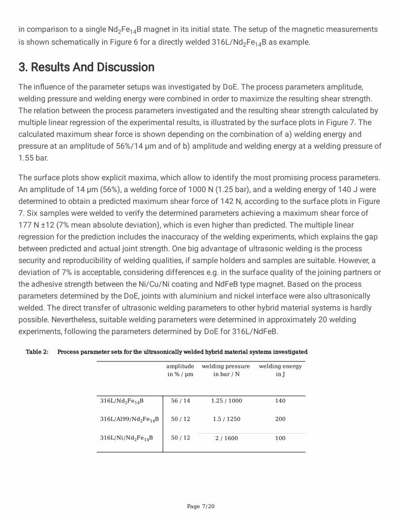
The surface plots show explicit maxima, which allow to identify the most promising process parameters.An amplitude of 14 µm (56%), a welding force of 1000 N (1.25 bar), and a welding energy of 140 J weredetermined to obtain a predicted maximum shear force of 142 N, according to the surface plots in Figure7. Six samples were welded to verify the determined parameters achieving a maximum shear force of177 N ±12 (7% mean absolute deviation), which is even higher than predicted. The multiple linearregression for the prediction includes the inaccuracy of the welding experiments, which explains the gapbetween predicted and actual joint strength. One big advantage of ultrasonic welding is the processsecurity and reproducibility of welding qualities, if sample holders and samples are suitable. However, adeviation of 7% is acceptable, considering differences e.g. in the surface quality of the joining partners orthe adhesive strength between the Ni/Cu/Ni coating and NdFeB type magnet. Based on the processparameters determined by the DoE, joints with aluminium and nickel interface were also ultrasonicallywelded. The direct transfer of ultrasonic welding parameters to other hybrid material systems is hardlypossible. Nevertheless, suitable welding parameters were determined in approximately 20 weldingexperiments, following the parameters determined by DoE for 316L/NdFeB.
Table 2: Process parameter sets for the ultrasonically welded hybrid material systems investigated
amplitudein % / µm
welding pressure in bar / N
welding energyin J
316L/Nd2Fe14B 56 / 14 1.25 / 1000 140
316L/Al99/Nd2Fe14B 50 / 12 1.5 / 1250 200
316L/Ni/Nd2Fe14B 50 / 12 2 / 1600 100
Page 8/20
An example of every ultrasonically welded hybrid material system (a), investigated in this work and therespective fracture surfaces of the joining partners after the shear test (b, c) is shown in Figure 8. Despitea slight sonotrode imprint, the 316L �at ring, the Nd2Fe14B round plate and the Ni/Cu/Ni coating as wellas the nickel foil do not appear to have been affected by the welding process. However, the aluminiumfoil warped up during welding. All samples failed at the 316L stainless steel interface with its joiningpartner.
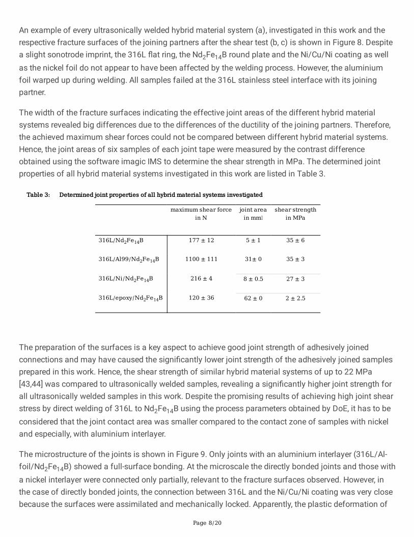
The width of the fracture surfaces indicating the effective joint areas of the different hybrid materialsystems revealed big differences due to the differences of the ductility of the joining partners. Therefore,the achieved maximum shear forces could not be compared between different hybrid material systems.Hence, the joint areas of six samples of each joint tape were measured by the contrast differenceobtained using the software imagic IMS to determine the shear strength in MPa. The determined jointproperties of all hybrid material systems investigated in this work are listed in Table 3.
Table 3: Determined joint properties of all hybrid material systems investigated
maximum shear forcein N
joint areain mm
shear strengthin MPa
316L/Nd2Fe14B 177 ± 12 5 ± 1 35 ± 6
316L/Al99/Nd2Fe14B 1100 ± 111 31± 0 35 ± 3
316L/Ni/Nd2Fe14B 216 ± 4 8 ± 0.5 27 ± 3
316L/epoxy/Nd2Fe14B 120 ± 36 62 ± 0 2 ± 2.5
The preparation of the surfaces is a key aspect to achieve good joint strength of adhesively joinedconnections and may have caused the signi�cantly lower joint strength of the adhesively joined samplesprepared in this work. Hence, the shear strength of similar hybrid material systems of up to 22 MPa[43,44] was compared to ultrasonically welded samples, revealing a signi�cantly higher joint strength forall ultrasonically welded samples in this work. Despite the promising results of achieving high joint shearstress by direct welding of 316L to Nd2Fe14B using the process parameters obtained by DoE, it has to beconsidered that the joint contact area was smaller compared to the contact zone of samples with nickeland especially, with aluminium interlayer.
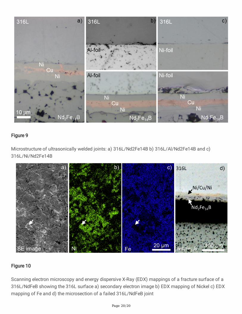
The microstructure of the joints is shown in Figure 9. Only joints with an aluminium interlayer (316L/Al-foil/Nd2Fe14B) showed a full-surface bonding. At the microscale the directly bonded joints and those witha nickel interlayer were connected only partially, relevant to the fracture surfaces observed. However, inthe case of directly bonded joints, the connection between 316L and the Ni/Cu/Ni coating was very closebecause the surfaces were assimilated and mechanically locked. Apparently, the plastic deformation of
Page 9/20
the Ni/Cu/Ni was so large that even the inner copper layer was deformed. In the case of joints with aninterlayer, only the outer Ni layer of the Ni/Cu/Ni-coating was plastically deformed to assimilate with thesurface of the other joining partner.
In the case of joints with an aluminium interlayer, the aluminium foil did assimilate with the Ni/Cu/Nicoating but signi�cantly less so with the surface of 316L in comparison to the directly welded samples.The nickel interlayer assimilated even less. In addition to the fact that the connection only occurredpartially, the nickel foil assimilated less with both the 316L and the Ni/Cu/Ni surfaces.
The fracture surfaces in Figure 8 show the failure of the hybrid material systems between the 316L �atrings and the joining partners. To further analyse the failure behaviour, all fracture surfaces wereinvestigated by scanning electron microscopy (SEM) and energy dispersive X-Ray (EDX) analysis. Allfracture surfaces included remaining material adherence of the opposite joining partner, which wasidenti�ed by EDX. This means, that the joints did not solely fail in the interlayer between the joiningpartners, but rather in the volume of the joining partners with lower shear strength. An example is shownfor a 316L/NdFeB joint in Figure 10, showing the fracture surface of 316L with remaining nickel clustersfrom the Ni/Cu/Ni coating of the magnet on the 316L �at ring. The related secondary electron (SE) image(Figure 10 a) shows the 316L surface. The arrows indicate one of the nickel clusters that remained aftershear testing the ultrasonically welded hybrid material systems as example, con�rmed by the highernickel and the lower iron concentration in the certain area, measured by EDX. Partially, the joints evenfailed in the volume of the magnet, shown in the microsection of a failed joint in Figure 10 d). Thenumerous nickel clusters that remained on the 316L �at ring after shear test and the failure in theNd2Fe14B volume explain the high joint strength caused by a connection on a microstructural level.
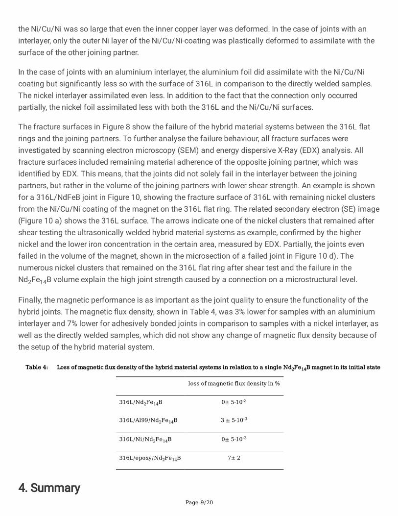
Finally, the magnetic performance is as important as the joint quality to ensure the functionality of thehybrid joints. The magnetic �ux density, shown in Table 4, was 3% lower for samples with an aluminiuminterlayer and 7% lower for adhesively bonded joints in comparison to samples with a nickel interlayer, aswell as the directly welded samples, which did not show any change of magnetic �ux density because ofthe setup of the hybrid material system.
Table 4: Loss of magnetic flux density of the hybrid material systems in relation to a single Nd2Fe14B magnet in its initial state
loss of magnetic flux density in %
316L/Nd2Fe14B 0± 5⋅10-3
316L/Al99/Nd2Fe14B 3 ± 5⋅10-3
316L/Ni/Nd2Fe14B 0± 5⋅10-3
316L/epoxy/Nd2Fe14B 7± 2
4. Summary

Page 10/20
Hybrid joints of 316L stainless steel and Nd2Fe14B rare earth permanent magnets were successfullyrealised by torsional ultrasonic welding. Three different joint material systems were investigated. Directlyjoined 316L stainless steel to Ni/Cu/Ni-coated demagnetized Nd2Fe14B (316L/Nd2Fe14B), and joints ofthe same materials with additional ductile aluminium and nickel interlayers (316L/Al/Nd2Fe14B and316L/Ni/Nd2Fe14B) were realised. A promising shear strength of 35 MPa for 316L/Nd2Fe14B and316L/Al/Nd2Fe14B was achieved as well as 27 MPa for 316L/Ni/Nd2Fe14B, which are signi�cantly higherin comparison to adhesively bonded joints. An observation of the microstructure revealed a direct contactbetween the joining partners, despite the less pronounced assimilation and interlocking of the surfaces incase of joints with aluminium and nickel interlayers. The magnetic performance, evaluated by magnetic�ux density of magnetized Nd2Fe14B, showed a slightly lower performance for 316L/Al/Nd2Fe14B jointscaused by the aluminium layer in the setup of the hybrid material system.
Despite the potential enhancement of the joint quality of the hybrid material systems investigated inrespect of the joint area, the results of this work indicate that ultrasonic welding is a promising techniquein order to enhance the production process and the performance of magnetic devices. Prospectiveinvestigations may include the in�uence of surface conditions of the joining partners, layer and interlayerthickness as well as the detailed analysis of the process parameters over the welding time.
5. DeclarationsAvailability of data and materials
The datasets used and analysed during the current study are available from the corresponding author onreasonable request.
Competing interests
The authors declare no competing �nancial interests.
Funding
This research received no speci�c grant from any funding agency in the public, commercial, or not-for-pro�t sectors.
Authors’ contributions
ML developed the process parameters for the ultrasonic welding experiments, analysed the joint quality,obtained the corresponding magnetic data and was the major contributor in writing the manuscript. MLand TB extensively discussed the results, as well as read and approved the manuscript.
Acknowledgement

Page 11/20
We thank our colleagues Benjamin Beck and Lars Greipl for their assistance on the welding experimentsand the shear testing of the welded samples. Gratitude is also expressed to Anna Julia Raupach andWolfgang Guth for their patience during the challenging preparation of the microsections. Sincere thanksalso go Dr. Matasha Mazis for proofreading.
References[1] J.M.D. Coey, Permanent magnet applications, Journal of Magnetism and Magnetic Materials 248(2002) 441–456. https://doi.org/10.1016/S0304-8853(02)00335-9.
[2] O. Gut�eisch, M.A. Willard, E. Brück, C.H. Chen, S.G. Sankar, J.P. Liu, Magnetic materials and devicesfor the 21st century: stronger, lighter, and more energy e�cient, Advanced materials (Deer�eld Beach, Fla.)23 (2011) 821–842. https://doi.org/10.1002/adma.201002180.
[3] J. Fischbacher, A. Kovacs, M. Gusenbauer, H. Oezelt, L. Exl, S. Bance, T. Schre�, Micromagnetics ofrare-earth e�cient permanent magnets, Journal of Physics D: Applied Physics 51 (2018) 193002.https://doi.org/10.1088/1361-6463/aab7d1.
[4] O. Gut�eisch, Controlling the properties of high energy density permanent magnetic materials bydifferent processing routes, Journal of Physics D: Applied Physics 33 (2000) R157-R172.https://doi.org/10.1088/0022-3727/33/17/201.
[5] M. Duerrschnabel, M. Yi, K. Uestuener, M. Liesegang, M. Katter, H.-J. Kleebe, B. Xu, O. Gut�eisch, L.Molina-Luna, Atomic structure and domain wall pinning in samarium-cobalt-based permanent magnets,Nature communications 8 (2017) 54. https://doi.org/10.1038/s41467-017-00059-9.
[6] W. Rodewald, B. Wall, M. Katter, K. Uestuener, Top Nd-Fe-B magnets with greater than 56 MGOe energydensity and 9.8 kOe coercivity, IEEE Trans. Magn. 38 (2002) 2955–2957.https://doi.org/10.1109/TMAG.2002.803075.
[7] M. Liesegang, R. Regnat, K. Uestuener, F.-J. Boergermann, M. Katter, In�uence of the Sample Positionon the Measured Magnetic Flux in Helmholtz Coils Biased with Halbach Array Systems, InternationalWorkshop on Rare-Earth and Future Permanent Magnets and their Applications, Darmstadt, 2016.
[8] M. Haavisto, S. Tuominen, T. Santa-Nokki, H. Kankaanpää, M. Paju, P. Ruuskanen, Magnetic Behaviorof Sintered NdFeB Magnets on a Long-Term Timescale. Advances in Materials Science and Engineering,2014, 1-7 (2014). https://doi.org/10.1155/2014/760584.
[9] R.S. Popovic, J.A. Flanagan, P.A. Besse, The future of magnetic sensors, Sensors and Actuators A:Physical 56 (1996) 39–55. https://doi.org/10.1016/0924-4247(96)01285-X.
[10] B. Chang, S. Bai, D. Du, H. Zhang, Y. Zhou, Studies on the micro-laser spot welding of an NdFeBpermanent magnet with a low carbon steel, Journal of Materials Processing Technology 210 (2010) 885–
Page 12/20
891. https://doi.org/10.1016/j.jmatprotec.2010.01.021.
[11] S.K. Gharghan, R. Nordin, M. Ismail, Energy-e�cient ZigBee-based wireless sensor network for trackbicycle performance monitoring, Sensors (Basel, Switzerland) 14 (2014) 15573–15592.https://doi.org/10.3390/s140815573.
[12] C. Schott, R. Racz, F. Betschart, R.S. Popovic, A new two-axis magnetic position sensor, in:Proceedings of IEEE Sensors, IEEE, 12-14 June 2002, pp. 911–915.
[13] H. Raich, P. Blümler, Design and construction of a dipolar Halbach array with a homogeneous �eldfrom identical bar magnets: NMR Mandhalas. Concepts in Magnetic Resonance Part B: MagneticResonance Engineering, 23B(1), 16-25 (2004). https://doi.org/10.1002/CMR.B.20018.
[14] K.S. Cho, Viscoelasticity of Polymers: Theory and Numerical Algorithms, 1st ed., SpringerNetherlands, Dordrecht, s.l., 2016.
[15] C.-W. Feng, C.-W. Keong, Y.-P. Hsueh, Y.-Y. Wang, H.-J. Sue, Modeling of long-term creep behavior ofstructural epoxy adhesives, International Journal of Adhesion and Adhesives 25 (2005) 427–436.https://doi.org/10.1016/j.ijadhadh.2004.11.009.
[16] W. Xi, W. Liu, R. Hu, Y. Yin, M. Yue, Property enhancement of bonded Nd-Fe-B magnets by compositeadhesive design, Materials & Design 192 (2020) 108767. https://doi.org/10.1016/j.matdes.2020.108767.
[17] I.F. Villegas, Strength development versus process data in ultrasonic welding of thermoplasticcomposites with �at energy directors and its application to the de�nition of optimum processingparameters, Composites Part A: Applied Science and Manufacturing 65 (2014) 27–37.https://doi.org/10.1016/j.compositesa.2014.05.019.
[18] G. Harman, J. Albers, The Ultrasonic Welding Mechanism as Applied to Aluminum-and Gold-WireBonding in Microelectronics, IEEE Trans. Parts, Hybrids, Packag. 13 (1977) 406–412.https://doi.org/10.1109/TPHP.1977.1135225.
[19] F. Staab, F. Balle, Ultrasonic torsion welding of ageing-resistant Al/CFRP joints: Properties,microstructure and joint formation, Ultrasonics 93 (2019) 139–144.https://doi.org/10.1016/j.ultras.2018.11.006.
[20] F. Balle, G. Wagner, D. Ei�er, Ultrasonic Metal Welding of Aluminium Sheets to Carbon FibreReinforced Thermoplastic Composites, Adv. Eng. Mater. 11 (2009) 35–39.https://doi.org/10.1002/adem.200800271.
[21] F. Balle, D. Ei�er, Statistical test planning for ultrasonic welding of dissimilar materials using theexample of aluminum-carbon �ber reinforced polymers (CFRP) joints, Mat.-wiss. u. Werkstofftech 43(2012) 286–292. https://doi.org/10.1002/mawe.201200943.

Page 13/20
[22] F. Staab, M. Liesegang, F. Balle, Local shear strength distribution of ultrasonically welded hybridAluminium to CFRP joints, Composite Structures 248 (2020) 112481.https://doi.org/10.1016/j.compstruct.2020.112481.
[23] J. Magin, F. Balle, Solid state joining of aluminum, titanium and their hybrids by ultrasonic torsionwelding, Mat.-wiss. u. Werkstofftech 45 (2014) 1072–1083. https://doi.org/10.1002/mawe.201400355.
[24] H.T. Fujii, Y. Goto, Y.S. Sato, H. Kokawa, Microstructure and lap shear strength of the weld interface inultrasonic welding of Al alloy to stainless steel, Scripta Materialia 116 (2016) 135–138.https://doi.org/10.1016/j.scriptamat.2016.02.004.
[25] S. Shimizu, H.T. Fujii, Y.S. Sato, H. Kokawa, M.R. Sriraman, S.S. Babu, Mechanism of weld formationduring very-high-power ultrasonic additive manufacturing of Al alloy 6061, Acta Materialia 74 (2014)234–243. https://doi.org/10.1016/j.actamat.2014.04.043.
[26] T. Watanabe, H. Sakuyama, A. Yanagisawa, Ultrasonic welding between mild steel sheet and Al–Mgalloy sheet, Journal of Materials Processing Technology 209 (2009) 5475–5480.https://doi.org/10.1016/j.jmatprotec.2009.05.006.
[27] V.K. Patel, S.D. Bhole, D.L. Chen, Ultrasonic spot welded AZ31 magnesium alloy: Microstructure,texture, and lap shear strength, Materials Science and Engineering: A 569 (2013) 78–85.https://doi.org/10.1016/j.msea.2013.01.042.
[28] A. Panteli, J.D. Robson, I. Brough, P.B. Prangnell, The effect of high strain rate deformation onintermetallic reaction during ultrasonic welding aluminium to magnesium, Materials Science andEngineering: A 556 (2012) 31–42. https://doi.org/10.1016/j.msea.2012.06.055.
[29] C. Born, H. Kuckert, G. Wagner, D. Ei�er, Ultrasonic Torsion Welding of Sheet Metals to CellularMetallic Materials, Adv. Eng. Mater. 5 (2003) 779–786. https://doi.org/10.1002/adem.200310102.
[30] H. Kuckert, C. Born, G. Wagner, D. Ei�er, Helium-tight Sealing of Glass with Metal by UltrasonicWelding, Adv. Eng. Mater. 3 (2001) 903. https://doi.org/10.1002/1527-2648(200111)3:11<903:AID-ADEM903>3.0.CO;2-O.
[31] B. Harras, K.C. Cole, T. Vu-Khanh, Optimization of the Ultrasonic Welding of PEEK-CarbonComposites, Journal of Reinforced Plastics and Composites 15 (1996) 174–182.https://doi.org/10.1177/073168449601500203.
[32] U. Khan, N.Z. Khan, J. Gulati, Ultrasonic Welding of Bi-Metals: Optimizing Process Parameters forMaximum Tensile-Shear Strength and Plasticity of Welds, Procedia Engineering 173 (2017) 1447–1454.https://doi.org/10.1016/j.proeng.2016.12.210.
[33] G. Wagner, F. Balle, D. Ei�er, Ultrasonic Welding of Aluminum Alloys to Fiber Reinforced Polymers,Adv. Eng. Mater. 15 (2013) 792–803. https://doi.org/10.1002/adem.201300043.

Page 14/20
[34] K.F. Graff, Process Applications of Power Ultrasonics - A Review, in: 1974 Ultrasonics Symposium,IEEE, 11.11.1974 - 14.11.1974, pp. 628–641.
[35] D. Bakavos, P.B. Prangnell, Mechanisms of joint and microstructure formation in high powerultrasonic spot welding 6111 aluminium automotive sheet, Materials Science and Engineering: A 527(2010) 6320–6334. https://doi.org/10.1016/j.msea.2010.06.038.
[36] M. Maeda, T. Sato, N. Inoue, D. Yagi, Y. Takahashi, Anomalous microstructure formed at the interfacebetween copper ribbon and tin-deposited copper plate by ultrasonic bonding, Microelectronics Reliability51 (2011) 130–136. https://doi.org/10.1016/j.microrel.2010.05.009.
[37] M. Maeda, Y. Takahashi, M. Fukuhara, X. Wang, A. Inoue, Ultrasonic bonding of Zr55Cu30Ni5Al10metallic glass, Materials Science and Engineering: B 148 (2008) 141–144.https://doi.org/10.1016/j.mseb.2007.09.028.
[38] Y.-S. Choi, Y.-H. Yoo, J.-G. Kim, S.-H. Kim, A comparison of the corrosion resistance of Cu–Ni–stainless steel multilayers used for EMI shielding, Surface and Coatings Technology 201 (2006) 3775–3782. https://doi.org/10.1016/j.surfcoat.2006.03.040.
[39] A. Ali, A. Ahmad, K.M. Deen, Multilayer ceramic coating for impeding corrosion of sintered NdFeBmagnets, Journal of Rare Earths 27 (2009) 1003–1007. https://doi.org/10.1016/S1002-0721(08)60357-9.
[40] Granta Design, CES Edupack, 2018.
[41] L. Li, A. Tirado, I.C. Nlebedim, O. Rios, B. Post, V. Kunc, R.R. Lowden, E. Lara-Curzio, R. Fredette, J.Ormerod, T.A. Lograsso, M.P. Paranthaman, Big Area Additive Manufacturing of High PerformanceBonded NdFeB Magnets, Scienti�c reports 6 (2016) 36212. https://doi.org/10.1038/srep36212.
[42] W. Brockmann, Adhesive bonding: Materials, applications and technology, Wiley-VCH, Weinheim,2009.
[43] S.L. Raykhere, P. Kumar, R.K. Singh, V. Parameswaran, Dynamic shear strength of adhesive jointsmade of metallic and composite adherents, Materials & Design 31 (2010) 2102–2109.https://doi.org/10.1016/j.matdes.2009.10.043.
[44] M. You, Y. Zheng, X.-L. Zheng, W.-J. Liu, Effect of metal as part of �llet on the tensile shear strength ofadhesively bonded single lap joints, International Journal of Adhesion and Adhesives 23 (2003) 365–369. https://doi.org/10.1016/S0143-7496(03)00064-2.
Figures
Page 15/20
Figure 1
Mechanism of the joint formation of ultrasonic welded metal/metal joints, schematically a) initial stateand b) after the welding process [23,25,34–37]
Figure 2
Microstructure of the initial joining partners a) 316L stainless steel �at ring, b) Nd2Fe14B round plateincluding c) a Ni/Cu/Ni coating against corrosion
Page 16/20
Figure 3
CAD Model of the oscillation unit and the anvil of a torsional welding machine Telsonic TSP 9000
Page 17/20
Figure 4
CAD model of the equipped air beared anvil with self-adjusting sample holder
Figure 5
Insert for shear testing the ultrasonically welded joints in a tensile testing machine
Page 18/20
Figure 6
Open circuit magnetic �ux measurement of the hybrid material systems by a hall sensor
Figure 7
Maximum shear force of 316L/Nd2Fe14B joints depending on the combination of a) welding energy andpressure at an amplitude of 56%/14 µm and b) amplitude and welding energy at a welding pressure of1.55 bar.

Page 19/20
Figure 8
Ultrasonically welded joints a) different hybrid material systems and fracture surfaces of b) the lowerjoining partner and c) the 316L �at ring
Page 20/20
Figure 9
Microstructure of ultrasonically welded joints: a) 316L/Nd2Fe14B b) 316L/Al/Nd2Fe14B and c)316L/Ni/Nd2Fe14B
Figure 10
Scanning electron microscopy and energy dispersive X-Ray (EDX) mappings of a fracture surface of a316L/NdFeB showing the 316L surface a) secondary electron image b) EDX mapping of Nickel c) EDXmapping of Fe and d) the microsection of a failed 316L/NdFeB joint