NCSX Pro/INTRALINK Users Guide · Drawings and models created using either the Pro/Engineer or...
40
NCSX Pro/INTRALINK Users Guide NCSX-GUID-PRO/INTR-00 May 4, 2005 Prepared by: _______________________________________ R. Simmons, NCSX Systems Engineering Support Manager Concurrences: ______________________________________ ______________________________________ T Brown, NCSX Design Integration J. Chrzanowski, Mechanical Design Manager Branch Head ______________________________________ J. Malsbury, NCSX QA Manager Approved by: ______________________________________ W. Reiersen, Engineering Manager
-
Upload
truonglien -
Category
Documents
-
view
225 -
download
0
Transcript of NCSX Pro/INTRALINK Users Guide · Drawings and models created using either the Pro/Engineer or...

NCSX Pro/INTRALINK Users Guide
NCSX-GUID-PRO/INTR-00
May 4, 2005
Prepared by: _______________________________________
R. Simmons, NCSX Systems Engineering Support Manager
Concurrences:
______________________________________ ______________________________________ T Brown, NCSX Design Integration J. Chrzanowski, Mechanical Design
Manager Branch Head
______________________________________
J. Malsbury, NCSX QA Manager
Approved by: ______________________________________ W. Reiersen, Engineering Manager

NCSX Pro/INTRALINK Users Guide
Pro/INTRALINK Users Guide Revision 0
i
Record of Revisions
Revision Date Description of Changes Rev 0 5/4/2005 Initial Issue
Table of Contents 1 INTRODUCTION ................................................................................................................................................1
1.1 OVERVIEW ...................................................................................................................................................1 1.2 APPLICABLE DOCUMENTS ........................................................................................................................2
2 PRO/INTRALINK OPERATION ......................................................................................................................2 2.1 DATA STORAGE AND CHANGE CONTROL PROCESSES ........................................................................2
2.1.1 Electrical Drawings................................................................................................................................2 2.1.2 Mechanical Models and Drawings.........................................................................................................2
2.2 USER ROLES AND AUTHORITY .................................................................................................................3 2.3 BASELINES....................................................................................................................................................5
2.3.1 Project Baselines vs. Pro/INTRALINK Baselines...................................................................................5 2.4 DRAWING NUMBERS...................................................................................................................................5
2.4.1 Versions vs. Revisions.............................................................................................................................5 2.4.2 Standardized Numbering Scheme...........................................................................................................5
2.4.2.1 General Numbering Scheme...............................................................................................................5 2.4.2.2 Mechanical Drawings .........................................................................................................................6 2.4.2.3 Electrical Drawings ............................................................................................................................6 2.4.2.4 Sketches..............................................................................................................................................6 2.4.2.5 Prototype Numbers .............................................................................................................................7 2.4.2.6 As-Built Numbers...............................................................................................................................7
2.5 DRAWING RELEASE SCHEME ...................................................................................................................8 2.6 CONFIGURATION CONTROL OF ELECTRONIC MODELS AND DRAWINGS......................................10
3 HOW TO RUN PRO/INTRALINK..................................................................................................................10 3.1 GETTING STARTED ...................................................................................................................................10 3.2 OPENING/CREATING A WORKSPACE ....................................................................................................12 3.3 OPENING THE COMMONSPACE ..............................................................................................................13 3.3 CHECKING OUT AN OBJECT ...................................................................................................................14 3.4 CHECKING IN AN OBJECT .......................................................................................................................16 3.5 RUNNING A PROGRAM .............................................................................................................................17 3.7 FROTOOLS..................................................................................................................................................18
4 PRO/INTRALINK DETAILS...........................................................................................................................18 4.1 PREVIEWING OBJECTS ............................................................................................................................18 4.2 SETTING OBJECT STATUS .......................................................................................................................19 4.3 ADDING FILES TO THE USER WORKSPACE AND PURGING FRAMES ...............................................19
5 USING RELEASE LEVELS .............................................................................................................................22 5.1 PROMOTING AND DEMOTING OBJECTS ...............................................................................................22 5.2 REQUESTING TO PROMOTE FORMS AND REPORTS ...........................................................................23
6 MISCELLANEOUS FEATURES.....................................................................................................................24 6.1 CONTENT DISPLAY FEATURE .................................................................................................................24 6.2 PRO LOCATE ..............................................................................................................................................25
ANNEX I .................................................................................................................................................................... I-1

NCSX Pro/INTRALINK Users Guide
Pro/INTRALINK Users Guide Revision 0
ii
ANNEX II ................................................................................................................................................................ II-1
Figures
Figure 2-1 Pro-INTRALINK Communications.........................................................................................................3 Figure 2-2 Commonspace Folders ..............................................................................................................................3 Figure 3-1 LOGIN and Application Menu...............................................................................................................11 Figure 3-2 Open/Create Workspace .........................................................................................................................12 Figure 3-3 Workspace Display ..................................................................................................................................13 Figure 3-4 Commonspace Display .............................................................................................................................13 Figure 3-5 Commonspace Icon Display Listing .......................................................................................................14 Figure 3-6 Commonspace Display Selecting an Object Being Checked Out ........................................................15 Figure 3-7 Commonspace Display Showing an Object Being Checked Out .........................................................15 Figure 3-8 Check-In Sequence Started.....................................................................................................................16 Figure 3-9 Check-In Sequence Completed...............................................................................................................17 Figure 3-10 Opening and Running an Object..........................................................................................................17 Figure 4-1 Object Information Report .....................................................................................................................19 Figure 4-2 Setting the Object Status.........................................................................................................................19 Figure 4-3 Creating New Objects..............................................................................................................................20 Figure 4-4 Import Dialog Window............................................................................................................................21 Figure 4-5 Frame Manager .......................................................................................................................................22 Figure 5-1 Promote/Demote Dialog Display.............................................................................................................23 Figure 5-2 Promote/Demote Form ............................................................................................................................23 Figure 6-1 Initial Content Display Window .............................................................................................................24 Figure 6-2 Second Content Display Window ...........................................................................................................24 Figure 6-3 First Step in Locate Process ....................................................................................................................25 Figure 6-4 Example of Locate Feature .....................................................................................................................26
Tables
Table 2-1 Pro/INTRALINK Roles ..............................................................................................................................4
NCSX Pro/INTRALINK Users Guide
Pro/INTRALINK Users Guide Revision 0
1
1 Introduction 1.1 Overview
The PPPL Central CADD Design Group is moving from hand created drawings to electronic drawings using a variety of PPPL-approved electronic drawing Computer Aided Design and Drawing (CADD) software packages. Currently two PPPL-approved CADD software packages are approved for use on the NCSX project. For mechanical and facilities, the 2D or 3D Pro/Engineer (Pro/E) software from Parametric Technology Corporation (PTC) is the standard. For electrical 2D drawings, the AUTOCAD software from AutoDesk, Incorporated is the standard. . Other CADD software may be used with prior approval of the NCSX Engineering Manager, after coordination with the Head, Engineering and Technical Infrastructure Department. In addition to electronic models and drawings, there exist a large number of legacy vellum and other hard copy medium drawings that represent legacy equipment and systems. New fusion experiments such as the National Compact Stellarator Experiment (NCSX) will most likely utilize existing legacy equipment, systems, and PPPL infrastructure to minimize the cost for these experiments. These drawings shall retain their original numbers and be maintained in the PPPL Central CADD Design Center. The PPPL Drafting Supervisor shall maintain control of these hard copy drawings. This Pro/INTRALINK Users Guide only addresses the development, review and approval, and storage requirements of electronic drawings and models. Drawings and models created using either the Pro/Engineer or AUTOCAD (or other approved CADD software) will reside electronically in the Pro/INTRALINK database. This Engineering Standard provides the basic primer on the operation of the Pro/INTRALINK database. This manual provides a basic primer in how to get started in running Pro/INTRALINK. The National Compact Stellarator Project (NCSX) will be the first project at PPPL to use Pro/INTRALINK as the data management system for storing drawings and models electronically. NCSX drawings and models will be prepared in these CADD programs in accordance with PPPL Engineering Design/Drafting Standard ES-DRFT-001 and Engineering Procedure ENG-010 “Control of Drawings, Software and Firmware”, with the exception that drawings developed by the applicable Oak Ridge National Laboratory shall have the ORNL title block. Specific details on how to utilize the CADD programs are contained in the operating instruction manuals that come with each respective CADD program.
Although other projects at PPPL may use the Pro/INTRALINK database, this Users Guide is specific to the NCSX Project and is divided into six sections. Section 1 is an overview introduction. Section 2 describes how Pro/INTRALINK controls, stores and manages data. Section 3 provides the detail of how to get to the user workspace and the central storage area, Commonspace. Section 4 provides some of the more important details of running Pro/INTRALINK. Section 5 provides the processes of promoting (and demoting) objects. Section 6 provides an overview of some miscellaneous functions available in Pro/INTRALINK.

NCSX Pro/INTRALINK Users Guide
Pro/INTRALINK Users Guide Revision 0
2
1.2 Applicable Documents
The latest revisions of the following documents support this Users Guide: Document Title
PPPL Engineering Standard ES-DRFT-001 Engineering Design/Drafting Standard PPPL ENG-010 Control of Drawings, Software, and Firmware NCSX-PLAN-CMP NCSX Configuration Management Plan NCSX-PROC-002 NCSX Configuration Control NCSX-PROC-005 NCSX Electronic Signatures NCSX-PROC-007 NCSX Electronic Model and Drawing/INTRALINK Processes NCSX-PROC-009 NCSX Request for Deviations
2 Pro/INTRALINK Operation 2.1 Data Storage and Change Control Processes
2.1.1 Electrical Drawings Electrical drawings created in AUTOCAD currently only utilize the storage capabilities of the Pro/INTRALINK database. Electrical drawings developed in AUTOCAD do not yet use the electronic review and approval processes inherent in the Pro/INTRALINK database; The initial review and approval processes for these 2D drawings is a manual process in that comments are generated and resolved manually. Only when the drawing is ready to be signed off will the drawings be converted to pdf and then approved using the NCSX Electronic signature procedures contained in NCSX-PROC-005. Both the source AUTOCAD and pdf drawings are stored within the Pro/INTRALINK database. Changes to electrical drawings are processed and managed via the procedures contained in NCSX Procedures that address configuration control (NCSX-PROC-002), the handling of electronic models and drawings (NCSX-PROC-007), and the processing of Requests for Deviation (NCSX-PROC-009).
2.1.2 Mechanical Models and Drawings The Pro/INTRALINK oracle data management tool is used to store and manage electronic data represented in mechanical models, drawings, and other detailed electronic information (e.g., assembly, part, data curve, spreadsheet, etc.) and format that is generated using Pro/E. The Pro/INTRALINK system provides the systems and processes for the storage of data and establishes an overall change control to process and govern control changes to models and drawings. Pro/INTRALINK provides communication between the Commonspace (or server) and the workspace database, as illustrated in Figure 2-1. Models, drawings will be stored in a folder structure within the central database called the Commonspace, which is the collection point for all design activities, accessible to all users. The Commonspace format will follow the project defined WBS structure The NCSX project Commonplace folder structure is shown in Figure 2-2. Each folder will have subfolders breaking down the second and third level WBS areas.
Pro/INTRALINK provides methods to manage objects and baselines stored within the Commonplace. The object is the basic building block of the Pro/INTRALINK database. A release scheme (2.5Section ) is used to establish the progression of an object through the design

NCSX Pro/INTRALINK Users Guide
Pro/INTRALINK Users Guide Revision 0
3
process. A Pro/INTRALINK baseline can be set to establish a fixed configuration of objects; Release procedures are used for authorization to promote objects to higher Release levels, and Roles are established to define user data access.
Commonspace
Workspace Workspace
User Workspace User Workspace
CommonspaceCommonspace
WorkspaceWorkspace WorkspaceWorkspace
User Workspace User Workspace
Figure 2-1 Pro-INTRALINK Communications
Figure 2-2 Commonspace Folders
2.2 User Roles and Authority User “Roles” are established to define what a user is able to do with a specific folder and with the objects stored within a folder. Actions can include: view only, object check out, deleting an object, creating folders, etc. Three groups of personnel have been identified with various access capabilities within Pro/INTRALINKdatabase system. These are:
• ADMIN – selected personnel authorized to perform administrative functions that alter the functions of Pro/INTRALINK. This is limited to PPPL Computer Division personnel.
• CADD – personnel authorized to develop and modify Pro/Engineer or AUTOCAD models and drawings. This is limited to personnel trained in the operation of Pro/Engineer and/or AUTOCAD.
• VIEWER – All personnel not in either the ADMIN or CADD groups. Personnel in this category have view only access giving them the ability to check out an object but not check in.

NCSX Pro/INTRALINK Users Guide
Pro/INTRALINK Users Guide Revision 0
4
Within the CADD Group, a further subdivision of user “roles” is established to define what a user is able to do with a specific folder and the models and/or drawings stored within a folder, no matter whether Pro/E or AUTOCAD generated. Five “roles” have been established for the NCSX project and the rights of these individuals are listed within the Pro/INTRALINK database. These five “roles” are listed below in descending order of capability to manipulate or change a model or drawing:
• Manager –This is the NCSX Pro/INTRALINK Manager(not the Project Manager). For the NCSX Project, this is the Design Integration Manger or designee – has full capability and can override the WBS Manager and the Designer;
• WBS Manager – the responsible WBS Manager or cognizant Project Engineer and/or Engineering Manager;
• Designer – responsible designer or engineer creating/modifying the drawing or model; • View Only – general view access and can copy the file into a personal workspace but
does not have the capability to return to the Commonspace; and • No Access – provides the ability to only view the object in the database – cannot copy or
remove from the Commonspace. For the NCSX Project, the established roles and authorities for these users are detailed in Table 2-1 below:
Table 2-1 Pro/INTRALINK Roles
OBJECT ACTIONS Manager WBS Manager Designer Viewer No AccessSet Revision x x xSet Release Level x x xSet Branch x x xEdit Non-Versioned Object x x xPromote Object x x xPackage x x xDemote Object x x xTransfer Review x x Modify Relationship x x xModify Object Attribute x x xOverride or Abort RTP x x Forced Check-In to different branch xCheck-In File x x xSubscribe x x xDelete Object xForced Check-In to same branch xCheck-Out x x x x
FOLDER ACTIONSDelete Non-Versioned Object x Create Branch x Edit Folder x Modify Non-Versioned Attribute x x xEdit Folder Authorization xCreate Non-Versioned Objects x x xEdit Non-Versioned Objects x x xMove Object xSet CS Status x x xRename Object x x xView Object x x x x x

NCSX Pro/INTRALINK Users Guide
Pro/INTRALINK Users Guide Revision 0
5
2.3 Baselines 2.3.1 Project Baselines vs. Pro/INTRALINK Baselines The latest version of the NCSX Project Execution Plan (PEP) defines the project Technical, Cost, and Schedule Baselines that provide the basis for performance measurement and tracking and configuration control. Within the Pro/INTRALINK terminology, the term baseline is also used. However, in this context, the Pro/INTRALINK baseline relates only to the Pro/INTRALINK database and how it relates to the NCSX Project Technical Baseline definition. A Pro/INTRALINK baseline is a fixed configuration of objects that can be created at anytime within Pro/INTRALINK. A formal project will set baselines that will freeze objects (models/drawings, etc.) at the start of a design review and those version numbers will be saved. Baselines can also be created at intermediate points of release. Baselines are created in the Commonspace as well as during a Check In or Promotion operation. When created, a unique name must be supplied. A number of operations can be performed on a baseline in the Commonspace: create, view, modify, move to a different folder location, rename, check out objects to workspace and interrogate. Baseline parameters can be set as: read only; read and add; read, add and delete. . 2.4 Drawing Numbers 2.4.1 Versions vs. Revisions It is also important at this point to distinguish between the Pro/INTRALINK “version” and “revision” number. Until a drawing is released for Fabrication, a “revision” number would not be assigned. Rather, the “version” number will be used to track the drawing’s evolution as changes are made through release levels up to the release fo fabrication level. The “version” number is the sequential extension that is automatically added to drawing number (starting at 01 and sequencing through number 99) and indexed by 1 after each change is made This “version” will carry through until such time that the particular drawing is released for Fabrication. Once a drawing is initially released for Fabrication, Revision 0 will be assigned and subsequent changes will be marked by an increase in the “revision” number. The design documentation for the NCSX Project will come under formal configuration control in a staged fashion. This process is outlined in the NCSX Configuration Management Plan and its accompanying implementing procedure. The Engineering Change Proposal (ECP) is the vehicle by which a revision to a baseline design document is approved. However, once the ECP is approved, as per PPPL Engineering Procedure 010, Control of Drawings, Software, and Firmware, an Engineering Change Notice (ECN) shall be used to effect changes to a drawing released for Fabrication.
2.4.2 Standardized Numbering Scheme 2.4.2.1 General Numbering Scheme A standardized drawing numbering scheme has been established for the NCSX Project. This Pro/INTRALINK Users Guide provides specific drawing numbering scheme formats. Generally, there will be several categories:

NCSX Pro/INTRALINK Users Guide
Pro/INTRALINK Users Guide Revision 0
6
• Sketch Numbers • Concept Numbers • Regular Drawing Numbers • Prototype Numbers • As-Built Numbers
For the NCSX Project, all drawing numbers will take a form that follows the NCSX WBS structure. A typical number during conceptual design might be S17E112-011; where S is the NCSX project designation, 17 defines the concept number, E the sheet size, a three level WBS breakdown (112) follows, then the drawing number (001). Concept numbers are generally sequential and are obtained by looking into the Commonspace to get the next sequential number, however, should the next sequential number not be selected, the ProE protocol in INTRALINK will prevent duplicate numbers. The concept number is only used during the developmental and conceptual design phase. After leaving the conceptual design phase of the project, the concept number designation (17 in this example) will be dropped, so that going forward the drawing number will be shortened to, SE112-011 in this example. Using the WBS drawing tree structure and Pro/INTRALINK, an engineer or designer can go into the Commonspace database and take the next available number (reserving a block of numbers is discouraged) within the NCSX folder where the drawing was started (saving the part to the Commonspace as the design progresses), or a temporary name can be used while developing the drawing on the Workspace. However, when the drawing is saved and returned to the Commonspace, the next available version will be assigned in the Commonspace. Pro/INTRALINK allows one and only one name within the database so there can be no duplications. 2.4.2.2 Mechanical Drawings
For NCSX mechanical drawings, drawing numbers –000 through –010 are saved for top-level assemblies. Drawing numbers –011 through –999 will be used for parts, assemblies or drawings with no preference to order (the next number is taken).
2.4.2.3 Electrical Drawings For NCSX electrical drawings developed in AUTOCAD, drawing numbers will be altered slightly by adding the letter “E” after the WBS number. This designation will also provide an easily distinguishable numbering scheme between mechanical and electrical drawings. Since electrical drawings don’t typically subdivide down into the parts or assembly level, there are no reserved numbers for electrical drawings. An electrical drawing number will take the form SB112E011 where S is the NCSX project designation, B the sheet size, 112 the WBS descriptor, E indicates an electrical drawing), and is followed by the drawing number (011). 2.4.2.4 Sketches Sketches numbers will be assigned for ideas still in the early developmental stages, and likely before a clear concept has developed. The usual sequence is for sketches to precede concept

NCSX Pro/INTRALINK Users Guide
Pro/INTRALINK Users Guide Revision 0
7
drawings. Preliminary sketch numbers that are assigned to a model or drawing shall be based on the NCSX WBS structure and take the following form:
• Mechanical Sketches - SB112-XXXXXX (no spaces). Where the first letter (S) designates the NCSX project; the letter “B” is the last initial of the user name (first and second initials can also be used); 112 define the first three WBS levels and –XXXXX can be a number or alphanumeric description of the object. Withing the Pro/INTRALINK database, a mechanical sketch file directory (000_sketch) has been established to allow all engineers/designers/drafters participating in the NCSX project to store mechanical sketch files. Should a sketch evolve into a design concept to be pursued, the sketch will be converted to a regular drawing using the numbering scheme outlined above.
• Electrical Sketches - SB144E-XXXXXX. Since electrical drawings are developed outside the Pro/INTRALINK database using AUTOCAD, the user may develop a sketch using the NCSX drawing scheme. In order to hold this drawing number within the Pro/INTRALINK database while the drawing/sketch is being developed, the AUTOCAD user will need to submit a text file with the name (e.g., SB144E-XXXX.txt to Pro/INTRALINK. After the AUTOCAD drawing is finished the file (named SB144E-XXXXXX.dwg) is placed in INTRALINK and the text file is moved to the INTRALINK folder “ZTRASH”. The INTRALINK Manager (NCSX Design Integration Manager) will remove objects in this folder at a later date.
2.4.2.5 Prototype Numbers Prototype numbers will only be assigned when the prototype model is not expected to represent the final production unit. Prototype models and drawings will have a special designation in the drawing number with the letter “P” added at the end of the standard number. This will allow the models and drawing of components that are to be fabricated as prototypes to take the same number as the baseline model except for the added letter “P” at the end. It is important to note that Prototype Released models and drawings represent a fabrication release and hence the Prototype Release of models will require the same degree of rigor of checking and sign-off as do drawings and models promoted to the Fabrication Release level. It is very unlikely that a prototype would eventually be designated as the first production unit since prototypes rarely have the same details and functionality of the production unit, however should this occur, a means of converting the prototype released drawing to a Fabrication Release drawing is accomplished by saving the drawing and then dropping the “P” from the numbering scheme and then saving as an entirely new drawing. 2.4.2.6 As-Built Numbers As-Built numbers are only assigned when the physical model needs to be changed to reflect that the final physical configuration in the field. The RLM will determine if as-built drawings will be required, based on an assessment of technical, cost, and schedule risks. If a physical change to the model is determined by the RLM to be required, a new drawing will be created with the letters “AB” placed at the end of the part model/drawing number to identify those parts and/or models that revised as-built parts. Top-level assembly models developed using Pro/Engineer will also be revised by replacing the standard part with the revised part that matched the features of the as-built part.

NCSX Pro/INTRALINK Users Guide
Pro/INTRALINK Users Guide Revision 0
8
Alternately, the RLM may decide that as-built drawings are not required. In this instance, the impacted drawing/model will simply be annotated with the NCR or RFD number to indicate a variance from plan. 2.5 Drawing Release Scheme Within the Pro/INTRALINK environment, a defined set of “release” levels has been defined that a drawing or model will progress through. Generally, the release levels are closely tied to the design review process – drawings and models are promoted in preparation for a design review. In some instances, however, the change may be so significant that the drawing or model will be promoted independent of the design review. Although six release levels were originally established for the NCSX Project and remain for regular drawings (sketches and concept drawings are not included in this release scheme), in practice only two release levels are utilized:
• Work in Progress; and • Fabrication.
The other potential release levels (Conceptual Design, Preliminary Design, Prototype, and Final Design) were established early in the Project and are available, but are no longer utilized. For each drawing, the Design Integration Manager establishes the appropriate release scheme that defines who needs to check and sign off on drawings before final release for fabrication. This is based on the specific design details being shown on the drawing, the availability of reviewers, etc. While generic release schemes have been developed that define the majority of situations, the Design Integration Manager has the ability to customize release schemes (e.g., for drawings having no welding details, there is no need for Welding Engineer approval). It is not necessary that an object pass though each release level. For example, a prototype approved drawing or model may go from prototype release to release for fabrication without proceeding through final design if it is determined that the prototype will become the first production article. However, should this occur, the prototype drawing or model will need to be converted to a release for fabrication drawing with its own unique (and different) drawing number as a Revision 0 drawing or model. Each Pro/INTRALINK folder will have a predefined set of release procedures that identifies who can approve an object to allow it to pass to the next release level. On the NCSX project the WBS Manager or Cognizant Engineer directly involved with the component design process will determine when a model or drawing should be proposed for promotion and whether the full release scheme should be followed or if a subgroup for the WBS section under his/her responsibility will suffice. The NCSX project release procedure starts with the designer (or drafter) promoting the object followed by sequential approvals made by the Cognizant Engineer, the WBS manager, Design Integration manager and finally the section Project Engineer.
Release procedures specify an approval process that occurs when an object is promoted or demoted to a designated release level. As work progresses and a designated milestone is reached, an authorized user can move a drawing, model, or other object from one release level of Pro/INTRALINK to higher level by promoting it. Likewise an object can be moved back to a lower level by demoting it. When a user tries to move an object, the associated release procedure

NCSX Pro/INTRALINK Users Guide
Pro/INTRALINK Users Guide Revision 0
9
is initiated. A release procedure request is sent to those users who have been designated as reviewers for the procedure. For the NCSX project the promotion process can be completed with approvals made by the cognizant WBS Manager and Project Engineer, based on a predefined set of release procedures established for each WBS area. Annex I to this plan provides sample screen shots of the drawing release process. Annex II provides sample screen shots of the promotion process.
For the NCSX Project, the following release sequence is typical:
• All new models and drawings will start in the Work in Progress release level from which they can be promoted to a higher level. It is not necessary that the progression be to the next release level. The standard sequence is Conceptual Design release to Preliminary Design Release to Final Design Release to Fabrication Release. However, this can be changed with the approval of the Engineering Manager. Also if a change is needed to be made in a model or drawing previously released (say for Preliminary Design) it must be “demoted” and placed in the Work in Progress Release level where modifications are made and then again promoted to a higher Release level.
• Models and drawings used for the Project Conceptual Design Review (CDR) are all archived at the Conceptual Design Release level with a unique name assigned. These constitute the Project’s CDR Baseline of drawings, which is NOT allowed to change. Copies of these models and drawings can be demoted to Work in Progress Release level in order to modify them as the design matures or promote them to a higher release level in preparation for a preliminary design review.
• Prior to the Preliminary Design Review of specific subsystems, those drawings describing these subsystem will be promoted to the Preliminary Design (PD) release level and the resulting PDR baseline will be frozen and archived. This set of drawings (comprised of drawings promoted to PD level and, most likely, other drawings at a lower level of promotion, will constitute the Project’s PDR Baseline with a unique name assigned. Once the PDR Baseline is set, it is frozen and cannot be changes (in the same fashion as the CDR Baseline of drawings .
• Following the completion of the Preliminary Design Review (PDR), models and drawings requiring changes will be demoted back to a Work in Progress status . Once these changes have been made, the impacted models and drawings will be re-promoted to the Preliminary Design Release level. In the NCSX Configuration Control Program, documents and drawings typically come under formal configuration control processes at the completion of the PDR. Accordingly, upon successful incorporation of the PDR comments any additional changes will require an Engineering Change Proposal (ECP) to effect the change. However, until a drawing is released for Fabrication, the ECN process described in PPPL Engineering Procedure ENG-010 will not apply. As other PDRs are conducted, the same process will occur, eventually culminating in an updated Preliminary Design Baseline representing the Project’s technical baseline at any point in time.
• If prototype components are to be fabricated, copies of the detailed design models and drawings will be released to the Prototype Release level. A prototype number will be placed on these objects. Prototype drawings releases will undergo the same rigor of checking, sign-off, and configuration control as do drawings and models released for

NCSX Pro/INTRALINK Users Guide
Pro/INTRALINK Users Guide Revision 0
10
Fabrication. If a determination is made that the prototype will become the first production article, the prototype drawing or model will be promoted to a Fabrication Release level (skipping Final Design) and a new drawing number assigned.
• For standard objects (not becoming a prototype) after the successful completion of the Final Design Review the models and drawings will be promoted to the Final Design Release level.
As procurement packages are assembled, models and drawings will be released to the Fabrication level. Only at this level will revisions be tracked. Pro/INTRALINK version numbers will be used to track early stages in the release process and these version numbers will be critical to understanding the exact set of drawings and models that are archived as a Project Technical Baseline. They will identify baselines, design milestones and the status of the object. As such version numbers need to be maintained for documentation purposes. The Pro/INTRALINK system administrator will not purge version numbers in any of the NCSX folders without consent of the NCSX Project Design Integration Group.
2.6 Configuration Control of Electronic Models and Drawings As with hard copy drawings, electronic models and drawings will require the same degree of discipline and review prior to approval. Electrical drawings are processed manually and, only after all changes have been resolved, will the drawing be converted to pdf format for signature by reviewers and the approving official (generally, the PPPL Drafting Supervisor or his designee.
Reviewers are identified either by the Drafting Supervisor (electrical drawings generated using AUTOCAD) or the Design Integration Manager (mechanical models, drawings, parts, and assemblies generated using Pro/E) in consultation with the Cognizant Engineer. Mechanical models and drawings generated using Pro/E fully utilize the electronic review and approval processes inherent in the Pro/INTRALINK database, but the electrical drawings generated in AUTOCAD do this process manually. The PPPL Engineering Drafting/CAD Guidelines and Standards (ES)DRFT-001) and NCSX-PROC-007 on the NCSX Electronic Model and Drawing/INTRALINK Processes provide guidelines and procedures for who has to review/check the impacted models and drawings and what to check for..
For mechanical models and drawings generated by Pro/E, the Pro/INTRALINK database ensures that each required step above is achieved prior to model and drawing approval. Models will only be approved electronically whereas drawings will be converted to pdf format and electronically assigned.
For both electrical and mechanical models and drawings, once an electronic model or drawing has been promoted and approved to a Release for Fabrication status, an ECP and accompanying ECN will be required to revise the model and/or drawing (NCSX-PLAN-CMP).
3 How to Run Pro/INTRALINK 3.1 Getting Started Pro/INTRALINK is started by clicking on the shortcut icon sitting on the user’s computer desktop. An Application Menu will appear with the menu items all grayed out except for the

NCSX Pro/INTRALINK Users Guide
Pro/INTRALINK Users Guide Revision 0
11
Login symbol. Clicking the Login symbol will result in a second window appearing - Figure 3-1, upper view. This second window is expanded out in Figure 3-1, lower view.
Figure 3-1 LOGIN and Application Menu
The User then enters his user name, password and selects OK. For first time users the password will be the user’s last name. The Application Menu will show all activities highlighted. Application menu includes the following:
Commonspace – Provides a central storage area where all design information is located. The central computer is located in the PPPL computer room. Workspace – This is the personal workspace located on a user’s computer where an individual manages his or hers own design work.
Administration – Allows Pro/INTRALINK administrators to configure the entire system. Locate – Allows users to search for objects in the Commonspace.
Preferences – Provides tools to allow users to configure the Workspace environment and tools for the administrators to develop system wide preferences that apply to all users. Purge – Allows administrators and authorized users to delete objects in the Commonspace.
Pending RTP Forms – Shows pending “Request to Promote” (RTP) forms needing action by authorized personnel. Exit – Used to shut down the user Pro/INTRALINK session.

NCSX Pro/INTRALINK Users Guide
Pro/INTRALINK Users Guide Revision 0
12
3.2 Opening/Creating a Workspace The first thing to select from the Application Menu when starting Pro/INTRALINK for the first time is the Workspace. This will enable the user to create a new Workspace on their computer or activate a Workspace created at some earlier time. The user can have many Workspaces but only one can be activated at a given time. The physical location of the Workspace on the user’s computer is normally at the following path location: C:\ptc\.proi\XXX, where XXX will be the name of the Workspace. The specific path may be different on a user’s machine but the important folder to look for is identified by the extension “.proi”. All Workspaces are below it.
To open or create a new Workspace the user should click the Workspace icon in the Application Menu and a second pull down window will appear. This is displayed in Figure 3-2. To create a new Workspace the user should activate the Create New Workspace indicator and type in the name of the Workspace. To open an existing Workspace the user should activate the Open Existing Workspace indicator and use the pull down window to show all existing Workspaces. The user should select the desired Workspace and then press OK. Note that there can be no space between letters or words that define an object (or Workspace). Objects include Pro/E, AUTOCAD, Excel or Word documents (or other objects) stored in Pro/INTRALINK. Use an underscore “_” to separate words.
.
Figure 3-2 Open/Create Workspace
The Workspace will open with all icons grayed out as shown in Figure 3-3 (back view). The user should then activate INTRALINK by selecting the icon “Intralink.” This will result in a second drop-down menu appearing as shown in Figure 3-3 (front view).

NCSX Pro/INTRALINK Users Guide
Pro/INTRALINK Users Guide Revision 0
13
Figure 3-3 Workspace Display
3.3 Opening the Commonspace The Commonspace can be opened directly from the Application Menu or from within the Workspace folder as shown in Figure 3-3. When activated either through the Application Menu or from the Workspace the Commonspace display will appear as shown in Figure 3-4:
Figure 3-4 Commonspace Display
Across the top of the Commonspace display, a series of icon tabs can be selected to activate different functions. The description of each icon tab is detailed in Figure 3-5.

NCSX Pro/INTRALINK Users Guide
Pro/INTRALINK Users Guide Revision 0
14
Refres
h
Add B
ookm
arkChe
ck O
utM
odify
Info
rmati
onDele
te
Add to
Brie
fcase
Table
Con
figur
ation
Refres
h
Add B
ookm
arkChe
ck O
utM
odify
Info
rmati
onDele
te
Add to
Brie
fcase
Table
Con
figur
ation
Family
Tab
le Rep
ort
Author
izatio
n Rep
ort
CS Rela
tions
hip re
port
BOM R
epor
tW
here
Used R
epor
t
Baseli
ne R
epor
t
Object
Histor
yOpe
n CS
Wind
ow
RTP R
epor
t
Open W
ork S
pace
Wind
ow
Open L
ocate
Wind
owOpe
n Pref
erenc
es W
indow
Pend
ing R
TP F
orms
Open L
ogin
Dialog
Open H
elp
Family
Tab
le Rep
ort
Author
izatio
n Rep
ort
CS Rela
tions
hip re
port
BOM R
epor
tW
here
Used R
epor
t
Baseli
ne R
epor
t
Object
Histor
yOpe
n CS
Wind
ow
RTP R
epor
t
Open W
ork S
pace
Wind
ow
Open L
ocate
Wind
owOpe
n Pref
erenc
es W
indow
Pend
ing R
TP F
orms
Open L
ogin
Dialog
Open H
elp
Figure 3-5 Commonspace Icon Display Listing
The Root Folder Structure is shown on the left side of the Commonspace display, showing all projects currently stored within Pro/INTRALINK at PPPL. In addition, there are several other useful folders:
The Library folder that contains Pro/Engineer hardware items as family tables (bolts, nuts, screws, washers, conflat flanges, etc.) that can be used in developing a pro/Engineer assembly For the NCSX Project, Request to Promote (RTP) and NCSX History folders have also been established. The Request to Promote folder is used to store NCSX project request forms. The NCSX History folder provides NCSX users access to the NCSX CDR data.
At the bottom of the Commonspace display are a series of tabs to provide further information. At PPPL, the most important “buttons” are the:
Latest Versions – list the latest versions of all the drawings in Pro/INTRALINK Baselines – can be used to list the various baselines (e.g., CDR, PDR, etc.) of a project if so desired Folder Info – provides information on the folder selected such as the name, the creator, when created, etc.
3.3 Checking Out an Object To check out an object (i.e., moving a copy of an object out of the Commonspace to the Work Place to permit manipulations/changes being made) from the Commonspace, the user should first open the folder within which the object is located. Most INTRALINK commands require that the user first select an object before starting the action.
For first time users, a folder named Pilot has been set up where first time users can check out and check in objects for practice. For the NCSX Project, new users have also been given a View Only

NCSX Pro/INTRALINK Users Guide
Pro/INTRALINK Users Guide Revision 0
15
role that will allow them to view and check out objects from the NCSX_History folder, providing access to the NCSX CDR data. Figure 3-6shows the Commonspace display from the Pilot folder and the Pro/Engineer object cube.part, highlighted for checking out to a Workspace.
Figure 3-6 Commonspace Display Selecting an Object Being Checked Out
A tab displayed at the top can be used to check out objects or a right click on the mouse (with the curser placed on the highlighted object) will open up a display window showing options that can be performed. If one slides the curser down to Checkout the check out process will proceed and the Checkout window shown in Figure 3-7 will appear.
Use pull down window to set Workspace
Use pull down window to set Workspace
Figure 3-7 Commonspace Display Showing an Object Being Checked Out
The Checkout window has been set up for standard check out of objects. If an assembly is to be checked out and there are drawings that are of interest, the user can check the box in the upper

NCSX Pro/INTRALINK Users Guide
Pro/INTRALINK Users Guide Revision 0
16
left hand corner that states “Include Drawings”. For those advanced users that would like to extract instances of a family table then the “Include Instances” box needs to be checked. It also should be noted that if a drawing is desired the object to be checked out, the drawing should be selected and, for Pro/Engineer developed drawings, Pro/INTRALINK would update the table to include all the parts or assemblies needed to make the drawing. To continue the check out process the user must specify the Checkout Options as indicated at the left of the Checkout display. A local enhanced picture is shown in the center of the Checkout display. Next to the “To:” place the curser and a list of Workspaces will be shown. Select the desired one. Local Copy has been set as default value, do not change it. When this is finished select OK. Another Checkout display will appear stating that Checkout is Complete and state how many objects have been checked out. Select OK in the Checkout Complete display.
3.4 Checking In an Object The check-in Sequence starts in the Workspace by the user highlighting those files that are to be checked into the Commonspace. The user can check-in individual objects or a full set of objects. Before an object can be checked-in there must be a folder designation that defines where the object will be filed within the Commonspace. Figure 3-8 and Figure 3-9 shows a typical object Check-In process. Figure 3-8 shows the Modify Attributes feature opened and a new Pro/Engineer object has been highlighted. The pull down window has been expanded to highlight “Folder”. When this is done a window shown in Figure 3-9 (upper section) will appear with the Root Folder shown in the center region. The user should expand the Root Folder to find the exact subfolder in the Root Folder where he would like the object placed. After the desired folder has been highlighted, the user should select apply and then OK. The name of the folder will be listed in one of the columns of Figure 3-8. Sometime the user will need to scroll the columns to the right to see it. Another thing that should be done is to add a description if one does not exist. Alternatively, the Modify Attributes feature also can be used to accomplish this. The user should select the item “Description” and type the description in the window to the right and select Apply.
Check In SequencePull down to select Folder
Figure 3-8 Check-In Sequence Started

NCSX Pro/INTRALINK Users Guide
Pro/INTRALINK Users Guide Revision 0
17
Pull down to select the Folder where the object will be placed
Expand to find the exact sub folder in the Root Folder
Say Apply and then OK
Figure 3-9 Check-In Sequence Completed
3.5 Running a Program To run Pro/Engineer, AUTOCAD or other documents (Word, PDF file, etc.) the following actions can be taken by the user:
• Right click on the object to highlight it.
• Right click the mouse to open the drop down box.
• Left click on Open to start the file
Figure 3-10 pictorially displays this process.
Figure 3-10 Opening and Running an Object

NCSX Pro/INTRALINK Users Guide
Pro/INTRALINK Users Guide Revision 0
18
The Object display tab can also be used to access the Open function. It must be noted that the user must have the opening software on their computer to run the application. For Pro/Engineer users it is often better to open Pro/Engineer first using the Intralink tab and then open the desired object. This allows the user to open the object as a simplified representative when dealing with a very large assembly.
3.7 FroTools FroTools is a browser based program that enables personnel not having direct access to Pro/Engineer (Pro/E) or do not have in-depth familiarity with how to navigate the Pro/INTRALINK database to relatively easily access and copy CAD files to their desktop. If used correctly, Fro/Tools will provide easy web access to the Pro/INTRALINK database. While FroTools has the capability to access other formats such as native ProE, DXF, IGES, etc. files, the NCSX Project’s use of FroTools is limited to accessing electronically signed pdf drawings. NCSX Procedure NCSX-PROC-011 provides more details on the use of FroTools to access the Pro/INTRALINK database.
4 Pro/INTRALINK Details 4.1 Previewing Objects Within the Commonspace or Workspace the user can view general information about an object if it has been created using Pro/Engineer. The example of this operation is shown in Figure 4-1. The user should highlight the Pro/Engineer object of interest and then depress the Object Information Report icon (fifth one from the left) at the top to the display. The solid model shown on the right hand side can then be expanded by clicking on the drop down arrow located in the upper right hand side of the solid model picture. After this is done the model will reappear at the center of the screen. In addition, the user can expand the size of the object by grabbing the corners of the picture and dragging the object larger. The model can be manipulated with a three-button mouse by dragging the mouse while holding the Ctrl key down, as the left (or middle) mouse buttons is depressed.

NCSX Pro/INTRALINK Users Guide
Pro/INTRALINK Users Guide Revision 0
19
Figure 4-1 Object Information Report
4.2 Setting Object Status When working in a concurrent engineering environment that involves a number of users it is important that users protect the objects being worked on so that others do not inadvertently make modifications. Two status symbols can be set on an object: Locked or Intent to Modify. Status symbols can be set either in a Workspace or the Commonspace.
The person who locked them can only modify locked objects. It is recommended that users lock objects to be modified when checking out of the Commonspace. All users can view a locked object but they cannot check in a revised object with a Locked symbol. With Intent to Modify symbol placed on an object other users are notified by the symbol that an object is in the process of being modified. However, other users can place revised objects back into the Commonspace. It is recommended that users lock objects to be modified when checking out of the Commonspace. Figure 4-2 shows two display windows. The window in the background is a the Commonspace window that has an object highlighted with the right mouse button depressed and the curser selecting the Change Status option clicked. The Change Status display is shown as an overlay where the “Lock” key has been depressed. The Status Description has been highlighted to indicate the outcome of a Locked process. In the spirit of cooperation it is important that objects are Unlocked after being modified and placed back in the Commonspace.
Object can be Locked, Unlocked or set with an “intent to Modify” Status.
Figure 4-2 Setting the Object Status
4.3 Adding Files to the User Workspace and Purging Frames There are a number of ways to add files to the Workspace. Once they are in the workspace they can be made accessible to other users by checking them back into the Commonspace. It should
NCSX Pro/INTRALINK Users Guide
Pro/INTRALINK Users Guide Revision 0
20
be noted that if the intent is to use the Pro/INTRALINK data management process for tracking changes made to an object (the object version number is incremented at each save), then all changes made to the object must be made while operating within Pro/INTRALINK. This involves Pro/Engineering parts and drawings, AUTOCAD drawings and any other project documents that have been placed under configuration control.
The following defines three ways to add files to a user workspace:
• Create a new object within a workspace.
• Migrate files from the operating system directly into a workspace.
• Copy existing Pro/INTRALINK objects and use them as the basis for a new design or document.
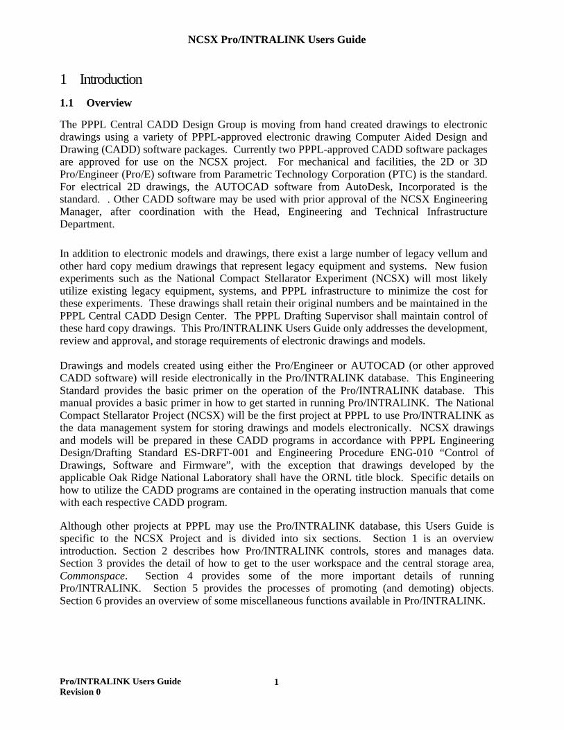
Creating a new object within a workspace can be accomplished by clicking the Object icon at the top of the Workspace menu as illustrated in Figure 4-3. By clicking the icon on New the Create New Object drop down window will open where the user can scroll the list to find file types of interest. Other than Excel and AUTOCAD, many of the files on the list deals with Pro/Engineer. The user should take a look and see if there is anything of interest. To complete the process a name is typed in the Object Name box and another drop down window is opened where “Root Folder” is shown. The user should then click the arrow at the right side of the Folder box and all folders located in the Root Folder will be presented. The user can then navigate within the folder structure and select the folder where the new object will be placed.
Figure 4-3 Creating New Objects
The user can import objects from the local directory of the computer by clicking the Object icon (Figure 4-3) and then moving the cursor down to and clicking Import. An Import Dialog display shown in Figure 4-4 will then open. The user can then move within the folder structure located in the “Folder” window and select the folder of interest. All objects located in the

NCSX Pro/INTRALINK Users Guide
Pro/INTRALINK Users Guide Revision 0
21
selected folder will be shown. The user should select the object desired for importing and hit OK.
Figure 4-4 Import Dialog Window
For Pro/Engineer users, clicking the Save As option allows the user to save a copy of a Pro/Engineer model to store it in our workspace. The object can be renamed at the same time.
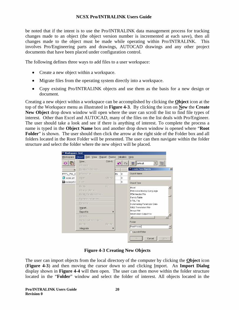
Every time an object is saved a new “frame” is created. The Frame Manager allows the user to purge frames or move to an earlier saved frame. The user can purge all frames except the last one, or define what will be the active frame, allowing the user to go back to an earlier state. The system administrators have set the maximum number of frames at 25, beyond which the highest number will be automatically purged. Purging a frame permanently deletes the object versions that were in the frame from the user computer. The user cannot undo a purge. Figure 3.5 shows a dialog window with the Frame display activated and the Frame drop down window opened. If the user clicks on the middle line (below Delete Object), the check mark will move to that line and, if Pro/Engineer part cube.prt was opened (the part that was being working on), the state of the object that existed at that time will be presented. If the user were to purge then all frames behind the check mark would be erased.
NCSX Pro/INTRALINK Users Guide
Pro/INTRALINK Users Guide Revision 0
22
Figure 4-5 Frame Manager
5 Using Release Levels As discussed in Section 2, release level attributes can be used to represent the different stages of an object as it moves through the design process. The NCSX project will be the first project at PPPL to use the Release process of Pro/INTRALINK that combines users, groups, roles and release levels to provide control over the design technical database.
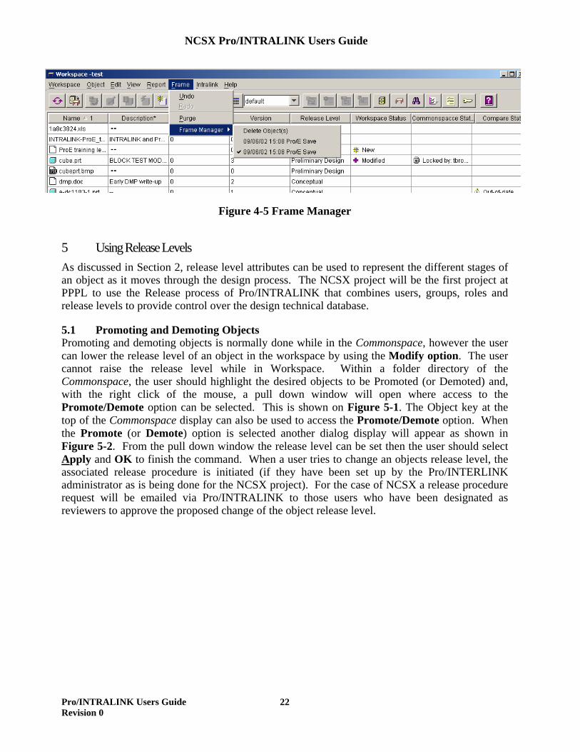
5.1 Promoting and Demoting Objects Promoting and demoting objects is normally done while in the Commonspace, however the user can lower the release level of an object in the workspace by using the Modify option. The user cannot raise the release level while in Workspace. Within a folder directory of the Commonspace, the user should highlight the desired objects to be Promoted (or Demoted) and, with the right click of the mouse, a pull down window will open where access to the Promote/Demote option can be selected. This is shown on Figure 5-1. The Object key at the top of the Commonspace display can also be used to access the Promote/Demote option. When the Promote (or Demote) option is selected another dialog display will appear as shown in Figure 5-2. From the pull down window the release level can be set then the user should select Apply and OK to finish the command. When a user tries to change an objects release level, the associated release procedure is initiated (if they have been set up by the Pro/INTERLINK administrator as is being done for the NCSX project). For the case of NCSX a release procedure request will be emailed via Pro/INTRALINK to those users who have been designated as reviewers to approve the proposed change of the object release level.

NCSX Pro/INTRALINK Users Guide
Pro/INTRALINK Users Guide Revision 0
23
Figure 5-1 Promote/Demote Dialog Display
Select Release Level then hit “Apply” and OK.
Figure 5-2 Promote/Demote Form
5.2 Requesting to Promote Forms and Reports For those reviewers designated to review drawings and documents it is important to check the Pending RTP Forms tab when the user first logging into Pro/INTRALINK. The RTP tab is shown on the Login and Application Menu (Figure 3-1). The voters see a message that there are pending requests when they log into Pro/INTRALINK. After reviewing the drawing or document requested the reviewer accepts or rejects the object along with adding comments. The

NCSX Pro/INTRALINK Users Guide
Pro/INTRALINK Users Guide Revision 0
24
approval can be transfer to another user for approval or be overwritten by Request to Promote Forms and Reports.
Annexes I and II to this plan provides more detail on promoting and signing drawings models and drawings. NCSX Procedure NCSX-PROC-005 provides additional guidance on signing electronic models and drawings.
6 Miscellaneous Features 6.1 Content Display Feature Content display settings should be set when first opening the Commonspace to “cs_display” to view a more complete set of Content displays. Figure 6-1 shows the location of this drop down window. To the left of the drop down window is the Table Configuration tab (shown in Figure 5.2). Selecting this tab a user can custom his/her display defining the columns, sort order and filter that are desired. A configuration name can be given to store the display for future reference.
Figure 6-1 Initial Content Display Window
Figure 6-2 Second Content Display Window

NCSX Pro/INTRALINK Users Guide
Pro/INTRALINK Users Guide Revision 0
25
6.2 Pro Locate Pro Locate is a tool used for locating information in the Commonspace based on different attributes, including the object name or description. The user should launch the Locate application by clicking the Locate Application tab on the Login Application Menu shown in Figure 3-1. The display shown in Figure 6-3 will appear where the user should first select the Attribute, say Description* and then open the drop down window. The * character can be used to indicate a series of letters. The user should then type in the search description and left click in the open space. VACUUM* was typed in this example. To make sure that description will be displayed, the user should open the pull down window and select cs_display as shown in Figure 6-4. Finally the user should select “+” to activate the search. All search values are case-sensitive, so the user must type the user values using the proper uppercase or lowercase values. The Locate window enables the user to run searches, create new searches, edit a saved search, and delete a saved search.
Open drop down window.
Type in search description.
Select attribute
Left click in open space.
Open drop down window.
Type in search description.
Select attribute
Left click in open space.
Figure 6-3 First Step in Locate Process

NCSX Pro/INTRALINK Users Guide
Pro/INTRALINK Users Guide Revision 0
26
Select cs_display
Select +
VACUUM* objects found in search. Figure 6-4 Example of Locate Feature

NCSX Pro/INTRALINK Users Guide
Pro/INTRALINK Users Guide Revision 0
ANNEXES

NCSX Pro/INTRALINK Users Guide
Pro/INTRALINK Users Guide Revision 0
ANNEX I - 1
ANNEX I Model and Drawing Release and Promotion
Within INTRALINK a Release Procedure is used to set the approval and notification list for a drawing package that will be promoted to Fabrication.
To find out about the promotion details left click on an object to highlight it and then right click to bring up a second dialog box.
Then select Information.

NCSX Pro/INTRALINK Users Guide
Pro/INTRALINK Users Guide Revision 0
ANNEX I -2
Highlight Request to Promote and RTF Forms
To review the Request to Promote history
With the RTP info tab selected the details of the Request to Promote action is provided (see below).
Select the RTP Objects tabs to obtain further info (see next slide).

NCSX Pro/INTRALINK Users Guide
Pro/INTRALINK Users Guide Revision 0
ANNEX I -3
After the drawing package is approved in INTRALINK PDF files are made for signatures.
Adobe Acrobat electronic signatures
Drawing package
Voters
Approval details can be found by selecting the RTP Object tab at the bottom

NCSX Pro/INTRALINK Users Guide
Pro/INTRALINK Users Guide Revision 0
ANNEX I -4
Revised drawings are electronically signed with initials placed in the revision block section of the drawing.
Electronic Sign-Off by Drafting
• Mechanical Drawings – Since the checker, weld engineer, other
reviewers (as appropriate), and Cognizant Engineer have already “signed” the Pro/E drawing within INTRALINK, only the Drafting Supervisor or his designee will electronically sign the pdf drawings (after verifying that all appropriate personnel have “signed” within INTRALINK.
• Electrical Drawings – Since the INTRALINK processes are not yet used for electrical drawings, the pdf drawing will have to be electronically signed by each reviewer.

NCSX Pro/INTRALINK Users Guide
Pro/INTRALINK Users Guide Revision 0
ANNEX I -5
The Electronic “Fab” Stamp
The Adobe Acrobat electronic signature will go here.
The drawing security is set:
1
2 set to Standard Security
3 set to 128-bit encryption
4 set to form fill-in or signing
5 Close
Under File

NCSX Pro/INTRALINK Users Guide
Pro/INTRALINK Users Guide Revision 0
ANNEX I -6
Place stamp on ALL sheets (if multi-sheet drawing)
Sample Drawing
1 select Form Tool
3 place a “1” in Name
4 select OK
2 drag cross-hair to create signature box
Add Signature Block
Sample Drawing

NCSX Pro/INTRALINK Users Guide
Pro/INTRALINK Users Guide Revision 0
ANNEX I -7
Add the signature box to all stamp regions on all sheets.
1 select the Hand Tool
2 Place the hand over signature area and right click.
3 Inter password and add reason for signing
4 select Save
Sample Drawing

NCSX Pro/INTRALINK Users Guide
Pro/INTRALINK Users Guide Revision 0
ANNEX I -8
After ONE sheet is signed all sheets will automatically receive a signature.
Sample Drawing
The drawing is saved automatically
Note: This is the security key
Sample Drawing

NCSX Pro/INTRALINK Users Guide
Pro/INTRALINK Users Guide Revision 0
ANNEX I -9
If the security key is opened and set to “Show Signatures”, a side column will open providing signature details.
Sample Drawing
When this PDF drawing file is reopened NOTHINGcan be deleted (stamp included) since it was placed there by the document owner.
Sample Drawing

Pro/INTRALINK Users Guide Revision 0
ANNEX II-1
ANNEX II Request to Promote Form and Process
1) select Options and add a description
2) select the release level and hit Apply and OK2) select the release level and hit Apply and OK