NCHRP Project 3-88 Guidelines for Ramp and Interchange...
79
NCHRP Project 3-88/Report 687: Guidelines for Ramp and Interchange Spacing TRB Webinar December 14, 2011 Moderator: Michael Ereti, City of Houston
Transcript of NCHRP Project 3-88 Guidelines for Ramp and Interchange...
NCHRP Project 3-88/Report 687: Guidelines for Ramp and Interchange Spacing
TRB Webinar
December 14, 2011
Moderator: Michael Ereti, City of Houston

Webinar Overview
Project Introduction – Brian Ray
Guidelines – Brian Ray
Traffic Operations Work Plan – Pete Jenior
Case Studies: Traffic Operations Focus – Pete Jenior
Safety Work Plan – R.J. Porter
Case Studies: Safety and Signing Focus – R.J. Porter
Closing Remarks– Brian Ray
Questions - All

Project Overview
Team
– Kittelson & Associates, Inc. (Prime): Brian Ray, Jim Schoen, Pete Jenior, Julia Knudsen, Shaun Quayle, Alex Kiheri
– Subs: University of Utah (R. J. Porter), Joel Leisch, John Mason, Roger Roess, and Traffic Research & Analysis
Schedule
– June 2008 to December 2010
Final Products
Available on-line
Project Introduction
Identify factors that influence ramp and interchange spacing needs:
– Geometric Design
– Traffic Operations
– Safety
– Signing
Conduct operations and safety research
Develop Guidelines for ramp and interchange spacing
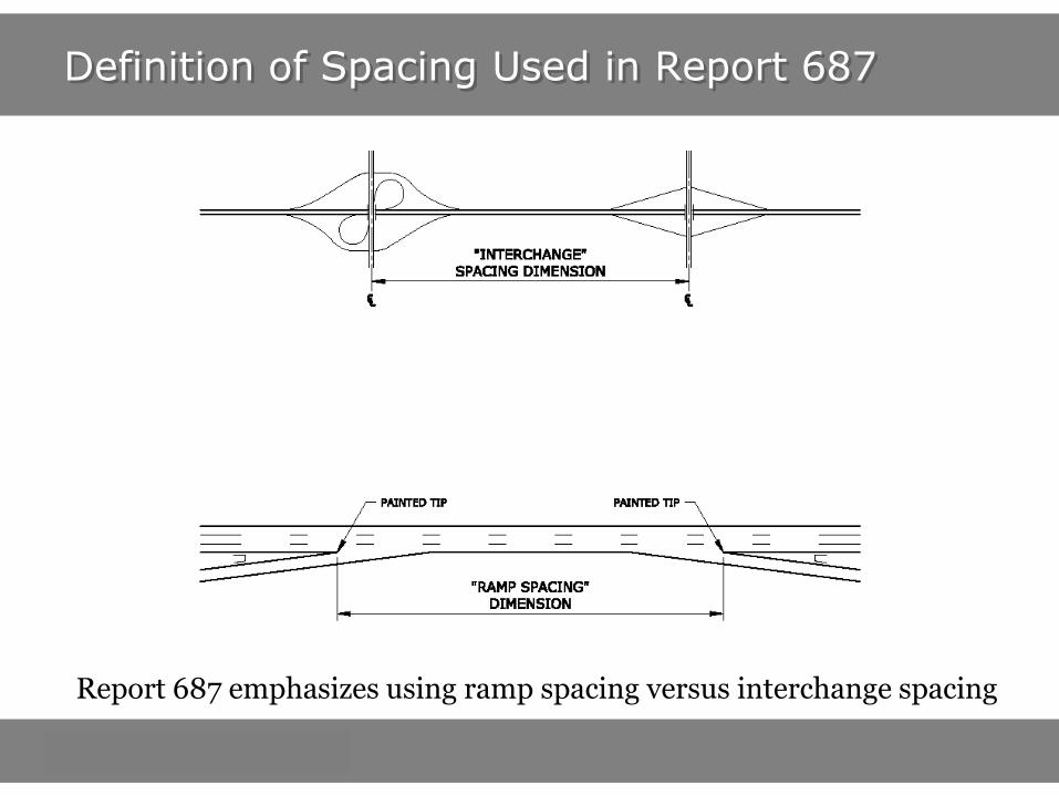
Definition of Spacing Used in Report 687
Report 687 emphasizes using ramp spacing versus interchange spacing

Current Spacing Guidelines
Guidance in 2004 AASHTO Green Book on ramp spacing:
Guidance in AASHTO Green Book on interchange spacing: 1 mile urban, 2 miles rural

Origins of Current Guidelines
Origins of current AASHTO Policy spacing guidance date to beginning of Interstate Highway era
Early studies examined trade-offs
– Access to freeway versus mobility/performance of freeway
– Performance of freeway versus performance of arterials
Interchange Spacing Guidance
– AASHTO Green Book (since 1984): 1 mile in urban areas, 2 miles in rural areas
– Some states recommended longer spacings than this
Ramp Spacing Guidance
– AASHTO Green Book (since 1984) guidance based upon table on following slide
– Dimensions are measured between “like points”
– Previous AASHTO Policies (Red and Blue Books) offered other spacing dimensions

Origins of Current Guidelines
Jack Leisch. Region 2 AASHTO Operating Committee on Design. 1975
Became Green Book Values

Guidelines
Chapter 1 – Introduction
Chapter 2 – Ramp and Interchange Spacing Overview
Chapter 3 – Design and Signing Considerations
Chapter 4 – Operational and Safety Considerations
Chapter 5 – Spacing Guidance
Chapter 6 – Scenario-Based Case Studies
References
Appendix A – Traffic Operations Tools
Guidelines - Principles
Avoid “one size fits all” spacing values
Customize spacing recommendations based on factors that affect ramp and interchange context
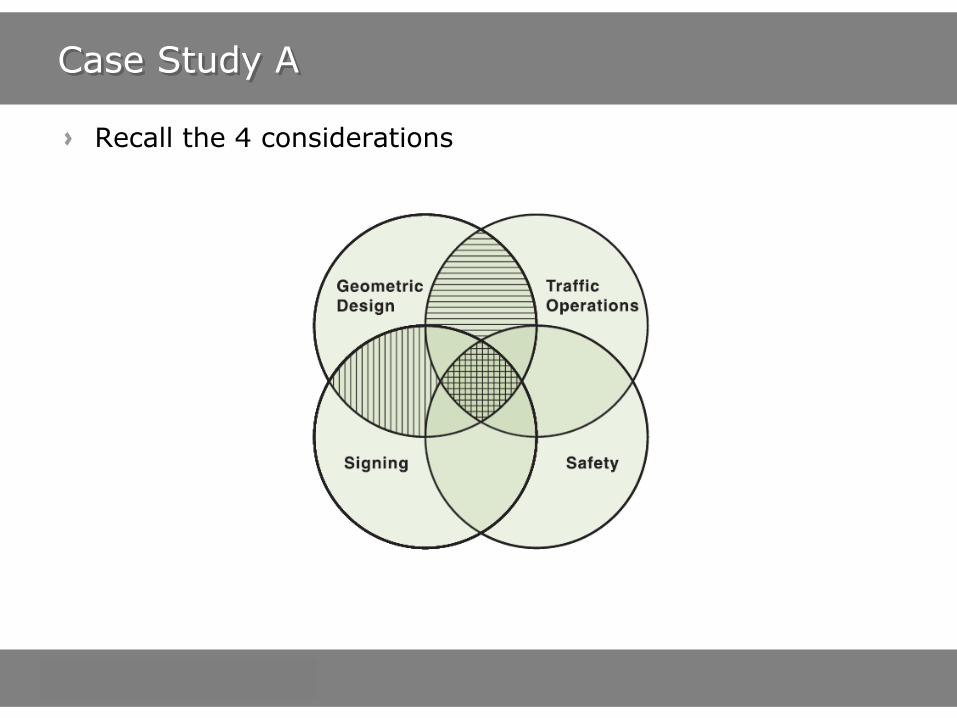
Systematic approach that considers
– Geometric design
– Traffic operations
– Safety
– Signing
Focus on ramp spacing
Deemphasize interchange spacing

Guidelines Framework
Understand the project context
Consider ramp spacing at the earliest stages (including signing)
Opportunities to affect spacing diminishes as design progresses
Apply appropriate tools at the right time

Guidelines – Chapter 5 (Spacing Guidance)
Consider each of these four elements when assessing ramp spacing

Spacing Guidance
Minimum ramp spacing needs based up geometry vary due to differences in:
– Traffic volumes
– Multi lane ramps
– Interchange form
– Terrain
– Agency standards and preferences
– Interchange configuration
Values recommended by Report 687 offer flexibility
Terminal locations impact spacing!
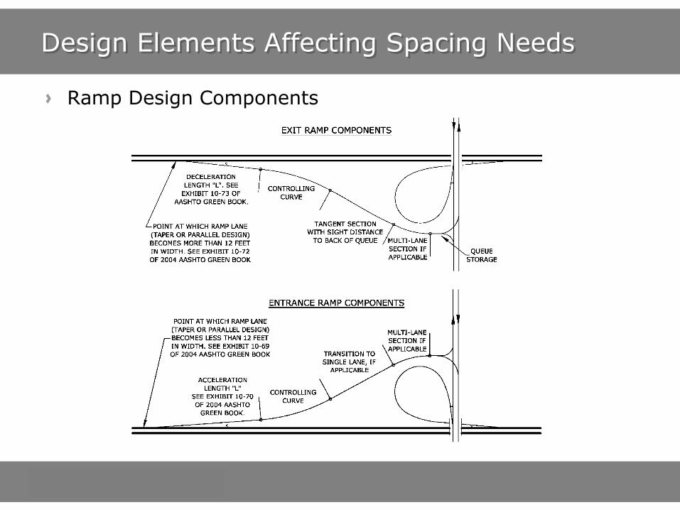
Design Elements Affecting Spacing Needs
Ramp Design Components

Design Elements Affecting Spacing Needs
Single entrance (or exit) versus double entrance design

Design Elements Affecting Spacing Needs
Turning Roadways
– Convergence Angle
Same turning roadway spacing but a vastly different entrance terminal location

Design Elements Affecting Spacing Needs
Sight Distance Needs

Spacing Guidance - Geometry
So, with design elements, traffic operations, safety considerations, and
signing considerations, what is minimum spacing?
It depends, but…
We can make some
assumptions
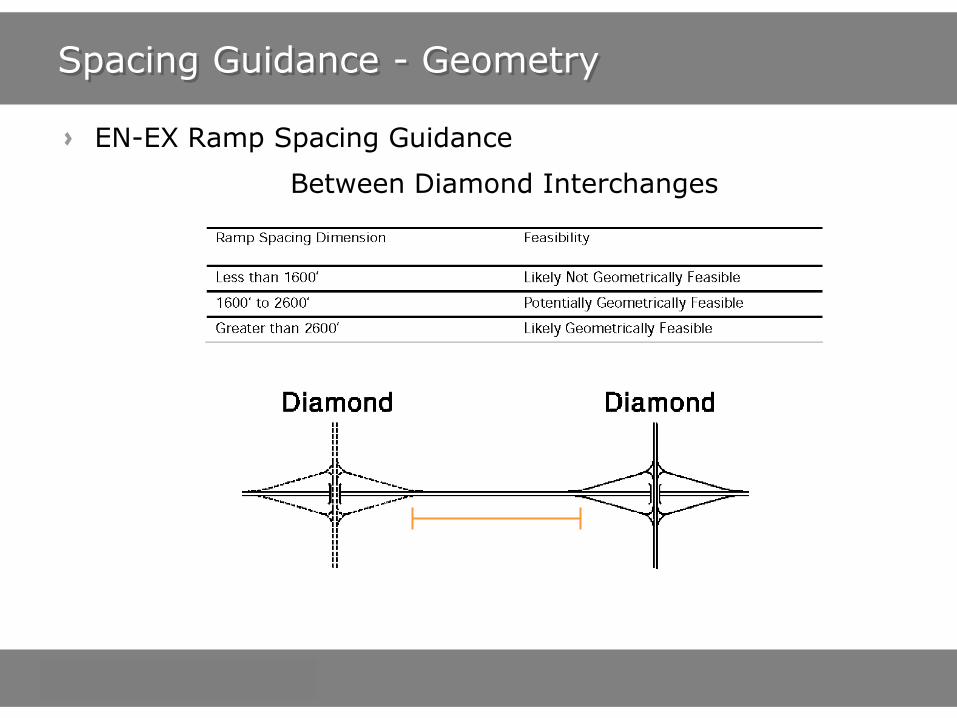
Spacing Guidance - Geometry
EN-EX Ramp Spacing Guidance
Between Diamond Interchanges

Spacing Guidance - Geometry
EN-EX Ramp Spacing Guidance
Between Partial Cloverleaf Interchanges

Spacing Guidance - Geometry
From ramp spacing guidance and knowledge of design components, interchange spacing can be inferred
Source: ITE Freeway and Interchange Geometric Design Handbook

Spacing Guidance - Geometry
Interchange Spacing GEOMETRIC DESIGN Feasibility
Use with caution! Consider your specific project context.
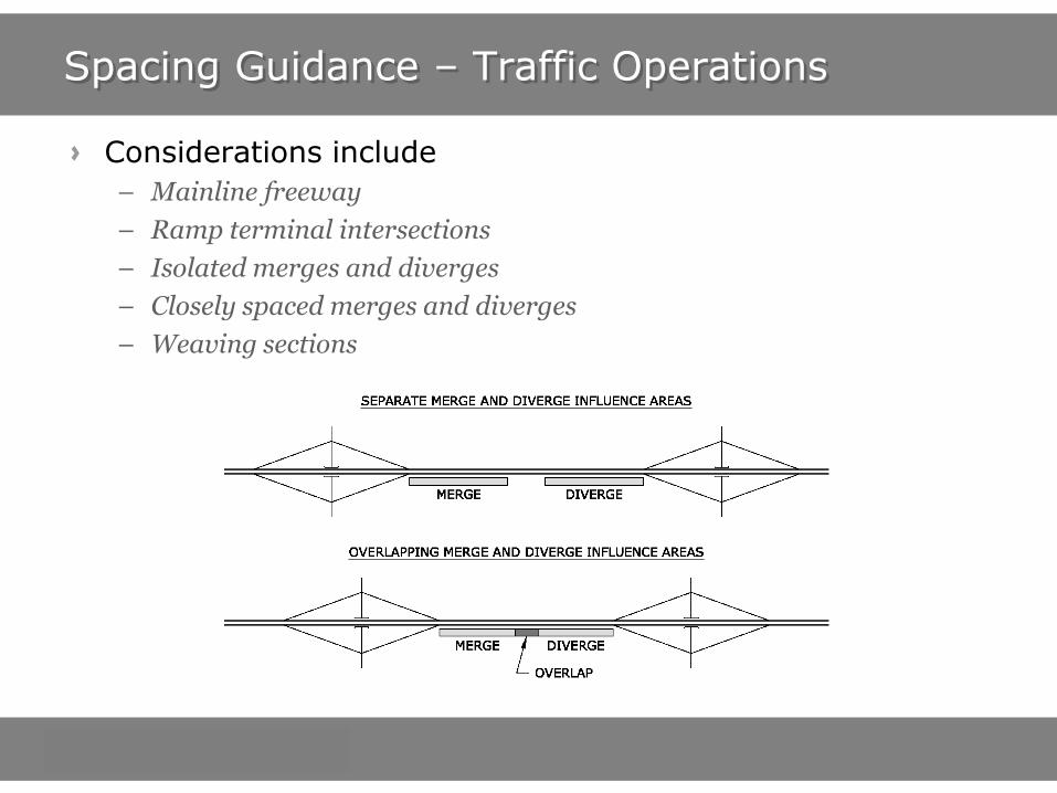
Spacing Guidance – Traffic Operations
Considerations include
– Mainline freeway
– Ramp terminal intersections
– Isolated merges and diverges
– Closely spaced merges and diverges
– Weaving sections

Operations Elements Affecting Spacing Needs
Queue storage needs
Terrain and grades
Ramp meters (entrance ramps)
Others
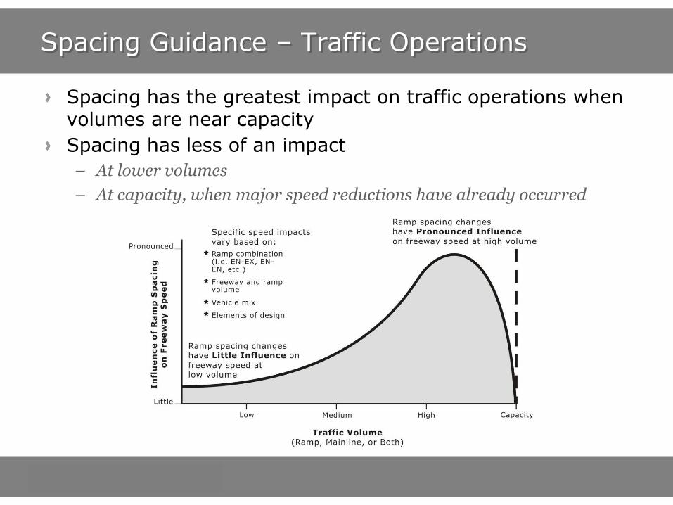
Spacing Guidance – Traffic Operations
Spacing has the greatest impact on traffic operations when volumes are near capacity
Spacing has less of an impact
– At lower volumes
– At capacity, when major speed reductions have already occurred

Spacing Guidance – Traffic Operations
Determine site-specific minimum values using:
– Planning-level tools
- ITE Ramp and Interchange Geometric Design Handbook
- Tables in HCM
- Findings of this project
– HCM Analysis
– Microsimulation
Many variables involved – “one size fits all” spacing values cannot be provided.

Spacing Guidance - Safety
Similar to traffic operations, many variables are involved
These guidelines provide crash trends for entry-exit and entry-entry ramp combinations
Graphs on following page illustrate trends based on our research

Spacing Guidance - Safety
1 Relative crash risk is measured by the percent difference in crashes, of all types and severities, at some ramp spacing value compared to a ramp spacing of 1600 feet (for EN-EX) or 1400 feet (for EN-EN)
Entry – Exit Entry - Entry

Spacing Guidance - Signing
Usually other elements require greater spacing than signing does
MUTCD requirements effectively dictate:
– 800 feet between exit ramps
– Maximum of 3 exit ramps per mile (4 if two ramps are part of the same interchange)
– Complex ramps/interchanges with greater signing needs will require greater exit-exit ramp spacing.

Webinar Overview
Project Introduction – Brian Ray
Guidelines – Brian Ray
Traffic Operations Work Plan – Pete Jenior
Case Studies: Traffic Operations Focus – Pete Jenior
Safety Work Plan – R.J. Porter
Case Studies: Safety and Signing Focus – R.J. Porter
Closing Remarks– Brian Ray
Questions - All

How does changing “L” affect average vehicle speed?
At what point does it “breakdown”?
Traffic Operations Work Plan (W.P.) - Goal
VF = Freeway volume
VR = Ramp volume

Traffic Operations – Literature Review
3 Highway Capacity Manual 2010 procedures relevant to ramp and interchange spacing
– Basic Freeway Segments
- Free-flow speed decreases as ramp density increases
– Freeway Weaving Segments
- Procedure applies only when auxiliary lane is present between entry ramp and exit ramp
- Outcomes highly dependent upon site-specific factors (lane configuration, traffic volume, etc)
- Procedure has changed dramatically in every major update of HCM (including 2010)
– Freeway Merge and Diverge Segments (formerly Ramp-Freeway Junctions)
- “Influence area” of ramp on freeway is 1500’, measured from painted gore
- Only 3-lane procedure sensitive to adjacent ramps or ramp spacing
No clear thresholds below which ramp or interchange spacings “don’t work”

Traffic Operations W.P. – Simulation Modeling
VISSIM
Calibrated with field data
Used to estimate the effect of ramp spacing on the mainline vehicle speed
Variables were systematically changed to determine their combined influence on average vehicle speed:
– Distance between the ramps ( 700’ & 1000’ to 2500’)
– Traffic volumes on each ramp and the freeway
Speeds measured at 5 locations in model, including both painted gores
Traffic Operations W.P. – EN-EX Findings
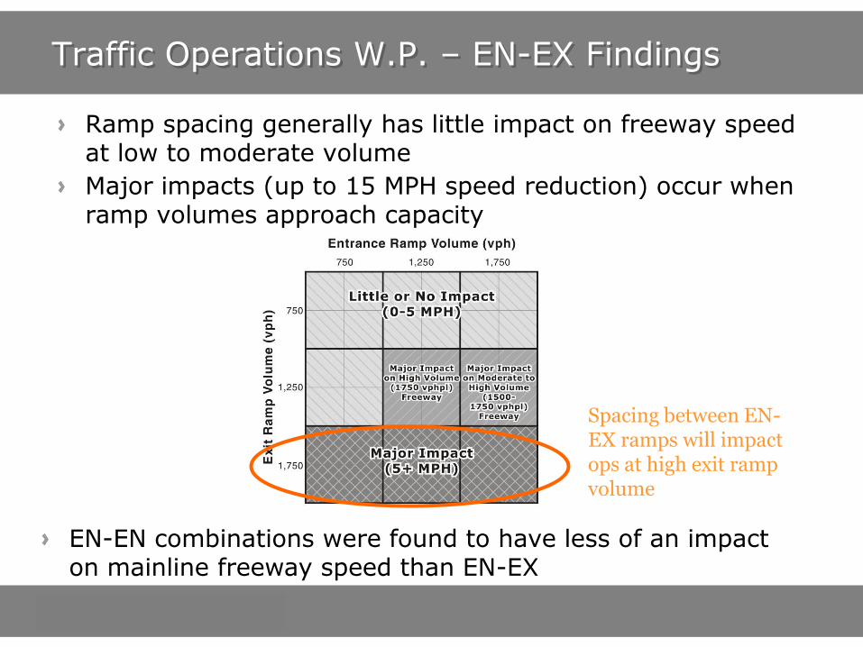
Ramp spacing generally has little impact on freeway speed at low to moderate volume
Major impacts (up to 15 MPH speed reduction) occur when ramp volumes approach capacity
EN-EN combinations were found to have less of an impact on mainline freeway speed than EN-EX
Spacing between EN-EX ramps will impact ops at high exit ramp volume
Traffic Operations W.P.– En-Ex Findings
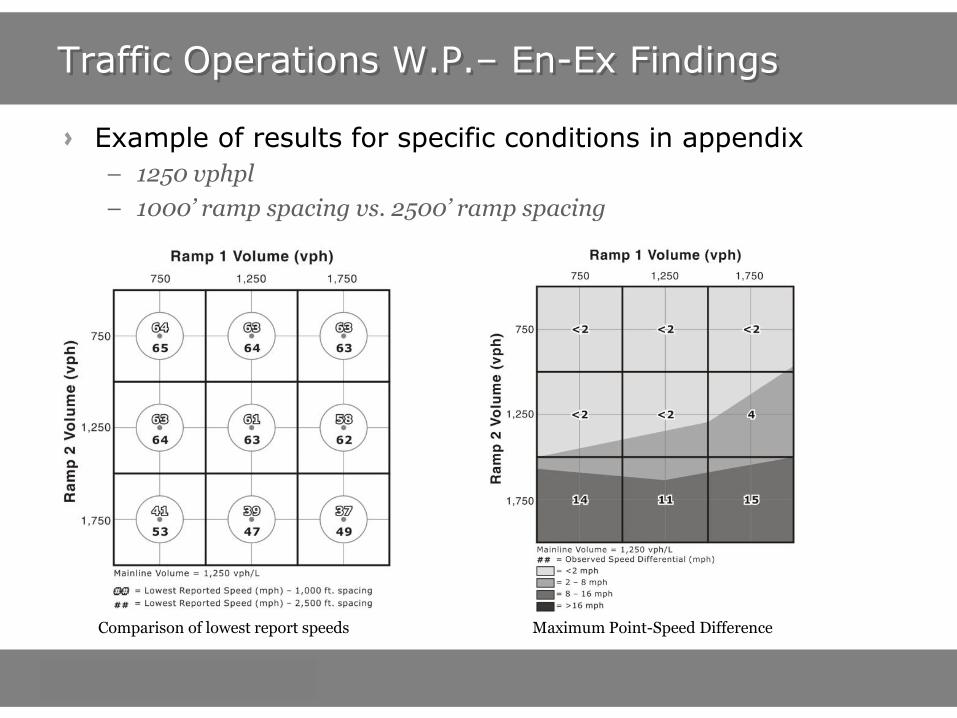
Example of results for specific conditions in appendix
– 1250 vphpl
– 1000’ ramp spacing vs. 2500’ ramp spacing
Comparison of lowest report speeds Maximum Point-Speed Difference

Traffic Operations W.P. – Aux Lane Findings
As project progressed, gap in research identified:
– Wealth of research on EN-EX operation with aux lane (i.e. weaving)
– Very little research on EN-EX operation without aux lane (i.e. what was studied in this project)
Additional VISSIM runs used to compare these two design options
VISSIM runs identified major (5+ MPH) benefits to adding an aux lane with moderate to high exit ramp volumes, regardless of ramp spacing

Traffic Operations W.P. – Aux Lane Findings
Benefit of adding an aux lane:
1000’ Ramp Spacing 2500’ Ramp Spacing
AUX Lane provides benefit with high exit ramp volume, regardless of ramp spacing

Case Study A
Source: NCHRP Report 687 Case Study #2

Case Study A
Background
– New diamond interchange on an Interstate highway
– Site has constrained geography between two half diamond interchanges
– Traffic volumes and characteristics
Case Study A
Recall the 4 considerations

Case Study A
Geometric considerations
– Determine interchange footprint
– Determine approximate length of ramps
– Ramp lengths governed by grade differences, and need to be lengthened
– EN-EX ramp spacing to west:
- ~3600’ eastbound
- ~4300’ westbound
– EX-EX and EN-EN ramp combinations to east

Case Study A
Traffic operations
– HCM ramp merge/diverge analysis performed for each ramp freeway junction. All meet LOS guideline for this area (LOS D)
– New interchange creates four closely-spaced ramp combinations
- Consider aux lanes between En-Ex combinations
Chart from Appendix B for 1,250 vphpl and 2500’ ramp spacing Benefit of aux lane expected to be minimal based on traffic operations

Case Study A
If aux lane used, will a weaving section (per HCM 2010) be created?
– Yes – conduct HCM weaving analysis
– Analysis found LOS D or better operation of weaving section
Case Study A
Safety and Signing
– Assessed – no issues
– An example of safety and signing evaluations is later in this presentation
Findings
– Interchange location appears to be feasible from a ramp and interchange spacing perspective
– All ramp-freeway junctions will meet the facility’s LOS Guideline
– Benefit of aux lane between En-Ex will be minimal
– If used, aux lane should be analyzed as a weaving section
– No safety or signing issues
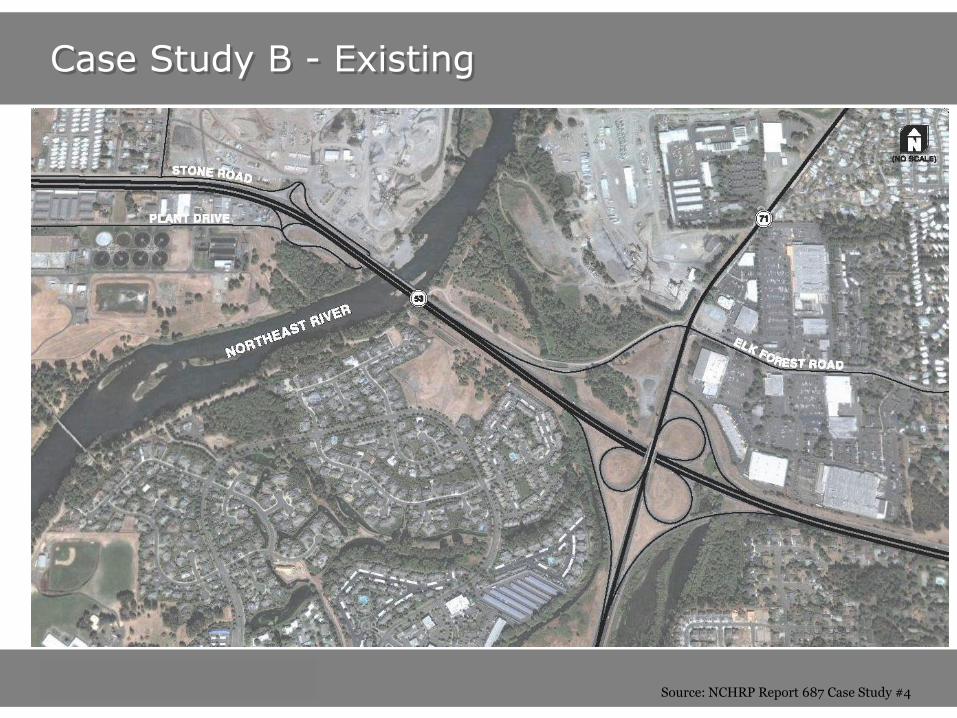
Case Study B - Existing
Source: NCHRP Report 687 Case Study #4

Case Study B
Background
– Modernization of a 1950-era freeway
– Evaluation of existing accesses for operational and safety issues
– Consider removing interchange, or reconstruction options
– Traffic volumes and characteristics
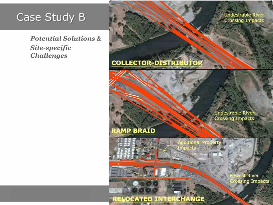
Case Study B
Potential Solutions &
Site-specific Challenges

Case Study B - Proposed
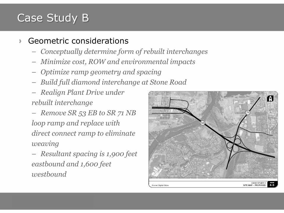
Case Study B
Geometric considerations
– Conceptually determine form of rebuilt interchanges
– Minimize cost, ROW and environmental impacts
– Optimize ramp geometry and spacing
– Build full diamond interchange at Stone Road
– Realign Plant Drive under
rebuilt interchange
– Remove SR 53 EB to SR 71 NB
loop ramp and replace with
direct connect ramp to eliminate
weaving
– Resultant spacing is 1,900 feet
eastbound and 1,600 feet
westbound

Case Study B
Traffic operations for SR 53 eastbound
– Weaving between loop ramps eliminated
– Initial operational analysis should assume no auxiliary lane due to potential costs and impacts with widening river bridge
– HCM merge/diverge analysis finds each merge/diverge in isolation operates acceptably (LOS D or better for this area)
– Ramp spacing:
- 1,900 ft proposed
- 2,200 ft existing
– Volumes:
- Freeway: 4,500 vph
- Entrance: 300 vph
- Exit: 1,200 vph
– Assess spacing impacts (next slide)

Case Study B
Planning-level spacing assessment for 3-lane freeway

Case Study B
Safety (not focus of this section of webinar)
– Ramps slightly closer together
– Weaving segment removed
– Hook ramps removed
Signing (not focus of this section of webinar)
– Current westbound signing is adequate
– Eastbound signing is simplified by removing loop ramp
- Only one sign panel needed at the locations that currently have two
- Each of the signs will have one less message unit
– Eastbound signing before rebuilt interchange is ok
– All westbound signs adhere to MUTCD standards
– No signing issues are anticipated

Case Study B
Findings
– Rebuilding interchange appears feasible at conceptual development stage
– Operations, safety and signing will improve or meet standards
– Reevaluation will needed as design is more fully developed

Webinar Overview
Project Introduction – Brian Ray
Guidelines – Brian Ray
Traffic Operations Work Plan – Pete Jenior
Case Studies: Traffic Operations Focus – Pete Jenior
Safety Work Plan – R.J. Porter
Case Studies: Safety and Signing Focus – R.J. Porter
Closing Remarks– Brian Ray
Questions - All
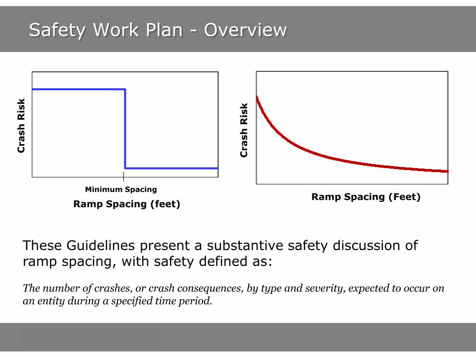
Safety Work Plan - Overview
0 1600 3200
Crash
Ris
k
Ramp Spacing (feet)
Minimum Spacing
Crash
Ris
k
Ramp Spacing (Feet)
These Guidelines present a substantive safety discussion of ramp spacing, with safety defined as: The number of crashes, or crash consequences, by type and severity, expected to occur on an entity during a specified time period.

Safety – Literature Review
A number of previous studies on this topic have explored the effect of ramp and interchange presence on safety, without considering a spacing effect
Others reported safety effects of a ramp or interchange count or density on a freeway segment
Only three studies took a direct look at the relationship between interchange or ramp spacing and safety
Conclusions prior to this project were that “Decreasing interchange spacing appears to increase crashes…the magnitude of the crash effect is not certain at this time” (Highway Safety Manual, 1st Edition)
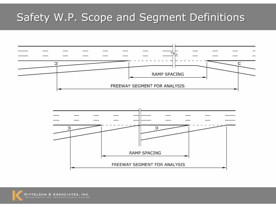
Safety W.P. Scope and Segment Definitions
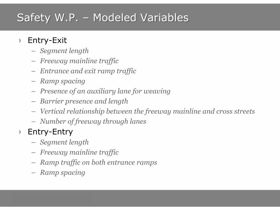
Safety W.P. – Modeled Variables
Entry-Exit
– Segment length
– Freeway mainline traffic
– Entrance and exit ramp traffic
– Ramp spacing
– Presence of an auxiliary lane for weaving
– Barrier presence and length
– Vertical relationship between the freeway mainline and cross streets
– Number of freeway through lanes
Entry-Entry
– Segment length
– Freeway mainline traffic
– Ramp traffic on both entrance ramps
– Ramp spacing

Spacing Guidance - Safety
Total Crashes at Entry-Exit Ramp Combination
Variable definitions:
AuxLnS
ADTADTDADTLTOTAL EXEN 23.0450
exp107.902.018.012.10.16
L = segment length (in miles) defined from the physical gore of the entrance ramp to the physical gore of the exit ramp; S = ramp spacing (in feet) defined from the painted entrance gore to the painted exit gore; DADT = the average daily traffic (in vehicles per day) on the freeway mainline upstream of the entrance gore in the analysis direction; ADTEN = the average daily entering traffic (in vehicles per day); ADTEX = the average daily exiting traffic (in vehicles per day); AuxLn = a variable indicated whether there is a continuous auxiliary lane between the entrance ramp and exit ramp provided for weaving (1 = auxiliary lane present; 0 = auxiliary lane not present); and TOTAL = number of crashes (of all types and severities) expected to occur between the physical entrance gore and physical exit gore on the freeway mainline

Spacing Guidance - Safety
Total Crashes at Entry-Entry Ramp Combination
Variable definitions:
SADTADTDADTLTOTAL ENEN
420exp100.5
09.0
2
34.0
1
81.00.15
L = segment length (in miles) defined from the physical gore of the first (upstream) entrance ramp to the end of the acceleration lane taper of the second (downstream) entrance ramp; S = ramp spacing (in feet) defined from the painted tip of the first entrance ramp to the painted tip of the second entrance ramp; DADT = the average daily traffic (in vehicles per day) on the freeway mainline upstream of the first entrance gore in the analysis direction; ADTEN-1 = the average daily entering traffic (in vehicles per day) from the first entrance ramp; ADTEN-2 = the average daily entering traffic (in vehicles per day) from the second entrance ramp; and TOTAL = number of crashes (of all types and severities) (crashes per year) expected to occur between the physical gore of the first

Spacing Guidance - Safety
1 Relative crash risk is measured by the percent difference in crashes, of all types and severities, at some ramp spacing value compared to a ramp spacing of 1600 feet (for EN-EX) or 1400 feet (for EN-EN)
Entry – Exit Entry - Entry

Spacing Guidance - Safety
Example: Planners must choose between 1600’ and 1200’ EN-EX ramp spacing – will there be a safety impact?
10% more crashes with 1200’ spacing

Spacing Guidance - Safety
Example: Planners must choose between 2600’ and 3000’ EN-EX ramp spacing – will there be a safety impact?
No

Crash Type and Severity
0%
10%
20%
30%
40%
50%
60%
70%
80%
90%
100%
600 1000 1400 1800 2200 2600 3000
Percen
t o
f To
tal C
rash
es
Ramp Spacing (feet)
Fatal plus injury
Multiple vehicle crashes

Safety W.P. – EN-EX Model Aux Lane Effects
Like operations research, safety research found a benefit of having an aux lane between closely spaced entry ramp and exit ramp
The presence of an auxiliary lane corresponded to approximately 20% fewer expected crashes for any given ramp spacing and projected level of traffic volumes.
This overall reduction in crashes is due to reduction in multiple vehicle collisions.
The presence of an auxiliary lane has no effect on single vehicle collisions. The presence of an auxiliary lane was also found to have an equal reduction in injury and non-injury crashes.

Spacing Guidance - Safety
Example: comparing 2,000 foot and 1,400 foot spacing, the larger expected number of crashes for the 1,400 foot spacing is expected to be offset if an auxiliary lane is provided

Spacing Guidance - Safety
A comprehensive ramp spacing safety assessment should consider:
Safety impacts on the freeway mainline (addressed in this section);
Safety associated with speed-change lane presence and design;
Safety along the ramp proper;
Safety at ramp terminal intersections; and
Safety on surrounding highways and streets (capabilities that intertwine travel demand modeling and safety are somewhat limited).

Signing – Literature Review
MUTCD specifies limits on the amount of information that can be presented to freeway drivers
– Limits effectively set a maximum exit ramp density
– Other factors such as geometric design usually require exit ramps to be far enough apart that signing does not influence spacing
ITE Freeway and Interchange Geometric Design Handbook. 2005
MUTCD limit

Case Study C
Source: NCHRP Report 687 Case Study #3

Case Study C
Background
– New interchange a mile from adjacent interchanges in both directions
– Single-point diamond is being considered, with auxiliary lanes to the north and south
– High traffic volumes present operational and safety concerns

Case Study C
Geometric considerations
– Single-point diamond interchange proposed
– Exit ramps vary from 1,600 – 2,000 feet in length
– Entrance ramps vary from 1,700 – 2,000 feet in length
– Maintain adequate deceleration distance on exit ramps
– Ramp meters will require longer entrance ramp to avoid queue spillback
– Results in four closely spaced ramp combinations (< 2,000 feet)
Traffic operations
– Interchange found feasible from a traffic operations perspective
– See NCHRP Report for details
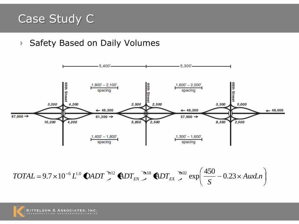
Case Study C
Safety Based on Daily Volumes
AuxLnS
ADTADTDADTLTOTAL EXEN 23.0450
exp107.902.018.012.10.16

Case Study C
0%
10%
20%
30%
40%
50%
60%
70%
80%
90%
100%
600 1000 1400 1800 2200 2600 3000
Percen
t o
f To
tal C
rash
es
Ramp Spacing (feet)
Fatal plus injury crashes
Multiple vehicle crashes
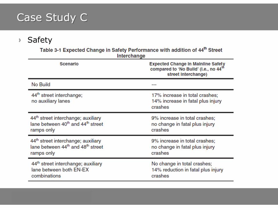
Case Study C
Safety
Case Study C
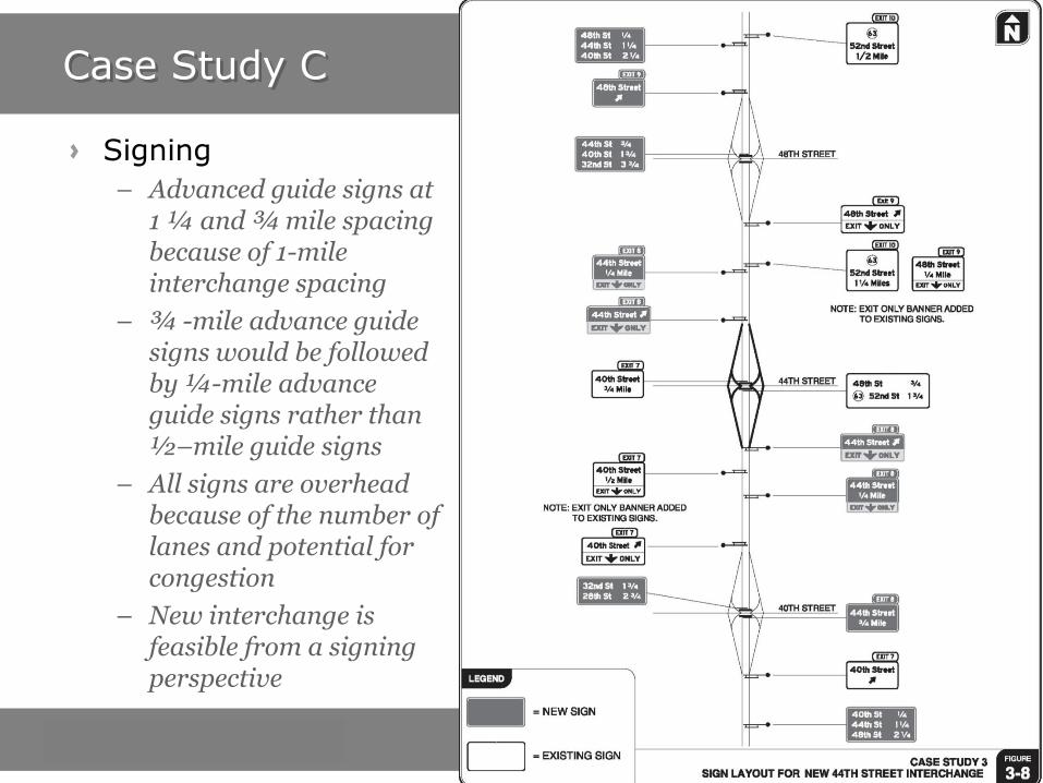
Signing
– Advanced guide signs at 1 ¼ and ¾ mile spacing because of 1-mile interchange spacing
– ¾ -mile advance guide signs would be followed by ¼-mile advance guide signs rather than ½–mile guide signs
– All signs are overhead because of the number of lanes and potential for congestion
– New interchange is feasible from a signing perspective

Case Study C
Findings
– New interchange does not have any fatal flaws
– Weaving areas will be created
– Auxiliary lanes are needed
– HCM analysis necessary to see if segments meet LOS E operating guideline
– If auxiliary lanes are provided, number of crashes would not be expected to increase
– Signing is feasible with proposed interchange type

Webinar Overview
Project Introduction – Brian Ray
Guidelines – Brian Ray
Traffic Operations Work Plan – Pete Jenior
Case Studies: Traffic Operations Focus – Pete Jenior
Safety Work Plan – R.J. Porter
Case Studies: Traffic Operations and Signing Focus – R.J. Porter
Closing Remarks– Brian Ray
Questions - All

Guidelines - Outcomes
Clear definition of spacing terms
– Focus on ramp spacing
– Deemphasize interchange spacing
Systematic approach that considers
– Geometric design
– Traffic operations
– Safety
– Signing
Performance-based Transportation
– Avoid “one size fits all” spacing values
– Customize spacing recommendations based on factors that affect ramp and interchange context

Questions