NCHRP Project 25-34 / Report 791 “Supplemental … TRB14.pdfNCHRP Project 25-34 / Report 791...
23
NCHRP Project 25-34 / Report 791 “Supplemental Guidance on the Application of FHWA’s Traffic Noise Model (TNM)” Overview and Results for Topography, Ground Zones, Tree Zones and Atmospherics Christopher Menge Harris Miller Miller & Hanson Inc. Transportation Research Board ADC40 Summer Meeting Portsmouth, NH July 21, 2014
-
Upload
truongthuy -
Category
Documents
-
view
216 -
download
2
Transcript of NCHRP Project 25-34 / Report 791 “Supplemental … TRB14.pdfNCHRP Project 25-34 / Report 791...

NCHRP Project 25-34 / Report 791“Supplemental Guidance on the Application of
FHWA’s Traffic Noise Model (TNM)”
Overview and Results for Topography, Ground Zones, Tree Zones and Atmospherics
Christopher MengeHarris Miller Miller & Hanson Inc.Transportation Research Board
ADC40 Summer MeetingPortsmouth, NH
July 21, 2014

Objectives of Research Project 25-34
Supplement existing guidance for using TNM by identifying Best Practices to accurately, consistently, and efficiently model 9 special highway noise scenarios
Determine the sensitivity and accuracy of the methods to model 5 other special scenarios
Synthesize the state of practice for analyzing the effects of (1) wind direction and (2) temperature on sound propagation

Research Topics of NCHRP Project 25-34
1. Structure Reflected Noise and Expansion Joint Noise
2. Signalized Interchanges, Intersections and Roundabouts
3. Area Sources4. Median Barriers5. Multi-lane Highways
6. Building Rows7. Topography8. Ground Zones9. Tree Zones10. Wind and
Temperature Gradients
11. Parallel Barriers12. Tunnel Openings

The 7-Step Process
1. Determine existence of useful information
2. Compile modeling techniques & validation data
3. Identify candidate modeling techniques
4. Prepare interim technical report & receive comments
5. Process existing validation data and/or collect additional data
6. Test and evaluate modeling techniques and identify Best Practices
7. Prepare final technical report

Topography
Sensitivity analysis performed for several TNM objects and topography-related concerns: Outside edge of pavement – horizontal precision Required Terrain Lines along elevated roadways Minimum Terrain Line spacing Terrain Lines: vertical precision Barrier tops: vertical precision Flat-top berms

Topography Best Practices
Outside edge of pavement – horizontal precision “Shoulder” roadway is recommended, carefully
following edge of pavement
Required Terrain Lines along elevated roadways Roads on fill - located at toe of slope Roads on structure: located at ground level just off
edge of structure

Topography Best Practices
Minimum Terrain Line spacing Never closer spacing than 4 feet, to avoid
computational errors Do not duplicate triangular regions produced by
digital terrain models
Terrain Lines: vertical precision Keep precision with plus/minus one foot

Topography Best Practices
Barrier tops: vertical precision Sound levels can be very sensitive to barrier top
elevation In final barrier-design studies
– Carefully specify barrier top elevation for accurate future Leqs
– Also, carefully determine future ground elevation for accurate insertion loss calculations

Topography Best Practices
Flat-top berms For greatest accuracy: “Round-off” the edges of flat-
top bermsW = flat-top width
Ground Zones
Sensitivity analysis performed and guidance given for aspects of Ground Zones: Size and location of Ground Zones Expanded list of ground types Bodies of water

Ground Zones Best Practices
General size: Not needed for small patches (e.g. sidewalks and
driveways) 20% of source-to-receiver distance for > 1 dBA
Coordinate precision: High precision not needed in horizontal plane 30-foot change in ground zone width may cause 1 dB
change
Location: Needed near middle of propagation path where ground
zone covers >10 to 20% of distance along path
Ground Zones Best Practices
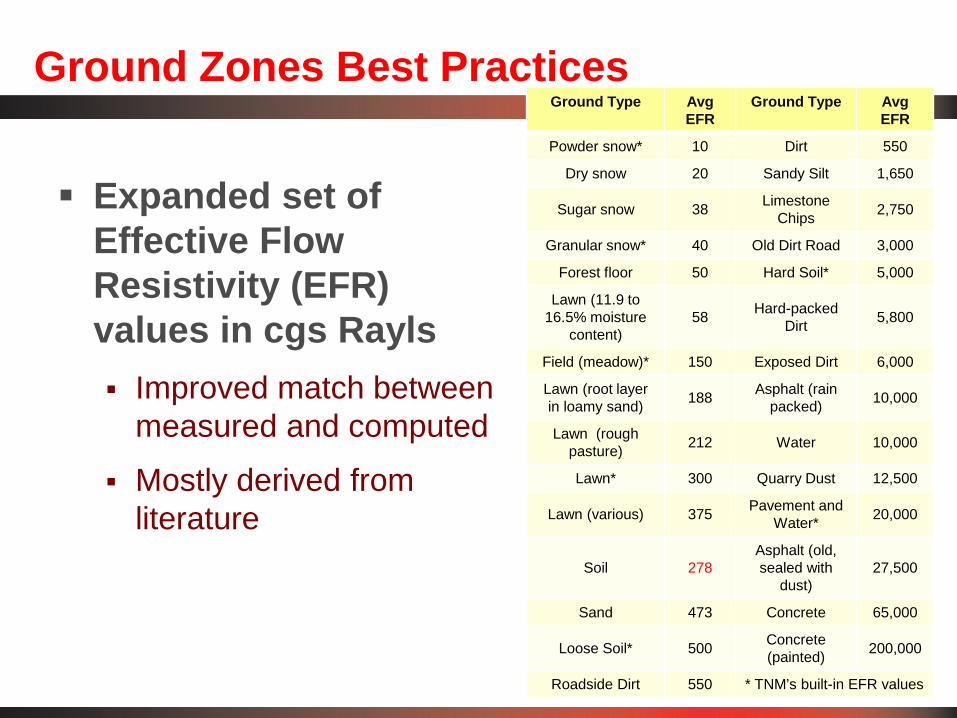
Expanded set of Effective Flow Resistivity (EFR) values in cgs Rayls Improved match between
measured and computed
Mostly derived from literature
Ground Type AvgEFR
Ground Type AvgEFR
Powder snow* 10 Dirt 550
Dry snow 20 Sandy Silt 1,650
Sugar snow 38 Limestone Chips 2,750
Granular snow* 40 Old Dirt Road 3,000
Forest floor 50 Hard Soil* 5,000
Lawn (11.9 to 16.5% moisture
content)58 Hard-packed
Dirt 5,800
Field (meadow)* 150 Exposed Dirt 6,000
Lawn (root layer in loamy sand) 188 Asphalt (rain
packed) 10,000
Lawn (rough pasture) 212 Water 10,000
Lawn* 300 Quarry Dust 12,500
Lawn (various) 375 Pavement and Water* 20,000
Soil 278Asphalt (old, sealed with
dust)27,500
Sand 473 Concrete 65,000
Loose Soil* 500 Concrete(painted) 200,000
Roadside Dirt 550 * TNM’s built-in EFR values

Ground Zones Best Practices
Use of Expanded EFR values in TNM Designate “custom” ground zones with appropriate EFR
value Default ground type from TNM’s pull-down list, overlaid
with zones of custom EFR values
Bodies of water Include if water is at middle of propagation path and is
more than 10 to 20% of the source-to-receiver distance Include terrain lines and top and bottom of bank
Distances beyond 500 feet – be aware: Soft ground: TNM under-predicts Hard ground: TNM over-predicts

Tree Zones
Consider modeling narrow tree zones (parallel to roadway) that are 50 to 100 feet deep
– Reduce needed barrier length & cost
No overlaid ground zone needed with tree zones
Consider visibility through tree zone using Fang & Linn equation
Sensitivity analysis performed and guidance given for aspects of Tree Zones:
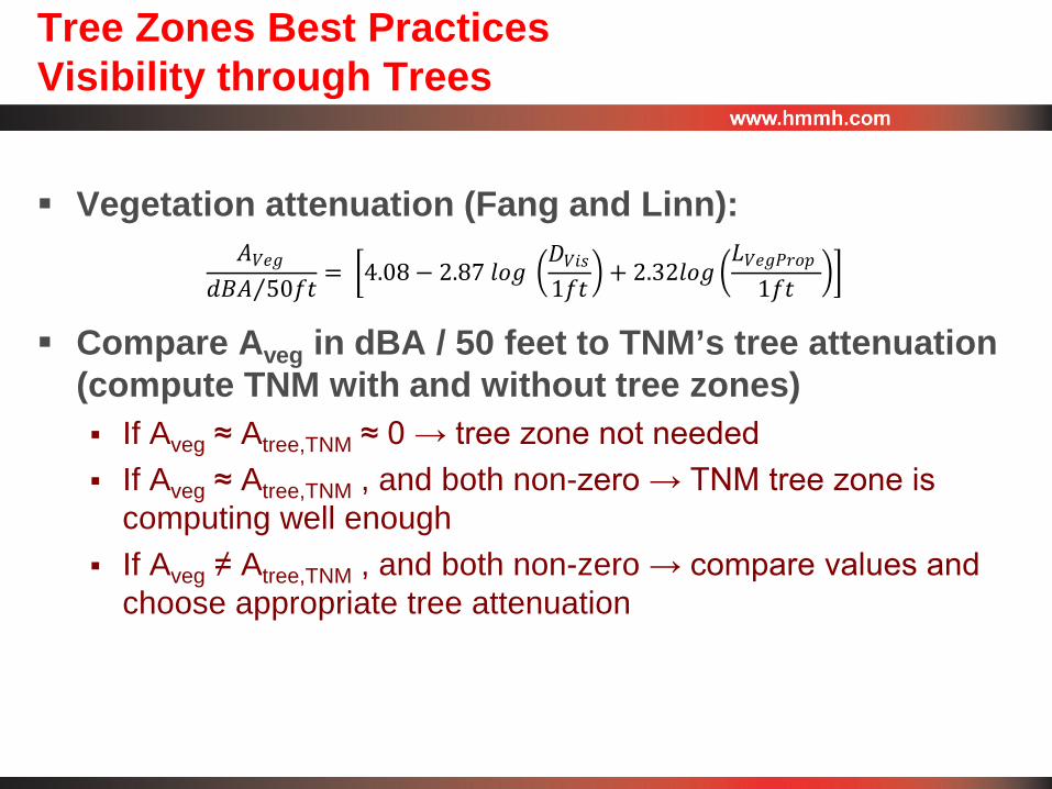
Tree Zones Best PracticesVisibility through Trees
Vegetation attenuation (Fang and Linn):
Compare Aveg in dBA / 50 feet to TNM’s tree attenuation (compute TNM with and without tree zones) If Aveg ≈ Atree,TNM ≈ 0 → tree zone not needed If Aveg ≈ Atree,TNM , and both non-zero → TNM tree zone is
computing well enough If Aveg ≠ Atree,TNM , and both non-zero → compare values and
choose appropriate tree attenuation
𝐴𝐴𝑉𝑉𝑉𝑉𝑉𝑉𝑑𝑑𝑑𝑑𝐴𝐴 50𝑓𝑓𝑓𝑓⁄ = �4.08− 2.87 𝑙𝑙𝑙𝑙𝑉𝑉 �
𝐷𝐷𝑉𝑉𝑉𝑉𝑉𝑉1𝑓𝑓𝑓𝑓
� + 2.32𝑙𝑙𝑙𝑙𝑉𝑉 �𝐿𝐿𝑉𝑉𝑉𝑉𝑉𝑉𝑉𝑉𝑉𝑉𝑙𝑙𝑉𝑉
1𝑓𝑓𝑓𝑓��
Wind and Temperature Gradients
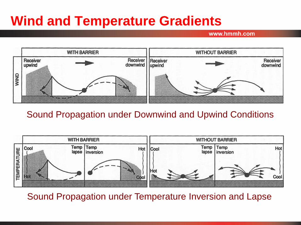
Sound Propagation under Downwind and Upwind Conditions
Sound Propagation under Temperature Inversion and Lapse

Wind and Temperature Gradients
Extensive literature review Very few quantitative studies of atmospheric effects on
highway noise Among those, limited data universally applicable
Nord2000 propagation model incorporates wind and temperature gradient effects Atmospheric effects validated through measurements

Wind and Temperature Gradients
SoundPLAN® prediction program incorporates Nord2000 and TNM implementations
Nord2000 and TNM show comparable results under calm, neutral atmospheric conditions
Nord2000 run under a wide range of scenarios to determine atmospheric effects

Wind and Temperature GradientsVariables Run with Nord2000
Typical 4-lane highway geometry Autos/Truck mix and Autos only Receiver distances: 50, 100, 200, 400, 800, 1600 ft Receiver heights: 5 ft and 15 ft Soft ground and hard ground No barrier and 17-ft high barrier
Upwind and downwind: Calm, 2.5 m/s (5.6 mph), 5 m/s (11.2 mph)
Temperature inversion: +0.1 ºC/m, +0.5 ºC/m Temperature lapse: -0.1 ºC/m, -0.3 ºC/m

Wind and Temperature GradientsExample Results Table

Wind and Temperature GradientsExample Results Graph
-30
-20
-10
0
10
20
10 100 1000
Soun
d Le
vel D
iffer
ence
, Tem
p. C
ondi
tion
-Cal
m (d
B)
Distance (feet)
Temp. Effects: 5-ft Rec; Autos & Trucks; No Barrier; Soft Grnd.
calm +0.5 C/m +0.1 C/m -0.1 C/m -0.3 C/m

Team Members & Acknowledgements
Topography, Ground Zones and Tree Zones - Grant Anderson
Wind and Temperature Gradients - HMMH Christopher Menge – principal investigator Bradley Nicholas – literature review, interim report Timothy Johnson – SoundPLAN/TNM modeling, final report Rhea Gundry, HMMH – SoundPLAN modeling

www.hmmh.com