NC1 Contactor, 9~95A 1. General - ingramproducts.com Contactor, 9~95A 2. ... 1. General 1.1...
12
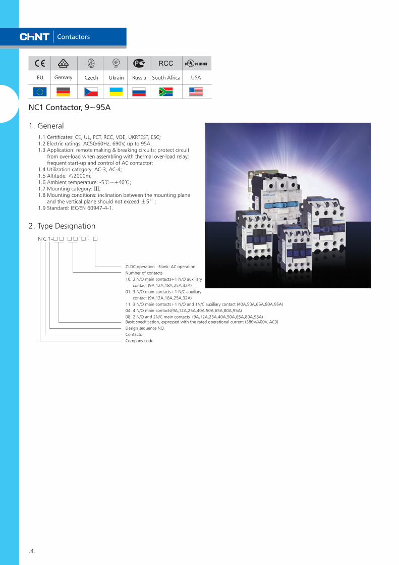
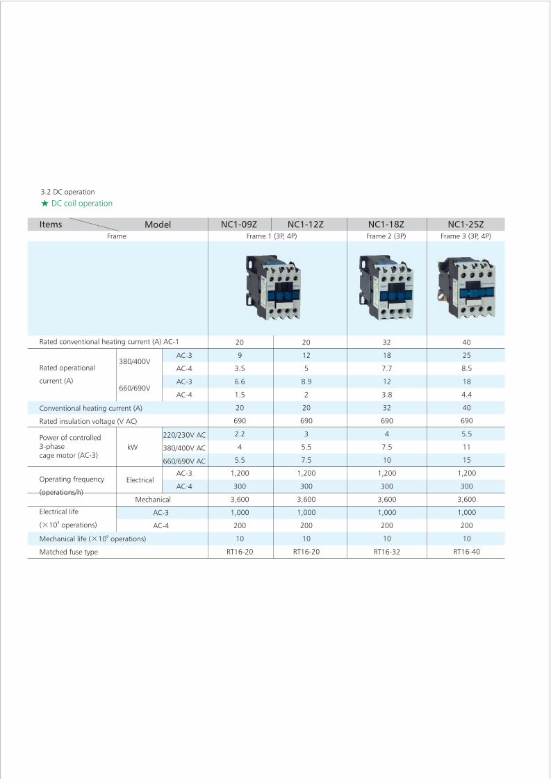
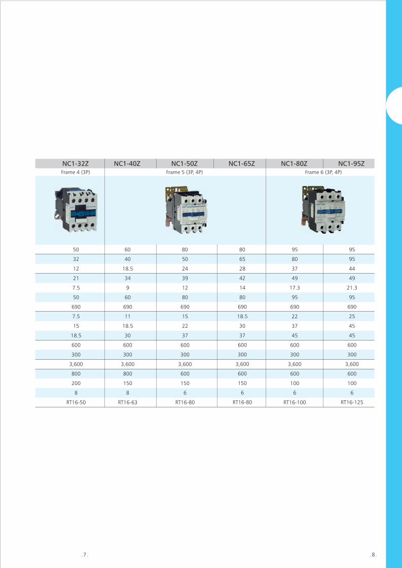
Contactors .4. 1. General 1.1 Certificates: CE, UL, PCT, RCC, VDE, UKRTEST, ESC; 1.2 Electric ratings: AC50/60Hz, 690V, up to 95A; 1.3 Application: remote making & breaking circuits; protect circuit from over-load when assembling with thermal over-load relay; frequent start-up and control of AC contactor; 1.4 Utilization category: AC-3, AC-4; 1.5 Altitude: ≤2000m; 1.6 Ambient temperature: -5℃~+40℃; 1.7 Mounting category: Ⅲ; 1.8 Mounting conditions: inclination between the mounting plane and the vertical plane should not exceed ±5°; 1.9 Standard: IEC/EN 60947-4-1. NC1 Contactor, 9~95A 2. Type Designation N C 1-□□ □□ □ - □ Z: DC operation Blank: AC operation Number of contacts 10: 3 N/O main contacts+1 N/O auxiliary contact (9A,12A,18A,25A,32A) 01: 3 N/O main contacts+1 N/C auxiliary contact (9A,12A,18A,25A,32A) 11: 3 N/O main contacts+1 N/O and 1N/C auxiliary contact (40A,50A,65A,80A,95A) 04: 4 N/O main contacts(9A,12A,25A,40A,50A,65A,80A,95A) 08: 2 N/O and 2N/C main contacts (9A,12A,25A,40A,50A,65A,80A,95A) Basic specification, expressed with the rated operational current (380V/400V, AC3) Design sequence NO. Contactor Company code Ukrain Russia EU Germany Czech USA C US LISTED South Africa
-
Upload
dangkhuong -
Category
Documents
-
view
234 -
download
3
Transcript of NC1 Contactor, 9~95A 1. General - ingramproducts.com Contactor, 9~95A 2. ... 1. General 1.1...
Contactors
.4.
1. General
1.1 Certificates: CE, UL, PCT, RCC, VDE, UKRTEST, ESC;1.2 Electric ratings: AC50/60Hz, 690V, up to 95A;1.3 Application: remote making & breaking circuits; protect circuit from over-load when assembling with thermal over-load relay; frequent start-up and control of AC contactor;1.4 Utilization category: AC-3, AC-4;1.5 Altitude: ≤2000m;1.6 Ambient temperature: -5℃~+40℃;1.7 Mounting category: Ⅲ;1.8 Mounting conditions: inclination between the mounting plane and the vertical plane should not exceed ±5°;1.9 Standard: IEC/EN 60947-4-1.
NC1 Contactor, 9~95A
2. Type Designation
N C 1-□□ □□ □ - □
Z: DC operation Blank: AC operation
Number of contacts
10: 3 N/O main contacts+1 N/O auxiliary
contact (9A,12A,18A,25A,32A)
01: 3 N/O main contacts+1 N/C auxiliary
contact (9A,12A,18A,25A,32A)
11: 3 N/O main contacts+1 N/O and 1N/C auxiliary contact (40A,50A,65A,80A,95A)
04: 4 N/O main contacts(9A,12A,25A,40A,50A,65A,80A,95A)
08: 2 N/O and 2N/C main contacts (9A,12A,25A,40A,50A,65A,80A,95A) Basic specification, expressed with the rated operational current (380V/400V, AC3)
Design sequence NO.
Contactor
Company code
Ukrain Russia EU Germany Czech USA
RC US LISTED
South Africa
.14.
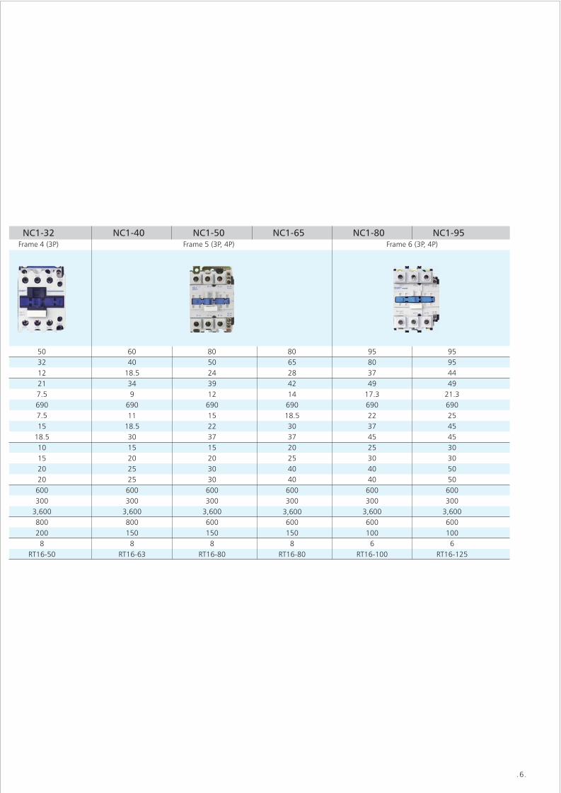
NC1-40
NC1-50
NC1-65
NC1-80
NC1-95 NRE8-100
65
100
30~65
50~100
RT36-160 (NT00-160)
RT36-200 (NT1-200)
RT36-10 (NT00-10)
RT36-16 (NT00-16)
RT36-20 (NT00-20)
RT36-40 (NT00-40)
RT36-80 (NT00-80)
2~4
4~8
5~10
10~20
20~40
4
8
10
20
40NRE8-40
NC1-40
Model of contactor
Assembled thermal current (A)
over-load relaycurrent (A)Model
Rated
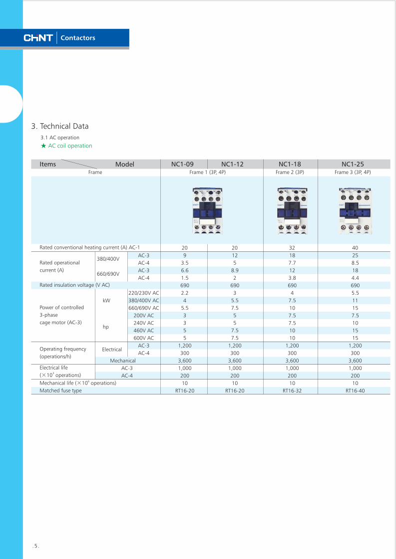
NC1-09
NC1-12
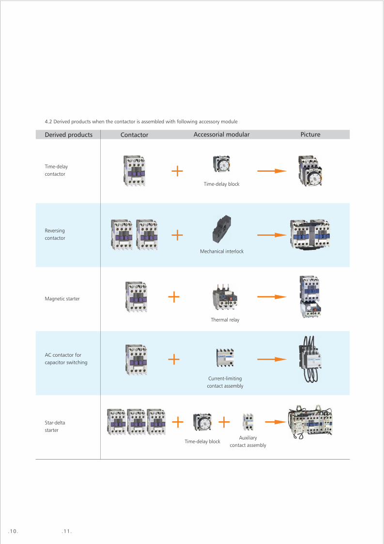
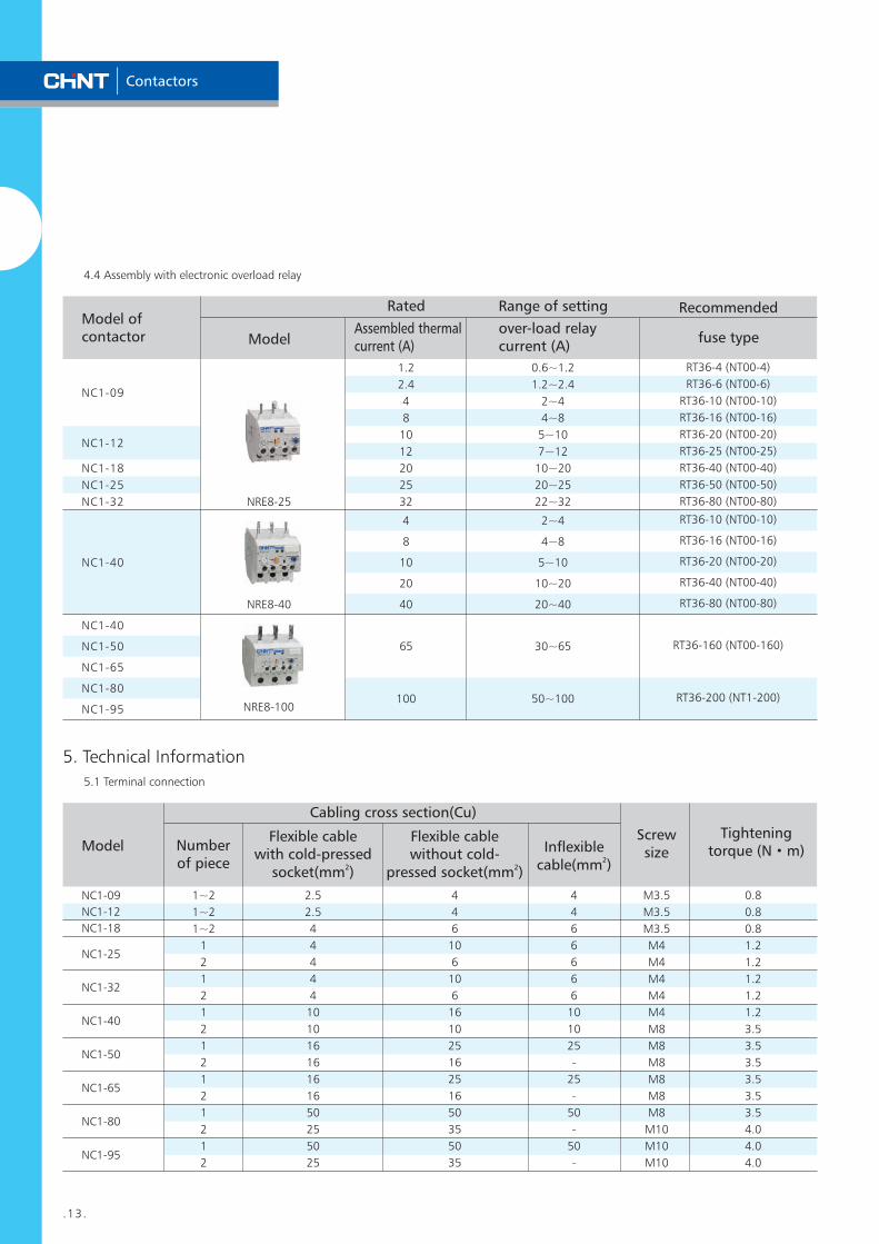
4.4 Assembly with electronic overload relay
Range of setting Recommended
fuse type
RT36-4 (NT00-4)
RT36-6 (NT00-6)
RT36-10 (NT00-10)
RT36-16 (NT00-16)
RT36-20 (NT00-20)
RT36-25 (NT00-25)
RT36-40 (NT00-40)
RT36-50 (NT00-50)
RT36-80 (NT00-80)
0.6~1.2
1.2~2.4
2~4
4~8
5~10
7~12
10~20
20~25
22~32
1.2
2.4
4
8
10
12
20
25
32
NC1-18
NC1-25
NC1-32 NRE8-25
5. Technical Information
5.1 Terminal connection
Model
Cabling cross section(Cu)
Number of piece
Flexible cable with cold-pressed
2socket(mm )
Inflexible2cable(mm )
Screw size
Tightening torque (N·m)
1~2
1~2
1~2
1
2
1
2
1
2
1
2
1
2
1
2
1
2
2.5
2.5
4
4
4
4
4
10
10
16
16
16
16
50
25
50
25
4
4
6
10
6
10
6
16
10
25
16
25
16
50
35
50
35
4
4
6
6
6
6
6
10
10
25
-
25
-
50
-
50
-
M3.5
M3.5
M3.5
M4
M4
M4
M4
M4
M8
M8
M8
M8
M8
M8
M10
M10
M10
0.8
0.8
0.8
1.2
1.2
1.2
1.2
1.2
3.5
3.5
3.5
3.5
3.5
3.5
4.0
4.0
4.0
NC1-09
NC1-12
NC1-18
NC1-25
NC1-32
NC1-40
NC1-50
NC1-65
NC1-80
NC1-95
Flexible cable without cold-
2pressed socket(mm )
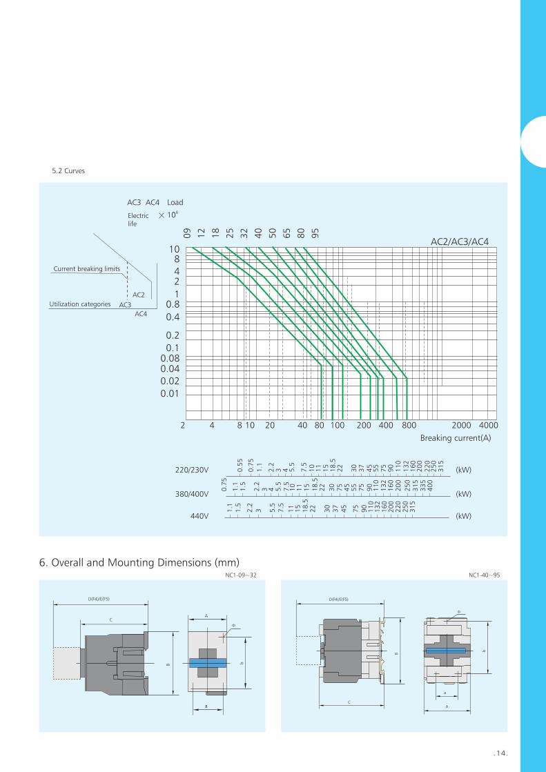
5.2 Curves
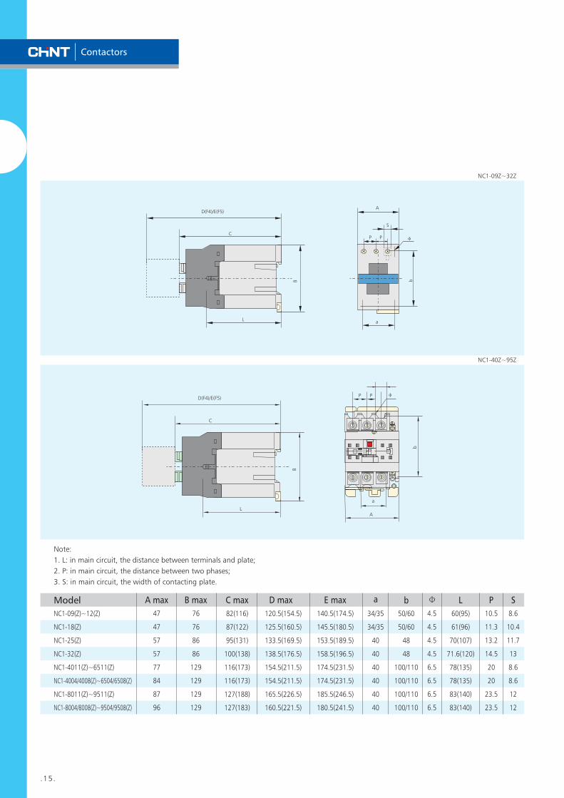
6. Overall and Mounting Dimensions (mm) NC1-09~32 NC1-40~95
A
b
a
Φ
D(F4)/E(F5)
C
B
D(F4)/E(F5)
C
B
b
a
A
Φ
Load
Electriclife
610
AC3 AC4
Current breaking limits
Utilization categories AC3
AC4
AC2
Breaking current(A)
09
12
18
25
32
40
50
65
80
95
10842
10.8
0.4
0.2
0.10.080.04
0.02
0.01
AC2/AC3/AC4
2 4 8 10 20 40 80 100 200 400 800 2000 4000
220/230V
380/400V
440V
(kW)
(kW)
(kW)
1.1
1.5
2.2
3 5.5
7.5
11
15
18
.52
2
30
37
45
75
90
11
01
32
16
02
00
22
02
50
31
5
0.7
5
1.1
1.5
2.2
3 4 5.5
7.5
10
11
15
18
.522
30
75
45
55
75
90
11
013
216
020
0
25
031
533
540
0
0.5
5
0.7
5
1.1
2.2
3 4 5.5
7.5
10
11
15
18
.52
2
30
37
45
55
75
90
11
01
32
16
02
00
22
02
50
31
5
Contactors
.13.
.14.
NC1-40
NC1-50
NC1-65
NC1-80
NC1-95 NRE8-100
65
100
30~65
50~100
RT36-160 (NT00-160)
RT36-200 (NT1-200)
RT36-10 (NT00-10)
RT36-16 (NT00-16)
RT36-20 (NT00-20)
RT36-40 (NT00-40)
RT36-80 (NT00-80)
2~4
4~8
5~10
10~20
20~40
4
8
10
20
40NRE8-40
NC1-40
Model of contactor
Assembled thermal current (A)
over-load relaycurrent (A)Model
Rated
NC1-09
NC1-12
4.4 Assembly with electronic overload relay
Range of setting Recommended
fuse type
RT36-4 (NT00-4)
RT36-6 (NT00-6)
RT36-10 (NT00-10)
RT36-16 (NT00-16)
RT36-20 (NT00-20)
RT36-25 (NT00-25)
RT36-40 (NT00-40)
RT36-50 (NT00-50)
RT36-80 (NT00-80)
0.6~1.2
1.2~2.4
2~4
4~8
5~10
7~12
10~20
20~25
22~32
1.2
2.4
4
8
10
12
20
25
32
NC1-18
NC1-25
NC1-32 NRE8-25
5. Technical Information
5.1 Terminal connection
Model
Cabling cross section(Cu)
Number of piece
Flexible cable with cold-pressed
2socket(mm )
Inflexible2cable(mm )
Screw size
Tightening torque (N·m)
1~2
1~2
1~2
1
2
1
2
1
2
1
2
1
2
1
2
1
2
2.5
2.5
4
4
4
4
4
10
10
16
16
16
16
50
25
50
25
4
4
6
10
6
10
6
16
10
25
16
25
16
50
35
50
35
4
4
6
6
6
6
6
10
10
25
-
25
-
50
-
50
-
M3.5
M3.5
M3.5
M4
M4
M4
M4
M4
M8
M8
M8
M8
M8
M8
M10
M10
M10
0.8
0.8
0.8
1.2
1.2
1.2
1.2
1.2
3.5
3.5
3.5
3.5
3.5
3.5
4.0
4.0
4.0
NC1-09
NC1-12
NC1-18
NC1-25
NC1-32
NC1-40
NC1-50
NC1-65
NC1-80
NC1-95
Flexible cable without cold-
2pressed socket(mm )
5.2 Curves
6. Overall and Mounting Dimensions (mm) NC1-09~32 NC1-40~95
A
b
a
Φ
D(F4)/E(F5)
C
B
D(F4)/E(F5)
C
B
b
a
A
Φ
Load
Electriclife
610
AC3 AC4
Current breaking limits
Utilization categories AC3
AC4
AC2
Breaking current(A)
09
12
18
25
32
40
50
65
80
95
10842
10.8
0.4
0.2
0.10.080.04
0.02
0.01
AC2/AC3/AC4
2 4 8 10 20 40 80 100 200 400 800 2000 4000
220/230V
380/400V
440V
(kW)
(kW)
(kW)
1.1
1.5
2.2
3 5.5
7.5
11
15
18
.52
2
30
37
45
75
90
11
01
32
16
02
00
22
02
50
31
5
0.7
5
1.1
1.5
2.2
3 4 5.5
7.5
10
11
15
18
.522
30
75
45
55
75
90
11
013
216
020
0
25
031
533
540
0
0.5
5
0.7
5
1.1
2.2
3 4 5.5
7.5
10
11
15
18
.52
2
30
37
45
55
75
90
11
01
32
16
02
00
22
02
50
31
5
Contactors
.13.
Contactors Contactors
.16..15.
NC1-09Z~32Z
C
L
B
D(F4)/E(F5)A
S
P φ
b
a
P
NC1-40Z~95Z
Note:
1. L: in main circuit, the distance between terminals and plate;
2. P: in main circuit, the distance between two phases;
3. S: in main circuit, the width of contacting plate.
47
47
57
57
77
84
87
96
82(116)
87(122)
95(131)
100(138)
116(173)
116(173)
127(188)
127(183)
140.5(174.5)
145.5(180.5)
153.5(189.5)
158.5(196.5)
174.5(231.5)
174.5(231.5)
185.5(246.5)
180.5(241.5)
76
76
86
86
129
129
129
129
120.5(154.5)
125.5(160.5)
133.5(169.5)
138.5(176.5)
154.5(211.5)
154.5(211.5)
165.5(226.5)
160.5(221.5)
34/35
34/35
40
40
40
40
40
40
50/60
50/60
48
48
100/110
100/110
100/110
100/110
Φ
4.5
4.5
4.5
4.5
6.5
6.5
6.5
6.5
Model
NC1-09(Z)~12(Z)
NC1-18(Z)
NC1-25(Z)
NC1-32(Z)
NC1-4011(Z)~6511(Z)
NC1-4004/4008(Z)~6504/6508(Z)
NC1-8011(Z)~9511(Z)
NC1-8004/8008(Z)~9504/9508(Z)
L
60(95)
61(96)
70(107)
71.6(120)
78(135)
78(135)
83(140)
83(140)
P
10.5
11.3
13.2
14.5
20
20
23.5
23.5
S
8.6
10.4
11.7
13
8.6
8.6
12
12
A max B max C max D max E max a b
C
L
B
D(F4)/E(F5)P P
b
a
A
φ
1. General
1.1 Electrical ratings: AC50/60HZ, 690V, up to 95A;
1.2 Application: reversing control of motor and the mechanical interlock
ensures operation reliability for contactor change-over of the two
reversing contactors;
1.3 Ambient temperature: -5℃~+40℃;
1.4 Pollution degree: 3;
1.5 Mounting category: Ⅲ;
1.6 Mounting conditions: inclination between the mounting plane
and the vertical plane not exceed ±5℃;
1.7 Standard: IEC/EN 60947-4-1.
NC1-N, Contactor, Reversing & change-over type, 9~95A
2. Type Designation
N C 1- □□ □□ N
Reversing type contactor
Number of contacts
10: 3 N/O main contacts+1 N/O
auxiliary contact (9A,12A,18A,25A,32A)
01: 3 N/O main contacts+1 N/C
auxiliary contact (9A,12A,18A,25A,32A)
11: 3 N/O main contacts+1 N/O 1N/C
auxiliary contact (40A,50A,65A,80A,95A)
Basic specification, expressed with the rated operational current (380V/400V, AC-3)
Design sequence NO.
Contactor
Company code
3. Structure
4. Wiring
The contactors are composed of two horizontally mounted contactors through mechanical interlock. The lateral-side interlock is mounted between
the two contactors.
1L1 3L2 5L3 21 A1 1L1 3L2 5L3 21 A1
2T1 4T2 6T3 22 A2 2T1 4T2 6T3 22 A2
Reversing
1L1 3L2 5L3 21 A1 1L1 3L2 5L3 21 A1
2T1 4T2 6T3 22 A2 2T1 4T2 6T3 22 A2
change-over