NBS TECHNICAL NOTE 616 - NIST Pagenvlpubs.nist.gov/nistpubs/Legacy/TN/nbstechnicalnote616.pdf ·...
78
NBS TECHNICAL NOTE 616 U.S. >ARTMENT OF 0MMERC. of Js National 00 snss £2 a Frequency Standards and Clocks: A Tutorial Introduction
-
Upload
duongtuyen -
Category
Documents
-
view
221 -
download
2
Transcript of NBS TECHNICAL NOTE 616 - NIST Pagenvlpubs.nist.gov/nistpubs/Legacy/TN/nbstechnicalnote616.pdf ·...

NBS TECHNICAL NOTE 616
U.S.>ARTMENT
OF0MMERC.
of
Js
National
00
snss
£2 a
Frequency Standards and Clocks:
A Tutorial Introduction

NATIONAL BUREAU OF STANDARDS
The National Bureau of Standards 1 was established by an act of Congress March 3,
1901. The Bureau's overall goal is to strengthen and advance the Nation's science andtechnology and facilitate their effective application for public benefit. To this end, theBureau conducts research and provides: (1) a basis for the Nation's physical measure-ment system, (2) scientific and technological services for industry and government, (3)
a technical basis for equity in trade, and (4) technical services to promote public safety.
The Bureau consists of the Institute for Basic Standards, the Institute for Materials
Research, the Institute for Applied Technology, the Center for Computer Sciences andTechnology, and the Office for Information Programs.
THE INSTITUTE FOR BASIC STANDARDS provides the central basis within theUnited States of a complete and consistent system of physical measurement; coordinatesthat system with measurement systems of other nations; and furnishes essential services
leading to accurate and uniform physical measurements throughout the Nation's scien-
tific community, industry, and commerce. The Institute consists of a Center for Radia-tion Research, an Office of Measurement Services and the following divisions:
Applied Mathematics—Electricity—Heat—Mechanics—Optical Physics—LinacRadiation2—Nuclear Radiation 2—Applied Radiation2—Quantum Electronics3—Electromagnetics 3—Time and Frequency 3—Laboratory Astrophysics3—Cryo-genics3
.
THE INSTITUTE FOR MATERIALS RESEARCH conducts materials research lead-
ing to improved methods of measurement, standards, and data on the properties of
well-characterized materials needed by industry, commerce, educational institutions, andGovernment; provides advisory and research services to other Government agencies;
and develops, produces, and distributes standard reference materials. The Institute con-
sists of the Office of Standard Reference Materials and the following divisions:
Analytical Chemistry—Polymers—Metallurgy—Inorganic Materials—ReactorRadiation—Physical Chemistry.
THE INSTITUTE FOR APPLIED TECHNOLOGY provides technical services to pro-
mote the use of available technology and to facilitate technological innovation in indus-
try and Government; cooperates with public and private organizations leading to the
development of technological standards (including mandatory safety standards), codes
and methods of test; and provides technical advice and services to Government agencies
upon request. The Institute also monitors NBS engineering standards activities and
provides liaison between NBS and national and international engineering standards
bodies. The Institute consists of the following divisions and offices:
Engineering Standards Services—Weights and Measures—Invention and
Innovation—Product Evaluation Technology—Building Research—Electronic
Technology—Technical Analysis—Measurement Engineering—Office of Fire
Programs.
THE CENTER FOR COMPUTER SCIENCES AND TECHNOLOGY conducts re-
search and provides technical services designed to aid Government agencies in improv-
ing cost effectiveness in the conduct of their programs through the selection, acquisition,
and effective utilization of automatic data processing equipment; and serves as the prin-
cipal focus within the executive branch for the development of Federal standards for
automatic data processing equipment, techniques, and computer languages. The Center
consists of the following offices and divisions:
Information Processing Standards—Computer Information—Computer Services
—Systems Development—Information Processing Technology.
THE OFFICE FOR INFORMATION PROGRAMS promotes optimum dissemination
and accessibility of scientific information generated within NBS and other agencies of
the Federal Government; promotes the development of the National Standard Reference
Data System and a system of information analysis centers dealing with the broader
aspects of the National Measurement System; provides appropriate services to ensure
that the NBS staff has optimum accessibility to the scientific information of the world,
and directs the public information activities of the Bureau. The Office consists of the
following organizational units:
Office of Standard Reference Data—Office of Technical Information and
Publications—Library—Office of International Relations.
1 Headquarters and Laboratories at Gaithersburg, Maryland, unless otherwise noted; mailing address Washing-ton, DC. 20234.
- Part of the Center for Radiation Research.! Located at Boulder, Colorado 80302.

UNITED STATES DEPARTMENT OF COMMERCEPeter G. Peterson, Secretary
y'<5- NATIONAL BUREAU OF STANDARDS • Lewis M. Branscomb, Director
N8S TECHNICAL NOTE 616ISSUED APRIL 1972
Nat. Bur. Stand. (U.S.), Tech. Note 616, 69 pages (April 1972)
CODEN: NBTNA
Frequency Standards and Clocks:
A Tutorial Introduction
Helmut Hellwig
Time and Frequency Division
Institute for Basic Standards
National Bureau of Standards
Boulder, Colorado 80302
NBS Technical Notes are designed to supplement the
Bureau's regular publications program. They provide
a means for making available scientific data that are
of transient or limited interest. Technical Notes maybe listed or referred to in the open literature.
This paper is provided as partial fulfillment of Contract EIIIM-6 to
Richards-Gebaur AFB, Missouri 64030.
For sale by the Superintendent of Documents, U.S. Government Printing Office, Washington, D.C. 20402(Order by SD Catalog No. 013.46:616), Price 70 cents

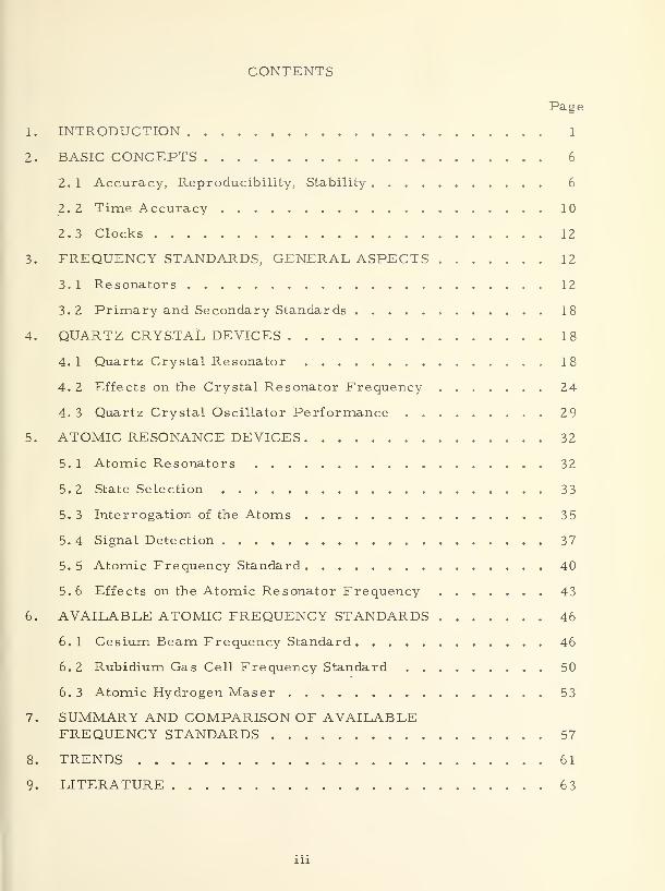
CONTENTS
Page
1. INTRODUCTION 1
2. BASIC CONCEPTS 6
2. 1 Accuracy, Reproducibility, Stability 6
2. 2 Time Accuracy 10
2.3 Clocks 12
3. FREQUENCY STANDARDS, GENERAL ASPECTS 12
3. 1 Resonators 12
3.2 Primary and Secondary Standards . 18
4. QUARTZ CRYSTAL DEVICES 18
4. 1 Quartz Crystal Resonator 18
4. 2 Effects on the Crystal Resonator Frequency 24
4. 3 Quartz Crystal Oscillator Performance 29
5. ATOMIC RESONANCE DEVICES 32
5. 1 Atomic Resonators 32
5. 2 State Selection 33
5. 3 Interrogation of the Atoms 3 5
5.4 Signal Detection 37
5. 5 Atomic Frequency Standard 40
5.6 Effects on the Atomic Resonator Frequency 43
6. AVAILABLE ATOMIC FREQUENCY STANDARDS 46
6. 1 Cesium Beam Frequency Standard 46
6.2 Rubidium Gas Cell Frequency Standard 50
6. 3 Atomic Hydrogen Maser 53
7. SUMMARY AND COMPARISON OF AVAILABLEFREQUENCY STANDARDS 57
8. TRENDS 61
9. LITERATURE 6 3
in

Fig. 1.
Fig. 2.
Fig. 3.
Fig.
Fig-
Fig.
Fig.
Fig. 8
Fig. 9
Fig. 10
Fig. 11
Fig. 12.
Fig. 13.
Fig. 14.
Fig. 15.
Fig. 16.
Fig. 17.
Fig. 18.
Fig. 19.
Fig. 20.
Fig. 21.
LIST OF FIGURES
Definition of time and frequency.
Frequency standard and clock.
Page3
5
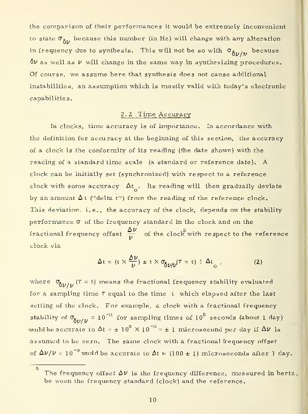
11Relationships between clock accuracy, frequency stability,
and frequency offset. Example (dashed line): for At = 10 ns,
resynchronization every 1 hour is needed, if the frequencystability for 1 hour sampling time is 5 X 10 . The frequency
""12
offset is assumed to be less than 5X10
Example of a clock system (frequency values arbitrarily chosen).
Examples of resonators. 14
Decay time, linewidth, and Q-value of a resonator. 16
Hierarchy of frequency standards. 19
The piezoelectric effect. 21
Principal vibrational modes of quartz crystals. 22
Typical quartz crystal mount. 23
Quartz crystal oscillator. The block diagram shown is not 2 5
necessarily the one giving optimum performance of the crystal
oscillator.
Fundamental and overtone resonance frequencies; example:violin string. (In acoustics, the numbering of the overtones
is done differently: their first overtone 'would be our second,
their second our third, etc. )
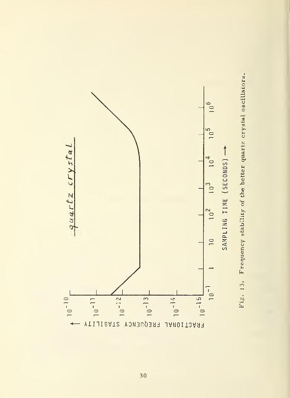
Frequency stability of the better quartz crystal oscillators.
Spatial state selection.
Optical state selection.
Atom detection.
Optical detection.
Microwave detection.
Atomic frequency standard.
Cesium beam frequency standard.
Frequency stability of commercial cesium beam frequencystandards (dashed = performance of improved models in 1971)
26
30
34
36
38
39
41
42
47
48
13
IV

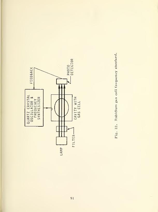
Fig. 22. Rubidium gas cell frequency standard. 51
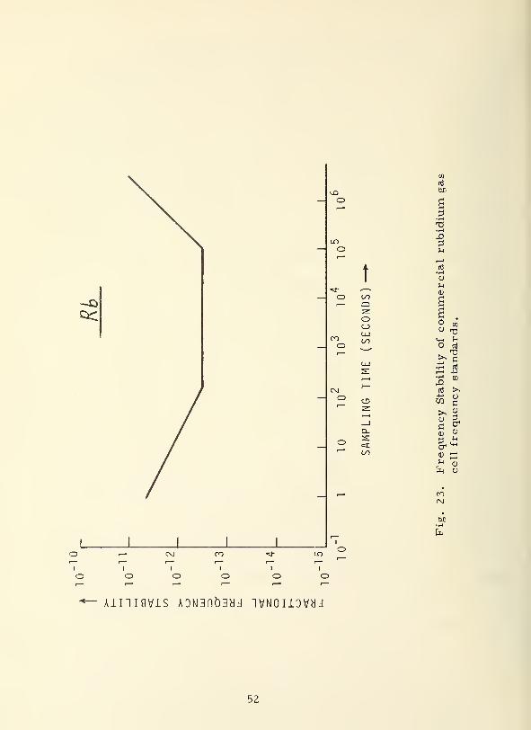
Fig. 23. Frequency stability of commercial rubidium gas cell frequency 52
standards.
Fig. 24. Hydrogen maser oscillator. 55
Fig. 25. Frequency stability of a hydrogen maser oscillator with 56
automatic cavity tuning.
LIST OF TABLES
1. Summary and Comparison of Available Frequency Standards 57-60
2. Additional Promising Items Under Investigation 62

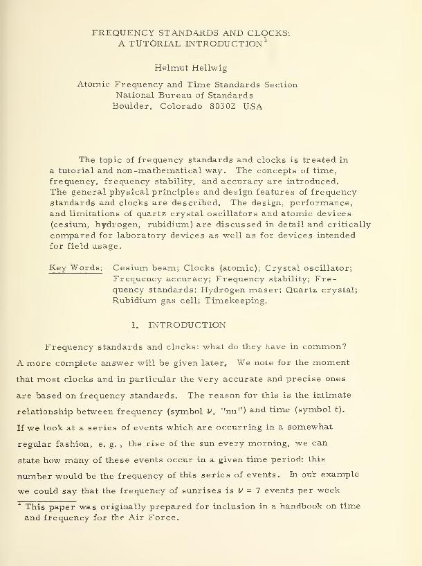
FREQUENCY STANDARDS AND CLOCKS:A TUTORIAL INTRODUCTION 1
Helmut Hellwig
Atomic Frequency and Time Standards SectionNational Bureau of StandardsBoulder, Colorado 80302 USA
The topic of frequency standards and clocks is treated in
a tutorial and non -mathematical way. The concepts of time,
frequency, frequency stability, and accuracy are introduced.
The general physical principles and design features of frequencystandards and clopks are described. The design, performance,and limitations of quartz crystal oscillators and atomic devices
(cesium, hydrogen, rubidium) are discussed in detail and critically
compared for laboratory devices as well as for devices intended
for field usage.
Key Words: Cesium beam; Clocks (atomic); Crystal oscillator;
Frequency accuracy; Frequency stability; Fre-quency standards; Hydrogen maser; Quartz crystal;
Rubidium gas cell; Timekeeping.
1. INTRODUCTION
Frequency standards and clocks: what do they have in common?
A more complete answer will be given later. We note for the moment
that most clocks and in particular the very accurate and precise ones
are based on frequency standards. The reason for this is the intimate
relationship between frequency (symbol V, "nu") and time (symbol t).
If we look at a series of events which are occurring in a somewhat
regular fashion, e. g. , the rise of the sun every morning, we can
state how many of these events occur in a given time period: this
number would be the frequency of this series of events. In our example
we could say that the frequency of sunrises is V = 7 events per week
This paper was originally prepared for inclusion in a handbook on time
and frequency for the Air Force.

or V - 365 events per year. "Events per week" or "events per year"
would be called the unit which we used for our frequency number;
this frequency number is different for different units. In our
example we assumed that we know somehow what a week or a year
is, i. e. , we relied on some external definition for our unit of time.
We can now ask, what is the time between the events? The
answer for our example is simple, one sunrise succeeds the other
after t = — week or t = year where we used "week" and "year"7 36 5
as two possible choices for our unit of time. We can rely on the
regularity and precision of the occurrence of the events, in other
words, on their precise periodicity. Hence, we could define:
the unit of time is one 'week; one week is the time elapsed at the
seventh sunrise following an initial sunrise.
We learned two things: (a) For periodic events, the time
between the events t is related to the frequency V of them occurring
in the following simple way
v-\ (1)
and (b) that periodic events can be used to define time, i. e. , the
generator of the periodic events - the frequency standard - can be
used for a clock. The frequency standard becomes a clock by the
addition of a counting mechanism for the events.
In our example above, the frequency standard is the rotating
earth. The time between recurring events is one day. This fre-
quency standard served mankind for thousands of years and remained
until very recently the source for the definition of time. The counting
mechanism which made it a clock was the recording of years and days.

1 S
ccUJ
T:QOccUJ
o
lu
^>- Oc_> oZL _lUJ oZDO" QUJ LUCC I—
_} '__ U_ <C1
=>S
u_O QiO
00 h-Q <Co ccI—I UJQ£ ^UJ UJQ_ C3
>s
U_ I— uso z:
UJ
UJ UJCO2: a:=> uj
T3
i—
i
o u_l—I UJ OJ
U_ QH-1 1
O _l
a-i-i
UJ _l mQ_ UJ o00 3 r*
<c <c
Z3 ooO ooO o<c Q.
Q
H

The needs to interpolate time from day to day, to get along
for many days -without celestial observations, and to more precisely
measure time-intervals which are very much shorter than a day brought
about the invention of clocks. Although there are other types of clocks
like the sand-clock or the decay in radiation intensity of a radioactive
substance, we shall confine ourselves to the discussion of clocks based
on frequency standards.
The first clocks based on a frequency standard (a pendulum) were
invented about 400 years ago. This type of clock is still most widely
used today. The pendulum may be a suspended weight (gravitational
pendulum) like in "grandfather" clocks or the balance (torsion pendulum)
of modern wristwatches. The objects of our discussion in this report
are today's most advanced frequency standards and clocks; however,
a close look at our traditional clocks will show all the essential fea-
tures which we will recognize again in our later discussion of quartz
crystal and atomic clocks.
The pendulum in our clock is the frequency determining element.
In order to arrive at a frequency standard the pendulum has to be set
in motion and kept in motion: A source of energy is necessary together
with means to transfer this energy to the frequency determining element.
In a wristwatch this source of energy is typically the winding spring,
and the energy is transferred by mechanical means which are controlled
by the pendulum itself (feedback) in order to cause energy transfer in
the proper amount at the proper time in synchronism with the movement
of the pendulum. We now have a frequency standard; the tick frequency of
its pendulum could be picked up acoustically, for example, and used as a
standard frequency. This is actually being done commercially when
adjusting the rate of a clock: the tick-frequency is compared to some
(better) standard frequency. In order to arrive at a clock, a read-out
mechanism is necessary which counts and accumulates the ticks (more

C_> QZKhlli <r>:z> Q Q-oz I—LU <C ZDCC h- Ou. co
i 1
CD^'"^
CD i—i >-^ Z h- <=CUm< J
1 Oh-IQ._i s: rD co
'
1K OD2C5
-— <_}
<c
z: s: z:LU 1—< LUD2Zcr o; lu
<f LU LU 1
CC Y— LU
^ U_ LUQoi I
CQ13LUUJU_
q;>- LU >- LUC3 Li_ CD CJ
LU ZT LU ZDzr <c s: oLU CC LU CO
\—
uo
C
UC
0)
so

accurately: the time between the ticks) and displays the result. In our
example of a wristwatch, this is accomplished by a suitably dimensioned
set of gears and the moving hands on the clockface.
The unit of time today is the second (symbol s). Very much in
analogy to our sunrise example, the second is defined in reference to
a frequency determining element. Since 1967 by international agree-
ment this "natural pendulum" is the cesium atom. One second is
defined in the official wording as the duration of 9192 631 770 periods
of the radiation corresponding to the transition between the two hyper-
fine levels of the ground state of the cesium- 133 atom". Accordingly,
the frequency of the cesium pendulum is 9192 631 770 events per
second (the cesium atom is a very rapidly oscillating pendulum).
Following our eq (1) the unit of frequency is then defined as
hertz (symbol Hz) which means the repetitive occurrence of one event
per second (the use of "hertz" is preferred to the older term "cycle
per second", cps).
2. BASIC CONCEPTS
2. 1 Accuracy, Reproducibility, Stability
The performance of frequency standards is usually described in
terms of accuracy, reproducibility, and stability. We "will use these
terms in the sense of the following definitions:
Accuracy: the degree of conformity of a measured and/ or calcu-
lated value to some specified value or definition.
Reproducibility: the degree of agreement across a set of independent
devices of the same design after adjustment of appropriate specified
parameters in each device.

Stability: the frequency and/or time domain behavior of a pro-
cess. In the time domain (i. e. , the sampling time is the varied
quantity) a frequently used measure of stability is the Allan variance
(to be explained later) or its square root.
It is obvious from these definitions that frequency accuracy
will be largely of interest in scientific measurements and in the
evaluation and intercomparison of the most advanced devices, but
of little or no interest to the average user of frequency standards.
A good reproducibility is an asset in applications where it is
of importance to rely on some degree of conformity of the output
frequency of several devices. The characterization of the stability
of a frequency standard is usually the most important information
to the user. The frequency stability (symbol cr, "sigma") of a fre-
quency standard will depend on a variety of physical and electronic
influences both internal and external to the device which cause
frequency fluctuations. The frequency stability depends also on
the exact measurement procedure which was used to measure the
stability. We shall explain this in the following. Frequency stability
can be measured by taking a reasonably large number of successive
readings of an electronic counter which counts the frequency of the
device to be evaluated. Each counter reading (in hertz) is obtained
by sampling the counted frequency for some specified time, the sampling
time (symbol T, "tau"). This sampling time can usually be chosen by
simply adjusting a knob on the counter; for example, a sampling time of
0. Is or Is or 10s may be chosen.
3In this paper, for tutorial purposes, only the time domain stability is used.
We note, however, that for many scientific applications the frequencydomain stability measure is more useful.

Everyone has had the experience that fluctuations tend to average out
if observed long enough; however, this is not always so. Sigma
will therefore usually depend on the sampling time of the measure-
ment and tends to get smaller with longer sampling times; again,
there are many exceptions to this.
It may be that the fluctuations at some later time are partially
caused by, or depend to some degree on, the previous fluctuations.
In this case, the actual value of a will also depend on the particular
way in 'which the many counter readings are averaged and evaluated.
Also, it will be of influence whether the counter starts counting
again immediately after completion of the preceeding count or
if some time elapses ("dead-time") before counting commences
again.
Finally, electronic circuits will have a finite response time,
e. g. , they cannot follow fluctuations faster than some given rate.
For example, our eye can not register light fluctuations which occur
fester than about every — of a second; using eq (1), we
say that the eye has a frequency response of 10 Hz, or that its
bandwidth is only 10 Hz, i. e. the eye can not follow frequencies higher
than 10 Hz. In order to measure frequency stabilities for sampling
times larger than some value T, we have to provide for an electronic
frequency bandwidth which is larger than —.
We summarize: a recommended way of properly measuring
and describing frequency stability is the following: (a) make sure
that the frequency bandwidth of the total measuring set-up is larger
than— where Tm i n is the smallest desired sampling time; (b)Tmin
use a counter with a dead-time as small as possible ; (c) take a
sufficiently large number of readings at a given sampling time
which is held constant and compute
2
The dead-time should be less than the reciprocal bandwidth; if not,
computation procedures exist to account for larger dead-times.
8

/ addition of the squares of the differences between successive readingsv 2 X total number of differences used
(in the scientific literature this CT is called the square root of the two-
sample Allan variance); (d) repeat (c) at other sampling times T and
tabulate or plot CT as it depends on T.
Commonly, CT will be given as a fractional value, i. e. , the value
obtained for the frequency stability is divided by the carrier frequency.
For example, if a frequency stability of OV =10 Hz were measured at
a carrier frequency of V = 5 MHz (MHz = megahertz = million Hz) then
the fractional frequency stability would be
CT. . = 2 X 10"6.
5v/v
We denote the kind of CT by a subscript, 6y ("delta nu") referring to
6vfrequency fluctuation (measured in Hz) or — referring to fractional
frequency fluctuations (dimensionless). A stability of one part in a
million is thus
CT R , = 1 X 10" S,
and one part in a trillion is written as
%/^ 1X10"12
-
The common usage of the fractional frequency stability cr. ,
instead of the frequency stability CTc (given in Hz) has its good
reasons. In almost all applications of frequency standards their
nominal output frequency will be multiplied or divided, i.e. , the
standard frequency will be used to synthesize other frequencies. Also,
frequency standards themselves will already synthesize several output
frequencies, and different frequency standards will offer different out-
put frequencies. In such a usage of frequency standards as well as in
4The counter readings can be taken in Hz; CT will then have the
dimension of Hz.
the comparison of their performances it would be extremely inconvenient
to state Cr» because this number (in Hz) will change with any alteration
in frequency due to synthesis. This will not be so with Cj. because
6v as well as V -will change in the same way in synthesizing procedures.
Of course, we assume here that synthesis does not cause additional
instabilities, an assumption which is mostly valid with today's electronic
capabilities.
2.2 Time Accuracy
In clocks, time accuracy is of importance. In accordance with
the definition for accuracy at the beginning of this section, the accuracy
of a clock is the conformity of its reading (the date shown) with the
reading of a standard time scale (a standard or reference date). A
clock can be initially set (synchronized) with respect to a reference
clock with some accuracy At . Its reading will then gradually deviate
by an amount At ("delta t") from the reading of the reference clock.
This deviation, i.e., the accuracy of the clock, depends on the stability
performance CT of the frequency standard in the clock and on the
bkV 5fractional frequency offset —— of the clock with respect to the reference
clock via
At = (t x fy ± t x a6v/v
(r = t) + Ato
, (2)
where OV (T = t) means the fractional frequency stability evaluated
for a sampling time T equal to the time t which elapsed after the last
setting of the clock. For example, a clock with a fractional frequency
stability of CT. =10 for sampling times of 1 seconds (about 1 day)
would be accurate to At = ± 10 X 10 =±1 microsecond per day if Ay is
assumed to be zero. The same clock with a fractional frequency offset
of t^VjV - 10 would be accurate to At = (100 ± 1) microseconds after 1 day.
5The frequency offset Al^ is the frequency difference, measured in hertz,
be ween the frequency standard (clock) and the reference.
10
o
t
u
0)
<x> 2o oo
cr
' Q Fh
-z. >-M
o T3c_> c
LO LUnio U~>
o
(XI
o
*— 13SJJ0 ADN3nD3yj "IVNOIlOVHd 'ft/ftV
Ainiavis ADN3nb3yd ivNonovad '(^=X)^/A
jO
1—1 -Oh- tti
<C -l-j
cc mZZ> i—i >*o z (J
zn o co; (U
r— in ?o crz.>- Sh
ooM—
1
cs: >~LU uI— ni
LU h<E 3
uLU u
s: n3
i—
i
Aii— o
c^ 1—
1
u4->
c<u
0>
£-4-i
<D
x>
wa
en
C
rti—
i
0)
Bj
bC•i-H
11

2. 3 Clocks
In the Introduction we discussed that the addition to a frequency
standard of a mechanism, which counts and accumulates and possibly
displays the result, creates a clock.
This task can be performed by a frequency divider which, for
example, derives a frequency of 60 Hz directly from a 5 MHz crystal
oscillator. The 60 Hz voltage can be used to drive an electric clock
similar to those driven by the 60 Hz power line frequency which we use
at home or at work. Or, an additional electric pulse generator may be
used which generates one very sharp electrical pulse per second. The
time interval of 1 second between the pulses (corresponding to a frequency
of 1 Hz) is directly derived from the output of our frequency standard.
The pulses can be directly used in time comparisons with those of other,
similar clocks; or a counter/accumulator can be driven by them.
3. FREQUENCY STANDARDS, GENERAL ASPECTS
3. 1 Resonators
The performance of a frequency standard is to a considerable
degree, but not exclusively, given by its frequency determining element.
It determines the frequency by its resonance behavior. Some examples
for resonance phenomena are (a) a rod, clamped only at one end, which can
vibrate, (b) a block of solid material which can contract and expand
and thus vibrate, (c) a capacitor -coil combination (tank circuit) in
which the electric energy can oscillate back and forth between these
two elements, (d) an antenna (a dipole) where the distribution of electric
charges can oscillate back and forth, and (e) a coil in which an electric
current can create a magnetic field which can oscillate between its two
possible polarities (a magnetic dipole). All these devices have in
common that they can vibrate or oscillate if they are excited. The
method of excitation may be a mechanical pulse for (a) and (b) or an
electrical pulse for (c) or a sudden surge of an electric field for (d)
or of a magnetic field for (e). The devices exhibit a resonance, i.e.,
12
i<i
,—
,
O^v. C£ 1—
1
cc o 1—^LlIH 1 1—OH< ^ IDo -z. _l CO Q-_l => ID O 1—002: _l IDO ID o o— o 11o
<C
OO o_l o^>a. oo zn
r- C£-LUQ.
>-o o;s: luUJ Q=> i—i
LU i—
c
ODiliJf-UJ 00 <O _l Q£"—
" ID LU> Q- Zt—
i
LUQ CJ3
>-O Qz: c£lu <;=> Qo-zlu <:Q£ 1—Ll_ 00
CO
Xou
n!
CD
1
w
bo
13

CD
i—i ^I— CJ<c o.20 CO
+ 1
-H 1 CD 2:
+ 1
i—i LU
A h- h-
T n =r z^ —1 eC
1 1
O _lT i—i UJ
1 +O —IOO O
1 +1 +
O O-i—
i
QOen o r=>
CD C_> oZ I c£i—i o; i—
i
1— O CJ< h-_l i—i ^—^
_l o ^i—
i
<: zO O- <Coo <: h-o <_>—
hO4-1
ni
Coen
cj CD
1—
1
h1— M-t
LU O^
COCD
CD<C =C I—
1
2: ^ £<^ BCD LUZ I—i—i 2: Ht- <c<:_l LU •
_l _l LD
t-t O #
CJ Q- bj)
U~) i—i •tH
O Q h
14
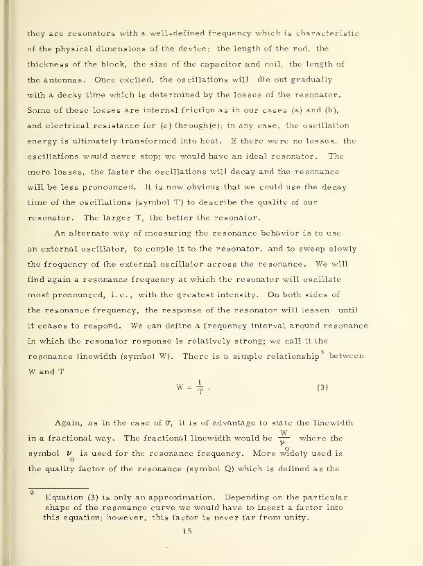
they are resonators with a well-defined frequency which is characteristic
of the physical dimensions of the device: the length of the rod, the
thickness of the block, the size of the capacitor and coil, the length of
the antennas. Once excited, the oscillations will die out gradually
with a decay time which is determined by the losses of the resonator.
Some of these losses are internal friction as in our cases (a) and (b),
and electrical resistance for (c) through(e); in any case, the oscillation
energy is ultimately transformed into heat. If there were no losses, the
oscillations would never stop; we would have an ideal resonator. The
more losses, the faster the oscillations will decay and the resonance
will be less pronounced. It is now obvious that we could use the decay
time of the oscillations (symbol T) to describe the quality of our
resonator. The larger T, the better the resonator.
An alternate way of measuring the resonance behavior is to use
an external oscillator, to couple it to the resonator, and to sweep slowly
the frequency of the external oscillator across the resonance. We will
find again a resonance frequency at which the resonator will oscillate
most pronounced, i.e., with the greatest intensity. On both sides of
the resonance frequency, the response of the resonator will lessen until
it ceases to respond. We can define a frequency interval around resonance
in 'which the resonator response is relatively strong; we call it the
resonance linewidth (symbol W). There is a simple relationship between
W and T
W=~. (3)
Again, as in the case of (7, it is of advantage to state the linewidth
Win a fractional way. The fractional linewidth would be —— where the
symbol V is used for the resonance frequency. More widely used is
the quality factor of the resonance (symbol Q) which is defined as the
6Equation (3) is only an approximation. Depending on the particular
shape of the resonance curve we would have to insert a factor into
this equation; however, this factor is never far from unity.
15

>i
aXIca!
5
o
Q
be
i—i oo
x ;dLU Q_
16

reciprocal fractional linewidth
Q Hw • (4)
In frequency standards we obviously like to have large values for
the Q of the frequency determining element. As an example, if Q = 10,
then a fractional accuracy of 1 would imply that we can determine
the center of our resonance curve to a small fraction (10 or one
hundredth of a percent) of its width. In the same example, a stability
of 10 ~ for some sampling time would correspond to an ability to keep
the frequency to within 10 (one millionth) of the resonance linewidth
around a given value. It is clear, therefore, that the frequency stability
and accuracy of a frequency standard may be expected to become the
better the higher the Q-value of the frequency determining element.
Many kinds of frequency determining elements have been and are
being used in frequency standards. They can be grouped into three
classes
:
mechanical resonators;
electronic resonators;
atomic resonators.
As far as mechanical resonators are concerned we will only
discuss one group in detail, the quartz crystals. Other mechanical
resonators like the pendulum and the tuning fork are of no importance
in today's high performance frequency standards although they have been
historically very important and are still widely used in low performance
devices (e.g., in watches). For similar reasons we will also omit the
discussion of electronic resonators like the tank circuits (our device (c)
of above) and microwave cavities. Atomic resonators form the heart
of our most accurate frequency standards and clocks and will, therefore,
be extensively discussed.
17

3.2 Primary and Secondary Standards
At this point, we should briefly discuss the frequently used terms
"primary frequency standard" and "secondary frequency standard".
These terms should refer to the systems -use of the devices; any fre-
quency standard, regardless of its accuracy or stability, can be a *
primary frequency standard, if it is used as the sole calibration reference
for other frequency sources. A secondary frequency standard is a device
which is occasionally calibrated against a primary frequency standard
but operationally serves as the working reference for other frequency
sources. The use of the terms "primary" and "secondary" to describe
the performance and/or the design of a frequency standard itself is
discouraged. These aspects can be described adequately and accurately
by stating accuracy, reproducibility, and design features.
One class of frequency standards can be separated from the rest.
We call those the evaluable frequency standards, which, by virtue of
their basic physical operation as well as their design, allow the experi-
mental evaluation of all known influences which might alter the output
frequency. The accuracy of the evaluable frequency standard can thus
be stated for the single device without reference to any other frequency
standard. We will discuss it in more detail later in connection with
cesium beam frequency standards.
4. QUARTZ CRYSTAL DEVICES
4. 1 Quartz Crystal Resonator
The quartz crystal is a mechanical resonator much like our
examples (a) and (b) of section 3. 1. The resonator's oscillations have
to be excited and sensed externally. In the case of a quartz crystal this
is done by taking advantage of its piezoelectric properties. The piezo-
electric effect is a special property of a certain class of crystals.

Q>- Cdcc <c<C QS ZM <Can \—Q. OO
>- 1/1
an Q=C anQ <c^ oo 2:o <cUJ 1—00 00
00
cc Oillj <cX OH- z
<t\—00
CTJ
UC(D
cr
u
•r-<
bD
19

Compression or dilatation of the crystal generates a voltage across the
crystal, and conversely, the application of an external voltage across
the crystal causes the crystal to expand or contract depending on the
polarity of the voltage. A crystal is not a homogeneous medium but has
certain preferred directions; thus, the piezoelectric effect has a directional
dependence with respect to the orientation of the crystal. In order to
take advantage of the piezoelectric effect one has to cut the crystal
resonator from the crystal block in a well defined way with respect
to the crystallographic directions. The raw material today is both
natural quartz and synthetic quartz. The crystal is cut out of the
raw crystal in the desired orientation with the aid of optical tech-
niques which allow the determination of the crystallographic axes.
The high precision final orientation of the cut and the tuning to the
desired frequency is then done by grinding and etching under control
of x-ray methods.
The quartz crystal can be cut and electrically excited in a
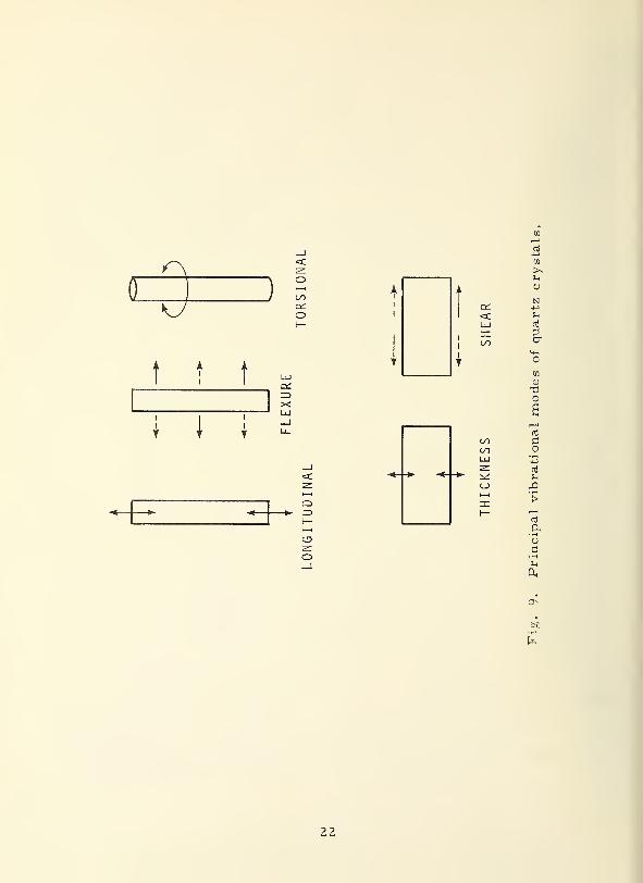
variety of ways. The most common types of vibrations (modes)
are the longitudinal and thickness modes, the flexure (bending)
mode, the torsional mode, and the shear mode. In order to use the
piezoelectric effect, electrodes have to be put on some of the cry-
stal surfaces such that the desired mode is excited. The electrodes
are typically created as extremely thin metallic coatings by vacuum
evaporation of metals. Electric leads are attached to the electrodes,
(e.g., by soldering), which usually also serve as the mounting sup-
port thus freely suspending the quartz crystal. In order to least
perturb the mechanical vibrations of the crystal, the electrode
-
support leads are attached at points where no vibrational motion
occurs (nodes). The crystal is usually encased and the enclosure
is sometimes filled with a protective gas or is evacuated.
20

M _i(— <cOC h-<c ooZD >-cr cc
CJ
+
—
o
1
o—
1
1 J
LU oCD 1—
1
<C h-h- c_>
—1 <CO a:=> i—y;z> oUJ cj»—
<
_l coa. UJQ_ oo<C :r>
«=C
CJ
r
Q.
~iLU COCC =—
!Z> V-
go 1
UJ go oUJ >
Z3 enGO D. (Ogo
1 1J
UJ a \—q; UJ <cO-
i—
i
ex:
_i UJQ. zQ. LU<c CD
o
<4-l
CD
or-l
U
UOJ
0)
ots)
a,
a;
H
Ml
21
ATj
1-
J co
o
CD
o
en
>>U
1
O
SI
Cd 4->
<C Fh
UJ nj
zc 2!
oo cr
mT
m<u
T3
a—
i
rt
CO CCOLU^Z. ni
*• ^ F-i
CJ> J21—1
>reh- i
—
i
rt
a•i-i
ufi
)H
D,
h
22

Q00 UJ —1 CD
LU LU 00 I— <C zz; Q UJ < <_> •—
1
ZD o z cc l-H h- h- h-00 ad ^ lu OL 2: Dd <_)
o i— o es 1— ID O <C 00_l CJ i—i CJ3 O O O Q- H- Qo lu ur =t LU S <C Q- 2T <Cz —1 I— X _l LU !Z> O LUUJ LU ~—'LU LU oS _l OO O _l
I— (—q: 00=C >-ZD Od
'
1
1 ' "
\ L -r;
\>^vavvv.V\
^w^yv--/ • >
1 '• ^
u
u
cr
1—
1
u• r-l
Oh
23
A frequency standard can now be built by adding an electronic
amplifier (energy transfer), feedback, and a power supply. We call
such a device a quartz crystal oscillator. Its output frequency is
determined by the quartz crystal resonator whose frequency in turn is
determined by the physical dimensions of the crystal together with the.1.
properties of crystalline quartz. The resonance frequency thus depends
on the orientation of the cut, the particular mode, and the dimensions
of the crystal. As an example, we find that the resonance frequency
for a longitudinal mode of vibration is approximately given by
V = 2.7 X lCf X \ , (5)o £
where & is the length of the crystal. Equation (5) is 'written such that the
use of meters to express & will give the resonance frequency V in hertz.
Equation (5) allows us to estimate the size of crystals. For example,
a 100 kHz crystal will have a length which is of the order of a few centi-
meters and a 10 MHz crystal will have a length (thickness) of just a few
tenths of a millimeter. We see from this that the production of quartz
crystals with resonance frequencies much above 10 MHz is hardly possible.
However, one can excite resonators not only in their so-called fundamental
mode (which we discussed so far) but also at multiples (overtones) of this
fundamental resonance frequency. The best example for this is the violin
string which also can be caused to oscillate at frequencies which are
multiples of the fundamental frequency; the violinist depends on this.
Quartz crystals which are designed for the excitation of multiples of
their fundamental resonance are called overtone crystals.
4.2 Effects on the Crystal Resonator Frequency
Two-deleterious effects, among others, are important in the design
of crystals and crystal oscillators and limit their usefulness. The first
is the temperature dependence of the quartz crystal resonance frequency,
the second is a slow change of the resonance frequency as time goes on
(drift).
24

o1 i
* )
OL—1 o
N<h-1— 1— =az
q: oo si•=C >- o
'!
ra o; oocrc_> lu
i ,
<cCDQLlJ
LUu_
LU >-i—
i
a: —iU_ LU Q_
3 Q__l O Z3
Q. OO
<C
to
>,1-1
o
a
bo-r-t
25

FUNDAMENTAL
2nd OVERTONE
3rd OVERTONE
4th OVERTONE
oc
VU
<D
o
Ri
fi
oen
<D
0)
Co
>o
S
r—
I
JS
0)
h
26

The temperature dependence is caused by a slight change in the
elastic properties of the crystal with temperature. This can easily be
imagined from the general behavior of matter that the packing density
of atoms increases with lowering the temperature. However, certain
cuts, i.e., certain crystallographic orientations of the crystal, minimize
this effect over a rather wide range of temperatures, most notably the
so-called "AT" and "GT" cuts. Temperature coefficients of less than
one part in 100 million per degree (celsius or kelvin) are possible, in
_gother words, the fractional frequency change will be less than 10 with
one degree of temperature change. Nevertheless, this effect demands
certain precautions in the design of a crystal oscillator if very high
frequency stabilities over longer times (hours or days) are desired
and/or if large environmental temperature fluctuations are to be
tolerated. Hence, crystals are enclosed in electronically regulated
ovens which maintain a constant temperature; in certain crystal oscil-
lators this is done to better than of a degree.
A different solution to the temperature problem is the so-called
temperature compensated crystal oscillator or TCXO. An additional
frequency determining element in the oscillator, which can essentially
be just a small capacitor (see our example (c) of sec. 3. 1), gives
the opportunity to tune the oscillator over a limited range by varying this
additional element. If a temperature sensor is added which causes a
change in this capacitor one can adjust the response in such a way that
the change in resonance frequency of the crystal resonator is just
compensated by a suitable adjustment of the added capacitor. Bimetal
springs have been used which mechanically change the setting of the
capacitor much in the same way as the automobile choke in many auto-
mobiles works. Today, capacitors whose value changes with an applied
voltage (varactors) are used; the applied voltage is derived from a
temperature sensing circuit. The TCXO thus does not necessarily
27
require further temperature control by an oven. However, we see the
drawback of this approach. In adding a further frequency determining
element, the crystal resonator has to relinquish a corresponding part
of its control on the output frequency of the whole oscillator. We,
therefore, realize that the stability performance of a TCXO will degrade
the more, the wider the temperature range of compensation is made.
The long-term stability (days) of TCXO's is therefore below that of
crystals with a good oven control. We find TCXO's in small, usually
portable units of relatively low performance, e.g., for applications
where frequency stabilities from day to day and frequency changes over
some tens of degrees of temperature of not better than 10 are needed.
The drift, or aging, is a common behavior of all crystal oscillators.
It is a nearly linear (uniform) change in resonance frequency with time,
which is almost always negative, i.e., the resonance frequency decreases.
This decrease could be interpreted as an increase in the crystal size
according to eq (5). Many physical mechanisms have been con-
sidered as the cause: contamination of the surfaces (deposition of
foreign material); changes in the electrodes or the metallic plating;
reformation of loose (from grinding and etching) surface material;
changes in the internal crystal structure; etc. ; all of this possibly caused
or enhanced by the vibrating motion of the oscillating crystal. Careful
fabrication and electrode design combined with clean vacuum enclosures
have led over the years to a reduction of the aging to about 10 per day
and better for the best crystals. This aging corresponds to 10 fractional
thickness change, as we can see from eq (5). For a 5 MHz crystal
with a thickness of a little less than a millimeter this aging corresponds
to an absolute thickness change of only 10 of a millimeter or less than
— of one percent of the diameter of an atom. It seems surprising that
mechanical resonators can be built which change their dimension by so
little.
28
Two more effects on crystal resonators are to be considered.
One is its relative sensitivity to gravitational forces and acceleration:
frequency changes will occur because of the stresses in the crystal
caused by these forces. This influence depends on the direction of the
force relative to the crystallographic axes and thus can be minimized
for certain orientations. The magnitude of the effect is typically of the
order of 10 for accelerations corresponding to the earth's gravitation.
The other effect is related to intermittent operation. If a crystal
oscillator is turned off and, after some time, put back into operation
it will not oscillate immediately at the original frequency but will exhibit
first a "warm-up" due to temperature stabilization of the crystal
resonator and its oven and then for some time (as long as many days)
it will exhibit a large but decreasing drift until it reaches its previous
aging performance. The frequency at which it will then operate might
also be substantially different (as compared to its stability and aging
performance) from its frequency before the interruption.
4. 3 Quartz Crystal Oscillator Performance
Crystal resonators have Q-values which are typically in the range
from Q = 10 to almost Q = 10 . These are very high Q-values as com-
pared to most other resonators except, most notably, atomic resonators.
These high Q-values are an essential prerequisite for the excellent
stability performance of crystal oscillators. The best presently available
devices show stabilities of a few parts in 10 for sampling times from one
second to a day. There is some experimental evidence that the stability
is limited not by the crystal resonator but by noise in the electronic
components in the oscillator circuits. This noise (flicker noise) may
possibly be reduced by a special selection of low noise components
(transistors, capacitors, etc. ) and by some special circuit design. Thus
there is a reasonable chance that the stability may reach values of better
29
N
to
ho4-1
nji—i—
i
•rH
<jt> OO CO
o
to
i_n >>
o U
t
u
N
Id
=a- 3o
U~l
cr
1 Q fn
Z-J_>o 4-j
o 0)
n UJ rQo oo
0)1
£UJ *4-<
s: oOvJ
i
—
>.o.i*
1
CJ3i—
i
Z !di—
i
n!
_] j->
Q. to
o 2: >s1
—
<c U00
CD
r—
•i-H
fn
Ainiavis AONBnbayj lvwouovyj
30
than 10 for sampling times of seconds to hours. For times of about
one millisecond or less, the stability is often determined by additive
noise in the output amplifiers and can then be reduced by a (crystal)
filter in the output. The long-term stability beyond several hours
sampling time is determined by the aging and by external influences
such as line voltage variations, temperature fluctuations, etc. A specifi-
cation of accuracy is not very well possible with crystal oscillators.
Without any frequency calibration they possibly can be fabricated via
thickness -determination (not very practical) to about 10 frequency
accuracy. If they are calibrated against a high accuracy frequency
standard they maintain this calibration (accuracy) according to their
long-term stability performance, e.g., a crystal with the low aging of
10 per day will be accurate to a few parts in 10 for the duration of
a year.
We realize, therefore, that crystal oscillators require calibration,
which may be rather frequent depending on the requirements. The fre-
quency adjustments are being made with a small added capacitor in much
the same way as we discussed before in connection with the TCXO. The
most stable ones with the lowest aging rate cost approximately $2000,
have a volume of a few thousand cubic centimeters, and require a power
of about 10 watts. They have an elaborate crystal oven for temperature
control, well-designed electronics, and usually several output frequencies
which are derived from the oscillator frequency with the aid of frequency
dividers and multipliers. These high performance devices presently use
5 -MHz or 2. 5 -MHz crystal resonators with Q-values of a few million.
31

Crystal oscillators which are cheaper and/or smaller are available
in an immense variety of designs at certain sacrifices in frequency
stability and/or environmental insensitivity . Costs can go down to
below $100, sizes to a few cubic centimeters, and power requirements
to less than 0. 1 watt. The reliability of crystal oscillators is usually
not limited by the crystal, the mean time between failure (MTBF) being
that of any electronic circuit of equivalent sophistication.
5. ATOMIC RESONANCE DEVICES
5. 1 Atomic Resonators
The basis of commercially available atomic frequency standards
are resonances in atoms at microwave frequencies (range 1 to 100 GHz,
GHz = gigahertz = billion hertz). Resonances in molecules and resonances
at higher frequencies in the infrared and visible regions have been studied
for frequency standard applications but have not yet led to practical
devices; however, their potential is highly promising (see sec. 8).
We will confine ourselves, therefore, to the discussion of microwave
resonances in atoms. We may picture such a resonance as a little magnetic
dipole antenna as was discussed in our example (e) in section 3. 1. We
will typically deal with a great many of these dipole antennas (atomic
resonators), and we can separate them into two kinds : (1) receiving
antennas, which will absorb energy from a field at their resonance
frequency, much like our TV antenna at home, and (2) transmitting
antennas which will radiate energy at their resonance frequency in a
fashion analogous to the action of the transmitting antenna of a broad-
casting station. A physicist might say that the atoms which act like
a receiving antenna are in the "lower state" and those acting like a
7Of course, this is a simplification.
32

transmitting antenna are in the "upper state" . In a natural ensemble
of a great many atoms (a gas), we will find that the total number of
upper state atoms is nearly equal to the total number of lower state
atoms. This has an important consequence: if this gas is placed in
an external magnetic field, which oscillates at the atomic resonance
frequency, all atoms may resonate; however, nearly half of the atoms
receive (absorb) energy from the field, the other half emit (add) energy
of an equivalent amount to the field. It is obvious that the net effect is
almost zero; the gas as a whole acts as if it has almost no resonance
although the individual atoms each may resonate. From this we see
that in order to observe the atomic resonance we have to change some-
how the relative amounts of the two kinds of atoms; the upper or the
lower state has to be in the majority. The way in which this is done
determines the design of an atomic resonance device, which is the
frequency determining element in our atomic frequency standard.
5. 2 State Selection <
We will now discuss the two most important methods to accomplish
what is called state selection: the change in the relative numbers of the
two kinds of atoms.
(a) Spatial state selection : This method relies on an actual sorting
procedure where the two atomic states are sorted into different directions
in space. One of the states can then be used, the other is discarded.
As an example, an actual system may produce an atomic gas by heating
the substance in an oven to a suitable temperature. The atoms leave the
oven through a hole and form an atomic beam in an adjacent vacuum
chamber. The atomic beam is then passed through a rather strong magnet
8There is a peculiarity with atoms: an atom changes from the upperto the lower state upon emission of a well-defined amount of energy,
and, correspondingly, an atom changes from the lower to the upper
state after receiving an equal amount of energy at the atomic resonancefrequency.
33

oo . I/O
O I—I— <c<C I—
GO
O I—I— <c<C I—
ooI
alCM LU
Q.Q Q-
00
CD
•O
J°KwJc
TOWlf
33 LU<_)
O Qi"—
" ID2T OO oo
PhCO
&0
34

which causes the separation of the beam into two beams, each of them
containing only one kind of atoms. We remember that our picture of
an atom is that of a little magnetic dipole antenna. The magnet exerts
a force on these magnetic dipoles, which point in opposite directions
for the two different atomic states (we note this without further explana-
tion).
(b) Optical state selection : This technique takes advantage of the fact
that the atoms have more than just one resonance. Other resonances
typically correspond to infrared or visible (light) frequencies. We can
excite one of these resonances by shining intense light of the corresponding
frequency on the atoms. If the light is filtered carefully, very mono-
chromatic (one color, i.e., a very well-defined frequency) light is
obtained. If the light frequency is chosen properly, only one kind of the
atoms will resonate. At the same time, this light frequency is too
far away from the corresponding light resonance of the other kind of
atoms. The light resonance can thus "remove" one kind of the atoms
and provide for the desired majority of the other kind.
5. 3 Interrogation of the Atoms
We are now almost in a position to assemble our atomic frequency
standard. We still need some means to observe the atomic resonance.
A microwave cavity is typically used. Such a cavity has microwave
resonances which are determined by its physical size. The (electrical)
losses of this cavity are given by the electrical conductivity of the cavity
material. Such a cavity may have the shape of a cylinder or that of a
box. It resonates in a way quite similar to the working of an organ-
pipe in the case of acoustic waves. The best known example of a micro-
wave cavity is the microwave oven where food is cooked or fried by plac-
ing it into the resonance field of a cavity. In order to observe the atomic
resonance we have to place the state selected atoms inside of this cavity
35

o
eno
LU
CO
-tH
u
1—
1
CO
£
•r-J
<-3 <Ci—i LxJ
—1 CQ
36

and subject them for some specified time to a microwave signal at their
resonance frequency. The microwave signal will change the relative
number of atoms in the two states, e.g., if all atoms were initially in
the upper state we find some in the lower state after the microwave
signal acted upon them for some time (see footnote 8). If the frequency
of the external microwave signal is exactly at the atomic resonance
frequency, this transfer of atoms from one state to the other reaches a
maximum. The center of the atomic resonance is thus found by monitor-
ing the number of atoms in one of the two states and by varying the
microwave frequency until the number of atoms in the lower state reaches
a maximum, or the number of atoms in the upper state a minimum. A
proportional electric signal can be derived which is fed back to the
oscillator generating the microwave signal. Thus an automatic servo
can be built which keeps the oscillator (usually a crystal oscillator)
locked to the atomic resonance.
5.4 Signal Detection
The detection of the effect of the microwave signal on the atoms
can be done in basically three ways, two of which relate to the two
methods of state selection.
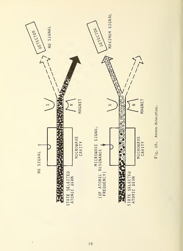
(a) Atom detection : The atoms which leave the cavity as an atomic beam
are passed through the field of a magnet which spatially sorts the two
states. An atom detector is placed to intercept one of these states.
The output of the detector thus indicates the number of atoms in the
upper (or lower) state.
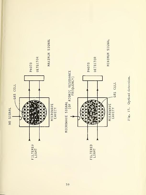
(b) Optical detection : If the atoms are optically state selected, a detector
for light (photo-detector) can be placed in a position such that the light
which has interacted with the atoms is detected. Since the light removes
atoms from one of the states, its intensity will change if atoms which
resonate at the light frequency are added. Such an addition takes place
37
CD fl<"* S •iH
<D-j->
CO
-a
6o
LU <><c >- •
3 h- ^0
O i—i "-t
C£. >c_j <C b£i—i o • rH
s: h
38
cdI—
I
cdI—
I
O ooI—oXQ.
X
_J_lUJO i i > k
C/5
<CD
1
I 2o J3^\ ip • •,-A
_l \ /To - Ia< X^o# saraa •ofllZ r* • QSn •u«UJcd \o o -P-CJ, , ^ w00
oz
i k i k
O l-H
c_> <Ci—
i C->
OI—oXa.
2: >-
on 2:UJ UJ
CJ> UJ1—1 Q£s: u.o
i i j k
I—<
=C u_z oCD —
-
u~>i
1
••aSVd
>3Oen
)\
1—
1
±
j k ^ k
co
i
4-1
uUJ 0>
4_>o <L>
T3t/0
<CC\j
CD U
£
h
a: h-UJ xI— CD
UJa;
39

as a result of the microwave signal which, in effect, transfers atoms
from one state (with no light interaction) to the other (taking part in the
light resonance). The light at the photo -detector therefore is a measure
of the r rnber of atoms in one of the states.
(c) Microwave detection : In this type of detection, the microwave signal
is transmitted through the cavity to a microwave detector. Since the
atoms will either add energy to the signal (if initially in the upper state)
or subtract energy (if initially in the lower state), the microwave power
level at the detector is a measure of the number of atoms changing state.
5. 5 Atomic Frequency Standard
The analogy to our mechanical frequency standard, the wrist watch,
which we discussed in section 1, may now be drawn: the frequency
determining element is the atomic resonator which consists of a cavity
containing the state selected atoms, and some means of detecting the
change in the number of atoms in the two states. A control signal,
related to the number of atoms which changed their state due to the action
of the microwave signal, is fed back to the (crystal) oscillator. The
oscillator and the associated frequency multiplier or synthesizer
correspond to the energy transferring means in our wrist watch (see
sec. 1).
Some power supply has to provide for the energy necessary to
drive the oscillator, multiplier, and possibly the atom state selector.
Very high Q-values can be achieved with atomic resonators. To under-
stand this, we have to recall our eqs (3) and (4).
As we discussed before, good crystal oscillators are available at
frequencies of several MHz; the atomic resonances are at GHzfrequencies. The crystal oscillator frequency therefore has to be
multiplied by a factor of about 1000.
40

STATE SELECTED
ATOMIC BEAM •»««
MICROWAVE SIGNAL(OF ATOMIC RESONANCE
FREQUENCY)
"O
NO ATOMS
_<d JL
MICROWAVECAVITY
MICROWAVERECEIVER
CONSTANT SIGNAL DUETO MICROWAVE SIGNAL
MICROWAVE SIGNAL(OF ATOMIC RESONANCE
FREQUENCY
X7
K^!S$^&$$&&3**3
5bo o°oOl
-O X
MICROWAVERECEIVER
MICROWAVECAVITY
CHANGE IN SIGNALDUE TO ATOMS
Fig. 18. Microwave detection.
41

Oa
( '
a:o
O (——i <xs: 2:
1'
1— 00<=C LU^ ce:O
<:i k
CQQLUUJu_
_l >-<c o1— rv* :?» ryOO O LU LU >->hm-i Qi _Ja; <: o-—
i
LU Q-O 1 LU Q_ 3 Q-
_i o; >—
i
O ZDM i—i U_ h- D. OO1— C_> _l
<c o ^ s:=5 <O"
T3
uC
CD
Ml
42

The Q is related to the time T, which describes the average
duration of oscillations of the resonator. In atomic resonators we find
two chief causes for the termination of oscillations. The first one is
collisions of the resonating atoms with each other and with surrounding
walls; each collision usually terminates the oscillation. The second
one is a rather obvious cause: the atoms may simply leave the region
of microwave signal interaction. In an atomic beam apparatus, the
atoms enter the cavity, traverse the cavity in a certain time, and then
leave the cavity. As an example, let us assume that we have a cavity
of 1 meter length which is traversed by atoms with an average speed of
100 meters per second (a typical value). We assume an atomic resonance
frequency of 10 GHz. The interaction time T is then second, the
linewidth 100 Hz (from eq (3)), and the Q-value is 10 (from eq (4)).
We arrived at a Q-value which is considerably better than that of a
quartz crystal oscillator!
5.6 Effects on the Atomic Resonator Frequency
Before we discuss effects which might cause changes in the output
frequency of an atomic standard, we should make a very important state-
ment: The atomic resonance frequency itself is given to us by nature,
it will not drift or age. Hence, atomic resonators with Q-value s of 1
or higher may be expected to have accuracies of a part in 10 or better
because we will not be able to pull the resonance frequency further away
than the linewidth of the resonance.
In the following, we are not exhaustive but list only the major
perturbing effects:
43

(a) Noise : Random noise in the crystal oscillator, the detector, the
microwave cavity, and the frequency synthesizer will cause corre-
sponding fluctuations of the output frequency.
(b) Cavity pulling : The microwave cavity is itself a resonator. Thus
we have an additional frequency-determining element besides the
atoms. It influences the output frequency by pulling the combined
resonance frequency to a value which usually lies between the
resonances of the atom and cavity. This necessitates the tuning of
the cavity to the atomic resonance. The requirements for tuning
will be relaxed if the Q-value of the atomic resonance is as high as
possible and the cavity-Q as low as possible.
(c) Microwave spectrum; If the exciting microwave signal has not a
symmetric but an asymmetric distribution of frequencies , a fre-
quency pulling occurs which conceptually is related to the mechanism
of cavity pulling. By careful design in the electronics, this effect
can be made negligible.
(d) Collisions : Collisions between the atoms, and between the atoms and
the walls of a vessel (gas cell) in which the atoms may be contained,
will not only shorten the duration of the oscillation but also cause a
frequency shift. Obviously, these effects can be minimized by having
low atom densities and no walls, if possible.
(e) Popple r effect : The apparent change in frequency if the emitter moves
relative to an observer is called Doppler effect. Everybody knows
this for acoustic waves from the experience of an approaching,
whistling locomotive or from automobile racing. Here, the moving
objects are the oscillating atoms and the observer is the microwave
The microwave signal will never be just one single frequency but will
have a certain distribution of frequencies (spectrum).
44

cavity. The Doppler effect can be highly reduced by choosing a
particular direction of the atomic beam with respect to the direction
of the oscillating magnetic microwave field in the cavity; in our
acoustic example, this corresponds to the passing of the whistle at
some large distance instead of having the whistle move directly
towards the observer. An alternate way of reducing the Doppler
effect is the containment of atoms in a region small compared to
the wavelength of the microwave radiation, e.g., by placing a gas
cell inside of the cavity,
(f) Magnetic field : Of the effects which we discuss here, this is the
only one which directly affects the atomic resonance. We remember
that we used a small magnetic dipole antenna as the model for the
atomic resonance. If this antenna is placed in an external static
magnetic field (as that of a permanent magnet) the tuning of the
antenna changes, i.e., the atomic resonance frequency changes.
This necessitates magnetic shielding, which is a characteristic
design feature of all presently used atomic frequency standards.
The shielding is usually quite elaborate and reduces the external
magnetic fields, e.g., the earth's magnetic field, to 1% or less of
its external value. This residual magnetic field can then be measured
quite precisely by using the atomic resonance itself. In fact, the
associated measurement precision is so good that magnetic field
effects do not seriously impair the accuracy of atomic frequency
standards. However, fluctuations of the external magnetic field, or
the movement of the device through a varying field, e.g., as in a
relocation, may perturb the frequency of the atomic standard.
45
Generally speaking, one tries to minimize all of the effects listed
above, and to keep their influence as stable with time as possible.
Such an approach suffices for most applications . For laboratory-
standards, however, where frequency accuracy is the primary purpose,
all effects must be evaluated in a series of experiments, and revalua-
tions must be done occasionally in order to detect changes with time.
6. AVAILABLE ATOMIC FREQUENCY STANDARDS
We will now discuss the design and performance of the three types
of atomic frequency standards which are currently in operational use.
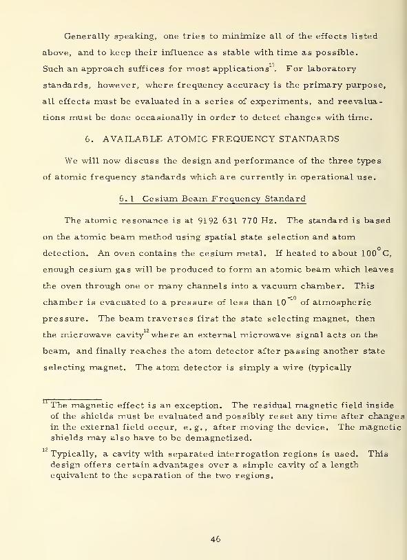
6. 1 Cesium Beam Frequency Standard
The atomic resonance is at 9192 631 770 Hz. The standard is based
on the atomic beam method using spatial state selection and atomo
detection. An oven contains the cesium metal. If heated to about 100 C,
enough cesium gas will be produced to form an atomic beam which leaves
the oven through one or many channels into a vacuum chamber. This
chamber is evacuated to a pressure of less than 10 of atmospheric
pressure. The beam traverses first the state selecting magnet, then
12the microwave cavity where an external microwave signal acts on the
beam, and finally reaches the atom detector after passing another state
selecting magnet. The atom detector is simply a wire (typically
The magnetic effect is an exception. The residual magnetic field inside
of the shields must be evaluated and possibly reset any time after changesin the external field occur, e.g., after moving the device. The magneticshields may also have to be demagnetized.
12Typically, a cavity with separated interrogation regions is used. Thisdesign offers certain advantages over a simple cavity of a length
equivalent to the separation of the two regions.
46
<_>
3Q
OCoI— <_>
=£ LU
Ul LU00 —
'
i— o;w q; > lu>- O O Mq; i— ^ i—i
O ef UJ O0
M —i crznI— i—I LU I—auaz<(/)Ll>do oo
:>
L
ono
s: i—o oh- LU<C I—
LUa
:
[
O
CD
u
<D
03
U
o
47
oI
?H
rt
t)
Oen
o
UO <uO 3
t
a1
*-~.
a=*• OOO o ni
o JO
aro 00CD Cfl
1
—
OLU OS i—
i
1—
'
nj1— •r-H
C\J Oo CD Ut-~ Z <y
i—
i
B
£S o
O =c uOO
•r-l
r—
<
•H
en
1
o pi
co
Ainiavis A3N3nb3yj ivNonovad
48
made from tungsten) whichis heated to about 900 C by passing an
electric current through it. Cesium atoms which impinge on this wire
(which is biased •with a few volts dc) become electrically charged (ionized)
and can be collected on an auxiliary electrode. The stream of electrically
charged atoms at this electrode represents an electric current which is
amplified, detected, and fed into the feedback network.
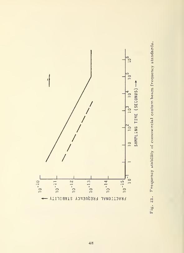
The speed of the atoms and the length of the cavity determine the
Q-value of the atomic resonator. Typical atom speeds are 100 meters
per second. In commercial devices which have to be reasonably small,
the cavity is about 0.4 meter long; the corresponding interaction time
T is four thousandths of a second. From eqs (3) and (4), we cal-
culate a linewidth of a few hundred hertz and a Q-value of a few 10 .
In laboratory devices one can go to very long cavities. Cavities of up
to 4 meters long are used, leading to Q-values of a few 10 . The
fractional frequency stability of both commercial and laboratory devices
reach 10 at sampling times of hours to days. The short-term frequency
stability is limited by fluctuations in the atomic beam intensity which are
basic and unavoidable ("shot noise"). These fluctuations affect the fre-
quency stability less if more intense atomic beams are used. Such
devices, which are becoming available, improve the stability at sampling
11 12times of 1 second from about 5 parts in 10 to about 6 parts in 10 . In
contrast to commercial devices, the laboratory standards are designed
to allow a complete evaluation of all effects on the frequency. Cesium
standards are used extensively where its high reproducibility and unexcelled
long-term stability (sampling times of more than a day) are needed. For
most applications, cesium standards need not be calibrated. They are the
work horses in most of today's standard frequency and time services.
The laboratory standard serves to realize the definition of the second
(see sec. 1).
49

6.2 Rubidium Gas Cell Frequency Standard
The atomic resonance is at 6834 682 608 Hz. The standard is
based on the gas cell method using optical state selection and optical
detection. The gas cell contains rubidium gas at a pressure of only
about 10 of atmospheric pressure. In order to reduce the effect of
collisions among the rubidium atoms, an inert buffer gas (e.g., argon)
is introduced into the cell at a pressure of 1/1000 of atmospheric
pressure. This allows lifetimes of the rubidium atom oscillations
(the oscillation lifetime T is still limited by atom collisions) of about
1/100 second. From eqs (3) and (4) we calculate a corresponding
linewidth of about 100 Hz and a Q-value of several 10 . Atomic collisions
as well as the light and the microwave signal acting simultaneously on the
same atoms cause frequency shifts of the order of 10 . These fre-
quency shifts depend strongly on the composition, temperature, and
pressure of the buffer gas and on the intensity of the light. As a result,
rubidium gas cells vary in their resonance frequency by as much as
10 depending on the particular setting of the frequency shifting parameters
during manufacturing. Since these influences cannot be expected to stay
unchanged as time goes on, rubidium standards need not only initial
calibration but also recalibrations because they exhibit a frequency
drift, i.e., an aging analogous to crystal oscillators. The stability
performance of rubidium standards is nevertheless quite spectacular.
At one second sampling time they display a stability of better than 10
and perform near the 10 level for sampling times of up to a day. For
longer times the frequency stability is spoiled by the frequency drift
which is typically 1X10 per month (much less than the drift of crystal
50
o
iZ 1— LUo ^^•\^ O h-<: ^^^ a: LuCQ ^\^^ D. aQUJLU V
1
!1
11 H 1
_1<oa oih- >- LU / \wo:un / \>- o ^ •—
«
/ \CC \— LU CO
[<—> e^ ^ LU>l
1
_i crnr /M _l LU I— \ /1— i—i CSL -ZL \ /q:uil> V -
<C CO co (
ID o
1u_1—
LUO
—' CO
o
o
g.
u
to
Pi
•r-l
51
-oQC
O
o
<3"
o
COo
CNJ
o
00Qoo
I/O
C\J
I
CD
atUO
•r-<
•H
to
nj
en
o
a1
^1
^3
W!^o
0)
• rH
Ainiavis ADNBnbayj ivNoiiovyj
52

oscillators). Rubidium standards are used where excellent medium-
term stability (minutes to a day) is needed, where its reduced costs,
size, and weight, as compared to cesium standards, are important,
and where a crystal oscillator with its more frequent needs for recalibra-
tions and its greater environmental sensitivity does not suffice.
6. 3 Atomic Hydrogen Maser
The atomic resonance frequency is at 1420 405 752 Hz, The
standard is based on the atomic beam method using spatial state selection
and microwave detection. The beam source is a radio frequency gas14
discharge in molecular hydrogen which produces atomic hydrogen with
high efficiency. The atomic hydrogen beam leaves the source through
one or many channels into a vacuum chamber. The beam then traverses
a state selecting magnet and enters a storage bulb in the microwave
cavity. The storage bulb is made from quartz glass which has low
electric losses and thus does not spoil significantly the cavity-Q.
The storage bulb is evacuated to a pressure of less than 10 of at-
mospheric pressure. Its inner walls are lined with a fluorocarbon
coating, a substance similar to the non-stick coating in cookware.
This coating allows many collisions of the hydrogen atoms with the
walls without significantly disturbing the oscillations of the atoms.
The underlying physical mechanisms are not yet fully understood. The
storage bulb is typically 0. 15 meters in diameter and dimensioned in
such a way as to keep hydrogen atoms for a time of about one second.
Maser is an acronym meaning microwave amplification by stimulated
emission of radiation.
All natural hydrogen gas is composed of hydrogen molecules; eachhydrogen molecule is formed by chemical bonding of two hydrogen atoms,
53

Then they leave the bulb and thus leave also the microwave cavity.
From eqs (3) and (4) we calculate a linewidth of about 1 Hz and
a Q-value of about 10 , the highest Q-value of all presently existing
atomic resonators. If the intensity of the hydrogen beam, which consists
only of upper state atoms (emitting atoms), is sufficiently large and if the
cavity losses are sufficiently low, self-oscillation will start in the cavity;
i.e., the maser itself will generate a microwave signal. We have a
maser-oscillator with an output frequency directly derived from the
atomic resonance. A crystal oscillator can be locked to this frequency
by frequency comparison techniques. As compared to the cesium
standard, the hydrogen maser is not quite as accurate because of
experimental difficulties in the evaluation of the frequency shift due to
the collisions of the hydrogen atoms with the fluorocarbon surface of
the storage bulb. In order to obtain self-oscillation the cavity- Q must
be relatively high. Thus cavity pulling is relatively strong, and it limits
the long-term stability (over times longer than several days) to values
not quite as good as those possible with cesium standards. In the region
from a few seconds to a day the hydrogen maser has the best stability of
all existing standards. Its application is rather limited to uses where
these stabilities are critical and where a rather bulky device is no
handicap. Unlike cesium and rubidium standards, hydrogen masers
have not yet been evaluated under adverse environmental conditions.
The number of hydrogen masers in use is very small compared to the
numbers of cesium beam devices and of rubidium devices.
54
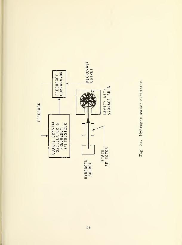
rv c ^>- O cc q.
O 1— O h-
Z <ci—i !Z>
LJ CC s: orD<: "*
O-Q.1 1 1 yCC O WU_ O
1 1
Kri&iTTr
_J „
*
TZ
CRYSTA
ILLATOR
&
EQUENCY
NTHESIZER ] F-cc o cc >-<C/lli.Wr> o n
>- CDI— <C•—i CC> o<C I—<_) 00
o<C O
o
IfCM
C5 OO CCCC 3Q O>- OO
55
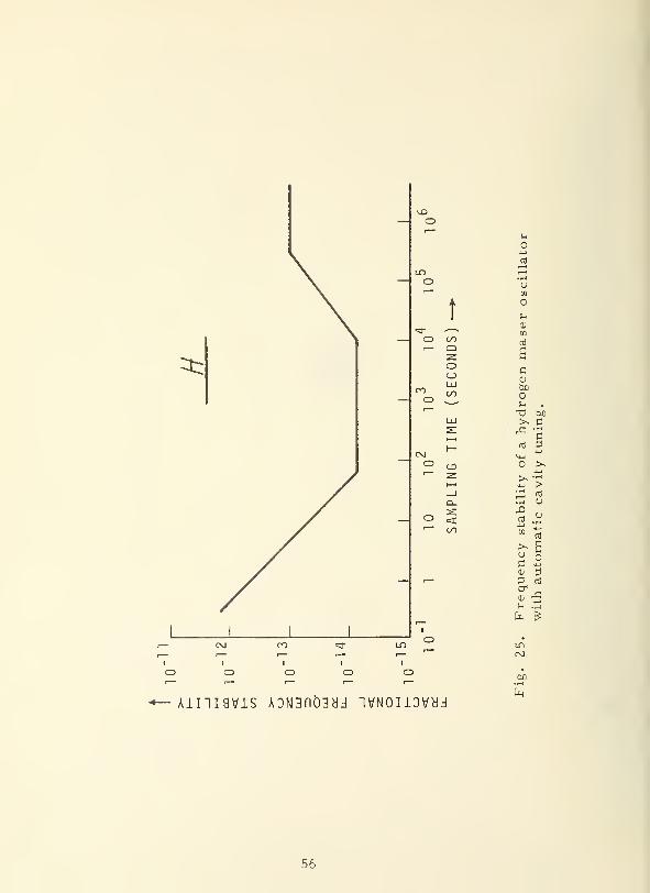
^
O
CD
o ooi— Q
oo
CMo
o <c
All "I I 9VJLS A0N3flt)3cJJ "IVNOUOVHJ
0)
boOu .
T3 bO>s CrC •H
ni 3"+-i
o >*
>> «r-l
>;3 rt
u,Qrt
o
[0ni
s>. ao oa<u 3~
ni
cr0! r£!
h |-|
h £
LD(M
.
00•r-l
h
56

T3(1)
en
en
? CUo 43en
•r4
T3 >>43
en
TJ T)w h CU
QPi
4-1
rd
u< n!
i-ten
PZ
en S3.rH
rd
< >>U c
rd
43
en
CD
"0
rdw a) •t-t u 4-1
>H3cr
1 CU
•iH
> Woz
cuo
cd
CD
uS3
w cu g o cu
D 43 h en3cr1
a " O cu cu
w o ^ fX ^pi cu
4-1 hh en
Oa
^ CD
W•r-4
_. 3
"+H
43
J en
•r4cu
enrd
P3
< cu4-1
CD
43
iHccj
>J u
rd (D<
<><!
Urd ^0_ OS
<+H
O43O
cu i o
h CD o en
S3CU
u • i-t
£43 o
4-1
rd
cu
> Tj ain J-l
CU o
Pi
o 'oo en
3U
<Oh
CD
cu
434-1
rd
a
to4-J
CD
4=
rd
a
re!
u >+H•rH
S3<t3
pO
<D a
£ rd
i—
i
43 a
< n!H3
ni 3m>* £ • t-i
cu
Pi P > 43 •
3 T3 h r_l
^en S3
1-HCD
2Id
rd
en
cu ^O
CDi—
i
43
43re!
Hw >tao
cti
cu
r~: |
43^ H->
cuen S3
3 s'
(d o en
H •H4_)
ocu
en
S3iH
uCD
43
a
S3
a
>^ucCD
a1
CD
hcu
occd
(3
Oen
cu
Pi
CD
OH>CU
D
o
o
j_i en
3 Co o43
• rH
•m W)rj CU
o H
b N5 ffi
CD
4-1
Ocfl
3S3
cfl CU
S3
ni
NI
T3CD
CD
Pm ^^^>* 4_)
^ 53
O Ou
, 1
4-1
rdi-
• r-t
>» uh CO
u o
Xor-
m
CSJ
-;;-
'^L,
rd
rrt
•H MUCU
CD a
a a
£ou
uo 1—
'
(fl
1—
1
o1—
'
Ctf a>•
w H
0)
a4->
o
O43nJ
N
00Ov£>
CM00
enoo
en (Tj
CU CU
U P3
a
•H CD
U43 en
S crt
Pi
N
(Miri
r-
Lfl
o
oCM
CD
$3h
>N4_)
o4-1
cti
to
o43cti
S3
CD
OU•V
ffi S O |
rd
u
en
CD
en
CD
434J
(3
CD
hcS
Ph
J3•men
CD aO oiH> 4->
CD CJ
T3 E3en
cu T)Jh
en CU en
CD Ph f3
43 O O4-) i
—
I
uS3 cu
CU > MM cu CU
cd T) T5Pn >,
S3
j3(3
•rHfl
en
CO <Dcu
4-J o urH •r4
c CD >3 U
cu
T34-)
en
TJ
CD o u4-1
O ao
CU
CL>rd
CD
en434->
4-1
rd
u Uo o T3
»4-4 'H-H CU4-1
en en CD
CD CD CD
3 2 '—
i
—
i
Oeel rd u> > Ph
57

pi nO
d "crt
CD OhCU
riCD
£ a)
4-J M rX0) X 0)
,iJ Oti
Pi •rH
£><CO
4-3
tj01 O
crt
SCD
>>
rdrd
CD U>^ 0)
O Pi
Piu
ft
a*+-i I—
1
• r-J
cn ^D•d CD ctf
4J
a rj CO
u g.S
i—
i
3 H™ Pi
CD A a.
X 2 '
cd S CUO
H ^ sft 5
crt
O31
r^ <-)
ocu
Ct. o
CD a
fco
"
rd «
u i
!>N
rd rg
'cd
p<
Pi
CD
> CD
CD cCO
u
O
CU
CO
> pi
CD Oto ^
i i
o o
X Xin ^h
i i
o o
X X
i i
o o
X XCM r-H
I I
o o
X Xco —
i
pi
(Ti CD
PI (3
O OUJ 4< t
1
CD
Pi d CU
u *4-l
u encrt
4_i C)cu crt
>s c 4_i
Pi o pi
O u CD
4H4_)
h!
1) po
bo(1) u
Pi •T-t
Ti >OJU
Pi pi
<J ctJ CD
CD CO
> HCD cd
en t3
CD g
g S
I I
O O
X Xr- —
<
X Xun vjo
CD
" tiCD 2>, ,3
O >C CD
X X
en
Pi CD
g S3
S ^
O CD >>
3 .ti £PI £
• r-i -r-l 4-J
tj J3 PI
g rd CDU 4J j_,
" Mid
Ohcd
S'3Pi cub£)
2 > :.
5P s o<, CU CO
cd13"
o
X
o
X
o
X
o - aPi Pj CD
O O V)
rd cd
13PI
cd
Xbo
^ 13 CU
bo Pi
<3 £
dCD S
-. cu
>, o
U CD
CD
rri 4-1
O CUs
' CO
CD t*H
rd
!^CD
>CU
AC)
cu
rdcu
O VH4-1
oCO PI
cl
o cm•iH P4-1
rda <u
Arn
i—
i
CO
cdrri
o Pi
CDCU >-U
PI pi ^4
CI) tinHi
im
4-»
m o>> u
cu
13H CD
Pi
CU crtrd
U 4-1j !
"5
crcu
u
CD
CM
X)CU
"rd
CD
aaPi
a CU
4J
CU
TICD P
4-1
ucd
rn en cd
rdrO
rri
pl viT) O(U P.
4J
-71 m cd
M <U Arri ^i
bfj Pi Ccu O OU O X!
cu X1rC V
O X pi
en *UJ
en
cd > cd
Pio cu
crtcd X
opi
4-1
rrt CJ Pl
a urd
crt Ticu cu
CU
scu
crt
H 4J CP

J2nj
H
CO LQ
1) cu1—
'
- M „ bo „ wni
BCU
gB
S-i w
en
(1)
ao en
Bni en
- cu
en ^cu 3
Cfl
u
oen *B
cuu cu
> CU
- rBen 73B
T3i—
i
cu
-O en
<4-t 60cu CU
• l-t 00 en -h bo1 ..-C S ='
c
^4-1 U-i B co 'j-i g*— 5
ni
X cu
>13 5 V cd <U O ni
H ^3
£ " en X! U* CU
<ucu
u gni cu
cuo a
cuB cu B cu u B B cu o B cu
.ft
UB
ft
uH CO
ni .
nj
boni
s 1 ni ^ g ni
cu
J3
cu
s
H
u
en
>sUO
boB
bO""
B CU
O bo
boC
!h ftcu en
ft
g g 2 ga B w » .2 W B * & 5
^o -
B0)
3cr .
0) ?"•
n 2 ^_^
ft 21 1 "T
o^j
p-i ^ B o O o o O oCO u
nj I-H l—
I
B u.2 <
cu
XCM
Xin
X Xin —h
Xin
XCM
o en
nj USh
ft
CU
s* %?B
BoV ~H
3 £ ni<4-l
cu rn3B
u s> cd
ft 'u £ --.
^ 3 3 £* H 2 o 2cd T3 CO 1 i 1 1
B O <! O O o o O OU >—
<
^^ r-H ^H -—
t
r-H
^ fr X X X X X Xo <u
cd Pi—
'
CM UP) rH -1 in
f-n
ft
3
B CU o c
e-
4-> O X -*J
4J B en 3MH
^ enCm en en
Q CU—
' ni cu
>* . J ' *
,B ^ ° ^ L,BOJ
cr —~
Sh Boi ni
T3
1CU
3
Uoo
B
a
£ CU
2 sft bo >> u fn
ni A-g ni ^ ni rv
- <j ni cu CU ^J g cu (j OJ
cd—
'
a a CU I «-l ft CU 1
B fH a H lO~~" -l-> o -^^H if °
cu ^-i s-1
ni_,
• fH
ft o O O T3 T3X CU o Ti
XCU en cu ^
nj
ft
CT>
O Xin
X X—i in
C
55
f-H J
3
ucu
XZ o
cu
cboCO
g
—cu
cd
ft
59
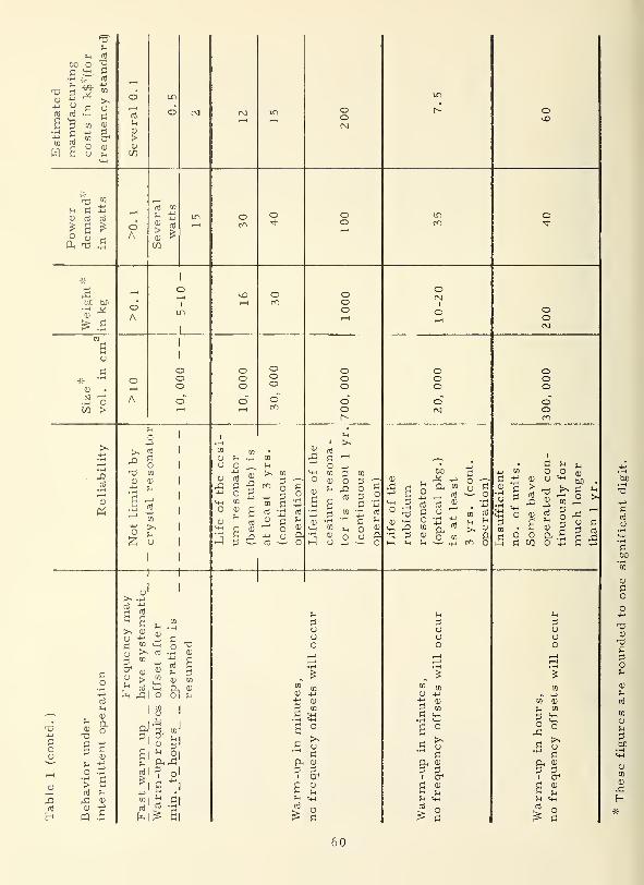
Estimated
ma
nufacturing
costs
in
k$
v
(for
frequency
standard)
ooj
Ucd
>CD
W
in
o CM CO in oo
in
ovn
Powerdemand"'
in
watts
oA
oj to
S ">
CD !>
CO
inr—H
oen
o oo
in O
X,bo tuo o
A
1
o1
in
1
kD o ooor—
1
oCM
1
O ooCM
Size''"
i
•
3
vol.
m
cm
o
A
1
1
oooo
oooo"
OOoo"
ooooo
Oooo
OOOo"Oen
Reliability
u
4-1
>s 5n S"^ OT) to
CD CD
S 13
CO
~ >^
2 o
1
Life
of
the
cesi-
um
resonator
(beam
tube)
is
at
least
3
yrs
.
(continuous
operation)
Lifetime
of
the
cesium
resona-
tor
is
about
1
yr.
(continuous
operation)
Life
of
the
rubidium
resonator
(optical
pkg.)
is
at
least
3
yrs.
(cont.
operation)
Insufficient
no.
of
units.
Some
have
operated
con-
tinuously
for
much
longer
than
1
yr.
Table
1
(contd.
)
Behavior
under
intermittent
operation
>> .H
a |>> cu
£ TO
0) •**
3 <"
& cdcu ^
Oh
£
cd
sWarm-up
reqiires
offset
after
min.
to
hours
operation
is
X)CD
a
TO
2TO
CD4-1
c•r-4
a
.2
1
aunj
u
I—
1
1TO
CD
TOmm
>>ocCD
CD
a
u
ooo
1—
1
m enCD 4J
R ma
°
.5 u
i crC a>
u
oo
i—*
i—
i
'%
TO
en CD
^ TO
1°
d CD
£ ^
1 2
60
8. TRENDS
All devices which were discussed in this report have improved
over the past years in one or more of the following aspects: reliability,
size, weight, stability performance, and environmental insensitivity.
A considerable amount of effort is still being expended to go further in
this direction; however, it would be inappropriate here to try to estimate
the improvement of performance specifications which might (or might
not) be achieved in the future.
There are several other devices, designs, and concepts which
have been studied or are being investigated with some potential for
future use in frequency standards. Most of these are summarized in
Table 2.
61
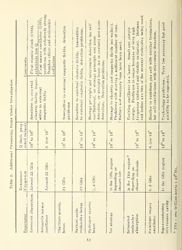
00
00- fi
lti £ n)
Q^ en Tj
ci t>. yXT <0
1h CU -"fi
O > 2
° a u1h
TOH
O A u
cu
en ,£)
U Oftft
u °
C
en
"5 -«ni
fi tn
U TJ
cu X
cu £
(0
00rt3
CD
TJ
Tl
CU
Pi
60ni
CD
en cu
fi"'
tn ?
en «C 5cu
£ ft
C. o
en -h
2 yD ^£ CD
O^
y 22 <u
3 £
CD M
ni
cu fi
> J-.
s -tn >^
a <"
<u o
o
§ I"'Si <fl
O t-,
i! CCD rt
ft
o
nl
TJCtO
CU
>ni O
£ .fi3 £(-i tu
CU u
,fi fi
00 O
&. O m jj
Tfstfl
u -
.S Vu Cft o
y ""S
c3Q
u utu tu
CU CU
TJ TJ
en £i-i Oi—
'
*i-i
<$ K-i
£ o
o ?-.
fi tu— £>
2 3B coj CU
"fi CU
O CU -Q
CJ CU
>ni
fi ,fi
CU
fi ^00^
a
TJfi
rti >>ufi
O r; CU
2 * 6« '%
tjfi en fi
'H C ni
tu fir.
ooi> Sni ^ fi
* O £
tu
cni
0) ,fi rfi—' 60 "ft -m CU
c ^ 5
•a «c >ni ^_ O
ni
CO nj
O
CU
en TD^ ni
tu
5 ni >
a 3C
tn C ni
J2cu
2 2
rf
u^2 t4H CU
cd
o Hh >> CU
60 o f-l
fifi Ti
fi cu oj-> OX) fi
U tn
cutu
fi
W T <4H ni
tu
CU
>ni
O
<U C
ni
MS
• i-i
-^fi :
rt cu1 rn
.3 fi
oo00
~0
CU
,2 ft
2 *o ^*
tU
^ o
o ^fi £
tu nj
OIn
ft!
>O
a
o
cu
<
o
o
o
o
o
eoO
O
o
COO
O
ou01O
CU
<!
o
o
o
Ccu
ufi fi
ni cu
en tu
cu
SI
Xa
fi
fi
o
fi
o O a
at O0tu CU
M i-i 1-1
n fi SI
K 0JJ o S3n •i-i H
Td fi
cu fi cu tu
rfi cu en ^4-1
ft Oa cu rfi ci—
i
T3 O
eu
3c yo 200 2c £
TJ fi
jd CU
tu en
a ocu xTJ CJ
S3
O
fi
o00cu
In
NI
S3acu
,fi
o
t$
fi
oen
cu
C4
^2nj
•H Ofi "O "J
S5£ u« tn
<! o
ss5 niAh CU
00
-^ tU
S3 -Q
cu
00ni
uo
TJCU ^J
ni tj
O
ft
ni g -^-0 P niW
•H (ti
TJ pj
| y"' CD
ft o
00 %c >Ti ni
cj y
TJcooutu
3
62

9. LITERATURE
The following references are a limited selection. They are intended
as a guide for those who wish to penetrate the subject in greater depth.
A. Introduction
(1) J. Kovalevsky , "Astronomical Time", Metrologia 1 (1965)169.
(2) H. M. Smith /'International Time and Frequency Coordination",
Proc. IEEE 60 (1972) (to be published).
(3) The American Ephemeris and Nautical Almanac , U. S. GovernmentPrinting Office , Washington, D. C.
(4) P. P. Viezbicke, "NBS Frequency and Time Broadcast Services"
NBS Special Publication 236 (1971).
B. Basic Concepts
(1) D. W. Allan, "Statistics of Atomic Frequency Standards, "
Proc. IEEE 54 (1966) 221.
(2) J. A. Barnes et al, "Characterization of Frequency Stability"
IEEE Trans, on Instr. and Meas, IM-20 (1971) 105.
(3) L. S. Cutler and C. L. Searles , "Some Aspects of the Theory andMeasurement of Frequency Fluctuations in Frequency Standards, "
Proc. IEEE 54 (1966) 136,
C. Frequency Standards, General Aspects
(1) Most general physics textbooks.
(2) A. E. Siegmann, "An Introduction to Lasers and Masers'JChapter 2, McGraw-Hill 1971.
D. Quartz Crystal Devices
(1) E. A. Gerber and R. A. Sykes, "State of the Art - QuartzCrystal Units and Oscillators," Proc. IEEE 54 (1966) 103.
(2) E. A. Gerber and R. A. Sykes, "A Quarter Century of Progressin the Theory and Development of Crystals for Frequency Control
and Selection, " Proc. 2 5th Annual Symp. on Frequency Control,
Ft. Monmouth, N. J. (1971) 1 (available from Electronic Industries
Assoc. , Washington, D. C. ).
(3) R. A. Heising, "Quartz Crystals for Electrical Circuits, "
Van Nostrand, 1946.
63

Atomic Resonance Devices
(1) N. F. Ramsey, "History of Atomic and Molecular Control of
Frequency and Time, " Proc. 25th Annual Symp. on FrequencyControl, Ft. Monmouth, N. J. (1971) 46 (available from Electronic
Industries Assoc. , Washington, D. C. ).
(2) N. F. Ramsey, "Molecular Beams, " Oxford, 1956.
(3) A. E. Siegmann , "An Introduction to Lasers and Masers",McGraw-Hill, 1971.
Available Atomic Frequency Standards
(1) A. O. McCoubrey , "A Survey of Atomic Frequency Standards, "
Proc. IEEE 54 (1966) 116.
(2) D. Kleppner, H. C. Berg, S. B. Crampton, N. F. Ramsey,R. F. C. Vessot, H. E. Peters, and J. Vanier, "Hydrogen-MaserPrinciples and Techniques, " Phys. Rev. 138 (1965) A97 2,
(3) R. E. Beehler, R„ C. Mockler, and J. M. Richardson, "CesiumBeam Atomic Time and Frequency Standards, " Metrologia 1
(1965) 114.
(4) P. Davidovits and R. Norvick, "The Optically Pumped RubidiumMaser',' Proc. IEEE 54 (1966) 155.
G. Trends
(1) H. Hellwig, "Areas of Promise for the Development of
Primary Frequency Standards, " Metrologia 6 (1970) 118.
(2) H„ S. Boyne, "Laser Frequency Stabilization Techniques andApplications," IEEE Trans, on Instr. and Meas. IM-20 (1971) 19-
64
ACKNOWLEDGMENTS
The author wishes to thank Byron E. Blair for his assistance in
setting up the basic outline of this paper, and Donald Halford and David
W. Allan for their assistance in the preparation of this paper.
65


form NBS-114A (1-711
U.S. DEPT. OF COMM.BIBLIOGRAPHIC DATA
SHEET
1. PUBLICATION OR REPORT NO.
NBS Technical Note 61
6
2. Gov't AccessionNo.
3. Recipient's Accession No.
4. TITLE AND SUBTITLE
Frequency Standards and Clocks: A Tutorial Introduction
5. Publication Date
6. Performing Organization Code
7. AUTHOR(S)
Helmut Hellwig8. Performing Organization
10. Project/Taslc/Work Unit No.
27304189. PERFORMING ORGANIZATION NAME AND ADDRESS
NATIONAL BUREAU OF STANDARDS, Boulder Labs.DEPARTMENT OF COMMERCEBoulder, Colorado ;80 302
11. Contract/Grant No.
E111M-6
12. Sponsoring Organization Name and Address
U. S. Air ForceRichards Gebaur Air Force Base
Missouri 64030
13. Type of Report & PeriodCovered
14. Sponsoring Agency Code
15. SUPPLEMENTARY NOTES
16. ABSTRACT (A 200-word or less factual summary of most significant information. If document includes a significantbibliography or literature survey, mention it here.)
The topic of frequency standards and clocks is treated in a tutorial and non-mathematical way. The concepts of time, frequency, frequency stability, andaccuracy are introduced. The general physical principles and design featuresof frequency standards and clocks are described. The design, performance,and limitations of quartz crystal oscillators and atomic devices (cesium, hydrogen,rubidium) are discussed in detail and critically compared for laboratory devicesas well as for devices intended for field usage.
17. key WORDS (Alphabetical order, separated by semicolons) Cesium beam; Clocks (atomic); Crystaloscillator; Frequency accuracy; Frequency stability; Frequency standards; Hydrogenmaser; Quartz crystal; Rubidium gas cell; Timekeeping
18. AVAILABILITY STATEMENT
FH UNLIMITED.
I IFOR OFFICIAL DISTRIBUTION. DO NOT RELEASETO NTIS.
GPO 84 1 - 530
19. SECURITY CLASS(THIS REPORT)
UNCLASSIFIED
20. SECURITY CLASS(THIS PAGE)
UNCLASSIFIED
21. NO. OF PAGES
22. Price
$.65
USCOMM-DC 66244-P7?

NBS TECHNICAL PUBLICATIONS
PERIODICALS NONPERIODICALS
JOURNAL OF RESEARCH reports National
Bureau of Standards research and development in
physics, mathematics, chemistry, and engineering.
Comprehensive scientific papers give complete details
of the work, including laboratory data, experimental
procedures, and theoretical and mathematical analy-
ses. Illustrated with photographs, drawings, and
charts.
Published in three sections, available separately:
• Physics and Chemistry
Papers of interest primarily to scientists working in
these fields. This section covers a broad range of
physical and chemical research, with major emphasis
on standards of physical measurement, fundamental
constants, and properties of matter. Issued six times
a vear. Annual subscription: Domestic, $9.50; for-
eign, $11.75*.
• Mathematical Sciences
Studies and compilations designed mainly for the
mathematician and theoretical physicist. Topics in
mathematical statistics, theory of experiment design,
numerical analysis, theoretical physics and chemis-
try, logical design and programming of computers
and computer systems. Short numerical tables.
Issued quarterly. Annual subscription: Domestic,
$5.00; foreign, $6.25*.
• Engineering and Instrumentation
Reporting results of interest chiefly to the engineer
and the applied scientist. This section includes manyof the new developments in instrumentation resulting
from the Bureau's work in physical measurement,
data processing, and development of test methods.
It will also cover some of the work in acoustics,
applied mechanics, building research, and cryogenic
engineering. Issued quarterly. Annual subscription:
Domestic, $5.00; foreign, $6.25*.
TECHNICAL NEWS BULLETIN
The best single source of information concerning the
Bureau's research, developmental, cooperative andpublication activities, this monthly publication is
designed for the industry-oriented individual whosedaily work involves intimate contact with science andtechnology
—
for engineers, chemists, physicists, re-
search managers, product-development managers, andcompany executives. Annual subscription: Domestic,
$3.00; foreign, $4.00*.
• Difference in price is due to extra cost of foreign mailing.
Applied Mathematics Series. Mathematical tables,
manuals, and studies.
Building Science Series. Research results, test
methods, and performance criteria of building ma-terials, components, systems, and structures.
Handbooks. Recommended codes of engineering
and industrial practice (including safety codes) de-
veloped in cooperation with interested industries,
professional organizations, and regulatory bodies.
Special Publications. Proceedings of NBS confer-
ences, bibliographies, annual reports, wall charts,
pamphlets, etc.
Monographs. Major contributions to the technical
literature on various subjects related to the Bureau's
scientific and technical activities.
National Standard Reference Data Series.
NSRDS provides quantitative data on the physical
and chemical properties of materials, compiled from
the world's literature and critically evaluated.
Product Standards. Provide requirements for sizes,
types, quality and methods for testing various indus-
trial products. These standards are developed coopera-
tively with interested Government and industry groups
and provide the basis for common understanding of
product characteristics for both buyers and sellers.
Their use is voluntary.
Technical Notes. This series consists of communi-cations and reports (covering both other agency and
NBS-sponsored work) of limited or transitory interest.
Federal Information Processing Standards Pub-lications. This series is the official publication within
the Federal Government for information on standards
adopted and promulgated under the Public Law89-306, and Bureau of the Budget Circular A-86entitled, Standardization of Data Elements and Codes
in Data Systems.
Consumer Information Series. Practical informa-
tion, based on NBS research and experience, covering
areas of interest to the consumer. Easily understand-
able language and illustrations provide useful back-
ground knowledge for shopping in today's technolog-
ical marketplace.
NBS Special Publication 305. Supplement 1,
Publications of the NBS, 1968-1969. When order-
ing, include Catalog No. C13. 10:305. Price $4.50;
foreign, $5.75.
Order NBS publications from: Superintendent of DocumentsGovernment Printing Office
Washington, D.C. 20402
U.S. DEPARTMENT OF COMMERCENational Bureau of StandardsWashington. D.C. 20234
OFFICIAL BUSINESS
Penalty for Private Use. $300
POSTAGE AND FEES PAIDU.S. DEPARTMENT OF COMMERCE


![DE])ARTMENT OF WOMEN AND CHILD …it.delhigovt.nic.in/writereaddata/Odr201684584.pdf(Ci) PLAN-BUDGET Time Bound/Most Urgent DE])ARTMENT OF WOMEN AND CHILD DEVELOPMENT GOVERNMENT OF](https://static.fdocuments.us/doc/165x107/5e8df290629e953c7e1e2807/deartment-of-women-and-child-it-ci-plan-budget-time-boundmost-urgent-deartment.jpg)