NAVSEA AD7714YRU Total Dose Test Report - NASA · NAVSEA AD7714YRU Total Dose Test Report Final...
63
NAVSEA AD7714YRU Total Dose Test Report Final Report Prepared for: NASA GSFC Code 562.1 GreenBelt, MD 20771 Prepared by: NAVSEA Crane - Surface Warfare Center Division John Bings, March 29, 2002 Code 6054, Building 2088 300 Highway 361 Crane, IN 47522-5001
Transcript of NAVSEA AD7714YRU Total Dose Test Report - NASA · NAVSEA AD7714YRU Total Dose Test Report Final...

NAVSEA AD7714YRU Total DoseTest Report
Final Report
Prepared for:NASA GSFCCode 562.1GreenBelt, MD 20771
Prepared by:NAVSEA Crane - Surface Warfare Center DivisionJohn Bings, March 29, 2002Code 6054, Building 2088300 Highway 361Crane, IN 47522-5001
Surface Warfare Center Division

1
Summary
NAVSEA Crane Division performed total dose testing on Analog Device’s AD7714, 24 bit analog-to-digital converter. Two devices were statically biased, three dynamically biased. Results of thetotal dose testing indicate:• Both devices biased statically and all three devices biased dynamically failed and became
non-functional between 10Krad(Si) and 20Krad(Si).• Both devices biased statically and all three devices biased dynamically began showing
degradation between 10Krad(Si) and 20Krad(Si) as evidenced by increasing power supplycurrents.
• Both devices biased statically and all three devices biased dynamically performed tospecified effective resolution of greater than 17 bits up to 10 Krad(Si).
• Both devices biased statically and all three devices biased dynamically showed nodegradation in integral nonlinearity up to 10Krad(Si).
• After the 168 hour biased room temperature anneal, all five devices remained nonfunctional.
Introduction
Purpose
This testing was performed to gather parametric and radiation hardness performance informationon the AD7714YRU for NASA.
Background
The AD7714 is a commercial 24 bit 500uA sigma-delta signal conditioning analog-to-digitalconverter (ADC) manufactured by Analog Devices using their CMOS process. See Appendix Bfor the device specification sheet.
Test Samples
A total of five AD7714 (serial numbers 1, 2, 3, 4 and 5) were tested. All devices had a date codeof 0041. All specifications were taken from the device specification sheet with the exception ofthe Effective Resolution, which was provided by NASA.
Table 1 gives a summary of the AD7714 specifications of interest.
Test Symbol Specifications
Analog Supply Current [A] IAVDD <1.1mAAnalog Supply Voltage[V] AVDD 5.0VDigital Supply Current [A] IDVDD <0.35mADigital Supply Voltage [V] DVDD 5.0V
Effective Resolution ER >17Standby Current <0.018mA
Integral Non Linearity INL +/- 0.001% of FSR
Table 1 – AD7714 Specifications of Interest(Refer to AD7714 Specification in Appendix B for further information.)
Facilities
All testing was performed at NAVSEA Crane, using a Shepherd Model 484 Cobalt-60 tunnelirradiator.

2
Test Setup
The parameters Effective Resolution (ER), Integral Non-Linearity (INL), digital (operating andstandby) and analog power supply currents (IDVdd, Idstby, and IAVdd) and DC Parameters (Voland Voh) were measured using an HP 82000 Automatic Test System before radiation wasapplied, after each dose increment and following anneal. Power supply currents were monitoredduring irradiation and verified using an Agilent 34401A multimeter before each dose increment,after each dose increment and after 82000 testing before the following dose increment. Alldevices were retained for possible failure analysis and future testing.
Two devices were tested with a static bias applied during radiation and three devices werelikewise tested with a dynamic bias applied. The statically biased devices were irradiated withnominal DC power applied and all inputs available grounded. Dynamically biased devices usedthe same nominal DC power as the static condition with the addition of a 2.4576 MHz clock. Inboth cases the Sclk signal was grounded to force the device to remain in a consistent operatingstate during irradiation. Testing required dose increments of 2.5, 5.0, 7.5, 10.0 and 20.0Krad(Si)dose increments and a 168 hour anneal period after irradiation. All testing was conducted at adose rate of 0.86 rad/s. This was verified during dosimetry and checked during the 2.5Krad(Si)dose increment.
The bias conditions used for total dose tests were as follows:Dynamic: DVdd = +5.0V AVdd = +5.0V Vref = +2.5V Mclk = 4.5 Volts (0 to peak) at 2.4576 MHz Sclk = GND Ain = GND
Static: DVdd = +5.0V
AVdd = +5.0V Vref = +2.5V Mclk = GND Sclk = GND Ain = GND
Vol was measured by forcing Mclk into a zero state. Voh was measured during Drdy signal highstate.
Several boards were manufactured to facilitate this radiation hardness testing. Five smalldaughter boards (see Figure 1 for a representative daughter board) were manufactured to allowthe AD7714 devices to be surface mounted with standard pins on 100 mil underneath. A biastest board (see Figure 2) with five daughter board sockets was generated to be used in theSheppard irradiator to allow static and dynamic bias conditions to be maintained duringirradiation. An 82000 test board (see Figure 3) with one daughter board socket was made toallow the 82000 to connect to all the necessary leads of the AD7714 required for parametric andfunctional testing.

3
Figure 1 - Test Daughter Board with Size Reference
Figure 2 - Irradiated Bias Test Board with Daughter Boards Mounted

4
Figure 3 – 82000 Tester Interface Board with Daughter Board Mounted
The digital and analog bias voltages of 5.0V for both the static and dynamic conditions wereprovided by an HP6626A System DC Power Supply during irradiation. Likewise, an AgilentE3631 Triple Power Supply provided the Vref voltage for both static and dynamic conditions. TheMclk Signal (dynamic condition) was generated from an HP 3325A Synthesizer/FunctionGenerator set to output a square wave (4.5V with a 2.3V offset) that was 50 ohm terminated atthe board. This signal was checked to verify no noticeable overshoot or negative voltages wereapplied to the Mclk pins on the devices. All testing was performed using a dose rate of 0.86rad(Si)/sec. The radiation test points were 2.5, 5.0, 7.5, 10.0 and 20Krad(Si). The 30Krad(Si)test point was eliminated due to device failure. Annealing was begun after the testing after the20Krad(Si) dose increment and continued for 168 hours. After 168 hours the devices were againtested and power supply currents noted.
Test Results
For the sake of clarity, the test results will be broken into three parts: Prefailure power supplycurrents to 7.5Krad(Si) and Effective Resolution to 10Krad(Si), INL (min and max) to 10Krad(Si)and power supply currents to 10Krad(Si), and end of radiation exposure through the completionof annealing. Full size versions of all presented graphs are given as Appendix A.
Prefailure power supply currents to 7.5Krad(Si) and Effective Resolution to 10Krad(Si)
Figure 4 shows the Effective Resolution of the five tested devices. In this figure it is clear thedevices were performing well above the required NASA specification to 10Krad(Si).

5
Total Dose (rad(Si))100 103 104
Eff
ecti
ve R
eso
luti
on
17
18
19
20
21Part #1 - Dynamic BiasPart #2 - Dynamic BiasPart #3 - Dynamic BiasPart #4 - Static BiasPart #5 - Static Bias
Dose Rate = 0.86 rad(Si)/sec
Specification Level of 17 bits
Figure 4 - Effective Resolution to 10Krad(Si)
Figure 5 shows the standby current as measured by the 82000 ATE. In this figure, the data isplotted to 7.5Krad(Si) for increased resolution. As can be seen from the graph the devices areoperating near their specified values. Part #3 seems a little low at the preradiation test point, butafter irradiating to 2.5Krad(Si) it was measuring similarly to the other devices tested. Whileoutside specification, it should be clear that no changes in the standby current were created as aresult of applied radiation to 7.5Krad(Si).
Total Dose (rad(Si))100 103 104
Sta
nd
by
curr
ent
(mA
)
0.010
0.012
0.014
0.016
0.018
0.020
0.022
0.024
0.026
0.028
Part #1 - Dynamic BiasPart #2 - Dynamic BiasPart #3 - Dynamic BiasPart #4 - Static BiasPart #5 - Static Bias
Dose Rate = 0.86 rad(Si)/sec
Specification Level of 0.018mA
Figure 5 - Standby current to 7.5Krad(Si)
Figure 6 shows the digital operating currents that were taken manually after every doseincrement. It was found that the currents did not vary between the values taken immediately afterradiation was applied and those taken after 82000 testing indicating rapid annealing was notoccurring. In the static condition, since Mclk was not applied to the device, the operating currentmeasured was very low.

6
Total Dose (rad(Si))100 103 104
Dig
ital
Su
pp
ly C
urr
ent
DV
cc (
mA
)
0.00
0.05
0.10
0.15
0.20
0.25
0.30
0.35
0.40
Part #1 - Dynamic BiasPart #2 - Dynamic BiasPart #3 - Dynamic BiasPart #4 - Static BiasPart #5 - Static Bias
Dose Rate = 0.86 rad(Si)/sec
Specification Level of 0.35 mA
Figure 6 - Digital Operating Current to 7.5Krad(Si)
Figure 7 shows the operating analog current as measured by the 82000 ATE. The currentmeasured is well below specification and operating at or near its specified typical value.
Total Dose (rad(Si))100 103 104
An
alo
g S
up
ply
Cu
rren
t A
Vcc
(m
A)
0.75
0.80
0.85
0.90
0.95
1.00
1.05
1.10
1.15
Part #1 - Dynamic BiasPart #2 - Dynamic BiasPart #3 - Dynamic BiasPart #4 - Static BiasPart #5 - Static Bias
Dose Rate = 0.86 rad(Si)/sec
Maximum Specification Level of 1.10 mA
Typical Level of 0.80 mA
Figure 7 - Analog Operating Current to 7.5Krad(Si)

7
Minimum and Maximum Integral Non Linearity INL to 10Krad(Si) and power supplycurrents to 10Krad(Si)
Figures 8 and 9 respectively show the minimum and maximum integral nonlinearity up to10Krad(Si). Due to the test setup conditions low noise readings in the uV range were notreasonably achievable explaining the deviation of these parts from their specified maximums andminimums. The results were relatively repeatable and therefore it can be shown that thesedevices remained close to the INL specification up to 10Krad(Si) and did not vary with increasingradiation dosage.
Total Dose (rad(Si))100 103 104
Min
imu
m In
teg
ral N
on
linea
rity
(u
V)
-80
-75
-70
-65
-60
-55
-50
-45
-40
-35
-30
-25
-20Part #1 - Dynamic BiasPart #2 - Dynamic BiasPart #3 - Dynamic BiasPart #4 - Static BiasPart #5 - Static Bias
Dose Rate = 0.86 rad(Si)/sec
50uV Specification (0.001% of FSR)
Figure 8 - Minimum INL to 10Krad(Si)
Total Dose (rad(Si))100 103 104
Max
imu
m In
teg
ral N
on
linea
rity
(u
V)
20
25
30
35
40
45
50
55
60
65
70
75
80
Part #1 - Dynamic BiasPart #2 - Dynamic BiasPart #3 - Dynamic BiasPart #4 - Static BiasPart #5 - Static Bias
Dose Rate = 0.86 rad(Si)/sec
50uV Specification(0.001% of FSR)
Figure 9 - Maximum INL to 10Krad(Si)

8
Figure 10 shows the standby current as the devices begin to increase well above the specifiedvalue at 10Krad(Si). It should again be noted the devices were still functional at this point,although the currents exceeded specification limits.
Total Dose (rad(Si))100 103 104
Sta
nd
by
curr
ent
(mA
)
0.00
0.05
0.10
0.15
0.20
0.25
Part #1 - Dynamic BiasPart #2 - Dynamic BiasPart #3 - Dynamic BiasPart #4 - Static BiasPart #5 - Static Bias
Dose Rate = 0.86 rad(Si)/sec
Specification of 0.018mA
Figure 10 - Standby Current to 10Krad(Si)
Figure 11 shows the digital operating current as the devices exceed specified power supplycurrent value. The digital operating current for the dynamically biased devices climbed over thespecification limit of 0.35mA, but the device remained functional. As noted above, the staticallybiased devices began at a lower value, but even so, the effect on the operating current is notable.
Total Dose (rad(Si))100 103 104
Dig
ital
Su
pp
ly C
urr
ent
DV
cc (
mA
)
0.0
0.1
0.2
0.3
0.4
0.5
0.6
Part #1 - Dynamic BiasPart #2 - Dynamic BiasPart #3 - Dynamic BiasPart #4 - Static BiasPart #5 - Static Bias
Dose Rate = 0.86 rad(Si)/sec
Specification of 0.35mA
Figure 11 - Digital Operating Current to 10Krad(Si)

9
Figure 12 shows the operating analog current up to 10Krad(Si) as measured by the 82000 ATE.The current measured is well below the maximum specification and operating at or near itsspecified typical value. This result is unsurprising as the devices were still operational at thispoint.
Total Dose (rad(Si))100 103 104
An
alo
g S
up
ply
Cu
rren
t A
Vcc
(m
A)
0.75
0.80
0.85
0.90
0.95
1.00
1.05
1.10
1.15
Part #1 - Dynamic BiasPart #2 - Dynamic BiasPart #3 - Dynamic BiasPart #4 - Static BiasPart #5 - Static Bias
Dose Rate = 0.86 rad(Si)/sec
Maximum Specification Level of 1.10 mA
Typical Level of 0.80 mA
Figure 12 - Analog Operating Current to 10Krad(Si)
End of radiation exposure through the completion of annealing
These devices failed before 20Krad(Si) as was made apparent by the in situ currents risingrapidly from the 10Krad(Si) dose increment values through to the 20Krad(Si) stopping point. Thedigital operating currents were measured using an Agilent 34401A multimeter immediately afterirradiation at the 20Krad(Si) dose increment and the 82000 ATE sampled the standby and analogoperating currents. Since the device was nonfunctional at this dose increment, further data couldnot be gathered by the 82000 ATE.
Figure 13 shows the standby current up to 20Krad(Si) and including the final anneal periodreading. Please note the Y axis of this graph is plotted as a logarithm so that the differencesbetween the 7.5, 10 and 20Krad(Si) data points could be discerned more easily. It should benoted the power supply used for the standby current was limited to 10.0mA as can be seen fromthe 20Krad(Si) and 168 hour anneal data points.

10
Total Dose (rad(Si))100 103 104
Sta
nd
by
curr
ent
(mA
)
0.01
0.1
1
10Part #1 - Dynamic BiasPart #2 - Dynamic BiasPart #3 - Dynamic BiasPart #4 - Static BiasPart #5 - Static Bias
Dose Rate = 0.86 rad(Si)/sec
Anneal@ 20Krad(Si)
168 HourAnneal
Specificationof 0.018mA
Figure 13 - Standby Current Through Anneal
Figure 14 shows the digital operating current up to 20Krad(Si) including the final anneal periodreading. The operating currents exceeded the maximum specified operating value of 0.35mAduring failure between the 10Krad(Si) and 20Krad(Si) dose increments. As in Figure 13, the Yaxis of this graph is log plotted.
Total Dose (rad(Si))100 103 104
Dig
ital
Su
pp
ly C
urr
ent
DV
cc (
mA
)
0.01
0.1
1
10
100
Part #1 - Dynamic BiasPart #2 - Dynamic BiasPart #3 - Dynamic BiasPart #4 - Static BiasPart #5 - Static Bias
Dose Rate = 0.86 rad(Si)/sec Anneal@20Krad(Si)
168 HourAnneal
Specification of 0.35mA
Figure 14 - Digital Operating Current through Anneal
Figure 15 shows the analog operating current up to 20Krad(Si) including the final anneal periodreading. The operating currents exceeded the maximum specified operating value of 1.1mA at20Krad(Si) for both the dynamically and statically biased devices. An interesting and perhapsunexpected result is the difference in post annealing period currents for the statically and

11
dynamically biased devices with the dynamic parts reading even lower than the prerad values.This may be due to difference in the failure mode of the devices at 20Krad(Si).
Total Dose (rad(Si))100 103 104
An
alo
g S
up
ply
Cu
rren
t A
Vcc
(m
A)
0
1
2
Part #1 - Dynamic BiasPart #2 - Dynamic BiasPart #3 - Dynamic BiasPart #4 - Static BiasPart #5 - Static Bias
Dose Rate = 0.86 rad(Si)/sec
Anneal@ 20Krad(Si)
168 HourAnneal
Specification Level of 1.1mA
Figure 15 - Analog Operating Current through Anneal
Figures 16 and 17 show Vol and Voh respectively up to 20Krad(Si) through the 168 hour anneal.Appendix A contains a graph of Vol up to 20Krad(Si) with increased detail.
Total Dose (rad(Si))100 103 104
Vo
l (m
V)
500
1000
1500
2000
2500
3000
3500
4000
Part #1 - Dynamic BiasPart #2 - Dynamic BiasPart #3 - Dynamic BiasPart #4 - Static BiasPart #5 - Static Bias
Dose Rate = 0.86 rad(Si)/sec
Anneal@20Krad(Si)
168 HourAnneal
Specification of 400mV
Figure 16 - Vol through anneal

12
Total Dose (rad(Si))100 103 104
Vo
h (
mV
)
3000
3200
3400
3600
3800
4000
4200
4400
4600
4800
5000
5200
Part #1 - Dynamic BiasPart #2 - Dynamic BiasPart #3 - Dynamic BiasPart #4 - Static BiasPart #5 - Static Bias
Dose Rate = 0.86 rad(Si)/sec
Anneal@20Krad(Si)
168 HourAnneal
Specification of 4000mV
Figure 17 - Voh through anneal
Conclusions
All tested AD7714YRU devices became nonfunctional between 10Krad(Si) and 20Krad(Si). Thedigital power supply operating current and standby current began to climb and exceededmaximum specified level between 7.5Krad(Si) and 10Krad(Si).
Any questions or comments should be directed to John Bings, 812-854-1672,[email protected] or John Seiler, 812-854-2074, [email protected].

13
Appendix AFull Sized Graphs

14
Total Dose (rad(Si))100 103 104
Eff
ecti
ve R
eso
luti
on
17
18
19
20
21Part #1 - Dynamic BiasPart #2 - Dynamic BiasPart #3 - Dynamic BiasPart #4 - Static BiasPart #5 - Static Bias
Dose Rate = 0.86 rad(Si)/sec
Specification Level of 17 bits
Total Dose (rad(Si))100 103 104
Sta
nd
by
curr
ent
(mA
)
0.010
0.012
0.014
0.016
0.018
0.020
0.022
0.024
0.026
0.028
Part #1 - Dynamic BiasPart #2 - Dynamic BiasPart #3 - Dynamic BiasPart #4 - Static BiasPart #5 - Static Bias
Dose Rate = 0.86 rad(Si)/sec
Specification Level of 0.018mA

15
Total Dose (rad(Si))100 103 104
Dig
ital
Su
pp
ly C
urr
ent
DV
cc (
mA
)
0.00
0.05
0.10
0.15
0.20
0.25
0.30
0.35
0.40
Part #1 - Dynamic BiasPart #2 - Dynamic BiasPart #3 - Dynamic BiasPart #4 - Static BiasPart #5 - Static Bias
Dose Rate = 0.86 rad(Si)/sec
Specification Level of 0.35 mA
Total Dose (rad(Si))100 103 104
An
alo
g S
up
ply
Cu
rren
t A
Vcc
(m
A)
0.75
0.80
0.85
0.90
0.95
1.00
1.05
1.10
1.15
Part #1 - Dynamic BiasPart #2 - Dynamic BiasPart #3 - Dynamic BiasPart #4 - Static BiasPart #5 - Static Bias
Dose Rate = 0.86 rad(Si)/sec
Maximum Specification Level of 1.10 mA
Typical Level of 0.80 mA

16
Total Dose (rad(Si))100 103 104
Min
imu
m In
teg
ral N
on
linea
rity
(u
V)
-80
-75
-70
-65
-60
-55
-50
-45
-40
-35
-30
-25
-20Part #1 - Dynamic BiasPart #2 - Dynamic BiasPart #3 - Dynamic BiasPart #4 - Static BiasPart #5 - Static Bias
Dose Rate = 0.86 rad(Si)/sec
50uV Specification (0.001% of FSR)
Total Dose (rad(Si))100 103 104
Max
imu
m In
teg
ral N
on
linea
rity
(u
V)
20
25
30
35
40
45
50
55
60
65
70
75
80
Part #1 - Dynamic BiasPart #2 - Dynamic BiasPart #3 - Dynamic BiasPart #4 - Static BiasPart #5 - Static Bias
Dose Rate = 0.86 rad(Si)/sec
50uV Specification(0.001% of FSR)

17
Total Dose (rad(Si))100 103 104
Sta
nd
by
curr
ent
(mA
)
0.00
0.05
0.10
0.15
0.20
0.25
Part #1 - Dynamic BiasPart #2 - Dynamic BiasPart #3 - Dynamic BiasPart #4 - Static BiasPart #5 - Static Bias
Dose Rate = 0.86 rad(Si)/sec
Specification of 0.018mA
Total Dose (rad(Si))100 103 104
Dig
ital
Su
pp
ly C
urr
ent
DV
cc (
mA
)
0.0
0.1
0.2
0.3
0.4
0.5
0.6
Part #1 - Dynamic BiasPart #2 - Dynamic BiasPart #3 - Dynamic BiasPart #4 - Static BiasPart #5 - Static Bias
Dose Rate = 0.86 rad(Si)/sec
Specification of 0.35mA

18
Total Dose (rad(Si))100 103 104
An
alo
g S
up
ply
Cu
rren
t A
Vcc
(m
A)
0.75
0.80
0.85
0.90
0.95
1.00
1.05
1.10
1.15
Part #1 - Dynamic BiasPart #2 - Dynamic BiasPart #3 - Dynamic BiasPart #4 - Static BiasPart #5 - Static Bias
Dose Rate = 0.86 rad(Si)/sec
Maximum Specification Level of 1.10 mA
Typical Level of 0.80 mA
Total Dose (rad(Si))100 103 104
Sta
nd
by
curr
ent
(mA
)
0.01
0.1
1
10Part #1 - Dynamic BiasPart #2 - Dynamic BiasPart #3 - Dynamic BiasPart #4 - Static BiasPart #5 - Static Bias
Dose Rate = 0.86 rad(Si)/sec
Anneal@ 20Krad(Si)
168 HourAnneal
Specificationof 18uA

19
Total Dose (rad(Si))100 103 104
Dig
ital
Su
pp
ly C
urr
ent
DV
cc (
mA
)
0.01
0.1
1
10
100
Part #1 - Dynamic BiasPart #2 - Dynamic BiasPart #3 - Dynamic BiasPart #4 - Static BiasPart #5 - Static Bias
Dose Rate = 0.86 rad(Si)/sec Anneal@20Krad(Si)
168 HourAnneal
Specification of 0.35mA
Total Dose (rad(Si))100 103 104
An
alo
g S
up
ply
Cu
rren
t A
Vcc
(m
A)
0
1
2
Part #1 - Dynamic BiasPart #2 - Dynamic BiasPart #3 - Dynamic BiasPart #4 - Static BiasPart #5 - Static Bias
Dose Rate = 0.86 rad(Si)/sec
Anneal@ 20Krad(Si)
168 HourAnneal
Specification Level of 1.1mA

20
Total Dose (rad(Si))100 103 104
Vo
l (m
V)
500
1000
1500
2000
2500
3000
3500
4000
Part #1 - Dynamic BiasPart #2 - Dynamic BiasPart #3 - Dynamic BiasPart #4 - Static BiasPart #5 - Static Bias
Dose Rate = 0.86 rad(Si)/sec
Anneal@20Krad(Si)
168 HourAnneal
Specification of 400mV
Total Dose (rad(Si))100 103 104
Vo
h (
mV
)
3000
3200
3400
3600
3800
4000
4200
4400
4600
4800
5000
5200
Part #1 - Dynamic BiasPart #2 - Dynamic BiasPart #3 - Dynamic BiasPart #4 - Static BiasPart #5 - Static Bias
Dose Rate = 0.86 rad(Si)/sec
Anneal@20Krad(Si)
168 HourAnneal
Specification of 4000mV

21
Total Dose (rad(Si))100 103 104
Vo
l (m
V)
400
450
500
Part #1 - Dynamic BiasPart #2 - Dynamic BiasPart #3 - Dynamic BiasPart #4 - Static BiasPart #5 - Static Bias
Dose Rate = 0.86 rad(Si)/sec
Specification of 400mV

22
Appendix BAD7714 Specification

aAD7714*
FUNCTIONAL BLOCK DIAGRAMFEATURES
Charge Balancing ADC
24 Bits No Missing Codes
0.0015% Nonlinearity
Five-Channel Programmable Gain Front End
Gains from 1 to 128
Can Be Configured as Three Fully Differential
Inputs or Five Pseudo-Differential Inputs
Three-Wire Serial Interface
SPI™, QSPI™, MICROWIRE™ and DSP Compatible
3 V (AD7714-3) or 5 V (AD7714-5) Operation
Low Noise (<150 nV rms)
Low Current (350 mA typ) with Power-Down (5 mA typ)
AD7714Y Grade:
+2.7 V to 3.3 V or +4.75 V to +5.25 V Operation
0.0010% Linearity Error
–408C to +1058C Temperature Range
Schmitt Trigger on SCLK and DIN
Low Current (226 mA typ) with Power-Down (4 mA typ)
Lower Power Dissipation than Standard AD7714
Available in 24-Lead TSSOP Package
Low-Pass Filter with Programmable Filter Cutoffs
Ability to Read/Write Calibration Coefficients
APPLICATIONS
Portable Industrial Instruments
Portable Weigh Scales
Loop-Powered Systems
Pressure Transducers
3 V/5 V, CMOS, 500 mASignal Conditioning ADC
GENERAL DESCRIPTION†The AD7714 is a complete analog front end for low-frequencymeasurement applications. The device accepts low level signalsdirectly from a transducer and outputs a serial digital word. Itemploys a sigma-delta conversion technique to realize up to 24bits of no missing codes performance. The input signal is appliedto a proprietary programmable gain front end based around ananalog modulator. The modulator output is processed by an on-chip digital filter. The first notch of this digital filter can beprogrammed via the on-chip control register allowing adjust-ment of the filter cutoff and settling time.
The part features three differential analog inputs (which can alsobe configured as five pseudo-differential analog inputs) as well as adifferential reference input. It operates from a single supply (+3 Vor +5 V). The AD7714 thus performs all signal conditioning andconversion for a system consisting of up to five channels.
The AD7714 is ideal for use in smart, microcontroller- or DSP-based systems. It features a serial interface that can be configured
REV. C
Information furnished by Analog Devices is believed to be accurate andreliable. However, no responsibility is assumed by Analog Devices for itsuse, nor for any infringements of patents or other rights of third partieswhich may result from its use. No license is granted by implication orotherwise under any patent or patent rights of Analog Devices.
for three-wire operation. Gain settings, signal polarity and channelselection can be configured in software using the serial port. TheAD7714 provides self-calibration, system calibration and back-ground calibration options and also allows the user to read andwrite the on-chip calibration registers.
CMOS construction ensures very low power dissipation, and thepower-down mode reduces the standby power consumption to15 µW typ. The part is available in a 24-pin, 0.3 inch-wide, plasticdual-in-line package (DIP); a 24-lead small outline (SOIC)package, a 28-lead shrink small outline package (SSOP) and a24-lead thin shrink small outline package (TSSOP).
PRODUCT HIGHLIGHTS1. The AD7714Y offers the following features in addition to the
standard AD7714: wider temperature range, Schmitt triggeron SCLK and DIN, operation down to 2.7 V, lower powerconsumption, better linearity, and availability in 24-leadTSSOP package.
2. The AD7714 consumes less than 500 µA (fCLK IN = 1 MHz)or 1 mA (fCLK IN = 2.5 MHz) in total supply current, makingit ideal for use in loop-powered systems.
3. The programmable gain channels allow the AD7714 to ac-cept input signals directly from a strain gage or transducerremoving a considerable amount of signal conditioning.
4. The AD7714 is ideal for microcontroller or DSP processorapplications with a three-wire serial interface reducing the num-ber of interconnect lines and reducing the number of opto-couplers required in isolated systems. The part containson-chip registers that allow control over filter cutoff, input gain,channel selection, signal polarity and calibration modes.
5. The part features excellent static performance specificationswith 24-bit no missing codes, ±0.0015% accuracy and lowrms noise (140 nV). Endpoint errors and the effects of tem-perature drift are eliminated by on-chip self-calibration,which removes zero-scale and full-scale errors.
*Protected by U.S. Patent No. 5,134,401.†See page 39 for data sheet index.SPI and QSPI are trademarks of Motorola, Inc.MICROWIRE is a trademark of National Semiconductor Corporation.
One Technology Way, P.O. Box 9106, Norwood, MA 02062-9106, U.S.A.
Tel: 781/329-4700 World Wide Web Site: http://www.analog.com
Fax: 781/326-8703 © Analog Devices, Inc., 1998
REF IN(+)
MCLK INMCLK OUT
A = 1–128
CHARGEBALANCING
A/D CONVERTER
REF IN(–)
AD7714
BUFFER
AGND
BUFFER
SERIAL INTERFACE
AGND DGND
REGISTER BANK
Σ -∆MODULATOR
SYNC
STANDBY
DIGITAL FILTER
DVDDAVDD
AVDD
PGA
1mA
1mA
AIN1AIN2AIN3AIN4AIN5AIN6 S
WIT
CH
ING
MA
TR
IX
CLOCKGENERATION
SCLK
CS
DIN
DOUT
POL DRDY RESET

Parameter A Versions1 Units Conditions/Comments
STATIC PERFORMANCENo Missing Codes 24 Bits min Guaranteed by Design. Bipolar Mode. For Filter Notches ≤ 60 Hz
22 Bits min For Filter Notch = 100 Hz18 Bits min For Filter Notch = 250 Hz15 Bits min For Filter Notch = 500 Hz12 Bits min For Filter Notch = 1 kHz
Output Noise See Tables I to IV Depends on Filter Cutoffs and Selected GainIntegral Nonlinearity ±0.0015 % of FSR max Filter Notches ≤ 60 HzUnipolar Offset Error See Note 2Unipolar Offset Drift3 0.5 µV/°C typ For Gains of 1, 2, 4
0.3 µV/°C typ For Gains of 8, 16, 32, 64, 128Bipolar Zero Error See Note 2Bipolar Zero Drift3 0.5 µV/°C typ For Gains of 1, 2, 4
0.3 µV/°C typ For Gains of 8, 16, 32, 64, 128Positive Full-Scale Error4 See Note 2Full-Scale Drift3, 5 0.5 µV/°C typ For Gains of 1, 2, 4
0.3 µV/°C typ For Gains of 8, 16, 32, 64, 128Gain Error6 See Note 2Gain Drift3, 7 0.5 ppm of FSR/°C typBipolar Negative Full-Scale Error ±0.0015 % of FSR max Typically ±0.0004%Bipolar Negative Full-Scale Drift3 1 µV/°C typ For Gains of 1, 2, 4
0.6 µV/°C typ For Gains of 8, 16, 32, 64, 128
ANALOG INPUTS/REFERENCE INPUTS Specifications for AIN and REF IN Unless NotedInput Common-Mode Rejection (CMR) 90 dB min At DC. Typically 102 dBNormal-Mode 50 Hz Rejection8 100 dB min For Filter Notches of 10 Hz, 25 Hz, 50 Hz, ±0.02 × fNOTCH
Normal-Mode 60 Hz Rejection8 100 dB min For Filter Notches of 10 Hz, 30 Hz, 60 Hz, ±0.02 × fNOTCH
Common-Mode 50 Hz Rejection8 150 dB min For Filter Notches of 10 Hz, 25 Hz, 50 Hz, ±0.02 × fNOTCH
Common-Mode 60 Hz Rejection8 150 dB min For Filter Notches of 10 Hz, 30 Hz, 60 Hz, ±0.02 × fNOTCH
Common-Mode Voltage Range9 AGND to AVDD V min to V max AIN for BUFFER = 0 and REF INAbsolute AIN/REF IN Voltage9 AGND – 30 mV V min AIN for BUFFER = 0 and REF IN
AVDD + 30 mV V maxAbsolute/Common-Mode AIN Voltage9 AGND + 50 mV V min BUFFER = 1. A Version
AVDD – 1.5 V V maxAIN Input Current8 1 nA max A VersionAIN Sampling Capacitance8 7 pF maxAIN Differential Voltage Range10 0 to +VREF/GAIN11 nom Unipolar Input Range (B/U Bit of Filter High Register = 1)
±VREF/GAIN nom Bipolar Input Range (B/U Bit of Filter High Register = 0)AIN Input Sampling Rate, fS GAIN × fCLK IN/64 For Gains of 1, 2, 4
fCLK IN/8 For Gains of 8, 16, 32, 64, 128REF IN(+) – REF IN(–) Voltage +2.5 V nom ±1% for Specified Performance. Functional with Lower VREF
REF IN Input Sampling Rate, fS fCLK IN/64
LOGIC INPUTSInput Current ±10 µA maxAll Inputs Except MCLK IN
VINL, Input Low Voltage 0.8 V max DVDD = +5 VVINL, Input Low Voltage 0.4 V max DVDD = +3.3 VVINH, Input High Voltage 2.4 V min DVDD = +5 VVINH, Input High Voltage 2.0 V min DVDD = +3.3 V
MCLK IN OnlyVINL, Input Low Voltage 0.8 V max DVDD = +5 VVINL, Input Low Voltage 0.4 V max DVDD = +3.3 VVINH, Input High Voltage 3.5 V min DVDD = +5 VVINH, Input High Voltage 2.5 V min DVDD = +3.3 V
LOGIC OUTPUTS (Including MCLK OUT)VOL, Output Low Voltage 0.4 V max ISINK = 800 µA Except for MCLK OUT.12 DVDD = +5 VVOL, Output Low Voltage 0.4 V max ISINK = 100 µA Except for MCLK OUT.12 DVDD = +3.3 VVOH, Output High Voltage 4.0 V min ISOURCE = 200 µA Except for MCLK OUT.12 DVDD = +5 VVOH, Output High Voltage DVDD – 0.6 V V min ISOURCE = 100 µA Except for MCLK OUT.12 DVDD = +3.3 VFloating State Leakage Current ±10 µA maxFloating State Output Capacitance13 9 pF typData Output Coding Binary Unipolar Mode
Offset Binary Bipolar Mode
NOTES1Temperature range is as follows: A Versions: –40°C to +85°C.2A calibration is effectively a conversion so these errors will be of the order of the conversion noise shown in Tables I to IV. This applies after calibration at the temperature of interest.3Recalibration at any temperature will remove these drift errors.4Positive Full-Scale Error includes Zero-Scale Errors (Unipolar Offset Error or Bipolar Zero Error) and applies to both unipolar and bipolar input ranges.5Full-Scale Drift includes Zero-Scale Drift (Unipolar Offset Drift or Bipolar Zero Drift) and applies to both unipolar and bipolar input ranges.6Gain Error does not include Zero-Scale Errors. It is calculated as Full-Scale Error—Unipolar Offset Error for unipolar ranges and Full-Scale Error—Bipolar Zero Error for
bipolar ranges.
AD7714-5–SPECIFICATIONS (AVDD = +5 V, DVDD = +3.3 V or +5 V, REF IN(+) = +2.5 V; REF IN(–) = AGND;fCLK IN = 2.4576 MHz unless otherwise noted. All specifications TMIN to TMAX unless otherwise noted.)
REV. C–2–

Parameter A Versions Units Conditions/Comments
STATIC PERFORMANCENo Missing Codes 24 Bits min Guaranteed by Design. Bipolar Mode. For Filter Notches ≤ 60 Hz
22 Bits min For Filter Notch = 100 Hz18 Bits min For Filter Notch = 250 Hz15 Bits min For Filter Notch = 500 Hz12 Bits min For Filter Notch = 1 kHz
Output Noise See Tables I to IV Depends on Filter Cutoffs and Selected GainIntegral Nonlinearity ±0.0015 % of FSR max Filter Notches ≤ 60 HzUnipolar Offset Error See Note 2Unipolar Offset Drift3 0.4 µV/°C typ For Gains of 1, 2, 4
0.1 µV/°C typ For Gains of 8, 16, 32, 64, 128Bipolar Zero Error See Note 2Bipolar Zero Drift3 0.4 µV/°C typ For Gains of 1, 2, 4
0.1 µV/°C typ For Gains of 8, 16, 32, 64, 128Positive Full-Scale Error4 See Note 2Full-Scale Drift3, 5 0.4 µV/°C typ For Gains of 1, 2, 4
0.1 µV/°C typ For Gains of 8, 16, 32, 64, 128Gain Error6 See Note 2Gain Drift3, 7 0.2 ppm of FSR/°C typBipolar Negative Full-Scale Error ±0.003 % of FSR max Typically ±0.0004%Bipolar Negative Full-Scale Drift3 1 µV/°C typ For Gains of 1, 2, 4
0.6 µV/°C typ For Gains of 8, 16, 32, 64, 128
ANALOG INPUTS/REFERENCE INPUTS Specifications for AIN and REF IN Unless NotedInput Common-Mode Rejection (CMR) 90 dB min At DC. Typically 102 dB.Normal-Mode 50 Hz Rejection8 100 dB min For Filter Notches of 10 Hz, 25 Hz, 50 Hz, ±0.02 × fNOTCH
Normal-Mode 60 Hz Rejection8 100 dB min For Filter Notches of 10 Hz, 30 Hz, 60 Hz, ±0.02 × fNOTCH
Common-Mode 50 Hz Rejection8 150 dB min For Filter Notches of 10 Hz, 25 Hz, 50 Hz, ±0.02 × fNOTCH
Common-Mode 60 Hz Rejection8 150 dB min For Filter Notches of 10 Hz, 30 Hz, 60 Hz, ±0.02 × fNOTCH
Common-Mode Voltage Range9 AGND to AVDD V min to V max AIN for BUFFER = 0 and REF INAbsolute AIN/REF IN Voltage9 AGND – 30 mV V min AIN for BUFFER = 0 and REF IN
AVDD + 30 mV V maxAbsolute/Common-Mode AIN Voltage9 AGND + 50 mV V min BUFFER = 1
AVDD – 1.5 V V maxAIN Input Current8 1 nA maxAIN Sampling Capacitance8 7 pF maxAIN Differential Voltage Range10 0 to +VREF/GAIN11 nom Unipolar Input Range (B/U Bit of Filter High Register = 1)
±VREF/GAIN nom Bipolar Input Range (B/U Bit of Filter High Register = 0)AIN Input Sampling Rate, fS GAIN × fCLK IN/64 For Gains of 1, 2, 4
fCLK IN/8 For Gains of 8, 16, 32, 64, 128REF IN(+) – REF IN(–) Voltage +1.25 V nom ±1% for Specified Performance. Part Functions with
Lower VREF
REF IN Input Sampling Rate, fS fCLK IN/64
LOGIC INPUTSInput Current ±10 µA maxAll Inputs Except MCLK IN
VINL, Input Low Voltage 0.4 V maxVINH, Input High Voltage 2.0 V min
MCLK IN OnlyVINL, Input Low Voltage 0.4 V maxVINH, Input High Voltage 2.5 V min
LOGIC OUTPUTS (Including MCLK OUT)VOL, Output Low Voltage 0.4 V max ISINK = 100 µA Except for MCLK OUT12
VOH, Output High Voltage DVDD – 0.6 V min ISOURCE = 100 µA Except for MCLK OUT12
Floating State Leakage Current ±10 µA maxFloating State Output Capacitance13 9 pF typData Output Coding Binary Unipolar Mode
Offset Binary Bipolar Mode
NOTES 7Gain Error Drift does not include Unipolar Offset Drift/Bipolar Zero Drift. It is effectively the drift of the part if zero-scale calibrations only were performed as is the case with
background calibration.8These numbers are guaranteed by design and/or characterization.9The common-mode voltage range on the input pairs applies provided the absolute input voltage specification is obeyed.
10The input voltage range on the analog inputs is given here with respect to the voltage on the respective negative input of its differential or pseudo-differential pair. See Table VIIfor which inputs form differential pairs.
11VREF = REF IN(+) – REF IN(–).12These logic output levels apply to the MCLK OUT output only when it is loaded with a single CMOS load.13Sample tested at +25°C to ensure compliance.14See Burnout Current section.
AD7714-3–SPECIFICATIONS (AVDD = +3.3 V, DVDD = +3.3 V, REF IN(+) = +1.25 V; REF IN(–) = AGND;fCLK IN = 2.4576 MHz unless otherwise noted. All specifications TMIN to TMAX unless otherwise noted.)
AD7714
REV. C –3–

AD7714–SPECIFICATIONSParameter A Versions Units Conditions/Comments
TRANSDUCER BURNOUT14
Current 1 µA nomInitial Tolerance ±10 % typDrift 0.1 %/°C typ
SYSTEM CALIBRATIONPositive Full-Scale Calibration Limit15 (1.05 × VREF)/GAIN V max GAIN Is the Selected PGA Gain (Between 1 and 128)Negative Full-Scale Calibration Limit15 –(1.05 × VREF)/GAIN V max GAIN Is the Selected PGA Gain (Between 1 and 128)Offset Calibration Limit16 –(1.05 × VREF)/GAIN V max GAIN Is the Selected PGA Gain (Between 1 and 128)Input Span16 0.8 × VREF/GAIN V min GAIN Is the Selected PGA Gain (Between 1 and 128)
(2.1 × VREF)/GAIN V max GAIN Is the Selected PGA Gain (Between 1 and 128)
POWER REQUIREMENTSPower Supply Voltages
AVDD Voltage (AD7714-3) +3 to +3.6 V For Specified PerformanceAVDD Voltage (AD7714-5) +4.75 to +5.25 V For Specified PerformanceDVDD Voltage +3 to +5.25 V For Specified Performance
Power Supply CurrentsAVDD Current AVDD = 3.3 V or 5 V. BST Bit of Filter High Register = 017
0.27 mA max Typically 0.2 mA. BUFFER = 0 V. fCLK IN = 1 MHz or 2.4576 MHz0.6 mA max Typically 0.4 mA. BUFFER = DVDD. fCLK IN = 1 MHz or 2.4576 MHz
AVDD = 3.3 V or 5 V. BST Bit of Filter High Register = 117
0.5 mA max Typically 0.3 mA. BUFFER = 0 V. fCLK IN = 2.4576 MHz1.1 mA max Typically 0.8 mA. BUFFER = DVDD. fCLK IN = 2.4576 MHz
DVDD Current18 Digital I/Ps = 0 V or DVDD. External MCLK IN0.23 mA max Typically 0.15 mA. DVDD = 3.3 V. fCLK IN = 1 MHz0.4 mA max Typically 0.3 mA. DVDD = 5 V. fCLK IN = 1 MHz0.5 mA max Typically 0.4 mA. DVDD = 3.3 V. fCLK IN = 2.4576 MHz0.8 mA max Typically 0.6 mA. DVDD = 5 V. fCLK IN = 2.4576 MHz
Power Supply Rejection19 See Note 20 dB typNormal-Mode Power Dissipation18 AVDD = DVDD = +3.3 V. Digital I/Ps = 0 V or DVDD. External MCLK IN
1.65 mW max Typically 1.25 mW. BUFFER = 0 V. fCLK IN = 1 MHz. BST Bit = 02.75 mW max Typically 1.8 mW. BUFFER = +3.3 V. fCLK IN = 1 MHz. BST Bit = 02.55 mW max Typically 2 mW. BUFFER = 0 V. fCLK IN = 2.4576 MHz. BST Bit = 03.65 mW max Typically 2.6 mW. BUFFER = +3.3 V. fCLK IN = 2.4576 MHz. BST Bit = 0
Normal-Mode Power Dissipation AVDD = DVDD = +5 V. Digital I/Ps = 0 V or DVDD. External MCLK IN3.35 mW max Typically 2.5 mW. BUFFER = 0 V. fCLK IN = 1 MHz. BST Bit = 05 mW max Typically 3.5 mW. BUFFER = +5 V. fCLK IN = 1 MHz. BST Bit = 05.35 mW max Typically 4 mW. BUFFER = 0 V. fCLK IN = 2.4576 MHz. BST Bit = 07 mW max Typically 5 mW. BUFFER = +5 V. fCLK IN = 2.4576 MHz. BST Bit = 0
Standby (Power-Down) Current21 40 µA max External MCLK IN = 0 V or DVDD. Typically 20 µA. VDD = +5 VStandby (Power-Down) Current21 10 µA max External MCLK IN = 0 V or DVDD. Typically 5 µA. VDD = +3.3 V
NOTES15After calibration, if the input voltage exceeds positive full scale, the converter will output all 1s. If the input is less than negative full scale, then the device outputs all 0s.16These calibration and span limits apply provided the absolute voltage on the analog inputs does not exceed AVDD + 30 mV or go more negative than AGND – 30 mV. The
offset calibration limit applies to both the unipolar zero point and the bipolar zero point.17For higher gains (≥8) at fCLK IN = 2.4576 MHz, the BST bit of the Filter High Register must be set to 1. For other conditions, it can be set to 0.18When using a crystal or ceramic resonator across the MCLK pins as the clock source for the device, the DVDD current and power dissipation will vary depending on the crystal
or resonator type (see Clocking and Oscillator Circuit section).19Measured at dc and applies in the selected passband. PSRR at 50 Hz will exceed 120 dB with filter notches of 5 Hz, 10 Hz, 25 Hz or 50 Hz. PSRR at 60 Hz will exceed 120 dB
with filter notches of 6 Hz, 10 Hz, 30 Hz or 60 Hz.20PSRR depends on gain. For Gain of 1 : 70 dB typ: For Gain of 2 : 75 dB typ; For Gain of 4 : 80 dB typ; For Gains of 8 to 128 : 85 dB typ.21If the external master clock continues to run in standby mode, the standby current increases to 150 µA typical with 5 V supplies and 75 µA typical with 3.3 V supplies. When
using a crystal or ceramic resonator across the MCLK pins as the clock source for the device, the internal oscillator continues to run in standby mode and the power dissipationdepends on the crystal or resonator type (see Standby Mode section).
Specifications subject to change without notice.
(AVDD = + 3.3 V to +5 V, DVDD = +3.3 V to +5 V, REF IN(+) = +1.25 V (AD7714-3) or +2.5 V (AD7714-5); REF IN(–) = AGND; MCLK IN = 1 MHz to 2.4576 MHz unless otherwise noted. All specifications TMIN to TMAX unless otherwise noted.)
REV. C–4–
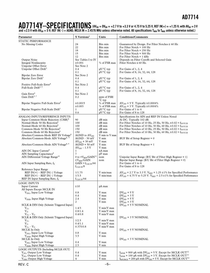
Parameter Y Versions1 Units Conditions/Comments
STATIC PERFORMANCENo Missing Codes 24 Bits min Guaranteed by Design. For Filter Notches ≤ 60 Hz
22 Bits min For Filter Notch = 100 Hz18 Bits min For Filter Notch = 250 Hz15 Bits min For Filter Notch = 500 Hz12 Bits min For Filter Notch = 1 kHz
Output Noise See Tables I to IV Depends on Filter Cutoffs and Selected GainIntegral Nonlinearity ±0.001 % of FSR max Filter Notches ≤ 60 Hz.Unipolar Offset Error See Note 2Unipolar Offset Drift3 0.4 µV/°C typ For Gains of 1, 2, 4
0.1 µV/°C typ For Gains of 8, 16, 32, 64, 128Bipolar Zero Error See Note 2Bipolar Zero Drift3 0.4 µV/°C typ For Gains of 1, 2, 4
0.1 µV/°C typ For Gains of 8, 16, 32, 64, 128Positive Full-Scale Error4 See Note 2Full-Scale Drift3, 5 0.4 µV/°C typ For Gains of 1, 2, 4
0.1 µV/°C typ For Gains of 8, 16, 32, 64, 128Gain Error6 See Note 2Gain Drift3, 7 0.2 ppm of FSR/
°C typBipolar Negative Full-Scale Error2 ±0.0015 % of FSR max AVDD = 5 V. Typically ±0.0004%
±0.003 % of FSR max AVDD = 3 V. Typically ±0.0004%Bipolar Negative Full-Scale Drift3 1 µV/°C typ For Gains of 1 to 4
0.6 µV/°C typ For Gains of 8 to 128
ANALOG INPUTS/REFERENCE INPUTS Specifications for AIN and REF IN Unless NotedInput Common-Mode Rejection (CMR)8 90 dB min At DC. Typically 102 dB.Normal-Mode 50 Hz Rejection8 100 dB min For Filter Notches of 10 Hz, 25 Hz, 50 Hz, ±0.02 × fNOTCH
Normal-Mode 60 Hz Rejection8 100 dB min For Filter Notches of 10 Hz, 30 Hz, 60 Hz, ±0.02 × fNOTCH
Common-Mode 50 Hz Rejection8 150 dB min For Filter Notches of 10 Hz, 25 Hz, 50 Hz, ±0.02 × fNOTCH
Common-Mode 60 Hz Rejection8 150 dB min For Filter Notches of 10 Hz, 30 Hz, 60 Hz, ±0.02 × fNOTCH
Absolute/Common-Mode REF IN Voltage8 AGND to AVDD V min to V maxAbsolute/Common-Mode AIN Voltage8, 9 AGND – 30 mV V min BUF Bit of Setup Register = 0
AVDD + 30 mV V maxAbsolute/Common-Mode AIN Voltage8, 9 AGND + 50 mV V min BUF Bit of Setup Register = 1
AVDD – 1.5 V V maxAIN DC Input Current8 1 nA maxAIN Sampling Capacitance8 7 pF maxAIN Differential Voltage Range10 0 to +VREF/GAIN11 nom Unipolar Input Range (B/U Bit of Filter High Register = 1)
±VREF/GAIN nom Bipolar Input Range (B/U Bit of Filter High Register = 0)AIN Input Sampling Rate, fS GAIN × fCLK IN/64 For Gains of 1 to 4
fCLK IN/8 For Gains of 8 to 128Reference Input Range
REF IN(+) – REF IN(–) Voltage 1/1.75 V min/max AVDD = 2.7 V to 3.3 V. VREF = 1.25 ±1% for Specified PerformanceREF IN(+) – REF IN(–) Voltage 1/3.5 V min/max AVDD = 4.75 V to 5.25 V. VREF = 2.5 ±1% for Specified Performance
REF IN Input Sampling Rate, fS fCLK IN/64
LOGIC INPUTSInput Current ±10 µA maxAll Inputs Except MCLK IN
VINL, Input Low Voltage 0.8 V max DVDD = 5 V0.4 V max DVDD = 3 V
VINH, Input High Voltage 2.4 V min DVDD = 5 V2 V min DVDD = 3 V
SCLK & DIN Only (Schmitt Triggered Input) DVDD = 5 V NOMINALVT+ 1.4/3 V min/V maxVT– 0.8/1.4 V min/V maxVT+ – VT– 0.4/0.8 V min/V max
SCLK & DIN Only (Schmitt Triggered Input) DVDD = 3 V NOMINALVT+ 1/2.5 V min/V maxVT– 0.4/1.1 V min/V maxVT+ – VT– 0.375/0.8 V min/V max
MCLK In Only DVDD = 5 V NOMINALVINL, Input Low Voltage 0.8 V maxVINH, Input High Voltage 3.5 V min
MCLK In Only DVDD = 3 V NOMINALVINL, Input Low Voltage 0.4 V maxVINH, Input High Voltage 2.5 V min
LOGIC OUTPUTS (Including MCLK OUT)VOL, Output Low Voltage 0.4 V max ISINK = 800 µA with DVDD = 5 V. Except for MCLK OUT12
VOL, Output Low Voltage 0.4 V max ISINK = 100 µA with DVDD = 3 V. Except for MCLK OUT12
VOH, Output High Voltage 4 V min ISOURCE = 200 µA with DVDD = 5 V. Except for MCLK OUT12
AD7714Y–SPECIFICATIONS (AVDD = DVDD = +2.7 V to +3.3 V or 4.75 V to 5.25 V, REF IN(+) = +1.25 V; with AVDD = 3 Vand +2.5 V with AVDD = 5 V; REF IN(–) = AGND; MCLK IN = 2.4576 MHz unless otherwise noted. All specifications TMIN to TMAX unless otherwise noted.)
AD7714
REV. C –5–

Parameter Y Versions Units Conditions/Comments
LOGIC OUTPUTS (Continued))VOH, Output High Voltage DVDD – 0.6 V min ISOURCE = 100 µA with DVDD = 3 V. Except for MCLK OUT12
Floating State Leakage Current ±10 µA maxFloating State Output Capacitance13 9 pF typData Output Coding Binary Unipolar Mode
Offset Binary Bipolar Mode
TRANSDUCER BURNOUT14
Current 1 µA nomInitial Tolerance ±10 % typDrift 0.1 %/°C typ
SYSTEM CALIBRATIONPositive Full-Scale Calibration Limit15 (1.05 × VREF)/GAIN V max GAIN Is the Selected PGA Gain (Between 1 and 128)Negative Full-Scale Calibration Limit15 –(1.05 × VREF)/GAIN V max GAIN Is the Selected PGA Gain (Between 1 and 128)Offset Calibration Limit16 –(1.05 × VREF)/GAIN V max GAIN Is the Selected PGA Gain (Between 1 and 128)Input Span16 0.8 × VREF/GAIN V min GAIN Is the Selected PGA Gain (Between 1 and 128)
(2.1 × VREF)/GAIN V max GAIN Is the Selected PGA Gain (Between 1 and 128)
POWER REQUIREMENTSPower Supply Voltages
AVDD Voltage +2.7 to +3.3 or V+4.75 to +5.25 V For Specified Performance
DVDD Voltage +2.7 to +5.25 V For Specified PerformancePower Supply Currents
AVDD Current AVDD = 3 V or 5 V. BST Bit of Filter High Register = 017, CLKDIS = 10.28 mA max Typically 0.22 mA. BUFFER = 0 V. fCLK IN = 1 MHz or 2.4576 MHz0.6 mA max Typically 0.45 mA. BUFFER = DVDD. fCLK IN = 1 MHz or 2.4576 MHz
AVDD = 3 V or 5 V. BST Bit of Filter High Register = 117
0.5 mA max Typically 0.38 mA. BUFFER = 0 V. fCLK IN = 2.4576 MHz1.1 mA max Typically 0.8 mA. BUFFER = DVDD. fCLK IN = 2.4576 MHz
DVDD Current18 Digital I/Ps = 0 V or DVDD. External MCLK IN, CLKDIS = 10.080 mA max Typically 0.06 mA. DVDD = 3 V. fCLK IN = 1 MHz0.16 mA max Typically 0.13 mA. DVDD = 5 V. fCLK IN = 1 MHz0.18 mA max Typically 0.15 mA. DVDD = 3 V. fCLK IN = 2.4576 MHz0.35 mA max Typically 0.3 mA. DVDD = 5 V. fCLK IN = 2.4576 MHz
Power Supply Rejection19 See Note 20 dB typNormal-Mode Power Dissipation18 AVDD = DVDD = +3 V. Digital I/Ps = 0 V or DVDD. External MCLK IN
BST Bit of Filter High Register = 017
1.05 mW max Typically 0.84 mW. BUFFER = 0 V. fCLK IN = 1 MHz. BST Bit = 02.04 mW max Typically 1.53 mW. BUFFER = +3 V. fCLK IN = 1 MHz. BST Bit = 01.35 mW max Typically 1.11 mW. BUFFER = 0 V. fCLK IN = 2.4576 MHz. BST Bit = 02.34 mW max Typically 1.9 mW. BUFFER = +3 V. fCLK IN = 2.4576 MHz. BST Bit = 0
Normal-Mode Power Dissipation AVDD = DVDD = +5 V. Digital I/Ps = 0 V or DVDD. External MCLK IN2.1 mW max Typically 1.75 mW. BUFFER = 0 V. fCLK IN = 1 MHz. BST Bit = 03.75 mW max Typically 2.9 mW. BUFFER = +5 V. fCLK IN = 1 MHz. BST Bit = 03.1 mW max Typically 2.6 mW. BUFFER = 0 V. fCLK IN = 2.4576 MHz. BST Bit = 04.75 mW max Typically 3.75 mW. BUFFER = +5 V. fCLK IN = 2.4576 MHz. BST Bit = 0
Standby (Power-Down) Current21 18 µA max External MCLK IN = 0 V or DVDD. Typically 9 µA. VDD = +5 VStandby (Power-Down) Current21 10 µA max External MCLK IN = 0 V or DVDD. Typically 4 µA. VDD = +3 V
NOTES1Temperature range is as follows: Y Version: –40°C to +105°C.2A calibration is effectively a conversion so these errors will be of the order of the conversion noise shown in Tables I to IV. This applies after calibration at the temperature of interest.3Recalibration at any temperature will remove these drift errors.4Positive Full-Scale Error includes Zero-Scale Errors (Unipolar Offset Error or Bipolar Zero Error) and applies to both unipolar and bipolar input ranges.5Full-Scale Drift includes Zero-Scale Drift (Unipolar Offset Drift or Bipolar Zero Drift) and applies to both unipolar and bipolar input ranges.6Gain Error does not include Zero-Scale Errors. It is calculated as Full-Scale Error—Unipolar Offset Error for unipolar ranges and Full-Scale Error—Bipolar Zero Error for
bipolar ranges.7Gain Error Drift does not include Unipolar Offset Drift/Bipolar Zero Drift. It is effectively the drift of the part if zero-scale calibrations only were performed as is the case with background calibration.8These numbers are guaranteed by design and/or characterization.9The common-mode voltage range on the input pairs applies provided the absolute input voltage specification is obeyed.
10The input voltage range on the analog inputs is given here with respect to the voltage on the respective negative input of its differential or pseudo-differential pair. See Table VII for whichinputs form differential pairs.
11VREF = REF IN(+) – REF IN(–).12These logic output levels apply to the MCLK OUT output only when it is loaded with a single CMOS load.13Sample tested at +25°C to ensure compliance.14See Burnout Current section.15After calibration, if the input voltage exceeds positive full scale, the converter will output all 1s. If the input is less than negative full scale, then the device outputs all 0s.16These calibration and span limits apply provided the absolute voltage on the analog inputs does not exceed AVDD + 30 mV or go more negative than AGND – 30 mV. The offset calibration
limit applies to both the unipolar zero point and the bipolar zero point.17For higher gains (≥8) at fCLK IN = 2.4576 MHz, the BST bit of the Filter High Register must be set to 1. For other conditions, it can be set to 0.18When using a crystal or ceramic resonator across the MCLK pins as the clock source for the device, the DVDD current and power dissipation will vary depending on the crystal or resonator
type (see Clocking and Oscillator Circuit section).19Measured at dc and applies in the selected passband. PSRR at 50 Hz will exceed 120 dB with filter notches of 5 Hz, 10 Hz, 25 Hz or 50 Hz. PSRR at 60 Hz will exceed 120 dB with filter
notches of 6 Hz, 10 Hz, 30 Hz or 60 Hz.20PSRR depends on gain.
Gain 1 2 4 8–128AVDD = 3 V 86 dB 78 dB 85 dB 93 dBAVDD = 5 V 90 dB 78 dB 84 dB 91 dB
21If the external master clock continues to run in standby mode, the standby current increases to 150 µA typical with 5 V supplies and 75 µA typical with 3.3 V supplies. When using a crystalor ceramic resonator across the MCLK pins as the clock source for the device, the internal oscillator continues to run in standby mode and the power dissipation depends on the crystal orresonator type (see Standby Mode section).
Specifications subject to change without notice.
AD7714Y
REV. C–6–

2
AD7714
REV. C –7–
ORDERING GUIDE
AVDD Temperature PackageModel Supply Range Option*
AD7714AN-5 5 V –40°C to +85°C N-24AD7714AR-5 5 V –40°C to +85°C R-24AD7714ARS-5 5 V –40°C to +85°C RS-28AD7714AN-3 3 V –40°C to +85°C N-24AD7714AR-3 3 V –40°C to +85°C R-24AD7714ARS-3 3 V –40°C to +85°C RS-28AD7714YN 3 V/5 V –40°C to +105°C N-24AD7714YR 3 V/5 V –40°C to +105°C R-24AD7714YRU 3 V/5 V –40°C to +105°C RU-24AD7714AChips-5 5 V –40°C to +85°C DieAD7714AChips-3 3 V –40°C to +85°C DieEVAL-AD7714-5EB 5 V Evaluation BoardEVAL-AD7714-3EB 3 V Evaluation Board
*N = Plastic DIP; R = SOIC; RS = SSOP; RU = Thin Shrink Small Outline.
TIMING CHARACTERISTICS1, 2 (AVDD = DVDD = +2.7 V to +5.25 V; AGND = DGND = 0 V; fCLKIN = 2.5 MHz; Input Logic 0 = 0 V,Logic 1 = DVDD unless otherwise noted.)
Limit at TMIN, TMAXParameter (A, Y Versions) Units Conditions/Comments
fCLKIN3, 4 400 kHz min Master Clock Frequency: Crystal/Resonator or Externally
Supplied2.5 MHz max For Specified Performance
tCLK IN LO 0.4 × tCLK IN ns min Master Clock Input Low Time. tCLK IN = 1/fCLK INtCLK IN HI 0.4 × tCLK IN ns min Master Clock Input High TimetDRDY 500 × tCLK IN ns nom DRDY High Timet1 100 ns min SYNC Pulsewidtht2 100 ns min RESET PulsewidthRead Operationt3 0 ns min DRDY to CS Setup Timet4 0 ns min CS Falling Edge to SCLK Active Edge Setup Time5
t56 0 ns min SCLK Active Edge to Data Valid Delay5
80 ns max DVDD = +5 V100 ns max DVDD = +3 V
t6 100 ns min SCLK High Pulsewidtht7 100 ns min SCLK Low Pulsewidtht8 0 ns min CS Rising Edge to SCLK Active Edge Hold Time5
t97 10 ns min Bus Relinquish Time after SCLK Active Edge5
60 ns max DVDD = +5 V100 ns max DVDD = +3 V
t10 100 ns max SCLK Active Edge to DRDY High5, 8
Write Operationt11 0 ns min CS Falling Edge to SCLK Active Edge Setup Time5
t12 30 ns min Data Valid to SCLK Edge Setup Timet13 20 ns min Data Valid to SCLK Edge Hold Timet14 100 ns min SCLK High Pulsewidtht15 100 ns min SCLK Low Pulsewidtht16 0 ns min CS Rising Edge to SCLK Edge Hold Time
NOTES1Sample tested at +25°C to ensure compliance. All input signals are specified with tr = tf = 5 ns (10% to 90% of DV DD) and timed from a voltage level of 1.6 V.2See Figures 6 and 7. Timing applies for all grades.3CLKIN Duty Cycle range is 45% to 55%. CLKIN must be supplied whenever the AD7714 is not in standby mode. If no clock is present in this case, the device candraw higher current than specified and possibly become uncalibrated.
4The AD7714 is production tested with fCLKIN at 2.4576 MHz (1 MHz for some IDD tests). It is guaranteed by characterization to operate at 400 kHz.5SCLK active edge is falling edge of SCLK with POL = 1; SCLK active edge is rising edge of SCLK with POL = 0.6These numbers are measured with the load circuit of Figure 1 and defined as the time required for the output to cross the V OL or VOH limits.7These numbers are derived from the measured time taken by the data output to change 0.5 V when loaded with the circuit of Figure 1. The measured number is thenextrapolated back to remove effects of charging or discharging the 100 pF capacitor. This means that the times quoted in the timing characteristics are the true busrelinquish times of the part and as such are independent of external bus loading capacitances.
8DRDY returns high after the first read from the device after an output update. The same data can be read again, if required, while DRDY is high although careshould be taken that subsequent reads do not occur close to the next output update.
Specifications subject to change without notice.
Figure 1. Load Circuit for Access Time and Bus Relinquish Time
TO OUTPUTPIN
50pF
ISINK (800mA AT DVDD = +5V 100mA AT DVDD = +3.3V)
+1.6V
ISOURCE (200mA AT DVDD = +5V 100mA AT DVDD = +3.3V)

AD7714
REV. C–8–
DIP and SOIC/TSSOP
ABSOLUTE MAXIMUM RATINGS*(TA = +25°C unless otherwise noted)
AVDD to AGND . . . . . . . . . . . . . . . . . . . . . . . . –0.3 V to +7 VAVDD to DGND . . . . . . . . . . . . . . . . . . . . . . . . –0.3 V to +7 VDVDD to AGND . . . . . . . . . . . . . . . . . . . . . . . . –0.3 V to +7 VDVDD to DGND . . . . . . . . . . . . . . . . . . . . . . . . –0.3 V to +7 VAnalog Input Voltage to AGND . . . . . –0.3 V to AVDD + 0.3 VReference Input Voltage to AGND . . . –0.3 V to AVDD + 0.3 VDigital Input Voltage to DGND . . . . . –0.3 V to DVDD + 0.3 VDigital Output Voltage to DGND . . . . –0.3 V to DVDD + 0.3 VOperating Temperature Range
Commercial (A Version) . . . . . . . . . . . . . . . –40°C to +85°CExtended (Y Version) . . . . . . . . . . . . . . . . . –40°C to +105°C
Storage Temperature Range . . . . . . . . . . . . . –65°C to +150°CJunction Temperature . . . . . . . . . . . . . . . . . . . . . . . . . .+150°CPlastic DIP Package, Power Dissipation . . . . . . . . . . . 450 mW
θJA Thermal Impedance . . . . . . . . . . . . . . . . . . . . . 105°C/WLead Temperature (Soldering, 10 sec) . . . . . . . . . . . .+260°C
SOIC Package, Power Dissipation . . . . . . . . . . . . . . . . 450 mWθJA Thermal Impedance . . . . . . . . . . . . . . . . . . . . . . 75°C/WLead Temperature, Soldering
Vapor Phase (60 sec) . . . . . . . . . . . . . . . . . . . . . . +215°CInfrared (15 sec) . . . . . . . . . . . . . . . . . . . . . . . . . . +220°C
SSOP Package, Power Dissipation . . . . . . . . . . . . . . . . 450 mWθJA Thermal Impedance . . . . . . . . . . . . . . . . . . . . . 109°C/WLead Temperature, Soldering
Vapor Phase (60 sec) . . . . . . . . . . . . . . . . . . . . . . +215°CInfrared (15 sec) . . . . . . . . . . . . . . . . . . . . . . . . . . +220°C
TSSOP Package, Power Dissipation . . . . . . . . . . . . . . 450 mWθJA Thermal Impedance . . . . . . . . . . . . . . . . . . . . . 128°C/WLead Temperature, Soldering
Vapor Phase (60 sec) . . . . . . . . . . . . . . . . . . . . . . +215°CInfrared (15 sec) . . . . . . . . . . . . . . . . . . . . . . . . . . +220°C
*Stresses above those listed under Absolute Maximum Ratings may cause perma-nent damage to the device. This is a stress rating only; functional operation of thedevice at these or any other conditions above those listed in the operationalsections of this specification is not implied. Exposure to absolute maximum ratingconditions for extended periods may affect device reliability.
CAUTIONESD (electrostatic discharge) sensitive device. Electrostatic charges as high as 4000 V readilyaccumulate on the human body and test equipment and can discharge without detection.Although these devices feature proprietary ESD protection circuitry, permanent damage may stilloccur on these devices if they are subjected to high energy electrostatic discharges. Therefore,proper ESD precautions are recommended to avoid performance degradation or loss of functionality.
PIN CONFIGURATIONS
SSOP
SCLK
MCLK IN
DGND
DVDD
SYNC
AIN1
DRDY
CS
AGND
MCLK OUT
POL
DIN
DOUT
AIN2 AIN6
AIN3 AIN5
AIN4
STANDBY
AVDD
TOP VIEW(Not to Scale)
AD7714RESET
REF IN(+)
REF IN(–)
BUFFER
NC = NO CONNECT
SCLK
MCLK IN
DGND
DVDD
SYNC
RESET
NC
DRDY
CS
NC
MCLK OUT
POL
DIN
DOUT
NC NC
AIN1 AGND
AIN2 AIN6
AIN3 AIN5
AIN4 REF IN(+)
STANDBY REF IN(–)
AVDD BUFFER
TOP VIEW(Not to Scale)
AD7714
WARNING!
ESD SENSITIVE DEVICE

2
AD7714
REV. C –9–
PIN FUNCTION DESCRIPTION
DIP/SOIC PIN NUMBERS
PinNo. Mnemonic Function
1 SCLK Serial Clock. Logic Input. An external serial clock is applied to this input to access serial data from theAD7714. This serial clock can be a continuous clock with all data transmitted in a continuous train of pulses.Alternatively, it can be a noncontinuous clock with the information being transmitted to the AD7714 in smallerbatches of data.
2 MCLK IN Master Clock signal for the device. This can be provided in the form of a crystal/resonator or external clock. Acrystal/resonator can be tied across the MCLK IN and MCLK OUT pins. Alternatively, the MCLK IN pin canbe driven with a CMOS-compatible clock and MCLK OUT left unconnected. The part is specified with clockinput frequencies of both 1 MHz and 2.4576 MHz.
3 MCLK OUT When the master clock for the device is a crystal/resonator, the crystal/resonator is connected between MCLKIN and MCLK OUT. If an external clock is applied to the MCLK IN, MCLK OUT provides an inverted clocksignal. This clock can be used to provide a clock source for external circuits.
4 POL Clock Polarity. Logic Input. With this input low, the first transition of the serial clock in a data transferoperation is from a low to a high. In microcontroller applications, this means that the serial clock should idlelow between data transfers. With this input high, the first transition of the serial clock in a data transferoperation is from a high to a low. In microcontroller applications, this means that the serial clock should idlehigh between data transfers.
5 SYNC Logic Input which allows for synchronization of the digital filters and analog modulators when using a numberof AD7714s. While SYNC is low, the nodes of the digital filter, the filter control logic and the calibrationcontrol logic are reset and the analog modulator is also held in its reset state. SYNC does not affect the digitalinterface and does not reset DRDY if it is low.
6 RESET Logic Input. Active low input which resets the control logic, interface logic, digital filter and analog modulatorof the part to power-on status.
7 AIN1 Analog Input Channel 1. Programmable-gain analog input which can be used as a pseudo-differential inputwhen used with AIN6 or as the positive input of a differential analog input pair when used with AIN2 (seeCommunications Register section).
8 AIN2 Analog Input Channel 2. Programmable-gain analog input which can be used as a pseudo-differential inputwhen used with AIN6 or as the negative input of a differential analog input pair when used with AIN1 (seeCommunications Register section).
9 AIN3 Analog Input Channel 3. Programmable-gain analog input which can be used as a pseudo-differential inputwhen used with AIN6 or as the positive input of a differential analog input pair when used with AIN4 (seeCommunications Register section).
10 AIN4 Analog Input Channel 4. Programmable-gain analog input which can be used as a pseudo-differential inputwhen used with AIN6 or as the negative input of a differential analog input pair when used with AIN3 (seeCommunications Register section).
11 STANDBY Logic Input. Taking this pin low shuts down the analog and digital circuitry, reducing current consumption totypically 5 µA.
12 AVDD Analog Positive Supply Voltage, A Grade Versions: +3.3 V nominal (AD7714-3) or +5 V nominal (AD7714-5);Y Grade Versions: 3 V or 5 V nominal.
13 BUFFER Buffer Option Select. Logic Input. With this input low, the on-chip buffer on the analog input (after themultiplexer and before the analog modulator) is shorted out. With the buffer shorted out the current flowing inthe AVDD line is reduced to 270 µA. With this input high, the on-chip buffer is in series with the analog inputallowing the inputs to handle higher source impedances.
14 REF IN(–) Reference Input. Negative input of the differential reference input to the AD7714. The REF IN(–) can lieanywhere between AVDD and AGND provided REF IN(+) is greater than REF IN(–).
15 REF IN(+) Reference Input. Positive input of the differential reference input to the AD7714. The reference input isdifferential with the provision that REF IN(+) must be greater than REF IN(–). REF IN(+) can lie anywherebetween AVDD and AGND.
16 AIN5 Analog Input Channel 5. Programmable-gain analog input which is the positive input of a differential analoginput pair when used with AIN6 (see Communications Register section).
17 AIN6 Analog Input Channel 6. Reference point for AIN1 through AIN4 in pseudo-differential mode or as thenegative input of a differential input pair when used with AIN5 (see Communications Register section).
18 AGND Ground reference point for analog circuitry.

AD7714
REV. C–10–
PIN FUNCTION DESCRIPTION (Continued)
PinNo. Mnemonic Function
19 CS Chip Select. Active low Logic Input used to select the AD7714. With this input hard-wired low, the AD7714can operate in its three-wire interface mode with SCLK, DIN and DOUT used to interface to the device. CScan be used to select the device in systems with more than one device on the serial bus or as a framesynchronization signal in communicating with the AD7714.
20 DRDY Logic output. A logic low on this output indicates that a new output word is available from the AD7714 dataregister. The DRDY pin will return high upon completion of a read operation of a full output word. If no dataread has taken place, after an output update, the DRDY line will return high for 500 × tCLK IN cycles prior tothe next output update. This gives an indication of when a read operation should not be attempted to avoidreading from the data register as it is being updated. DRDY is also used to indicate when the AD7714 hascompleted its on-chip calibration sequence.
21 DOUT Serial Data Output with serial data being read from the output shift register on the part. This output shiftregister can contain information from the calibration registers, mode register, communications register, filterselection registers or data register depending on the register selection bits of the Communications Register.
22 DIN Serial Data Input with serial data being written to the input shift register on the part. Data from this input shiftregister is transferred to the calibration registers, mode register, communications register or filter selectionregisters depending on the register selection bits of the Communications Register.
23 DVDD Digital Supply Voltage, A Grade Versions: +3.3 V or +5 V nominal; Y Grade Versions: 3 V or 5 V nominal.24 DGND Ground reference point for digital circuitry.
BIPOLAR NEGATIVE FULL-SCALE ERRORThis is the deviation of the first code transition from the idealAIN(+) voltage (AIN(–) – VREF/GAIN + 0.5 LSB) when operat-ing in the bipolar mode.
POSITIVE FULL-SCALE OVERRANGEPositive Full-Scale Overrange is the amount of overhead avail-able to handle input voltages on AIN(+) input greater thanAIN(–) + VREF/GAIN (for example, noise peaks or excess volt-ages due to system gain errors in system calibration routines)without introducing errors due to overloading the analog modu-lator or overflowing the digital filter.
NEGATIVE FULL-SCALE OVERRANGEThis is the amount of overhead available to handle voltages onAIN(+) below AIN(–) – VREF/GAIN without overloading theanalog modulator or overflowing the digital filter. Note that theanalog input will accept negative voltage peaks even in the uni-polar mode provided that AIN(+) is greater than AIN(–) andgreater than AGND – 30 mV.
OFFSET CALIBRATION RANGEIn the system calibration modes, the AD7714 calibrates itsoffset with respect to the analog input. The Offset CalibrationRange specification defines the range of voltages that theAD7714 can accept and still calibrate offset accurately.
FULL-SCALE CALIBRATION RANGEThis is the range of voltages that the AD7714 can accept in thesystem calibration mode and still calibrate full scale correctly.
INPUT SPANIn system calibration schemes, two voltages applied in sequenceto the AD7714’s analog input define the analog input range.The input span specification defines the minimum and maxi-mum input voltages from zero to full scale that the AD7714 canaccept and still calibrate gain accurately.
TERMINOLOGY*INTEGRAL NONLINEARITYThis is the maximum deviation of any code from a straight linepassing through the endpoints of the transfer function. The end-points of the transfer function are zero scale (not to be confusedwith bipolar zero), a point 0.5 LSB below the first code transi-tion (000 . . . 000 to 000 . . . 001) and full scale, a point0.5 LSB above the last code transition (111 . . . 110 to111 . . . 111). The error is expressed as a percentage of fullscale.
POSITIVE FULL-SCALE ERRORPositive Full-Scale Error is the deviation of the last code transi-tion (111 . . . 110 to 111 . . . 111) from the ideal AIN(+) voltage(AIN(–) + VREF/GAIN – 3/2 LSBs). It applies to both unipolarand bipolar analog input ranges.
UNIPOLAR OFFSET ERRORUnipolar Offset Error is the deviation of the first code transitionfrom the ideal AIN(+) voltage (AIN(–) + 0.5 LSB) when oper-ating in the unipolar mode.
BIPOLAR ZERO ERRORThis is the deviation of the midscale transition (0111 . . . 111to 1000 . . . 000) from the ideal AIN(+) voltage (AIN(–) –0.5 LSB) when operating in the bipolar mode.
GAIN ERRORThis is a measure of the span error of the ADC. It includes full-scale errors but not zero-scale errors. For unipolar input rangesit is defined as (full-scale error – unipolar offset error) while forbipolar input ranges it is defined as (full-scale error – bipolarzero error).
*AIN(–) refers to the negative input of the differential input pairs or to AIN6when referring to the pseudo-differential input configurations.

2
AD7714
REV. C –11–
AD7714-5 OUTPUT NOISETable Ia shows the output rms noise and effective resolution for some typical notch and –3 dB frequencies for the AD7714-5 withfCLK IN = 2.4576 MHz while Table Ib gives the information for fCLK IN = 1 MHz. The numbers given are for the bipolar input rangeswith a VREF of +2.5 V and with BUFFER = 0. These numbers are typical and are generated at an analog input voltage of 0 V. Thenumbers in brackets in each table are for the effective resolution of the part (rounded to the nearest 0.5 LSB). The effective resolu-tion of the device is defined as the ratio of the output rms noise to the input full scale (i.e., 2 × VREF/GAIN). It should be noted thatit is not calculated using peak-to-peak output noise numbers. Peak-to-peak noise numbers can be up to 6.6 times the rms numberswhile effective resolution numbers based on peak-to-peak noise can be 2.5 bits below the effective resolution based on rms noise asquoted in the tables.
The output noise from the part comes from two sources. The first is the electrical noise in the semiconductor devices used in theimplementation of the modulator (device noise). Secondly, when the analog input signal is converted into the digital domain, quan-tization noise is added. The device noise is at a low level and is largely independent of frequency. The quantization noise starts atan even lower level but rises rapidly with increasing frequency to become the dominant noise source. Consequently, lower filternotch settings (below 100 Hz approximately for fCLK IN = 2.4576 MHz and below 40 Hz approximately for fCLK IN = 1 MHz) tend tobe device noise dominated while higher notch settings are dominated by quantization noise. Changing the filter notch and cutofffrequency in the quantization-noise dominated region results in a more dramatic improvement in noise performance than it does inthe device-noise dominated region as shown in Table I. Furthermore, quantization noise is added after the PGA, so effective resolu-tion is largely independent of gain for the higher filter notch frequencies. Meanwhile, device noise is added in the PGA and, there-fore, effective resolution reduces at high gains for lower notch frequencies. Additionally, in the device-noise dominated region, theoutput noise (in µV) is largely independent of reference voltage while in the quantization-noise dominated region, the noise is pro-portional to the value of the reference. It is possible to do post-filtering on the device to improve the output data rate for a given–3 dB frequency and also to further reduce the output noise.
At the lower filter notch settings (below 60 Hz for fCLK IN = 2.4576 MHz and below 25 Hz for fCLK IN = 1 MHz), the no missingcodes performance of the device is at the 24-bit level. At the higher settings, more codes will be missed until at 1 kHz notch settingfor fCLK IN = 2.4576 MHz (400 Hz for fCLK IN = 1 MHz), no missing codes performance is only guaranteed to the 12-bit level.
Table Ia. AD7714-5 Output Noise/Resolution vs. Gain and First Notch for f CLK IN = 2.4576 MHz, BUFFER = 0
Filter First Typical Output RMS Noise in mV (Effective Resolution in Bits)Notch & O/P –3 dB Gain of Gain of Gain of Gain of Gain of Gain of Gain of Gain ofData Rate Frequency 1 2 4 8 16 32 64 128
5 Hz 1.31 Hz 0.87 (22.5) 0.48 (22.5) 0.24 (22.5) 0.2 (21.5) 0.18 (20.5) 0.17 (20) 0.17 (19) 0.17 (18)10 Hz 2.62 Hz 1.0 (22.5) 0.78 (21.5) 0.48 (21.5) 0.33 (21) 0.25 (20.5) 0.25 (19.5) 0.25 (18.5) 0.25 (17.5)25 Hz 6.55 Hz 1.8 (21.5) 1.1 (21) 0.63 (21) 0.5 (20) 0.44 (19.5) 0.41 (18.5) 0.38 (17.5) 0.38 (16.5)30 Hz 7.86 Hz 2.5 (21) 1.31 (21) 0.84 (20.5) 0.57 (20) 0.46 (19.5) 0.43 (18.5) 0.4 (17.5) 0.4 (16.5)50 Hz 13.1 Hz 4.33 (20) 2.06 (20) 1.2 (20) 0.64 (20) 0.54 (19) 0.46 (18.5) 0.46 (17.5) 0.46 (16.5)60 Hz 15.72 Hz 5.28 (20) 2.36 (20) 1.33 (20) 0.87 (19.5) 0.63 (19) 0.62 (18) 0.6 (17) 0.56 (16)100 Hz 26.2 Hz 12.1 (18.5) 5.9 (18.5) 2.86 (19) 1.91 (18.5) 1.06 (18) 0.83 (17.5) 0.82 (16.5) 0.76 (15.5)250 Hz 65.5 Hz 127 (15.5) 58 (15.5) 29 (15.5) 15.9 (15.5) 6.7 (15.5) 3.72 (15.5) 1.96 (15.5) 1.5 (14.5)500 Hz 131 Hz 533 (13) 267 (13) 137 (13) 66 (13) 38 (13) 20 (13) 8.6 (13) 4.4 (13)1 kHz 262 Hz 2,850 (11) 1,258 (11) 680 (11) 297 (11) 131 (11) 99 (10.5) 53 (10.5) 28 (10.5)
Table Ib. AD7714-5 Output Noise/Resolution vs. Gain and First Notch for fCLK IN = 1 MHz, BUFFER = 0
Filter First Typical Output RMS Noise in mV (Effective Resolution in Bits)Notch & O/P –3 dB Gain of Gain of Gain of Gain of Gain of Gain of Gain of Gain ofData Rate Frequency 1 2 4 8 16 32 64 128
2 Hz 0.52 Hz 0.75 (22.5) 0.56 (22) 0.31 (22) 0.19 (21.5) 0.17 (21) 0.14 (20) 0.14 (19) 0.14 (18)4 Hz 1.05 Hz 1.04 (22) 0.88 (21.5) 0.45 (21.5) 0.28 (21) 0.21 (20.5) 0.21 (19.5) 0.21 (18.5) 0.21 (17.5)10 Hz 2.62 Hz 1.66 (21.5) 1.01 (21.5) 0.77 (20.5) 0.41 (20.5) 0.37 (19.5) 0.35 (19) 0.35 (18) 0.35 (17)25 Hz 6.55 Hz 5.2 (20) 2.06 (20) 1.4 (20) 0.86 (19.5) 0.63 (19) 0.61 (18) 0.59 (17) 0.59 (16)30 Hz 7.86 Hz 7.1 (19.5) 3.28 (19.5) 1.42 (19.5) 1.07 (19) 0.78 (18.5) 0.64 (18) 0.61 (17) 0.61 (16)50 Hz 13.1 Hz 19.4 (18) 9.11 (18) 4.2 (18) 2.45 (18) 1.56 (17.5) 1.1 (17) 0.82 (16.5) 0.8 (15.5)60 Hz 15.72 Hz 25 (17.5) 16 (17.5) 6.5 (17.5) 2.9 (17.5) 1.93 (17.5) 1.4 (17) 1.1 (16) 0.98 (15.5)100 Hz 26.2 Hz 102 (15.5) 58 (15.5) 25 (15.5) 13.5 (15.5) 5.7 (15.5) 3.9 (15.5) 2.1 (15) 1.3 (15)200 Hz 52.4 Hz 637 (13) 259 (13) 130 (13) 76 (13) 33 (13) 16 (13) 11 (13) 6 (12.5)400 Hz 104.8 Hz 2,830 (11) 1,430 (11) 720 (11) 334 (11) 220 (10.5) 94 (10.5) 54 (10.5) 25 (10.5)

AD7714
REV. C–12–
AD7714-3 OUTPUT NOISETable IIa shows the output rms noise and effective resolution for some typical notch and –3 dB frequencies for the AD7714-3 withfCLK IN = 2.4576 MHz while Table IIb gives the information for fCLK IN = 1 MHz. The numbers given are for the bipolar inputranges with a VREF of +1.25 V and BUFFER = 0. These numbers are typical and are generated at an analog input voltage of 0 V.The numbers in brackets in each table are for the effective resolution of the part (rounded to the nearest 0.5 LSB). The effectiveresolution of the device is defined as the ratio of the output rms noise to the input full scale (i.e., 2 × VREF/GAIN). It should benoted that it is not calculated using peak-to-peak output noise numbers. Peak-to-peak noise numbers can be up to 6.6 times the rmsnumbers while effective resolution numbers based on peak-to-peak noise can be 2.5 bits below the effective resolution based on rmsnoise as quoted in the tables.
The output noise from the part comes from two sources. The first is the electrical noise in the semiconductor devices used in theimplementation of the modulator (device noise). Secondly, when the analog input signal is converted into the digital domain, quan-tization noise is added. The device noise is at a low level and is largely independent of frequency. The quantization noise starts atan even lower level but rises rapidly with increasing frequency to become the dominant noise source. Consequently, lower filternotch settings (below 100 Hz approximately for fCLK IN = 2.4576 MHz and below 40 Hz approximately for fCLK IN = 1 MHz) tend tobe device noise dominated while higher notch settings are dominated by quantization noise. Changing the filter notch and cutofffrequency in the quantization noise dominated region results in a more dramatic improvement in noise performance than it does inthe device-noise dominated region as shown in Table II. Furthermore, quantization noise is added after the PGA, so effective reso-lution is largely independent of gain for the higher filter notch frequencies. Meanwhile, device noise is added in the PGA and, there-fore, effective resolution suffers a little at high gains for lower notch frequencies. Additionally, in the device-noise dominated region,the output noise (in µV) is largely independent of reference voltage while in the quantization-noise dominated region, the noise isproportional to the value of the reference. It is possible to do post-filtering on the device to improve the output data rate for a given–3 dB frequency and also to further reduce the output noise.
At the lower filter notch settings (below 60 Hz for fCLK IN = 2.4576 MHz and below 25 Hz for fCLK IN = 1 MHz), the no missingcodes performance of the device is at the 24-bit level. At the higher settings, more codes will be missed until at 1 kHz notch settingfor fCLK IN = 2.4576 MHz (400 Hz for fCLK IN = 1 MHz), no missing codes performance is only guaranteed to the 12-bit level.
Filter First Typical Output RMS Noise in mV (Effective Resolution in Bits)Notch & O/P –3 dB Gain of Gain of Gain of Gain of Gain of Gain of Gain of Gain ofData Rate Frequency 1 2 4 8 16 32 64 128
2 Hz 0.52 Hz 0.86 (21.5) 0.58 (21) 0.32 (21) 0.21 (20.5) 0.2 (19.5) 0.2 (18.5) 0.2 (17.5) 0.2 (16.5)4 Hz 1.05 Hz 1.26 (21) 0.74 (20.5) 0.44 (20.5) 0.35 (20) 0.3 (19) 0.3 (18) 0.3 (17) 0.3 (16)10 Hz 2.62 Hz 1.68 (20.5) 1.33 (20) 0.73 (20) 0.5 (19) 0.49 (18.5) 0.49 (17.5) 0.48 (16.5) 0.47 (15.5)25 Hz 6.55 Hz 3.82 (19.5) 2.0 (19.5) 1.2 (19) 0.88 (18.5) 0.66 (18) 0.57 (17) 0.55 (16) 0.55 (15)30 Hz 7.86 Hz 4.88 (19) 2.1 (19) 1.3 (19) 0.93 (18.5) 0.82 (17.5) 0.69 (17) 0.68 (16) 0.66 (15)50 Hz 13.1 Hz 11 (18) 4.8 (18) 2.4 (18) 1.4 (18) 1.4 (17) 0.73 (16.5) 0.71 (15.5) 0.7 (15)60 Hz 15.72 Hz 14.7 (17.5) 7.5 (17.5) 3.8 (17.5) 2.6 (17) 1.5 (16.5) 0.95 (16.5) 0.88 (15) 0.9 (14.5)100 Hz 26.2 Hz 61 (15.5) 30 (15.5) 12 (15.5) 6.1 (15.5) 2.9 (15.5) 2.4 (15) 1.8 (14.5) 1.8 (13.5)200 Hz 52.4 Hz 275 (13) 130 (13) 65 (13) 33 (13) 17 (13) 11 (13) 6.3 (12.5) 3 (12.5)400 Hz 104.8 Hz 1435 (11) 720 (11) 362 (11) 175 (11) 110 (10.5) 51 (10.5) 31 (10.5) 12 (10.5)
Table IIa. AD7714-3 Output Noise/Resolution vs. Gain and First Notch for f CLK IN = 2.4576 MHz, BUFFER = 0
Filter First Typical Output RMS Noise in mV (Effective Resolution in Bits)Notch & O/P –3 dB Gain of Gain of Gain of Gain of Gain of Gain of Gain of Gain ofData Rate Frequency 1 2 4 8 16 32 64 128
5 Hz 1.31 Hz 1.07 (21) 0.68 (21) 0.29 (21) 0.24 (20) 0.22 (19.5) 0.22 (18.5) 0.22 (17.5) 0.22 (16.5)10 Hz 2.62 Hz 1.69 (20.5) 1.1 (20) 0.56 (20) 0.35 (19.5) 0.33 (19) 0.33 (18) 0.33 (17) 0.33 (16)25 Hz 6.55 Hz 3.03 (19.5) 1.7 (19.5) 0.89 (19.5) 0.55 (19) 0.49 (18.5) 0.46 (17.5) 0.46 (16.5) 0.45 (15.5)30 Hz 7.86 Hz 3.55 (19.5) 2.1 (19) 1.1 (19) 0.61 (18.5) 0.58 (18) 0.57 (17) 0.55 (16) 0.55 (15)50 Hz 13.1 Hz 4.72 (19) 2.3 (19) 1.5 (18.5) 0.84 (18.5) 0.7 (18) 0.68 (17) 0.67 (16) 0.66 (15)60 Hz 15.72 Hz 5.12 (19) 3.1 (18.5) 1.6 (18) 0.98 (18) 0.9 (17.5) 0.7 (17) 0.69 (16) 0.68 (15)100 Hz 26.2 Hz 9.68 (18) 5.6 (18) 2.4 (18) 1.3 (18) 1.1 (17) 0.95 (16.5) 0.88 (15.5) 0.9 (14.5)250 Hz 65.5 Hz 44 (16) 31 (15.5) 15 (15.5) 5.8 (15.5) 3.7 (15.5) 2.4 (15) 1.8 (14.5) 1.8 (13.5)500 Hz 131 Hz 304 (13) 129 (13) 76 (13) 33 (13) 20 (13) 11 (13) 6.3 (12.5) 3 (12.5)1 kHz 262 Hz 1410 (11) 715 (11) 350 (11) 177 (11) 101 (10.5) 51 (10.5) 31 (10.5) 12 (10.5)
Table IIb. AD7714-3 Output Noise/Resolution vs. Gain and First Notch for fCLK IN = 1 MHz, BUFFER = 0

2
AD7714
REV. C –13–
BUFFERED MODE NOISETable III shows the typical output rms noise and effective resolution for some typical notch and –3 dB frequencies for the AD7714-5 with fCLK IN = 2.4576 MHz and BUFFER = +5 V. Table IV gives the information for the AD7714-3 again with fCLK IN = 2.4576MHz and BUFFER = +5 V. The numbers given are for the bipolar input ranges and are generated with a differential analog inputvoltage of 0 V. For the AD7714-5, the VREF voltage is +2.5 V while for the AD7714 the VREF voltage is +1.25 V. The numbers inbrackets in each table are for the effective resolution of the part (rounded to the nearest 0.5 LSB). The effective resolution of thedevice is defined as the ratio of the output rms noise to the input full scale (i.e., 2 × VREF/GAIN). It should be noted that it is notcalculated using peak-to-peak output noise numbers. Peak-to-peak noise numbers can be up to 6.6 times the rms numbers whileeffective resolution numbers based on peak-to-peak noise can be 2.5 bits below the effective resolution based on rms noise as quotedin the tables.
Table III. AD7714-5 Buffered Mode Output Noise/Resolution for fCLK IN = 2.4576 MHz
Filter First Typical Output RMS Noise in mV (Effective Resolution in Bits)Notch & O/P –3 dB Gain of Gain of Gain of Gain of Gain of Gain of Gain of Gain ofData Rate Frequency 1 2 4 8 16 32 64 128
5 Hz 1.31 Hz 0.99 (22.5) 0.68 (22) 0.46 (21.5) 0.26 (21) 0.26 (20) 0.26 (19) 0.26 (18) 0.26 (17)10 Hz 2.62 Hz 1.5 (21.5) 0.95 (21.5) 0.63 (21) 0.41 (20.5) 0.39 (19.5) 0.36 (18.5) 0.36 (17.5) 0.36 (16.5)25 Hz 6.55 Hz 2.5 (21) 1.7 (20.5) 0.88 (20.5) 0.75 (19.5) 0.57 (19) 0.57 (18) 0.57 (17) 0.56 (16)30 Hz 7.86 Hz 2.9 (20.5) 1.8 (20.5) 1 (20) 0.87 (19.5) 0.75 (18.5) 0.72 (17.5) 0.72 (16.5) 0.71 (15.5)50 Hz 13.1 Hz 4.2 (20) 2.5 (20) 1.5 (19.5) 1.1 (19) 0.94 (18.5) 0.94 (17.5) 0.94 (16.5) 0.87 (15.5)60 Hz 15.72 Hz 6.1 (19.5) 2.9 (19.5) 2 (19.5) 1.2 (19) 1 (18.5) 0.97 (17.5) 0.95 (16.5) 0.94 (15.5)100 Hz 26.2 Hz 13.8 (18.5) 6.5 (18.5) 3.5 (18.5) 2.2 (18) 1.3 (18) 1.2 (17) 1.3 (16) 1.1 (15)250 Hz 65.5 Hz 87 (16) 56 (15.5) 25 (15.5) 11 (15.5) 5.7 (15.5) 3.6 (15.5) 2.4 (15) 2.1 (14)500 Hz 131 Hz 508 (13.5) 241 (13.5) 117 (13.5) 73 (13) 34 (13) 16 (13) 8.5 (13) 5.2 (13)1 kHz 262 Hz 2860 (11) 1700 (10.5) 745 (10.5) 480 (10.5) 197 (10.5) 94 (10.5) 53 (10.5) 23 (10.5)
Table IV. AD7714-3 Buffered Mode Output Noise/Resolution for fCLK IN = 2.4576 MHz
Filter First Typical Output RMS Noise in mV (Effective Resolution in Bits)Notch & O/P –3 dB Gain of Gain of Gain of Gain of Gain of Gain of Gain of Gain ofData Rate Frequency 1 2 4 8 16 32 64 128
5 Hz 1.31 Hz 1.16 (21) 0.76 (20.5) 0.34 (20) 0.29 (20) 0.29 (19) 0.28 (18) 0.26 (17) 0.26 (16)10 Hz 2.62 Hz 1.7 (20.5) 1 (20.5) 0.7 (20) 0.46 (19.5) 0.45 (18.5) 0.4 (17.5) 0.4 (16.5) 0.4 (15.5)25 Hz 6.55 Hz 3.5 (19.5) 1.8 (19.5) 1.1 (19) 0.74 (18.5) 0.63 (18) 0.6 (17) 0.6 (16) 0.6 (15)30 Hz 7.86 Hz 3.7 (19.5) 2.2 (19) 1.3 (19) 0.76 (18.5) 0.68 (18) 0.66 (17) 0.66 (16) 0.66 (15)50 Hz 13.1 Hz 4.5 (19) 3 (18.5) 1.7 (18.5) 1.0 (18) 0.92 (17.5) 0.9 (16.5) 0.89 (15.5) 0.89 (14.5)60 Hz 15.72 Hz 5.3 (19) 3.3 (18.5) 1.8 (18.5) 1.1 (18) 1 (17) 0.96 (16.5) 0.96 (15.5) 0.96 (14.5)100 Hz 26.2 Hz 10 (18) 4.9 (18) 3.1 (17.5) 1.5 (17.5) 1.2 (17) 1.2 (16) 1.2 (15) 1.2 (14)250 Hz 65.5 Hz 47 (15.5) 29 (15.5) 15 (15.5) 7.5 (15.5) 4.7 (15) 2.6 (15) 2.5 (14) 1.6 (13.5)500 Hz 131 Hz 300 (13.5) 171 (13) 74 (13) 35 (13) 21 (13) 8.6 (13) 5.6 (13) 3.1 (12.5)1 kHz 262 Hz 1722 (10.5) 735 (10.5) 380 (10.5) 230 (10.5) 93 (10.5) 55 (10.5) 30 (10.5) 12 (10.5)

AD7714
REV. C–14–
ON-CHIP REGISTERSThe AD7714 contains eight on-chip registers which can be accessed via the serial port of the part. The first of these is a Communica-tions Register which controls the channel selection, decides whether the next operation is a read or write operation and also decideswhich register the next read or write operation accesses. All communications to the part must start with a write operation to theCommunications Register. After power-on or RESET, the device expects a write to its Communications Register. The data writtento this register determines whether the next operation to the part is a read or a write operation and also determines to which registerthis read or write operation occurs. Therefore, write access to any of the other registers on the part starts with a write operation to theCommunications Register followed by a write to the selected register. A read operation from any other register on the part (includingthe output data register) starts with a write operation to the Communications Register followed by a read operation from the selectedregister. The communications register also controls channel selection and the DRDY status is also available by reading from theCommunications Register. The second register is a Mode Register which determines calibration mode and gain setting. The thirdregister is labelled the Filter High Register and this determines the word length, bipolar/unipolar operation and contains the upper 4bits of the filter selection word. The fourth register is labelled the Filter Low Register and contains the lower 8 bits of the filter selec-tion word. The fifth register is a Test Register which is accessed when testing the device. The sixth register is the Data Register fromwhich the output data from the part is accessed. The final registers allow access to the part’s calibration registers. The Zero ScaleCalibration Register allows access to the zero scale calibration coefficients for the selected input channel while the Full Scale Calibra-tion Register allows access to the full scale calibration coefficients for the selected input channel. The registers are discussed in moredetail in the following sections.
Communications Register (RS2-RS0 = 0, 0, 0)The Communications Register is an 8-bit register from which data can either be read or to which data can be written. All communi-cations to the part must start with a write operation to the Communications Register. The data written to the Communications Reg-ister determines whether the next operation is a read or write operation and to which register this operation takes place. Once thesubsequent read or write operation to the selected register is complete, the interface returns to where it expects a write operation tothe Communications Register. This is the default state of the interface, and on power-up or after a RESET, the AD7714 is in thisdefault state waiting for a write operation to the Communications Register. In situations where the interface sequence is lost, if awrite operation of sufficient duration (containing at least 32 serial clock cycles) takes place with DIN high, the AD7714 returns tothis default state. Table V outlines the bit designations for the Communications Register.
Table V. Communications Register
Table VI. Register Selection
0/DRDY RS2 RS1 RS0 R/W CH2 CH1 CH0
0/DRDY For a write operation, a 0 must be written to this bit so that the write operation to the Communications Registeractually takes place. If a 1 is written to this bit, the part will not clock on to subsequent bits in the register. It will stayat this bit location until a 0 is written to this bit. Once a 0 is written to this bit, the next 7 bits will be loaded to theCommunications Register. For a read operation, this bit provides the status of the DRDY flag from the part. Thestatus of this bit is the same as the DRDY output pin.
RS2–RS0 Register Selection Bits. RS2 is the MSB of the three selection bits. The three bits select to which one of eight on-chipregisters the next read or write operation takes place as shown in Table VI along with the register size.
RS2 RS1 RS0 Register Register Size0 0 0 Communications Register 8 Bits0 0 1 Mode Register 8 Bits0 1 0 Filter High Register 8 Bits0 1 1 Filter Low Register 8 Bits1 0 0 Test Register 8 Bits1 0 1 Data Register 16 Bits or 24 Bits1 1 0 Zero-Scale Calibration Register 24 Bits1 1 1 Full-Scale Calibration Register 24 Bits

2
AD7714
REV. C –15–
CH2 CH1 CH0 AIN(+) AIN(–) Type Calibration Register Pair
0 0 0 AIN1 AIN6 Pseudo Differential Register Pair 00 0 1 AIN2 AIN6 Pseudo Differential Register Pair 10 1 0 AIN3 AIN6 Pseudo Differential Register Pair 20 1 1 AIN4 AIN6 Pseudo Differential Register Pair 21 0 0 AIN1 AIN2 Fully Differential Register Pair 01 0 1 AIN3 AIN4 Fully Differential Register Pair 11 1 0 AIN5 AIN6 Fully Differential Register Pair 21 1 1 AIN6 AIN6 Test Mode Register Pair 2
Mode Register (RS2-RS0 = 0, 0, 1); Power On/Reset Status: 00 HexThe Mode Register is an eight bit register from which data can either be read or to which data can be written. Table VIII outlines thebit designations for the Mode Register.
Table VIII. Mode Register
MD2 MD1 MD0 G2 G1 G0 BO FSYNC
MD2 MD1 MD0 Operating Mode
0 0 0 Normal Mode; this is the normal mode of operation of the device whereby the device is performing nor-mal conversions. This is the default condition of these bits after Power-On or RESET.
0 0 1 Self-Calibration; this activates self-calibration on the channel selected by CH2, CH1 and CH0 of theCommunications Register. This is a one step calibration sequence and when complete the part returns toNormal Mode with MD2, MD1 and MD0 returning to 0, 0, 0. The DRDY output or bit goes high whencalibration is initiated and returns low when this self-calibration is complete and a new valid word isavailable in the data register. The zero-scale calibration is performed at the selected gain on internallyshorted (zeroed) inputs and the full-scale calibration is performed at the selected gain on an internally-generated VREF/Selected Gain.
0 1 0 Zero-Scale System Calibration; this activates zero scale system calibration on the channel selected byCH2, CH1 and CH0 of the Communications Register. Calibration is performed at the selected gain onthe input voltage provided at the analog input during this calibration sequence. This input voltage shouldremain stable for the duration of the calibration. The DRDY output or bit goes high when calibration isinitiated and returns low when this zero-scale calibration is complete and a new valid word is available inthe data register. At the end of the calibration, the part returns to Normal Mode with MD2, MD1 andMD0 returning to 0, 0, 0.
0 1 1 Full-Scale System Calibration; this activates full-scale system calibration on the selected input channel.Calibration is performed at the selected gain on the input voltage provided at the analog input during thiscalibration sequence. This input voltage should remain stable for the duration of the calibration. Onceagain, the DRDY output or bit goes high when calibration is initiated and returns low when this full-scalecalibration is complete and a new valid word is available in the data register. At the end of the calibration,the part returns to Normal Mode with MD2, MD1 and MD0 returning to 0, 0, 0.
Table VII. Channel Selection
CH2–CH0 Channel Select. These three bits select a channel either for conversion or for access to calibration coefficients asoutlined in Table VII. There are three pairs of calibration registers on the part. In fully differential mode, the parthas three input channels so each channel has its own pair of calibration registers. In pseudo-differential mode, theAD7714 has five input channels with some of the input channel combinations sharing calibration registers. WithCH2, CH1 and CH0 at a logic 1, the part looks at the AIN6 input internally shorted to itself. This can be used asa test method to evaluate the noise performance of the part with no external noise sources. In this mode, the AIN6input should be connected to an external voltage within the allowable common-mode range for the part. ThePower-On or RESET status of these bits is 1,0,0 selecting the differential pair AIN1 and AIN2.

AD7714
REV. C–16–
MD2 MD1 MD0 Operating Mode (continued)
1 0 0 System-Offset Calibration; this activates system-offset calibration on the channel selected by CH2, CH1and CH0 of the Communications Register. This is a one step calibration sequence and when completethe part returns to Normal Mode with MD2, MD1 and MD0 returning to 0, 0, 0. The DRDY outputor bit goes high when calibration is initiated and returns low when this system offset calibration is com-plete and a new valid word is available in the data register. For this calibration type, the zero-scale cali-bration is performed at the selected gain on the input voltage provided at the analog input during thiscalibration sequence. This input voltage should remain stable for the duration of the calibration. Thefull-scale calibration is performed at the selected gain on an internally generated VREF/Selected Gain.
1 0 1 Background Calibration; this activates background calibration on the channel selected by CH2, CH1and CH0 of the Communications Register. If the background calibration mode is on, then the AD7714provides continuous self-calibration of the shorted (zeroed) inputs. This calibration takes place as partof the conversion sequence, extending the conversion time and reducing the word rate by a factor of six.Its major advantage is that the user does not have to worry about recalibrating the offset of the devicewhen there is a change in the ambient temperature or supplies. In this mode, the zero-scale calibrationis performed at the selected gain on internally shorted (zeroed) inputs. The calibrations are interleavedwith normal conversions and the calibration registers of the device are automatically updated. Becausethe background calibration does not perform full-scale calibrations, a self-calibration should be per-formed before placing the part in the background calibration mode.
1 1 0 Zero-Scale Self-Calibration; this activates zero-scale self-calibration on the channel selected by CH2,CH1 and CH0 of the Communications Register. This zero-scale self-calibration is performed at theselected gain on internally shorted (zeroed) inputs. This is a one step calibration sequence and whencomplete the part returns to Normal Mode with MD2, MD1 and MD0 returning to 0, 0, 0. The DRDYoutput or bit goes high when calibration is initiated and returns low when this zero-scale self-calibrationis complete and a new valid word is available in the data register.
1 1 1 Full-Scale Self-Calibration; this activates full-scale self-calibration on the channel selected by CH2,CH1 and CH0 of the Communications Register. This full-scale self-calibration is performed at theselected gain on an internally-generated VREF/Selected Gain. This is a one step calibration sequence andwhen complete the part returns to Normal Mode with MD2, MD1 and MD0 returning to 0, 0, 0. TheDRDY output or bit goes high when calibration is initiated and returns low when this full-scale self-calibration is complete and a new valid word is available in the data register.
G2 G1 G0 Gain Setting
0 0 0 10 0 1 20 1 0 40 1 1 81 0 0 161 0 1 321 1 0 641 1 1 128
BO Burnout Current. A 0 in this bit turns off the on-chip burnout currents. This is the default (Power-Onor RESET) status of this bit. A 1 in this bit activates the burnout currents. When active, the burnoutcurrents connect to the selected analog input pair, one to the AIN(+) input and one to the AIN(–) input.
FSYNC Filter Synchronization. When this bit is high, the nodes of the digital filter, the filter control logic andthe calibration control logic are held in a reset state and the analog modulator is also held in its resetstate. When this bit goes low, the modulator and filter start to process data and a valid word is availablein 3 × 1/(output update rate), i.e., the settling time of the filter. This FSYNC bit does not affect thedigital interface and does not reset the DRDY output if it is low.

2
AD7714
REV. C –17–
Filter Registers. Power On/Reset Status: Filter High Register: 01 Hex. Filter Low Register: 40 Hex.There are two 8-bit Filter Registers on the AD7714 from which data can either be read or to which data can be written. Tables IXand X outline the bit designations for the Filter Registers.
Table IX. Filter High Register (RS2–RS0 = 0, 1, 0)
B/U WL BST ZERO FS11 FS10 FS9 FS8 A Versions
B/U WL BST CLKDIS FS11 FS10 FS9 FS8 Y Versions
Table X. Filter Low Register (RS2–RS0 = 0, 1, 1)
FS7 FS6 FS5 FS4 FS3 FS2 FS1 FS0 All Versions
B/U Bipolar/Unipolar Operation. A 0 in this bit selects Bipolar Operation. This is the default (Power-On or RESET)status of this bit. A 1 in this bit selects unipolar operation.
WL Word Length. A 0 in this bit selects 16-bit word length when reading from the data register (i.e., DRDY returnshigh after 16 serial clock cycles in the read operation). This is the default (Power-On or RESET) status of thisbit. A 1 in this bit selects 24-bit word length.
BST Current Boost. A 0 in this bit reduces the current taken by the analog front end. When the part is operated withfCLK IN = 1 MHz or at gains of 1 to 4 with fCLK IN = 2.4576 MHz, this bit should be 0 to reduce the currentdrawn from AVDD, although the device will operate just as well with this bit at a 1. When the AD7714 is oper-ated at gains of 8 to 128 with fCLK IN = 2.4576 MHz, this bit must be 1 to ensure correct operation of thedevice. The Power-On or RESET status of this bit is 0.
ZERO To ensure correct operation of the A Versions of the part, a 0 must be written to this bit.
CLKDIS Master Clock Disable Bit. A Logic 1 in this bit disables the master clock from appearing at the MCLKOUTpin. When disabled, the MCLKOUT pin is forced low. This feature allows the user the flexibility of using theMCLKOUT as a clock source for other devices in the system or for turning off the MCLKOUT as a powersaving feature. When using an external master clock or the MCLKIN pin, the AD7714 continues to have inter-nal clocks and will convert normally with its CLKDIS bit active. When using a crystal oscillator or ceramicresonator across the MCLK IN or MCLKOUT pins, the AD7714 clock is stopped and no conversions takeplace when the CLKDIS bit is active.
FS11–FS0 Filter Selection. The on-chip digital filter provides a Sinc3 (or (Sinx/x)3 ) filter response. The 12 bits of dataprogrammed into these bits determine the filter cut-off frequency, the position of the first notch of the filter andthe data rate for the part. In association with the gain selection, it also determines the output noise (and hencethe effective resolution) of the device.
The first notch of the filter occurs at a frequency determined by the relationship:
filter first notch frequency = (fCLK IN/128)/code
where code is the decimal equivalent of the code in bits FS0 to FS11 and is in the range 19 to 4,000. With thenominal fCLK IN of 2.4576 MHz, this results in a first notch frequency range from 4.8 Hz to 1.01 kHz. Toensure correct operation of the AD7714, the value of the code loaded to these bits must be within this range.Failure to do this will result in unspecified operation of the device.
Changing the filter notch frequency, as well as the selected gain, impacts resolution. Tables I through IV showthe effect of the filter notch frequency and gain on the effective resolution of the AD7714. The output data rate(or effective conversion time) for the device is equal to the frequency selected for the first notch of the filter. Forexample, if the first notch of the filter is selected at 50 Hz then a new word is available at a 50 Hz rate or every20 ms. If the first notch is at 1 kHz, a new word is available every 1 ms.
The settling time of the filter to a full-scale step input change is worst case 4 × 1/(output data rate). Forexample, with the first filter notch at 50 Hz, the settling time of the filter to a full-scale step input change is80 ms max. This settling time can be reduced to 3 × 1/(output data rate) by synchronizing the step inputchange to a reset of the digital filter. In other words, if the step input takes place with the SYNC input low orthe FSYNC bit high, the settling time will be 3 × 1/(output data rate) from when SYNC returns high orFSYNC returns low. If a change of channel takes place, the settling time is 3 × 1/(output data rate) regardless ofthe SYNC or FSYNC status as the part issues an internal SYNC command when requested to change channels.
The –3 dB frequency is determined by the programmed first notch frequency according to the relationship:
filter –3 dB frequency = 0.262 × filter first notch frequency.

AD7714
REV. C–18–
Test Register (RS2–RS0 = 1, 0, 0)The part contains a Test Register which is used in testing the device. The user is advised not to change the status of any of the bits in thisregister from the default (Power-On or RESET) status of all 0s as the part will be placed in one of its test modes and will not operate cor-rectly. If the part enters one of its test modes, exercising RESET will exit the part from the mode. An alternative scheme for getting thepart out of one of its test modes, is to reset the interface by writing 32 successive 1s to the part and then write all 0s to the Test Register.
Data Register (RS2–RS0 = 1, 0, 1)The Data Register on the part is a read-only register which contains the most up-to-date conversion result from the AD7714. Theregister can be programmed to be either 16-bits or 24-bits wide, determined by the status of the WL bit of the Mode Register. If theCommunications Register data sets up the part for a write operation to this register, a write operation must actually take place inorder to return the part to where it is expecting a write operation to the Communications Register (the default state of the interface).However, the 16 or 24 bits of data written to the part will be ignored by the AD7714.
Zero-Scale Calibration Register (RS2–RS0 = 1, 1, 0); Power On/Reset Status: 1F4000 HexThe AD7714 contains three zero-scale calibration registers, labelled Zero-Scale Calibration Register 0 to Zero Scale CalibrationRegister 2. The three registers are totally independent of each other such that in fully differential mode there is a zero-scale registerfor each of the input channels. Each of these registers is a 24-bit read/write register and, when writing to the registers, 24 bits must bewritten; otherwise no data will be transferred to the register. The register is used in conjunction with the associated full-scale calibra-tion register to form a register pair. These register pairs are associated with input channel pairs as outlined in Table VII.
While the part is set up to allow access to these registers over the digital interface, the part itself no longer has access to the registercoefficients to correctly scale the output data. As a result, there is a possibility that after accessing the calibration registers (either reador write operation) the first output data read from the part may contain incorrect data. In addition, a read or write operation to thecalibration register should not be attempted while a calibration is in progress. These eventualities can be avoided by taking either theSYNC input low or the FSYNC bit of the Mode Register high before the calibration register operation and taking them either high orlow respectively after the operation is complete.
Full-Scale Calibration Register (RS2–RS0 = 1, 1, 1); Power On/Reset Status: 5761AB HexThe AD7714 contains three full-scale calibration registers, labelled Full-Scale Calibration Register 0 to Full-Scale Calibration Regis-ter 2. The three registers are totally independent of each other such that in fully differential mode there is a full-scale register for eachof the input channels. Each of these registers is a 24-bit read/write register and, when writing to the registers, 24 bits must be written,otherwise no data will be transferred to the register. The register is used in conjunction with the associated zero-scale calibrationregister to form a register pair. These register pairs are associated with input channel pairs as outlined in Table VII.
While the part is set up to allow access to these registers over the digital interface, the part itself no longer has access to the coeffi-cients to correctly scale the output data. As a result, there is a possibility that after accessing the calibration registers (either read orwrite operation) the first output data read from the part may contain incorrect data. In addition, a read or write operation to thecalibration register should not be attempted while a calibration is in progress. These eventualities can be avoided by taking either theSYNC input low or the FSYNC bit of the Mode Register high before the calibration register operation and taking them either high orlow respectively after the operation is complete.
CALIBRATION OPERATIONSThe AD7714 contains a number of calibration options as outlined previously. Table XI summarizes the calibration types, the opera-tions involved and the duration of the operations. There are two methods of determining the end of calibration. The first is to moni-tor when DRDY returns low at the end of the sequence. DRDY not only indicates when the sequence is complete but also that thepart has a valid new sample in its data register. This valid new sample is the result of a normal conversion which follows the calibra-tion sequence. The second method of determining when calibration is complete is to monitor the MD2, MD1 and MD0 bits of theMode Register. When these bits return to 0, 0, 0 following a calibration command, it indicates that the calibration sequence is com-plete. This method does not give any indication of there being a valid new result in the data register. However, it gives an earlier indication that calibration is complete than DRDY. The time to when the Mode Bits (MD2, MD1 and MD0) return to 0, 0, 0 represents the duration of the calibration. The sequence to when DRDY goes low also includes a normal conversion and a pipelinedelay, tP (2000 × tCLK IN), to correctly scale the results of this first conversion. The time for both methods is given in the table.
Table XI. Calibration Operations
Calibration Type MD2, MD1, MD0 Calibration Sequence Duration to Mode Bits Duration to DRDY
Self Calibration 0, 0, 1 Internal ZS Cal @ Selected Gain + 6 × 1/Output Rate 9 × 1/Output Rate + tp
Internal FS Cal @ Selected GainZS System Calibration 0, 1, 0 ZS Cal on AIN @ Selected Gain 3 × 1/Output Rate 4 × 1/Output Rate + tP
FS System Calibration 0, 1, 1 FS Cal on AIN @ Selected Gain 3 × 1/Output Rate 4 × 1/Output Rate + tP
System-Offset Calibration 1, 0, 0 ZS Cal on AIN @ Selected Gain + 6 × 1/Output Rate 9 × 1/Output Rate + tP
Internal FS Cal @ Selected GainBackground Calibration 1, 0, 1 Internal ZS Cal @ Selected Gain + Bits Not Reset 6 × 1/Output Rate
Normal ConversionZS Self Calibration 1, 1, 0 Internal ZS Cal @ Selected Gain 3 × 1/Output Rate 6 × 1/Output Rate + tP
FS Self Calibration 1, 1, 1 Internal FS Cal @ Selected Gain 3 × 1/Output Rate 6 × 1/Output Rate + tP

2
AD7714
REV. C –19–
CIRCUIT DESCRIPTIONThe AD7714 is a sigma-delta A/D converter with on-chip digi-tal filtering, intended for the measurement of wide dynamicrange, low frequency signals such as those in weigh-scale, pres-sure transducer, industrial control or process control applica-tions. It contains a sigma-delta (or charge-balancing) ADC, acalibration microcontroller with on-chip static RAM, a clockoscillator, a digital filter and a bidirectional serial communica-tions port. The part consumes only 500 µA of power supplycurrent and features a standby mode which requires only 10 µA,making it ideal for battery-powered or loop-powered instru-ments. The part comes in two versions, the AD7714-5, which isspecified for operation from a nominal +5 V analog supply(AVDD), and the AD7714-3, which is specified for operationfrom a nominal +3.3 V analog supply. Both versions can beoperated with a digital supply (DVDD) voltage of either +3.3 Vor +5 V. AD7714Y grade parts operate with a nominal AVDD
of 3 V or 5 V and can be operated with a digital supply voltageof either 3 V or 5 V.
The part contains three programmable-gain fully differentialanalog input channels that can be reconfigured as five pseudo-differential inputs. The gain range on all channels is from 1 to128, allowing the part to accept unipolar signals of between0 mV to +20 mV and 0 V to +2.5 V. In bipolar mode, the parthandles genuine bipolar signals of ±20 mV and quasi-bipolarsignals up to ±2.5 V when the reference input voltage equals+2.5 V. With a reference voltage of +1.25 V, the input rangesare from 0 mV to +10 mV to 0 V to +1.25 V in unipolar mode,while in bipolar mode, the part handles genuine bipolar signalsof ±10 mV and quasi-bipolar signals up to ±1.25 V.
The part employs a sigma-delta conversion technique to realizeup to 24 bits of no missing codes performance. The sigma-delta
modulator converts the sampled input signal into a digital pulsetrain whose duty cycle contains the digital information. Theprogrammable gain function on the analog input is alsoincorporated in this sigma-delta modulator with the input sam-pling frequency of the modulator being modified to give thehigher gains. A sinc3 digital low-pass filter processes the outputof the sigma-delta modulator and updates the output register ata rate determined by the first notch frequency of this filter. Theoutput data can be read from the serial port randomly or peri-odically at any rate up to the output register update rate. Thefirst notch of this digital filter, its –3 dB frequency and its out-put rate can be programmed via the filter high and filter lowregisters. With a master clock frequency of 2.4576 MHz, theprogrammable range for this first notch frequency and outputrate is from 4.8 Hz to 1.01 kHz giving a programmable rangefor the –3 dB frequency of 1.26 Hz to 265 Hz.
The basic connection diagram for the part is shown in Figure 2.This shows both the AVDD and DVDD pins of the AD7714 beingdriven from the analog +3 V or +5 V supply. Some applicationswill have AVDD and DVDD driven from separate supplies. In theconnection diagram shown, the AD7714’s analog inputs areconfigured as three fully differential inputs. The part is set upfor unbuffered mode on the these analog inputs. An AD780,precision +2.5 V reference, provides the reference source for thepart. On the digital side, the part is configured for three-wireoperation with CS tied to DGND. A quartz crystal or ceramicresonator provides the master clock source for the part. It maybe necessary to connect capacitors on the crystal or resonator toensure that it does not oscillate at overtones of its fundamentaloperating frequency. The values of capacitors will vary depend-ing on the manufacturer’s specifications.
SCLK
MCLK IN
DGND
DVDD
SYNC
RESET
DRDY
CS
MCLK OUT
POL
DIN
DOUT
AIN1
AGND
AIN2
AIN6
AIN3
AIN5
AIN4
REF IN(+)
STANDBY
REF IN(–)
AVDD
BUFFER
AD7714
0.1mF 0.1mF10mF
ANALOGGROUND
DIFFERENTIALANALOG INPUT 3
DIFFERENTIALANALOG INPUT 2
DIFFERENTIALANALOG INPUT 1
DIGITALGROUND
0.1mF10mF
VOUT
VIN
GND
AD780
ANALOG+5V SUPPLY
ANALOG+5V SUPPLY
DATAREADY
RECEIVE(READ)
SERIALDATASERIALCLOCK
CRYSTAL ORCERAMICRESONATOR
+5V
Figure 2. Basic Connection Diagram

AD7714
REV. C–20–
ANALOG INPUTAnalog Input RangesThe AD7714 contains six analog input pins (labelled AIN1 toAIN6) which can be configured as either three fully differentialinput channels or five pseudo-differential input channels. BitsCH0, CH1 and CH2 of the Communications Register configurethe analog input arrangement and the channel selection is asoutlined previously in Table VII. The input pairs (either differ-ential or pseudo-differential) provide programmable-gain, inputchannels which can handle either unipolar or bipolar inputsignals. It should be noted that the bipolar input signals arereferenced to the respective AIN(–) input of the input pair.
In unbuffered mode, the common-mode range of these inputs isfrom AGND to AVDD provided that the absolute value of the analoginput voltage lies between AGND – 30 mV and AVDD + 30 mV.This means that in unbuffered mode the part can handle bothunipolar and bipolar input ranges for all gains. In bufferedmode, the analog inputs can handle much larger source imped-ances, but the absolute input voltage range is restricted to be-tween AGND + 50 mV to AVDD – 1.5 V which also placesrestrictions on the common-mode range. This means that inbuffered mode there are some restrictions on the allowable gainsfor bipolar input ranges. Care must be taken in setting up thecommon-mode voltage and input voltage range so that theabove limits are not exceeded, otherwise there will be a degrada-tion in linearity performance.
In unbuffered mode, the analog inputs look directly into the7 pF input sampling capacitor, CSAMP. The dc input leakagecurrent in this unbuffered mode is 1 nA maximum. As a result,the analog inputs see a dynamic load which is switched at theinput sample rate (see Figure 3). This sample rate depends onmaster clock frequency and selected gain. CSAMP is charged toAIN(+) and discharged to AIN(–) every input sample cycle.The effective on-resistance of the switch, RSW, is typically 7 kΩ.
CSAMP must be charged through RSW and through any externalsource impedances every input sample cycle. Therefore, in unbuf-fered mode, source impedances mean a longer charge time forCSAMP and this may result in gain errors on the part. Table XIIshows the allowable external resistance/capacitance values, forunbuffered mode, such that no gain error to the 16-bit level isintroduced on the part. Table XIII shows the allowable externalresistance/capacitance values, once again for unbuffered mode,such that no gain error to the 20-bit level is introduced.
Table XII. External R, C Combination for No 16-Bit GainError (Unbuffered Mode Only)
Gain External Capacitance (pF)
0 50 100 500 1000 5000
1 368 kΩ 90.6 kΩ 54.2 kΩ 14.6 kΩ 8.2 kΩ 2.2 kΩ2 177.2 kΩ 44.2 kΩ 26.4 kΩ 7.2 kΩ 4 kΩ 1.12 kΩ4 82.8 kΩ 21.2 kΩ 12.6 kΩ 3.4 kΩ 1.94 kΩ 540 Ω8–128 35.2 kΩ 9.6 kΩ 5.8 kΩ 1.58 kΩ 880 Ω 240 Ω
Table XIII. External R, C Combination for No 20-Bit GainError (Unbuffered Mode Only)
Gain External Capacitance (pF)
0 50 100 500 1000 5000
1 290 kΩ 69 kΩ 40.8 kΩ 10.4 kΩ 5.6 kΩ 1.4 kΩ2 141 kΩ 33.8 kΩ 20 kΩ 5 kΩ 2.8 kΩ 700 Ω4 63.6 kΩ 16 kΩ 9.6 kΩ 2.4 kΩ 1.34 kΩ 340 Ω8–128 26.8 kΩ 7.2 kΩ 4.4 kΩ 1.1 kΩ 600 Ω 160 Ω
In buffered mode, the analog inputs look into the high impedanceinputs stage of the on-chip buffer amplifier. CSAMP is charged viathis buffer amplifier such that source impedances do not affectthe charging of CSAMP. This buffer amplifier has an offset leak-age current of 1 nA. In this buffered mode, large source imped-ances result in a dc offset voltage developed across the sourceimpedance but not in a gain error.
Input Sample RateThe modulator sample frequency for the AD7714 remains atfCLK IN/128 (19.2 kHz @ fCLK IN = 2.4576 MHz) regardless ofthe selected gain. However, gains greater than 1 are achievedby a combination of multiple input samples per modulator cycleand a scaling of the ratio of reference capacitor to input capaci-tor. As a result of the multiple sampling, the input sample rateof the device varies with the selected gain (see Table XIV). Inbuffered mode, the input is buffered before the input samplingcapacitor. In unbuffered mode, where the analog input looksdirectly into the sampling capacitor, the effective input imped-ance is 1/CSAMP × fS where CSAMP is the input sampling capaci-tance and fS is the input sample rate.
RSW (7kV TYP) HIGHIMPEDANCE>1GV
CSAMP(7pF )
VBIAS
SWITCHING FREQUENCY DEPENDS ONfCLKIN AND SELECTED GAIN
AIN(+)
AIN(–)
Figure 3. Unbuffered Analog Input Structure

2
AD7714
REV. C –21–
Table XIV. Input Sampling Frequency vs. Gain
Gain Input Sampling Freq (fS)
1 fCLK IN/64 (38.4 kHz @ fCLK IN = 2.4576 MHz)2 2 × fCLK IN/64 (76.8 kHz @ fCLK IN = 2.4576 MHz)4 4 × fCLK IN/64 (153.6 kHz @ fCLK IN = 2.4576 MHz)8 8 × fCLK IN/64 (307.2 kHz @ fCLK IN = 2.4576 MHz)16 8 × fCLK IN/64 (307.2 kHz @ fCLK IN = 2.4576 MHz)32 8 × fCLK IN/64 (307.2 kHz @ fCLK IN = 2.4576 MHz)64 8 × fCLK IN/64 (307.2 kHz @ fCLK IN = 2.4576 MHz)128 8 × fCLK IN/64 (307.2 kHz @ fCLK IN = 2.4576 MHz)
Burnout CurrentThe AD7714 contains two 1 µA currents, one source currentfrom AVDD to AIN(+) and one sink from AIN(–) to AGND. Thecurrents are either both on or off depending on the BO bit of theMode Register. These currents can be used in checking that atransducer has not burned out nor gone open-circuit beforeattempting to take measurements on that channel. If the cur-rents are turned on, allowed flow in the transducer, a measure-ment of the input voltage on the analog input taken and thevoltage measured is full scale, it indicates that the transducer hasgone open-circuit; if the voltage measured is zero, it indicatesthat the transducer has gone short-circuit. For normal opera-tion, these burnout currents are turned off by writing a 0 to theBO bit. For the source current to work correctly, the appliedvoltage on AIN(+) should not go within 500 mV of AVDD. Forthe sink current to work correctly, the applied voltage on theAIN(–) input should not go within 500 mV of AGND.
Bipolar/Unipolar InputsThe analog inputs on the AD7714 can accept either unipolar orbipolar input voltage ranges. Bipolar input ranges do not implythat the part can handle negative voltages on its analog inputs,since the analog input cannot go more negative than –30 mV toensure correct operation of the part. The input channels areeither fully differential or pseudo-differential (all other channelsreferenced to AIN6). In either case, the input channels arearranged in pairs with an AIN(+) and AIN(–). As a result, thevoltage to which the unipolar and bipolar signals on the AIN(+)input are referenced is the voltage on the respective AIN(–)input. For example, if AIN(–) is +2.5 V and the AD7714 isconfigured for unipolar operation with a gain of 2 and a VREF of+2.5 V, the input voltage range on the AIN(+) input is +2.5 V to+3.75 V. If AIN(–) is +2.5 V and the AD7714 is configured forbipolar mode with a gain of 2 and a VREF of +2.5 V, the analoginput range on the AIN(+) input is +1.25 V to +3.75 V (i.e.,2.5 V ± 1.25 V). If AIN(–) is at AGND, the part cannot be con-figured for bipolar ranges in excess of ±30 mV.
Bipolar or unipolar options are chosen by programming the B/Ubit of the Filter High Register. This programs the selected chan-nel for either unipolar or bipolar operation. Programming thechannel for either unipolar or bipolar operation does not changeany of the input signal conditioning; it simply changes the dataoutput coding and the points on the transfer function wherecalibrations occur.
REFERENCE INPUTThe AD7714’s reference inputs, REF IN(+) and REF IN(–),provide a differential reference input capability. The common-mode range for these differential inputs is from AGND to AVDD.The nominal reference voltage, VREF (REF IN(+) –REF IN(–)),for specified operation is +2.5 V for the AD7714-5 and +1.25 V
for the AD7714-3. The part is functional with VREF voltagesdown to 1 V but with degraded performance as the output noisewill, in terms of LSB size, be larger. REF IN(+) must always begreater than REF IN(–) for correct operation of the AD7714.
Both reference inputs provide a high impedance, dynamic loadsimilar to the analog inputs in unbuffered mode. The maxi-mum dc input leakage current is ±1 nA over temperature andsource resistance may result in gain errors on the part. In thiscase, the sampling switch resistance is 5 kΩ typ and the refer-ence capacitor (CREF) varies with gain. The sample rate on thereference inputs is fCLK IN/64 and does not vary with gain. Forgains of 1 to 8, CREF is 8 pF; for a gain of 16, it is 5.5 pF, for again of 32, it is 4.25 pF, for a gain of 64, it is 3.625 pF and for again of 128, it is 3.3125 pF.
The output noise performance outlined in Tables I through IVis for an analog input of 0 V and is unaffected by noise on thereference. To obtain the same noise performance as shown inthe noise tables over the full input range requires a low noisereference source for the AD7714. If the reference noise in thebandwidth of interest is excessive, it will degrade the perfor-mance of the AD7714. In applications where the excitationvoltage for the bridge transducer on the analog input also de-rives the reference voltage for the part, the effect of the noise inthe excitation voltage will be removed as the application isratiometric. Recommended reference voltage sources for theAD7714-5 and AD7714Y grade with AVDD = 5 V include theAD780, REF43 and REF192 while the recommended referencesources for the AD7714-3 and AD7714Y with AVDD = 3 Vinclude the AD589 and AD1580. It is generally recommendedto decouple the output of these references to further reduce thenoise level.
DIGITAL FILTERINGThe AD7714 contains an on-chip low-pass digital filter whichprocesses the output of the part’s sigma-delta modulator. There-fore, the part not only provides the analog-to-digital conversionfunction but it also provides a level of filtering. There are anumber of system differences when the filtering function isprovided in the digital domain rather than the analog domainand the user should be aware of these.
First, since digital filtering occurs after the A-to-D conversionprocess, it can remove noise injected during the conversionprocess. Analog filtering cannot do this. Also, the digital filtercan be made programmable far more readily than an analogfilter. Depending on the digital filter design, this gives the userthe capability of programming cutoff frequency and outputupdate rate.
On the other hand, analog filtering can remove noise superim-posed on the analog signal before it reaches the ADC. Digitalfiltering cannot do this and noise peaks riding on signals nearfull scale have the potential to saturate the analog modulatorand digital filter, even though the average value of the signal iswithin limits. To alleviate this problem, the AD7714 has over-range headroom built into the sigma-delta modulator and digitalfilter which allows overrange excursions of 5% above the analoginput range. If noise signals are larger than this, considerationshould be given to analog input filtering, or to reducing theinput channel voltage so that its full scale is half that of theanalog input channel full scale. This will provide an overrangecapability greater than 100% at the expense of reducing thedynamic range by 1 bit (50%).

AD7714
REV. C–22–
The cutoff frequency of the digital filter is determined by thevalue loaded to bits FS0 to FS11 in the Filter High and FilterLow Registers. Programming a different cutoff frequency viaFS0 – FS11 does not alter the profile of the filter response; itchanges the frequency of the notches as outlined in the FilterRegisters section. The output update and first notch correspondand are determined by the relationship:
Output Rate = fCLK IN/(N.128)
where N is the decimal equivalent of the word loaded to theFS0 to FS11 bits of the Filter Registers
while the –3 dB frequency is determined by the relationship:
–3 dB frequency = 0.262 × filter first notch frequency
The filter provides a linear phase response with a group delaydetermined by:
Group Delay = –3π.(N.f/fMOD )
where N is the decimal equivalent of the word loaded to theFS0 to FS11 bits of the Filter Registers and fMOD = fCLK IN/128.
Since the AD7714 contains this on-chip, low-pass filtering, asettling time is associated with step function inputs and data onthe output will be invalid after a step change until the settlingtime has elapsed. The settling time depends upon the outputrate chosen for the filter. The settling time of the filter to a full-scale step input can be up to four times the output data period.For a synchronized step input (using the SYNC or FSYNCfunctions) the settling time is three times the output data pe-riod. When changing channels on the part, the change from onechannel to the other is synchronized so the output settling timeis also three times the output data period. Thus, in switchingbetween channels, the output data register is not updated untilthe settling time of the filter has elapsed.
Post-FilteringThe on-chip modulator provides samples at a 19.2 kHz outputrate with fCLK IN at 2.4576 MHz. The on-chip digital filterdecimates these samples to provide data at an output rate thatcorresponds to the programmed output rate of the filter. Sincethe output data rate is higher than the Nyquist criterion, theoutput rate for a given bandwidth will satisfy most applicationrequirements. However, there may be some applications thatrequire a higher data rate for a given bandwidth and noise per-formance. Applications that need this higher data rate willrequire some post-filtering following the part’s digital filter.
For example, if the required bandwidth is 7.86 Hz but therequired update rate is 100 Hz, the data can be taken from theAD7714 at the 100 Hz rate giving a –3 dB bandwidth of26.2 Hz. Post-filtering can be applied to this to reduce thebandwidth and output noise, to the 7.86 Hz bandwidth level,while maintaining an output rate of 100 Hz.
Post-filtering can also be used to reduce the output noise fromthe device for bandwidths below 1.26 Hz. At a gain of 128 anda bandwidth of 1.26 Hz, the output rms noise is 140 nV. Thisis essentially device noise or white noise and since the input ischopped, the noise has a primarily flat frequency response. Byreducing the bandwidth below 1.26 Hz, the noise in the result-ant passband can be reduced. A reduction in bandwidth by afactor of 2 results in a reduction of approximately 1.25 in theoutput rms noise. This additional filtering will result in alonger settling time.
In addition, the digital filter does not provide any rejection atinteger multiples of the digital filter’s sample frequency. How-ever, the input sampling on the part provides attenuation atmultiples of the digital filter’s sampling frequency so that theunattenuated bands actually occur around multiples of the inputsampling frequency fS (as defined in Table XIV). Thus, theunattenuated bands occur at n × fS (where n = 1, 2, 3. . .). Atthese frequencies, there are frequency bands, ± f3 dB wide (f3 dB isthe cutoff frequency of the digital filter) at either side wherenoise passes unattenuated to the output.
Filter CharacteristicsThe AD7714’s digital filter is a low-pass filter with a (sinx/x)3
response (also called sinc3). The transfer function for this filteris described in the z-domain by:
H(z) =1
N×
1 − Z −N
1 − Z −1
3
and in the frequency domain by:
H f
NSin N f f
Sin f fS
S( )
( . . )( . )
= ×1
3π
π
Figure 4 shows the filter frequency response for a cutofffrequency of 2.62 Hz which corresponds to a first filter notchfrequency of 10 Hz. The plot is shown from dc to 65 Hz.This response is repeated at either side of the input samplingfrequency and at either side of multiples of the input samplingfrequency.
FREQUENCY – Hz
0
600
–40
50302010 40
–60
–80
–100
–120
–140
–160
–180
–200
–220
–20
–240
GA
IN –
dB
Figure 4. Frequency Response of AD7714 Filter
The response of the filter is similar to that of an averaging filterbut with a sharper roll-off. The output rate for the digital filtercorresponds with the positioning of the first notch of the filter’sfrequency response. Thus, for the plot of Figure 4 where theoutput rate is 10 Hz, the first notch of the filter is at 10 Hz. Thenotches of this (sinx/x)3 filter are repeated at multiples of thefirst notch. The filter provides attenuation of better than 100 dBat these notches. For the example given, if the first notch is at10 Hz, there will be notches (and hence >100 dB rejection) atboth 50 Hz and 60 Hz.

2
AD7714
REV. C –23–
value which, when normalized, is subtracted from all conversionresults. The full-scale calibration register contains a valuewhich, when normalized, is multiplied by all conversion results.The offset calibration coefficient is subtracted from the resultprior to the multiplication by the full-scale coefficient. Thismeans that the full-scale coefficient is effectively a span or gaincoefficient.
The AD7714 offers self-calibration, system calibration andbackground calibration facilities. For full calibration to occuron the selected channel, the on-chip microcontroller must recordthe modulator output for two different input conditions. Theseare “zero-scale” and “full-scale” points. These points are de-rived by performing a conversion on the different input voltagesprovided to the input of the modulator during calibration. As aresult, the accuracy of the calibration can only be as good as thenoise level which the part provides in normal mode. The resultof the “zero-scale” calibration conversion is stored in the ZeroScale Calibration Register for the appropriate channel. Theresult of the “full-scale” calibration conversion is stored in theFull-Scale Calibration Register for the appropriate channel. Withthese readings, the microcontroller can calculate the offset andthe gain slope for the input to output transfer function of theconverter. Internally, the part works with 33 bits of resolutionto determine its conversion result of either 16 bits or 24 bits.
Self-CalibrationA self-calibration is initiated on the AD7714 by writing theappropriate values (0, 0, 1) to the MD2, MD1 and MD0 bits ofthe Mode Register. In the self-calibration mode with a unipolarinput range, the zero-scale point used in determining the cali-bration coefficients is with the inputs of the differential pairinternally shorted on the part (i.e., AIN(+) = AIN(–) = InternalBias Voltage). The PGA is set for the selected gain (as per G2,G1, G0 bits in the Mode Register) for this zero-scale calibrationconversion. The full-scale calibration conversion is performed atthe selected gain on an internally-generated voltage of VREF/Selected Gain.
The duration time of the calibration is 6 × 1/Output Rate. Thisis made up of 3 × 1/Output Rate for the zero-scale calibrationand 3 × 1/Output Rate for the full-scale calibration. At this timethe MD2, MD1 and MD0 bits in the Mode Register return to0, 0, 0. This gives the earliest indication that the calibrationsequence is complete. The DRDY line goes high when calibra-tion is initiated and does not return low until there is a validnew word in the data register. The duration time from the cali-bration command being issued to DRDY going low is 9 × 1/Output Rate. This is made up of 3 × 1/Output Rate for the zero-scale calibration, 3 × 1/Output Rate for the full-scale calibrationand 3 × 1/Output Rate for a conversion on the analog input. IfDRDY is low before (or goes low during) the calibration com-mand write to the Mode Register, it may take up to one modu-lator cycle (MCLK IN/128) before DRDY goes high to indicatethat calibration is in progress. Therefore, DRDY should beignored for up to one modulator cycle after the last bit of thecalibration command is written to the Mode Register.
For bipolar input ranges in the self-calibrating mode, the se-quence is very similar to that just outlined. In this case, the twopoints are exactly the same as above but since the part is config-ured for bipolar operation, the output code for zero differentialinput is 800000 Hex in 24-bit mode.
ANALOG FILTERINGThe digital filter does not provide any rejection at integer mul-tiples of the input sampling frequency, as outlined earlier. How-ever, due to the AD7714’s high oversampling ratio, these bandsoccupy only a small fraction of the spectrum and most broad-band noise is filtered. This means that the analog filtering re-quirements in front of the AD7714 are considerably reducedversus a conventional converter with no on-chip filtering. Inaddition, because the part’s common-mode rejection perfor-mance of 100 dB extends out to several kHz, common-modenoise in this frequency range will be substantially reduced.
Depending on the application, however, it may be necessary toprovide attenuation prior to the AD7714 in order to eliminateunwanted frequencies from these bands which the digital filterwill pass. It may also be necessary in some applications to pro-vide analog filtering in front of the AD7714 to ensure that dif-ferential noise signals outside the band of interest do notsaturate the analog modulator.
If passive components are placed in front of the AD7714, inunbuffered mode, care must be taken to ensure that the sourceimpedance is low enough so as not to introduce gain errors inthe system. This significantly limits the amount of passive anti-aliasing filtering which can be provided in front of the AD7714when it is used in unbuffered mode. However, when the part isused in buffered mode, large source impedances will simplyresult in a small dc offset error (a 10 kΩ source resistance willcause an offset error of less than 10 µV). Therefore, if the sys-tem requires any significant source impedances to provide pas-sive analog filtering in front of the AD7714, it is recommendedthat the part be operated in buffered mode.
CALIBRATIONThe AD7714 provides a number of calibration options whichcan be programmed via the MD2, MD1 and MD0 bits of theMode Register. The different calibration options are outlinedin the Mode Register and Calibration Sequences sections. Acalibration cycle may be initiated at any time by writing to thesebits of the Mode Register. Calibration on the AD7714 removesoffset and gain errors from the device. A calibration routineshould be initiated on the device whenever there is a change inthe ambient operating temperature or supply voltage. It shouldalso be initiated if there is a change in the selected gain, filternotch or bipolar/unipolar input range.
The AD7714 gives the user access to the on-chip calibrationregisters allowing the microprocessor to read the device’s cali-bration coefficients and also to write its own calibration coeffi-cients to the part from prestored values in E2PROM. This givesthe microprocessor much greater control over the AD7714’scalibration procedure. It also means that the user can verifythat the device has performed its calibration correctly by com-paring the coefficients after calibration with prestored values inE2PROM. The values in these calibration registers are 24-bitwide. In addition, the span and offset for the part can beadjusted by the user.
There is a significant variation in the value of these coefficientsacross the different output update rates, gains and unipolar/bipolar operation. Internally in the AD7714, these coefficientsare normalized before being used to scale the words coming outof the digital filter. The offset calibration register contains a

AD7714
REV. C–24–
The part also offers ZS Self-Calibration and FS Self-Calibrationoptions. In these cases, the part performs just a zero-scale orfull-scale calibration respectively and not a full calibration of thepart. A full-scale calibration should not be carried out unlessthe part contains valid zero-scale coefficients. These calibrationsare initiated on the AD7714 by writing the appropriate values(1, 1, 0 for ZS Self-Calibration and 1, 1, 1 for FS Self Calibra-tion) to the MD2, MD1 and MD0 bits of the Mode Register.The zero-scale or full-scale calibration is exactly the same asthat described for the full self-calibration. In these cases, theduration of the calibration is 3 × 1/Output Rate. At this time theMD2, MD1 and MD0 bits in the Mode Register return to0, 0, 0. This gives the earliest indication that the calibrationsequence is complete. The DRDY line goes high when calibra-tion is initiated and does not return low until there is a validnew word in the data register. The time from the calibrationcommand being issued to DRDY going low is 6 × 1/OutputRate. This is made up of 3 × 1/Output Rate for the zero-scale orfull-scale calibration and 3 × 1/Output Rate for a conversion onthe analog input. If DRDY is low before (or goes low during)the calibration command write to the Mode Register, it maytake up to one modulator cycle (MCLK IN/128) before DRDYgoes high to indicate that calibration is in progress. Therefore,DRDY should be ignored for up to one modulator cycle afterthe last bit of the calibration command is written to the ModeRegister.
The fact that the self-calibration can be performed as a two stepcalibration offers another feature. After the sequence of a fullself calibration has been completed, additional offset or gaincalibrations can be performed by themselves to adjust the part’szero point or gain. Calibrating one of the parameters, eitheroffset or gain, will not affect the other parameter.
System CalibrationSystem calibration allows the AD7714 to compensate for systemgain and offset errors as well as its own internal errors. Systemcalibration performs the same slope factor calculations as self-calibration but uses voltage values presented by the system tothe AIN inputs for the zero- and full-scale points. Full Systemcalibration requires a two-step process, a ZS System Calibrationfollowed by a FS System Calibration.
For a full system calibration, the zero-scale point must be pre-sented to the converter first. It must be applied to the converterbefore the calibration step is initiated and remain stable until thestep is complete. Once the system zero scale has been set up atthe analog input, a ZS System Calibration is then initiated bywriting the appropriate values (0, 1, 0) to the MD2, MD1 andMD0 bits of the Mode Register. The zero-scale system calibra-tion is performed at the selected gain. The duration of the cali-bration is 3 × 1/Output Rate. At this time, the MD2, MD1 andMD0 bits in the Mode Register return to 0, 0, 0. This gives theearliest indication that the calibration sequence is complete. TheDRDY line goes high when calibration is initiated and does notreturn low until there is a valid new word in the data register.
The time from the calibration command being issued to DRDYgoing low is 4 × 1/Output Rate. This is made up of 3 × 1/OutputRate for the zero-scale system calibration and 1/Output Rate fora conversion on the analog input. This conversion on the analoginput is on the same voltage as the zero-scale system calibrationand, therefore, the resultant word in the data register from thisconversion should be a zero-scale reading. If DRDY is lowbefore (or goes low during) the calibration command write tothe Mode Register, it may take up to one modulator cycle(MCLK IN/128) before DRDY goes high to indicate that cali-bration is in progress. Therefore, DRDY should be ignored forup to one modulator cycle after the last bit of the calibrationcommand is written to the Mode Register.
After the zero-scale point is calibrated, the full-scale point isapplied to AIN and the second step of the calibration process isinitiated by again writing the appropriate values (0, 1, 1) toMD2, MD1 and MD0. Again the full-scale voltage must be setup before the calibration is initiated, and it must remain stablethroughout the calibration step. The full-scale system calibra-tion is performed at the selected gain. The duration of the cali-bration is 3 × 1/Output Rate. At this time, the MD2, MD1 andMD0 bits in the Mode Register return to 0, 0, 0. This gives theearliest indication that the calibration sequence is complete. TheDRDY line goes high when calibration is initiated and does notreturn low until there is a valid new word in the data register.The time from the calibration command being issued to DRDYgoing low is 4 × 1/Output Rate. This is made up of 3 × 1/Out-put Rate for the full-scale system calibration and 1/Output Ratefor a conversion on the analog input. This conversion on theanalog input is on the same voltage as the full-scale systemcalibration and, therefore, the resultant word in the data registerfrom this conversion should be a full-scale reading. If DRDY islow before (or goes low during) the calibration command writeto the Mode Register, it may take up to one modulator cycle(MCLK IN/128) before DRDY goes high to indicate that cali-bration is in progress. Therefore, DRDY should be ignored forup to one modulator cycle after the last bit of the calibrationcommand is written to the Mode Register.
In the unipolar mode, the system calibration is performedbetween the two endpoints of the transfer function; in the bipo-lar mode, it is performed between midscale (zero differentialvoltage) and positive full scale.
The fact that the system calibration is a two step calibrationoffers another feature. After the sequence of a full system cali-bration has been completed, additional offset or gain calibra-tions can be performed by themselves to adjust the system zeroreference point or the system gain. Calibrating one of theparameters, either system offset or system gain, will not affectthe other parameter. A full-scale calibration should not be car-ried out unless the part contains valid zero-scale coefficients.
System calibration can also be used to remove any errors fromsource impedances on the analog input when the part is used inunbuffered mode. A simple R, C antialiasing filter on the frontend may introduce a gain error on the analog input voltage butthe system calibration can be used to remove this error.

2
AD7714
REV. C –25–
System-Offset CalibrationSystem-offset calibration is a variation of both the system cali-bration and self-calibration. In this case, the zero-scale point isdetermined in exactly the same way as a ZS System Calibration.The system zero-scale point is presented to the AIN inputs ofthe converter. This must be applied to the converter beforethe calibration step is initiated and remain stable until the stepis complete. Once the system zero scale has been set up, aSystem-Offset Calibration is then initiated by writing the appro-priate values (1, 0, 0) to the MD2, MD1 and MD0 bits of theMode Register. The zero-scale system calibration is performedat the selected gain.
The full-scale calibration is performed in exactly the same wayas an FS Self Calibration. The full-scale calibration conversionis performed at the selected gain on an internally generatedvoltage of VREF/Selected Gain. This is a one step calibrationsequence and the time for calibration is 6 × 1/Output Rate. Atthis time, the MD2, MD1 and MD0 bits in the Mode Registerreturn to 0, 0, 0. This gives the earliest indication that the cali-bration sequence is complete. The DRDY line goes high whencalibration is initiated and does not return low until there is avalid new word in the data register. The duration time from thecalibration command being issued to DRDY going low is 9 × 1/Output Rate. This is made up of 3 × 1/Output Rate for the zero-scale system calibration, 3 × 1/Output Rate for the full-scaleself-calibration and 3 × 1/Output Rate for a conversion on theanalog input. This conversion on the analog input is on thesame voltage as the zero-scale system calibration and, therefore,the resultant word in the data register from this conversionshould be a zero-scale reading. If DRDY is low before (or goeslow during) the calibration command write to the Mode Regis-ter, it may take up to one modulator cycle (MCLK IN/128)before DRDY goes high to indicate that calibration is inprogress. Therefore, DRDY should be ignored for up to onemodulator cycle after the last bit of the calibration command iswritten to the Mode Register.
In the unipolar mode, the system-offset calibration is performedbetween the two endpoints of the transfer function; in the bipolarmode, it is performed between midscale and positive full scale.
Background CalibrationThe AD7714 also offers a background calibration mode wherethe part interleaves its calibration procedure with its normalconversion sequence. In the background calibration mode, thepart provides continuous zero-scale self-calibrations; it does notprovide any full-scale calibrations. The zero-scale point used indetermining the calibration coefficients in this mode is exactlythe same as for a ZS Self-Calibration. The background calibra-tion mode is invoked by writing 1, 0, 1 to the MD2, MD1,MD0 bits of the Mode Register. When invoked, the back-ground calibration mode performs a zero-scale self calibrationafter every output update and this reduces the output data rateof the AD7714 by a factor of six. Its advantage is that the partis continually performing offset calibrations and automaticallyupdating its zero-scale calibration coefficients. As a result, theeffects of temperature drift, supply sensitivity and time drift onzero-scale errors are automatically removed. When the back-ground calibration mode is turned on, the part will remain inthis mode until bits MD2, MD1 and MD0 of the Mode Regis-ter are changed.
Because the background calibration does not perform full-scalecalibrations, a self-calibration should be performed before plac-ing the part in background calibration mode. Removal of theoffset drift in this mode leaves gain drift as the only source oferror not removed from the part. The typical gain drift of theAD7714 with temperature is 0.2 ppm/°C. The SYNC input orFSYNC bit should not be exercised when the part is in back-ground calibration mode.
Span and Offset LimitsWhenever a system calibration mode is used, there are limits onthe amount of offset and span which can be accommodated.The overriding requirement in determining the amount of offsetand gain which can be accommodated by the part is the require-ment that the positive full-scale calibration limit is ≤ 1.05 ×VREF/GAIN. This allows the input range to go 5% above thenominal range. The built-in headroom in the AD7714’s analogmodulator ensures that the part will still operate correctly with apositive full-scale voltage which is 5% beyond the nominal.
The range of input span in both the unipolar and bipolar modeshas a minimum value of 0.8 × VREF/GAIN and a maximumvalue of 2.1 × VREF/GAIN. However, the span (which is thedifference between the bottom of the AD7714’s input range andthe top of its input range) has to take into account the limitationon the positive full-scale voltage. The amount of offset whichcan be accommodated depends on whether the unipolar orbipolar mode is being used. Once again, the offset has to takeinto account the limitation on the positive full-scale voltage. Inunipolar mode, there is considerable flexibility in handling nega-tive (with respect to AIN(–)) offsets. In both unipolar and bipo-lar modes, the range of positive offsets which can be handled bythe part depends on the selected span. Therefore, in determin-ing the limits for system zero-scale and full-scale calibrations,the user has to ensure that the offset range plus the span rangedoes exceed 1.05 × VREF/GAIN. This is best illustrated bylooking at a few examples.
If the part is used in unipolar mode with a required span of0.8 × VREF/GAIN, the offset range the system calibration canhandle is from –1.05 × VREF/GAIN to +0.25 × VREF/GAIN. Ifthe part is used in unipolar mode with a required span of VREF/GAIN, the offset range the system calibration can handle isfrom –1.05 × VREF/GAIN to +0.05 × VREF/GAIN. Similarly, ifthe part is used in unipolar mode and required to remove anoffset of 0.2 × VREF/GAIN, the span range the system calibra-tion can handle is 0.85 × VREF/GAIN.
If the part is used in bipolar mode with a required span of±0.4 × VREF/GAIN, then the offset range which the system cali-bration can handle is from –0.65 × VREF/GAIN to +0.65 ×VREF/GAIN. If the part is used in bipolar mode with a requiredspan of ±VREF/GAIN, the offset range the system calibration canhandle is from –0.05 × VREF/GAIN to +0.05 × VREF/GAIN.Similarly, if the part is used in bipolar mode and required toremove an offset of ±0.2 × VREF/GAIN, the span range the sys-tem calibration can handle is ±0.85 × VREF/GAIN.

AD7714
REV. C–26–
Power-Up and CalibrationOn power-up, the AD7714 performs an internal reset which setsthe contents of the internal registers to a known state. Thereare default values loaded to all registers after a power-on orreset. The default values contain nominal calibration coefficientsfor the calibration registers. However, to ensure correct calibra-tion for the device a calibration routine should be performedafter power-up.
The power dissipation and temperature drift of the AD7714 arelow and no warm-up time is required before the initial calibra-tion is performed. However, if an external reference is beingused, this reference must have stabilized before calibration isinitiated. Similarly, if the clock source for the part is generatedfrom a crystal or resonator across the MCLK pins, the start-uptime for the oscillator circuit should elapse before a calibrationis initiated on the part (see below).
USING THE AD7714Clocking and Oscillator CircuitThe AD7714 requires a master clock input, which may be anexternal CMOS compatible clock signal applied to the MCLK INpin with the MCLK OUT pin left unconnected. Alternatively, acrystal or ceramic resonator of the correct frequency can beconnected between MCLK IN and MCLK OUT in which casethe clock circuit will function as an oscillator, providing theclock source for the part. The input sampling frequency, themodulator sampling frequency, the –3 dB frequency, outputupdate rate and calibration time are all directly related to themaster clock frequency, fCLK IN. Reducing the master clockfrequency by a factor of 2 will halve the above frequencies andupdate rate and double the calibration time. The current drawnfrom the DVDD power supply is also directly related to fCLK IN.Reducing fCLK IN by a factor of 2 will halve the DVDD currentbut will not affect the current drawn from the AVDD power supply.
Using the part with a crystal or ceramic resonator between theMCLK IN and MCLK OUT pins generally causes more cur-rent to be drawn from DVDD than when the part is clocked froma driven clock signal at the MCLK IN pin. This is because theon-chip oscillator circuit is active in the case of the crystal orceramic resonator. Therefore, the lowest possible current onthe AD7714 is achieved with an externally applied clock at theMCLK IN pin with MCLK OUT unconnected and unloaded.
The amount of additional current taken by the oscillatordepends on a number of factors—first, the larger the value ofcapacitor placed on the MCLK IN and MCLK OUT pins, thenthe larger the DVDD current consumption on the AD7714. Careshould be taken not to exceed the capacitor values recommendedby the crystal and ceramic resonator manufacturers to avoidconsuming unnecessary DVDD current. Typical values recom-mended by crystal or ceramic resonator manufacturers are in therange of 30 pF to 50 pF and if the capacitor values on MCLKIN and MCLK OUT are kept in this range they will not resultin any excessive DVDD current. Another factor that influencesthe DVDD current is the effective series resistance (ESR) of thecrystal which appears between the MCLK IN and MCLK OUTpins of the AD7714. As a general rule, the lower the ESR valuethen the lower the current taken by the oscillator circuit.
When operating with a clock frequency of 2.4576 MHz, there isno appreciable difference in the DVDD current between anexternally applied clock and a crystal resonator when operatingwith a DVDD of +3 V. With DVDD = +5 V and fCLK IN =2.4576 MHz, the typical DVDD current increases by 50 µA for acrystal/resonator supplied clock versus an externally appliedclock. The ESR values for crystals and resonators at this fre-quency tend to be low and as a result there tends to be littledifference between different crystal and resonator types.
When operating with a clock frequency of 1 MHz, the ESRvalue for different crystal types varies significantly. As a result,the DVDD current drain varies across crystal types. When usinga crystal with an ESR of 700 Ω or when using a ceramic resona-tor, the increase in the typical DVDD current over an externally-applied clock is 50 µA with DVDD = +3 V and 175 µA withDVDD = +5 V. When using a crystal with an ESR of 3 kΩ, theincrease in the typical DVDD current over an externally appliedclock is again 50 µA with DVDD = +3 V but 300 µA withDVDD = +5 V.
The on-chip oscillator circuit also has a start-up time associatedwith it before it is oscillating at its correct frequency and correctvoltage levels. The typical start up time for the circuit is 10 mswith a DVDD of +5 V and 15 ms with a DVDD of +3 V. At 3 Vsupplies, depending on the loading capacitances on the MCLKpins, a 1 MΩ feedback resistor may be required across the crys-tal or resonator in order to keep the start up times around the15 ms duration.
The AD7714’s master clock appears on the MCLK OUT pin ofthe device. The maximum recommended load on this pin is oneCMOS load. When using a crystal or ceramic resonator to gen-erate the AD7714’s clock, it may be desirable to then use thisclock as the clock source for the system. In this case, it is recom-mended that the MCLK OUT signal is buffered with a CMOSbuffer before being applied to the rest of the circuit.
System SynchronizationThe SYNC input (or FSYNC bit) allows the user to reset themodulator and digital filter without affecting any of the setupconditions on the part. This allows the user to start gatheringsamples of the analog input from a known point in time, i.e., therising edge of SYNC or when a 1 is written to FSYNC.
The SYNC input can also be used to allow two other functions.If multiple AD7714s are operated from a common master clock,they can be synchronized to update their output registers simul-taneously. A falling edge on the SYNC input (or a 1 written tothe FSYNC bit of the Mode Register) resets the digital filter andanalog modulator and places the AD7714 into a consistent,known state. While the SYNC input is low (or FSYNC high),the AD7714 will be maintained in this state. On the rising edgeof SYNC (or when a 0 is written to the FSYNC bit), the modu-lator and filter are taken out of this reset state and on the nextclock edge the part starts to gather input samples again. In asystem using multiple AD7714s, a common signal to theirSYNC inputs will synchronize their operation. This would nor-mally be done after each AD7714 has performed its own cali-bration or has had calibration coefficients loaded to it. Theoutput updates will then be synchronized with the maximumpossible difference between the output updates of the individualAD7714s being one MCLK IN cycle.

2
AD7714
REV. C –27–
The SYNC input can also be used as a start convert commandallowing the AD7714 to be operated in a conventional converterfashion. In this mode, the rising edge of SYNC starts conversionand the falling edge of DRDY indicates when conversion iscomplete. The disadvantage of this scheme is that the settlingtime of the filter has to be taken into account for every dataregister update. This means that the rate at which the data regis-ter is updated at a three times slower rate in this mode.
Since the SYNC input (or FSYNC bit) resets the digital filter,the full settling-time of 3 × 1/Output Rate has to elapse beforethere is a new word loaded to the output register on the part. Ifthe DRDY signal is low when SYNC returns high (or FSYNCgoes to a 0), the DRDY signal will not be reset high by theSYNC (or FSYNC) command. This is because the AD7714recognizes that there is a word in the data register which has notbeen read. The DRDY line will stay low until an update of thedata register takes place at which time it will go high for500 × tCLK IN before returning low again. A read from the dataregister resets the DRDY signal high and it will not return lowuntil the settling time of the filter has elapsed (from the SYNCor FSYNC command) and there is a valid new word in the dataregister. If the DRDY line is high when the SYNC (or FSYNC)command is issued, the DRDY line will not return low until thesettling time of the filter has elapsed.
Reset InputThe RESET input on the AD7714 resets all the logic, the digitalfilter and the analog modulator while all on-chip registers arereset to their default state. DRDY is driven high and theAD7714 ignores all communications to any of its registers whilethe RESET input is low. When the RESET input returns high,the AD7714 starts to process data and DRDY will return low in3 × 1/Output Rate indicating a valid new word in the data regis-ter. However, the AD7714 operates with its default setup condi-tions after a RESET and it is generally necessary to set up allregisters and carry out a calibration after a RESET command.
The AD7714’s on-chip oscillator circuit continues to functioneven when the RESET input is low. The master clock signalcontinues to be available on the MCLK OUT pin. Therefore, inapplications where the system clock is provided by the AD7714’sclock, the AD7714 produces an uninterrupted master clockduring RESET commands.
Standby ModeThe STANDBY input on the AD7714 allows the user to placethe part in a power-down mode when it is not required to pro-vide conversion results The AD7714 retains the contents of allits on-chip registers (including the data register) while instandby mode. When in standby mode, the digital interface isreset and DRDY is reset to a Logic 1. Data cannot be accessedfrom the part while in standby mode. When released from standbymode, the part starts to process data and a new word is availablein the data register in 3 × 1/Output rate from when the STANDBYinput goes high.
Placing the part in standby mode reduces the total current to5 µA typical when the part is operated from an external masterclock, provided this master clock is stopped. If the externalclock continues to run in standby mode, the standby currentincreases to 150 µA typical with 5 V supplies and 75 µA typicalwith 3.3 V supplies. If a crystal or ceramic resonator is used as
the clock source, the total current in standby mode is 400 µAtypical with 5 V supplies and 90 µA with 3.3 V supplies. This isbecause the on-chip oscillator circuit continues to run when thepart is in its standby mode. This is important in applicationswhere the system clock is provided by the AD7714’s clock, sothat the AD7714 produces an uninterrupted master clock evenwhen it is in its standby mode.
AccuracySigma-Delta ADCs, like VFCs and other integrating ADCs, donot contain any source of nonmonotonicity and inherently offerno missing codes performance. The AD7714 achieves excellentlinearity by the use of high quality, on-chip capacitors, whichhave a very low capacitance/voltage coefficient. The device alsoachieves low input drift through the use of chopper-stabilizedtechniques in its input stage. To ensure excellent performanceover time and temperature, the AD7714 uses digital calibrationtechniques that minimize offset and gain error.
Drift ConsiderationsThe AD7714 uses chopper stabilization techniques to minimizeinput offset drift. Charge injection in the analog switches anddc leakage currents at the sampling node are the primarysources of offset voltage drift in the converter. The dc inputleakage current is essentially independent of the selected gain.Gain drift within the converter depends primarily upon thetemperature tracking of the internal capacitors. It is not af-fected by leakage currents.
Measurement errors due to offset drift or gain drift can be elimi-nated at any time by recalibrating the converter or by operatingthe part in the background calibration mode. Using the systemcalibration mode can also minimize offset and gain errors in thesignal conditioning circuitry. Integral and differential linearityerrors are not significantly affected by temperature changes.
POWER SUPPLIESNo specific power sequence is required for the AD7714; eitherthe AVDD or the DVDD supply can come up first. While thelatch-up performance of the AD7714 is good, it is importantthat power is applied to the AD7714 before signals at REF IN,AIN or the logic input pins in order to avoid latch-up. If this isnot possible, then the current which flows in any of these pinsshould be limited. If separate supplies are used for the AD7714and the system digital circuitry, then the AD7714 should bepowered up first. If it is not possible to guarantee this, thencurrent limiting resistors should be placed in series with thelogic inputs to again limit the current.
Supply CurrentThe current consumption on the AD7714 is specified for sup-plies in the range +3 V to +3.6 V and in the range +4.75 V to+5.25 V. The part operates over a +2.85 V to +5.25 V supplyrange and the IDD for the part varies as the supply voltage variesover this range. Figure 5 shows the variation of the typicalIDD with VDD voltage for both a 1 MHz external clock and a2.4576 MHz external clock at +25°C. The AD7714 is operatedin unbuffered mode and the internal boost bit on the part isturned off. The relationship shows that the IDD is minimized byoperating the part with lower VDD voltages. IDD on the AD7714is also minimized by using an external master clock or by opti-mizing external components when using the on-chip oscillatorcircuit. The Y grade part is specified from 2.7 V to 3.3 V and4.75 V to 5.25 V.

AD7714
REV. C–28–
SUPPLY VOLTAGE (AV DD & DVDD) – Volts
02.85
0.9
1.0
0.8
0.7
0.6
0.5
0.4
0.3
0.2
0.1
3.15 3.45 4.05 4.35 4.65 4.95 5.253.75
MCLK IN = 2.4576MHz
MCLK IN = 1MHz
SU
PP
LY C
UR
RE
NT
(A
VD
D &
DV
DD
) –
mA
Figure 5. IDD vs. Supply Voltage
Grounding and LayoutSince the analog inputs and reference input are differential,most of the voltages in the analog modulator are common-modevoltages. The excellent Common-Mode Rejection of the partwill remove common-mode noise on these inputs. The analogand digital supplies to the AD7714 are independent and sepa-rately pinned out to minimize coupling between the analog anddigital sections of the device. The digital filter will providerejection of broadband noise on the power supplies, except atinteger multiples of the modulator sampling frequency. Thedigital filter also removes noise from the analog and referenceinputs provided those noise sources do not saturate the analogmodulator. As a result, the AD7714 is more immune to noiseinterference that a conventional high resolution converter. How-ever, because the resolution of the AD7714 is so high and thenoise levels from the AD7714 so low, care must be taken withregard to grounding and layout.
The printed circuit board which houses the AD7714 should bedesigned such that the analog and digital sections are separatedand confined to certain areas of the board. This facilitates theuse of ground planes which can be separated easily. A minimumetch technique is generally best for ground planes as it gives thebest shielding. Digital and analog ground planes should only bejoined in one place. If the AD7714 is the only device requiringan AGND to DGND connection, then the ground planesshould be connected at the AGND and DGND pins of theAD7714. If the AD7714 is in a system where multiple devicesrequire AGND to DGND connections, the connection shouldstill be made at one point only, a star ground point whichshould be established as close as possible to the AD7714.
Avoid running digital lines under the device as these will couplenoise onto the die. The analog ground plane should be allowedto run under the AD7714 to avoid noise coupling. The powersupply lines to the AD7714 should use as large a trace as pos-sible to provide low impedance paths and reduce the effects ofglitches on the power supply line. Fast switching signals likeclocks should be shielded with digital ground to avoid radiating
noise to other sections of the board and clock signals shouldnever be run near the analog inputs. Avoid crossover of digitaland analog signals. Traces on opposite sides of the board shouldrun at right angles to each other. This will reduce the effects offeedthrough through the board. A microstrip technique is by farthe best but is not always possible with a double-sided board. Inthis technique, the component side of the board is dedicated toground planes while signals are placed on the solder side.
Good decoupling is important when using high resolutionADCs. All analog supplies should be decoupled with 10 µFtantalum in parallel with 0.1 µF capacitors to AGND. Toachieve the best from these decoupling components, they haveto be placed as close as possible to the device, ideally right upagainst the device. All logic chips should be decoupled with0.1 µF disc ceramic capacitors to DGND. In systems where acommon supply voltage is used to drive both the AVDD andDVDD of the AD7714, it is recommended that the system’sAVDD supply is used. This supply should have the recommendedanalog supply decoupling capacitors between the AVDD pin ofthe AD7714 and AGND and the recommended digital supplydecoupling capacitor between the DVDD pin of the AD7714 andDGND.
Evaluating the AD7714 PerformanceThe recommended layout for the AD7714 is outlined in theevaluation board for the AD7714. The evaluation board pack-age includes a fully assembled and tested evaluation board,documentation, software for controlling the board over theprinter port of a PC and software for analyzing the AD7714’sperformance on the PC. For the AD7714-5, the evaluationboard order number is EVAL-AD7714-5EB and for the AD7714-3,the order number is EVAL-AD7714-3EB.
Noise levels in the signals applied to the AD7714 may alsoaffect performance of the part. The AD7714 allows two tech-niques for evaluating the true performance of the part, indepen-dent of the analog input signal. These schemes should be usedafter a calibration has been performed on the part.
The first of these is to select the AIN6/AIN6 input channelarrangement. In this case, the differential inputs to the AD7714are internally shorted together to provide a zero differentialvoltage for the analog modulator. External to the device, theAIN6 input should be connected to a voltage that is within theallowable common-mode range of the part.
The second scheme is to evaluate the part with a voltage nearthe input full scale voltage for a gain of 1. To do this, the refer-ence voltage for the part should be applied to the analog input.This will give a fixed full-scale reading from the device. If thezero-scale calibration coefficient is now read from the device,increased by a number equivalent to about 200 decimal and thisvalue reloaded to the zero-scale calibration register, the inputrange will be offset such that a voltage equal to reference voltageno longer corresponds to a full-scale reading. This allows theuser to evaluate the noise performance of the part with a nearfull-scale voltage.

2
AD7714
REV. C –29–
DIGITAL INTERFACEThe AD7714’s programmable functions are controlled using aset of on-chip registers as previously outlined. Data is written tothese registers via the part’s serial interface, and read access tothe on-chip registers is also provided by this interface. All com-munications to the part must start with a write operation to theCommunications Register. After power-on or RESET, the de-vice expects a write to its Communications Register. The datawritten to this register determines whether the next operation tothe part is a read or a write operation and also determines towhich register this read or write operation occurs. Therefore,write access to any of the other registers on the part starts with awrite operation to the Communications Register followed by awrite to the selected register. A read operation from any registeron the part (including the output data register) starts with awrite operation to the Communications Register followed by aread operation from the selected register.
The AD7714’s serial interface consists of five signals, CS,SCLK, DIN, DOUT and DRDY. The DIN line is used fortransferring data into the on-chip registers while the DOUT lineis used for accessing data from the on-chip registers. SCLK isthe serial clock input for the device and all data transfers (eitheron DIN or DOUT) take place with respect to this SCLK signal.The DRDY line is used as a status signal to indicate when datais ready to be read from the AD7714’s data register. DRDYgoes low when a new data word is available in the output regis-ter. It is reset high when a read operation from the data registeris complete. It also goes high prior to the updating of the outputregister to indicate when not to read from the device to ensurethat a data read is not attempted while the register is beingupdated. CS is used to select the device. It can be used to de-code the AD7714 in systems where a number of parts are con-nected to the serial bus.
The AD7714 serial interface can operate in three-wire mode bytying the CS input low. In this case, the SCLK, DIN andDOUT lines are used to communicate with the AD7714 andthe status of DRDY can be obtained by interrogating the MSBof the Communications Register.
Figures 6 and 7 show timing diagrams for interfacing to theAD7714 with CS used to decode the part. Figure 6 is for a readoperation from the AD7714’s output shift register, while Figure7 shows a write operation to the input shift register. Both dia-grams are for the POL input at a logic high; for operation withthe POL input at a logic low simply invert the SCLK waveformshown in the diagrams. It is possible to read the same datatwice from the output register even though the DRDY linereturns high after the first read operation. Care must be taken,however, to ensure that the read operations have been com-pleted before the next output update is about to take place.
The serial interface can be reset by exercising the RESET inputon the part. It can also be reset by writing a series of 1s on theDIN input. If a logic 1 is written to the AD7714 DIN line for atleast 32 serial clock cycles the serial interface is reset. Thisensures in three-wire systems that if the interface gets lost, eithervia a software error or by some glitch in the system, it can bereset back into a known state. This state returns the interface towhere the AD7714 is expecting a write operation to the Com-munications Register. This operation does not in itself reset thecontents of any registers but since the interface was lost, theinformation that was written to any of the registers is unknownand it is advisable to set up all registers again.
Figure 6. Read Cycle Timing Diagram (POL = 1)
Figure 7. Write Cycle Timing Diagram (POL = 1)
DOUT
SCLK
CS
DRDY
MSB
t5 t7 t9
LSB
t8t6t4
t3 t10
DIN
SCLK
CS
MSB
t12 t15
LSB
t16t14t11
t13

AD7714
REV. C–30–
Figure 8. Flowchart for Setting Up and Reading from the AD7714
CONFIGURING THE AD7714The AD7714 contains eight on-chip registers that can beaccessed via the serial interface. Communication with any ofthese registers is initiated by writing to the CommunicationsRegister first. Figure 8 outlines a flow diagram of the sequencewhich is used to configure all registers after a power-up or reset.The flowchart also shows two different read options—the firstwhere the DRDY pin is polled to determine when an update of
the data register has taken place, the second where the DRDYbit of the Communications Register is interrogated to see if adata register update has taken place. Also included in the flow-ing diagram is a series of words which should be written to theregisters for a particular set of operating conditions. These con-ditions are test channel (AIN6/AIN6), gain of 1, burnout cur-rent off, no filter sync, bipolar mode, 24-bit word length, boostoff and maximum filter word (4000 decimal).
START
CONFIGURE & INITIALIZE µC/µP SERIAL PORT
POWER-ON/RESET FOR AD7714
WRITE TO COMMUNICATIONS REGISTER SETTING UPCHANNEL & SETTING UP NEXT OPERATION TO BE AWRITE TO THE FILTER HIGH REGISTER (27 HEX)
WRITE TO FILTER HIGH REGISTER SETTINGUP REQUIRED VALUES (4F HEX)
WRITE TO FILTER LOW REGISTER SETTINGUP REQUIRED VALUES (A0 HEX)
WRITE TO MODE REGISTER SETTING UP REQUIREDVALUES & INITIATING A CALIBRATION (20 HEX)
WRITE TO COMMUNICATIONS REGISTER SETTING UPSAME CHANNEL & SETTING UP NEXT OPERATION TOBE A WRITE TO THE FILTER LOW REGISTER (37 HEX)
WRITE TO COMMUNICATIONS REGISTER SETTING UPSAME CHANNEL & SETTING UP NEXT OPERATION TOBE A WRITE TO THE MODE REGISTER (17 HEX)
POLL DRDY PIN
DRDYLOW?
YES
NO
WRITE TO COMMUNICATIONS REGISTER SETTING UPSAME CHANNEL & SETTING UP NEXT OPERATION TOBE A READ FROM THE DATA REGISTER (5F HEX)
READ FROM DATA REGISTERDRDYLOW?
POLL DRDY BIT OF COMMUNICATIONS REGISTER
YES
NO
WRITE TO COMMUNICATIONS REGISTER SETTING UPSAME CHANNEL & SETTING UP NEXT OPERATION TOBE A READ FROM THE DATA REGISTER (5F HEX)
READ FROM DATA REGISTER
WRITE TO COMMUNICATIONS REGISTER SETTING UPSAME CHANNEL & SETTING UP NEXT OPERATION TO BE AREAD FROM THE COMMUNICATIONS REGISTER (0F HEX)
READ FROM COMMUNICATIONS REGISTER

2
AD7714
REV. C –31–
The 68HC11 is configured in the master mode with its CPOLbit set to a logic zero and its CPHA bit set to a logic one. Whenthe 68HC11 is configured like this, its SCLK line idles lowbetween data transfers. Therefore, the POL input of the AD7714should be hard-wired low. For systems where it is preferablethat the SCLK idle high, the CPOL bit of the 68HC11 shouldbe set to a logic 1 and the POL input of the AD7714 should behard-wired to a logic high.
AD7714
DATA OUT
SCLK
CS
SYNC
68HC11
SS
DVDD
RESET
DATA IN
POL
SCK
MISO
MOSI
DVDD
Figure 9. AD7714 to 68HC11 Interface
The AD7714 is not capable of full duplex operation. If theAD7714 is configured for a write operation, no data appears onthe DATA OUT lines even when the SCLK input is active.Similarly, if the AD7714 is configured for a read operation, datapresented to the part on the DATA IN line is ignored evenwhen SCLK is active.
Coding for an interface between the 68HC11 and the AD7714is given in Table XV. In this example, the DRDY output line ofthe AD7714 is connected to the PC0 port bit of the 68HC11and is polled to determine its status.
AD7714 to 8051 InterfaceAn interface circuit between the AD7714 and the 8XC51 mi-crocontroller is shown in Figure 10. The diagram shows theminimum number of interface connections with CS on theAD7714 hard-wired low. In the case of the 8XC51 interface theminimum number of interconnects is just two. In this scheme,the DRDY bit of the Communications Register is monitored todetermine when the Data Register is updated. The alternativescheme, which increases the number of interface lines to three,is to monitor the DRDY output line from the AD7714. Themonitoring of the DRDY line can be done in two ways. First,DRDY can be connected to one of the 8XC51’s port bits (suchas P1.0) which is configured as an input. This port bit is thenpolled to determine the status of DRDY. The second scheme isto use an interrupt driven system in which case, the DRDYoutput is connected to the INT1 input of the 8XC51. For
MICROCOMPUTER/MICROPROCESSOR INTERFACINGThe AD7714’s flexible serial interface allows for easy interfaceto most microcomputers and microprocessors. The flowchart ofFigure 8 outlines the sequence which should be followed wheninterfacing a microcontroller or microprocessor to the AD7714.Figures 9, 10 and 11 show some typical interface circuits.
The serial interface on the AD7714 has the capability of operat-ing from just three wires and is compatible with SPI interfaceprotocols. The three-wire operation makes the part ideal forisolated systems where minimizing the number of interface linesminimizes the number of opto-isolators required in the system.The rise and fall times of the digital inputs to the AD7714 (especially the SCLK input) should be no longer than 1 µs.
Most of the registers on the AD7714 are 8-bit registers whichfacilitates easy interfacing to the 8-bit serial ports of microcon-trollers. Some of the registers on the part are up to 24 bits, butdata transfers to these 24-bit registers can consist of a full 24-bittransfer or three 8-bit transfers to the serial port of the micro-controller. DSP processors and microprocessors generally trans-fer 16 bits of data in a serial data operation. Some of theseprocessors, such as the ADSP-2105, have the facility to programthe amount of cycles in a serial transfer. This allows the user totailor the number of bits in any transfer to match the registerlength of the required register in the AD7714.
Even though some of the registers on the AD7714 are only eightbits in length, communicating with two of these registers insuccessive write operations can be handled as a single 16-bitdata transfer if required. For example, if the Mode Register is tobe updated, the processor must first write to the Communica-tions Register (saying that the next operation is a write to theMode Register) and then write eight bits to the Mode Register.This can all be done in a single 16-bit transfer if required be-cause once the eight serial clocks of the write operation to theCommunications Register have been completed the part imme-diately sets itself up for a write operation to the Mode Register.
AD7714 to 68HC11 InterfaceFigure 9 shows an interface between the AD7714 and the68HC11 microcontroller. The diagram shows the minimum(three-wire) interface with CS on the AD7714 hard-wired low.In this scheme, the DRDY bit of the Communications Registeris monitored to determine when the Data Register is updated.An alternative scheme, which increases the number of interfacelines to four, is to monitor the DRDY output line from theAD7714. The monitoring of the DRDY line can be done in twoways. First, DRDY can be connected to one of the 68HC11’sport bits (such as PC0) which is configured as an input. Thisport bit is then polled to determine the status of DRDY. Thesecond scheme is to use an interrupt driven system in whichcase, the DRDY output is connected to the IRQ input of the68HC11. For interfaces which require control of the CS inputon the AD7714, one of the port bits of the 68HC11 (such asPC1), which is configured as an output, can be used to drive theCS input.

AD7714
REV. C–32–
interfaces which require control of the CS input on the AD7714,one of the port bits of the 8XC51 (such as P1.1), which is con-figured as an output, can be used to drive the CS input.
AD7714
DATA OUT
POL
CS
SYNC
8XC51
RESET
DATA IN
SCLK
P3.0
P3.1
DVDD
Figure 10. AD7714 to 8051 Interface
The 8XC51 is configured in its Mode 0 serial interface mode.Its serial interface contains a single data line. As a result, theDATA OUT and DATA IN pins of the AD7714 should beconnected together. The serial clock on the 8XC51 idles highbetween data transfers and, therefore, the POL input of theAD7714 should be hard-wired to a logic high. The 8XC51outputs the LSB first in a write operation while the AD7714expects the MSB first so the data to be transmitted has to berearranged before being written to the output serial register.Similarly, the AD7714 outputs the MSB first during a readoperation while the 8XC51 expects the LSB first. Therefore, thedata that is read into the serial buffer needs to be rearrangedbefore the correct data word from the AD7714 is available inthe accumulator.
AD7714 to ADSP-2103/ADSP-2105 InterfaceFigure 11 shows an interface between the AD7714 and theADSP-2103/ADSP-2105 DSP processor. In the interface shown,the DRDY bit of the Communications Register is again moni-tored to determine when the Data Register is updated. Thealternative scheme is to use an interrupt driven system in whichcase, the DRDY output is connected to the IRQ2 input of theADSP-2103/ADSP-2105. The RFS and TFS pins of theADSP-2103/ADSP-2105 are configured as active low outputsand the ADSP-2103/ADSP-2105 serial clock line, SCLK, isalso configured as an output. The POL pin of the AD7714 ishard-wired low. Because the SCLK from the ADSP-2103/ADSP-2105 is a continuous clock, the CS of the AD7714 mustbe used to gate off the clock once the transfer is complete. TheCS for the AD7714 is active when either the RFS or TFS
outputs from the ADSP-2103/ADSP-2105 are active. The serialclock rate on the ADSP-2103/ADSP-2105 should be limited to3 MHz to ensure correct operation with the AD7714.
AD7714
DATA OUT
CS
SYNC
ADSP-2103/2105
RESET
DATA IN
SCLK
RFS
DR
DT
DVDD
TFS
POL
SCLK
Figure 11. AD7714 to ADSP-2103/ADSP-2105 Interface
CODE FOR SETTING UP THE AD7714Table XV gives a set of read and write routines in C code forinterfacing the 68HC11 microcontroller to the AD7714. Thesample program sets up the various registers on the AD7714and reads 1000 samples from the part into the 68HC11. Thesetup conditions on the part are exactly the same as those out-lined for the flowchart of Figure 8. In the example code givenhere the DRDY output is polled to determine if a new validword is available in the output register.
The sequence of the events in this program are as follows:
1. Write to the Communications Register, setting the channel.
2. Write to the Filter High Register, setting the 4 MSBs of thefilter word and setting the part for 24-bit read, bipolar modewith boost off.
3. Write to the Filter Low Register, setting the 8 LSBs of thefilter word.
4. Write to the Mode Register, setting the part for a gain of 1,burnout current off, no filter synchronization and initiating aself-calibration.
5. Poll the DRDY Output.
6. Read the data from the Data Register.
7. Loop around doing steps 5 and 6 until the specified numberof samples have been taken.

2
AD7714
REV. C –33–
Table XV. C Code for Interfacing AD7714 to 68HC11
/* This program has read and write routines for the 68HC11 to interface to the AD7714 and the sampleprogram sets the various registers and then reads 1000 samples from the part. */#include <math.h>#include <io6811.h>#define NUM_SAMPLES 1000 /* change the number of data samples */#define MAX_REG_LENGTH 3 /* this says that the max length of a register is 3 bytes */Writetoreg (int);Read (int,char);char *datapointer = store;char store[NUM_SAMPLES*MAX_REG_LENGTH + 30];void main()
/* the only pin that is programmed here from the 68HC11 is the /CS and this is why the PC2 bitof PORTC is made as an output */char a;DDRC = 0x04; /* PC2 is an output the rest of the port bits are inputs */PORTC | = 0x04; /* make the /CS line high */Writetoreg(0x27); /* set the channel AIN6/AIN6 and set the next operation as write to the filter highregister */Writetoreg(0x4f); /* set Bipolar mode, 24 bits, boost off, all 4 MSBs of filterword to 1 */Writetoreg(0x37); /* set the next operation as a write to the filter low register */Writetoreg(0xA0); /* max filter word allowed for low part of the filterword */Writetoreg(0x17); /* set the operation as a write to the mode register */Writetoreg(0x20); /* set gain to 1, burnout current off, no filter sync, and do a self calibration */while(PORTC & 0x10); /* wait for /DRDY to go low */for(a=0;a<NUM_SAMPLES;a++);
Writetoreg(0x5f); /*set the next operation for 24 bit read from the data register */Read(NUM_SAMPES,3);
Writetoreg(int byteword);int q;SPCR = 0x3f;SPCR = 0X7f; /* this sets the WiredOR mode(DWOM=1), Master mode(MSTR=1), SCK idles high(CPOL=1), /SScan be low always (CPHA=1), lowest clock speed(slowest speed which is master clock /32 */DDRD = 0x18; /* SCK, MOSI outputs */q = SPSR;q = SPDR; /* the read of the staus register and of the data register is needed to clear the interruptwhich tells the user that the data transfer is complete */PORTC &= 0xfb; /* /CS is low */SPDR = byteword; /* put the byte into data register */while(!(SPSR & 0x80)); /* wait for /DRDY to go low */PORTC |= 0x4; /* /CS high */Read(int amount, int reglength)int q;SPCR = 0x3f;SPCR = 0x7f; /* clear the interupt */DDRD = 0x10; /* MOSI output, MISO input, SCK output */while(PORTC & 0x10); /* wait for /DRDY to go low */PORTC & 0xfb ; /* /CS is low */for(b=0;b<reglength;b++)
SPDR = 0;while(!(SPSR & 0x80)); /* wait until port ready before reading */*datapointer++=SPDR; /* read SPDR into store array via datapointer */
PORTC|=4; /* /CS is high */

AD7714
REV. C–34–
arranged in a bridge network and gives a differential outputvoltage between its OUT(+) and OUT(–) terminals. With ratedfull-scale pressure (in this case 300 mmHg) on the transducer,the differential output voltage is 3 mV/Volt of the input voltage(i.e., the voltage between its IN(+) and IN(–) terminals).Assuming a 5 V excitation voltage, the full-scale output rangefrom the transducer is 15 mV. The excitation voltage for thebridge is also used to generate the reference voltage for theAD7714. Therefore, variations in the excitation voltage do notintroduce errors in the system. Choosing resistor values of24 kΩ and 15 kΩ as per the diagram give a 1.92 V referencevoltage for the AD7714 when the excitation voltage is 5 V.Using the part with a programmed gain of 128 results in the fullscale input span of the AD7714 being 15 mV which correspondswith the output span from the transducer.
APPLICATIONSThe on-chip PGA allows the AD7714 to handle an analog inputvoltage range as low as 10 mV full-scale with VREF = +1.25 V.The differential inputs of the part allow this analog input rangeto have an absolute value anywhere between AGND and AVDD
when the part is operated in unbuffered mode. It allows the userto connect the transducer directly to the input of the AD7714.The programmable gain front end on the AD7714 allows thepart to handle unipolar analog input ranges from 0 mV to+20 mV to 0 V to +2.5 V and bipolar inputs of ±20 mV to±2.5 V. Because the part operates from a single supply thesebipolar ranges are with respect to a biased-up differential input.
Pressure MeasurementOne typical application of the AD7714 is pressure measure-ment. Figure 12 shows the AD7714 used with a pressure trans-ducer, the BP01 from Sensym. The pressure transducer is
CLOCKGENERATION
OUT+
IN+
OUT–
IN–AUTO-ZEROED
SDMODULATOR
CHARGE BALANCING A/DCONVERTER
DIGITALFILTER
AVDD
1mA
BUFFER
AVDD
SERIAL INTERFACE
REGISTER BANK
STANDBY
SYNC
MCLK IN
MCLK OUT1mA
REF IN (+)
REF IN (–)
AGND
DGND BUFFER DOUT DIN CS SCLK
POL
DRDY
RESET
24kV
15kV
DVDD
AD7714
AGND
+5VEXCITATION VOLTAGE = +5V
AIN1
AIN2
AIN3AIN4AIN5AIN6
A = 1–128SW
ITC
HIN
GM
AT
RIX
PGA
Figure 12. Pressure Measurement Using the AD7714

2
AD7714
REV. C –35–
CLOCKGENERATION
AUTO-ZEROEDSD
MODULATOR
CHARGE BALANCING A/DCONVERTER
DIGITALFILTER
AVDD
1mA
BUFFER
AVDD
SERIAL INTERFACE
REGISTER BANK
STANDBY
SYNC
MCLK IN
MCLK OUT
1mA
REF IN (+)
REF IN (–)
AGND
DGND BUFFER DOUT DIN CS SCLK
POL
DRDY
RESET
DVDD
AD7714
DVDD
GND
+5V
AIN1
AIN2
AIN3AIN4AIN5AIN6
C C
VOUTAD780
THERMOCOUPLEJUNCTION
+5V
+VIN
A = 1–128
AGND
R
R
SW
ITC
HIN
GM
AT
RIX
PGA
Figure 13. Thermocouple Measurement Using the AD7714
Temperature MeasurementAnother application area for the AD7714 is in temperaturemeasurement. Figure 13 outlines a connection from a thermo-couple to the AD7714. In this application, the AD7714 is oper-ated in its buffered mode to allow large decoupling capacitorson the front end to eliminate any noise pickup which there may
have been in the thermocouple leads. When the AD7714 isoperated in buffered mode, it has a reduced common-moderange. In order to place the differential voltage from the thermo-couple on a suitable common-mode voltage, the AIN2 input ofthe AD7714 is biased up at the reference voltage, +2.5 V.

AD7714
REV. C–36–
RTD MeasurementFigure 14 shows another temperature measurement applicationfor the AD7714. In this case, the transducer is an RTD (Resis-tive Temperature Device), a PT100. The arrangement is a 4-lead RTD configuration. There are voltage drops across the leadresistances RL1 and RL4 but these simply shift the common-mode voltage. There is no voltage drop across lead resistancesRL2 and RL3 as the input current to the AD7714 is very low. Thelead resistances present a small source impedance so it wouldnot generally be necessary to turn on the buffer on the AD7714.
If the buffer is required, the common-mode voltage should beset accordingly by inserting a small resistance between the bot-tom end of the RTD and AGND of the AD7714. In the appli-cation shown an external 400 µA current source provides theexcitation current for the PT100 and it also generates the refer-ence voltage for the AD7714 via the 6.25 kΩ resistor. Variationsin the excitation current do not affect the circuit as both theinput voltage and the reference voltage vary ratiometrically withthe excitation current. However, the 6.25 kΩ resistor must havea low temperature coefficient to avoid errors in the referencevoltage over temperature.
CLOCKGENERATION
AUTO-ZEROEDSD
MODULATOR
CHARGE BALANCING A/DCONVERTER
DIGITALFILTER
AVDD
1mA
BUFFER
AVDD
SERIAL INTERFACE
REGISTER BANK
STANDBY
SYNC
MCLK IN
MCLK OUT1mA
REF IN (+)
REF IN (–)
AGND
DGND
BUFFER DOUT DIN CS SCLK
POL
DRDY
RESET
DVDD
AD7714
+5V
400mA
AGND
RL4
RL3
RL2
RL1
RTD
6.25kV
AIN1
AIN2 A = 1–128SW
ITC
HIN
GM
AT
RIX
PGA
Figure 14. RTD Measurement Using the AD7714

2
AD7714
REV. C –37–
Data AcquisitionThe AD7714 with its three differential channels (or five pseudo-differential channels) is suited to low bandwidth, high resolutiondata acquisition systems. In addition, the three-wire digitalinterface allows this data acquisition front end to be isolatedwith just three optoisolators. The entire system can be operated
from a single +3 V or +5 V supply provided that the input sig-nals to the AD7714’s analog inputs are all of positive polarity.The low power operation of the AD7714 ensures that very littlepower has to be brought across the isolation barrier. Figure 15shows the AD7714 in an isolated data acquisition system.
CLOCKGENERATION
CHARGE BALANCING A/DCONVERTER
DIGITALFILTER
AVDD
1mA
BUFFER
AVDD
SERIAL INTERFACE
REGISTER BANK
STANDBY
SYNC
MCLK IN
MCLK OUT1mA
REF IN (+)
REF IN (–)
AGND
DGND BUFFER DOUT DIN CS SCLK
POL
DRDY
RESET
DVDD
AD7714
DVDD
GND
+5V
AIN1
AIN2
AIN3
AIN4
AIN5
AIN6
VOUTAD780
+5V
+VIN
A = 1–128
AGND
IN1+
IN1–
IN2+
IN2–
IN3+
IN3–
MICROCONTROLLER OPTO-ISOLATORS
SW
ITC
HIN
GM
AT
RIX
PGAAUTO-ZEROED
SDMODULATOR
Figure 15. Data Acquisition System Using the AD7714

AD7714
REV. C–38–
Smart TransmittersAnother area where the low power, single supply, three-wireinterface capabilities is of benefit is in smart transmitters. Here,the entire smart transmitter must operate from the 4 mA to20 mA loop. Tolerances in the loop mean that the amount ofcurrent available to power the transmitter is as low as 3.5 mA.
The AD7714 consumes only 500 µA, leaving 3 mA available forthe rest of the transmitter. Figure 16 shows a block diagram of asmart transmitter which includes the AD7714. Not shown inFigure 16 is the isolated power source required to power thefront end.
INPUT/OUTPUTSTAGE
SIGNALCONDITIONER
VOLTAGEREFERENCE
MCLKOUT
AD7714
ISOLATED SUPPLY
ISOLATIONBARRIER
SENSORSRTDmVohmTC LOOP
RTNMCLKIN COM
3V
4–20mA
DVDD
AMBIENTTEMP.
SENSOR
AVDD REF IN
AGND DGND
ISOLATED GROUND
COM
VCC
3V VOLTAGEREGULATOR
MAIN TRANSMITTER ASSEMBLY
BANDPASSFILTER
D/ACONVERTER
WAVEFORMSHAPERHART
MODEMBELL 202
MICROCONTROLLER UNIT
*PID*RANGE SETTING*CALIBRATION*LINEARIZATION*OUTPUT CONTROL*SERIAL COMMUNICATION*HART PROTOCOL
VOLTAGEREFERENCE
Figure 16. Smart Transmitter Using the AD7714

2
AD7714
REV. C –39–
PAGE INDEXTopic PageFEATURES . . . . . . . . . . . . . . . . . . . . . . . . . . . . . . . . . . . . . 1APPLICATIONS . . . . . . . . . . . . . . . . . . . . . . . . . . . . . . . . . 1GENERAL DESCRIPTION . . . . . . . . . . . . . . . . . . . . . . . . . 1PRODUCT HIGHLIGHTS . . . . . . . . . . . . . . . . . . . . . . . . . 1AD7714-5 SPECIFICATIONS . . . . . . . . . . . . . . . . . . . . . . . 2AD7714-3 SPECIFICATIONS . . . . . . . . . . . . . . . . . . . . . . . 3SPECIFICATIONS . . . . . . . . . . . . . . . . . . . . . . . . . . . . . . . 4TIMING CHARACTERISTICS . . . . . . . . . . . . . . . . . . . . . 7ORDERING GUIDE . . . . . . . . . . . . . . . . . . . . . . . . . . . . . . 7ABSOLUTE MAXIMUM RATINGS . . . . . . . . . . . . . . . . . 8PIN CONFIGURATIONS . . . . . . . . . . . . . . . . . . . . . . . . . . 8PIN FUNCTION DESCRIPTION . . . . . . . . . . . . . . . . . . . 9TERMINOLOGY . . . . . . . . . . . . . . . . . . . . . . . . . . . . . . . . 10AD7714-5 OUTPUT NOISE . . . . . . . . . . . . . . . . . . . . . . . 11AD7714-3 OUTPUT NOISE . . . . . . . . . . . . . . . . . . . . . . . 12BUFFERED MODE NOISE . . . . . . . . . . . . . . . . . . . . . . . 13ON-CHIP REGISTERS . . . . . . . . . . . . . . . . . . . . . . . . . . . 14
Communications Register . . . . . . . . . . . . . . . . . . . . . . . . 14Mode Register . . . . . . . . . . . . . . . . . . . . . . . . . . . . . . . . . 15Filter Registers . . . . . . . . . . . . . . . . . . . . . . . . . . . . . . . . . 17Test Register . . . . . . . . . . . . . . . . . . . . . . . . . . . . . . . . . . 18Data Register . . . . . . . . . . . . . . . . . . . . . . . . . . . . . . . . . . 18Calibration Registers . . . . . . . . . . . . . . . . . . . . . . . . . . . . 18
CALIBRATION OPERATIONS . . . . . . . . . . . . . . . . . . . . 18CIRCUIT DESCRIPTION . . . . . . . . . . . . . . . . . . . . . . . . 19ANALOG INPUT . . . . . . . . . . . . . . . . . . . . . . . . . . . . . . . . 20
Analog Input Ranges . . . . . . . . . . . . . . . . . . . . . . . . . . . . 20Input Sample Rate . . . . . . . . . . . . . . . . . . . . . . . . . . . . . . 20Burnout Current . . . . . . . . . . . . . . . . . . . . . . . . . . . . . . . 21Bipolar/Unipolar Inputs . . . . . . . . . . . . . . . . . . . . . . . . . . 21
REFERENCE INPUT . . . . . . . . . . . . . . . . . . . . . . . . . . . . 21DIGITAL FILTERING . . . . . . . . . . . . . . . . . . . . . . . . . . . 21
Filter Characteristics . . . . . . . . . . . . . . . . . . . . . . . . . . . . 22Post-Filtering . . . . . . . . . . . . . . . . . . . . . . . . . . . . . . . . . . 22
ANALOG FILTERING . . . . . . . . . . . . . . . . . . . . . . . . . . . 23CALIBRATION . . . . . . . . . . . . . . . . . . . . . . . . . . . . . . . . . 23
Self-Calibration . . . . . . . . . . . . . . . . . . . . . . . . . . . . . . . . 23System Calibration . . . . . . . . . . . . . . . . . . . . . . . . . . . . . . 24System-Offset Calibration . . . . . . . . . . . . . . . . . . . . . . . . 25Background Calibration . . . . . . . . . . . . . . . . . . . . . . . . . . 25Span and Offset Limits . . . . . . . . . . . . . . . . . . . . . . . . . . 25Power-Up and Calibration . . . . . . . . . . . . . . . . . . . . . . . . 26
USING THE AD7714 . . . . . . . . . . . . . . . . . . . . . . . . . . . . 26Clocking and Oscillator Circuit . . . . . . . . . . . . . . . . . . . . 26System Synchronization . . . . . . . . . . . . . . . . . . . . . . . . . . 26Reset Input . . . . . . . . . . . . . . . . . . . . . . . . . . . . . . . . . . . 27Standby Mode . . . . . . . . . . . . . . . . . . . . . . . . . . . . . . . . . 27Accuracy . . . . . . . . . . . . . . . . . . . . . . . . . . . . . . . . . . . . . 25Drift Considerations . . . . . . . . . . . . . . . . . . . . . . . . . . . . 27
POWER SUPPLIES . . . . . . . . . . . . . . . . . . . . . . . . . . . . . . 27Supply Current . . . . . . . . . . . . . . . . . . . . . . . . . . . . . . . . 27Grounding and Layout . . . . . . . . . . . . . . . . . . . . . . . . . . . 28Evaluating the AD7714 Performance . . . . . . . . . . . . . . . . 28
DIGITAL INTERFACE . . . . . . . . . . . . . . . . . . . . . . . . . . . 29CONFIGURING THE AD7714 . . . . . . . . . . . . . . . . . . . . . 30MICROCOMPUTER/MICROPROCESSOR
INTERFACING . . . . . . . . . . . . . . . . . . . . . . . . . . . . . . . 31AD7714 to 68HC11 Interface . . . . . . . . . . . . . . . . . . . . . 31AD7714 to 8051 Interface . . . . . . . . . . . . . . . . . . . . . . . . 31AD7714 to ADSP-2103/ADSP-2105 Interface . . . . . . . . 32
Topic Page
CODE FOR SETTING UP AD7714 . . . . . . . . . . . . . . . . . 32APPLICATIONS . . . . . . . . . . . . . . . . . . . . . . . . . . . . . . . . 34
Pressure Measurement . . . . . . . . . . . . . . . . . . . . . . . . . . . 34Temperature Measurement . . . . . . . . . . . . . . . . . . . . . . . 35RTD Measurement . . . . . . . . . . . . . . . . . . . . . . . . . . . . . 36Data Acquisition . . . . . . . . . . . . . . . . . . . . . . . . . . . . . . . 37Smart Transmitters . . . . . . . . . . . . . . . . . . . . . . . . . . . . . 38
OUTLINE DIMENSIONS . . . . . . . . . . . . . . . . . . . . . . . . . 40
TABLE INDEXTable Title PageTable Ia. AD7714-5 Output Noise/Resolution vs. Gain
and First Notch for fCLK IN = 2.4576 MHz . . . 11
Table Ib. AD7714-5 Output Noise/Resolution vs. Gainand First Notch for fCLK IN = 1 MHz . . . . . . . . 11
Table IIa. AD7714-3 Output Noise/Resolution vs. Gainand First Notch for fCLK IN = 2.4576 MHz . . . . 12
Table IIb. AD7714-3 Output Noise/Resolution vs. Gainand First Notch for fCLK IN = 1 MHz . . . . . . . . 12
Table III. AD7714-5 Buffered Mode Output Noise/Resolution . . . . . . . . . . . . . . . . . . . . . . . . . . . . 13
Table IV. AD7714-3 Buffered Mode Output Noise/Resolution . . . . . . . . . . . . . . . . . . . . . . . . . . . . 13
Table V. Communications Register . . . . . . . . . . . . . . . . 14
Table VI. Register Selection . . . . . . . . . . . . . . . . . . . . . . 14
Table VII. Channel Selection . . . . . . . . . . . . . . . . . . . . . . 15
Table VIII. Mode Register . . . . . . . . . . . . . . . . . . . . . . . . . 15
Table IX. Filter High Register . . . . . . . . . . . . . . . . . . . . . 17
Table X. Filter Low Register . . . . . . . . . . . . . . . . . . . . . 17
Table XI. Calibration Operations . . . . . . . . . . . . . . . . . . 18
Table XII. External R, C for No 16-Bit Gain Error . . . . . 20
Table XIII. External R, C for No 20-Bit Gain Error . . . . . 20
Table XIV. Input Sampling Frequency vs. Gain . . . . . . . . 21
Table XV. C Code for AD7714 to 68HC11 Interface . . . 33

AD7714
REV. C–40–
PR
INT
ED
IN U
.S.A
.C
1972
a–0–
6/98
OUTLINE DIMENSIONSDimensions are shown in inches and (mm).
24-Lead Plastic DIP(N-24)
24
1 12
130.260 ± 0.001(6.61 ± 0.03)
PIN 1
1.228 (31.19)1.226 (31.14)
0.11 (2.79)0.016 (2.28)
SEATINGPLANE
0.02 (0.5)0.019 (0.41)
0.130 (3.30)0.128 (7.62)
0.07 (1.78)0.05 (1.27)
0.32 (8.128)0.30 (7.62)
0.011 (0.28)0.009 (0.23)158
0
NOTES:1. LEAD NO. 1 IDENTIFIED BY DOT OR NOTCH2. PLASTIC LEADS WILL BE EITHER SOLDER DIPPED OR TIN PLATED IN ACCORDANCE WITH MIL-M-38510 REQUIREMENTS.
24-Lead Wide Body SOIC(R-24)
24 13
121
0.608 (15.45)0.596 (15.13)
0.414 (10.52)0.398 (10.10)
0.299 (7.6)0.291 (7.39)
PIN 1
SEATINGPLANE
0.01 (0.254)0.006 (0.15)
0.019 (0.49)0.014 (0.35)
0.096 (204)0.089 (2.26)
0.05 (1.27)BSC 0.013 (0.32)
0.009 (0.23)
0.0500 (1.27)0.0157 (0.40)
8808
0.03 (0.76)0.02 (0.51)
NOTES:1. LEAD NO. 1 IDENTIFIED BY DOT.2. SOIC LEADS WILL BE EITHER TIN PLATED OR SOLDER DIPPED IN ACCORDANCE WITH MIL-M-38510 REQUIREMENTS.
28-Lead Shrink Small Outline Package SSOP(RS-28)
0.009 (0.229)0.005 (0.127)
0.03 (0.762)0.022 (0.558)
88080.008 (0.203)
0.002 (0.050)
0.07 (1.79)0.066 (1.67)
SEATINGPLANE
0.0256 (0.65)BSC
0.311 (7.9)0.301 (7.64)
0.212 (5.38)0.205 (5.207)
28 15
141
0.407 (10.34)0.397 (10.08)
PIN 1
NOTES:1. LEAD NO. 1 IDENTIFIED BY DOT.2. LEADS WILL BE EITHER TIN PLATED OR SOLDER DIPPED IN ACCORDANCE WITH MIL-M-38510 REQUIREMENTS.
24-Lead Thin Shrink Small Outline Package TSSOP(RU-24)
24 13
121
0.311 (7.90)0.303 (7.70)
0.25
6 (6
.50)
0.24
6 (6
.25)
0.17
7 (4
.50)
0.16
9 (4
.30)
PIN 1
SEATINGPLANE
0.006 (0.15)0.002 (0.05)
0.0118 (0.30)0.0075 (0.19)
0.0256 (0.65)BSC
0.0433(1.10)MAX
0.0079 (0.20)0.0035 (0.090)
0.028 (0.70)0.020 (0.50)
8808