NAVAL TELECOMMUNICATIONS PROCEDURES NAVY ULTRA HIGH FREQUENCY
198
UNCLASSIFIED NTP 2 SECTION 2 (E) NAVAL TELECOMMUNICATIONS PROCEDURES NAVY ULTRA HIGH FREQUENCY SATELLITE COMMUNICATIONS NTP 2 SECTION 2 (E) NAVAL COMPUTER AND TELECOMMUNICATIONS COMMAND 4401 MASSACHUSETTS AVE., N.W. WASHINGTON, D.C. 20394-5000 DISTRIBUTION AUTHORIZED TO U.S. GOVERNMENT AGENCIES ONLY FOR OPERATIONAL USE (1 JULY 1992). OTHER REQUESTS FOR THIS DOCUMENT SHALL BE REFERRED TO COMNAVCOMTELCOM. JULY 1992 THIS PUBLICATION CONTAINS U.S. MILITARY INFORMATION AND RELEASE TO OTHER THAN U.S. MILITARY AGENCIES WILL BE ON A NEED-TO- KNOW BASIS UNCLASSIFIED I ORIGINAL (Reverse Blank)
Transcript of NAVAL TELECOMMUNICATIONS PROCEDURES NAVY ULTRA HIGH FREQUENCY
UNCLASSIFIED NTP 2SECTION 2 (E)
NAVAL TELECOMMUNICATIONS PROCEDURES
NAVY ULTRA HIGH FREQUENCYSATELLITE COMMUNICATIONS
NTP 2 SECTION 2 (E)
NAVAL COMPUTER AND TELECOMMUNICATIONS COMMAND4401 MASSACHUSETTS AVE., N.W.
WASHINGTON, D.C. 20394-5000
DISTRIBUTION AUTHORIZED TO U.S. GOVERNMENT AGENCIES ONLY FOR OPERATIONAL USE (1 JULY 1992).OTHER REQUESTS FOR THIS DOCUMENT SHALL BEREFERRED TO COMNAVCOMTELCOM.
JULY 1992
THIS PUBLICATION CONTAINS U.S. MILITARY INFORMATION AND RELEASE TO OTHER THAN U.S.MILITARY AGENCIES WILL BE ON A NEED-TO- KNOW BASIS
UNCLASSIFIED I ORIGINAL(Reverse Blank)

UNCLASSIFIED NTP 2SECTION 2 (E)
UNCLASSIFIED I ORIGINAL(Reverse Blank)

NTP 2SECTION 2(E)
FOREWORD
1. Naval Telecommunications Publication (NTP) 2,Section 2 (E) Navy Ultra High Frequency SatelliteCommunications is basically an unclassified proceduredocument published 1 July 1992. There are two classifiedannexes issued under separate cover.
2. This NTP may be carried in an aircraft. There areno specific requirements for storage or safeguarding ofthis publication, or accounting for loss or compromisebeyond that associated with any official, unclassifiednaval publication.
3. Extracts of this NTP are permitted. Supersedededitions of this NTP should be destroyed upon receipt ofthis July 1992 version.
4. This publication contains allied militaryinformation.
5. Additional copies of the classified annexes may beordered through the supply system from Naval Publicationsand Forms Center (NAVPUBFORMCEN), Philadelphia, PA.
III ORIGINAL(Reverse Blank)
NTP 2SECTION 2(E)
DEPARTMENT OF THE NAVYNAVAL COMPUTER AND TELECOMMUNICATIONS COMMAND
4401 MASSACHUSETTS AVENUE, N.W.WASHINGTON, D.C. 20394-5000
1 July 1992
LETTER OF PROMULGATION
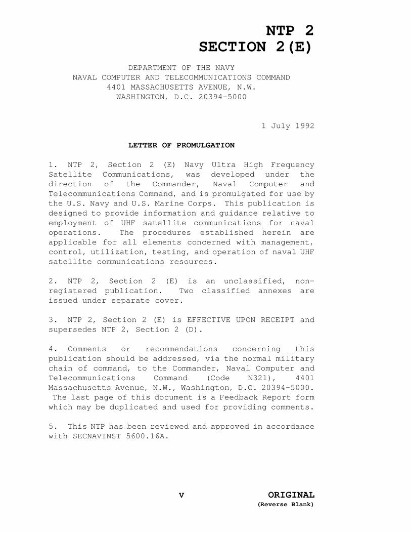
1. NTP 2, Section 2 (E) Navy Ultra High FrequencySatellite Communications, was developed under thedirection of the Commander, Naval Computer andTelecommunications Command, and is promulgated for use bythe U.S. Navy and U.S. Marine Corps. This publication isdesigned to provide information and guidance relative toemployment of UHF satellite communications for navaloperations. The procedures established herein areapplicable for all elements concerned with management,control, utilization, testing, and operation of naval UHFsatellite communications resources.
2. NTP 2, Section 2 (E) is an unclassified, non-registered publication. Two classified annexes areissued under separate cover.
3. NTP 2, Section 2 (E) is EFFECTIVE UPON RECEIPT andsupersedes NTP 2, Section 2 (D).
4. Comments or recommendations concerning thispublication should be addressed, via the normal militarychain of command, to the Commander, Naval Computer andTelecommunications Command (Code N321), 4401Massachusetts Avenue, N.W., Washington, D.C. 20394-5000. The last page of this document is a Feedback Report formwhich may be duplicated and used for providing comments.
5. This NTP has been reviewed and approved in accordancewith SECNAVINST 5600.16A.
V ORIGINAL(Reverse Blank)

NTP 2SECTION 2 (E)
RECORD OF CHANGES AND CORRECTIONS
Enter Change or Correction in Appropriate Column
Identification of Change orCorrection; Reg. No. (if any)
and date of same Date EnteredBy whom entered
(Signature; rank, gradeor
rate; name of command)Change Correction
ORIGINALVII

NTP 2SECTION 2 (E)
RECORD OF CHANGES AND CORRECTIONS
Enter Change or Correction in Appropriate Column
Identification of Change orCorrection; Reg. No. (if any)
and date of same Date EnteredBy whom entered
(Signature; rank, gradeor
rate; name of command)Change Correction
ORIGINALVIII

NTP 2SECTION 2(E)
NAVY ULTRA HIGH FREQUENCY
SATELLITE COMMUNICATIONS
TABLE OF CONTENTS
Title Page . . . . . . . . . . . . . . . . . . . . . . . . . . I
Foreword . . . . . . . . . . . . . . . . . . . . . . . . . . III
Letter of Promulgation . . . . . . . . . . . . . . . . . . . . V
Record of Changes and Corrections . . . . . . . . . . . . . . VII
Table of Contents . . . . . . . . . . . . . . . . . . . . . . IX
PARAGRAPH SUBJECT PAGE
CHAPTER 1
INTRODUCTION
101 Purpose . . . . . . . . . . . . . . . . . . . . . . . 1-1102 Scope . . . . . . . . . . . . . . . . . . . . . . . . 1-1103 Direction . . . . . . . . . . . . . . . . . . . . . . 1-1104 Background . . . . . . . . . . . . . . . . . . . . . 1-4105 Future Applications . . . . . . . . . . . . . . . . . 1-6106 Related Documents . . . . . . . . . . . . . . . . . . 1-8
CHAPTER 2
SYSTEM DESCRIPTION
201 General . . . . . . . . . . . . . . . . . . . . . . . 2-1202 Space Segment . . . . . . . . . . . . . . . . . . . . 2-1203 Earth Segment . . . . . . . . . . . . . . . . . . . 2-26204 RF Terminals . . . . . . . . . . . . . . . . . . . 2-26205 Primary UHF Antenna Subsystems . . . . . . . . . . 2-36206 UHF SATCOM System . . . . . . . . . . . . . . . . . 2-42207 Future Developments - UHF SATCOM Subsystems . . . . 2-49208 Baseband Equipment . . . . . . . . . . . . . . . . 2-56
CHAPTER 3
NAVY ULTRA HIGH FREQUENCY (UHF)
SATELLITE COMMUNICATIONS (SATCOM) CONTROL
301 General . . . . . . . . . . . . . . . . . . . . . . . 3-1302 Authority . . . . . . . . . . . . . . . . . . . . . . 3-1303 Responsibilities for Operational Management . . . . . 3-2304 System Control . . . . . . . . . . . . . . . . . . . 3-6305 Satellite Channelization . . . . . . . . . . . . . 3-10
IX ORIGINAL

NTP 2SECTION 2(E)
PARAGRAPH SUBJECT PAGE
CHAPTER 4
ULTRA HIGH FREQUENCY (UHF) OPERATIONS PROCEDURES
401 General . . . . . . . . . . . . . . . . . . . . . . . 4-1402 Satellite Access Procedures . . . . . . . . . . . . . 4-2403 Priority Structure . . . . . . . . . . . . . . . . . . 4-7404 Power Control . . . . . . . . . . . . . . . . . . . . 4-9405 Radio Frequency Interference (RFI) . . . . . . . . 4-10406 Crisis and Contingency Communications . . . . . . . 4-13
CHAPTER 5
ADMINISTRATIVE PROCEDURES
501 General . . . . . . . . . . . . . . . . . . . . . . . 5-1502 Integrated MILSATCOM (Military Satellite
Communications) Management Information System (IMMIS) . . . . . . . . . . . . . . . . . . 5-1
503 ISDB Submissions . . . . . . . . . . . . . . . . . . 5-2504 Reporting Requirements . . . . . . . . . . . . . . . 5-2505 Operational Training . . . . . . . . . . . . . . . . 5-3
ANNEXES
A FLEET SATELLITE BROADCAST . . . . . . . . . . . . . . A-1B OFFICER IN TACTICAL COMMAND INFORMATION EXCHANGE
SUBSYSTEM (OTCIXS)/TACTICAL DATA INFORMATION EXCHANGE SUBSYSTEM (TADIXS) . . . . . . . . . . . . B-1
C COMMON USER DIGITAL INFORMATION EXCHANGE SUBSYSTEM (CUDIXS) AND NAVAL MODULAR AUTOMATED COMMUNICATIONS SUBSYSTEM (NAVMACS) . . . . . . . . . . . . . . . . C-1
D TACTICAL INTELLIGENCE SUBSYSTEM (TACTICAL) CONFIDENTIAL ISSUED UNDER SEPARATE COVER . . . . . D-1
E DEMAND ASSIGNED MULTIPLE ACCESS (DAMA) SUBSYSTEM . . . . . . . . . . . . . . . . . . . . . E-1
F SUBMARINE SATELLITE INFORMATION EXCHANGE SUBSYSTEM II (SSIXS II) . . . . . . . . . . . . . . . . . . . F-1
G FLEET IMAGERY SUPPORT TERMINAL (FIST) . . . . . . . . G-1H PROCEDURES FOR THE TACTICAL RECEIVE EQUIPMENT (TRE)
AND TACTICAL RELATED APPLICATIONS (TRAP) BROADCAST, SECRET ISSUED UNDER SEPARATE COVER . . . . . . . . H-1
I ACRONYMS . . . . . . . . . . . . . . . . . . . . . . I-1J GLOSSARY . . . . . . . . . . . . . . . . . . . . . . J-1INDEX . . . . . . . . . . . . . . . . . . . . . . . . INDEX-1LIST OF EFFECTIVE PAGES . . . . . . . . . . . . . . . . . . LEP-1COMMUNICATIONS PROCEDURES FEEDBACK REPORT
X ORIGINAL

NTP 2SECTION 2(E)
PARAGRAPH SUBJECT PAGE
LIST OF FIGURES
1-1 FLTSATCOM Relationships . . . . . . . . . . . . . . . 1-21-2 Pillars of the Copernicus Architecture . . . . . . . 1-8
2-1 FLTSAT Coverage Areas . . . . . . . . . . . . . . . . 2-42-2 Deployed FLTSAT . . . . . . . . . . . . . . . . . . . 2-42-3 FLTSAT Communications Subsystem Block Diagram . . . . 2-72-4 LEASAT Coverage Areas . . . . . . . . . . . . . . . . 2-92-5 Deployed LEASAT . . . . . . . . . . . . . . . . . . . 2-92-6 LEASAT Communications Subsystem Block Diagram . . . 2-142-7 UFO Deployed Satellite . . . . . . . . . . . . . . 2-142-8 GAPFILLER Coverage Areas . . . . . . . . . . . . . 2-192-9 Deployed GAPFILLER . . . . . . . . . . . . . . . . 2-192-10 Deployed INMARSAT . . . . . . . . . . . . . . . . . 2-232-11 AN/FSC-79 Antenna . . . . . . . . . . . . . . . . . 2-272-12 AN/WSC-5(V) Communications Subsystem Block
Diagram . . . . . . . . . . . . . . . . . . . . . 2-282-13 AN/WSC-3(V) Communications Subsystem Block
Diagram . . . . . . . . . . . . . . . . . . . . . 2-292-14 OE-82B/WSC-1(V) Antenna Group . . . . . . . . . . . 2-372-15 OE-82C/WSC-1(V) Antenna Group . . . . . . . . . . . 2-382-16 AN/WSC-5(V) Shore Station Antenna . . . . . . . . . 2-392-17 HR9NP Antenna . . . . . . . . . . . . . . . . . . . 2-402-18 Andrew 58622 Antenna . . . . . . . . . . . . . . . 2-402-19 TACO H-124 Antenna . . . . . . . . . . . . . . . . 2-412-20 TACO H-084 Antenna . . . . . . . . . . . . . . . . 2-412-21 HSFB Block Diagram . . . . . . . . . . . . . . . . 2-532-22 Mini-DAMA Configuration . . . . . . . . . . . . . . 2-55
3-1 FLTSATCOM Control System . . . . . . . . . . . . . . 3-6
4-1 Equatorial Satellite Antenna Pointing Group . . . . . 4-6
A-1 Fleet Satellite Broadcast Subsystem . . . . . . . . . A-3
B-1 TACTINTEL Shore Configuration . . . . . . . . . . . . B-1B-2 TADIXS A Network . . . . . . . . . . . . . . . . . . B-2B-3 OTCIXS Block Diagram . . . . . . . . . . . . . . . . B-3B-4 TADIXS A Block Diagram . . . . . . . . . . . . . . . B-5
C-1 CUDIXS and NAVMACS . . . . . . . . . . . . . . . . . C-3
D-1 TACINTEL Shore Configuration . . . . . . . . . . . . D-3D-2 TACINTEL Subscriber Configuration . . . . . . . . . . D-5
E-1 A Typical OK-454(V) WSC Installation . . . . . . . . E-4E-2 A Typical Ok-455(V) WSC Installation . . . . . . . . E-5E-3 A Typical OK-481(V)/FSC Installation . . . . . . . . E-6E-4 OW-101/FSC Installation . . . . . . . . . . . . . . . E-7E-5 Basic DAMA Frame Format . . . . . . . . . . . . . . . E-8
XI ORIGINAL

NTP 2SECTION 2(E)
PARAGRAPH SUBJECT PAGE
LIST OF FIGURES (Continued)
E-6 Typical DAMA Frame Format . . . . . . . . . . . . . E-10
F-1 SSIXS . . . . . . . . . . . . . . . . . . . . . . . . F-2
G-1 Fundamental FIST Satellite Circuit . . . . . . . . . G-2G-2 FIST UHF SATCOM Shore/Afloat Configurations . . . . . G-3G-3 Functional Block Diagram . . . . . . . . . . . . . . G-4
H-1 Worldwide TRAP Network . . . . . . . . . . . . . . . H-3H-2 TRAP Offset Frequency Concept and Channel Time
Sharing Time . . . . . . . . . . . . . . . . . . . H-5H-3 TRAP to TADIXS A Gateways . . . . . . . . . . . . . . H-6
LIST OF TABLES
2-1 FLTSAT, LEASAT, and UFO Key Characteristics . . . . . 2-12-2 FLTSAT Frequency Plan . . . . . . . . . . . . . . . . 2-52-3 FLTSAT Channel 23 Wideband Frequency Plan . . . . . . 2-62-4 LEASAT Frequency Plan . . . . . . . . . . . . . . . 2-122-5 LEASAT Channel 2 Wideband Frequency Plan . . . . . 2-132-6 Channel 1 Frequency Plan . . . . . . . . . . . . . 2-162-7 UFO Frequency Plan . . . . . . . . . . . . . . . . 2-172-8 GAPFILLER 500-kHz Bandwidth Frequencies . . . . . . 2-202-9 INMARSAT Frequency Plan . . . . . . . . . . . . . . 2-232-10 NATO IV Characteristics . . . . . . . . . . . . . . 2-242-11 NATO Terminals . . . . . . . . . . . . . . . . . . 2-252-12 SKYNET 4 Payload Characteristics . . . . . . . . . 2-252-13 AN/WSC-3 Variations . . . . . . . . . . . . . . . . 2-302-14 AN/TSC-96(V) Terminal Equipment . . . . . . . . . . 2-322-15 ON-143(V)/USQ Variations . . . . . . . . . . . . . 2-57
3-1 U.S. Navy UHF SATCOM Control Activities . . . . . . . 3-53-2 FLTSAT Channel Allocation . . . . . . . . . . . . . 3-103-3 LEASAT Channel Allocation . . . . . . . . . . . . . 3-11
4-1 User Priority Values . . . . . . . . . . . . . . . . 4-84-2 Satellite Identification Data . . . . . . . . . . . 4-12
5-1 PQS for UHF SATCOM . . . . . . . . . . . . . . . . . 5-6
A-1 Fleet Satellite Broadcast Transmission Modes . . . . A-3A-2 Fleet Satellite Broadcast Subsystem Equipment
Configuration . . . . . . . . . . . . . . . . . . . A-5A-3 Fleet Satellite Broadcast RF Terminal
Installations . . . . . . . . . . . . . . . . . . . A-6A-4 BCS/ABCS Assignments . . . . . . . . . . . . . . . . A-6
D-1 TACINTEL Nets and Link Control Facilities . . . . . . D-2
XII ORIGINAL

NTP 2SECTION 2(E)
Paragraph Subject Page
LIST OF TABLES (Continued)
E-1 DAMA Control-Monitor Group Configurations . . . . . . E-2
F-1 SSIXS II Equipment . . . . . . . . . . . . . . . . . F-4F-2 SSIXS II Shore Locations . . . . . . . . . . . . . . F-5H-1 TRAP Broadcast Node Locations and Functions . . . . . .H-4H-2 FLTSATCOM Space Assets . . . . . . . . . . . . . . .H-8 H-3 TRAP Management . . . . . . . . . . . . . . . . . . H-12H-4 TRAP Broadcast Nodes . . . . . . . . . . . . . . . H-13H-5 NCTAMS/FTOC . . . . . . . . . . . . . . . . . . . . H-14
XIII ORIGINAL

NTP 2SECTION 2(E)
CHAPTER 1
INTRODUCTION
101. PURPOSE
The purpose of this section is to promulgateinformation concerning direction, management, and controlof the ultra high frequency (UHF) satellitecommunications (SATCOM) system. It is applicable toairborne, afloat, and ashore (fixed or mobile)subscribers of the Fleet Satellite Communications(FLTSATCOM) system (including Fleet Satellite (FLTSAT),Leased Satellite (LEASAT), GAPFILLER, and UHF Follow-on(UFO)).
102. SCOPE
This section of the Naval TelecommunicationsProcedures 2 (NTP 2) is intended as a source ofinformation to assist in the planning of FLTSATCOMoperations. It is an applicable information source fornaval staffs at all echelons and for supervisors ofterminal operators. It is intended to complementexisting directives, publications, and other NTP's. NTP2, Sections 1 and 3 provide operating procedures forsuper high frequency (SHF) and extremely high frequency(EHF) SATCOM, respectively.
103. DIRECTION
a. The FLTSATCOM system is a resource of theDepartment of Defense (DOD), which is managed andoperated by the U.S. Navy in accordance with prioritiesestablished by the Chairman of the Joint Chiefs of Staff(CJCS). U.S. Air Force capabilities are employed toexecute stationkeeping tasks for the space segment. Itis in this joint context that the policies and procedureswhich govern FLTSATCOM system operations must beconsidered. The relationships of these parties arereflected in figure 1-1 and described in the followingparagraphs.
b. Chairman of the Joint Chiefs of Staff. The
1-1 ORIGINAL

NTP 2SECTION 2(E)
Chairman of the Joint Chiefs of Staff allocates militarysatellite communications (MILSATCOM) resources to satisfynational defense requirements and specifies operationalprocedures and responsibilities for system managers,operators, and users. The Chairman of the Joint Chiefsof Staff also recommends to the Secretary of Defensethose actions required for shared use of MILSATCOM assetsand services and reviews proposed cooperative agreementsbetween the Department of Defense and other agencies orgovernments relative to shared use. The Chairman of theJoint Chiefs of Staff also reviews and approves userconnectivity requirements, defines the process forrequirements documentation, and approvespositioning/repositioning of satellites.
Figure 1-1FLTSATCOM Relationships
c. Commander in Chief, U.S. Space Command
1-2 ORIGINAL

NTP 2SECTION 2(E)
(USCINCSPACE). This unified commander is responsible tothe Chairman of the Joint Chiefs of Staff for maintainingthe health, status, and survivability of the SATCOM spacesegment. In this role, USCINCSPACE plans and executesUHF spacecraft tracking, stationkeeping, ephemeris datageneration, and payload control.
d. Defense Information Systems Agency (DISA).This agency (formerly the Defense Communications Agency)is the DOD-designated manager of the DefenseCommunications System (DCS). DISA designs, engineers,and develops the DCS to satisfy validated requirements.DISA has overall responsibility for planning, developing,and supporting the command, control, communications (C3),and information systems that serve the needs of the National Command Authorities. The Director, DISA isresponsible to the Chairman of the Joint Chiefs of Stafffor operational matters as well as requirementsassociated with the joint planning process.
e. Chief of Naval Operations (CNO). TheDepartment of the Navy (DON) is the FLTSATCOM systemmanager. Acting for DON, CNO approves and directs theimplementation of the FLTSATCOM system programs. Withinthe Navy staff, the Director, Space and ElectronicWarfare (OP-094) is tasked with overall responsibilityfor SATCOM planning and development, and for thesponsorship of the FLTSATCOM program in the budgetingprocess. The Director, Information Transfer Division(OP-941) provides policy for operation, maintenance, andmanagement of the Naval Computer and TelecommunicationsSystem (NCTS). OP-941 sponsors and authorizesdevelopment and procurement of general communicationsequipment, and determines personnel and trainingrequirements for communications systems. The Director,Navy Space Systems Division (OP-943) is responsible forprogram coordination and acquisition of space systems.OP-943 also assesses future SATCOM concepts, policies,and applications. This office also coordinates U.S. Navyrequirements with the Chairman of the Joint Chiefs ofStaff, the other Services, and DISA. This includesmanaging the functions of development, procurement,installation, operation, and logistical support of SATCOMsystems.
1-3 ORIGINAL
NTP 2SECTION 2(E)
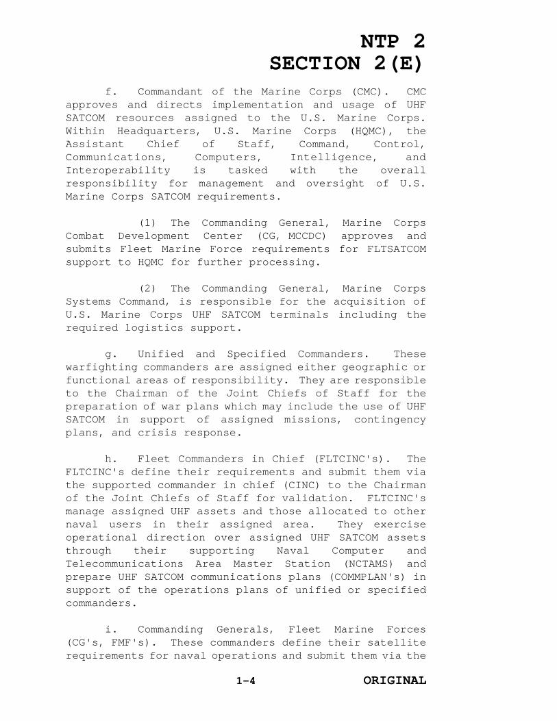
f. Commandant of the Marine Corps (CMC). CMCapproves and directs implementation and usage of UHFSATCOM resources assigned to the U.S. Marine Corps.Within Headquarters, U.S. Marine Corps (HQMC), theAssistant Chief of Staff, Command, Control,Communications, Computers, Intelligence, andInteroperability is tasked with the overallresponsibility for management and oversight of U.S.Marine Corps SATCOM requirements.
(1) The Commanding General, Marine CorpsCombat Development Center (CG, MCCDC) approves andsubmits Fleet Marine Force requirements for FLTSATCOMsupport to HQMC for further processing.
(2) The Commanding General, Marine CorpsSystems Command, is responsible for the acquisition ofU.S. Marine Corps UHF SATCOM terminals including therequired logistics support.
g. Unified and Specified Commanders. Thesewarfighting commanders are assigned either geographic orfunctional areas of responsibility. They are responsibleto the Chairman of the Joint Chiefs of Staff for thepreparation of war plans which may include the use of UHFSATCOM in support of assigned missions, contingencyplans, and crisis response.
h. Fleet Commanders in Chief (FLTCINC's). TheFLTCINC's define their requirements and submit them viathe supported commander in chief (CINC) to the Chairmanof the Joint Chiefs of Staff for validation. FLTCINC'smanage assigned UHF assets and those allocated to othernaval users in their assigned area. They exerciseoperational direction over assigned UHF SATCOM assetsthrough their supporting Naval Computer andTelecommunications Area Master Station (NCTAMS) andprepare UHF SATCOM communications plans (COMMPLAN's) insupport of the operations plans of unified or specifiedcommanders.
i. Commanding Generals, Fleet Marine Forces(CG's, FMF's). These commanders define their satelliterequirements for naval operations and submit them via the
1-4 ORIGINAL

NTP 2SECTION 2(E)
FLTCINC for further validation. Requests in support ofU.S. Marine Corps operations are submitted to CG, MCCDCfor approval and further processing by HQMC and the JointStaff.
j. Commander, Naval Space Command(COMNAVSPACECOM). This commander is the systemoperational manager for communications satellite systemsfor which the U.S. Navy is the system manager. Asoperational manager, COMNAVSPACECOM exercises control ofassigned satellites by planning for location andrelocation. COMNAVSPACECOM also determines parametersrequired for operation of the satellite system, such aspower, bandwidth, and operating frequencies.COMNAVSPACECOM coordinates with DISA and Commander, NavalComputer and Telecommunications Command (COMNAVCOMTELCOM)concerning naval SATCOM operations and planning.COMNAVSPACECOM is also the Naval Component Commanderunder USCINCSPACE.
k. COMNAVCOMTELCOM. This commander exercisesauthority over all elements of the Naval Computer andTelecommunications Command and is the communicationsmanager for SATCOM systems and subsystems. As thecommunications manager, COMNAVCOMTELCOM operates theearth segment within assigned parameters in accordancewith prescribed procedures, and schedules access time forauthorized users of SATCOM services. NCTAMS's personnelact on behalf of the FLTCINC's to manage SATCOM assetsallocated to those FLTCINC's. COMNAVCOMTELCOM retainscommand of all subordinate commands providingcommunications services to the FLTCINC's.
l. Commanding Officer, NCTAMS. Under theauthoritative direction and control of the respectiveFLTCINC, each NCTAMS will maintain for COMNAVCOMTELCOM,the operational direction and management control of thoseassigned assets of the NCTS.
104. BACKGROUND
a. From the early 1900's, the U.S. Navy relied onhigh frequency radio as the principal transmission mediafor long distance communications. This situation began
1-5 ORIGINAL

NTP 2SECTION 2(E)
to change in 1965 when the three Services initiatedstudies on the use of SATCOM. Lincoln LaboratoryExperimental Satellite 5 (LES 5), a UHF repeatersatellite was placed into high orbit on July 1, 1967. InSeptember 1968, LES 6 was launched in further support ofthe tactical communications study program. Anexperimental tactical communications satellite (TACSAT-1)was launched in February 1969. TACSAT-1 was used by allthe military services in the assessment of the tacticalrole of SATCOM. Three Maritime Satellite (MARISAT)system satellites developed by the CommunicationsSatellite (COMSAT) Corporation were placed in orbitover the Atlantic (LANT), Pacific (PAC), and IndianOceans (IO) during 1976. The U.S. Navy leased the UHFtransponder of each satellite and referred to theseassets as GAPFILLER. This title distinguished the U.S.Navy leased capability from the rest of MARISAT andidentified their function as a gap filling measurepending the launch of FLTSAT's. The six FLTSAT'slaunched between 1978 and 1989 provided the initialFLTSATCOM system. In addition, four satellites wereleased between 1984 and 1990 from Hughes Aircraft Company(now Hughes Communication Services, Incorporated) underthe LEASAT program.
b. The FLTSATCOM system has been redefined toinclude the FLTSAT's, LEASAT's, and GAPFILLER satellites.Three LEASAT's are now property of the Department ofDefense, and the remaining LEASAT will become DOD-ownedat a future date. The UFO program will providesatellites to replenish the aging FLTSATCOM system. TheFLTSATCOM satellites are in four equatorialgeosynchronous orbits over the LANT, continental UnitedStates, PAC, and IO areas thus providing worldwide UHFcoverage. Details on the FLTSATCOM satellites are inchapter 2.
c. Air Force Satellite Communications (AFSATCOM)Program. This program provides reliable, enduring,worldwide C3 to designated Single Integrated OperationalPlan (SIOP)/nuclear capable forces for emergency actionmessage (EAM) dissemination, CJCS/CINC internetting,force direction, and force reportback communications.Additionally, AFSATCOM provides support for
1-6 ORIGINAL

NTP 2SECTION 2(E)
contingency/crisis operations, exercises, and trainingfor a limited number of high priority non-SIOP users.The AFSATCOM space segment consists of U.S. Air Forcemanaged transponders (offering 500-kilohertz (kHz)wideband channels and 5-kHz narrowband channels)installed on FLTSAT's and LEASAT's and a terminal segmentconsisting of a family of modular UHF or SHF ground andairborne terminals. The U.S. Air Force is the systemmanager for this system. The Satellite Data System (SDS)also provides satellite platforms for AFSATCOMtransponders. The satellites of this system are inhighly inclined elliptical orbits that providecoverage over the north polar regions. The AFSATCOMtransponder aboard SDS consists of twelve 5-kHznarrowband channels. Control of these channels isexercised by the U.S. Air Force Primary Control Center.Additional AFSATCOM information is in chapter 2.
d. UFO. The UFO satellite system is designed toprovide continuous, reliable, global UHF SATCOM tomobile and shore-based users. Launching of UFOsatellites is scheduled to commence in 1992 and willeventually replace the existing FLTSAT and LEASATsatellites. When launching is complete in 1996, theCJCS-approved constellation will comprise eight UFOsatellites over four ocean areas and one on-orbit spare.All UFO satellites have UHF and SHF capabilities. Inaddition, satellites 4 and beyond will have an EHFcapability. The UHF payload consists of twenty-one 5-kHzchannels, seventeen 25-kHz channels, and a broadcastchannel with an SHF uplink.
e. North Atlantic Treaty Organization (NATO) UHFSATCOM Subsystem. The NATO UHF SATCOM subsystem consistsof two UHF channels on the NATO IV SHF satellite. Itprovides a transmission media for connectivity betweensubscribers and the NATO Integrated CommunicationsSystem. U.S. Navy vessels operating in NATO areas may berequired to enter the NATO UHF SATCOM subsystem.Additional information regarding the NATO UHF SATCOMsubsystem is discussed in chapter 2.
f. International Maritime Satellite (INMARSAT).The commercial INMARSAT system can be used to provide
1-7 ORIGINAL

NTP 2SECTION 2(E)
support to surface units at sea. The CNO has establishedguidance and procedures for acquiring INMARSAT equipment.See NTP 10 (NTP 4 after October 1992) and chapter 2 ofthis NTP for additional information regarding INMARSAT.
105. FUTURE APPLICATIONS
a. The increasing requirement to provide near-real-time information to afloat commanders hasnecessitated a reevaluation and realignment of the meansavailable to satisfy naval circuit requirements. Futureapplications of UHF SATCOM are being refined to meetthese requirements.
b. Copernicus Architecture. The CopernicusArchitecture involves a major restructuring of U.S. Navycommand, control, communications, computers andintelligence (C4I) to put the warfighter at the center ofthe command and control universe by providing theinformation needed, when it is required. The CopernicusArchitecture accomplishes this by collecting,correlating, and fusing data to produce and efficientlydisseminate (only once) that information that isrequired by the battle group/battle force commander ina format that can be readily used. The four majorcomponents of Copernicus are the CINC Command Complex(CCC) ashore, the Tactical Command Centers (TCC) afloat,the Global Information Exchange Systems (GLOBIXS), andTactical Data Information Exchange Systems (TADIXS). TheU.S. Navy SATCOM architecture will support Copernicus byproviding the media for data collection and for theTADIXS networks. The Communication Support System (CSS)is the major vehicle for integrating all of the U.S.Navy's SATCOM assets into Copernicus. Figure 1-2illustrates the major components (pillars) of theCopernicus Architecture. The following paragraphsbriefly describe the TADIXS and the CSS.
(1) TADIXS. These systems are not thephysical nets currently in use, but rather logical nets,established at the request of, and in the mix desired by,the tactical commander. This operational flexibility isat the heart of the Copernican philosophy of placing the
1-8 ORIGINAL

NTP 2SECTION 2(E)
operator at the center. Technologically, this will be
Figure 1-2Pillars of the Copernicus Architecture
accomplished by addressing data packets across theGLOBIXS, over the CCC local area network, to the CSS,onward via the TADIXS to the TCC for assimilation andfurther dissemination as required.
(2) The CSS. CSS is a communications sub-architecture that enhances battle force communicationsconnectivity, flexibility, and survivability throughmulti-media access and media sharing. The CSS permitsusers to share total network capacity on a prioritydemand basis in accordance with the tactical commander'scurrent COMMPLAN. Automated network monitoring andmanagement capabilities are also provided by the CSS toassist operators in the real-time allocation ofcommunications resources according to selected criteria(e.g., suitability, antijam, priority, etc.).
106. RELATED DOCUMENTS
1-9 ORIGINAL

NTP 2SECTION 2(E)
The following documents provide guidance orassistance in the planning and implementation of U.S.Navy UHF SATCOM systems.
a. CJCS Memorandum of Policy (MOP) 37 MilitarySatellite Communications (MILSATCOM) Systems. This MOPis published to establish operational policy andprocedures and provide guidance on MILSATCOM systems asdirected by DOD Directive 5105.44. Procedural provisionsof this document apply to all users of MILSATCOM systems.It concerns overall MILSATCOM policy and objectives;responsibilities of the Chairman of the Joint Chiefs ofStaff, Military Departments, MILSATCOM system managers,the CINC's, the Joint Communications Satellite Center,Director, DISA; and operational policy and proceduresrelative to MILSATCOM systems planning and employment.
b. Allied Communications Publication (ACP) 176NATO Supplement 1 (NATO Naval and Maritime AirCommunication Instructions and Organization). Thispublication (classified NATO CONFIDENTIAL) amplifies thebasic provisions of ACP 176 by describing NATO navaland maritime communications instructions andorganizations. Chapter 6 of the supplement specificallyaddresses satellite systems for naval and maritime use.
c. Integrated SATCOM Database (ISDB). Thisdatabase (formerly User Requirements Database) isadministered by DISA under direction of the Chairman ofthe Joint Chiefs of Staff and is the single source ofinformation concerning validated SATCOM requirements.ISDB submissions are addressed in chapter 5.
d. Communications Annexes to FLTCINC OperationOrders. These documents are the FLTCINC's COMMPLAN's tosupport the joint and naval component commanders'requirements. The communications systems, procedures andcoordinating instructions for communications operationsduring exercises and wartime are identified in thecommunications annexes.
e. Fleet Telecommunications Procedures (FTP).FTP's are publications issued jointly by NCTAMS EasternPacific (EASTPAC) and NCTAMS Western Pacific (WESTPAC)for the PAC/IO areas and by NCTAMS LANT and NCTAMSMeditteranean (MED) for the LANT and MED areas. TheFTP's promulgate standard telecommunications proceduresspecific to these ocean areas, and amplify information inthe NTP's. Changes to the FTP may initially bepromulgated by Communications Information Bulletins
1-10 ORIGINAL

NTP 2SECTION 2(E)
(CIB's).
f. CIB's. CIB's are promulgated by the NCTAMS toprovide accurate and readily accessible referenceinformation on specific tactical communications subjects.CIB's provide communications personnel with currentprocedural information applicable to a specificcommunications area and normally are promulgated bymessage. Changes in UHF satellite operations,procedures, or channelization, for example, may initiallybe identified via the CIB's before incorporation into anFTP or NTP. Ships and units are required to maintain acomplete and current file of CIB's.
1-11 ORIGINAL

NTP 2SECTION 2(E)
CHAPTER 2
SYSTEM DESCRIPTION
201. GENERAL
The U.S. Navy Ultra High Frequency (UHF) FleetSatellite Communications (FLTSATCOM) system, consistingof Fleet Satellites (FLTSAT's), Leased Satellites(LEASAT's), and portions of leased Maritime Satellites(MARISAT's), provides worldwide communicationconnectivity with all naval ships and submarines, certainland and air platforms, and fixed shore sites. Theportion of MARISAT leased by the U.S. Navy is referred toas GAPFILLER to distinguish the special management andcontrol functions from that of the MARISAT. The UHFFollow-on (UFO) program will provide replacementsatellites for the aging FLTSAT constellation beginninglate in 1992. The FLTSATCOM system comprises space,earth, and control segments. The space and earthsegments consist of satellites, earth terminals,subscribers, and subsystems described in this chapter.Some satellite systems discussed in this chapter (e.g.,the United Kingdom SKYNET 4 and North Atlantic TreatyOrganization IV (NATO IV) satellites) are not part ofFLTSATCOM but may be called upon to provide service. Thecontrol segment is described in chapter 3.
202. SPACE SEGMENT
The space segment comprises four FLTSAT's, fourLEASAT's, and two GAPFILLER satellites, positioned toprovide worldwide coverage between 70o north latitude and70o south latitude. Table 2-1 compares keycharacteristics of the FLTSAT, LEASAT, and UFO spacesegments.
a. FLTSAT. FLTSAT is an element of the U.S. NavyFLTSATCOM system and is part of the worldwide Departmentof Defense (DOD) communication system. FLTSAT coverageareas are illustrated in figure 2-1. The satellite iscomprised of two major components: a payload module anda spacecraft module with a solar array. The payloadmodule contains the UHF and super high frequency (SHF)communications equipment (including antennas), and thetelemetry, tracking, and command (TT&C) antennas. Thecommunications equipment is mounted on the underside ofpanels that cover the payload section of the spacecraft.The earth sensors, attitude and velocity control,electrical power and distribution, TT&C, and reactioncontrol equipment are part of the spacecraft module.
2-1 ORIGINAL

NTP 2SECTION 2(E)
FLTSAT's 7 and 8 also have an extremely high frequency(EHF) capability as discussed in Naval TelecommunicationsProcedures (NTP) 2 Section 3.
(1) Satellite Characteristics. Thespacecraft is a three-axis stabilized satellite. Theantennas are oriented toward the center of the earth bythe earth sensor subsystem and the solar array isoriented toward the sun by a clocked drive subsystem.The expected design life for the spacecraft is ten years.Figure 2-2 illustrates a deployed FLTSAT.
(a) Attitude and Velocity Control. Theattitude and velocity control subsystem together with thereaction control subsystem automatically maintainspacecraft stability. A low-level thrust system correctsfor roll or pitch errors, detected by the earth sensor,with two sets of thrusters and a reaction wheel.Momentum of the stored reaction wheel and the angularrate of orbit provide static interaction to control yaw.When large velocity corrections are needed, the yawattitude is controlled by the high-level reaction controlthrusters. Two sets of eight thrusters provide the high-level thrust.
2-2 ORIGINAL

NTP 2SECTION 2(E)
SATELLITECHARACTERISTICS
SATELLITE
FLTSAT LEASAT UFO
EffectiveIsotropic Radiated Power(EIRP)
Two 25-kHzchannels(FLTBCST) withEIRP of 28 dBW
Six 25-kHz channelswith EIRP of 26 dBW
Seventeen 25-kHzchannels EIRP: Two channels 28dBW Fifteen channels26 dBW
Eight 25-kHzchannels withEIRP of 26 dBW
One 25-kHz channel(FLTBCST) with EIRPof 26 dBW
One 25-kHz channel(FLTBCST) with EIRPof 28 dBW
Twelve 5-kHzchannels withEIRP of 16.5 dBW
Five 5-kHz channelswith EIRP of16.5 dBW
Twenty-one 5-kHzchannels with(FLTBCST) EIRP of20 dBW
One 500-kHzchannel with EIRPof 27.1 dBW
One 500-kHz channelwith EIRP of 28 dBW
UHF EarthCoverage Antenna
19o 19o 19o
Frequency Plans 3 4 4
Satellite On-Orbit Weight
2,300 pounds 2,868 pounds 2,364 pounds
Receive Gain-to-Noise Temperature(G/T)
-16 dB/ok Six 25-kHz, One500-kHz, and Five5-kHz channels -18dB/ok One 25-kHz channel-20 dB/ok
≥ -16 dB/ok for 5-kHz and 25-kHz channels
Lifetime(expected designlife)
10 years 10 years 14 years
FLTSAT, LEASAT, and UFO Key CharacteristicsTable 2-1
2-3 ORIGINAL
NTP 2SECTION 2(E)
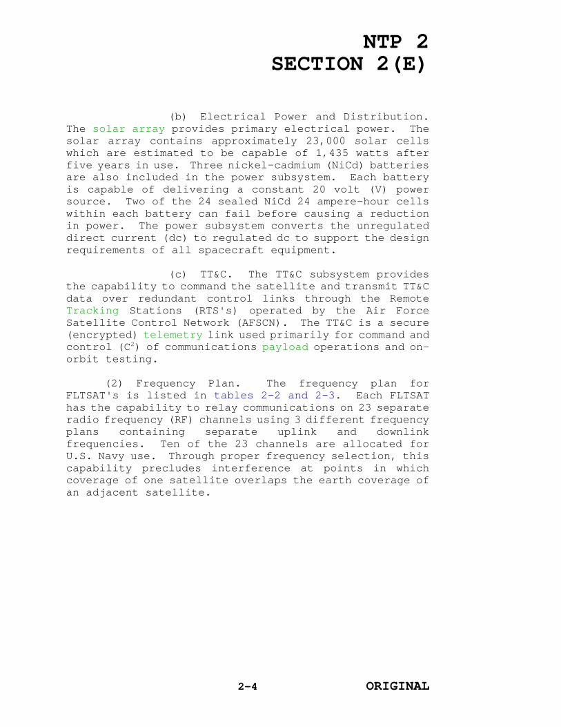
(b) Electrical Power and Distribution.The solar array provides primary electrical power. Thesolar array contains approximately 23,000 solar cellswhich are estimated to be capable of 1,435 watts afterfive years in use. Three nickel-cadmium (NiCd) batteriesare also included in the power subsystem. Each batteryis capable of delivering a constant 20 volt (V) powersource. Two of the 24 sealed NiCd 24 ampere-hour cellswithin each battery can fail before causing a reductionin power. The power subsystem converts the unregulateddirect current (dc) to regulated dc to support the designrequirements of all spacecraft equipment.
(c) TT&C. The TT&C subsystem providesthe capability to command the satellite and transmit TT&Cdata over redundant control links through the RemoteTracking Stations (RTS's) operated by the Air ForceSatellite Control Network (AFSCN). The TT&C is a secure(encrypted) telemetry link used primarily for command andcontrol (C2) of communications payload operations and on-orbit testing.
(2) Frequency Plan. The frequency plan forFLTSAT's is listed in tables 2-2 and 2-3. Each FLTSAThas the capability to relay communications on 23 separateradio frequency (RF) channels using 3 different frequencyplans containing separate uplink and downlinkfrequencies. Ten of the 23 channels are allocated forU.S. Navy use. Through proper frequency selection, thiscapability precludes interference at points in whichcoverage of one satellite overlaps the earth coverage ofan adjacent satellite.
2-4 ORIGINAL

NTP 2SECTION 2(E)
Figure 2-1FLTSAT Coverage Areas
Figure 2-2Deployed FLTSAT
2-5 ORIGINAL

NTP 2SECTION 2(E)
CHANNEL/NOMINALBAND-WIDTH
PLANDOWNLINK
FRE-QUENCY(MHz)
UPLINKFRE-
QUENCY(MHz)
CHANNEL/NOMINALBAND-WIDTH
PLANDOWNLINK
FRE-QUENCY(MHz)
UPLINKFRE-
QUENCY(MHz)
125 kHz
ABC
250.450250.550250.650
SHF*SHF*SHF*
135 kHz
ABC
243.960244.060244.160
317.060317.160317.260
225 kHz
ABC
251.950252.050252.150
292.950293.050293.150
145 kHz
ABC
243.965244.065244.165
317.065317.165317.265
325 kHz
ABC
253.650253.750253.850
294.650294.750294.850
155 kHz
ABC
243.970244.070244.170
317.070317.170317.270
425 kHz
ABC
255.350255.450255.550
296.350296.450296.550
165 kHz
ABC
243.975244.075244.175
317.075317.175317.275
525 kHz
ABC
256.950257.050257.150
297.950298.050298.150
175 kHz
ABC
243.980244.080244.180
317.080317.180317.280
625 kHz
ABC
258.450258.550258.650
299.450299.550299.650
185 kHz
ABC
243.985244.085244.185
317.085317.185317.285
725 kHz
ABC
265.350265.450265.550
306.350306.450306.550
195 kHz
ABC
243.990244.090244.190
317.090317.190317.290
825 kHz
ABC
266.850266.950267.050
307.850307.950308.050
205 kHz
ABC
243.995244.095244.195
317.095317.195317.295
925 kHz
ABC
268.250268.350268.450
309.250309.350309.450
215 kHz
ABC
244.000244.100244.200
317.100317.200317.300
1025 kHz
ABC
269.750269.850269.950
310.750310.850310.950
225 kHz
ABC
244.010244.110244.210
317.110317.210317.310
115 kHz
ABC
243.945244.045244.145
317.045317.145317.245
23500 kHz
**
ABC
260.600261.700262.300
294.200295.300295.900
125 kHz
ABC
243.955244.055244.155
317.055317.155317.255
Notes:* Uplink frequency is SHF from 7.9to 8.4 GHz on Channel 1.** See table 2-3 for discretefrequency breakdown of channel 23.
FLTSAT Frequency PlanTable 2-2
2-6 ORIGINAL

NTP 2SECTION 2(E)
SUBCHANNEL
PLANDOWNLINK
FRE-QUENCY(MHz)
UPLINKFRE-
QUENCY(MHz)
SUBCHANNEL
PLANDOWNLINK
FRE-QUENCY(MHz)
UPLINKFRE-
QUENCY(MHz)
1ABC
260.350261.450262.050
293.950295.050295.650
12ABC
260.625261.725262.325
294.225295.325295.950
2ABC
260.375261.475262.075
293.975295.075295.675
13ABC
260.650261.750262.350
294.250295.350295.950
3ABC
260.400261.500262.100
294.000295.100295.700
14ABC
260.675261.775262.375
294.275295.375295.975
4ABC
260.425261.525262.125
294.025295.125295.725
15ABC
260.700261.800262.400
294.300295.400296.000
5ABC
260.450261.550262.150
294.050295.150295.750
16ABC
260.725261.825262.425
294.325295.425296.025
6ABC
260.475261.575262.175
294.075295.175295.775
17ABC
260.750261.850262.450
294.350295.450296.050
7ABC
260.500261.600262.175
294.100295.200295.775
18ABC
260.775261.875262.475
294.375295.475295.075
8ABC
260.525261.625262.225
294.125295.225295.825
19ABC
260.800261.900262.500
294.400295.500296.100
9ABC
260.550261.650262.250
294.150295.225295.850
20ABC
260.825261.925262.525
294.425295.525296.125
10ABC
260.575261.675262.275
294.175295.275295.875
21ABC
266.850261.450262.550
294.450295.550296.150
11ABC
260.600261.700262.300
294.200295.300295.900
Table 2-3FLTSAT Channel 23 Wideband Frequency Plan
2-7 ORIGINAL

NTP 2SECTION 2(E)
(3) Satellite Configuration. Each satellitehas 23 channels consisting of ten 25-kilohertz (kHz)channels; twelve 5-kHz channels; and one 500-kHz channel.Each 25-kHz UHF downlink channel has its own separatetransponder. The SHF RF uplink signal is translated toa UHF downlink frequency for the fleet satellitebroadcast. The FLTSAT radiated RF output power is fixedas listed in table 2-1. The 500-kHz transponder (dividedinto 25-kHz channels) supports multiple users andrequires power balancing to avoid adjacent channelinterference. The FLTSAT communications subsystem blockdiagram in figure 2-3 illustrates the functionalrelationship of the communications components.
Figure 2-3FLTSAT Communications Subsystem Block Diagram
(4) Antenna Array. An array of antennas ismounted on the payload module as illustrated in figure 2-3. This array consists of: 1) a 16-foot parabolic UHFtransmit antenna with a backfire, bifilar helix feed; 2)an 18-turn helical UHF receive antenna; 3) an SHF horn;and 4) a TT&C antenna. The SHF horn antenna looks
2-8 ORIGINAL

NTP 2SECTION 2(E)
through a square hole within the parabolic subreflectorof the UHF transmit antenna. The hole is covered with acoarse mesh that is transparent at super high frequenciesand reflective at ultra high frequencies. The TT&Cantenna is the conical spiral antenna mounted on the endof the UHF transmit antenna mast.
b. LEASAT. LEASAT is an element of the FLTSATCOMsystem and part of the worldwide DOD tacticalcommunications system. Coverage areas are illustrated infigure 2-4. LEASAT's are used by the U.S. Navy, U.S.Marine Corps, U.S. Air Force, Department of Defense, andother government agencies. The initial service date forLEASAT was in 1984. Four satellites were leased fromHughes Communications Services, Incorporated (HCSI). Theoriginal leases covering LEASAT's-1, -2, and -3 haveexpired and were purchased by Department of Defense.These assets are currently managed by the U.S. Navy. TheLEASAT-5 lease will expire in 1997. Figure 2-5illustrates a deployed LEASAT.
2-9 ORIGINAL

NTP 2SECTION 2(E)
Figure 2-4LEASAT Coverage Areas
Figure 2-5Deployed LEASAT
2-10 ORIGINAL

NTP 2SECTION 2(E)
(1) Satellite Characteristics. The LEASATspacecraft has a spinning and a despun section. Thespinning section contains most of the power, propulsion,attitude, and payload orientation control subsystems, andpart of the TT&C subsystem. The larger despun section,the earth-oriented platform, contains the communicationssubsystem and the remaining part of the TT&C subsystem.Stabilization of the spacecraft attitude is accomplishedthrough high gyroscopic stiffness developed by the spinrotor, with adjustments as needed to correct for externaldisturbances. Azimuth attitude control of the despunplatform is provided by an active onboard control loop.
(a) Attitude and Velocity Control. Theattitude control functions are divided into basiccategories: spin-axis attitude determination andcontrol, stabilization, and despun platform pointingcontrol. Three earth and four sun attitude sensors aremounted on the spinning section and provide spin-axisattitude data both during the on-orbit transfer and whenon station. Only one earth sensor is required for onstation operation. The use of a three-elevationorientation of the earth sensor avoids sun and mooninterference and provides adequate sensor redundancy.
(b) Electrical Power and Distribution.The LEASAT uses a solar array designed to supply 1,187watts of power for at least seven years. Three batteriesare installed to supply power during the annual vernaland autumnal equinoxes. This three-battery, multiple-cell system provides maximum full-load support even withthe failure of one battery.
(2) Frequency Plan. The frequency plan forLEASAT is listed in tables 2-4 and 2-5. Each LEASAThas the capability to relay communications on 13 separateRF channels using 4 different frequency plans andseparate uplink or downlink frequencies. This capabilityprecludes interference at points in which coverage of thesatellite overlaps the earth coverage of an adjacentsatellite. Seven of the 13 channels are for U.S. Navyuse.
(3) Satellite Configuration. The satellitefeatures 13 channels and 4 frequency plans in eachchannel. Channels 1 through 8 (with the exception ofchannel 2) are 25-kHz channels. Channel 2 is a 500-kHzchannel for support of multiple uses. Channels 9 through13 are 5-kHz channels for support of U.S. Air ForceSatellite Communications (AFSATCOM) requirements. The
2-11 ORIGINAL

NTP 2SECTION 2(E)
LEASAT communications subsystem block diagram isillustrated in figure 2-6, and reflects the functionalrelationship of the communications subsystems.
c. UFO. The UFO system is the latest in theseries of UHF SATCOM systems. It will replace FLTSAT'sand LEASAT's as they are phased out. The UFOconstellation will consist of two satellites over each ofthe four earth coverage areas and one on-orbit spare.The first satellite is scheduled for initial operationalcapability (IOC) in early 1993. Each satellite consistsof a communications payload and basic spacecraftfunctions needed to sustain the communications payload.UFO spacecraft four and beyond will include an EHFcommunications subsystem, which is addressed in NTP 2,Section 3. Figure 2-7 illustrates a deployed UFO withoutan EHF package, table 2-1 lists key characteristics.
2-12 ORIGINAL

NTP 2SECTION 2(E)
CHNL PLAN DOWN-LINKFREQ(MHz)
UPLINKFREQ(MHz)
BW(kHz)
CHNL PLAN
DOWN-LINKFREQ(MHz)
UPLINKFREQ(MHz)
BW(kHz)
1 WXYZ
250.350250.450250.550250.650
SHF*SHF*SHF*SHF*
25252525
8 WXYZ
265.250265.350265.450265.550
306.25306.35306.45306.55
25252525
2
**
WXYZ
263.800260.600261.700262.300
297.40294.20295.30295.90
500500500500
9 WXYZ
243.855243.955244.055244.155
316.955317.055317.155317.255
5555
3 WXYZ
251.850251.950252.050252.150
292.85292.95293.05293.15
25252525
10 WXYZ
243.860243.960244.060244.160
316.960317.060317.160317.260
5555
4 WXYZ
253.550253.650253.750253.850
294.55294.65294.75294.85
25252525
11 WXYZ
243.875243.975244.075244.175
316.975317.075317.175317.275
5555
5 WXYZ
255.250255.350255.450255.550
296.25296.35296.45296.55
25252525
12 WXYZ
243.900244.000244.100244.200
317.000317.100317.200317.300
5555
6 WXYZ
256.850256.950257.050257.150
297.85297.95298.05298.15
25252525
13 WXYZ
243.910244.010244.110244.210
317.010317.110317.210317.310
5555
7 WXYZ
258.350258.450258.550258.650
299.35299.45299.55299.65
25252525
Notes:* Uplink frequency is SHF from 7.9 to8.4 GHz on Channel 1.** See table 2-5 for discretefrequency breakdown of Channel 2.
LEASAT Frequency PlanTable 2-4
2-13 ORIGINAL

NTP 2SECTION 2(E)
CHANNEL/NOMINALBAND-WIDTH
PLANDOWNLINK
FRE-QUENCY(MHz)
UPLINKFRE-
QUENCY(MHz)
CHANNEL/NOMINALBAND-WIDTH
PLANDOWNLINK
FRE-QUENCY(MHz)
UPLINKFRE-
QUENCY(MHz)
125 kHz
WXYZ
263.55260.35261.45262.05
296.90293.95294.80295.65
1225 kHz
WXYZ
263.825260.625261.725262.325
297.425294.225295.325295.925
225 kHz
WXYZ
263.575260.375261.475262.075
296.925293.975294.825295.675
1325 kHz
WXYZ
263.85260.65261.75262.35
297.45294.25295.35295.95
325 kHz
WXYZ
263.60260.40261.50262.10
296.95294.00294.85295.70
1425 kHz
WXYZ
263.875260.675261.775262.375
297.475294.275295.375295.975
425 kHz
WXYZ
263.625260.425261.525262.125
296.975294.025294.875295.725
1525 kHz
WXYZ
263.90260.70261.80262.40
297.50294.30295.40296.00
525 kHz
WXYZ
263.65260.45261.55262.15
297.00294.05294.90295.75
1625 kHz
WXYZ
263.925260.725261.825262.425
297.525294.325295.425296.025
625 kHz
WXYZ
263.675260.475261.575262.175
297.025294.075294.925295.775
1725 kHz
WXYZ
263.95260.75261.85262.45
297.55294.35295.45296.05
725 kHz
WXYZ
263.70260.50261.60262.20
297.05294.10294.95295.80
185 kHz
WXYZ
263.975260.775261.875262.475
297.575294.375295.475296.075
825 kHz
WXYZ
263.725260.525261.625262.225
297.075294.125294.975295.825
195 kHz
WXYZ
264.00260.80261.90262.50
297.60294.40295.50296.10
925 kHz
WXYZ
263.75260.55261.65262.25
297.10294.15295.00295.85
205 kHz
WXYZ
264.025260.825261.925262.525
297.625294.425295.525296.125
1025 kHz
WXYZ
263.775260.575261.675262.275
297.125294.175295.025295.875
215 kHz
WXYZ
264.05260.85261.95262.55
297.65294.45295.55296.15
1125 kHz
WXYZ
263.80260.60261.70262.30
297.40294.20295.30295.90
LEASAT Channel 2 Wideband Frequency PlanTable 2-5
2-14 ORIGINAL

NTP 2SECTION 2(E)
Figure 2-6LEASAT Communications Subsystem Block Diagram
Figure 2-7UFO Deployed Satellite
2-15 ORIGINAL

NTP 2SECTION 2(E)
(1) The communications subsystem payloadincludes receive and transmit antennas, a low noiseamplifier, 5-kHz and 25-kHz transmit and receivechannels, and an output multiplexer. The receive antennais a planar, four-element patch array. The nadirtransmit antenna is a four-element, short backfire arraycomposed of a reflective cup, reflecting disks, and fourcrossed dipole elements. The SHF subsystem provides therequired SHF antijam (AJ) uplink capability for the fleetsatellite broadcast. In the multiplexed AJ broadcast(MAJB) mode on the UFO, two baseband digital data signalsand the composite fleet broadcast signal aredifferentially encoded, multiplexed, and transmitted tothe UFO satellite. The uplink transmission is in the SHFrange. The received signal is then demultiplexed by thesatellite into its three component data signals andretransmitted via separately dedicated UHF channels, tothe subscribers. The fleet broadcast SHF uplink and UHFdownlink both use horn antennas.
(2) Satellite Characteristics. The UFO is athree-axis stabilized satellite weighing approximately2,364 pounds. The satellites will be located ingeosynchronous orbits, and will provide earth coveragebetween 70o north and 70o south latitudes. The TT&Csubsystem provides the ground interface and dataprocessing for satellite TT&C services and has threeequipment sections: redundant Space-Ground-Link System(SGLS); SHF RF interface; and the digital equipmentsection. The SGLS transponders and associated equipmentprovide RF interfaces to support TT&C operations withRTS's within the AFSCN. The SHF RF interface equipmentand the MD-942 processor provide the interface with theNavy Satellite Control Stations (NSCS) for secure, AJsatellite command and ranging. The digital equipmentsection interfaces with all UFO satellite subsystems andperforms telemetry data exchange. Satellites four andbeyond will have EHF telemetry and command data transmitand receive capability. The electrical power anddistribution system consists of two solar array wings,power distribution hardware, batteries, and batterycontrol hardware. A nickel-hydrogen (NiH2) batteryprovides power during on-orbit eclipse operations.
(3) Frequency Plan. Table 2-6 provides achannel 1 frequency plan for UFO satellites. There arefour separate frequency plans for UFO satellites aslisted in table 2-7. Each UFO satellite is capable of
2-16 ORIGINAL

NTP 2SECTION 2(E)
operating 39 RF channels on any one of the assignedfrequency plans. One frequency plan will be assigned toeach satellite to minimize frequency conflicts,interference, and to maximize overall communicationsservices.
CHANNEL/NOMINAL
BANDWIDTH
PLAN UPLINK DOWNLINK (PRIMARY)
DOWNLINK(ALTERNATE)
125 kHz
NOPQ
SHFSHFSHFSHF
A250.350B250.450C250.550D250.650
A250.400B250.500C250.600D270.700
Channel 1 Frequency PlanTable 2-6
CHANNEL/NOMINALBAND-WIDTH
PLANDOWNLINK
FRE-QUENCY(MHz)
UPLINKFRE-
QUENCY(MHz)
CHANNEL/NOMINALBAND-WIDTH
PLANDOWNLINK
FRE-QUENCY(MHz)
UPLINKFRE-
QUENCY(MHz)
225 kHz
NOPQ
251.850251.950252.050252.150
292.850292.950293.050293.150
1325 kHz
NOPQ
261.575262.075261.625262.125
295.175295.675295.225295.725
325 kHz
NOPQ
253.550253.650253.750253.850
294.550294.650294.750294.850
1425 kHz
NOPQ
261.675262.175261.725262.225
295.275295.775295.325295.825
425 kHz
NOPQ
255.250255.350255.450255.550
296.250296.350296.450296.550
1525 kHz
NOPQ
261.775262.275261.825262.325
295.375295.875295.425295.925
525 kHz
NOPQ
256.850256.950257.050257.150
297.850297.950298.050298.150
1625 kHz
NOPQ
261.875262.375261.925262.425
295.475295.975295.525296.025
625 kHz
NOPQ
258.350258.450258.550258.650
299.350299.450299.550299.650
1725 kHz
NOPQ
263.575263.775263.625263.825
297.175297.375297.225297.425
725 kHz
NOPQ
265.250265.350265.450265.550
306.250306.350306.450306.550
1825 kHz
NOPQ
263.675263.875263.725263.925
297.275297.475297.325297.525
825 kHz
NOPQ
266.750266.850266.950267.050
307.750307.850307.950308.050
195 kHz
NOPQ
243.915243.995244.075244.155
317.015317.095317.175317.255
2-17 ORIGINAL

NTP 2SECTION 2(E)
CHANNEL/NOMINALBAND-WIDTH
PLANDOWNLINK
FRE-QUENCY(MHz)
UPLINKFRE-
QUENCY(MHz)
CHANNEL/NOMINALBAND-WIDTH
PLANDOWNLINK
FRE-QUENCY(MHz)
UPLINKFRE-
QUENCY(MHz)
925 kHz
NOPQ
268.150268.250268.350268.450
309.150309.250309.350309.450
205 kHz
NOPQ
243.925244.005244.085244.165
317.025317.105317.185317.265
1025 kHz
NOPQ
269.650269.750269.850269.950
310.650310.750310.850310.950
215 kHz
NOPQ
243.935244.015244.095244.175
317.035317.115317.195317.275
1125 kHz
NOPQ
260.375260.575260.425260.625
293.975294.175294.025294.225
225 kHz
NOPQ
243.945244.025244.105244.185
317.045317.125317.205317.285
1225 kHz
NOPQ
260.475260.675260.525260.725
294.075294.275294.125294.325
235 kHz
NOPQ
243.955244.035244.115244.195
317.055317.135317.215317.295
245 kHz
NOPQ
243.965244.045244.125244.205
317.065317.145317.225317.305
325 kHz
NOPQ
248.895249.025249.155249.285
302.495302.625302.755302.885
255 kHz
NOPQ
243.975244.055244.135244.215
317.075317.155317.235317.315
335 kHz
NOPQ
248.905249.035249.165249.295
302.505302.635302.765302.895
265 kHz
NOPQ
243.985244.065244.145244.225
317.085317.165317.245317.325
345 kHz
NOPQ
248.915249.045249.175249.305
302.515302.645302.775302.905
275 kHz
NOPQ
248.845248.975249.105249.235
302.445302.575302.705302.835
355 kHz
NOPQ
248.925249.055249.185249.315
302.525302.655302.785302.915
285 kHz
NOPQ
248.855248.985249.115249.245
302.455302.585302.715302.845
365 kHz
NOPQ
248.935249.065249.195249.325
302.535302.665302.795302.925
295 kHz
NOPQ
248.865248.995249.125249.255
302.465302.595302.725302.855
375 kHz
NOPQ
248.945249.075249.205249.335
302.545302.675302.805302.935
305 kHz
NOPQ
248.875249.005249.135249.265
302.475302.605302.735302.865
385 kHz
NOPQ
248.955249.085249.215249.345
302.555302.685302.815302.945
315 kHz
NOPQ
248.885249.015249.145249.275
302.485302.615302.745302.875
395 kHz
NOPQ
248.965249.095249.225249.355
302.565302.695302.825302.955
2-18 ORIGINAL

NTP 2SECTION 2(E)
UFO Frequency Plan (Continued)Table 2-7
d. GAPFILLER. The GAPFILLER capability (asillustrated in figure 2-8) currently resides on twoMARISAT satellites leased from Communications Satellite(COMSAT) Corporation. The satellite payload consists ofindependent, fully redundant repeaters. The UHF repeaterused for U.S. Navy communications is a solid-stateassembly consisting of a receiver, channel poweramplifier, and a multiplexer. The antenna systemconsists of a three-element, polarized, bifilar helicalarray. The TT&C functions are controlled by COMSATGeneral, the satellite operations arm of COMSAT.GAPFILLER satellites were designed with a life expectancyof 10 years. Figure 2-9 illustrates a deployed GAPFILLERsatellite in geostationary orbit.
2-19 ORIGINAL

NTP 2SECTION 2(E)
Figure 2-8GAPFILLER Coverage Areas
Figure 2-9Deployed GAPFILLER
2-20 ORIGINAL

NTP 2SECTION 2(E)
(1) Satellite Characteristics. GAPFILLER isspin-stabilized at 100 revolutions per minute, with theantenna array despun and earth oriented. The satelliteweighs approximately 1,445 pounds. The U.S. Navy leasesone 500-kHz bandwidth transponder per satellite. The500-kHz bandwidth is subdivided into 21 channels by theuse of a frequency division multiple access (FDMA)technique. These channels vary in transmission ratesbetween 75 and 2400 bits per second (bps). The FDMAtechnique requires balancing of the transmitter power sothat each user can eliminate adjacent channelinterference.
(2) The electrical power subsystem providespower for all spacecraft subsystems from launch throughlifespan of the satellite. Primary power is supplied bya cylindrical solar cell array and two 28-cell sealedNiCd batteries.
(3) Frequency Plan. The GAPFILLER 500-kHztransponder frequency plan is listed in table 2-8.
WIDEBANDCHANNEL
DOWNLINKFREQUENCY
(MHz)
UPLINKFREQUENCY
(MHz)
WIDEBANDCHANNEL
DOWNLINKFREQUENCY
(MHz)
UPLINKFREQUENCY
(MHz)
1 248.850 302.450 12 249.125 302.725
2 248.875 302.475 13 249.150 302.750
3 248.900 302.500 14 249.175 302.775
4 248.925 302.525 15 249.200 302.800
5 248.950 302.550 16 249.225 302.825
6 248.975 302.575 17 249.250 302.850
7 249.000 302.600 18 249.275 302.875
8 249.025 302.625 19 249.300 302.900
9 249.050 302.650 20 249.325 302.925
10 249.075 302.675 21 249.350 302.950
11 249.100 302.700
GAPFILLER 500-kHz Bandwidth FrequenciesTable 2-8
2-21 ORIGINAL

NTP 2SECTION 2(E)
e. AFSATCOM Subsystem. The AFSATCOM subsystem isa UHF system used to disseminate emergency actionmessages (EAM's) and Single Integrated Operational Plan(SIOP) communications from worldwide command post groundstations and aircraft. The AFSATCOM space segmentconsists of U.S. Air Force managed transponders ofvarying capability and capacity carried aboard FLTSAT,LEASAT, Satellite Data System, Defense SatelliteCommunications System III (DSCS III), LincolnExperimental Satellites (LES 8 and 9), and othersatellites. The transponder receives C2 communicationsfrom ground terminals and airborne command posts on SHFor UHF channels. The AFSATCOM subsystem providesreliable and enduring AJ communications worldwide duringcrisis and contingencies. The AFSATCOM UHF package onFLTSAT consists of twelve 5-kHz channels on eachsatellite plus the 500-kHz transponder on three of thefour spacecraft. LEASAT provides AFSATCOM with five 5-kHz channels and portions of the 500-kHz channel. DSCSIII provides a single channel transponder restricted toEAM transmissions. Detailed information and instructionson AFSATCOM operations have been provided to AFSATCOMusers by the U.S. Air Force.
f. International Maritime Satellite (INMARSAT)Communications System. Although the INMARSAT systemfalls outside of the U.S. Navy portion of the UHFspectrum, it is discussed here for completeness. TheINMARSAT Communications System is a multi-countrycontrolled SATCOM network that links an INMARSAT terminalinto existing national or international telephonenetworks. Two U.S. earth stations operated by COMSATGeneral are located in Santa Paula, CA and Southbury, CTrespectively. INMARSAT service is available to U.S. Navycommands with an authorized installed INMARSAT terminal.
(1) U.S. Navy ships equipped with INMARSATterminals are authorized to establish directcommunications with shore commands or other INMARSATequipped ships (USN/USNS) via INMARSAT earth stationsoperated by COMSAT General. In these instances,interface via Naval Computer and TelecommunicationsCommand facilities is not required. Use of NationalSecurity Agency-approved crypto systems is mandatory.
(2) The INMARSAT space segment consists ofthe satellite and support facilities operated by COMSATCorporation. There are currently four operationalregions, each with its own operational and backupsatellite. The satellites are placed in geostationaryorbit 22,188 miles above the earth to provide worldwide
2-22 ORIGINAL

NTP 2SECTION 2(E)
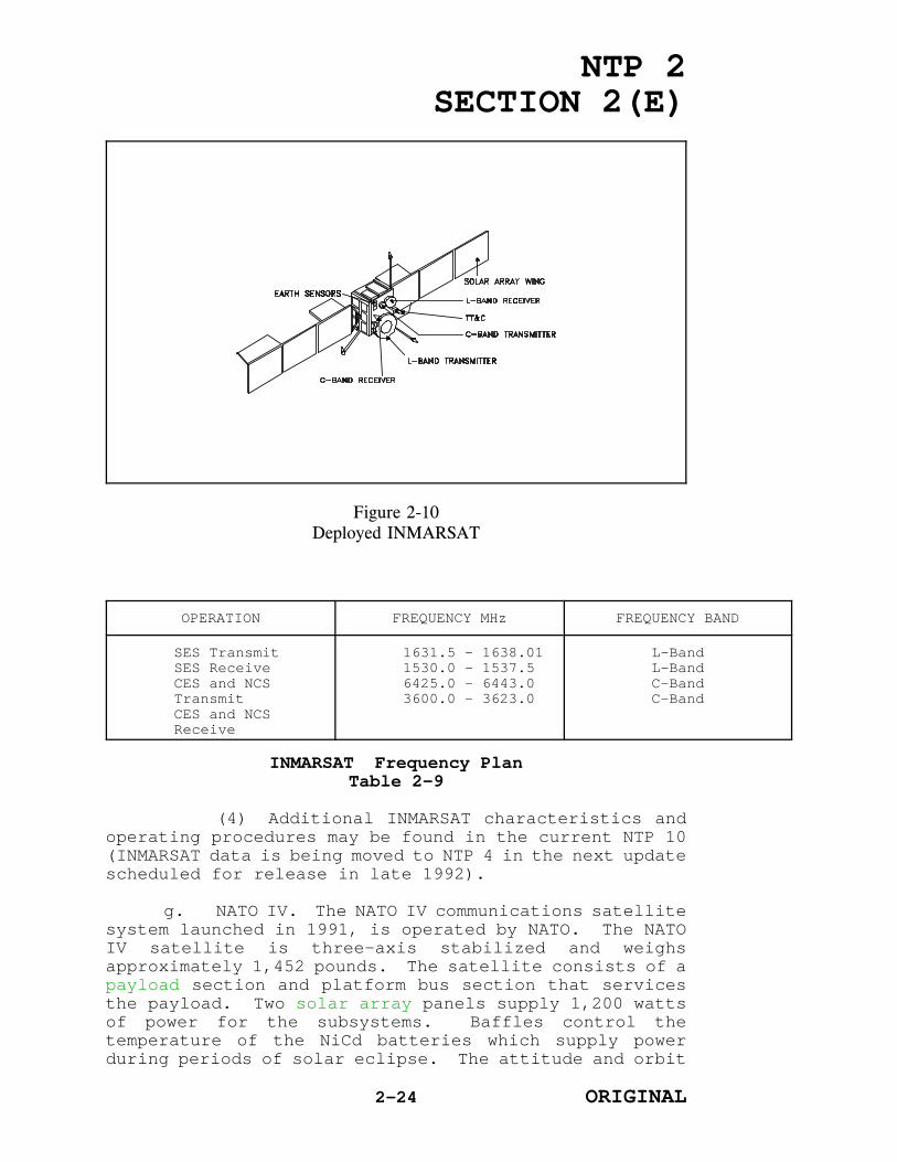
coverage between 76o north and 76o south. Figure 2-10illustrates a deployed INMARSAT.
(3) Frequency Plan. Ship Earth Stations(SES's) transmit and receive signals to and from thesatellite using L-band frequencies. Coast Earth Stations(CES's) and Network Control Stations (NCS's) transmitand receive signals to and from the satellite using C-band frequencies. Table 2-9 lists the operationalfrequencies for the INMARSAT network. SES is alwaystuned to the Common Signaling Channel to listen forassignments. When not engaged in passing traffic, SES isin an idle state.
2-23 ORIGINAL
NTP 2SECTION 2(E)
Figure 2-10Deployed INMARSAT
OPERATION FREQUENCY MHz FREQUENCY BAND
SES TransmitSES ReceiveCES and NCSTransmitCES and NCSReceive
1631.5 - 1638.011530.0 - 1537.56425.0 - 6443.03600.0 - 3623.0
L-BandL-BandC-BandC-Band
INMARSAT Frequency PlanTable 2-9
(4) Additional INMARSAT characteristics andoperating procedures may be found in the current NTP 10(INMARSAT data is being moved to NTP 4 in the next updatescheduled for release in late 1992).
g. NATO IV. The NATO IV communications satellitesystem launched in 1991, is operated by NATO. The NATOIV satellite is three-axis stabilized and weighsapproximately 1,452 pounds. The satellite consists of apayload section and platform bus section that servicesthe payload. Two solar array panels supply 1,200 wattsof power for the subsystems. Baffles control thetemperature of the NiCd batteries which supply powerduring periods of solar eclipse. The attitude and orbit
2-24 ORIGINAL

NTP 2SECTION 2(E)
control subsystems use sun sensor and infrared earthsensors to maintain orbit position. The TT&C ismonitored and controlled by the TT&C ground station atOakhanger, United Kingdom. Design life is seven years.
(1) The NATO IV satellite providescommunications in the SHF and UHF bands. The SHFtransponder provides four channels, and the UHFtransponder provides two channels. The NATO IVcharacteristics are listed in table 2-10.
TRANSPONDER FREQUENCYBAND
CHANNEL ANTENNA EIRP BANDWIDTH
SHF7.25 - 8.4GHz
1234
EarthCoverageNarrowBeamWide BeamSpot Beam
31 dBW34 dBW35 dBW39 dBW
135 MHz85 MHz60 MHz60 MHz
UHF
Uplink:250 - 260 MHz
Downlink:305 - 315 MHz
1
2
EarthCoverage
EarthCoverage
26 dBW
26 dBW
25 kHz
25 kHz
NATO IV CharacteristicsTable 2-10
(2) The NATO satellite system consists of the24 active satellite ground terminals (SGT's), two controlcenters, and the NATO school segment. Table 2-11 liststhe NATO SGT's.
F1 Kester, Belgium F13 Izmir, Turkey
F2 Euskirchen, Germany F14 Verona, Italy
F3 Northwest, Virginia F15 Keflavik, Iceland
F4 Oakhanger, UnitedKingdom
F16 Bjerkvik, Norway
F5 Eggemoen, Norway F17 Balado Bridge, UnitedKingdom
F6 Ankara, Turkey F18 Folly Lake, Canada
F7 Civitavecchia, Italy F19 Gibraltar, UnitedKingdom
F8 Carp, Canada F20 Landau, Germany
F9 Schoonhoven, Netherlands F21 Catania, Italy
2-25 ORIGINAL

NTP 2SECTION 2(E)
F10 Lundebakke, Denmark F22 Greenland, Denmark
F11 Atalanti, Greece F25 T1 (Transportable)
F12 Lisbon, Portugal F29 Saxa Vord, UnitedKingdom
NATO TerminalsTable 2-11
h. SKYNET 4. SKYNET 4 is the latest in a seriesof United Kingdom military communication satellites. TheSKYNET 4 system consists of the satellites and variousfixed and transportable ground stations on land and sea.Each satellite is three-axis stabilized in geosynchronousorbit, weighs approximately 1,452 pounds, and consists ofa payload and platform section. The solar array panelssupply 1,200 watts of electrical power at a regulated 42V dc required for the subsystems. Two NiCd batteries, 14cells each, supply power during periods of eclipse. Sunsensors and infrared earth sensors are used for attitudeand orbit control. The TT&C is monitored and controlledfrom the main control center at the Royal U.S. Air ForceStation, Oakhanger, United Kingdom. The antenna arraycontains a variety of UHF and SHF antennas required fordifferent coverage patterns and communications systems.Characteristics of the SKYNET 4 satellite payload arelisted in table 2-12.
TRANSPONDER FREQUENCYBAND
CHANNEL ANTENNA EIRP BANDWIDTH
SHF7.25 - 8.4GHz
1234
EarthCoverageNarrowBeamWide BeamSpot Beam
31 dBW34 dBW35 dBW39 dBW
135 MHz85 MHz60 MHz60 MHz
UHF
Uplink:305 - 315 MHz
Downlink:250 - 260 MHz
1
2
EarthCoverage
EarthCoverage
26 dBW
26 dBW
25 kHz
25 kHz
SKYNET 4 Payload CharacteristicsTable 2-12
2-26 ORIGINAL

NTP 2SECTION 2(E)
203. EARTH SEGMENT
The earth segment of UHF SATCOM consists of the UHFradio terminals (shore, ship-board, airborne, research,development, test and evaluation, and training) developedunder the FLTSATCOM program and a small number ofterminals that were developed during the TacticalSatellite Communications program. The earth segmentincludes the earth terminals located at Naval Computerand Telecommunications Area Master Stations (NCTAMS's)Atlantic (LANT), Mediterranean (MED), Western Pacific(WESTPAC), and Eastern Pacific (EASTPAC); NavalCommunications Stations (NAVCOMMSTA's); and NavalComputer and Telecommunications Stations(NAVCOMTELSTA's). The earth segment also includes thetransmitters, receivers, baseband equipment, andsubsystems which are discussed in the remainder of thischapter.
204. RF TERMINALS
a. AN/FSC-79. The AN/FSC-79 is an SHF SATCOMtransmitter designed to support the fleet satellitebroadcast uplink. The downlink for the fleet broadcastis UHF. Figure 2-11 illustrates the AN/FSC-79 antenna.The terminal operates on a single channel, tunable in 1-kHz increments over a transmitting frequency range of 7.9to 8.4 GHz, at a maximum output of 8,000 watts. TheAN/FSC-79 can simultaneously transmit a spread spectrumcarrier and receive a satellite beacon tracking signal.In the primary operating mode, the time divisionmultiplex (TDM) broadcast is converted by the OM-51A/FRmodem to a spread spectrum signal for transmission on theAN/FSC-79. For most components, redundancy is built intothe AN/FSC-79 to ensure a high level of availability.AN/FSC-79 terminals are installed at all NCTAMS andNAVCOMMSTA Stockton, CA.
2-27 ORIGINAL

NTP 2SECTION 2(E)
Figure 2-11AN/FSC-79 Antenna
b. AN/WSC-5(V) Transceiver Terminal. The AN/WSC-5(V) transceiver provides an eight circuit full-duplexdata operation or six full-duplex and two half-duplex,100-watt channels. Figure 2-12 illustrates the AN/WSC-5(V) communications subsystem block diagram. Twochannels may be used in the frequency modulation (FM)mode. It transmits in the frequency band between 292.2to 311.6 Megahertz (MHz) and receives between 240.5 to270.2 MHz. The AN/WSC-5(V) is also capable ofinterfacing with the UHF Demand Assigned Multiple Access(DAMA) equipment. The antenna and transceiver provideeach channel a nominal EIRP of 27 dBW. Three types ofmodulation schemes are used with the transceiver: FM forvoice; FM for tone group; and differentially encodedphase shift keying (DPSK), using the OM-43A/USC modem for
2-28 ORIGINAL

NTP 2SECTION 2(E)
the fleet broadcast. The transmitted FM voice signal ispre-emphasized to improve the signal-to-noise ratio (SNR)and the received FM voice signal is de-emphasized tocompensate for the applied pre-emphasis.
(1) The transceiver has a 70-MHz
Figure 2-12AN/WSC-5(V) Communications Subsystem Block Diagram
interface for connection to either the OM-43A/USCmodem or the TD-1271B/U multiplexer used in the DAMAsubsystem. Teletype operation with the AN/WSC-5(V) isremotely controlled by the C-11330/WSC-5(V).
(2) An eight-channel AN/WSC-5(V) transceivercapability requires three electrical equipment racks anda control equipment rack. Each NCTAMS (LANT, MED,WESTPAC, and EASTPAC) has two AN/WSC-5(V) transceivers(16-channel capability). NAVCOMMSTA Stockton, CA has anAN/WSC-5(V) with eight-channel capability supportingEASTPAC and two three-channel AN/WSC-5(V)'s supportingthe continental United States.
2-29 ORIGINAL

NTP 2SECTION 2(E)
c. AN/WSC-3(V) Transceiver. The AN/WSC-3(V) isthe U.S. Navy's standard UHF satellite terminal and lineof sight (LOS) transceiver. Figure 2-13 illustratesAN/WSC-3(V) Communications Subsystem Block Diagram. TheAN/WSC-3(V) has several variations as listed intable 2-13, to meet the particular requirements ofsubmarines, surface ships, and landing forces. Severalvariants of the AN/WSC-3(V) have been modified for usewith the DAMA subsystem. The AN/WSC-3(V) can beinstalled in surface platforms, submarines, aircraft, andtransportable shelters, and is used by many NATO andallied countries.
Figure 2-13AN/WSC-3(V) Communications Subsystem Block Diagram
2-30 ORIGINAL

NTP 2SECTION 2(E)
AN/WSC-3 VariationsTable 2-13
(1) The AN/WSC-3(V) is designed for single-channel, half-duplex operations in the 225-400 MHzmilitary UHF band, tunable in 5-kHz (on certain variants)or 25-kHz increments, with 20 preset channels. It can beoperated in either the satellite or LOS mode and can becontrolled locally or remotely. An internal receiverfrequency offset switch allows the operator to select therequired 41-MHz offset receive frequency for FLTSAT andLEASAT operations or the 53.6-MHz offset receive
2-31 ORIGINAL

NTP 2SECTION 2(E)
frequency for GAPFILLER operations.
(2) The transmitter output is 30 watts inamplitude modulation (AM); and 100 watts in FM, PSK,differential phase shift keying (DPSK), or frequencyshift keying (FSK) modes. The AN/WSC-3(V) internal modemprovides modulation and detection of digital signals atdata rates of 75 bps (FSK); and 75, 300, 1200, 2400,4800, or 9600 bps (PSK/DPSK).
d. Transportable Equipment. UHF SATCOM extendsthe mobile forces range of ter-restrial communicationswith improved reliability, speed, and reduced deploymentsetup time for theater, corps, amphibious task force, andtactical air elements. It supports the need to exchangeinformation during training and actual conflicts. Themobile terminals currently being used by naval forcesoperate within the UHF frequency band of 225 to 400 MHz.The type of modulation employed by these terminals iseither AM, FM, FSK, PSK or DPSK. The power output rangesfrom 10 to 100 watts and the data rate ranges from 75 to2400 bps.
(1) AN/TSC-96(V). The AN/TSC-96(V) SATCOMCentral provides terminal and transmission equipment intwo shelters: the OZ-46/TSC-96(V) Radio Set Group in a S-250 shelter which is 2,000 pounds and 281 cubic feet (7'Lx 6.5'W x 6'H) and the OL-188(V)/TSC-96(V) DataProcessing Group in a S-280 shelter which is 7,000 poundsand 654 cubic feet (12.3'L x 7.3'W x 7'H). Both of theseshelters are capable of being transported by cargo truck,helicopter, and aircraft; however, they are not able tooperate during transit. The OZ-46/TSC-96(V) is theLanding Force Transmit and Receive Subsystem terminal ofthe FLTSATCOM system. It consists of three AN/WSC-3(V)transceivers, one AN/SSR-1 receiver, an antenna system,line interface units, and ancillary equipment. TheOZ-46/TSC-96(V) radio group can be remotely operated upto 250 feet from the OL-188(V)/TSC-96(V) processing groupby interconnect cable. The OL-188(V)/TSC-96(V) containsthe voice, data, teletype, and communications security(COMSEC) equipment. The AN/TSC-96(V) is capable ofterminating the 1200 bps fleet broadcast channels and the2400 bps Secure Voice (SECVOX) Subsystem. The AN/TSC-96(V) also has the capability to function as a CommonUser Digital Information Exchange Subsystem (CUDIXS)subscriber. The CV-3333/U Audio Digital Converter and
2-32 ORIGINAL

NTP 2SECTION 2(E)
encryption device can be remotely operated up to 500 feetfrom the OL-188(V)/TSC-96(V) using an external powersource. Power outputs are 100 watts for FM (FSK/PSK)transmission or 30 watts for AM transmission. TheAN/TSC-96(V) requires a line voltage of 208 V alternatingcurrent (ac), 60 Hz, 3 phase; or 115 V ac, 60 Hz, 1phase. The AN/TSC-96(V) normally deploys with organictactical mobile electric power generators for fieldoperations. The AN/TSC-96(V) is intended to be used bythe U.S. Marine Air Ground Task Force Headquarters (MAGTFHQ) element. Table 2-14 lists the equipment for theAN/TSC-96(V) terminal.
(2) AN/VSC-7. The AN/VSC-7 vehicular satelliteterminal is a narrowband, single-channel radio,consisting of the AN/PSC-3 transceiver, a vehicularinstallation kit, and ancillary equipment. The AN/VSC-7equipment can be operated from a vehicular power source.This UHF SATCOM transceiver is used on tactical vehiclesas a NCS in the execution of ground force tacticalmissions.
(3) AN/URC-100 and AN/URC-101 UHF/Very HighFrequency (VHF) Transceiver. The AN/URC-100 and AN/URC-101 transceivers are multi-purpose radios with 8,360channels available in the UHF and VHF bands of 225 to 400MHz and 115 to 150 MHz. The transceivers are designedfor manpack, aircraft, shipboard and vehicle use. Thetransceivers are fully synthesized radios and tune acrossthe total frequency range in increments of 25 kHz.
(a) As a manpack tactical transceiver, theequipment is designated the AN/URC-100, while as a SATCOMtactical transceiver, the equipment is known as theAN/URC-101. Both sets have evolved from the PT-25Aportable emergency transceiver.
(b) Both transceivers are contained inidentical weather resistant manpack-type cases. A remotecontrol head provides for power on/off, volume andsquelch controls, as well as preset frequency selection.Features of the control unit include an electronicfrequency display that indicates the frequency in use,and the ability to load eight preset frequencies into anelectronic memory. There is also a scan mode in whichthe unit automatically scans three operator-presetchannels.
2-33 ORIGINAL

NTP 2SECTION 2(E)
ITEM ITEM NOMENCLATURE QUANTITY
Shelter (OL-188(V)) S-280 1
Shelter (OZ-46) S-250 1
Processor AN/UYK-20(V) 1
Demultiplexer TD-1063A/SSR-1 1
Combiner/Demodulator MD-960/SSR-1 1
Amplifier/Converter AM-6534/AAE-1 1
Distributor-TransmitterTeletypewriter
TT-603/UG 1
Teletypewriter AN/UGC-77 2
Switchboard, ReceiverTransfer
SB-3195(U) 1
Panel, PatchCommunications
SB-3145/UG 1
Teleprinter TT-624(V)/UG 2
ReperforatingTeletypewriter
TT-605/UG 1
Control-Indicator C-9351/WSC-3 4
Control-Indicator C-9899/WSC-3 3
Recorder-Reproducer(magnetic tape cartridge)
AN/USH-26(V) 1
Recorder-Reproducer(perforated tape)
RD-397(V)/U 1
Interconnecting Group ON-143(V)4/USQ 2
Antenna AS-2815/SSR-1 1
Audio DigitalConverter/EncryptionDevice
CV-3333/U 1
AN/TSC-96(V) Terminal EquipmentTable 2-14
2-34 ORIGINAL

NTP 2SECTION 2(E)
(c) All AN/URC transportable radios,with the exception of the AN/URC-110, have been declaredobsolete (ASDC3I letter of 25 June 1989) and will soondisappear from the fleet.
(4) AN/URC-110 Transceiver. The AN/URC-110transceiver is a data transceiver with 5-kHz channelspacing. It operates in the VHF range of 115 to 150 MHzand in the UHF range of 225 to 400 MHz. This manpacktransceiver was designed with a low noise synthesizer topermit operation with tactical modems such as theMotorola PM-15A.
(a) The 5-kHz channel spacing providesthe transceiver with 35,000 UHF and 6,800 VHF channels.The unit can transmit data and has LOS and SATCOMcapabilities. The modular construction enables the userto configure the unit to support a variety of missionneeds.
(b) Like the AN/URC-101, thistransceiver is fully synthesized, has 20 watts of powerfor SATCOM operation and can function as a repeater andfrequency translator for users requiring extended rangecommunications.
(5) AN/PSC-3 Manpack. This satelliteterminal is a tactical UHF-FM radio which permits two-waycommunications in satellite and LOS modes. It is capableof FM voice and 300-2400 bps data communications in half-duplex synchronous and burst data communications usingthe AFSATCOM I transponder on the FLTSAT. The AN/PSC-3operates in the 225 to 399.995 MHz frequency range,features FM and PSK modulation, with 5-kHz channels inthe satellite mode and 25-kHz channels in the LOS mode.Power outputs are 35 watts in the satellite mode with aterminal EIRP of 21.4 dBW using an ancillary antenna or2 watts for LOS mode. The AN/PSC-3 uses a self-containedbattery powerpack and weighs approximately 30 pounds withthe battery powerpack. The AN/PSC-3 is intended to allowcommunications between the landing force commander'sremote mobile tactical units and selected aircraft.
(6) LST-5B/C. The LST-5B and LST-5Clightweight (less than 20 pounds) UHF SATCOM terminals
2-34 ORIGINAL
NTP 2SECTION 2(E)
are used for LOS and SATCOM on 5-kHz or 25-kHz bandwidthchannels, tunable in 5-kHz increments. They are used formanpack, vehicular, or fixed station applications. Theradio sets operate in the 225 to 400 MHz frequency rangeand are suitable for voice or data communications at datarates of 1200 or 2400 bps. These sets are also capableof operating in wideband modes in AM or FM voice andcipher text.
e. AN/SSR-1 and AN/SSR-1A Receivers. The AN/SSR-1 and AN/SSR-1A Satellite Signal Receiving sets provideU.S. Navy surface ships with the capability of receivingthe UHF Fleet Satellite Broadcast. The satellite receiveraccepts RF signals between 249 and 259 MHz, with amodulation bandwidth of 25 kHz. The signal may be eitherFM or PSK and the receiver set has a manual switch forselecting the applicable demodulation mode. TheTD-1063/SSR-1 receiver is capable of driving high-levelteletypewriters and the TD-1063A/SSR-1A is capable ofdriving both high- and low-level teletypewriters. Thesystem components include up to four AS-2815/SSR-1antennas and their respective AM-6534/SSR-1 amplifier-converters, an MD-900/SSR-1 combiner-demodulator, and aTD-1063/SSR-1 or TD-1063A/SSR-1A demultiplexer. The AS-2815/SSR-1 receiver set antennas may be replaced by amodified OE-82C/WSC-1(V) at times when additional antennagain is required.
(1) The four topside AS-2815/SSR-1 antennalocations provide overlapping 360o receive capability.The designed operating range of the antennas is 240 to259 MHz. The antenna polarization is right-hand circularwith a hemispherical pattern. Each antenna receives RFinput which is processed by its associated amplifier-converter. The amplifier-converter improves the RFsignal received at the antenna by amplifying it to ausable level and converting the signal to an intermediatefrequency (IF) for relay to the combiner-demodulator.The receiver set combines each antenna signal to obtainthe best signal. When multiple antennas receive the RFinput, the receive technique results in an improved SNR.
(2) The combiner-demodulator demodulates theIF signal from the amplifier-converter. In FM operation,it supplies a 300 to 3400 Hz audio signal to the audiopatch panel, where it is then directed to the AN/UCC-1Telegraph Terminal. In PSK operation, it supplies a 1200bps data stream to the demultiplexer. The 1200 bps data
2-35 ORIGINAL

NTP 2SECTION 2(E)
stream accepted by the demultiplexer is output as 15slots of data at 75 bps. The demultiplexer operates inthe PSK mode only. After decryption, the demultiplexeroutput is patched to teletypewriters or processors (NavalModular Automated Communications System (NAVMACS) orTactical Intelligence Subsystem (TACINTEL)), asappropriate.
205. PRIMARY UHF ANTENNA SUBSYSTEMS
a. Antenna Groups OE-82B/WSC-1(V) and OE-82C/WSC-1(V). These devices were designed for shipboardinstallations and interface with the AN/WSC-3(V)transceivers. Figures 2-14 and 2-15 illustrate an OE-82B/WSC-1(V) antenna and OE-82C/WSC-1(V) antenna,respectively. Each configuration consists of an antenna,band pass amplifier-filter, switching unit, and antennacontrol. One or two antennas may be installed providinga view of the satellite at all times. The antennarotates through 360o of azimuth and elevations from nearhorizontal to approximately 20o beyond zenith (elevationangles from +2o to +110o). The antenna is capable ofautomatically tracking in azimuth and requires manualelevation adjustments. The frequency range is between248 and 272 MHz for receive and 292 and 312 MHz fortransmit. The OE-82C/WSC-1(V) antenna is polarizedright-hand circular for transmit and receive. Theantenna can be used in conjunction with the AS-2815/SSR-1receiving antennas and the AN/SSR-1 satellite receivingset. The OE-82B/WSC-1(V) and OE-82C/WSC-1(V) antennasprovide a nominal gain of 12 dB for transmit and 11 dBfor receive.
2-36 ORIGINAL

NTP 2SECTION 2(E)
Figure 2-14OE-82B/WSC-1(V) Antenna Group
b. Shore Station Antenna AN/WSC-5(V). Theantenna, designed for shore installation, comprises fourOE-82A/WSC-1(V) backplane assemblies and is used inconjunction with the AN/WSC-5(V) transceiver. Theantenna does not have automatic tracking capabilities andmust be manually oriented for satellite azimuth andelevation angles. Once the satellite is acquired,locking devices permit antenna stability in order tomaintain maximum signal strength. The antenna providescoverage through 360o of azimuth and for elevation to110o above the horizon. The antenna transmit and receivepolarization is right-hand circular and provides anominal gain of 15 dB for transmit and 18 dB for receive.
2-37 ORIGINAL

NTP 2SECTION 2(E)
The transmit frequency range is 292 to 312 MHz and the
Figure 2-15OE-82C/WSC-1(V) Antenna Group
receive frequency range is 248 to 272 MHz. Figure 2-16illustrates the AN/WSC-5(V) shore station antenna.
2-38 ORIGINAL

NTP 2SECTION 2(E)
Figure 2-16AN/WSC-5(V) Shore Station Antenna
2-39 ORIGINAL

NTP 2SECTION 2(E)
c. Rekey HR9NP Antenna. Installed at variousshore sites, the HR9NP antenna is used for reception offleet broadcast transmissions and subsequent rekey via ahigh frequency (HF) medium. The nine-turn helicalantenna with a 48-inch ground plane is pedestal mountedand manually adjusted in azimuth and elevation. Lockingdevices permit antenna stability to maintain optimumsignal strength. The antenna uses right-hand circularpolarization and operates in the 215 to 260 MHz frequencyrange. The HR9NP rekey antenna provides a nominal gainof 13 dB. Figure 2-17 illustrates a HR9NP antenna.
d. Andrew 58622 Antenna. This device is abifilar, 16-turn helical antenna. The polarization iscircular with gain varying between 11.2 dB and 13.2 dB inthe 240 to 315 MHz frequency band. A 39-inch groundplate is provided and the antenna is approximately 9feet, 7 inches long. It can be manually adjusted forazimuth and elevation look angles. The antenna is usedat various shore installations for transmit and receiveoperations. Figure 2-18 illustrates an Andrew 58622antenna.
2-40 ORIGINAL

NTP 2SECTION 2(E)
e. TACO H-124
Figure 2-17HR9NP Antenna
Antenna. This antennais a 12-turn helix witha 55-inch diameterground plate, mounted ona 4-inch diameter stub.Azimuth and elevationpositioning adjustmentsare manual. Lockingd e v i c e s p r o v i d estability to maintaino r i e n t a t i o n .Polarization is right-hand circular with a 16dB gain at frequenciesfrom 240 to 315 MHz.The swing radius of theantenna is 12 feet. Theantenna is used at shoresites. Figure 2-19illustrates a TACO H-124antenna.
f. TACO H-084Antenna. This shore-
based antenna is an 8-turn helix (13.6-inch diameter)with a 55-inch ground plate, mounted on a 3-inch diameterstub 21.1 inches long. It is manually adjustable in bothazimuth and elevation and locks in position to maintainorientation. Polarization is right-hand circular. Thereis a 13.3 dB gain at frequencies from 240 to 315 MHz.The antenna swing radius is 9 feet, 4 inches. Figure 2-20 illustrates a TACO H-084 antenna.
2-41 ORIGINAL

NTP 2SECTION 2(E)
206. UHF SATCOM SYSTEM
Figure 2-18Andrew 58622 Antenna
The UHF SATCOMsystem consists ofinformation exchangesubsystems that use thesatellites as relays toexchange communicationsdata among shore sites,ships, submarines,aircraft, and mobileunits. Each subsystemis structured to meets p e c i f i c n a v a lc o m m u n i c a t i o n srequirements. Withinthe constraints ofequipment capability,each subsystem addressesthe unique requirementsof the user and theenvironment in which theuser operates. Thefollowing descriptionsare intended to providea basic understanding ofthese subsystems.
a. Fleet Satellite Broadcast Subsystem. The SHF(AJ) Fleet Satellite Broadcast Subsystem provides thecapability to transmit fleet broadcast message traffic ina high-level jamming environment. The subsystem has 15subchannels of encrypted message traffic at an input datarate of 75 bps per channel. Subchannels are TDM andtransmitted in a one-way RF transmission at 1200 bps.The AN/FSC-79 shore terminal transmits data on a directsequence spread-spectrum SHF signal to FLTSAT or LEASATsatellites, where the signal is translated to UHF anddownlinked to the subscribers.
(1) The structure of the fleet broadcasttransmission provides 15 subchannels for general service(GENSER) message traffic, special intelligence (SI)message traffic, and fleet weather data, each operatingat 75 bps. A sixteenth subchannel is used for framesynchronization. GENSER message traffic is entered intothe Naval Communications Processing and Routing System(NAVCOMPARS) processor at the NCTAMS. It can also beinput automatically to the processor when the messagetraffic is received from an Automatic Digital Network
2-42 ORIGINAL

NTP 2SECTION 2(E)(AUTODIN) switching
Figure 2-19TACO H-124 Antenna
center. The samegeneral process isapplicable for enteringSI messages from theSTREAMLINER processor.Fleet weather data isinput directly to thesystem by teletypewritero r a r e c o r d e r -reproducer.
(2) T h eequipment employed inthe receive side of thef l e e t s a t e l l i t ebroadcast is theA N / S S R - 1 A w h i c hreceives, demodulates,and demultiplexes theSATCOM downlink signal.The demultiplexed outputdata stream from thereceiver is decryptedand passed into theNAVMACS or TACINTEL
processors for message screening and printing. Weatherdata is sent directly to teleprinters after decryption.Subscribers that do not have NAVMACS or TACINTELprocessors guard selected fleet satellite broadcastsubchannels and output the data directly to teleprintersor processors. Procedural information related to thefleet satellite broadcast is found in annex A.
b. Officer in Tactical Command InformationExchange Subsystem (OTCIXS). OTCIXS provides a two-waysatellite link (half-duplex mode) to support inter- andintrabattle group over-the-horizon targeting (OTH-T) andC2 communications requirements. OTCIXS passesteletypewriter message traffic and tactical dataprocessor (TDP) formatted data on an automaticallycontrolled time-shared basis over the same OTCIXSsatellite channel. The teletypewriter is used to passtactical C2 information while the TDP is used to exchangeC2, surveillance, and targeting information primarilyamong surface ships and submarines within a battle group.Information can be exchanged between battle groups whenmore than one battle group is operating on the sameOTCIXS channel.
2-43 ORIGINAL

NTP 2SECTION 2(E)
(1) O T C I X S
Figure 2-20TACO H-084 Antenna
operation relies uponthe ON-143(V)6/USQs a t e l l i t e l i n kcontroller. The OTCIXSON-143(V)6/USQ providesautomatic cryptographics y n c h r o n i z a t i o n ,storage, and forwardingof incoming and outgoingteletypewriter and TDPtraffic. It alsocontrols satellite linkaccess.
(2) Controlof transmissions in anOTCIXS network isachieved by a pollingand controlled-accessprotocol resident in theOTCIXS satellite linkcontroller. OTCIXSoperates in a half-duplex mode at a datarate of 2400 or 4800bps. Procedural information related to OTCIXS is foundin annex B.
c. Tactical Data Information Exchange SubsystemA (TADIXS A). TADIXS A is designed to support thebroadcast of OTH-T information from shore to afloat TDPcomputer systems, which support naval warfare operations.
(1) TADIXS A provides integrated worldwideone-way broadcast connectivity supporting naval warfare,using both dedicated terrestrial connectivity andsatellite links. The shore user systems interface viaterrestrial connectivity or SATCOM connectivity with theRF assets located at the four NCTAMS and at NAVCOMMSTAStockton, CA.
(2) Each TADIXS A network must have a NetControl Station (NECOS), normally the TADIXS A gateway;however, any subscriber in the network capable oftransmission is capable of performing the NECOS function.The NECOS grants permission to transmit data to onesubscriber at a time. Each subscriber in the TADIXS Anetwork has a unique subscriber identification (SID)number recognized by the subscriber processor. The SID
2-44 ORIGINAL

NTP 2SECTION 2(E)
serves as the initial basis upon which incoming messagetraffic is screened. Procedural information related toTADIXS A is found in annex B.
d. CUDIXS/NAVMACS. CUDIXS is a shore-basedsystem of processors and peripheral equipment thatenables link control of the SATCOM RF network and messagetraffic processing. NAVMACS has similar equipment atafloat subscriber terminals, and conforms to the CUDIXSlink-control protocol to process message traffic.Collectively, CUDIXS/ NAVMACS provides enhanced ship-to-shore and shore-to-ship communications that featureincreased message traffic volume throughput and improvedlink reliability. The structure of CUDIXS link controlsupports a network membership of 60 special subscriberswithin each network.
(1) The primary relay point ashore formessage traffic to be transmitted or received on theCUDIXS/NAVMACS RF link is the NAVCOMPARS. Messagetraffic for transmission on the CUDIXS link can beinput to NAVCOMPARS by over-the-counter facilities atthe NCTAMS's. Message traffic that originates from otherlocations is delivered to the NAVCOMPARS processor byAUTODIN or other NAVCOMPARS termination links.
(2) Message traffic received by NAVMACSafloat is output to peripheral equipment or to messageprocessors. Each active subscriber to a CUDIXS net isassigned a SID, by a CUDIXS NECOS, for recognition by theNAVMACS terminals. Additional information related toCUDIXS/NAVMACS is found in annex C.
e. TACINTEL. The TACINTEL subsystem AN/USQ-64(V)7 is one of the battle force information managementsystems and is used for the transmission of SIcommunications. The present system is a 2400/4800 baud,netted, computerized DAMA communications link thatenables receipt and transmission of message traffic viaUHF satellites using DAMA-equipped channels. A pollingscheme supports a net membership of up to 23 shipboardterminals and a shore TACINTEL Link Control Facilitywithin a satellite footprint. A DAMA slot of one UHF 25-kHz channel has been allocated for TACINTEL on variousFLTSATCOM satellites. The shipboard terminal is used forhandling TACINTEL message traffic as well as screening upto a maximum of two channels of the fleet satellitebroadcast. Procedural information related to TACINTEL isfound in the classified annex D, which is publishedseparately.
2-45 ORIGINAL

NTP 2SECTION 2(E)
f. UHF DAMA Subsystem. The UHF DAMA subsystemprovides users with increased communication capacity andreliability over dedicated access on the FLTSAT andLEASAT satellites. The additional capacity is providedby the multiple access feature of DAMA. Increasedreliability is provided by the application of forwarderror correction (FEC) and data interleaving techniques.The heart of the UHF DAMA subsystem is the TD-1271B/U TDMwhich is capable of multiplexing many combinations ofSECVOX, teletypewriter, and data subsystems onto a single25-kHz UHF satellite channel, permitting increased use ofthe channel. DAMA output data is organized into frameformat, each containing a strictly defined sequence oftime intervals (time slots). The large number ofavailable frame formats permits reallocation of assets tomeet dynamic tactical requirements while continuing toprovide service to long-term dedicated users. Proceduralinformation related to DAMA is found in annex E.
g. Submarine Satellite Information ExchangeSubsystem (SSIXS). SSIXS was planned to augment very lowfrequency (VLF) and low frequency (LF)/medium frequency(MF)/ HF communication links between shore-basedsubmarine Broadcast Control Authorities (BCA's) andsubmarines. SSIXS provides the submarine commander withthe means to receive Group Broadcast messages transmittedat scheduled times via the satellite. Submarines maytransmit a request (Query/Response mode) for any messagesheld in queue to the BCA between Group Broadcasts. Theshore terminal responds to these requests withacknowledgments for individual messages just received,and transmits all messages held for the queryingsubmarine. The availability of the two modes ofoperation, Group Broadcast and Query/Response, permitsthe submarine commander the choice of being active orpassive at his discretion. A 25-kHz channel on FLTSATand/or LEASAT satellites has been allotted to SSIXS. ASSIXS network may have up to 120 submarine subscribersand may be established on more than one satellitechannel. Two BCA's may share a single satellite channelby offsetting the time of their respective GroupBroadcast transmissions.
(1) SSIXS shore sites have received a majorupgrade referred to as SSIXS II. The submarine SSIXSterminal remains the same. Procedural informationrelated to SSIXS is found in annex F.
(2) The SSIXS II baseband equipment installedat the BCA locations ashore serves the following
2-46 ORIGINAL

NTP 2SECTION 2(E)
purposes:
- Accepts messages for delivery tosubmarines via either satellite or VLF paths, andreceives messages from submarines via the satellite forforwarding; and
- Provides the shore SSIXS II operatorwith the capability to compose and control themultichannel VERDIN submarine broadcast through aninterface with the Integrated Submarine AutomatedBroadcast Processing System.
h. SECVOX Subsystems. The SECVOX Subsystemprovides the means for transmission of ship-to-ship,ship-to-shore, and shore-to-ship SECVOX communications.These subsystems have dedicated channels or DAMA timeslots on FLTSAT and/or LEASAT. The AN/USC-43(V)Terminal Set, commonly known as the Advanced NarrowbandDigital Voice Terminal (ANDVT) is a SECVOX and dataterminal for airborne (AIRTERM), land-based (MINTERM),and shipboard (TACTERM) communications networks.Currently, ANDVT is only used for ship-to-shore-to-shipSECVOX; however, AIRTERM and MINTERM versions are neardelivery.
(1) Ship-to-Shore-to-Ship. UHF SATCOM ship-to-shore-to-ship SECVOX communications are providedthrough the use of the Satellite Radio Wireline Interface(SRWI) equipment located at various naval communicationsfacilities ashore. Shipboard ANDVT calls are extended toSecure Telephone Unit, Third Generation (STU-III)equipment ashore through operator interface at the SRWI.The SRWI operator monitors the appropriate SATCOM channelfor incoming ANDVT SECVOX calls from afloat units andextends the calls to STU-III users ashore via publictelephone networks or the Defense Switched Network. TheSRWI operator also has the capability of extending STU-III calls originated ashore to any ANDVT equipped afloatunit monitoring the appropriate SATCOM channel.
(2) Ship-to-Ship. UHF SATCOM ship-to-shipSECVOX communications are provided using ANDVT, orCV3333/KG-36 equipment on either dedicated SATCOMchannels or shared SATCOM DAMA time slots.
i. Fleet Imagery Support Terminal (FIST). FISTprovides tactical and strategic imagery intelligencesupport to national and theater level command authoritiesand to forward-deployed U.S. Navy and Marine Corps
2-47 ORIGINAL

NTP 2SECTION 2(E)
commanders. FIST is installed on aircraft carriers,amphibious command ships, amphibious assault ships, flagconfigured ships, and at shore intelligence centers.FIST imagery is transmitted between shore intelligencecenters, ships, and other remote users through a UHFSATCOM link using KG-84A/KG-30 series encryptiondevices. Secure telephone systems are also used. FISTuses the National Imagery Transmission Format, whichprovides joint service interoperability. Proceduralinformation related to FIST is found in annex G.
j. Tactical Related Applications (TRAP) BroadcastSystem. The TRAP Broadcast system, AN/USC-51(V), is acomputer-based communications system that generates aworldwide UHF broadcast via U.S. Navy UHF SATCOM channelsfor rapid delivery of near-real-time tactical, qualitytargeting information in support of a broad community ofdesignated multi-service users equipped with variationsof the Tactical Receive Equipment (TRE). The TRAPBroadcast system provides the capability to automaticallytransmit locally and remotely generated data via singlepath, dedicated communications links.
(1) As currently deployed, TRAP consists offive single channel systems, four dual channel systems,and one mobile single channel system. The basiccapability of each system is to process and reformat upto three source data inputs, and transmit the dataaccording to operator set criteria in an efficientpacked-binary modulation format on assigned UHFfrequencies. Dual channel sites are positioned withinthe footprint of two satellites and provide inter-footprint relay of data to complete the worldwidenetwork.
(2) The TRAP Broadcast shares a 25-kHz UHFchannel with a primary user, usually fleet SECVOX. Dueto downlink frequency restrictions, the broadcast isoperated only on FLTSAT channels 2-6 and LEASAT channels3-7. TRAP further time-shares these offset channelsbecause two or more nodes are located within eachsatellite footprint. Each TRAP node transmits acombination of report, text, or synchronization dataduring their assigned slot(s) of the broadcast cycle.
(3) TRAP data is afforded wider disseminationto non-TRE equipped users through gateways to the TADIXSA network at selected Ocean Surveillance InformationSystem (OSIS) nodes. The TRAP/TADIXS A gateways receivethe TRAP downlink, convert it into TADIXS A format, and
2-48 ORIGINAL
NTP 2SECTION 2(E)
forward selected data on to units equipped to receiveTADIXS A. Additional information related to TRAP and TREis found in section 207 and classified annex H.
k. Monitoring System. The following monitoringequipment provides for day-to-day management of theFLTSATCOM system by NCTAMS personnel who monitorfrequency plans, channel availability, and powerbalancing. Monitoring equipment can also be used as an aid in troubleshooting during interference situations.
(1) Interim FLTSATCOM Spectrum Monitor(IFSM). The IFSM's installed at NCTAMS and NAVCOMMSTAStockton, CA interface with the AN/WSC-5(V) transceiversto monitor the uplink and downlink frequencies. The IFSMis a real-time signal processing system that uses acomputer to control a Hewlett-Packard spectrum analyzerand a switch/control unit via an interface board locatedin the computer's expansion slot. The IFSM operationalprogram will initialize and run at initial turn-on.There are two modes of operation: manual entry mode andreduced capability mode. Manual entry mode selection isinitiated through keyboard control or optional mousecontrol. The reduced capability mode provides a means tooperate the spectrum analyzer and switch/control unitwhen the computer is not operational.
(2) AN/FSQ-131 SATCOM Signal Analyzer (SSA).Production versions of the AN/FSQ-131 will replace theIFSM at the NCTAMS and will also be installed atNAVCOMTELSTA San Diego, CA. The SSA providessimultaneous monitoring of all U.S. Navy UHF SATCOM RFsignals. The SSA facilitates analysis of radio frequencyinterference (RFI) through spectrum analysis, precisefrequency measurements, demodulation, and recordingof data for later analysis. It allows foridentification of local RFI by isolating and recording the signal for further analysis. The SSAinterfaces with the shore station AN/WSC-5(V)transceiver and the OK-481(V)2/FSC Control Monitor Groupto provide uplink and downlink monitoring. It has aself-contained antenna system and performs self-test andcalibration. The key feature of the SSA is its use ofthe fast Fourier transform technique which allows real-time analysis of the Information Exchange Subsystem andUHF DAMA signals which are not technically possible withthe IFSM. The main functions of the SSA are:
- Display of satellite RF signalspectrum (amplitude versus
2-49 ORIGINAL

NTP 2SECTION 2(E)
frequency),
- Waterfall display of satellite RFsignal spectrum (amplitude versusfrequency versus time),
- Remote display terminal monitoring,
- Modulation verification and display,
- Signal demodulation,
- Display of local RF uplinks and downlinks,
- Display of frequency versus timehistory of any RF signal,
- Downlink EIRP measurements,
- Signal bandwidth measurements,
- Data bit rate measurements,
- Precise frequency measurements,
- Recording of signals for comparisonand analysis,
- Power balance measurements,
- RFI/jammer alarm,
- System calibration of SATCOM links,
- High-speed digital spectrum analysisusing fast Fourier transform,
- Printout of data, and
- Computation of data for analysis.
207. FUTURE DEVELOPMENTS - UHF SATCOM SUBSYSTEMS
Increased demands for satellite access, newtechnological developments, and changes in threat allprovide motivation for modifications to existing SATCOMsubsystems.
a. VERSAmodule Eurocard (VME) Architecture. TheVME architecture consists of VME cards and a VME bus
2-50 ORIGINAL

NTP 2SECTION 2(E)
(chassis) that provides interface with newer technologieswhile maintaining compatibility with old technologies.The VME architecture is currently being implemented anddeveloped by several program sponsors within the U.S.Navy (i.e., NAVMACS II, TACINTEL II, TRE). The VMEdesign allows multiple microprocessors to be housed inone chassis.
(1) The VME chassis contains a standardbackplane interface that facilitates the consolidation ofdata processing and storage. The VME chassis houses theVME cards and provides for RED/BLACK partitioning withinthe chassis.
(2) The universal sizes of VME cards supportthe use of commercial off-the-shelf microprocessor boardsas well as cards designed for specific subsystems. Thefunctions of VME cards will vary according to functionaldesign requirements (i.e., receiver, signalamplification, signal distribution, decoding,demodulation processing, system controller, and embeddedcrypto). VME cards are capable of supporting single ormultiple functions on a single card, depending on thesystem design requirements.
b. TACINTEL II+. The TACINTEL II+ Subsystem willbe a computer-based message communication system enablingautomatic receipt and transmission of SI communicationsfor both ashore and afloat users while remaininginteroperable with the present TACINTEL during thetransition.
(1) Nine different basic message types shallbe supported by TACINTEL II+ with other types and formatsto be identified in support of Integrated SICommunications Architecture requirements. In conjunctionwith the Communication Support System (CSS), options inconfiguring baseband interfaces and the use of up to sixdifferent communications media provides systemflexibility. A TACINTEL II+ subscriber may participatein up to six TACINTEL II+ RF nets with automatic messagerouting between nets. A new TACINTEL II+ equipment suiteis being developed to implement these functions withInitial Operational Capability (IOC) expected in theearly to mid 1990's.
(2) The TACINTEL II+ Subsystem will bedesigned with sufficient flexibility so that future SI
2-51 ORIGINAL

NTP 2SECTION 2(E)
communication requirements can be easily incorporated.TACINTEL II+ will have the capability to receive, route,and transmit messages automatically on a priority basis.The system will be capable of communications via anyrequired media in either net or point-to-pointconfigurations. Communications across any mix of thesemedia shall be possible: UHF LOS, UHF satellite, SHFsatellite, EHF satellite, HF, or landline.
(3) The design of TACINTEL II+ software issuch that data could be automatically switched by CSS todifferent media to provide the most efficient use ofcommunications assets. TACINTEL II+ will be sized sothat the equipment can be installed and used inrestricted areas (vans, aircraft, etc.).
c. High Speed Fleet Broadcast (HSFB). The HSFBmultiplexes individually encrypted broadcast packagesgenerated from multiple user subsystems. These broadcastpackages are multiplexed into a 9600 bps aggregate bitstream used in the satellite transmission and a separate1200 bps bit stream for use in HF. The 9600 bps bitstream will carry a 1200 bps GENSER message broadcast,1200 bps oceanographic/meteorological broadcast, andcapacity for Fleet Commander-in-Chief requirements.Multiplexing permits multiple user subsystems to shareavailable satellite capacity, and at the same time,allows a measure of flexibility in altering subsystem bitrates in response to varying tactical operating needs andenvironments. The addition of FEC to the signalenhances broadcast reliability and quality andprovides for theadditional bandwidth margin necessary toeffectively counter satellite jamming and interference.Transmission is effected through the OM-51A/FR spreadspectrum modem and AN/FSC-79 satellite terminal. Mobileplatforms receive the HSFB via the modified AN/SSR-1ASATCOM receiver. Through the demultiplexing process,information is output in a variety of data rates andpassed to individual cryptographic devices and processorsas required. HSFB IOC is anticipated in 1993. Thesingle integrated satellite broadcast (SISB) has beenincorporated into HSFB. Previously planned SISBcapabilities are now included in HSFB as shown in figure2-21.
d. CUDIXS/NAVMACS II. The phased approach forrehosting the current NAVMACS system on a VME/DTC-2architecture (NAVMACS II) is intended to meet growing
2-52 ORIGINAL

NTP 2SECTION 2(E)
fleet needs by: increasing data rates (4.8, 9.6, and19.2 kbps); modernizing the system based on VMEtechnology; providing large on-line message storage (upto a 2.4 gigabyte disk); and incorporating local areanetwork capabilities.
(1) The integration of CUDIXS/NAVMACS II intothe DAMA subsystem will result in bandwidth conservation,and provide greater flexibility for fleet commanders tomaximize allocation of resources.
(2) The CUDIXS rehost effort consists ofreplacing the AN/UYK-20 computer and most of the currentperipheral devices while allowing execution of theexisting AN/UYK-20 program. This will be accomplishedusing processor boards installed in a VME chassis, aswell as a DTC-2 and associated peripheral devices.Follow-on phases will upgrade the software to enhanceoperations. IOC for the CUDIXS/NAVMACS II is 1992.
e. TADIXS A Phase IV. TADIXS A is beingimplemented in four phases.
(1) In the current Phase III, TADIXS A wasestablished as a dedicated network separate from OTCIXS.In Phase IV, IOC 1992, sophisticated gateways will beinstalled (replacing the interim gateways) to provideenhanced data routing and broadcast capabilities for bothOTCIXS and TADIXS A. Implementation of TADIXS A Phase IVdoes not require any shipboard procedural changes orequipment modifications.
(2) The AN/USQ-64(V)9 TADIXS A GatewayFacility (TGF) will provide integrated worldwideconnectivity among the OTH-T community, using bothterrestrial and satellite links through a series ofcomputer-controlled switching nodes. TGF's will belocated at NCTAMS MED, NCTAMS EASTPAC, NCTAMS WESTPAC,NCTAMS LANT, and NAVCOMMSTA Stockton, CA. All OTCIXS andTADIXS A shore user's ON-143(V)6/USQ interconnectinggroups (IG's) will be modified to conform with AN/USQ-64(V)10 TDP Controller specifications.
2-53 ORIGINAL

NTP 2
SECTION 2(E)
Figure 2-21H
SFB B
lock Diagram
2-54
ORIGINAL

NTP 2SECTION 2(E)
f. OTCIXS II. Presently, OTCIXS is not DAMA-compatible. In conjunction with the implementation ofTADIXS A Phase IV, IOC 1992, new OTCIXS firmware will beinstalled which will be DAMA-compatible. OTCIXS II canbe operated in a DAMA or non-DAMA configuration; however,all users on a particular net must be similarlyconfigured. Communications between OTCIXS and OTCIXS IIusers must be accomplished via the TGF.
g. DAMA
(1) Mini-DAMA integrates the TD-1271B/Umultiplexer and the AN/WSC-3 transceiver into a singleunit, significantly reducing the size and weight of thesystem. Mini-DAMA also supports additional UHFcommunications modes, such as interoperable 5-kHz AirForce time division multiple access (TDMA), 5-kHz U.S.Navy non-TDMA, and UHF LOS communications. Capabilitiesof Mini-DAMA include embedded COMSEC, satellite linkprotocols, and eight ports. Three versions of Mini-DAMAare being developed: the AN/USC-42(V)1 Mini-DAMA forship, submarine, and selected shore installations; theAN/USC-42(V)2 Auto-DAMA for major shore installations(i.e., the NCTAMS's) and major combatants/flagships; andthe AN/USC-42(V)3 Mini-DAMA for aircraft. The AN/USC-42(V)2 is identical to the AN/USC-42(V)1 with theaddition of Auto-DAMA cards. The anticipated IOC formini-DAMA is 1994. Figure 2-22 illustrates a Mini-DAMAconfiguration.
2-55 ORIGINAL

NTP 2SECTION 2(E)
Figure 2-22Mini-DAMA Configuration
(2) DAMA Controller. As more DAMA multi-plexers are developed and fielded, more 25-kHz UHF SATCOMchannels will use DAMA. To effectively manage theincreasing number of DAMA resources, a DAMA controller isbeing developed and fielded in phases. During the firstphase, a DAMA Semi-Automatic Controller, which uses thesemi-automatic control mode of the TD-1271B/U to allocateand control the UHF DAMA subsystem resources will bedeveloped. When the AN/USC-42(V)2 Auto-DAMA (part of theMini-DAMA project) is developed, the DAMA Semi-AutomaticControllers will also be upgraded to support the fullyautomatic DAMA control mode and to support the CSS andCopernicus architecture.
h. TRE. The purpose of TRE is to support OTH-Tfor TOMAHAWK cruise missile weapons firing, targetchanges, and tactical intelligence requirements. TREreceives, decrypts, filters, formats, and distributesincoming TADIXS B broadcast data to TDP's, such as theU.S. Navy Tactical Command Systems Afloat, TOMAHAWKWeapons Control System, Combat Control System MK II,Electronic Warfare Control System, and OSIS BaselineUpgrade.
2-56 ORIGINAL

NTP 2SECTION 2(E)
(1) There are two basic engineeringdevelopmental models of TRE: the AN/USQ-101(V)3installed on ships and the AN/USQ-101(V)4 installed insubmarines and at U.S. Navy shore sites. Both systemproduction models will be fielded using the VME opensystem architecture.
(2) TRE has the capability for simultaneousoperation of up to two TADIXS B broadcast channels andone satellite fleet broadcast channel. TRE has automaticcontrol capabilities to determine allocation of TREresources and processing to minimize manual intervention.Additional information relative to applications of TRE isin classified annex H, which is published separately.The first installations of TRE are scheduled for 1994.
208. BASEBAND EQUIPMENT
a. AN/UYK-20(V) Processor. The AN/UYK-20(V) isa militarized processor designed for small and medium-sized processing applications for shipboard or shorefacilities. CUDIXS, NAVMACS, TACINTEL, and SurveillanceTowed Array Sensor System use the AN/UYK-20(V). TheAN/UYK-20(V) has a 64K (65,536 word) memory (a word is 16bits in length, double-length words of 32 bits can beused). The processor has 16 and 32 bit instruc-tions and8, 16, and 32 bit operands. The main memory cycle timeis 750 nanoseconds and has 16 general registers, a real-time clock, and a non-destructive, read-only memory.There are 16 input and 16 output channels in theprocessor. These input/output (I/O) channels are mixedparallel synchronous and asynchronous, with differentvoltage levels representing "1" and "0".
b. ON-143(V)/USQ Interconnecting Group (IG). TheON-143(V)/USQ IG serves func-tions related to I/Ochannels of the control processor. Equipmentconfigurations vary, depending upon the circuit cardsand modules installed. The ON-143(V)/USQ providesRED/BLACK isolation, synchronization of crypto units,data level conversions, and crypto test signals. It alsoprovides crypto control, satellite link control, andinterfaces baseband subsystem components when used in aAN/USQ-64(V) configuration. The IG has severalvariations, some of which are listed in table 2-15.
2-57 ORIGINAL
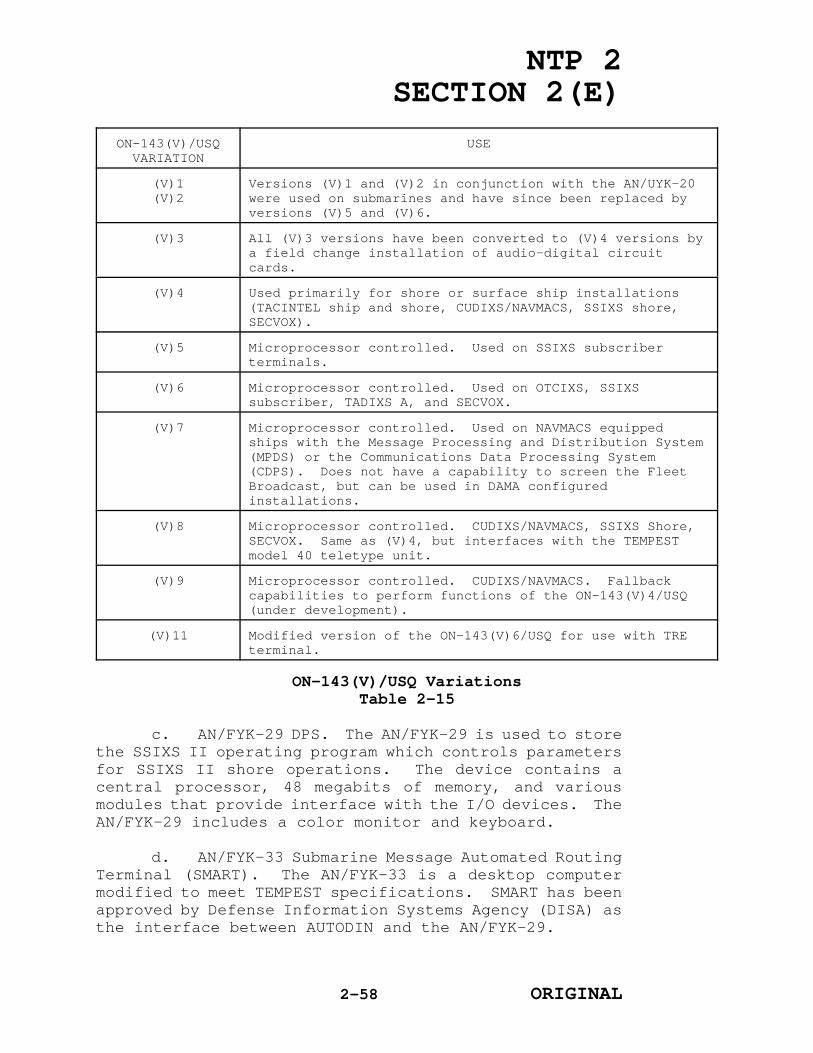
NTP 2SECTION 2(E)
ON-143(V)/USQVARIATION
USE
(V)1(V)2
Versions (V)1 and (V)2 in conjunction with the AN/UYK-20were used on submarines and have since been replaced byversions (V)5 and (V)6.
(V)3 All (V)3 versions have been converted to (V)4 versions bya field change installation of audio-digital circuitcards.
(V)4 Used primarily for shore or surface ship installations(TACINTEL ship and shore, CUDIXS/NAVMACS, SSIXS shore,SECVOX).
(V)5 Microprocessor controlled. Used on SSIXS subscriberterminals.
(V)6 Microprocessor controlled. Used on OTCIXS, SSIXSsubscriber, TADIXS A, and SECVOX.
(V)7 Microprocessor controlled. Used on NAVMACS equippedships with the Message Processing and Distribution System(MPDS) or the Communications Data Processing System(CDPS). Does not have a capability to screen the FleetBroadcast, but can be used in DAMA configuredinstallations.
(V)8 Microprocessor controlled. CUDIXS/NAVMACS, SSIXS Shore,SECVOX. Same as (V)4, but interfaces with the TEMPESTmodel 40 teletype unit.
(V)9 Microprocessor controlled. CUDIXS/NAVMACS. Fallbackcapabilities to perform functions of the ON-143(V)4/USQ(under development).
(V)11 Modified version of the ON-143(V)6/USQ for use with TREterminal.
ON-143(V)/USQ VariationsTable 2-15
c. AN/FYK-29 DPS. The AN/FYK-29 is used to storethe SSIXS II operating program which controls parametersfor SSIXS II shore operations. The device contains acentral processor, 48 megabits of memory, and variousmodules that provide interface with the I/O devices. TheAN/FYK-29 includes a color monitor and keyboard.
d. AN/FYK-33 Submarine Message Automated RoutingTerminal (SMART). The AN/FYK-33 is a desktop computermodified to meet TEMPEST specifications. SMART has beenapproved by Defense Information Systems Agency (DISA) asthe interface between AUTODIN and the AN/FYK-29.
2-58 ORIGINAL

NTP 2SECTION 2(E)
e. AN/UYK-44(V) Data Processing Set (DPS). TheAN/UYK-44(V) is a general purpose computer that has beenmilitarized to provide service in a variety ofapplications. All units of the DPS exchange data andmemory over a common bus, and are called bus users. TheAN/UYK-44(V) has two memory options: Option A allows amaximum of four memory modules that can be any mix of 64Kcore or 256K semiconductor modules up to a maximum of1,048,576 words. Option B allows up to eight 256Ksemiconductor memory modules for a maximum of 2,097,152words.
f. TD-1150/USC TDM. The TD-1150/USC TDM is usedin the Fleet Satellite Broadcast Subsystem. Themultiplexer accepts up to fifteen 75 bps data channelsand multiplexes them into a single 1200 bps output datastream. Primary internal components consist of printedcircuit boards with built-in test capabilities forisolating faults to the card level. The internal clockaccuracy is three parts in 105 over a temperature rangeof 0o to 50oC. The input data interface is MIL-STD-188or MIL-STD-188 low-level. The interface selection ismade by changing input cards. The output interface isMIL-STD-188 low-level which is available in balanced orunbalanced configurations for 1200 bps output.
g. TD-1271B/U TDM. The key component of UHF DAMAis the TD-1271B/U. The TD-1271B/U is both a multiplexerand a modulator/demodulator (modem) which accepts up tofour digital baseband signals at each signal's basebanddata rate. Each signal is stored in a buffer until theappropriate time (determined by the time slot to whichthe signal is assigned). Each signal is then burstthrough the multiplexer's convolutional encoder,interleaver, and modu-lator at the transmission burstrate. Preambles are added prior to modulation. Themodulated signal burst is sent to the transmitter forfrequency translation to the selected UHF terminal fortransmission. The reverse process occurs duringreception; the received signal is demodulated,deinterleaved, decoded, and stored in a buffer at thetransmission burst rate prior to being transferred to thebaseband equipment at the baseband data rate.
(1) Each TD-1271B/U provides four half-duplexI/O ports to interface with baseband equipment. Eachport is capable of transmitting and receiving data atrates of 75, 300, 600, 1200, 2400, 4800, or 16,000 bps.
2-59 ORIGINAL

NTP 2SECTION 2(E)
However, if a port is selected to operate at the 16,000baseband data rate, the other three ports are preemptedfrom operation. The TD-1271B/U multiplexer will normallybe mounted in one of four control-monitor groups: OK-454(V)WSC (Single DAMA), OK-455(V)WSC (Dual DAMA), OK-481(V)2/FSC (Large Shore DAMA), or OW-101/FSC, dependingon the installation platform or site.
(2) A self-test is performed as an integralpart of equipment operation. This test is activatedautomatically by monitored voltage levels or eventswithin selected functions during equipment operation.The test occurs when the I/O ports are inactive,requiring approximately 20 milliseconds to complete.Interface signals between the subscriber unit and theperipheral baseband equipment or subsystems are inaccordance with MIL-STD-188-114.
h. Modulator/Demodulator (Modems)
(1) OM-51A/FR Modem. The OM-51A/FR modem ispart of the Fleet Satellite Broadcast Subsystem. It is aspread spectrum modem, which when used in combinationwith the AN/FSC-79 SATCOM terminal, provides an RFtransmission capability in a high-level jammingenvironment. The purpose of the modem is to provide RFanalog and digital conditioning of circuits and frequencysynthesizing for dual transmission and reception. Themodem interfaces with the AN/FSC-79 terminal and the AM-6543/SSR-1 amplifier-converter. The OM-51A/FRinstallation consists of a standard cabinet with sevenslide-mounted drawer assemblies for the installation ofthe summary control panel, frequency synthesizer,receiver-synchronizer, coder-modulator, demodulator, andtwo power supplies.
(2) OM-43A/USC Modem. The OM-43A/USC is usedwith the AN/WSC-5(V) UHF transceiver at shoreinstallations. It performs DPSK modulation anddemodulation of an input serial digital data stream atselected data rates of 75, 300, 1200, 2400, 4800, and9600 bps. The OM-43A/USC can operate in full-duplex,although the normal operation for FLTSATCOM is half-duplex. The output IF is 70 MHz. The OM-43A/USC modemgroup installation consists of the MD-905A/USC modem anda C-9219A/USC control indicator. The OM-43A/USC can beused as a backup, not using spread spectrum, for theOM-51A/FR modem.
2-60 ORIGINAL
NTP 2SECTION 2(E)
(3) ON-163A/FR Interconnecting IndicatorGroup. The ON-163A/FR is installed with the OM-51A/FRmodem. The group provides a secondary modulation modefor the AN/FSC-79. The equipment contains an OM-43A/USCmodem, a power supply, a UHF and IF patch panel, a datapatch panel, and three units of test equipment. Thepatch panel IF section provides the means to patch theoutput of either the OM-51A/FR or the OM-43A/USC as theuplink signal to the AN/FSC-79 transmitter. The UHFsection has the means to patch a UHF test signal to anon-line AM-6534/SSR-1 down-converter. The data patchpanel provides the means to patch the 1200 bps datastream to the input of the OM-51A/FR or OM-43A/USC. Testequipment consists of a frequency counter, spectrumanalyzer, and UHF signal generator.
i. Display Terminals. Two models of displayterminals are installed for use with CUDIXS, NAVMACS andTACINTEL subsystems. The IP-1187A/USQ-64(V) control-indicator designed for shore baseband equipmentinstallations is used in CUDIXS. The AN/USQ-69(V)alphanumeric digital data display terminal designed forshipboard installations, is used in NAVMACS and TACINTELinstallations aboard ship.
(1) IP-1187/USQ-64(V) and IP-1187A/USQ-64(V)Control-Indicators. The control-indicator has twovariations: The IP-1187A/USQ-64(V) features specialTEMPEST shielding; the IP-1187/USQ-64(V) does not includespecial shielding. Both versions provide half-duplex orfull-duplex I/O to a processor.
(2) The components making up the control-indicator terminal include a keyboard with key encodingelectronics, a cathode-ray tube display and monitor unit,a power supply, and a circuit board with microcontroller,memory, and logic electronics. The keyboard is astandard 118 key separate assembly. It can be located upto five feet from the display unit. (The IP-1187A/USQ-64(V) does not include a remotely located keyboard).Key strokes are encoded into ASCII 7-bit binary codes.The keyboard encodes 96 ASCII characters for transmissionand display. Data organization is based on random accessmemory timesharing between control and display functions.
(3) IP-1660/FSQ Operator Workstation. TheIP-1660/FSQ consists of a monochrome data terminal witha 105-key keyboard. It has the capability to display 24
2-61 ORIGINAL

NTP 2SECTION 2(E)
lines of text in either an 80 or 132 column format, withthe 25th line reserved for status comments. The IP-1660/FSQ is used to process, send, and receive messagesfrom the AN/FYK-29A DPS.
(4) AN/USQ-69(V) Data Terminal Set. TheAN/USQ-69(V) consists of a 15-inch diagonal screenmonitor which can display a 2,000 character page, and akeyboard. Memory is available in two sizes: a 2,000character capacity, one-page capability; and a6,000 character, three-page capability. Memoryoverflows, as a result of computer output which initiatesa computer interrupt or as a result of operator input,initiates an audible alarm. A manual control adjacent tothe keyboard provides the means to adjust the intensityof the displayed page.
(5) The keyboard design complies withapplicable military specifications. Seven special keysinitiate generation of unique 7-bit ASCII characters tothe processor for serial interfaces and as an interruptfor parallel interfaces. The terminal installation doesnot require shock mounting. A power outage of up to oneminute will not result in a loss of display data.
j. Recorders-Reproducers
(1) AN/USH-22(V) Recorder-Reproducer. TheAN/USH-22(V) is a magnetic tape reel-to-reel device. Ithas two servo-controlled direct-drive dc torque motors todrive the tape reels. The AN/USH-22(V) is installed inCUDIXS and TACINTEL terminals at shore stations, and isused for long-term storage of message traffic andrecords. The tape unit includes two assemblies: atransport and a controller. One controller is capable ofhandling up to four tape transports. The tape unit iscompatible with the AN/UYK-20(V) processor.
(2) AN/USH-26(V) Recorder-Reproducer. TheAN/USH-26(V) is used onboard ships equipped with TACINTELand NAVMACS. It responds to processor-generated commandssuch as read/write, tape position, reset functions, andstatus requests. Processor-generated status requestscause the recorder to present a status word or countword. The tape position responses include rewind, spaceblock, or space file. When space block is commanded,the recorderjumps from one gap to the next gap andbypasses the data between. A space file response
2-62 ORIGINAL

NTP 2SECTION 2(E)
involves moving the tape until a file mark is found onit.
(3) RD-397(V)/U Signal Data Recorder-Reproducer. The RD-397(V)/U is employed in equipmentinstallations at CUDIXS, NAVMACS, TACINTEL (ship andshore), and SSIXS shore facilities. This tapeperforator/reader can punch tape at 63.3 characters persecond and reads punched tape at a rate of up to 300characters per second. The device is self-contained tothe extent that it is complete with control logic,buffering, and power supplies. It will accept 5-, 6-, 7-, and 8-level tapes without adjustment, and holds up to1,000 feet of tape on the supply reel. Either paper ormetalized Mylar tape may be used.
(4) AN/USH-23(V) Recorder-Reproducer. TheAN/USH-23(V) is employed at CUDIXS and TACINTEL shoreinstallations and consists of three components: up tothree disk drives; a power supply; and a disk controller.The AN/USH-23(V) has a random access storage capabilityof 48 million bits. The two independent disk drives areseparately housed. One of the two disks is removable andone is fixed.
(5) RP-357/FSQ Reproducer. The RP-357/FSQ isa computer controlled, magnetic tape storage device. Thetape transport reads and writes nine-track ANSI format,phase encoded data at a density of up to 1600 bits perinch. Read and write operations are performed at a tapespeed of 25 inches per second.
k. Teletypewriters. Various teletypewritermodels are used in UHF SATCOM subsystem installations.The particular model used depends on the requirement forsubsystems installed.
(1) AN/UGC-77 Teletypewriter. The AN/UGC-77is a militarized U.S. Navy standard teletypewriter thatcan be portable or fixed. The unit has a standardcommunications keyboard, 72 characters per line,friction-feed synchronous motor, and a 7.42-unit code.Message traffic and operator notes are transmitted andreceived serially by means of a five-level binarypermutation code. The AN/UGC-77 operates at 100 wordsper minute, weighs 59 pounds, and is 10 inches high, 16.5inches wide, and 16 inches deep. Line voltagerequirements are 115 V ac, single phase, 60 Hz.
2-63 ORIGINAL

NTP 2SECTION 2(E)
(2) AN/UGC-136 Teletypewriter. The AN/UGC-136 teletypewriter is a militarized, low-level, automaticsend and receive teleprinter. It has storage, editing,and self-test capabil-ities. The AN/UGC-136 iscontrolled by a microprocessor with an internal solid-state memory and has full message composition and editingcapabilities. It prints data nominally at 120 char-acters per second (1200 bps), can transmit or receive atdata rates of 50 to 2400 bps, and can operate in switch-selectable Baudot or ASCII codes. The message storagemodule has a capacity of 12,288 characters. The AN/UGC-136CX is installed onboard submarines andthe AN/UGC-136BX is installed on surface platforms. Theprimary difference between the AN/UGC-136CX and theAN/UGC-136BX is the AN/UGC-136BX has an LED displayincorporated on the front panel to allow viewing of textfor editing purposes when typed. The keyboard printerweighs approximately 59 pounds, is 8.5 inches high, 15.75inches wide, and 17.4 inches deep. The powerrequirements are 115 V ac, 60 Hz, and 100 watts.
(3) AN/UGC-143(V) Teletypewriter. TheAN/UGC-143(V) U.S. Navy Standard Teletypewriter is afully militarized unit. It features a modular designproviding the compatibility for several differentconfigurations: receive only with or without bulkstorage; send/receive without bulk storage using thekeyboard; or send/receive automatically with bulkstorage. It prints 150 characters per second, tencharacters per inch, six lines per inch and is capable ofstoring 500 kilobytes (250 messages, 2 kilobytes each).The power requirements are 115 V ac, 47-63 Hz, 440 watts,single phase. It weighs 180 pounds.
(4) TT-624(V)5/UG or TT-624(V)6/UGTeleprinter. This teleprinter is used at CUDIXS, NAVMACSand TACINTEL installations. It may be used on-line withthe AN/UYK-20 processor or off-line with tape readers,card equipment, and communications terminals. The devicehas a 64-character set capable of printing at speedsranging from 365 lines per minute for 80 columns, to1,100 lines per minute for 20 columns. It can print upto three additional copies using roll paper and fiveadditional copies using fan-fold paper. The TT-624(V)5/UG is an ITA-2 Baudot printer with a serial MIL-STD-188C interface; the TT-624(V)6/UG is an ASCII printerwith an U.S. Navy Tactical Data System slow parallelinterface. It weighs 270 pounds and requires 115 V ac,
2-64 ORIGINAL

NTP 2SECTION 2(E)
60 Hz, single phase power.
(5) TT-835/U System Console. The TT-835/U isa microprocessor-based teletypewriter communicationsterminal. It is used for system initialization, backupand recovery operations, and provides a record of SSIXSII shore system response and alerts. The keyboardprovides man/machine interface for operator control ofthe SSIXS II shore operational program. The operator canenter parameters when conducting diagnostic or programmedmaintenance testing.
(6) RO-600/U Line Printer. The RO-600/U isa microprocessor-based receive-only printer. It isconnected to the on-line AN/FYK-29 and is used to printincoming or outgoing messages and system reports. Thisdevice is employed in SSIXS II installations.
l. MU-851(V)1/U Magnetic Disk Memory Unit. TheMU-851(V)1/U is a 205 megabytes, removable media,magnetic disk drive. It has the flexibility to becontrolled by any AN/FYK-29 installed in SSIXS II.Selection of the controlling AN/FYK-29 is performed atthe MU-851(V)1/U front panel controls.
2-65 ORIGINAL

NTP 2SECTION 2(E)
CHAPTER 3
NAVY ULTRA HIGH FREQUENCY (UHF)
SATELLITE COMMUNICATIONS (SATCOM) CONTROL
301. GENERAL
The Department of the Navy (DON) is the systemmanager for the Fleet Satellite (FLTSAT), GAPFILLER,Leased Satellite (LEASAT), and UHF Follow-on (UFO)communications systems. As system manager, the DON hasdelegated day-to-day operations to the Chief of NavalOperations (CNO). In performing the duties ofoperational manager, the CNO has further delegated theresponsibility for operational control and management ofthese satellite systems to Commander, Naval Space Command(COMNAVSPACECOM). The CNO has also delegated selectedfunctions to the Commander, Naval Computer andTelecommunications Command (COMNAVCOMTELCOM) who monitorsthe day-to-day control and operation of naval SATCOMassets and system resources to meet the communicationsneeds of naval forces, Department of Defense (DOD), andnon-DOD users. These monitoring functions are supportedby the Naval Computer and Telecommunications Area MasterStations (NCTAMS's).
302. AUTHORITY
Chapter 1 describes the various organizationsproviding direction for use and operations of the FleetSatellite Communications (FLTSATCOM) system. From amongthose organizations, authority for operational control,technical management, and technical direction is asfollows:
a. Operational Control. The Chairman of theJoint Chiefs of Staff (CJCS), under authority of DODDirective 5105.19, provides overall operational guidancefor the Defense Communications System, including theFLTSATCOM system. The Chairman of the Joint Chiefs ofStaff reviews and validates all Integrated SATCOMDatabase (ISDB) requirements and provides direction tothe CNO for control and allocation of UHF resources.
b. Technical Management. The Commander in Chief,U.S. Space Command (USCINCSPACE) is responsible to theChairman of the Joint Chiefs of Staff for maintaining the
3-1 ORIGINAL

NTP 2SECTION 2(E)
health, status, and survivability aspects of the spacesegment. USCINCSPACE plans and executes satellitetracking and stationkeeping, and assists in the planningand integration of satellite systems.
c. Technical Direction. Within the U.S. Navy,COMNAVSPACECOM as the system operational manager, plansand manages day-to-day operations at the system level forthe FLTSATCOM system. Other technical direction includesdesign and development of satellite systems to satisfyvalidated requirements in support of operations by U.S.Navy and non-U.S. Navy users.
303. RESPONSIBILITIES FOR OPERATIONAL MANAGEMENT
a. Joint Communications Satellite Center (JCSC).Within the guidance identified in CJCS Memorandum ofPolicy (MOP) 37, the JCSC (J6Z) supports the Chairman ofthe Joint Chiefs of Staff in carrying out the followingresponsibilities:
(1) Resolves conflicts in resource allocationand implements CJCS direction for all matters relating tomilitary satellite communications (MILSATCOM) allocationin support of contingency operations.
(2) Serves as the DOD focal point for actionrequiring CJCS approval for MILSATCOM operational access.
(3) Serves as the DOD focal point forapportionment of MILSATCOM capacity.
(4) Monitors the health and operationalstatus of MILSATCOM systems.
(5) Assists users in gaining access inemergency situations.
b. USCINCSPACE. This unified commander is theprincipal advocate and advisor to the Chairman of theJoint Chiefs of Staff for MILSATCOM systems in support ofCommander in Chief (CINC) requirements. In thiscapacity, USCINCSPACE plans for and executes activitiesin support of the health, status, and survivability ofthe space segment, as well as the tracking,stationkeeping, ephemeris data generation and spacecraftcontrol. At the direction of the Chairman of the JointChiefs of Staff, USCINCSPACE provides payload control,assesses the impact of proposed satellite movements, and
3-2 ORIGINAL

NTP 2SECTION 2(E)
executes those movements.
c. CNO. Acting for the DON in the role of systemmanager, CNO exercises overall operational management ofFLTSAT, GAPFILLER, LEASAT, and UFO resources. Systemmanagement includes implementation of assigned MILSATCOMsystems; developing architecture, interoperabilitystandards and system requirements; preparing programs andbudgets and identifying shortfalls; maintaining systemprogram plans; and advocating the need for systemssupporting the DOD SATCOM architecture and CINC.
d. Commandant of the Marine Corps (CMC). The CMCexercises overall management and validation authority forU.S. Marine Corps UHF SATCOM requirements, and forwardsall requirements to CNO for authorization to accessFLTSATCOM resources.
e. COMNAVSPACECOM. As the system operationalmanager, COMNAVSPACECOM is responsible for day-to-dayoperational control and management of the FLTSAT,GAPFILLER, LEASAT, and UFO satellites, with theadditional responsibility of the effective operation andmaintenance of assigned U.S. Navy resources for theDepartment of Defense. As the Navy component ofUSCINCSPACE, NAVSPACECOM executes operational control(OPCON) of assigned resources by performing the followingfunctions:
(1) Plan for and execute the health, statusand survivability aspects of the space segment.
(2) Plan for and execute tracking,stationkeeping, and ephemeris generation (in cooperationwith Air Force Space Command).
(3) Provide spacecraft control after asatellite is declared operational.
(4) Provide communications payload control.
(5) Support the operation of the appropriatesatellite C2 operations centers.
(6) Plan for constellation protection,defense, and reconstitution.
(7) Assess the impact of satellite moves.
(8) Execute satellite moves.
3-3 ORIGINAL

NTP 2SECTION 2(E)
f. COMNAVCOMTELCOM. COMNAVCOMTELCOM is thecommunications manager for assigned UHF SATCOM resources.As such, the commander is responsible for communicationsconnectivity for the fleet. COMNAVCOMTELCOM personnel(at the NCTAMS) act on behalf of the FLTCINC's to manageSATCOM assets allocated to the FLTCINC's. Specifically,COMNAVCOMTELCOM is responsible for:
(1) Day-to-day operational direction andmanagement control of U.S. Navy FLTSATCOM system assetswhich encompasses interface and coordination with othersatellite control agencies;
(2) Establishment of operating procedures andstandards, and monitoring of user and earth terminalperformance;
(3) Consolidation of requests and allocationof resources, in coordination with CNO and FleetCommanders in Chief (FLTCINC's), to meet CJCS validatedrequirements; and
(4) Operational scheduling of the FLTSATCOMsystem to include validated non-U.S. Navy users andvalidated research, development, and testingrequirements.
g. FLTCINC's. The FLTCINC's have authoritativedirection and control of assigned U.S. Navy UHF SATCOMfunctions, including naval broadcasts, ship-to-shore-to-ship, air-to-ground-to-air, and other designated tacticalcommunications requirements within their area ofoperations. Authoritative direction and controlencompasses the direction provided by the FLTCINC's tothe NCTAMS for operational adjustments, or temporarynetwork changes required to support contingencies oremergency situations, to improve the effectiveness ofcommunications services, and to satisfy the operatingrequirements of naval forces.
h. NCTAMS. NCTAMS allocates resources to satisfyoperational requirements of the operating forces asdirected by the FLTCINC. The NCTAMS responds to FLTCINCrequests for information concerning status andutilization of SATCOM capabilities, and responds toFLTCINC direction for the reallocation of capabilities tomeet emergency requirements.
3-4 ORIGINAL

NTP 2SECTION 2(E)
i. Table 3-1 lists the control activitiesresponsible for UHF SATCOM management, including plainlanguage address and Defense Switched Network (DSN)numbers.
3-5 ORIGINAL

NTP 2SECTION 2(E)
AUTHORITY/OPERATIONAL MANAGER
PLAIN LANGUAGE ADDRESS//OFFICESYMBOL// DSN NUMBER
Chairman of the JointChiefs of Staff *
JOINT STAFF WASHINGTON DC//J6Z// 225-3700
USCINCSPACE * USSPACECOM PETERSON AFB CO//SPJ305//
692-5770
CNO * CNO WASHINGTON DC//943// 225-1340
CMC * CMC WASHINGTON DC//C4I2/CCT// 223-3135
COMNAVSPACECOM * COMNAVSPACECOM DAHLGRENVA//N31//NAVSPOC DAHLGREN VA 24 HR
249-7873
249-7771
COMNAVCOMTELCOM *
COMNAVCOMTELCOM WASHINGTON DC//N32//
292-2600
CINCLANTFLT * CINCLANTFLT NORFOLK VA//N6// 934-5214
CINCPACFLT * CINCPACFLT PEARL HARBOR HI//N5// (315) 474-5877
CINCUSNAVEUR * CINCUSNAVEUR LONDON UK//N611// (314) 235-4182
NCTAMS LANT NCTAMS LANT NORFOLK VA//N525// 564-4182
NCTAMS MED NCTAMS MED NAPLES IT//N62// (314) 625-6426
NCTAMS EASTPAC NCTAMS EASTPAC HONOLULU HI//N34// (315) 453-0118
NCTAMS WESTPAC NCTAMS WESTPAC GQ//N81// (315) 355-5260
* Manned during normal working hours only.
U.S. Navy UHF SATCOM Control ActivitiesTable 3-1
3-6 ORIGINAL

NTP 2SECTION 2(E)
304. SYSTEM CONTROL
a. The FLTSATCOM system control segment performsthe functions of spacecraft and payload control.Telemetry, tracking, and command (TT&C) functions for theFLTSATCOM system are shared responsibilities ofcommercial contractors and military elements of theDepartment of Defense. Figure 3-1 illustrates theresponsibilities of contractors and Department of Defensefor control of the FLTSATCOM system.
Figure 3-1FLTSATCOM Control System
3-7 ORIGINAL

NTP 2SECTION 2(E)
b. U.S. Air Force Consolidated Space OperationsCenter (CSOC). The control segment of the FLTSAT and UFOsatellites provides stationkeeping tasks such as TT&C.These functions are assigned to the Air Force SatelliteControl Network (AFSCN). A detachment of U.S. Navypersonnel is stationed at the CSOC at Falcon AFB, CO toassist in the coordination of FLTSATCOM operations amongthe Services. A capability for transmitting selectedcontrol commands to the spacecraft is available throughRemote Tracking Stations (RTS's) worldwide.
c. FLTSATCOM Contractor-operated Facilities.Hughes Communications Services, Incorporated (HCSI) andCommunications Satellite (COMSAT) General providespacecraft support as coordinated by COMNAVSPACECOM.
d. LEASAT TT&C
(1) The LEASAT TT&C subsystem is technicallycontrolled and monitored by the lessor, HCSI as directedby CNO. HCSI TT&C elements include the Contractor'sOperations Control Center (COCC) at El Segundo, CA,Contractor Satellite Control Stations (CSCS's) co-locatedwith the Government Satellite Control Stations (GSCS's)at NCTAMS Eastern Pacific (EASTPAC) Honolulu, HI; NCTAMSWestern Pacific (WESTPAC) Guam; NCTAMS Atlantic (LANT)Norfolk, VA; NCTAMS Mediterranean (MED) Naples, Italy;Naval Communications Station (NAVCOMMSTA) Stockton, CA;and Movable Ground Stations (MGS's) at NCTAMS WESTPAC andLANT.
(2) Management responsibility for governmentTT&C functions has been assigned to COMNAVSPACECOM.Management responsibility for operation and maintenanceof TT&C uplink transmission equipment (e.g., AN/FSC-79,OM-51A modem) is assigned to COMNAVCOMTELCOM. Governmentresponsibilities are accomplished through the controlorganization which includes the NAVSPACECOM OperationsCenter (NAVSPOC) and Naval Computer andTelecommunications Command Operations Center (NCTCOC),GSCS's located at the four NCTAMS and NAVCOMMSTAStockton, CA. A U.S. Navy official at each GSCS isdesignated as the Contracting Officer's TechnicalRepresentative (COTR), and will in the event thatCOMNAVSPACECOM is not able to initiate required action,be authorized to direct the contractor to initiatecommands affecting the configuration of thecommunications payload of the satellite. The LEASAT TT&Ccontrol organization is illustrated in figure 3-1.
3-8 ORIGINAL
NTP 2SECTION 2(E)
(3) All spacecraft commands are structuredand coded by HCSI, transmitted by the COCC through theCSCS to the GSCS and uplinked at X-band through a U.S.Navy AN/FSC-79 terminal. No commands will be transmittedto the spacecraft via other than this primary mode unlessauthorized by COMNAVSPACECOM.
(4) All commands which affect thecommunications payload will be in response toCOMNAVSPACECOM direction except in emergency situationswherein immediate action must be taken by HCSI to protectsatellite health. COCC will notify COMNAVSPACECOM withinone hour of all emergency commands transmitted to thespacecraft.
(5) COCC messages requesting U.S. Navyconcurrence for non-catastrophic unscheduled commands(normal scheduled commands are contained in thecontractor monthly satellite technical performancemeasurement report) to the satellite will be sent toCOMNAV-SPACECOM for action via the NAVSPOC/NCTCOC/COCCLEASAT coordination circuit.
(6) NAVCOMTELCOM requests for satellitereconfiguration of the communications payload orrepositioning, etc. will be sent to COMNAVSPACECOM viathe NCTCOC/NAVSPOC coordination circuit for action.
(7) COMNAVSPACECOM response to requests forunscheduled commands, communications payloadreconfigurations or repositioning, etc., will be sent viathe NAVSPOC/NCTCOC/COCC LEASAT coordination circuit.
(8) All satellite command requests/approvalmessages exchanged between HCSI and COMNAVSPACECOMconcerning spacecraft commanding shall be confirmed viatelephone after transmission via the LEASAT coordinationcircuit.
(9) Telemetry monitoring and trackingfunctions are also accomplished through the U.S. NavyAN/FSC-79 terminal, GSCS and CSCS. Telemetry informationprocessing is conducted primarily at the COCC, withappropriate data provided to the government in a monthlysummary.
e. The GAPFILLER satellite control function isperformed by COMSAT General under the direction of CNO.The satellite control function includes the TT&Cfacilities at worldwide COMSAT earth stations, the COMSAT
3-9 ORIGINAL

NTP 2SECTION 2(E)
Control Center in Washington, D.C., and the COMSATlaboratories located in Clarksburg, MD.
f. UHF Follow-On (UFO)
(1) The UHF payload consists of twenty-one 5-kHz channels, seventeen 25-kHz channels and one SHFuplink channel. UFO satellites 1 through 3 interfacewith the TT&C segment through the AFSCN and a NavySatellite Control Network (NSCN).
(2) The UFO TT&C ground systems include allequipment and software that currently exists forFLTSATCOM TT&C, including UFO mission unique software(MUS). Satellite control resides with the CSOC usingAFSCN with its globally dispersed RTS's and through theNSCS employing the ground equipment at the NCTAMS's. TheAFSCN provides full TT&C operations from launch throughpre-operation checkout, telemetry reception, andalternate command and ranging during normal satelliteoperations. Implementation of satellite control, similarto that of FLTSATCOM, includes AFSCN personnel trainingat the contractor's facility, verification of softwarecompatibility using AFSCN CSOC resources, directsatellite to AFSCN TT&C tests, and continuing maintenancevia the AFSCN to contractor interface. The NSCS employsthe existing AN/FSC-79 antenna and OM-51A modem groundprocessors operated at the same NCTAMS that controls thecurrent LEASAT constellation, and provides the primarycommand and ranging radio frequency (RF) interface duringnormal operations.
(3) The TT&C subsystem provides the groundinterface and data processing for satellite TT&C servicesvia: S-band RF, SHF RF interface, or digital equipment.The S-band RF equipment consists of redundant space-ground link system (SGLS) transponders, dual omni-logconical spiral antenna, and other associated hardware(diplexers, filters, switches, etc.). The SGLS equipmentprovides full TT&C operations with the AFSCN duringlaunch, orbit injection and pre-operation on-orbitcheckout and during the operational mission phase,telemetry data and an alternate command and ranging RFinterface. The SHF RF interface equipment, along withthe MD-942 processor, provide the interface with theNSCS's for secure, antijam satellite command and ranging.The digital equipment consists of redundant commanddecoders, telemetry encoders and other associatedhardware. The command decoders process commands fromeither SHF or SGLS uplink channels and provide internal
3-10 ORIGINAL
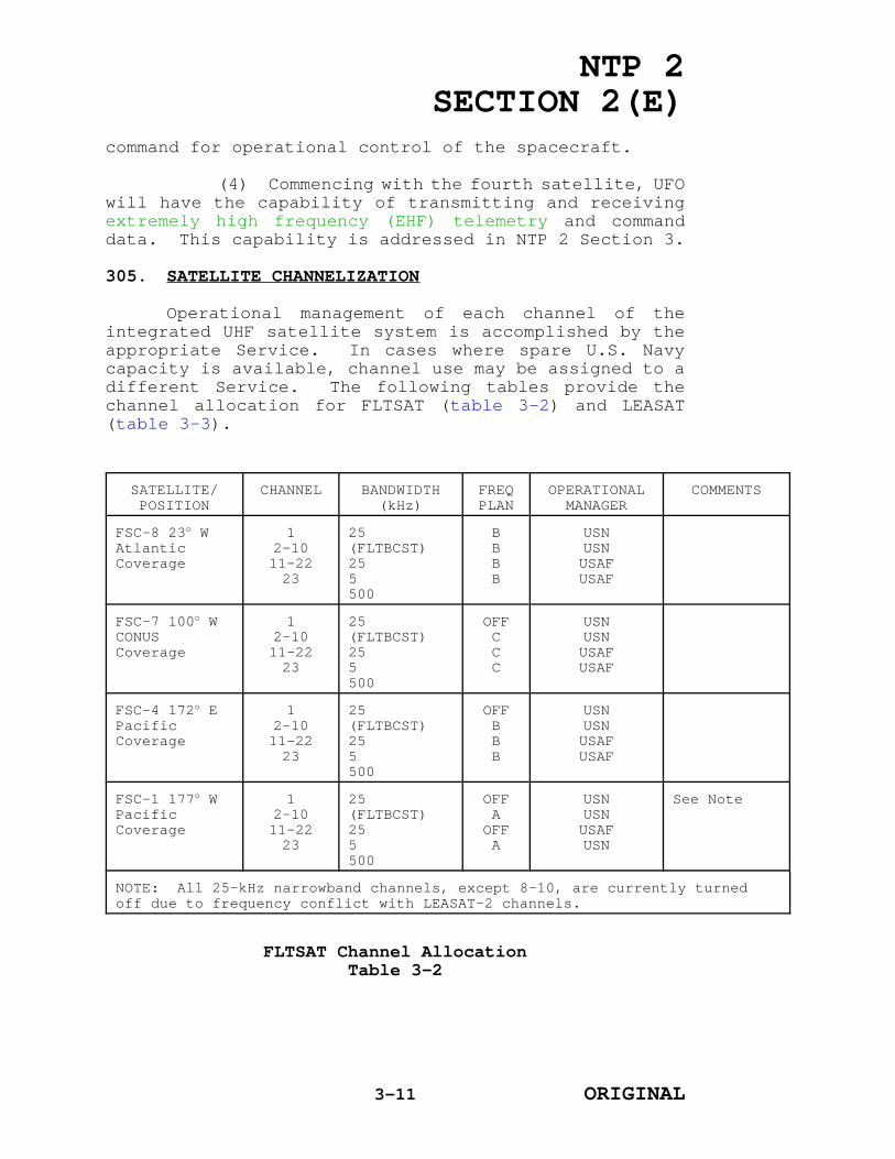
NTP 2SECTION 2(E)
command for operational control of the spacecraft.
(4) Commencing with the fourth satellite, UFOwill have the capability of transmitting and receivingextremely high frequency (EHF) telemetry and commanddata. This capability is addressed in NTP 2 Section 3.
305. SATELLITE CHANNELIZATION
Operational management of each channel of theintegrated UHF satellite system is accomplished by theappropriate Service. In cases where spare U.S. Navycapacity is available, channel use may be assigned to adifferent Service. The following tables provide thechannel allocation for FLTSAT (table 3-2) and LEASAT(table 3-3).
SATELLITE/POSITION
CHANNEL BANDWIDTH(kHz)
FREQPLAN
OPERATIONALMANAGER
COMMENTS
FSC-8 23o W AtlanticCoverage
12-1011-2223
25(FLTBCST)255500
BBBB
USNUSNUSAFUSAF
FSC-7 100o WCONUSCoverage
12-1011-2223
25(FLTBCST)255500
OFFCCC
USNUSNUSAFUSAF
FSC-4 172o E PacificCoverage
12-1011-2223
25(FLTBCST)255500
OFFBBB
USNUSNUSAFUSAF
FSC-1 177o WPacificCoverage
12-1011-2223
25(FLTBCST)255500
OFFA
OFFA
USNUSNUSAFUSN
See Note
NOTE: All 25-kHz narrowband channels, except 8-10, are currently turnedoff due to frequency conflict with LEASAT-2 channels.
FLTSAT Channel AllocationTable 3-2
3-11 ORIGINAL

NTP 2SECTION 2(E)
SATELLITE/POSITION
CHANNEL BANDWIDTH(kHz)
FREQPLAN
OPERATIONALMANAGER
COMMENTS
L-2 176o WPacificCoverage
12
3-89-13
25(FLTBCST)500255
XXXX
USNUSNUSNUSAF
Note 1
L-3 105o WCONUSCoverage
12
3-89-13
25(FLTBCST)500255
ZWWW
USNUSAFUSNUSAF
Note 2
L-1 15o WAtlanticCoverage
12
3-89-13
25(FLTBCST)500255
XXXX
USNUSNUSNUSAF
Note 3
L-5 72.5o E IndianOceanCoverage
12
3-89-13
25(FLTBCST)500255
WWWW
USNUSNUSNUSAF
Note 4
NOTES:1. LEASAT L2 channel 2 is inoperable.2. LEASAT L3 channel 2 is inoperable.3. Three high data rate accesses are allocated for assignment by the Air
Force Satellite Communications Manager within the U.S. Navy powermanagement scheme of the wideband channel.
4. Two high data rate accesses are allocated for assignment by the AirForce Satellite Communications Manager within the U.S. Navy powermanagement scheme of the wideband channel.
LEASAT Channel AllocationTable 3-3
3-12 ORIGINAL

NTP 2SECTION 2(E)
CHAPTER 4
ULTRA HIGH FREQUENCY (UHF) OPERATIONS PROCEDURES
401. GENERAL
a. The Chief of Naval Operations (CNO) hasdelegated to Commander, Naval Computer andTelecommunications Command (COMNAVCOMTELCOM) theresponsibilities of communications manager for the FleetSatellite Communications (FLTSATCOM) system. Thisincludes, in coordination with Fleet Commanders in Chief(FLTCINC's), the authority to schedule non-U.S. Navyoperational satellite communications (SATCOM) accessrequests and U.S. Navy testing on a preemptive basis.CNO has delegated to FLTCINC's the authority to approveor disapprove routine U.S. Navy satellite access requestsfor U.S. Navy allocated UHF capability in theirgeographic area.
b. To support the operating forces of eachFLTCINC, the authority to exercise operational directionover all NAVCOMTELCOM stations has been delegated on ageographic area basis to the Commanding Officer, NavalComputer and Telecommunications Area Master Stations(NCTAMS). The four NCTAMS's are the major Navycommunications sites providing shore entry points forU.S. Navy tactical SATCOM. Each NCTAMS has, as part ofits organization, an Area Operations Department and FleetTelecommunications Operations Center (FTOC) which arefocal points for fleet telecommunications support.COMNAVCOMTELCOM exercises overall operational directionto ensure integration of worldwide systems, taking intoconsideration the requirements and priorities of otherFLTCINC's and higher authorities.
c. The NCTAMS maintains and operates an FTOCwhich functions as the primary control point for day-to-day operations of the Naval Computer andTelecommunications System (NCTS) within that NavalCommunications Area (NAVCOMMAREA). FTOC's will keepCOMNAVCOMTELCOM and their respective FLTCINC fullyinformed of the operational status in their geographicarea of responsibility on a near-real-time basis.Accurate and timely reports are required to apprise allconcerned of any situation which could impair the abilityof any element of the NCTS to support the Fleet orNational Command Authorities (NCA). The FTOC's maintaincontrol and coordination circuits with each station in
4-1 ORIGINAL

NTP 2SECTION 2(E)
their NAVCOMMAREA and with the adjacent NCTAMS.402. SATELLITE ACCESS PROCEDURES
a. This section provides instructions for thesubmission and review of requirements for mobile tacticalUHF SATCOM services, and for the allocation of U.S. Navy-managed UHF SATCOM resources to satisfy validatedrequests for service. Navy-managed FLTSATCOM resourcesare Chairman of the Joint Chiefs of Staff (CJCS)validated requirements and fall into one of the followingcategories:
(1) Operational Requirements. Operationalrequirements, including requirements for the NCA,Chairman of the Joint Chiefs of Staff, and unified andspecified commanders in chief (CINC's) without pre-allocated assets (e.g., Commander in Chief, U.S. CentralCommand) will be coordinated through COMNAVCOMTELCOM,unless otherwise directed by CNO or higher authority.Operational requirements for U.S. Navy and U.S. MarineCorps units will be coordinated through the appropriateFLTCINC and NCTAMS.
(2) Exercise Requirements. Exerciserequirements, including CJCS, and unified and specifiedCINC's exercise requirements, will be coordinated throughCOMNAVCOMTELCOM, unless otherwise directed by CNO orhigher authority. The exercise requirements for the U.S.Navy and U.S. Marine Corps will be coordinated throughthe appropriate FLTCINC and NCTAMS.
(3) Test Requirements. Periodic allocationof U.S. Navy UHF SATCOM resources are required to supportthe continuing research, development, test, andevaluation efforts of Navy and non-Navy UHF SATCOM systemdevelopment agencies. These requirements will besubmitted by message to Commander, Space and NavalWarfare Systems Command (COMSPAWARSYSCOM) by the 15th ofthe month preceding the month service is required.COMSPAWARSYSCOM will submit a monthly message listingvalidated and prioritized RDT&E requirements toCOMNAVCOMTELCOM for satellite channel assignment. Thefollowing is an example of an RDT&E request message.
PRECEDENCE/DATE TIME GROUPFM ORIGINATORTO COMSPAWARSYSCOM WASHINGTON DC//PMW 156//INFO JOINT STAFF WASHINGTON DC//J6Z//
4-2 ORIGINAL

NTP 2SECTION 2(E)
CNO WASHINGTON DC//943//COMNAVCOMTELCOM WASHINGTON DC//N32//OTHER ADDEES AS APPROPRIATE// //BTCLASSIFICATION //N02050//MSGID/GENADMIN/ / / //SUBJ/UHF SATELLITE RDT&E REQUIREMENT//REF/A/RMG/ORIGINATOR/DATE TIME GROUP//AMPN/ INFO ABOUT REF //POC/ / / / / //RMKS/1. SATELLITE DESIRED (FLTSAT-1, LEASAT-2)2. TRANSPONDER (25-KHZ FLT RELAY, 25-KHZ WIDEBAND)3. TYPE OF SERVICE (DAMA, ANDVT SECURE VOICE, TTY,ETC.)4. REASON FOR TEST (ASW ARCHITECTURE TESTING)5. SERVICE DATES (START/STOP IN ZULU TIMES)6. TERMINAL TYPE (AN/WSC-3, AN/WSC-5, AN/PSC-3, ETC.)7. NECOS (NAME/LOCATION OF NET CONTROL STATION)8. POC (24 HOURS A DAY)9. ADDITIONAL INFORMATION MAY BE PROVIDED AS DESIRED//(DOWNGRADING INSTRUCTIONS IF REQUIRED)//BT
(4) Non-U.S. Navy, non-Department of Defense (DOD), andnon-U.S. Requirements. This includes all requirements generated bynon-U.S. Navy activities for use of U.S. Navy UHF SATCOM resources.In most cases, these requirements will be stated in advance andwill be the subject of a formal Memorandum of Agreement (MOA) orother suitable agreement. Circumstances under which U.S. Navy UHFSATCOM resources will be made available, description of services tobe provided, and procedures for requesting the scheduling of suchservices will be included in each agreement. Non-U.S. Navyactivities, authorized by CNO to use U.S. Navy UHF satellites, willidentify requirements for specific services a minimum of 15 days inadvance. Requests for services not covered by pre-negotiatedagreements, including services beyond those specifically identifiedin existing agreements, will be submitted to COMNAVCOMTELCOM,information to CNO, the appropriate FLTCINC and NCTAMS, and otheraddressees as necessary. Such requests will identify the servicesrequired, priority, terminals to be used, cryptographic equipmentinvolved and the inclusive dates and times of operation; and willprovide sufficient information regarding the need to facilitatevalidation and approval by CNO or higher authority. The followingis an example of a message used to request UHF SATCOM access.
PRECEDENCE/DATE TIME GROUPFM ORIGINATORTO COMNAVCOMTELCOM WASHINGTON DC//N32//
4-3 ORIGINAL

NTP 2SECTION 2(E)
INFO JOINT STAFF WASHINGTON DC//J6Z//CNO WASHINGTON DC//943//APPROPRIATE CINC// //APPROPRIATE FLTCINC// //APPROPRIATE NCTAMS// //OTHER ADDEES AS APPROPRIATE// //BTCLASSIFICATION//N02050//MSGID/GENADMIN/ORIGINATOR/ / //SUBJ/UHF SATCOM ACCESS REQUEST//REF/A/RMG/ORIGINATOR/DATE TIME GROUP//AMPN/ INFO ABOUT REF A//POC/ / / / / //RMKS/1. IAW REF A REQUEST UHF SATCOMACCESS AS FOLS:A. SATELLITE DESIRED (FLTSAT-1, LEASAT-1)TRANSPONDER (25-KHZ FLT RELAY, 25-KHZ WIDEBAND)USAGE (2400 BPS SECVOX, TTY)B. PRIORITY (3D)C. TERMINAL TO BE USED (AN/WSC-3, AN/WSC-5, AN/PSC-3,ETC.)D. CRYPTOGRAPHIC EQUIPMENT (KG-84A, KG-35)KEYMAT (USKAK 2122)E. SERVICE DATES (01 APR 92 THRU 30 APR 92)F. TIME OF OPERATIONS (1200Z-2400Z DAILY)G. REMARKS: (ADDITIONAL INFORMATION AS REQUIRED)//(DOWNGRADING INSTRUCTIONS IF REQUIRED)//BT
(5) Non-U.S. Navy Managed UHF SATCOM Resources. U.S.Navy and U.S. Marine Corps validated requirements for short termuse of non-U.S. Navy managed UHF SATCOM i.e., Air Force SatelliteCommunications (AFSATCOM) resources in support of fleet operationsand exercises will be coordinated through COMNAVCOMTELCOM. AllU.S. Navy and U.S. Marine Corps validated requirements for non-U.S.Navy managed UHF SATCOM resources in support of CJCS and unifiedCINC directed exercises will be coordinated through the appropriateCINC.
b. Request for FLTSATCOM Access. All commands desiring UHFSATCOM services to support current or future operations will submittheir requirements in message format. The following is a samplemessage (action addressee will be the appropriate NCTAMS; theinformation addressees will be the chain of command).
PRECEDENCE/DATE TIME GROUPFM ORIGINATORTO APPROPRIATE NCTAMS// //
4-4 ORIGINAL

NTP 2SECTION 2(E)
INFO JOINT STAFF WASHINGTON DC//J6Z//CNO WASHINGTON DC//943//COMNAVCOMTELCOM WASHINGTON DC//N32//APPROPRIATE FLTCINC// // OTHER ADDEES AS APPROPRIATE// //BTCLASSIFICATION //N02050//MSGID/GENADMIN/ORIGINATOR/ / //SUBJ/UHF SATCOM ACCESS REQUEST//REF/A/DOC/CNCTC/DATE//AMPN/ NTP 2 SEC II //POC/ / / / / //RMKS/1. IAW REF A, REQUEST UHF SATCOM ACCESS AS FOLS.A. SATELLITE DESIRED (FLTSAT-1, LEASAT-1)B. TRANSPONDER (25-KHZ FLT RELAY, 25-KHZ WIDEBAND)C. TYPE OF SERVICE (2400 BPS SECURE VOICE, TTY)D. REASON FOR SERVICE (EXERCISE, NCA/CINC/VIP TRAVEL)E. SERVICE DATES (START/STOP IN ZULU TIME)F. TERMINAL TYPE (AN/WSC-3, AN/WSC-5, AN/PSC-3, ETC.)G. NECOS (NAME/LOCATION OF NET CONTROL STATION)H. ISDB (formerly URDB) NRI. POC (24 HOURS A DAY)ADDITIONAL INFORMATION MAY BE PROVIDED AS DESIRED//(DOWNGRADING INSTRUCTIONS IF REQUIRED)//BT
(1) The NCTAMS will allocate available resources tosatisfy operational requirements of area subscribers as directed bythe FLTCINC and COMNAVCOMTELCOM to satisfy validated test and non-U.S. Navy requirements. COMNAVCOMTELCOM will be an informationaddressee on all messages concerning UHF SATCOM accessrequirements.
(2) Access requirements resulting from participation inexercises or operations as directed by higher authority shall becoordinated in accordance with the operational tasking messages andplan in effect. Individual unit access requests in thesecircumstances are not required and are the responsibility of theOfficer in Tactical Command to coordinate.
c. Equatorial Satellite Antenna Pointing Guide. Figure 4-1, in conjunction with the following narrative, illustrates use ofthe Equatorial Satellite Antenna Pointing Guide to determineazimuth (AZ) and elevation (EL) angles to a satellite from afixed location.
4-5 ORIGINAL

NTP 2
SECTION 2(E)
Figure 4-1E
quatorial Satellite Antenna Pointing G
uide (Exam
ple: FL
TSA
T 8 23
o West)
4-6
ORIGINAL
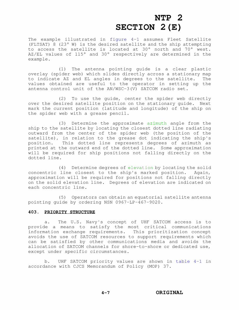
NTP 2SECTION 2(E)
The example illustrated in figure 4-1 assumes Fleet Satellite(FLTSAT) 8 (23° W) is the desired satellite and the ship attemptingto access the satellite is located at 30° north and 70° west.AZ/EL values of 115° and 30° respectively are determined in theexample.
(1) The antenna pointing guide is a clear plasticoverlay (spider web) which slides directly across a stationary mapto indicate AZ and EL angles in degrees to the satellite. Thevalues obtained are useful to the operator in setting up theantenna control unit of the AN/WSC-3(V) SATCOM radio set.
(2) To use the guide, center the spider web directlyover the desired satellite position on the stationary guide. Nextmark the current position (latitude and longitude) of the ship onthe spider web with a grease pencil.
(3) Determine the approximate azimuth angle from theship to the satellite by locating the closest dotted line radiatingoutward from the center of the spider web (the position of thesatellite), in relation to the grease dot indicating the ship'sposition. This dotted line represents degrees of azimuth asprinted at the outward end of the dotted line. Some approximationwill be required for ship positions not falling directly on thedotted line.
(4) Determine degrees of elevation by locating the solidconcentric line closest to the ship's marked position. Again,approximation will be required for positions not falling directlyon the solid elevation line. Degrees of elevation are indicated oneach concentric line.
(5) Operators can obtain an equatorial satellite antennapointing guide by ordering NSN 0967-LP-467-9020.
403. PRIORITY STRUCTURE
a. The U.S. Navy's concept of UHF SATCOM access is toprovide a means to satisfy the most critical communicationsinformation exchange requirements. This prioritization conceptavoids the use of SATCOM resources to support requirements whichcan be satisfied by other communications media and avoids theallocation of SATCOM channels for shore-to-shore or dedicated use,except under specific circumstances.
b. UHF SATCOM priority values are shown in table 4-1 inaccordance with CJCS Memorandum of Policy (MOP) 37.
4-7 ORIGINAL

NTP 2SECTION 2(E)
PRIORITY USER CATEGORY PRIORITY USER CATEGORY
Priority I STRATEGIC ORDER (Essential to National
Survival)
A. SystemControl/Orderwire
B. NCA- Presidential Support- Secretary of DefenseSupport
C. StrategicWarning/Intelligence
D. SIOP requirements
Priority V VIP SUPPORT
A. ServiceSecretaries
B. Chiefs of theServices andcommanders ofunified andspecifiedcommands
C. Other
PriorityII
WARFIGHTING REQUIREMENTS
A. Department of StateDiplomatic Negotiations
B. CJCSC. CINCD. JTF/CTFE. Component Support
(e.g., theater forces)F. Tactical Warning
(Intelligence)G. CJCS-sponsored and
other selectedexercises
H. Counternarcoticsoperations
Priority VI RDT&E
A. DOD test anddemonstration
PriorityIII
ESSENTIAL SUPPORT
A. Other intelligence(e.g., technical,economic)
B. WeatherC. LogisticsD. MIJI support (for
efforts supporting aspecific user problem,effort will havepriority of user beingaffected)
E. Diplomatic post supportF. Minimum circuits for
TT&C from spacevehicles and primarycircuits manned spaceflights
G. Other Service support
Priority VII MISCELLANEOUS
A. DOD support toLawEnforcementAgencies
B. Non-DODsupport
C. Non-U.S.support
D. Other
PriorityIV
TRAINING
User Priority ValuesTable 4-1
4-8 ORIGINAL

NTP 2SECTION 2(E)
404. POWER CONTROL
a. Control of power radiated by users is an importantfactor in the operation of FLTSATCOM. In FLTSAT, Leased Satellite(LEASAT), and GAPFILLER wideband channel operations, multiple usersshare available transponder power. Users must strictly adhere toauthorized power levels since any user can, by exceeding theassigned power level, completely disrupt services provided to otherusers. To maintain an adequate degree of power discipline whenusing the wideband channel of the FLTSATCOM satellites, all UHFSATCOM transmitters must be power calibrated:
(1) When initially accessing the satellite,
(2) Immediately following terminal maintenance,
(3) Upon getting underway after extended inportperiods,
(4) Anytime a change in terminal characteristics isdetected and suspected, or
(5) At least once per year in accordance with plannedmaintenance.
b. Power sharing is not a factor in FLTSAT, LEASAT, or UHFFollow-on (UFO) narrowband channel operations dedicated to specificuses (i.e., Common User Digital Information Exchange Subsystem,demand assigned Multiple access). These services are provided viaindividual 25-kHz channels which have independent transponders.Only one user can access a given channel at one time. The onlypotential power problem in this multiple access environment is theuse of insufficient power.
c. Power calibration services will be coordinated by theNCTAMS for fleet units in their respective communication areas.Units may request a power calibration by routine message to therespective NCTAMS. The request should indicate a primary andalternate date, and the number of AN/WSC-3(V)'s to be calibrated.In emergency situations, power calibrations may be arranged bycontacting the appropriate NCTAMS via primary ship-to-shore.
(1) Power calibration is accomplished by means of theInterim FLTSATCOM Spectrum Monitor (IFSM) maintained at each of theNCTAMS. The IFSM can also be used for frequency spectrum scanningor for intermodulation and can be operated in either a manual entryor reduced capability mode. Standard operating proceduresmaintained at the NCTAMS assist operators in performing powercalibration.
(2) Prior to acting on a power calibration request, theNCTAMS operator will verify the operational status of the IFSM and
4-9 ORIGINAL
NTP 2SECTION 2(E)
program it accordingly. Using the UHF SATCOM AN/WSC-5(V), theoperator will establish a power reference for use during the actualcalibration. With the reference established, the requesting unitis then directed to configure SATCOM equipment for a 75 baudcircuit with a power output of 21 dBW. The satellite, frequencyplan, and channel to be used during the power calibration will alsobe relayed by the NCTAMS operator.
(3) The NCTAMS operator will then program the IFSM asfollows:
(a) Mode of operation (i.e., spectrum scan,intermodulation, or power calibration),
(b) Select system (i.e., Atlantic, Pacific),
(c) Select satellite (i.e., FLTSAT, LEASAT, or UFO),
(d) Select frequency plan (i.e., W=LEASAT LANT),
(e) Select satellite channel for reference (e.g.,1,2, or 3), and
(f) Select satellite channel for power calibration(e.g., 1,2, or 3).
(4) Once all operating parameters are entered into theIFSM and verified, power calibration operations are initiated. Allinformation relative to the operation appears on the IFSM screen.The NCTAMS operator will advise the requesting unit of requiredpower adjustments until the calibration is complete.
(5) At the scheduled time, the requesting unitestablishes a secure link with the NCTAMS, using an effectiveisotropic radiated power of 8 dBW. After establishingcommunications, shipboard personnel verify the correct azimuth andelevation of shipboard antenna systems; when the antenna has beenproperly oriented, the power calibration routine proceeds asoutlined in the appropriate planned maintenance system maintenancerequirement card.
(6) Upon completion, the NCTAMS will send a routinemessage to the requesting unit confirming the power calibrationcompletion date and any problem encountered.
405. RADIO FREQUENCY INTERFERENCE (RFI)
a. Incidents of meaconing, intrusion, jamming andinterference (MIJI) to U.S. military electromagnetic equipment orsystems are reported by MIJI reports. However, the Joint Staffterminated the DOD MIJI reporting system under management control
4-10 ORIGINAL

NTP 2SECTION 2(E)
of the Joint Electronic Warfare Center (JEWC) effective 3 April1992. The entire MIJI program is currently being reevaluated bythe Services to determine what is required. Until further guidanceis promulgated, delete JEWC as addressee on all MIJI reports.Submit SATCOM MIJI report as follows:
PRECEDENCE/DATE TIME GROUPFM ORIGINATORTO COMNAVSPACECOM DAHLGREN VA//NAVSPOC/N3//HQ USSPACECOM CHEYENNE MOUNTAIN AFB CO//SPADOC/C3SOT//INFO COMNAVCOMTELCOM WASHINGTON DC//N3/N32//NAVTECHINTCEN WASHINGTON DC//DA44//
The report may also include a request for RFI geolocationsupport (Lifeline).
Additionally, send all SATCOM MIJI reports by immediateprecedence to ensure appropriate Lifeline or geolocationof RFI (previously known as GOFR) action is taken afternormal working hours and Space Defense Operations Center(SPADOC) is advised of SATCOM RFI incidents in a timelymanner.
b. The location of jamming and interference sourcesaffecting naval/joint UHF SATCOM is accomplished by a systemreferred to as Lifeline. Located at COMNAVSPACECOM Dahlgren, VA,this real-time operational system employs various RFI geolocationtechniques in determining RFI sources adversely affecting satellitecommunications.
(1) The Lifeline system makes use of time differenceof arrival (TDOA), frequency difference of arrival (FDOA), combinedTDOA/FDOA, and single satellite doppler techniques in locatingsources of RFI affecting the Atlantic (LANT) and Continental UnitedStates (CONUS) FLTSATCOM (FLTSAT's and LEASAT's) communicationspayloads.
(2) Data accompanying the request should include thefollowing.
(a) Satellite plain language name, ID number, andchannel (table 4-2 contains a listing of satellite identificationdata).
4-11 ORIGINAL

NTP 2SECTION 2(E)
SATELLITE ID NUMBER
FLTSATCOM-1 10669
FLTSATCOM-4 12046
FLTSATCOM-7 17181
FLTSATCOM-8 20253
LEASAT-1 15384
LEASAT-2 15236
LEASAT-3 15643
LEASAT-5 20410
GAPSAT-1 8882
GAPSAT-3 9478
Satellite Identification DataTable 4-2
(b) Frequency affected.
(c) Bandwidth affected.
(d) Signal strength.
(e) Modulation type (i.e., modulated, unmodulated).
(f) Signal characteristics (i.e., intermittent,constant, steady carrier).
(g) Operational impact, including circuit affected and restoral priority.
c. The NCTAMS or Naval Communications Station (NAVCOMMSTA)experiencing MIJI is responsible for data collection, compilationand forwarding of MIJI reports. In the case of satellite channelsassigned to fleet units, the appropriate NCTAMS shallcompile/coordinate the data and submit the MIJI report. Thisrecognizes that in many cases the NCTAMS is not the end user of thechannel, but it also reduces the burden on fleet units who are notin the best position to identify interfering signal parameters.
d. Coordination between the reporting unit and the servingNCTAMS will aid in determining the need to refer the incident forgeolocation efforts. COMNAVCOMTELCOM, acting on the operationalstatus reporting of the NCTAMS, will coordinate with Commander,Naval Space Command (COMNAVSPACECOM) if geolocation efforts arewarranted. RFI support service requests are acted upon by the
4-12 ORIGINAL
NTP 2SECTION 2(E)
Naval Space Operations Center (NAVSPOC), a separate code within theCOMNAVSPACECOM organization. A NAVSPOC watch officer maintains theoperational status of all space systems providing service orproducts to the fleet and performs other monitoring, interface,configuration, and communications functions. However, if theaffected satellite/channel is outside the COMNAVSPACECOM field ofview, coordination with Headquarters, US Space Command (HQUSSPACECOM)/SPADOC will be necessary in order to bring other assetsto bear on the geolocation effort.
e. The area NCTAMS should be consulted when a NAVCOMMSTA,Naval Computer and Telecommunications Station (NAVCOMTELSTA) orother COMNAVCOMTELCOM activity is experiencing MIJI. Evidence haspointed toward friendly forces as the source of MIJI in some cases.It is incumbent upon the NCTAMS to establish specific guidance inthe area Fleet Telecommunication Procedure concerning MIJIreporting. After a maximum of one hour, the affected circuitshould be restored via alternate circuitry. This is a judgmentcall and depends on circuit priority, available assets, etc. Aftertwo hours of interference, a MIJI report must be sent even if thecircuit has been restored via other means.
406. CRISIS AND CONTINGENCY COMMUNICATIONS
a. Experience has demonstrated that even a limited UHFSATCOM capability can significantly improve the flow of command andcontrol information between a FLTCINC and the forces assigned.Existing and planned U.S. Navy UHF SATCOM resources, the variousautomated information exchange subsystems, expanding secure voicecapabilities, and automated fleet and message center operationswill substantially improve the ability of the NCTS to respond tothe traffic surges which normally accompany crisis situations.Nevertheless, there will be occasions when some manipulation of UHFSATCOM capabilities and services will be required to respondeffectively to the demands for service generated in crisis andcontingency operations.
b. Naval Crisis and Contingency Requirements. The FLTCINCis the U.S. Navy focal point for the direction and support of navalforces operating at sea. OPNAVINST 5450.184 assigns the FLTCINC'sauthoritative direction and control of designated tacticalcommunications functions performed by activities ofCOMNAVCOMTELCOM, with due consideration to system and Service-widerequirements. This authoritative direction and control includesdirection to NCTAMS for operational adjustments or temporarynetwork changes required to support contingency or emergencysituations. Within this context, NCTAMS LANT is responsive toCommander in Chief, U.S. Atlantic Fleet, NCTAMS Mediterranean (MED)to Commander in Chief, U.S. Naval Forces Europe, and NCTAMS EasternPacific/Western Pacific (EASTPAC/WESTPAC) to Commander in Chief,
4-13 ORIGINAL

NTP 2SECTION 2(E)
U.S. Pacific Fleet.
(1) There are a number of actions which may be directedby the FLTCINC's to improve command and control capabilities in acrisis situation. These actions are consistent with theauthoritative direction and control assigned to each FLTCINC, andshould not impact on other FLTCINC's if all satellites and NCTAMSterminals are functioning normally.
(2) The coverage areas of most on-orbit satellites canprovide SATCOM service to at least two FLTCINC's. Any station hasthe capability to divert resources from support of one FLTCINC tothe support of another. In two specific cases (NCTAMS WESTPAC andMED), the basic concept of operations includes the allocation ofresources in one theater to provide primary or alternate support toforces operating in another. Thus, in the strictest sense, anymanipulation of UHF SATCOM resources has a system-wide implication.
c. Non-U.S. Navy Requirements. The allocation of U.S. NavyUHF SATCOM resources to support non-U.S. Navy users will normallybe in accordance with MOA's or other suitable agreements negotiatedin advance between the department or agency concerned and CNO.
(1) It can be anticipated that under certain crisisconditions, the U.S. Navy will be tasked to provide unplannedservices, in accordance with CJCS MOP 37, to support requirementsof the NCA, Chairman of the Joint Chiefs of Staff, unified andspecified commanders, or other authorities. The support of suchunforeseen requirements may require the temporary preemption andreallocation of UHF satellite resources. To minimize the impact onU.S. Navy subscribers, the precise manner in which non-U.S. Navyrequirements are to be satisfied will be determined by CNO, inclose coordination with COMNAVCOMTELCOM and appropriate FLTCINC's,and the Joint Communications Satellite Center as required.
(2) The U.S. Navy and U.S. Air Force have developedprocedures for sharing UHF SATCOM. MOA's address use of existingsystems for which either the U.S. Navy (FLTSATCOM) or the U.S. AirForce (AFSATCOM) is the system manager. COMNAVCOM-TELCOM and theU.S. Air Force Space Command have been assigned responsibility forcoordinating services.
4-14 ORIGINAL

NTP 2SECTION 2(E)
CHAPTER 5
ADMINISTRATIVE PROCEDURES
501. GENERAL
The ultra high frequency (UHF) satellitecommunications (SATCOM) system provides reliable, longhaul communications networks to a variety of platformsranging from single channel equipment to complex multiplesubsystems. Administrative procedures are necessary forcontrol of satellite access, to ensure that the systemsare meeting authorized requirements during peacetime andcontingency operations.
502. INTEGRATED MILSATCOM (MILITARY SATELLITECOMMUNICATIONS)MANAGEMENT INFORMATION SYSTEM (IMMIS)
This system (formerly User Requirements Database(URDB)) provides the means to validate communicationsrequirements leading to utilization of Fleet SatelliteCommunications (FLTSATCOM). Validation of a requirementand the subsequent granting of an Integrated SATCOM(Satellite Communications) Database (ISDB) number doesnot automatically ensure actual access to the FLTSATCOM.Implementation of UHF access is authorized by the FleetCommander in Chief (FLTCINC) for his area followingassignment of resources by the Chief of Naval Operations(CNO). ISDB submissions are normally required prior toaccess and serve as a basis for Chairman of the JointChiefs of Staff (CJCS) validation of approvedrequirements. ISDB submissions for the naval Servicescan originate from several sources: CNO, the Commandantof the Marine Corps (CMC), a FLTCINC (through the CNO),a Fleet Marine Forces Commander (through CMC), or aunified/specified commander in chief (CINC) (for navalforces supporting joint requirements). The JointStaff/Joint Communications Satellite Center (JCSC),acting for the Chairman of the Joint Chiefs of Staffmanages the ISDB process and develops policy and guidancethat is published in CJCS Memorandum of Policy (MOP) 37.The Director, Defense Information Systems Agency (DISA)administers the ISDB for the Chairman of the Joint Chiefsof Staff. Normally, the Joint MILSATCOM Panel(consisting of Service, JCSC, and DISA representatives)meets at least once a month to review ISDB submissionsand to make recommendations regarding final approval ordisapproval. The JCSC then initiates a joint action tovalidate the requirements. Validated requirements will
5-1 ORIGINAL

NTP 2SECTION 2(E)
be assigned a number and entered into the ISDB. Thenumbers will be provided to the originator of the requestwith the assigned priority. Disapproved requests withcomments will be returned to the user.
503. ISDB SUBMISSIONS
The Chairman of the Joint Chiefs of Staff, CINC's,Services, and Defense agencies are the advocates of allMILSATCOM requirements. The CINC's are the advocates fortheir respective area of responsibility/area ofoperations (AOR/AOO). Each CINC will consolidate,validate, and prioritize all requests for use ofMILSATCOM systems within the AOR/AOO. The U.S. Navy andU.S. Marine Corps will validate and submit, throughappropriate channels, service requirements for systemdevelopment and testing, training, organizing, andequipping forces. CINC's and Services will carefullyreview each requirement and the associated performancecharacteristics and attributes identified to ensure eachrequirement:
- Is valid.
- Has a clear operational concept.
- Identifies all operation plans, operationorders, communications plans, and implementationdirectives supported.
- Identifies missions supported.
- Provides a mission impact if not satisfied.
Naval requirements that are ongoing/continuing donot require an ISDB submission each time forces deploy.Access under previously approved requirements is achievedas described in chapter 4 of this NavalTelecommunications Procedure.
a. Urgent ISDB Requirements. Urgent ISDBrequirements are submitted by the FLTCINC's or a unifiedand specified commander directly to the Joint Staff/JCSCwith information copies to the respective chain ofcommand and the Joint MILSATCOM Panel Administrator(JMPA). The submission must contain adequatejustification for the urgency. The Joint Staff willinitiate validation action as appropriate.
b. ISDB Guidelines. Guidelines for completing
5-2 ORIGINAL

NTP 2SECTION 2(E)
ISDB submissions can be found in DISA IntegratedMILSATCOM Management System, User Requirements Database(URDB) User Requirements Form, dated August 9, 1991.
504. REPORTING REQUIREMENTS
a. The reporting procedures established fordirection and control of tactical communications forshore, fleet, and research and development activities arebased upon Joint Reporting System requirements in NavalWarfare Publication (NWP) 10-1-13 (SUPP 1). Thispublication contains modifications which are designed tohighlight that information required to ensure effectivemanagement, control, and use of SATCOM resources.
b. Communications Spot Report (COMSPOT).COMSPOT's will be submitted by shore, fleet, and researchand development activities, including non-terminatedunits, when local efforts to resolve communicationsoutage are not successful or exceed 30 minutes. Shipswill submit a COMSPOT to the terminating Naval Computerand Telecommunications Area Master Station (NCTAMS),information to the numbered fleet commander. Timelysubmission of COMSPOT reports is necessary to minimizefurther deterioration of communication circuits. Anychanges in status, including restoration ofcommunications, will also be reported via a COMSPOT. Thefollowing is an example of a COMSPOT report.
PRECEDENCE/DATE TIME GROUPFM (ORIGINATOR)TO (TERMINATING STATION)// //INFO (CHAIN OF COMMAND)// //BTCLASSIFICATION //N02308// (CLASSIFY ONLY IF CONTENTSWARRANT)MSGID/GENADMIN/NAVCOMM DET NORFOLK/4A/FEB//SUBJ/COMSPOT//REF/A/RMG/ORIGINATOR/DATE TIME GROUP//AMPN/(FREE TEXT TO AMPLIFY REFERENCE)//COMEV/(EVENT)/(START TIME)/(END TIME)/(SYSTEM)//RMKS/1. SHIPS POSITION.2. DESCRIPTION OF PROBLEM; STATE CORRECTIVE ACTIONTAKEN BY UNIT.3. RECOMMENDED SOLUTION//DOWNGRADING INSTRUCTIONS IF REQUIRED//BT
505. OPERATIONAL TRAINING
5-3 ORIGINAL

NTP 2SECTION 2(E)
a. Courses. Formal training courses for U.S. Navy UHFSATCOM systems and subsystems are primarily conducted at FleetTraining Center (FLETRACEN), Norfolk, VA and Advanced ElectronicsSchool, Service School Command (SERVSCOLCOM) Annex, Naval Station,San Diego, CA. The training courses available are listed belowsequentially by course number. The list also includes courses forsystems which are not specifically part of U.S. Navy UHF SATCOM butuse UHF SATCOM access.
(1) AN/WSC-3(V) UHF SATCOM Operator and Maintenance,course number A-101-0138. The course trains personnel in theoperation and maintenance of the generic AN/WSC-3(V) communicationsset and the associated AN/SRA-33 and OA-9123/SRC antenna couplersand the OE-82B/C antenna. The course is conducted at FLETRACEN,Norfolk, VA and SERVSCOLCOM Annex, Naval Station, San Diego, CA.
(2) AN/USQ-64(V)2 Common User Digital InformationExchange Subsystem (CUDIXS), course number A-101-0082. The coursetrains personnel in the operation and maintenance of the AN/USQ-64(V)2, CUDIXS shore configuration which includes the AN/WSC-5(V),the interim FLTSATCOM spectrum monitor, and the UHF demand assignedMultiple access (DAMA) multiplexer set. The course is conducted atSERVSCOLCOM Annex, Naval Station, San Diego, CA.
(3) Officer in Tactical Command and Tactical DataInformation Exchange Subsystem-A (OTCIXS/TADIXS-A) Maintenance,course number A-101-0221. The course trains personnel in theskills and knowledge to operate and maintain the OTCIXS and TADIXScommunications system which includes the ON-143(V)6 and AN/UGC-136BX. The course is conducted at FLETRACEN, Norfolk, VA andSERVSCOLCOM Annex, San Diego, CA.
(4) Submarine Radioman Receive OTCIXS and TADIXS-AOperation and Maintenance Training, course number A-101-0223. Thecourse trains personnel in operations and maintenance of the OTCIXSand TADIXS-A equipment which includes the ON-143(V)6 and AN/UGC-136CX. The course is conducted at Submarine School, Groton, CT.
(5) Tactical Intelligence (TACINTEL) Operator, coursenumber A-231-0052. The course trains personnel to operate theAN/USQ-64 TACINTEL subsystem including the following associatedshipboard communications equipment and system: AN/URA-17, R-1051B,KW-46, KG-84A, and system OUTBOARD. The course is conducted atNaval Technical Training Center (NAVTECHTRACEN), Pensacola, FL.
(6) VHF/UHF/SHF Theory, course number A-232-0070. Thecourse trains personnel in the basic knowledge to effectivelyoperate in the very high frequency (VHF)/UHF/super high frequency(SHF) spectrums; included are overviews of modulation/demodulation,radiowave propagation, multiplexing schemes, and satellite
5-4 ORIGINAL

NTP 2SECTION 2(E)
communications. The course is conducted at NAVTECHTRACEN,Pensacola, FL.
(7) Submarine Satellite Information Exchange Subsystem(SSIXS II) Shore Communications Operator, course number A-260-0031.The course trains personnel in the operation of the SSIXS IIcommunications center equipment as supervised by a qualified watchsupervisor. The course is conducted at FLETRACEN, Norfolk, VA.
(8) AN/SYQ-7(V)2 Naval Modular Automated CommunicationsSystem (NAVMACS) (V)2 Operator, course number A-260-0033. Thecourse trains personnel in the operating procedures for the NAVMACS(V)2. The course is conducted at FLETRACEN, Norfolk, VA andSERVSCOLCOM Annex, San Diego, CA.
5-5 ORIGINAL

NTP 2SECTION 2(E)
(9) AN/SYQ-7(V)3 Naval Modular Automated Communi-cations System (NAVMACS) (V)3 Operation, course number A-260-0037.The course trains personnel to operate, with limited supervision,the NAVMACS (V)3 aboard naval ships. The course is conducted atFLETRACEN, Norfolk, VA and SERVSCOLCOM Annex, San Diego, CA.
(10) AN/SYQ-7(V)5 NAVMACS (V)5 Database Management,course number A-260-0047. The course trains personnel to constructand maintain a database for use with the NAVMACS (V)5. The course is conducted at FLETRACEN, Norfolk, VAand SERVSCOLCOM Annex, San Diego, CA.
(11) AN/SYQ-7(V)5 Naval Modular Automated Communi-cations System, course number A-260-0065. The course trainspersonnel to effectively operate and manipulate AN/SYQ-7(V)5NAVMACS with limited supervision. The course is conducted atFLETRACEN, Norfolk, VA and SERVSCOLCOM Annex, San Diego, CA.
(12) Officer in Tactical Command/Tactical DataInformation Exchange Subsystems-A (OTCIXS/TADIXS-A) Operator Coursenumber A-260-0050. The course trains Combat Information CenterWatch Officers and enlisted personnel to operate the AN/USQ-64(V)7OTCIXS and the AN/USQ-64(V)8 TADIXS-A communications systems. Thecourse is conducted at FLETRACEN, Norfolk, VA and SERVSCOLCOMAnnex, San Diego, CA.
(13) Fleet Imagery Support Terminal (FIST) Operator,course number J-243-1950. The course trains personnel to operatethe FIST system under simulated operational conditions. The courseis conducted at the U.S. Navy and Marine Corps IntelligenceTraining Center, Dam Neck, Virginia Beach, VA.
(14) TADIXS-B and Tactical Receive Equipment (TRE)System Operator and Maintenance, course number A-101-0230. Thecourse trains personnel in the operation and maintenance of theTADIXS-B and TRE system. The course is conducted at NavalSubmarine School, Groton, CT. Maintenance course A-101-0270 isalso available at Advanced Electronics School, SERVSCOLCOM Annex,San Diego, CA and FLETRACEN, Norfolk, VA.
b. Personnel Qualification Standards (PQS). Theapplicable PQS for UHF SATCOM for each class of ship should beincluded in the unique PQS for radio communications of the variousclasses. Table 5-1 lists the PQS title with NAVEDTRA number andstock number of the LHA 1 and LCC 19 as examples of unique radiocommunications PQS. The applicable PQS for the AN/WSC-3(V) and theAN/WSC-5(V) have been incorporated in several UHF SATCOM system PQSbooks.
5-6 ORIGINAL

NTP 2SECTION 2(E)
PQS NAVEDTRA NO. STOCK NO.
LHA 1 Class RadioCommunications (UNIQUE)
43315-5B 0501-LP-223-1520
LCC 19 Class RadioCommunications (UNIQUE)
43317-5A 0501-LP-223-1703
Radio Communications(COMMON)
43355-5A 0501-LP-233-6535
Communications SystemTechnical ControlAshore
43465 0501-LP-224-3250
PQS for UHF SATCOMTable 5-1
5-7 ORIGINAL

ANNEX A TO NTP 2SECTION 2(E)
ANNEX A
FLEET SATELLITE BROADCAST
1. INTRODUCTION
The purpose of this annex is to provide informationrelated to the operation of the fleet satellitebroadcast.
2. SUPER HIGH FREQUENCY (SHF) FLEET SATELLITEBROADCAST SUBSYSTEM
The SHF Fleet Satellite Broadcast Subsystemprovides the capability to transmit fleet broadcastmessage traffic in a jamming environment through the useof a jam-resistant, direct sequence spread spectrum SHFuplink signal transmitted via the AN/FSC-79 satellitecommunications (SATCOM) terminal. The fleet satellitebroadcast comprises 15 channels of encrypted messagetraffic at an input data rate of 75 bits per second (bps)per channel. These channels are time divisionmultiplexed and transmitted as the SHF uplink signal ina one-way radio frequency (RF) transmission at 1200 bps.The space based segment of the subsystem consists of theFleet Satellite Communications (FLTSATCOM) constellationwhich is capable of receiving the uplinked signal andaccomplishing onboard translation to ultra high frequency(UHF) before broadcast to subscribers. The FleetSatellite Broadcast Subsystem is illustrated in figure A-1.
3. MESSAGE TRAFFIC INPUT
a. Fleet satellite broadcast message traffic isprocessed, queued, and channelized prior to transmissionby two processor-controlled switching systems. Forgeneral service (GENSER) message traffic, the NavalComputer Processing and Routing System (NAVCOMPARS)receives message traffic from automated sources, over-the-counter facilities, dedicated subscriber ports,tactical circuits, and through interconnects with othermessage processing and control systems. NAVCOMPARSsoftware automates broadcast functions and provides forthe automatic recognition of individual messageaddressees and routing of those messages to theappropriate broadcast channel for transmission.STREAMLINER functions similarly in processing specialintelligence (SI) message traffic received from automatedor dedicated subscriber sources and the Ocean
A-1 ORIGINAL

ANNEX A TO NTP 2SECTION 2(E)
Surveillance Information System (OSIS). Fleet satellitebroadcast message traffic is segregated into separatechannels operating at 75 bps. Exact channelization mayvary by ocean area. The appropriate Naval Computer andTelecommunications Area Master Station (NCTAMS)Communications Information Bulletins should be reviewedfor the area in which operations are conducted.Additionally, the fleet satellite broadcast transmissionmakes use of a sixteenth channel for framesynchronization.
A-2 ORIGINAL

ANNEX A TO NTP 2
SECTION 2(E)
Figure A-1
Fleet Satellite Broadcast Subsystem
A-3
ORIGINAL

ANNEX A TO NTP 2SECTION 2(E)
b. Once channelized, message traffic is encryptedand multiplexed. Through time division multiplexing, thebroadcast package becomes a 1200 bps data stream which isnormally passed to the SHF or to the UHF satellitetransmission system.
4. RF TRANSMISSION
a. Fleet Satellites (FLTSAT's) and LeasedSatellites (LEASAT's) make use of two RF channels forfleet satellite broadcast message support. The firstchannel is configured for SHF operation and is used asthe primary mode for fleet broadcast transmission. Onlythe uplink portion of the broadcast signal is SHF. Thedownlink portion of the broadcast is UHF aftertranslation within the satellite. The second RF channelis intended as a backup for the primary SHF broadcastsignal. This channel is configured for uplink anddownlink operation in the UHF band. The second RFchannel may be used as required by the Fleet Commander inChief (FLTCINC) as a means to provide a tailoredbroadcast in support of mission requirements.
b. When transmitting via channel 1 of the FLTSATand LEASAT, the time division multiplexer (TDM) outputwill be patched to the AN/FSC-79 SATCOM terminal.Transmitting via channel 2 requires the multiplexeroutput be patched to the AN/WSC-5(V) UHF transceiver.
c. The availability of two satellite channels andthe option of using several different RF modulationtechniques in uplinking fleet satellite broadcast messagetraffic make possible seven different transmission modes.
d. In modes 1-6, the SHF transmissions are madeby the AN/FSC-79 SATCOM terminal. Mode 7 permits UHFuplink and downlink operation using the AN/WSC-5(V)transceiver.
e. Fleet satellite broadcast transmissions arecontrolled by subsystem components.
(1) Message traffic control, in terms ofchannel assignment, handling, precedence levels, andaccountability, is accomplished within the software ofNAVCOMPARS and STREAMLINER processors.
(2) The operational modes listed in table A-1provide control of fleet satellite broadcast RFtransmission. Mode 1 is the standard operating mode.
A-4 ORIGINAL

ANNEX A TO NTP 2SECTION 2(E)
Changing to modes 2-6 requires a command to thesatellite.
MODE SHF UHF
Channel 1 Channel 2
1. Spread Spectrum(Primary Mode)
Uplink Downlink N/A
2. Spread Spectrum Uplink N/A Downlink
3. Narrowband (OM-51Amodem)
Uplink Downlink N/A
4. Narrowband (OM-51Amodem)
Uplink N/A Downlink
5. Narrowband (OM-43Amodem)
Uplink Downlink N/A
6. Narrowband (OM-51Amodem)
Uplink N/A Downlink
7. UHF N/A N/A Uplink andDownlink*
* Via Channel 3 on LEASATFleet Satellite Broadcast Transmission Modes
Table A-1
5. SUBSCRIBER RECEPTION
Subscribers receive the fleet satellite broadcastUHF downlink signal with either an AN/SSR-1 or AN/SSR-1Areceiver. The receiver demodulates and demultiplexes thesignal before decryption and ultimate interface with theNaval Modular Automated Communications System (NAVMACS).Up to four channels of traffic can be processed formessage screening and printing. SI channels aresimilarly screened by the tactical intelligence(TACINTEL) processor. Subscriber terminals that do nothave NAVMACS (e.g., patrol hydrofoil missiles (PHM) andmine sweeper ocean (MSO)) or TACINTEL processors guardselected fleet broadcast channels and output data toteletypewriters. Table A-2 contains the broadcastequipment configuration.
Message Processing Ashore • NAVCOMPARS (GENSER and emergency actionmessage (EAM) traffic)• STREAMLINER (SI message traffic)
Message Processing Afloat • NCTAMS (GENSER and EAM traffic)• TACINTEL (SI traffic)
A-5 ORIGINAL

ANNEX A TO NTP 2SECTION 2(E)
Message Encryption/Decryption • KWT-46 (shore based transmitter)• KWR-46 (subscriber receiver unit)
Multiplexing • TD-1150/USC TM• TD-1389(V)4/TSC LRM
Shore Based RF Terminal • OM-51A/FR modem• OM-43A/USC digital data modem• AN/FSC-79 SATCOM terminal (SHF)• AN/WSC-5(V) transceiver (UHF)
Subscriber RF Terminal • AN/SRR-1 or AN/SRR-1A receiver
NOTE: The OM-43A/USC modem can be used with the AN/FSC-79 terminal, but isnormally used with the AN/WSC-5(V).
Fleet Satellite Broadcast Subsystem Equipment ConfigurationTable A-2 (continued)
6. FLEET SATELLITE BROADCAST INSTALLATIONS
Table A-3 provides the five locations capable ofbroadcast transmission and control. All five locationshave the capability to transmit via the AN/FSC-79 SATCOMterminal or the AN/WSC-5(V) transceiver. Table A-4 liststhe broadcast control station (BCS) and alternatebroadcast control station (ABCS) assignments.
INSTALLATION/BROADCAST DESIGNATOR
LOCATION EQUIPMENT
NCTAMS LANT(LMUL)
Norfolk, VANorthwest, Chesapeake,VA
AN/WSC-5(V)AN/FSC-79
NCTAMS MED(MMUL)
Bagnoli, ItalyLago di Patria, Italy
AN/WSC-5(V)AN/FSC-79
NCTAMS WESTPAC (GMUL) Finegayan, Guam AN/WSC-5(V)AN/FSC-79
NCTAMS EASTPAC (HMUL) Wahiawa, HI AN/WSC-5(V)AN/FSC-79
NAVCOMMSTA Stockton Stockton, CA AN/WSC-5(V)AN/FSC-79
Fleet Satellite Broadcast RF Terminal InstallationsTable A-3
BROADCAST BCS ABCS
LANT NCTAMS LANT NCTAMS MED
MED NCTAMS MED NCTAMS LANT
WESTPAC NCTAMS WESTPAC NCTAMS EASTPAC
A-6 ORIGINAL

ANNEX A TO NTP 2SECTION 2(E)
EASTPAC NCTAMS EASTPAC NCTAMS WESTPAC
BCS/ABCS AssignmentsTable A-4
7. CURRENT OPERATIONS
a. Fleet broadcast support is provided to eachmajor ocean area by the NCTAMS. Each is capable oforiginating one or more broadcasts to support areaoperations. Broadcast transmission is effected primarilythrough the AN/FSC-79 SATCOM terminal on channel one ofthe FLTSAT or LEASAT. Fleet satellite broadcast messagesare routed by the NAVCOMPARS to the appropriate broadcastchannel for transmission. Broadcast alignment can bechanged in accordance with the operational requirementsof the FLTCINC. In addition to the SHF satellitebroadcast, each NCTAMS is capable of providing broadcastpackages via UHF satellite or high frequency.
b. Procedures for assuming guard for the fleetsatellite broadcast are accomplished through acommunications shift message. These procedures are foundin Naval Telecommunications Procedure 4.
A-7 ORIGINAL

ANNEX B TO NTP 2SECTION 2(E)
ANNEX B
OFFICER IN TACTICAL COMMAND INFORMATION EXCHANGE
SUBSYSTEM
(OTCIXS)/TACTICAL DATA INFORMATION EXCHANGE SUBSYSTEM
(TADIXS)
1. INTRODUCTION
a. OTCIXS. OTCIXS is designed to provide a two-way satellite link (half-duplex mode) to supportinterbattle group and intrabattle group over-the-horizontargeting (OTH-T) and command and control communicationsrequirements. OTCIXS is capable of handling bothteletypewriter (TTY) message traffic and tactical dataprocessor (TDP) formatted data on an automaticallycontrolled time-shared basis over the same OTCIXSsatellite channel. Figure B-1 illustrates the OTCIXSnetwork.
B-1 ORIGINAL

ANNEX B TO NTP 2SECTION 2(E)
b. Using both dedicated connectivity and
Figure B-1OTCIXS Network
satellite links TADIXS A provides integrated worldwidebroadcast connectivity among the OTH-T community. Netoperations consist of event-by-event and scheduledbroadcasts from shore support TDP systems to afloatsubscribers. Selected flag configured TADIXS A afloatsubscribers have TADIXS A transmit capability. Theremainder of TADIXS A afloat subscribers have a receiveonly capability and must respond to TADIXS A messages andqueries via OTCIXS. Figure B-2 illustrates the TADIXS Anetwork. (TADIXS B is discussed in annex C).
2. ARCHITECTURE
a. An OTCIXS (AN/USQ-64(V)7) installationconsists of an ON-143(V)6/USQ interconnecting group (IG),a cryptographic device (KG-84A for surface and KG-35/36for subsurface), and a TTY (AN/UGC-136BX for surface andAN/UGC-136CX for subsurface). Figure B-3 illustrates a
B-2 ORIGINAL
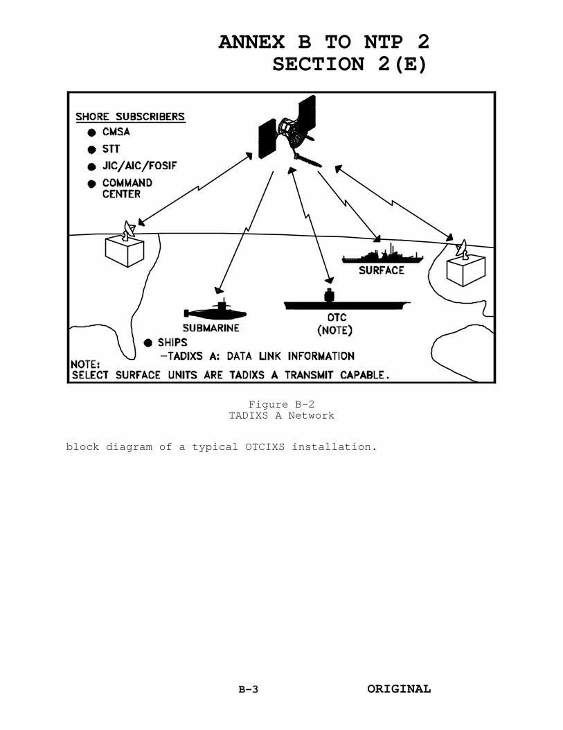
ANNEX B TO NTP 2SECTION 2(E)
block diagram of a typical OTCIXS installation.
Figure B-2TADIXS A Network
B-3 ORIGINAL

ANNEX B TO NTP 2SECTION 2(E)
(1) The ON-143(V)6/USQ IG provides automatic
Figure B-3OTCIXS Block Diagram
cryptographic synchronization, storing and forwarding ofincoming and outgoing TTY and TDP data, and control ofthe satellite link access via the AN/WSC-3(V) or AN/WSC-5(V) radio set. All subscribers are assigned asubscriber identification (SID) number which is manuallyprogrammed into the ON-143(V)6/USQ.
(2) One ON-143(V)6/USQ in the OTCIXS net mustfunction as the Net Control Station (NECOS). NECOS's areassigned by appropriate theater managers in accordancewith fleet doctrine. The NECOS automatically sets thenet mode (teletype or data), net precedence (flash orimmediate), system time, and grants net access to otherOTCIXS subscribers.
(3) In the idle-net state, the NECOS ON-143(V)6/USQ will transmit a net control blockapproximately every eleven seconds. Within the netcycle, there is a one-half second precedence request timeslot and one general access time slot which is dividedinto 20 one-half second time slots. An ON-143(V)6/USQ IG
B-4 ORIGINAL

ANNEX B TO NTP 2SECTION 2(E)
which is holding traffic for the net will automatic-allymake a random selection of one of the time slots. TheNECOS will grant net access to the subscriber with highprecedence data or to the subscriber that selects theearliest time slot.
(4) When granted net access, the subscriberON-143(V)6/USQ IG will automatically transmit all storedmessages. To ensure delivery, a subscriber may elect totransmit messages up to five times. The NECOS willrecognize this request and after the first transmissionwill allow the subscriber to retransmit all messagesbased on the number of times selected by the subscriber.
(5) After all transmissions have beencompleted, NECOS will then grant access to anothersubscriber. If there are no other access requests, thenet will return to an idle-net state, at which time theNECOS will acknowledge all successful transmissionsobserved during the previous net cycle.
(6) Most OTCIXS transmissions are generatedfrom TDP's; however, the TTY can be used to send andreceive OTCIXS record traffic and operational notes. TheTTY is also used to monitor net activity and as an aid introubleshooting equipment and net problems.
(7) Internet (e.g., surface to subsurface)and inter-ocean exchange of data is accomplished throughinterim OTCIXS gateways. The gateways are located atNaval Computer and Telecommunications Area Master Station(NCTAMS) Mediterranean (MED) Naples, Italy; NCTAMSEastern Pacific (EASTPAC) Wahiawa, HI; NavalCommunications Detachment (NAVCOMM DET) Norfolk, VA;Commander, Submarine Force, U.S. Atlantic Fleet(COMSUBLANT), Commander; Submarine Force, U.S. PacificFleet (COMSUBPAC); and Commander, Submarine Group SEVEN(COMSUBGRU 7). A gateway consists of two interconnectedON-143(V)6/USQ IG's, each subscribing to a differentOTCIXS net. Normally, the OTCIXS gateway ON-143(V)6/USQIG acts as the NECOS.
b. TADIXS A installations consist of an ON-143(V)6/USQ IG and a KG-84A cryptographic device. TheTADIXS A ON-143(V)6/USQ IG interfaces with a TDP and withthe TD-1271B/U demand assigned Multiple access (DAMA)equipment, and subsequently, the AN/WSC-3(V) radio set(or AN/WSC-5(V) transceiver set at shore radio frequency
B-5 ORIGINAL

ANNEX B TO NTP 2SECTION 2(E)
(RF) sites). Additionally, the TADIXS A ON-143(V)6/USQIG is connected to the OTCIXS ON-143(V)6/USQ IG. FigureB-4 illustrates a block diagram of a typical TADIXS Ainstallation.
(1) TADIXS A has not been implemented onsubsurface units and is primarily a one-way shore-to-shipbroadcast; however, shore subscribers exchangeinformation to ensure TDP databases are updated asrequired.
(2) A single TADIXS A network can accommodate
Figure B-4TADIXS A Block Diagram
up to 16 transmit-capable subscribers. One subscriber isdesignated the NECOS and automatically controls all netoperations.
(3) TADIXS A functions as a polled network.Subscribers can only transmit in response to NECOS netentry authorization. The NECOS maintains a polling listof transmit-capable subscribers. Each station is
B-6 ORIGINAL

ANNEX B TO NTP 2SECTION 2(E)
consecutively polled, and must respond with eithertraffic or a no-traffic reply. If a reply is notreceived after three consecutive polling cycles, thestation is deleted from the transmit list and will not bepolled again until it is recognized during a net entrycycle and added to the transmit list.
(4) TADIXS A transmit-capable subscribersmust also be able to transmit over OTCIXS.Interconnectivity between the TADIXS A/OTCIXS ON-143(V)6/USQ IG's supports this requirement. The TADIXSA transmit guard list must be manually programmed in theON-143(V)6. All messages transmitted from the TDP arescreened against the TADIXS A transmit guard list. Ifall addressed SID's are contained in the transmit guardlist, the message will be sent to the OTCIXS ON-143(V)6/USQ IG. If an exact match is not found, themessage will be transmitted over TADIXS A only. Anincorrect TADIXS A transmit guard list could result innon-delivery of messages to an OTCIXS-only configuredunit.
(5) Afloat TADIXS A subscribers may berequired to guard more than their individual SID's (e.g.,Group Call, etc.) This is accomplished by addingadditional SID's to the TADIXS A receive guard list inthe ON-143(V)6/USQ IG.
(6) Interocean exchange of data isaccomplished through interim TADIXS A gateways (identicalin design and function to the OTCIXS gateways) located atNCTAMS MED and NCTAMS EASTPAC, NAVCOMM DET Norfolk, NavalCommunications Station (NAVCOMMSTA) Stockton, CA, andCOMSUBGRU 7. The COMSUBGRU 7 gateway shifts to NCTAMSWESTPAC during Phase IV. Normally the TADIXS A gatewayON-143(V)6/USQ acts as the NECOS.
3. RELATED DOCUMENTS
The following System Operator's Manuals describethe operating procedures for OTCIXS and TADIXS A:
a. SOM(P)-6441 System Operator's Manual Volume IIfor the AN/USQ-64(V)7 Communication System (Surface)
b. SOM(P)-6442 System Operator's Manual Volume IIfor the AN/USQ-64(V)7 Communication System (Subsurface)
B-7 ORIGINAL

ANNEX B TO NTP 2SECTION 2(E)
c. SOM(P)-6443 System Operator's Manual for theAN/USQ-64(V)7 Communication System (Gateway) Release 3.2
d. SOM(P)-6444 System Operator's Manual Volume IIfor the AN/USQ-64(V)8 Communication System (Surface)
e. SOM(P)-6445 System Operator's Manual Volume IIfor the AN/USQ-64(V)8 Communication System (Subsurface)
f. SOM(P)-6446 System Operator's Manual Volume IIfor the AN/USQ-64(V)8 Communication System (Gateway)
g. SOM(P)-6447 System Operator's Manual Volume IIfor the AN/USQ-64(V)8 Communication System (Shore)
h. SOM(P)-6822 Operator's Manual (OMS) for theAN/USQ-64(V)7 and (V)8 Communication System
B-8 ORIGINAL

ANNEX B TO NTP 2SECTION 2(E)
4. USERS
OTCIXS and TADIXS A are the satellitecommunications networks which provide for the exchange oftactical warfighting command and control informationbetween TDP's and other authorized users.
5. RESPONSIBILITIES
The Fleet Commanders in Chief (FLTCINC's) haveoverall responsibility for the operation and managementof OTCIXS and TADIXS A in their areas of responsibility.Each FLTCINC's command center is the net manager for (KG-84A) OTCIXS and the supporting submarine shore targetingterminal is the net manager for (KG-35) OTCIXS. TheCommander in Chief, U.S. Atlantic Fleet Command Centerserves as the worldwide SID coordinator with each FLTCINCcommand center serving as area SID coordinator. AllOTCIXS/TADIXS A subscribers must be familiar withstanding operating procedures for the assigned area ofoperations and actions to be taken to ensure theintegrity of OTCIXS/TADIXS A nets.
B-9 ORIGINAL

ANNEX C TO NTP 2SECTION 2(E)
ANNEX C
COMMON USER DIGITAL INFORMATION EXCHANGE SUBSYSTEM
(CUDIXS) AND
NAVAL MODULAR AUTOMATED COMMUNICATIONS SUBSYSTEM
(NAVMACS)
1. INTRODUCTION
This annex provides a description of the CUDIXS andNAVMACS, discusses its operational application, andpresents information on subsystem operations.
2. CUDIXS and NAVMACS
a. CUDIXS and NAVMACS is an automated generalservice (GENSER) communications processing subsystemwhich interfaces the automated processing features of theNaval Computer Processing and Routing System (NAVCOMPARS)ashore with subscribers afloat. CUDIXS and NAVMACSconsists of processors and peripheral equipment capableof handling high volume two-way fleet message traffic andproviding the necessary radio frequency (RF) link controlfor efficient operation of the ashore and afloat network.The subsystem provides increased message trafficthroughput, traffic volume and improved link reliabilityby exploiting the speed and reliability of ultra highfrequency (UHF) satellite communications. The CUDIXS andNAVMACS is illustrated in figure C-1.
b. Two major elements associated with thissubsystem are:
(1) The CUDIXS element which consists ofshore based processors and peripheral equipment, and
(2) The NAVMACS element which is the CUDIXScounterpart afloat capable of receiving and processingsubscriber message traffic.
c. The CUDIXS element serves a network capable ofsupporting 60 special subscribers (subscribers having asend and receive capability), sometimes referred to asexpanded CUDIXS. Normally, two CUDIXS networks operatein support of each communication area with an additional
C-1 ORIGINAL

ANNEX C TO NTP 2SECTION 2(E)
suite of equipment available for either additionalrequirements or as a spare. Extended CUDIXS provides thecapability to extend CUDIXs connectivity to subscribersusing landlines and commercial telephone networks andintermediate Naval Computer Telecommunications AreaMaster Stations (NCTAMS). For example, a CUDIXS networkcould be established between a subscriber in the IndianOcean (IO) and the NAVCOMSTA, Stockton, CA by extendingthe CUDIXS network using landline connectivity to NCTAMSMED via the intermediate NCTAMS LANT in Norfolk, VA. TheCUDIXS uplink to the IO satellite is then completedthrough the NCTAMS MED to the subscriber in the IO.
C-2 ORIGINAL

ANNEX C TO NTP 2
SECTION 2(E)
Figure C-1
CUDIXS and NAVMACS
C-3
ORIGINAL

ANNEX C TO NTP 2SECTION 2(E)
d. Shipboard NAVMACS capabilities range fromprocessing up to four channels of in-coming broadcasttraffic to complex screening and processing of up toeight input/output (I/O) circuits arranged in anycombination of fleet satellite broadcast, full periodtermination using National or North Atlantic TreatyOrganization format, or other tactical message transfersystems. The capability of the subsystem is dependent onthe particular version of NAVMACS installed (V1, V2, V3,or V5). NAVMACS follows the CUDIXS link control protocoland pro-cesses incoming message traffic. The NAVMACSprocessor can also be made interactive with the MessageProcessing and Distribution System aboard shipspossessing that capability.
3. MESSAGE TRAFFIC INPUT
a. NAVCOMPARS is the primary message traffic I/Osource for CUDIXS and NAVMACS.
b. Messages destined for CUDIXS and NAVMACS arereceived and processed by NAVCOMPARS via the AutomaticDigital Network (AUTODIN) automatic switching centers,direct terminations, or through over-the-counterfacilities.
c. Incoming message traffic received via theCUDIXS processor is input directly into NAVCOMPARS forprocessing and distribution.
4. RF TRANSMISSION LINK CONTROL
a. The CUDIXS and NAVMACS subsystem uses theFleet Satellite Communications (FLTSATCOM) network andemploys a 25-kilohertz satellite channel for the exchangeof message traffic. The normal transmission rate is 2400bits per second (bps), however, operation at 9600 bps andcompatibility with demand assigned Multiple access (DAMA)has successfully been demonstrated and employedoperationally. The CUDIXS baseband equipment shares acommon AN/WSC-5(V) UHF transceiver with other subsystems(e.g., Secure Voice, Submarine Satellite InformationExchange Subsystem).
b. Message traffic transmission control on CUDIXSand NAVMACS channels is accomplished by means of apolling and controlled-access protocol that is resident
C-5 ORIGINAL

ANNEX C TO NTP 2SECTION 2(E)
in the CUDIXS software. The CUDIXS terminal has a dualcapability, it acts as a link controller for the networkand is a member of the network. Link control ismaintained by the CUDIXS processor, which transmits asequence order list (SOL) to network subscribers. TheSOL specifies the transmit order for each subscriberterminal and the length of transmission. Thetransmission portion of the net cycle is independent ofmessage length. Therefore, one message may requireseveral net cycles for a complete transmission. TheNAVMACS subscriber terminal reacts to link controlprotocol demands.
c. The subscriber processor queues messagetraffic by precedence level and restructures each messageinto data blocks. A header and actual message data arecontained within each data block. Based on informationcontained in the SOL, the subscriber processor calculateswhen to transmit message traffic and the number of datablocks in the transmission. Header information is usedby the link control processor to establish the next SOL(e.g., traffic precedence level, sequence oftransmission, number of data blocks in the transmission).The CUDIXS link control protocol acknowledges andconfirms the transmission of data blocks.
d. Each SOL transmission specifies a periodduring the subscriber transmission when a random accesstime slot (RATS) is available. RATS allow inactive netmembers to contact the link control processor forauthorization to transmit message traffic. Requests foractive net membership are automatically transmittedduring such periods.
e. Net cycle times are variable and areinfluenced by: the number and type of net members, thenumber of data blocks authorized for a transmission, andthe number of RATS within a given transmission. Theaverage cycle time for the SOL and the subscribertransmission period is three minutes.
5. SUBSCRIBER RECEPTION
a. Each active or inactive subscriber to a CUDIXSnet has a subscriber identification (SID) number that isrecognized by CUDIXS and NAVMACS processors. When a unitrequests access to the net, the CUDIXS operator assignsa SID number from 1 to 60 to that subscriber.
C-6 ORIGINAL

ANNEX C TO NTP 2SECTION 2(E)
b. Units requesting a CUDIXS SID number may do soby contacting the CUDIXS Net Control Station via:operator-to-operator (OTO) access of the control SID ofthe CUDIXS net, communications spot report (COMSPOT), ortermination request. Detailed procedures for accessingCUDIXS are contained in applicable CommunicationsInformation Bulletins. If approved, SID assignments willbe returned to the requestor via CUDIXS OTO, COMSPOT,termination assignment, or may be promulgated via taskforce and task group operations plans. Ships assignedCUDIXS terminations are also required to copy theapplicable fleet broadcast for the area in which they areoperating.
c. SID numbers allow screening of incomingmessage traffic at the subscriber terminal. Where morethan one subscriber is active in the network, thesubscriber processor passes to the peripheral equipmentonly that message traffic with the SID number assigned bythe CUDIXS operator. The remaining message traffic inthe transmission cycle is discarded. A NAVMACS processorinstallation is required to screen CUDIXS message trafficand up to four channels of fleet broadcast messagetraffic.
d. Message traffic received by NAVMACS shipboardinstallations is either output to peripheral equipment(printer) or to a message processing system such as theComputer Data Processing System. Ships with separatemessage processing installations perform messagescreening within these systems and not in NAVMACS.
6. ADDITIONAL CONSIDERATIONS
a. In a task force and task group environment,emission control (EMCON) procedures may be implemented bythe operational commander. CUDIXS and NAVMACS operationsmay be suspended during periods of EMCON. Communicationsplanning should include procedures to follow in the eventEMCON is imposed. If at all possible, ships shouldnotify the terminated shore station of scheduled orunscheduled EMCON as soon as possible for contingencycommunications restoral. Similarly, notification shallbe given when EMCON has been secured. During extendedperiods of EMCON, message traffic normally sent viaCUDIXS is routed to the fleet broadcast. Other alternatemessage restoral actions may include: arrangements for
C-8 ORIGINAL

ANNEX C TO NTP 2SECTION 2(E)
another station to assume message guard responsibilities,guardshift to fleet broadcast, or use of primary ship-shore-ship nets. Task force and task group commanderspromulgate operational tasking communications messagesdetailing procedures to follow for contingencycommunications restoral.
b. The submission of a communications shift(COMMSHIFT) message is necessary whenever an addressablecommand or detachment shifts its guard to and from a fullperiod termination, broadcast, broadcast channel, or aserving communication center. Specific procedures forsubmitting COMMSHIFT messages may be found in NavalTelecommunications Procedures 4.
C-9 ORIGINAL

ANNEX C TO NTP 2SECTION 2(E)
ANNEX D
TACTICAL INTELLIGENCE SUBSYSTEM (TACINTEL)
This annex is classified CONFIDENTIAL and issued underseparate cover.
ORIGINALD-1 (Reverse Blank)

ANNEX C TO NTP 2SECTION 2(E)
ANNEX H
PROCEDURES FOR THE TACTICAL RECEIVE EQUIPMENT (TRE)
AND TACTICAL RELATED APPLICATIONS (TRAP) BROADCAST
This annex is classified SECRET and issued underseparate cover.
H-1 ORIGINAL

ANNEX E TO NTP 2SECTION 2(E)
ANNEX E
DEMAND ASSIGNED MULTIPLE ACCESS (DAMA) SUBSYSTEM
1. INTRODUCTION
The ultra high frequency (UHF) DAMA subsystem wasdeveloped to allow multiple baseband subsystems, orusers, to simultaneously use a single 25-kilohertz (kHz)satellite channel. The UHF DAMA subsystem time divisionmultiplexes several user subsystems onto a 25-kHzsatellite channel, providing increased communicationscapacity and reliability. Without the UHF DAMA each UHFsatellite communications (SATCOM) subsystem requires aseparate, dedicated satellite channel.
2. EQUIPMENT
The UHF DAMA subsystem hardware is describedbriefly in the following paragraphs.
a. TD-1271B/U Multiplexer. The key component ofthe UHF DAMA subsystem is the TD-1271B/U multiplexer.The TD-1271B/U provides four half-duplex input/output(I/O) base-band data ports. Each port is capable oftransmitting and receiving data at rates of 75, 300, 600,1200, 2400, 4800, or 16,000 bits per second (bps).However, if one port is selected to operate at the 16,000bps baseband data rate, the other three ports areexcluded from operation. During transmission, theTD-1271B/U buffers, convolutionally encodes, interleaves,and modulates each baseband data signal. Duringreception, the TD-1271B/U performs the reverse process.The TD-1271B/U demodulates, deinterleaves, decodes, andbuffers the received data prior to transferring the datato the baseband equipment at the baseband data rate. TheTD-1271B/U is designed to interface with the AN/WSC-5(V)and DAMA compatible AN/WSC-3 transceivers.
b. Transceivers. The UHF DAMA subsystem requiresthe use of the AN/WSC-5(V) transceiver or DAMA compatibleAN/WSC-3 transceiver. The DAMA compatible AN/WSC-3's aremodified AN/WSC-3's which have faster transmitter powerup and greater frequency stability characteristicsrequired for UHF DAMA operation. The followingparagraphs provide brief descriptions of the AN/WSC-5(V)and the various DAMA compatible AN/WSC-3's.
E-1 ORIGINAL

ANNEX E TO NTP 2SECTION 2(E)
(1) AN/WSC-5(V). The AN/WSC-5(V) provides aninterface for connectivity with the TD-1271B/U and doesnot require any modifications to operate in the UHF DAMAsub-system. When used in the UHF DAMA subsystem, themodems within the AN/WSC-5(V) are not used since the TD-1271B/U performs the modulation function. Currently,AN/WSC-5(V)'s are installed at all four Naval Computerand Telecommunications Area Master Stations (NCTAMS) andat Naval Communications Station (NAVCOMMSTA) Stockton,CA.
(2) AN/WSC-3. The AN/WSC-3 is modified toincrease the speed at which it changes frequencies and toimprove its transmission power response time by replacingits Synthesizer module (A8), modifying the A1, A2, A6,and A18 modules, and adding a time division multipleaccess (TDMA)/non-TDMA mode switch. The modified AN/WSC-3 is designated the AN/WSC-3A.
(3) AN/WSC-3(V)2 and AN/WSC-3(V)3. Themodifications made to the AN/WSC-3 cannot be made to theAN/WSC-3(V)2 and AN/WSC-3(V)3 due to internal designdifferences. The AN/WSC-3(V)2 and AN/WSC-3(V)3 willreceive an interim DAMA modification pending thedevelopment of a modification kit. The interim DAMAmodification improves the transmission power response ofthe transceiver, but does not provide an increase in thefrequency shift capabilities. The modified AN/WSC-3(V)2and AN/WSC-3(V)3 are designated the AN/WSC-3A(V)2 andAN/WSC-3A(V)3, respectively.
(4) AN/WSC-3(V)15, AN/WSC-3(V)17, and AN/WSC-3(V)19. The AN/WSC-3(V)15, AN/WSC-3(V)17, and AN/WSC-3(V)19 are manufactured as DAMA compatible. Therefore,no modifications to these transceivers are required foruse in the UHF DAMA subsystem.
3. CONFIGURATIONS
The UHF DAMA subsystem will normally be configuredas one of four control-monitor groups: the OK-454(V)/WSC, the OK-455(V)/WSC, the OK-481(V)2/FSC, andthe OW-101/FSC. The major components for each control-monitor group are listed in table E-1.
E-2 ORIGINAL

ANNEX E TO NTP 2SECTION 2(E)
CONTROL-MONITOR GROUP MAJOR COMPONENTS QUANTITY
OK-454(V)/WSC TD-1271B/U Multiplexer 1
CY-7970/WSC Electrical Equipment Cabinet 1
MX-10342/WSC Panel Monitor 1
SB-4124/WSC Data and Control PatchingSwitchboard
1
SB-4125/WSC Intermediate FrequencyPatching Panel
1
OK-455(V)/WSC TD-1271B/U Multiplexer 2
CY-7971/WSC Electrical Equipment Cabinet 1
MX-10342/WSC Panel Monitor 1
SB-4124/WSC Data and Control PatchingSwitchboard
2
SB-4126/WSC Intermediate FrequencyPatching Panel
1
OK-481(V)2/FSC TD-1271B/U Multiplexer 1 to 14
CY-8298/FSC Electrical Equipment Cabinet 4
CY-597A/G Relay Rack Cabinet 1
AM-2123A(V)/U Radio Frequency Amplifier 1
FRT-L Rubidium Frequency Standard 1
SB-4124B/WSC Data and Control PatchingSwitchboard
2
SB-4180/FSC Intermediate FrequencyPatching Panel
1
SB-4179/FSC Synchronizer Patching Panel 1
SB-4182/FSC Patching Switchboard 1
CV-3928/FSC Level Converter 1
SB-4321/FSC Patching Control-Indicator 1
CODEX Model 47050 Digital Sharing Device 5
OW-101/FSC TD-1271B/U Multiplexer 2
CY-8408/FSC Electrical Equipment Cabinet 1
CY-8409/FSC Electrical Equipment Cabinet 1
CV-3941/FSC Line Level Converter 1
CODEX Model LSI 96/V.29 Modem 2
SB-4249/FSC Intermediate FrequencyPatching Switchboard
1
MX-10342/WSC Monitor Panel 1
SB-4124B/WSC Data and Control PatchingSwitchboard
1
E-3 ORIGINAL
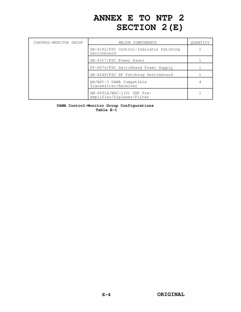
ANNEX E TO NTP 2SECTION 2(E)
CONTROL-MONITOR GROUP MAJOR COMPONENTS QUANTITY
SB-4182/FSC Control-Indicator PatchingSwitchboard
1
SB-4317/FSC Power Panel 1
PP-8074/FSC Switchband Power Supply 1
SB-4248/FSC RF Patching Switchboard 1
AN/WSC-3 DAMA CompatibleTransmitter/Receiver
4
AM-6691A/WSC-1(V) UHF Pre-amplifier/Diplexer/Filter
1
DAMA Control-Monitor Group Configurations Table E-1
E-4 ORIGINAL

ANNEX E TO NTP 2SECTION 2(E)
a. OK-454(V)/WSC Control-Monitor Group (SingleDAMA). The OK-454(V)/WSC is commonly referred to assingle DAMA since only one TD-1271B/U multiplexer isinstalled. The OK-454(V)/WSC will be installed on themajority of ships. A typical OK-454(V)/WSC installationis shown in figure E-1.
Figure E-1A Typical OK-454(V)WSC Installation
E-5 ORIGINAL

ANNEX E TO NTP 2SECTION 2(E)
b. OK-455(V)/WSC Control-Monitor Group (DualDAMA). The OK-455(V)/WSC is commonly referred to as dualDAMA since two TD-1271B/U multiplexers are installed.The OK-455(V)/WSC will only be installed on larger ships.A typical OK-455(V)/WSC installation is shown in figureE-2.
Figure E-2A Typical OK-455(V)/WSC Installation
E-6 ORIGINAL

ANNEX E TO NTP 2SECTION 2(E)
c. OK-481(V)2/FSC Control-Monitor Group. The OK-481(V)2/FSC is installed at the four NCTAMS and atNAVCOMMSTA Stockton, CA. A typical OK-481(V)2/FSCinstallation is shown in figure E-3.
Figure E-3A Typical OK-481(V)/FSC Installation
E-7 ORIGINAL
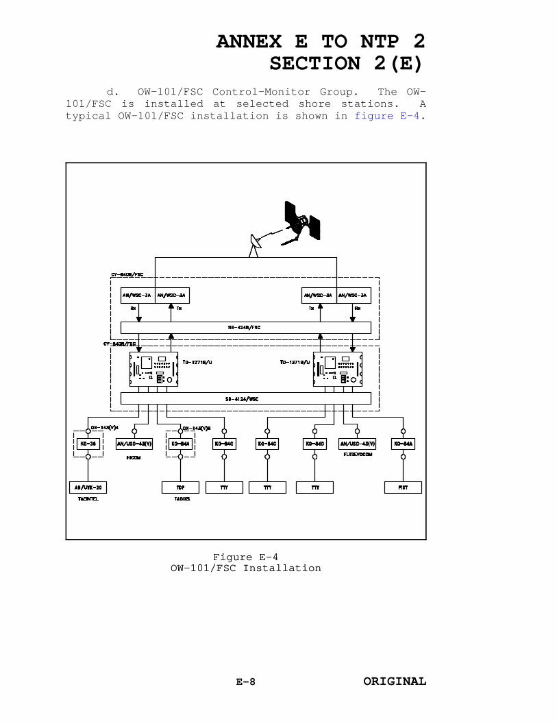
ANNEX E TO NTP 2SECTION 2(E)
d. OW-101/FSC Control-Monitor Group. The OW-
Figure E-4OW-101/FSC Installation
101/FSC is installed at selected shore stations. Atypical OW-101/FSC installation is shown in figure E-4.
Figure E-4OW-101/FSC Installation
E-8 ORIGINAL

ANNEX E TO NTP 2SECTION 2(E)
4. WAVEFORM STRUCTURE
Figure E-5Basic DAMA Frame Format
The UHF DAMA subsystem organizes the satellitechannel into frames which are 1.386 seconds in length.Each frame is subdivided into time slots as illustratedin figure E-5. The name and purpose of each slot type isas follows:
Figure E-5Basic DAMA Frame Format
a. Channel Control Orderwire (CCOW) Slot. TheCCOW time slot is used by the channel controller totransmit system timing and control information to thesubscriber units. It provides the subscriber units withinformation on the system timing, configuration, andcontrol of a particular satellite channel. The CCOWtransmission occurs at the beginning of each frame.
b. Return Channel Control Orderwire (RCCOW) Slot.The RCCOW time slot is used by the subscriber units totransmit information to the channel controller. Itpermits the subscriber units to request access to usertime slots and to respond to channel controllerinquiries.
c. Ranging Slot. The Ranging time slot is usedby the channel controller and the subscriber units todetermine the range (distance) to the satellite. Theslot allows each terminal to transmit and receive its owndata stream for the purpose of calculating the range tothe satellite, based on the round-trip delay time.Ranging is performed to establish transmitter
E-9 ORIGINAL

ANNEX E TO NTP 2SECTION 2(E)
synchronization with the UHF DAMA frame format.
d. Link Test Slot. The Link Test time slot isused by individual subscribers to evaluate theperformance of their satellite link. The subscriber isable to transmit a fixed data stream to the satellite,receive that bit stream, and then perform error analysis,automatically.
e. User Slot. The User time slots are used bysubscriber units to transmit or receive data. There arethree segments of time slots in each frame designated asA, B, and C. Segment A may contain from 1 to 5 discretetime slots, segment B may contain from 1 to 11 discretetime slots, and segment C may contain from 1 to 6discrete time slots. The number of discrete time slotsfor each segment depends on the baseband data rate, theforward error correction (FEC) coding rate, and thetransmission burst rate as influenced by the radiofrequency environment.
(1) For example, a given data time slot insegment A can support one circuit if the baseband datarate is 1200 bps, the FEC coding is at a rate of 3/4, andthe transmission burst rate is 19,200 symbols per second(sps). Another configuration of segment A can support 5circuits if all of the baseband data rates are 75 bps,the FEC coding is at a rate of 1/2, and the transmissionburst rate is 19,200 sps. Combinations of all possibleA, B, and C time slot segment configurations result inover 2500 selectable frame formats.
(2) Figure E-6 illustrates one typical frameformat that could be built when, for example, securevoice, Common User Digital Information Exchange Subsystemand Naval Modular Automated Communications Subsystem(CUDIXS and NAVMACS), tactical intelligence (TACINTEL),and teletypewriter (TTY) subsystem circuits aresimultaneously using the UHF DAMA subsystem. The datathat is to be transmitted is assigned a data slotequivalent to the capacity required to accommodate it.In the figure, the secure voice circuit with a basebanddata rate of 2400 bps is assigned one of the two 2400 bpsslots available and placed in segment B. The CUDIXS andNAVMACS circuit with a baseband data rate of 2400 bps isassigned the other 2400 bps slot, in segment C. TheTACINTEL circuit with a baseband data rate of 4800 bps isassigned the only 4800 bps slot, in segment B, and sixTTY circuits with baseband data rates of 75 bps each are
E-10 ORIGINAL
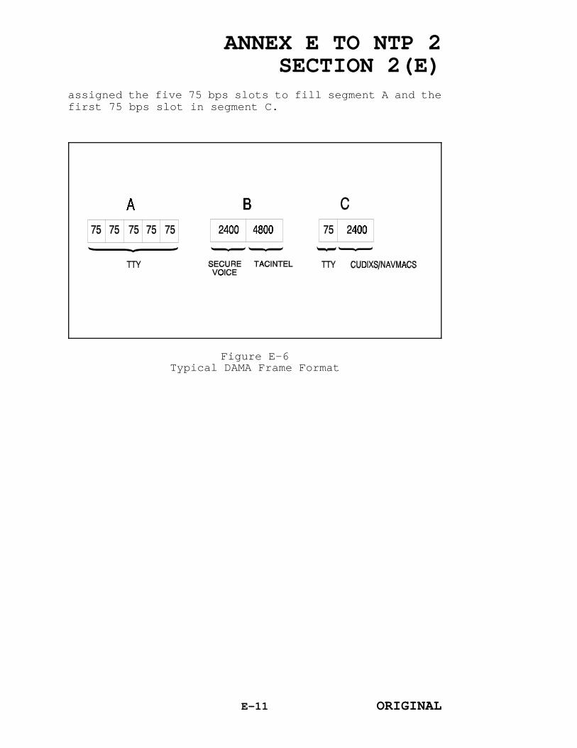
ANNEX E TO NTP 2SECTION 2(E)
assigned the five 75 bps slots to fill segment A and thefirst 75 bps slot in segment C.
Figure E-6Typical DAMA Frame Format
E-11 ORIGINAL
ANNEX E TO NTP 2SECTION 2(E)
5. MODES OF OPERATION
The UHF DAMA subsystem is designed to operate inthree modes: automatic control, semi-automatic control,and distributed control. In all modes of operation, oneof the DAMA terminals must be configured as the channelcontroller. The channel controller transmits informationon system timing, configuration, and control of aparticular satellite channel to the subscriber units andreceives requests for access to user time slots from thesubscriber units. The following paragraphs provide briefdescriptions of the modes of operation.
a. Automatic Control. In the automatic controlmode, the channel controller maintains a pool of usertime slots and dynamically assigns these time slots inresponse to user requests. The channel controller poolstime slots from one or more satellite channels. Useraccess requests are transmitted automatically by the userterminals via the RCCOW time slot and subsequent slotconnections are made automatically by the channelcontroller via the CCOW time slot. An Automatic DAMAController, which supports the automatic control mode andwhich supports the Communications Support System (CSS)and Copernicus Architectures, will be developed as afuture capability.
b. Semi-Automatic Control. In the semi-automaticcontrol mode, an operator at the channel controllerassigns user time slots in response to user requests. ASemi-Automatic DAMA Controller, which uses the semi-automatic control mode of the TD-1271B/U to allocate andcontrol the UHF DAMA subsystem resources, is beingdeveloped.
c. Distributed Control. In the distributedcontrol mode, pre-assigned, fixed frame formats and slotassignments for each satellite channel are used. Theframe format and slot assignment information, specifiedin appropriate communications directives, are enteredmanually at the channel controller and are transmitted bythe channel controller to the user terminals via the CCOWtime slot. Currently, the distributed control mode isthe only mode used.
6. CURRENT OPERATION
E-12 ORIGINAL

ANNEX E TO NTP 2SECTION 2(E)
a. For current UHF DAMA subsystem operation, asingle master control station is located within eachsatellite footprint. The master control stations arelocated at the four NCTAMS and at NAVCOMMSTA Stockton,CA. Multiple TD-1271B/U terminals are installed at eachmaster control station. Each TD-1271B/U can support upto four baseband circuits. During normal operations, theTD-1271B/U terminals at the master control stations areconfigured as the channel controllers. The channelcontroller performs all of the CCOW functions required bythe UHF DAMA subsystem for control of the satellitechannel.
b. The number of TD-1271B/U terminals installedaboard each ship varies according to the baseband circuitrequirements of the platform. Any DAMA-equipped platformwith full-duplex capability can be configured as thechannel controller. This capability permits shipboardterminals to act as alternate control stations providingan emergency backup function for the shore-based channelcontrollers.
c. Operationally, a user terminal has itsbaseband port automatically connected to a data time slotwhen the operator enters the proper slot number into thefront panel keypad of the TD-1271B/U. Each UHF SATCOMsubsystem that uses the UHF DAMA subsystem has a specificslot number (i.e., data time slot) assigned for thatsubsystem. The circuits are generally operated on anetted basis. The circuit numbers used by the operatorsare assigned by the Fleet Commander in Chief. This modeof operation is referred to as the distributed controlmode.
d. The UHF DAMA subsystem appears transparent tothe user subsystems. Once all of the equipment isinstalled and the initialization procedures arecompleted, the precedence level for network transmissionsand the five-digit call number for the network areentered at the front panel keypad of the TD-1271B/U. Thecircuit connect is made automatically, provided thecircuit number entered is contained within the currentframe format for the channel on which the subscriber isoperating. In practice, once the link is established,the operator will not have to repeat these procedures,since most subsystem networks are in use on a continuous
E-13 ORIGINAL

ANNEX E TO NTP 2SECTION 2(E)
basis.
e. Users equipped with AN/WSC-3A's are capable ofoperating with one transceiver per TD-1271B/U (i.e., inthe half-duplex mode) since the AN/WSC-3A can rapidlyshift between the satellite uplink and downlinkfrequencies. However, the AN/WSC-3A is unable to receivedata in one time slot and transmit data in the nextadjacent time slot, since a certain amount of time isrequired for the transmitter to reach full power prior totransmitting data. Because the receiver and transmitterwould have to simultaneously access the DAMA channel toreceive and then transmit data in adjacent time slots,the condition is referred to as "contention". Thepossibility of contention problems can be eliminated bycareful operator selection of the DAMA frame format. Amore detailed explanation of DAMA contention and frameformat selection may be found in the UHF DAMA Operator'sHandbook (Shore) (FSCS-211-84-2A), and the UHF DAMAOperator's Handbook (Shipboard) (FSCS-211-84-1A).
7. TRANSITION
a. Transition Plan. To minimize the impact onfleet operations, the transition of UHF SATCOM subsystemsto the UHF DAMA subsystem was planned in four phases.During Phase I, TACINTEL, Fleet Imagery Support Terminal(FIST), Fleet Secure Voice Communications (FLTSEVOCOM),and restricted secure voice networks (i.e., High Command,Battle Group Secure Voice, Commander in Chief privacy,etc.) were transitioned to the UHF DAMA subsystem.During Phase II, Tactical Data Information ExchangeSubsystem A (TADIXS A) was transitioned to the UHF DAMAsubsystem. During Phases III and IV, CUDIXS and NAVMACS,Submarine Satellite Information Exchange Subsystem(SSIXS), and Officer in Tactical Command InformationExchange Subsystem II (OTCIXS II) will be transitioned tothe UHF DAMA subsystem.
E-14 ORIGINAL

ANNEX E TO NTP 2SECTION 2(E)
b. DAMA/Non-DAMA Interoperability. Thetransition of most UHF SATCOM subsystems to the UHF DAMAsubsystem is taking place so that subscribers that havebeen converted to the UHF DAMA subsystem can communicatewith subscribers that have not yet been converted.Equipment installed at the shore-based master controlstations provides an interface between the DAMA and non-DAMA capable subscribers.
E-15 ORIGINAL

ANNEX F TO NTP 2SECTION 2(E)
ANNEX F
SUBMARINE SATELLITE INFORMATION EXCHANGE SUBSYSTEM II
(SSIXS II)
1. INTRODUCTION
This annex provides a description of SSIXS II,discusses its operational applications, and presentsdetailed information on subsystem operation. Since theintroduction of SSIXS, shore sites have received a majorenhancement and are now referred to as SSIXS II.However, the equipment installed in the submarinesremains the initial SSIXS.
2. SSIXS II
a. SSIXS was designed to complement existing verylow frequency (VLF), low frequency, medium frequency, andhigh frequency communication links between shore-basedsubmarine Broadcast Control Authorities (BCA's) andsubmarines (see figure F-1).
b. The subsystem provides the submarine commanderwith the capability to receive messages transmitted viasatellite at scheduled intervals (Group Broadcasts).Between Group Broadcasts, submarines may transmitmessages to the BCA, including a request for any messagesheld in queue. The shore terminal responds to thesetransmissions with acknowledgements for the individualmessages just received, and transmits all messages heldthat are addressed to the querying submarine. Theavailability of two modes of operation, Group Broadcastand Query and Response, permits the choice of whether tobe active or passive at the discretion of the submarinecommander. A single SSIXS network may have up to 120submarine subscribers. A single network may beestablished on more than one satellite (e.g., when theoperating area under the cognizance of a BCA extendsbeyond the footprint of a single satellite), or two BCA'smay share a single satellite channel by offsetting thetime of their respective Group Broadcast transmissions.
c. The SSIXS II baseband equipment installed atthe BCA locations ashore performs dual functions. SSIXSII:
F-1 ORIGINAL

ANNEX F TO NTP 2SECTION 2(E)
(1) Accepts messages for delivery to
Figure F-1SSIXS
submarines via satellite or VLF paths, and receivesmessages from submarines via the satellite path foronward delivery.
F-2 ORIGINAL
ANNEX F TO NTP 2SECTION 2(E)
(2) Provides the shore SSIXS II operator withthe capability to compose and control the VLF VERDINbroadcasts by an interface with the Integrated SubmarineAutomated Broadcast Processing System.
d. The SSIXS subscriber terminals afloat performthe complementary operations necessary to permitreception of Group Broadcasts or conduct Query andResponse functions.
3. MESSAGE TRAFFIC INPUT
At the BCA, messages, addressed to submarines,that have been received from Automatic Digital Network(AUTODIN), Naval Communications Processing and RoutingSystem, or locally over-the-counter in the message centerare entered into the SSIXS II shore terminal manually, byusing the Submarine Message Automated Routing Terminal(SMART) or by high-speed paper tape reader. Aboard thesubmarine, the message traffic is input via theteletypewriter or tape reader equipment. Nuclear poweredattack submarines (SSN's) that have the Data Link ControlSystem installed have an additional input and outputcapability via the sensor interface unit for over-the-horizon targeting (OTH-T) messages. (OTH-T messages aresegregated in SSIXS II by the presence of a unique two-character (OH) message indicator code in the SSIXS IImessage format.)
4. RADIO FREQUENCY (RF) TRANSMISSION (LINK CONTROL)
Ashore, the SSIXS II subsystem shares access tothe same satellite RF terminal equipment at the NavalComputer and Telecommunications Area Master Station(NCTAMS) as other ultra high frequency (UHF) satellitecommunications (SATCOM) subsystems, with the exception ofCommander Submarine Group SEVEN (COMSUBGRU 7), Yokosuka,Japan, which is equipped with dedicated AN/WSC-3transceivers. Since each BCA is remotely located fromthe NCTAMS, line modems and land lines are required forinterconnection. The submarine UHF RF terminal is thesingle-channel, half-duplex AN/WSC-3(V)2. SSIXS IItransmissions are at the 4800 bits per second rate.Compatibility with demand assigned Multiple access hasbeen successfully demonstrated and may be employed in thefuture. Essentially all SSN's are being equipped withdual SATCOM installations to permit simultaneous SATCOMand line of sight operations, simultaneous participation
F-3 ORIGINAL

ANNEX F TO NTP 2SECTION 2(E)
in additional satellite networks (e.g., Officer inTactical Command Information Exchange Subsystem (OTCIXS),Secure Voice), and for redundancy.
5. MESSAGE TRAFFIC RECEPTION
Each subscriber to a SSIXS II network is assigneda unique subscriber identification (ID) number, which isused in all transmissions to or from the subscriber. TheID numbers are stored within the shore station andsubscriber processors. The application of these numberstakes many forms as shown below.
a. At the shore stations, the ID number, whencombined with broadcasts, will determine the number oftimes message traffic is transmitted to a subscriber.
b. In the event a submarine subscriber transmitsto the shore station, this identifying number will beincluded in the transmission. If the number is notincluded, the shore station cannot acknowledge thetransmission.
c. The ID number is used at subscriber terminalsto screen broadcast transmissions for message trafficdirected to the subscriber. The remaining data in thetransmission is discarded. In the link control protocolemployed by SSIXS II, the broadcast of message trafficdoes not require an acknowledgment by the subscriber.
6. SPECIAL INTELLIGENCE (SI) SSIXS II
In addition to the general service (GENSER) SSIXSII subsystems described above, an additional SSIXS IIcapability, dedicated to SI communications and designatedSI SSIXS II, is installed at all shore sites. SI SSIXSII is functionally similar to GENSER SSIXS II.
7. EQUIPMENT CONFIGURATION
Table F-1 lists the equipment used in SSIXS II.
a. Shore-based Link Control and MessageProcessing AN/FSQ-163
F-4 ORIGINAL

ANNEX F TO NTP 2SECTION 2(E)
Shore-based LinkControl and MessageProcessing AN/FSQ-163
Processor AN/FYK-29
Interconnecting Group (IG) ON-143(V)4/USQ
Reproducer (magnetic tape) RP-357/FSQ
Magnetic Disk Memory Unit MU-851
Operator Workstation IP-1660/FSQ
System Console TT-835/U
Submarine Message AutomatedRouting Terminal (SMART)
AN/FYK-33
Recorder-Reproducer(perforated tape)
RD-397B(V)3/U
Patch Panel SB-4325/FSQ
Cryptographic Equipment KG-36 or 35
Line Modems CODEX LSI4800
Modem Sharing Units CODEX MSU-7012
Subscriber(Submarine) TerminalMessage Processing
IG ON-143(V)5/USQorON-143(V)6/USQ
Cryptographic Equipment KG-36
Teletypewriter AN/UGC-20BorUGC-136AX
Keyboard Punch TT-253/UG
Converter, Audio Digital (notpart of SSIXS II)
CV-333/U
RF Terminal,SubscriberInstallation
Transceiver, UHF AN/WSC-3
NOTE:Shore based list of equipment is applicable to an installationat a submarine operations control center. The NAVCOMPARS or theAUTODIN network may pass message traffic for processing by SSIXSII; however, these systems interface with SSIXS II through SMARTand have not been included in this listing.
SSIXS II EquipmentTable F-1
8. SSIXS II INSTALLATIONS
F-5 ORIGINAL

ANNEX F TO NTP 2SECTION 2(E)
The subscriber terminals are installed in nuclearpowered fleet ballistic missile submarine (SSBN) and SSNtype submarines. The shore terminal installations arelisted in the table F-2.
ORGANIZATION LOCATION
COMSUBGRU 7 Yokosuka, Japan
COMSUBGRU 8 Agnano, Italy
COMSUBGRU 10 Kings Bay, GA
COMSUBPAC Pearl Harbor, HI
COMSUBLANT Norfolk, VA
SSIXS II Shore LocationsTable F-2
9. OPERATION
The following references provide detailed operationsprocedures for SSIXS.
a. SCOM-MAN-SXS-S20/U-R01C0 Computer Systems Operation andSupport Manual for The Submarine Satellite Information ExchangeSubsystem II (SSIXS II) Shore dated 30 September 1990.
b. SOM(P)-6436 System Operator's Manual for SSIXS(ON-143(V)5 Subscriber) dated 1 April 1986.
c. SOM(P)-6442 System Operator's Manual for SSIXS(ON-143(V)6 Subscriber) dated 6 August 1985.
F-6 ORIGINAL

ANNEX G TO NTP 2SECTION 2(E)
ANNEX G
FLEET IMAGERY SUPPORT TERMINAL (FIST)
1. INTRODUCTION
This annex provides information on theoperation and management of the FIST system. Theseprocedures provide Naval Computer and TelecommunicationsCommand (NAVCOMTELCOM) and Naval Security Group personnelwith guidelines to ensure mutual understanding of eachorganization's role in the daily operation of the FISTsystem.
2. BACKGROUND
FIST is a multifunction digital imagerytransmission and processing system. The system providesfunctions which support the exploitation, transmission,receipt, storage, and retrieval of digital images. FISTalso allows for annotation and production of hard copyimages. Figure G-1 illustrates a fundamental FISTsatellite functional circuit. Using the exploitationfunctions, the image can be enhanced in a variety of waysto facilitate the intelligence specialist'sinterpretation tasks. The system transmits and receivesimages and/or text over existing secure militarycommunications channels.
3. FIST SYSTEM ARCHITECTURE
a. Figure G-2 illustrates a FIST ultra highfrequency (UHF) satellite communications (SATCOM) shoreand afloat configurations with the demand assignedMultiple access (DAMA) capability. The FIST shoreconsole illustrated in figure G-2 is comprised ofassemblies and sub-assemblies, a power panel, two diskdrives, high resolution monitor, message display,trackball, keyboard, controller and processor, hard copyunit, print tray, exhaust fan, connector panel, andsystem cabling. The following paragraphs describe thecomponents of the FIST console functional block diagramillustrated in figure G-3.
b. The FIST has two disk drives which are used toload and store information onto floppy diskettes. Thisinformation includes the FIST Operating System andimages. Under normal conditions, disk A is used to load
G-7 ORIGINAL
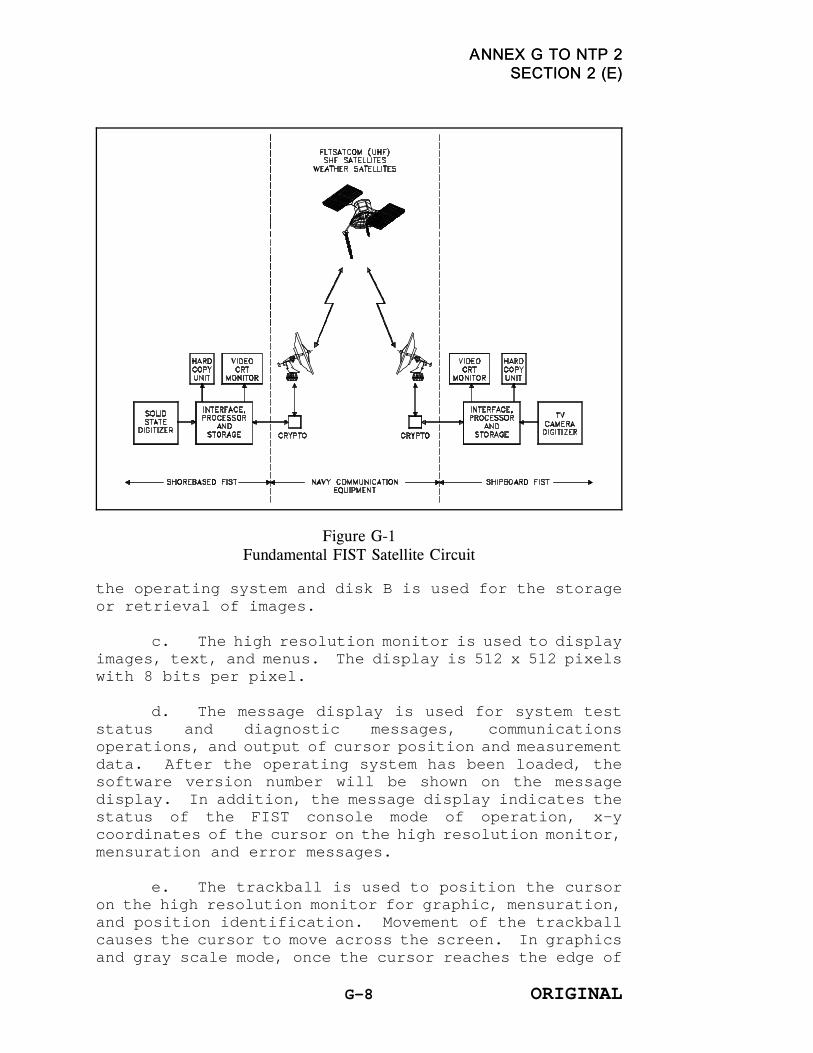
ANNEX G TO NTP 2ANNEX G TO NTP 2SECTION 2 (E)SECTION 2 (E)
the operating system and disk B is used for the storage
Figure G-1Fundamental FIST Satellite Circuit
or retrieval of images.
c. The high resolution monitor is used to displayimages, text, and menus. The display is 512 x 512 pixelswith 8 bits per pixel.
d. The message display is used for system teststatus and diagnostic messages, communicationsoperations, and output of cursor position and measurementdata. After the operating system has been loaded, thesoftware version number will be shown on the messagedisplay. In addition, the message display indicates thestatus of the FIST console mode of operation, x-ycoordinates of the cursor on the high resolution monitor,mensuration and error messages.
e. The trackball is used to position the cursoron the high resolution monitor for graphic, mensuration,and position identification. Movement of the trackballcauses the cursor to move across the screen. In graphicsand gray scale mode, once the cursor reaches the edge of
G-8 ORIGINAL

ANNEX G TO NTP 2ANNEX G TO NTP 2SECTION 2 (E)SECTION 2 (E)
the screen, further movement of the trackball toward thatedge has no effect on the displayed image. The graystretch function, Key 19 on the keyboard, allows thecontrast and brightness of an image to be adjusted bysimply positioning the cursor (left to right adjustcontrast and top to bottom adjusts brightness). Startingpoints for graphics and mensuration functions are alsoset using the trackball.
Figure G-2FIST UHF SATCOM Shore/Afloat Configurations
G-9 ORIGINAL

ANNEX G TO NTP 2ANNEX G TO NTP 2SECTION 2 (E)SECTION 2 (E)
Figure G-3Functional Block Diagram
G-10 ORIGINAL

ANNEX G TO NTP 2ANNEX G TO NTP 2SECTION 2 (E)SECTION 2 (E)
4. NAVAL COMPUTER AND TELECOMMUNICATIONS AREA MASTER
STATION (NCTAMS) AND FLEET TELECOMMUNICATIONS
OPERATION CENTER (FTOC) CONTROL OF FIST
Fleet Satellite Communications (FLTSATCOM) accessfor FIST is arranged by the Fleet Commanders in Chief(FLTCINC's) through the supporting NCTAMS as part ofestablished UHF SATCOM channel assignment allocationplans. The NCTAMS's perform net control station andsatellite control functions for FLTSATCOM operations. TheFTOC informs Commander Naval Computer andTelecommunications Command (COMNAVCOMTELCOM) and therespective FLTCINC of the operational status of thetelecommunications systems within the assignedcommunications area.
5. FIST OPERATIONS
a. FIST is a shore-ship-shore UHF SATCOM securesystem which provides classified imagery to afloat units.The system is first set up in the secure voice mode forthe FIST broadcast station to establish communicationswith participating afloat units. The FIST shore stationthen transmits an imagery broadcast to participatingunits. After the broadcast is complete, the shore FISTwill revert back to secure voice and receiveacknowledgements or requests for repetition from allparticipating units.
b. There are three transmit and receive modes ofoperation for FIST.
(1) The first method is the HANDSHAKE modewhich requires the receiving terminal to acknowledgereceipt of the imagery transmission with the sendingsite.
(2) The second method is the BROADCAST modewhich does not require the receiving site to acknowledgereceipt of the image.
(3) The third method is the EAVESDROP modewhich is receive only and allows the receive terminal to"listen in" on a transmission between two otherterminals.
G-11 ORIGINAL

ANNEX G TO NTP 2ANNEX G TO NTP 2SECTION 2 (E)SECTION 2 (E)
c. Images are stored or transmitted in either acompressed or an uncompressed format. The compressionalgorithm enables the reduction in both transmission timeand storage capacity requirements without degradation ofessential elements of information.
G-12 ORIGINAL

ANNEX I TO NTP 2SECTION 2(E)
ANNEX I
ACRONYMS
AAWC Anti-Air Warfare CommanderABCS Alternate Broadcast Control
StationAC alternating currentACK acknowledgementACP Allied Communications
PublicationAFSATCOM Air Force Satellite
CommunicationsAIG address indicating groupAIRTERM airborne terminalAJ antijamAM amplitude modulationANDVT Advanced Narrowband Digital
Voice TerminalARQ automatic report requestASUWC Anti-surface Warfare
CommanderASW antisubmarine warfareASWC Antisubmarine Warfare
CommanderATLCF Alternate TACINTEL Link
Control FacilityATP Advanced Tracer PrototypeATSM Automated TRAP Status
MessagesAUTODIN Automatic Digital NetworkAZ azimuth
BCA Broadcast Control AuthorityBCS Broadcast Control StationBGPHES Battle Group Passive
Horizon Extension SystemBOM bit-oriented messagebps bits per secondBPU buffer processing unitBW bandwidth
C2 command and control C3 command, control, and
communicationsC4I command, control,
communications, computers
I-1 ORIGINAL

ANNEX I TO NTP 2SECTION 2(E)
and intelligenceCARP communications alternate
routing planCCC CINC (Commander in Chief)
Command ComplexCCOW channel control orderwireCCS MK II Combat Control System Mark
IICCSC Cryptologic Combat Support
ConsoleCCSS Cryptologic Combat Support
SystemCDPS Communication Data
Processing SystemCES Coast Earth StationCG, FMF Commanding General, Fleet
Marine ForcesCG, MCCDC Commanding General, Marine
Corps Combat DevelopmentCenter
CIB Communications InformationBulletin
CIC Combat Information CenterCINC commander in chiefCINCLANTFLT Commander in Chief, U.S.
Atlantic FleetCINCPACFLT Commander in Chief, U.S.
Pacific FleetCINCUSNAVEUR Commander in Chief, U.S.
Naval Forces EuropeCJCS Chairman of the Joint
Chiefs of StaffCMC Commandant of the Marine
CorpsCNO Chief of Naval OperationsCO commanding officerCOCC Contractor Operations
Control Center COMMPLAN communications planCOMMSHIFT communications shiftCOMNAVCOMTELCOM Commander, Naval Computer
and TelecommunicationsCommand
COMNAVSPACECOM Commander, Naval SpaceCommand
COMSAT Communications SatelliteCOMSEC communications securityCOMSPAWARSYSCOM Commander, Space and Naval
I-2 ORIGINAL

ANNEX I TO NTP 2SECTION 2(E)
Warfare Systems CommandCOMSPOT communications spot reportCOMSUBGRU Commander Submarine GroupCOMSUBLANT Commander Submarine Force,
U.S. Atlantic FleetCOMSUBPAC Commander Submarine Force,
U.S. Pacific FleetCONUS continental United States COTR Contracting Officer's
Technical RepresentativeCOTS commercial off-the-shelfCRT cathode-ray tubeCSG Cryptologic Support GroupCSOC Consolidated Space
Operations CenterCSS Communications Support
SystemCUDIXS Common User Digital
Information ExchangeSubsystem
CV aircraft carrierCWC Composite Warfare Commander
DAMA Demand Assigned MultipleAccess
dBW decibel referenced to onewatt
dc direct currentDCS Defense Communications
SystemDISA Defense Information Systems
AgencyDOD Department of Defense DPS data processing setDPSK differential phase shift
keyingDSCS Defense Satellite
Communications SystemDSN Defense Switched NetworkDSSCS Defense Special Security
Communications SystemDTC-2 Desktop Tactical Computer 2
EC earth coverageEAM emergency action messageEASTPAC Eastern PacificEHF extremely high frequency
I-3 ORIGINAL

ANNEX I TO NTP 2SECTION 2(E)
EIRP effective isotropicradiated power
EL elevationEMCON emission controlESM electronic warfare support
measuresESS Electronic Support SquadronET earth terminalETR estimated time of return
FDMA frequency division multipleaccess
FDOA frequency difference ofarrival
FEC forward error correctionFIST Fleet Imagery Support
TerminalFLTBCST fleet broadcastFLTCINC Fleet Commander in ChiefFLTRACEN Fleet Training CenterFLTSAT Fleet SatelliteFLTSATCOM Fleet Satellite
CommunicationsFLTSEVOCOM Fleet Secure Voice
CommunicationsFM frequency modulationFMF Fleet Marine ForceFOSIF Fleet Ocean Surveillance
Information FacilityFSK frequency shift keyingFSM FLTSATCOM Spectrum MonitorFTOC Fleet Telecommunications
Operations CenterFTP Fleet Telecommunications
Procedures
G/T receive gain-to-noisetemperature
GENSER general serviceGLOBIXS Global Information Exchange
SystemGOFR Geolocation of Radio
Frequency Interference(RFI)
GSCS Government SatelliteControl Station
HCSI Hughes Communications
I-4 ORIGINAL

ANNEX I TO NTP 2SECTION 2(E)
Services, IncorporatedHF high frequencyHFDF high frequency direction
findingHICOM high commandHQMC Headquarters, Marine CorpsHSFB High Speed Fleet Broadcast
I/O input/outputI&W indication and warningsID identificationIF intermediate frequencyIFSM Interim FLTSATCOM Spectrum
MonitorIG Interconnecting GroupIMMIS Integrated MILSATCOM
(Military Satellite Communications) Management
Information SystemINMARSAT International Maritime
SatelliteIO Indian OceanIOC initial operational
capability IR infraredISABPS Integrated Submarine
Automated BroadcastProcessing System
ISDB Integrated SATCOM(Satellite Communications)Database
ISN internal sequence numberIXS Information Exchange
Subsystem
JCS Joint Chiefs of StaffJCSC Joint Communications
Satellite Center
JIC Joint Intelligence CenterJMPA Joint MILSATCOM Panel
Administrator
kbps kilobits per secondkHz kilohertz
LAN local area networkLANT Atlantic
I-5 ORIGINAL

ANNEX I TO NTP 2SECTION 2(E)
LEASAT Leased SatelliteLES Lincoln Experimental
SatelliteLF low frequencyLFT&RS Landing Force Transmit andReceive SubsystemLIMDIS limited distributionLNA low noise amplifier LOS line of sightLRM low rate multiplexerLSR link status report
MAGTF HQ Marine Air Ground TaskForce Headquarters
MARISAT Maritime SatelliteMB megabitsMED MediterraneanMF medium frequencyMHz megahertzMIJI meaconing, intrusion,
jamming and interference MILSATCOM military satellite
communicationsMINTERM miniaturized terminalMOA memorandum of agreementMODEM modulator/demodulatorMOP memorandum of policyMPDS Message Processing and
Distribution SystemMSO MILSATCOM Systems
OrganizationMSO Mine Sweeper OceanMU message unitMUS mission unique softwareMUSIC multi-user special
intelligence communications
NAK negative acknowledgementNATO North Atlantic Treaty
Organization NAVCOMMAREA Naval Communications AreaNAVCOMMSTA Naval Communications
StationNAVCOMPARS Naval Communications
Processing and RoutingSystem
NAVCOMTELCOM Naval Computer andTelecommunications Command
I-6 ORIGINAL

ANNEX I TO NTP 2SECTION 2(E)
NAVCOMTELSTA Naval Computer andTelecommunications Station
NAVIXS Navy Information ExchangeSystem
NAVMACS Naval Modular AutomatedCommunications Subsystem
NAVPUBFORMCEN Naval Publications andForms Center
NAVSATCOMMFAC Naval SatelliteCommunications Facility
NAVSECGRU DET Naval Security GroupDetachment
NAVSECGRUACT Naval Security GroupActivity
NAVSOC Naval Space OperationsCenter
NAVSPOC Naval Space CommandOperations Center
NAVTECHTRACEN Naval Technical TrainingCenter
NCA National CommandAuthorities
NCO net control officerNCS network control stationNCTAMS Naval Computer and
Telecommunications AreaMaster Station
NCTS Naval Computer andTelecommunications System(or Station)
NDRO non-destructive read-onlyNECOS net control stationNiCd nickel cadmium NITF National Imagery
Transmission FormatNSCS Navy Satellite Control
StationNTCS-A Navy Tactical Command
Systems AfloatNTP Naval Telecommunications
ProceduresNWP Naval Warfare Publication
OBU Ocean SurveillanceInformation System BaselineUpgrade
OMFCU outboard message formatconversion unit
I-7 ORIGINAL

ANNEX I TO NTP 2SECTION 2(E)
OPELINT operational electronicintelligence
OPINTEL operational intelligenceOPSCOMM operator communicationsOPSEC operations securityOSIS Ocean Surveillance
Information SystemOTCIXS Officer-in-Tactical Command
Information ExchangeSubsystem
OTH-T over-the-horizon targetingOTO operator-to-operator
PAC PacificPCC Primary Control CenterPHM patrol hydrofoil missilesPOC point of contactPOCG Program Operations
Coordination GroupPOST Prototype Ocean
Surveillance TerminalPQS personnel qualification
standardsPSK phase shift keying
RATS random access time slotRCCOW return channel control
orderwireRDF radio direction findingRDIXS Research and Development
Information Exchange SystemRDT&E research, development,
test, and evaluationRF radio frequencyRFI radio frequency
interferenceRISC reduced instruction set
computerRPM revolutions per minuteRx receive
SATCOM satellite communicationsSCT single channel transponderSDS Satellite Data SystemsSDT scheduled downtimeSECVOX secure voiceSERVSCOLCOM Service School CommandSES ship earth station
I-8 ORIGINAL

ANNEX I TO NTP 2SECTION 2(E)
SEW Space and ElectronicWarfare
SEWC Space and ElectronicWarfare Commander
SGLS Space-Ground Link System SGT satellite ground terminalSHF super high frequency SI special intelligenceSID subscriber identification
numberSIGINT signal intelligenceSIOP Single Integrated
Operational Plan SMART Submarine Message Automated
Routing TerminalSNR signal-to-noise ratioSOL sequence order listSPS symbols per secondSRWI satellite radio wireline
interfaceSSA SATCOM signal analyzerSSBN nuclear powered fleet
ballistic missile submarineSSES Ship's Signals Exploitation
SpaceSSIXS Submarine Satellite
Information ExchangeSubsystem
SSN nuclear powered attacksubmarine
SSS System Supervisor StationSTU-III Secure Telephone Unit,
Third GenerationSTWC Strike Warfare CommanderSUPPLOT supplementary plot
TACINTEL Tactical IntelligenceSubsystem
TACSAT-1 Tactical CommunicationsSatellite-1
TACSATCOM tactical satellitecommunications
TACTERM tactical terminalTADIXS Tactical Data Information
Exchange SubsystemTADIXS A Tactical Data Information
Exchange Subsystem ATCC Tactical Command Center
I-9 ORIGINAL

ANNEX I TO NTP 2SECTION 2(E)
TCC Transmission Control CodesTDM time division multiplexTDMA time division multiple
accessTDOA time difference of arrivalTDP tactical data processorTDPCON TDP Controller TFS traffic flow securityTGF TADIXS A Gateway FacilityTLC TACINTEL Link ControlTLCF TACINTEL Link Control
FacilityTOED TRAP Operational
Exchange/DirectiveTRAP BCST Tactical Related
Applications BroadcastTRE Tactical Receive EquipmentTSM TRAP System MonitorTSR Telecommunications Service
RequestTSR traffic statistics reportTSR TRAP status reportTT&C telemetry, tracking, and
command TTY teletypewriterTU transmission unitTWCS TOMAHAWK Weapons Control
SystemTx transmit
U&S unified and specifiedUFO UHF Follow-onUHF ultra high frequency UK United KingdomURDB User Requirements DatabaseUSCINCSPACE Commander in Chief, U.S.
Space CommandUSCINCCENT Commander in Chief, U.S.
Central CommandUSN U.S. NavyUSNS U.S. Naval Service
VERDIN submarine multi-channelbroadcast system
VFCT voice/variable frequencycarrier telegraph
VHF very high frequencyVLF very low frequency
I-10 ORIGINAL

ANNEX I TO NTP 2SECTION 2(E)
VME Versamodule Eurocard
WESTPAC Western Pacific
I-11 ORIGINAL

ANNEX J TO NTP 2SECTION 2(E)
ANNEX J
GLOSSARY
Antijam (AJ) - The equipment, processes, or techniquesused to reduce the effects of jamming of a desired radiofrequency (RF) signal.
Asynchronous Transmission - A transmission in which eachcharacter or symbol is synchronized individually, usuallyby the use of start and stop bits (i.e., teletypewritersignals).
Azimuth - An angular measurement of direction in degreesfrom a known reference (e.g., true North).
Bandwidth - The range of frequencies over which anamplifier or receiver will respond and provide a usefuloutput.
Baseband - The band of frequencies occupied by theaggregate of the transmitted signals used to modulate acarrier, before they combine witha carrier in themodulation process.
Binary Phase Shift Keying (BPSK) - A method of modulationthat allows the instantaneous phase of the carrier toremain unchanged or shifted 180o. Bit - Abbreviation for binary digit (1 and 0).
Bit Error Ratio (BER) - The total number of incorrectbinary (Bit) values divided by the total number of binaryvalues transmitted, received, or processed over a circuitor system during a specified time period (e.g., 1 x 10⁻⁵
BER).
Bit Stuffing - A method of synchronizing two or more bitstreams (channels) that do not have the same bit rates,by inserting additional noninformational bits to cause abit-rate match of the channels (i.e., to cause twochannels to operate at 4800 bits vice one channel at 4800and the other at 2400 bits).
Burst Transmission - A radio transmission in which theinformation is stored and then released at 10 to 100 ormore times faster than the normal speed (usually noted insymbols per second (sps)). The received signals are
J-1 ORIGINAL

ANNEX J TO NTP 2SECTION 2(E)
recorded and then processed at normal speeds.
C-band - The radio frequency band between 3.9 and 6.2gigahertz (GHz).
Carrier - The constant RF which may be modulated bychanging the amplitude, frequency, or phase.
Communications Security (COMSEC) - The protectionresulting from all measures designed to deny unauthorizedpersons information of value which might be derived fromthe possession and study of telecommunications.
Cross Polarization - The use of different electronicpolarizations (normally right hand and left hand) of thesatellite uplink and downlink frequencies. Crosspolarization is affected by polarization of the antenna.
Demand Assigned Multiple Access (DAMA) - An access schemein which access to a channel by geographically separatedcommunications terminals is allocated on user demand.
Despun Antenna - A satellite antenna mounted on aplatform rotating counter to and at the same angularvelocity as the spinning satellite, thus maintaining afixed antenna orientation.
Differential Phase Shift Keying (DPSK) - A method ofencoding each element of a signal for transmission as achange in the phase of the carrier with respect to itsprevious phase angle.
Digital Interface - A common connection for sharinginformation in a binary form.
Downlink - A transmission link carrying information froma satellite to earth.
Diplexer - A frequency-dependent device that may be usedto separate or combine signals.
Down-converter - A device which translates frequencies sothat the output frequencies are lower than the inputfrequencies.
Drift - The slow undesired movement of a satellite fromits intended position.
J-2 ORIGINAL

ANNEX J TO NTP 2SECTION 2(E)
Duplex Circuit - A communications circuit that allowseach end user to simultaneously transmit and receiveinformation.
Earth Terminal (ET) - The earth portion of a satellitelink that receives, processes, and transmits satellitecommunications.
Effective Isotropic Radiated Power (EIRP) - The increasein radiated signal relative to an isotropic radiator (aradiation that has the same values along axes in alldirections). The gain in signal is due to the net gainof the transmitting antenna.
Elevation - An angular measurement in a vertical planemeasured in degrees from the horizon. The height towhich something is elevated above a point of reference,such as the ground.
Ephemeris Data - The position of a satellite orspacecraft in space with respect to time.
Extremely High Frequency (EHF) - The frequency bandextending from 30 to 300 GHz.
Frequency Division Multiple Access (FDMA) - The use offrequency division to provide multiple and simultaneoustransmissions to a single transponder.
Frequency Shift Keying (FSK) - A frequency modulationtechnique in which the modulating wave shifts the outputfrequency between predetermined values. The Navystandard shift is 170 Hz between center frequencies.
Geosynchronous (Geostationary) Satellite - An earthsatellite whose period of revolution is equal to theperiod of rotation of the Earth about its axis. In thatthe satellite position is relatively stationary to apoint on the Earth's surface, such a satellite may alsobe known as geostationary.
Guard Band - The unused frequency band between twosatellite transponder channels which provides a margin ofsafety against mutual interference.
High Frequency (HF) - The frequency band extending from3 to 30 MHz.
J-3 ORIGINAL

ANNEX J TO NTP 2SECTION 2(E)
Interconnect Facility (ICF) - A facility where one ormore communication links used to provide local areaservice between or among several locations which, takenas a whole, form a node in the network.
Jamming (or jamming signals) - The intentionaltransmission of radio signals in order to interfere withthe reception of signals from another station,particularly used in electronic countermeasures.
Ku-band - The frequency band between 15.35 and 24.50 GHz.
Look Angle - The angle, relative to the earth's surface,at which a satellite antenna is pointing at thesatellite.
Modulation - The process of varying or modifying thecharacteristics of a frequency (carrier) so that itvaries in step with the intelligence or data,superimposing information on an RF carrier wave.
Multiple Access - In satellite communications, thecapability of more than one terminal to use the samesatellite channel at any given time.
Multiplexing - The process of combining several signalsor inputs for transmission over the same circuit.
Node - A terminal of any branch of a network; or aterminal common to two or more branches of a network.
Orderwire - A circuit used by operating personnel tocoordinate the establishment, operation, maintenance, andcontrol of communication facilities.
Payload - The spacecraft communications package.
Phase Shift Keying (PSK) - A method of modulation inwhich the carrier is varied in relation to a referencephase or the phase of the previous signal.
Polarization - The process of making radiation vary overtime in direction and amplitude. The variation isperpendicular to the ray in a definite form.
Pulse-code Modulation (PCM) - The form of modulationwhich sequentially samples, quantizes, and codes amodulated signal into a binary form for transmission over
J-4 ORIGINAL

ANNEX J TO NTP 2SECTION 2(E)
a digital link.
Random Noise - Noise consisting of a large number oftransient disturbances with a statistically random timedistribution.
Satellite Constellation - The satellites in a commonorbit used by a SATCOM system.
SHF Band - The super high frequency band between 3 and 30GHz.
Sidelobe - A portion of the beam from an antenna, otherthan the main lobe. It is usually much smaller than themain lobe.
Solar Array - A group of interconnected solar cells thatconvert solar energy directly into electrical energy.
Spin-stabilization - A method of partially stabilizing acylindrical-form satellite by imparting a spin ofapproximately 60 revolutions per minute (rpm) along themajor axis.
Spread Spectrum Modulation - A communication andmodulation technique that makes use of sequential noise-like signals to spread the normal narrowband informationover a relatively wide band of frequencies to protectagainst jamming.
Stationkeeping - The process of keeping a satellite inits assigned orbital location.
Submarine Satellite Information Exchange Subsystem(SSIXS) - SSIXS is a shore-ship, ship-shore, and ship-ship satellite circuit for record communications traffic.The shore net control terminal originates a five-minutebroadcast every half hour to all assigned submarines ina given satellite's footprint. During the non-broadcastinterval net control monitors the same channels forspontaneous submarine transmissions.
Synchronous Data Network - A data network in whichspecial characters synchronize the transfer of data fromone network station to another.
Telemetry - The process of reading and recordingsatellite status information.
J-5 ORIGINAL

ANNEX J TO NTP 2SECTION 2(E)
Telemetry, Tracking, and Command (TT&C) - TT&C is themethod of determining the operational status of asatellite, maintaining the satellite on station, andcontrolling the configuration and operating levels of thesatellite.
Tracking - The process of maintaining the position andrange information of a satellite to aid in sustaining thesatellites orbital position.
Transponder - A device that automatically receives,amplifies, and retransmits a signal on a differentfrequency.
Ultra High Frequency (UHF) - The frequency band extendingfrom 300 to 3,000 MHz (or 3 GHz). The U.S. Navy UHFSATCOM utilizes 225 to 400 MHz, the upper portion of thevery high frequency (VHF) band and the lower portion ofthe UHF band.
Up-converter - A device which translates frequencies sothat the output frequencies are higher than the inputfrequencies.
Uplink - The transmitted link carrying information froman earth terminal to a satellite.
VERDIN - A digital data, multichannel communicationssystem operating in the VLF range from shore to deployedsubmarines. VERDIN permits transmission of up to four 50baud channels from an individual transmitter using timedivision multiplexing.
X-band - The radio frequency band between 5.2 to 10.9GHz.
J-6 ORIGINAL

INDEX TO NTP 2SECTION 2(E)
ABCS . . . . . . . . . . . . . . . . . . . . . . . . . . . . A-5AFSATCOM . . . . . . . . . . . . . . . 1-5, 1-6, 2-16, 2-17, 4-4AUTODIN . . . . . . . . . . . . . . 2-34, 2-36, C-3, D-4, F-2, F-4
BCA . . . . . . . . . . . . . . . . . . . . . 2-36, 2-37, F-1, F-2BCS . . . . . . . . . . . . . . . . . . . . . . . . . . . . . A-5
CCOW . . . . . . . . . . . . . . . . . . . . . . . . . E-8, E-10Command and Control (C2) . . . . . . . . . . . . . . . . . . 2-2Command, Control, Communications, Computers and Intelligence (C4I) . . . . . . . . . . . . . . . . . . . 1-6Command/Organizations
CJCS/JCS . . . 1-1, 1-2, 1-3, 1-5, 1-6, 1-8, 1-9, 3-1, 3-23-3, 4-2, 4-4, 4-9, 4-11, 5-1
COMNAVCOMTELCOM 1-4, 3-3, 3-4, 4-1 to 4-3, 4-5, 4-11, 4-13, H-11, H-12, H-14, H-18
COMSAT . . . . . . . . . . . . . 1-5, 2-13, 2-15, 2-17, 3-7COMSPAWARSYSCOM . . . . . . . . . . . . . . . . 4-2, H-18CMC . . . . . . . . . . . . . . . . . . . . . . . 1-3, 3-4CNO . . . . . . . . . . . 1-3, 3-2 to 3-4, 4-1 to 4-3, 4-5DISA . . . . . . . . . . . . . . . . . . . . 1-2, 1-3, 1-8HCSI . . . . . . . . . . . . . . . . . . . . . . . . . 3-7JCSC . . . . . . . . . . . . . . . . . . . . . . . . . 5-1Navy UHF SATCOM Control Activities . . . . . . . . . . 3-4NCTAMS . . 1-4, 2-36, 2-42, 3-3, 3-4, 3-6, 4-14, A-6, B-4,
D-1, D-2, H-7 to H-12, H-14, H-18USCINCSPACE . . . . . . . . . . . . . . 1-2, 3-1, 3-2, 3-4
COMMPLAN . . . . . . . . . . . . . . . . . . . . . . . . 1-4, 1-8COMMSHIFT . . . . . . . . . . . . . . . . . . . . . . . . . . C-5COMSPOT . . . . . . . . . . . . . . . . . . . 5-2, 5-3, C-4, H-11Copernicus Architecture . . . . . . . . . . . . . . 1-6, 1-7, 2-45CSS . . . . . . . . . . . . . . . . . . 1-7, 1-8, 2-41, 2-45, E-10DAMA . . . . . 2-22, 2-23, 2-36, 2-37, 2-39, 2-42, 2-44 to 2-47, 4-3, 5-4, B-4, C-3, D-1, D-2, D-11, D-13 to D-15, E-1 to E-5, E-8to E-12DPSK . . . . . . . . . . . . . . . . . . . . . . . . . 2-25, 2-48
EAM . . . . . . . . . . . . . . . . . . 1-5, 2-16, 2-17, A-4, A-5EMCON . . . . . . . . . . . . . . . . . . . . . . . . . C-5, D-12Equipment
AM-6534 . . . . . . . . . . . . . . . . . . . . . . . 2-26AN/FSC-79 . . . . . . . . . . . . . . 2-21, 3-6, A-5, A-6AN/FYK-29 . . . . . . . . . . . . . . . . . . . . . . 2-46AN/FYK-33 . . . . . . . . . . . . . . . . . . . 2-46, F-4AN/PSC-3 . . . . . . . . . . . . . . . . . 2-27, 4-3 to 4-5AN/SSR-1 . . . . . . . . . . . . . . . . . . . . 2-28, A-4AN/SYQ-7 . . . . . . . . . . . . . . . . . . . . . 5-4, 5-5AN/TSC-96(V) . . . . . . . . . . . . . . . . . . 2-25, 2-26AN/UGC-77 . . . . . . . . . . . . . . . . . . . 2-26, 2-50AN/UGC-136 . . . . . . . . . . . . . . . . . . . . . . 2-50AN/UGC-143(V) . . . . . . . . . . . . . . . . . . . . 2-51AN/URC-100 . . . . . . . . . . . . . . . . . . . 2-26, 2-27AN/URC-110 . . . . . . . . . . . . . . . . . . . 2-26, 2-27AN/USH-22 . . . . . . . . . . . . . . . . . . . 2-49, D-2AN/USH-23(V) . . . . . . . . . . . . . . . . . . 2-50, D-2AN/USH-26 . . . . . . . . . . . . . . . . 2-26, 2-49, D-2AN/USQ-64 . . . . . . . . . . . . . . . . . . . . . . 5-4AN/USQ-69 . . . . . . . . . . . . . . . . . . . 2-49, D-2
INDEX-1 ORIGINAL

INDEX TO NTP 2SECTION 2(E)
AN/UYK-44 . . . . . . . . . . . . . . . . . . . 2-46, 2-47AN/VSC-7 . . . . . . . . . . . . . . . . . . . . . . . 2-26AN/WSC-3(V) . . . . . . . . . . . . . . . . . . 2-23, 5-3AN/WSC-5(V) . . . . . . . . . . . . . 2-22, 2-31, A-5, E-1Andrew 58622 . . . . . . . . . . . . . . . . . . 2-32, 3-34ANDVT . . . . . . . . . . . . . . . . . . . . . 2-37, 4-3AS-2815 . . . . . . . . . . . . . . . . . . . . . . . 2-26HR9NP . . . . . . . . . . . . . . . . . . . . . . . . 2-32LST-5B/C . . . . . . . . . . . . . . . . . . . . . . . 2-28OM-43A/USC . . . . . . . . . . . . . . . . . . . 2-48, A-5ON-143(V) . . . . . . . . . . . . . . . . . . . 2-45, 2-46ON-163A/FR . . . . . . . . . . . . . . . . . . . . . . 2-48RD-397(V)/U . . . . . . . . . . . . . . . . . . 2-26, 2-50RP-357/FSQ . . . . . . . . . . . . . . . . . . . 2-50, F-4TACO . . . . . . . . . . . . . . . . . . . . . . . . . 2-33TD-1150/USC . . . . . . . . . . . . . . . . . . . . . 2-47TD-1271B/U . . . . . . . . . . . . . . . . . 2-47, E-1, E-3TD-1389(V)4/TSC . . . . . . . . . . . . . . . . . . . A-4TT-624(V) . . . . . . . . . . . . . . . . . . . 2-26, D-2
FIST 2-38, 5-5, E-11Fleet Satellite Broadcast . . . . . . 2-5, 2-12, 2-21, 2-28, 2-34,
2-36, 2-47, 2-48, A-1 to A-6, C-1Frequency Division Multiple Access . . . . . . . . . . . . . 2-16FSK . . . . . . . . . . . . . . . . . . . . . . . . . . . . . 2-25FTOC . . . . . . . . . . . . . 4-1, D-11, H-6 to H-9, H-12, H-14FTP . . . . . . . . . . . . . . . . . . . . . . . . . . . . . 1-9
High Speed Fleet Broadcast . . . . . . . . . . . . . . . . . 2-41
IFSM . . . . . . . . . . . . . . . . . . . . . . 2-39, 4-9, 4-10IMMIS . . . . . . . . . . . . . . . . . . . . . . . . . . . . 5-1Information Exchange Systems/Subsystems
CUDIXS . . 2-35, 2-42, 2-45, 2-46, 5-4, C-1, C-2, C-5, E-12GLOBIXS . . . . . . . . . . . . . . . . . . . . . . . 1-7NAVMACS 2-35, 2-40, 2-45, 2-48, 2-50, 2-51, 5-5, A-5, C-1NAVMACS II . . . . . . . . . . . . . . . . . . . . . . 2-40OTCIXS . . . . . . . 2-34, 2-35, 2-44, B-1, B-3, B-7, H-15SSIXS . . . . . . . . . . . . 2-36, 2-37, 2-46, F-1 to F-5TACINTEL . . 2-36, 2-40, 2-41, 2-45, 2-50, A-5, D-1 to D-3,
D-5 to D-7, D-9, D-10, D-12, D-15, E-11TADIXS . . . 1-7, 2-35, 2-42, 2-46, 5-5, B-2, B-4, B-5, H-1TADIXS A . . . . . . . . . 2-35, 2-42, 2-46, B-2, B-4, B-5
ISDB . . . . . . . . . . . . . . . . . . 1-8, 3-1, 4-5, 5-1, 5-2
MILSATCOM . . . . . . . . . . . . . . . . 1-1, 1-8, 3-2, 5-1, 5-2MPDS . . . . . . . . . . . . . . . . . . . . . . . . . . . . 2-46MSO . . . . . . . . . . . . . . . . . . . . . . . . . . . . . A-4
NATO Terminals . . . . . . . . . . . . . . . . . . . . . . . 2-19NAVCOMPARS . . . 2-34 to 2-36, A-1, A-3, A-4, A-6, C-1, C-3, F-4
OTH-T . . . . . . . . . 2-34, 2-35, 2-42, 2-45, B-1, B-2, D-1, F-2
Power Calibration . . . . . . . . . . . . . . . . . . . 4-9, 4-10PQS . . . . . . . . . . . . . . . . . . . . . . . . . . . 5-5, 5-6PSK . . . . . . . . . . . . . . . . . . . . 2-22, 2-25, 2-27, 2-28
INDEX-2 ORIGINAL

INDEX TO NTP 2SECTION 2(E)
RCCOW . . . . . . . . . . . . . . . . . . . . . . . . . E-8, E-10RDT&E . . . . . . . . . . . . . . . . . . . . . . . . . . 4-2, 4-8RFI . . . . . . . . . . . . . . . . . 2-39, 2-40, 4-11, 4-13, E-9
SatellitesFLTSAT . . . . . . . . 2-1 to 2-6, 3-9, 4-6, 4-10, H-4, H-8GAPFILLER . . . . . . . . . . 1-1, 2-14 to 2-16, 3-1, 3-2INMARSAT . . . . . . . . . . . . . . . . . . . . 2-17, 2-18LEASAT . . . . 1-5, 2-1, 2-6, 2-7, 2-9 to 2-11, 2-17, 3-2,
3-6, 3-10, 4-3 to 4-5, 4-9, 4-10, 4-12, H-4, H-15LES . . . . . . . . . . . . . . . . . . . . . . . . . 1-5NATO IV . . . . . . . . . . . . . . . . . . . . 2-18, 2-19UHF Follow-on . . . . . . . . . . . . . . . . . . . . 3-8
SECVOX . . . . . . . . . . 2-24, 2-35, 2-36, 2-37, 2-45, 4-3, 4-44-5, C-3, E-9, E-11, G-5, H-3, H-20
SI . . . . . . . . . . 2-34, 2-36, 2-41, A-1, A-4, A-5, D-1, D-4, D-6, D-10, D-11, D-15, F-3
SID . . . . . . . . . . . . . 2-35, 2-36, B-3, B-6, B-7, C-4, D-12SIOP . . . . . . . . . . . . . . . . . . . . . . . 1-5, 2-16, 4-8Spread Spectrum . . . . . . . . . . . . 2-21, 2-42, 2-48, A-1, A-4SRWI . . . . . . . . . . . . . . . . . . . . . . . . . . . . 2-37Streamliner . . . . . . 2-34, A-1, A-3, A-4, D-2, D-4, D-10, D-11
TACSAT . . . . . . . . . . . . . . . . . . . . . . . . . . . 1-5TDM . . . . . . . . . . 2-21, 2-34, 2-36, 2-47, A-3, A-5, D-7, D-8TRAINING . . . . . . . 1-3, 1-5, 2-20, 2-25, 3-8, 4-8, 5-2 to 5-5TRE . . . . . . . 2-38, 2-40, 2-45, 2-46, 5-5, H-1, H-2, H-5, H-6TT&C . . . 2-2, 2-6, 2-8, 2-12, 2-14, 2-18, 2-20, 3-5 to 3-8, 4-8
UHF Access . . . . . . . . . . . . . . . . . . . . . . . . . 5-1
VERDIN . . . . . . . . . . . . . . . . . . . . . . . . 2-37, F-2VLF . . . . . . . . . . . . . . . . . . . . . 2-36, 2-37, F-1, F-2VME . . . . . . . . . . . . . . . . . . . . . . 2-40 to 2-42, 2-45
INDEX-3 ORIGINAL

NTP 2SECTION 2(E)
LIST OF EFFECTIVE PAGES
Subject Matter Page Numbers Change In Effect
Title Page I (Reverse Blank) Original
Foreword III (Reverse Blank) Original
Letter of Promulgation dated 1 July 1992
V (Reverse Blank) Original
Record of Changes and Corrections
VII Original
Table of Contents IX to XIII (Reverse Blank) Original
TEXT
Chapter 1
Chapter 2
Chapter 3
Chapter 4
Chapter 5
Annex A
Annex B
Annex C
Annex D*
Annex E
Annex F
Annex G
Annex H*
Annex I
Annex J
1-1 to 1-9 (Reverse Blank)
2-1 to 2-63 (Reverse Blank)
3-1 to 3-11 (Reverse Blank)
4-1 to 4-14
5-1 to 5-6
A-1 to A-7
B-1 to B-7 (Reverse Blank)
C-1 to C-7 (Reverse Blank)
D-1 to D-15 (Reverse Blank)
E-1 to E-13
F-1 to F-5 (Reverse Blank)
G-1 to G-6 (Reverse Blank)
H-1 to H-21 (Reverse Blank)
I-1 to I-10 (Reverse Blank)
J-1 to J-6
Original
Original
Original
Original
Original
Original
Original
Original
Original
Original
Original
Original
Original
Original
Original
Index Index-1 to Index-4 Original
List of Effective Pages LEP-1 (Reverse Blank) Original
Feedback Report Unnumbered Original
* Classified Annex
LEP-1 ORIGINAL

NTP 2SECTION 2(E)
NTP 2 SECTION 2 (E)RESPONSE TO QUESTIONS/
CHANGES NOT INCORPORATED
ITEM PAGE REMARKS
1. 1-5 Paragraph 104.b: The AFSATCOMspace segment descriptionmentions transponders installedon FLTSAT/LEASAT but does notdescribe their composition. Toillustrate the informationdesired, a description such as25 kHz wideband and 5 kHznarrowband channels wassuggested.
Rationale: Composition ofAFSATCOM transponder packagesaboard FLTSAT/LEASAT wereincluded. However, the actualtransponder compositionconsists of 500 kHz and 5 kHzchannels vice the 25 kHzchannels suggested.
2. 2-1 and 2-13 Paragraph 202.d.(1): Theeffective Isotropic RadiatedPower (EIRP) descriptioncontained only downlinkinformation.
Rationale: Specific EIRPrequirements were eliminatedfrom this paragraph in order tomaintain consistency withp r e c e d i n g s a t e l l i t echaracteristics descriptions.EIRP values are contained inTable 2-1.
3. 2-33 Paragraph 206.a: "SHF" addedto the Fleet BroadcastSubsystem title was suggestedas a refinement.
Rationale: To avoid possibleconfusion or misleading thereader, "SHF" was omitted fromthe subsystem title.
4. General question: The questionwas posed as to whether a DAMAannex was planned for thedocument.
Rationale: A DAMA annex isincorporated in the document asAnnex D.

ITEM PAGE REMARKS
5. 2-35 Paragraph 206.g: Thedifference between SSIXS andSSIXS II was questioned.
Rationale: SSIXS II refers toa major upgrade received bySSIXS shore support sites.Equipment installed aboardfleet submarines has notchanged and remains the initialSSIXS equipment suite. Theparagraph was rewritten toaccentuate this difference.Annex F provides a detailedexplanation of SSIXS II.
6. 2-40 Paragraph 207.d.(2): Thedefinite bandwidth conservationresulting from the integrationof CUDIXS into DAMA wasquestioned.
Rationale: The integration ofCUDIXS/NAVMACS II into the DAMAsystem will result in bandwidthconservation.
7. 2-44 Paragraph 207 h: Clarificationwas requested on the timeframefor fielding TRE productionmodels using the VME opensystem architecture.
Rationale: The VME open systemarchitecture has already beenincorporated into TRE fieldproduction models. Thecontract to field TRE modelsusing this architecture is inplace.
8. 2-45 Paragraph 208.d: In thediscussion of basebandequipment, both a basic AN/FYQ-29 and a AN/FYQ-29A versionwere identified. Verificationwas requested on the AN/FYQ-29A.
Rationale: The basic AN/FYQ-29is the particular basebandequipment supporting SSIXS II.The reference to AN/FYQ-29A waseliminated.
9. 3-2 Paragraph 303.c: Verificationof the inclusion of UHF in theMILSATCOM system architecture,planning, and engineering wasrequested.

ITEM PAGE REMARKS
Rationale: UHF is included inthe MILSATCOM systemarchitecture, planning, andengineering. However, theparagraph containing thisinformation and describing theDefense Information SystemsAgency was deleted from thischapter since this informationappears in chapter 1.
10. 3-5 Paragraph 304.a: The locationof Navy personnel supportingthe U.S. Air Force ConsolidatedSpace Test center wasquestioned.
Rationale: As verified byCOMNAVSPACECOM, a small Navydetachment (1 officer/severalenlisted) supports theConsolidated Space Test Centerand is stationed at OnizukaAFB, California.
11. 3-7 Paragraph 305, Table 3-2:Verification of the status offrequency plan Bravo on channel1 of the FSC-4 satellite wasrequested.
Rationale: Frequency planBravo on channel 1 of the FSC-4satellite is on.
12. 4-9 Paragraph 403.h: Verificationof the CUDIXS restoral prioritywas requested.
Rationale: The current CUDIXSrestoral priority is 3E. Thisinformation was verified byNCTAMS LANT/NAVCOMMDET Norfolk,VA.
13. 5-1 Paragraph 503: Verification ofthe Joint CommunicationsSatellite Center Office codeJ6Z for ISDB submission actionwas requested.
Rationale: Code J6Z iscorrect.

CLASSIFICATION
COMMUNICATIONS PROCEDURES FEEDBACK REPORT
DateFrom:
To: Commander, Naval Computer and Telecommuniations Command (Code N321)4401 Massachusetts Avenue, N.W.Washington, D.C. 20394-5000
Subj: Communications Procedures Feedback Report
Publication:
Paragraph No.:
Other:
Problem Area:
Typographical General
New Procedures Other
Obsolete InadequateConflicting
Comments:
CLASSIFICATION