NAVAL POSTGRADUATE SCHOOL - Defense Technical … · Naval Postgraduate School REPORT NUMBER...
119
Reissued 3 Mar 2016 with corrected degree NAVAL POSTGRADUATE SCHOOL MONTEREY, CALIFORNIA THESIS Approved for public release; distribution is unlimited PROSPECTS OF BIOMETRICS AT-A-DISTANCE by Robert H. Schulz, Jr. September 2015 Thesis Advisor: Alex Bordetsky Second Reader: Steve Mullins
-
Upload
truongtuyen -
Category
Documents
-
view
215 -
download
0
Transcript of NAVAL POSTGRADUATE SCHOOL - Defense Technical … · Naval Postgraduate School REPORT NUMBER...

Reissued 3 Mar 2016 with corrected degree
NAVAL POSTGRADUATE
SCHOOL
MONTEREY, CALIFORNIA
THESIS
Approved for public release; distribution is unlimited
PROSPECTS OF BIOMETRICS AT-A-DISTANCE
by
Robert H. Schulz, Jr.
September 2015
Thesis Advisor: Alex Bordetsky Second Reader: Steve Mullins

THIS PAGE INTENTIONALLY LEFT BLANK

i
REPORT DOCUMENTATION PAGE Form Approved OMB No. 0704–0188 Public reporting burden for this collection of information is estimated to average 1 hour per response, including the time for reviewing instruction, searching existing data sources, gathering and maintaining the data needed, and completing and reviewing the collection of information. Send comments regarding this burden estimate or any other aspect of this collection of information, including suggestions for reducing this burden, to Washington headquarters Services, Directorate for Information Operations and Reports, 1215 Jefferson Davis Highway, Suite 1204, Arlington, VA 22202-4302, and to the Office of Management and Budget, Paperwork Reduction Project (0704-0188) Washington, DC 20503.
1. AGENCY USE ONLY (Leave blank)
2. REPORT DATE
September 2015
3. REPORT TYPE AND DATES COVERED
Master’s Thesis
4. TITLE AND SUBTITLE
PROSPECTS OF BIOMETRICS AT-A-DISTANCE
5. FUNDING NUMBERS
6. AUTHOR(S) Schulz, Robert H., Jr.
7. PERFORMING ORGANIZATION NAME(S) AND ADDRESS(ES)
Naval Postgraduate School Monterey, CA 93943-5000
8. PERFORMING ORGANIZATION REPORT NUMBER
9. SPONSORING /MONITORING AGENCY NAME(S) AND ADDRESS(ES)
N/A
10. SPONSORING/MONITORING AGENCY REPORT NUMBER
11. SUPPLEMENTARY NOTES The views expressed in this thesis are those of the author and do not reflect the
official policy or position of the Department of Defense or the U.S. government. IRB Protocol number ____N/A____.
12a. DISTRIBUTION / AVAILABILITY STATEMENT
Approved for public release; distribution is unlimited
12b. DISTRIBUTION CODE
13. ABSTRACT (maximum 200 words)
The purpose of this thesis was to determine if biometric methods enabled users to collect biometric data from a subject, at-a-distance. The Secure Electronic Enrollment Kit (SEEK) and a 3D Wireless Facial Recognition Binoculars prototype were studied to determine if an “at-a-distance” capability existed and if such a capability would be useful to the tactical user. The SEEK was studied because of its current employment as a biometric collection system. The 3D binoculars were studied because they claim true “at-a-distance” capabilities. Experimentation with the SEEK provided no evidence supporting an “at-a-distance” capability, however, modifications to system configurations enabled the SEEK to transmit data captured on-site, to databases for identification over a Mobile Ad-hoc Network (MANET). This finding allowed users to collect and identify individuals on-site; eliminating the need to return to a hardwired location to upload data. The 3D facial recognition binocular system reviewed in this thesis is designed to enable users to conduct facial recognition at-a-distance to provide a covert, biometric collection method, at-a-distance, without the need for a cooperative subject. This technology could provide the at-a-distance capability needed by a tactical user.
14. SUBJECT TERMS biometrics, standoff biometric collection, biometrics at-a-distance,
biometrics collection, biometrics in a tactical, austere environment.
15. NUMBER OF PAGES
119
16. PRICE CODE
17. SECURITY CLASSIFICATION OF REPORT
Unclassified
18. SECURITY CLASSIFICATION OF THIS PAGE
Unclassified
19. SECURITY CLASSIFICATION OF ABSTRACT
Unclassified
20. LIMITATION OF ABSTRACT
UU
NSN 7540–01-280-5500 Standard Form 298 (Rev. 2–89) Prescribed by ANSI Std. 239–18

ii
THIS PAGE INTENTIONALLY LEFT BLANK

iii
Approved for public release; distribution is unlimited
PROSPECTS OF BIOMETRICS AT-A-DISTANCE
Robert H. Schulz, Jr. Captain, United States Marine Corps
B.S., State University of New York at Farmingdale, 2007
Submitted in partial fulfillment of the requirements for the degree of
MASTER OF SCIENCE IN INFORMATION TECHNOLOGY MANAGEMENT
from the
NAVAL POSTGRADUATE SCHOOL September 2015
Author: Robert H. Schulz, Jr.
Approved by: Alex Bordetsky, Ph.D. Thesis Advisor
Steve Mullins Second Reader
Dan Boger, Ph.D. Chair, Department of Information Sciences

iv
THIS PAGE INTENTIONALLY LEFT BLANK
v
ABSTRACT
The purpose of this thesis was to determine if biometric methods enabled
users to collect biometric data from a subject, at-a-distance. The Secure
Electronic Enrollment Kit (SEEK) and a 3D Wireless Facial Recognition
Binoculars prototype were studied to determine if an “at-a-distance” capability
existed and if such a capability would be useful to the tactical user. The SEEK
was studied because of its current employment as a biometric collection system.
The 3D binoculars were studied because they claim true “at-a-distance”
capabilities. Experimentation with the SEEK provided no evidence supporting an
at-a-distance capability; however, modifications to system configurations enabled
the SEEK to transmit data captured on-site, to databases for identification over a
Mobile Ad-hoc Network (MANET). This finding allowed users to collect and
identify individuals on-site, eliminating the need to return to a hardwired location
to upload data. The 3D facial recognition binocular system reviewed in this thesis
is designed to enable users to conduct facial recognition at-a-distance to provide
a covert, biometric collection method, at-a-distance, without the need for a
cooperative subject. This technology could provide the at-a-distance capability
needed by a tactical user.

vi
THIS PAGE INTENTIONALLY LEFT BLANK

vii
TABLE OF CONTENTS
I. INTRODUCTION ............................................................................................. 1 A. PROBLEM ........................................................................................... 1 B. PURPOSE ............................................................................................ 1 C. RESEARCH QUESTIONS ................................................................... 2
D. SIGNIFICANCE .................................................................................... 3 E. METHODOLOGY ................................................................................. 4 F. ORGANIZATION .................................................................................. 4
II. LITERATURE REVIEW .................................................................................. 7 A. THE HISTORY OF BIOMETRICS ........................................................ 7
B. STANDARD PRACTICES OF BIOMETRIC RECOGNITION ............ 10
1. Modalities of Biometric Collection ....................................... 11
C. BIOMETRIC CHARACTERISTICS .................................................... 12 1. Physiological .......................................................................... 13
a. Fingerprinting .............................................................. 13 b. Facial Recognition ...................................................... 14
c. Iris Scanning ............................................................... 16 2. Behavioral .............................................................................. 17
a. Gait ............................................................................... 17
b. Voice ............................................................................ 18 D. BIOMETRIC COLLECTION SYSTEMS ............................................. 18
1. SEEK ....................................................................................... 18 2. 3D Wireless Binocular Face Recognition System .............. 19
3. Experimental Capabilities ..................................................... 20 E. CONSIDERATIONS ........................................................................... 22
1. U.S. Constitution and Types of Privacy ............................... 22 2. Freedom of Information Act .................................................. 23 3. Privacy Act of 1974 ................................................................ 25
4. Homeland Security Act ......................................................... 27 5. Patriot Act............................................................................... 29
III. METHODOLOGY .......................................................................................... 31 A. BIOMETRIC COLLECTION SOFTWARE AND HARDWARE ........... 34
1. Biometric Collection Procedures ......................................... 35 a. Fingerprinting .............................................................. 39 b. Iris................................................................................. 40
c. Facial Recognition ...................................................... 41 d. Personal Data .............................................................. 41
e. Enrollment Location ................................................... 42 B. EXPERIMENTATION ......................................................................... 43
1. Experiment #1: WMD-ISR Exercise in Gdansk, Poland ...... 44 a. Experimental Setup..................................................... 45 b. Functional Constraints ............................................... 45

viii
c. Variables ...................................................................... 46
d. Results ......................................................................... 46 2. Experiment #2: Joint Interagency Field Exercise in
Alameda, CA ........................................................................... 47 a. Experimental Setup..................................................... 47 b. Functional Constraints ............................................... 48 c. Variables ...................................................................... 48 d. Results ......................................................................... 48
3. Experiment #3: Second Exercise in San Francisco, CA ..... 49 a. Experimental Setup..................................................... 50 b. Functional Constraints ............................................... 51 c. Variables ...................................................................... 51 d. Results ......................................................................... 52
4. Experiment #4: Experiment with 3D binoculars .................. 53 a. Experimental Setup..................................................... 53
b. Variables ...................................................................... 56
c. Results ......................................................................... 57
IV. DATA ANALYSIS ......................................................................................... 61 A. BRIEF OVERVIEW ............................................................................ 61
1. WMD-ISR Exercise in Gdansk, Poland ................................. 61 2. Joint Interagency Field Exercise in San Francisco, CA,
August 2014 ........................................................................... 65 3. Experiment in San Francisco, CA, October 4 2014 ............. 67 4. Experiment with 3D Binoculars ............................................ 68
B. DISCUSSION ..................................................................................... 69
V. CONCLUSION .............................................................................................. 73
A. SUMMARY ......................................................................................... 73 1. Bias ......................................................................................... 73
2. Limitations of Research ........................................................ 73 a. Time .............................................................................. 74 b. In-depth Technical Expertise of Algorithms and
Interoperation .............................................................. 74 c. Experimentation with other Mainstream Collection
Systems ....................................................................... 75 d. Scope of Thesis .......................................................... 75 e. Bandwidth .................................................................... 76
3. Implications of Findings........................................................ 76 4. Conclusions ........................................................................... 77
B. RECOMMENDED FURTHER RESEARCH ....................................... 78 1. New Multimodal System ........................................................ 79
2. Camera and Algorithm Study ............................................... 79 3. 3D Binoculars ......................................................................... 80 4. Contractor Collaboration ...................................................... 80 5. Tethered Radios for MANET in Combat Situation .............. 81 6. Near Real Time Identification in the Field ............................ 81
ix
7. 3D Wireless Facial Recognition Binocular System Profile 82
8. 3D Wireless Facial Recognition Binocular System Profile 2 ............................................................................................... 82
9. Infrared Capability ................................................................. 82 10. 3D Wireless Facial Recognition Binocular System Profile
3 ............................................................................................... 82 11. Platforms ................................................................................ 83
APPENDIX A. DIRECTED STUDY ON 3D WIRELESS BINOCULAR FACIAL RECOGNITION SYSTEM ............................................................................. 85 A. INTRODUCTION ................................................................................ 85 B. BACKGROUND ................................................................................. 85
LIST OF REFERENCES .......................................................................................... 95
INITIAL DISTRIBUTION LIST ................................................................................. 99

x
THIS PAGE INTENTIONALLY LEFT BLANK

xi
LIST OF FIGURES
Figure 1. SEEK II .......................................................................................... 34
Figure 2. Log-in Prompt ................................................................................ 35
Figure 3. Home Page ................................................................................... 37
Figure 4. Enrollment Options ........................................................................ 37
Figure 5. DPRS Biometric Enrollment Page ................................................. 39
Figure 6. Fingerprint Scanner ....................................................................... 40
Figure 7. Captured fingerprints ..................................................................... 40
Figure 8. Scanner ......................................................................................... 40
Figure 9. Image of Iris ................................................................................... 40
Figure 10. Facial Recognition ......................................................................... 41
Figure 11. Personal Data Entry Page ............................................................. 42
Figure 12. MGRS Data Entry Screen ............................................................. 42
Figure 13. MPU4 Radio Schematics (from Persistent Systems, 2014) ........... 49
Figure 14. Equipment Setup ........................................................................... 50
Figure 15. Island with Wave Relay Radio ....................................................... 51
Figure 16. Biometric System Setup and Interoperability ................................. 54
Figure 17. Identification (from Schulz, 2015) .................................................. 55
Figure 18. Verification (from Schulz, 2015) .................................................... 55
Figure 19. Placement of Image for Recognition (from Schulz, 2015) ............. 56
Figure 20. Video Analysis and Identification (from Schulz, 2015) ................... 58

xii
THIS PAGE INTENTIONALLY LEFT BLANK

xiii
LIST OF TABLES
Table 1. Categorization of Biometric Applications (from Tistarelli, Li & Chellappa, 2009) ........................................................................... 10
Table 2. Results of Panoramic Face Recognition with Frequency Representation (from Yang, Abdi & Monopoli, 2005) .................... 15
Table 3. Experimentation Theory of Practice (after Alberts & Hayes, 2002) ............................................................................................. 44

xiv
THIS PAGE INTENTIONALLY LEFT BLANK

xv
LIST OF ACRONYMS AND ABBREVIATIONS
ABIS Automated Biometric Identification System BAT Biometric Automated Toolset CAR Criminal ten-point submission CENETIX Center for Network Innovation and Experimentation COP Common Operational Picture COTS Commercial-Off-The Shelf CRUSER Consortium for Robotics and Unmanned Systems Education
and Research DARPA Defense Advanced Research Projects Agency DFBA Defense Forensics and Biometrics Agency DOD Department of Defense DPRS DOD Flat Print Rap Sheet Search EBTS Electronic Biometric Transmission Specifications EFTS Electronic Fingerprint Transmission Specifications EPW Enemy Prisoners of War FBI Federal Bureau of Investigations FOB Forward Operating Base FOIA Freedom of Information Act GUI Graphic User Interface HIIDE Handheld Interagency Identity Detection Equipment HVT High Value Target IAFIS Integrated Automated Fingerprint Identification System IDF Indirect Fire IOT In order to ISR Intelligence, Surveillance, Reconnaissance JIFX Joint Interagency Field Experimentation/Exercise MANET Mobile Ad-hoc Network MAP Miscellaneous Applicant MARS Multilingual Automated Registration System MGRS Military Grid Reference System MOBS Mission Oriented Biometric System MPU4 Manned Portable Unit Generation 4 MRZ Machine Readable Zone

xvi
PCA Principal-Component Analysis PHI Protected Health Information RFID Radio-Frequency Identification SAF Small Arms Fire SEEK Secure Electronic Enrollment Kit SFPD San Francisco Police Department SOFEX Special Operations Force Exhibition SSE Sensitive Site Exploitation SVI Stereo Vision Imaging TPRS Ten Print Rap Sheet Search UAV Unmanned Aerial Vehicle UGV Unmanned Ground Vehicle USB Universal Serial Bus USCG United States Coast Guard WAP Wireless Access Point WMD Weapons of Mass Destruction WR Wave Relay

xvii
ACKNOWLEDGMENTS
First, I would like to thank the United States Marine Corps for the
opportunity to attend graduate school. Without this assignment, I would not have
had the opportunity to conduct research or experience the thesis process.
I would like to thank Steve Mullins for his hard work organizing and
planning many of the experiments I attended. Your knowledge of the thesis
process helped me identify shortfalls in experimentation and develop a more
comprehensive understanding of thesis writing.
I would like to thank Dr. Alex Bordetsky for his expertise and enthusiasm
throughout the thesis process. Your mentorship helped me develop the skills
necessary to complete this thesis. I could not have done it without your guidance.
Thank goodness for Eugene Bourakov’s assistance with network and
equipment setup. Your knowledge was invaluable to the success of each
experiment, especially our second San Francisco experiment.
Without assistance from Jay Ford, Luther Lancaster, James Sculerati,
Gregory Steinthal, Michael Richmond, USSOCOM, and SPAWAR, I would not
have had the ability to complete this thesis. Thank you for allowing me to access
the biometric collection devices mentioned herein.
I would like to thank my friend LT Adam Sinsel for his assistance with
many of the experiments conducted. The knowledge you shared helped me
understand the network and how it could be used for data transfer.
I am grateful to Dr. Raymond Buettner and the Consortium for Robotics
and Unmanned Systems Education and Research (CRUSER) for the funding
provided to assist students with travel costs for experimentation done in Poland
and throughout the country.

xviii
Finally, I would like to thank my wife, Cortney. You have supported me
since Day One by dealing with all matters at home. This allowed me to focus on
completing my thesis, and I am forever in your debt.
1
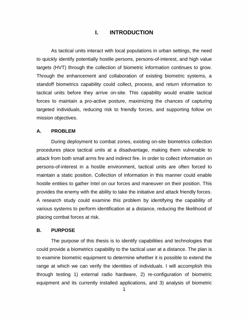
I. INTRODUCTION
As tactical units interact with local populations in urban settings, the need
to quickly identify potentially hostile persons, persons-of-interest, and high value
targets (HVT) through the collection of biometric information continues to grow.
Through the enhancement and collaboration of existing biometric systems, a
standoff biometrics capability could collect, process, and return information to
tactical units before they arrive on-site. This capability would enable tactical
forces to maintain a pro-active posture, maximizing the chances of capturing
targeted individuals, reducing risk to friendly forces, and supporting follow on
mission objectives.
A. PROBLEM
During deployment to combat zones, existing on-site biometrics collection
procedures place tactical units at a disadvantage, making them vulnerable to
attack from both small arms fire and indirect fire. In order to collect information on
persons-of-interest in a hostile environment, tactical units are often forced to
maintain a static position. Collection of information in this manner could enable
hostile entities to gather Intel on our forces and maneuver on their position. This
provides the enemy with the ability to take the initiative and attack friendly forces.
A research study could examine this problem by identifying the capability of
various systems to perform identification at a distance, reducing the likelihood of
placing combat forces at risk.
B. PURPOSE
The purpose of this thesis is to identify capabilities and technologies that
could provide a biometrics capability to the tactical user at a distance. The plan is
to examine biometric equipment to determine whether it is possible to extend the
range at which we can verify the identities of individuals. I will accomplish this
through testing 1) external radio hardware, 2) re-configuration of biometric
equipment and its currently installed applications, and 3) analysis of biometric
2
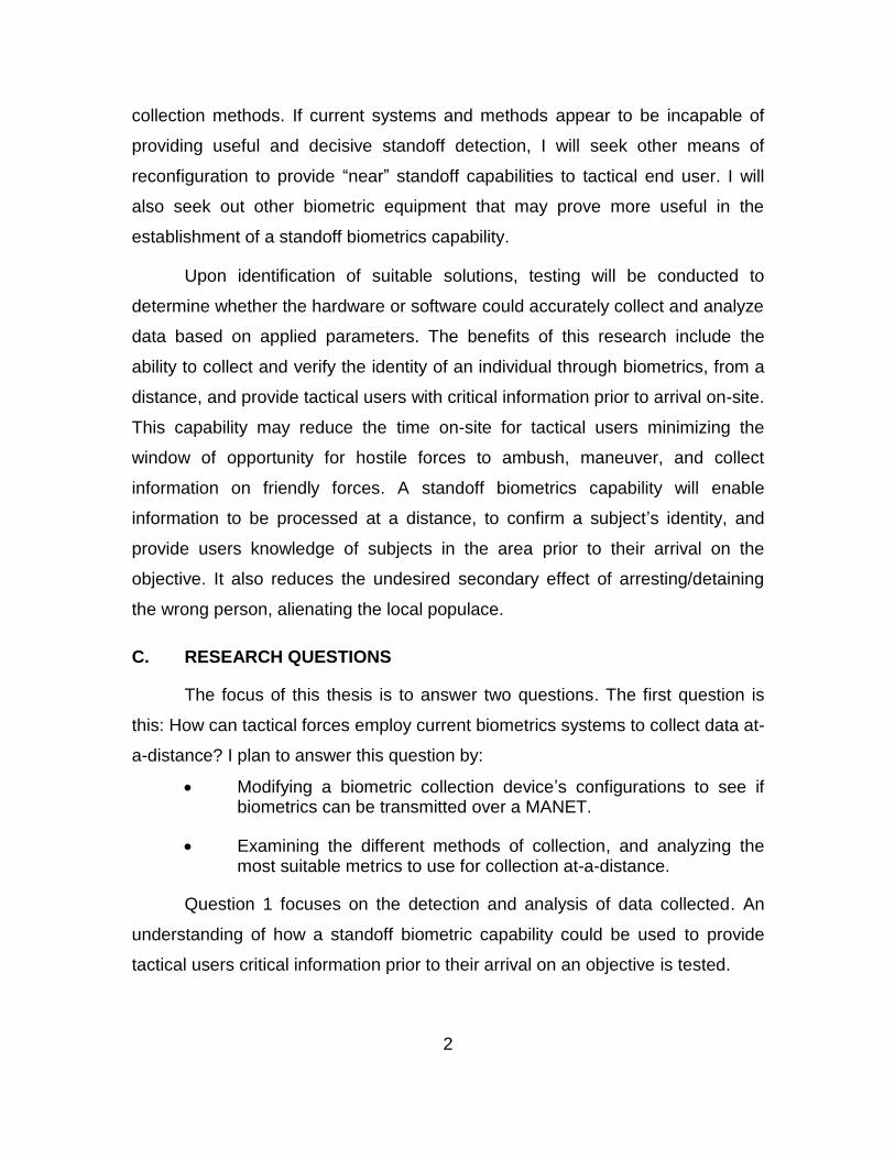
collection methods. If current systems and methods appear to be incapable of
providing useful and decisive standoff detection, I will seek other means of
reconfiguration to provide “near” standoff capabilities to tactical end user. I will
also seek out other biometric equipment that may prove more useful in the
establishment of a standoff biometrics capability.
Upon identification of suitable solutions, testing will be conducted to
determine whether the hardware or software could accurately collect and analyze
data based on applied parameters. The benefits of this research include the
ability to collect and verify the identity of an individual through biometrics, from a
distance, and provide tactical users with critical information prior to arrival on-site.
This capability may reduce the time on-site for tactical users minimizing the
window of opportunity for hostile forces to ambush, maneuver, and collect
information on friendly forces. A standoff biometrics capability will enable
information to be processed at a distance, to confirm a subject’s identity, and
provide users knowledge of subjects in the area prior to their arrival on the
objective. It also reduces the undesired secondary effect of arresting/detaining
the wrong person, alienating the local populace.
C. RESEARCH QUESTIONS
The focus of this thesis is to answer two questions. The first question is
this: How can tactical forces employ current biometrics systems to collect data at-
a-distance? I plan to answer this question by:
Modifying a biometric collection device’s configurations to see if biometrics can be transmitted over a MANET.
Examining the different methods of collection, and analyzing the most suitable metrics to use for collection at-a-distance.
Question 1 focuses on the detection and analysis of data collected. An
understanding of how a standoff biometric capability could be used to provide
tactical users critical information prior to their arrival on an objective is tested.

3
The second research question is this: How can biometric sensor output be
used to enhance biometric awareness in a hostile environment?
Question 2 calls to identify a method and platform available for biometrics
systems, to provide a real-time, multi-visual, standoff capability for tactical users.
An understanding of current and evolving concepts and how they might affect the
way we conduct biometric collection is discussed. Finally, I analyze the
advantages and disadvantages of implementing new concepts and how they
would affect the tactical user.
D. SIGNIFICANCE
The experimentation and findings are significant to counterterrorism
operations, combat operations, and future operations because they provide
insight into the possibility of enhancing existing capabilities, while enhancing the
user’s ability to detect, identify, and apprehend individuals before they are able to
act.
The ability to collect biometrics at-a-distance would provide tactical users
with critical information on subjects without the need for their cooperation, and,
minimizing to contact with local populations. This capability may reduce the time
on-site for tactical forces, minimizing the window of opportunity for hostile forces
to ambush, maneuver, or collect intelligence on friendly forces. A standoff
biometrics capability could ensure collected information is processed at lower risk
and, in near-real time so that confirmation of a suspect’s identity can be sent to
the user, prior to contact with the individual.
A limiting factor will be the availability of bandwidth to support biometrics
information transmission and reception. The development or integration of
software applications capable of collecting data at-a-distance will be expensive
and require testing in austere environments. Providing standoff detection may
require modifications to hardware and software currently in use. Security
protocols may need to be re-configured to allow flow of data wirelessly.
4
These factors could be mitigated by the use of handheld radios employed
as nodes in a MANET to allow data flow on the move. For instances where the
use of such devices may not permit transmission of data outside the configured
protocols, modifications could be made to allow data transfer.
E. METHODOLOGY
Experimentation is used to answer my research questions. I organized my
experiments in such a way that most readers, without knowledge of biometrics,
could understand each finding. Each experiment is discussed and my
observations are applied to future concepts of research and experimentation. I
will describe the equipment setup and the processes I use to develop my
conclusions.
F. ORGANIZATION
The remainder of this thesis is organized as follows. Each chapter covers
a specific topic that will build onto the next chapter.
Chapter II presents the review of the literature. It covers some of the basic
biometric collection methods such as fingerprinting, facial recognition, iris
scanning, and gait. I discuss each section in some detail and provide the current
techniques in use today, as well as some innovative methods and techniques
being examined to improve collection of that metric.
Chapter III covers the methodology used in the thesis. In this chapter, I
define “standoff biometrics/at-a-distance” in the context in which I think it would
be conducted and any shifts in perception that may take place throughout the
thesis. I describe systematic, the processes and procedures used during setup
and experimentation in order to provide my perspective. I briefly discuss each
experiment, what I did or did not achieve, and how I used it to prepare for the
next experiment.
Chapter IV focused on data analysis. I discuss the data collected, and its
significance. Based on the knowledge developed through my literature review,

5
experimentation, and other sources, I interpret the meaning of my results and
discuss how any personal bias influenced my decisions during experimentation.
Chapter V provides my conclusion. In this chapter, I summarize the thesis
and the highlights of the research conducted. I talk about any limitations of my
research, the implications of my findings, conclusions based on the facts, issues
encountered, and finally my interpretation. I also offer recommendations for
further research and possible ideas to be pursued.

6
THIS PAGE INTENTIONALLY LEFT BLANK

7
II. LITERATURE REVIEW
This literature review provides information on how biometric recognition is
done and the standard practice of biometric collection. I distinguish the difference
between verification and identification, and, what is meant by contact,
contactless, and at-a-distance biometrics.
The different categories that biometric collection methods comprise are
described and the benefits and limitations of each type are discussed. The types
of biometric methods are listed and the way they are employed is described in
sub-sections of the literature review.
Overall, this literature review defines multiple biometric concepts in order
to ensure the reader has sufficient knowledge and understanding of biometric
techniques and procedures. This baseline of knowledge will help the reader
understand the perspectives, findings, and actions taken during experimentation.
A. THE HISTORY OF BIOMETRICS
Biometric identification may be a new concept to the average person but
in fact, we have been using biometric recognition for thousands of years.
Evidence for the use of biometrics can be found as early as the prehistorical age
from authors and artists who left behind pictures and fingerprint impressions as
their signatures (Griaule Biometrics, 2014). Evidence suggests the Babylonians
used fingerprinting as early as 500 B.C. for business transactions on tablets
(Griaule Biometrics, 2014). Out of all the biometric techniques, facial recognition
is the oldest and most fundamental technique of them all (Mayhew, 2015). We
use facial recognition in our lives every day and it is something we continue to
develop as we interact with other members of society.
Human behavioral characteristics such as speech and gait recognition are
other ways in which individuals recognize others in society (Griaule Biometrics,
2014). These characteristics are used to identify with people, unconsciously,
every day (Griaule Biometrics, 2014).
8
Griaule Biometrics (2014) describes that Joâo de Barros was the first to
report the use of biometrics. He was a Portuguese explorer in the 14th century
who had traveled the world. Barros described how Chinese merchants used
biometric techniques such as palm and foot printing to identify one child from
another. He states that as our understanding of biometrics evolved, it was only a
matter of time before a biometric system was developed to wield this capability
(Griaule Biometrics, 2014).
In 1858, a man by the name of Sir William Herschel developed the first
system to document hand imagery for identification purposes (Mayhew, 2015).
He used hand print imagery on contracts to distinguish each employee so that
when payday came, he could identify whom his employees were (Mayhew,
2015).
Griaule Biometrics (2014) tells us that an anthropologist by the name of
Alphonse Bertillon contributed to biometric collection by establishing a biometric
field of study. Bertillon used a system known as the Bertillonage system, which
recorded basic body measurements, the physical description of an individual,
and, used photographs to capture multiple characteristics, which led to the
advancement of criminal and personnel identification (Griaule Biometrics, 2014).
Later findings revealed that these measurements were not unique and therefore
would lead to inaccuracy and failure of the system (Griaule Biometrics, 2014).
Griaule Biometrics (2014) explains how the first classification methods for
fingerprints were developed and the effect it had on criminal identification. In
1892, Sir Francis Galton established the technique of using the minutiae points of
a print to establish the process of fingerprinting still used today. In 1896, the
Bertillon system was replaced due to advancements in biometric collection. Sir
Edward Henry, General Inspector of the Bengal police began using Galton’s
processes for identification of criminals. The inspector’s establishment of a filing
system was a precursor to the biometric databases and watch lists we use today
(Griaule Biometrics, 2014).
In 1936, an ophthalmologist by the name of Frank Burch, proposed the
concept of iris recognition to enhance biometric identification and verification
9
capabilities (Mayhew, 2015). In 1985, Leonard Flom and Alan Safir presented
evidence that every iris was unique (Mayhew, 2015). This opened the door for
the use of iris scans as a means of identification. The following year a patent was
issued which allowed the use of the iris for identification (Mayhew, 2015).
Facial recognition technology begins to take off in the 1980s with the use
of a semi-automated facial recognition system and the capability to conduct real
time facial recognition (Mayhew, 2015). There were many agencies such as
DARPA, that were encouraged to develop facial recognition systems, algorithms,
and supporting technology (Mayhew, 2015).
There were many challenges to the advancement of fingerprinting
techniques. During the 1994 Integrated Automated Fingerprint Identification
System (IAFIS) competition, many of these challenges were looked at and a list
of the top three was devised:
1. Process of digital fingerprinting,
2. The process of recording ridge characteristics of a print, and
3. How to apply the print accurately to an individual once the print has been recorded. (Mayhew, 2015)
This event led to the operational deployment of IAFIS in 1999, which
continues to be used to this day.
National Science and Technology Council (NSTC) (2009) explains that in
2004, the DOD looked to mitigate and track potential national security threats to
the U.S. As a result, the Automated Biometric Identification System (ABIS) was
implemented to provide the government the capability to monitor personnel that
may present a national security threat. This system has the ability to collect rolled
fingerprints, photographs from varies angles, voice, iris, and oral DNA (Mayhew,
2015). The multimodal systems we use today, the SEEK and BATES/HIIDES,
utilize many of these methods for biometric collection on persons of interest.
The evolution of biometric methods and technologies has had a profound
impact on how we approach identification in modern times. With the development
10
of autonomous systems capable of multiple biometric collection methods,
identification of individuals up close and afar will provide better security and
access control then previous experiences.
B. STANDARD PRACTICES OF BIOMETRIC RECOGNITION
Biometric recognition processes compare inquiries collected from the input
device against data already enrolled in a database (Tistarelli, Li, & Chellappa,
2009). There are two modes used for comparison of collected data: verification
and identification (Tistarelli et al., 2009).
Verification is a 1:1 relationship in which facial data is compared against
the existing data of an individual to verify they are whom they say they are (e.g.,
electronic passport) (Tistarelli et al., 2009). The verification mode is less
intensive for computer systems because the database does not compare data
against all of the data collected as it would during the identification process
(Diefenderfer, 2006)
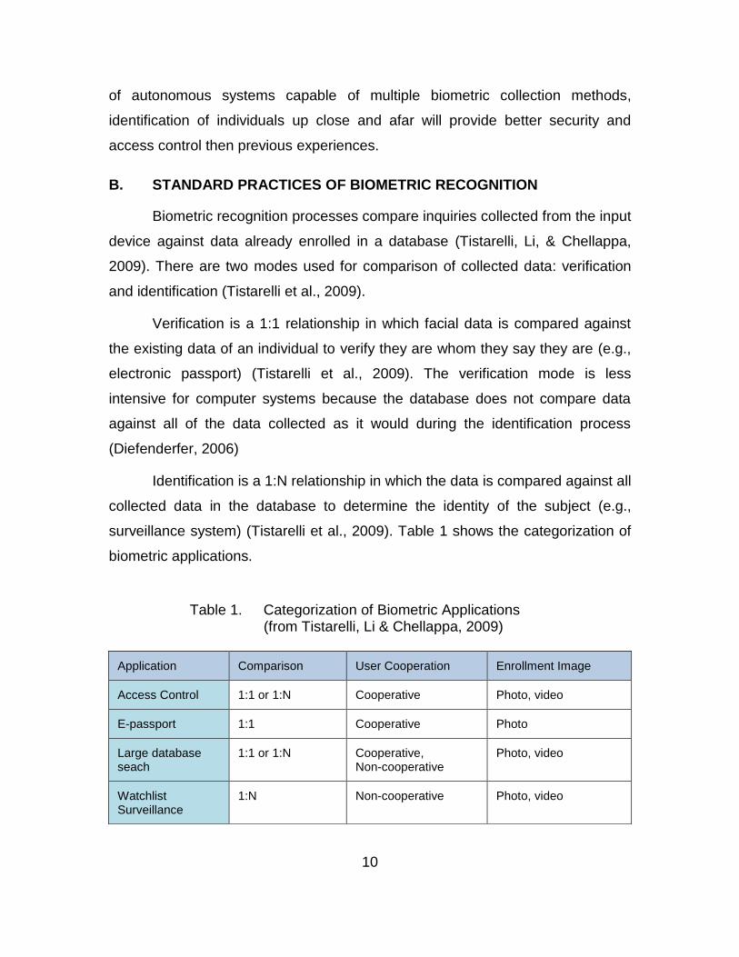
Identification is a 1:N relationship in which the data is compared against all
collected data in the database to determine the identity of the subject (e.g.,
surveillance system) (Tistarelli et al., 2009). Table 1 shows the categorization of
biometric applications.
Table 1. Categorization of Biometric Applications (from Tistarelli, Li & Chellappa, 2009)
Application Comparison User Cooperation Enrollment Image
Access Control 1:1 or 1:N Cooperative Photo, video
E-passport 1:1 Cooperative Photo
Large database seach
1:1 or 1:N Cooperative, Non-cooperative
Photo, video
Watchlist Surveillance
1:N Non-cooperative Photo, video

11
1. Modalities of Biometric Collection
Tistarelli et al., (2009) states contact, contactless, and at-a-distance are
the three common modalities used for biometrics collection. He explains that
these categories divide collection dependent on the distance, where contact
requires physical interaction with equipment (Tistarelli et al., 2009). Contactless
collection takes place from two centimeters to one meter from the equipment,
requiring some degree of cooperation on the part of the subject. At-a-distance
biometric collection is any collection beyond one meter and is focused on an
individual’s gait and other attributes that require no cooperation from the
individual (Tistarelli et al., 2009). At-a-distance biometrics is also known as
remote biometrics and standoff biometrics, depending on the author.
Diefenderfer (2006) tells us how contact modalities such as fingerprinting
require the cooperation of the individual. Fingerprinting is best utilized for
verification systems rather than identification systems because of the resources
needed to receive a match. A basic biometric systems used for data collection
relies on hand geometry (Diefenderfer, 2006). Both two-dimensional and three-
dimensional collection systems provide adequate data but the three dimensional
system provides more information and has greater reliability (Diefenderfer, 2006).
Contactless modalities such as touchless fingerprint sensors, iris
scanning, and some facial recognition tools require some cooperation from the
subject (Tistarelli et al., 2009). Contactless modalities are less invasive and are
usually more acceptable for public use because they avoid the issues of hygiene
and physiological resistance that users may have with touching the same sensor
(Fujitsu, 2013).
At-a-distance or remote biometric modalities such as facial recognition,
gait, and some newer iris scanning systems provide the user with identification
capabilities without the individual’s knowledge or the need for their cooperation.
Remote biometrics is a non-invasive technique enabling the user to collect

12
information and identifies subjects prior to contact. The increased distance of
biometric identification presents some sensory and false acceptancy rate errors.
The use of multiple types of sensors can complicate the process of
collecting details of a face or fingerprint. For instance, light levels affect the ability
of the sensor to collect accurate imagery (Pato & Millet, 2010). When conducting
standoff biometrics, the activities that take place between the sensor and item
being scanned could distort or prevent the acquisition of accurate data. To
counter this challenge, multiple algorithms for segmentation of low and high
quality resolution fingerprints could provide a tool to collect accurate data on a
subject given environmental or hardware restraints (Pato & Millet, 2010). These
issues degrade biometric system capabilities when conducted in a normal
capacity, that is, when the person being scanned, is in physical contact with
biometric equipment. A biometric system attempting the same techniques at-a-
distance will have to manage these issues as well as equipment and application
limitations.
C. BIOMETRIC CHARACTERISTICS
The use of uniquely identifying characteristics provides an efficient way for
organizations to identify personnel, limit access to information, and control
access to areas of interest. Biometric characteristics such as a person’s
fingerprints, face, iris pattern, gait, and thermal footprint are unique for each
person. These characteristics are normally captured up close, within a few feet,
and with the consent and cooperation of the individual.
There are two categories of biometrics used to identify or verify
individuals’ identities. Biometric characteristics are either physiological or
behavioral. Each category will be discussed and the differences between them
will be provided below.
13
1. Physiological
Physiological biometrics is based upon the recognition of physical
characteristics, such as fingerprints, facial recognition, iris recognition, DNA, ear,
and hand geometry (Verett, 2006). Measurement of these characteristics may
necessitate invasive techniques requiring cooperation from the individual being
collected on. Many of these characteristics are collected using contact and
contactless modalities. Further advances in biometric technology have enabled
the collection of these characteristics at a distance. For the purposes of this
thesis, only the fingerprint, facial, and iris recognition methods will be covered.
a. Fingerprinting
Fingerprinting is a common method of biometric identification and
verification. Features called minutiae, forks, and endings are used to identify
unique differences in an individual’s fingerprints (Verett, 2006). The type,
orientation, spatial frequency, curvature, and position of fingerprint features are
measured to distinguish the fingerprints of one person, from another (Defense
Forensics and Biometrics Agency [DFBA], 2014).
Verett (2006) describes the three different fingerprint patterns used to
distinguish fingerprints, which are the loop, the whorl, and the arch. The loop
pattern has ridges enter from either side and then exit the same way. A whorl
pattern is more circular in construct where the arch pattern looks more like a hill
with ridges entering from one side, moving across the finger while rising, then
falling and exiting the opposite side.
The advantage of using fingerprinting is that it is a proven method of
identification and culturally, it is accepted as a means of identification (Verett,
2006). A disadvantage is that fingerprinting is an invasive collection method
requiring the cooperation of the individual. The individual is also aware that his
biometrics are being recorded for identification. This is important if an individual
is having fingerprints taken to compare against latent prints related to a crime. If
the subject has not been charged in a crime, this could provide them time to flee.
14
Fingerprints are used for many applications in our lives. Government
agencies, banking, medical and insurance industries, information security, and
access control systems use fingerprinting technology to identify and verify
individuals (Verett, 2006). As technology continues to evolve, fingerprints will
become more reliable and result in fewer misidentifications.
b. Facial Recognition
Facial recognition tools provide end users with a variety of options when
collecting biometric information on a subject, each with potential advantages and
disadvantages.
There are many ways to approach collection of facial information as well.
The creation of facial recognition images can be done through the construction of
mosaicked panoramic images which consist of pieces of 2-D pictures put
together to get a full 3-D facial image (Yang et al., 2005). The complexity of
biometric identification is reduced by using multiple cameras followed by fast
linear transformations of the images (Yang et al., 2005). Real-time applications
can benefit from this due to the low amount of processing required to create an
image (Yang et al., 2005).
Principal-component analysis (PCA) is an adaptable approach to facial
recognition that provides the user flexibility when dealing with an image of poor
quality (Yang et al., 2005). It uses statistical procedure to correlate variables into
sets of linearly uncorrelated variables called principal components (Wikipedia,
2015). PCA is the idea of facial recognition using small set of features based on
approximates to develop an image (Yang et al., 2005).
Spatial and frequency representation were two panoramic facial
representations methods used to conduct mosaic biometric identification.
Frequency representation gave a better correct facial recognition rate of 97.46%
opposed to the spatial representation rate of 93.21% (Yang et al., 2005). The
advantage of frequency representation is the reduction of data volume to be
15
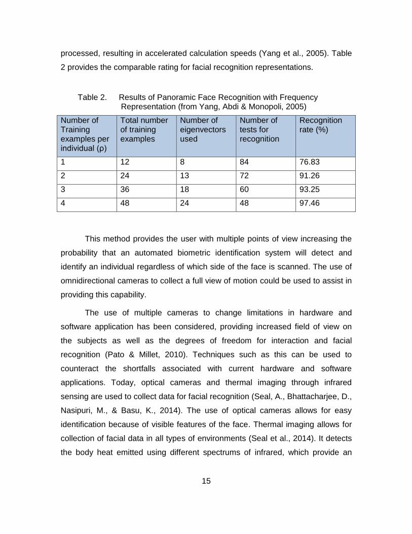
processed, resulting in accelerated calculation speeds (Yang et al., 2005). Table
2 provides the comparable rating for facial recognition representations.
Table 2. Results of Panoramic Face Recognition with Frequency Representation (from Yang, Abdi & Monopoli, 2005)
Number of Training examples per individual (ρ)
Total number of training examples
Number of eigenvectors used
Number of tests for recognition
Recognition rate (%)
1 12 8 84 76.83
2 24 13 72 91.26
3 36 18 60 93.25
4 48 24 48 97.46
This method provides the user with multiple points of view increasing the
probability that an automated biometric identification system will detect and
identify an individual regardless of which side of the face is scanned. The use of
omnidirectional cameras to collect a full view of motion could be used to assist in
providing this capability.
The use of multiple cameras to change limitations in hardware and
software application has been considered, providing increased field of view on
the subjects as well as the degrees of freedom for interaction and facial
recognition (Pato & Millet, 2010). Techniques such as this can be used to
counteract the shortfalls associated with current hardware and software
applications. Today, optical cameras and thermal imaging through infrared
sensing are used to collect data for facial recognition (Seal, A., Bhattacharjee, D.,
Nasipuri, M., & Basu, K., 2014). The use of optical cameras allows for easy
identification because of visible features of the face. Thermal imaging allows for
collection of facial data in all types of environments (Seal et al., 2014). It detects
the body heat emitted using different spectrums of infrared, which provide an
16
efficient way of collecting facial data. The environment provides less interference
when using thermal scanning to collect facial data.
The availability of unmanned aerial vehicles (UAV) with high-resolution
camera equipment will be an issue for at-a-distance collection of imagery and
data (McKeehan, 2008). Identification of interest points and the resolution of
pictures and video is a difficult process that will need to be addressed
(McKeehan, 2008). Biometrics systems are inherently problematic, and they
need to be assessed within the context of fundamental and critical characteristics
such as variation within a person, the sensors, feature extraction and data
algorithms, and data integrity (Pato & Millet, 2010). The ability to define what
“variation within a person” is and develop algorithms to extract such patterns
provides a serious gap in efficient biometrics collection. This gap will magnify as
the attempt to collect biometrics at a distance is compounded by resolution
limitations, bandwidth, and software and hardware restrictions.
c. Iris Scanning
The iris is an annular region between the black pupil and the white sclera
(Wang, Tan & Jain, 2003). The texture, connective tissues, rings, and colorations
of the iris are among the four hundred characteristics that provide a unique
quality enabling an individual to be identified (Verett, 2006). These characteristics
make iris recognition more reliable then fingerprinting (Verett 2006).
Some advantages to the use of the iris as a way to identify a subject are
that it is contactless and a little less invasive than fingerprinting. The risk of
impersonation is very low because modification to the iris would cause damage
to the individual’s ability to see (Verett, 2006). A disadvantage to iris scanning is
that it requires the cooperation of the individual and both the user and operator
need to have an understanding of how to use iris scanners in order to get
accurate results (Verett, 2006). Iris scanning is currently used to identify
individuals for bank transactions, access control, and motor vehicle registrations
just to name a few.
17
2. Behavioral
Behavioral biometrics can be described as traits that are learned or
acquired over time such as voice, signature, keystroke recognition, and gait
(Verett, 2006). Behavioral biometrics focus on the patterns of movement or the
way we act. For the purposes of this thesis, only gait and voice biometric
methods will be discussed.
a. Gait
Gait is the way in which an individual walks. Each person has a specific
pattern in which he moves about an area. The posture and the way someone
steps provide a pattern specific to that individual that can be used to identify him
at-a-distance. A person’s gait is learned and is a result of acquired patterns of
motion based on specific body motions and their relationship with each other.
An advantage of using gait recognition is that it is useful in identifying
subjects at-a-distance. This is very useful in situations where contact and
contactless methods are not available for identification or there is a need to
remain covert. Identification at-a-distance using gait provides the user with
identification of the individual without the need to be on-site and in a potentially
hazardous environment. An ideal situation would be to identify an individual to
see if he is an HVT and once that is done, the user could than take action with a
high probability that the individual is who they think he is. An example of this
could be the identification of Osama Bin Laden based on his gait and other
behavioral features.
Some disadvantages are that gait is not as reliable as physiological
characteristics and that a person’s gait could be modified either through injury or
on purpose. Another disadvantage is that the individual needs to be walking in
order to obtain an accurate reading. If the person of interest is stationary, either
standing still or sitting, the ability to measure a person’s gait accurately will not be
possible. Although gait measurement does not need the “cooperation” of the
individual in the way we require it for contact type methods such as fingerprinting
18
and iris scanning, the individual does need to cooperate in the sense that he is
moving.
b. Voice
Voice or speech identification analysis studies the sounds, phonetics, and
vocals generated by a person using the mouth, nasal cavities, vocal tract and its
effect on the way the voice is projected (Verett, 2006). Voice templates must be
produced to establish baseline measurement and comparison standards for
voice identification. This requires a person to speak and repeat several phrases
in order to collect all possible characteristics specific to that individual (Verett,
2006).
Some disadvantageous are that microphones or listening devices must be
close enough to the target to detect and identify the individual. Interference from
other subjects and the environment can be a problem when trying to analyze and
identify a specific subject. Voice recognition systems use several variables or
parameters in the recognition of a voice/speech pattern to include the pitch,
dynamics, and waveform (Verett, 2006).
D. BIOMETRIC COLLECTION SYSTEMS
1. SEEK
There are many biometric systems used for collection of biometric data on
subjects. The SEEK is one of the systems used in military applications today.
This system is a handheld, portable device, which provides users with the
capability to collect and process biometrics in various adverse environments.
Although the SEEK provides an identification capability, a match/no match
response from the ABIS in near-real time is currently non-existent.
Near-real time communication between the SEEK and ABIS provides
forces with the capability to collect information, send it off for analysis, and
receive a processed response within a timely manner. A timely response enables
forces in an area of operation to act on biometric collection results immediately
19
without the need to revisit an area to locate an individual. Near-real time
match/no match criteria enables forces to act in their current situation with
relevant information in order to apprehend subjects identified as HVTs or
persons-of-interest on the spot, rather than releasing them and returning to the
nearest FOB for data analysis.
The Secure Electronic Enrollment Kit, or SEEK, is a multimodal biometric
collection system built to perform in austere environments. It has 3G/4G wireless
connectivity and the capability to maintain a 250,000 record watch list,
eliminating the need to transport unknown subjects in uncertain conditions for
enrollment or identification; further reducing operational risk (Crossmatch, 2014).
Crossmatch (2014) states the SEEK has a Machine Readable Zone (MRZ) which
designates an area for data to be encoded. It also contains a Radio-Frequency
Identification (RFID) readers and the capability to verify electronic passports and
other non-contact credentials. It is interoperable with several software
development kits and capable of using many types of software to include MOBS,
MARS, FAST middleware, and IDTrak matching applications as well as
communication with IAFIS and ABIS databases (Crossmatch, 2014).
The ABIS database supported Operations Enduring and Iraqi Freedom by
providing a central, authoritative, repository for biometrics records (Kiefer &
Trissell, 2010).
2. 3D Wireless Binocular Face Recognition System
Conducting biometric collect on a non-cooperative subject without their
knowledge, at-a-distance, and, analyzing the data in near-real time, is almost
non-existent. In response to this capability gap, Stereo Vision Imaging Inc. (SVI)
and the Space and Naval Warfare System Command Center
(SPAWARSYSCEN) have teamed up to develop a wireless binocular facial
recognition system capable of meeting a need for covert, at-a-distance, biometric
data collection and analysis.
20
This device is designed to meet the United States Special Operations
Command (USSOCOM) biometric sensitive site exploitation (SSE) operational
requirements (SVI & SPAWARSYSCEN, 2014b). The 3D wireless binocular
system provides an extended biometric recognition capability at-a-distance for
identification and verification of non-cooperative subjects enabling discreet
removal of threats (Schulz, 2015). The binocular device can be used wirelessly
or can be hard wired based on available infrastructure and supporting capabilities
(Schulz, 2015). The basic characteristics are simple in design; based off a set of
binoculars and video and imaging capabilities put together into one device.
The 3D wireless facial recognition system comes with a laptop containing
software for analysis. The binocular system can be used two ways: on a tripod or
freehand. Freehand use may require some modifications to parameters listed in
a menu called ‘pipeline’. This menu contains the parameters necessary to
calculate for atmospheric issues, 3D segmentation, photometric normalization,
and image resolution enhancement. When using the device in a handheld
capacity, the ability to maintain a steady picture of the subject being scanned will
result in difficulty with collection and analysis. This menu helps to compensate for
fluctuations from environmental elements to include the movement of a person’s
hand when holding the device.
3. Experimental Capabilities
The use of IR and optical camera applications combined with the ability to
combine both low and high-resolution imagery may prove to be an effective
standoff biometrics capability. Cameras that can zoom in and identify data in fine
detail could be run against a modified biometrics algorithm software package
enabling tactical forces to acquire information on persons-of-interest at a
distance based off facial recognition, gait, fingerprints, and iris scans. Through
the combination of the most relevant biometric techniques, equipment, and
software, a standoff biometric capability could enable tactical forces to utilize
UAVs to conduct biometric scans of individuals at a distance.
21
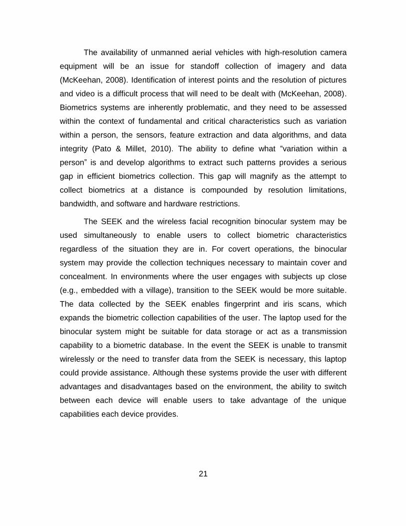
The availability of unmanned aerial vehicles with high-resolution camera
equipment will be an issue for standoff collection of imagery and data
(McKeehan, 2008). Identification of interest points and the resolution of pictures
and video is a difficult process that will need to be dealt with (McKeehan, 2008).
Biometrics systems are inherently problematic, and they need to be assessed
within the context of fundamental and critical characteristics such as variation
within a person, the sensors, feature extraction and data algorithms, and data
integrity (Pato & Millet, 2010). The ability to define what “variation within a
person” is and develop algorithms to extract such patterns provides a serious
gap in efficient biometrics collection. This gap will magnify as the attempt to
collect biometrics at a distance is compounded by resolution limitations,
bandwidth, and software and hardware restrictions.
The SEEK and the wireless facial recognition binocular system may be
used simultaneously to enable users to collect biometric characteristics
regardless of the situation they are in. For covert operations, the binocular
system may provide the collection techniques necessary to maintain cover and
concealment. In environments where the user engages with subjects up close
(e.g., embedded with a village), transition to the SEEK would be more suitable.
The data collected by the SEEK enables fingerprint and iris scans, which
expands the biometric collection capabilities of the user. The laptop used for the
binocular system might be suitable for data storage or act as a transmission
capability to a biometric database. In the event the SEEK is unable to transmit
wirelessly or the need to transfer data from the SEEK is necessary, this laptop
could provide assistance. Although these systems provide the user with different
advantages and disadvantages based on the environment, the ability to switch
between each device will enable users to take advantage of the unique
capabilities each device provides.
22
E. CONSIDERATIONS
Biometric collection raises some questions on whether or not the process
of collecting biometrics on an individual is a violation of privacy. Many people see
the collection of biometrics as a tool used to identify “dead beats” and solve
crimes (Black, 2008). This perception is the reason why many people are
reluctant to provide biometric data or submit to collection methods request by
organizations. The following documentation will provide information on legislation
enacted which defines collection criteria in order to protect the unlawful
acquisition of biometric characteristics.
1. U.S. Constitution and Types of Privacy
The U.S. Constitution does not directly address privacy but there are
provisions that address privacy protections (NSTC et al., 2006). These provisions
include topics relevant to the following:
The First Amendment
The Third Amendment
The Fourth Amendment
Fifth Amendment (NSTC et al., 2006).
In 1965, the U.S. Supreme Court stated there was a constitutional right to
privacy, which spawns from these individual rights (NSTC et al., 2006). These
“zones” address situations that could arise with the use of biometric data, such
as the unreasonable search and seizure due to the collection of personal
property such as fingerprints, iris scans, without due cause (NSTC et al., 2006).
Biometric collection must be done within the confines of the laws, which are
fundamental to our society and should guide the way collection is done (NSTC et
al., 2006).
A clear definition of “the right to privacy” must be defined so people can
understand what rights an individual has. Horton III (2009) states there are five
spheres of individual autonomy:

23
1. Associational or group interactive privacy,
2. Data or information privacy,
3. Physical or personal privacy,
4. Judgment or decisional privacy, and
5. Communications privacy (Horton III, 2009).
The spheres most likely targeted for biometric collection are information,
physical, and associational privacies. (Horton III, 2009).
Horton III (2009) explains what defines these three spheres of privacy.
Associational privacy covers the establishment of friendships such as political
and business pursuits, and recreation activities. The Supreme Court’s
interpretation of associational privacy is the protection of individuals against
undue intrusion by the government. Informational privacy deals with information
about ones person such as medical records. Physical privacy is the control over
ones physical attributes such as fingerprints, blood, and access to body parts
(Horton III, 2009).
The U.S. Constitution lays the foundation for the rules and regulations
established by Congress for the protection of personal property. Public laws
attempt to clarify the Constitution and the rights defined to protect the individual
by providing in-depth detail in specific circumstances. When issues arise that are
not clearly addressed by the Constitution, case law is applied and stands as the
ruling for each specific issue (Black, 2008).
2. Freedom of Information Act
The Freedom of Information Act (FOIA) was the first attempt to establish
lateral limits on the disclosure of information (American Health Information
Management Association [AHIMA], 2010). In 1966, President Johnson signed the
FOIA that established guidelines for the disclosure of limited and non-critical
information controlled by the U.S. government (AHIMA, 2010). The following list
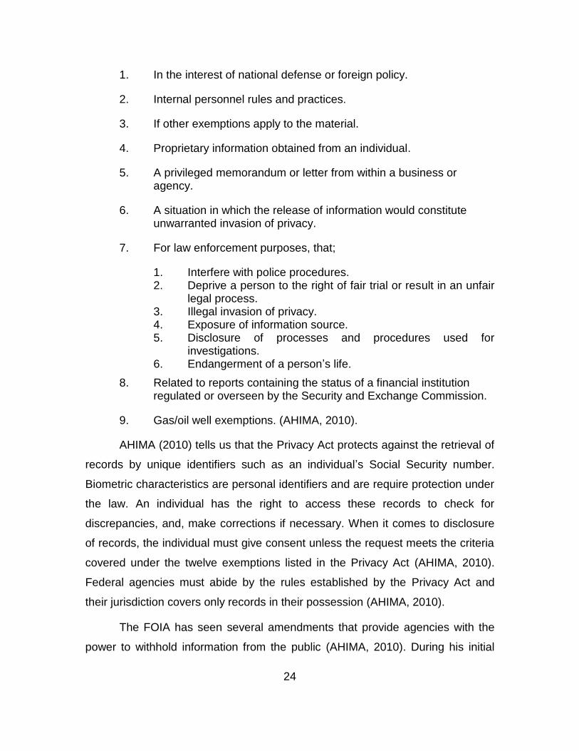
addresses exemptions to disclosure.
24
1. In the interest of national defense or foreign policy.
2. Internal personnel rules and practices.
3. If other exemptions apply to the material.
4. Proprietary information obtained from an individual.
5. A privileged memorandum or letter from within a business or agency.
6. A situation in which the release of information would constitute unwarranted invasion of privacy.
7. For law enforcement purposes, that;
1. Interfere with police procedures. 2. Deprive a person to the right of fair trial or result in an unfair
legal process. 3. Illegal invasion of privacy. 4. Exposure of information source. 5. Disclosure of processes and procedures used for
investigations. 6. Endangerment of a person’s life.
8. Related to reports containing the status of a financial institution regulated or overseen by the Security and Exchange Commission.
9. Gas/oil well exemptions. (AHIMA, 2010).
AHIMA (2010) tells us that the Privacy Act protects against the retrieval of
records by unique identifiers such as an individual’s Social Security number.
Biometric characteristics are personal identifiers and are require protection under
the law. An individual has the right to access these records to check for
discrepancies, and, make corrections if necessary. When it comes to disclosure
of records, the individual must give consent unless the request meets the criteria
covered under the twelve exemptions listed in the Privacy Act (AHIMA, 2010).
Federal agencies must abide by the rules established by the Privacy Act and
their jurisdiction covers only records in their possession (AHIMA, 2010).
The FOIA has seen several amendments that provide agencies with the
power to withhold information from the public (AHIMA, 2010). During his initial

25
years as president and in an effort to promote transparency within the
government, President Barack Obama revoked restrictions placed on
government records (AHIMA, 2010).
3. Privacy Act of 1974
The Privacy Act of 1974 addresses the access of information stored in
databases, and protection necessary for the government to minimize privacy
violations (Horton III, 2009). It governs how federal officials handle personal
information and the protocols put in place to mitigate unlawful handling of an
individual’s personal information (Black, 2008).
The Privacy Act does not clearly define the biometric methods used for the
acquisition and storage of data, however it does reference the way in which
personal records are to be handled (Black, 2008). The accuracy of data collected
and its storage in personal records raises some concerns because every citizen
has the right to review and correct errors, however, the ability to identify errors in
biometrically collected data is very hard (Black, 2008).
An argument can be made that the Privacy Act of 1974 does address
biometric collection because biometric characteristics are personal attributes of
an individual. The Privacy Act specifies that collection of biometric information is
warranted only for law enforcement activities, by legislative authority, or the
individual collected on (Horton III, 2009). Once the government engages in
activities that encroach on the five spheres of autonomy, an individual’s rights
must be taken into consideration, and a decision must be made to determine
whether the risk to the government being subjected to violations of privacy
legislation is worth the possible outcome of acquiring biometric data (Horton III,
2009).
Horton III (2009) states a major focus of the Privacy act is to provide
guidelines on the use of personal information. The following bullets provide the
essential elements of implementing an effective privacy policy, are used to
26
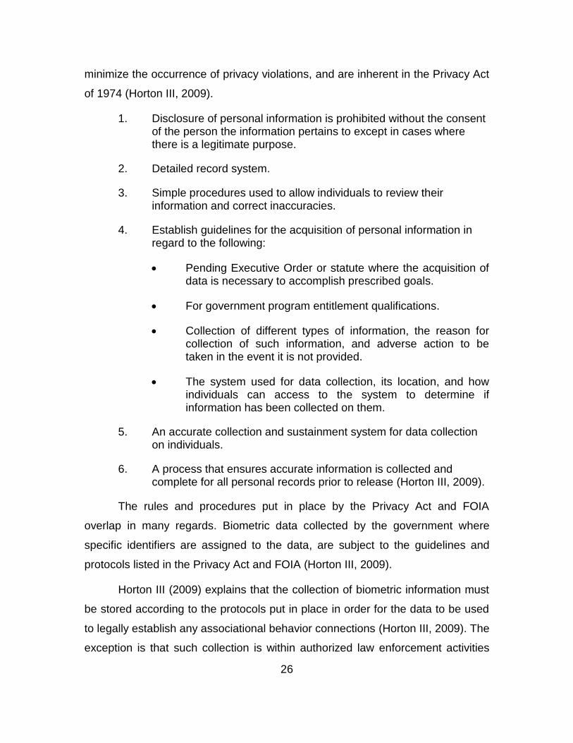
minimize the occurrence of privacy violations, and are inherent in the Privacy Act
of 1974 (Horton III, 2009).
1. Disclosure of personal information is prohibited without the consent of the person the information pertains to except in cases where there is a legitimate purpose.
2. Detailed record system.
3. Simple procedures used to allow individuals to review their information and correct inaccuracies.
4. Establish guidelines for the acquisition of personal information in regard to the following:
Pending Executive Order or statute where the acquisition of data is necessary to accomplish prescribed goals.
For government program entitlement qualifications.
Collection of different types of information, the reason for collection of such information, and adverse action to be taken in the event it is not provided.
The system used for data collection, its location, and how individuals can access to the system to determine if information has been collected on them.
5. An accurate collection and sustainment system for data collection on individuals.
6. A process that ensures accurate information is collected and complete for all personal records prior to release (Horton III, 2009).
The rules and procedures put in place by the Privacy Act and FOIA
overlap in many regards. Biometric data collected by the government where
specific identifiers are assigned to the data, are subject to the guidelines and
protocols listed in the Privacy Act and FOIA (Horton III, 2009).
Horton III (2009) explains that the collection of biometric information must
be stored according to the protocols put in place in order for the data to be used
to legally establish any associational behavior connections (Horton III, 2009). The
exception is that such collection is within authorized law enforcement activities
27
(Horton III, 2009). With the development of computerized matching, the Privacy
Act of 1988 was used to amend the Privacy Act of 1974 and establish
parameters for the use of computerized biometric systems (Horton III, 2009). The
details are listed below.
1. Information collection on an individual’s First Amendment activities is permitted only with individual’s authorization or within the confines of an authorized law enforcement activity.
2. Attempt to notify an individual when their record is shared with any third party.
3. Set procedures for all personnel involved in the creation or sustainment of a data collection system.
4. Employ safeguards to secure databases to maintain the confidentiality and integrity of an individual’s records. These security procedures should be able to deter common threats and hazards associated with information systems.
5. The intended use of personal information in any form, current or future, must be available to the public so that all individuals are aware of how information will be used.
6. Provide individuals with a way to prosecute violators for damage done by the misuse of their personal information.
7. Provide a system for the punishment of persons or agencies that violate an individual’s rights (Horton III, 2009).
4. Homeland Security Act
The purpose of the Homeland Security Act was to enable government
officials to be proactive in the war on terrorism by providing them with a capability
to access necessary information to identify possible threats to the United States
(AHIMA, 2010).
This authority includes access to health information without the
authorization of an individual or their legal guardian (Horton III, 2009). Even with
authorization to access such information, it is still protected from disclosure and
is to be used for official use only (Horton III, 2009).
28
The establishment of the Department of Homeland Security resulted in the
first federal agency with the responsibility for privacy effects and the mitigation of
such effects due to disclosure of personal information (Horton III, 2009). The
privacy office’s objectives include:
1. Evaluation of proposals for the collection of information on individuals.
2. Oversight of a centralized system that works within the procedures established by the Privacy Act and FOIA.
3. Incident response program operations addressing violations to personally identifiable information
4. Establishment of training and education procedures to provide uniform privacy procedures across all departments (Horton III, 2009)
The collection of information on individuals that wish to do harm without
violating privacy laws can cause bottlenecks in the process of collection and
analysis of data. Bottlenecks in the process enable terrorists to attack U.S.
critical infrastructure and disrupt the capability of the U.S. to peruse its vital
interests. The tradeoff is personal privacy vs. security.
Horton III (2009) states there are many concerns over whether access to
personal medical records will result in unlawful disclosure of personal information
but explains that most health information is disassociated with the subject when
disclosed for government use. He further explains that the data collected is done
so in groups, which dissociates the data to a specific individual resulting in
clusters of disassociated data.
The Homeland Security Act is focused on the security and safety of
Americans and the infrastructure that enables everyday life (e.g. Power plants,
roads). Some important facts to remember about the Homeland Security Act are
listed as follows:
1. The U.S. can legally access all data necessary to enable the defense of the nation.
29
2. Government officials requesting information must meet the appropriate identification requires (e.g., location of office)
3. Disclosures of HIPAA regulated information must be recorded and maintained.
4. An individual’s authorization is not required when information is requested by Homeland Security or under the provisions of the Patriot Act (Horton III, 2009).
5. Patriot Act
Black (2008) tells us that in the interests of public safety, the government
offsets citizens’ fourth amendment rights through the Patriot Act by enabling the
Attorney General and other agencies to establish biometric systems capable of
identifying and verifying individuals. This capability allows the U.S. to monitor
individuals entering, exiting, and moving within the country’s borders to
determine if they show signs of terrorist activities and pose a threat to national
security (Black, 2008).
AHIME (2010) states the Patriot Act provides federal officials with the
capability to prevent terrorist activity through the prosecution of captured
terrorists, and the enhancement of law enforcement methods, which remove
restrictions to the collection of information on an individual allowing law
enforcement officials to make arrests before terrorist activities are executed.
Some of the restrictions removed will allow for the release of information in
situations where a possible threat will result in loss of life (AHIME, 2010).
AHIME (2010) states that the Foreign Intelligence Surveillance Act allows
the Federal Bureau of Investigations to retrieve documentation necessary to
investigate terrorist groups activities worldwide in order to protect against future
attacks against U.S. installations. A detailed description of possible government
liabilities can be located in section 223 of the Patriot Act, which establishes
punishment for violations of disclosure regulations (AHIME, 2010).

30
THIS PAGE INTENTIONALLY LEFT BLANK

31
III. METHODOLOGY
This section describes the methods used during biometric
experimentation. Each experiment provided information that helps address my
research questions. I discuss the software and hardware used during
experimentation, the reasons why they are used, and provide a systematic
process of the actions taken during setup and experiments. The purpose is to
align the reader with my perspective.
For the purposes of this thesis, I am looking at the identification, not
verification of individuals. My interpretation of “at-a-distance” and “standoff”
biometrics is the collection of biometrics neither the cooperation of the subject
being collected on nor the presence of a reach back communications capability
that allows users to act on information in near real time. These experiments
assume the subject is already enrolled in the system or on the watch list that will
be used to identify the individual. The security requirements for transmission of
data via a wireless connection are not discussed in this thesis, although it is an
important part of the data transfer process.
The first approach taken was to develop some hands-on experience with
biometric methods and systems. I attended a training course at Fort Huachuca,
AZ, where I was introduced to the SEEK II, a biometric hardware system used in-
theater, and two applications used to acquire biometric data, Multilingual
Automated Registration System (MARS) and Mission Oriented Biometric System
(MOBS). Both interfaces are similar in setup and provide the user with the ability
to collect biometric data to include iris scans, facial scanning, and fingerprinting.
A database template provides an interface for the user to input information such
as family name, location of biometric scan, and birthplace. This equipment and
the applications that come with it were used in a classroom setting until I had
gained an understanding of the basic functions and capabilities of the software
and hardware.
32
After some hands on experience with MOPS and MARS, I took two
SEEKS, one with each software, and returned to conduct my experimentation.
Upon my return, the SEEK with the MOPS software began to show errors, and I
was unable to conduct biometric collection with it. From that point on, all SEEK II
experimentation was based on the MARS version. There were minor differences
between the two applications, most of which were with the way icons and
applications were arranged.
The first series of experiments includes the use of the SEEK in a realistic
environment. Two experiments, a WMD-ISR exercise conducted in Gdansk,
Poland in May 2013 and the Joint Interagency Field Experimentation (JIFX),
which was conducted in Alameda, CA in August 2014, helped to develop a basic
understanding of how biometric collection operations are conducted and how
they can be incorporated into a Common Operational Picture (COP). Each
experiment will be covered later in the chapter.
During the first two experiments, it had been determined the SEEK was
not able to provide an ‘at-a-distance’ capability, based on the accepted definition
of ‘at-a-distance’ biometric collection previously listed in the thesis. With that in
mind, I chose to approach the SEEK and its capabilities with a different definition
of ‘at-a-distance’. These perspectives will be discussed in the data analysis
section of experiment one.
The next step was to determine a more efficient means of data transfer.
An experiment was conducted to determine if biometric data could be sent over a
Mobile Ad-hoc Network (MANET). This experiment was also conducted in
Alameda, CA in October 2014. The results showed the SEEK was not capable of
meeting the desired “at-a-distance” collection and analysis capabilities sought out
in this thesis because of its design as a multimodal contact and contactless
biometric collection device. This experiment will be discussed later in the chapter
as well.
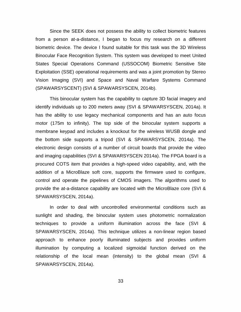
33
Since the SEEK does not possess the ability to collect biometric features
from a person at-a-distance, I began to focus my research on a different
biometric device. The device I found suitable for this task was the 3D Wireless
Binocular Face Recognition System. This system was developed to meet United
States Special Operations Command (USSOCOM) Biometric Sensitive Site
Exploitation (SSE) operational requirements and was a joint promotion by Stereo
Vision Imaging (SVI) and Space and Naval Warfare Systems Command
(SPAWARSYSCENT) (SVI & SPAWARSYSCEN, 2014b).
This binocular system has the capability to capture 3D facial imagery and
identify individuals up to 200 meters away (SVI & SPAWARSYSCEN, 2014a). It
has the ability to use legacy mechanical components and has an auto focus
motor (175m to infinity). The top side of the binocular system supports a
membrane keypad and includes a knockout for the wireless WUSB dongle and
the bottom side supports a tripod (SVI & SPAWARSYSCEN, 2014a). The
electronic design consists of a number of circuit boards that provide the video
and imaging capabilities (SVI & SPAWARSYSCEN 2014a). The FPGA board is a
procured COTS item that provides a high-speed video capability, and, with the
addition of a MicroBlaze soft core, supports the firmware used to configure,
control and operate the pipelines of CMOS imagers. The algorithms used to
provide the at-a-distance capability are located with the MicroBlaze core (SVI &
SPAWARSYSCEN, 2014a).
In order to deal with uncontrolled environmental conditions such as
sunlight and shading, the binocular system uses photometric normalization
techniques to provide a uniform illumination across the face (SVI &
SPAWARSYSCEN, 2014a). This technique utilizes a non-linear region based
approach to enhance poorly illuminated subjects and provides uniform
illumination by computing a localized sigmoidal function derived on the
relationship of the local mean (intensity) to the global mean (SVI &
SPAWARSYSCEN, 2014a).
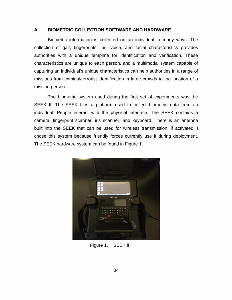
34
A. BIOMETRIC COLLECTION SOFTWARE AND HARDWARE
Biometric information is collected on an individual in many ways. The
collection of gait, fingerprints, iris, voice, and facial characteristics provides
authorities with a unique template for identification and verification. These
characteristics are unique to each person, and a multimodal system capable of
capturing an individual’s unique characteristics can help authorities in a range of
missions from criminal/terrorist identification in large crowds to the location of a
missing person.
The biometric system used during the first set of experiments was the
SEEK II. The SEEK II is a platform used to collect biometric data from an
individual. People interact with the physical interface. The SEEK contains a
camera, fingerprint scanner, iris scanner, and keyboard. There is an antenna
built into the SEEK that can be used for wireless transmission, if activated. I
chose this system because friendly forces currently use it during deployment.
The SEEK hardware system can be found in Figure 1.
Figure 1. SEEK II
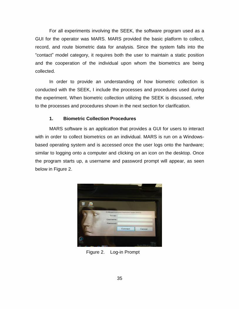
35
For all experiments involving the SEEK, the software program used as a
GUI for the operator was MARS. MARS provided the basic platform to collect,
record, and route biometric data for analysis. Since the system falls into the
“contact” model category, it requires both the user to maintain a static position
and the cooperation of the individual upon whom the biometrics are being
collected.
In order to provide an understanding of how biometric collection is
conducted with the SEEK, I include the processes and procedures used during
the experiment. When biometric collection utilizing the SEEK is discussed, refer
to the processes and procedures shown in the next section for clarification.
1. Biometric Collection Procedures
MARS software is an application that provides a GUI for users to interact
with in order to collect biometrics on an individual. MARS is run on a Windows-
based operating system and is accessed once the user logs onto the hardware;
similar to logging onto a computer and clicking on an icon on the desktop. Once
the program starts up, a username and password prompt will appear, as seen
below in Figure 2.
Figure 2. Log-in Prompt

36
Once the correct information is entered, the program opens to a menu that
provides a multitude of options such as enrollment, practice mode, import and
export options for files, history and statistics, search, and presets. Each one of
these categories has sub-sections that provide multiple tools for biometrics
collection. These tools guide the user in the process of collection and ensure
important information is captured.
The home page for MARS provides multiple user options. The enrollment
tab allows the user to begin the process for collecting biometrics on an individual.
Practice mode is used to provide realistic training on the software and processes
behind data collection. Practice mode prevents an individual’s biometrics from
accidently end up in IAFIS and on a hit list. The import and export tab enables
the transfer of profiles in the form of EFT files from the biometric system to IAFIS.
These files are uploaded to a database, i.e. IAFIS or SOFEX portal, in order to
check for matches against existing profiles and to record new entries. The history
and statistics tab provides information on the number of people on a watch list,
number of alerts based on information collected, and dossiers. This section also
keeps a count of the amount of enrollments in a seven-day period. The search
enables the user to lookup a pre-existing record via fingerprints, iris, or name.
The presets allow a user to go into the sub-sections used for collection and tailor
them for specific criteria. Figure 3 displays the categories available to users on
the home page.
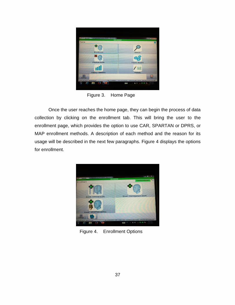
37
Figure 3. Home Page
Once the user reaches the home page, they can begin the process of data
collection by clicking on the enrollment tab. This will bring the user to the
enrollment page, which provides the option to use CAR, SPARTAN or DPRS, or
MAP enrollment methods. A description of each method and the reason for its
usage will be described in the next few paragraphs. Figure 4 displays the options
for enrollment.
Figure 4. Enrollment Options

38
The CAR enrollment option is used for criminal types of personnel and
EPWs (DOD, 2006). CAR enrollments require both flat or slap prints and rolled
fingerprint images (Crossmatch, 2014). CAR transactions are done at more
secure facilities inside the wire.
DOD (2006) describes the DPRS enrollment process and how it is used
when acquiring rolled fingerprints is not possible. DPRS enrollment accepts flat
fingerprint as well as rolled prints, which provides the user a more capable option
for biometric enrollment in an austere environment. Hasty DPRS enrollment
collects ten fingerprints where tactical DPRS may be used to collect flat thumb
and index prints due to limited bandwidth (Crossmatch, 2014). This enrollment is
typically used by the DOD and take place outside the wire (Crossmatch, 2014).
Background checks on non-U.S. personnel that desire access to military
installations and restricted areas is done using the MAP enrollment option, which
requires both flat and rolled prints (DOD, 2006) This provides the user with the
capability to capture very accurate fingerprint images, which makes identification
easier.
For the purposes of all experiments, DPRS enrollment is used for all
experimentation. This option was picked because the time and cooperation
necessary to acquire fully rolled or flat images in an austere environment is not
feasible.
When the user clicks the DPRS enrollment option, a list of biometric
collection options will appear. The user can choose to capture an individual’s
fingerprints, photograph, irises, personal data and enrollment location. Figure 5
shows the options listed on the DPRS page.

39
Figure 5. DPRS Biometric Enrollment Page
a. Fingerprinting
The fingerprint tab provides a platform for the user to collect the
fingerprints of an individual. Once the tab is opened, ten slots will appear, each
representing a finger. The user can click on specific fingers to scan or scan all
fingers in sequence based on the program’s preset process of collection. If an
individual is missing a finger or has an identifying mark, the user can notate this
by clicking the “missing” button and following the prompts.
Once the collection process begins, the user can begin scanning each
finger using the scan box located at the bottom of the device. The program will
indicate a successful scan with a beep, followed by a copy of the fingerprint in its
designated slot. If there are any issues with the print, it will be notated at the
bottom left with an error. Once all fingers are scanned, the program will show the
fingerprinting process as complete and the user can move onto the next
collection effort. Figures 6 and 7 show the scanner and biometric slots,
respectively.
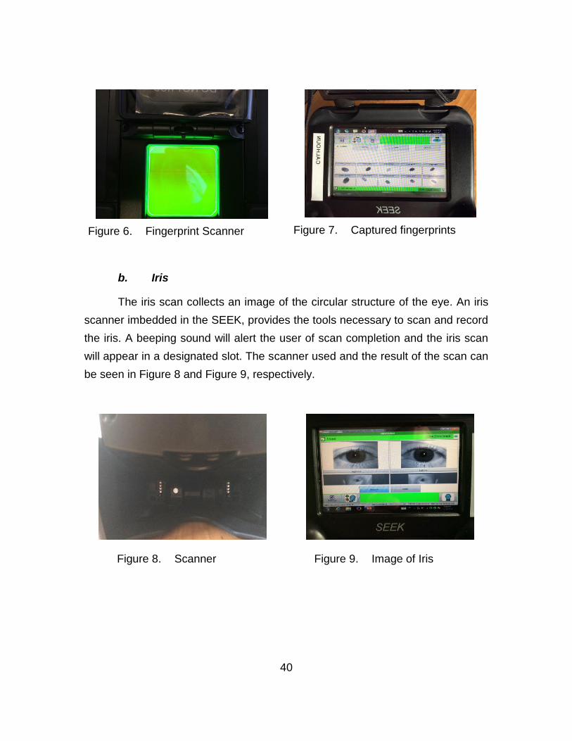
40
Figure 6. Fingerprint Scanner
Figure 7. Captured fingerprints
b. Iris
The iris scan collects an image of the circular structure of the eye. An iris
scanner imbedded in the SEEK, provides the tools necessary to scan and record
the iris. A beeping sound will alert the user of scan completion and the iris scan
will appear in a designated slot. The scanner used and the result of the scan can
be seen in Figure 8 and Figure 9, respectively.
Figure 8. Scanner
Figure 9. Image of Iris

41
c. Facial Recognition
The facial recognition tab provides the user with a tool to capture an
individual’s facial structure from multiple directions. The user will have the option
of capturing the face of an individual from the front, left, right, at 45 degrees
facing the left, and at 45 degrees facing to the right. This provides an in depth
view of the facial characteristics of an individual. Pictures are taken using a
camera imbedded in the SEEK. The pictures are taken within a distance of about
a meter from the biometric device. Figure 10 shows the facial recognition setup
for all angles.
Figure 10. Facial Recognition
d. Personal Data
The personal data tab provides the user with a way to add descriptive
information about the subject being enrolled. This information consists of family
name, date of birth, and other physical characteristics along with the reason for
enrollment. The digital keypad or keypad located on the SEEK; can be used to
complete all data fields. Figure 11 provides a snapshot of the data entry fields.
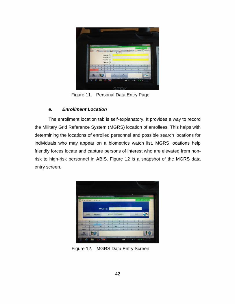
42
Figure 11. Personal Data Entry Page
e. Enrollment Location
The enrollment location tab is self-explanatory. It provides a way to record
the Military Grid Reference System (MGRS) location of enrollees. This helps with
determining the locations of enrolled personnel and possible search locations for
individuals who may appear on a biometrics watch list. MGRS locations help
friendly forces locate and capture persons of interest who are elevated from non-
risk to high-risk personnel in ABIS. Figure 12 is a snapshot of the MGRS data
entry screen.
Figure 12. MGRS Data Entry Screen
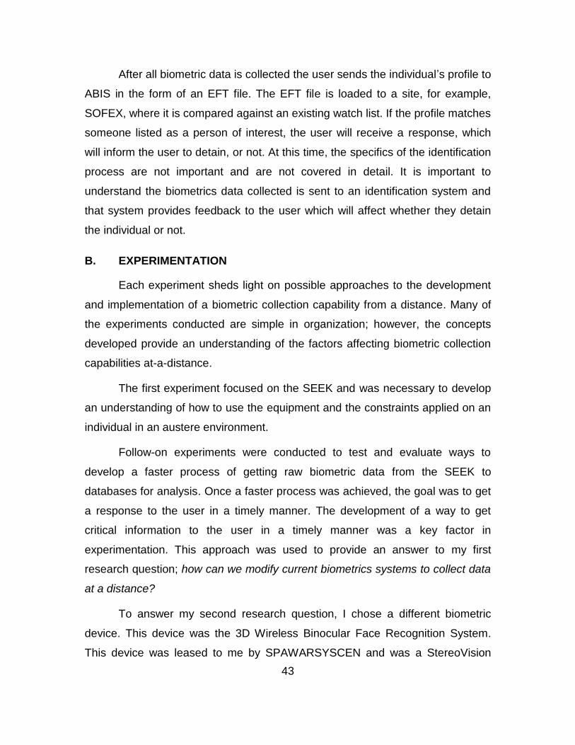
43
After all biometric data is collected the user sends the individual’s profile to
ABIS in the form of an EFT file. The EFT file is loaded to a site, for example,
SOFEX, where it is compared against an existing watch list. If the profile matches
someone listed as a person of interest, the user will receive a response, which
will inform the user to detain, or not. At this time, the specifics of the identification
process are not important and are not covered in detail. It is important to
understand the biometrics data collected is sent to an identification system and
that system provides feedback to the user which will affect whether they detain
the individual or not.
B. EXPERIMENTATION
Each experiment sheds light on possible approaches to the development
and implementation of a biometric collection capability from a distance. Many of
the experiments conducted are simple in organization; however, the concepts
developed provide an understanding of the factors affecting biometric collection
capabilities at-a-distance.
The first experiment focused on the SEEK and was necessary to develop
an understanding of how to use the equipment and the constraints applied on an
individual in an austere environment.
Follow-on experiments were conducted to test and evaluate ways to
develop a faster process of getting raw biometric data from the SEEK to
databases for analysis. Once a faster process was achieved, the goal was to get
a response to the user in a timely manner. The development of a way to get
critical information to the user in a timely manner was a key factor in
experimentation. This approach was used to provide an answer to my first
research question; how can we modify current biometrics systems to collect data
at a distance?
To answer my second research question, I chose a different biometric
device. This device was the 3D Wireless Binocular Face Recognition System.
This device was leased to me by SPAWARSYSCEN and was a StereoVision

44
Imagining (SVI) and SPAWARSYSCEN Atlantic (SSC Atlantic) initiative. The
primary focus of the development of the binoculars was to provide
USSOCOM/SOF with long-range standoff identification (200 meters) of non-
cooperative subjects and “suspect objects of interest” in uncontrolled daylight
environments using intrinsic 3D image data (SVI & SPAWARSYSCEN, 2014a).
With this device, I attempt to answer the following question: How can biometric
sensor output be used to enhance biometric awareness in a hostile environment?
Table 3 provides a description of the experiments conducted in the context
explained in (Alberts & Hayes, 2002).
Table 3. Experimentation Theory of Practice (after Alberts & Hayes, 2002)
Experiment Experiment Type
Location Purpose Objective Dates
1 Discovery Gdansk, Poland
Identify the typical environment for the use of the SEEK.
Understand how the SEEK is used.
May 2014
2 Hypothesis Alameda, CA
Evaluate the strains placed on the MANET and factors that would affect its establishment and stability.
Understand how a network could affect data transfer.
Aug 2014
3 Hypothesis Alameda, CA
Determine whether biometric data could be sent over a MANET to a biometric database for match/no match confirmation.
Determine whether or not biometric data transfer over a MANET is feasible.
Oct 2014
4 Demonstration Monterey, CA
Demonstrate that a device can conduct at-a-distance biometric data collection.
Demonstrate that an “at-a-distance” biometric capability exists and is useful to the tactical warfighter
March-June 2014
1. Experiment #1: WMD-ISR Exercise in Gdansk, Poland
This experiment was conducted during the International Weapons of Mass
Destruction Intelligence, Surveillance, and Reconnaissance experimentation
program that took place from 6–12 May 2014 in Gdansk, Poland. The purpose of
this experiment was to identify the typical environment necessary to conduct
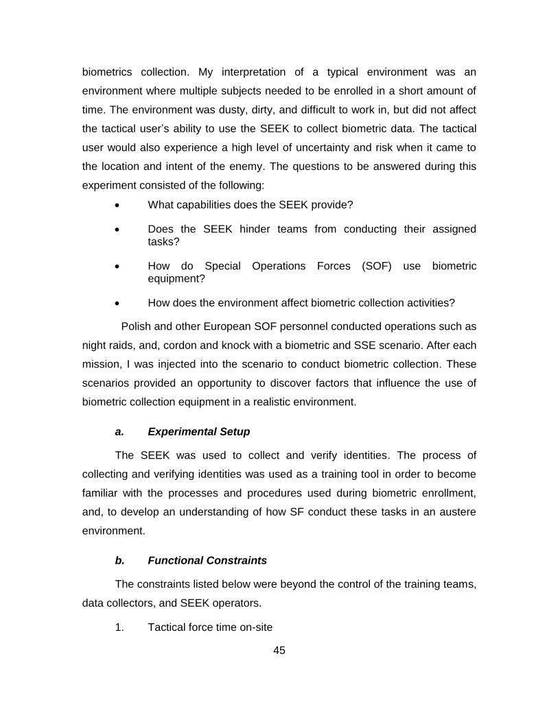
45
biometrics collection. My interpretation of a typical environment was an
environment where multiple subjects needed to be enrolled in a short amount of
time. The environment was dusty, dirty, and difficult to work in, but did not affect
the tactical user’s ability to use the SEEK to collect biometric data. The tactical
user would also experience a high level of uncertainty and risk when it came to
the location and intent of the enemy. The questions to be answered during this
experiment consisted of the following:
What capabilities does the SEEK provide?
Does the SEEK hinder teams from conducting their assigned tasks?
How do Special Operations Forces (SOF) use biometric equipment?
How does the environment affect biometric collection activities?
Polish and other European SOF personnel conducted operations such as
night raids, and, cordon and knock with a biometric and SSE scenario. After each
mission, I was injected into the scenario to conduct biometric collection. These
scenarios provided an opportunity to discover factors that influence the use of
biometric collection equipment in a realistic environment.
a. Experimental Setup
The SEEK was used to collect and verify identities. The process of
collecting and verifying identities was used as a training tool in order to become
familiar with the processes and procedures used during biometric enrollment,
and, to develop an understanding of how SF conduct these tasks in an austere
environment.
b. Functional Constraints
The constraints listed below were beyond the control of the training teams,
data collectors, and SEEK operators.
1. Tactical force time on-site
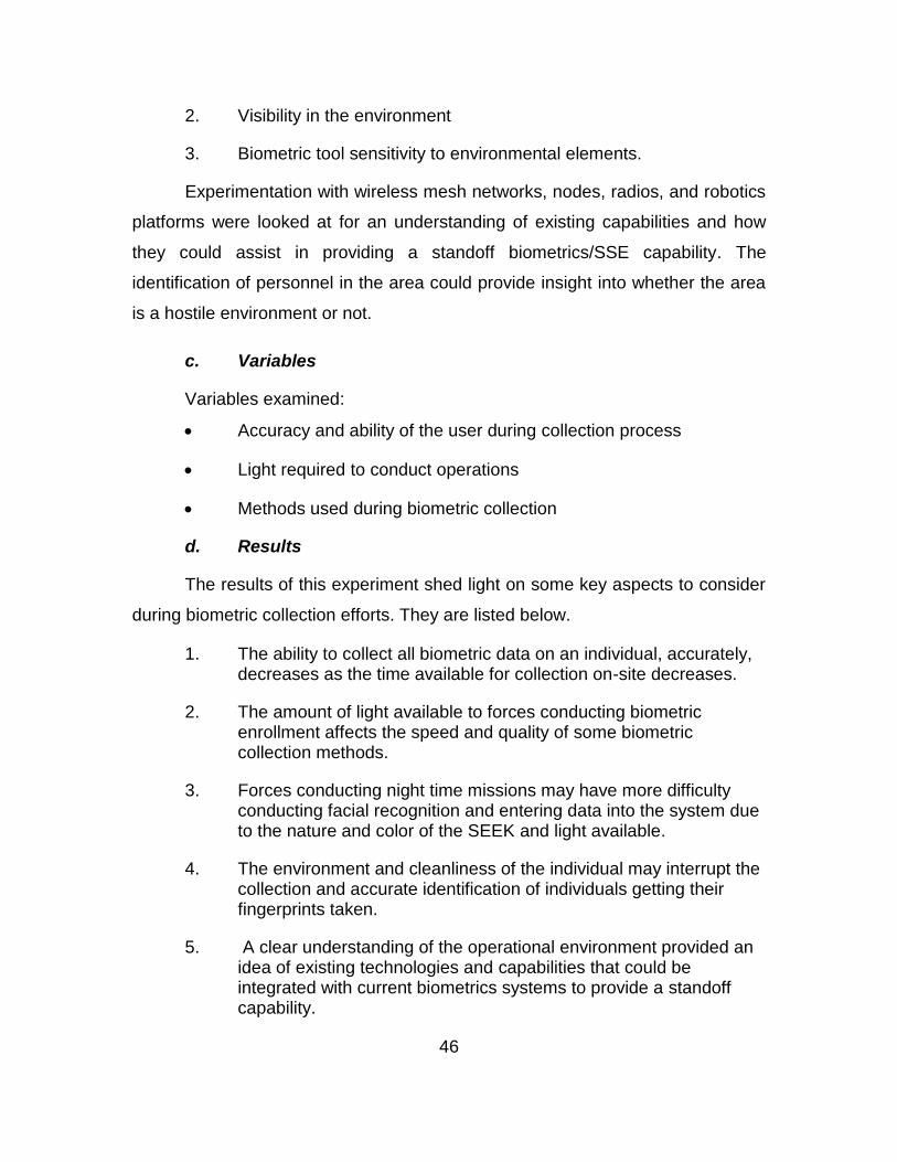
46
2. Visibility in the environment
3. Biometric tool sensitivity to environmental elements.
Experimentation with wireless mesh networks, nodes, radios, and robotics
platforms were looked at for an understanding of existing capabilities and how
they could assist in providing a standoff biometrics/SSE capability. The
identification of personnel in the area could provide insight into whether the area
is a hostile environment or not.
c. Variables
Variables examined:
Accuracy and ability of the user during collection process
Light required to conduct operations
Methods used during biometric collection
d. Results
The results of this experiment shed light on some key aspects to consider
during biometric collection efforts. They are listed below.
1. The ability to collect all biometric data on an individual, accurately, decreases as the time available for collection on-site decreases.
2. The amount of light available to forces conducting biometric enrollment affects the speed and quality of some biometric collection methods.
3. Forces conducting night time missions may have more difficulty conducting facial recognition and entering data into the system due to the nature and color of the SEEK and light available.
4. The environment and cleanliness of the individual may interrupt the collection and accurate identification of individuals getting their fingerprints taken.
5. A clear understanding of the operational environment provided an idea of existing technologies and capabilities that could be integrated with current biometrics systems to provide a standoff capability.

47
6. The Maritime-Land WMD-ISR field exercise provided insight into real life applications of biometrics collection.
7. Biometric data collection could enhance situational awareness on a target and provide a common operational picture of what to expect when entering the area.
These findings will be analyzed in chapter IV.
2. Experiment #2: Joint Interagency Field Exercise in Alameda, CA
This experiment was conducted during Joint Interagency Field Exercise in
August 2014 at the Alameda shipyard in California. The experiment consisted of
members of the Coast Guard, Marines, and private contractors who were testing
a variety of technologies for WMD detection, wireless communications, efficient
information transfer over wireless mesh networks, and mobile node limitations in
an austere environment. Key portions of this experiment occurred onboard the
GTS Adm. Callaghan (AK-1001), which served as the experiment’s boarded
vessel (Sinsel, 2015). The purpose of this experiment was to evaluate the strains
placed on the MANET and factors that would affect its establishment and
stability. The questions to be answered during this experiment consisted of the
following:
What factors affected the efficiency of a MANET?
What equipment was necessary to overcome strains on the MANET?
a. Experimental Setup
The equipment used for this experiment consisted of multiple Wave Relay
(WR) and Trellisware (TW) mobile tactical radios, WR Quad radio utilizing 360°
sector array antenna with 8 dBI gain, WR MPU4 radios, a laptop computer, and
multiple USCG and SFPD vessels (Sinsel, 2015).
The computer and WR Quad radio were set up on the GTS Adm.
Callaghan, which acted as the command post. A communications station located
on Yerba Buena Island (YBI) operated as a remote Command and Control (C2)

48
station and one USCG and one SFPD vessel, each equipped with a wave relay
radio, acted as relay nodes between the C2 station and the Callaghan (Sinsel,
2015)
b. Functional Constraints
The constraints listed below were beyond the control of the training teams,
data collectors, and operators.
1. Number of vessels available to act as a mobile node
2. Platforms available to establish a MANET
Experimentation with wireless mesh networks, nodes, radios, and robotics
platforms were looked at for an understanding of existing capabilities and how
they could assist in providing a standoff biometrics/SSE capability. The
identification of personnel in the area could provide insight into whether the area
is a hostile environment or not.
c. Variables
The variables examined during this experiment are listed below.
1. Range and coverage of an area based on the position of mobile nodes.
2. Load placed on the MANET.
d. Results
The results of this experiment shed light on some key aspects to consider
during biometric collection efforts. They are listed below.
1. Increase range, reduce latency and error rate, and increase data rates.
2. Implementation of a directional high gain antenna on the boarding vessel would be required.
3. Selection of the radio equipment with sufficient output power is important to the success of the network. Recommend two W WR models.
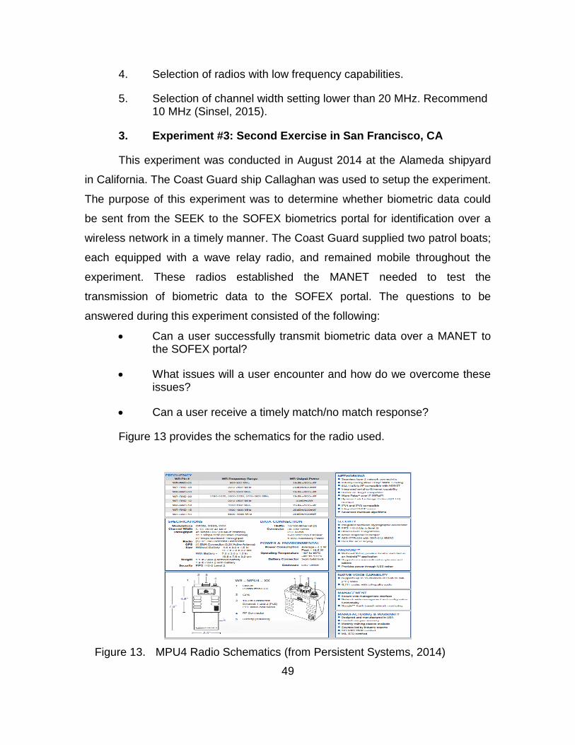
49
4. Selection of radios with low frequency capabilities.
5. Selection of channel width setting lower than 20 MHz. Recommend 10 MHz (Sinsel, 2015).
3. Experiment #3: Second Exercise in San Francisco, CA
This experiment was conducted in August 2014 at the Alameda shipyard
in California. The Coast Guard ship Callaghan was used to setup the experiment.
The purpose of this experiment was to determine whether biometric data could
be sent from the SEEK to the SOFEX biometrics portal for identification over a
wireless network in a timely manner. The Coast Guard supplied two patrol boats;
each equipped with a wave relay radio, and remained mobile throughout the
experiment. These radios established the MANET needed to test the
transmission of biometric data to the SOFEX portal. The questions to be
answered during this experiment consisted of the following:
Can a user successfully transmit biometric data over a MANET to the SOFEX portal?
What issues will a user encounter and how do we overcome these issues?
Can a user receive a timely match/no match response?
Figure 13 provides the schematics for the radio used.
Figure 13. MPU4 Radio Schematics (from Persistent Systems, 2014)
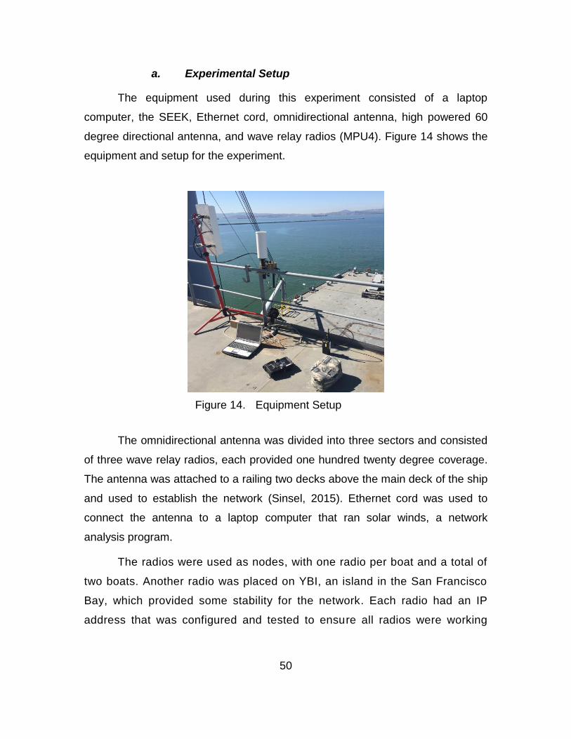
50
a. Experimental Setup
The equipment used during this experiment consisted of a laptop
computer, the SEEK, Ethernet cord, omnidirectional antenna, high powered 60
degree directional antenna, and wave relay radios (MPU4). Figure 14 shows the
equipment and setup for the experiment.
Figure 14. Equipment Setup
The omnidirectional antenna was divided into three sectors and consisted
of three wave relay radios, each provided one hundred twenty degree coverage.
The antenna was attached to a railing two decks above the main deck of the ship
and used to establish the network (Sinsel, 2015). Ethernet cord was used to
connect the antenna to a laptop computer that ran solar winds, a network
analysis program.
The radios were used as nodes, with one radio per boat and a total of
two boats. Another radio was placed on YBI, an island in the San Francisco
Bay, which provided some stability for the network. Each radio had an IP
address that was configured and tested to ensure all radios were working
51
and ready to carry data over the network. Figure 15 provides an idea of how
far the island was from our location.
Figure 15. Island with Wave Relay Radio
b. Functional Constraints
The constraints listed below were beyond the control of the training teams,
data collectors, and operators.
1. Number of vessels available to act as a mobile node
2. Platforms available to establish a MANET
3. Time on station for all supporting patrol boats
c. Variables
The variables examined during this experiment are listed below.
1. CENETIX server and SOFEX biometric portal connectivity (Sinsel, 2015)
2. Achievement of a match/no match response from the SOFEX portal via a wireless mesh network.
Island with radio

52
3. The time it took to send and receiving biometric data via a MANET would determine if it was feasible for ground forces to use a MANET for biometrics identification in an austere environment.
4. Wireless models to access SOFEX
There were two wireless models for the SEEK II to connect to both the
CENETIX and SOFEX portals. The first one consisted of enabling a WAP on a
MPU4 and then connecting the SEEK to the WAP (Sinsel, 2015). The second
consisted of tethering the SEEK II to the MPU4 with Ethernet cables (Sinsel,
2015). For the purposes of this research, we viewed the tethered device, which
allowed for operator mobility, as one wireless device (Sinsel, 2015).
d. Results
The results of this experiment are listed below.
1. Adding a WR 802.11 WAP provided wireless connectivity to the SEEK II enabling biometric enrollment data transmission (XML or EFT files) (Sinsel, 2015)
2. Match/no match criteria responses were received from the SOFEX portal with 2–3 minute latency.
3. A match/no match response was received using the tethered method (Sinsel, 2015).
4. Biometric data sharing via a wireless capability was successful (Sinsel, 2015).
5. Tethered operations were fast than the WAP on a MPU4 (Sinsel, 2015).
6. A static route on a VPN router simultaneously provided reach back and protected the network (Sinsel, 2015).
7. The default settings of the SEEK II operating system, Windows XP, enabled a windows firewall when windows explorer was activated. This issue interfered with access to the Internet and was circumvented by the use of Firefox. Although the default settings on explorer were turned off and multiple attempts were made using explorer, Firefox provided the best result for access to the Internet.

53
4. Experiment #4: Experiment with 3D binoculars
This experiment was conducted from March to June of 2015 at the
CENETIX lab at the Naval Postgraduate School in California. The purpose of this
experiment was to conduct a proof of concept and develop an understanding of
how the 3D Wireless Binocular system works. I utilized all items provided: a
laptop, portable 5VDC battery and charger, and a custom USB cord. I acquired a
tripod stand to mount the binoculars for stability and began to configure the
software based off the manual provided. The questions to be answered during
this experiment consisted of the following:
Can the 3D Wireless Binocular System identify an individual?
What issues will a user encounter and how do we overcome these issues?
Are we able to receive a timely match/no match response?
a. Experimental Setup
Once all items were unpacked and accounted for, the laptop computer
was used to set up all applications to support biometric collection activities. The
binoculars were mounted on a tripod with a connection to a portable power
supply, and, a connection to the laptop. Based on the user manual procedures,
powering the device from a power jack on the wall would cause damage to the
facial recognition chips that hold the algorithms (SVI & SPAWARSYSCEN,
2014b). For this reason, the device was powered from the portable power supply
only. Figure 16 is a display of the setup.

54
Figure 16. Biometric System Setup and Interoperability
The graphical user interface (GUI) used to operate the binocular system
has the capability to communicate between the laptop and binoculars, enhance
captured video and imagery, and serve to any COTS face matcher with an http
interface (Schulz, 2015). The captured video can be saved and served to the
Alarm Center where it can be viewed as well as the identification results (Schulz,
2015).
The face recognition software has the capability to verify and identify a
subject based on photos contained in the database (Schulz, 2015). Figures 17
and 18 show identification and verification of a subject.
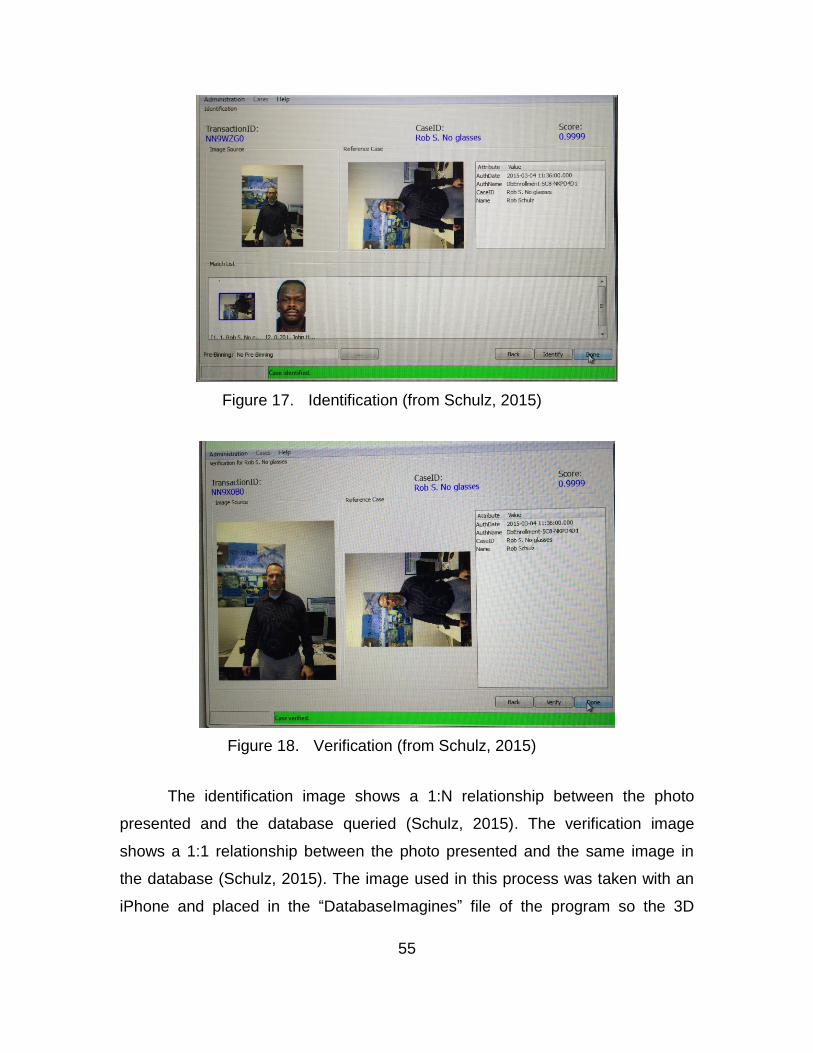
55
Figure 17. Identification (from Schulz, 2015)
Figure 18. Verification (from Schulz, 2015)
The identification image shows a 1:N relationship between the photo
presented and the database queried (Schulz, 2015). The verification image
shows a 1:1 relationship between the photo presented and the same image in
the database (Schulz, 2015). The image used in this process was taken with an
iPhone and placed in the “DatabaseImagines” file of the program so the 3D

56
Mobile software application could access the image and conduct identification
and verification procedures (Schulz, 2015). The process of placing the photo in
this file was part of the instructions listed in the Manual (SVI &
SPAWARSYSCEN, 2014b). Figure 19 is a snapshot of this process.
Figure 19. Placement of Image for Recognition (from Schulz, 2015)
Now that the system was set up and my image was inserted into the
correct folder, the process of conducting biometric collection and analysis for
identification could begin.
b. Variables
The variables examined during this experiment are listed below.
1. Accuracy of the facial recognition software
2. Distance of facial recognition
The variables listed were picked to be tested in order to establish that the
device worked, identify the limitations of the device, and, the factors that could be
changed to provide positive and negative effects on the collection and
identification of my facial characteristics.
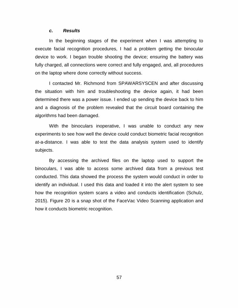
57
c. Results
In the beginning stages of the experiment when I was attempting to
execute facial recognition procedures, I had a problem getting the binocular
device to work. I began trouble shooting the device; ensuring the battery was
fully charged, all connections were correct and fully engaged, and, all procedures
on the laptop where done correctly without success.
I contacted Mr. Richmond from SPAWARSYSCEN and after discussing
the situation with him and troubleshooting the device again, it had been
determined there was a power issue. I ended up sending the device back to him
and a diagnosis of the problem revealed that the circuit board containing the
algorithms had been damaged.
With the binoculars inoperative, I was unable to conduct any new
experiments to see how well the device could conduct biometric facial recognition
at-a-distance. I was able to test the data analysis system used to identify
subjects.
By accessing the archived files on the laptop used to support the
binoculars, I was able to access some archived data from a previous test
conducted. This data showed the process the system would conduct in order to
identify an individual. I used this data and loaded it into the alert system to see
how the recognition system scans a video and conducts identification (Schulz,
2015). Figure 20 is a snap shot of the FaceVac Video Scanning application and
how it conducts biometric recognition.
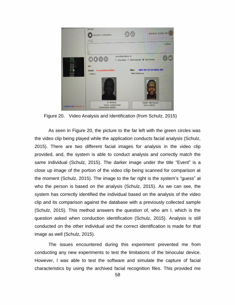
58
Figure 20. Video Analysis and Identification (from Schulz, 2015)
As seen in Figure 20, the picture to the far left with the green circles was
the video clip being played while the application conducts facial analysis (Schulz,
2015). There are two different facial images for analysis in the video clip
provided, and, the system is able to conduct analysis and correctly match the
same individual (Schulz, 2015). The darker image under the title “Event” is a
close up image of the portion of the video clip being scanned for comparison at
the moment (Schulz, 2015). The image to the far right is the system’s “guess” at
who the person is based on the analysis (Schulz, 2015). As we can see, the
system has correctly identified the individual based on the analysis of the video
clip and its comparison against the database with a previously collected sample
(Schulz, 2015). This method answers the question of, who am I, which is the
question asked when conduction identification (Schulz, 2015). Analysis is still
conducted on the other individual and the correct identification is made for that
image as well (Schulz, 2015).
The issues encountered during this experiment prevented me from
conducting any new experiments to test the limitations of the binocular device.
However, I was able to test the software and simulate the capture of facial
characteristics by using the archived facial recognition files. This provided me

59
with an understanding of how the system worked and that it was capable of
capturing facial characteristics at-a-distance. This concluded my experimentation
for this thesis.

60
THIS PAGE INTENTIONALLY LEFT BLANK
61
IV. DATA ANALYSIS
This chapter will cover my interpretation of the results of each experiment.
I will explain how my findings in each experiment added to my understanding of
the situation and my actions in future experiments.
A. BRIEF OVERVIEW
The experiments conducted were used as an attempt to discover whether
a biometric collection capability, at-a-distance, was a viable concept, given the
resources and equipment available to both friendly forces and myself. The results
obtained through the sequence of experimentation were derived while multiple
student experiments were taking place, in a time consuming environment, with
multiple participants and multiple agendas.
Each section will discuss the results mentioned in chapter III. Each
experiment is analyzed to develop a perspective on biometric collection methods
and techniques, and, how I formulated decisions for future experiments.
1. WMD-ISR Exercise in Gdansk, Poland
Throughout the WMD-ISR exercise, the time available to prepare and
conduct biometric collection became constrained. This was due to the
operational tempo and scenario injections that provided the feeling of a real
mission. This issue affected the conduct of biometric collection methods because
all biometric equipment needed to be ready and available immediately upon
arrival on-site. The need to be ready at a moment’s notice meant that all
equipment needed to be fully charged and backup power supplies needed to be
kept at 100% in order to meet the need for long-term biometric collection efforts.
All equipment needed to be setup on the enrollment page so that when we
arrived on-site we could immediately begin enrollment. This was critical because
the system took about 5 minutes to turn on and to log into. The system also has
a sleep mode and if left alone for enough time, turns itself off. This would be

62
counterproductive in an environment where time was scarce and the
environment was hostile.
In order to mitigate the loss of time and biometric collection opportunities,
the SEEK was kept on and spare batteries were brought to ensure ample time for
enrollment. I frequently checked the system to ensure it did not go into sleep
mode or turn off from lack of use. Once the SEEK was on, I logged into the
MARS system and ensured the system was already set on the enrollment page.
Any generic data that could have been entered prior to our departure to the site
was already inserted into the appropriate box. The only issue with this method
was that the screen on the SEEK was very bright and detectable to anyone in the
vicinity. This could be an issue if there was a need to remain covert.
Although light may be a burden when trying to remain covert, the ability to
conduct biometric collection with little or no light caused many issues. As I
experienced during one scenario, the building we entered was pitch dark with
very little or no light. This made it difficult to move around let alone identify
personnel for biometric enrollment. The time during which I could conduct
biometric enrollment was reduced, which required a longer time on-site in order
to complete all enrollments. Facial images were difficult to capture and due to the
high tempo of the operation, I was unable to collect the five pictures required to
complete a full facial profile. Iris and fingerprint scanning did not present much of
a problem; however, the ability to identify marks on an individual that might be
important was nearly impossible unless it was easily noticeable when close to the
subject.
These observations provided insight into what combat forces might
encounter when conducting operations at night and in austere environments. I
realized that biometric collection methods required the user to spend more time
ensuring the biometric collection data was accurate. This shortened the time
available for a user to utilize the multiple biometric collect methods available, and
collect the biometric data necessary to create or verify an individual in a biometric
database.

63
In order to counter this challenge, the best course of action was to get as
much information as possible and as much biometric data as possible. When
unable to collect facial images, I moved to the collection of fingerprints, iris, and
any information I could enter manually into the system such as name, location,
date of birth, birthplace, etc. In some cases, the only way to collect the biometrics
was to use a flashlight. Although not very covert, it still provided the opportunity
to collect data on the subject. As a result, training teams would need to move
quickly through the objective to try to reduce the light signature given off by the
SEEK so they could avoid drawing attention to their activities and as a result,
accept the risk of being spotted by enemy forces.
A major issue affecting accurate biometric enrollment was the cleanliness
of the environment and the individual being enrolled. Dirt in the environment
could damage or affect the instruments on the SEEK used for facial, iris, and
fingerprint collection. This was especially true for the fingerprint scanner that was
sensitive to dirt and other materials interfering with the scanning platform. As for
the cleanliness of the individual, facial scans and fingerprinting could be affected.
As with many areas of operation, the individual is exposed to the elements of the
environment. In many cases, the individual may have dirt on his face and fingers,
making it difficult for the biometric scanners to recognize and record biometrics.
The need to clean the equipment and individual is time consuming and puts a
strain on the need to be hasty and covert. As a result, training teams would need
to accept the risk of remaining on-site, stationary, and exposed to possible
enemy ambushed with little or no supporting capabilities.
In order to resolve these issues, the subject who needed to be scanned
was moved outside of the building and quickly wiped down to ensure the process
of biometric enrollment went smoothly. Proper protection and insolation of the
scanning surfaces assisted with the dirt collection and interference with biometric
enrollment equipment. All areas of the individual that had heavy amounts of dirt
on them were wiped down in order to collect all the major characteristics of that
individual. Dirt under the eyes, on cheeks, and major contours of the face were

64
removed to provide an accurate depiction of the individual’s facial features. All
fingers were wiped down to ensure the fingerprint scanner could accurately
collect the minutia of the fingers. All of this was time consuming, nevertheless,
necessary.
Throughout the exercise, I kept alert for opportunities to collect biometrics
from individuals. I thought of the concept of “at-a-distance” biometrics from two
perspectives;
Can I collect the biometrics from an individual without the need to be in their proximity?
Can I collect an individual’s biometrics in proximity but get a timely and accurate response from ABIS without having to return to base and load the biometric collections into the system?
This led me to look into UGVs and their capabilities. The issues I
identified with using UGVs was the need to configure software to analyze
biometric data from an individual using video feed. This data would also need to
be transmitted wirelessly. Another issue with UGVs is that they’re invasive and
may not be in a good position to capture biometric traits the way we normally do
it; i.e., facial scans from 5 different directions or fingerprints up close.
The analysis of the results of this experiment led me to pursue two
possible “at-a-distance” approaches. The first would be to collect biometrics at a
physical distance; the individual has no idea I am collecting their biometrics
because I am not physically there to collect it. A device or camera of sorts would
be used to collect characteristics that could be analyzed by biometric software.
The second would be to collect biometrics at the physical location but avoid the
need to return to base to upload the data to a database for verification. This was
done by sending the data, wirelessly, to the database providing a way for friendly
forces to remain on-site and receive analyzed biometric data within a timely
manner so they could act on it.
The former would address the vulnerability of physically collecting
biometrics on individuals that may potentially be hostile, in a potentially hostile
65
environment, and, was my primary goal during the evolution of this thesis. The
latter would address the need to release enrolled individuals and return to base
to load and verify biometrics data, only to find out hours later that one or many of
the individuals you detained were high priority targets. Both capabilities address
the need to get information in a timely manner.
Therefore, the idea of capturing the data up close and sending it to the
Special Operations Force Exhibition (SOFEX) database wirelessly might still
provide “at-a-distance” advantages because it would not require forces to leave
the area of operations to transmit the data. Although users would still need to
collect biometrics on-site, the delivery of data would be done through wireless
communication. This eliminates the need for friendly forces to release suspects
and return to base to upload biometric data. Friendly forces could remain on-site
and receive identification of personnel in near real-time, providing them with the
capability to act immediately. This possibility led to my next experiment.
2. Joint Interagency Field Exercise in San Francisco, CA, August 2014
Given the limitations of the SEEK as observed during experiment #1, to
collect biometric data “at-a-distance,” I pursued my second interpretation of “at-a-
distance” by utilizing a wireless network as a reach back capability.
The focus of this experiment was to determine whether a MANET could be
used to send data files from the SEEK to the SOFEX portal for identification. Due
to time constraints, we were unable to test biometric data transmission over the
MANET. We were able to evaluate how a MANET would work and the
capabilities and limitations placed on the network when a data load was placed
on the network.
We found that an increase in range would be needed to reduce latency
and error rates, and, to increase data rates to enable biometric data transmission
(Sinsel, 2015). The addition of a directional high gain antenna would provide the
necessary power to meet all required rates and ranges (Sinsel, 2015). This
66
modification is necessary for expedient transfer of biometric data to the SOFEX
portal to ensure the end user could upload data and receive a match/no match
response from the database in a timely manner. The size of the EFT files and the
number of files transmitted to the SOFEX portal would require a network with
reduced latency, error rates, and increased data rates in order to provide
accurate and near-real responses from the SOFEX database. This is critical for
users far from base with no system to plug into to upload data.
The ability to send and receive data in a timely manner over a wireless
network, while on-site, enabled end users to act on information received in near-
real time. The increased range would allow users to access the SOFEX portal
watch list which is larger, and capable of maintaining more records than the
storage space allotted on the SEEK, resulting in a more refined and up-to-date
search for subjects.
The recommended 2 Watt WR models for the radios in the MANET and
channel selection width setting lower than 20 MHZ helped with the transmission
of data to the SOFEX portal which enabled the user to send and receive data for
analysis, and, receive a response in near-real time. This is important to combat
forces specifically because the network, if there is one, will be dynamic and
require a change in settings as the network changes due to the movement of
forces through an AO. This recommendation shed light on the fact that power
might be an issue when forces move further away from established networks to
cover larger areas of operation. The need for a radio that provides flexibility to
the user might help with data transmission.
The recommendation for selection of radios with low frequency capabilities
provides flexibility to the user by enabling the transmission of data over a network
where obstacles might exist. This low frequency capability will help with
transmission of data to SOFEX even if the user is in an austere environment
surrounded by mountains or other natural obstacles.
67
Because of our failure to conduct biometric data transfer via MANET, we
returned to San Francisco for our second attempt to determine whether we could
send biometric data over a MANET.
3. Experiment in San Francisco, CA, October 4 2014
For our second attempt at transmission of biometric data over a MANET,
LT Sinsel and I returned to San Francisco, CA and resumed our experimentation
aboard the GTS Adm. Callaghan (AK-1001). When referencing documentation
for this experiment, I will refer to LT Sinsel’s thesis because it contains the
directed study he did that covered our experiment. During this experiment, we
found that by adding a WR 802.11 WAP to the standard WR MANET, it provided
a wireless connectivity to the SEEK II with sufficient data rates for transmission of
biometric enrolled data (Sinsel, 2015). However, when we attempted to transmit
data over the MANET to the SOFEX portal for data analysis, we were unable to
send a successful transmission.
Sinsel (2015) explains that we discovered the default settings of the SEEK
II operating system, Windows XP, had enabled a windows firewall when windows
explorer was activated. This issue interfered with access to the Internet and was
circumvented by the use of Firefox (Sinsel, 2015). Although the default settings
on explorer were turned off and multiple attempts were made using explorer,
Firefox provided the best result for access to the Internet (Sinsel, 2015). Once we
got around the firewall, match/no match criteria responses were received from
the SOFEX portal within 2–3 minute time period via the tethered method
successfully (Sinsel 2015). Although it is not the focus of this experiment or
thesis, tethered operations were marginally faster than the WAP approach
(Sinsel, 2015). We viewed a MPU4 tethered to the SEEK II with an Ethernet
cable to be one wireless device that enabled an operator to remain mobile
(Sinsel, 2015).
Regardless of the method used to send biometric data over the MANET,
mobility and reach back for biometric data sharing was achieved (Sinsel, 2015).
68
We were able to transmit data from the SEEK to SOFEX without the need to
return to the lab or use of a desktop computer. This capability may provide
combat forces with the ability to access up-to-date databases for identification
and analysis of collected biometrics while outside the FOB. This capability could
enhance their ability to detain suspects on the spot rather than return to base to
wait for analysis and confirmation of identities through a hardwired Internet
platform, and, may reduce the risk associated with remaining stationary in a
hostile environment for long periods.
To address security, a static route on the VPN router was a useful option
for simultaneously providing reach back to protected networks and assets
residing on the Internet (Sinsel, 2015). This would address the need for security
while forward deployed.
4. Experiment with 3D Binoculars
From the beginning of this experiment, the use of a pair of binoculars for
biometric collection and identification in conjunction with software capable of
biometric identification was very promising. Even with the device malfunction, the
identification applications were very impressive. The video clips analyzed
showed the device conducting biometric collection and identification of the
subjects in the video, at-a-distance. The strengths associated with this biometric
collection and identification device, at-a-distance; seem to be with the algorithms
and the capability to account for environmental factors such as light levels and
atmospheric anomalies.
The malfunction of the binocular device in the early stages of
experimentation prevented the identification and analysis of biometric data in real
time. In an attempt to salvage the experiment and produce some sort of
relevancy to this thesis, I utilized the video clips currently loaded on the biometric
analysis laptop, which were used by a group that previously conducted a proof of
concept, to evaluate the concepts and procedures associated with biometric
collection, identification, and analysis of a subject’s biometric data.

69
The use of existing video clips and data resulted in an understanding of
how the device would work and how the software would conduct analysis to
identify an individual. Figures 17–19 from Chapter III provided a snapshot of this
process.
B. DISCUSSION
1. How can we modify current biometrics systems to collect data at-a-distance?
Based on data analysis of the first three experiments, and the Tisteralli et
al., (2009) definition of at-a-distance, the SEEK does not have the capability to
collect biometric data at-a-distance. The system is designed for contact and
contactless biometric collection, which requires the user to be in close proximity
to the subject. However, with changes to the configurations, the SEEK can meet
my second definition of biometric collection “at-a-distance” which was described
in the data analysis section of the first experiment.
As noted throughout the first three experiments, the SEEK has a wireless
capability that can be exploited to provide the user with the ability to transmit
collected data from their location to the SOFEX database for a match/no match
response. Although this method doesn’t provide physical distance between the
subject and the user, it still provides the user with a near real-time reach back
capability enabling the transmission of data for identification instead of the user
having to leave the site and the subject to return to base for access to a
hardwired system to upload data.
In order to gain access to the Internet, the wireless antenna of the SEEK
had to be activated. Once the antenna was activated, the SEEK was able to
connect to the Internet, however, we were denied access to the SOFEX portal.
After some analysis, we discovered the issue to be the Windows XP firewall on
the SEEK. We made many attempts to bypass this hurdle through modification of
configurations but were not able to get it to work. We decided to install Firefox on
the SEEK to try to avoid the Internet explorer issue. We were finally able to
70
connect to SOFEX utilizing the Firefox web browser, which enabled transmission
of biometric data files to the SOFEX database and a match response within 3
minutes.
2. How may biometric sensor outputs be used to enhance biometric awareness in a hostile environment?
The SEEK II was reliable and provided many tools for collection of contact
and contactless biometrics. Based on the facial, iris, and fingerprint metrics used
for biometric collection, it was determined that collection of such identifiers using
the SEEK II would not be possible from a long distance. At this point, I began
looking for other devices that could provide at-a-distance capabilities. I also
continued to work with the SEEK II to see if there was any way to take the
capabilities of the SEEK II and enable forward deployed forces to transmit data
collected up close, to a database located at-a-distance. This attempt violated the
standard description of what “at-a-distance” biometric collection was, however, it
provided a different prospective on the process of biometric collection and
analysis that I felt was relevant to this thesis.
I approached these findings trying to determine that if I could not collect
biometric data at-a-distance from the subject being collected on, could I take the
data collected up close, in person, and transmit it at-a-distance to a database for
a match/no match response while remaining on-site with the subject already in
custody. This would allow me to act on information in a timely manner providing
the opportunity to detain individuals within moments of biometric collection rather
than releasing them and returning to base to upload biometric data for analysis
and waiting hours for the results.
I also took into consideration that the resources needed to create a new
biometric collection device capable of conducting biometric collection at-a-
distance, would cost time and money. Therefore, the drive to use the SEEK II in
a different way was an attempt to be realistic and use existing devices that forces
already operate.

71
The 3D Wireless Facial Recognition System was a very impressive piece
of equipment when I received it. It also made sense to me that a pair of
binoculars would be the best way to provide an at-a-distance capability to combat
forces. The device used proprietary algorithms and software to conduct biometric
collection at-a-distance. The binoculars came with a laptop computer that
provided the GUI for the software applications used to conduct analysis. The unit
had both a wired and wireless capability.
The device became damaged early in experimentation that prevented me
from learning its full potential. I relied on existing video clips and past
experiments found in the database to further my knowledge of the device. This
device provides the capability necessary to place distance between subjects and
the operator. With more testing and a repaired unit, I believe this device could
provide the at-a-distance biometric collection capability necessary for combat
forces to conduct identification of potentially hostile persons in a combat zone.
This device could be used in conjunction with other methods designed to
collect behavioral characteristics that are easier to identify at a distance. The use
of algorithms capable of collecting gait could be included in the design of the
binoculars to provide a multimodal at-a-distance biometric collection system
capable of identifying a subject through two different characteristics. This
capability adds another confirmation metric, which could reduce the confirmation
error associated with long-range biometric identification.

72
THIS PAGE INTENTIONALLY LEFT BLANK

73
V. CONCLUSION
A. SUMMARY
This chapter provides a summary of my thesis and highlight key aspects
of my experimentation and findings. It will cover limitations experienced during
the conduct of experimentation, implication of the findings and interpretation of
the results through experimentation, conclusions, and my opinions.
1. Bias
During the conduct of this thesis, I had some pre-conceived biases of what
the SEEK was, how it was viewed, and, the optimal environment in which the
device could be used. I believed the SEEK was an excellent biometric collection
device capable of providing the tactical user with the necessary tools to collect,
analyze, and verify subjects in an austere environment. The SEEK was replacing
the BAT/HIIDES device already in use, therefore, I assumed it was a better unit. I
assumed the BAT/HIIDES device was obsolete, therefore, I did not feel the need
to examine it or include it in any of my experiments. I assumed the tactical user
did not have the capability to send and receive data wirelessly, therefore,
requiring them to utilize the watch list on the SEEK, which only consisted of a
fraction of profiles available if the user could access ABIS wirelessly. I assumed
the environment would not play much of a factor in the execution of biometric
collection methods.
2. Limitations of Research
The following limitations provide insight into possible gaps in
experimentation, the lack of research on a specific topic that could have
supported my conclusions, and the need to focus specifically on a concept. Each
limiting factor is discussed in detail below.

74
a. Time
Time is always an issue when conducting research. The time available to
conduct experimentation and thesis research was limited because of the required
course load, sustainment of physical fitness standards, scheduling of
experiments, and, availability of biometric systems for study.
A time constraint was created by the need to attend and complete multiple
required classes each quarter, in addition to thesis work. Each class had different
requirements for completion that resulted in time spent on papers and projects
not directly associated with my thesis topic.
In addition to assigned classes and a thesis topic, I was required to
conduct two physical fitness exams each year. Time was dedicated to the
training needed to maintain height/weight standards and pass each exam.
On many occasions, the systems analyzed were not readily available
making it harder to conduct experimentation and stick to a defined schedule. It
took time to learn how the systems worked and how to apply the biometric
collection methods available on each system. The binocular system was not
operational when I initially received it, and, as a result, I needed to send it to the
contractor for repair. This delay wasted time and resources, which required a
modification in scheduled experimentation and resource support.
The time lost impacted but did not impede my ability to conduct
experiments with the biometric collection devices. The loss of time due to these
circumstances reduced the time I had to dig deeper into specific areas.
b. In-depth Technical Expertise of Algorithms and Interoperation
Biometric collection, identification, and verification, rely on complex
information systems utilizing special algorithms designed to record, analyze, and
compare biometric characteristics of a subject. The knowledge required for
development of algorithms and how they operate to provide match/no match
results was beyond my understanding. I do not have a sufficient background in

75
coding or computer programing that would enable in-depth experimentation and
understanding of the role of algorithms in biometric collection.
I believe algorithms play a bigger role in biometric collection system
capabilities than I have shown in this thesis. This limitation prevented my desire
to experiment with different algorithms and concepts of applying biometric
collection. Experimentation with algorithms would have been beyond the scope
of this thesis, and, an in-depth look at algorithms and the roles they play in
biometric collection is deserving of a thesis in itself.
c. Experimentation with other Mainstream Collection Systems
Experimentation with other biometric collection systems that are in use
today was limited by time, funding, ability to acquire a unit for testing, and
relevancy. The BATS/HIIDES biometric device was not used during any
experimentation due to these restraints. Another reason for the absence of the
BATS/HIIDES biometric device was that the SEEK was being used as a
replacement for all BATS/HIIDES units available to forward deployed units. The
SEEK is the biometric collection system used to replace all BATS/HIIDES units
and therefore, I considered the need to use or request a BATS/HIIDES unit to be
irrelevant to my research.
d. Scope of Thesis
The focus of this thesis and the research questions listed were designed
to look at a portion of the biometric field of study. By searching for answers to
these questions, I could provide an understanding of some of the issues
associated with biometric collection at-a-distance.
Experimentation was focused on the testing of biometric collection devices
and the ability to provide an “at-a-distance” capability to tactical forces. I used the
devices in my possession such as the SEEK II and the 3D Wireless Facial
Recognition Device prototype. All findings covered in this thesis are a result of

76
the way I used the devices, and, my interpretations on how I could use these
devices to provide an “at-a-distance” capability to the tactical warfighter.
e. Bandwidth
During my experiments, I had limited bandwidth to use for transmission of
biometric data over the MANET. This is an important limitation because
bandwidth will always be limited whether it is in a lab or in a combat zone.
Although bandwidth availability was a limited resource, I took advantage of the
opportunity to conduct experiments while other students conducted their
experiments, in order to simulate a real life combat situation where multiple users
would be utilizing the limited bandwidth available to them. Limited bandwidth with
heavy data load applied on the network affected transmission times and
interfered with connection to the Internet.
3. Implications of Findings
The implications of findings listed throughout this thesis provide the
military another way to use existing technology to enable the collection of a
subject’s biometrics “at-a-distance.” The United States Marine Corps could
benefit from these findings by the enhancement of their situational awareness,
enabling combat forces to identify high value targets for precession strikes.
Positive identification of high value targets could enable force reconnaissance
and MARSOC forces to focus combat power on specific locations resulting in
minimal civilian casualties. A reduction of risk associated with uncertainty due to
the inability to identify a target from a distance could result in less collateral
damage and better command decisions.
During the Poland experiment, it became evident that the ability to access
and use a biometric collection device quickly and covertly was extremely
important. In an environment where surprise is crucial, the ability to conduct
biometric collection without alerting enemy forces was not available. The SEEK II
is a device designed for combat forces in contact with subjects and without the
77
need for surprise. The brightness of the screen prevented training teams from
conducting expedient and covert operations.
Capturing biometric data from an uncooperative, dirty subject is difficult
and time consuming. In an environment where time is in short supply, the
collection of multiple subjects would be a daunting task. It was determined that
the SEEK II was not an optimal device to provide Tistarelli’s definition of “at-a-
distance” biometric collection. Most of the biometric characteristics collected fall
into the contact and contactless category making it hard to avoid engaging a
potential enemy at a distance.
Although the SEEK II failed to provide Tistarelli’s definition of “at-a-
distance” biometric collection capabilities to the user, it did possess the ability to
send data files over a MANET. This could enable combat forces outside the FOB
to communicate with biometric databases for near-real time data analysis. As a
result, combat forces would have the capability to load biometric data to a
database for analysis while remaining on-site for match/no match responses.
This would allow forces to detain positive matches immediately.
The 3D binocular system enables combat forces to collect facial
characteristics from a subject at-a-distance without their knowledge or
cooperation. This capability enhances situational awareness and allows combat
forces to act immediately upon confirmation of a match. Without the need to
enter the immediate area surrounding the subject, combat forces would maintain
the elements of concealment and surprise providing them the advantage.
4. Conclusions
The following list provides my interpretation of the results of each
experiment.
The SEEK II can support biometric collection when the element of surprise is not an important factor, however, when forces conducting snatch and grab missions where speed and surprise are critical to the success of the mission, the SEEK would not be an optimal device to use.

78
The SEEK II could provide combat forces with a reach back capability over a MANET, enabling access to critical data in near real-time rather than releasing all enrolled subjects, returning to base to upload data for analysis, and discovering that some of the subjects were high value targets.
Tethering a radio to the SEEK II could provide an optimal way for tactical units to send data wirelessly to a biometric database, enabling them to remain mobile while maintaining the capability to upload biometric data and receive near real-time match/no match responses. Utilization of the radios carried on patrol could be a force multiplier.
The 3D binocular system provides biometric collection at-a-distance. It provides the tactical user with near-real time data without disruption of the environment or alerting the locals of your presence. As a result, tactical units are able to act on relevant data without exposing themselves to the subject being collected on.
There are multiple biometric collection devices, concepts, and projects being conducted independent of each other that, with unity of effort, could result in a multimodal biometric collection system capable of conducting “at-a-distance” biometric collection. This system would utilize both physiological and behavioral traits making it more efficient at identification.
B. RECOMMENDED FURTHER RESEARCH
I recommend the data captured during these experiments be analyzed,
reproduced through similar means for verification, and, distributed to
contractors/entrepreneurs to see if such capabilities are possible. Another
recommendation is to have biometric professionals work closely with thesis
students to produce a realistic capability based on real world environments and
scenarios.
A new approach to how we look at biometric collection, analysis,
verification, and identification may be a step in the direction of remote biometrics.
Two-dimensional methods in a three-dimensional world may not be the best way
to go about biometric identification and verification. Two-dimensional images limit
the type, depth, and range of the characteristics being collected and in many
cases; these images only capture a portion of an individual’s profile. I
79
recommend a study using technologies that are able to capture a person’s
muscle, bone, and thermal features in conjunction with mosaic and multi-angle
imagery. These technologies may be able to capture unique features under the
skin combined with three-dimensional imagery that can also be used to identify
individuals at a distance. An advantage to this capability could be the ability to
identify an individual even if they are wearing obstructive clothing, sunglasses, or
have frequent changes in facial and body hair.
1. New Multimodal System
The current systems used in biometric collection rely on a multitude of
biometric collection methods, both physical and behavioral. However, many of
these systems rely on two-dimensional imagery to identify individuals up close
and from afar. These systems could be improved to collect biometrics on an
individual based on three-dimensional features. The capabilities the SEEK II
provide in the battlespace put warfighters in a vulnerable position; enemy forces
could collect information on friendly forces, acquire better tactical positioning, and
attack friendly forces while they are in a holding pattern for biometric collection. A
system capable of collecting both physical and behavioral characteristics at-a-
distance will allow the warfighter to develop better situational awareness, conduct
collection on the move, and reduce the time friendly forces remain stationary in
austere environments. It is recommended that a method for 3D biometric imaging
for current systems be researched to determine if 3D imagery can add value to
2D imagery data.
2. Camera and Algorithm Study
It is recommended that biometric equipment, i.e., the SEEK,
BATES/HIIDES, and emerging technology such as the 3D binoculars used in
these experiments, be tested with high definition cameras, specifically the
cameras mounted on UAVs. The goal would be to see if these cameras could
capture quality pictures and video suitable for biometric identification systems to
identify persons of interest accurately. If these cameras are able to capture

80
quality material that meet required pixel specifications and other defined
parameters, the next step should be to determine the correlating ratios necessary
to develop a working algorithm to conduct biometric collection via UAVs and
other platforms. A biometric capability from a UAV would, in my opinion, be a
huge leap in biometric identification at-a-distance.
3. 3D Binoculars
Based off what I have seen from the biometric detection applications and
the prototype binocular system, I think this device will be the cornerstone to a
multimodal, at-a-distance, biometric collection capability. The device is small
enough to minimize the burden of added weight to the many things combat
forces need to carry on patrol. The biometric capability uses an existing
framework, i.e., binoculars, providing the user with minimal familiarity from the
start. The system accounts for environmental factors that may distort the image
sensory over long distances. I recommend that once the device is fixed, it be
returned to the CENETIX lab for a student to conduct more research.
Recommend the student conduct a proof of concept; ensure the device can
collect biometrics from a reasonable distance, and, conduct some experiments
with environmental factors to see if the device can be pushed beyond the
established threshold of 200–225 meters successfully.
This device can only collect and identify a subject based off facial
recognition. It is recommended that experimentation take place to see if this
system can collaboratively conduct facial recognition and gait recognition that
would make it an at-a-distance multimodal biometric collection system reliant on
both physiological and behavioral biometric characteristics. This may increase
the positive identification rate of persons-of-interest.
4. Contractor Collaboration
Throughout the course of study and preparation of this thesis, I have come
across many types of innovative technology that could prove beneficial to the
warfighter in the near future. There are many concepts for biometric collection at-
81
a-distance being developed utilizing different methods of biometric collection.
The 3D Wireless Facial Recognition Binocular system produced by SVI utilizes
the facial recognition method providing an “at-a-distance” capability between 200
and 225 meters. The QinetiQ North America (QNA) Convergence IRaD Program
using LIDAR might play an important part in developing a fast, accurate,
multimodal biometric system. Collaboration between SPAWAR, SVI, and QNA
could prove beneficial to the development of advanced biometric collection and
identification devices. Jeff Stern from Vocato, LLC, Innovation and
Communications, was a point of contact for this project.1
5. Tethered Radios for MANET in Combat Situation
When conducting our second experiment at the Alameda docks in San
Francisco, CA, we discovered that tethering a SEEK II to a MPU4 radio allowed
us to send data over a MANET efficiently. It is recommended that an experiment
be conducted to determine the effects of a dynamic network (MANET) on the
transmission of data over that network. Experimentation could include a test of
the SEEK II while it was tethered to a MPU4 in a field environment. Multiple
personnel, each equipped with an MPU4, organized in a field environment just as
a patrol would be organized, could be used to observe the challenges associated
with small force movement and data collection and transmission, just as it would
be done forward deployed. This experiment could shed light on the issues with
biometric data transmission on-site via a wireless method.
6. Near Real Time Identification in the Field
An experiment should be conducted to analyze the capabilities and
limitations of the network regarding near real-time identification of a subject in a
combat environment. Parameters for measurement that could be tested to
determine the fastest match/no match response could be the different types of
frequencies used for transmission, distance at which members of the combat
1 Jeff Sterm can be reached by email at [email protected].
82
force are dispersed, and, the difference in capabilities and limitations of the types
of radios used while in an austere environment.
7. 3D Wireless Facial Recognition Binocular System Profile
An in-depth experiment should be conducted to determine the capabilities
and limitations of the 3D binoculars in all types of environmental conditions.
Some of these conditions include environments that are foggy, rainy, dark,
snowy, humid, arid, sunny, cloudy, have a low/high barometric pressure. These
environments may affect system reliability and the algorithms used to capture
accurate measurements.
8. 3D Wireless Facial Recognition Binocular System Profile 2
Further research on the 3D binocular system and the addition of an
algorithm capable of collecting behavioral biometrics such as gait, could yield a
revolutionary device. The identification of behavioral characteristics at-a-distance
is easier than collecting physiological characteristics at-a-distance. The ability to
collect both types of characteristics would provide the end-user with more metrics
to identify subjects.
9. Infrared Capability
The collection of biometric data could be done more efficiently if IR
capabilities were used to capture a subject’s heat signature and underlying skin
features. These features in conjunction with traditional biometric methods could
prove to be an effective method in identification of subjects who attempt to
modify or disguise their physiological characteristics.
10. 3D Wireless Facial Recognition Binocular System Profile 3
Another avenue of experimentation would be to see if the 3D binoculars
were capable of using infrared (IR) technology to collect biometric data on heat
signatures and underlying tissue structures. Some of these techniques may exist
in other systems not designed for biometric collection, i.e., medical field, and the
83
algorithms and applications used to conduct medical procedures might be a
viable path of study for future biometric collection systems. LIDAR might be
another technology that could be used to collect data from a distance.
11. Platforms
The use of UAVs and UGVs as a platform for biometric collection could
provide a wider area for biometric collection and identification. These platforms
would enable combat troops or observers in a command center to scan and
collect biometric data on individuals hundreds of miles away. The atmospheric
factors and algorithms used to develop the 3D wireless binocular system could
be analyzed and scaled up for a larger platform such as the predator and for
longer distances using high-resolution optical cameras. Recommend
experimentation with biometric collection methods and UAVs/UGVs to determine
the viability of a future biometric collection capability on multiple platforms.

84
THIS PAGE INTENTIONALLY LEFT BLANK

85
APPENDIX A. DIRECTED STUDY ON 3D WIRELESS BINOCULAR FACIAL RECOGNITION SYSTEM
A. INTRODUCTION
This document is a directed study that conducted as a separate class in
support of my thesis. The purpose of this directed study is to become familiar
with the Stereo Vision Imaging (SVI) and the Space and Naval Warfare Systems
Command Center (SPAWARSYSCEN) 3D wireless binocular facial recognition
system and better understand its capabilities and limitations in an operational
environment. The analysis of this system will provide information on an “at-a-
distance” biometrics collection capability in support of future development and
employment of biometric identification systems.
B. BACKGROUND
1. Binocular Device
The SVI and SPAWARSYSCEN 3D wireless binocular facial recognition
system is a third generation mobile face recognition system designed to meet the
demands of United States Special Operations Command (USSOCOM)
biometrics sensitive site exploitation (SSE) operational requirements (SVI &
SPAWARSYSCEN, 2014b). The 3D binocular system provides an extended
biometric recognition capability ‘at-a-distance’ for identification and verification of
non-cooperative subjects enabling discreet removal of threats. Figure 1 is a
photo of the device.

86
Figure 1. 3D Wireless Binocular Face Recognition System
The binocular system has a wireless capability providing end users with
the ability to operate with limited supporting infrastructure. It has an auto-focus
feature as well as legacy mechanical components allowing for manual
adjustments. A keypad and connection for a wireless dongle is located on the top
of the binoculars. The bottom of the binoculars supports a tripod mount enabling
stability while identifying subjects at distances.
The binocular system utilizes multiple circuit boards procured as
commercial-of-the-self (COTS) which contain algorithms used for identification
and verification of subjects. The system offers 10x angular optical magnification
integrated with a 5-mega pixel (MP) stereoscopic monochrome imaging system
(SPAWARSYSCEN, 2014). Video and still-photo capabilities enable the device to
collect large quantities of data for analysis to determine identity or to verify a
subject.
In order to resolve issues with detection at-a-distance, the system has
photometric normalization techniques that account for environmental variables.
The effects of Illumination and other uncontrollable conditions such as weather
are minimized through these techniques. The 3D optical capability is preformed
pixel-to-pixel to determine the depth of each pixel, which reduces the image
detection search space and background noise. The quality of extracted facial
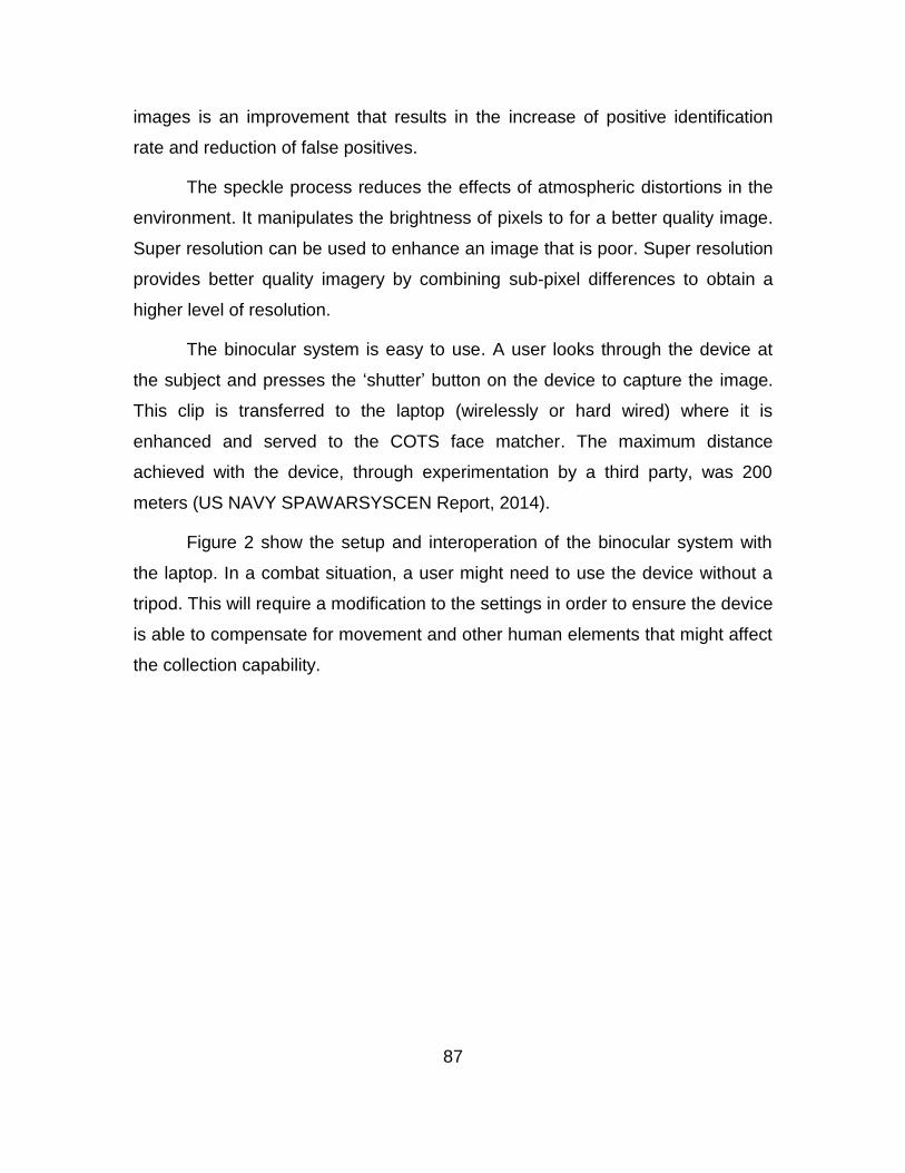
87
images is an improvement that results in the increase of positive identification
rate and reduction of false positives.
The speckle process reduces the effects of atmospheric distortions in the
environment. It manipulates the brightness of pixels to for a better quality image.
Super resolution can be used to enhance an image that is poor. Super resolution
provides better quality imagery by combining sub-pixel differences to obtain a
higher level of resolution.
The binocular system is easy to use. A user looks through the device at
the subject and presses the ‘shutter’ button on the device to capture the image.
This clip is transferred to the laptop (wirelessly or hard wired) where it is
enhanced and served to the COTS face matcher. The maximum distance
achieved with the device, through experimentation by a third party, was 200
meters (US NAVY SPAWARSYSCEN Report, 2014).
Figure 2 show the setup and interoperation of the binocular system with
the laptop. In a combat situation, a user might need to use the device without a
tripod. This will require a modification to the settings in order to ensure the device
is able to compensate for movement and other human elements that might affect
the collection capability.
88
Figure 2. Binocular System Setup and Interoperability
2. System Integration with Laptop
The graphical user interface (GUI) has the capability to communicate
between the laptop and binoculars, enhance captured video and imagery, and
serve to any COTS face matcher with an http interface. The captured video can
be saved and served to the Alarm Center where it can be viewed as well as the
identification results.
The face recognition software has the capability to verify and identify a
subject based on photos contained in the database. Figure 3 and 4 show
verification and identification of a subject.

89
Figure 3. Identification
Figure 4. Verification
The identification image shows the 1:N relationship between the photo
presented and the database queried. The verification image shows the 1:1
relationship between the photo presented and the same image in the database.
The image used in this process was taken with an iPhone and placed in the
“DatabaseImages” file of the program so the 3D Mobile software application can

90
access the image and conduct identification and verification procedures. The
process of placing the photo in this file was part of the instructions listed in the
Manual (US NAVY SPAWARSYSCEN Manual, 2014). Figure 5 is a snapshot of
this process.
Figure 5. Placement of Image for Recognition
C. CONCEPT OF OPERATIONS
The following steps outline the processes and procedures executed during
collection of biometric data at-a-distance. Each step is brief, and, covers
important activities during each process.
1. Setup binoculars/connect to laptop computer
(1) Connect binoculars to 5V battery provided only
(2) Connect binoculars to laptop using the custom USB cord
provided
(3) Mount on tripod for stability
2. Set up laptop computer and binocular applications
(1) Using the laptop, launch Configuration Editor and run the
application as ‘administrator’

91
(2) Select ‘Configuration’ from menu and click ‘Restart
FaceVACs Service’
(3) A green bar = successfully executed
(4) Launch Alert Center Application
(5) Access Facial Database Management
(6) Double-click on ‘Case Management’, click ‘search case’ to
view enrollments
(7) Add/Subtract records to the database
(8) Launch 3DMobileID Application
(9) Configure system to tripod or handheld (pipeline) mode
depending on the setup
(10) While using the application, connect the device by clicking
‘connect’. Once ‘stop’ turns red, press the ‘shutter button’ on
the device to begin recording
3. Execute Facial Recognition
(1) Activate binocular device for recognition
(2) Compare captured data with database images
D. EXPERIMENTATION
While attempting to conduct an experiment with this device, I determined
that it had malfunctioned, and all efforts to execute the process in real time were
deemed impossible. In light of this issue, I focused on the software portion of the
system and used pre-existing video data to develop an understanding of how the
device would work and what steps were taken when accessing real data.
If the device had been operational, it would have produced a 3D video clip
or .vu file, which could be used in the alert system for biometric identification and
verification. Figure 6 provides a snapshot of the files used.
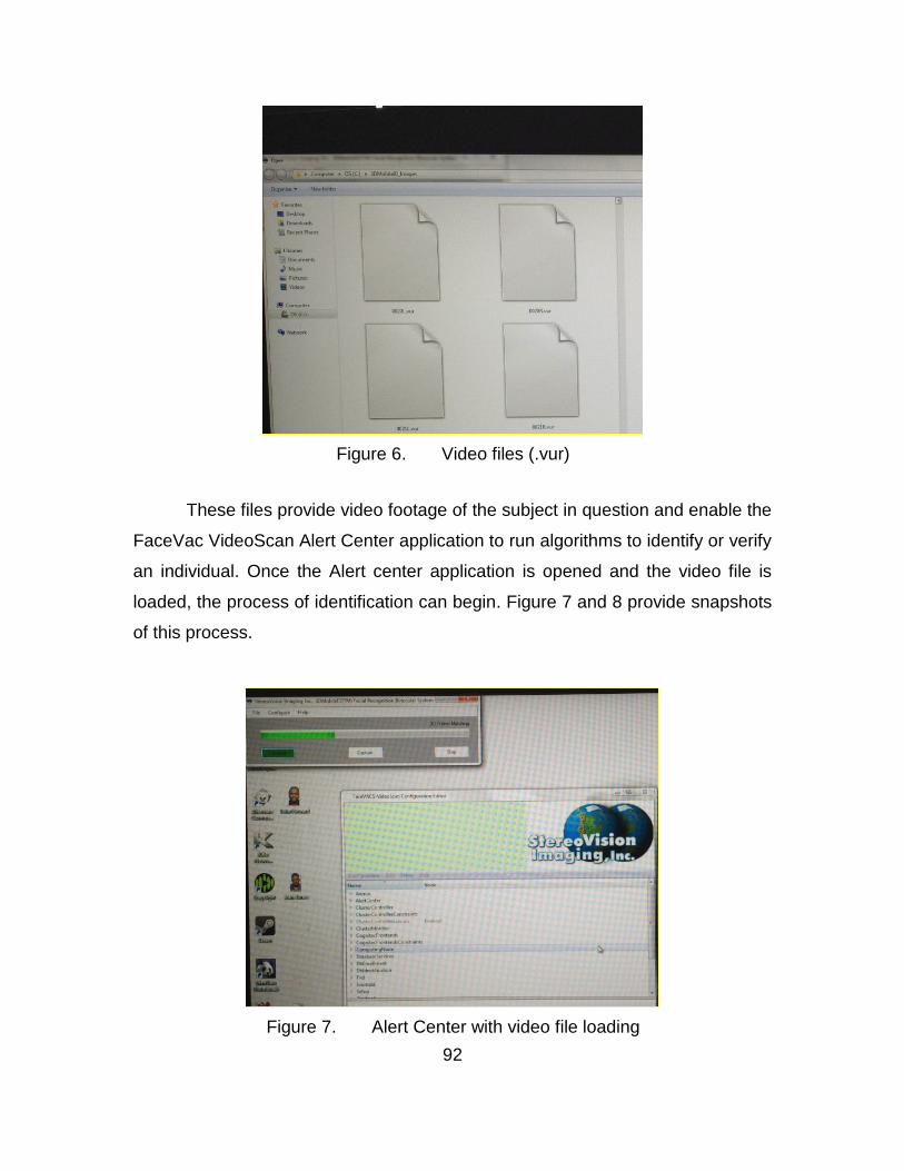
92
Figure 6. Video files (.vur)
These files provide video footage of the subject in question and enable the
FaceVac VideoScan Alert Center application to run algorithms to identify or verify
an individual. Once the Alert center application is opened and the video file is
loaded, the process of identification can begin. Figure 7 and 8 provide snapshots
of this process.
Figure 7. Alert Center with video file loading
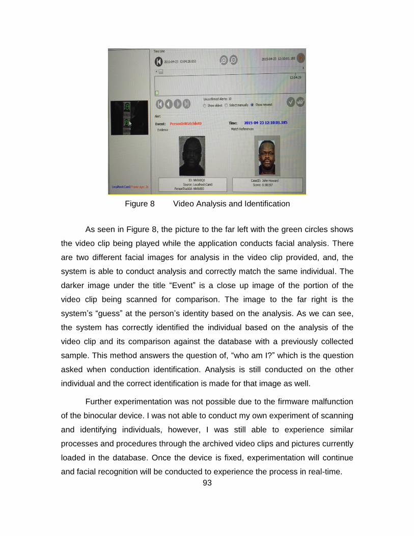
93
Figure 8 Video Analysis and Identification
As seen in Figure 8, the picture to the far left with the green circles shows
the video clip being played while the application conducts facial analysis. There
are two different facial images for analysis in the video clip provided, and, the
system is able to conduct analysis and correctly match the same individual. The
darker image under the title “Event” is a close up image of the portion of the
video clip being scanned for comparison. The image to the far right is the
system’s “guess” at the person’s identity based on the analysis. As we can see,
the system has correctly identified the individual based on the analysis of the
video clip and its comparison against the database with a previously collected
sample. This method answers the question of, “who am I?” which is the question
asked when conduction identification. Analysis is still conducted on the other
individual and the correct identification is made for that image as well.
Further experimentation was not possible due to the firmware malfunction
of the binocular device. I was not able to conduct my own experiment of scanning
and identifying individuals, however, I was still able to experience similar
processes and procedures through the archived video clips and pictures currently
loaded in the database. Once the device is fixed, experimentation will continue
and facial recognition will be conducted to experience the process in real-time.

94
E. SIGNIFICANCE
The significance of this study is to show the capability to collect
physiological biometric data “at-a-distance” in near-real time. This device and the
accompanied software applications provide a capability to enable forces to
collect information on uncooperative subjects, at-a-distance, and, out of sight.
Experimentation with this device will enhance knowledge of tactics, techniques,
and procedures of device employment, and, provide forces with an intelligence-
gathering tool. Through experimentation and enhancement of this device,
deployed forces could receive a combat multiplier in the form of a discreet, at-a-
distance, biometric collection and recognition device, providing relevant
information in a timely manner.
F. CONCLUSION
The 3D Wireless Facial Recognition device shows promise for effective
collection and analysis of biometrics at-a-distance. This capability will give
combat forces an edge in identification of high value targets and enable quick
and effective responses, in near-real time, in any area of operations.
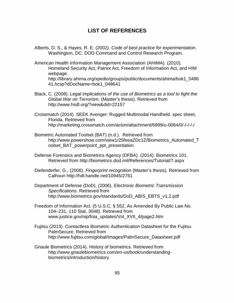
95
LIST OF REFERENCES
Alberts, D. S., & Hayes, R. E. (2002). Code of best practice for experimentation. Washington, DC: DOD Command and Control Research Program.
American Health Information Management Association (AHIMA). (2010). Homeland Security Act, Patriot Act, Freedom of Information Act, and HIM webpage. http://library.ahima.org/xpedio/groups/public/documents/ahima/bok1_048641.hcsp?dDocName=bok1_048641
Black, C. (2008). Legal implications of the use of Biometrics as a tool to fight the Global War on Terrorism. (Master’s thesis). Retrieved from http://www.hsdl.org/?view&did=22157
Crossmatch (2014). SEEK Avenger: Rugged Multimodal Handheld. spec sheet, Florida. Retrieved from http://marketing.crossmatch.com/acton/attachment/6999/u-0064/0/-/-/-/-/
Biometric Automated Toolset (BAT) (n.d.). Retrieved from http://www.powershow.com/view1/25feeaZDc1Z/Biometrics_Automated_Toolset_BAT_powerpoint_ppt_presentation
Defense Forensics and Biometrics Agency (DFBA). (2014). Biometrics 101. Retrieved from http://biometrics.dod.mil/References/Tutorial/7.aspx
Diefenderfer, G., (2006). Fingerprint recognition (Master’s thesis). Retrieved from Calhoun http://hdl.handle.net/10945/2761
Department of Defense (DoD), (2006). Electronic Biometric Transmission Specifications. Retrieved from http://www.biometrics.gov/standards/DoD_ABIS_EBTS_v1.2.pdf
Freedom of Information Act. (5 U.S.C. § 552, As Amended By Public Law No. 104–231, 110 Stat. 3048). Retrieved from www.justice.gov/oip/foia_updates/Vol_XVII_4/page2.htm
Fujitsu (2013). Contactless Biometric Authentication Datasheet for the Fujitsu PalmSecure. Retrieved from http://www.fujitsu.com/global/Images/PalmSecure_Datasheet.pdf
Griaule Biometrics (2014). History of biometrics. Retrieved from http://www.griaulebiometrics.com/en-us/book/understanding-biometrics/introduction/history

96
Homeland Security Act. Public Law 107–296, (2002). Retrieved from www.dhs.gov/xlibrary/assets/hr_5005_enr.pdf
Horton, F.C., III, (2009). Module on the Legal Sources of the Right to Privacy in the context of identity management. Retrieved from http://www.jdsupra.com/post/documentViewer.aspx?fid=c2136cd1-8038-40e3-a788-5c55f2335ad3
Kiefer, J.,& Trissell, K., 2010. DOD Biometrics—Lifting the veil of insurgent identity. Article. Army AL&T. Retrieved at http://asc.army.mil/docs/pubs/alt/2010/2_AprMayJun/articles/14_DOD_Biometrics--Lifting_the_Veil_of_Insurgent_Identity_201002.pdf
Mayhew, S. (2015). History of biometrics. Retrieved from http://www.biometricupdate.com/201501/history-of-biometrics
McKeehan, Z. D. (2008). Vision-based interest point extraction evaluation in multiple environments (Master’s Thesis). Retrieved from Calhoun http://hdl.handle.net/10945/3952
Pato, J. N., & Millett, L. I., National Research Council (U.S.). Whither Biometrics Committee., & ebrary, I. (2010). Biometric recognition: Challenges and opportunities. Retrieved from http://site.ebrary.com/lib/nps/Doc?id=10433656
Patriot Act. Public Law 107–56 (2001). Retrieved from http://frwebgate.access.gpo.gov/cgibin/getdoc.cgi?dbname=107_cong_public_laws&docid=f:publ056.107.pdf
Persistent Systems, (2014). Man Portable Unit Gen 4 spec sheet. Retrieved from http://www.persistentsystems.com/pdf/MPU4_SpecSheet.pdf
Principal Component Analysis. (2015). In Wikipedia. Retrieved from https://en.wikipedia.org/wiki/Principal_component_analysis
Sand, P., Blackburn D., Mortensen, K., Ross, R., Schneider, B., Yonkers, S., & Zok, J., National Science and Technology Council (NSTC), Committee on Technology, Committee on Homeland and National Security, & Subcommittee on Biometrics. (2006). Privacy & biometrics: Building a conceptual foundation. http://www.biometrics.gov/Documents/privacy.pdf
Schulz, R. (2015). Directed Study On 3D Wireless Binocular Facial Recognition System.
Seal, A., Bhattacharjee, D., Nasipuri, M., & Basu, D. K. (2014). Thermal human face recognition for biometric security system. In R. Srivastava, S. Singh, & K. Shukla (Eds.) Research Developments in Biometrics and Video
97
Processing Techniques (pp. 1–24). Hershey, PA: . doi:10.4018/978-1-4666-4868-5.ch001
Sinsel, A., (2015). Supporting The Maritime Information Dominance: Optimizing Tactical Network For Biometric Data Sharing In Maritime Interdiction Operations (Master’s Thesis). Retrieved from Calhoun https://calhoun.nps.edu/bitstream/handle/10945/45257/15Mar_Sinsel_Adam.pdf?sequence=1&isAllowed=y
SVI and SPAWARSYSCEN. (2014a). 3D Wireless Binocular Face Recognition System final report and brief CDRL A004.
SVI and SPAWARSYSCEN. (2014b). 3D Wireless Binocular Facial Recognition System user manual. North Charleston, SC: Author.
Tistarelli, M., Li, S. Z., Chellappa, R. (2009). Handbook of remote biometrics: For surveillance and security. Retrieved from http://libproxy.nps.edu/login?url=http://link.springer.com/book/10.1007/978-1-84882-385-3/page/1
Uniting and Strengthening America by Providing Appropriate Tools Required to Intercept and Obstruct Terrorism (USA Patriot Act) Act of 2001. Public Law 107–56, (2001). Retrieved from http://frwebgate.access.gpo.gov/cgibin/getdoc.cgi?dbname=107_cong_public_laws&docid=f:publ056.107.pdf
U.S. Securities and Exchange Commission (n.d.). Freedom of Information Act Exemptions. Retrieved from www.sec.gov/foia/nfoia.htm
Verret, M, (2006). Performance and usage of biometrics in a testbed environment for tactical purposes (Master’s thesis). Retrieved from Calhoun http://handle.dtic.mil/100.2/ADA462718
Wang, Y. Tan, T., & Jain, A. 2003 Combining Face and Iris Biometrics for Identity Verification. Paper presented at the 4th International Conference, AVBPA 2003, Guildford, UK, June 9–11, 2003, Retrieved from http://link.springer.com/chapter/10.1007%2F3-540-44887-X_93
Yang, F., Paindavoine, M., Abdi., H., & Monopoli, A., 2005. Development of a fast panoramic face mosaicking and recognition system. Optical Engineering Journal (2005) Vol. 44(8) doi:10.1117/1.2009707. Retrieved from http://opticalengineering.spiedigitallibrary.org.libproxy.nps.edu/article.aspx?articleid=1101483

98
THIS PAGE INTENTIONALLY LEFT BLANK

99
INITIAL DISTRIBUTION LIST
1. Defense Technical Information Center Ft. Belvoir, Virginia 2. Dudley Knox Library Naval Postgraduate School Monterey, California