Regional Office Approval ALLIGATOR RIVER NATIONAL WILDLIFE ...

National Technical Approval
Approval No.:
Z-9.1-449
Applicant:SPAX International GmbH & Co.KGKölner Straße 71-7758256 Ennepetal
Approved Product:
SPAX® screwsfor fastening timber
National Technical Approval has herewith been granted for the above named product. This National Technical Approval comprises 13 pages and 17 appendices. This National Technical Approval replaces the National Technical Approval No. Z-9.1-449 da-ted 11th March 2011. The product was first granted National Technical Approval on 2nd March 1999.
Period of validity:from:
to:
1st August 20121st August 2017
Approval body for construction products and const-ruction types
Construction testing institute
A public institution jointly supported by the federal and state governments
Member of EOTA, UEAtc and WFTAO
Date:
31/07/2012
Reference number:
I 56-1.9.1-449#11
Translation of the original German document; translation not examinedby Deutsches Institut für Bautechnik

GENERAL PROVISIONS
The National Technical Approval certifies the suitability and applicability of the productpursuant to the building regulations of the Federal States of Germany.
Wherever demands are placed upon the particular expertise and experience of the persons assigned to undertake the manufacture of construction products and construction types accor-ding to Section 17, Paragraph 5 of the Model Building Regulation respective state rules in the National Technical Approvals, it must be taken into account that this expertise and experience can also be proved by means of equivalent evidence from other member states of the European Union. This may also apply for equivalent evidence presented within the context of the Agree-ment on the European Economic Area (EEA) or other bilateral agreements.
The National Technical Approval shall not exempt the holder from acquiring all approvals, per-missions and certificates legally required for the completion of the relevant building project.
The National Technical Approval is granted without prejudice to the rights of third parties, in particular private property rights.
Irrespective of other regulations laid down in the “Special Regulations”, the manufacturer and distributor of the approved product must forward copies of the National Technical Approval to the user of the approved product and inform him that a copy of the National Technical Approval must be kept available at the location at which the product is used. On request, all authorities involved in the realisation of the construction project must be handed a copy of the National Technical Approval.
The National Technical Approval may only be reproduced in its entirety. The publication of this document is only permitted with the explicit consent of Deutsches Institut für Bautechnik. Texts and graphics in printed promotional material shall not contradict the National Technical Approval. Translations of the National Technical Approval must bear the following notice: “Translation of the original German document; translation not examined by Deutsches Institut für Bautechnik”.
The National Technical Approval can be revoked at any time. The terms and regulations gover-ning National Technical Approvals may be amended, and extended at any time, especially if this is warranted as a result of technological development.
I
1
2
3
4
5
6
7
National Technical ApprovalNo. Z-9.1-449 Page 2 of 12 | 11th March 2011

SPECIAL PROVISIONSII
1
1.1
1.2
Approved Product and Area of Application
Approved Product
Area of Application
The SPAX® screws according to this National Technical Approval are wood connectors with an outer thread diameter of d1 ≥ 8 mm that are manufactured from high-carbon steel or stainless steel. The high-carbon steel screws are equipped with electroplated coatings or with non-electrolytically applied zinc lamellar coatings complete with an additional organic top coat. They serve to connect timber parts manufactured from solid timber and glue-laminated timber, laminated veneer lumber, composite laminated board or composite laminated beam manufac-tured from pine wood, from timber products licensed by a National Technical Approval, or from steel parts to timber parts manufactured from solid timber and glue-laminated timber or from laminated veneer lumber, composite laminated board or composite laminated beam manufac-tured from pine wood licensed by a National Technical Approval.
The SPAX® screws may be used as wood connectors for supporting wood structures that are to be dimensioned and implemented according to standard DIN 10521 unless otherwise stipu-lated in this National Technical Approval.
The dimensioning may also be based on DIN V ENV 1995-1-1:1994-06-Eurocode 5: Design, calculation and dimensioning of timber structures; part 1-1: General dimensioning rules and dimensioning rules for building construction in connection with the national application docu-ment “Guidelines for the application of DIN V ENV 1995-1-1”, February 1995 edition, unless otherwise stipulated.
The screws can be used for joining timber construction components in accordance with Nati-onal Technical Approval if the National Technical Approval granted for the timber component permits the use of screws to this end approved by the general building authority.
The SPAX® screws may not be used for connections to timber products.
However, the timber product boards named below may be connected to timber parts accor-ding to Section 1.1 using the SPAX® screws:
– Plywood according to DIN EN 139862 (DIN EN 6363) and DIN V 20000-14 or according to National Technical Approval
– Synthetic-bonded chipboard according to DIN EN 13986 (DIN EN 3125) and DIN V 2000-1 or according to National Technical Approval
– Type OSB/3 and OSB/4 OSB boards (Oriented Strand Boards) according to DIN EN 13986 (DIN EN 3006) and DIN V 20000-1 or OSB boards according to National Technical Approval
DIN1052:2008-12
DIN EN 13986:2005-03
DIN EN 636:2003-11DIN V 20000-1:2005-12DIN EN 312:2003-11DIN EN 300:2006-09
Design, calculation and dimensioning of timber structures, general dimensioning rules and dimensioning rules for building constructionTimber materials for use in construction – properties, conformity assessment and identificationPlywood specificationsUse of building products in structures – Part 1: timber materialsParticle board specificationsBoards of long, slender, oriented strand board (OSB) – definitions –classification and specifications,
1
2
3
4
5
6
National Technical ApprovalNo. Z-9.1-449 Page 3 of 12 | 11th March 2011
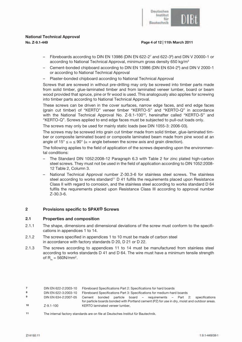
– Fibreboards according to DIN EN 13986 (DIN EN 622-27 and 622-38) and DIN V 20000-1 or according to National Technical Approval, minimum gross density 650 kg/m3
– Cement-bonded chipboard according to DIN EN 13986 (DIN EN 634-29) and DIN V 2000-1 or according to National Technical Approval
– Plaster-bonded chipboard according to National Technical Approval
Screws that are screwed in without pre-drilling may only be screwed into timber parts made from solid timber, glue-laminated timber and from laminated veneer lumber, board or beam wood provided that spruce, pine or fir wood is used. This analogously also applies for screwing into timber parts according to National Technical Approval.
These screws can be driven in the cover surfaces, narrow edge faces, and end edge faces (grain cut timber) of “KERTO” veneer timber “KERTO-S” and “KERTO-Q” in accordance with the National Technical Approval No. Z-9.1-10010, hereinafter called “KERTO-S” and “KERTO-Q”. Screws applied to end edge faces must be subjected to pull-out loads only.
The screws may only be used for mainly static loads (see DIN 1055-3: 2006-03).
The screws may be screwed into grain cut timber made from solid timber, glue-laminated tim-ber or composite laminated board or composite laminated beam made from pine wood at an angle of 15° ≤ a ≤ 90° (a = angle between the screw axis and grain direction).
The following applies to the field of application of the screws depending upon the environmen-tal conditions:
– The Standard DIN 1052:2008-12 Paragraph 6.3 with Table 2 for zinc plated high-carbon steel screws. They must not be used in the field of application according to DIN 1052:2008- 12 Table 2, Column 3.
– National Technical Approval number Z-30.3-6 for stainless steel screws. The stainless steel according to works standard11 D 41 fulfils the requirements placed upon Resistance Class II with regard to corrosion, and the stainless steel according to works standard D 64 fulfils the requirements placed upon Resistance Class III according to approval number Z-30.3-6.
National Technical ApprovalNo. Z-9.1-449 Page 4 of 12 | 11th March 2011
DIN EN 622-2:2003-10DIN EN 622-3:2003-10DIN EN 634-2:2007-05
Z-9.1-100
Fibreboard Specifications Part 2: Specifications for hard boardsFibreboard Specifications Part 3: Specifications for medium-hard boardsCement bonded particle board – requirements – Part 2: specifications for particle boards bonded with Portland cement (PZ) for use in dry, moist and outdoor areas.KERTO laminated veneer lumber,
7
8
9
10
11
2
2.1
Provisions specific to SPAX® Screws
Properties and composition
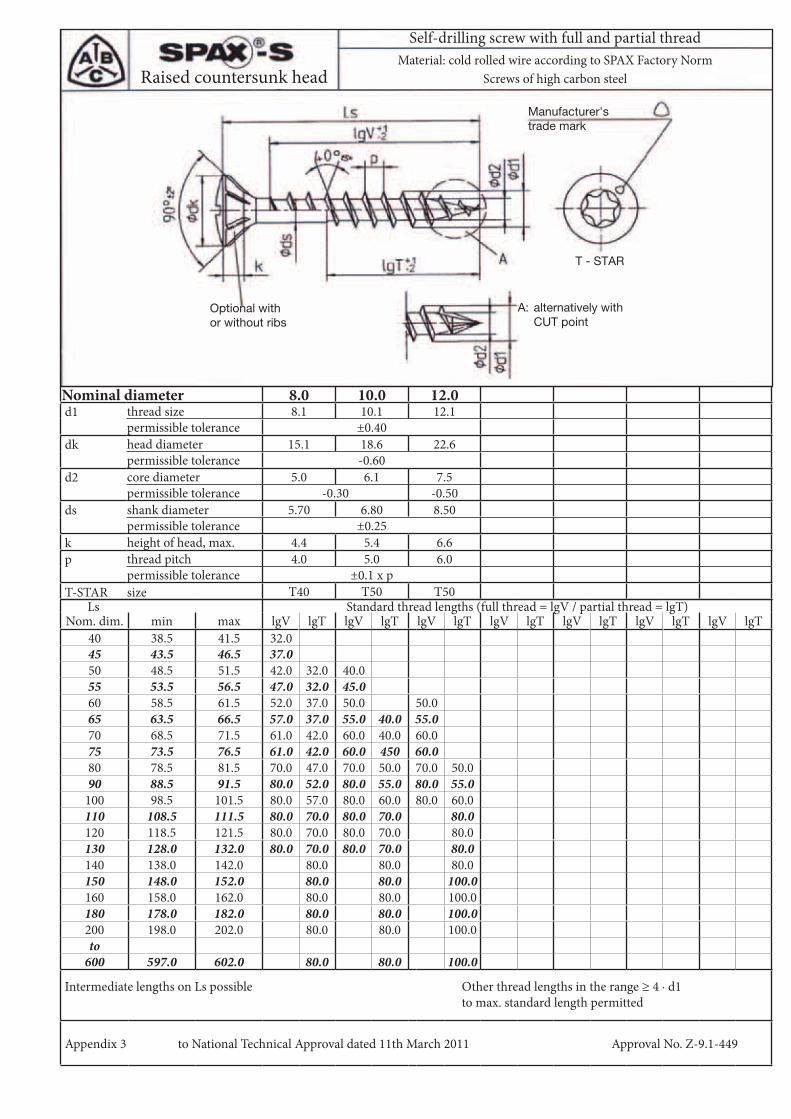
The shape, dimensions and dimensional deviations of the screw must conform to the specifi-cations in appendices 1 to 14.
The screws specified in appendices 1 to 10 must be made of carbon steelin accordance with factory standards D 20, D 21 or D 22.
The screws according to appendices 11 to 14 must be manufactured from stainless steel according to works standards D 41 and D 64. The wire must have a minimum tensile strength of Rm = 560N/mm2.
2.1.1
2.1.2
2.1.3
The internal factory standards are on file at Deutsches Institut für Bautechnik.

National Technical ApprovalNo. Z-9.1-449 Page 5 of 12 | 11th March 2011
The characteristic values of the axial load-bearing capacity Rt,u,k of the screws must not be less than those specified in Table 1.
The characteristic values of the torque at fracture Mt,u,k must not be less than those specified in Table 2.
Table 1: Characteristic values of axial load-bearing capacity Rt,u,k
Table 2: Characteristic values of torque at fracture Mt,u,k
2.1.4
2.1.5
Outer Thread Diameterd1
Characteristic Values of Axial Load-Bearing Capacity Rt,u,k
N
mm High-carbon steel screws Stainless steel screws
8.010.012.0
17,00028,00038,000
12,600--
Outer Thread Diameterd1
Characteristic Values of Torque at Fracture Mt,u,k Nm
mm High-carbon steel screws Stainless steel screws
8.010.012.0
21,00040,00070,000
17,600--
Shape, dimensions and dimensional variations of the washers must correspond to the specifi-cations contained in Appendix 15. The washers must be made of steel.
The screws must be capable of being bent to an angle of 45° without breaking.
2.1.7
2.1.6
2.2
2.3
Identification
Proof of conformity
The packaging of the screws and the manufacturer‘s delivery note must bear the mark of con-formity (Ü mark) in accordance with relevant acts issued by the Federal States. The use of this mark is only permitted if the requirements specified in section 2.3 are met.
The packages and delivery note must also contain the following information:
– Description of the subject of approval (the description „stainless“ is to be entered when dealing with stainless steel screws and the description “SPAX®III Screws” is to be entered when dealing with screws with a particular point shape according to appendices 6 to 10)
– Screw type and screw size
– High-carbon steel screw corrosion protection, where present
– Stainless steel screw corrosion resistance class
General2.3.1
Proof of conformity of the screws with this National Technical Approval must be provided in-dividually for each manufacturing plant and by means of a certificate of conformity based on internal production inspection and regular external production inspection, including an original inspection of the screw in accordance with the provisions below.

National Technical ApprovalNo. Z-9.1-449 Page 6 of 12 | 11th March 2011
For granting the certificate of conformity and the external product inspection, including all necessary products inspections, the manufacturer of the screw must commission an autho-rised certification body as well as an approved inspection body.
The declaration that a certificate of conformity has been issued shall be provided by the ma-nufacturer by labelling the construction product with the mark of conformity whilst stating the intended use.
The certification body must file a copy of the certificate of conformity with Deutsches Institut für Bautechnik.
Internal Production InspectionAn internal production inspection system must be established and operated at each manufac-turing plant. In this context, the internal inspection must provide for the continuous monitoring of production by the manufacturer. The inspection system must ensure that the building pro-ducts manufactured at the relevant plant conform to the specifications laid down in this Natio-nal Technical Approval.
The internal production inspection system must comprise the following procedures as a mini-mum requirement:
– The raw wire must meet the requirements of the works certificate “2.2” according to DIN EN 1020412; compliance with the requirements specified in Section 2.1.2 and 2.1.3 must be checked on the basis of the test certificate
– Testing of the tensile strength and the breaking torque of the screw: One of these tests may be foregone if, in consultation with the inspecting body, the implemented test also allows conclusions to be drawn as regards the adherence of the requirements concerning the untested characteristic.
– 45° bending test
– Inspection of the screw dimensions
All further provisions associated with the internal production inspection system must be set forth in the supervision contract.
The results of the internal production inspection shall be recorded and evaluated. As a mini-mum requirement the records must contain the following details:
– Name of the building product or the raw material and the parts
– Nature of the inspection or testing
– Date of manufacture and inspection of the product or the raw material and the parts
– Results of the tests and inspection and, as far as applicable, a comparison with the specifications
– Signature of person responsible for the internal production inspection
The records must be kept for at least five years, and must be made available to the external in-spection body responsible for the external production control. On request, these records must be made available to Deutsches Institut für Bautechnik an the relevant building supervisory board.
In the event of inadequate test results, the manufacturer is required to take the necessary corrective measures immediately. Non-conforming building products must be identi-fied as such and handled in a way to fully exclude confusion with conforming products. After the situation has been rectified, the relevant test must be repeated without delay to the extent technically feasible and actually required to verify that the non-conformity has been eliminated.
2.3.2
DIN EN 10204:2005-01 Metal Products - Test Certification Methods,12

National Technical ApprovalNo. Z-9.1-449 Page 7 of 12 | 11th March 2011
External Production Inspection
Perpendicular load to the screw axis (shearing)
The in-house production control is to be checked regularly by a third party monitoring at every manufacturer‘s works, at least however once per year.
Within the context of third party monitoring, an initial testing is to be carried out on the screws and samples for random sample testing are to be taken. The sample taking and the testing are the responsibility of the recognised inspecting body respectively. At least the breaking torque, bending angle and the dimensions of the screws are to be tested.
The results of the certification and external production inspection must be kept for at least five years. On request, these records must be made available by the certification body or the autho-rised inspection body to Deutsches Institut für Bautechnik and the relevant building supervisory board.
When dimensioning according to DIN 1052:2008-12 or according to DIN V ENV 1995-1-1:1994-06, the outer thread diameter d1 according to Appendices 1 to 14 may be taken into account as screw diameter d.
2.3.3
3.2.1
3
3.1
3.2
Provisions for design and dimensioning
General
Dimensioning according to DIN 1052:2008-12 or DIN V ENV 1995-1-1 (in combination with the national application document)
For design and dimensioning DIN 1052 applies, unless provided otherwise below. The National Technical Approvals for the timber building components in use are to be adhered to.
Provided the following provisions are adhered to, the dimensions may also be determined in accordance with DIN V ENV 1995-1-1:1994-06 (in conjunction with the National Application Document).
Screw-in depths under 4 · d1 (d1 = outer thread diameter) may not be taken into account.
The calculation value of the slip modulus Kser for the evidence concerning fitness for use of the SPAX® screw with total thread stressed in the axial direction amounts to the following per cutting edge:
Kser = 780 · d10.2 · lef
0.4 (in N/mm) (1)
Wherein:
lef = the respective thread length in both of the individual cross sections in mm
d1 = outer thread diameter of the screw in mm
The calculation value of the slip modulus for proving the load bearing capacity is assumed to be 2/3 of the calculation value of the slip modulus for proving concerning fitness for use.

National Technical ApprovalNo. Z-9.1-449 Page 8 of 12 | 11th March 2011
For the characteristic yield moment values, the values indicated in Table 3 apply.
Table 3: Characteristic Values of Yield Moment My,k
Shearing loads must not be taken into account with regard to screws in front surfaces of “KERTO-S” or “KERTO-Q”.
For screws subject to shear loads driven into the narrow edge faces of “KERTO-Q”, an actual embedding strength of 1/3 of that of the cover surface must be assumed.
When pre-drilling the drill hole for the SPAX® screws, the embediment strength fh,k of the timber materials can be assumed as when dealing with nails in pre-drilled timber parts.
Load in the direction of the screw axisThe characteristic value of the extraction resistance for screws screwed in at an angle of 15° ≤ a ≤ 90° may:
Rax,k = kax · f1,k · lef · d1 (in N) (2)
be taken into account with kax = 0.3 + (0.7 · a)/45° for 15° ≤ a ≤ 45° (3) kax = 1.0 for a ≥ 45° kax = 1.25 for a = 90° and d1 = 8.0 mm for solid timber, glue-laminated timber and composite laminated board or composite laminated beam
a = angle between the screw axis and the grain direction,
15° ≤ a ≤ 90° for solid timber (pine wood), glue-laminated timber (pine wood) and composite laminated board and composite laminated beam
30° ≤ a ≤ 90° for veneer wood with National Technical Approval
f1,k = 80 · 10-6 · k2 (in N/mm2) for solid timber, glue-laminated timber and composite
laminated board or composite laminated beam. (4)
If screws are screwed into the upper surfaces of “KERTO-S” and “KERTO-Q” at an angle of 30° ≤ a ≤ 90°, then f1,k with
f1,k = 70 · 10-6 · k2 (in N/mm2) for d1=8 mm and (5)
f1,k = 80 · 10-6 · k2 (in N/mm2) for d1=8 mm (6)
is to be assumed. These values are to be reduced by 20% where screws are screwed into the edges and front surfaces.
Where:
lef = thread length in the timber section with the screw tip mm. Only the thread length lgV or lgT according to Appendices 1 - 14 may be taken into account as the screw-in depth lef. Screw-in depths lef smaller than 4 · d1 may not be taken into account.
3.2.2
Outer Thread Diameterd1
Characteristic Values of Torque at Fracture Mt,u,k Nm
mm High-carbon steel screws Stainless steel screws
8.010.012.0
20,00030,00048,000
16,700--

National Technical ApprovalNo. Z-9.1-449 Page 9 of 12 | 11th March 2011
d1 = outer thread diameter of the screw in mm
k = characteristic gross density of the timber material in kg/m3
Due to the risk of head pull-through and the risk of the screw threading pull-through through screwed-on timber parts, the characteristic value of the extraction resistance on screws stressed due to extraction may be taken into account with
Wherein:f2,k = characteristic value of the head pull-through parameters in N/mm2 f2,k = 80 · 10-6 · k
2 (8)
For flange head, washer head and pan head screws with flange:
f2,k = 100 · 10-6 · k2 (9)
k = characteristic gross density in kg/m3, maximum 500 kg/m3, maximum 380 kg/m3 for timber boards
dk = head diameter of the screw and the outer diameter of the washer respectively in mm as per appendices 1 to 15. Washer diameters of > 35 mm must not be considered.
lef,k = thread length in timber part to be connected (head-side screw area) in mm
When connecting timber product boards with thicknesses of ≥ 12 to ≤ 20 mm, the characte-ristic value of the head pull-through parameter can be mathematically calculated with
f2,k = 8 N/mm2
The equations (7) and (9) apply to screws with an outer thread diameter of d1 = 12 mm when using wood based panels only together with washers.
When connecting timber product boards, a maximum of 400 N may be taken into account when dealing with board thicknesses of under 12 mm, wherein the minimum thicknesses according to Section 4.4 are to be observed.
Equation (7) is not authoritative with regard to steel plate-wood connections.
The dimensioning value Rt,u,d determined from the characteristic value of the load capability of the screw for tensile load Rt,u,k according to Table 1 may not be exceeded.
3.2.3 Combined load
With regard to connections placed under stress both by impact in the direction of the screw axis (Fax) as well as an impact perpendicular to it (Fla), the following must hold true:
Rax,k = max in N (7)f2,k · dk
2
kax · f1,k · lef,k · d1{
( ) ( )Fax,d Fla,d
Rax,d Rla,d
+ ≤ 1 (10)
2 2
Here, Fax,d and Fla,d are the dimensioning values of the impacts in the direction of / perpendi-cular to the direction of the screw axis and Rax,d and Rla,d are the dimensioning values of the load capabilities of the connections respectively for the case of sole stress in the direction of / perpendicular to the direction of the screw axis.

National Technical ApprovalNo. Z-9.1-449 Page 10 of 12 | 11th March 2011
4
4.1
4.2
4.3
4.4
Provisions for production
For production DIN 1052 applies, unless provided otherwise below. The National Technical Approvals for timber building components are to be observed.
The screws may only be used for the fastening of solid timber parts (soft wood) and elements made of glue-laminated timber, laminated veneer according to the National Technical Approval and and wood based panels in accordance with Section 3.1, or for fastening steel parts to so-lid timber parts (soft wood), and elements made of glue-laminated timber or laminated veneer according to the National Technical Approval.
This National Technical Approval does not apply to connections to particle boards including OSB boards, fibre boards or plywood panels. For fastening in solid timber, glue-laminated tim-ber, laminated veneer lumber, the screws may only be used for products made of spruce, pine or spruce fir. This applies also to the use of screws for fastening timber construction compo-nents in accordance with National Technical Approval.
Screws with an outer thread diameter of d1 ≥ 8 mm that are screwed in without pre-drilling may only be screwed into timber parts made from solid timber, glue-laminated timber and from laminated veneer lumber, composite laminated board or composite laminated beam provided that spruce, pine or fir wood is used. This analogously also applies to screwing into timber parts according to the National Technical Approval.
These screws may be driven into the cover surfaces, narrow edge faces, and end edge faces of “KERTO” veneer timber “KERTO-S” and “KERTO-Q” in accordance with the National Technical Approval No. Z-9.1-100, hereinafter called “KERTO-S” and “KERTO-Q”. Screws applied to end edge faces must be subjected to pull-out loads only.
The screws may only be driven with the tools recommended for that purpose by the manufacturer.
When pre-drilling the timber part for the SPAX® screws, the diameter of the drill hole is to be selected such that it conforms to the core diameter d2 of the SPAX® screws.
The holes in steel components are to be pre-drilled with a suitable diameter. In cement-bonded particle boards, the screw holes must be predrilled with a diameter of 0.7 · d1. In timber building components the screws must be driven without pre-drilling.
The screw thread may also be in the fastened timber component.
The screws must be countersunk into the timber construction components such that the screw head is flush with the surface of the fastened part, but for washer head, pan head and hex head with head part k protruding. Deeper countersinking is not permitted.
The countersunk screws may be used together with washers in accordance with appendix 15. The full surface of the washer must rest against the timber when the screw has been driven. High-carbon steel countersunk screws may only be used with high-carbon steel washers and stainless steel screws may only be used with stainless steel washers.
When dealing with SPAX® screws with an outer thread diameter of d1 = 8 mm, that will be screwed into timber parts that have not been pre-drilled, the thickness of the timber parts to be connected must measure at least 30 mm, when dealing with screws with d1 = 10 mm, the thickness must measure at least 40 mm and when dealing with screws with d1 = 12 mm, the thickness must measure at least 80 mm.
When connecting timber boards to timber parts according to Section 1.1 using SPAX® screws, their board thickness must measure at least 1.2 · d1 (d1 = outer thread diameter of the screw).
+ 0.0 mm- 0.5 mm

National Technical ApprovalNo. Z-9.1-449 Page 11 of 12 | 11th March 2011
4.6 Minimum distances4.6.1
4.6.1.1
4.5.
4.6.1.2
4.6.1.3
4.6.2
Perpendicular load to the screw axis (shearing)
Timber parts that have not been pre-drilled
The values according to DIN 1052 must be adhered to as minimum distances of the screws when dealing with timber parts regulated by the standard, as with nails with pre-drilled nail holes, wherein the outer thread diameter d1 according to appendices 1 to 14 is to be considered as the screw diameter.
The distance of the screws from the edge in the grain direction must amount to at least 15 · d1.
The values according to DIN 1052 must be adhered to as minimum distances of the SPAX® screws with CUT point or 4CUT point when dealing with timber parts regulated by the standard, as with nails with pre-drilled nail holes. The minimum distance a1 parallel to the grain direction must not be lower than 5 · d1 and the minimum distance to the end grain a3,c or a3,t must not be lower than 12 · d1. The named minimum distances only apply under the prerequisite that a mi-nimum wood cross section of 40 · d1
2 and a minimum thickness of the timber parts of 7 · d1 are adhered to. If the minimum wood cross section of 40 · d1
2 is not reached, the values according to DIN 1052 shall be adhered to as minimum distances for the screws when dealing with tim-ber parts regulated by the standard, as with nails with nail holes that have not been pre-drilled.
When dealing with SPAX® screws without CUT point or 4CUT point that have to be screwed into timber parts that have not been pre-drilled, and if the distance to each other in the grain direction and to the end grain measures at least 25 · d1 then the distance to the unstressed edge may be reduced to 3 · d1 perpendicular to the grain direction.
When dealing with Douglas-fir, the minimum distances in the grain direction are to be increased by 50%.
For end grain connections solid timber must be at least half-cut and the timber moisture content must not exceed 18% at the time of fastening.
Pre-drilled timber parts
For minimum distances in timber construction components in accordance with the National Technical Approval, the provisions of the National Technical Approvals apply.Load in the direction of the screw axis
When dealing with screws that are planned to be exclusively stressed in the direction of the screw axis with an outer thread diameter of d1 = 8 mm or with CUT point or 4CUT point, the following minimum distances may be used as a basis when dealing with timber parts that have not been pre-drilled (see Appendices 16 and 17):
Distance a1 between the screw axes in a plane parallel to grain direction: a1 = 5 · d1
Distance a2 between the screw axes at right angles to a plane parallel to grain direction: a2 = 5 · d1
The values according to DIN 1052 must be adhered to as minimum distances of the SPAX® screws in pre-drilled timber parts when dealing with timber parts regulated by the standard, as with nails with pre-drilled nail holes.
Furthermore, the board thickness must be not less than
6 mm for plywood and fibreboard, not less than
8 mm for synthetic-bonded chipboard, OSB boards and not less than
10 mm for plaster-bonded chipboard.
The regulations of the National Technical Approvals apply with regard to the minimum thicknes-ses of timber parts according to National Technical Approvals.

National Technical ApprovalNo. Z-9.1-449 Page 12 of 12 | 11th March 2011
4.6.3
Distance a3,c between the centre of gravity of the portion of the screw in the timber and the end grain face: a3,c = 5 · d1
Distance a4,c between the centre of gravity of the portion of the screw in the timber and the side face: a4,c = 4 · d1
For screws with CUT point or 4CUT point: a4,c = 3 · d1
The distance a2 between the screw axes may be reduced to 2.5 · d1, provided each screw has a connecting face of a1 · a2 = 25 · d1
2. The distances also apply when screwing into pre-drilled timber parts.
For screws that crossover, the axis distance a2 can be assumed as shown below:
Minimum distances for connections using “KERTO-S” and “KERTO-Q”.For connections with “KERTO-Q” (narrow edge faces ) and “KERTO-S” subject to shear loads, the minimum distances laid down in DIN 1052 must be complied with; the same applies to nails without pre-drilling. The screw diameter d1 is calculated as the outer thread diameter as spe-cified in the Appendices 1 to 14.
For the distances of screws driven into the cover surfaces of “KERTO-Q” the values in Table 5 of the National Technical Approval No. Z-9.1-100 dated 26/05/2006 apply.
For screws which, according to the construction design, are subject to loads in screw axis direction exclusively and are driven into “KERTO-Q” or “KERTO-S” with a minimum thickness of t = 6 · d1, the following minimum distances apply (see Appendices 16 to 17):
Distance a1 between the screw axes in a plane parallel to grain direction: a1 = 5 · d1
Distance a2 between the screw axes at right angles to a plane parallel to grain direction: a2 = 5 · d1
Distance a3,c between the centre of gravity of the portion of the screw in the timber and the end grain face: a3,c = 5 · d1
Distance a4,c between the centre of gravity of the portion of the screw in the timber and the side face: a4,c = 3 · d1
The distance a2 between the screw axes may be reduced to 2.5 · d1, provided each screw has a connecting face of a1 · a2 = 25 · d1
2
For screws that crossover, the axis distance a2 according to Equation (11) can be assumed.
Minimum distances a1 and a2 are to be observed between the screws arranged in parallel belonging to adjacent screw intersections.
Rainer SchäpelHead of Division
a2 = max (11){ 1.5 · d1 for 70° < ak ≤ 90° 2.5 · d1 1- for 0° < ak ≤ 70°
ak180°( )
ak See Appendix 17 for crossing angle of the screws
Minimum distances a1 and a2 are to be observed between screws arranged in parallel belonging to adjacent screw intersections.

Nominal diameter 8.0 10.0 12.0d1 thread size 8.1 10.1 12.1
permissible tolerance ±0.40dk head diameter 15.1 18.6 22.6
permissible tolerance -0.60d2 core diameter 5.0 6.1 7.5
permissible tolerance -0.30 -0.50ds shank diameter 5.70 6.80 8.50
permissible tolerance ±0.25k height of head, max. 4.4 5.4 6.6p thread pitch 4.0 5.0 6.0
permissible tolerance ±0.1 x pT-STAR size T40 T50 T50
Ls Standard thread lengths (full thread = lgV / partial thread = lgT)Nom. dim. min max lgV lgT lgV lgT lgV lgT
40 38.5 41.5 32.045 43.5 46.5 37.050 48.5 51.5 42.0 32.0 40.055 53.5 56.5 47.0 32.0 45.060 58.5 61.5 52.0 37.0 50.0 50.065 63.5 66.5 57.0 37.0 55.0 40.0 55.070 68.5 71.5 61.0 42.0 60.0 40.0 60.075 73.5 76.5 61.0 42.0 60.0 450 60.080 78.5 81.5 70.0 47.0 70.0 50.0 70.0 50.090 88.5 91.5 80.0 52.0 80.0 55.0 80.0 55.0100 98.5 101.5 80.0 57.0 80.0 60.0 80.0 60.0110 108.5 111.5 80.0 70.0 80.0 70.0 80.0120 118.5 121.5 80.0 70.0 80.0 70.0 80.0130 128.0 132.0 80.0 70.0 80.0 70.0 80.0140 138.0 142.0 80.0 80.0 80.0150 148.0 152.0 80.0 80.0 100.0160 158.0 162.0 80.0 80.0 100.0180 178.0 182.0 80.0 80.0 100.0200 198.0 202.0 80.0 80.0 100.0to600 597.0 602.0 80.0 80.0 100.0
Intermediate lengths on Ls possible Other thread lengths in the range ≥ 4 · d1 to max. standard length permitted
Appendix 1 to National Technical Approval dated 11th March 2011 Approval No. Z-9.1-449
Self-drilling screw with full and partial threadMaterial: cold rolled wire according to SPAX Factory Norm
Screws of high carbon steel
Optional with andwithout ribs
A: alternatively with CUT point
T - STAR
Countersunk head
Manufacturer's trade mark

Nominal diameter 8.0 10.0 12.0d1 thread size 8.1 10.1 12.1
permissible tolerance ±0.40dk head diameter 18.0 21.0 23.0 26.0 31.0
permissible tolerance ±1.5dk1 countersink diameter 9.0 12.0 14.0
permissible tolerance +0.30d2 core diameter 5.0 6.1 7.5
permissible tolerance -0.30 -0.5ds shank diameter 5.70 6.80 8.50
permissible tolerance ±0.25k height of head, max. 4.0 4.7 5.6p thread pitch 4.0 5.0 6.0
permissible tolerance ±0.1 x pT-STAR size T40 T50
Ls Standard thread lengths (full thread = lgV / partial thread = lgT)Nom. dim. min max lgV lgT lgV lgT lgV lgT
40 38.5 41.5 37.045 43.5 46.5 42.050 48.5 51.5 46.0 32.055 53.5 56.5 51.0 32.0 50.0 50.060 58.5 61.5 56.0 37.0 55.0 55.065 63.5 66.5 61.0 37.0 60.0 40.0 60.070 68.5 71.5 61.0 42.0 60.0 40.0 60.075 73.5 76.5 70.0 42.0 70.0 45.0 70.080 78.5 81.5 70.0 47.0 70.0 50.0 70.0 50.090 88.5 91.5 80.0 52.0 80.0 55.0 80.0 55.0100 98.5 101.5 80.0 57.0 80.0 60.0 80.0 60.0110 108.5 111.5 80.0 70.0 80.0 70.0 80.0120 118.5 121.5 80.0 70.0 80.0 70.0 80.0130 128.0 132.0 80.0 70.0 80.0 70.0 80.0140 138.0 142.0 80.0 80.0 80.0150 148.0 152.0 80.0 80.0 100.0160 158.0 162.0 80.0 80.0 100.0180 178.0 182.0 80.0 80.0 100.0200 198.0 202.0 80.0 80.0 100.0to600 597.0 602.0 80.0 80.0 100.0
Intermediate lengths on Ls possible Other thread lengths in the range ≥ 4 · d1to max. standard length permitted
Appendix 2 to National Technical Approval dated 11th March 2011 Approval No. Z-9.1-449
Self-drilling screw with full and partial threadMaterial: cold rolled wire according to SPAX Factory Norm
Screws of high carbon steel
A: alternatively with CUT point
T - STAR
Washer head
Manufacturer's trade mark
Nominal diameter 8.0 10.0 12.0d1 thread size 8.1 10.1 12.1
permissible tolerance ±0.40dk head diameter 15.1 18.6 22.6
permissible tolerance -0.60d2 core diameter 5.0 6.1 7.5
permissible tolerance -0.30 -0.50ds shank diameter 5.70 6.80 8.50
permissible tolerance ±0.25k height of head, max. 4.4 5.4 6.6p thread pitch 4.0 5.0 6.0
permissible tolerance ±0.1 x pT-STAR size T40 T50 T50
Ls Standard thread lengths (full thread = lgV / partial thread = lgT)Nom. dim. min max lgV lgT lgV lgT lgV lgT lgV lgT lgV lgT lgV lgT lgV lgT
40 38.5 41.5 32.045 43.5 46.5 37.050 48.5 51.5 42.0 32.0 40.055 53.5 56.5 47.0 32.0 45.060 58.5 61.5 52.0 37.0 50.0 50.065 63.5 66.5 57.0 37.0 55.0 40.0 55.070 68.5 71.5 61.0 42.0 60.0 40.0 60.075 73.5 76.5 61.0 42.0 60.0 450 60.080 78.5 81.5 70.0 47.0 70.0 50.0 70.0 50.090 88.5 91.5 80.0 52.0 80.0 55.0 80.0 55.0100 98.5 101.5 80.0 57.0 80.0 60.0 80.0 60.0110 108.5 111.5 80.0 70.0 80.0 70.0 80.0120 118.5 121.5 80.0 70.0 80.0 70.0 80.0130 128.0 132.0 80.0 70.0 80.0 70.0 80.0140 138.0 142.0 80.0 80.0 80.0150 148.0 152.0 80.0 80.0 100.0160 158.0 162.0 80.0 80.0 100.0180 178.0 182.0 80.0 80.0 100.0200 198.0 202.0 80.0 80.0 100.0to600 597.0 602.0 80.0 80.0 100.0
Intermediate lengths on Ls possible Other thread lengths in the range ≥ 4 · d1 to max. standard length permitted
Appendix 3 to National Technical Approval dated 11th March 2011 Approval No. Z-9.1-449
Self-drilling screw with full and partial threadMaterial: cold rolled wire according to SPAX Factory Norm
Screws of high carbon steel
Optional withor without ribs
T - STAR
Raised countersunk head
A: alternatively with CUT point
Manufacturer's trade mark

Nominal diameter 8.0 10.0 12.0d1 thread size 8.1 10.1 12.1
permissible tolerance ±0.40dk head diameter 15.5 19.0 23.0
permissible tolerance -0.60d2 core diameter 5.0 6.1 7.5
permissible tolerance -0.30 -0.50ds shank diameter 5.70 6.80 8.50
permissible tolerance ±0.25k height of head, max. 5.7 7.1 8.5R pan radius approx. 16.0 20.0 24.0p thread pitch 4.0 5.0 6.0
permissible tolerance ±0.1 x pT-STAR size T40 T50 T50
Ls Standard thread lengths (full thread = lgV / partial thread = lgT)Nom. dim. min max lgV lgT lgV lgT lgV lgT
40 38.5 41.5 37.045 43.5 46.5 42.050 48.5 51.5 46.0 32.055 53.5 56.5 51.0 32.0 50.0 50.060 58.5 61.5 56.0 37.0 55.0 55.065 63.5 66.5 61.0 37.0 60.0 40.0 60.070 68.5 71.5 61.0 42.0 60.0 40.0 60.075 73.5 76.5 70.0 42.0 70.0 45.0 70.080 78.5 81.5 70.0 47.0 70.0 50.0 70.0 50.090 88.5 91.5 80.0 52.0 80.0 55.0 80.0 55.0100 98.5 101.5 80.0 57.0 80.0 60.0 80.0 60.0110 108.5 111.5 80.0 70.0 80.0 70.0 80.0120 118.5 121.5 80.0 70.0 80.0 70.0 80.0130 128.0 132.0 80.0 70.0 80.0 70.0 80.0140 138.0 142.0 80.0 80.0 80.0150 148.0 152.0 80.0 80.0 100.0160 158.0 162.0 80.0 80.0 100.0180 178.0 182.0 80.0 80.0 100.0200 198.0 202.0 80.0 80.0 100.0to600 597.0 602.0 80.0 80.0 100.0
Intermediate lengths on Ls possible Other thread lengths in the range ≥ 4 · d1 to max. standard length permitted
Appendix 4 to National Technical Approval dated 11th March 2011 Approval No. Z-9.1-449
Self-drilling screw with full and partial threadMaterial: cold rolled wire according to SPAX Factory Norm
Screws of high carbon steel
T - STAR
Pan head
A: alternatively with CUT point
Manufacturer's trade mark

with flange no flangeNominal diameter 8.0 10.0 12.0 8.0 10.0 12.0d1 thread size 8.1 10.1 12.1 8.1 10.1 12.1
permissible tolerance ±0.40 ±0.40SW width across flat 10 13 16 10 13 16Dc flange diameter 17.0 20.8 24.7
permissible tolerance -1.00d2 core diameter 5.0 6.1 7.5 5.0 6.1 7.5
permissible tolerance -0.30 -0.50 -0.30 -0.50ds shank diameter 5.70 6.80 8.50 5.70 6.80 8.50
permissible tolerance ±0.25 ±0.25k height of head, max. 8.5 9.7 12.1 6.0 7.0 8.0p thread pitch 4.0 5.0 6.0 4.0 5.0 6.0
permissible tolerance ±0.1 x p ±0.1 x pLs Standard thread lengths (full thread = lgV / partial thread = lgT)
Nom. dim. min max lgV lgT lgV lgT lgV lgT lgV lgT lgV lgT lgV lgT40 38.5 41.5 37.0 37.045 43.5 46.5 42.0 42.050 48.5 51.5 46.0 32.0 45.0 46.0 32.0 45.055 53.5 56.5 51.0 32.0 50.0 50.0 51.0 32.0 50.0 50.060 58.5 61.5 56.0 37.0 55.0 55.0 56.0 37.0 55.0 55.065 63.5 66.5 61.0 37.0 60.0 40.0 60.0 61.0 37.0 60.0 40.0 60.070 68.5 71.5 61.0 42.0 60.0 40.0 60.0 61.0 42.0 60.0 40.0 60.075 73.5 76.5 70.0 42.0 70.0 45.0 70.0 70.0 42.0 70.0 45.0 70.080 78.5 81.5 70.0 47.0 70.0 50.0 70.0 50.0 70.0 47.0 70.0 50.0 70.0 50.090 88.5 91.5 80.0 52.0 80.0 55.0 80.0 55.0 80.0 52.0 80.0 55.0 80.0 55.0100 98.5 101.5 80.0 57.0 80.0 60.0 80.0 60.0 80.0 57.0 80.0 60.0 80.0 60.0110 108.5 111.5 80.0 70.0 80.0 70.0 80.0 80.0 70.0 80.0 70.0 80.0120 118.5 121.5 80.0 70.0 80.0 70.0 80.0 80.0 70.0 80.0 70.0 80.0130 128.0 132.0 80.0 70.0 80.0 70.0 80.0 80.0 70.0 80.0 70.0 80.0140 138.0 142.0 80.0 80.0 80.0 80.0 80.0 80.0150 148.0 152.0 80.0 80.0 100.0 80.0 80.0 100.0160 158.0 162.0 80.0 80.0 100.0 80.0 80.0 100.0180 178.0 182.0 80.0 80.0 100.0 80.0 80.0 100.0200 198.0 202.0 80.0 80.0 100.0 80.0 80.0 100.0to600 597.0 602.0 80.0 80.0 100.0 80.0 80.0 100.0
Intermediate lengths on Ls possible Other thread lengths in the range ≥ 4 · d1 to max. standard length permitted
Appendix 5 to National Technical Approval dated 11th March 2011 Approval No. Z-9.1-449
Self-drilling screw with full and partial threadMaterial: cold rolled wire according to SPAX Factory Norm
Screws of high carbon steel
A: alternatively with CUT point
Hex. headwith flange
Hex. head
Hex. head with/without flange
Manufacturer's trade mark

Nominal diameter 8.0d1 thread size 8.1
permissible tolerance ±0.40dk head diameter 15.1
permissible tolerance -0.60d2 core diameter 5.0
permissible tolerance ±0.20ds shank diameter 5.70
permissible tolerance ±0.25k height of head, max. 4.4p thread pitch 4.8
permissible tolerance ±0.1 x pT-STAR plus size T40
Ls Standard thread lengths (full thread = lgV / partial thread = lgT)Nom. dim. min max lgV lgT
40 38.5 41.5 32.045 43.5 46.5 37.050 48.5 51.5 42.0 32.055 53.5 56.5 47.0 32.060 58.5 61.5 52.0 37.065 63.5 66.5 57.0 37.070 68.5 71.5 61.0 42.075 73.5 76.5 61.0 42.080 78.5 81.5 70.0 47.090 88.5 91.5 80.0 52.0100 98.5 101.5 80.0 57.0110 108.5 111.5 80.0 70.0120 118.5 121.5 80.0 70.0130 128.0 132.0 80.0 70.0140 138.0 142.0 80.0150 148.0 152.0 80.0160 158.0 162.0 80.0180 178.0 182.0 80.0200 198.0 202.0 80.0to600 597.0 602.0 80.0
Intermediate lengths on Ls possible Other thread lengths in the range ≥ 4 · d1 to max. standard length permitted
Appendix 6 to National Technical Approval dated 11th March 2011 Approval No. Z-9.1-449
Self-drilling screw with full and partial threadMaterial: cold rolled wire according to SPAX Factory Norm
Screws of high carbon steel
Manufacturer‘s trade mark
“SPAX”
C: alternative with 4CUT cutter available D: 4CUT point
T - STARplus
Optional with or without ribs
Countersunk head
4CUT point:Square point
in core
Cross section A-B
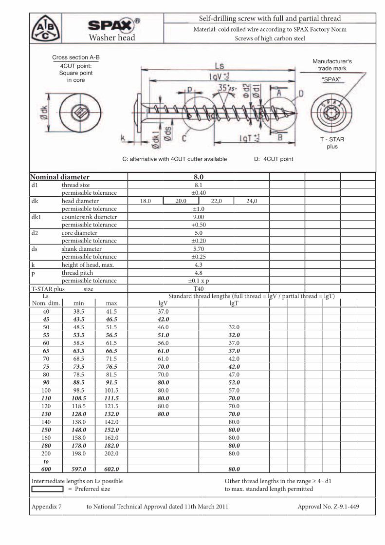
Nominal diameter 8.0d1 thread size 8.1
permissible tolerance ±0.40dk head diameter 18.0 20.0 22,0 24,0
permissible tolerance ±1.0dk1 countersink diameter 9.00
permissible tolerance +0.50d2 core diameter 5.0
permissible tolerance ±0.20ds shank diameter 5.70
permissible tolerance ±0.25k height of head, max. 4.3p thread pitch 4.8
permissible tolerance ±0.1 x p T-STAR plus size T40
Ls Standard thread lengths (full thread = lgV / partial thread = lgT)Nom. dim. min max lgV lgT
40 38.5 41.5 37.045 43.5 46.5 42.050 48.5 51.5 46.0 32.055 53.5 56.5 51.0 32.060 58.5 61.5 56.0 37.065 63.5 66.5 61.0 37.070 68.5 71.5 61.0 42.075 73.5 76.5 70.0 42.080 78.5 81.5 70.0 47.090 88.5 91.5 80.0 52.0100 98.5 101.5 80.0 57.0110 108.5 111.5 80.0 70.0120 118.5 121.5 80.0 70.0130 128.0 132.0 80.0 70.0140 138.0 142.0 80.0150 148.0 152.0 80.0160 158.0 162.0 80.0180 178.0 182.0 80.0200 198.0 202.0 80.0to600 597.0 602.0 80.0
Intermediate lengths on Ls possible = Preferred size
Other thread lengths in the range ≥ 4 · d1 to max. standard length permitted
Appendix 7 to National Technical Approval dated 11th March 2011 Approval No. Z-9.1-449
Self-drilling screw with full and partial threadMaterial: cold rolled wire according to SPAX Factory Norm
Screws of high carbon steel
“SPAX”
C: alternative with 4CUT cutter available D: 4CUT point
T - STARplus
Washer head
4CUT point:Square point
in core
Cross section A-BManufacturer‘s
trade mark

Nominal diameter 8.0d1 thread size 8.1
permissible tolerance ±0.40dk head diameter 15.1
permissible tolerance -0.60d2 core diameter 5.0
permissible tolerance ±0.20ds shank diameter 5.70
permissible tolerance ±0.25k height of head, max. 4.4p thread pitch 4.8
permissible tolerance ±0.1 x pT-STAR plus size T40
Ls Standard thread lengths (full thread = lgV / partial thread = lgT)Nom. dim. min max lgV lgT
40 38.5 41.5 32.045 43.5 46.5 37.050 48.5 51.5 42.0 32.055 53.5 56.5 47.0 32.060 58.5 61.5 52.0 37.065 63.5 66.5 57.0 37.070 68.5 71.5 61.0 42.075 73.5 76.5 61.0 42.080 78.5 81.5 70.0 47.090 88.5 91.5 80.0 52.0100 98.5 101.5 80.0 57.0110 108.5 111.5 80.0 70.0120 118.5 121.5 80.0 70.0130 128.0 132.0 80.0 70.0140 138.0 142.0 80.0150 148.0 152.0 80.0160 158.0 162.0 80.0180 178.0 182.0 80.0200 198.0 202.0 80.0to600 597.0 602.0 80.0
Intermediate lengths on Ls possible Other thread lengths in the range ≥ 4 · d1 to max. standard length permitted
Appendix 8 to National Technical Approval dated 11th March 2011 Approval No. Z-9.1-449
Self-drilling screw with full and partial threadMaterial: cold rolled wire according to SPAX Factory Norm
Screws of high carbon steel
“SPAX”
C: alternative with 4CUT cutter available D: 4CUT point
T - STARplus
Optional with or without ribs
Raised countersunk head
4CUT point:Square point
in core
Cross section A-B Manufacturer‘s trade mark

Nominal diameter 8.0d1 thread size 8.1
permissible tolerance ±0.40dk head diameter 15.5
permissible tolerance -0.60d2 core diameter 5.0
permissible tolerance ±0.20ds shank diameter 5.70
permissible tolerance ±0.25k height of head, max. 6.0p thread pitch 4.8
permissible tolerance ±0.1 x pT-STAR plus size T40
Ls Standard thread lengths (full thread = lgV / partial thread = lgT)Nom. dim. min max lgV lgT
40 38.5 41.5 37.045 43.5 46.5 42.050 48.5 51.5 46.0 32.055 53.5 56.5 51.0 32.060 58.5 61.5 56.0 37.065 63.5 66.5 61.0 37.070 68.5 71.5 61.0 42.075 73.5 76.5 70.0 42.080 78.5 81.5 70.0 47.090 88.5 91.5 80.0 52.0100 98.5 101.5 80.0 57.0110 108.5 111.5 80.0 70.0120 118.5 121.5 80.0 70.0130 128.0 132.0 80.0 70.0140 138.0 142.0 80.0150 148.0 152.0 80.0160 158.0 162.0 80.0180 178.0 182.0 80.0200 198.0 202.0 80.0to600 597.0 602.0 80.0
Intermediate lengths on Ls possible Other thread lengths in the range ≥ 4 · d1 to max. standard length permitted
Appendix 9 to National Technical Approval dated 11th March 2011 Approval No. Z-9.1-449
Self-drilling screw with full and partial thread
Pan headMaterial: cold rolled wire according to SPAX Factory Norm
Screws of high carbon steel
“SPAX”
C: alternative with 4CUT cutter available D: 4CUT point
T - STARplus
4CUT point:Square point
in core
Cross section A-B Manufacturer‘s trade mark

with flange no flangeNominal diameter 8.0 8.0d1 thread size 8.1 8.1
permissible tolerance ±0.40 ±0.40dk width across flat 10 10Dc flange diameter 17.0 -
permissible tolerance -1.00 -d2 core diameter 5.0 5.0
permissible tolerance ±0.20 ±0.20ds shank diameter 5.70 5.70
permissible tolerance ±0.25 ±0.25k height of head, max. 4.4 4.4p thread pitch 4.8 4.8
permissible tolerance ±0.1 x p ±0.1 x pLs Standard thread lengths (full thread = lgV / partial thread = lgT)
Nom. dim. min max lgV lgT40 38.5 41.5 32.0 32.045 43.5 46.5 37.0 37.050 48.5 51.5 42.0 32.0 42.0 32.055 53.5 56.5 47.0 32.0 47.0 32.060 58.5 61.5 52.0 37.0 52.0 37.065 63.5 66.5 57.0 37.0 57.0 37.070 68.5 71.5 61.0 42.0 61.0 42.075 73.5 76.5 61.0 42.0 61.0 42.080 78.5 81.5 70.0 47.0 70.0 47.090 88.5 91.5 80.0 52.0 80.0 52.0100 98.5 101.5 80.0 57.0 80.0 57.0110 108.5 111.5 80.0 70.0 80.0 70.0120 118.5 121.5 80.0 70.0 80.0 70.0130 128.0 132.0 80.0 70.0 80.0 70.0140 138.0 142.0 80.0 80.0150 148.0 152.0 80.0 80.0160 158.0 162.0 80.0 80.0180 178.0 182.0 80.0 80.0200 198.0 202.0 80.0 80.0to600 597.0 602.0 80.0 80.0
Intermediate lengths on Ls possible Other thread lengths in the range ≥ 4 · d1 to max. standard length permitted
Appendix 10 to National Technical Approval dated 11th March 2011 Approval No. Z-9.1-449
Self-drilling screw with full and partial thread
Hex. head with/without flangeMaterial: cold rolled wire according to SPAX Factory Norm
Screws of high carbon steel
“SPAX”
Hex. headwith flange
C: alternative with 4CUT cutter available D: 4CUT point
Hex. head
Manufacturer's trade mark
4CUT point:Square point in core
Cross section A-B

Nominal diameter 8.0d1 thread size 8.1
permissible tolerance ±0.40dk head diameter 15.1
permissible tolerance -0.60d2 core diameter 5.3
permissible tolerance ±0.20ds shank diameter 5.70
permissible tolerance ±0.25k height of head, max. 4.4p thread pitch 4.8
permissible tolerance ±0.1 x pT-STAR plus size T40
Ls Standard thread lengths (full thread = lgV / partial thread = lgT)Nom. dim. min max lgV lgT
40 38.5 41.5 32.045 43.5 46.5 37.050 48.5 51.5 42.0 32.055 53.5 56.5 47.0 32.060 58.5 61.5 52.0 37.065 63.5 66.5 57.0 37.070 68.5 71.5 61.0 42.075 73.5 76.5 61.0 42.080 78.5 81.5 70.0 47.090 88.5 91.5 80.0 52.0100 98.5 101.5 80.0 57.0110 108.5 111.5 80.0 70.0120 118.5 121.5 80.0 70.0130 128.0 132.0 80.0 70.0140 138.0 142.0 80.0150 148.0 152.0 80.0160 158.0 162.0 80.0
Intermediate lengths on Ls possible Other thread lengths in the range ≥ 4 · d1 to max. standard length permitted
Appendix 11 to National Technical Approval dated 11th March 2011 Approval No. Z-9.1-449
Self-drilling screw with full and partial thread
Countersunk headMaterial: cold rolled wire according to SPAX Factory Norm
Stainless steel screws
“SPAX”
T - STARplus
4CUT point:Square point
in core
Cross section A-B
C: alternative with 4CUT cutter available D: 4CUT pointOptional with or without ribs
Manufacturer‘s trade mark

Nominal diameter 8.0d1 thread size 8.1
permissible tolerance ±0.40dk head diameter 18.0 20.0 22.0 24.0
permissible tolerance ±1.0dk1 countersink diameter 9.00
permissible tolerance +0.50d2 core diameter 5.3
permissible tolerance ±0.20ds shank diameter 5.70
permissible tolerance ±0.25k height of head, max. 4.3p thread pitch 4.8
permissible tolerance ±0.1 x p T-STAR plus size T40
Ls Standard thread lengths (full thread = lgV / partial thread = lgT)Nom. dim. min max lgV lgT lgV lgT lgV lgT lgV lgT
40 38.5 41.5 37.045 43.5 46.5 42.050 48.5 51.5 46.0 32.055 53.5 56.5 51.0 32.060 58.5 61.5 56.0 37.065 63.5 66.5 61.0 37.070 68.5 71.5 61.0 42.075 73.5 76.5 70.0 42.080 78.5 81.5 70.0 47.090 88.5 91.5 80.0 52.0100 98.5 101.5 80.0 57.0110 108.5 111.5 80.0 70.0120 118.5 121.5 80.0 70.0130 128.0 132.0 80.0 70.0140 138.0 142.0 80.0150 148.0 152.0 80.0160 158.0 162.0 80.0
Intermediate lengths on Ls possible = Preferred size
Other thread lengths in the range ≥ 4 · d1 to max. standard length permitted
Appendix 12 to National Technical Approval dated 11th March 2011 Approval No. Z-9.1-449
Self-drilling screw with full and partial thread
Washer headMaterial: cold rolled wire according to SPAX Factory Norm
Stainless steel screws
“SPAX”
C: alternative with 4CUT cutter available D: 4CUT point
T - STARplus
4CUT point:Square point
in core
Cross section A-BManufacturer‘s
trade mark

Nominal diameter 8.0d1 thread size 8.1
permissible tolerance ±0.40dk head diameter 15.1
permissible tolerance -0.60d2 core diameter 5.3
permissible tolerance ±0.20ds shank diameter 5.70
permissible tolerance ±0.25k height of head, max. 4.4p thread pitch 4.8
permissible tolerance ±0.1 x pT-STAR plus size T40
Ls Standard thread lengths (full thread = lgV / partial thread = lgT)Nom. dim. min max lgV lgT
40 38.5 41.5 32.045 43.5 46.5 37.050 48.5 51.5 42.0 32.055 53.5 56.5 47.0 32.060 58.5 61.5 52.0 37.065 63.5 66.5 57.0 37.070 68.5 71.5 61.0 42.075 73.5 76.5 61.0 42.080 78.5 81.5 70.0 47.090 88.5 91.5 80.0 52.0100 98.5 101.5 80.0 57.0110 108.5 111.5 80.0 70.0120 118.5 121.5 80.0 70.0130 128.0 132.0 80.0 70.0140 138.0 142.0 80.0150 148.0 152.0 80.0160 158.0 162.0 80.0
Intermediate lengths on Ls possible Other thread lengths in the range ≥ 4 · d1 to max. standard length permitted
Appendix 13 to National Technical Approval dated 11th March 2011 Approval No. Z-9.1-449
Self-drilling screw with full and partial thread
Raised countersunk headMaterial: cold rolled wire according to SPAX Factory Norm
Stainless steel screws
“SPAX”
C: alternative with 4CUT cutter available D: 4CUT point
T - STARplus
Manufacturer‘s trade mark4CUT point:
Square pointin core
Cross section A-B
Optional with or without ribs

Nominal diameter 8.0d1 thread size 8.1
permissible tolerance ±0.40dk head diameter 15.5
permissible tolerance -0.60d2 core diameter 5.3
permissible tolerance ±0.20ds shank diameter 5.70
permissible tolerance ±0.25k height of head, max. 6.0p thread pitch 4.8
permissible tolerance ±0.1 x pT-STAR plus size T40
Ls Standard thread lengths (full thread = lgV / partial thread = lgT)Nom. dim. min max lgV lgT
40 38.5 41.5 37.045 43.5 46.5 42.050 48.5 51.5 47.0 32.055 53.5 56.5 52.0 32.060 58.5 61.5 57.0 37.065 63.5 66.5 61.0 37.070 68.5 71.5 61.0 42.075 73.5 76.5 70.0 42.080 78.5 81.5 70.0 47.090 88.5 91.5 80.0 52.0100 98.5 101.5 80.0 57.0110 108.5 111.5 80.0 70.0120 118.5 121.5 80.0 70.0130 128.0 132.0 80.0 70.0140 138.0 142.0 80.0150 148.0 152.0 80.0160 158.0 162.0 80.0
Intermediate lengths on Ls possible Other thread lengths in the range ≥ 4 · d1 to max. standard length permitted
Appendix 14 to National Technical Approval dated 11th March 2011 Approval No. Z-9.1-449
Self-drilling screw with full and partial thread
Pan headMaterial: cold rolled wire according to SPAX Factory Norm
Stainless steel screws
“SPAX”
C: alternative with 4CUT cutter available D: 4CUT point
T - STARplus
4CUT point:Square point
in core
Cross section A-B Manufacturer‘s trade mark

Thread size 6.0 8.0 10.0 12.0 Tolerance
ØDa 18.0 25.0 32.0 40.0
± 0.3ØDi 6.5 8.5 11.0 13.0ØD1 13.5 17.5 22.5 27.0ØD2 12.5 16.5 21.5 26.0 t 3.5 5.0 5.6 7.0
Appendix 15 to National Technical Approval dated 11th March 2011 Approval No. Z-9.1-449
Washer for screws with countersunk and raised countersunk head
WasherMaterial: Free cutting or stainless steel
Dimensions in mm

a1 = 5 · d1 a3,c = 5 · d1
a2 = 2.5 · d1
a4,c = 4 · d1a4,c = 3 · d1 for CUT or 4CUT point
a1 · a2 = 25 · d12
Minimum distances for screws with d1 ≤ 8 mm or with CUT or 4CUT point, planned to be exclusively stressed in the shaft direction.
Parallel arrangement (example for 3 pairs of screws)
Top view
Side view
direction of grain screw axis
Tim
ber
thi
ckne
ss≥
12
· d1
Com
pon
ent
wid
thcentre of gravity of the embedded portion of the screw
The stipulations in Section 4.6 of the approval apply to KERTO-S and KERTO-Q.
Appendix 16 to National Technical Approval dated 11th March 2011 Approval No. Z-9.1-449

a1 = 5 · d1 a3,c = 5 · d1
a2 = max a4,c = 4 · d1
a4,c = 3 · d1 for CUT or 4CUT point
a1 · a2 = 25 · d12
Crosswise arrangement (example for 1 pair of screws)
direction of grain screw axis
centre of gravity of the embedded portion of the screw
The stipulations in Section 4.6 of the approval apply to KERTO-S and KERTO-Q.
1.5 · d1 70° < ak ≤ 90°
2.5 · d1 30° ≤ ak ≤ 70°{ 1- ak
180( )
Appendix 17 to National Technical Approval dated 11th March 2011 Approval No. Z-9.1-449
Top view
Side view
Minimum distances for screws with d1 ≤ 8 mm or with CUT or 4CUT point, planned to be exclusively stressed in the shaft direction.
Tim
ber
thi
ckne
ss≥
12
· d1
Com
pon
ent
wid
th