National Subsea Research Initiative - Championing the UK ...€¦ · National Subsea Research...
19
www.nsri.co.uk National Subsea Research Initiative An introduction to NSRI February 2015 Gordon Drummond; Project Director, NSRI
Transcript of National Subsea Research Initiative - Championing the UK ...€¦ · National Subsea Research...

www.nsri.co.uk
National Subsea Research Initiative
An introduction to NSRI
February 2015
Gordon Drummond; Project Director, NSRI

www.nsri.co.uk
Overview
• Who we are & Why we do it.
• What we do & How we do it.
• Product life cycle
• NSRI in action

www.nsri.co.uk
Who we are
A “not for profit”, industry led & expertly guided organisation
To enhance the UK’s position as the leading technology provider for the
subsea industry
• Technology Arm of Subsea UK
• A Board and Steering Group membership comprising of industry leading figures

www.nsri.co.uk
Why we do it
Ref: Subsea UK; 2013
Subsea sector growth
• Worth nearly £9 Billion; 43% in exports
• Exports are configured
• 50 : 50 Products & Services
• Industry forecasted for strong growth
• However under threat...

www.nsri.co.uk
Overview
• Who we are & Why we do it.
• What we do & How we do it.
• NSRI website
• Product life cycle
• NSRI in action

www.nsri.co.uk
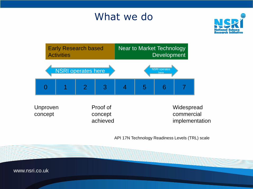
What we do
Industrial Need
(End user)
Suppliers Offering
Academic Capability
Marry Need to Ambition & Capability
www.nsri.co.uk
What we do
4
Unproven
concept
Proof of
concept
achieved
Widespread
commercial
implementation
NSRI operates here
API 17N Technology Readiness Levels (TRL) scale
3210 5 6 7
NSRI operates
here
Early Research based
Activities
Near to Market Technology
Development

www.nsri.co.uk
How we do it
Suppliers and Academic
capability and expertise
Potential Solutions
End user specific challenges
End user drivers New challenging environment
Deep location
High strength steels
Uni. Manchester
materials research
Exova
Test facilities
Tata
steel

www.nsri.co.uk
How we do it

www.nsri.co.uk
How we do it - STAGs and themes
Technology Priority Industry Challenge STAG(s)
Reduce Exploration Costs:
Challenging Environments
Peter Blake / Paul Charlton
Internationalisation Peter Blake / Paul Charlton
Increase Efficiency: Simulation & Modelling Jason Tisdall
Work methods Neil Gordon
Small field / cluster dev. Gordon Drummond
Reduce Operational Costs:
Hardware- SPS Paul White
Hardware- SURF Gordon Drummond
Operational Controls Peter Blake
Life of field Assurance Jason Tisdall
Economic Appraisals Paul Charlton
Increase Productivity: EOR / IOR Peter Blake
Well Intervention Paul White
Reduce Decommissioning Costs:
Paul Charlton

www.nsri.co.uk
R&D Themes
from
Leadership
BoardsTLB, OGUK ILB, etc
Proposals from
IndustrySubsea Community
Technology
gapsIndustry STeering
Advisory Group (STAG)
Routes to
R&D fundingInterface, OGIC, ITF,
Innovate, RCUK, etc
Collaborative Project Team
FormedSome or all of: Customer; Supplier; Academia; Test facility;
Ind. 3rd party Qualification body
R&D Project Definition
In-house
development
Proposals from
AcademiaAcademic Community
R&D Project Execution In-field useInputs
Widespread
Commercial
Implementation
Progression through
TRL scale

www.nsri.co.uk
Overview
• Who we are & Why we do it.
• What we do & How we do it.
• Product life cycle
• NSRI in action

www.nsri.co.uk
Technology Readiness Levels (TRLs) – Product life Cycle
43210 5 6 7
12 – 16 yrs
www.nsri.co.uk
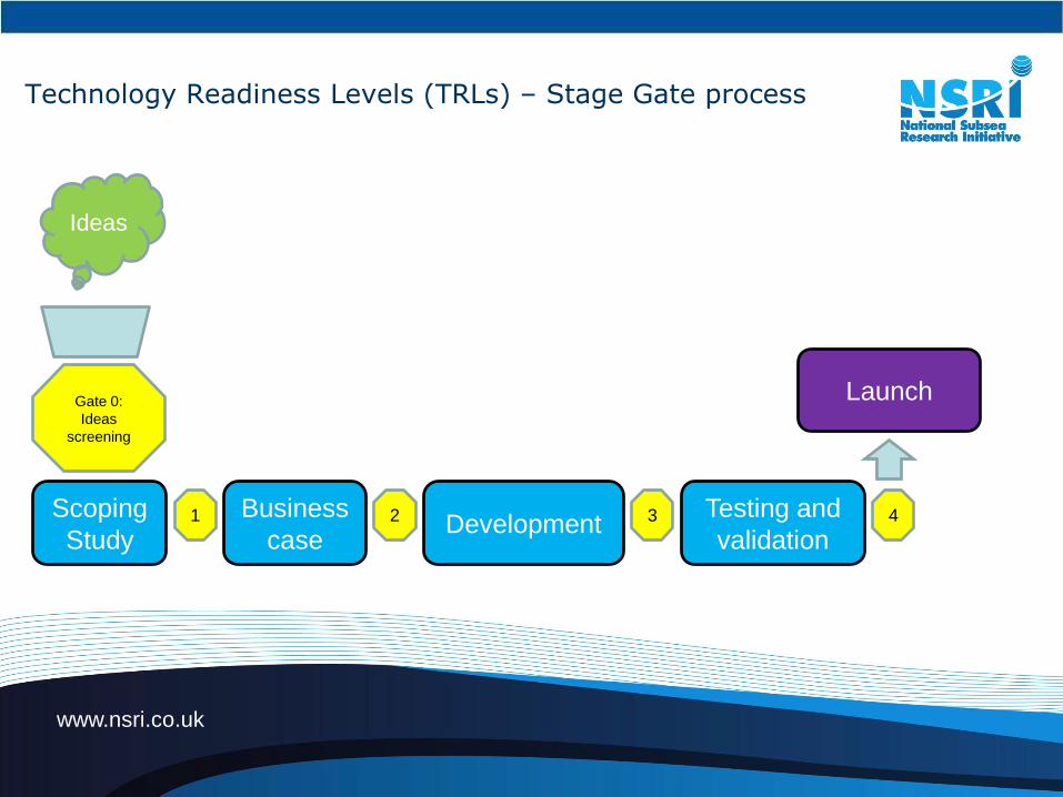
Technology Readiness Levels (TRLs) – Stage Gate process
Ideas
Scoping
Study
Gate 0:
Ideas
screening
1 Business
caseDevelopment
Testing and
validation2 3 4
Launch

www.nsri.co.uk
How we do it:
-Standardisation of language and qualification process
- Use of TRLS
-Qualification dossier
0 1 2 3 4 5 6 7
Unproven Concept Conceptually Proven Validated Concept Prototype Tested Environment Tested System Tested System Installed Field Poven
A solution to a technical challenge
has been conceived
Desktop and analytical studies
confirm feasiblity and a suite of
tests are devised to validate the
concept
Experiments / Benchtesting performed to
achieve Proof of Concept. The overarching
plan is developed and is underway
A fully functional prototype has been
developed and tested, the generic solution
is accepted as being "qualified" for use.
A demonstrator is designed and
constructed to meet specific project
environmental conditions and subjected to
test in that environment.
The demonstrator is refined to integrate
with other systems and the interfaces
tested . Ancillary details are completed to
"go live".
System piloted in final environment Operating as intended.
Academic environment Desktop environment Controlled laboratory environment Controlled laboratory environment Realistic environment outside the lab, but
not the eventual operating environment
Operational environment, but not on the
eventual platform
All functionality demonstrated in simulated
operational environmenet
Operational Concept has been
implemented successfully in field
• Basic scientific principles observed
• Have some concept in mind that may be
feasible
• Know what challenge needs to overcome in
general terms
• Potential solution(s) have been identified
• Paper studies confirm basic principles
• Research hypothesis formulated
• The basic components of a solution have
been identified
• Preliminary analysis (Desktop) used to
verify solution
• Individual components work, but no real
attempt at integration
• Know what experiments need to be
performed to validate (research approach)
• Interface effects (if any) have begun to be
identified
• Experiments carried out with representative data sets
• Laboratory experiments verify feasibility
• Rigorous analytical studies confirm basic principles
• Analysis provides detailed knowledge of how specific
components need to perform
• Experiments with individual components show that
they work together
• Some ad hoc integration of components demonstrate
that they will work together
• Stand-alone components identified in preliminary
system
• Requirements for each function established
• Interface issues (if any) have been fully identified
• Development of the components that make up the
system begins
• Basic Functionality demonstrated in simplified
environment
• Scientific feasibility fully demonstrated
• Interface effects (if any) identified and are being
addressed
• Architecture established
• Construction of individual components completed
• Components integrated into subsystems and
function tested
• Scaling trials performed
• Integration of sub-systems demonstrated in a
laboratory environment - Lab based Prototype System
• Systems debugged
• Prototype tested with generalised characteristics
representative of target environment
• Generic Solution qualified
• Specific operating environment for eventual system
defined
• Lab based Prototype system designed and
constructed as a Demonstrator to meet specific
environment
• Factory acceptance testing of Demonstrator system
in laboratory setting
• Demonstrator tested in simulated operational
environment
• Engineering feasibility fully demonstrated
• Each system interface tested individually under
stressed and anomalous conditions
• Components are representative of in service /as built
• Fully integrated solution demonstrated in actual or
simulated operational environment
• Solution successfully qualified for specific field
application
• Components are form, fit, and function compatible
with operational system
• System fully qualified through test and evaluation in
actual environment
• System has been installed and deployed in
operational environment and is performing as intended
• Actual system fully demonstrated
• Know who cares about technology, e.g.,
sponsor, money source
• Know who will perform research and where
it will be done
• Architecture defined in terms of major
packages identified
• Know capabilities and limitations of
researchers and research facilities
• Qualitative idea of risk areas (cost,
schedule, performance)
• Risk areas identified in general terms
• Clearly defined scope
• Risk mitigation strategies identified
• Success Metrics established
• Intellectual property protection approach
considered
• Functional work breakdown structure developed
• Able to estimate fully estimate the program size in
terms of duration, cost and work packages
• Integrated Project Team (IPT) established
• System performance metrics have been established
• Formal risk management program initiated
• Preliminary Failure Mode and Effects Analysis
(FMEA) or Risk analysis performed
• Technology availability dates established
• System requirements flow down through work
breakdown structure (systems engineering begins)
• Physical work breakdown structure available
• Management plan in place
• Design techniques have been defined to the point
where largest problems are defined
• Risk management plan documented
"Alpha" version has been released "Beta" version has been released
• Most documentation completed and under revidsion
control.
• Most training documentation completed and under
review control.
• Safety/Adverse effects issues have been identified
and mitigated.
• Training Plan has been implemented.
• Intellectual Property Protection has been completed.
• Paper studies show that application is
feasible
• Customer/end user identified
• Know where the technology will be applied
• Customer/end user expresses interest in
application
• Have rough idea of how to market
technology (Who's interested, how will they
find out about it?)
• Customer/end user representative
identified to work with development team
• Customer/end user participates in
requirements generation
• Customer/end user identifies window(s) of
opportunity for implementation
• Know what technology is presently available
that does similar task
• Analysis of present state of the art shows
that technology fills a need
• Know limitations of presently available
technology
• Customer/end user publishes requirements
document
• Overall system requirements for end user's
application are known
• Form, fit, and function for application addressed in
conjunction with end user
• Customer/end user commits to implementation plan
Implementation planning has been reviewed by end
user and developer
• Formal inspection included for all
modules/components
• Quality and reliability considered, but target levels not
yet established
• Draft Inspection and Test Plan (ITP)
• 3rd Party Verification considered
• Quality and reliability levels established
• Collection of actual quality data has been started• Quality data is being analysed Quality data meets targets All processes controlled to appropriate quality level
Initial scientific observations reported in
journals/conference proceedings/technical
reports
• Analytical studies reported in scientific
journals/conference proceedings/technical
reports
• Paper studies indicate that system
components ought to work together
• Draft Project Execution Plan (PEP)
compiled
• Draft conceptual solutions have been documented
• Draft Project Execution Plan (PEP) revised to include
experimentation
• Prelimary Project Execution Plan (PEP) revised to
address wider implementation
• Prelimary Project Execution Plan (PEP) revised to
address business case
• Detailed design drawings have been completed
• Significant engineering and design changes
• Project Execution Plan (PEP) compiled / completion
• Final Technical Report
• Frequent design changes occur
Marketing material compiled Training documentation compiled
• All documentation completed
• Design stable, few or no design changes
Co
mm
erc
ial
Ma
turi
tyQ
ua
lity
Ma
turi
tyD
oc
um
en
tati
on
Ma
turi
ty
Environmen
t
TECHNOLOGY MATURITY ASSESSMENT GRID
1 Line
Description
Te
ch
no
log
y M
atu
rity
Pro
jec
t M
an
ag
em
en
t M
atu
rity
Level

www.nsri.co.uk
Overview
• Who we are & Why we do it.
• What we do & How we do it.
• Product life cycle
• NSRI in action

www.nsri.co.uk
NSRI in action
Tasked by the UK O&G Technology Leadership Board to coordinate the research theme:
“Exploitation of small pools”
Image courtesy of Subsea 7

www.nsri.co.uk
Overview
• Who we are & Why we do it.
• What we do & How we do it.
• Product life cycle
• NSRI in action

www.nsri.co.uk
www.nsri.co.uk
NSRI- the focal point for Subsea Research and Development activity in the UK
This is the source of useful information
Thanks to our sponsors:BP
ShellSubsea 7
Subsea UK Scottish Enterprise
Thank you for you attention