NATIONAL STANDARDS COMMISSION · NATIONAL STANDARDS COMMISSION ... Acme (Lubricating Oil) ... is...
18
NATIONAL STANDARDS COMMISSION WEIGHTS 6 MEASURES (PATTERNS OF INSTRUMENTS) REGULATIONS REGULATION 9 CERTIFICATE Ok APPROVAL No 5/6D/29 This is to certify that an approval has been granted by the Commission that the pattern and variants of the Acme (Lubricating Oil) Flowmeter With Neptune 38 mm Type 4 Meter submitted by Acme Oil Equipment Services Pty Ltd 253 Ingles Street Port Melbourne, Victoria, 3207 are suitable for use for trade. The approval is subject to review on or after l/7/81. Instruments purporting to comply with this approval shall be marked with NSC No 5/6D/29. Relevant drawings and specifications are lodged with the Comnission. Conditions of Approval 1. The flow rate is limited to between 10 L/min and 100 L/min. 2. The maximum system pressure is 500 kPa. 3. The pump suction operates under a positive liquid head. 4. The viscosity of the liquid to be measured lies in the range 100 mPa.s to 1000 mPa.S for 0 temperaturerange of 5’C to 40°C. 5. The type of liquid for which the instrument is verified is marked on the instrument &ta plote. Signed "I .f . --h Execu ive Director Descriptive Advice Pattern: approved 2516176 . Acme (lubricating oil) flowmeter with Neptune 38 nmn type 4 meter and Nep- tune type 442 indicator ond set stop counter. Variants: approved 2516176 1. With Neptune type 441 indicator. 2. With Neptune type 443 indicator and ticket printer. 3. With Neptune type 444 indicator, ticket printer ond set stop counter. Technical Schedule No 5/6D/29 doted 29/10/76 describes the pattern and variants 1 to 3. 2817 2182 . . . ..I2
Transcript of NATIONAL STANDARDS COMMISSION · NATIONAL STANDARDS COMMISSION ... Acme (Lubricating Oil) ... is...

NATIONAL STANDARDS COMMISSION
WEIGHTS 6 MEASURES (PATTERNS OF INSTRUMENTS) REGULATIONS
REGULATION 9
CERTIFICATE Ok APPROVAL No 5/6D/29
This is to certify that an approval has been granted by the Commission that the pattern and variants of the
Acme (Lubricating Oil) Flowmeter With Neptune 38 mm Type 4 Meter
submitted by Acme Oil Equipment Services Pty Ltd 253 Ingles Street Port Melbourne, Victoria, 3207
are suitable for use for trade.
The approval is subject to review on or after l/7/81.
Instruments purporting to comply with this approval shall be marked with NSC No 5/6D/29.
Relevant drawings and specifications are lodged with the Comnission.
Conditions of Approval
1. The flow rate is limited to between 10 L/min and 100 L/min.
2. The maximum system pressure is 500 kPa.
3. The pump suction operates under a positive liquid head.
4. The viscosity of the liquid to be measured lies in the range 100 mPa.s to 1000 mPa.S for 0 temperature range of 5’C to 40°C.
5. The type of liquid for which the instrument is verified is marked on the instrument &ta plote.
Signed
"I
.f
.
--h
Execu ive Director
Descriptive Advice
Pattern: approved 2516176
. Acme (lubricating oil) flowmeter with Neptune 38 nmn type 4 meter and Nep- tune type 442 indicator ond set stop counter.
Variants: approved 2516176
1. With Neptune type 441 indicator.
2. With Neptune type 443 indicator and ticket printer.
3. With Neptune type 444 indicator, ticket printer ond set stop counter.
Technical Schedule No 5/6D/29 doted 29/10/76 describes the pattern and variants 1 to 3.
2817 2182 . . . ..I2

Certificate of Approval No 5/6D/29 Page 2
Variant: opproved 14/l 2176
4. With any type, bore or length of hose,
Technical Schedule No 5/6D/29 Voriotion No 1 doted 27/l/77 describes variant 4.
Voriont: approved 3/l 2182
5. With on internal float volve which replaces the low level cut-off system fitted to the pattern.
Technical Schedule No 5/6D/29 Voriotion No 2 doted 28112182 describes variant 5.
Filing Advice
Certificate of Approvol No 5/6D/29 doted 27/l/77 is superseded by this Certificate and may be destroyed. The documentation for this opprovol now comprises:
Certificate of Approvol No 5/6D/29 &ted 28112182 Technical Schedule No 5/6D/29 doted 29110176 (including Special Tests) Technic01 Schedule No 5/6D/29 Voriotion No 1 doted 27/l/77 (including Table 1) Technical Schedule No 5160129 Voriotion No 2 doted 28112182 Test Procedure No 5/6D/29 Voriotion No 2 doted 28/12/82 Figures 1 to 7 doted 29110176 Figure 8 doted 28/12/82.
28/l 2182
- NATIONAL STANDARDS COMMISSION
TECHNICAL SCHEDULE No 5/6D/29
Pattern: Acme (Lubricating Oil) Flowmeter with Neptune 38-mm
Type 4 Meter
Submittor: Acme Oil Equipment Services Pty Ltd, 253 Ingles Street, Port Melbourne, Victoria, 3207.
Date of Approval: 25 June 1976
Conditions of Approval:
1. The flow rate is limited to between 10 and 100 litres per minute.
2. The maximum system pressure is 500 kPa.
3. The pump suction operates under a positive liquid head.
4. The viscosity of the liquid to.be measured lies in the range 100 to 1000 mPa.s for a temperature range of 5OC to 40°C.
5. The liquid (commercial or technical name) for which the instrument is verified is nominated on the instrument data plate.
All instruments conforming to this approval shall be marked "NSC No 5/6D/29".
Description:
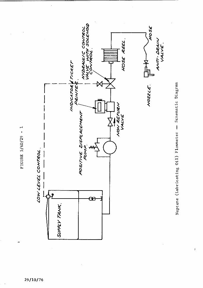
The pattern (see Figure 1) is a vehicle-mounted instrument for the
delivery of liquid petroleum of viscosity between 100 and 1000 mPa.s at a flow rate between 10 and 100 litres per minute and at a maximum system pressure of 500 kPa.
The flowmeter comprises the following:
1. Mowbrey low-level float switch in the supply tank which ensures that the delivery stops before the liquid level falls low enough to allow air to enter the system (see Figure 1).
2. Positive displacement pump mounted on the assembly at a point lower than the minimum height of the liquid in the supply tank.
29/10/76 . ../2
Technical Schedule No 5/6D/29 Page 2
3. Non-return valve located between the pump and meter, or between
the meter and the hose.
4. Neptune 38-mm Type 4 meter (see Figure 2).
5. Neptune Type 442 zero-start indicator and set-stop counter (see Figure 2). The indicator has a scale interval of 1 litre; ' the first element is marked with ten scale-mark lines numbered from 0 to 9. The aperture through which the first element is viewed is widened in the direction of travel.
6. Neptune outlet-control valve (see Figure 2).
7. Hydraulically operated shut-off valve with electrical solenoid control, which stops a delivery when the level of liquid in the supply tank is below the set minimum, the supply of electrical power fails, or the diaphragm in the valve ruptures (see Figure
3).
8. Hose - up to 20 metres of 32-mm bore Nylex hose.
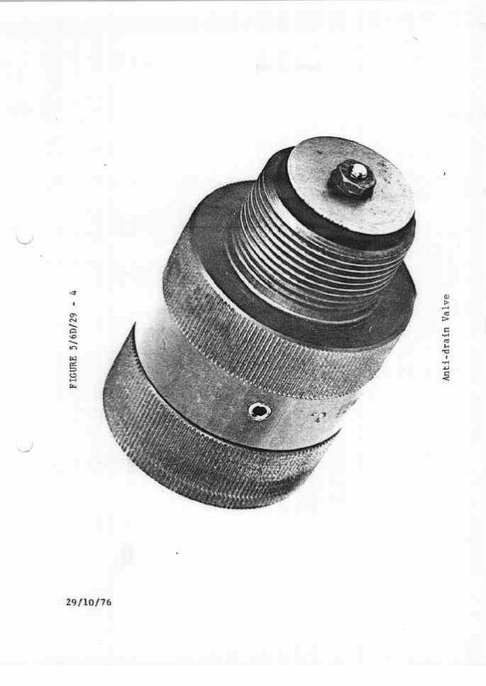
9. Anti-drain valve (see Figure 4) - an anti-drain valve and swivel coupling is fitted on the end of the hose. The anti-drain valve
retains a pressure of not less than 50 kPa.
10. Nozzle - any nozzle fitted with an integral anti-drain valve Which retains a pressure of not less than 10 kPa and which is
located downstream of the main nozzle valve.
11. Marking - instrument data plate(s) sealed to the instrument, marked:
(a> tlapproved for . . ..x.... lubricating oil",
where x is the commercial or technical name; for
example, "Shell Super“ or "SAE 30",
(b) "maximum flow rate 100 litres per minute".
12. Sealing - the following parts of the flowmeter are sealed with
a lead stamping plug:
(a) the meter and indicator (see Figure 2);
(b) the instrument data plate.
The approval includes:
1. The flowmeter with a zero-start Neptune Type 441 indicator with
29/10/76 . ../3
,.,
Technical Schedule No 5/6D/29 Page 3
a scale interval of 1 litre; the first element is marked with ten scale-mark lines numbered from 0 to 9. The aperture through which the first element is viewed is widened in the direction of travel (see Figure 5).
2. The flowmeter with a zero-start Neptune Type 443 indicator and ticket printer. The ticket printer has l-litre increments and the indicator has a scale interval of 1 litre; the first element is marked with ten scale-mark lines numbered from 0 to 9. The aperture through which the first element is viewed is widened in the direction of travel (see Figure 6).
-
3. The flowmeter with a zero-start Neptune Type 444 indicator, ticket printer and set-stop counter. The ticket printer has l-litre increments and the indicator has a scale interval of 1 litre; the first element is marked with ten scale-mark lines
numbered from 0 to 9. The aperture through which the first element is viewed is widened in the direction of travel (see Figure 7).
Special Tests:
The instrument should be tested with the liquid for which it will be used, the name of which is marked on the instrument data plate.
Minimum Delivery:
1. The non-flow-dependent errors are up to:
(a) l-litre rounding error for the ticket printer with l-litre increments;
(b) 0,2-litre reading error for the indicator, which has the first element indicating by l-litre scale intervals;
(c) 0,8-litre hose dilation.
2. When a ticket printer is fitted, the minimum delivery for which
the relative errors from all sources would not exceed 1,5% is 150 litres.
3. Without a ticket printer the minimum delivery for which the
relative errors from all sources would not exceed 1,5% is 100 litres.
Hose Dilation:
A measure of the hose-dilation quantity may be obtained by the
29/10/76 ..*/4

Technical Schedule No 5/6D/29
following method:
Page 4
With the pump stopped and the hose unwound from the reel, open
the nozzle to reduce the pressure in the hose t> the anti-drain
valve retaining pressure of about 50 kPa. Then zero the indicator, start the pump and, after allowing not less than 30 seconds for the hose to fully dilate, read the quantity on the indicator. This quantity is equal to the hose dilation.
Variation of Quantity in Nozzle:
If the integral anti-drain valve in the nozzle is not fitted or is not operating, the quantity of liquid contained in the nozzle and its fittings between the external anti-drain valve and the main nozzle va be ;Jill be an additional non-flow-dependent error for which no allowance has been made in the calculation of minimum delivery.
The efficiency of the integral anti-drain valve may be determined by the following method:
Start the pump, open and close the main nozzle valve, stop the
Pump 9 through the drain plug reduce the hose pressure to less than 55 kPa and then open the nozzle main valve. There should
be no significant draining from the nozzle if the integral anti- drain valve is satisfactory.
29/10/76

NATIONAL STANDARDS COMMISSION -
TECHNICAL SCHEDULE No 5/6D/29
VARIATION No 1
Pattern: Acme (Lubricating Oil) Flowmeter With Neptune 38-mm
Type 4 Meter
Submittor: Acme Oil Equipment Services Pty Ltd, 253 Ingles Street, Port Melbourne, Victoria, 3207
c Date of Approval of Variation: 14 December 1976
The modification described in this Schedule applies to the patterns described in Technical Schedule No 5/6D/29 dated 29 October 1976.
All instruments conforming to this approval shall be marked "NSC No 5/6D/29".
Description:
The approved modification provides for any type, bore or length of hose provided that the minimum delivery determined from Table 1 and marked on the instrument's data plate for reference by the Weights and Measures Authority is acceptable to that Autnority taking into account the usage of the instrument.
Special Tests:
Hose Dilation:
A measure of the hose-dilation quantity may be obtained by the following method:
With the pump stopped and the hose fully wound on its reel, open the nozzle to reduce the pressure in the hose to the anti-drain valve retaining pressure of about 55 kPa. Then fully unwind the hose from the reel, zero the indicator, start the pump and, after allowing not less than 30 seconds for the hose to fully dilate, and with the pump still running, read the quantity on the indicator. This quantity is equal to the maximum hose dilation.
27/l/77
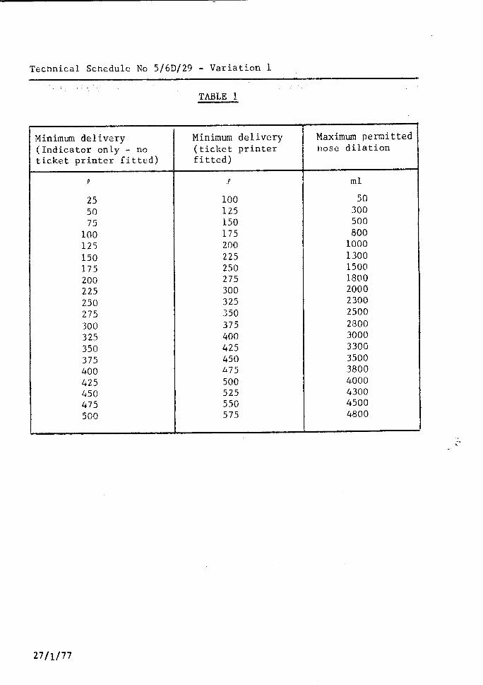
Technical Schedule No 5/60/29 - Variation 1
TABLE 1
Minimum delivery (Indicator only - no ticket printer fitted)
9
25 50 75 100 125 150 175 200 225 250 275 300 325 350 375 400 425 450 475 500
Minimum delivery Maximum permitted (ticket printer hose dilation fitted)
.? ml
100 50 125 300 150 500 175 800 200 1000 225 1300 250 1500 275 1800 300 2000 325 2300 350 2500 375 2800 400 3000 425 3300 450 3500 L75 3800 500 4000 525 4300 550 4500 575 4800
I
27/l/77

NATIONAL STANDARDS COMMISSION -
TECHNICAL SCHEDULE No 5/6D/29
VARIATION No 2
Pattern : Acme (lubricating Oil) Flowmeter With Neptune 38 mm Type 4 Meter
submittor: Acme Oil Equipment Services Pty Ltd 253 Inglee Street Port Melbourne, Victoria, 3207.
1. DescGption of Variant 5
With an internal float valve in the supply tank which replaces the Mowbray low
level float switch and hydraulically operated shut-off valve fitted to the pattern (Figure 8).
28/12/82

TEST PROCEWRE No 5/6D/29
VARIATION No 2
Note: The instrument should be tested with the liquid with which it will be used; - the viscosity range or type of liquid is marked on the data plate.
The maximum permissible errors at verification are:
(al 2 0.3% for all flow rates, when the operating flow rate varies by more than 10 L/min within the approved maximum and minimum flow rates marked on the data plate, the system having been calibrated at the maximum approved flow rate.
(bl 20.15%, when the operating flow rate is within 25% of the nominal flow rate being marked on the data plate.
1. Make at least one delivery at maximum flow rate during which the liquid in the supply tank falls X to the level at which the float valve operates and stops the delivery into the proving measure. Replenish the supply tank
with at least sufficient liquid to allow the delivery to be complei before the liquid level in the supply tank again causes the float valve by operate. The effect on the measured quontity should not create an error which exceeds 1% of the minimum delivery.
2. Test delivery - if the test delivery is less than ten times the minimum delivery, the reading error of the indicator or the rounding error of the ticket printer is minimised by completing the delivery at o graduation line.
20/l 2182
I
29110176
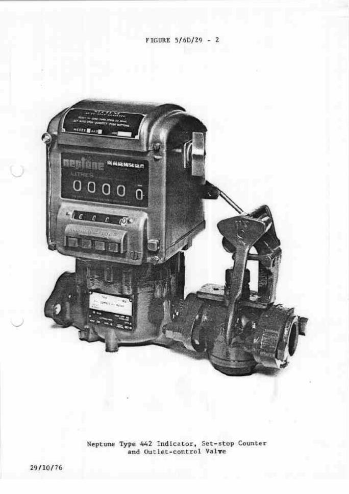
FIGURE 5/6D/29 - 2
Neptune Type 442 Indicator, Set-stop Counter and Outlet-control Valve
29/10/76

9/10/76
29/10/76
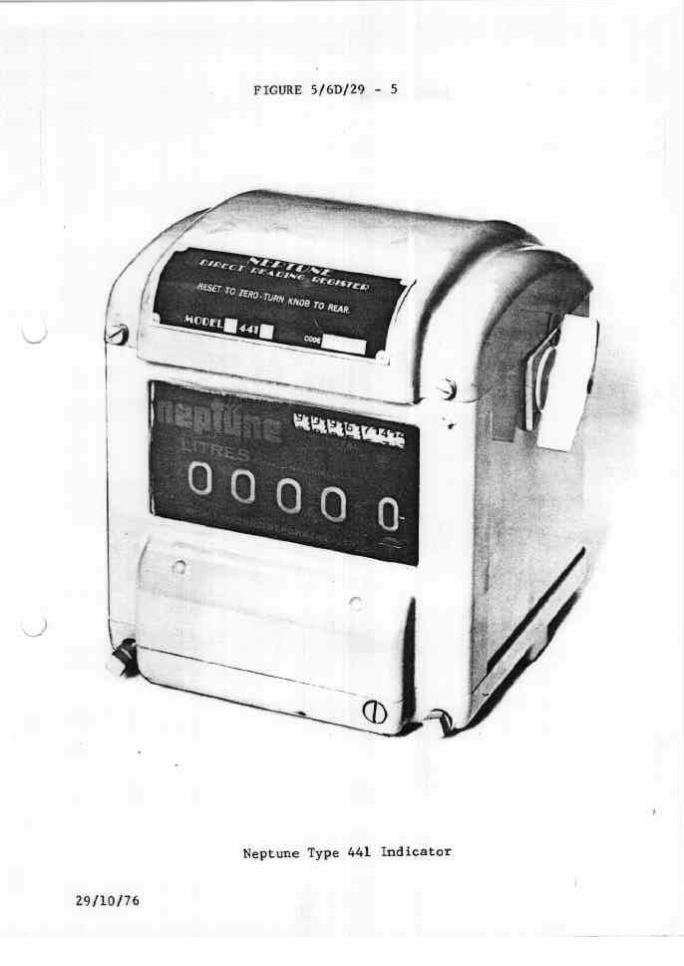
FIGURE 5/6D/29 - 5
Neptune Type 441 Indicator
29/10/76

FIGURE 5/6D/29 - 6
. .
Neptune Type 443 Indicator and Ticket Printer
29/10/76

FIGURE 5/6D/29 - 7
Neptune Type 444 Indicator, Ticket Printer and Set-stop Counter
29/W/76

co
I
E s
28112182