People's Republic of China with Iimited liability) Stock ...
- 1 -
ICS 83.160.01 G 41
National Standard of the People's Republic of China
GB1796.1 – 200X Replaces part of GB 1796-1996
Tyre valves Part 1: Clamp-in valves
(ISO 9413: 1998, Tyre valves – Dimensions and designation, NEQ)
Draft for approval
Issue Date: 200X – XX – XX Implementation Date: 200X – XX – XX
General Administration of Quality Supervision, Inspection and Quarantine of the People's Republic of China
Standardisation Administration of the People's Republic of China (SAC)
Issue

- 2 -
GB 1796.1 - 200X
Foreword Clause 9 of this Part is mandatory while the rest are recommended. GB 1796, “Tyre Valves” is divided into six parts: − Part 1: Clamp-in valves; − Part 2: Rubber base valves; − Part 3: Snap-in valves; − Part 4: Clamp-in tubeless valves; − Part 5: Large core chamber valves; − Part 6: Cores. This is Part 1 of GB 1796, corresponding to ISO 9413: 1998, “Tyre valves – Dimensions and designation”, (English version). The consistency degree of this part and ISO 9413: 1998 is non-equivalent. This Part replaces the “clamp-in valves” Part found in GB 1796– 1996 “Tyre valve”. This part compares to GB 1796-1996, the main changes are: − “terms and definitions” have been added (see Clause 3); − model AA01, AA01C, AB01, AB03C, AB04C and CB11C valves and their corresponding
contents in Table 1 have been added; − model I02, I01C, I04C protective-cap have been added; − certain dimension tolerances have been amended (former edition Clause 5, current edition
Clause 6); − certain valve specifications have been added (former edition Clause 4, current edition Clause 5); − certain valve components specifications have been added (former edition Clause 5, current
edition Clause 6); − model QD5 spacer and model C protective-cap have been withdrawn (former edition Clause 5,
current edition Clause 6); − tooth profile, limit size and tolerance specification for model 5CV and 8CV threads have been
added (see 6.7); − maximum usable pressure for valves has been amended (former edition 6.3, current edition
Clause 8); − installation torque of hexagon nuts has been added (see Clause 10); − air-tightness of the seal-cap has increased (see Clause 11); − “test methods” have been amended (former edition 6.4, current edition Clause 12); − test regulations have been amended (former edition Clause 7, current edition Clause 9); − Appendix A has been amended (former edition Appendix A, current edition Appendix A). Appendix A to this Part is information data. This part is proposed by China Petroleum and Chemical Industry Association (CPCIA). National Technical Committee for Standardisation of Tyres and Rims implemented this Part under centralised management.

- 3 -
Main drafting units of this Part: Shandong Gaotian Hardware Manufacturing Limited; Jiangyin Chuangxin Tyre Valve Co., Ltd Participating drafting units of this Part: Tianjin Bicycle Factory No 2 Branch No 2 Ningbo Jinzhou Shuguang Mechatronics Co., Ltd Foshan Shunde Anchi Industrial Co., Ltd. Main drafters of this Part: LiFeng, LuXiaoYong, LiuHaiYan, ZhangHaoBo, LiZhanGang. This Part replaces certain Parts of the previously issued standards: -GB 1796-1979, GB 1796 – 1988, GB 1796 – 1996.

- 4 -
GB 1796.1 - 200X Tyre Valves
Part 1: Clamp-in valves
1 Scope This Part of GB 1796 specifies the terms and definitions, models and symbols, structural forms, component type, structural sizes and materials, appearance, maximum usable pressure, air-tightness, the installation torque of hexagon nuts and valve end, the air-tightness of seal-cap, test methods, test regulations, labelling, packaging and storage requirements for clamp-in valves (hereinafter abbreviated as valves). This Part applies to valves for motorcycles and cycles.
2 Normative References The provisions of the following documents become provisions of this Standard after being referenced with the quotation GB 1796 Part 1. For dated reference documents, all later amendments (excluding corrigenda) and versions do not apply to this Part; however, the parties to the agreement are encouraged to study whether the latest versions of these documents are applicable. For undated reference documents, the latest versions apply to this Standard. GB 1796.6 Tyre valves, Part 6: cores (GB1796.6-xxxx, ISO9413: 1998, Tyre valves - Dimensions and designation, NEQ) GB/T 2828.1-2003 Sampling procedures for inspection by attributes--part 1: Sampling schemes indexed by acceptance quality limit (AQL) for lot-by-lot inspection (ISO 2859-1: 1999; IDT) GB 9764 Tyre valves – Core chambers (GB 9764 – 1997, neq ISO 6762: 1982; ISO 7442:1982) GB 9765 Tyre valve threads (GB 9765 – 1997, neq ISO 4570-1: 1977, ISO 4570 – 2:1979, ISO 4570 – 3: 1980) GB/T 9766.1 Test method for tyre valve, part 1: Test method for clamp-in valves GB/T 12839 Tyre valves - Terms and definitions (GB/T 12839 – 2005. ISO 3877 – 2: 1997, Tyres, Valves and tubes – list of equivalent terms – part 2: Tyre Valves, NEQ) GB/T XXXX Labelling method for tyre valves and their components (GB/T XXXX – XXXX, ISO 10475: 1992, Valves for tubeless tyres and valves for tubes – Identification system for valves and their components, MOD)
3 Terms and definitions The terms and definitions set out in GB/T 12839 apply to this Part.
4 Models and symbols The models and symbols of the products should conform to the regulations set out in GB/T XXXX. The model in this Part meets the foreign standard model; see Appendix A also.

- 5 -
5 Structural form The structural form of the valves should conform to the requirements shown in Table 1 and Diagrams 1 - 4.
Table 1 Components Model Diagram
Spacer Nut Protective-Cap
Core
Suitable valve hole diameter
mm
Reference Application
AA01
AA01C
Diagram 1 D06 E12, F03 I07 H03C •6.2 Cycles
AB01 Diagram 2 D01 E01, F03, F04C
I07 H04C
AB03C
AB04C
Diagram 3 D15C or D16C
E01C, F02C, F03C
I03C H04C or H05C
CB03 H01
CB07C H01S
CB09C
CB10C
CB11C
Diagram 4 D01 or D02C
E01, F01 or F01C
I01 or I02 or I01C or
I02C or I04C H01
•8.3 Motorcycles or Cycles
1-I07 Protective-Cap; 2-H03C Valve Core; 3-Valve; 4-F03 Rim Nut; 5-E12 Hexagon Nut 6-D06 Spacer
Diagram 1 AA01, AA01C Valve

- 6 -
1- I07 or I03C Protective-Cap; 2- H04C Valve Core; 3-F04C Core Hold-down Nut; 4- Valve; 5- F01 Rim Nut; 6- E01 Hexagon Nut; 7- D01 Spacer;
Diagram 2 AB01 Valve
1-I03C or I07 Protective-Cap; 2-H04C or H05C Valve Core; 3-F03C Core Hold-down Nut; 4-Valve; 5-F02C Rim Nut; 6-E01C Hexagon Nut; 7-D15C or D16C Spacer
Diagram 3 AB03C, AB04C Valve

- 7 -
1- I01 or I02 or I01C or I02C or I04C Protective-Cap; 2- H01 Valve Core; 3-F01 or F01C Rim Nut;
4- Valve; 5- E01 Hexagon Nut; 6- D01 or D02C Spacer;
Diagram 4 CB03, CB07C, CB09C, CB10C, CB11C Valves
6 Models, structural dimensions and materials of components
6.1 Valve The models, structural dimensions and materials of the valves should meet the requirements set out in Table 2 and Diagram 5 - Diagram 8.
Table 2
Model Diagram Core Chamber Model Materials AA01, AA01C Diagram 5 -
AB01 Diagram 6 -
AB03C, AB04C Diagram 7 -
CB07C 1B
CB03, CB09C, CB10C, CB11C
Diagram 8
1A
Brass or other metal materials

- 8 -
Model L AA01 27
AA01C 30
Diagram 5 AA01, AA01C Valve

- 9 -
Diagram 6 AB01 Valve Diagram 7 AB03C, AB04C Valve
Model L d H
CB07Ca 30 15 2.2 CB03 33.5 14 2.7
CB09C 34 2.5
CB10C 46
CB11C 40
18
2.2
a Suitable for H01S valve cores only.
Diagram 8 CB07C, CB03, CB09C ~ CB11C Valves
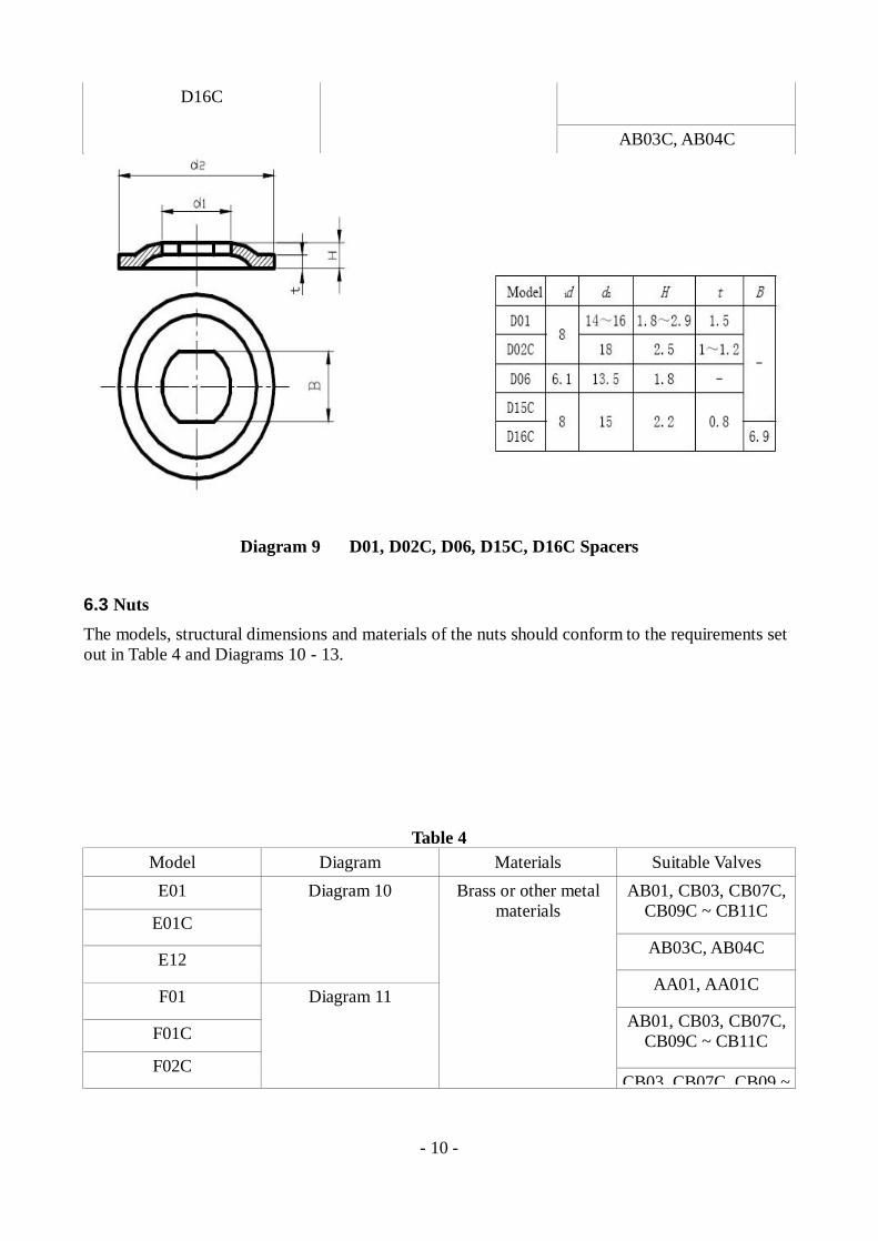
6.2 Spacers The models, structural dimensions and materials of the spacers should conform to the requirements set out in Table 3 and Diagram 9.
Table 3
Model Material Suitable Valves D01 AB01, CB03C, CB07C, CB09C
- CB11C D02C
D06 CB03, CB07C, CB09C -
CB11C D15C
Steel or brass
AB01, AB01C
- 10 -
D16C
AB03C, AB04C
Diagram 9 D01, D02C, D06, D15C, D16C Spacers
6.3 Nuts The models, structural dimensions and materials of the nuts should conform to the requirements set out in Table 4 and Diagrams 10 - 13.
Table 4 Model Diagram Materials Suitable Valves E01 AB01, CB03, CB07C,
CB09C ~ CB11C E01C
AB03C, AB04C E12
Diagram 10
AA01, AA01C F01
F01C AB01, CB03, CB07C,
CB09C ~ CB11C F02C
Diagram 11
Brass or other metal materials
CB03, CB07C, CB09 ~

- 11 -
F03
F03C Diagram 12 AB03C, AB04C
AA01, AA01C
AB03C, AB04C
F04C Diagram 13
AB01
Diagram 10 E01, E12, E01C Hexagon Nuts

- 12 -
Diagram 13 F04C Core Hold-down Nut
6.4 Protective-Cap The models, structural dimensions and materials of the protective cap should conform to the requirements set out in Table 5 and Diagrams14 - 20.
Table 5
Model Diagram Material I07 Diagram 14 Plastic

- 13 -
I03C Diagram 15
I01 Diagram 16
I02 Diagram 17
I01C Diagram 18
Brass, Rubber
I02C Diagram 19
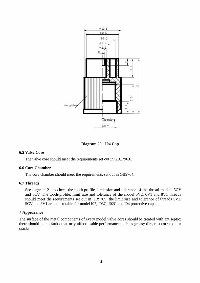
I04C Diagram 20
Plastic
- 14 -
Diagram 20 I04 Cap
6.5 Valve Core The valve core should meet the requirements set out in GB1796.6.
6.6 Core Chamber The core chamber should meet the requirements set out in GB9764.
6.7 Threads See diagram 21 to check the tooth-profile, limit size and tolerance of the thread models 5CV and 8CV. The tooth-profile, limit size and tolerance of the model 5V2, 6V1 and 8V1 threads should meet the requirements set out in GB9765; the limit size and tolerance of threads 5V2, 5CV and 8V1 are not suitable for model I07, I03C, I02C and I04 protective-caps.
7 Appearance The surface of the metal components of every model valve cores should be treated with antiseptic; there should be no faults that may affect usable performance such as greasy dirt, rust-corrosion or cracks.

- 15 -
8 Maximum usable pressure See Table 6 to check the maximum usable pressure for the valves.
Table 6 Valve Models Maximum Usable Pressure
KPa AA01, AA01C 900 CB03, CB07C, CB09C ~ CB11C, AB01, AB03C, AB04C
700
9 Air-tightness Under the maximum specified usable pressure, the air-tightness of the whole valve should be ensured.
10 The installation torque of the hexagon nuts and valve The installation torque of model 6V1 nut is: 2N.m - 3.5N.m; the installation torque of model 8V1, 8CV nuts is: 3N.m - 5N.m.
11 Air-tightness of the seal-cap The maximum seal pressure of model I01, I02 and I01C seal-caps should not be less than 700KPa.
12 Test Methods
12.1 For the appearance test perform a visual examination.
P-Thread Pitch; d-External Thread – Major Diameter;
d1-External Thread – Minor Diameter; d2-External Thread – Pitch Diameter; D-Internal Thread – Major Diameter; D1-Internal Thread – Minor Diameter;
D2-Internal Thread – Pitch Diameter

- 16 -
External Thread
Major Diameter d Pitch Diameter d2 Minor Diameter
d1
Thread Code
Nominal Size
(d x p)
Maximum
Nominal Td
Minimum
Maximum
Nominal Td2
Minimum Maximum
5CV 5.1x1.058 5.05 0.28 4.77 4.36 0.14 4.22 3.75 8CV 8.1x0.847 7.96 0.23 7.73 7.41 0.13 7.28 6.92
Internal Thread
Minor Diameter D1 Pitch Diameter D2 Major Diameter
D
Thread Code
Nominal
Size (d x p)
Maximum
Nominal TD1
Minimum
Maximum
Nominal TD2
Minimum Minimum
5CV 5.1x1.058 4.21 0.26 3.95 4.59 0.18 4.41 5.20 8CV 8.1x0.847 7.34 0.16 7.18 7.72 0.17 7.55 8.1
Diagram 21 Tooth-profile, limit size and tolerance for 5CV and 8CV threads
12.2 Throat diameter and cone position Use a special gauge or general gauge to measure the throat diameter and cone position.
12.3 Pitch diameter and major diameter of external thread; pitch diameter and minor diameter of internal thread, and internal thread depth dimension
Use a thread go-gauge to measure pitch diameter of external thread, pitch diameter of internal thread and internal thread depth. Use a smooth go-gauge, smooth no-go-gauge or general gauge to measure the major diameter of external thread and minor diameter of internal thread.
12.4 Other test methods Other test methods should be carried out according to the requirements set out in GB/T9766.1.
- 17 -
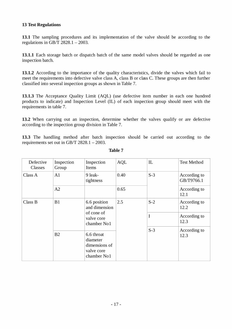
13 Test Regulations
13.1 The sampling procedures and its implementation of the valve should be according to the regulations in GB/T 2828.1 – 2003.
13.1.1 Each storage batch or dispatch batch of the same model valves should be regarded as one inspection batch.
13.1.2 According to the importance of the quality characteristics, divide the valves which fail to meet the requirements into defective valve class A, class B or class C. These groups are then further classified into several inspection groups as shown in Table 7.
13.1.3 The Acceptance Quality Limit (AQL) (use defective item number in each one hundred products to indicate) and Inspection Level (IL) of each inspection group should meet with the requirements in table 7.
13.2 When carrying out an inspection, determine whether the valves qualify or are defective according to the inspection group division in Table 7.
13.3 The handling method after batch inspection should be carried out according to the requirements set out in GB/T 2828.1 – 2003.
Table 7
Defective Classes
Inspection Group
Inspection Items
AQL IL Test Method
A1 9 leak-tightness
0.40 According to GB/T9766.1
Class A
A2 0.65
S-3
According to 12.1
S-2 According to 12.2
I According to 12.3
B1 6.6 position and dimension of cone of valve core chamber No1
Class B
B2 6.6 throat diameter dimensions of valve core chamber No1
2.5
S-3 According to 12.3

- 18 -
B3 6.7 the pitch diameter, minor diameter and depth dimensions of 5V1 thread of valve core chamber
C1 6.7 the pitch diameter and major diameter of external thread of 8CV valve
C2 6.7 the pitch diameter and major diameter of external thread of 8V1 valve mouth
C3 6.7 the pitch diameter and major diameter of external thread of 6V1 valve
Class C
C4 6.7 The pitch diameter and minor diameter of Internal thread of 8CV hexagon nut
C5 6.7 The pitch diameter and minor diameter of Internal thread of 6V1 nut
Class C
C6 6.7 The pitch diameter and minor diameter of Internal thread of 8V1 nut
Class C C7 6.7 The pitch diameter and
6.5 S-3

- 19 -
According to GB/T9766.1
C8 6.7 The pitch diameter and minor diameter of Internal thread of rim nut
C9 10 Installation torque of hexagon nut and valve
C10 11 Leak-tightness of seal-cap
4.0
According to GB/T9766.1
S-3 According to 12.2
C11 6.1 specified valve throat dimension of model AB01, AB03C, AB04C
C12
6.5
I According to 12.1
C13 10 II According to 12.2
14 Labelling, packaging and storage
14.1 Labelling There labelling on the outer packaging of the valves should indicate the:
a) name and address of the manufacturer, trademark; b) product name,; c) product model; d) quantity e) production date
- 20 -
14.2 Packaging
14.2.1 Products can be either packed as sets or as individual components.
14.2.2 Use a plastic bag for the inner packaging and a cardboard or wooden box for the outer packaging.
14.2.3 A copy of the product qualification certificate should be enclosed in the inside packaging box (bag).
14.3 Storage The products should be stored in a dry, well-ventilated, anti-corrosion and greasy-dirt free warehouse, away from high temperature and sunlight.

- 21 -
Appendix A
(Information appendix) Models in this Part in comparison to overseas models
Table A.1 presents the comparison table for models of this part and overseas models
Table A.1