National Standard for the People’s Republic of · PDF fileNational Standard for the...
109
I ICS 29.120.99 K 32 National Standard for the People’s Republic of China GB 17885—200× In replacement of GB 17885-1999 Electromechanical contactors for household and similar purposes (IEC 61095:2000, MOD) (Draft for Approval) Release on ××/××/200× Implemented on ××/××/200× Issued by General Administration of Quality Supervision, Inspection and Quarantine of the People’s Republic of China Standardization Administration of the People’s Republic of China
Transcript of National Standard for the People’s Republic of · PDF fileNational Standard for the...

I
ICS 29.120.99 K 32
National Standard for the People’s Republic of China
GB 17885—200× In replacement of GB 17885-1999
Electromechanical contactors for household and similar purposes
(IEC 61095:2000, MOD)
(Draft for Approval)
Release on ××/××/200× Implemented on ××/××/200× Issued by
General Administration of Quality Supervision, Inspection and Quarantine of the People’s Republic of China
Standardization Administration of the People’s Republic of China

GB 17885—200×
Table of Contents Introduction
1 Scope
2 Standard documents
3 Terminology and Definition:
4 Classification
5 Features
6 Marking, installations and maintenance
7 Normal usage, installation and transport conditions
8 Structural and performance requirements
9 Test
Appendix A (Guideline Appendix) Contactor Terminal Marking and Identification
Appendix B (Guideline Appendix) Procedure Test and Sample Quantity
Appendix C (Guideline Appendix) Instructions for Load Circuit Adjustment
Appendix D (Guideline Appendix) Methods for Identifying Short Circuit Power Factor
Appendix E (Guideline Appendix) Measurement of Clearance and Creepage Distance
Appendix F (Guideline Appendix) Contactor’s Rated Impulse Withstand Voltage
Appendix G (Guideline Appendix) Electrically Heated Wire Ignition Test
GB 17885—200×
Introduction
All technical contents of this Standard are compulsory. The amendment to the Standard has adopted IEC 61095:2000-10 Ed.1.1, Electromechanical Contactors for Household and Similar Purposes. The technical contents and compiling format of this Standard are in compliance with IEC 61095. When adopting IEC 61095:2000-10 Ed.1.1, amendments have been made according to the actual conditions of China. Technical differences have been marked with vertical lines in the side margins of the corresponding body texts. Additional notes on the differences of this Standard and IEC are as follows:
1. 3.6 has been added,not included in IEC61095:2000.
2. “8.2.6 On and Off Overvoltage” has been removed from IEC 61095:2000.10 Ed1.1. “5.1g)”, “5.8” and “6.1.2n)” have also been removed. Numbering for “9.3.3.5.4” and subsequent items have been changed accordingly.
3. For testing procedures in 9.2.3, see “GB 14048.1-2006, Appendix C”. IEC testing procedures are still under discussion.
4. The output factor in Table 16, IEC 61095:2000, was incorrect as ±0. 5. This has been amended to ±0. 05 in the current Standard.
5. 690V rated insulation voltage has been added in Note e for Table 20. This Standard is an amendment for GB 17885-1999, Electromechanical Contactors for Household and Similar Purposes. The main differences are:
1. GB 17885-1999 only contains terminologies listed in IEC 1095:1992, but not in GB/T 2900.18—1992. Now all terminologies are included.
2. “Rated frequency should be in compliance with GB/T 1980” has been removed from 5.3.3.
3. 7.1.4 General Condition for Electromagnetic Environment has been added. 4. 8.1.10 has been amended as “For testing procedures in 9.2.3, see “GB 14048.1-2006,
Appendix C”. 5. 8.3 Electromagnetic Compatibility has been added, including 8.3.1 Immunity and
8.3.2 Emission. 6. In 9.2.1.6, Chinese wording has been amended for CTI. “CTI for insulation materials
are essential data for identifying creepage distance” have been removed from 9.2.1.6: 9.1.2o) and Appendix B, Table B1: E-f.
7. In 9.2.3, for testing procedures, see “GB 14048.1-2006, Appendix C”. 8. In 9.2.4.3, height changed from 75m to 75mm. 9. 9.2.5.1, 3rd paragraph: Chinese wording amendment;5th paragraph: Chinese wording
amendment. 10. In 9.2.5.2.2 “spherical surface testing device” changed to “spherical testing device”;
1st,“dropping and oscillating” changed to “dropping or oscillating”;2nd paragraph: “vertical height” changed to “vertical distance”.
11. 9.2.6 Chinese wording amendment.
GB 17885—200×
12. 9.3.3.4.1b) “withstand voltage test not necessary” changed to “impulse withstand voltage
test not necessary”;Notes amendments are per GB 14048.1-2006 8.3.3.4.1d).
13. 9.3.4.2.2 “……current limits……,……as per maximum Iq of components ……”
has been changed to “……limited current……,……as per maximum allowed peak
current Ip……”.
14. 9.3.4.2.3 “……and Iq current test passed:”has been changed to “……and Iq current (if applicable) test passed:”
15. Addition of Figure 10 Hinge Joint. 16. Notes added for Appendix A, A.2.2. 17. Addition of G4 in Appendix G.
This Standard is in replacement of GB17885-1999. Appendices A-G are as standard. This Standard has been brought forward by China Electric Tool Association. This Standard is administered by China National Standardization Technical Committee of LVEA. Drafted by: Shanghai Electrical Apparatus Research Institute (Group) Co., Ltd Co-drafted by: Zhejiang Zheng Tai Electric CO., LTD., Renmin Electrical Appliance Co., Ltd、SASSIN International Electric Co.,Ltd、Delixi Electric Co.,Ltd、Tianshui 213
Electrical Apparatus Co.Ltd、Schneider Electric (China) Investment Co.,Ltd. Drafted by: ZEN Ping, JIA Feng Co-drafted by: XIAO Hongwei, GAO Wengle, SU Hanlin, HUANG Rongrong, ZHENG Shiquan, GAO Weidong, ZENG Hui. Replaced earlier version: GB 17885-1999.

GB 17885—200×
Electromechanical contactors for household and similar purposes
1 Scope The standard provides specifications for the use of household and similar
electromechanical contactors, the main contacts of which are used to connect to the circuits that meet the following requirements: The rated voltage does not exceed 440V; the rated operating current under the category AC-7a is less than or equal to 63A, while the current limit under category AC-7b is less than or equal to 32A and its rated short-circuit current is less than or equals to 6KA.
The contactors to which the standard applies are generally not used for short-circuit breaking current. Therefore the appropriate electrical short-circuit protection should be installed as part of it when used. (see 9.3.4)
This standard does not apply to the following electrical devices:
a) Contactors in compliance with GB 14048.4 b) Semiconductor contactors c) Contactors for special purpose d) Contactor’s auxiliary contact (relevant requirements see GB 14048.5)
The requirements of this standard are as follows:
a) The characteristics of contactors b) The contactor shall meet the following requirements:
1) Operation and performance 2) Dielectric properties 3) Housing protection rating 4) Structure 5) The properties of EMC
c) The tests and test methods adopted to meet the above conditions d) Submitting verified test procedures and test sample quantity e) The parameters provided by contactors or by manufacturer samples
2 Standard documents By quoting in this standard, the terms in the following documents become standard terms.
Any quoted documents with dates, and all its subsequent amendments to a single (not including the contents of corrigenda) or revised edition, are not applicable to this standard. However, relevant parties who reach an agreement according to the standard are encouraged to researches into whether the latest versions of these documents should be used. For documents without a quoted date, the latest version applies to this standard.
GB/T 2423.3-2006 Electrical and Electronic Products Environmental Testing part II Testing method Trial Cab: Constant damp heat test (IEC 60068-2-78:2001, IDT)
GB/T 2900.18-2008 Electrical terms Low-voltage electrical devices
GB/T 4025-2003 Man-machine interface markings and identification of the basic methods and safety rules; Encoding rules of the indicators and operators (IEC 60073:1996, IDT)

GB 17885—200×
GB/T 4026-2004 Man-machine interface markings and identification of the basic methods and safety rules; General rules on markings of device terminals and conductor terminals and specific alphanumeric system (IEC 60445-1999, IDT)
GB/T 4205-2003 Man-machine interface (MMI); Operating rules (IEC 60447:1993, IDT)
GB/T 4207-2003 The measuring methods for CTI and CTI withstand for solid insulated materials under moisture (IEC 60112:1979, IDT)
GB/T 5169.10-2006 Electrical and electronic product fire risk test; Part 10 glow wire/ hot wire test method; finished glow wire ignition test (idt, IEC 60695-2-10:2000)
GB/T 5465.2-2008 Electrical device graphic symbols Part 2: Graphic symbols (IEC 60417 DB:2007, IDT)
GB/T 11020-2005 List of test methods for solid non-metallic materials when exposed to fire (IEC 60707:1999,IDT)
GB/T 11021-2007 Electrical insulation Heat-resistant grade (IEC 60085:2004, IDT)
GB/T 11026.1-2003 Electrical insulation material; Heat resistance
Part 1: Aging procedures and test results of the assessment (IEC 60216-1:2001, IDΤ)
GB 14048.1-2006 Low voltage switch device and control device
Part 1: General principle (IEC 60947-1: 2001, MOD)
GB 14048.4-2003 Low voltage switch device and control device
Electromechanical contactors and motor starter (IEC 60947-4:2000, IDT)
GB 14048.5-2008 Low voltage switch device and control device
Part 5-1 Control circuitry and electrical components
Switching device control circuit electrical (MOD IEC 60947-5-1:2003)
GB/T 16895.12-2001 Electrical installations in buildings; Part 4: Security
Chapter 44: Overvoltage protection
No.433: Atmosphere overvoltage or operating overvoltage protection
(idt IEC 60364-4-433:1995)
GB/T 16935.1-2008 Low-pressure system device and insulation coordination
Part 1: Principles, requirements and tests (idt IEC 60664-1:2007)
IEC 60050(151):1978 International Electrotechnical Terminology
GB 17885—200×
Part 151: Electric and magnetic devices
IEC 60050(441):1984 International Electrotechnical Terminology
Part 441: switch device control device and fuse
IEC 60050(604):1987 International Electro-technical Vocabulary
Part 604: Operation of power transmission and distribution
IEC 60050(826):1982 International Electrotechnical Terminology
Part 826: Electrical installations
IEC 60028 Copper resistance
ISO 2039-2-1987 Plastic-hardness identification; Part 2: Rockwell hardness
3 Terminology and Definition: The standard terminology and the relevant terminology and definitions specified by GB/T 2900.18
3.1 Basic Terminology
3.1.1
Over-current
Any current over the rated current (441-11-06)
3.1.2
Short-circuit
Through a low resistor or resistance, two or more points at different voltage circuit are connected accidentally or intentionally under normal circumstances. (151-03-41)
3.1.3
Short-circuit current
Over-current caused by a short circuit due to circuit failure or connection error. (411-11-07)
3.1.4
Overload
The operating conditions of over-current generated in the normal circuit. (441-11-08)

GB 17885—200×
3.1.5
Overload current
The over-current that has not been damaged in the circuit.
3.1.6
Ambient air temperature
Under the specified conditions, the air temperature surrounds the entire switching device or fuse control. (441-11-13)
Note: For switching device or fuse that has an enclosing housing, the temperature is the housing temperature.
3.1.7
Conductive part
The conductor, but not necessarily part of current work load. (441-11-09)
3.1.8
Exposed conductive part
Under normal circumstances, the conductive parts, which are easily-reached by
operators, are not live. But under fault conditions, they can become live. (411-11-10)
Note: Typical exposed parts such as exposed wall, operating handle and so on.
3.1.9
Electric shock
The physiological and pathological effects that are caused by the current when it passes human or animal body. (826-03-04)
3.1.10
Live part
When the conductor and the conductive parts are normally live, the neutral conductor is included. But in common practice, it does not include the PEN conductor. (826-03-01)
Note: This does not necessarily include the risk of electric shock.
3.1.11
Protective part

GB 17885—200×
In order to prevent electric shock, some measures are taken to connect the required conductor to the following components. The connected parts include:
----------exposed conductive parts
----------external conductive parts
----------the main terminal
----------ground electrode
----------power point or artificial neutral point grounding (826-04-05)
3.1.12
Neutral conductor
The conductor that is connected to the neutral point and is capable of transmitting power (826-01-03)
Note: Under certain circumstances, the functions of neutral conductor and protective conductor are combined at the condition specified. The conductor is called the PEN conductor (Symbol PEN)
3.1.13
Enclosure
Enclosure can provide a required specified protection level to external influences and prevent approaching or touching live parts or the operating component.
Note: This definition is similar to the definition of complete circuit IEV 441-13-01
3.1.14
Integral enclosure
The integral enclosure belongs to the whole electrical part and is indispensable.
3.1.15
Utilization category
With electrical devices or fuses, it accomplishes the combinations that relevant regulation of running conditions demands, being used to indicate the actual characteristics of use. (441-17-19)
Note: The requirements may include the making (if applicable) and breaking capabilities, other characteristics, the circuit connections as well as the condition of use and relevant performance.
GB 17885—200×
3.2 Switching devices
3.2.1
Switching device
The switching device is one that makes or breaks one or more electrical circuits in the current. (441-14-01)
3.2.2
Mechanical switching device
The mechanical switching device depends on the motion of detachable contactor to close contact or disconnect one or more circuits. (441-14-02)
Note: Any mechanical switching device can be accordingly named by the medium (for example, air, SF6, oil) in which the contactor is open or closed.
3.2.3
Semiconductor switching devices
The switching devices that connect or disconnect circuit current by the controlled conductivity of the semiconductor.
Note: Semiconductor switching device is also used to break electrical current, so this definition is different from the definition of IEV441-14-03.
3.2.4
Fuse
When the current exceeds the set value for a long enough time, the circuit and its access points are disconnected through the fuse or some specially designed corresponding parts. All the components that formed the complete electrical devices are included in fuse. (441-18-01)
3.2.5
Circuit-breaker
The circuit-breaker is a mechanic switching device, which is not only capable of making, loading and breaking the current circuit under normal conditions, but is also able to make, load (for a certain period of time) and break current under abnormal conditions (such as short-circuit) (441-14-20)

GB 17885—200×
3.2.6
Contactor (mechanical)
The contactor is a non-manual operation mechanical switching device, which is equipped with only one position of rest that can make, load and break current under normal circuit conditions (including overload operating conditions) (441-14-33)
Note 1: The term “non-manual operation” means that electrical devices can be controlled and maintained at an operation by using one or more of the available external power.
Note 2: In French, the main contact closes at the position of rest is often referred to as “rupteur”, but in English it has no equivalent.
Note 3: The contactor is frequently used in operation.
3.2.7
Electromagnetic contactor
The contactor, which is generated by the electromagnet, makes and breaks the main contact or breaks the contactor on the main contact.
3.2.8
Latched contactor
The latched contactor refers to a kind of contactor that can deter the movable parts from returning to the position of rest with the help of latched device when the actuator loses power. (441-14-34)
Note 1: The latching and releasing of the latched body could be mechanical, magnetic, electric and by gas, etc.
Note 2: As a result of latched body, it in fact has two positions of rest. In the strict sense, it cannot be defined as a contactor. But its usage and design are close to those of a contactor. So it is more appropriate that it meets the requirements of a contactor on certain occasions.
3.2.9
Semiconductor contactor (solid state contactor)
By use of the semiconductor contactor, the function of an electrical contactor can be achieved.
Note: Semiconductor contact switch can also include switching device.
3.2.10
Pilot switch

GB 17885—200×
The pilot switch is a non-manually controlled switch, which is reacted under the required actuating momentum.
Note: The actuating momentum can be pressure, temperature, speed, level, time and so on.
3.2.11
Push-button
The push-button is an actuator operated by a certain part of the body (usually finger or the palm of a hand) and also is a control switch that is equipped with resetting function (spring) (441-14-53)
3.2.12
SCPD Short circuit protective device
SCPD is the device that protects circuit or the circuit components from damage by breaking a short circuit current.
3.2.13
Surge arrester
The surge arrester protects the electrical devices against high transient overvoltage and restricts time of afterflow and amplitude. (604-03-51)
3.3 Switch electrical components
3.3.1
Pole of a switching device
It is the electrical part that is only connected to a single conductive path of the switching device’s main circuit. It does not include the part that is used to fix all the poles together and operate them simultaneously. (441-15-01)
Note: If the switching device has only one pole, it is known as a unipolar switching device. If the switching device is linked together and operated by two or more poles, it is referred as a multi-polar (bipolar, 3-pole, etc) switching device.
3.3.2
Main circuit (of a switching device)
The main circuit is the switching device’s main conductive parts for closing or breaking a circuit. (441-15-02)
3.3.3
Control circuit (of a switching device)

GB 17885—200×
Apart from the main circuit, all conductive parts of the switching device that are used for closing or breaking a circuit. (441-15-03)
3.3.4
Auxiliary circuit (of a switching device)
Apart from the main circuit and control circuit, all conductive parts of the switching device. (441-15-04)
Note: Some auxiliary circuits are used as additional functions, such as signal, interlocking, etc. At this time, these circuits can also be a part of a control circuit of another switching device.
3.3.5
Contact (if a mechanical switching device)
For two or more conductors, the circuit is connected when they are in contact. They close or break the circuit when operated due to their relative movements, or keep the circuit connected by rotating or sliding the contacts. (441-15-05)
3.3.6
Contact piece
The contact piece constitutes a part of the conductive parts. (441-15-06)
3.3.7
Main contact
The electrical contact of the main circuit of the switching device, which is carrying the main circuit’s current. (441-15-07)
3.3.8
Control contact
The control contact is connected by the control circuit in the electric switch, and it is operated mechanically by this switching device. (441-15-09)
3.3.9
Auxiliary contact
The auxiliary control is connected by the auxiliary contact in the switching device and is operated mechanically by this electric switch. (441-15-10)

GB 17885—200×
3.3.10
Auxiliary switch (of a mechanical switching device)
The auxiliary switch is a kind of switch that has one or more control and (or) auxiliary contacts and is also operated mechanically by the mechanical switch. (441-15-11)
3.3.11
“A” contact, make contact
“A” contact, a kind of control contact or auxiliary contact, closes when the main contact of mechanical switch device closes and breaks when the main contact breaks. (441-15-12)
3.3.12
“B” contact, break contact
“B” contact, a kind of control contact or auxiliary contact, breaks when the main contact of the mechanic switch device closes, and closes when the main contact breaks. (441-15-13)
3.3.13
Release (of a mechanical switching device)
The release, which is linked with mechanical switching device, is used to release the Retention Mechanism to close or break the switching device. (441-15-17)
Note: The release can be operated instantaneously or with a delay.
3.3.14
Actuating system (of a mechanical switching device)
All the operating component that deliver the actuating power to the contact of the mechanical switching device.
Note: Actuating system can be mechanical, electromagnetic, hydraulic, pneumatic thermokinetic, etc.
3.3.15
Actuator
The actuator is the part that exerts force on the actuating system by external power. (441-15-22)
Note: The actuator can be in the form of a handle, knob, button, trolley or a plunger.
3.3.16
Position indicating device
GB 17885—200×
The position indicating device is a device that indicates whether a mechanical switching device is open, closed or (if necessary) indicates the ground point. (441-15-25)
3.3.17
Terminal
The terminal, the conductive part, is the device that is used to connect to the external circuit.
3.3.18
Screw-type terminal
A screw-type terminal is used to tighten and loosen wires or can also be used to connect two or more conductors. The connection can be made using different screws and nuts directly or indirectly.
3.3.19
Screwless-type terminal
A screwless-type terminal is used to tighten and loosen wires or can also be used to connect two or more conductors. The connection can be made using springs, the cuniform blocks, eccentrics or cone wheels directly or indirectly.
3.3.21
Thread-cutting tapping screw
Equipped with discontinuous self-tapping screw thread, the screw thread can remove the material in the hole (see Figure 2 for an example)
3.3.22
Clamping unit
The clamping unit is essential for the conductor’s mechanical fastening or the electrical connection.
3.3.23
Unprepared conductor
The unprepared conductor is a conductor which is chipped and then stripped of its insulation for the purpose of inserting into the terminal.
Note: Conductors whose shape has been adjusted so as to be inserted into terminals, or with twisted wires together at the ends, are considered unprepared conductors.
GB 17885—200×
3.3.24
Prepared conductor
Conductors that have wires welded together or cable connectors or loops fitted at their end are considered prepared conductors.
3.4 Operation of switching device
3.4.1
Operation (of a mechanical switching device)
Operation refers to moving a contact from one location to the next location. (441-16-01)
Note 1: As for circuit breaker, it can be a making or breaking operation.
Note 2: For clarity, the operation in the electrical sense, for example, making or breaking, is a switching operation. But in the sense of opening or closing, for example, is a mechanical operation.
3.4.2
Operation cycle (of a mechanical switching device)
Operation cycle refers to the continuous operation — the conversion from one location to another and then return to the position of rest. If there are multiple positions, all other positions need to be passed. (441-16-02)
3.4.3
Operating sequence (of a mechanical switching device)
In the required time internal, required continuous operations are completed. (441-16-03)
3.4.4
Automatic control
Automatic control refers to unattended operation, which is controlled in accordance with the specified conditions. (441-16-05)
3.4.5
Closing operation (of a mechanical switching device)
The device changes from the open position to the closed position.
3.4.6
Opening operation (of a mechanical switching device)

GB 17885—200×
The device changes from the closed position to the open position
3.4.7
Closed position (of a mechanical switching device)
The closed position is the position that ensures the contact in the main circuit in the predefined open position. (441-16-22)
3.4.8
Open position (of a mechanical switching device)
The open position ensures that the breaking contact in the main circuit meets the requirements of predefined medium withstand voltage location.
Note: The above definition is different from the requirements of the properties of the medium
specified in IEV441-16-23
3.4.9
Position of rest (of a contactor)
When the contactor solenoid or compressed air mechanism is not in operation, the position of the movable parts is the position of rest. (441-16-24)
3.4.10
Inching (jogging)
Making or breaking the motor or the coil circuit multiple times within a very short time, moving the driven mechanism slightly.
3.4.11
Plugging
To make an operating motor stop or reverse by using reverse-phase motor stator windings of the motor sequence.
3.5 Feature measurements
3.5.1
Nominal value
The nominal value is the suitable approximate value used to mark or identify a switch or electrical components and devices. (151-04-01)
GB 17885—200×
3.5.2
Limiting value
The limited value is a value of the maximum or minimum allowable in norms or standards.
(151-04-02)
3.5.3
Rated value
Under the required operating condition, the value generally given by manufacturers to a switch or electrical components or devices. (151-04-03)
3.5.4
Rating
A group rating and operating conditions (151-04-04)
3.5.5
Prospective current (of a circuit and with respect to a switching device or a fuse)
The prospective current is the current that may flow through the circuit when the electrical switch or fuse to each pole is replaced by a conductor whose resistance can be ignored. (441-17-01)
Note: The methods used to assess and indicate current will be specified in the relevant standard.
3.5.6
Prospective peak-current
The transient current at the expected peak after the circuit is connected. (441-17-02)
Note: This definition is made under the assumption that an ideal switch is connected, that is, one which has infinite resistance during its off state and no current limit during its on state. The current can pass through several paths, that is, a multi-polar circuit. This definition further assumes that the current at all poles is connected at the same time or even only single polar current may be considered.
3.5.7
Maximum prospective peak current (of an AC circuit)
This is the maximum transient prospective peak current possible. (441-17-04)
GB 17885—200×
Note: For the multi-polar device in multi-phase circuit, the maximum prospective current only considers one polar.
3.5.8
Breaking current (of a switching devices or a fuse)
In the process of breaking, the current flows through one pole of switching device or fuse, generating the instantaneous flow arc. (441-17-07)
Note: For AC current, the current is indicated by RMS Symmetrical AC Component.
3.5.9
Breaking capacity (of a switching device or a fuse)
Under the specified conditions and performance, a switch or fuse can be capable of breaking the prospective value of breaking current under a provided voltage. (441-17-08)
Note 1: Required voltage and condition are seen in the relevant product standards.
Note 2: AC current is indicated by symmetrical AC component value.
Note 3: The making capability of short circuit is shown in 3.5.11.
3.5.10
Making capacity (of a switching device)
Under the specified condition of use and performance, the predictive making current value of the switching device under the specified voltage. (441-17-09)
Note 1: For specified voltage and condition, see product standard.
Note 2: For short-circuit making capacity, see 3.5.11.
3.5.11
Short-circuit breaking capacity
Under the required condition, the capacity to break, including the short circuit of the terminal switching device. (441-17-11)
3.5.12
Short-circuit making capacity
Under the required condition, the capacity to connect, including the short-circuit terminal switching device. (441-17-10)
3.5.13
GB 17885—200×
Joule integral (I2t)
The square of the current over a given time (441-18-23)
3.5.14
Cut-off current; let-through current
The maximum transient current gained at the point of breaking the switching device or the fuse. (441-17-12)
Note: When the circuit has yet to reach its prospective peak current, the concept of breaking the switching device or the fuse is particularly significant.
3.5.15
Applied voltage (for a switching device)
Before the current accesses, the applied voltage is added at two poles between terminals. (441-17-24)
Note: This definition is applicable to a single pole device. For a multi-polar device, applied voltage means the relative phase voltage of the device power terminal.
3.5.16
Recovery voltage
The voltage occurred at one polar of the switching device or between the terminals of the fuse after breaking the current. (441-17-25)
Note 1: The voltage can be considered as two consecutive stages, namely the transient recovery voltage and frequency or power frequency or steady-state recovery voltage
Note 2: This definition is applicable for a single pole device. For a multi-polar device, applied voltage means the relative phase voltage of the device power terminal.
3.5.17
Transient recovery voltage (abbrev:TRV)
The recovery voltage with obvious features of transient at the time. (441-17-26)
Note: Transient voltage can be oscillatory or non-oscillatory or a combination of the two, which depends upon the features of the circuit, switching devices or fuse transient voltage, including the multi-phase neutral point voltage shift.
3.5.18
GB 17885—200×
Power frequency recovery voltage
Recovery voltage after the disappearance of the transient voltage (441-17-27)
3.5.19
DC steady-state recovery voltage
Recovery voltage after the disappearance of the transient voltage in DC circuit. If ripple exists, the voltage can be indicated by the average value. (441-17-28)
3.5.20
Clearance
The shortest straight-line distance between two conductive parts with a potential difference. (441-17-31)
3.5.21
Creepage distance
The shortest distance along the surface of the insulating material between two conductive parts with a potential difference.
Note: The segment between the two insinuating parts is considered as one part of the surface.
3.5.22
Working voltage
Refers to the maximum AC voltage or DC voltage that occurs in part of any insulation end at the highest rated power supply voltage, when it is open-circuit or under normal operating conditions and transient phenomenon is not taken into account.
3.5.23
Switching overvoltage
Due to a specific operation or a fault in the system, at a certain location in the system
the transient overvoltage occurs
3.5.24
Impulse withstand voltage
Under the required test conditions, the highest impulsive voltage of a certain shape or polarity that does not cause disruptive discharge is referred to as impulse highest peak voltage.
3.5.25

GB 17885—200×
Power-frequency withstand voltage
Under the required test conditions, the value that does not cause the disruptive discharge of the power frequency sine voltage.
3.5.26
Pollution
Any solids, liquid or gas (free gas) that can affect the dielectric strength or surface resistivity of the external material.
3.5.27
Pollution degree (of environmental conditions)
The classification of environmental conditions is according to the magnitude of the conductive dust or moisture absorption dusts, free gas or salt and relative humidity, and the frequency of the occurrences of the decrease of surface dielectric strength and / or resistance due to moisture absorption.
Note 1: The pollution degree of the exposed devices is different from the pollution degree in the macroeconomic environment, which provides enclosure or internal heating to prevent moisture absorption.
Note 2: The pollution degree in this standard refers to the pollution degree in micro-environment.
3.5.28
Micro-environment
Ambient conditions of the clearance and creepage distance.
Note: The micro-environment of the clearance or creepage distance affects the insulation, rather than the device environment. The micro-environment might be better or worse than the device environment, including all the factors that affect insulation, such as climatic conditions, electromagnetic conditions, or pollution degree, etc.
3.5.29
Overvoltage category (of a circuit or within an electrical system)
The classification is based on the prospective transient overvoltage and the methods restricting overvoltage in the restrictive (or control) circuit (or electrical system with different nominal voltage).
Note: In an electrical system, the conversion from an overvoltage category to another lower overvoltage category is achieved through lowering the transient overvoltage to a lower
GB 17885—200×
overvoltage category surface. For example, use overvoltage protection or a combination of connections in series and in parallel.
3.5.30
Co-ordination of insulation
On one hand, the insulating properties of the electrical device are related to the characteristics of the expected overvoltage and overvoltage protection device. On the other hand, they are related to the expected micro-environment and the pollution protection method.
3.5.31
Homogeneous (uniform) field
This refers to the electric fields where the electrode voltage gradient is basically constant. For example, between two balls, the radius of each ball is larger than area of the electric field.
3.5.32
Inhomogeneous (non-uniform) field
Refers to the electric fields where the electrode voltage gradient is not constant.
3.5.33
Tracking
With the combination of electric stress and electrolysis impurities, the conductive circuit of the surface of the solid insulating materials is gradually formed.
3.5.34
Comparative tracking index (CTI)
The maximum voltage (volt) under which the material can undertake 50 electrolyte drops without showing the marks of tracking.
Note 1: Each test voltage value and the value of CTI should be divided by 25.
Note 2: The above definition is based upon GB/T 4207-2003 2.3.
3.6 Signs
a) Ic: Making and breaking the current
b) Ie: Rated operating current
c) Ur: Power frequency recovery voltage
d) Ue: Rated operating voltage

GB 17885—200×
e) cosΦ: Power factor
f) Uimp: Rated voltage impulse tolerance
g) Ui: Rated insulation voltage
h) SCPD: Short circuit protection device
i) SELV: Secure ultra-low voltage
j) CTI: Comparative tracking index
4 Classification Contactors in 5.2 in this standard can be used as the basis for classification
5 Features 5.1 Feature overview
Features must be indicated by the following items:
a) The type of the contactor (see 5.2);
b) The rated value and restrictive value of the main circuit (see 5.3);
c) Usage categories (see 5.4);
d) The control circuit (see 5.5);
e) The auxiliary circuit (see 5.6);
f) The performance under short-circuit conditions (see 5.7);
5.2 The type of the contactors
The requirements are as follows (also in reference to 6):
5.2.1 Polar
5.2.2 Control method
a) Automatic (controlled by indicator switch or program-controlled);
b) Non-automatic (for example, manual operation or button operation);
c) Semi-automatic (partly automatic and partly non-automatic).
5.3 The rated value and restrictive value of the main circuit
The rated value of the contactors and starters should be indicated as per 5.3.1 to 5.4 and 5.7 to 5.8, which can be increased or decreased according to the need.
GB 17885—200×
5.3.1 Rated voltage
The contacts provide for the following rated voltage.
5.3.1.1 Rated operating voltage (Ue)
The rated voltage of the contactor, a value that determines the use of the contactors with the combination of the rated operating current is related with the relevant test and usage category.
For a single pole contactor, the voltage at cross-polar ends (contact disconnect location) is generally stipulated as rated operating voltage. For multi-pole contactors, the phase voltage is stipulated as rated operating voltage.
Note 1: By different jobs and usage category, contactors can be used to determine multiple rated voltage and rated operating current or power;
Note 2: By different jobs and usage category, contactors can be used to determine multiple rated voltage and relevant making and breaking capabilities;
Note 3: That the operating voltage in the contactors is different from its actual operating voltage must be notified.
5.3.1.2 Rated insulation voltage(Ui)
The rated insulating voltage of the contactors is a voltage value that is related to dielectric test voltage and creepage distance.
Under no condition should the maxium value of the rated operating voltage exceed the value of the rated insulating voltage.
Note: Regarding the contactors that have been provided for rated insulating voltage, the maximum of their rated operating voltage is considered as the rated insulating voltage.
5.3.1.3 Rated impulsive withstand voltage (Uimp)
Under the required test conditions, the impulse voltage peak, which the contactors can withstand without disruptive discharge with the provisions of the shape and polarity. It is related to the electric clearance.
The rated impulse tolerance voltage of the contacts should be equal to or greater than the transient overvoltage value generated in the circuit.
Note: For priority value of the rated impulse voltage value, see Figure 18.
5.3.2 Current or power
The contactors specify the following types of current:
5.3.2.1 Free air thermal rated current (Ith)
GB 17885—200×
Free air thermal rated current is the maximum test current value for the non-enclosed contactors when performing the temperature rise test (see 9.3.3.3).
Free air thermal rated current is at least equal to the maximum rating operating current value (see 5.3.2.3) of the non-enclosed contact under 8-hour operating conditions (see 5.3.4.1).
Atmospheric conditions should be interpreted as normal interior conditions, without external radiation, ventilation or air condition.
Note 1: Free air thermal rated current is not a rated value and does not need to be marked on the device.
Note 2: The non-enclosed contactors are those that are not provided with housing by the manufacturer, or the housing provided is not designed for contactor protection.
5.3.2.2 Enclosed thermal rated current(Ithe)
Provided by the manufacturer, enclosed thermal rated current is used to conduct the temperature rise test for the contactors installed in the housing. If the manufacturer specifies that the contactor is a closed, usually used with one or more specified housing types and sizes, the enclosed thermal rated current test must be performed. The test should adopt the minimum size housing (see 9.3.3,3). The enclosed thermal rated current should be at least equal to the closed contactor’s maximum voltage value in 8 hour operating conditions (see 5.3.2.3).
If the contactor is usually in the non-specified housing and the enclosed thermal rated current test has already been conducted, then the enclosed thermal rated current may not be needed, in which case the manufacturer should provide guide for this.
Note 1: Enclosed thermal rated current is not rated value, so it does not need to be marked on the device;
Note 2: Closed contactors refer to the contactor that is usually used with one or more specified housing types and sizes or with different types of housings.
5.3.2.3 Rated operating current (Ie) rated operating power
The rated operating current of the contactor is specified by the manufacturer. The following factors should be taken into consideration when determining the rated operating current: Rated operating voltage (see 5.3.1.1); Free air thermal rated current, or the enclosed thermal rated current value,; rated frequency (see 5.3.3); rated operating conditions (see 5.3.4); usage category (see 5.4) and the type of protector.
Separate motor contactors can be connected and disconnected directly. Rated operating current can be replaced or supplemented by the maximum rated output power of the motor controlled by this contactor. Manufacturer should provide for the assumptive correlation between the current and power.
GB 17885—200×
5.3.3 Rated power
Used in contactor design and its corresponding power frequency.
Note: One contactor can have a group of rated frequencies or rated frequency ranges.
5.3.4 Rated working time
The rated working time is made up of the following:
5.3.4.1 8-hour working time
This system means the main contact remains closed and carries constant current long enough to enable the contactor to achieve thermal equilibrium, but breaking must be effected after 8 hours.
Note 1: This is the basic working time to determine the contactor’s Ith and Ithe.
Note 2: The breaking is effected by current breaking device.
5.3.4.2 Intermittent cycle or intermittent working time
There is a set ratio between the time with load and time without load while the main contact maintains closed. It is a very short time and not enough to enable the connector to achieve thermal equilibrium.
Intermittent working time is characterized by the current value, the hourly operating cycle and load factor. The load factor is the ratio of the power time and entire cycle, usually indicated as a percentage.
According to the frequency of the operation cycles they are able to conduct per hour, the contactors can be classified into the following priority:
Grade times of operation (per hour)
1 3
3 3
12 12
30 30
120 120
300 300
1200 1200
The contactors that are used for the intermittent working time can be named on the basis of the characteristics thereof.

GB 17885—200×
For example: 5 min in each 2 min have 32A current passing through, the intermittent working time can be expressed as: 32A, 12A, 40%
5.3.4.3 Short-term working time
The time for the main contact to keep closed is not long enough for the contact to achieve thermal equilibrium. Time with load is divided by the time without load. And the time without load is long enough to enable the temperature of the contactor to recover to the same ambient temperature of the medium.
5.3.4.4 Cycle working time
With cycle working time, an operation is conducted regularly and repetitively for both constant load and variable load. (151-04-11)
5.3.5 The characteristics of normal load and overload
This specifies the requirements for the rated value under the normal load and overload conditions. For details, see 8.2.4.
5.3.5.1 The overload current breaking capability of the withstand motor
The contactor should be able to withstand thermal stress generated by the start-up and acceleration of the motor and overload.
For detailed requirements, see 8.2.4.3.
5.3.5.2 Rated making capacity
A variety of usage category’s (see 5.4) requirement can be referred to in 8.2.4.1. Only when the contactors are operated according to the requirements in 8.2.1.1 and 8.2.1.2 are rated making and breaking capabilities valid.
5.3.5.3. Rated breaking capacity
A variety of usage category’s (see 5.4) requirement can be referred to in 8.2.4.1. Only when the contactors are operated according to the requirements in 8.2.1.1 and 8.2.1.2 are rated making and breaking capabilities valid.
5.3.5.4 Rated performance
Rated performance, see making and breaking operations in 8.2.4.2
5.3.6 Rated restrictive short-circuit current
The manufacturer’s prospective current value. Under the required test conditions in 9.3.4 at the operating time of electrical devices protection, SCPN specified by the manufacturer should be able to withstand the specified current.
The details of SCPN should be supplied by the manufacturers.
GB 17885—200×
Note: RMS component values (r,m,s) is used to indicate the rated short circuit restrictive current.
5.4 Usage category
The usage category of the contactors is to determine its utilization and characterized by one or more using qualifications in the following.
Current: indicated by the rated operating current with a multiple
Voltage: indicated by the rated operating voltage with a multiple
Power factors
The standard usage category in Table 1
Table 1 Usage category
Usage Category a Typical usage
AC-7a Low sensitivity load for household appliances and similar purpose
AC-7b Load of the household motor b
a Contactors can be used for other usage category. Under this condition, the contactors should meet the requirements of the usage category specified in GB 14048.4
b Category AC-7b can be used for a limited time for occasional tight joint making and breaking (inching) or reverse plugging. In the limited time available, the operation frequency should be no more than 5 times per minute or 10 times within a 10-minute cycle.
Each category is characterized by the current, voltage, power factor and data in Table 8 and Table 9, as well as the required test qualifications in this standard.
Since making and breaking capabilities are directly related to the usage category in Table 8, it is unnecessary to specify for the making and breaking capacity separately.
Unless specified otherwise, contactors in AC-7b usage category should be designed according to the motor’s starting characteristics related to the making capability (see Table 8). When the starting current of the electrical rotor and the motor exceed the values in Table 8, the operating current of the contactor should be reduced accordingly.
5.4.1 Identifying the usage category from the test result
Contacts tested on the basis of a usage category or some combination of parameters (maximum operating voltage and current etc) can be used in another usage category without

GB 17885—200×
further test, provided that the contactor has been tested according to the parameters in Table 8 and Table 10. The current used for temperature rise test should be no less than the rated operating current of the selected usage category under extended use and the various parameters and test circuits should be less demanding than the tests that have previously been carried out.
5.5 Control circuit
The features of the control circuit:
a) Current category;
b) Rated frequency;
c) Rated control circuit voltage Uc (property and frequency);
d) Rated control power voltage Us (property and frequency);
e) The application of connecting to the SELV circuit.
Note: The difference between the two voltages in (c) and (d) is that the former is the voltage between the two ends of the contactor (a contactor) (see 3.3.11) in control circuit, while the latter is the voltage applied on the terminals in a contactor control circuit. Because of its appearance in transformers, rectifiers, resistors, etc, the control power voltage is different from the control circuit voltage.
Rated control circuit voltage and rated power (if applicable) are the parameters to determine the characteristics of the actuation and temperature rise in the control circuit.
5.6 Auxiliary circuit
The features of the auxiliary circuit includes the quantity and category of the contactors in every circuit (a contactor, b contactor) as well as the rated value specified in GB 14048.5.
5.7 The performance under short-circuit condition
The contactors should be marked by its SCPD’s type, rated value and characteristics in order to prevent short circuit. Its requirements are specified in 8.2.5.
6 Marking, installations and maintenance 6.1 The type of marking
The manufacturer should provide the following markings:
6.1.1 Nameplate
a) The factory’s name or trademark
b) Product name, model or serial number

GB 17885—200×
c) The standard number it complies with (such as factory statement)
6.1.2 Features, basic rated value
d) Rated operating voltage (see 5.3.1.1);
e) Usage category and rated operating current or rated power at the rated operating voltage (see 5.3.2.3 and 5.4);
f) Rated frequency (for example: 50Hz or 50Hz/60Hz);
g) Rated operating time and intermittent operating time classification (if any) (see 5.3.4);
h) Rated making and breaking capacity. This parameter can be replaced by usage category (if applicable)
Security and installation:
i) Rated insulation voltage (see 5.3.1.2);
j) Rated impulsive withstand voltage (see 5.3.1.3) (if required);
k) The degree of the housing protection (see 8.1.10) (IP symbol);
l) Pollution degree (see 7.1.3.2);
m) Rated short-circuit current (see 5.3.6) and the model of SCPD and the rated current value and characteristics, control circuit (see 5.5) (should be marked on the contactors or coils):
n) Rated control circuit voltage (Uc), the type of the current and rated power;
o) If necessary, rated control power voltage (Us), the type of the current and power.
The control circuit connected to SELV
p) The adaptability of the control circuit connected to SELV power; The power voltage to the main circuit is higher than that to the SELV.
Auxiliary circuit:
q) Auxiliary circuit ratings (see 5.6).
6.2 Markings
Markings should be durable and easy to identify.
In order to guarantee access to all data from the manufacturer, the name of the manufacturer or trademark, product name and model or serial number should be marked on the contactor, better at the contactor’s nameplate.
Note: In American and Canada, rated operating voltage may be marked as follows:
GB 17885—200×
a) When the electric equipment is used in the three-phase four-wire systems, the phase voltage and line voltage should be marked at the same time, for example 277/480V.
b) When the electric equipment is used in the three-phase three-wire systems, phase voltage should be marked, for example 480V.
The contactor should also be marked with the following data and it should be easy to see after installation:
——the direction of movement of the actuator (as shown in 8.1.4.2) ( if applicable);
——the location markings of the actuator (as shown in 8.1.5.1 and 8.1.5.2);
——Qualification markings or certification markings
——For micro-contactor, symbols, colour code or alphanumeric code;
——Identification and markings of terminals (as shown in 8.1.6.4);
——IP code and anti-electric shock protection level (if applicable), should be marked on the contactors if possible
The k) in 6.1 should be marked on the housing, c) and qualification markings (or certification markings) should be marked on the nameplate. The data in d) ~ j), l) ~ j) should be marked on nameplate or contactors or on the relevant documents from the manufacturer.
The markings of terminals can be seen in Appendix A
Markings should not be placed on screws, removable pads or other removable components.
Note: Additional usage category in GB 14048.4 may also be marked up on the contactors (see Note 1)
6.3 Description of installation, operation and maintenance
Manufacturer shall provide the repairing conditions in its documentation or samples for the installation, operation, and contactor operation or repairing after the failure. If necessary, specifications should be provided in the manuals for contactor transportation, installation and operation, on how to install, use and operate the contactor.
The above mentioned documents should provide the specifications on the level and the frequency of recommended repairing (if applicable).
7 Normal usage, installation and transport conditions 7.1 Normal usage conditions
Contactors meeting the requirements of this standard can be operated in the following conditions:

GB 17885—200×
7.1.1 Ambient air temperature
The highest ambient air temperature is +40 and the average temperature does not go above
+35 during the 24h. The minimum ambient air temperature is -5.
For contactors without housing, the ambient air temperature is the temperature of the ambient air. For contactors with housing, the ambient air temperature is the temperature of the housing.
Contactors used at the ambient air temperature exceeding +40 (especially in tropical
countries) and lower than -5 should be specially designed for use according to the requirements provided with factory samples.
7.1.2 Altitude
The altitude of the installation site should not exceed 2,000 m
If a contactor is located at a height of more than 2,000 m, the decline in dielectric strength and the role of air-cooling need to considered. On such occasions, contactors should be specially designed for use according to the requirements provided with factory samples.
The data given by the manufacture can substitute the rules above.
7.1.3 Atmospheric conditions
7.1.3.1 Humidity
Maximum temperature is +40, and relative humidity should not be more than 50%. At
lower temperature, a higher relative humidity is allowed. For example, at +20 the relative humidity can be at 90%. Measures should be taken to account for moisture which appears during changes of temperature.
Note: The environmental conditions of the pollution degree defined in 7.1.3.2 is more accurate.
7.1.3.2 Pollution degree
Degrees of pollution (as shown in 3.5.27) are related to the environmental conditions of the contactor.
Note: The micro-environment of clearance and creepage distance determines the impact of the insulation, rather than the environment of the contactor. The micro-environment of clearance and creepage distance may be better or worse than the environment of the contactor. Micro-environment includes all the factors that affect the insulation, such as weather conditions, electromagnetic conditions or pollution and so on.
GB 17885—200×
For contactors in housing or the contactors whose housing is the integral part of the contactor, environmental pollution degree within the housing should be selected.
In order to identify the clearance or creepage distance, micro-environment pollution can be divided into the following four degrees (For clearance or creepage distance of different pollution degrees, see Tables 19 and 20)
Pollution degree 1: No pollution or only dry non-conductive pollution. Pollution degree 2: In general, only non-conductive pollution, but the accidental short-term conductivity caused by moisture must be taken into account.
Pollution degree 3: Conductive pollution: the dry non-productive pollution will be turned into conductive pollution due to the moisture.
Pollution degree 4: Persistent conductive pollution: for example, due to conductive dust or rain, snow pollution. Contactors for household or similar purposes are generally applicable for pollution degree 2.
7.1.4 General conditions of electromagnetic environment
In general, this refers to the environment related to the common low-voltage power grid, such as: civil, commercial, light industrial sites and (or) similar usage.
7.2 Transport and storage conditions
Unless there are other provisions, the following temperature is applicable for transporting and storing: -25 to +55, or +70 (short time, i.e. within 24 hours).
7.3 Installations
The contactors should be installed according to the provisions of the factory.
8 Structural and performance requirements 8.1 Structural requirements
Contactors with housing, regardless whether it is part of the contactor, should be designed to withstand the stress arising from installation and normal usage. In addition, it should have abnormal heat resistance and ignition risk protection.
Note: Enclosed contactor with housing is a kind of contactor installed in a housing. There should be only one contactor in each housing.
8.1.1 Materials
All materials of the contactor should be able to pass the following test for usability. The test should be conducted on the contactor and (or) on the parts of the contacts (if it cannot be conducted on the contactor)
GB 17885—200×
a) Anti-aging test (see 8.1.1.1); b) Damp resistance test (see 8.1.1.2); c) Heat resistance test (see 8.1.1.3); d) Abnormal heat resistance and ignition risk test (see 8.1.1.4); e) Rusting resistance test (see 8.1.1.5); The heat resistance test and abnormal heat resistance and ignition risk test are best conducted on the contactors or the appropriate parts of the contactors.
In some cases, the test can be carried out on materials instead of the contactors.
8.1.1.1 Anti-aging tests
The elastic parts (for example: lining, seal, cover films and spiral pad, etc) of the contactors made from rubber, PVC and similar thermoplastic materials should have the anti-aging properties.
The test methods are shown in 9.2.1.1.
8.1.1.2 Damp resistance test
Contactors should be able to resist the impact of damp in normal use.
For test method, see 9.2.1.2.
8.1.1.3 Heat resistance test
Closed, semi-closed and non-closed contactors, away from all the live parts, should not be affected by the highest temperature.
The test methods are shown in 9.2.1.3 and 9.2.1.3.2.
8.1.1.4 Abnormal heat resistance and ignition risk test
Because of the effects of the thermal stress generated by electric effect, the parts of the insulating material might cause the degradation of the contactor’s security. These parts should not be affected by abnormal heat and ignition.
The test methods are shown in 9.2.1.4.
If tests must be conducted at many places in a sample, it should be noted that the damage caused by a previous test should not affect a subsequent test. For parts with a surface less than 14 mm x 14 mm, the tests are not necessary.
8.1.1.5 Rusting resistance test
The black metal parts of the contactors should have anti-rusting protecting, including the housing and cover (except for the electromagnetic pole surface)
For test method, see 9.2.1.5.

GB 17885—200×
8.1.2 The strength of screws and nuts for installation and maintenance (not for the terminal block)
When the required operating screw or nut are installed and maintained according to manufacturer’s illustrations, it should be able to withstand mechanic stress of normal use.
For the self-tapping screws and thread-cutting tapping screws that are used only as a mechanical combination of the extrusion-type: if they are screwed into the board, the two screws should be able to withstand the mechanical stress of normal use.
Self-tapping screws of extrusion type are shown in Figure 1, while the thread-cutting tapping screws are shown in Figure 2. In addition, self-tapping screws and thread-cutting tapping screws operated by the installer should be attached by relevant auxiliary parts.
The screw or nuts that transfer contact pressure should have metal thread.
For electrical connection, the contact pressure should not be transferred through the insulating material (but other materials like ceramics that are capable of compensating any shrinkage or deformation are excluded).
The above requirements should be observed and tested as specified in 9.2.2.
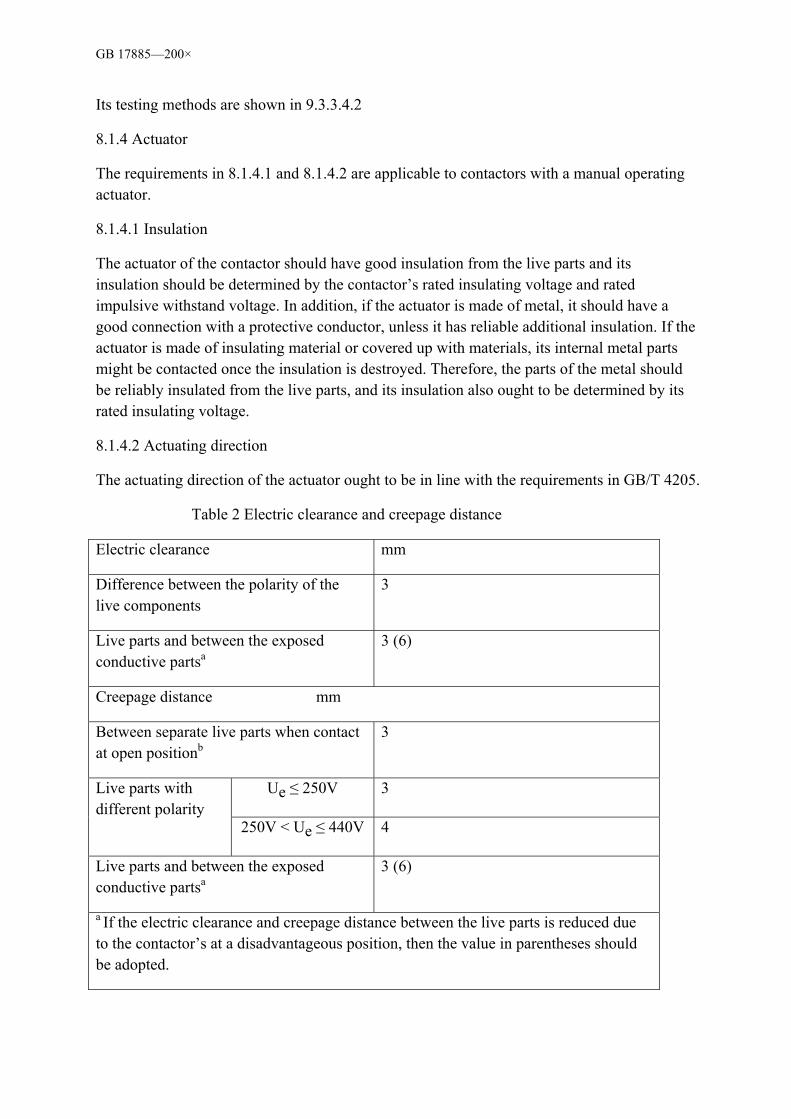
8.1.3 Electric clearance and creepage distance
a) For the contactors, which has been provided for Uimp (see 5.3.1.3) by the manufacture, the minimal electric clearance is shown in Table 19 and the minimal creepage distance is shown in Table 20.
The two are relevant to the Ui.
Its testing methods are shown in 9.3.3.4.1.
b) For the contactors, which has not been provided with Uimp by the manufacture, its minimal electric clearance and creepage distance should not be less than the required values in Table 2, when the contactors are installed for normal use.
The testing methods are shown in 9.3.3.4.2.
c) For SELV circuit, minimal clearance or creepage distance are still under consideration.
The requirements of the dielectric properties are shown in 8.2.3.
Note 1: The different live parts of the contactors, which can be installed close to each other, should be provided with enough clearance.
Note 2: For the contactors whose control circuit is to be connected to ultra-low power supply, when the voltage provided by the main circuit is greater than the ultra-low security voltage, the electric clearance and creepage distance of the control circuit and the main circuit should be greater than or equal to 6mm.
GB 17885—200×
Its testing methods are shown in 9.3.3.4.2
8.1.4 Actuator
The requirements in 8.1.4.1 and 8.1.4.2 are applicable to contactors with a manual operating actuator.
8.1.4.1 Insulation
The actuator of the contactor should have good insulation from the live parts and its insulation should be determined by the contactor’s rated insulating voltage and rated impulsive withstand voltage. In addition, if the actuator is made of metal, it should have a good connection with a protective conductor, unless it has reliable additional insulation. If the actuator is made of insulating material or covered up with materials, its internal metal parts might be contacted once the insulation is destroyed. Therefore, the parts of the metal should be reliably insulated from the live parts, and its insulation also ought to be determined by its rated insulating voltage.
8.1.4.2 Actuating direction
The actuating direction of the actuator ought to be in line with the requirements in GB/T 4205.
Table 2 Electric clearance and creepage distance
Electric clearance mm
Difference between the polarity of the live components
3
Live parts and between the exposed conductive partsa
3 (6)
Creepage distance mm
Between separate live parts when contact at open positionb
3
Ue ≤ 250V 3 Live parts with different polarity
250V < Ue ≤ 440V 4
Live parts and between the exposed conductive partsa
3 (6)
a If the electric clearance and creepage distance between the live parts is reduced due to the contactor’s at a disadvantageous position, then the value in parentheses should be adopted.
GB 17885—200×
b Not applicable for auxiliary and control contactors.
8.1.4.3 Installations
The actuators which are installed at movable panels or open doors should be properly linked up with the associated parts, when the control panel was back in place or when the door is closed.
8.1.5 The markings of open and closed positions
8.1.5.1 Installation instructions
When the contactor is marked with open and closed positions, these should be clearly marked. For enclosed contactors, this marking can either be seen or not from outside.
This can be marked by position indicator. (See 3.3.16)
If graphic symbols are used, “1” and “0” should be used to indicate contactor’s open or closed positions respectively.
The contactor operated by two buttons should be indicated by the red colour only when it is marked for breaking. Otherwise use symbol “0”.
No other buttons are allowed to use the red colour.
Any buttons, button-type indicator as well as the colour of the indicator should be in line with the provisions in GB/T 4205.
8.1.5.2 Actuators used for position indication
When the actuator is used to indicate the contactor position, it should automatically remain in the relevant position opposite the contactor. Therefore, the actuator should have a set of two different resting positions that correspond to the contactor. For auto-disconnecting, the actuator can have a third different position.
8.1.6 Terminals
8.1.6.1 Structural requirements
All the parts in contact and current loading parts of the terminals should be made from metal that has sufficient mechanical strength.
In order to ensure sustainable maintenance of the necessary contactor pressure, the terminals should use effective ways to connect wires, such as screws, springs and others, etc.
At the appropriate contact surface, the structure of the terminals should enable wire pressing without causing damage to the wires and terminals.
GB 17885—200×
The structure of the terminals should not allow the wires to move, or any movement should not affect the normal operation of the contactor or cause the insulating voltage to be reduced below the rated value.
The testing methods are shown in 9.2.4.2, 9.2.4.3, 9.2.4.4.
Note: North American countries have specific requirements regarding the terminals or markings that are suitable for aluminium conductors.
8.1.6.2 The ability to connect to wires
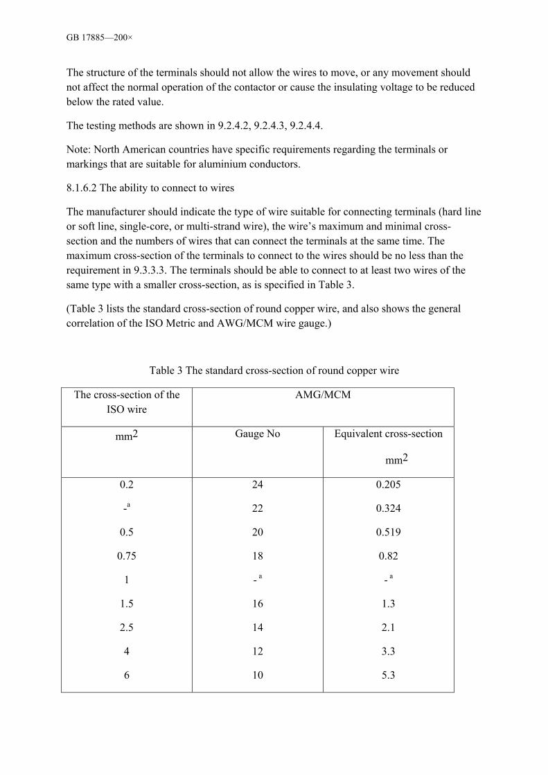
The manufacturer should indicate the type of wire suitable for connecting terminals (hard line or soft line, single-core, or multi-strand wire), the wire’s maximum and minimal cross-section and the numbers of wires that can connect the terminals at the same time. The maximum cross-section of the terminals to connect to the wires should be no less than the requirement in 9.3.3.3. The terminals should be able to connect to at least two wires of the same type with a smaller cross-section, as is specified in Table 3.
(Table 3 lists the standard cross-section of round copper wire, and also shows the general correlation of the ISO Metric and AWG/MCM wire gauge.)
Table 3 The standard cross-section of round copper wire
The cross-section of the ISO wire
AMG/MCM
mm2 Gauge No Equivalent cross-section
mm2
0.2
-a
0.5
0.75
1
1.5
2.5
4
6
24
22
20
18
- a
16
14
12
10
0.205
0.324
0.519
0.82
- a
1.3
2.1
3.3
5.3
GB 17885—200×
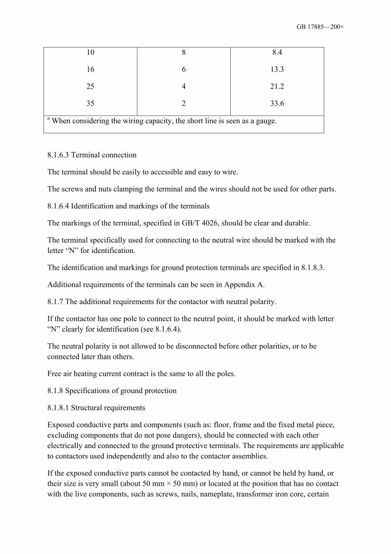
10
16
25
35
8
6
4
2
8.4
13.3
21.2
33.6
a When considering the wiring capacity, the short line is seen as a gauge.
8.1.6.3 Terminal connection
The terminal should be easily to accessible and easy to wire.
The screws and nuts clamping the terminal and the wires should not be used for other parts.
8.1.6.4 Identification and markings of the terminals
The markings of the terminal, specified in GB/T 4026, should be clear and durable.
The terminal specifically used for connecting to the neutral wire should be marked with the letter “N” for identification.
The identification and markings for ground protection terminals are specified in 8.1.8.3.
Additional requirements of the terminals can be seen in Appendix A.
8.1.7 The additional requirements for the contactor with neutral polarity.
If the contactor has one pole to connect to the neutral point, it should be marked with letter “N” clearly for identification (see 8.1.6.4).
The neutral polarity is not allowed to be disconnected before other polarities, or to be connected later than others.
Free air heating current contract is the same to all the poles.
8.1.8 Specifications of ground protection
8.1.8.1 Structural requirements
Exposed conductive parts and components (such as: floor, frame and the fixed metal piece, excluding components that do not pose dangers), should be connected with each other electrically and connected to the ground protective terminals. The requirements are applicable to contactors used independently and also to the contactor assemblies.
If the exposed conductive parts cannot be contacted by hand, or cannot be held by hand, or their size is very small (about 50 mm × 50 mm) or located at the position that has no contact with the live components, such as screws, nails, nameplate, transformer iron core, certain

GB 17885—200×
parts of electromagnet and release parts, they are considered to pose no dangers regardless of their size.
8.1.8.2 Ground protective terminals
Protective terminals should be easily accessible, easy to wire and can remain connected to the electrode or ground even when the cover and any other removable parts are removed.
Protective terminals should have the appropriate anti-wearing protection.
For the contactors that are equipped with conductive frames and housing, measures must be taken to ensure that there still exists electrical continuity between the exposed conductive parts of the contactors and metal sheath.
Protective terminals cannot be used for other purposes. Only when it is connected to PEN (see in 3.1.12) can the terminal of PEN not only used for protective grounding, but also used as neutral wire terminal.
8.1.8.3 The markings and identification of the protective terminal
The markings for protective terminal should be durable and clear.
According to the provisions in GB/T 4026-2004 5.3, protective terminals should be identified by adopting colour markings (green-yellow markings) or symbol PEN or markings on the devices with graphic symbols under the condition of PEN.
Symbol as specified in GB/T 5465.2:
Protective grounding
Note: The former recommended symbol should gradually be replaced by the symbol above.
8.1.9 Housing
The following requirements are only applicable to housings used together with the contactors.
8.1.9.1 Design
The housing should be designed in such a way that when open or other protective parts having been removed, all parts for installation and maintenance are easy to access.
In order to enable the external wires enter the housing and to ensure a good connection, there must be enough space left in the housing.
The fixed part of the metal housing and the other exposed conductive parts should be electrically connected and even connected to the ground terminal, ensure a good ground connection or connection to the ground protective conductor. When the installations of the

GB 17885—200×
housing’s removable metal parts are in place, they should not be installed from the ground terminals and the removable parts are fixed firmly at a fixed place in the housing in order to prevent the accidental release or loss due to the contactor’s operation or vibration.
The housing, which has housing protection degree IP1 to IP4 (includingIP4), should be left with enough space to set scuppers. The detailed requirements can be referred to in GB/T 14048.1.
The housing should have appropriate mechanical strength. (see 8.1.11)
It is not allowed to open the housing or remove any parts of the housing without the correct tools.
The required housing is considered as an irremovable part.
Removal of buttons from the external housing is is not permitted.
8.1.9.2 Insulation
In order to prevent the metal housing from accidentally contacting with the live parts, some or all of the housing should be lined with insulating materials, which should be firmly fixed in the housing.
Visually inspect whether it is in line with the requirements.
8.1.10 The housing’s protective degree of the enclosed contactors
The requirements and testing methods of the housing’s protective degree of the enclosed contactors are shown in appendix C in GB 14048.1-2006
8.1.11 Impact resistance performance
The external parts of the closed and semi-closed contactor and parts of the non-closed contactors should be able to withstand the expected impact under normal conditions.
The testing methods are shown in 9.2.5.
8.1.12 Durability of the markings
The markings of the contactors should be clear, easy to identify and durable.
Testing methods are shown in 9.2.6
8.2 Performance requirements
8.2.1 Operating conditions
8.2.1.1 The general requirements of the operating conditions
The contactors ought to be operated according to the provisions of the manufacturer.
GB 17885—200×
In operation, every polarity of the multi-contractors should be connected and disconnted at the same time (See 8.1.7 for neutral)
8.2.1.2 Actuating range
The contactor can actuate at any value between 85% and 110% of the rated control power voltage Us. In this range, 110% Us is the upper limit and 85% Us is the lower limit.
Between 75% and 20%, the contactors should release and break completely. In this range, 20 Us is the upper limit and 75% Us is the lower limit.
The pick-up limits are determined at the ambient temperature of +40 and when coils achieve constant temperature rise under 100% Us.
The release limits are determined at the ambient temperature of -5 and when the coil is cold. This value can be acquired from the conversion of the value obtained at room temperature.
The above values are applicable to AV voltage with specified frequency.
8.2.2 Temperature rise
In accordance with the requirements in 8.2.2, 8.2.2.1, 8.2.2.2 and 8.2.2.3, it is applied to clean and new contactors.
When the contactor conducts tests according to the provisions in 9.3.3.3, the allowed temperature rise of every part should not exceed the limit value provided in 8.2.2.1, 8.2.2.2 and Table 6.
Note: Under normal usage condition, the temperature rise might be different from the testing value, which is determined by the installation condition and the size of the conductors connected.
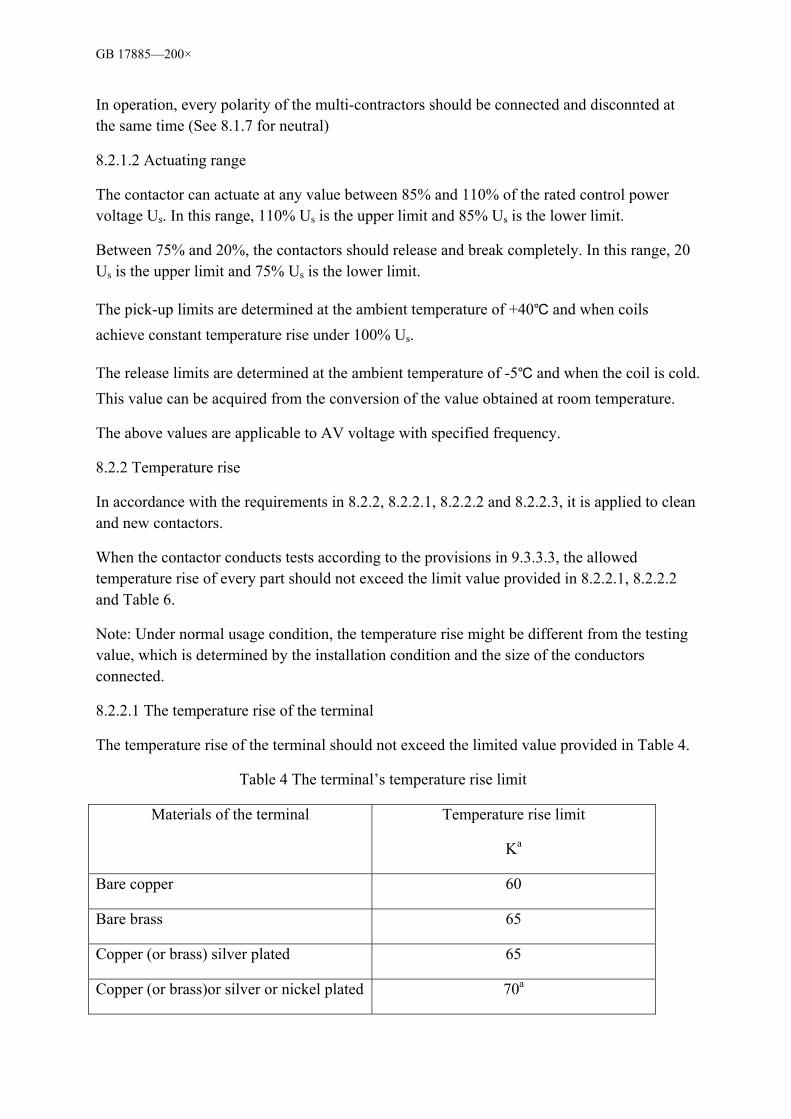
8.2.2.1 The temperature rise of the terminal
The temperature rise of the terminal should not exceed the limited value provided in Table 4.
Table 4 The terminal’s temperature rise limit
Materials of the terminal Temperature rise limit
Ka
Bare copper 60
Bare brass 65
Copper (or brass) silver plated 65
Copper (or brass)or silver or nickel plated 70a
GB 17885—200×
Other metals b
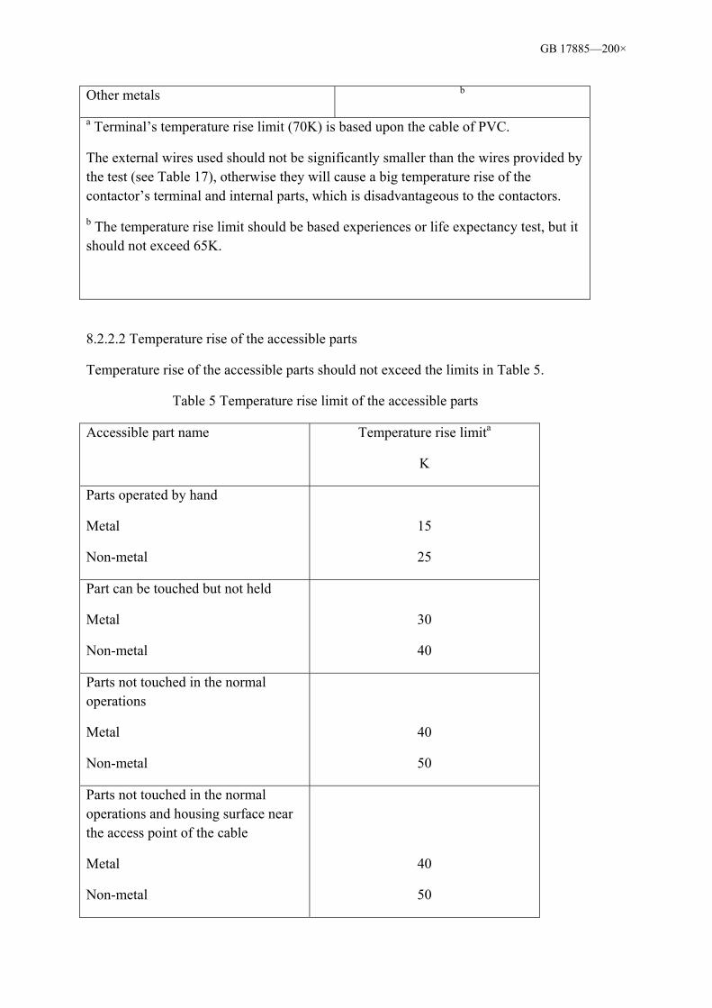
a Terminal’s temperature rise limit (70K) is based upon the cable of PVC.
The external wires used should not be significantly smaller than the wires provided by the test (see Table 17), otherwise they will cause a big temperature rise of the contactor’s terminal and internal parts, which is disadvantageous to the contactors.
b The temperature rise limit should be based experiences or life expectancy test, but it should not exceed 65K.
8.2.2.2 Temperature rise of the accessible parts
Temperature rise of the accessible parts should not exceed the limits in Table 5.
Table 5 Temperature rise limit of the accessible parts
Accessible part name Temperature rise limita
K
Parts operated by hand
Metal
Non-metal
15
25
Part can be touched but not held
Metal
Non-metal
30
40
Parts not touched in the normal operations
Metal
Non-metal
40
50
Parts not touched in the normal operations and housing surface near the access point of the cable
Metal
Non-metal
40
50
GB 17885—200×
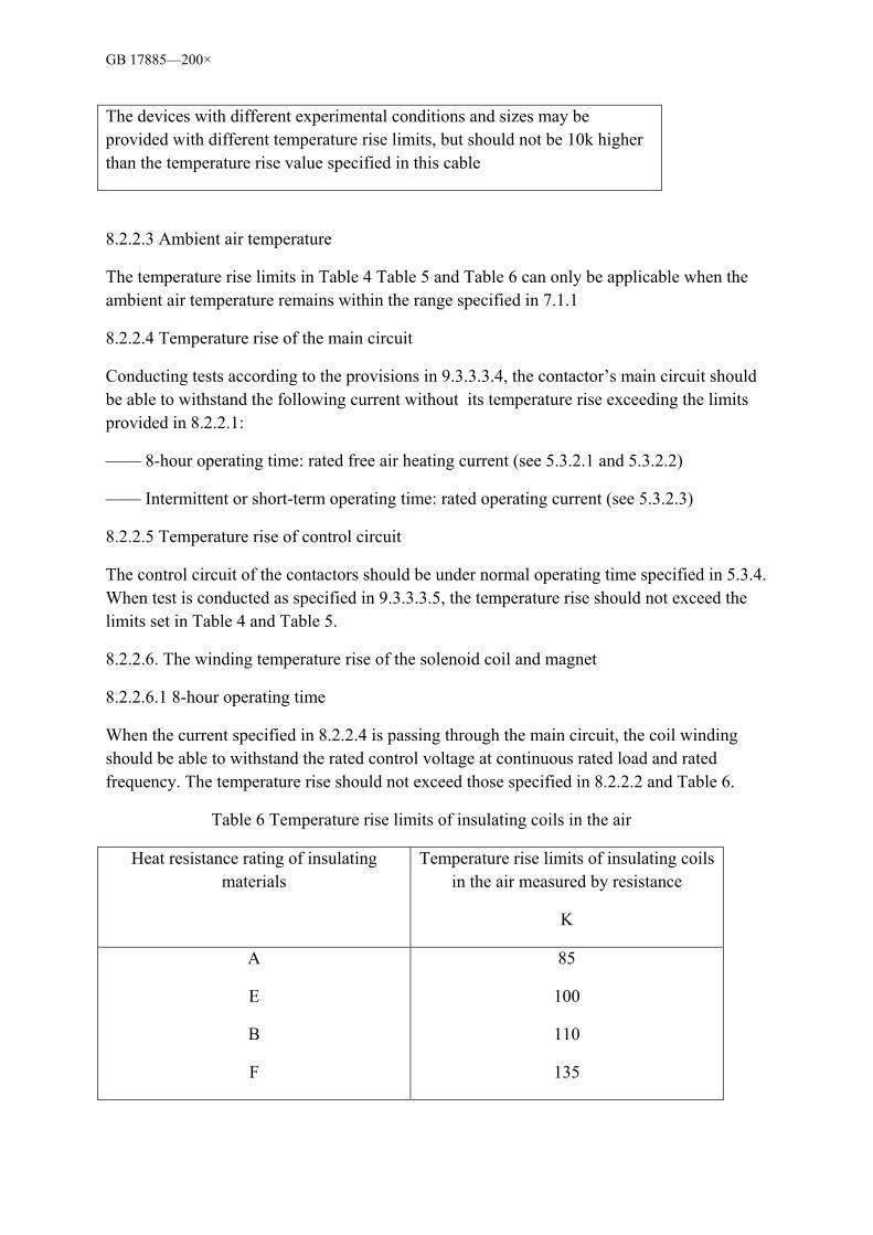
The devices with different experimental conditions and sizes may be provided with different temperature rise limits, but should not be 10k higher than the temperature rise value specified in this cable
8.2.2.3 Ambient air temperature
The temperature rise limits in Table 4 Table 5 and Table 6 can only be applicable when the ambient air temperature remains within the range specified in 7.1.1
8.2.2.4 Temperature rise of the main circuit
Conducting tests according to the provisions in 9.3.3.3.4, the contactor’s main circuit should be able to withstand the following current without its temperature rise exceeding the limits provided in 8.2.2.1:
—— 8-hour operating time: rated free air heating current (see 5.3.2.1 and 5.3.2.2)
—— Intermittent or short-term operating time: rated operating current (see 5.3.2.3)
8.2.2.5 Temperature rise of control circuit
The control circuit of the contactors should be under normal operating time specified in 5.3.4. When test is conducted as specified in 9.3.3.3.5, the temperature rise should not exceed the limits set in Table 4 and Table 5.
8.2.2.6. The winding temperature rise of the solenoid coil and magnet
8.2.2.6.1 8-hour operating time
When the current specified in 8.2.2.4 is passing through the main circuit, the coil winding should be able to withstand the rated control voltage at continuous rated load and rated frequency. The temperature rise should not exceed those specified in 8.2.2.2 and Table 6.
Table 6 Temperature rise limits of insulating coils in the air
Heat resistance rating of insulating materials
Temperature rise limits of insulating coils in the air measured by resistance
K
A
E
B
F
85
100
110
135

GB 17885—200×
H 100
Note 1: The degree 2 in GB/T 11021-2007 is taken as the insulating degree
Note 2: The temperature rise limits in Table 6 and 8.2.2.2 is only applicable when the ambient air temperature remains between -5~+40
8.2.2.6.2 Intermittent operating time
When there is no current passing the main circuit and when it is operated by the specified intermittent operating time in Table 7, for coil winding under the rated frequency and rated control voltage, its temperature rise should not exceed the limits specified in 8.2.2.2 and Table 6.
8.2.2.6.3 Special operating time (short-term and cycle operating time)
Test with special operating time should be conducted under the strictest operating conditions and its rated value is provided by the manufacturer.
8.2.2.7 Temperature rise of the auxiliary circuit
The contactor’s auxiliary circuit (including auxiliary switch) should be able to withstand the free air heating current. When tests are conducted according to the provisions in 9.3.3.3.7, the temperature rise should not exceed the limits specified in Table 4 and Table 5.
Note: If the auxiliary circuit is a part of the contactor, its testing can be conducted together with the main circuit, but actual operating current should be applied.
Table 7 The operating conditions of the intermittent operating time
The intermittent operating time classification
Each operating cycle
s
Coil charging time
1
3
12
30
300
1200
3600
1200
300
120
12
3
Select as per load factor.
GB 17885—200×
8.2.2.8 The temperature rise of other parts
The temperature rise of other parts should not affect their adjacent current loading parts, especially for insulating materials. The factory should show that they are in accordance with the insulating materials heat resistance category (identified by the methods in GB/T 11026.1), or as specified in GB/T 11021.
8.2.3 Dielectric properties
8.2.3.1 General principles
a) If the factory has specified the Uimp value (see 5.3.1.3), 8.2.3.2 or 8.2.3.1c), test methods are shown in 9.3.3.4.1,
Note: The requirements of overvoltage category II (see appendix F) should be met, unless specified otherwise.
b) If the manufacturer does not specify the Uimp value, the provisions in 9.3.3.4.2 should be used.
c) Specified contactors in SELV circuit should be able to withstand power frequency test voltage of 4000V with an application time of 1 min applied on live parts and components of any other circuit in SELV circuit.
d) After the test, check the condition of the contactor. Carry out the power frequency voltage withstand test for 1 min, as specified in 9.3.3.5.4b) and 9.3.3.6.2.
8.2.3.2 Dielectric performance requirements
a) The following requirements, which are based upon the principles in GB/T 16935.1-1997, provide the possibility for the insulation coordination of the contactors and devices.
b) Contactors should withstand the dielectric test required in 9.3.3.4.1.
c) Contactors shall withstand rated impulsive withstand voltage (see 5.3.1.3) corresponding to the overvoltage categories specified in the appendix F.
d) The rated impulsive withstand voltage corresponding to a specified rated operating voltage (see 5.3.1.1 Note 1, 2) , should be no less than the nominal voltage of the power system the contact is in and rated impulsive withstand voltage specified in appendix F.
8.2.3.2.1 The main circuit of shock pressure
a) The creepage between the live parts and ground and that between the poles should be able to withstand the rated impulsive withstand test voltage in Table 18 (see 9.3.3.4.1).
b) Contactors related solid insulations in a) shall withstand the impulsive withstand voltage specified in a).
8.2.3.2.2 Impulsive voltage of the auxiliary circuit and control circuit
GB 17885—200×
a) Auxiliary circuit and control circuit, which connected directly with the main circuit under the rated operating voltage, should meet the requirements in 8.2.3.2.1a) and b) .
b) Auxiliary circuit and control circuit, which have no direct connection with the main circuit, can be different in its ability to withstand the voltage of the main circuit. These circuit (AC or DC) and related creepage of solid insulation should be able to withstand the corresponding voltage required in Appendix F.
8.2.3.2.3 Clearance
Clearance should enable the contact to withstand rated impulsive withstand voltage specified in 8.2.3.2.1 and 8.2.3.2.2.
Contactors should adopt the minimum clearance provided in Table 19, circumstance B (for uniform electric field, see 3.5.31) and conduct tests as per 9.3.3.4.1f). If it is more than the minimum clearance in Table 19 circumstance A (non-uniform electric field), it is not necessary to conduct the rated impulsive withstand voltage test.
Clearance measurements are shown in appendix E.
8.2.3.2.4 Creepage distance
a) Determine the distance
For contactors of pollution level 3 and 4, although minimum clearance allowed can be less than circumstance A specified in 8.2.3.2.3, in order to reduce the disruptive discharge risks, creepage distance should be no less than the circumstance A specified in 8.2.3.2.3.
The creepage distance measurements are shown in appendix E.
Creepage distance should correspond to the relevant product standards or the pollution level specified in 7.1.3.2, and correspond to the relevant categories of the rated voltage or actual operating voltage of insulation materials in table 20.
Insultation materials can be divided into the following four categories according to their CTI values:
Insulation materials group I: 600≤CTI
Insulation materials group II: 400≤CTI < 600
Insulation materials group IIIa: 175≤CTI < 400
Insulation materials group IIIIb: 100≤CTI < 175
Note 1: The value of CTI is obtained by the methods specified in GB/T 4207, for insulation materials.
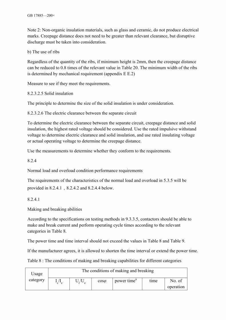
GB 17885—200×
Note 2: Non-organic insulation materials, such as glass and ceramic, do not produce electrical marks. Creepage distance does not need to be greater than relevant clearance, but disruptive discharge must be taken into consideration.
b) The use of ribs
Regardless of the quantity of the ribs, if minimum height is 2mm, then the creepage distance can be reduced to 0.8 times of the relevant value in Table 20. The minimum width of the ribs is determined by mechanical requirement (appendix E E.2)
Measure to see if they meet the requirements.
8.2.3.2.5 Solid insulation
The principle to determine the size of the solid insulation is under consideration.
8.2.3.2.6 The electric clearance between the separate circuit
To determine the electric clearance between the separate circuit, creepage distance and solid insulation, the highest rated voltage should be considered. Use the rated impulsive withstand voltage to determine electric clearance and solid insulation, and use rated insulating voltage or actual operating voltage to determine the creepage distance.
Use the measurements to determine whether they conform to the requirements.
8.2.4
Normal load and overload condition performance requirements
The requirements of the characteristics of the normal load and overload in 5.3.5 will be
provided in 8.2.4.1,8.2.4.2 and 8.2.4.4 below.
8.2.4.1
Making and breaking abilities
According to the specifications on testing methods in 9.3.3.5, contactors should be able to make and break current and perform operating cycle times according to the relevant categories in Table 8.
The power time and time interval should not exceed the values in Table 8 and Table 9.
If the manufacturer agrees, it is allowed to shorten the time interval or extend the power time.
Table 8 : The conditions of making and breaking capabilities for different categories
The conditions of making and breaking Usage
category Ic/Ie Ur/Ue cosφ power timea time No. of operation
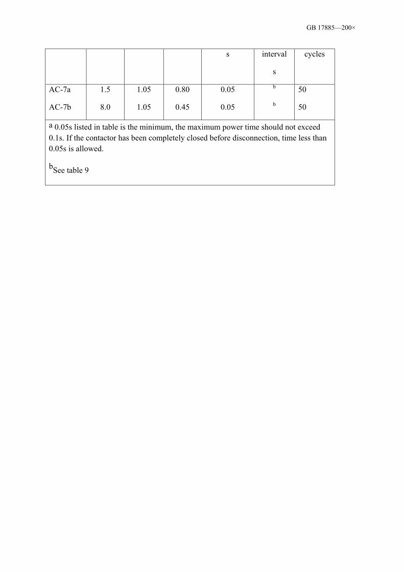
GB 17885—200×
s interval
s
cycles
AC-7a
AC-7b
1.5
8.0
1.05
1.05
0.80
0.45
0.05
0.05
b
b
50
50
a 0.05s listed in table is the minimum, the maximum power time should not exceed 0.1s. If the contactor has been completely closed before disconnection, time less than 0.05s is allowed.
bSee table 9

GB 17885—200×
Table 9 The correlation of breaking current and the interval time
Breaking current Ic
A
Interval time
s
Ic≤100
100 < Ic ≤ 200
200 < Ic ≤ 300
10
20
30
8.2.4.2 Rated operating performance
The test relevant to the operation performance of the contactors was used to verify the capabilities of the device on making, carrying and breaking the main current without any faults.
According to the provisions of the testing method in 9.3.3.6, contactors should be able to make and break the current and perform operating cycle times according to the categories in Table 10.
Table 10 Conditions of making and breaking capabilities for different categories
The conditions of making and breaking
Usage category
Ic/Ie Ur/Ue cosφ power timea
s
time interval
s
cycling times
AC-7a
AC-7b
1.0
d
1.05
c
0.80
0.45
0.05
0.05
b
b
30 000
30 000
a 0.05s listed in table is the minimum, the maximum power time should not exceed 0.1s. If the contactor has been completely closed before disconnection, time less than 0.05s is allowed;
b See table 9;
c To making operation Ur/Ue=1.0 to break operationUr/Ue=0.17;
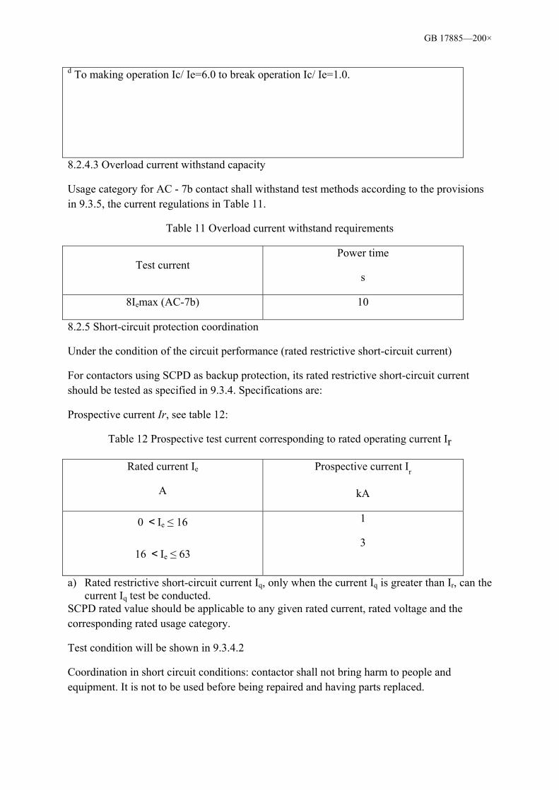
GB 17885—200×
d To making operation Ic/ Ie=6.0 to break operation Ic/ Ie=1.0.
8.2.4.3 Overload current withstand capacity
Usage category for AC - 7b contact shall withstand test methods according to the provisions in 9.3.5, the current regulations in Table 11.
Table 11 Overload current withstand requirements
Test current Power time
s
8Iemax (AC-7b) 10
8.2.5 Short-circuit protection coordination
Under the condition of the circuit performance (rated restrictive short-circuit current)
For contactors using SCPD as backup protection, its rated restrictive short-circuit current should be tested as specified in 9.3.4. Specifications are:
Prospective current Ir, see table 12:
Table 12 Prospective test current corresponding to rated operating current Ir
Rated current Ie
A
Prospective current Ir
kA
0 <Ie ≤ 16
16 <Ie ≤ 63
1
3
a) Rated restrictive short-circuit current Iq, only when the current Iq is greater than Ir, can the current Iq test be conducted.
SCPD rated value should be applicable to any given rated current, rated voltage and the corresponding rated usage category.
Test condition will be shown in 9.3.4.2
Coordination in short circuit conditions: contactor shall not bring harm to people and equipment. It is not to be used before being repaired and having parts replaced.

GB 17885—200×
Note: Using SCPD other than that recommended by the manufacturer may invalidate coordination.
8.3 Electromagnetic compatibility
8.3.1 Immunity
Performance of household and similar purpose electromechanical contactors in time of voltage change should be as specified in 8.2.1.2.
Contactor is not sensitive to the other electromagnetic interference under the condition of normal use described in 7.1.4 , so it is unnecessary to conduct the immunity test.
8.3.2 Emission
Household and similar purpose electromechanical contactors do not include a circuit, or only include simple diode rectifier circuit or components, such as resistors, or electrical components rheostat, (such as when using surge suppressor), etc
The electromagnetic interference only occurs in the making and breaking operation. The electromagnetic interference only lasts for milliseconds.
Until further research is carried out, the frequency and level are considered to be a part of the household and similar purpose electromechanical contactor normal electromagnetic environment. Therefore, there is no need for the electromagnetic emission test.
9 Test 9.1.1 Overview
The test should show whether contactors conform to the requirements of this standard. The testing procedures are shown in appendix B.
9.1.2 Model test
The model test is used to verify whether the contactor's design meets the requirements of this standard.
Experimental test items include the following:
a) Temperature rise test (see 9.3.3.3)
b) The dielectric properties test (see 9.3.3.4)
c) Rated making and breaking capability test (see 9.3.3.5)
d) Rated operating performance test (see 9.3.3.6)
e) Actuating and actuating scope testing (see 9.3.3.1 and 9.3.3.2)
f) Overload current withstand capacity test (see 9.3.5)

GB 17885—200×
g) Performance test under the short circuit condition (see 9.3.4)
h) Terminals of mechanical properties test (see 9.2.4)
i) Enclosed contactor housing protection degree test (see 9.2.3)
j) Aging performance test (see 9.2.1.1)
k) Humidity resistance test (see 9.2.1.2)
l) Heat resistance test (see 9.2.1.3)
m) Abnormal heat resistance and ignition risk test (see 9.2.1.4)
n) Rusting resistance test (see 9.2.1.5)
o) CTI test (see 9.2.1.6),
p) Screws and nut for installation and maintenance purpose (not used for terminals) performance test (see 9.2.2)
q) Impact resistance test (see 9.2.5)
r) Marking durability test (see 9.2.6)
Test procedures using the authentication type group.
Test procedures, and the quantity and result of the sample are specified in appendix B.
Unless specified otherwise, all tests (or programmed) should be conducted on the new and intact product.
Unless specified otherwise, the contactor tests are conducted in 25±10 ambience air temperature.
9.1.3 Routine testing
A routine test used to detect defects in material or function, and determine the normal function of the contactor. A routine test should be carried out on the contactors one by one before the products leave the factory. The test conditions should be the same or equal to the required model testing condition. (see 9.3.6.1)
The routine test of the contactors includes:
—— actuation and actuation scope (see 9.3.6.2)
—— dielectric properties (see 9.3.6.3)
9.1.4 Factory sampling test
This standard specifies the validation of the sampling test is the electrical clearance test.

GB 17885—200×
Test method (see 9.3.3.4.1f)
Sampling plan and test procedure are still under consideration.
9.2 Validation requirements
The validation of the relevant structural requirements can be referred to in 8.1, including:
——materials;
——contactor structure;
——enclosed device housing protective degree;
——mechanical performance of the terminals;
——the actuator;
——position indicator device (see 3.3.16).
9.2.1 Materials
9.2.1.1 Age resistance test
Contactor elastic components made from rubber, PVC or similar thermoplastic materials (e.g., sealing gasket, film and spiral cover mat etc), should be tested in the heating cabinet. The atmospheric elements and pressures should be the same as the ambient air in the cabinet, having the same natural ventilation and circulating. Tested components should be suspended freely in the cabinet.
The temperature in the cabinet should be 70±2.
Tested sample should be placed in the heating cabinet for 7d (168h). Electric heating is recommended for the cabinet. Natural circulation and ventilation can be achieved through aperture on walls. After 7 days, it should be removed from the heating cabinet and placed in
the relative humidity of 45%~55% in room temperature for less than 4 days (96 hours).
After the test, surface crack or shrinkage should not appear to have affected its further use, nor should it become sticky or greasy. The evaluation method is as follows:
Using the index finger wrapped with a piece of dry coarse cloth, applying 5N pressure on the sample. Indenting marks should show on cloth. The testing materials should not stick on the cloth. (5N pressure obtained are as follows: test materials will be put on one tray of the scale, in another tray the weight put on is equal to the weight of the testing material plus 500g, then use the index finger with a piece of dry cloth to apply pressure to the testing material so as to keep the scale in balance).
9.2.1.2 Damp resistance test
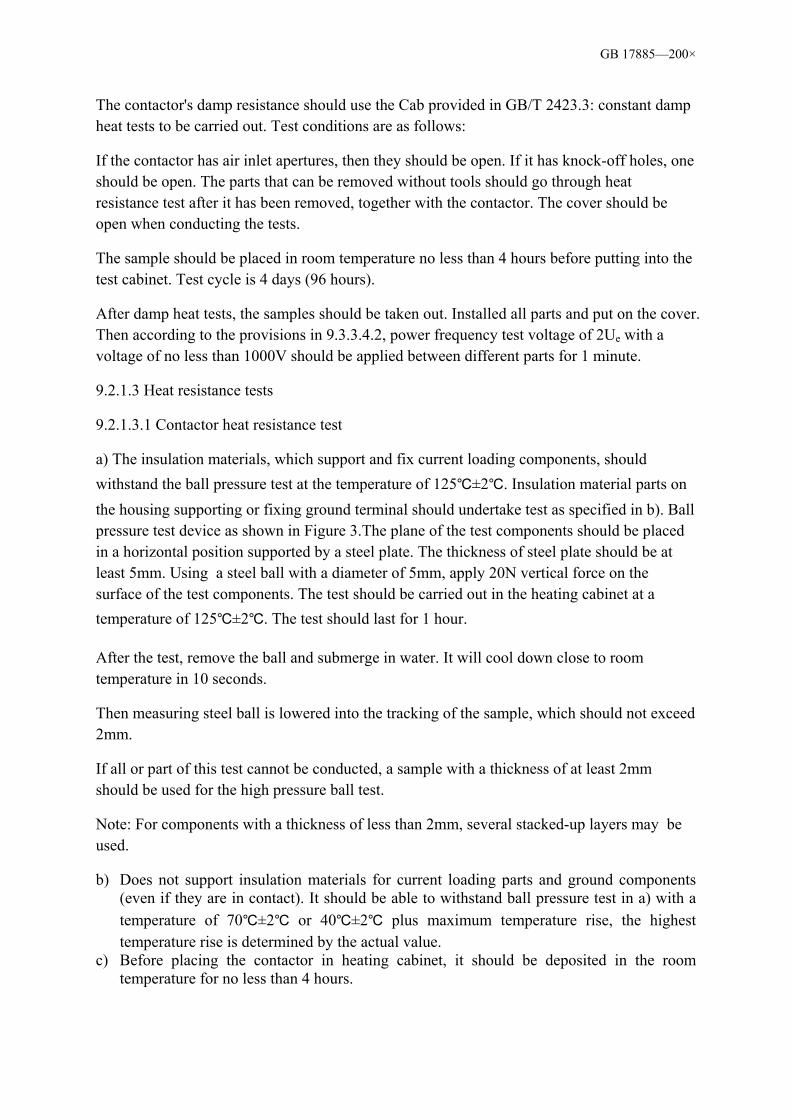
GB 17885—200×
The contactor's damp resistance should use the Cab provided in GB/T 2423.3: constant damp heat tests to be carried out. Test conditions are as follows:
If the contactor has air inlet apertures, then they should be open. If it has knock-off holes, one should be open. The parts that can be removed without tools should go through heat resistance test after it has been removed, together with the contactor. The cover should be open when conducting the tests.
The sample should be placed in room temperature no less than 4 hours before putting into the test cabinet. Test cycle is 4 days (96 hours).
After damp heat tests, the samples should be taken out. Installed all parts and put on the cover. Then according to the provisions in 9.3.3.4.2, power frequency test voltage of 2Ue with a voltage of no less than 1000V should be applied between different parts for 1 minute.
9.2.1.3 Heat resistance tests
9.2.1.3.1 Contactor heat resistance test
a) The insulation materials, which support and fix current loading components, should withstand the ball pressure test at the temperature of 125±2. Insulation material parts on the housing supporting or fixing ground terminal should undertake test as specified in b). Ball pressure test device as shown in Figure 3.The plane of the test components should be placed in a horizontal position supported by a steel plate. The thickness of steel plate should be at least 5mm. Using a steel ball with a diameter of 5mm, apply 20N vertical force on the surface of the test components. The test should be carried out in the heating cabinet at a temperature of 125±2. The test should last for 1 hour.
After the test, remove the ball and submerge in water. It will cool down close to room temperature in 10 seconds.
Then measuring steel ball is lowered into the tracking of the sample, which should not exceed 2mm.
If all or part of this test cannot be conducted, a sample with a thickness of at least 2mm should be used for the high pressure ball test.
Note: For components with a thickness of less than 2mm, several stacked-up layers may be used.
b) Does not support insulation materials for current loading parts and ground components (even if they are in contact). It should be able to withstand ball pressure test in a) with a temperature of 70±2 or 40±2 plus maximum temperature rise, the highest temperature rise is determined by the actual value.
c) Before placing the contactor in heating cabinet, it should be deposited in the room temperature for no less than 4 hours.

GB 17885—200×
The contactor should be in place for long enough to achieve thermal equilibrium and for not less than 1 hour. The temperature in the cabinet should be 100±2.
Then, the tested sample should be cooled close to room temperature.
Then a force of no more than 5N should be applied to the accessible housing surface using a test bar (see Figure 10). The test bar should not touch any of the powered parts of the contactor. Also check the markings on the contactor are still clear and legible.
9.2.1.3.2 Material heat resistance test
Sample thickness of the insulation material should be at least 2mm, and should withstand the requirement of the heat resistance test in (9.2.1.3.1 a) and (or) b)
Note: If reliable data can be obtained from the insulation material manufacturer or other reliable sources, which can prove that the insulation materials meet the above requirements of the heat resistance, then the test can be omitted.
9.2.1.4 Abnormal heat resistance and ignition risk test
9.2.1.4.1 Contactor component test
The validation of the abnormal heat resistance ignition risk test is the thermal effect produced by simulating heat source or glow wire. The glow wire test is conducted according to the provisions of GB/T 5169.10 and GB/T 5169.11 under the following conditions:
a) The insulating material components, which support or fix the loading parts, should adopt the glow wire top end temperature of 850. When conducting tests, ground conductor protection is not regarded as the current loading component.
b)The insulating material components, which do not support or fix the loading parts and ground components (even in contact), should adopt the glow wire top end temperature of 650.
9.2.1.4.2 Material test
Perform the following material sample test:
Note: If reliable data can be obtained from the insulation material manufacturer or other reliable sources, which can prove that the insulation materials meet the requirements of 8.1.1.4, then the test can be omitted.
a) Inflammable classification of GB/T test, 11020
b) HWI test (see appendix G).
9.2.1.5 Rusting resistance tests
GB 17885—200×
First, the tested black metal components should be submerged in cooling chemical agents (such as pure gasoline). Stir the diachronic for 10min to remove all oil stains. Then immerge the test components into 10% of ammonium chloride solution for 10 minutes. The solution temperature should be controlled at 20±5). Get rid of excess water drops on parts
(without drying). Place in the steam-filled container at a temperature of 20±5 for another
10 minutes. Then place in the heating cabinet at the temperature of 100± 5 for 10 minutes to dry. The surface should be free of rust. Rusty spots at the top and yellow rusty spots can be ignored.
For small springs and similar components and parts which are difficult to access, grease coating can be used to prevent corrosion. Only when the protective effect is in doubt should the test to be performed on them. There is no need to remove the grease stain on the surface before the test.
9.2.1.6 Compared to the index (electric mark determination CTI)
The test uses the regulation in GB/T 4207 to measure the insulation material’s CTI value and materials group.
The right parts may be removed from the contactor or conducted on the right materials with permission.
9.2.2 Screws and nut for installation and maintenance purpose (not used for terminals) performance test
Screw and nut should be tightened and loosened as below:
—— For use with insulating materials, screw thread and nut are tightened and loosened for 10 times.
—— For all other conditions, 5 times.
For use with insulating materials, the bolts and nuts should be screwed completely each time.
Appropriate screwdrivers and torque wrench should be used, according to the regulation in Table 13 or manufacturer. Bolt and nut should not be over-tightened.
For hexagonal slot bolts tightened with screwdrivers, when the torque values listed in column II and III are different, testing should be carried out twice. The steps are as follows: —— Use a wrench to apply the torque specified in column III —— Use a screwdriver to apply the torque specified in column II on new samples
If the value in column II is same to the value in column III, only the test using a screwdriver is needed.

GB 17885—200×
In the test, the screw should not get loose, nor should there be damage that might prevent the contactor functioning, such as damage to the screw, the slot, threaded screw head gasket, stirrup or damages to the housing and cover.
9.2.3 Enclosed contactor housing protection degree test
Relevant test procedures are shown in GB 1408.1-2006.
After protection degree II test has been carried out, 2Ue test with a voltage of no less than 1000V applied for 1 minute should be carried out as specified in 9.3.3.4.2.
9.2.4 Terminals of mechanical properties test
The following test is not applicable for aluminium terminals and terminals connected to the aluminium conductors.
9.2.4.1 The general conditions of the test
Unless specified otherwise, every test should be carried out on new and intact terminals. When round copper wire is used to conduct testing, it should be in accordance with IEC 60028.
9.2.4.2 Terminals mechanical strength test
The appropriate type of maximum cross-sectional area of conductor should be adopted for the tests. Each conductor should be connected and removed 5 times. For screw-type terminals, tightening torque should be 110% of the torque value provided Table 13 or as per manufacturer’s specification (whichever is greater) for test.
This test should performed on two terminals.
For hexagonal head screws tightened with screwdrivers, if the values in the column II and III in Table 13 are different, the test should be carried out twice.
Use the torque value in column III for the first test and then use the torque value in column II for the second test.
If the values in the column II and III are the same, then only the screwdriver test is needed.
A new conductor should be used each time the bolt or nut is loosened.
In the test, the screw should not get loose, nor should there be damage that might prevent the contactor functioning, such as damage to the screw, the slot, threaded screw head gasket, stirrup or damages to the housing and cover.
9.2.4.3 Conductor test for accidental loosening or damage (bending test)
This applies to prefabricated round copper wire terminals. Factory should specify the number of wires, sectional area and type (soft lines and/or hard line, thread and/or single core)

GB 17885—200×
Use 2 new terminals to perform the test below:
a) with minimum cross-section wire and the maximum number of connections allowed attached to terminals for the test
b) with the maximum cross-section wire and the maximum number of connections allowed attached to terminals for the test
c) with provisions of the maximum and minimum cross-section wire and the maximum number of connections allowed attached to terminals for the test
For terminals that can be connected with both soft and hard wire (single core and/or more thread), tests should performed on different groups of test samples.
For terminals that can be connected with both soft and hard lines at the same time (single core and/or more thread), tests should performed as specified in c) above.
Table 13 The tightening torque for screw-type terminal for the mechanical strength test
Threads diameter, Φmm Torque N·m
Standard values in metrics
Diameter range Ia IIb IIIc
2.5
3.0
-
3.5
4.0
4.5
5.0
6.0
8.0
10
Φ ≤2.8
2.8 < Φ≤3.0
3.0 < Φ≤3.2
3.2 < Φ≤3.6
3.6 < Φ≤4.1
4.1 < Φ≤4.7
4.7 < Φ≤5.3
5.3 < Φ≤6.0
6.0 < Φ≤8.0
8.0 < Φ≤10.0
0.2
0.25
0.3
0.4
0.7
0.8
0.8
1.2
2.5
-
0.4
0.5
0.6
0.8
1.2
1.8
2.0
2.5
3.5
4.0
0.4
0.5
0.6
0.8
1.2
1.8
2.0
3.0
6.0
10.0

GB 17885—200×
a Applicable to screw heads not extruding the hole (countersunk head) after tightening, and can’t be tightened by screwdriver due to the size
b Applicable to bolts and nuts tightened with a screwdriver.
c Applicable to bolts and nut tightened by a tool other than a screwdriver.
The test should be conducted on the appropriate test device. Connect the required number of the wires to the terminals. The length of test wire should be longer than the height specified in the Table 14 by 75mm. The tightening torque should be as specified in Table 13. Test equipments are as shown in Figure 4.
Each wire is under circular motion according to the following test procedures:
The end of wire should go through the hole busher on the binder plate. The plate is set at position H (see Table 14). Bend all other wires so that they will not get in the way of the test. Bushings should be installed together with wire, horizontally position on the plate. Bushings with a speed of 10 (r.p.m) ±2 (r.p.m) draw a circle with a diameter of 75mm on the surface around the linking piece. The distance between the terminal outlet and the surface of the bushing is height (H), with a tolerance of 13mm. Lubrication should be applied to bushings in order to prevent the insulation wire from bending, twisting or rotating. The mass provided in Table 14 should be applied to the end of the wires, while the test should continue rotating for 135 circles.
During testing, the wires should not emerge from the terminals nor be broken near the clamping point.
After bending test, wires used in the test should undergo a pull-out test as specified in 9.2.4.4.
Table 14 Test values of the round copper wire bending test and the pull–out test
Wire section
mm
Bushing aperturea
mm
Height H±13
mm
Quality
kg
Tension
N
0.2
-
6.4
6.4
260
260
0.3
0.3
10
20
0.5
0.75
6.4
6.4
260
260
0.3
0.4
30
30
1.0
1.5
6.4
6.4
260
260
0.4
0.4
35
40

GB 17885—200×
2.5
4.0
9.5
9.5
279
279
0.7
0.9
50
60
6.0
10
9.5
9.5
279
279
1.4
2.0
80
90
16
25
12.7
12.7
298
298
2.9
4.5
100
135
-
35
14.3
14.3
318
318
5.9
6.8
156
190
aIf it’s difficult for the hole (diameter specified in the table) to accommodate the wire, the next available larger aperture in the table can be used.
9.2.4.4 Round copper wire pull-out test
After the bending test in 9.2.4.3, then the tension provided in Table 14 should be applied to the bending test's wires in 9.2.4.3.
Wire clamping screw in the test should not be tightened again. Tension should be maintained for 1 minute. Tension should be applied gradually.
Wires should not get loose from the terminals during the test, or break while they are clamped.
9.2.4.5 Round copper wire of maximum cross-section access capability test
9.2.4.5.1 Test procedures
Table 15 provides the analogue gauge for the test. The cross-section of the gauge should be able to pass through the holes on the terminals and the gauge should be able to set into the terminals completely by its own weight (see note in table 15).
Table 15 Biggest wire section and corresponding gauges
Cross-sectional area Analogue gauge (see Figure 5)
Soft wire
mm
Hard wire (Single or multiple thread)
mm
Model no.
Diameters
a
mm
Width
b
mm
Tolerance of a and b
mm
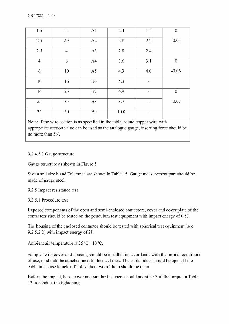
GB 17885—200×
1.5 1.5 A1 2.4 1.5
2.5 2.5 A2 2.8 2.2
2.5 4 A3 2.8 2.4
0
-0.05
4 6 A4 3.6 3.1
6 10 A5 4.3 4.0
10 16 B6 5.3 -
0
-0.06
16 25 B7 6.9 -
25 35 B8 8.7 -
35 50 B9 10.0 -
0
-0.07
Note: If the wire section is as specified in the table, round copper wire with appropriate section value can be used as the analogue gauge, inserting force should be no more than 5N.
9.2.4.5.2 Gauge structure
Gauge structure as shown in Figure 5
Size a and size b and Tolerance are shown in Table 15. Gauge measurement part should be made of gauge steel.
9.2.5 Impact resistance test
9.2.5.1 Procedure test
Exposed components of the open and semi-enclosed contactors, cover and cover plate of the contactors should be tested on the pendulum test equipment with impact energy of 0.5J.
The housing of the enclosed contactor should be tested with spherical test equipment (see 9.2.5.2.2) with impact energy of 2J.
Ambient air temperature is 25 ±10 .
Samples with cover and housing should be installed in accordance with the normal conditions of use, or should be attached next to the steel rack. The cable inlets should be open. If the cable inlets use knock-off holes, then two of them should be open.
Before the impact, base, cover and similar fasteners should adopt 2 / 3 of the torque in Table 13 to conduct the tightening.

GB 17885—200×
The sample should be subject to the impact 10 times, and the point of impact should be evenly distributed.
The impact should not fall on the knock-off hole area or fragile components (such as observation windows, indicators, etc.)
5 of the impacts should be conducted as follows:
a) For an embedded contactor, one impact falls on the centre and then one on each end of the installation slot. The other two impacts should fall on the midway of the previous two points of impact, best to be on the lateral edges.
b) For other types of contactors and install cabinets, one impact falls on the centre and then rotate the sample horizontally (close to but not more than 60º) and the impact falls to each side of the sample. The other two impacts should fall on the midway of the previous two points of impact, best to be on the lateral edges. The other two impacts are conducted the same way after rotating the sample 90º vertically.
After the test, the sample should not have any damage that will affect its further use. In particular, the cover should not be damaged leaving live parts are accessible. And there should be no damage that will affect the normal use of contactors, actuators and insulation pads or dividers. In case of doubt, external components such as housing and cover can be removed for inspection (but these components or the insulation pads should not be damaged).
Any cracks on the surface that will not reduce the creepage or clearance to below the specifications in Table 8.1.3, small dents or damages that have no obviously effects on electric shock protection can be ignored.
9.2.5.2 Test equipment
9.2.5.2.1 Pendulum test equipment (0.5J test)
Test equipments are shown as in Figure 6, Figure 7 and Figure 8.
Test equipments should be able to move the sample horizontally and rotate it along the axis perpendicular to the laminate and the vertical axis of the laminate can rotate along the perpendicularly axis.
The mass of impact components is 0.25kg. It should fall from the height of 0.20 m onto the exposed surface of the contactor installed as per normal usage, and the impact point should fall on the plane perpendicular to the pendulum.
The drop height should be the vertical distance between the testing point at the release of the pendulum and impact point. The testing point should be marked on the surface of the impact component.
The head of the impact component should have a semi-spherical surface with a radius of 10mm, which is made from polyamide material. The surface hardness is Rockwell hardness

GB 17885—200×
R100. Impact component was fixed under a steel pipe which has an external diameter of 9 mm, a wall thickness of 0.5 mm. The top of the pipe is fixed with a hinge so that it can only swing within a vertical plane.
The axis of the hinge should be 1000mm ±1 mm on top of the axis of the impact components
To determine the polyamide Rockwell hardness of the head of the impact components, the following should be adopted:
Diameter of the ball: 12.7 mm ± 0.002 5mm;
Starting load: 100N ± 2N;
Overload: 500N ± 2.5N.
For details, see ISO 2039-2. The plane-installed contactors should be installed on a laminate of 8mm thick, 175mmin size. The laminated should be fixed on a steel rack, which is also part of the installation rack (see Figure 7).The mass of the rack is 10kg±1kg. It is installed on a steel frame with a pivot. 9.2.5.2 .2 Ball test equipment (2J Test) As shown in Figure 9, the impact is produced by the drop or the swing of the ball. The steel ball has a diameter of 50mm and a weight of 0.5kg and is released from a height of 0.4 m. Height (H) is the vertical distance. When the cycloid is in vertical position, the steel ball is in contact with the test sample. The mass of the cycloid can be ignored when compared to the steel ball. The support should be one layer of oak board with two layers of laminates. The oak board has a thickness of about 19mm. The joint board should be placed on a concrete floor. Nonelastic supports of the same effect can also be used. 9.2.6 Marking durability test To test if the marking is as specified in 8.1.12, rub it with a wet cloth for 15 seconds, then with a gasoline-absorbent cloth for another 15 seconds. The gasoline used in the test is made from aliphatic hexane solution. The maximum volume ratio of aromatic series should be no more than 0.1%. The kauri buranol value is 29. The boiling point is 65, drying point is 69 and the specific gravity is 0.68g/cm3. After the test, the markings should be easy to identify. The nameplate should not move or warp. The markings should still be easy to read after all tests in the standard have been conducted. Markings made from stamping, mould pressing, ramming or carving do not need to undertake this test. 9.3 Verifying the performance requirements 9.3.1 Procedure test Procedure test and test sample see Appendix B. Sample should be able to withstand the procedure test. 9.3.1 General conditions of the test 9.3.2.1 General requirements All data of the contactors tested should be the same as in the figures and technical documents. Unless specified otherwise, the current type, frequency under AC conditions and phase of the test should be the same as expected. If stricter test data have been adopted to facilitate the test,

GB 17885—200×
eg. higher frequency has been adopted to reduce the test cycle, this must be agreed by the manufacturer. Contactors tested should be installed on the rack or supports of similar effects as specified in the manufacturer’s manual. Wiring should be done as per normal use. Environmental conditions for installation location should be as specified in 7.1. Enclosed contactors should be installed properly. Apertures closed in normal operation should be closed as well during the test. Enclosed contactor in single housing should be tested in the smallest housing as specified by the manufacturer. Note: Single housing is designed to be used by only one contactor. Otherwise, contactors should be tested in the atmosphere. Unless specified otherwise, when conducting making and breaking test and performance test under short-circuit conditions, metal mesh should be placed around the contactors at the possible yield points, as specified by the manufacturer. The distance between the contactor and the mesh should be noted in the rest report. Unless specified otherwise, repair and part replacement are not allowed. Prior to the test, contactors can be operated empty-loaded a few times. Unless specified otherwise in the standard, the operating system should be operated under expected usage conditions using the rated control parameters (eg. rated control voltage). 9.3.2.2 Test parameters 9.3.2.2.1 Test parameter value All tests should be conducted using the data provided in the standard and as per the rated parameters of manufacturer’s specifications. 9.3.2.2.2 Tolerance of the test parameters Unless specified otherwise in the standard, tolerance in the test should be as specified in Table 16. If agreed by manufacturer, the test can be conducted in stricter conditions.
Table 16 Tolerance of test parameter All tests Tests under empty load,
normal load & overload conditions
Tests under short-circuit conditions
Current: 0+5% Voltage: 0+5%
Power factor: ±0.05 Frequency: ±5%
Power factor: 0-5% Frequency: ±5%
Note 1: Specifications in table are not applicable to operating range. Note 2: As agreed by manufacturer and user, test conducted under 50 Hz can be considered as applicable to under 60 Hz conditions, vice versa.
9.3.2.2.3 Recovery voltage a) Power frequency recovery voltage For all breaking and short-circuit breaking capabilities test, power frequency recovery voltage should be 1.05 times of the rated operating voltage. Note 1: The power frequency recovery voltage is 1.05 times of the rated operating voltage. This has taken into consideration of the fluctuation of the power system voltage. Note 2: The applied voltage can be increased in the breaking test. However, without manufacture’s agreement, the predictive peak making current should not exceed the specified value. Note 3: If agreed by the manufacturer, the upper limit of power frequency recovery voltage can be increased (see 9.3.2.2.2). b) Transient recovery voltage Requirements see 9.3.3.5.3. 9.3.2.3 Test result evaluation
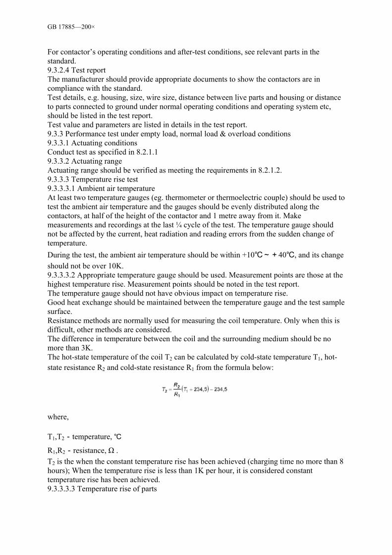
GB 17885—200×
For contactor’s operating conditions and after-test conditions, see relevant parts in the standard. 9.3.2.4 Test report The manufacturer should provide appropriate documents to show the contactors are in compliance with the standard. Test details, e.g. housing, size, wire size, distance between live parts and housing or distance to parts connected to ground under normal operating conditions and operating system etc, should be listed in the test report. Test value and parameters are listed in details in the test report. 9.3.3 Performance test under empty load, normal load & overload conditions 9.3.3.1 Actuating conditions Conduct test as specified in 8.2.1.1 9.3.3.2 Actuating range Actuating range should be verified as meeting the requirements in 8.2.1.2. 9.3.3.3 Temperature rise test 9.3.3.3.1 Ambient air temperature At least two temperature gauges (eg. thermometer or thermoelectric couple) should be used to test the ambient air temperature and the gauges should be evenly distributed along the contactors, at half of the height of the contactor and 1 metre away from it. Make measurements and recordings at the last ¼ cycle of the test. The temperature gauge should not be affected by the current, heat radiation and reading errors from the sudden change of temperature. During the test, the ambient air temperature should be within +10~+40, and its change should not be over 10K. 9.3.3.3.2 Appropriate temperature gauge should be used. Measurement points are those at the highest temperature rise. Measurement points should be noted in the test report. The temperature gauge should not have obvious impact on temperature rise. Good heat exchange should be maintained between the temperature gauge and the test sample surface. Resistance methods are normally used for measuring the coil temperature. Only when this is difficult, other methods are considered. The difference in temperature between the coil and the surrounding medium should be no more than 3K. The hot-state temperature of the coil T2 can be calculated by cold-state temperature T1, hot-state resistance R2 and cold-state resistance R1 from the formula below:
where,
T1,T2-temperature,
R1,R2-resistance, Ω . T2 is the when the constant temperature rise has been achieved (charging time no more than 8 hours); When the temperature rise is less than 1K per hour, it is considered constant temperature rise has been achieved. 9.3.3.3.3 Temperature rise of parts
GB 17885—200×
Temperature rise of parts is the temperature difference between the part temperature measured as specified in 9.3.3.3.2 and the ambience temperature measured as specified in 9.3.3.3.1. 9.3.3.3.4 Temperature rise test of the main circuit Contactors should be installed as per 9.3.2.1, and should not be affected by external abnormal heating and cooling. Main circuit should undertake load as specified in 8.2.2.4. Generally, the auxiliary circuits should apply the maximum rated operating current (see 5.6). Rated voltage should be applied to the control circuit. For contactors with housing, rated free-air heating current should be applied, and abnormal vents on the housing are not allowed. Contactors that can be used in different types of housings should be tested in the smallest housing as specified by the manufacturer or tested without housing. If tested without housing, manufacturer should provide a rated enclosed heating current value (see 5.3.2.2). For multi-phase current test, the current for each phase should be balanced with a tolerance of ±5%, and the average value should not be less than the test current specifies. Unless specified otherwise, the temperature rise test of the main circuit should be conducted under one or all rated free-air heating currents as per 5.3.2.1 and 5.3.2.2, and under any voltage. When the heating and the temperature rise between the main circuit, control circuit and auxiliary circuit affect each other, the temperature rise tests for these circuits should be conducted at the same time as per 9.3.3.3.4~9.3.3.3.7. If agreed by the manufacturer, multi-pole contactors should use parallel connection to apply single-phase current to conduct test. After the test, the temperature rise of all parts in the main circuit should not exceed the values in Table 4 and 5. The wires should be selected as follows:
a) The wires should adopt PVC insulating copper wire, with a cross-section as specified in Table 17, or smaller if agreed by manufacturer.
b) Wires should be placed in atmosphere, distance between wires is the distance between terminals.
c) When conducting single-phase or multi-phase temperature rise tests, the distance between terminals, or terminal to power supply or to star connecting point should be no less than 1 metre
9.3.3.3.5 Temperature rise test of the control circuit Temperature rise test of the control circuit should be conducted at the same time as the test in 9.3.3.3.4. Temperature rise test of the control circuit should adopt rated current, frequency and voltage. Temperature rise test of the control circuit should be carried on until a constant temperature rise is achieved. After the test, the temperature rise of all parts in the control circuit should not exceed the values in 8.2.2.5.

GB 17885—200×
Table 17 Copper leads for temperature rise tests
Lead section Test current range (I) A mm2 AWG/MCM
0< I≤8 8<I≤12
12< I≤15 15< I≤20 20< I≤25 25< I≤32 32< I≤50 50< I≤65 65< I≤85
1.0 1.5 2.5 2.5 4.0 6.0 10 16 25
18 16 14 12 10 10 8 6 4
Note 1: To facilitate test, conductors with lower test current can be used if agreed by manufacture. Note 2: Conduct size in metric measurement is listed in the table, together with the AWG/MCM change.
9.3.3.3.6 Temperature rise of electromagnetic coil Electromagnetic coils should be tested according to 8.2.2.6. Test should be carried on until a constant temperature rise has been achieved. Temperature rise should be measured when the main circuit and the electromagnetic coil have both achieved thermal equilibrium. Electromagnetic coils of the contactors should be tested as follows: a)For contactors to be used for 8 hours, only the test specified in 8.2.2.6.1 should be performed on its electromagnetic coils. The appropriate rated current will be applied in the main circuit in the test and the temperature rise is tested in 9.3.3.3.4. b)For contactors used in intermittent cycles, corresponding test specified in 8.2.2.6.2 should be performed on its electromagnetic coils. The main circuit is not powered in the test. c)For contacts used for special purpose (temporarily or in intermittent cycles), test specified in 8.2.2.6.3 should be performed on its electromagnetic coils. The main circuit is not powered in the test. After the test, temperature rise for all parts should not exceed the value specified in 8.2.2.6. 9.3.3.3.7 Temperature rise of auxiliary circuit The temperature rise test for auxiliary circuit should be performed in test 9.3.3.3.4. Test conditions are as specified in 9.3.3.3.5; however, they can be tested in any voltage. After the test, temperature rise for all parts should not exceed the value specified in 8.2.2.7. 9.3.3.4 Dielectric characteristics Tests should be performed as follows: a) If rated impulse withstand voltage Uimp (see 5.3.1.3) is specified by the manufacturer, the test is performed as specified in 9.3.3.4.1.
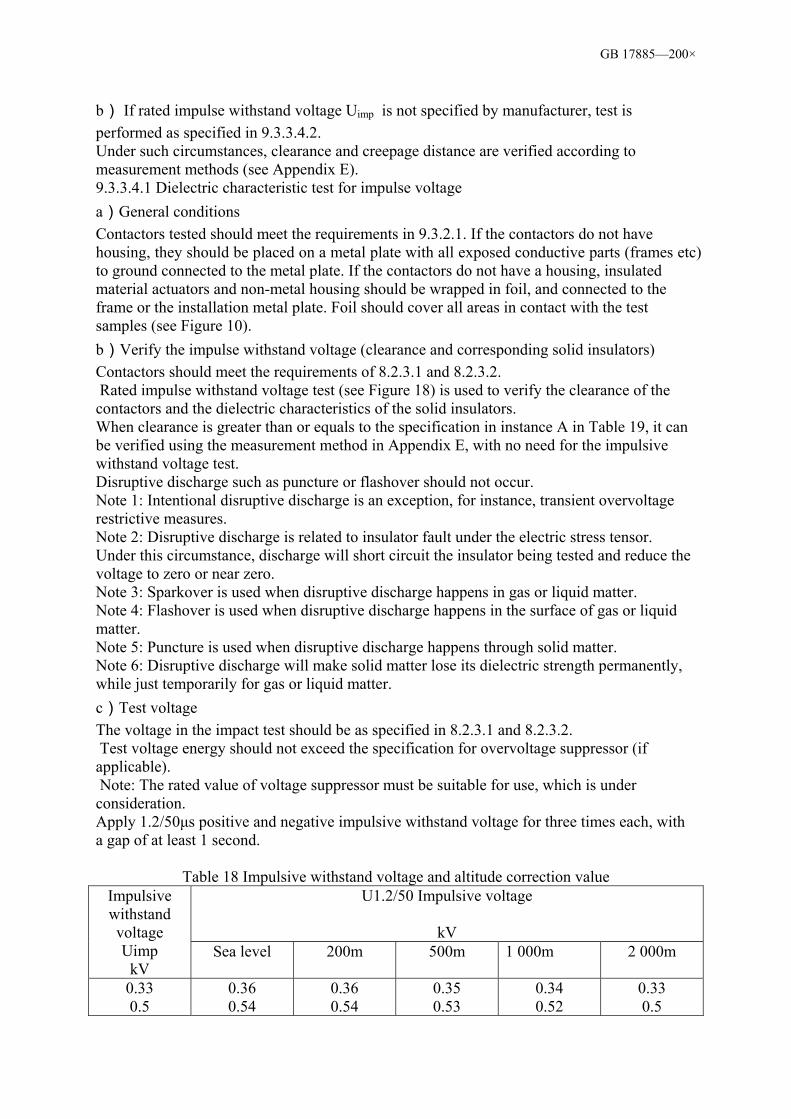
GB 17885—200×
b) If rated impulse withstand voltage Uimp is not specified by manufacturer, test is performed as specified in 9.3.3.4.2. Under such circumstances, clearance and creepage distance are verified according to measurement methods (see Appendix E). 9.3.3.4.1 Dielectric characteristic test for impulse voltage a)General conditions Contactors tested should meet the requirements in 9.3.2.1. If the contactors do not have housing, they should be placed on a metal plate with all exposed conductive parts (frames etc) to ground connected to the metal plate. If the contactors do not have a housing, insulated material actuators and non-metal housing should be wrapped in foil, and connected to the frame or the installation metal plate. Foil should cover all areas in contact with the test samples (see Figure 10). b)Verify the impulse withstand voltage (clearance and corresponding solid insulators) Contactors should meet the requirements of 8.2.3.1 and 8.2.3.2. Rated impulse withstand voltage test (see Figure 18) is used to verify the clearance of the contactors and the dielectric characteristics of the solid insulators. When clearance is greater than or equals to the specification in instance A in Table 19, it can be verified using the measurement method in Appendix E, with no need for the impulsive withstand voltage test. Disruptive discharge such as puncture or flashover should not occur. Note 1: Intentional disruptive discharge is an exception, for instance, transient overvoltage restrictive measures. Note 2: Disruptive discharge is related to insulator fault under the electric stress tensor. Under this circumstance, discharge will short circuit the insulator being tested and reduce the voltage to zero or near zero. Note 3: Sparkover is used when disruptive discharge happens in gas or liquid matter. Note 4: Flashover is used when disruptive discharge happens in the surface of gas or liquid matter. Note 5: Puncture is used when disruptive discharge happens through solid matter. Note 6: Disruptive discharge will make solid matter lose its dielectric strength permanently, while just temporarily for gas or liquid matter. c)Test voltage The voltage in the impact test should be as specified in 8.2.3.1 and 8.2.3.2. Test voltage energy should not exceed the specification for overvoltage suppressor (if applicable). Note: The rated value of voltage suppressor must be suitable for use, which is under consideration. Apply 1.2/50µs positive and negative impulsive withstand voltage for three times each, with a gap of at least 1 second.
Table 18 Impulsive withstand voltage and altitude correction value
U1.2/50 Impulsive voltage
kV
Impulsive withstand voltage Uimp
kV Sea level 200m 500m 1 000m 2 000m
0.33 0.5
0.36 0.54
0.36 0.54
0.35 0.53
0.34 0.52
0.33 0.5
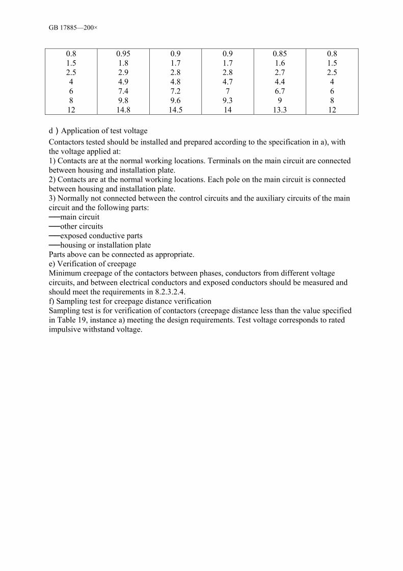
GB 17885—200×
0.8 1.5 2.5 4 6 8 12
0.95 1.8 2.9 4.9 7.4 9.8 14.8
0.9 1.7 2.8 4.8 7.2 9.6 14.5
0.9 1.7 2.8 4.7 7
9.3 14
0.85 1.6 2.7 4.4 6.7 9
13.3
0.8 1.5 2.5 4 6 8 12
d)Application of test voltage Contactors tested should be installed and prepared according to the specification in a), with the voltage applied at: 1) Contacts are at the normal working locations. Terminals on the main circuit are connected between housing and installation plate. 2) Contacts are at the normal working locations. Each pole on the main circuit is connected between housing and installation plate. 3) Normally not connected between the control circuits and the auxiliary circuits of the main circuit and the following parts: main circuit other circuits exposed conductive parts housing or installation plate Parts above can be connected as appropriate. e) Verification of creepage Minimum creepage of the contactors between phases, conductors from different voltage circuits, and between electrical conductors and exposed conductors should be measured and should meet the requirements in 8.2.3.2.4. f) Sampling test for creepage distance verification Sampling test is for verification of contactors (creepage distance less than the value specified in Table 19, instance a) meeting the design requirements. Test voltage corresponds to rated impulsive withstand voltage.

GB 17885—200×
Table 19 Minimum creepage distance in air Min. creepage
mm Instance A
Uneven electric field (see 3.5.32)
Instance B Even electric field (see 3.5.31)
Pollution degree Pollution degree
Impulsive withstand voltage Uimp
kV
1 2 3 4 1 2 3 4 0.33 0.01 0.01 0.5 0.04 0.04 0.8 0.1
0.2 0.1
0.2
1.5 0.5 0.5
0.8
0.3 0.3 2.5 1.5 1.5 1.5
1.6
0.6 0.6
0.8
4 3 3 3 3 1.2 1.2 1.2
1.6
6 5.5 5.5 5.5 5.5 2 2 2 2 8 8 8 8 8 3 3 3 3 12 14 14 14 14 4.5 4.5 4.5 4.5
Note: Minimum creepage distance in air is based on 1.2 /50µs impulsive voltage. Air pressure is 80kPa, equal to normal air pressure at 2,000m altitude.
Sampling test scheme and procedures are in consideration. Voltage should be applied as per specification in d), but foil does not need to be attached outside of actuator and housing. Disruptive discharge should not occur during the test. 9.3.3.4.2 Dielectric characteristic test for power frequency voltage a)Conditions for tested contactors The dielectric characteristic test should be performed on properly installed (including internal wiring), clean and dry contactors. If contactors use an insulated base, the metal parts should be tightened appropriately and be considered as part of the contactor frame. When the contactors are installed inside the insulated housing, the housing should be wrapped in foil and corrected to the frame. If the dielectric strength is related to the special insulator of the lead tap, the same lead tap or special insulator should be used in the test. b)Application of the test voltage If motor, meter, snap switch and semi-conductor devices have been installed, plus the withstand dielectric test voltage is less than the specification in c), they should be removed for the test as per the manufacturer’s instructions. 1) Power frequency withstand voltage for main circuit Connect the control circuits (which are not normally connected to the main circuits and the auxiliary circuits) to the main circuit. Time: 1 minute. When main contact is closed: ——between all terminals connected together and contactor frames ——each pole and all poles connected to the frame When main contact is open: ——between all terminals connected together and contactor frames ——between all incoming-line terminals and outgoing-line terminals connected
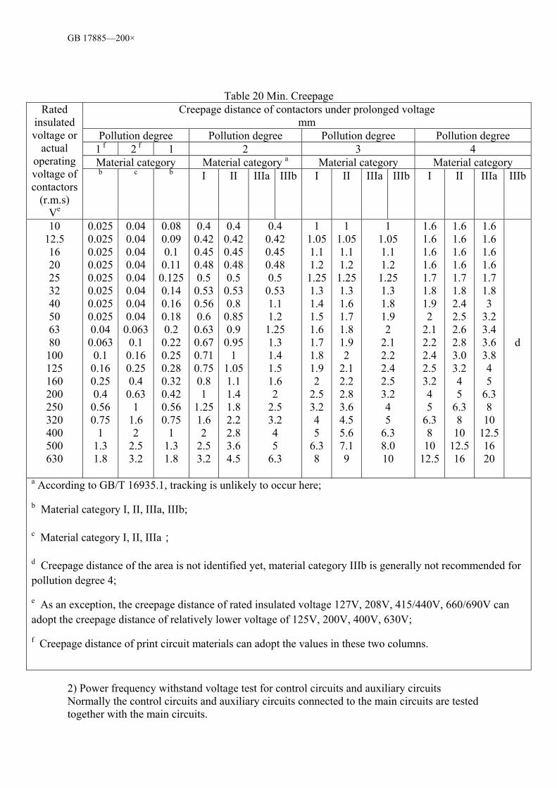
GB 17885—200×
Table 20 Min. Creepage Creepage distance of contactors under prolonged voltage
mm Pollution degree Pollution degree Pollution degree Pollution degree
1 f 2 f 1 2 3 4 Material category Material category a Material category Material category
Rated insulated voltage or
actual operating voltage of contactors
(r.m.s) Ve
b c b I II IIIa IIIb I II IIIa IIIb I II IIIa IIIb
10 12.5 16 20 25 32 40 50 63 80 100 125 160 200 250 320 400 500 630
0.025 0.025 0.025 0.025 0.025 0.025 0.025 0.025 0.04 0.063 0.1 0.16 0.25 0.4 0.56 0.75
1 1.3 1.8
0.04 0.04 0.04 0.04 0.04 0.04 0.04 0.04 0.063 0.1 0.16 0.25 0.4 0.63
1 1.6 2
2.5 3.2
0.08 0.09 0.1 0.11 0.125 0.14 0.16 0.18 0.2 0.22 0.25 0.28 0.32 0.42 0.56 0.75
1 1.3 1.8
0.4 0.42 0.45 0.48 0.5 0.53 0.56 0.6 0.63 0.67 0.71 0.75 0.8 1
1.25 1.6 2
2.5 3.2
0.4 0.420.450.480.5 0.530.8 0.850.9 0.95
1 1.051.1 1.4 1.8 2.2 2.8 3.6 4.5
0.4 0.42 0.45 0.48 0.5 0.53 1.1 1.2 1.25 1.3 1.4 1.5 1.6 2
2.5 3.2 4 5
6.3
1 1.051.1 1.2 1.251.3 1.4 1.5 1.6 1.7 1.8 1.9 2
2.5 3.2 4 5
6.3 8
1 1.051.1 1.2 1.251.3 1.6 1.7 1.8 1.9 2
2.1 2.2 2.8 3.6 4.5 5.6 7.1 9
1 1.05 1.1 1.2 1.25 1.3 1.8 1.9 2
2.1 2.2 2.4 2.5 3.2 4 5
6.3 8.0 10
1.6 1.6 1.6 1.6 1.7 1.8 1.9 2
2.1 2.2 2.4 2.5 3.2 4 5
6.3 8 10
12.5
1.6 1.6 1.6 1.6 1.7 1.8 2.4 2.5 2.6 2.8 3.0 3.2 4 5
6.3 8 10
12.516
1.6 1.6 1.6 1.6 1.7 1.8 3
3.2 3.4 3.6 3.8 4 5
6.3 8 10
12.516 20
d
a According to GB/T 16935.1, tracking is unlikely to occur here;
b Material category I, II, IIIa, IIIb;
c Material category I, II, IIIa;
d Creepage distance of the area is not identified yet, material category IIIb is generally not recommended for pollution degree 4;
e As an exception, the creepage distance of rated insulated voltage 127V, 208V, 415/440V, 660/690V can adopt the creepage distance of relatively lower voltage of 125V, 200V, 400V, 630V;
f Creepage distance of print circuit materials can adopt the values in these two columns.
2) Power frequency withstand voltage test for control circuits and auxiliary circuits Normally the control circuits and auxiliary circuits connected to the main circuits are tested together with the main circuits.
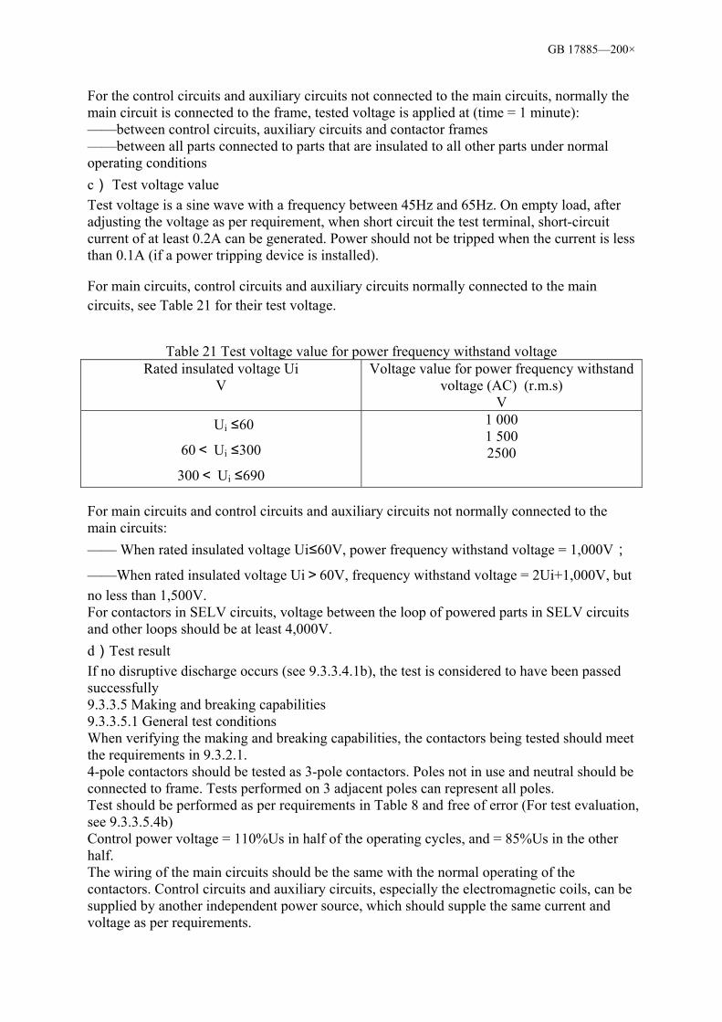
GB 17885—200×
For the control circuits and auxiliary circuits not connected to the main circuits, normally the main circuit is connected to the frame, tested voltage is applied at (time = 1 minute): ——between control circuits, auxiliary circuits and contactor frames ——between all parts connected to parts that are insulated to all other parts under normal operating conditions c) Test voltage value Test voltage is a sine wave with a frequency between 45Hz and 65Hz. On empty load, after adjusting the voltage as per requirement, when short circuit the test terminal, short-circuit current of at least 0.2A can be generated. Power should not be tripped when the current is less than 0.1A (if a power tripping device is installed). For main circuits, control circuits and auxiliary circuits normally connected to the main circuits, see Table 21 for their test voltage.
Table 21 Test voltage value for power frequency withstand voltage
Rated insulated voltage Ui V
Voltage value for power frequency withstand voltage (AC) (r.m.s)
V Ui ≤60
60< Ui ≤300
300< Ui ≤690
1 000 1 500 2500
For main circuits and control circuits and auxiliary circuits not normally connected to the main circuits: —— When rated insulated voltage Ui≤60V, power frequency withstand voltage = 1,000V;
——When rated insulated voltage Ui>60V, frequency withstand voltage = 2Ui+1,000V, but no less than 1,500V. For contactors in SELV circuits, voltage between the loop of powered parts in SELV circuits and other loops should be at least 4,000V. d)Test result If no disruptive discharge occurs (see 9.3.3.4.1b), the test is considered to have been passed successfully 9.3.3.5 Making and breaking capabilities 9.3.3.5.1 General test conditions When verifying the making and breaking capabilities, the contactors being tested should meet the requirements in 9.3.2.1. 4-pole contactors should be tested as 3-pole contactors. Poles not in use and neutral should be connected to frame. Tests performed on 3 adjacent poles can represent all poles. Test should be performed as per requirements in Table 8 and free of error (For test evaluation, see 9.3.3.5.4b) Control power voltage = 110%Us in half of the operating cycles, and = 85%Us in the other half. The wiring of the main circuits should be the same with the normal operating of the contactors. Control circuits and auxiliary circuits, especially the electromagnetic coils, can be supplied by another independent power source, which should supple the same current and voltage as per requirements.
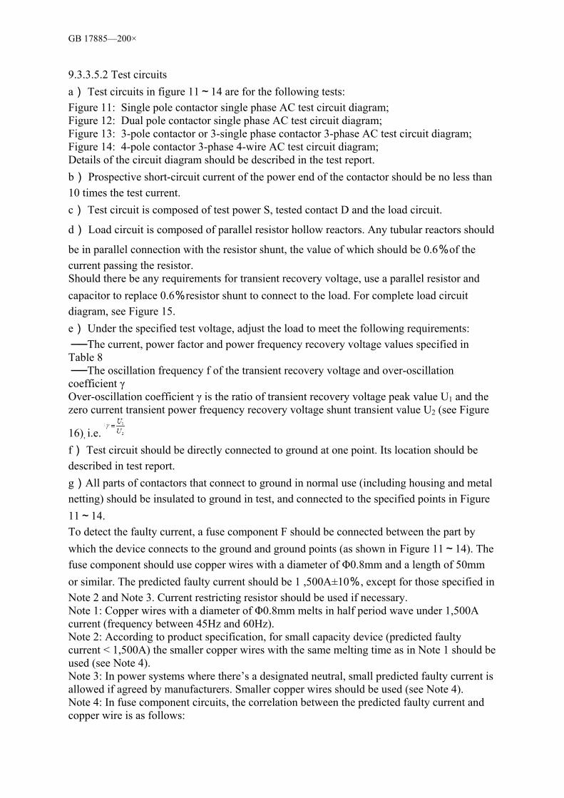
GB 17885—200×
9.3.3.5.2 Test circuits a) Test circuits in figure 11~14 are for the following tests: Figure 11: Single pole contactor single phase AC test circuit diagram; Figure 12: Dual pole contactor single phase AC test circuit diagram; Figure 13: 3-pole contactor or 3-single phase contactor 3-phase AC test circuit diagram; Figure 14: 4-pole contactor 3-phase 4-wire AC test circuit diagram; Details of the circuit diagram should be described in the test report. b) Prospective short-circuit current of the power end of the contactor should be no less than 10 times the test current. c) Test circuit is composed of test power S, tested contact D and the load circuit.
d) Load circuit is composed of parallel resistor hollow reactors. Any tubular reactors should
be in parallel connection with the resistor shunt, the value of which should be 0.6%of the current passing the resistor. Should there be any requirements for transient recovery voltage, use a parallel resistor and capacitor to replace 0.6%resistor shunt to connect to the load. For complete load circuit diagram, see Figure 15. e) Under the specified test voltage, adjust the load to meet the following requirements: The current, power factor and power frequency recovery voltage values specified in Table 8 The oscillation frequency f of the transient recovery voltage and over-oscillation coefficient γ Over-oscillation coefficient γ is the ratio of transient recovery voltage peak value U1 and the zero current transient power frequency recovery voltage shunt transient value U2 (see Figure
16), i.e. f) Test circuit should be directly connected to ground at one point. Its location should be described in test report. g)All parts of contactors that connect to ground in normal use (including housing and metal netting) should be insulated to ground in test, and connected to the specified points in Figure 11~14. To detect the faulty current, a fuse component F should be connected between the part by which the device connects to the ground and ground points (as shown in Figure 11~14). The fuse component should use copper wires with a diameter of Φ0.8mm and a length of 50mm or similar. The predicted faulty current should be 1 ,500A±10%, except for those specified in Note 2 and Note 3. Current restricting resistor should be used if necessary. Note 1: Copper wires with a diameter of Φ0.8mm melts in half period wave under 1,500A current (frequency between 45Hz and 60Hz). Note 2: According to product specification, for small capacity device (predicted faulty current < 1,500A) the smaller copper wires with the same melting time as in Note 1 should be used (see Note 4). Note 3: In power systems where there’s a designated neutral, small predicted faulty current is allowed if agreed by manufacturers. Smaller copper wires should be used (see Note 4). Note 4: In fuse component circuits, the correlation between the predicted faulty current and copper wire is as follows:
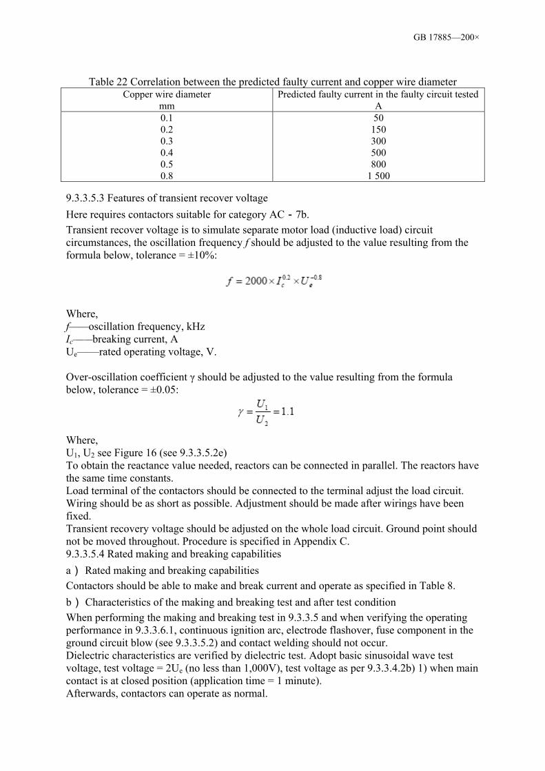
GB 17885—200×
Table 22 Correlation between the predicted faulty current and copper wire diameter
Copper wire diameter mm
Predicted faulty current in the faulty circuit tested A
0.1 0.2 0.3 0.4 0.5 0.8
50 150 300 500 800
1 500
9.3.3.5.3 Features of transient recover voltage Here requires contactors suitable for category AC-7b. Transient recover voltage is to simulate separate motor load (inductive load) circuit circumstances, the oscillation frequency f should be adjusted to the value resulting from the formula below, tolerance = ±10%:
Where, f——oscillation frequency, kHz Ic——breaking current, A Ue——rated operating voltage, V. Over-oscillation coefficient γ should be adjusted to the value resulting from the formula below, tolerance = ±0.05:
Where, U1, U2 see Figure 16 (see 9.3.3.5.2e) To obtain the reactance value needed, reactors can be connected in parallel. The reactors have the same time constants. Load terminal of the contactors should be connected to the terminal adjust the load circuit. Wiring should be as short as possible. Adjustment should be made after wirings have been fixed. Transient recovery voltage should be adjusted on the whole load circuit. Ground point should not be moved throughout. Procedure is specified in Appendix C. 9.3.3.5.4 Rated making and breaking capabilities a) Rated making and breaking capabilities Contactors should be able to make and break current and operate as specified in Table 8. b) Characteristics of the making and breaking test and after test condition When performing the making and breaking test in 9.3.3.5 and when verifying the operating performance in 9.3.3.6.1, continuous ignition arc, electrode flashover, fuse component in the ground circuit blow (see 9.3.3.5.2) and contact welding should not occur. Dielectric characteristics are verified by dielectric test. Adopt basic sinusoidal wave test voltage, test voltage = 2Ue (no less than 1,000V), test voltage as per 9.3.3.4.2b) 1) when main contact is at closed position (application time = 1 minute). Afterwards, contactors can operate as normal.

GB 17885—200×
9.3.3.6 Conventional performance test The conventional performance test is used to verify if contactors meet the requirements in Table 10. Wiring of the main circuit is the same as the wiring of the contactor when under normal operating condition. Test circuit as per 9.3.3.5.2, load as per 9.3.3.5.3. Control voltage = 100%Us. 9.3.3.6.1 Conventional operating performance Contactors should be able to make and break current and operate as specified in Table 10. 9.3.3.6.2 Characteristics of the conventional operating performance test and after test condition Requirements in 9.3.3.5.4b should be met. Dielectric characteristics are verified by dielectric test. Adopt basic sinusoidal wave test voltage, test voltage = 2Ue (no less than 1,000V), test voltage as per 9.3.3.4.2 b) 1) when main contact at closed position (application time = 1 minute). 9.3.4 Characteristics under short circuit circumstances This test is used to verify if contactors meet requirements in 8.2.5.Procedures, test sequences and after test contactor condition requirements are provided in 9.3.4.1 and 9.3.4.2. 9.3.4.1 General conditions for short circuit. 9.3.4.1.1 General requirement 9.3.2.1 Application of general requirements Contactors are operated under 8.2.1 requirements. Its operation under empty load should also meet requirements. 9.3.4.1.2 Test circuit a) Circuits in Figure 17~20 are for the following tests: Figure 17: Single pole contactor single phase AC test circuit diagram; Figure 18: Dual pole contactor single phase AC test circuit diagram; Figure 19: 3-pole contactor 3-single phase AC test circuit diagram; Figure 20: 4-pole contactor 3-phase 4-wire AC test circuit diagram. Details of the circuit diagram should be described in the test report. b) Power S supple for the circuit composed of resistor R1, Reactor X and test contactor D. Power supply should be sufficient for contactor characteristics to be verified under all circumstances. Resistor and reactor should be adjusted to meet requirements. Reactor X should be tubular and in parallel connection with resistor R1. To obtain the reactor value needed, reactors can be connected in parallel, and only when the reactors have the same time constants. As the translient recovery voltage of the large scale tubular reactor test circuit cannot represent the normal operating conditions, unless manufactures specify otherwise, each reactor is in parallel connection with a breaking current. Its value is approx. 0.6%of the current passing the reactor. c) In each test circuit (Figure 17~20), the resistor should be connected between power S and tested contactor D, the positions at which device A and sensors l1,l2,l3 are connected may be different from Figure 17~20. Wiring connecting contactors to circuit should be described in the test report. When the test current is less than the rated limiting short circuit current, additional impendence is normally required between load side of contact and the short circuit point. Additional impendence can also be connected at the power side, which should be noted in the test report.

GB 17885—200×
Unless manufactures have made agreements with users and specified in the report, test circuit should be as shown in Figure 17 ~ 20. There should be only one ground point, which can be the short circuit point, the neutral point or others as appropriate. Grounding methods should be noted in the test report. d)See 9.3.3.5.2g, also see Figure 17, 18, 19, 20. 9.3.4.1.3 Power factor of circuit The power factor should be identified as per requirements and should be noted in the test report. See Appendix D for the two methods on how to identify power factor. Power factor of the multi-phase circuits should be considered as the average value of the individual values. The power factor should be chosen as per Table 23. The difference between the average value and the max. or min. values should be within ±0.05.
Table 23 Correlation of the power factor, peak value coefficient and the test current
Test current (I) kA
Power factor (cosφ)
Peak value coefficient (n)
I≤1.5
1.5﹤I≤3.0
3.0﹤I≤4.5
4.5﹤I≤6.0
0.95 0.9 0.8 0.7
1.41 1.42 1.47 1.53
Peak value coefficient is the ratio of short circuit current peak value and valid value. 9.3.4.1.4 Adjustment to the test circuit When adjusting the test circuit, use wires (the resistance of which can be ignored) to replace the device. Wires should be as short as possible. Under the applied voltage, adjust resistor R1 and reactor X to obtain the test current equal to rated short circuit breaking capability and power factor specified in 9.3.4.1.3. To test the contactor’s breaking and making capabilities by verifying the set value of the waveform, the circuit must be adjusted to guarantee prospective making current is achieved. Note: Applied voltage of making current must generate the power frequency recovery voltage as specified (see 9.3.2.2.3, note 1). All poles should be connected to power at the same time and the time recording for current waveform should be at least 0.1 second. 9.3.4.1.5 Test procedure After the test circuit has been adjusted as specified in 9.3.4.1.4, replace the temporary wires with the tested contactors. Contactors and relevant SCPD should be installed and connected as normal. Each circuit should use wirings with max. length of 2.4m (as per operating current). 3-phase test can be considered as covering single-phase circumstance. 9.3.4.1.6 Descriptions for the wave form a) Identifying the applied voltage and the power frequency recovery voltage. Identify from the relevant wave form diagrams for the contactor breaking test, as specified in Figure 21. The voltage on the power side is measured in the first complete cycle when all arcs go out and the voltage high frequency components clear away (see Figure 21). b) Identifying the prospective breaking current
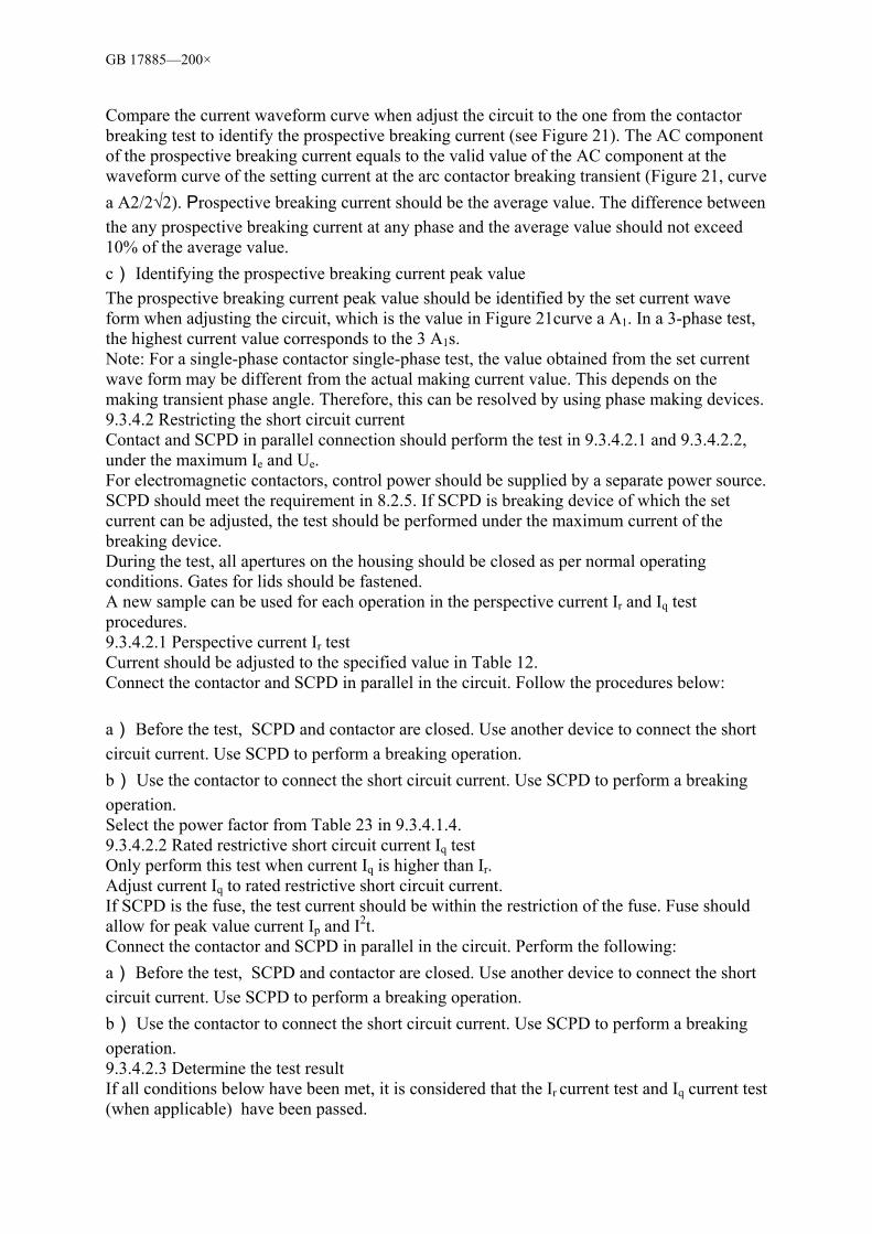
GB 17885—200×
Compare the current waveform curve when adjust the circuit to the one from the contactor breaking test to identify the prospective breaking current (see Figure 21). The AC component of the prospective breaking current equals to the valid value of the AC component at the waveform curve of the setting current at the arc contactor breaking transient (Figure 21, curve a A2/2√2). Prospective breaking current should be the average value. The difference between the any prospective breaking current at any phase and the average value should not exceed 10% of the average value. c) Identifying the prospective breaking current peak value The prospective breaking current peak value should be identified by the set current wave form when adjusting the circuit, which is the value in Figure 21curve a A1. In a 3-phase test, the highest current value corresponds to the 3 A1s. Note: For a single-phase contactor single-phase test, the value obtained from the set current wave form may be different from the actual making current value. This depends on the making transient phase angle. Therefore, this can be resolved by using phase making devices. 9.3.4.2 Restricting the short circuit current Contact and SCPD in parallel connection should perform the test in 9.3.4.2.1 and 9.3.4.2.2, under the maximum Ie and Ue. For electromagnetic contactors, control power should be supplied by a separate power source. SCPD should meet the requirement in 8.2.5. If SCPD is breaking device of which the set current can be adjusted, the test should be performed under the maximum current of the breaking device. During the test, all apertures on the housing should be closed as per normal operating conditions. Gates for lids should be fastened. A new sample can be used for each operation in the perspective current Ir and Iq test procedures. 9.3.4.2.1 Perspective current Ir test Current should be adjusted to the specified value in Table 12. Connect the contactor and SCPD in parallel in the circuit. Follow the procedures below: a) Before the test, SCPD and contactor are closed. Use another device to connect the short circuit current. Use SCPD to perform a breaking operation. b) Use the contactor to connect the short circuit current. Use SCPD to perform a breaking operation. Select the power factor from Table 23 in 9.3.4.1.4. 9.3.4.2.2 Rated restrictive short circuit current Iq test Only perform this test when current Iq is higher than Ir. Adjust current Iq to rated restrictive short circuit current. If SCPD is the fuse, the test current should be within the restriction of the fuse. Fuse should allow for peak value current Ip and I2t. Connect the contactor and SCPD in parallel in the circuit. Perform the following: a) Before the test, SCPD and contactor are closed. Use another device to connect the short circuit current. Use SCPD to perform a breaking operation. b) Use the contactor to connect the short circuit current. Use SCPD to perform a breaking operation. 9.3.4.2.3 Determine the test result If all conditions below have been met, it is considered that the Ir current test and Iq current test (when applicable) have been passed.

GB 17885—200×
a) SCPD successfully breaks the faulty current and the fuse or the fuse component between the housing and the power is not blown. b) The gates or lids on the housing are not parted and can be opened. Housing deformation is allowed as long as housing protection rating is no lower than IP2X. c) Wiring and terminals are intact and not separated.
d) Insulated base should not contain chips which could damage the energised part installations. e) Discharge should not happen on the surface part of the housing. Contactor damage may happen and may be unsuitable for further use. 9.3.5 Overload current withstanding capability Contactors are installed, connected and operated as specified in 9.3.2. Each pole of the contactor is tested at the same time as per overload current requirement and time specified in 8.2.4.3. It is performed in room temperature under convenient voltage. Samples should have no noticeable deformation or damage after test. Note: The resulted I2t value (Joule integral) cannot be used for assessing contactor performance under the short circuit conditions. 9.3.6 Routine test The routine test is performed after each contactor is being manufactured or after the manufacture. The purpose is to verify they meet all the requirements. 9.3.6.1 Overview Routine test conditions should correspond to the specifications in 9.1.2. Actuation range tests in 9.3.3.2 can be performed under common ambience air temperature, but must be calibrated under the normal ambience conditions. 9.3.6.2 Actuation and actuation range The purpose is to verify the actuation characteristics within the range specified in 8.2.1.2. Note: It is not necessary to achieve thermal equilibrium for this test. 9.3.6.3 Dielectric test Test should be performed on dry, intact contactors. Test voltage is as specified in 9.3.3.4.2c). Test time = 1 second. Test voltage is applied: a) Between each pole when main contact is in the closed position (Main contact should be open for parallel connections) b) Between each pole and frame the main contact is in a closed position. When the whole contactor is enclosed in a insulated housing, it should be installed on a metal plate. Test voltage is applied between each pole of the contactor and the metal plate. c) Between the terminals of each pole when the main contact is open. d) Control circuit and auxiliary circuit are as specified in 9.3.3.4.2b) 2). It is not necessary to use the foil in 9.3.3.4.1a). If the tested contactor meets the requirements in 9.3.3.4.2d), the test is considered to have been passed successfully.
GB 17885—200×
Figure 1 Self Tapping
Figure 2 Treading Cutting Screw
Figure 3 Ball Pressure Test Device
BallSample

GB 17885—200×
Measurement Unit: mm
Figure 4: Bending Test Device
Measurement Unit: mm
Clamps
Platform
Dowel Hole
Quality
A-Type B-Type

GB 17885—200×
Figure 5: A-Type, B-Type Modelling Gauge
Measurement Unit: mm
Parts Material: ①Polyamide; ②③④⑤Fe360 Steel
Figure 6: Devices for Pendulum Impact Test
Figure 7: Sample Racks for Mechanical Shock Impacts Measurement Unit: mm
Pivot Plywood
Pivot

GB 17885—200×
Figure 8: Devices for Pendulum Impact Test Measurement Unit: mm
Note: Ball should be in contact with sample when vertical.
Figure 9: Ball Impact Test
Frame
Sample
Installation Rack
Ball Starting Point
Ball Starting Point
Ball Impact Point
Ball Impact Point
Stee
l Rac
k
Steel Supporting Steel Supporting
Sample Sample
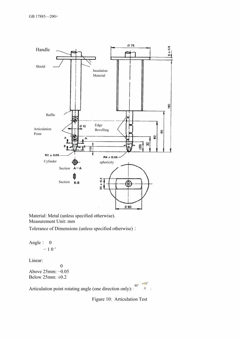
GB 17885—200×
Material: Metal (unless specified otherwise). Measurement Unit: mm Tolerance of Dimensions (unless specified otherwise): Angle: 0 − 1 0 ′ Linear:
0 Above 25mm: −0.05 Below 25mm: ±0.2
Articulation point rotating angle (one direction only):
Figure 10: Articulation Test
Handle
Shield Insulation Material
Baffle
Articulation Point
Edge Bevelling
Cylinder
Section
Section
sphericity
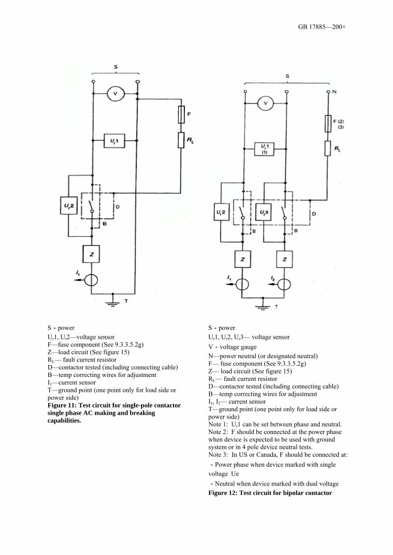
GB 17885—200×
S-power Ur1, Ur2—voltage sensor F—fuse component (See 9.3.3.5.2g) Z—load circuit (See figure 15) RL— fault current resistor D—contactor tested (including connecting cable) B—temp correcting wires for adjustment I1—current sensor T—ground point (one point only for load side or power side) Figure 11: Test circuit for single-pole contactor single phase AC making and breaking capabilities.
S-power Ur1, Ur2, Ur3— voltage sensor V-voltage gauge N—power neutral (or designated neutral) F— fuse component (See 9.3.3.5.2g) Z— load circuit (See figure 15) RL— fault current resistor D—contactor tested (including connecting cable) B—temp correcting wires for adjustment I1, I2— current sensor T—ground point (one point only for load side or power side) Note 1: Ur1 can be set between phase and neutral. Note 2: F should be connected at the power phase when device is expected to be used with ground system or in 4 pole device neutral tests. Note 3: In US or Canada, F should be connected at: -Power phase when device marked with single voltage Ue -Neutral when device marked with dual voltage Figure 12: Test circuit for bipolar contactor
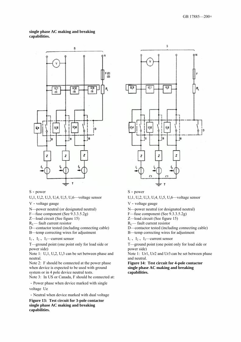
GB 17885—200×
single phase AC making and breaking capabilities.
S-power Ur1, Ur2, Ur3, Ur4, Ur5, Ur6—voltage sensor V-voltage gauge N—power neutral (or designated neutral) F—fuse component (See 9.3.3.5.2g) Z—load circuit (See figure 15) RL— fault current resistor D—contactor tested (including connecting cable) B—temp correcting wires for adjustment I1 、I2 、I3—current sensor T—ground point (one point only for load side or power side) Note 1: Ur1, Ur2, Ur3 can be set between phase and neutral. Note 2: F should be connected at the power phase when device is expected to be used with ground system or in 4 pole device neutral tests. Note 3: In US or Canada, F should be connected at: -Power phase when device marked with single voltage Ue -Neutral when device marked with dual voltage Figure 13: Test circuit for 3-pole contactor single phase AC making and breaking capabilities.
S-power Ur1, Ur2, Ur3, Ur4, Ur5, Ur6—voltage sensor V-voltage gauge N—power neutral (or designated neutral) F—fuse component (See 9.3.3.5.2g) Z—load circuit (See figure 15) RL— fault current resistor D—contactor tested (including connecting cable) B—temp correcting wires for adjustment I1 、I2 、I3—current sensor T—ground point (one point only for load side or power side) Note 1: Ur1, Ur2 and Ur3 can be set between phase and neutral. Figure 14: Test circuit for 4-pole contactor single phase AC making and breaking capabilities.

GB 17885—200×
S—power D—device tested C—selector switch B— diode A—recorder Ra—resistor G—high frequency generator R—load circuit resistor X— load circuit resistor (see 9.3.3.5.2 d) Rp—parallel resistor Cp—shunt capacitor I1,I2,I3—current sensor See figure for high frequency generator position (G) and diode position (B). Connection to ground can only be set at positions shown.
Figure 15: Adjustment for load circuit
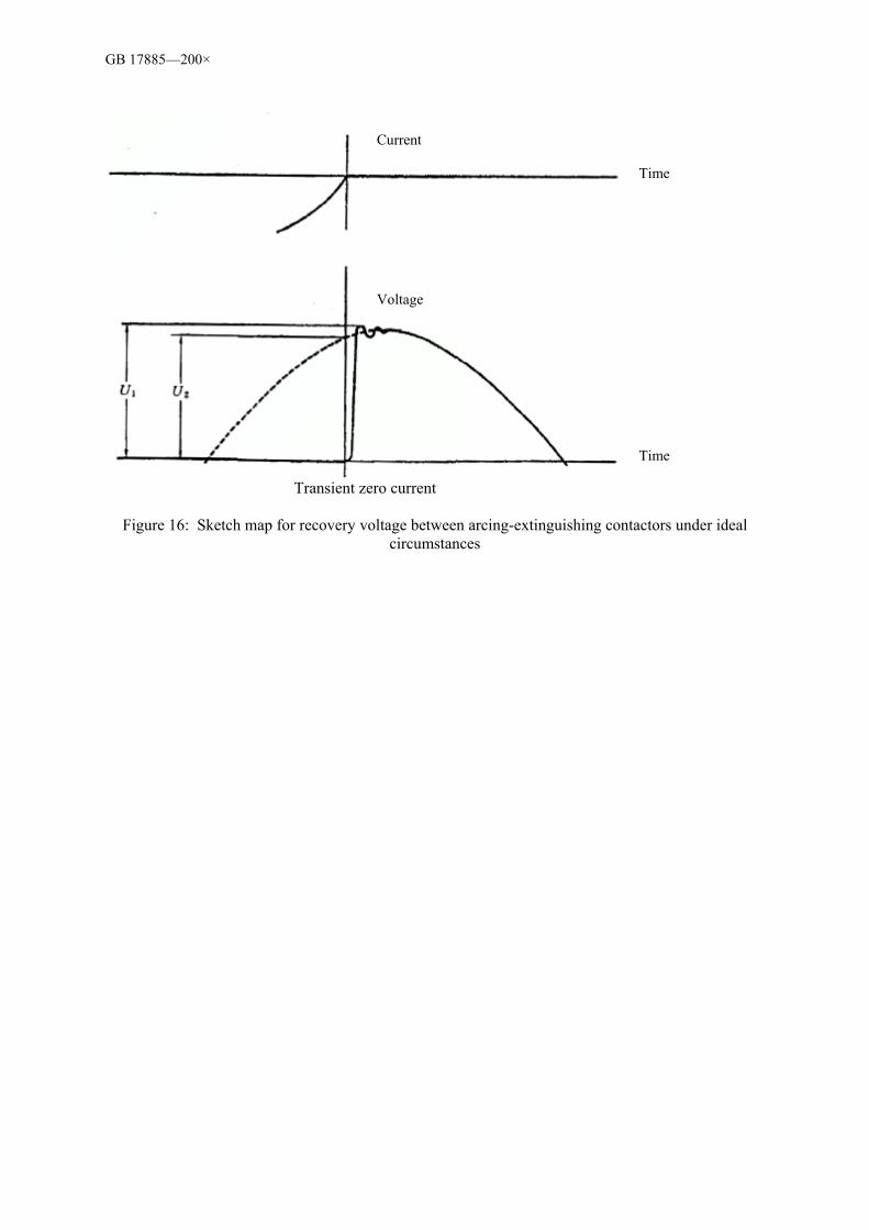
GB 17885—200×
Transient zero current
Figure 16: Sketch map for recovery voltage between arcing-extinguishing contactors under ideal circumstances
Current
Voltage
Time
Time
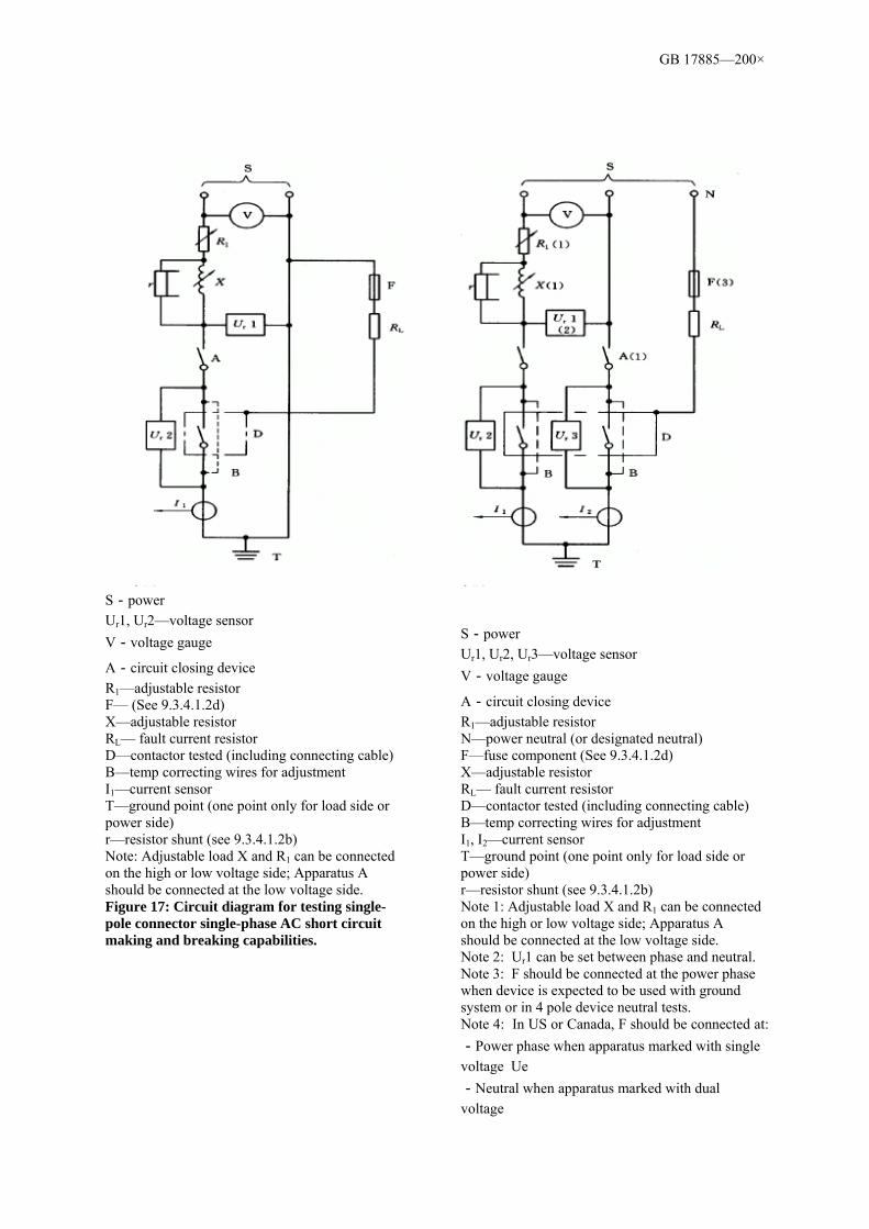
GB 17885—200×
S-power Ur1, Ur2—voltage sensor V-voltage gauge
A-circuit closing device R1—adjustable resistor F— (See 9.3.4.1.2d) X—adjustable resistor RL— fault current resistor D—contactor tested (including connecting cable) B—temp correcting wires for adjustment I1—current sensor T—ground point (one point only for load side or power side) r—resistor shunt (see 9.3.4.1.2b) Note: Adjustable load X and R1 can be connected on the high or low voltage side; Apparatus A should be connected at the low voltage side. Figure 17: Circuit diagram for testing single-pole connector single-phase AC short circuit making and breaking capabilities.
S-power Ur1, Ur2, Ur3—voltage sensor V-voltage gauge
A-circuit closing device R1—adjustable resistor N—power neutral (or designated neutral) F—fuse component (See 9.3.4.1.2d) X—adjustable resistor RL— fault current resistor D—contactor tested (including connecting cable) B—temp correcting wires for adjustment I1, I2—current sensor T—ground point (one point only for load side or power side) r—resistor shunt (see 9.3.4.1.2b) Note 1: Adjustable load X and R1 can be connected on the high or low voltage side; Apparatus A should be connected at the low voltage side. Note 2: Ur1 can be set between phase and neutral. Note 3: F should be connected at the power phase when device is expected to be used with ground system or in 4 pole device neutral tests. Note 4: In US or Canada, F should be connected at: -Power phase when apparatus marked with single voltage Ue -Neutral when apparatus marked with dual voltage

GB 17885—200×
Figure 18: Circuit diagram for testing bipolar connector single-phase AC short circuit making and breaking capabilities.
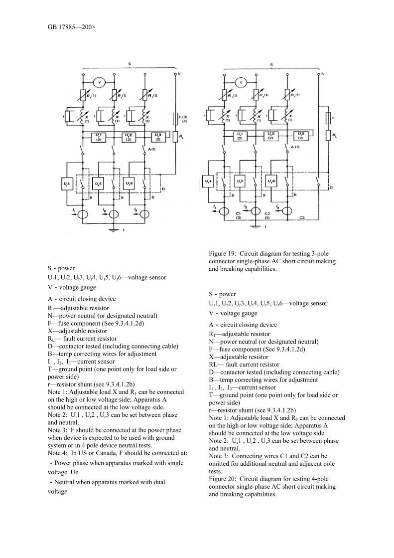
GB 17885—200×
S-power Ur1, Ur2, Ur3, Ur4, Ur5, Ur6—voltage sensor V-voltage gauge
A-circuit closing device R1—adjustable resistor N—power neutral (or designated neutral) F—fuse component (See 9.3.4.1.2d) X—adjustable resistor RL— fault current resistor D—contactor tested (including connecting cable) B—temp correcting wires for adjustment I1 , I2, I3—current sensor T—ground point (one point only for load side or power side) r—resistor shunt (see 9.3.4.1.2b) Note 1: Adjustable load X and R1 can be connected on the high or low voltage side; Apparatus A should be connected at the low voltage side. Note 2: Ur1 , Ur2 , Ur3 can be set between phase and neutral. Note 3: F should be connected at the power phase when device is expected to be used with ground system or in 4 pole device neutral tests. Note 4: In US or Canada, F should be connected at: -Power phase when apparatus marked with single voltage Ue -Neutral when apparatus marked with dual voltage
Figure 19: Circuit diagram for testing 3-pole connector single-phase AC short circuit making and breaking capabilities. S-power Ur1, Ur2, Ur3, Ur4, Ur5, Ur6—voltage sensor V-voltage gauge
A-circuit closing device R1—adjustable resistor N—power neutral (or designated neutral) F—fuse component (See 9.3.4.1.2d) X—adjustable resistor RL— fault current resistor D—contactor tested (including connecting cable) B—temp correcting wires for adjustment I1 , I2, I3—current sensor T—ground point (one point only for load side or power side) r—resistor shunt (see 9.3.4.1.2b) Note 1: Adjustable load X and R1 can be connected on the high or low voltage side; Apparatus A should be connected at the low voltage side. Note 2: Ur1 , Ur2 , Ur3 can be set between phase and neutral. Note 3: Connecting wires C1 and C2 can be omitted for additional neutral and adjacent pole tests. Figure 20: Circuit diagram for testing 4-pole connector single-phase AC short circuit making and breaking capabilities.

GB 17885—200×
a) Test circuit settling wave form
b) Breaking “O” or making “CO” test wave form
Current
Current
Voltage
Voltage
Making
Braking
Prospective making peak current
Prospective symmetric breaking current (effective value)
Applied voltage (effective value)

GB 17885—200×
Note 1: After test current is generated, amplitude of voltage wave form changes with circuit closing device, adjustable impedance, voltage sensor positions, and changes as per test circuit diagrams. Note 2: Presume settling wave and test wave make at the same time. Figure 21:Legend for sing-pole contactor single-phase AC short circuit making and breaking test.
Power voltage (effective value)
Making capability (peak value)
Breaking capability (effective value)
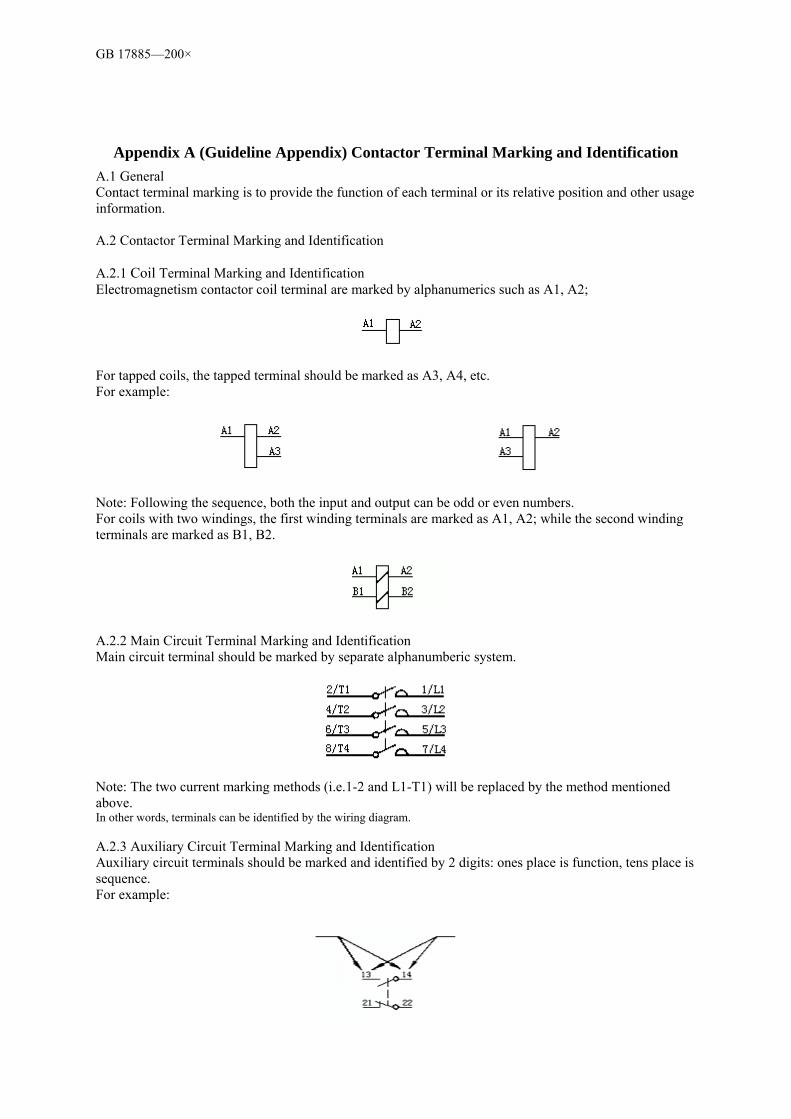
GB 17885—200×
Appendix A (Guideline Appendix) Contactor Terminal Marking and Identification A.1 General Contact terminal marking is to provide the function of each terminal or its relative position and other usage information. A.2 Contactor Terminal Marking and Identification A.2.1 Coil Terminal Marking and Identification Electromagnetism contactor coil terminal are marked by alphanumerics such as A1, A2;
For tapped coils, the tapped terminal should be marked as A3, A4, etc. For example:
Note: Following the sequence, both the input and output can be odd or even numbers. For coils with two windings, the first winding terminals are marked as A1, A2; while the second winding terminals are marked as B1, B2.
A.2.2 Main Circuit Terminal Marking and Identification Main circuit terminal should be marked by separate alphanumberic system.
Note: The two current marking methods (i.e.1-2 and L1-T1) will be replaced by the method mentioned above. In other words, terminals can be identified by the wiring diagram. A.2.3 Auxiliary Circuit Terminal Marking and Identification Auxiliary circuit terminals should be marked and identified by 2 digits: ones place is function, tens place is sequence. For example:

GB 17885—200×
A.2.3.1 Function Number Function number 1 and 2 indicate normally closed circuits, while 3 and 4 indicate normally open circuits.
Note: Dots indicate sequence number, must be with the corresponding numbers. Terminals for converting contact element circuit should be marked with function number 1, 2 and 4.
Function number 5 and 6 (normally closed circuit), 7 and 8 (normally open circuits) indicate special functions. For example:
Time closing breaking contact Time closing making contact Terminals for converting contact element circuit with special functions should be marked with function number 5, 6 and 8. For example:
Time closing breaking and making converting contact
A.2.3.2 Sequence Number Terminals belonging to the same contact element should use the same sequence number marking. All contact elements with the same function numbers should use different sub-sequence numbers. For example:
4 contact elements 3 contact elements
Appendix B (Guideline Appendix) Procedure Test and Sample Quantity
B.1 Procedure Test Test should be carried out as per Table B.1. Each group of procedure tests should be carried out following the sequences specified in the table.

GB 17885—200×
Table B.1 Procedure Test
Procedure Test Procedure Test Case Performance Testing Method
A a. temperature rise test b. operation and operation scope c. rated making and breaking capabilities
8.2.2 8.2.1 8.2.4.1
9.3.3.3 9.3.3.1,9.3.3.2 9.3.3.5
B a. dielectric performancea
b. committed operational performance
8.2.3 8.2.4.2
9.3.3.4 9.3.3.6
C a. water resistance performance
b. overload current stamina c. corrosion resistance performance
8.1.1.2 8.2.4.3 8.1.1.5
9.2.1.2 9.3.5 9.2.1.5
D a. durability of markings
b. impact resistance performance c. measuring of clearance and (when
necessary) creepage distance
8.1.12 8.1.11 8.2.3.2.3, 8.2.3.2.4
9.2.6 9.2.5
E a. mechanical performance of terminals b. performance tests on bolts and nuts for
installations and repairs c. heat resistance performance d. test on abnormal heat resistance and fire
hazards e. CTI testsb
8.1.6 8.1.2 8.1.1.3 8.1.1.4
9.2.4 9.2.2 9.2.1.3 9.2.1.4 9.2.1.6
F a. aging property b. enclosure protection rating
8.1.1.1 8.1.10
9.2.1.1 9.2.3
G Performance under short circuit circumstances 8.2.5
9.3.4
a No need to measure clearance and creepage distance b When no insulation material samples to be tested
B.2 Sample Quantity See Table B.2 for sample quantity.
Table B.2 Sample Quantity Procedure Test Sample Quantity
A B C D E F G
3 3 1 1 1 1 4a
aWhen necessary, a new sample can be used for each task (see 9.3.4.2).
Each sample in a procedure test must pass its test in the procedure. If all samples pass all tests, then the test is approved. If any single test fails, then the procedure test fails. Further tests must be carried out with new test samples until all samples pass their tests.

GB 17885—200×
Appendix C (Guideline Appendix) Instructions for Load Circuit Adjustment Load circuit can be adjusted in a few ways to meet the specifications in 9.3.3.5.3. For example: For circuit diagram, see figure 16. The oscillation frequency f and γ of transient recovery voltage mainly depends on the natural oscillation frequency and the damping of the load circuit. As these values are not relevant to the applied voltage and frequency, AC power can be used to adjust the load circuit, the voltage and frequency of which can be different from those of the device being tested. A diode breaks the circuit when current crosses zero, the oscillation wave form of the recovery voltage will be shown on cathode-ray oscilloscope. The scanning frequency of the oscilloscope should be the same as the power frequency (see figure C.1). To obtain reliable measurement, load circuit is powered by high-frequency signal generator G. The high-frequency signal generator should supply a voltage suitable for diode. The frequency of the selected generator is as below: a)2 kHz when test current ≤ 1 000 A;
b)4 kHz when test current > 1 000 A。 The following are in series circuit with the generator: ——For a)and b), resistor Ra is greater than voltage dropping resistor of the load circuit (Ra≥10 Z, while Z= √R2 +(ωL)2 , and ω=2π×2 000s-1 or ω=2π×4 000s-1) ——switching diode for transient cut-off, normally used for computers, e.g. diffused silicon switching diode with forward current rating less than 1A As generator generates high frequency and load circuit is in fact purely inductive, the applied voltage at the ends of the load circuit is its peak value when current crosses zero. To ensure the load circuit parts are suitable, they must be tested on screen. Make sure the transient voltage curve at the starting point (see A in figure C.1) has virtually horizontal tangent. Actual coefficient γ equals U11/U12. U11 is screen reading. U12 is the reading between y-axis of A and y-axis of the wave form when high-frequency generator stops supplying power to load circuit (see figure C.1). When observing the transient voltage in load circuit and there is no parallel resistor Rp or parallel capacitor Cp, the natural oscillatory frequency can be read on screen. If the natural oscillatory frequency is over the upper-limit of the f value, parallel resistor Rp or parallel capacitor Cp can be connected to obtain suitable frequency value and coefficient γ. Resistor Rp should be non-inductive. Note 1: The higher frequency it generates, the easier it is to be observed and improved. Note 2: Other methods for identifying the frequency and coefficient γ can be adopted (e.g. the use of square-wave current).
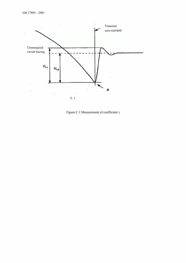
GB 17885—200×
Figure C.1 Measurement of coefficient γ
Transient zero-current
Unenergized circuit tracing

GB 17885—200×
Appendix D (Guideline Appendix) Methods for Identifying Short Circuit Power Factor
Currently there is no precise way of identifying the short circuit power factor or the time constant. For the need of this guideline, one of the following methods can be adopted: Note: Other methods are in consideration. D.1 DC component Phase angle φ is measured via the asymmetrical current DC component curve from the short circuit transient and contact breaking transient. Note: Not applicable when current is measured by current transformer, unless errors introduced by the following can be avoided: Time constant of the transformer and the time constant calculated by its load Magnetic saturation generated by transient magnetic flux and possible magnetic residual Step 1: To identify time constant L/R from DC component formula. DC component formula: Id=Id0e-Rt/L where, Id DC component value at t Id0short circuit transient(t=0)DC component value ttime from transient, s L/Rcircuit time constant, s a. Id、Id0 and t can be obtained from the asymmetrical current DC component curve
b. R/L obtained from DC component formula;
Step 2: To obtain phase-angle φ from φ=arctg(ωL/R) where, ω = 2π f , f is power frequency D.2 Measured by auxiliary generator Use one generator coaxial with the test generator. Compare the phase of the auxiliary generator voltage with the test generator empty load voltage on the oscillogram. Then compare the current phase of the two generators. The difference between the phases is the power factor φ.

GB 17885—200×
Appendix E (Guideline Appendix) Measurement of Clearance and Creepage Distance E.1 Basic Principles In E1~E12, the groove width X is a function of pollution degree, see table below:
Table E.1 Correlation of groove width and pollution degree
Pollution degree Groove Width (min.) mm
1 0.25 2 1.00 3 1.50 4 2.50
If relevant clearance is less than 3mm, groove width can be reduced to 1/3 of the clearance. See Figure E1~E12 for measuring method of clearance and creepage distance. There is no difference between clearances and grooves or any types of insulation. (Clearances are indicated by dotted lines,
while creepage distances are indicated by in the figures.). and: ——Presume arbitrary angle is bridged by the insulation joint with a width of X mm at the least advantageous position ( see Figure E.4); ——When the span over the groove is greater than X mm, measure the creepage distance along the groove contour ( see Figure E.3); ——When the moving part is at the least advantageous position, measure the clearance and the creepage distance. E.2 Use of Rib As the ribs can reduce the effect of pollution and provide good performance on drying, they substantially reduced the current leakage. If the minimum height of the rib is 2mm, the creepage distance can be reduced to 0.8 times of the requirement.
Min. height of the rib
Minimum bottom width of the rib depending on mechanical requirement

GB 17885—200×
Condition: Track of creepage distance includes grooves with a parallel edge or convergent edge (width less than Xmm, any depth). Rule: Creepage distance and clearance as shown in figure are measured as the span over the groove.
Figure E.2
Condition: Track of creepage distance includes grooves with a parallel edge (width greater than or equals to Xmm, any depth). Rule: Clearance is the distance of the dotted line. Creepage distance is the contour of the groove.
Figure E.3
Condition: Track of creepage distance includes a V groove (width greater than Xmm). Rule: Clearance is the distance of the dotted line. Creepage track follows the contour of the groove, but short-circuited by Xmm connection.
Figure E.4
Condition: Track of creepage distance includes a rib.
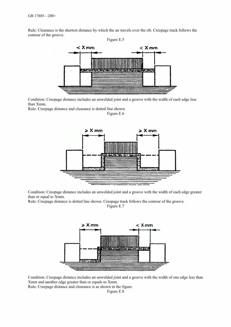
GB 17885—200×
Rule: Clearance is the shortest distance by which the air travels over the rib. Creepage track follows the contour of the groove.
Figure E.5
Condition: Creepage distance includes an unwelded joint and a groove with the width of each edge less than Xmm. Rule: Creepage distance and clearance is dotted line shown.
Figure E.6
Condition: Creepage distance includes an unwelded joint and a groove with the width of each edge greater than or equal to Xmm. Rule: Creepage distance is dotted line shown. Creepage track follows the contour of the groove.
Figure E.7
Condition: Creepage distance includes an unwelded joint and a groove with the width of one edge less than Xmm and another edge greater than or equals to Xmm. Rule: Creepage distance and clearance is as shown in the figure.
Figure E.8

GB 17885—200×
Condition: Creepage distance through an unwelded joint is less than the creepage distance over a separator. Rule: Clearance is the shortest distance by which the air travels over the top of the separator.
Figure E.9
Condition: The clearance between the bolt tip and the concave is wide enough to be taken into consideration. Rule: Creepage distance and clearance is as shown in figure.
Figure E.10
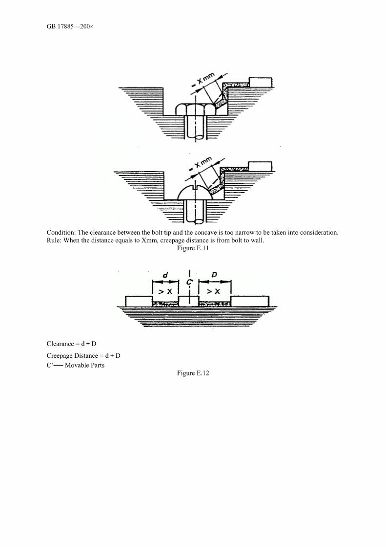
GB 17885—200×
Condition: The clearance between the bolt tip and the concave is too narrow to be taken into consideration. Rule: When the distance equals to Xmm, creepage distance is from bolt to wall.
Figure E.11
Clearance = d+D
Creepage Distance = d+D C’ Movable Parts
Figure E.12
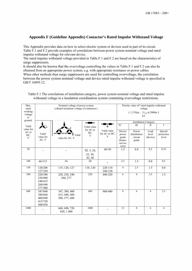
GB 17885—200×
Appendix F (Guideline Appendix) Contactor’s Rated Impulse Withstand Voltage This Appendix provides data on how to select electric system or devices used in part of its circuit. Table F.1 and F.2 provide examples of correlations between power system nominal voltage and rated impulse withstand voltage for relevant device. The rated impulse withstand voltage provided in Table F.1 and F.2 are based on the characteristics of surge suppressors. It should also be known that the overvoltage controlling the values in Table F.1 and F.2 can also be obtained from an appropriate power system, e.g. with appropriate resistance or power cables. When other methods than surge suppressors are used for controlling overvoltage, the correlation between the power system nominal voltage and device rated impulse withstand voltage is specified in GB/T 16895.12.
Table F.1 The correlations of installation category, power system nominal voltage and rated impulse withstand voltage in a insulation coordination system containing overvoltage restrictions.
Nominal voltage of power system
(≤Rated insulation voltage of contactors.) Priority value of" rated impulse withstand
voltage (1.2/50µs, Uimp at 2000m)
kV
Installation Category IV
III II I
Max. rated
working voltage
to ground.
Valid
value for AC or DC, V
Valid
value for AC, V
Valid value for AC, V
Valid value for AC or
DC, V
Valid value
for AC or DC, V
Device power grade
(house-service wire)
Power distribution
circuit grade
Load level
(device)
Special protection
level
50 -
-
12. 5, 24, 25, 30, 42, 48
60-30
1.5
0.8 0.5 0.33
100 66/115 66 60 - 2.5 1.5
0.8 0.5
150 120/208 127/220
115, 120, 127
110, 120
220-110 240-120
4 2.5 1.5
0.8
300 220/380 230/400 240/415 260/440 277/480
220, 230, 240 260, 277
220 440-220
6 4 2.5 1.5
600 347/600 380/660 400/690 415/720 480/830
347, 380, 400 415, 440, 480 500, 577, 600
480 960-480
8 6 4 2.5
1000 - 660, 690, 720 830, 1 000
1000 -
12 8 6 4
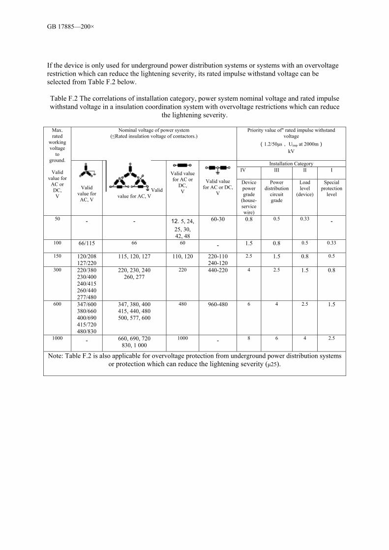
GB 17885—200×
If the device is only used for underground power distribution systems or systems with an overvoltage restriction which can reduce the lightening severity, its rated impulse withstand voltage can be selected from Table F.2 below.
Table F.2 The correlations of installation category, power system nominal voltage and rated impulse withstand voltage in a insulation coordination system with overvoltage restrictions which can reduce
the lightening severity.
Nominal voltage of power system (≤Rated insulation voltage of contactors.)
Priority value of" rated impulse withstand voltage
(1.2/50µs, Uimp at 2000m) kV
Installation Category
IV
III II I
Max. rated
working voltage
to ground.
Valid
value for AC or DC, V
Valid
value for AC, V
Valid value for AC, V
Valid value for AC or
DC, V
Valid value
for AC or DC, V
Device power grade
(house-service wire)
Power distribution
circuit grade
Load level
(device)
Special protection
level
50 -
-
12. 5, 24, 25, 30, 42, 48
60-30
0.8 0.5 0.33 -
100 66/115 66 60 - 1.5
0.8 0.5 0.33
150 120/208 127/220
115, 120, 127
110, 120
220-110 240-120
2.5 1.5
0.8 0.5
300 220/380 230/400 240/415 260/440 277/480
220, 230, 240 260, 277
220 440-220
4 2.5 1.5
0.8
600 347/600 380/660 400/690 415/720 480/830
347, 380, 400 415, 440, 480 500, 577, 600
480 960-480
6 4 2.5 1.5
1000 - 660, 690, 720 830, 1 000
1000 -
8 6 4 2.5
Note: Table F.2 is also applicable for overvoltage protection from underground power distribution systems or protection which can reduce the lightening severity (µ25).
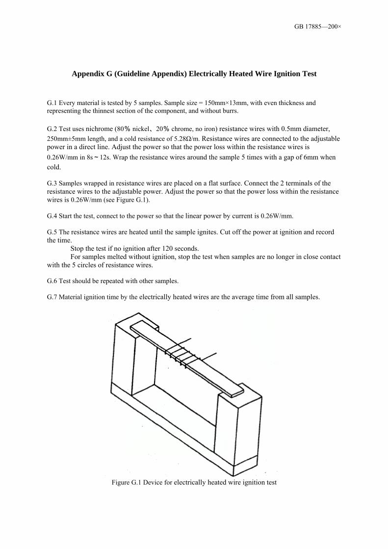
GB 17885—200×
Appendix G (Guideline Appendix) Electrically Heated Wire Ignition Test
G.1 Every material is tested by 5 samples. Sample size = 150mm×13mm, with even thickness and representing the thinnest section of the component, and without burrs. G.2 Test uses nichrome (80% nickel、20% chrome, no iron) resistance wires with 0.5mm diameter, 250mm±5mm length, and a cold resistance of 5.28Ω/m. Resistance wires are connected to the adjustable power in a direct line. Adjust the power so that the power loss within the resistance wires is 0.26W/mm in 8s~12s. Wrap the resistance wires around the sample 5 times with a gap of 6mm when cold. G.3 Samples wrapped in resistance wires are placed on a flat surface. Connect the 2 terminals of the resistance wires to the adjustable power. Adjust the power so that the power loss within the resistance wires is 0.26W/mm (see Figure G.1). G.4 Start the test, connect to the power so that the linear power by current is 0.26W/mm. G.5 The resistance wires are heated until the sample ignites. Cut off the power at ignition and record the time. Stop the test if no ignition after 120 seconds. For samples melted without ignition, stop the test when samples are no longer in close contact with the 5 circles of resistance wires. G.6 Test should be repeated with other samples. G.7 Material ignition time by the electrically heated wires are the average time from all samples.
Figure G.1 Device for electrically heated wire ignition test