National Pollutant Discharge Elimination System /State ... · Summary Statement ... Your petition...
88
1 Permittee Facility Name Permit Number: MN0071013 Poly Met Mining, Inc. NorthMet Project P.O. Box 475 6500 County Road 666 Hoyt Lakes, MN 55750 Hoyt Lakes, MN 55750 Current Permit Expiration: Not Applicable Public Comment Period Begins: January 31, 2018 Period Ends: March 16, 2018 Receiving Waters: • Wetlands in the headwater area of Unnamed Creek Class 2D, 3D, 4C, 5, 6) • Wetlands in the headwater area of Trimble Creek (Class 2D, 3D, 4C, 5, 6) • Second Creek (Class 2B, 3C, 4A, 4B, 5, 6) Proposed Action: Permit Issuance Permitting Contact PolyMet Water Quality Permit Comment - 4 th Floor Minnesota Pollution Control Agency 520 Lafayette Road North St. Paul, MN 55155-4194 Phone: (651) 757-2455; (833) 722-9016 National Pollutant Discharge Elimination System /State Disposal System (NPDES/SDS) Permit Program Fact Sheet wq-wwprm1-51k
Transcript of National Pollutant Discharge Elimination System /State ... · Summary Statement ... Your petition...

1
Permittee Facility Name Permit Number: MN0071013 Poly Met Mining, Inc. NorthMet Project P.O. Box 475 6500 County Road 666 Hoyt Lakes, MN 55750 Hoyt Lakes, MN 55750
Current Permit Expiration: Not Applicable
Public Comment Period Begins: January 31, 2018 Period Ends: March 16, 2018
Receiving Waters: · Wetlands in the headwater area of Unnamed Creek Class 2D, 3D, 4C, 5, 6)· Wetlands in the headwater area of Trimble Creek (Class 2D, 3D, 4C, 5, 6)· Second Creek (Class 2B, 3C, 4A, 4B, 5, 6)
Proposed Action: Permit Issuance
Permitting Contact
PolyMet Water Quality Permit Comment - 4th Floor Minnesota Pollution Control Agency
520 Lafayette Road North St. Paul, MN 55155-4194
Phone: (651) 757-2455; (833) 722-9016
National Pollutant Discharge Elimination System /State Disposal System (NPDES/SDS) Permit Program Fact Sheet
wq-wwprm1-51k

2
Table of Contents
Purpose and Participation...................................................................................................... 4 Applicable Statutes .................................................................................................... 4 Purpose ...................................................................................................................... 4 Public Participation .................................................................................................... 4
Facility Overview……………………………………………………………………………………………………………… 6
Maps of the Permitted Facility…………………………………………………………………………………………. 7
Facility Description ................................................................................................................. 14 Mine Site .................................................................................................................... 14 Plant Site .................................................................................................................... 16 Wastewater Treatment System (WWTS) ................................................................... 19 Transportation and Utility Corridors ......................................................................... 22
Summary Statement .............................................................................................................. 23
Flow Schematic ..................................................................................................................... 24
Process Flow Diagram ........................................................................................................... 25
Proposed Outfall Locations ................................................................................................... 26
Receiving Waters and Downstream Waters .......................................................................... 28
Reasonable Potential ............................................................................................................ 31
Proposed Permit Limits ......................................................................................................... 39
Internal Performance Monitoring ......................................................................................... 43
Proposed Monitoring ............................................................................................................ 46 Monitoring Group Summary ..................................................................................... 46 Wastewater Treatment System Monitoring ............................................................. 48 Mine Site Monitoring ................................................................................................ 50 Plant Site Monitoring ................................................................................................. 54 Additional Monitoring ................................................................................................ 58 Nutrients ................................................................................................................... 58
Special Permit Requirements ................................................................................................. 60

3
Allowable Discharge ................................................................................................... 60 No Unauthorized Discharge to Surface Waters ......................................................... 62 Management of Water During Construction of FTB Seepage Containment System. 69 Attenuation of Legacy Pollutants ............................................................................... 72 Stormwater ................................................................................................................ 75 Model Verification ..................................................................................................... 78 Annual Groundwater Evaluation Report and Annual Comprehensive Performance
Monitoring Evaluation Report ....................................................................... 80 Hydrometallurgical Residue Facility Construction………………………………………………… 82 Total Facility Requirements ................................................................................................... 85 Summary of Plan, Report & Work Plan Submittals ............................................................... 85 Mercury Minimization Plan (MMP) ...................................................................................... 85 Cross Media Analysis ............................................................................................................. 86 Antidegradation in Surface Waters ....................................................................................... 86 Nondegradation of Groundwater .......................................................................................... 86 Permit Expiration ................................................................................................................... 87 Attachments ........................................................................................................................ 87 Attachment 1 – Summary of Monitoring Stations and Monitoring Requirements Attachment 2 - Chemical Additives Attachment 3 - Antidegradation in Surface Waters Attachment 4 - Nondegradation in Groundwater Attachment 5 – Acronyms and Abbreviations

4
Purpose and Participation Applicable Statutes This fact sheet has been prepared according to the Title 40 Federal Code of Regulations (CFR) 124.8 and 124.56 and Minn. R. 7001.0100, Subp. 3 for a draft NPDES/SDS permit to construct and/or operate wastewater treatment facilities and to discharge into waters of the State of Minnesota. Purpose This fact sheet outlines the principal issues related to the preparation of this draft permit and documents the decisions that were made in the determination of the effluent limitations and conditions of this permit. Public Participation You may submit written comments on the terms of the draft permit or on the Commissioner’s preliminary determination. Your written comments must include the following: 1. A statement of your interest in the permit application or the draft permit. 2. A statement of the action you wish the Minnesota Pollution Control Agency (MPCA) to take,
including specific references to sections of the draft permit that you believe should be changed. 3. The reasons supporting your position, stated with sufficient specificity as to allow the
Commissioner to investigate the merits of your position. Public informational meetings on the draft NPDES/SDS permit are being held on February 7, 2018, in Aurora, MN and February 8, 2018, in Duluth, MN. A public informational meeting is an informal meeting which the MPCA may hold to help clarify and resolve issues. For more information on the public informational meetings, visit https://www.pca.state.mn.us/public-notices. In addition, you may submit a petition for a contested case hearing. A contested case hearing is a formal hearing before an administrative law judge. Your petition requesting a contested case hearing must include a statement of reasons or proposed findings supporting the MPCA decision to hold a contested case hearing pursuant to the criteria identified in Minn. R. 7000.1900, subp. 1, a statement of the issues proposed to be addressed by a contested case hearing, and the specific relief requested. To the extent known, your petition should include a proposed list of witnesses to be presented at the hearing, a proposed list of publications, references or studies to be introduced at the hearing, and an estimate of time required for you to present the matter at the hearing. You must submit all comments, requests, and petitions during the public comment period identified on page 1 of this notice. All written comments, requests, and petitions received during the public comment period will be considered in the final decisions regarding the permit. If the MPCA does not receive any written comments, requests, or petitions during the public comment period, the Commissioner or other MPCA staff as authorized by the Commissioner will make the final decision concerning the draft permit.

5
Comments, petitions, and/or requests must be submitted by the last day of the public comment period to:
PolyMet Water Quality Permit Comment – 4th Floor Minnesota Pollution Control Agency
520 Lafayette Road North St. Paul, MN 55155-4194
The permit will be issued if the MPCA determines that the proposed Permittee or Permittees will, with respect to the facility or activity to be permitted, comply or undertake a schedule to achieve compliance with all applicable state and federal pollution control statutes and rules administered by the MPCA and the conditions of the permit and that all applicable requirements of Minn. Stat. ch. 116D and the rules promulgated thereunder have been fulfilled. More detail on all requirements placed on the facility may be found in the Permit document.

6
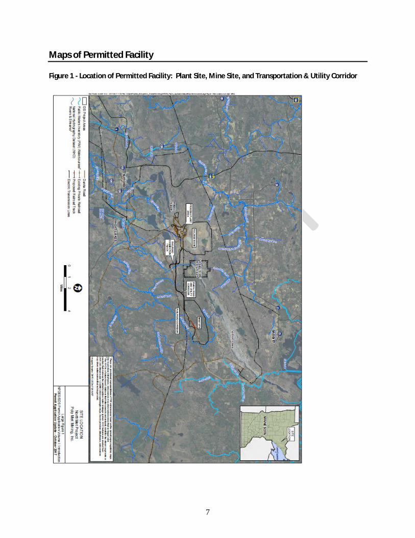
Facility Overview Poly Met Mining, Inc. (PolyMet) proposes to develop a copper-nickel-platinum-group elements (PGE) mine and associated processing facilities. The proposed mine and processing facilities, known as the NorthMet Project (Project), are described in detail in the NPDES/SDS Permit Application dated July 2016 and updated in October 2017. The Project is located south of the city of Babbitt and north of the city of Hoyt Lakes in St. Louis County, Minnesota, as shown on Figure 1. The Project consists of the Mine Site, the Plant Site, and the Transportation and Utility Corridors that connect them. The Mine Site is a relatively undisturbed site that will be developed into an open pit mine and is located approximately six miles south of the city of Babbitt and two miles south of the Northshore Mining Company’s active, open pit taconite mine (known as Northshore Mining’s Peter Mitchell Mine). The Plant Site is located at the former LTV Steel Mining Company (LTVSMC) / Cliffs Erie, LLC (Cliffs Erie) taconite processing facility located approximately six miles north of the city of Hoyt Lakes and will include refurbished and new ore processing and waste disposal facilities. The Plant Site includes the Colby Lake Corridor, which contains an existing pipeline that will be refurbished as necessary and will supply water from Colby Lake to the Plant Site. The Mine Site and the Plant Site are connected by approximately 7- to 8-mile-long Transportation and Utility Corridors, which will include new and upgraded infrastructure to link activities at the Mine Site and Plant Site. Figures 2, 4 and 6 show the Project’s currently planned configurations at full build-out in approximately Mine Year 11. Figures 3, 5 and 7 show the Project’s footprint overlain on USGS topographic maps. The Project is located in:
· Sections 1, 2, 3, 4, 9, 10, 11, 12, 15, 16, 17, and 18 of T59N, R13W; · Sections 2, 3, 4, 5, 8, 9, 10, 11, 13, 14, 15, 16, 17, 23, and 24 of T59N, R14W; and · Sections 32, 33, and 34 of T60N, R14W.
7
Maps of Permitted Facility Figure 1 - Location of Permitted Facility: Plant Site, Mine Site, and Transportation & Utility Corridor

8
Figure 2 - Project Layout of Permitted Facility: Full Buildout at Approximately Mine Year 11

9
Figure 3 - Mine Site Location Map

10
Figure 4 - Mine Site Layout: Full Buildout at Approximately Mine Year 11

11
Figure 5 - Plant Site Map

12
Figure 6 - Plant Site Layout: Tailings Basin & Hydrometallurgical Residue Facility at Approximately Mine Year 20

13
Figure 7 - Transportation and Utility Corridors Map
14
Facility Description Mine Site The Mine Site is a relatively undisturbed site that will be developed into an open pit mine. Development of the Mine Site for the Project will include construction of new facilities, including mine pits, ore handling facilities, waste rock stockpiles, an overburden storage area, mine water management systems, an Equalization Basin Area, and supporting infrastructure. The Mine Site will include the following Project features:
· three mine pits (the East Pit, West Pit, and Central Pit) · ore handling facilities, including an Ore Surge Pile (OSP) and a Rail Transfer Hopper (RTH) · Category 1, 2/3, and 4 Waste Rock Stockpiles and the OSP with engineered systems such as
liners, covers, and a groundwater containment system, to manage precipitation that will run off of or percolate through the stored waste rock
· an Overburden Storage and Laydown Area (OSLA) to provide space to sort and store unsaturated mineral overburden and peat used for construction and reclamation
· mine water collection systems and an Equalization Basin Area to collect mine water from the mine pits, the stockpiles, the ore handling facilities, OSLA, construction areas, and the driving surface of haul roads
· a Central Pumping Station (CPS), Construction Mine Water Pumping Station, and Mine to Plant Pipelines (MPP) to transport mine water from the Mine Site to the Plant Site
· stormwater management systems The location of the Mine Site and Mine Site features is shown on Figures 3 and 4. Mine Pits and Mine Pit Dewatering Mine Pits The Project will involve mining from three open pits, the East Pit, the West Pit and the Central Pit. Mining will begin in the East Pit in Mine Year 1 followed by commencement of mining in the West Pit. Mining from the West Pit is anticipated throughout the life of the mine. Mining from the East Pit will cease before the end of the life of the mine, and thereafter backfilling of the pit with waste rock from the temporary Category 2/3 and Category 4 waste rock stockpiles will begin. Mining from the Central Pit will begin once the Category 4 waste rock stockpile is backfilled into the East Pit. Once backfilling begins, waste rock from the West and Central Pits will be used to backfill the East Pit, as well as the Central Pit, once mining ceases in each pit. The maximum surface footprint of the East Pit, the West Pit and Central Pits will be approximately 155 acres, 321 acres and 52 acres respectively, and maximum depths will be approximately 700 feet, 630 feet and 350 feet respectively. Mine Pit Dewatering Each of the mine pits will require mine pit dewatering to remove groundwater and runoff from areas within the pits. This water will be directed to sumps within the pits where it will be collected and pumped to the equalization basins for further conveyance to the Waste Water Treatment System (WWTS) at the Plant Site.
15
Waste Rock Stockpiles Temporary Category 2/3 Waste Rock and Category 4 Waste Rock Stockpiles and Ore Surge Pile The Category 2/3 Waste Rock Stockpile and the Category 4 Waste Rock Stockpile will temporarily store higher sulfur waste rock that may generate acidic leachate until the waste rock can be backfilled into the East and Central Mine Pits. The Ore Surge Pile will be used to temporarily store ore, with ore moving in and out as needed to meet mine and plant conditions. Each of these temporary features will include an engineered liner system consisting of a compacted foundation, an underdrain system (if needed), an geomembrane liner over a compacted soil liner and an overliner drainage layer. Drainage from each stockpile will be collected in a sump and pond system and will be conveyed to the equalization basins for further conveyance to the WWTS at the Plant Site for further treatment. The maximum surface footprint of the Category 2/3 Waste Rock Stockpile and the Category 4 Waste Rock Stockpile is expected to be approximately 180 acres and 57 acres respectively, with maximum heights above ground surface of approximately 200 feet and 180 feet respectively. Permanent Category 1 Waste Rock Stockpile The Category 1 Waste Rock Stockpile will be the only permanent waste rock stockpile on site. Category 1 waste rock is of lower sulfur content and is not expected to generate acidic leachate but may leach heavy metals. Drainage from the Category 1 Waste Rock Stockpile will be collected by a groundwater containment system that consists of a low permeability barrier with a collection system on the inward side that will be operated to maintain an inward hydraulic gradient. The drainage collected by the groundwater containment system will be conveyed to the equalization basins for further conveyance to the WWTS at the Plant Site for treatment. The maximum surface footprint of the Category 1 Waste Rock stockpile at full development is expected to be approximately 526 acres with a maximum height of approximately 280 feet above the ground surface. Overburden Storage and Laydown Area (OSLA) The OSLA is a temporary storage area for unsaturated overburden and peat that will be used in construction and reclamation. The OSLA will be graded and compacted to direct runoff to a collection pond from where it will be pumped to the Construction Mine Water Basin for further conveyance to the FTB at the Plant Site via the Mine to Plant Pipelines (MPP) or, during East and Central Pit filling, for conveyance to these pits. Mine Water Collection Systems Mine water will include water that has contacted surfaces disturbed by mining activities including the aforementioned mine pit dewatering and stockpile drainage as well as runoff contacting ore, waste rock and Mine Site haul road surfaces. Mine water will be intercepted throughout the Mine Site by ditches, dikes, stockpile liners, and the stockpile groundwater containment system and routed to the Equalization Basin Area where it will be kept segregated in ponds by waste strength as described in the Plant Site section below. There will be no discharge of mine water or other process wastewater to surface waters from the Mine Site. Internal monitoring points, groundwater monitoring wells and piezometers, and surface water monitoring will be located at or near the Mine Site and are described in the Monitoring Summary section of the permit.

16
Plant Site The Plant Site is located approximately 6-7 miles west of the Mine Site. It is a developed site which includes a former taconite processing facility and tailings basin previously operated by LTVSMC. Redevelopment of the Plant Site for the Project will include refurbishment of former LTVSMC processing facilities and construction of new facilities. Plant Site features will include:
· a Beneficiation Plant · a Hydrometallurgical Plant · a Flotation Tailings Basin (FTB) including Seepage Capture Systems · a Hydrometallurgical Residue Facility (HRF) · a Waste Water Treatment System (WWTS) · a Sewage Treatment System · other ancillary facilities (e.g., Colby Lake water pipeline).
The location of the Plant Site and Plant Site features is shown on Figures 5 and 6. Beneficiation Plant and Flotation Tailings Basin Beneficiation Plant The Beneficiation Plant will process ore to produce nickel and copper concentrates. Ore will be crushed at the Coarse Crusher Building, ground in the semi-autogenous grinding mill and ball mill at the Concentrator Building, and then sent to the Flotation Building. In flotation, the minerals containing base and precious metals will be separated from the tailings using a combination of flotation reagents. The Beneficiation Plant will process approximately 32,000 tons of ore per day, and produce approximately 660 tons per day of copper and nickel concentrates and approximately 31,340 tons per day of Flotation Tailings. Copper concentrates will be dewatered and shipped to customers via rail. Nickel concentrates will be dewatered and shipped directly to customers via rail until the Hydrometallurgical Plant is built to process them on-site. Flotation Tailings will be slurried to the FTB. The Beneficiation Plant will produce Flotation Tailings throughout the planned 20 years of ore processing. Flotation Tailings will be pumped as a slurry to the FTB, which will be constructed atop Cells 1E and 2E of the former LTVSMC tailings basin. Water from the FTB will be recycled back to the Beneficiation Plant and will not be directly discharged during operations. The Beneficiation Plant will require an annual average of approximately 13,800 gpm of water for processing. Nearly all this water (99%) will be piped with the tailings to the FTB; less than 1% will be lost to evaporation in the plant or included with the concentrate. Water for Beneficiation Plant processes will come primarily from the FTB Pond. Other minor sources of water will include water in the raw ore, reagents, and gland seals of slurry pumps. Make-up water, as needed, will be drawn from the Plant Reservoir which will be supplied with raw water pumped from Colby Lake under terms of a water appropriation permit from the Minnesota Department of Natural Resources (MDNR). Average annual make-up water demand from Colby Lake is expected to vary from about 260 gpm to up to 1,760 gpm (with an average of about 760 gpm) depending on precipitation and Mine Year. Water will be conveyed from Colby Lake via an existing pipeline, located within the Colby Lake Corridor, previously used by LTVSMC in its taconite operations. PolyMet will refurbish the existing pipeline and pumphouse as necessary for its use.

17
Flotation Tailings Basin The FTB is designed to contain flotation tailings generated over the planned 20 years of operation. The FTB will be constructed atop the existing LTVSMC tailings basin. The FTB will be constructed in stages, gradually increasing in elevation and size. Initially, flotation tailings will be placed in existing Cell 2E. Eventually (currently estimated to be approximately Mine Year 7), Cell 2E will merge with Cell 1E and flotation tailings will be placed in combined Cell1E/2E. The FTB perimeter dams will be raised in an upstream construction method utilizing LTVSMC coarse tailings. A bentonite amended layer will be placed on exterior sides of the FTB dams to limit oxidation of the tailings. The FTB dams will be constructed and operated in accordance with Minnesota dam safety regulations administered by the MDNR. The FTB Pond will receive water from the following sources during operations: process water/tailings slurry from the Beneficiation Plant, captured seepage from the FTB seepage capture systems, treated mine water, filter backwash and clean-in-place wastes from the WWTS, construction mine water/OSLA runoff from the Mine Site, treated effluent from the Sewage Treatment System, and precipitation and runoff from within the FTB dams and tributary to the FTB Pond. The FTB is designed and will be operated to prevent overflow of the system – there will be no direct discharge from the FTB Pond to any receiving waters. Pond water levels will be managed to maintain adequate freeboard by adjusting the relative amount of collected tailings basin seepage routed to the FTB Pond and to the WWTS. Freeboard requirements and other terms relating to the operation of the FTB are established by the MDNR dam safety permit. FTB Seepage Capture Systems Historically, water has seeped from the LTVSMC tailings basin by infiltrating through the tailings basin and migrating through the base of the external dam faces. This seepage contributed to exceedances of permit effluent limitations established in the NPDES/SDS permit currently held by Cliffs Erie for the former LTVSMC tailings basin. Cliffs Erie and MPCA entered into a Consent Decree in 2010 to resolve the permit limit exceedances associated with the tailings basin. Cliffs Erie has taken various measures to address these exceedances and is in compliance with the Consent Decree; however, the Consent Decree does not require elimination of the seepage and seepage from the tailings basin is continuing. As part of the Project, PolyMet will construct seepage capture systems to collect seepage from the FTB. The FTB Seepage Containment System and the FTB South Seepage Management System (collectively known as the FTB seepage capture systems) will collect water seeping from the combined former LTVSMC basin and the FTB (collectively, the Tailings Basin) via surface or shallow groundwater flow. The FTB seepage capture systems are expected to provide a permanent remedy to the water quality exceedances associated with the seepage from the existing tailings basin. The FTB Seepage Containment System will surround the western and northern sides and extend to a portion of the eastern side of the Tailings Basin. It will consist of a cutoff wall installed to the top of the bedrock, with a collection trench and drain pipe installed on the upgradient side (Tailings Basin side) of the cutoff wall. The FTB Seepage Containment System will collect water seeping from the Tailings Basin via surface and shallow groundwater flow, as well as runoff from the exteriors of the dams on the northern, northwestern, western, and eastern sides of the Tailings Basin, and from the small watershed area between the toes of the dams and the FTB Seepage Containment System.

18
The FTB South Seepage Management System, which currently operates as the temporary Cliffs Erie SD026 pumpback system installed under the 2010 Consent Decree, consists of a berm, trench, and pumpback system and collects seepage on the southern side of the FTB. During Project operations, PolyMet will upgrade the existing system to enhance the degree of seepage collection as necessary. Seepage from both the FTB Seepage Containment System and the FTB South Seepage Management System will be routed to the WWTS for treatment prior to discharge to the receiving waters. This discharge of treated water will augment water levels in the receiving waters, which will receive less in-flow due to the installation of the FTB seepage capture systems. As discussed further below, this augmentation is intended to maintain the hydrologic and ecologic integrity of the receiving waters. This augmentation will be subject not only to this NPDES/SDS permit for the Project, but also a MDNR water appropriation permit. Some seepage will be also be recycled directly to the FTB Pond for reuse in the processing facilities. The amount of seepage to be treated at the WWTS and discharged will depend on operational factors, precipitation, allowable discharge requirements of 40 CFR part 440, and requirements of the MDNR water appropriation permit. Hydrometallurgical Plant/Hydrometallurgical Residue Facility Hydrometallurgical Plant The Hydrometallurgical Plant will process nickel concentrates from the Beneficiation Plant, extracting a copper concentrate, a mixed nickel-cobalt (Ni/Co) hydroxide, and a gold and platinum-group elements (Au/PGE) precipitate. The Hydrometallurgical Plant may not be built for several years after mining starts. Before the Hydrometallurgical Plant is built, the company will ship the nickel concentrates from the Beneficiation Plant directly to customers. The timing for construction of the Hydrometallurgical Plant will depend on customer requirements and overall Project economics. The hydrometallurgical process will involve high pressure and temperature autoclave leaching followed by several solution purification steps. Inputs will include the nickel concentrates from the Beneficiation Plant, water from the HRF Pond and the Plant Reservoir, various process consumables, and chemical additives. Waste residues from the hydrometallurgical process will be pumped as a slurry for final disposal to the HRF. The Hydrometallurgical Plant and HRF will operate as a closed-loop system with no discharge to the environment or to the FTB/WWTS system. Water for Hydrometallurgical Plant processes will include recycled HRF water from the HRF Pond (approximately 172 gpm) and make-up water from Colby Lake via the Plant Reservoir (at approximately 230 gpm). If all nickel concentrate streams from the Beneficiation Plant are processed at the Hydrometallurgical Plant, annual production currently is expected to total about 113,000 tons of copper concentrate, 18,000 tons of mixed nickel-cobalt (Ni/Co) hydroxide, and 500 tons of gold and platinum-group elements (Au/PGE) precipitate. This will result in generation of approximately 313,000 tons of residue per year for disposal in the HRF. These totals will decrease if some flotation concentrates are shipped directly to customers. Hydrometallurgical Residue Facility (HRF) The HRF will be designed to permanently store residue from the hydrometallurgical process generated over the life of the Project and may also receive wastewater treatment solids from the WWTS. The HRF will be constructed at the former LTVSMC Emergency Basin (Emergency Basin) near the southwestern corner of the existing tailings basin.

19
The HRF will function as a large-scale sedimentation basin. Residue will be pumped as slurry to the HRF, where it will settle out. Residue slurry from the Hydrometallurgical Plant will be pumped to the HRF through a pipe with multiple discharge points into the HRF. A pond will be maintained within the cell such that the solid fraction of the slurry (the Residue) settles out, while the majority of the liquid fraction is recovered by the return water system and pumped back to the Hydrometallurgical Plant for reuse. The water level and dam height in the HRF will be managed as needed to facilitate Residue deposition at the desired locations within the HRF and to achieve the desired water clarity for process water at the Hydrometallurgical Plant in accordance with Minnesota dam safety regulations administered by the MDNR. The HRF is designed as a closed system: no water from the HRF will be released to the environment through overflow or outlet structures. The HRF is designed with a double liner with a Leakage Collection System between the two liners to prevent leakage to groundwater. Any leakage collected in the leakage collection system will be routed back to the HRF pond. The HRF Leakage Collection System is further described in Volume 6 of the October 2017 Permit Application. Plant Site Sewage Treatment System Sewage generated from various buildings at the Plant Site, sewage generated at the Mine Site, and filter backwash from the Plant Site Potable Water Treatment Plant will be collected and routed to a Plant Site Sewage Treatment System (STS). The STS will consist of a stabilization pond system. The STS will be designed for an initial average daily flow of approximately 8,500 gallons per day (gpd) and average wet weather flow of approximately 21,500 gpd with expansion up to an average daily flow of approximately 13,750gallons per day (gpd) and average wet weather flow of approximately 26,750 gpd. Existing piping will be used to collect sewage from existing facilities at the Plant Site and will be refurbished to minimize infiltration and inflow to the collection system. New piping and associated infrastructure will also be added to connect new Plant Site facilities to the collection system and the stabilization ponds. Sewage at the Mine Site will be collected in portable facilities and trucked to the Plant Site STS. The proposed stabilization ponds will consist of two lined primary ponds and one lined secondary pond with operating depths of approximately four feet. The secondary pond will discharge to the FTB Pond via a pump station. The controlled discharge will occur in the spring and fall of each year. Each controlled discharge will typically last 10 to 14 days, depending on weather conditions. Wastewater Treatment System (WWTS) The WWTS will be located at the Plant Site and will house the process equipment for two separate treatment trains known as the mine water treatment trains and the tailings basin seepage treatment train. The primary components of the WWTS for the Project will include the Equalization Basin Area located at the Mine Site, the Mine to Plant Pipelines (MPP), and the WWTS building and associated Pretreatment Basin. The WWTS will treat mine water and tailings basin seepage. Mine water flows will be segregated based on projected water quality or waste strength and treated in two mine water treatment trains. The mine water chemical precipitation train will treat high-concentration mine water and also treat WWTS membrane treatment concentrate. The mine water filtration train will treat low-concentration mine

20
water using membrane separation. Separately, the WWTS will also treat tailings basin seepage using a combination of membrane separation treatment technologies (such as reverse osmosis and/or nanofiltration). Equalization Basin Area In the Equalization Basin Area located at the Mine Site, mine water will be managed based on the projected water quality. Construction mine water and OSLA runoff will be routed to the Construction Mine Water Basin. Mine water from low-volume sources (e.g., temporary waste rock stockpiles) that are expected to have relatively high concentrations of dissolved constituents will be routed to the High Concentration Equalization (HCEQ) Basin. Mine water from high-volume sources, (e.g., mine pits, haul roads and RTH area) that are expected to have relatively low concentrations of dissolved constituents will be routed to the Low Concentration Equalization (LCEQ) Basin 1 and LCEQ Basin 2. The distinction between these two groups of mine water sources is the basis for the use of two separate treatment trains: chemical precipitation for the low-volume, high-concentration flows and membrane separation for the high-volume, low-concentration flows. The sources that are routed to each of these basins is part of the adaptive management approach of the WWTS design. Mine to Plant Pipelines Three pipelines (collectively referred to as the MPP) will convey water between the Mine Site and the Plant Site. The Construction Mine Water Pipeline will transport construction mine water and runoff from the OSLA Pond to the FTB. Once pit backfilling begins, runoff from the OSLA pond will be routed to the East and Central Pits, and concurrently water from the WWTS will be conveyed through the Construction Mine Water Pipeline to the East and Central Pits to aid in pit flooding. The Low Concentration Mine Water Pipeline will transport mine water from the LCEQ Basins to the mine water filtration treatment train at the WWTS; and the High Concentration Mine Water Pipeline will transport mine water from the HCEQ Basin to the mine water chemical precipitation treatment train at the WWTS. The MPP alignment is generally parallel to Dunka Road. The alignment of the three pipelines will diverge within the Plant Site where the Construction Mine Water Pipeline will head north to the FTB and the Low Concentration Mine Water Pipeline and High Concentration Mine Water Pipeline will go the WWTS. The locations of the MPP are shown on Figure 7. Mine Water Chemical Precipitation Train The mine water chemical precipitation train is designed to treat the low-volume flows from the sources with high concentrations of dissolved constituents. These sources are currently expected to be primarily drainage from the Category 2/3 and Category 4 Waste Rock Stockpiles and the Ore Surge Pile (however, depending on the actual water quality of this drainage, some or all of it could be routed to the mine water filtration train described below). Secondary membrane concentrate (membrane reject water) from the tailings basin seepage treatment train and the mine water treatment trains will also be routed to the chemical precipitation train along with greensand filter backwash solids. Treated water from the mine water chemical precipitation train will be routed to the FTB; it will not be directly discharged to any receiving waters. The mine water chemical precipitation treatment train will consist of headworks, chemical precipitation, and associated solids handling works and is further described in Volume 3 of the October 2017 permit application.

21
Mine Water Filtration Train The mine water filtration train is designed to treat mine water with relatively low concentrations of sulfate and metals and high flow rates, compared to the influent to the chemical precipitation train. Mine water sources currently expected to be routed to the mine water filtration train include mine pit dewatering and runoff from mine haul roads and the RTH area. Treated water from the mine water filtration will be routed to the FTB; it will not be directly discharged to any receiving waters. The mine water filtration treatment train will consist of headworks, greensand filtration, primary membrane separation, and secondary membrane separation and is further described in Volume 3 of the October 2017 permit application. Tailings Basin Seepage Treatment Train The influent to the tailings basin seepage treatment train will consist primarily of tailings basin seepage collected by the FTB seepage capture systems. The tailings basin seepage treatment train will consist of a pre-treatment basin, greensand filtration, primary membrane separation (such as RO), secondary membrane separation, and permeate stabilization prior to discharge. The tailings basin seepage treatment train is further described in Volume 3 of the October 2017 permit application. Wastewater Treatment Solids/Byproducts The mine water treatment trains will produce byproduct streams as a result of filter and membrane cleaning. These streams will be the clean-in-place membrane waste and the greensand filter backwash and will be routed to the FTB. Excess sludge from high-density sludge precipitation, gypsum precipitation, and calcite precipitation will be dewatered in a filter press. Dewatered sludge will be disposed of at the HRF or disposed at a permitted solid waste facility. Filtrate will be routed to the chemical precipitation train for treatment. The byproducts from the tailings basin seepage treatment train will include waste from filter and membrane cleaning and concentrate from the secondary membrane separation process. Waste from the filter and membrane cleaning will be routed to the FTB pond. Secondary membrane concentrate will be routed to the mine water chemical precipitation treatment train for treatment. Wastewater Treatment System Discharge The WWTS discharge from the tailings basin seepage treatment train (WWTS discharge) will be piped to maintain flows in Trimble Creek, Second Creek, and Unnamed Creek. Some seepage will be recycled directly to the FTB Pond for reuse. Effluent from mine water treatment trains (treated mine water) will be routed to the FTB Pond. Treated tailings basin seepage will be routed to the Treated Water Storage Tank (SD001), where effluent water quality will be monitored. From there the effluent will be pumped to the individual surface water discharge outfalls located in the headwaters of each of the receiving surface waters. Outfalls SD002 and SD003 discharge to headwater wetlands of Unnamed Creek, Outfalls SD004 through SD010 are located in headwater wetlands of Trimble Creek, and Outfall SD011 is located in the headwater segment of Second Creek. The WWTS discharge will be distributed to these tributaries in proportion to the flow required to minimize hydrologic or ecologic impacts resulting from the reduction in available source water to the streams from installation of the FTB seepage capture systems. The flow rate to each outfall will be monitored in the distribution box where the treated effluent from SD001 is divided to the individual outfalls. The discharge locations are shown in Figure 8.

22
The wetland headwaters to Unnamed and Trimble Creeks are Class 2D, 3D, 4C, 5, and 6 waters under Minn. R. 7050.0425 and the headwater segment of Second Creek is a Class 2B, 3C, 4A, 4B, 5, and 6 water under Minn. R. 7050.0430. Approximate discharge rates from the WWTS to each of the individual outfalls are shown in Table 1 below. Table 1 - Proposed Discharge Rates
Station ID
Discharge Flow Rate Average (MGD)
Discharge Flow Rate Maximum (MGD)
Discharge Frequency
Receiving Waters
Mine Year 1(1)
Mine Year 10(2)
Mine Year 1(1)
Mine Year 10(2)
SD002 0.24 0.39 0.29 0.57 Continuous Wetlands in the headwater area of Unnamed Creek
SD003 0.24 0.39 0.29 0.57 Continuous Wetlands in the headwater area of Unnamed Creek
SD004 0.24 0.39 0.29 0.57 Continuous Wetlands in the headwater area of Trimble Creek
SD005 0.24 0.39 0.29 0.57 Continuous Wetlands in the headwater area of Trimble Creek
SD006 0.24 0.39 0.29 0.57 Continuous Wetlands in the headwater area of Trimble Creek
SD007 0.24 0.39 0.29 0.57 Continuous Wetlands in the headwater area of Trimble Creek
SD008 0.24 0.39 0.29 0.57 Continuous Wetlands in the headwater area of Trimble Creek
SD009 0.24 0.39 0.29 0.57 Continuous Wetlands in the headwater area of Trimble Creek
SD010 0.24 0.39 0.29 0.57 Continuous Wetlands in the headwater area of Trimble Creek
SD011 0.27 0.40 0.31 0.59 Continuous Headwater segment of Second Creek
(1) Mine Year 1 will be the first year of discharge from the WWTS, and for the first 15 years of the Project, is expected to be the year of minimal discharge and loading from the WWTS.
(2) Mine Year 10 is expected to be the year of maximum discharge and maximum loading from the WWTS.
Transportation and Utility Corridors The Transportation and Utility Corridors provide connections between the Mine Site and the Plant Site for ore transport, vehicle traffic, mine water conveyance, and power transmission. These corridors include the existing Dunka Road and utility corridor and existing railroad corridor. A new segment of rail corridor also will be utilized to construct the Railroad Connection Track for the Project. Runoff from the Transportation and Utility Corridors will be managed under the National Pollutant Discharge Elimination System (NPDES)/State Disposal System (SDS) Construction Stormwater General Permit (MNR100001) (the Construction Stormwater General Permit) and the NPDES/SDS Industrial Stormwater General Permit (MNR050000) (the ISW General Permit) and is not covered under this NPDES/SDS permit.

23
Summary Statement MPCA has determined that the Project as designed does not have reasonable potential to cause or contribute to any violations of any applicable water quality standards in waters of the state. These standards include numeric and narrative water quality criteria, antidegradation standards for surface water, nondegradation standards for groundwater, and beneficial use designations. The draft permit includes extensive requirements to ensure that the Project will comply with all applicable water quality standards. The draft permit also includes requirements to ensure the Project will be constructed and operated consistent with the design reviewed in the final environmental impact statement (FEIS).

24
Flow Schematic

25
Process Flow Diagram

26
Proposed Outfall Locations Outfall SD001 will monitor effluent water quality for compliance at the point of discharge from the WWTS. The effluent is then distributed to three separate streams (Unnamed Creek, Trimble Creek, and Second Creek), via Outfalls SD002 – SD011. Treated effluent is distributed to wetlands in the headwaters area of Unnamed Creek on the west side of the FTB via Outfalls SD002 and SD003. Treated effluent is distributed to wetlands in the headwaters area of Trimble Creek to the north of the FTB via Outfalls SD004 – SD010. Treated effluent is distributed directly to the headwaters segment of Second Creek via Outfall SD011. Table 2 and Figure 8 provide further details about the discharge locations. Table 2 - Facility Discharge and Outfall Location
Station ID
Township Range Section ¼ Section ¼ of ¼ Section
Receiving Water
SD001 59 N 14 W 9 SW NW · Wetlands in the headwater area of Unnamed Creek
· Wetlands in the headwater area of Trimble Creek
· Second Creek SD002 59 N 14 W 5 SW SW Wetlands in the headwater area of
Unnamed Creek SD003 59 N 14 W 5 NW NW Wetlands in the headwater area of
Unnamed Creek SD004 60 N 14 W 32 SE SW Wetlands in the headwater area of Trimble
Creek SD005 60 N 14 W 32 SE SE Wetlands in the headwater area of Trimble
Creek SD006 60 N 14 W 33 SW NW Wetlands in the headwater area of Trimble
Creek SD007 60 N 14 W 33 SW NE Wetlands in the headwater area of Trimble
Creek SD008 60 N 14 W 33 SE NW Wetlands in the headwater area of Trimble
Creek SD009 60 N 14 W 34 SW NW Wetlands in the headwater area of Trimble
Creek SD010 60 N 14 W 34 SW NE Wetlands in the headwater area of Trimble
Creek SD011 59 N 14 W 16 NE NW Second Creek

27
Figure 8 - Locations of Proposed Outfalls

28
Receiving Waters and Downstream Waters Use Classification The discharges from the WWTS will be conveyed to three receiving waters: Wetlands tributary to Unnamed Creek; Wetlands tributary to Trimble Creek; and the headwater segment of Second Creek. The wetlands are classified as Class 2D, 3D, 4C, 5, and 6 waters under Minn. R. 7050.0425. Unnamed Creek (SD002-SD003), Trimble Creek (SD004-SD010), and Second Creek (SD011) are all Class 2B, 3C, 4A, 4B, 5, and 6 waters under Minn. R. 7050.0430. The designated uses under these classifications include aquatic life and recreation, industrial consumption, agriculture and wildlife, aesthetic enjoyment and navigation, and other beneficial uses not specifically listed. These use designations are further described below: 7050.0222 Subp. 4: Class 2B waters. The quality of Class 2B surface waters shall be such as to permit the propagation and maintenance of a healthy community of cool or warm water sport or commercial fish and associated aquatic life, and their habitats. These waters shall be suitable for aquatic recreation of all kinds, including bathing, for which the waters may be usable. This class of surface water is not protected as a source of drinking water. 7050.0222 Subp. 6: Class 2D waters; wetlands. The quality of Class 2D wetlands shall be such as to permit the propagation and maintenance of a healthy community of aquatic and terrestrial species indigenous to wetlands, and their habitats. Wetlands also add to the biological diversity of the landscape. These waters shall be suitable for boating and other forms of aquatic recreation for which the wetland may be usable. 7050.0223 Subp. 4: Class 3C waters. The quality of Class 3C waters of the state shall be such as to permit their use for industrial cooling and materials transport without a high degree of treatment being necessary to avoid severe fouling, corrosion, scaling, or other unsatisfactory conditions. 7050.0224 Subp. 2: Class 4A waters. The quality of Class 4A waters of the state shall be such as to permit their use for irrigation without significant damage or adverse effects upon any crops or vegetation usually grown in the waters or area, including truck garden crops. 7050.0224 Subp 3: Class 4B waters. The quality of Class 4B waters of the state shall be such as to permit their use by livestock and wildlife without inhibition or injurious effects. 7050.0225 Subp. 2: Class 5 waters. The quality of Class 5 waters of the state shall be such as to be suitable for aesthetic enjoyment of scenery, to avoid any interference with navigation or damaging effects on property.

29
7050.0226 Subp. 2: Class 6 waters. The uses to be protected in Class 6 waters may be under other jurisdictions and in other areas to which the waters of the state are tributary, and may include any or all of the uses listed in parts 7050.0221 to 7050.0225, plus any other possible beneficial uses. Downstream Water Conditions Impairments MPCA monitors surface water and lists waters that do not meet state water quality standards as “impaired.” None of the receiving waters are listed as impaired, but as discussed below, certain downstream waters have been listed. The Project is not expected to contribute to any downstream impairments. Embarrass River: Outfalls SD002 and SD003 discharge to the headwater wetlands of Unnamed Creek and Outfalls SD004 – SD010 discharge to the headwater wetlands of Trimble Creek. Both Unnamed Creek and Trimble Creek flow to the Embarrass River. The Embarrass River is listed on MPCA’s Impaired Waters List for “fishes bioassessments.” The St. Louis River Watershed Monitoring and Assessment Report is complete; however, a TMDL has not been developed to address this impairment. Additional impairments in the Embarrass River watershed include “mercury in fish tissue” and “mercury in the water column.” Mercury impairments will be addressed through future TMDL(s). Partridge River: Outfall SD011 discharges to the headwater segment of Second Creek, which flows to the Partridge River. The Partridge River is listed on MPCA’s Impaired Waters List for “mercury in fish tissue” and “mercury in the water column.” Mercury impairments will be addressed through future TMDL(s). St. Louis River: The Embarrass and Partridge Rivers ultimately flow into the St. Louis River. The St. Louis River is listed on MPCA’s Impaired Waters List “aquatic macroinvertebrate bioassessment” and “fecal coliform” (at St. Louis Bay). These impairments are located in the St. Louis River Watershed. The St. Louis River Watershed Monitoring and Assessment Report is complete; however, a TMDL has not been developed to address these impairments. The St. Louis River also is listed on MPCA’s Impaired Waters List for “mercury in fish tissue” and “mercury in the water column.” The draft permit contains monitoring for mercury in accordance with the MPCA’s Mercury Policy (for permits) and Minn. R. 7052.0250, subp. 4. Additional Information Efforts are ongoing to address the Beneficial Use Impairments for the downstream St. Louis River Area of Concern and are further described in the Implementation Framework: Roadmap to Delisting (July 15, 2013) and the St. Louis River Area of Concern 2013 Progress Report. There are a number of PCB, DDT, Dieldrin, Dioxin and Toxaphene impairments that were not specifically outlined in the impaired waters review. TMDLs are not underway for these impairments at this time. The St. Louis River Area of Concern is located at the mouth of the St. Louis River in Duluth, approximately 175 river miles downstream. The Project will not discharge any of these constituents. Wasteload Allocations There are no draft or final wasteload allocations assigned to this facility’s proposed discharges at this time.

30
Wild Rice MPCA regulations currently contain a Class 4A water quality standard of 10 mg/L for sulfate concentrations “applicable to water used for the production of wild rice during periods when the rice may be susceptible to damage by high sulfate levels.” As discussed in the FEIS (pp. 4-32 - 4-33), in 2012 MPCA developed a draft staff recommendation that the 10 mg/L sulfate standard be determined to be applicable to certain portions of the Partridge River and Embarrass River used for the production of wild rice. Some of these identified segments of the Partridge River and Embarrass River containing wild rice are downstream of the Project, but those segments are not receiving waters into which discharges from the WWTS will occur. Nonetheless, pending potential changes in the wild rice water quality standard, PolyMet has incorporated into the Project a design of the WWTS that will meet a 10 mg/L concentration for sulfate at the point of discharge into the Project’s receiving waters.

31
Reasonable Potential Background/Site Description The discharges from the Project will be to the headwaters of Trimble Creek, Unnamed Creek (tributaries to the Embarrass River), and Second Creek (tributary to the Partridge River) in the St. Louis River watershed. Treated discharges from the WWTS will be split at SD001 to the three different receiving waters via Outfalls SD002-SD011 from the WWTS. The receiving waters for the discharges in the Embarrass River watershed are wetlands that drain to Trimble (i.e., SD004-SD010) and Unnamed (i.e., SD002-SD003) Creeks which are Class 2D, 3D, 4C, 5, and 6 waters. Trimble and Unnamed Creeks themselves are Class 2B, 3C, 4A, 4B, 5, and 6 waters. The receiving water for the discharge in the Partridge River watershed is the headwater segment of Second Creek (SD011), which is a Class 2B, 3C, 4A, 4B, 5, and 6 water. All the above-identified waters are located in the Lake Superior basin and are classified as Outstanding International Resource Waters (OIRWs). The nearest downstream restricted Outstanding Resource Value Water (ORVW) is Lake Superior. There are no downstream prohibited ORVWs. Reasonable Potential Analysis Overview Federal regulations require MPCA to evaluate the discharge to determine whether the discharge has the reasonable potential to cause or contribute to a violation of water quality standards. MPCA must use acceptable technical procedures when determining whether the discharge causes, has the reasonable potential to cause, or contributes to an excursion of an applicable water quality standard. This is commonly called a “Reasonable Potential” analysis. When Reasonable Potential is indicated, the permit must contain a water quality-based effluent limit (WQBEL) for that pollutant. This Fact Sheet discusses the review conducted for sulfate, copper, and other parameters of potential concern. Since each of the three waters receiving the proposed Project discharge is either the headwater segment of a stream or wetlands at the headwaters of a stream, the protective receiving water 7Q10 flow rate for each of the discharge locations is 0.0 CFS. The 7Q10 flow rate is the lowest stream flow for seven consecutive days that would be expected to occur once in ten years. The receiving water flow rate of 0.0 CFS does not allow for any dilution when analyzing for reasonable potential to cause or contribute to a violation of water quality standards. Sulfate MPCA conducted a Reasonable Potential analysis for sulfate in the Project’s proposed discharge from the WWTS. In the absence of actual effluent data (the facility is proposed at this point and is not actually built), MPCA considered the proposed point and nonpoint source controls, including the proposed wastewater treatment technologies, as recommended in Chapter 6.3.3 of the EPA’s NPDES permit writer’s manual. Specifically, the MPCA reviewed the following information in conducting its Reasonable Potential analysis:
(1) Estimated effluent quality reported on Form 2D as included in the “NPDES/SDS Permit Application, Volume III, October 2017 (updated)”
(2) WWTS design model outputs as described in Attachment H to the “Waste Water Treatment System: Design and Operation Report, v2, October 2017” (WWTS Report), cited as a reference in the NPDES/SDS permit application, and
(3) Final Pilot Testing Report, included as Attachment B to the WWTS Report
32
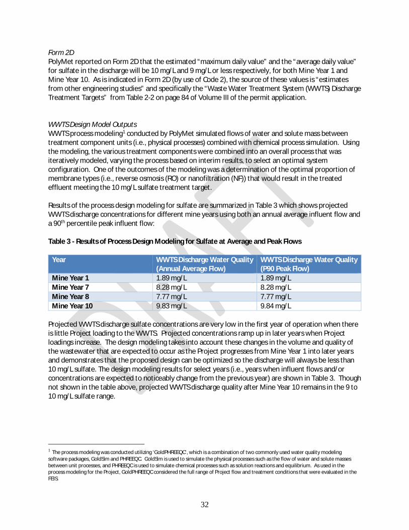
Form 2D PolyMet reported on Form 2D that the estimated “maximum daily value” and the “average daily value” for sulfate in the discharge will be 10 mg/L and 9 mg/L or less respectively, for both Mine Year 1 and Mine Year 10. As is indicated in Form 2D (by use of Code 2), the source of these values is “estimates from other engineering studies” and specifically the “Waste Water Treatment System (WWTS) Discharge Treatment Targets” from Table 2-2 on page 84 of Volume III of the permit application. WWTS Design Model Outputs WWTS process modeling1 conducted by PolyMet simulated flows of water and solute mass between treatment component units (i.e., physical processes) combined with chemical process simulation. Using the modeling, the various treatment components were combined into an overall process that was iteratively modeled, varying the process based on interim results, to select an optimal system configuration. One of the outcomes of the modeling was a determination of the optimal proportion of membrane types (i.e., reverse osmosis (RO) or nanofiltration (NF)) that would result in the treated effluent meeting the 10 mg/L sulfate treatment target. Results of the process design modeling for sulfate are summarized in Table 3 which shows projected WWTS discharge concentrations for different mine years using both an annual average influent flow and a 90th percentile peak influent flow: Table 3 - Results of Process Design Modeling for Sulfate at Average and Peak Flows
Year WWTS Discharge Water Quality (Annual Average Flow)
WWTS Discharge Water Quality (P90 Peak Flow)
Mine Year 1 1.89 mg/L 1.89 mg/L Mine Year 7 8.28 mg/L 8.28 mg/L Mine Year 8 7.77 mg/L 7.77 mg/L Mine Year 10 9.83 mg/L 9.84 mg/L
Projected WWTS discharge sulfate concentrations are very low in the first year of operation when there is little Project loading to the WWTS. Projected concentrations ramp up in later years when Project loadings increase. The design modeling takes into account these changes in the volume and quality of the wastewater that are expected to occur as the Project progresses from Mine Year 1 into later years and demonstrates that the proposed design can be optimized so the discharge will always be less than 10 mg/L sulfate. The design modeling results for select years (i.e., years when influent flows and/or concentrations are expected to noticeably change from the previous year) are shown in Table 3. Though not shown in the table above, projected WWTS discharge quality after Mine Year 10 remains in the 9 to 10 mg/L sulfate range. 1 The process modeling was conducted utilizing ‘GoldPHREEQC’, which is a combination of two commonly used water quality modeling software packages, GoldSim and PHREEQC. GoldSim is used to simulate the physical processes such as the flow of water and solute masses between unit processes, and PHREEQC is used to simulate chemical processes such as solution reactions and equilibrium. As used in the process modeling for the Project, GoldPHREEQC considered the full range of Project flow and treatment conditions that were evaluated in the FEIS.

33
Pilot Test Results To demonstrate that membrane treatment technologies are actually capable of achieving a 10 mg/L sulfate treatment target, PolyMet conducted a 6-month pilot testing program using seepage water from the existing tailings basin. For a portion of the test, additional metals were added to the test influent to more closely simulate projected influent quality. Pilot treatment system design included both RO and NF (in this case, ”vibratory shear-enhanced process” or “VSEP”) components. Results of the pilot testing are shown in Figure 9 which is reproduced from the ”Final Pilot Testing Report” (Appendix B of the “Waste Water Treatment System: Design and Operation Report, v2, October 2017”). Figure 9 – Sulfate Removal by the RO Process
The figure shows that influent for the pilot test, consisting of a mixture of tailings basin surface seepage collected from monitoring station SD004 (blue diamonds in the figure above) and groundwater seepage collected from a new well located at the toe of the basin near monitoring well GW006 (red squares), varied from approximately 100 to 500 mg/L sulfate. The figure also shows the permeate (i.e., effluent) concentration of both the RO and VSEP (NF) processes. Effluent from the RO process was consistently less than 1 mg/L sulfate (purple circles above) and the VSEP effluent was clustered in the 10-25 mg/L sulfate range (aqua-colored Xs). PolyMet will be operating both an RO circuit and an NF circuit at the WWTS and will blend the two permeates at a ratio based on actual concentrations to remain below the 10 mg/L Operating Limit. The blending of permeates to achieve an overall discharge concentration of

34
10 mg/L sulfate is proposed because of energy use considerations, reductions in the volume of concentrate, minimized cycling-up of rejected constituents and reduced membrane fouling. Discussion PolyMet has selected a combined water management and wastewater treatment system that will minimize or eliminate (i.e., to a level below method detection limit in most cases) pollutant loading to the receiving waters. The selected design utilizes the proven technologies of mechanical filtration followed by reverse osmosis and nanofiltration membrane filtration and has been demonstrated to be effective in project-specific pilot testing. None of the receiving waters is subject to the Class 4A standard of 10 mg/L for sulfate, which applies to “water used for production of wild rice.” Minn. R. 7050.0224 subp. 2. Based on information available at the time of the FEIS, including the recommended wild rice water listings made by MPCA staff in 2012 for certain portions of the Embarrass and Partridge Rivers, some waters downstream of the WWTS discharge might be considered “water used for the production of wild rice.” These staff recommendations, however, were not enacted into any rule or otherwise finalized. Rather, MPCA has undertaken the wild rice studies mandated by the Legislature in its recent wild rice laws. The Reasonable Potential analysis must consider the effect of dilution. 40 C.F.R. § 122.44(d)(1)(ii). The current wild rice sulfate standard is unique among Minnesota water quality standards in that it applies only in a “water used for the production of wild rice,” without necessarily being limited to the receiving water or point of discharge. For scenarios where the standard might apply at some distance downstream from the discharge, the analysis must account for watershed dilution when assessing whether the discharge would exceed the standard at the downstream location. The existing wild rice rule does not specify the averaging period over which the sulfate standard applies, nor has MPCA developed a protocol for determining if a water is impaired with respect to this use. However, ongoing research conducted as part of the MPCA’s standard revision process suggests that an appropriate averaging period for protecting the use of wild rice as a food source for wildlife and humans is a calendar year. The issues above create uncertainties in conducting a Reasonable Potential analysis. In this case, however, the MPCA did not need to address these uncertainties because the projected effluent quality end-of-pipe at the WWTS will not exceed 10 mg/L and therefore will not cause an exceedance of the sulfate standard at downstream locations. Specifically, the controlling design criterion for WWTS discharges is that the combined water management and treatment system consistently achieves a sulfate concentration of 10 mg/L or less in the discharge (Section 3.1.1 on pp. 19-20 of the Antidegradation Evaluation). The results of the design modeling and the pilot testing support the sulfate values reported in Form 2D. The results indicate that the treatment system will be designed and operated (including managing the proportion of RO to NF treatment) to consistently achieve a specified treatment target concentration. In this case, that target for sulfate is a performance Operating Target of 9 mg/L or less. Membrane treatment technologies such as RO and NF work the same way as a micro-filter, in that a membrane has microscopic holes that allow the water molecules to pass through but retain the targeted constituent on one side of the membrane. This rejected water containing the concentrated constituents will be routed to the chemical precipitation treatment chain of the WWTS where the precipitation process results in the removal of the constituents from the system as a waste solid.

35
A membrane rejects molecules primarily based on molecular size and charge. As size and charge of the molecule increase, the membrane tends to reject the molecules to a greater extent. The properties of a membrane, such as the size of the pores, can be selected as part of treatment facility design to maximize removal of a particular constituent. In this case, the sulfate rejection rate across the membranes to be utilized in the WWTS was calculated to be >99% based on the results of pilot testing. Designing membrane treatment systems to achieve a specified effluent concentration is an established and reliable engineering process. Because the maximum concentration of the discharge from the WWTS is projected to be no greater than 10 mg/L, and the annual average is projected to be 9 mg/L or less, there is no reasonable potential for the discharge to exceed the wild rice standard for sulfate regardless of where that standard may be applicable in any downstream waters. EPA’s NPDES permit writer’s manual states that if the projected effluent concentration is equal to or less than the applicable water quality standard, there is no reasonable potential and no need to require WQBELs for the discharge. During the environmental review process, PolyMet voluntarily committed to treating Project wastewater to 10 mg/L sulfate prior to discharge given the current wild rice rules and rulemaking process currently underway. This commitment to meet a 10 mg/L sulfate concentration in the discharge eliminates questions about applicability of the current wild rice standard at downstream locations. While voluntary, the commitment served as the basis for the water quality effects analysis in the FEIS. The incorporation of wastewater treatment technologies capable of achieving a 10 mg/L sulfate treatment level is a fundamental component of the overall Project design as evaluated in the FEIS and as described in the NPDES/SDS permit application; it is not a mitigation that was added as part of the permitting process. To ensure the WWTS is operating as designed and to remain consistent with the assumptions made in the FEIS, the permit includes an internal performance monitoring point (Station WS074) where an Operating Limit of 10 mg/L sulfate applies. The Operating Limit at WS074 is an enforceable permit limit but is neither a water quality based effluent limit nor a technology based effluent limit because there is no Reasonable Potential. Station WS074 will be located within the internal waste stream at a point after the permeates from the reverse osmosis and nanofiltration processes mix and prior to where the resulting blended effluent enters the stabilization process before it is discharged. Under the permit conditions, no sulfate may be added to the treated wastewater during the effluent stabilization process (i.e., between the internal monitoring point of WS074 and Outfall SD001). The Operating Limit for total sulfate is an enforceable permit condition, and if it were exceeded, it would be a violation of this permit. As the FEIS discussed, if Minnesota adopts a revised wild rice standard, any subsequent Reasonable Potential analysis would have to be calculated using the revised standard. However, because the outcome of the wild rice rulemaking is not yet determined, MPCA has evaluated against the existing 10 mg/L sulfate standard. This is protective of any downstream locations where the standard may apply, and this analysis demonstrates that Project discharges do not have a reasonable potential to cause or contribute to a violation of the 10 mg/L sulfate standard for wild rice. Copper MPCA conducted a Reasonable Potential analysis for copper using the sources described above. Based on its review, the Agency has determined there is no reasonable potential for concentrations of copper to cause or contribute to an exceedance of any applicable water quality standards.

36
Form 2D PolyMet reported on Form 2D of the permit application that the estimated copper concentration in the discharge from the WWTS would have a “maximum daily value” of 9.3 µg/L and an “average daily value” of 5.3 µg/L for Mine Year 1; and an estimated “maximum daily value” of 9.3 µg/L and an “average daily value” of 9 µg/L for Mine Year 10. EPA Form 2D indicates the source of these values is “estimates from other engineering studies” and specifically the “Waste Water Treatment System (WWTS) Discharge Treatment Targets” from Table 2-2 on page 84 of Volume III of the permit application. WWTS Design Model Outputs Copper was included as one of the evaluated constituents in the WWTS process modeling described for sulfate above. This modeling indicated that optimization of the treatment process for sulfate also resulted in effluent concentrations for copper well below applicable standards, as shown in the Table 4. Table 4 - Copper Effluent Quality
Year Effluent Water Quality (Annual Average Flow)
Effluent Water Quality (P90 Peak Flow)
Mine Year 1 0.00657 µg/L 0.00657 µg/L Mine Year 7 0.174 µg/L 0.174 µg/L Mine Year 8 0.533 µg/L 0.533 µg/L Mine Year 10 0.874 µg/L 0.874 µg/L Water Quality Standard* 9.3 µg/L 9.3 µg/L
*At hardness = 100 mg/L Pilot Test Results PolyMet conducted a 6-month pilot testing program using seepage water from the existing tailings basin. For a portion of the test, additional metals were added to the test influent to more closely simulate projected influent quality. Pilot treatment system design included both RO and NF (In this case, “vibratory shear-enhanced process” or “VSEP”) components. Results of the pilot testing are shown in Figure 10 which is reproduced from data found in the ‘Final Pilot Testing Report’ (Appendix B of the “Waste Water Treatment System: Design and Operation Report, v2, October 2017”). This is the same pilot testing used for the sulfate results described above, and the treatment was operated to meet the sulfate target of 10 mg/L.

37
Figure 10 - Copper Removal by RO Process
The figure shows that influent to the pilot test, consisting of a mixture of tailings basin surface seepage collected from monitoring station SD004 (blue diamonds in the figure above) and groundwater seepage collected from a new well located at the toe of the basin near monitoring well GW006 (orange colored X’s), varied from approximately 0.5 µg/L to 46 µg/L copper. The figure also shows the permeate (i.e., effluent) concentration of both the RO and VSEP (NF) processes. Eighty-five percent of the results for copper in the RO effluent were less than the laboratory detection limit of 0.5 µg/L, and all detected values were less than 1.5 µg/L (blue colored X’s above). Copper concentrations in the VSEP effluent were clustered in the 0.5 – 3.1 µg/L copper range (gray triangles). PolyMet will be operating both an RO circuit and an NF circuit at the WWTS and will blend the two permeates at a ratio based on actual concentrations to consistently meet the 10 mg/L sulfate treatment target, which was the target for the pilot testing described above. By meeting the 10 mg/L sulfate treatment target, the facility will also meet the 9.3 µg/L treatment target for copper as shown above. Operating Limit for Copper To ensure PolyMet operates its WWTS as proposed to meet an internal performance Operating Limit of 10 mg/L for sulfate, the Agency is requiring an internal performance monitoring station at Station WS074. (The Operating Limit for sulfate is further discussed in the Internal Performance Monitoring section of this Fact Sheet.) This internal monitoring station will be located within the WWTS at a point after the permeate streams from the RO and NF processes are blended and prior to effluent stabilization. The draft permit also includes a monthly average Operating Limit of 9.3 µg/L total copper at Station WS074. The Operating Limit is based on a projected hardness of approximately 100 mg/L in the effluent. No copper may be added to the treated wastewater during the effluent stabilization process (i.e., between the internal monitoring point of WS074 and Outfall SD001). This Operating Limit for total copper is an enforceable permit condition, and if it were exceeded, it would be a violation of this permit.

38
As described above, the analysis of copper showed there is no reasonable potential for copper to cause or contribute to an exceedance of water quality standards in the receiving waters, and therefore, there is no need to require WQBELs for the discharge. However, in addition to the internal Operating Limit at Station WS074, the draft permit contains federally-required Technology Based Effluent Limits (TBELs) relating to copper based on the New Source Performance Standards (NSPS) in 40 CFR § 440.104. The applicable TBEL under the NSPS is a daily maximum of 300 µg/L and a monthly average of 150 µg/L. at SD001. Metals and Other Parameters of Concern The degree of treatment necessary to accomplish an effluent concentration of 10 mg/L sulfate in the discharge from the WWTS will also result in the effective removal of other parameters of concern from the wastewater. As stated above, membrane treatment works the same way as a filter, in that a membrane has microscopic holes that allow the water molecules to pass through but retain the targeted constituent on one side of the membrane. A membrane rejects molecules primarily based on molecular size and charge. As size and charge of the molecule increase, the membrane tends to reject the molecules to a greater extent. The sulfate rejection rate across the membranes to be utilized in the WWTS was calculated to be >99% based on the results of pilot testing. The sulfate rejection rate is comparable to the rejection rate of other parameters of concern such as heavy metals because of their size and/or charge. Thus, treating sulfate to low levels (< 10 mg/L) will necessarily treat the other parameters of concern to low levels as well. So long as sulfate remains at or below 10 mg/L, the WWTS will ensure other parameters are discharged at below the projected design model concentrations. MPCA conducted a Reasonable Potential evaluation for a variety of metals in addition to copper and for other parameters of concern, such as those subject to Class 3 and Class 4 water quality standards. As with sulfate and copper, the analysis indicated that there is no reasonable potential to exceed the water quality standard applicable to each parameter in the receiving waters. The design modeling values and the pilot testing results for all of the parameters of concern are below their respective water quality standards. Therefore, no WQBELs are required for any of these metals or parameters of concern at Outfall SD001. However, for those parameters subject to federal categorical standards in 40 CFR 440 (i.e. copper, zinc, lead, mercury, cadmium, pH, total suspended solids, and arsenic), the applicable TBELs will be required at Outfall SD001.

39
Proposed Permit Limits Technology Based Effluent Limits Minn. R. 7053.0225 subp. 1(A) states, in part, that point source dischargers of industrial or other wastes must comply with all applicable federal standards adopted by the EPA under sections 301, 306, and 307 of the Clean Water Act, United States Code, title 33, sections 1311, 1316, and 1317. Code of Federal Regulations, title 40, parts 401 through 469, are incorporated by reference. Section 301 of the Clean Water Act requires particular categories of industrial dischargers to meet technology-based effluent limitation guidelines. Effluent limitation guidelines are national regulatory standards for wastewater discharged to surface waters and municipal sewage treatment plants. EPA issues these regulations for industrial categories, based on the performance of treatment and control technologies Technology-based effluent limitations (TBELs) require a minimum level of treatment of pollutants for point source discharges based on available treatment technologies, while allowing the discharger to use any available control technique to meet the limits. For industrial facilities, TBELs are derived by:
· Using national effluent limitations guidelines (ELGs) and standards established by EPA, and/or · Using best professional judgement (BPJ) on a case-by-case basis in the absence of national
guidelines and standards. PolyMet is proposing to construct and operate a mine for copper-nickel-platinum-group elements (PGE) and associated processing facilities. The applicable ELG for the NorthMet Project is 40 CFR 440 – Ore Mining and Dressing Point Source Category. EPA promulgated the Ore Mining and Dressing Effluent Guidelines and Standards (40 CFR Part 440) in 1975, and amended the regulation in 1978, 1979, 1982 and 1988. The regulation covers wastewater discharges from ore mines and processing operations. Regulations in Subpart J (Copper, Lead, Zinc, Gold, and Molybdenum), Subpart G (Nickel) and K (Platinum Ores) are applicable to the Project. New Source Performance Standards (NSPS) defined at CWA section 306, apply to direct dischargers. NSPS are technology-based standards for facilities that qualify as new sources as defined in 40 CFR § 122.2 and 40 CFR § 122.29. These standards reflect effluent reductions that are achievable based on the “best available demonstrated control technology.” 40 CFR § 440.104 contains the NSPS for mines regulated under Subpart J. The Project is considered a new source, and mine drainage discharged from SD001 via SD002 – SD011 is subject to the TBELs in 40 CFR § 440.104. For direct dischargers, best professional judgement (BPJ) may be used to establish technology-based limits or determine other appropriate means to control its discharge. BPJ is the method used to develop technology-based NPDES permit conditions on a case-by-case basis using all reasonably available and relevant data to establish technology-based limits or determine other appropriate means to control its discharge. It was determined upon review of the ELGs found in 40 CFR § 440, that Subpart G and Subpart K apply in addition to Subpart J discussed above, however, there are no NSPS for Subparts G and K.

40
A summary of TBELs applicable to the proposed Project follows:
· Subpart J: 40 CFR § 440.104 states facilities that qualify as new sources and are subject to New Source Performance Standards (NSPS) must achieve the NSPS representing the degree of effluent reduction attainable by application of the best available demonstrated technology (BADT). Effluent limits applicable to NSPS were evaluated and as a result, the draft permit contains TBELs for copper, lead, mercury, cadmium, pH, and total suspended solids based on Subpart J requirements.
· Subpart G: 40 CFR § 440.72 describes effluent limitations representing the degree of effluent
reduction attainable by the application of the best practicable control technology currently available (BPT). There are no NSPS for Subpart G. Effluent limits applicable to BPT were evaluated against the NSPS effluent limits required by Subpart J. As a result, the draft permit contains a TBEL for zinc and arsenic based on Subpart G requirements.
· Subpart K: 40 CFR § 440.113 describes effluent limitations representing the degree of effluent
reduction attainable by the application of the best available technology economically achievable (BAT). There are no NSPS for Subpart K. Effluent limits applicable to BAT were evaluated against the NSPS effluent limits required by Subpart J. As a result, the draft permit contains a TBEL for zinc based on Subpart K requirements. (The TBEL for zinc required by Subpart K is the same as the TBEL required under Subpart G).
Effluent characteristics were compared against each other for the Subpart J, Subpart G, and Subpart K categories. By using BPJ, the most stringent value for each parameter was chosen and will be the applicable TBEL for the discharge at SD001. A summary of the effluent characteristics for each subpart is found in Tables 5 and 6. Table 5 - Summary of Effluent Characteristics for Subpart J, Subpart G and Subpart K Categories
Effluent Characteristic
Subpart J NSPS Monthly Avg (mg/L)
Subpart J NSPS Daily Max (mg/L)
Subpart G BPT Monthly Avg (mg/L)
Subpart G BPT Daily Max (mg/L)
Subpart K BAT Monthly Avg (mg/L)
Subpart K BAT Daily Max (mg/L)
Copper 0.15 0.30 0.15 0.30 0.15 0.30 Zinc 0.75 1.5 0.5 1.0 0.5 1.0 Lead 0.3 0.6 N/A N/A 0.3 0.6 Mercury 0.001 0.002 N/A N/A 0.001 0.002 Cadmium 0.05 0.10 0.05 0.10 0.05 0.10 pH * * * * N/A N/A TSS 20.0 30.0 20 30 N/A N/A Arsenic 0.5 1.0 N/A N/A
** 6.0 – 9.0 SU The draft permit contains monthly average and daily maximum TBELs for the parameters listed below applicable to the discharge at SD001, after effluent stabilization. Monitoring of the effluent for these parameters is required once per week.

41
Table 6 - Applicable Categorical Technology Based Effluent Limitations
Substance or Characteristic
Calendar Month Average (mg/L)
Daily Maximum mg/L)
Basis for Limit (BAT,BCT,BPJ,BPT,NSPS)*
Copper 0.15 0.30 NSPS, BPT, BAT Zinc 0.5 1.0 BPT, BAT, BPJ Lead 0.3 0.6 NSPS, BPT, BAT Mercury 0.001 0.002 NSPS, BAT Cadmium 0.05 0.10 NSPS, BPT, BAT pH 6.0 - 9.0 NSPS, BPT TSS 20.0 30.0 NSPS, BPT Arsenic 0.5 1.0 BPT, BPJ
*NSPS: 40 CFR 440.104; BPT: 40 CFR 440.72; BAT: 40 CFR 440.113 Comparison of Technology Based Effluent Limit to Equivalent Secondary Treatment Standards – TSS and pH The effluent limitation for total suspended solids (TSS) is a technology based effluent limit contained in the NSPS as described in 40 CFR § 440.104. The maximum daily limit specified for total suspended solids is 30 mg/L. The monthly average effluent limit for total suspended solids is 20 mg/L. The equivalent state secondary treatment standard under Minn. R. 7053.0215 (as incorporated by Minn. R. 7053.0225) requires a maximum daily limit of 45 mg/L and a monthly average limit of 30 mg/L. The TBEL is more stringent than the state secondary standard; therefore, the average and maximum TBEL limits of 20 mg/L and 30 mg/L respectively apply. The effluent limitation of 6.5 to 8.5 for pH are based on state water quality standards for Class 2B (aquatic resources) and Class 4A (agriculture and wildlife) waters, in accordance with Minn. R. 7050.0222 and Minn. R. 7050.0224, for effluent, which is the principal source contributing flow to the receiving waters (i.e. headwaters). The state water quality based effluent limitation of 6.5-8.5 is more stringent than the TBELs of 6.0 to 9.0 for pH set forth in 40 CFR § 440.72 and 40 CFR § 440.104; therefore, the 6.5-8.5 value is included as the pH limit in the draft permit for the effluent at SD001. Metals Copper A Reasonable Potential analysis for copper was conducted by MPCA as described in the Reasonable Potential section above. Based on its review, the Agency has determined there is no reasonable potential for concentrations of copper to cause or contribute to an exceedance of water quality standards. However, to ensure the WWTS operates as proposed, there is an internal performance limit for copper at Station WS074. The internal monitoring station will be established within the WWTS at a point located after the permeate streams from the reverse osmosis and the nanofiltration are blended and prior to effluent stabilization. No copper may be added to the treated wastewater during the effluent stabilization process (i.e., between the internal monitoring point of WS074 and Outfall SD001). The draft permit contains a monthly average Operating Limit of 9.3 µg/L total copper at Station WS074. The Operating Limit is based on a projected hardness of approximately 100 mg/L in the effluent. In addition to the internal Operating Limit for copper at station WS074, the draft permit contains a TBEL based on the NSPS under 40 CFR § 440.104. Weekly monitoring of the effluent at SD001 for total copper

42
using EPA Method 200.8 is required by the draft permit and the applicable TBEL under the NSPS is a daily maximum of 0.30 mg/L and a monthly average of 0.15 mg/L. Lead A Reasonable Potential analysis for lead was conducted as part of the permit application review. Based on its review, the Agency has determined there is no reasonable potential for concentrations of lead to cause or contribute to an exceedance of water quality standards. The draft permit requires weekly monitoring of the effluent at SD001 for total lead. The applicable TBEL under the NSPS for lead is a daily maximum of 0.6 mg/L and a monthly average of 0.3 mg/L. Mercury A Reasonable Potential analysis for mercury was conducted as part of the permit application review. Based on its review, the Agency has determined there is no reasonable potential for concentrations of mercury to cause or contribute to an exceedance of water quality standards. The MPCA expects no measurable change in mercury concentrations downstream in the St. Louis River at Forbes or below. The draft permit requires weekly monitoring of the effluent at SD001 for total mercury using analytical method 1631 and clean-sampling method 1669. The applicable TBEL under the NSPS for mercury is a daily maximum of 0.002 mg/L and a monthly average of 0.001 mg/L. Cadmium A Reasonable Potential analysis for cadmium was conducted as part of the permit application review. Based on its review, the Agency has determined there is no reasonable potential for concentrations of cadmium to cause or contribute to an exceedance of water quality standards. The draft permit requires weekly monitoring of the effluent at SD001 for total cadmium. The applicable TBEL under the NSPS for cadmium is a daily maximum of 0.10 mg/L and a monthly average of 0.05 mg/L. Zinc and Arsenic A Reasonable Potential analysis for zinc and arsenic was conducted as part of the permit application review. Based on its review, the Agency has determined there is no reasonable potential for concentrations of zinc or arsenic to cause or contribute to an exceedance of water quality standards. There is no applicable TBEL under the NSPS for zinc or arsenic as described in Table 2 above. A review of effluent limit requirements under 40 CFR § 440 Subpart G and Subpart K were conducted and compared to the NSPS under 40 CFR § 440.104. The review determined that applicable TBELs for application of the best practicable control technology currently available (BPT) are required for zinc under 40 CFR § 440.72 and 40 CFR § 440.113; TBELs for arsenic are applicable under 40 CFR § 440.113 by applying the best available technology economically achievable (BAT). Using best professional judgement (BPJ), the Agency determined the applicable effluent limits for zinc and arsenic are a daily maximum of 1.0 mg/L and a monthly average of 0.5 mg/L. Weekly monitoring of zinc and arsenic at SD001 is required by the draft permit.
43
Internal Performance Monitoring Sulfate and Copper Internal Performance Evaluation Point As described above, MPCA has determined that there is no reasonable potential for sulfate or copper to cause or contribute to a violation of a water quality standard, and is not establishing a WQBEL for either parameter. However, PolyMet has proposed using sulfate and copper as indicator parameters for ongoing evaluation of the performance of the WWTS tailings basin seepage treatment train as explained in more detail in Application Volume I, Appendix D. By meeting its treatment targets for sulfate and copper, PolyMet will be able to assure that the discharge will have no reasonable potential for any parameters of potential concern. To facilitate this approach to evaluating the performance of the WWTS, Operating Targets and Operating Limits for sulfate and copper are included in the draft permit. PolyMet will sample for sulfate and copper at an internal performance monitoring point established within the WWTS at a point located after the permeate streams from the reverse osmosis and the nanofiltration membranes are blended and prior to effluent stabilization (monitoring station WS074). These details are discussed below. Sulfate The Project WWTS will eliminate (i.e., to a level below the method detection limit) or minimize pollutant loading to the receiving waters. The removal of sulfate is the controlling factor in the treatment system design. The WWTS incorporates membrane treatment technology (a combination of nanofiltration and reverse osmosis) designed to achieve an effluent concentration of 10 mg/L sulfate or less. The MPCA conducted a Reasonable Potential analysis for sulfate in the Project’s proposed discharge from the WWTS. In the absence of actual effluent data (the facility is proposed at this point and is not actually built), the MPCA considered the proposed point and nonpoint source controls including the treatment technologies proposed. Specifically, the following information was reviewed: 1) estimated effluent quality reported on Form 2D in the “NPDES/SDS Permit Application, Volume III, October 2017 (updated)”; 2) WWTS design model outputs as described in Attachment H to the “Waste Water Treatment System: Design and Operation Report, v2, October 2017” (WWTS Report) cited as a reference in the NPDES/SDS Permit Application dated October 2017; and 3) the Final Pilot Testing Report, included as Attachment B to the WWTS Report for the proposed project. The MPCA determined there is no reasonable potential for the discharge to cause or contribute to an exceedance of an applicable sulfate standard, and therefore, no justification for a WQBEL for sulfate to be included in the draft permit. By treating sulfate levels to 10 mg/L or less, all other parameters will be treated to concentrations less than their respective water quality standard. In doing so, the design values for parameters of concern as indicated in the permit application based on modeling data and pilot test data will be consistently below the water quality standards. The WWTS design to treat discharges to a concentration level of 10 mg/L for sulfate was included in the environmental effects analysis described in the FEIS. To ensure the WWTS is operating as designed and to remain consistent with the assumptions of the FEIS, the permit includes an internal performance monitoring point at Monitoring Station WS074 where an Operating Limit of 10 mg/L sulfate applies. The Operating Limit at WS074 is an enforceable permit limit but is neither a WQBEL nor a TBEL because it is an internal performance metric within the WWTS. To effectively monitor the degree and quality of

44
wastewater treatment afforded by the membrane technologies, Station WS074 will be located within the internal waste stream at a point after the permeates from the reverse osmosis and nanofiltration processes mix and prior to where the resulting blended effluent enters the stabilization process before it is discharged. This point within the treatment system flowsheet is immediately after the treatment processes that result in the removal of sulfate and is therefore representative of the water entering the stabilization process. The draft permit contains a prohibition against adding sulfate during the subsequent effluent stabilization process and a requirement that this be certified on the monthly Discharge Monitoring Reports. Conformance with the Operating Limit will be determined by an average of the previous 12-monthly averages. Based on research from MPCA’s work in connection with the proposed revisions to the wild rice sulfate water quality standard, this averaging period is protective against longer-term chronic effects to wild rice (Statement of Need and Reasonableness: proposed amendment of the sulfate water quality standard applicable to wild rice and identification of wild rice waters. Minn. R. ch. 7050 and 7053, July 2017). To ensure that the Operating Limit of 10 mg/L is not exceeded, the permit will also include an internal Operating Target value at Station WS074 of 9 mg/L as determined by a monthly average. The Operating Target value is defined as an intervention metric that triggers adaptive management as defined in a pre-approved Sulfate Reduction Evaluation Plan to ensure that the Operating Limit of 10 mg/L is not exceeded. The Sulfate Reduction Evaluation Plan must be approved by MPCA before operation and discharge from the WWTS. Copper A Reasonable Potential analysis was conducted for a wide range of metals (aluminum, arsenic, antimony, boron, cobalt, cadmium, chromium, copper, lead, nickel, selenium, silver, thallium and zinc) based on available data submitted with the permit application. This information included estimated effluent quality data reported in EPA Form 2D, results from the pilot testing of the proposed wastewater treatment technology, modeling projections from the FEIS and design engineering modeling conducted after the FEIS. Based on the available data, there is no reasonable potential for the discharge to cause or contribute to an exceedance for any of the metals, including copper. Therefore, there is no justification for a WQBEL for copper or other metals to be included in the permit. A more thorough discussion of the reasonable potential evaluation process as it is applied to the Project’s discharge can be found in the Reasonable Potential section of this Fact Sheet above. As described above, the WWTS is designed to treat sulfate to a concentration of 10 mg/L or less. The degree of treatment necessary to accomplish an effluent concentration of 10 mg/L sulfate will also result in the effective removal of other parameters of concern, including metals, to concentrations below their respective water quality standards. As described in the Reasonable Potential section of this Fact Sheet, treating sulfate to low levels (10 mg/L or less) will treat many other parameters of concern to low levels as well. However, to provide assurance of this fact, the permit also includes an internal performance Operating Limit for total copper. Copper is the particular metal focused on for an internal Operating Limit based on the waste rock characterization and wastewater modeling projections conducted for the Project. Being a copper mine, concentrations in the internal wastewater stream relative to the applicable chronic standard are expected to be greater for copper than a similar comparison for other metals. The WWTS membrane technologies employ similar removal processes and efficiencies for copper as they do for other metals with less sensitive water quality standards. Therefore, including an Operating Limit based on the chronic aquatic life standard for copper, in combination with the 10 mg/L Operating Limit for sulfate, will be indicative that the chronic aquatic life standards for others metals are met as well.

45
The draft permit includes a monthly average Operating Limit of 9.3 µg/L total copper at internal monitoring station WS074. As noted above, Station WS074 is located within the internal waste stream at a point after the permeate from the reverse osmosis and nanofiltration processes mix and prior to where the resulting blended effluent enters the stabilization process before it is discharged. An exceedance of the Operating Limit for copper is a violation of the permit. To ensure the copper concentration measured at Station WS074 is representative of the discharge of treated effluent through Outfall SD001, the draft permit contains a prohibition against adding copper during the effluent stabilization process (i.e., between monitoring Station WS074 and Outfall SD001). In addition to the Operating Limit described above, PolyMet is required to meet TBELs for total copper as required by 40 CFR pt. 440 Subpart J. The draft permit contains a monthly average effluent limit of 0.15 mg/L and a daily maximum effluent limit of 0.30 mg/L for total copper to be applied at monitoring station SD001 (end of pipe). TBELs for other constituents are discussed in the Proposed Permit Limits section of this Fact Sheet above.

46
Proposed Monitoring Group Summary Monitoring Group Summary For the purposes of providing an overall summary of the water quality monitoring required by the draft permit, the parameters to be monitored at the various locations at the Mine and Plant Sites can be generally categorized into three monitoring groups: Group A, Group B and Group C. The selection of which group of parameters would be required at individual monitoring locations was based on the expected nature of the water to be monitored and the purpose of the monitoring. These three groups of parameters are not necessarily uniformly applied and certain parameters are added or deleted from each group based on the specific characteristics and purpose of the individual monitoring location.
· Group A Monitoring Summary Group A parameters are generally indicative of mining activities. The purpose of Group A monitoring is to facilitate more frequent monitoring of a focused group of parameters at certain key locations to identify potential water quality impacts in the most timely manner practicable. If potentially problematic results are seen, additional monitoring can be conducted as appropriate. Group A parameters include chloride, sulfate, specific conductance, and total dissolved solids and are summarized in Table 7.
Table 7 - Group A Monitoring Parameters
Parameters Chloride Specific Conductance Sulfate Total Dissolved Solids (TDS)
· Group B Monitoring Summary
Group B parameters consist of those with TBEL requirements specified in 40 CFR part 440 as well as those subject to Class 3 & 4 water quality standards in Minnesota Rule 7050.0223 and 7050.0224. Group B monitoring also includes additional parameters of interest particular to the Project. The list of Group B parameters is intended to include those parameters that are expected to be monitored routinely for the purpose of assessing facility compliance and potential impacts. A summary of typical Group B parameters is listed in Table 8. Table 8 - Group B Monitoring Parameters
ELGs Class 3 & 4 Other/Indicator
Arsenic Chloride Aluminum Cadmium Bicarbonate Calcium Copper Hardness Cobalt Lead Specific Conductance Magnesium Mercury Sulfate Nickel pH Total Dissolved Solids (TDS) Total Suspended Solids (TSS) Zinc

47
· Group C Monitoring Summary Group C parameters consist of the Group B parameters plus additional metals and other inorganic pollutants. The Group C parameters include a wider list of metals for which less frequent monitoring is appropriate. A summary of typical Group C parameters is listed in Table 9. Table 9 - Group C Monitoring Parameters
ELGs Class 3 & 4 Metals & Inorganics Arsenic Chloride Antimony Cadmium Bicarbonate Aluminum Copper Boron Beryllium Lead Hardness Boron Mercury Specific Conductance Calcium pH Sulfate Chromium Total Suspended Solids (TSS) Total Dissolved Solids (TDS) Cobalt Zinc Fluoride Magnesium Manganese Nickel Selenium Silver Sodium Thallium

48
Wastewater Treatment System Monitoring The WWTS will be located at the Plant Site and will house the process equipment for two separate treatment trains known as the mine water treatment trains and the tailings basin seepage treatment train. The primary components of the WWTS for the Project will include the Equalization Basin Area located at the Mine Site, the Mine to Plant Pipelines (MPP), and the WWTS building and associated Pretreatment Basin. The WWTS building will house the mine water treatment systems and the tailings basin seepage treatment system. WWTS – Surface Water Discharge Monitoring The compliance monitoring location for the discharge from the WWTS is located at SD001. As discussed in the Technology Based Effluent Limit Section of this Fact Sheet, the draft permit contains monthly average and daily maximum Technology Based Effluent Limits at SD001 for the parameters listed in Table 10. Table 10 - Applicable Categorical Technology Based Effluent Limitations
Substance or Characteristic Calendar Month Average (mg/L) Daily Maximum (mg/L) Copper 0.15 0.30 Zinc 0.5 1.0 Lead 0.3 0.6 Mercury 0.001 0.002 Cadmium 0.05 0.10 pH 6.0 SU - 9.0 SU TSS 20.0 30.0 Arsenic 0.5 1.0
Weekly monitoring for Class 3 & 4 parameters as well as nickel is also required at SD001. The draft permit requires monthly monitoring for Group C parameters. The effluent is split at SD001 to three different receiving waters via a total of 10 separate outfalls. Effluent from SD001 flows to the headwater wetlands of Unnamed Creek via SD002 and SD003. The headwater wetlands of Trimble Creek receive effluent from SD001 via outfalls SD004 – SD010. The effluent also flows to the headwaters of Second Creek via SD011. Monitoring of the flow to each of these stations is required monthly where monthly average, daily maximum, and monthly flows are required to be reported. WWTS – Internal Waste Stream Monitoring Monitoring at internal monitoring points is required at the WWTS. The monitoring is focused on internal waste streams collected at the various WWTS components prior to and after treatment and provides information on quality and sources of wastewater into the WWTS. The internal waste stream monitoring can be categorized into the following groups:
· Internal Performance Monitoring Point · Influent to WWTS (from FTB Seepage Capture Systems) · Influent to WWTS (Low Concentration Mine Water) · Influent to WWTS (High Concentration Mine Water) · Effluent from Mine Water Treatment System (Chemical Precipitation Treatment Train) · Effluent from Mine Water Treatment System (Membrane Filtration Treatment Train)
49
Internal Performance Monitoring Point An internal performance monitoring point at Station WS074 has been established in the draft permit to ensure the WWTS is operating as designed. Monitoring will be required once per week for sulfate after the permeate streams from the reverse osmosis and nanofiltration membranes are blended and prior to effluent stabilization. To ensure the WWTS is effectively removing sulfate, the draft permit includes a monthly average Operating Limit of 10 mg/L total sulfate. An exceedance of the Operating Limit for sulfate is a violation of the permit. To ensure that the WWTS is effectively removing copper, the permit includes a monthly average Operating Limit of 9.3 ug/L total copper at internal monitoring station WS074. An exceedance of the Operating Limit for copper is a violation of the permit. Further discussion on the internal performance monitoring point, as well as the Operating Limits for total sulfate and total copper can be found in the Reasonable Potential section of this Fact Sheet. WWTS Influent – FTB Seepage Capture Systems The WWTS receives flow from the FTB Seepage Containment System and the FTB South Seepage Management System and is monitored at WS015. The draft permit requires monitoring of the WWTS influent weekly for Group B parameters to determine the influent quality of wastewater coming into the WWTS. Monthly monitoring is required for Group C parameters. WWTS Influent – Low Concentration and High Concentration Mine Water Two equalization basin systems will be in place at the Mine Site. Higher strength waste streams will be directed to one system, and lower strength waste streams into the other. Water quality will be monitored prior to the contents being routed to the WWTS for treatment. Monitoring of the influent of the Low Concentration Equalization (LCEQ) Basins and High Concentration Equalization (HCEQ) Basin will be done at WS415 and WS416 respectively. Monitoring of the influent for Group B parameters is required once per month at the combined LCEQ Basins and at the HCEQ Basin. Monitoring for Group C parameters is required twice per year. WWTS Mine Water Treatment Effluent Two separate treatment trains will treat mine water prior to discharge to the FTB. The Chemical Precipitation Treatment Train will treat mine water from the High Concentration Equalization Basin, and the Membrane Filtration Treatment Train will treat mine water from the Low Concentration Equalization Basins. Effluent from the Chemical Precipitation Treatment Train and the Membrane Filtration Treatment Train will be monitored at Stations WS072 and WS073 respectively for Group B parameters once per month and Group C parameters twice per year.

50
Mine Site Monitoring Water quality and/or water level monitoring at a total of 101 monitoring locations at the Mine Site is required by the draft permit. A complete list of Mine Site monitoring for internal waste stream monitoring stations, groundwater monitoring stations, and surface water monitoring stations along with maps showing their locations is located in Attachment 1 of this Fact Sheet. A summary of the proposed monitoring requirements at the Mine Site is provided below. Mine Site – Internal Waste Stream Monitoring Summary Monitoring at internal monitoring points will be required at the Mine Site. This monitoring is focused on internal waste streams collected from Mine Site features prior to treatment and provides information on the quality and sources of wastewater at the Mine Site. The internal waste stream monitoring can be categorized into the following groups:
· Mine Pit Dewatering · Waste Rock Stockpiles · Ore Surge Pile · Overburden Storage and Laydown Area (OSLA) · Construction Mine Water Basin
Mine Pit Dewatering: Monitoring of the mine pit dewatering water will take place at a total of four mine pit dewatering sumps located at the Mine Site. The Mine Site mine pit monitoring includes dewatering locations found at the East Pit, West Pit (two locations depending on mine year), and the Central Pit. The Mine Site dewatering water is routed to the Equalization Basin Area and is required to be monitored twice per month for the Group B parameters. Waste Rock Stockpiles: Stockpile drainage collected at the permanent Category 1 Waste Rock Stockpile sumps and ponds and the temporary Category 2/3 and Category 4 Waste Rock Stockpiles sumps and ponds is routed to the Equalization Basin Area. Drainage from each of these stockpiles is required to be monitored twice per month for chloride, copper, hardness, nickel, pH, specific conductance, sulfate, and total dissolved solids. Monthly monitoring is required at each of these areas for Group B parameters. Ore Surge Pile: Drainage collected at the Ore Surge Pile is routed to the Equalization Basin Area and is required to be monitored twice per month for chloride, copper, hardness, nickel, pH, specific conductance, sulfate, and total dissolved solids. Monthly monitoring is required at each of these areas for Group B parameters. Overburden Storage & Laydown Area (OSLA) and Construction Mine Water Basin: Monitoring of runoff collected at the OSLA will be monitored for Group A parameters once per month. Because the OSLA and Construction Mine Water Basin will store materials that are not expected to release harmful constituents, a reduction in the parameter list from what is monitored at other stockpile locations is appropriate.

51
Mine Site – Groundwater Monitoring Summary The draft permit requires monitoring of the groundwater at the Mine Site as well as areas downgradient of the Mine Site. The groundwater monitoring well network at the Mine Site has been designed to gather sufficient groundwater quality and groundwater elevation data to assess the performance of the Project engineering controls and the Project’s potential for impact to groundwater resources during both operation and reclamation/closure. The groundwater data will also be used to help predict the potential for impact to surface waters of the State which the groundwater may affect. The Mine Site groundwater monitoring well network consists of 78 monitoring devices located in and around Mine Site facilities. The monitoring network includes 43 surficial aquifer monitoring wells, 21 bedrock monitoring wells and 14 piezometers (for water level measurements) which can be categorized into the following groups:
· Category 1 Stockpile Groundwater Containment System Wells & Piezometers · Surficial Aquifer Wells · Bedrock Wells · North Flow Path Wells
Category 1 Stockpile Groundwater Containment System Wells & Piezometers: The performance of the Groundwater Containment System surrounding the Category 1 Waste Rock Stockpile will be monitored using paired monitoring devices located along the containment system at the toe of the stockpile. Each monitoring pair will include one device located on the inward side of the containment system and one on the outward side. The monitoring system will include alternating pairs of monitoring wells (from which water quality and water level samples can be obtained) and piezometers (for water level measurements only). The water level data will be used to confirm that an inward hydraulic gradient is maintained, thereby demonstrating that no leachate is leaving the stockpile groundwater containment system and entering the surficial aquifer. Water quality data will be used to compare the water chemistry from the inside of the containment system to the outside and will serve as an early indicator of any potential release of contaminants to the surrounding groundwater. Together, the Groundwater Containment System monitoring network will consist of 12 surficial aquifer monitoring wells (6 pairs) and 14 piezometers (7 pairs). The monitoring wells will be installed in the surficial aquifer and are required to be monitored monthly for water level and quarterly for Group A parameters. Surficial Aquifer and Bedrock Wells: The performance of the engineered liner systems under the temporary Category 2/3 and Category 4 Waste Rock Stockpiles, the Ore Surge Pile (OSP), and the Equalization Basins will be monitored by a total of 6 surficial aquifer monitoring wells. Each well will be immediately downgradient of these facilities, including 3 wells downgradient of the Category 2/3 Stockpile, one well downgradient of the Category 4 Stockpile, one well downgradient of the OSP, and one well downgradient of the Equalization Basins. Water quality data from these wells, in conjunction with water quality and water volume data collected from stockpile sumps, will be monitored quarterly for Group B parameters and annually for Group C parameters. The groundwater quality will be assessed to confirm that the engineering controls are operating properly and that there are no adverse effects on groundwater. The location of these wells immediately downgradient of the facilities will provide early indication of a potential release. In addition to the engineered systems performance monitoring, groundwater quality downgradient of the active portion of the Mine Site will be monitored by a series of 23 surficial aquifer monitoring wells, including the 6 surficial aquifer monitoring wells used for performance monitoring. Approximately half of these wells will be located relatively close in to the active mining areas (e.g., along Dunka Road) with

52
the other half being located at or near the downgradient property boundary. Water quality will be monitored quarterly for Group B parameters and annually for Group C parameters. Water quality data from the surficial aquifer wells more proximal to Mine Site features will provide assurance that contaminants from the Project do not reach adjacent downgradient surface waters, as well as provide early identification of potential problems such that adaptive management or mitigation can be implemented if needed. Data from the wells at the property boundary will be used to help assess compliance with applicable groundwater standards. A total of 10 bedrock water quality monitoring wells will be installed at the Mine Site. The bedrock monitoring wells will monitor groundwater downgradient of various Mine Site features and are located along similar flow paths as the surficial aquifer wells. The bedrock aquifer monitoring wells will be monitored quarterly for Group B parameters and annually for Group C parameters. North Flow Wells: The FEIS identified that groundwater flow through the bedrock aquifer to the north (north of the Partridge River towards the Peter Mitchell Mine) during the post-closure period was not likely to occur but could not be ruled out. Although such northward flow, if it were to occur at all, would not happen until at least 20 years into the post-closure period (i.e., after the West Pit refills) the FEIS recommended that Project permits include monitoring that would provide the data necessary to make decisions on adaptive management or mitigation that could be designed, permitted and implemented prior to any north flow actually occurring. To assess the potential for a north flow path, and to provide the information needed to model or predict whether such flow would occur, groundwater elevation (water level) will be monitored monthly using a series of 11 bedrock aquifer monitoring wells and 8 surficial aquifer monitoring wells. These wells will be located along two transects, one from the Project East Pit to the more eastern Peter Mitchell Pits and one from the Project West Pit to the more western Peter Mitchell Pits. The results of the north flow well monitoring will be analyzed and compiled in a report to be submitted as part of the Annual Groundwater Evaluation Report. Future monitoring recommendations for the north flow wells will be made upon permit reissuance. Monitoring Parameters and Monitoring Frequency: The parameters and frequency of monitoring for each category of monitoring device depends on the location and specific purpose of the monitoring. In general, monitoring parameters and frequency utilize a tiered approach with more frequent monitoring of key indicator parameters in conjunction with less frequent monitoring of a wider range of parameters. Key indicator parameters with quarterly monitoring includes, at most locations, arsenic, bicarbonate, calcium, chloride, copper, hardness, magnesium, manganese, nickel, pH, specific conductance, sulfate, total dissolved solids, and water levels. The wider list of parameters to be monitored annually at most locations includes relevant metals and inorganic constituents. The quarterly and annual monitoring frequencies for water quality sampling are sufficient due to the very slow flow velocities of groundwater at the site (on the order of a few to tens of feet per year). Monthly monitoring of water levels at the Category 1 Stockpile groundwater containment system is being required to provide timely assessment of system performance. The Mine Site groundwater monitoring network is summarized in Table 11.

53
Table 11 - Mine Site Groundwater Monitoring Summary
Type Number of Locations
Frequency Parameter List
Notes Station Numbers
Category 1 Stockpile Groundwater Containment System (Water Levels)
14 Monthly Water Level only
7 sets of paired piezometers
GW600 – GW625*
Category 1 Stockpile Groundwater Containment System (Water Quality)
12 Quarterly Group A(1) 6 sets of paired monitoring wells
GW600 – GW625*
Surficial Aquifer Wells (Water Quality)
23 Quarterly Annually
Group B(2)
Group C(3) GW402 – GW495*
Bedrock Monitoring Wells (Water Quality)
10 Quarterly Annually
Group B(2)
Group C(3) GW501 – GW516
GW524 – GW525
Monitoring Wells (North Flow)
19 Monthly Water Level only
11 Bedrock wells, 8 surficial wells
GW504 – GW523* GW470 – GW499*
*Gap in monitoring station sequence
(1) Group A Monitoring key indicator parameters include. Chloride, specific conductance, sulfate, total dissolved solids and water levels.
(2) Group B Monitoring parameters of interest include: Arsenic, bicarbonate, calcium, chloride, copper, hardness, magnesium, manganese, nickel, pH, specific conductance, sulfate, total dissolved solids, and water levels.
(3) Group C Monitoring parameters of interest include: Aluminum, antimony, beryllium, barium, cadmium, chromium, cobalt, fluoride, lead, selenium, thallium, and zinc.
Mine Site – Surface Water Monitoring Requirements (Summary) Monitoring of nearby surface waters at eight locations will be required at the Mine Site. The Mine Site surface water monitoring stations are categorized into two groups:
· Background surface water monitoring · Downstream surface water monitoring
Background Surface Water Monitoring A total of four surface water monitoring stations will be located upstream of the Mine Site:
· Partridge River – upstream of the Mine Site at SW002 · Wyman Creek – upstream of the Transportation and Utility Corridors at PM-6 · Longnose Creek – upstream of the Transportation and Utility Corridors at LN-2 · Wetlegs Creek – upstream of the Transportation and Utility Corridors at WL-2
Monitoring of the upstream background monitoring stations will be used to establish background/baseline conditions at the Mine Site against which downstream monitoring can be compared. Monitoring of the upstream stations will be required monthly for Group B parameters and twice per year for Group C parameters.

54
Downstream Surface Water Monitoring A total of four surface water monitoring stations will be located downstream of the Mine Site:
· Partridge River – downstream of the Mine Site at SW004c · Wyman Creek – downstream of the Transportation and Utility Corridors at PM-5 · Longnose Creek – downstream of the Transportation and Utility Corridors at LN-1 · Wetlegs Creek – downstream of the Transportation and Utility Corridors at WL-1
Monitoring of the downstream monitoring stations will be used to establish background/baseline conditions at the Mine Site prior to mining operations and to monitor potential Project impacts once mining operations begin. Monitoring of the downstream monitoring stations will be required monthly for Group B parameters and twice per year for Group C parameters. Plant Site Monitoring Water quality and/or water level monitoring at a total of 66 monitoring locations at the Plant Site is required by the draft permit. A complete list of Plant Site monitoring for surface water discharge monitoring stations, internal waste stream monitoring stations, groundwater monitoring stations, and surface water monitoring stations along with maps showing their locations is located in Attachment 1 of this Fact Sheet. A summary of the proposed monitoring requirements at the Plant Site is provided below. Plant Site – Internal Waste Stream Monitoring Monitoring at internal monitoring points will be required at the Plant Site. This monitoring is focused on internal waste streams collected from Plant Site features prior to treatment and provides information on the quality and sources of wastewater at the Plant Site. The internal waste stream monitoring can be categorized into the following groups:
· Flotation Tailings Basin (FTB) · Hydrometallurgical Residue Facility (HRF) · Sewage Treatment Stabilization Ponds
Flotation Tailings Basin (FTB) The draft permit has three internal monitoring stations at the FTB, which include monitoring of the FTB Pond water, the FTB Seepage Containment System, and the FTB South Seepage Management System. Wastewater from various sources at the Mine Site, the FTB Seepage Containment system, the Beneficiation Plant, the domestic sewage treatment system and filter backwash from the WWTS is routed to the mine site high-strength membrane treatment system. Monitoring of FTB Pond water quality is required monthly at Station WS001 for Group B parameters and twice per year for Group C parameters. Monitoring of water quality of the collected seepage being routed to the WWTS and the FTB is required at internal monitoring points located at the FTB Seepage Containment System (WS002) and the FTB South Seepage Management System (WS003). Monitoring at these locations is required to determine water quality of the collected seepage prior to it being treated by the WWTS and/or routing to the FTB. Monthly monitoring of both of these monitoring points is required for Group B parameters and twice per year for Group C parameters.

55
Hydrometallurgical Residue Facility (HRF) The Hydrometallurgical Residue Facility is a closed-loop system that will not have a discharge. Water is recirculated through the facility and reused in the hydrometallurgical process. The draft permit requires monthly monitoring of the HRF Pond water at WS004 and any leachate collected by the HRF Leakage Collection System at WS005 for Group B parameters and annual monitoring for Group C parameters. Sewage Treatment Stabilization Ponds The domestic sewage treatment stabilization ponds discharge to the FTB. An internal monitoring point is required to monitor the discharge at Station WS009 from the domestic sewage treatment stabilization ponds. Sampling is required twice per week during discharge to the FTB for CBOD5, TSS, pH, and fecal coliform; these are parameters indicative of domestic wastewater. Plant Site – Groundwater Monitoring Monitoring of the groundwater will be required at 39 locations at the Plant Site. The groundwater monitoring well network at the Plant Site has been designed to gather sufficient groundwater quality and groundwater elevation data to assess the performance of the Project engineered controls and the Project’s potential for impact to groundwater resources during both operation and reclamation/closure. The groundwater data will also be used to help predict the potential for impact to surface waters of the State, to which the groundwater may affect. The Plant Site groundwater monitoring well network includes 17 surficial aquifer monitoring wells, 8 bedrock monitoring wells, and 14 piezometers (for water level measurements), which can be categorized into the following groups:
· FTB Seepage Containment System Wells & Piezometers (Performance Wells) · Surficial Aquifer Wells · Bedrock Aquifer Wells
FTB Seepage Containment System Wells & Piezometers The performance of the FTB Seepage Containment System surrounding the FTB will be monitored using paired monitoring devices located along the containment system at the toe of the FTB dam. Each monitoring pair will include one device located on the inward side of the containment system and one on the outward side. The monitoring system will include alternating pairs of monitoring wells (for water quality and water level measurements) and piezometers (for water level measurements only). Monthly monitoring of water levels in the 14 piezometers (7 pairs) is required in the draft permit to ensure the FTB Seepage Containment System is maintaining an inward gradient and is preventing the flow of potential pollutants to the surficial aquifer. (A conservative estimate which assumes a containment system wall thickness of 1.5 – 2 feet and a head of 2 feet, of the fastest potential travel time through the containment system in the event an inward gradient is not maintained would be approximately 40 days.) Twelve monitoring wells (6 pairs) will be installed in the surficial aquifer along the FTB Seepage Containment System and are required to be monitored quarterly for Group A parameters, which will serve as an early indicator of any potential release of contaminants from the seepage containment system moving to the surrounding groundwater. Surficial Aquifer Wells: In addition to the engineered systems performance monitoring at the FTB Seepage Containment System, groundwater quality downgradient of the Plant Site between the FTB and the Embarrass River will be monitored at three surficial aquifer monitoring wells near the property boundary. Water quality will be monitored quarterly for Group B parameters and annually for Group C parameters. Data from

56
the wells at the property boundary will be used to help assess compliance with applicable groundwater standards. Two background monitoring wells have been installed in the surficial aquifer to monitor baseline conditions near the Tailings Basin. Monitoring well GW002 will monitor baseline conditions west and upgradient of the FTB and HRF. Monitoring well GW015 is located to the west and downgradient of Cell 2W, and monitoring has shown it to be unimpacted by existing tailings basin seepage. Baseline conditions will be monitored quarterly for Group B parameters and annually for Group C parameters. Bedrock Wells: Eight bedrock monitoring wells will be installed at the Plant Site. The bedrock monitoring wells will monitor groundwater downgradient of the Cell 2W, Cell 2E, and the FTB and are located along similar groundwater flow paths as the surficial aquifer wells. The bedrock aquifer monitoring wells will be monitored quarterly for Group B parameters and annually for Group C parameters. As at the Mine Site, the parameters and frequency of monitoring for each category of monitoring device at the Plant Site depend on the location and specific purpose of the monitoring. This monitoring also utilizes a tiered approach with more frequent monitoring of key indicator parameters in conjunction with less frequent monitoring of a wider range of parameters. As above, key indicator parameters with quarterly monitoring include, at most locations, arsenic, bicarbonate, calcium, chloride, cobalt, copper, hardness, iron, magnesium, manganese, nickel, pH, specific conductance, sulfate, total dissolved solids, and water levels. The wider list of parameters to be monitored annually at most locations include relevant metals and inorganic constituents. The quarterly and annual monitoring frequencies for water quality sampling are sufficiently frequent due to the very slow flow velocities of groundwater at the site (on the order of a few feet to tens of feet per year). Monthly monitoring of water levels at the FTB Seepage Containment System is being required to provide timely assessment of system performance. The Plant Site groundwater monitoring network is summarized in Table 12.
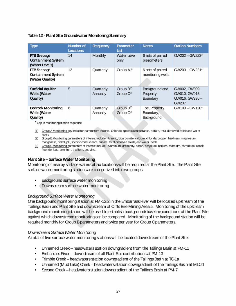
57
Table 12 - Plant Site Groundwater Monitoring Summary
Type Number of Locations
Frequency Parameter List
Notes Station Numbers
FTB Seepage Containment System (Water Levels)
14 Monthly Water Level only
6 sets of paired piezometers
GW202 – GW223*
FTB Seepage Containment System (Water Quality)
12 Quarterly Group A(1) 6 sets of paired monitoring wells
GW200 – GW221*
Surficial Aquifer Wells (Water Quality)
5 Quarterly Annually
Group B(2)
Group C(3) Background and Property Boundary
GW002, GW009, GW010, GW015, GW016, GW236 – GW237
Bedrock Monitoring Wells (Water Quality)
8 Quarterly Annually
Group B(2)
Group C(3) Toe, Property Boundary, Background
GW109 – GW120*
*Gap in monitoring station sequence (1) Group A Monitoring key indicator parameters include. Chloride, specific conductance, sulfate, total dissolved solids and water
levels. (2) Group B Monitoring parameters of interest include: Arsenic, bicarbonate, calcium, chloride, copper, hardness, magnesium,
manganese, nickel, pH, specific conductance, sulfate, total dissolved solids, and water levels. (3) Group C Monitoring parameters of interest include: Aluminum, antimony, boron, beryllium, barium, cadmium, chromium, cobalt,
fluoride, lead, selenium, thallium, and zinc.
Plant Site – Surface Water Monitoring Monitoring of nearby surface waters at six locations will be required at the Plant Site. The Plant Site surface water monitoring stations are categorized into two groups:
· Background surface water monitoring · Downstream surface water monitoring
Background Surface Water Monitoring One background monitoring station at PM-12.2 in the Embarrass River will be located upstream of the Tailings Basin and Plant Site and downstream of Cliffs Erie Mining Area 5. Monitoring of the upstream background monitoring station will be used to establish background/baseline conditions at the Plant Site against which downstream monitoring can be compared. Monitoring of the background station will be required monthly for Group B parameters and twice per year for Group C parameters. Downstream Surface Water Monitoring A total of five surface water monitoring stations will be located downstream of the Plant Site:
· Unnamed Creek – headwaters station downgradient from the Tailings Basin at PM-11 · Embarrass River – downstream of all Plant Site contributions at PM-13 · Trimble Creek – headwaters station downgradient of the Tailings Basin at TC-1a · Unnamed (Mud Lake) Creek – headwaters station downgradient of the Tailings Basin at MLC-1 · Second Creek – headwaters station downgradient of the Tailings Basin at PM-7

58
Monitoring of the downstream monitoring stations will be used to establish baseline conditions at the Plant Site prior to mining operations and to monitor potential project impacts once mining operations begin. Monitoring of the downstream monitoring stations will be required monthly for Group B parameters and twice per year for Group C parameters.
59
Additional Monitoring Chronic Whole Effluent Toxicity Testing As described in the Reasonable Potential section above, the MPCA has conducted a Reasonable Potential analysis and has determined there is no reasonable potential for NorthMet’s proposed discharges to cause or contribute to a violation of water quality standards in the receiving waters. The Project is considered a “major” facility by EPA. All major facilities are required to conduct either chronic or acute toxicity testing on the effluent from their wastewater treatment systems. Monitoring for whole effluent toxicity looks at the entire mixture of wastewater to determine whether the effluent is toxic. The draft permit requires PolyMet to monitor for Chronic Whole Effluent Toxicity (WET) for the life of the permit. The MPCA policy is to require Chronic WET testing when this ratio is less than or equal to 20:1. The draft permit contains chronic WET testing because the ratio of the receiving water 7Q10 flow to the facility’s proposed monthly average flow is zero. The draft permit requires chronic toxicity testing quarterly for the first year of the permit and annually after the first year. Quarterly monitoring was chosen for the first year of discharge due to the potential for variability in the effluent during the WWTS startup period. Annual monitoring is sufficient after the first year of operation due to the projected stability of the WWTS effluent. Because no Reasonable Potential has been found, a monitoring threshold value of 1.0 chronic toxic units (TUc) has been established. The results of the chronic toxicity tests will be evaluated against the monitoring threshold value of 1.0 TUc and the draft permit requires additional testing for any tests that exceed 1.0 TUc. The threshold value is not a WET Limit, but rather an “intervention limit” that requires additional testing if it is exceeded. The chronic toxicity tests must be conducted in accordance with procedures outlined in EPA-821-R-02-013 "Short-term Methods for Measuring the Chronic Toxicity of Effluents and Receiving Waters to Freshwater Organisms" - Fourth Edition (Chronic Manual) and any revisions to the Manual. Results collected during the permit cycle will be evaluated during permit reissuance to determine whether a permit limit for chronic whole effluent toxicity is necessary. Nutrients Nitrogen Nitrogen is a pollutant that can negatively impact the quality of Minnesota’s water resources, including water used for drinking. Studies have shown that excess nitrogen in lakes and streams has a toxic effect on aquatic life such as fish. Like phosphorus, nitrogen is a nutrient that promotes algae and aquatic plant growth often resulting in decreased water clarity and oxygen levels. In September 2014, the MPCA completed the final draft of the Statewide Nutrient Reduction Strategy (http://www.pca.state.mn.us/zihy1146 ) which identifies goals and milestones for nitrogen reductions for both point and nonpoint nitrogen sources within Minnesota. To gain a better understanding of the current nitrogen concentrations and loadings received by and discharged from the facility, effluent nitrogen monitoring has been added to the Permit. The draft permit includes effluent monitoring for Nitrite plus Nitrate-Nitrogen, Total Kjeldahl Nitrogen and Total Nitrogen at a frequency of twice per year for the five-year term of the permit. There is no nitrogen limit in the permit.

60
This additional monitoring will provide the data necessary to develop a better understanding of the total nitrogen concentrations and loadings that is currently being received and discharged from municipal and industrial wastewater treatment plants. Once a more extensive total nitrogen data set is established nitrogen reduction work can begin to achieve the necessary reductions to meet the goal of a 20% reduction in total nitrogen loads from point source dischargers by 2025. The changes and/or increases in total nitrogen monitoring in wastewater permits as a result of the Statewide Nutrient Reduction Strategy is outlined in the Minnesota NPDES Wastewater Permit Nitrogen Monitoring Implementation Plan document located on the MPCA wastewater permits webpage at: http://www.pca.state.mn.us/index.php/water/water-types-and-programs/wastewater/wastewater-permits/index.html. Phosphorus Phosphorus is a common constituent in many wastewater discharges and a pollutant that has the potential to negatively impact the quality of Minnesota’s lakes, wetlands, rivers, and streams. Phosphorus promotes algae and aquatic plant growth often resulting in decreased water clarity and oxygen levels. In addition to creating general aesthetic problems, these conditions can also impact a water body’s ability to support healthy fish and other aquatic species. Therefore, phosphorus discharges are being carefully evaluated throughout the state. Phosphorus is required to be monitored in the discharge twice per year in the draft permit to verify the expected low concentrations of nutrients in the discharge.

61
Special Permit Requirements 40 CFR 440 – Allowable Discharge Effluent Guidelines are national regulatory standards for wastewater discharged to surface waters and municipal sewage treatment plants. EPA issues these regulations for industrial categories, based on the performance of treatment and control technologies. In addition to the numerical technology based effluent limits identified in the Technology Based Effluent Limitations section above, 40 CFR § 440.104(b)(1) states, in part, “there shall be no discharge of process wastewater to navigable waters from mills that use the froth-flotation process alone, or in conjunction with other processes, for the beneficiation of copper, lead, zinc, gold, silver, or molybdenum ores or any combination of these ores.” Process wastewater is defined in 40 CFR § 122.2 as any water which, during manufacturing or processing, comes into direct contact with or results from the production or use of any raw material, intermediate product, finished product, byproduct, or waste product. The Project will produce process wastewater that is subject to this requirement. The federal effluent limit guidelines at 40 CFR part 440 identify two kinds of water that are not subject to the limitation on discharge of process wastewater: combined waste streams and net precipitation. 40 CFR § 440.131(a) discusses combined waste streams and states:
In the event that waste streams from various subparts or segments of subparts in part 440 are combined for treatment and discharge, the quantity and concentration of each pollutant or pollutant property in the combined discharge that is subject to effluent limitations shall not exceed the quantity and concentration of each pollutant or pollutant property that could have been discharged had each waste stream been treated separately. In addition, the discharge flow from the combined discharge shall not exceed the volume that could have been discharged had each waste stream been treated separately.
Mine drainage is the only waste stream combined with process wastewater that the Permittee proposes to count toward the “allowable discharge” that would not be prohibited by 40 CFR § 440(b)(1). Mine drainage, defined in 40 CFR § 440.132(h) as “any water drained, pumped, or siphoned from a mine” is excluded from the definition of “process wastewater” as used in this part. At the Project, mine drainage will be combined with process wastewater in the FTB Pond. Mine drainage will include all water pumped from the Mine Site to the Plant Site (includes water pumped directly to the FTB Pond and water pumped to the WWTS for treatment). No mine drainage will be directly discharged to the receiving waters, rather the discharge will consist of treated water from the WWTS.

62
The draft permit proposes the following formula to determine the “allowable discharge” that would not be prohibited by 40 CFR § 440(b)(1): Da = Y + Dm Where: Da = Allowable discharge Y = Annual net precipitation Dm = Mine drainage In addition, 40 CFR § 440.104(b)(2)(i) states:
In the event that annual precipitation falling on the treatment facility and the drainage area contributing surface runoff to the treatment facility exceeds the annual evaporation, a volume of water equal to the difference between annual precipitation falling on the treatment facility and the drainage area contributing surface runoff to the treatment facility and annual evaporation may be discharged subject to the limits set forth in [§440.104(a) (Table 2)] of this section.
The draft permit proposes the following formula to allow for this provision in the event precipitation exceeds annual evaporation at the site:
Y = (Af x P) - (At x E) where: Y = annual net precipitation Af = area of Tailings Basin (FTB + Cell 2W) plus the drainage area contributing surface runoff to the Tailings Basin and to the FTB seepage capture systems P = total annual precipitation At = open water area of the Tailings Basin E = annual reservoir evaporation The total allowable annual discharge under the draft permit is limited to the volume of net precipitation calculated using the above formula, plus the volume of mine drainage discussed above. Under the draft permit, if the Permittee does not discharge the allowable annual discharge volume in a given calendar year, then the Permittee may carry over the difference between the allowable annual discharge volume and the actual volume discharged as a credit to the allowable annual discharge volume for the following calendar year. Such credit may be carried over only to that calendar year immediately following the year in which not all of the allowable annual discharge volume was utilized. This provision recognizes and takes into account the fact that it is probable that precipitation falling in one year may not actually be discharged until the following year; travel and/or residence time within the wastewater management system may exceed one year. The approach is consistent with the intent of the regulation because the volume discharged will always remain below the cumulative net precipitation plus mine drainage. This is also consistent with MPCA’s past implementation of this requirement at other mining facilities.

63
No Unauthorized Discharge to Surface Waters Mine Site The only allowable discharges from the Mine Site are those authorized by Minnesota’s Industrial Stormwater General Permit and Construction Stormwater General Permit. The draft permit explicitly prohibits any discharge of wastewater to surface waters from the Mine Site. All mine-related wastewaters will be collected in various sumps and collection systems, routed to equalization ponds at the Mine Site, and then pumped via pipeline to the Plant Site for treatment and discharge at that location. Each of the Mine Site features will be constructed and managed such that there is no point source discharge to surface waters nor a discernable impact to surface waters or groundwater. The draft permit requires monitoring of the performance of the Mine Site engineering controls and the groundwater quality downgradient of the Mine Site features. This monitoring will ensure protection of groundwater in accordance with the requirements of Minnesota Rules chapter 7060 as well as ensure there is no impact to surface waters from the Mine Site. Mine Site features with the potential to affect groundwater are the Category 1, 2/3 and 4 Stockpiles, Ore Surge Pile , Overburden Storage & Laydown Area, and the Wastewater Equalization Ponds (Table 13). These features and their associated engineering controls to minimize affects to groundwater are further described below. Table 13 - Overview of Mine Site Infrastructure with Potential Nonpoint Discharge to Groundwater (SDS)
Project Feature Source of Potential Groundwater Flow
FEIS/Permit Application Assumed Flow Rate to Groundwater (gpm)
Category 2/3 Waste Rock Stockpile (Temporary)
Liner Leakage 0.019(1)
Ore Surge Pile (Temporary) Liner Leakage 0.0012(1)
Wastewater Treatment Equalization Basins
Liner Leakage 0.014(1)
Overburden Storage and Laydown Area
Infiltration 14(1)
Category 1 Waste Rock Stockpile Flow bypassing Category 1 Stockpile Groundwater Containment System
6.8(2)
(1) Information from Table 5.2.2-27 of the FEIS (2) Mine Year 11 (maximum) flow to bedrock that bypasses the containment system and does not discharge to the West Pit.
Information from Section 5.2.2 (p.5-145) of the FEIS
The monitoring required in the draft permit will identify the potential for impacts to surface water far enough in advance to allow implementation of adaptive management or mitigation actions that would prevent the impacts from occurring. Permanent Category 1 Waste Rock Stockpile Potential groundwater impacts from the Category 1 Waste Rock Stockpile (the only permanent waste rock stockpile at the Mine Site) will be controlled by installation of a groundwater containment system near the toe of the stockpile consisting of a low-permeability compacted soil hydraulic barrier (cutoff wall) coupled with a drainage collection system.

64
Drainage collected by the groundwater containment system will be routed to a number of lined sumps adjacent to the toe of the stockpile and from there pumped via piping to the lined wastewater equalization basins at the Mine Site. From there, the stockpile drainage, in combination with other Mine Site wastewater flows, will be pumped to the Plant Site for treatment at the WWTS. The containment system as designed will lower the water table on the inward side of the cutoff wall relative to the level that is maintained on the outward side. This will establish an inward hydraulic gradient thereby eliminating the potential for stockpile drainage to enter the surficial groundwater system. Any leakage through the low-permeability cutoff wall will be inward and will end up as part of the wastewater collected for treatment. Engineering controls:
· Installation of a groundwater containment system consisting of a cutoff wall (low-permeability compacted soil hydraulic barrier) combined with a drainage collection system around the perimeter of the stockpile near the stockpile toe. The groundwater containment system will be part of the initial construction prior to the stockpiling of waste rock and will be incrementally expanded as the stockpile is developed.
· Installation of a geomembrane cover system during the life of the Project to reduce pollutant load by reducing infiltration of precipitation. The cover system will be constructed incrementally as the stockpile is constructed during the period of mine operation and once completed will be maintained during closure and post closure.
· Mine pit dewatering will draw and collect groundwater and pump it to the WWTS for treatment. (The containment system and mine pits are expected to capture virtually the entire amount of stockpile drainage generated.)
Monitoring of the performance of the groundwater containment system will be conducted by the following:
· 7 sets of paired piezometers (14 total) along the length of the groundwater containment system, with one piezometer of each pair on the inward side of the cutoff wall and one on the outward side. The water level (i.e., groundwater elevation) will be monitored monthly at each piezometers to ensure that an inward-directed hydraulic gradient is maintained.
· 6 sets of paired monitoring wells (12 total) along the length of the groundwater containment system, with one well of each pair on the inward side of the cutoff wall and one on the outward side. The water level at each well will be monitored monthly to ensure that an inward-directed hydraulic gradient is maintained, with water quality for indicator pollutants being monitored quarterly.
· 3 monitoring wells in the surficial aquifer downgradient of the Category 1 stockpile will be monitored quarterly for water quality.
Temporary Waste Rock (Category 2/3 and Category 4) Stockpiles & Ore Surge Pile Category 2/3 waste rock, Category 4 waste rock and ore material that is stored temporarily at the Ore Surge Pile prior to transport to the processing plant at the Plant Site will be placed in separate temporary stockpiles at the Mine Site. Each of these stockpiles will have engineered geomembrane-based liner systems that will collect any water that has contacted the rock. The engineered liner system will consist of an overliner drainage layer, an impermeable composite liner barrier, and, if necessary, a foundation underdrain system located below the impermeable composite

65
barrier. The impermeable composite liner barrier, comprised of a compacted soil liner overlain by a geomembrane layer will prevent stockpile drainage from infiltrating downward. The overliner drainage layer will minimize the development of hydraulic head on the impermeable liner, which will minimize the potential for groundwater impacts due to any liner defects. The liners’ integrity will be protected by the foundation underdrain systems in areas where high groundwater is encountered to minimize potential for excess pore pressures adversely affecting the performance of the liner system as the stockpile is loaded. These three liner design components (underdrains, impermeable barrier, and overliner drainage layer) function as a system to enhance overall liner integrity and stockpile stability. Stockpile drainage will be collected above the liner in the high permeability overliner drainage layer, routed to lined sumps located at the toe of the stockpile, and then pumped to the Mine Site equalization ponds prior to pumping to the WWTS at the Plant Site for treatment. The temporary nature of these stockpiles will also limit their potential impacts to groundwater. The Category 2/3 Waste Rock Stockpile, the Category 4 Waste Rock Stockpile, and the Ore Surge Pile will have expected operating lives of 11 to 21 years. At the end of their operating lives, PolyMet will remove these temporary waste rock stockpiles and reclaim their footprints. Because these stockpiles are temporary, rather than permanent, there is less potential for degradation of the liners over time, and limited duration of potential groundwater effects from these features. Groundwater surrounding the temporary stockpiles will be monitored using five monitoring wells screened in the surficial aquifer. These wells (GW491-GW495) will be monitored quarterly for a focused set of key parameters and annually for a wider set of parameters. Overburden Storage & Laydown Area (OSLA) PolyMet will use the OSLA to screen, sort, and temporarily store peat and unsaturated overburden for future use at the Mine Site. Potential groundwater impacts from the OSLA will be controlled by facilitating the collection of runoff and drainage from the site to limit infiltration. Although the OSLA will not have an engineered liner system, the OSLA will be graded and compacted to enhance drainage. Drainage will be collected in an unlined mine water pond, then pumped to the FTB at the Plant Site. The OSLA runoff is expected to be of sufficient water quality so as not to require treatment beyond settling to remove suspended solids prior to pumping to the FTB. Any mercury that may be released from the stored peat will be removed with the settled solids in the collection pond and/or via filtration and adsorption by tailings particles at the FTB. Groundwater downgradient of the OSLA will be monitored using one monitoring well screened in the surficial aquifer. This well (GW411) will be monitored quarterly for a focused set of key parameters and annually for a wider set of parameters. Wastewater Treatment Equalization Basins Potential groundwater impacts from the equalization basins at the Mine Site will be controlled by installation of a geomembrane liner over a one-foot thick soil liner. Model calculations based on typical liner characteristics, expected hydraulic head, and measured hydraulic conductivity of system components indicate that leakage from the basins will be minimal and will not adversely affect Mine Site groundwater.
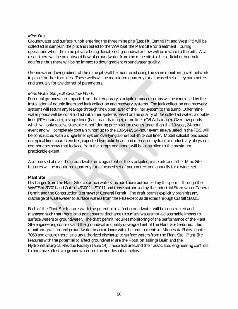
66
Mine Pits Groundwater and surface runoff entering the three mine pits (East Pit, Central Pit and West Pit) will be collected in sumps in the pits and routed to the WWTS at the Plant Site for treatment. During operations when the mine pits are being dewatered, groundwater flow will be inward to the pits. As a result there will be no outward flow of groundwater from the mine pits to the surficial or bedrock aquifers; thus there will be no impact to downgradient groundwater quality. Groundwater downgradient of the mine pits will be monitored using the same monitoring well network in place for the stockpiles. These wells will be monitored quarterly for a focused set of key parameters and annually for a wider set of parameters. Mine Water Sumps & Overflow Ponds Potential groundwater impacts from the temporary stockpile drainage sumps will be controlled by the installation of double liners and leak collection and recovery systems. The leak collection and recovery systems will return any leakage through the upper layer of the liner system to the sump. Other mine water ponds will be constructed with liner systems based on the quality of the collected water: a double liner (RTH drainage), a single liner (haul road drainage), or no liner (OSLA drainage). Overflow ponds, which will only receive stockpile runoff during precipitation events larger than the 10-year, 24-hour event and will completely contain runoff up to the 100-year, 24-hour event as evaluated in the FEIS, will be constructed with a single-liner system overlying a one-foot-thick soil liner. Model calculations based on typical liner characteristics, expected hydraulic head, and measured hydraulic conductivity of system components show that leakage from the sumps and ponds will be controlled to the maximum practicable extent. As discussed above, the groundwater downgradient of the stockpiles, mine pits and other Mine Site features will be monitored quarterly for a focused set of parameters and annually for a wider set. Plant Site Discharges from the Plant Site to surface waters include those authorized by this permit through the WWTS at SD001 and Outfalls SD002 – SD011 and those authorized by the Industrial Stormwater General Permit and the Construction Stormwater General Permit. The draft permit explicitly prohibits any discharge of wastewater to surface waters from the FTB except as directed through Outfall SD001. Each of the Plant Site features with the potential to affect groundwater will be constructed and managed such that there is no point source discharge to surface waters nor a discernable impact to surface waters or groundwater. The draft permit requires monitoring of the performance of the Plant Site engineering controls and the groundwater quality downgradient of the Plant Site features. This monitoring will protect groundwater in accordance with the requirements of Minnesota Rules chapter 7060 and ensure there is no unauthorized discharge to surface waters from the Plant Site. Plant Site features with the potential to affect groundwater are the Flotation Tailings Basin and the Hydrometallurgical Residue Facility (Table 14). These features and their associated engineering controls to minimize affects to groundwater are further described below.

67
Table 14 - Overview of Plant Site Infrastructure with Potential Nonpoint Discharge to Groundwater (SDS)
Project Feature Source of Potential Groundwater Flow
FEIS/Permit Application Assumed Flow Rate to
Groundwater (gpm) Tailings Basin Flow bypassing FTB seepage
capture system 20(1)
Hydrometallurgical Residue Facility (HRF)
Flow bypassing HRF Leakage Collection System
0(2)
(1) Information from Table 5.3.3-37 of the FEIS (2) Any minimal leachate bypassing the HRF Seepage Capture System would be captured by the FTB Seepage Capture
System prior to release to the environment Plant Site – FTB Seepage Capture Systems The FTB Seepage Containment System and the FTB South Seepage Management System (collectively known as the FTB seepage capture systems) will collect water seeping from the Tailings Basin as surface seepage or seepage to groundwater. The FTB Seepage Containment System will surround the western and northern sides and extend to a portion of the eastern side of the Tailings Basin. It will consist of a cutoff wall installed to the top of the bedrock, with a collection trench and drain pipe installed on the upgradient side (Tailings Basin side) of the cutoff wall. The collected seepage will then be pumped to the WWTS for treatment prior to discharge. The FTB South Seepage Management System, which will be an enhancement of the existing SD026 pumpback system, consists of a berm, trench, and pumpback system and collects seepage on the southern side of the FTB. The seepage collected by this system will also be pumped to the WWTS for treatment and discharge or to the FTB Pond for reuse. PolyMet will construct the FTB seepage capture systems to capture tailings basin seepage including both surface seepage emanating to the surface from the toe of the basin and seepage entering the surficial aquifer through the bottom of the basin. The systems will capture both nonferrous seepage from the Project Tailings Basin as well as existing legacy ferrous seepage from the basin. Over time, these engineering controls are expected to attenuate existing groundwater impacts outside of the FTB seepage capture systems that are attributable to the former taconite operations. Monitoring of the performance of the FTB Seepage Containment System will be conducted by the following:
· 6 sets of paired piezometers (12 total) along the length of the FTB Seepage Containment System, with one piezometer of each pair on the inward side of the cutoff wall and one on the outward side. The water level (i.e., groundwater elevation) will be monitored monthly at each piezometers to ensure an inward-directed hydraulic gradient is maintained.
· 6 sets of paired monitoring wells (12 total) along the length of the FTB Seepage Containment System , with one well of each pair on the inward side of the cutoff wall and one on the outward side. The water level at each well will be monitored monthly to ensure that an inward-directed hydraulic gradient is maintained, with water quality for indicator pollutants being monitored quarterly.
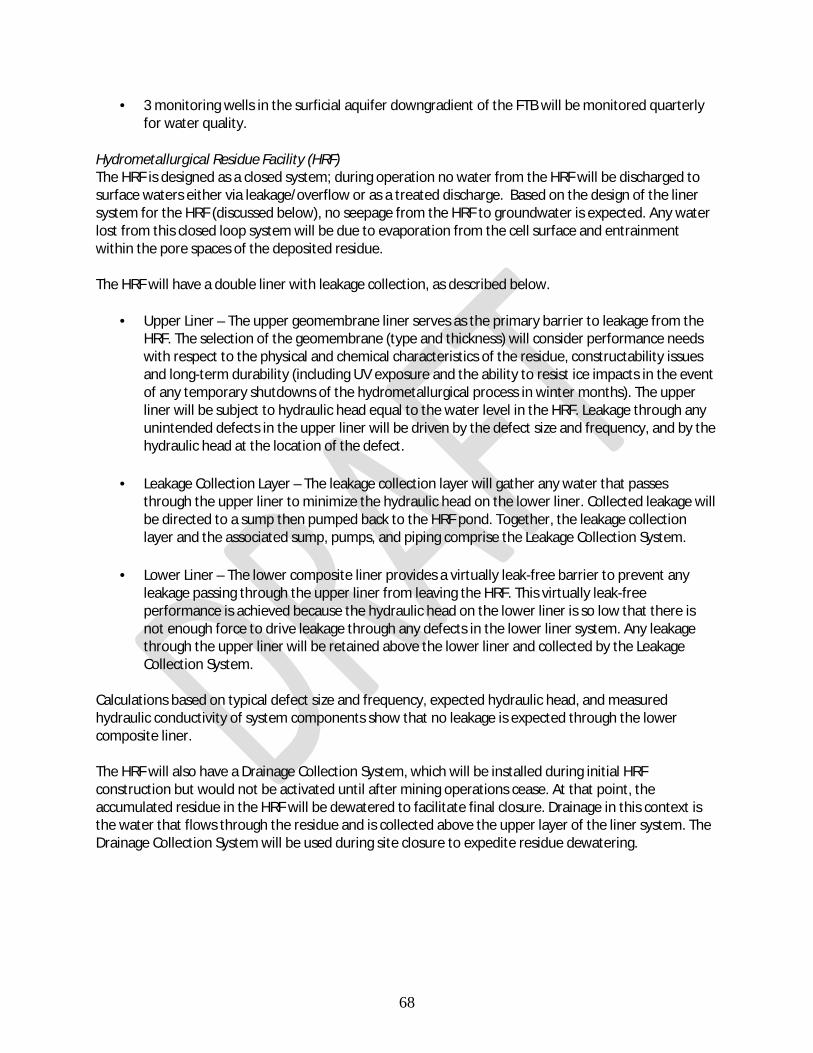
68
· 3 monitoring wells in the surficial aquifer downgradient of the FTB will be monitored quarterly for water quality.
Hydrometallurgical Residue Facility (HRF) The HRF is designed as a closed system; during operation no water from the HRF will be discharged to surface waters either via leakage/overflow or as a treated discharge. Based on the design of the liner system for the HRF (discussed below), no seepage from the HRF to groundwater is expected. Any water lost from this closed loop system will be due to evaporation from the cell surface and entrainment within the pore spaces of the deposited residue. The HRF will have a double liner with leakage collection, as described below.
· Upper Liner – The upper geomembrane liner serves as the primary barrier to leakage from the HRF. The selection of the geomembrane (type and thickness) will consider performance needs with respect to the physical and chemical characteristics of the residue, constructability issues and long-term durability (including UV exposure and the ability to resist ice impacts in the event of any temporary shutdowns of the hydrometallurgical process in winter months). The upper liner will be subject to hydraulic head equal to the water level in the HRF. Leakage through any unintended defects in the upper liner will be driven by the defect size and frequency, and by the hydraulic head at the location of the defect.
· Leakage Collection Layer – The leakage collection layer will gather any water that passes through the upper liner to minimize the hydraulic head on the lower liner. Collected leakage will be directed to a sump then pumped back to the HRF pond. Together, the leakage collection layer and the associated sump, pumps, and piping comprise the Leakage Collection System.
· Lower Liner – The lower composite liner provides a virtually leak-free barrier to prevent any leakage passing through the upper liner from leaving the HRF. This virtually leak-free performance is achieved because the hydraulic head on the lower liner is so low that there is not enough force to drive leakage through any defects in the lower liner system. Any leakage through the upper liner will be retained above the lower liner and collected by the Leakage Collection System.
Calculations based on typical defect size and frequency, expected hydraulic head, and measured hydraulic conductivity of system components show that no leakage is expected through the lower composite liner. The HRF will also have a Drainage Collection System, which will be installed during initial HRF construction but would not be activated until after mining operations cease. At that point, the accumulated residue in the HRF will be dewatered to facilitate final closure. Drainage in this context is the water that flows through the residue and is collected above the upper layer of the liner system. The Drainage Collection System will be used during site closure to expedite residue dewatering.

69
Special Permit Requirements – No Unauthorized Discharge Permit conditions to ensure there are no unauthorized discharges from the Mine Site and Plant Site:
· Permit conditions specifically prohibiting discharge to surface waters from the Mine Site and from the FTB Seepage Containment System and the HRF Leachate Collection Systems at the Plant Site.
· Requirement for all water collected by the groundwater containment systems at the Category 1 Waste Rock Stockpile and the FTB seepage capture systems to be routed to the WWTS or pumped to the FTB.
· Requirement to monitor and maintain a series of paired piezometers and wells at the Category 1 Waste Rock Stockpile and the FTB Seepage Containment System.
· Requirement for the facility to maintain an inward gradient at Category 1 Waste Rock Stockpile and the FTB Seepage Containment System and mitigation requirements to begin in the event inward gradients are not maintained.
· Requirement to conduct regularly scheduled inspections of the FTB Seepage Containment System and HRF Leachate Collection System
Annual assessment to ensure no unauthorized discharges from the Mine Site and Plant Site: The draft permit contains special requirements for both an Annual Groundwater Evaluation Report and an Annual Comprehensive Performance Evaluation Report in addition to the permit conditions mentioned above. The purpose of these reports is, in part, to utilize all available monitoring and operating data (including groundwater quality, groundwater elevation, waste stream monitoring and pumping records) to fully evaluate facility performance on an annual basis and to assess whether there is, or is the potential for, a discharge to surface waters. The annual evaluations will provide a comprehensive assessment of the facility engineering controls at the Mine Site and Plant Site in minimizing impacts to water resources downstream of the facility and will require an assessment of potential mitigation options or adaptive management is needed if the potential for an unauthorized discharge to surface waters exists. The Annual Groundwater Evaluation Report and the Annual Comprehensive Performance Evaluation Report are further discussed in the sub-section of the same name below.

70
Management of Water During Construction of FTB Seepage Containment System FTB Seepage Containment System Construction Seepage from the former LTVSMC tailings basin currently flows to the north and west from the basin as surface seepage or groundwater (deep) seepage. Cliffs Erie currently collects surface seepage, but does not collect groundwater seepage. As part of the Project, all of this seepage will be managed by the FTB Seepage Containment System. The FTB Seepage Containment System will collect seepage along the northern, northwestern, western, and a small portion of the eastern toes of the Tailings Basin dams and route it to the WWTS for treatment and subsequent discharge or to the FTB pond for reuse. Along most of the eastern side of the Tailings Basin, high bedrock will preclude seepage from leaving the basin in that direction, so additional containment is not warranted in those areas. The FTB Seepage Containment System will continue to collect the surface seepage from the basin that is currently being captured by Cliffs Erie, in addition to the seepage from the Tailings Basin that enters the surficial aquifer, runoff from the exteriors of the Tailings Basin dams, and runoff from the small watershed area between the toes of the dams and the containment system. The FTB Seepage Containment System will consist of a berm and access road through which a cutoff wall (a low permeability hydraulic barrier) will be placed from the surface through the existing surficial deposits to bedrock. A drainage collection system will be installed on the upgradient side, as shown in Figure 11. The drainage collection system will have a collection trench filled with granular drainage material and a perforated drainpipe located near the bottom of the trench. Vertical risers extending above ground surface from the drainpipe will collect runoff and surface seepage occurring upgradient of the FTB Seepage Containment System. Figure 11 - Conceptual Cross Section: FTB Seepage Containment System (from NorthMet Project Water Management Plan – Plant, Oct. 2017)

71
The access road will be located approximately 300 to 500 feet from the FTB. During construction, temporary culverts and/or gaps between segments of the containment system under construction will be placed as needed to allow for surface and groundwater to remain hydraulically connected from inside the system to the outside. The number of culverts and/or gaps and their actual locations will be determined in final design. The cutoff wall will not allow seepage to pass through the barrier and will force the runoff and groundwater seepage to be collected in the drainage collection system. Water collected by the FTB Seepage Containment System will be routed to the FTB Pond and/or the WWTS. (See Figures 1-4 below). Stormwater directly associated with construction of the containment system will be managed as construction stormwater and will be subject to the requirements of the General Construction Stormwater Permit (including development of a SWPPP and application of relevant Best Management Practices). These BMPs will include erosion and sediment control measures, and construction site restoration practices. During construction of the containment system, surface and groundwater will continue to flow through the gaps/temporary culverts in the road to maintain hydrologic connections in downgradient streams and wetlands during construction. These temporary culverts will be sealed or removed towards the end of the containment system construction and prior to placement of NorthMet tailings in the FTB, with any resulting accumulation of water behind the system routed to the FTB and/or the WWTS. The draft permit does not allow PolyMet to deposit nonferrous tailings in the FTB until the FTB Seepage Containment System along the northern and western sides of the Tailings Basin is fully functional. The segment along the eastern side of the Tailings Basin will be constructed concurrently with the east dam, prior to the time that FTB Cells 2E and 1E will merge (currently anticipated to be in approximately Mine Year 7). No seepage is expected along the eastern side of the Tailings Basin prior to the merging of FTB Cells 2E and 1E. The draft permit does not allow PolyMet to merge Cells 2E and 1E until the portion of the FTB Seepage Containment System on the eastern side of the Tailings Basin is fully functional. A network of monitoring wells and piezometers will be installed along the FTB Seepage Containment System to verify the performance of the system. The construction schedule for the FTB Seepage Containment System and associated monitoring system will be based on the time of year the NPDES/SDS permit is issued, as well as receipt of all other necessary permits for this work to commence. Two construction seasons will be necessary to install the FTB Seepage Containment System and associated monitoring wells and to conduct verification testing of its performance. Rationale for managing construction of the FTB Seepage Containment System under the Construction Stormwater General Permit General permits are authorized under 40 C.F.R. § 122.28 and Minn. R. 7001.0210. MPCA has determined that a general permit is appropriate to regulate discharges associated with construction activity because all construction activity involves substantially similar processes that disturb and expose topsoil and that result in discharges of sediment and potentially other pollutants associated with construction. MPCA is specifically authorized to issue a general permit to any category of point source stormwater discharges by Minn. Stat. § 115.03, subd. 5c (2016). The primary pollutant that is treated and controlled under the General Construction Stormwater Permit is sediment. Other pollutants associated with construction activities include nutrients, metals,

72
inorganics, pesticides, herbicides, construction chemicals, and petroleum products; note that these are pollutants from general construction activities, not specifically to the Project, and the Project may not include all of these pollutants. The construction of the FTB Containment System is not expected to encounter or release pollutants not already considered under the General Construction Stormwater Permit. The quantities of pollutants/pollution potential associated with construction activity vary and are dependent on the type of construction activity conducted at the site, the amount of land disturbance, topography, and the specific operating conditions at the site. Fluctuating rainfall and snow levels will also significantly affect discharge quantities. General permit coverage for construction activities at the Project, including for the FTB Seepage Containment System, addresses these differences by requiring the Permittee to develop and implement a project-specific Stormwater Pollution Prevention Plan (SWPPP) prior to conducting construction activity. The SWPPP allows the Permittee to choose the appropriate Best Management Practices or BMPs to address the potential discharge of sediment and other potential pollutants from the construction site, and to control the indirect pollution and degradation of surface waters resulting from the uncontrolled discharge of volumes of stormwater from impervious surfaces. Special Permit Conditions for Management of Water during Construction of the Seepage Collection System:
· PolyMet is prohibited from depositing nonferrous tailings in the FTB until the FTB Seepage
Containment System along the northern, northwestern, and western sides of the Tailings Basin is fully operating.
· PolyMet shall not merge Cells 2E and 1E until the portion of the FTB Seepage Containment
System on the eastern side of the Tailings Basin is fully operating.
· PolyMet shall obtain coverage under the Minnesota General Construction Stormwater permit for construction of the FTB Seepage Containment System. Water encountered during construction of the FTB Seepage Containment System shall be managed as construction stormwater. BMPs for sediment, erosion, and/or dust control are required to be implemented during construction of the FTB Seepage Containment System in accordance with the provisions of the General Construction Stormwater permit.
· PolyMet shall notify the MPCA within 30 days of completion of construction of the FTB Seepage Containment System.
· The Permittee shall notify the MPCA within 30 days of initiation of operation of the FTB Seepage Containment System and the introduction of nonferrous tailings to the FTB.

73
Attenuation of Legacy Tailings Basin Pollutants Background Water quality in the wetlands and other waters downgradient of the existing tailings basin, which LTVSMC operated until 2001, has been affected by ferrous (legacy) surface seepage and groundwater seepage. Baseline monitoring in Mud Lake Creek, Trimble Creek, and Unnamed Creek has documented exceedances of surface water quality standards for several parameters associated with the former ferrous operations, namely total dissolved solids (TDS), specific conductance, alkalinity and hardness. The MPCA and Cliffs Erie (CE) entered into a Consent Decree in 2010 to address alleged violations of permit conditions at the former LTVSMC site. Surface seepage collection began in 2011 when CE installed pumpback systems at various locations under the terms of the Consent Decree. The pumpback systems collect surface seepage that emerges near the toe of the tailings basin at former outfalls SD004 and SD006 on the west side of the tailings basin, and at Outfall SD026 on the south side. CE then pumps the collected seepage back to the tailings basin pond. Prior to the installation of the pumpback systems, the surface seepage flowed into the headwaters of Unnamed Creek and Second Creek. The pumpback systems are effective at capturing and removing surface seepage, but they are not designed to capture the seepage from the existing tailings basin to the surficial groundwater aquifer and are not intended to be permanent. Seepage along the northern, northwestern, and western toes of the existing tailings basin dams eventually upwells/flows to the wetlands adjacent to the basin and that are the headwater sources for Mud Lake, Trimble and Unnamed Creeks. To prevent both surface seepage and seepage to the surficial groundwater aquifer, both that are occurring currently due to legacy conditions and that could be created by the Project, from impacting downstream waters, PolyMet proposes to construct seepage capture systems around the FTB. The FTB Seepage Containment System will consist of a cutoff wall (a low-hydraulic conductivity barrier) extending through the existing surficial deposits to bedrock, with a drainage collection system installed on the upgradient side. Vertical risers extending above ground surface will collect runoff and surface seepage discharging upgradient of the cutoff wall. The water captured by the containment system will be routed to the FTB or the WWTS for treatment prior to discharge. When the Project begins operating, the existing legacy seepage and future nonferrous seepage captured by the seepage containment system will no longer contribute to the hydrology of the downstream wetlands and creeks. To obtain the benefits of the seepage capture system while at the same time maintaining the functional hydrology of these downstream waters, the collected seepage will be replaced with treated water from the Waste Water Treatment System (WWTS). The treated water, which will meet all surface water quality standards, will be discharged in a dispersed manner to the headwater wetlands immediately downstream of the capture system in the Trimble and Unnamed Creek watersheds. The existing seepage collection system installed by CE under the Consent Decree along a portion of the southern side of the existing tailings basin will be upgraded as part of the Project as necessary. PolyMet’s South Seepage Management System will function similarly to the containment system along the northern and western sides. The seepage (primarily consisting of surface seepage at this location) will be collected, routed to the WWTS for treatment with seepage from the FTB Seepage Containment

74
System, and then discharged to Second Creek as augmentation water just downstream of the capture system. Permitted Action In the time period after issuance of a permit to PolyMet and before the FTB Seepage Containment System is operational, the existing pumpback systems will continue to be operated in accordance with the Consent Decree between MPCA and CE. MPCA anticipates that CE’s obligations under the Consent Decree with respect to the existing tailings basin will be assigned to PolyMet or an affiliate. This will ensure that the obligations concerning operation of the pumpback systems remain in effect before the FTB Seepage Containment System is constructed and the WWTS begins operating. Once PolyMet begins operating the FTB Seepage Containment System and starts collecting the existing ferrous tailings basin seepage for treatment at the WWTS with subsequent discharge of treated augmentation water downgradient of the containment system, there will be a beneficial effect on downstream water quality. However, because there will be previously impacted waters attributable to pre-Project conditions remaining in waters downgradient of the containment system (both wetland water at the surface and deeper seepage that has yet to up-well into surface waters), there will be a period of time following the startup of FTB Seepage Containment System and WWTS before the pollutants in downstream waters are fully attenuated. In other words, there will be a lag in time before PolyMet’s capture of seepage and discharge of treated water will completely disperse the remaining legacy contaminants presently in downstream waters. The length of this lag time (which can also be referred to as the residence time) for remaining legacy pollutants was evaluated as part of the Project permitting process. The evaluation estimated how long it would take for the remaining legacy pollutants to be fully attenuated at the first (upstream most) surface water monitoring location in each of the three headwater tributaries north and west of the basin under various flow conditions (average flow, low-flow, and high flow conditions). The evaluation indicated that for a flow-through scenario (where the existing wetland water is essentially displaced by the treated water), it would take between 1 and 2 months under high flow conditions and 3-15 months under low flow conditions, depending on watershed, for the downstream water to be fully attenuated. A summary of the results is in Table 15. Table 15 - Estimated residence time for water in wetlands within the three watersheds
Hydrologic Scenario Monitoring Location, Subwatershed Flow-through Residence Time Estimate (months)
Average Conditions PM-11, Unnamed Creek 3.5 TC-1a, Trimble Creek 2 MLC-1, Unnamed (Mud Lake) Creek 2.5 Low-Flow Conditions (2) PM-11, Unnamed Creek 10 TC-1a, Trimble Creek 3 MLC-1, Unnamed (Mud Lake) Creek 15 High-Flow Conditions (3) PM-11, Unnamed Creek 2 TC-1a, Trimble Creek 1.5 MLC-1, Unnamed (Mud Lake) Creek 1
(3) Based on a goal of displacing 90% of the legacy water (4) Based on the 10th percentile modeled flow rate thorough the watershed from the FEIS modeling of the Plant Site (5) Based on the 90th percentile modeled flow rate through the watershed from the FEIS modeling of the Plant Site

75
A similar evaluation of residence time was not conducted for the South Seepage Management System and Second Creek because there is not expected to be a significant period of time between when this seepage capture system begins operation and when legacy pollutants in downstream Second Creek are fully attenuated. Unlike the seepage capture systems along the northern and western sides of the tailings basin, the South Seepage Management System will capture almost exclusively surface seepage with a relatively small percentage of the total flow consisting of captured seepage to groundwater. With the much higher flow velocities of surface seepage relative to deep seepage and the limited wetland area downstream of where the treated water would be discharged, attenuation is expected occur quickly and there should be little discernible lag time. Monitoring of the surface waters downstream of the existing tailings basin is currently being utilized to inform the actions taken under the MPCA-Cliffs Erie Consent Decree. This monitoring will continue during the Project construction and attenuation phases. The portion of the Consent Decree applicable to the former LTVSMC tailings basin, which will be assigned to PolyMet or an affiliate, deals with the legacy impacts from the previous ferrous operation. The Consent Decree will remain the regulatory vehicle for resolving these legacy ferrous impacts near the basin. The draft permit includes downstream surface water monitoring requirements for each of the tributaries receiving the discharge from the WWTS beginning once the Project seepage capture systems and WWTS become operational (after approximately 1-2 years of construction) and the legacy contaminants have been attenuated. Based on the evaluation of residence time above, the draft permit for the Project specifies that the surface water monitoring requirements will commence 18 months after the first discharge from the WWTS. A timeframe of 18 months was selected, rather than the 15 months indicated by the residence time evaluation above, to provide an allowance for the time of year that the WWTS actually begins operating; a discharge commencing in winter will likely exhibit a longer attenuation time than one commencing in summer due to typically lower flow rates in winter. Until that time, surface water monitoring at each of the locations will continue as described above such that the monitoring record will be continuous and will provide the water quality data necessary for determining when the attenuation of legacy contaminants is complete. The draft permit requires monitoring of downstream surface waters for the current key parameters of concern (sulfate, bicarbonate, specific conductance, total dissolved solids and copper) once per month with less frequent monitoring (quarterly/semi-annual/annual monitoring) for a wider range of parameters. A summary of the proposed downstream monitoring locations is in Table 16. Table 16 - Proposed Plant Site Downstream Surface Water Monitoring
Station Purpose SW003 (PM-11) Unnamed Creek downstream of stream augmentation and FTB Seepage Containment
System SW005 (PM-13) Embarrass River downstream of Tailings Basin to assess changes from background
conditions at SW008 after the performance of the FTB Seepage Containment System and stream augmentation
SW006 (TC-1a) Trimble Creek downstream of stream augmentation and FTB Seepage Containment System
SW007 (MLC-1) Unnamed (Mud Lake) Creek downstream of swale and FTB Seepage Containment System SW020 (PM-7) Second Creek downstream of stream augmentation and FTB South Seepage Management
System

76
Stormwater The discharge and management of construction stormwater and industrial stormwater for the Project will be regulated under the National Pollutant Discharge Elimination System (NPDES)/State Disposal System (SDS) Construction Stormwater General Permit (MNR100001) and the NPDES/SDS Industrial Stormwater General Permit (MNR050000) respectively. Because PolyMet will be required to obtain coverage under these general permits, this draft individual permit for the Project does not include provisions regulating the direct discharge of stormwater to surface waters. Construction Stormwater - Construction Prior to Operations The NPDES/SDS Construction Stormwater General Permit (CSW General Permit) authorizes the discharge of stormwater runoff from construction sites. This permit was reissued on August 1, 2013, and will expire on August 1, 2018. MPCA anticipates that the CSW General Permit will be renewed when it expires. Coverage under the CSW General Permit is required for construction activity that results in land disturbance of equal to or greater than one acre or a common plan of development or sale that disturbs an area greater than one acre. Coverage under the CSW General Permit is not required for stormwater from construction activities that is routed directly to and treated by a treatment works, as defined in Minn. Stat. § 115.01, subd. 21, that is operated under an individual NPDES/SDS permit with a Total Suspended Solids effluent limit for the treated runoff. CSW General Permit coverage will be required for the Project for stormwater generated from NorthMet construction prior to initiation of mining operations and operation of the WWTS. PolyMet has proposed to obtain separate CSW General Permit coverage for separate portions of the Project area. Separate coverage will be obtained for:
· Mine Site · Plant Site (Processing Areas) · Tailings Basin · Transportation and Utility Corridors
These areas will have separate Stormwater Pollution Prevention Plans (SWPPPs) under their respective CSW General Permit coverages. Construction Stormwater – Construction During Operations PolyMet has proposed to continue construction activities at the Mine Site and Plant Site for a number of years. Areas such as the stockpile or foundation construction as well as Tailings Basin dam lifts will likely continue to take place after the facility initiates operation. Stormwater discharges from ongoing construction activities, that are not otherwise collected for eventual treatment at the WWTS, will be regulated under the CSW General Permits. Separate CSW General Permit coverage is not required in the following situation:
· stormwater from construction activities is routed to an existing control structure (i.e. WWTS), · the existing control structure is regulated by the individual NPDES/SDS permit and · that individual permit includes a TSS limit for the discharge from the control structure.

77
This draft NPDES/SDS permit requires PolyMet to apply for and obtain separate coverage under the CSW General Permit for any new or additional construction activities generating stormwater not regulated under this draft NPDES/SDS permit. New SWPPPs will be required for any new CSW General Permit coverages. As construction of the site is completed or as construction areas are revegetated/stabilized, stormwater runoff from these former construction areas will either be permitted as industrial stormwater covered under the Minnesota ISW General Permit or will be treated as non-contact stormwater (which does not require permit coverage). Termination of the CSW General Permits for the Mine Site, Plant Site, and Tailings Basin areas will not be authorized until PolyMet has initiated operation of the WWTS. Termination will not be authorized for the Transportation and Utility Corridors until the completion of construction of the infrastructure associated with the railroad, Dunka Road, and the pipeline. These trigger conditions that must be met by PolyMet to request termination of CSW General Permit coverage for a construction activity have been included in this draft NPDES/SDS permit. Industrial Stormwater The NPDES/SDS Industrial Stormwater Multi-Sector General Permit (ISW General Permit) regulates industrial stormwater discharges to surface waters. Discharges of industrial stormwater from facilities having specific Narrative Activities or Primary Standard Industrial Classification (SIC) codes must obtain permit coverage for their ISW activities. The Project falls under the following SIC codes under Sector G: Metal Mining (Ore Mining & Dressing):
· 1021: Active Metal Mining Facilities – Copper Ores · 1041: Active Metal Mining Facilities – Gold Ores · 1099: Miscellaneous Metal Ores, Not Elsewhere Classified
The company has requested separate ISW General Permit coverage for the Mine Site, the Plant Site (including the Tailings Basin), and the Transportation and Utility Corridors. The reasons for three separate ISW General Permit coverages rather than a single coverage include:
· The three areas are geographically separate and distinct (i.e., the Mine Site is 6-8 miles separated from the Plant Site)
· Each area discharges industrial stormwater to different receiving waters, and · The applicable stormwater sectors are not uniform across all three areas
Separate SWPPPs will be required for each of the three areas covered by the ISW General Permits. The ISW General Permit includes requirements for a number of industrial sectors, each addressing specific industrial activity categories. Sector G of the permit covers metal mining facilities that discharge stormwater contaminated by contact with, or that has come in contact with, any overburden, raw material, intermediate product, finished product, byproduct, or waste product located on the site of the operation. PolyMet will be required to follow the Sector G requirements in the ISW General Permit at the Mine Site and Plant Site, including those related to benchmark monitoring. Sector P of the ISW General Permit covers stormwater discharges associated with industrial activity from land transportation and warehousing facilities. PolyMet will be required to follow the Sector P requirements for the Transportation and Utility Corridors.
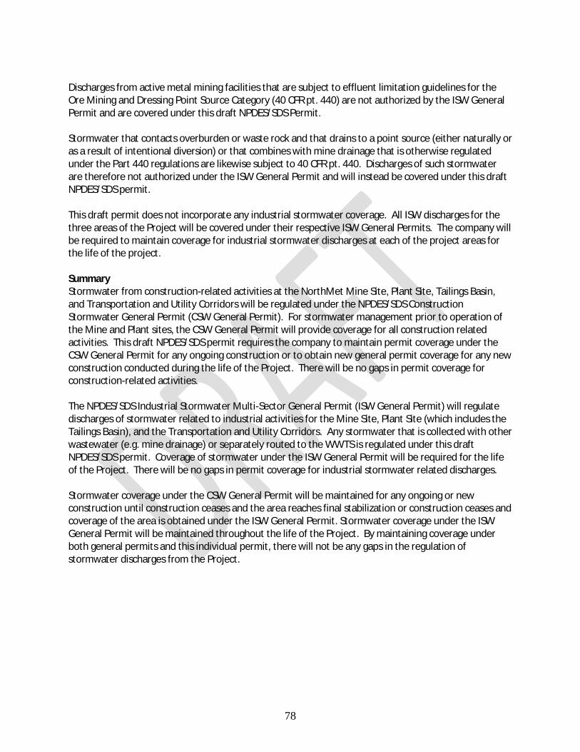
78
Discharges from active metal mining facilities that are subject to effluent limitation guidelines for the Ore Mining and Dressing Point Source Category (40 CFR pt. 440) are not authorized by the ISW General Permit and are covered under this draft NPDES/SDS Permit. Stormwater that contacts overburden or waste rock and that drains to a point source (either naturally or as a result of intentional diversion) or that combines with mine drainage that is otherwise regulated under the Part 440 regulations are likewise subject to 40 CFR pt. 440. Discharges of such stormwater are therefore not authorized under the ISW General Permit and will instead be covered under this draft NPDES/SDS permit. This draft permit does not incorporate any industrial stormwater coverage. All ISW discharges for the three areas of the Project will be covered under their respective ISW General Permits. The company will be required to maintain coverage for industrial stormwater discharges at each of the project areas for the life of the project. Summary Stormwater from construction-related activities at the NorthMet Mine Site, Plant Site, Tailings Basin, and Transportation and Utility Corridors will be regulated under the NPDES/SDS Construction Stormwater General Permit (CSW General Permit). For stormwater management prior to operation of the Mine and Plant sites, the CSW General Permit will provide coverage for all construction related activities. This draft NPDES/SDS permit requires the company to maintain permit coverage under the CSW General Permit for any ongoing construction or to obtain new general permit coverage for any new construction conducted during the life of the Project. There will be no gaps in permit coverage for construction-related activities. The NPDES/SDS Industrial Stormwater Multi-Sector General Permit (ISW General Permit) will regulate discharges of stormwater related to industrial activities for the Mine Site, Plant Site (which includes the Tailings Basin), and the Transportation and Utility Corridors. Any stormwater that is collected with other wastewater (e.g. mine drainage) or separately routed to the WWTS is regulated under this draft NPDES/SDS permit. Coverage of stormwater under the ISW General Permit will be required for the life of the Project. There will be no gaps in permit coverage for industrial stormwater related discharges. Stormwater coverage under the CSW General Permit will be maintained for any ongoing or new construction until construction ceases and the area reaches final stabilization or construction ceases and coverage of the area is obtained under the ISW General Permit. Stormwater coverage under the ISW General Permit will be maintained throughout the life of the Project. By maintaining coverage under both general permits and this individual permit, there will not be any gaps in the regulation of stormwater discharges from the Project.

79
Model Verification The draft permit contains special requirements that provide the means to periodically assess the performance of the probabilistic water quality models developed for the Mine and Plant Sites. This is accomplished by a comparing observed water quality and quantity values from permit-required monitoring against the values predicted by the modelling. The objectives of the model assessment requirements include:
· Direct comparison of observed data against GoldSim-predicted values · Confirmation that the model assumptions and construct are appropriate for continued use · Enabling ongoing use of the models by updating inputs to reflect current conditions · Use in conjunction with other tools to determine necessary management actions (i.e., adaptive
management, contingency actions and/or mitigation)
The model verification requirements include both a short-term assessment (annual assessment) and a longer-term assessment (5-year analysis). The draft permit requires the submittal of an Annual Model Verification Report that requires a comparison of observed monitoring data collected through the previous year to the values predicted by the GoldSim model as updated with actual inputs (e.g., climate, mine feature dimensions, material movement, waste rock sulfur content, inflow water quantity and quality, etc.). The assessment will focus on the key parameters of flows, sulfate, chloride, copper and nickel but can include other constituents as appropriate. The short-term analysis will include a ”backwards looking” component by evaluating whether observed flows and concentrations are within the range of predicted GoldSim values at critical comparison locations (e.g. mine pits, stockpile and seepage containment system sumps, collection ponds, and WWTS influents). It will also include a ”forward looking” component by assessing whether the updated predicted future concentrations are within the range of those predicted by GoldSim in previous long-term impact assessments. If any of the observed values are outside of the ranges predicted by GoldSim, the draft permit requires PolyMet to further assess these values against a series of questions:
· Do the observed values indicate the potential for increased Project impacts? · Are there indications that the model assumptions were incorrect? · Are the observed values the result of mine plan changes that were not captured in the relevant
GoldSim predictions? · Are the observed values indicative of potential undesirable or unacceptable future outcomes?
If the answer is “yes” to any of the questions above, the draft permit requires that PolyMet submit a Work Plan for MPCA approval that proposes actions or responses that will be taken to address any areas of concern identified during the model assessment process. The first Annual Model Verification Report is required to be submitted within 18 months of initiation of operation of the wastewater treatment system and annually after the first report is submitted. The draft permit also requires submittal of a Five Year Model Evaluation Report. This longer-term assessment is required to be submitted 180 days prior to permit expiration and be included with the application for permit reissuance. The Five Year Model Evaluation Report will have a broader focus and must include a comprehensive evaluation of the underlying conceptual models (e.g., XPSWMM, ModFlow, Geochemistry) and other supporting mathematical models that are used as inputs to the

80
GoldSim models as updated. The long-term assessment will also require an evaluation of the potential need for adaptive management, contingency actions, and/or mitigation options. Three years after permit issuance (1 ½ years before submittal of the Five Year Model Evaluation Report), the draft permit requires PolyMet to submit for MPCA approval a Work Plan describing in detail how the Five Year comprehensive evaluation will be conducted and the measures or performance standards against which conclusions on the performance of the GoldSim modeling will be made. The Work Plan must also identify the process for assessing whether the modeling evaluations warrant the need for adaptive management measures, contingency actions and/or other mitigations.

81
Annual Groundwater Evaluation Report and Annual Comprehensive Performance Monitoring Evaluation Report The draft permit requires an Annual Groundwater Evaluation Report (Groundwater Report) to provide an annual evaluation of the groundwater monitoring well data from the Mine Site and Plant Site. The Annual Groundwater Evaluation Report requires the Permittee to provide:
· A discussion on the statistical methodologies used in the Report and the rationale for their selection.
· An evaluation of the overall suitability of the existing groundwater monitoring network at the Mine Site and Plant Site to adequately monitor groundwater flows from the Mine and Plant Sites including whether any changes to the monitoring network are needed. If the evaluation indicates that changes to the monitoring network are needed, the Permittee shall: § Submit with the Groundwater Report a plan, for MPCA review and approval, that
describes in detail the changes proposed, including monitoring locations, parameters to be monitored and/or monitoring frequencies.
§ Install any approved monitoring wells within 1-year of approval of MPCA (and any other agencies necessary for well installation).
§ Upon installation of approved monitoring wells, sample the wells for the parameters and at the frequencies identified in the MPCA approval.
§ Data collected from any additional wells installed must be included in the upcoming year’s annual report.
· An evaluation of compliance with groundwater standards at the property boundaries of the Mine Site and Plant Site.
· An assessment of spatial distribution of groundwater quality and the current and future potential for migration toward or discharge to surface waters from the Mine Site and Plant Site.
· The Permittee shall provide an assessment on the potential for a north flow path in the bedrock or surficial aquifer north of PolyMet’s property boundary (north of the Partridge River) at the Mine Site. The assessment must provide discussion on whether or not a potential for a north flow path exists and the logic for that determination. If the potential for a north flow path exists, PolyMet must include a plan and schedule for MPCA review and approval for adaptive management or mitigation to prevent this northward groundwater flow. The plan and schedule must include: § A detailed description of the specific actions to be taken and how they will prevent a
north flow path, § A discussion on the timing of implementation of the actions such that a north flow path
is prevented before it can occur, and § Whether any additional permitting or approvals are necessary prior to implementation. § If necessary, the plan and schedule for adaptive management or mitigation must be
implemented in accordance with the MPCA-approved schedule.
The annual evaluation of groundwater data and evaluation of the monitoring well network will use a statistical evaluation to identify any potential impacts to groundwater and any potential for a discharge to surface waters from the Mine Site and Plant Site. The annual groundwater evaluation will provide early identification of potential impacts such that adaptive management, corrective actions, or mitigation can be implemented, if needed.

82
An annual evaluation of engineering controls at the Mine Site and Plant Site is also required by the draft permit. PolyMet is required to submit an Annual Comprehensive Performance Report (Performance Report) which will provide an annual comprehensive assessment of the ability of the facility engineering controls at the Mine Site and Plant Site to prevent impacts to water resources downstream of the project. The Performance Report requires PolyMet to evaluate all relevant monitoring and performance data, including waste stream monitoring results, surface water monitoring results, and internal operational data. If the evaluation of the facility indicates the engineering controls are not operating as intended or are not providing a sufficient level of controls, the Performance Report must describe in detail the adaptive management or corrective actions that are being done, or will be done to correct the problem, including a schedule for their implementation. The goal of the engineering controls at the Mine Site and Plant Site is to prevent pollutants from various engineered project features from reaching the groundwater and surface waters. The annual evaluation of groundwater data, surface water data, waste stream data, and internal monitoring data will provide a frequent evaluation of the performance of the engineering controls and the monitoring networks at the Mine Site and Plant Site. An annual evaluation of the engineering controls along with the evaluation of relevant monitoring and performance data will provide early identification of potential impacts from the project and will help determine the need for adaptive management, corrective actions, or mitigation to prevent potential impacts to the groundwater and surface waters.

83
Hydrometallurgical Residue Facility Construction PolyMet has proposed to build a Hydrometallurgical Plant to further process the concentrate from the flotation process at the Plant Site. The hydrometallurgical process results in the generation of waste residue that is proposed to be disposed of in the Hydrometallurgical Residue Facility (HRF). The HRF will be constructed in an area adjacent to the Tailings Basin currently occupied by the former LTVSMC Emergency Basin. The Emergency Basin was originally located over a portion of a wetland containing deposits of peat of variable thickness and was originally designed to contain taconite tailings from the main LTVSMC tailings thickeners in the event of a power failure. Existing materials in the Emergency Basin, which will serve as foundation materials for portions of the HRF, include the localized peat deposits as well as hydraulically deposited fine tailings and slimes. These materials have experienced relatively little consolidation since LTVSMC operations ended in 2001. The HRF is designed to permanently store residue generated from the NorthMet hydrometallurgical process. The HRF is proposed to be constructed to a height of 80 feet with an approximately 300 acre footprint. It is designed to store approximately 6.5 million cubic yards of residue. The HRF will have a double liner system consisting of two barrier layers separated by a leakage collection layer. The upper geomembrane liner will serve as the primary barrier to leakage from the HRF. The lower composite liner will provide a virtually leak-free barrier to prevent any water that passes through the upper liner from leaving the HRF. The Leakage Collection System, to be located between the two liners, will collect any water that passes through the upper liner and pump it back to the HRF Pond. No discharge is allowed from the HRF. Soil borings conducted to date indicate that the subsurface materials within the Emergency Basin are relatively variable and complex. Variable subsurface conditions can potentially lead to foundation soil settlement and differential settlement, which could adversely affect the integrity and effectiveness of the HRF liner and seepage collection system. To mitigate the potential for differential settlement, PolyMet has proposed to place a preload over the affected area to pre-consolidate the sediments prior to liner placement. The preload will consist of incrementally placing layers of soil and/or rock fill above the existing foundation materials to compress them to specified levels to reduce the risk of excessive settlement and subsequent poor liner system performance during and post HRF construction. To address concerns about whether the proposed preload effectively addresses the degree of variability within the sediments, as well as to address uncertainties about the nature of the sediments in an area within the HRF footprint not subject to previous soil borings, the Permit requires PolyMet to submit a Preload Design Investigation Work Plan (PDIW) 12 months prior to implementation of the preload. The PDIW requires several plans to be developed and submitted for MPCA review and approval prior to construction of the HRF. PolyMet and MPCA will utilize this planning process to appropriately address the timing, sequencing, and overall schedule for the elements of the preload work. The PDIW includes the following sub-plans:
· Supplemental Subsurface Investigation Plan (SSIP): The purpose of the SSIP is to obtain additional information on subsurface soil conditions to better understand the in-situ soil conditions and refine the HRF preload design to minimize the uncertainty associated with differential settlement. The goal of the SSIP is to ensure that the types of information gathered and methods used to acquire that information will meet the needs of the HRF Preload Plan described in the draft permit. The SSIP Plan will ensure that the types of information gathered and methods used to acquire that information will meet the

84
needs of the HRF Preload Plan described below. The SSIP must propose investigation and testing methods and locations for additional investigation in the (previously/currently) inaccessible portion of the Emergency Basin where the HRF will be constructed.
· Working Platform Development Plan (WPDP):
The purpose of the WPDP is to identify and provide details on the proposed methods used to ensure a safe and stable working platform over the soft soils that are present within the Emergency Basin. It will also be used to minimize differential settlement and long-term HRF liner stress due to localized displacement.
Once the HRF site has been investigated and the subsurface conditions characterized, the Permit requires PolyMet to submit for approval a HRF Preload Design Plan (HPDP). The purpose of the HPDP is to incorporate the results of the SSIP and WDP to develop the Design and Specification documents for the preload. The HPDP requires the following information:
· Design and Specification Documents: The Design and Specification documents must:
§ identify locations where soft soil remediation measures, other than preload, will be used;
§ specify the total proposed consolidation stress that will be applied to foundation soils;
§ where different preload heights and stress levels will be applied, identify the extent of each area and stress level;
§ detail the preload extent and limits along the side slope of the existing tailings basin cell 2W;
§ identify the preload materials and placement methods including constraints on equipment;
§ the geotechnical instrumentation that will be used to determine when pore water pressure dissipation and consolidation settlement is functionally complete; and
§ provide an estimate of preload time required for each area within the HRF footprint.
· Geotechnical Instrumentation & Monitoring Plan (GIMP): A Geotechnical Instrumentation & Monitoring Plan (GIMP) is required to be developed and submitted with the HPDP but can be a separate document. The GIMP will be used to determine when excess pore pressures have dissipated within the various soft soil deposits used during the preload construction process. The GIMP is required to identify and provide details on the type, number, and locations of instrumentation used to determine when settlement is functionally complete after preload construction. Quarterly reporting of monitoring results to the MPCA is required by the draft permit.
· Wick Drain Plan (WDP): The Permittee may choose to propose the use of wick drains to accelerate consolidation settlement. If the Permittee proposes to use wick drains, a Wick Drain Plan (WDP) is required. The WDP requires PolyMet to incorporate results of consolidation tests performed on samples of fine tailing/slimes and peat collected as part of the SSIP and will also be used to develop the design and specification documents for the HRF Preload Design Plan described below.

85
· HRF Liner Plan (HLP): A HRF Liner Plan (HLP) discussing necessary design elements is required to be submitted with the HPDP but can be a separate document. The purpose of the HLP is to reduce the potential for liner deformation and distress during construction and operation of the HRF. The HLP must include, at a minimum, the following provisions required for the design:
§ If the primary liner is proposed to be exposed, it must be at least 100-mil high density polyethylene (HDPE); any alternative to this design requires MPCA approval;
§ the secondary liner must be at least 60-mil HDPE; any alternative to this design requires MPCA approval;
§ the design must incorporate a lysimeter under the HRF sump or other suitable monitoring devise located northwest of and proximal to the HRF and within the FTB Seepage Containment System to assess the facility’s impact on groundwater quality;
§ strain gauge(s) or other strain monitoring systems must be included with the liner to monitor and provide assurance that the liner system is not subject to excessive strain;
The MPCA will contract with a qualified third-party geotechnical consultant to provide expertise for the review of the geotechnical aspects of the Preload Design Investigation Work Plan, HRF Preload Design Plan, and associated sub-plans. The geotechnical consultant will review and provide comment, as needed, on the submitted plans, monitoring data, associated reports, and design of the HRF preload. MPCA review and approval of the PDIW and HPDP is required before preload construction activities can begin. Furthermore, removal of the preload and/or initiation of HRF construction (e.g., dam construction, liner installation) is not permitted until MPCA provides written approval to remove the preload; this is also expected to require review from the MPCA’s third party geotechnical consultant.

86
Total Facility Requirements The Total Facility Requirements chapter in the draft permit describes standard conditions that must be incorporated in all NPDES permits. Standard conditions specified in Title 40 of the Code of Federal Regulations (CFR) 122.41 and 122.42 are incorporated into the Total Facility Requirements chapter and identify standard conditions which include various legal, administrative, and procedural requirements of the permit. The standard conditions include definitions, prohibitions, liabilities, sampling and testing procedures, records retention, notification requirements, operation and maintenance requirements, penalties for noncompliance and other Permittee responsibilities. Summary of Plan, Report and Work Plan Submittals A summary of submittals required by the draft permit is provided in Table 17. Table 17 – Summary of Required Submittals
Submittal Due Sulfate Reduction Evaluation Plan 1 year after permit issuance Annual Model Verification Report 18 months after initiation of operation of the
WWTS; then annually by May 31 of each year following permit issuance
Five Year Model Evaluation Report Work Plan 3 years after permit issuance Five Year Model Evaluation Report 180 days before permit expiration Annual Groundwater Evaluation Report March 31 of each year following permit issuance Annual Comprehensive Performance Evaluation Report
April 30 of each year following permit issuance
HRF Preload Design Investigation Work Plan 12 months prior to placing fill material for preload construction
HRF Preload Design Plan 60 days prior to placing fill material for preload construction
Equalization Basin Performance Evaluation Report
180 days before permit expiration
Dike Seepage Survey Report January 31 of each year following permit issuance Application for Permit Reissuance 180 days before permit expiration
Mercury Minimization Plan A requirement to complete a Mercury Minimization Plan has not been included in the draft permit. Because the Project is already incorporating effective engineering controls for the capture of Project wastewater and is implementing advanced wastewater treatment that will result in the removal of mercury to concentrations less than the water quality standard for waters within the Lake Superior Basin, a plan to further minimize mercury is not required or warranted. The draft permit contains requirements for monitoring mercury from various wastewater sources at the Mine Site as well as the influent and effluent from the WWTS treatment trains. This monitoring will allow for an effective assessment of overall facility performance with respect to the control of mercury.

87
Cross-Media Analysis A cross-media analysis was conducted by PolyMet to address potential water quality concerns from dust deposition from the Project. This analysis included air modeling of potential facility-generated dust particles, an evaluation of the potential for release of sulfate and metals from oxidation of the deposited dust, and the resulting potential for impact on the quality of down-gradient waters, including wetlands. PolyMet submitted its Cross-Media Analysis to Assess Potential Effects on Water Quality from Project-Related Deposition of Sulfur and Metal Air Emissions on October 31, 2017, with supplemental information submitted November 29, 2017. The analysis was reviewed by MPCA’s technical experts. Based on its review of the cross-media analysis, the MPCA concluded:
1. The analysis developed a reasonable and protective scenario that showed no measurable changes of mercury in water or fish from Project-related air deposition of sulfur.
2. There will be no exceedances of copper, cobalt, and arsenic Class 2D water quality standards or to any other numeric water quality criteria from Project-related air emissions or the cumulative impact of Project-related air emissions.
3. The Project will not result in any measurable changes to water quality downstream of the Project in the St. Louis River, including downstream locations at Forbes (upper St. Louis River).
MPCA’s review of the cross-media analysis did not result in any additional requirements in the NPDES/SDS permit.
Antidegradation in Surface Waters Antidegradation standards and requirements are found in Minnesota Rules parts 7050.0250 to 7050.0335. Antidegradation standards for bioaccumulative chemicals of concern in the Lake Superior basin (Minnesota Rules 7052.0300 to 7052.0330) also apply. As required by these rules, PolyMet submitted an Antidegradation Evaluation as part of the NPDES/SDS permit application. The Antidegradation Evaluation and MPCA’s subsequent review demonstrate that water quality degradation caused by the proposed Project cannot be avoided, but will be prudently and feasibly minimized, existing and beneficial uses will be protected, and the proposed activity is necessary to accommodate important economic or social changes in the geographic area in which degradation of existing high water quality is expected. The proposed Project will implement the best technology in practice and treatment. Therefore, the MPCA has made a preliminary determination that the Project will satisfy antidegradation standards in Minnesota Rules 7050.0265, 7052.0300, and 7052.0330. MPCA’s review of the Antidegradation Evaluation is included as Attachment 3 to this Fact Sheet. Nondegradation in Groundwater Minnesota Rules part 7060.0500 identifies a Nondegradation Policy applicable to underground waters of the state. To address these requirements, PolyMet submitted a Nondegradation of Groundwater Evaluation as part of the July 2016 NPDES/SDS permit application with subsequent updates to the Evaluation included in the October 2017 updated application. MPCA’s review of the Groundwater Nondegradation Evaluation consisted of two components and was primarily based on information in the July 2016 permit application. The first component was an assessment whether the Project will satisfy the requirements of Minnesota Rule 7060 while the second

88
component was an attached detailed description and assessment of the site hydrogeology incorporating information from sources in addition to information in the application. Because MPCA’s review of the Groundwater Nondegradation Evaluation was completed prior to submittal of the October 2017 updated permit application, the review did not fully capture or acknowledge some of the specific updates that were included in the updated application. For example, MPCA’s hydrogeological review recommended installation of an additional monitoring well in a particular hydrogeologically-favorable area at the Mine Site with the result that this well location was included in the updated application and draft permit. MPCA also incorporated into the draft permit the hydrogeological review’s recommendation on the use of appropriate statistical methods in the review of groundwater monitoring data. The Nondegradation of Groundwater Evaluation and the MPCA’s subsequent review demonstrate that the requirements set forth under Minnesota Rules 7060 for protection of groundwater resources have been satisfied and that the proposed groundwater monitoring included in the NPDES/SDS permit will verify the protection of the groundwater resources. Therefore, the MPCA has made a preliminary determination that the project satisfies the nondegradation standards in Minnesota Rules 7060. Furthermore, the MPCA has determined that even though its review of the Groundwater Nondegradation Evaluation occurred prior to submittal of the October 2017 updated application, its conclusions and preliminary determination would not be different than had the updated information been available. MPCA’s review of the Nondegradation Evaluation is included as Attachment 4 to this Fact Sheet. Permit Expiration The draft permit extends for a period of five years, the maximum allowed. Attachments Attachment 1 - Summary of Monitoring Stations and Monitoring Requirements Attachment 2 – Chemical Additives Attachment 3 – Antidegradation in Surface Waters Attachment 4 – Nondegradation in Groundwater Attachment 5 – Acronyms and Abbreviations