National Institute of CAIIAC - gatech.edu
108
NIST AMTech CAIIAC Project Composite Joining and Repair Roadmap A Technology Roadmap for Joining and Repair of Advanced Polymer Matrix Composites CAIIAC Program Manager: Jean-Louis Staudenmann, National Institute of Standards and Technology Principal Investigators: Ben Wang, Georgia Institute of Technology Chuck Zhang, Georgia Institute of Technology Co-Investigators: Charles Browning, University of Dayton Leslie Kramer, Advanced Materials Professional Services, LLC Zhiyong (Richard) Liang, Florida State University Consortium for Accelerated Innovation and Insertion of Advanced Composites (CAIIAC) CAIIAC National Institute of Standards and Technology U.S. Department of Commerce
Transcript of National Institute of CAIIAC - gatech.edu

NIST AMTech CAIIAC ProjectComposite Joining and Repair Roadmap
A Technology Roadmap for Joining and Repair of Advanced Polymer Matrix Composites
CAIIAC
Program Manager: Jean-Louis Staudenmann, National Institute of Standards and TechnologyPrincipal Investigators: Ben Wang, Georgia Institute of Technology Chuck Zhang, Georgia Institute of TechnologyCo-Investigators: Charles Browning, University of Dayton Leslie Kramer, Advanced Materials Professional Services, LLC Zhiyong (Richard) Liang, Florida State University
Consortium for Accelerated Innovation and Insertion of Advanced Composites (CAIIAC)CAIIAC
National Institute ofStandards and TechnologyU.S. Department of Commerce


A Technology Roadmap for Joining and Repair of Advanced Polymer Matrix Composites
CAIIAC
Program Manager: Jean-Louis Staudenmann, National Institute of Standards and TechnologyPrincipal Investigators: Ben Wang, Georgia Institute of Technology Chuck Zhang, Georgia Institute of TechnologyCo-Investigators: Charles Browning, University of Dayton Leslie Kramer, Advanced Materials Professional Services, LLC Zhiyong (Richard) Liang, Florida State University
Copyright 2017 Georgia Tech Manufacturing Institute
Consortium for Accelerated Innovation and Insertion of Advanced Composites (CAIIAC)
National Institute ofStandards and TechnologyU.S. Department of Commerce


Table of ContentsAbout this Roadmap Page 2
Acknowledgements Page 3
Executive Summary Page 4
1. Introduction Page 5 1.1 CAIIAC Motivation and Goals Page 6 1.2 CAIIAC Team and Partners Page 8 1.3 Overview of Industry Needs for Composite Joining and Repair Page 9 1.3.1 Aerospace Page 9 1.3.2 Automotive Page 10 1.3.3 Wind Energy Page 11 1.3.4 Pressure Vessels and Pipes Page 12
2. Methodology Page 13 2.1 Data Collection Page 14 2.2 Meta-Roadmapping Page 14 2.3 XRL Metrics and Analysis Page 15
3. Roadmap Development Page 16 3.1 Non-Destructive Inspection Page 16 3.1.1 State-of-the-Art NDI Page 16 3.1.2 Challenges and Emerging Solutions for NDI of Composites Page 23 3.1.3 NDI Roadmap Summary/ NDI Roadmap Pages 26-27 3.2 Materials Page 28 3.2.1 State-of-the-Art of Materials Used in Composite Joining and Repair Page 28 3.2.2 Challenges and Emerging Solutions for Composite Repair Materials Page 31 3.2.3 Materials Roadmap Summary/ Materials Roadmap Pages 36-37 3.3 Processes Page 38 3.3.1 State-of-the-Art of Composite Joining Processes Page 38 3.3.2 State-of-the-Art of Composite Bonded Repair Processes Page 45 3.3.3 Challenges and Emerging Solutions for Joining and Repair Page 52 3.3.4 Processes Roadmap Summary/ Processes Roadmap Page 57 3.4 Computational Tools Page 58 3.4.1 State-of-the-Art of Computational Tools for Composite Joining and Repair Page 58 3.4.2 Challenges and Emerging Solutions for Computational Tools Page 59 3.4.3 Computational Tools Roadmap Summary/ Computational Tools Roadmap Page 64
3.5 Automation Page 64 3.5.1 State-of-the-Art of Composite Repair Process Automation Page 64 3.5.2 Challenges and Emerging Solutions for Repair Process Automation Page 65 3.5.3 Automation Roadmap Summary/ Automation Roadmap Page 68 3.6 Workforce Training, Standards, and Regulatory Issues Page 70 3.6.1 Current Industry Status of Composite Repair Training Page 70 3.6.2 Challenges and Emerging Solutions for Composite Repair Training Page 70 3.6.3 Current Industry Status of Standards Used for Composite Joining and Repair Page 72 3.6.4 Challenges and Emerging Solutions for Standards Development/ Implementation Page 76 3.6.5 Current Industry Status for Regulation of Composite Repairs Page 77 3.6.6 Challenges and Emerging Solutions for Regulation of Composite Repairs Page 77 3.6.7 Training, Standards, Supply Chain, and Regulatory Roadmap Summary Page 80
4. Conclusions and CAIIAC Future Outlook Page 81 4.1 Prioritized Demonstration Projects Page 82 4.2 Consortium Model and Future Plans Page 84
5. Appendices Page 85 5.1 Meta-Roadmapping Page 85 5.2 XRL Metrics and Analysis Page 89
XRL Appendix 1 – Technology Readiness Level Definitions Page 93
XRL Appendix 2 – Manufacturing Readiness Level Definitions Page 94 XRL Appendix 3 – Business Case Readiness Level Definitions Page 96 XRL Appendix 4 – Tool Maturity Level Definitions Page 97 5.3 Executive Committee Page 98 5.4 Industry Experts Panel Page 98 5.5 Contributors Page 99
References Page 101
1

The overall vision of the Consortium for Acceler-ated Innovation and Insertion of Advanced Com-posites (CAIIAC, pronounced “KAYAK”) is to create an innovative domestic manufacturing ecosystem to significantly shorten the manufacturing devel-opment cycle time, and provide right-the-first-time material yields for broad-based composite pro-cesses. Guided by this vision, the CAIIAC planning committee developed a three-fold mission to: 1) ac-celerate innovation, development and deployment of advanced composites; 2) develop broad-based applications for advanced composites; and 3) en-courage invent here, build here in the United States to improve U.S. competitiveness and capability to sell advanced composite products globally.
In preparing the CAIIAC Planning Grant proposal and progress reports during each performance peri-od, a team of organizers at Georgia Tech collected a large amount of data from representatives of nearly 60 organizations, including Advanced Materials Professional Services, Florida State University, the University of Dayton, and companies and government laboratories representing numerous industrial sectors including aerospace, automotive, energy. A majority of these partners are small- or medium-sized enterprises that play a critical role in the U.S. supplier network. The team identified and prioritized critical technical challenges includ-ing: 1) performing quick, reliable and verifiable repairs; 2) creating standards for composite design and testing to accelerate and lower costs for the certification process; 3) developing scalable and reproducible out-of-autoclave processes and af-fordable tooling; 4) implementing structural health monitoring of life cycle performance; 5) including nanomaterials for improved performance; and 6) recycling composites.
We ultimately decided to focus the roadmapping effort on Composite Joining and Repair (CJAR), since this market is highly underserved, but has
significant growth momentum and a promising return-on-investment (ROI). The worldwide main-tenance, repair, and overhaul market (MRO) is ex-pected to grow at a compound annual growth rate (CAGR) of 3.8% reaching about $65 billion by the year 2020. In contrast, the Airbus A350 and Boeing 787 composite aircraft MRO market is growing at a much faster rate, a CAGR of 17.9%, from $348 million to $1.81 billion by 2030. On average, the cost to repair a composite aircraft component is roughly one-third the cost of replacing the com-ponent. The speed of repairs is also important, as the average composite repair takes nearly 15 hours. Grounding an Airbus A350 for an entire day could cost in excess of $100 thousand in lost revenue for the airline company (≥ $4 thousand per hour). The ultimate goal of CAIIAC will be to reduce compos-ite repair cost and repair cycle time by at least 50% by 2030, i.e. the end of the CAIIAC roadmapping period. Previous and current roadmapping efforts sponsored by the National Institute of Standards and Technology (NIST) have addressed the oth-er five challenges. According to discussions held during the roadmapping process, industry experts feel that CJAR encompasses many aspects of the other challenges and should therefore, be the grand challenge.
Thus, the specific vision of CAIIAC is to bring CJAR technology into maturity within the next 15 years and thereby enable low cost, high performance, and rapid repair methods. This would be a direct result of our industry led consortium focus on the near-term, mid-term and long-term milestones out-lined in this technology roadmap. Effective CJAR for advanced composite structures will ultimately result in accelerated innovation and rapid insertion of advanced repair methods for advanced compos-ite products. To achieve this goal, CAIIAC proposes to focus on two strategic objectives: 1) Develop advanced materials, processes, and evaluation tech-niques for enhancing performance and reliability
About this Roadmap
2

NIST AMTech CAIIAC ProjectComposite Joining and Repair Roadmap
of composite repairs in various environments; and 2) Create or facilitate the developmental infrastruc-ture and a collaborative ecosystem to accelerate an industry-led approach to solve CJAR challenges. The roadmap acts as a guide toward achieving these objectives.
To our knowledge, this is the first roadmap docu-ment with a primary focus on future technological advancements in composite structural repair for a variety of major industries including aerospace, au-tomotive, pressure vessels/pipes, and wind energy. We believe the successful growth of these industries domestically is critical for the resurgence of manu-facturing and sustainment of economic recovery in the United States. Although a variety of composite materials and application areas were considered during this roadmapping effort, the focus is pri-marily on carbon fiber reinforced polymer (CFRP) composites for the aerospace industry given its established prevalence in this market and potential impact on the U.S. economy.
AcknowledgementsThis roadmap would not have been possible without the collective effort of numerous public and private organizations. The process was led by experts at the following organizations: Advanced Materials Professional Services; Florida State University, Tallahassee, Florida; Georgia Institute of Technology, Atlanta, Georgia; and the Univer-sity of Dayton, Ohio. Approximately 60 additional CAIIAC partners representing industry, academia, government agencies, standards organizations, professional societies, and trade associations gave substantially of their time and knowledge to ensure success of the project. CAIIAC organizers at Geor-gia Tech facilitated and organized the workshops, supported the overall roadmapping process, and prepared this report. All CAIIAC partners are iden-tified in Appendices 5.3 - 5.5 of this report. We also gratefully acknowledge the financial support from the NIST AMTech program (grant# 70NAN-B14H051) and guidance of Jean-Louis Stauden-mann, AMTech program manager.
Georgia Institute of Technology Professor Chuck Zhang, center, and Delta Air Lines TechOps engineers inspect damage to a composite structure at Delta Air Lines. (Source: Georgia Institute of Technology)
3

Executive Summary
In 2014, NIST AMTech provided funding to Georgia Tech to de-
velop a national technology roadmap and establish a consortium
organization to speed the domestic market insertion of advanced
composite products. This resulted in the formation of the Con-
sortium for Accelerated Innovation and Insertion of Advanced
Composites (CAIIAC). Georgia Tech worked with over 40 com-
panies, numerous government agencies, national labs, universi-
ties, and trade associations to identify industry critical challenges
and the proposed solutions outlined in this roadmap. After
analysis and input, the decision was made to focus on composite
joining and repair (CJAR). CAIIAC used an innovative me-
ta-roadmapping methodology to build this roadmap by combin-
ing qualitative data such as expert opinions, workshops, surveys,
and quantitative data extracted from patents and publications.
Here, we present the first ever technology roadmap on CJAR,
which provides a foundation for the first national, public-private
partnership for CJAR. The next phase of CAIIAC is to pursue
research, development and demonstration projects determined
as a result of this roadmapping exercise, with long-term goals of
developing a vibrant and sustainable domestic supplier network
to reduce composite repair cost and cycle time at least 50% by
2030.
4

NIST AMTech CAIIAC ProjectComposite Joining and Repair Roadmap
1. Introduction
Today, many transportation vehicles from small cars to mega ton airplanes are built using composites. As the use of compos-ites has accelerated, so does wear and tear on the vehicles built with them. A challenge exists in how to maintain and repair the composites without having to replace huge sections of the structures. Only by solving this challenge, can we ensure the safety and long-term reliability of aircraft and other critical structures made from composites at reasonable cost. CAIIAC decided to focus its roadmapping effort on Composite Joining and Repair (CJAR) because it is a highly underserved market that has significant growth momentum [1] and a promising return on investment (see Section 1.1). CAIIAC used an innovative meta-roadmapping process, combining qualitative data such as expert opinions collected via interviews, workshops, and surveys with quantitative data extracted from patents and publications (see Chapter 2 and Appendix 5.1), to develop the CJAR roadmap. CAIIAC organizers held four Industry Expert Workshops on Oc-tober 14, 2014; November 5, 2014; March 26, 2015; and March 29, 2016. Experts primarily represented airlines and original equipment manufacturers (OEMs) in the aerospace industry. In addition, a selected group of industry experts from the auto-motive and wind energy industries and material and tooling suppliers that support the targeted application fields for this roadmapping effort were present. At these workshops, over 30 experts shared their knowledge and experience on current indus-try practices regarding CJAR, the needs and gaps, and potential solutions for solving industry relevant CJAR challenges.
5

1.1 CAIIAC Motivation and Goals
The number of commercial aircraft manufactured with advanced composite materials is increasing at an unprecedented rate. For example, a majority of load-bearing structural components on the wide-body Boeing 787 and Airbus A350 are already made from composites, with future deliveries expected at a rate of 12-14 aircraft per month, up to 2,500 and 2,200, respectively, by 2030. Further, both Boeing and Airbus have significantly accelerated pro-duction/deliveries (up to 120 aircraft per month) of next generation single-aisle (i.e. narrowbody) airplanes which will continue to dominate the market (68% of commercial aircraft demand from 2009-2029) with increased adoption of composite structural components, in addition to new or retro-fitted internal cabins and galleys made from com-posite sandwich structures. Composites are used to gain energy efficiency, design flexibility, passenger comfort and durability. Furthermore, there is sig-
nificant interest and growing use of composites in other major industries including wind energy, auto-motive, marine, piping, and infrastructure. Perfor-mance improvements, design flexibility, reduced energy use, lower carbon emissions, and associated economic benefits have been important drivers for widespread industry adoption of composites.
Because the use of composites is increasing (Figure 1), there is a great need for an industry-wide tech-nology roadmap for CJAR and a coordinated R&D effort to address industry concerns (see Section 1.3) in the United States. The roadmapping effort presented herein on CJAR is extremely important to numerous industries, but particularly for the aerospace industry. Its significance goes beyond the obvious safety implications of having in service old-er aircraft made from aging composites. CJAR also greatly impacts the country’s ability to improve national security by having military equipment
Figure 1. Diagram showing the increasing industry and societal usage of advanced composites in recent years.
2011 2013 2014 2016 2017
Breakdown of materials used in the 787 and the A350. (Source Boeing and Airbus, respectively)
Airbus A350
2015 backlog for commercial composite (>50%) aircraft:
» 787: 850 units » A350: 750 units
The large number of legacy military aircraft requiring CJAR:
» UH-60: >4,000 since 1974 » C-130: >2,500 units since 1954
BMWi3 Electric CFRP Car (Source: BMW)
2016 and beyond: increased use of composites in the auto, energy and infrastructure fields.
Dodge Viper (Source: Fiat Chrysler Automobiles)
40,000 units/year
Wind Turbine (Source: Pixabay)
6

NIST AMTech CAIIAC ProjectComposite Joining and Repair Roadmap
Figure 2. Market forecast for maintenance, repair, and over-haul of Airbus A350 and Boeing 787 composite aircraft.
A350 & B787 MRO Market
A35
0 &
B78
7 M
RO
Mar
ket
(M$) 2000
1500
1000
500
0
$348 M
$1.81B
2020 2030
Year
CAGR = 17.9%
maintained and ready to deploy. There are also monetary benefits that include increased on-time airline departures/arrivals, reduced emissions and fuel consumption, and high market growth that may increase jobs. The worldwide maintenance, repair, and overhaul market (MRO) is expected to grow at a compound annual growth rate (CAGR) of 3.8% reaching about $65 billion by the year 2020. In contrast, the Airbus A350 and Boeing 787 compos-ite aircraft MRO market is growing at a much faster rate, a CAGR of 17.9%, from $348 M to $1.81 billion by 2030 (Figure 2). However, while the MRO market size is increasing worldwide the growth in Asia is double the world rate [2]. One reason is because Asia is currently taking the lead in the maintenance and repair market, and aircraft OEMs can save money by outsourcing the MRO component to Asia. Thus, it is imperative that the United States increase its global competitiveness by developing the infrastruc-ture, capabilities, equipment, and business ecosys-tem to provide efficient CJAR services domestically.
The financial impact of more efficient CJAR services on the aerospace industry alone would be tremen-dous. The composite airframe lifecycle MRO cost is estimated at 7.7% of the initial aircraft purchase cost. For example, if an Airbus A350 was purchased for $270M, then the MRO cost over the life of the aircraft is estimated at $20.8M. Likewise, if a Boe-ing 787 was purchased for $218M, then the MRO cost over the life of the aircraft is estimated to be $16.8M. The total airframe lifecycle MRO cost for all A350 and B787 aircraft delivered by Year 2021 is
estimated to be at ~$34 billion. The MRO costs can be significantly reduced by implementing on-air-craft repairs rather than part replacements.
The cost to repair a composite aircraft component averages about one-third the cost of replacing it. The speed of repairs is also important. Ground-ing an Airbus A350 for an entire day could cost in excess of $100k in lost revenue for the airline company (> $4k per hour). Considering that the average permanent composite repair, as permit-ted in Structural Repair Manuals (SRMs), takes roughly 15 hours, according to the ATA/IATA/SAE Commercial Aircraft Composite Repair Commit-tee (CACRC), in-situ composite repairs performed on the flight line can be costly while causing flight delays and cancellations [3]. It’s a dilemma made more challenging by fast gate turnarounds — be-tween 30 and 60 minutes for domestic flights — and an overwhelming lack of line mechanics with specialized training in repairing composite structures. Flight line environmental elements (rain/snow/humidity/wind/dust) are another major hurdle to expedited flight line repairs. While inflatable enclosures may be used in some cases for protection from the elements, this adds time and man-power to the repair.
The goal of CAIIAC is to reduce composite repair cost and repair cycle time by at least 50% by 2030, or the end of the CAIIAC roadmapping period. The consortium plans to reach this goal by pursuing R&D activities outlined in the technology road-map and transitioning the results and technolo-gy developments directly into industry practice. Further, the CAIIAC technology roadmap will be an evolving document that is updated annually by the CAIIAC consortium to address shifting indus-try needs. The outcome of the CAIIAC effort will ultimately enable improved reliability and confi-dence for CJAR resulting in an accelerated use of composite products. Moreover, CAIIAC will eventu-ally boost job creation by establishing a vibrant and sustainable supplier network for composite repairs throughout the United States.
7

1.2 CAIIAC Team and Partners
CAIIAC is composed of partnerships between industry, government, academia, and professional organizations that were formed over the two years of the NIST AMTech program performance period. Key partnerships were solidified between OEMs (e.g. Airbus, Boeing, Fiat Chrysler Automobiles, LMCO, Spirit AeroSystems, Lockheed Martin/ Sikorsky Aircraft, TPI Composites); users/operators (e.g. Delta Air Lines, U.S. Air Force); material sup-pliers (e.g. Cytec Solvay Group, Henkel); equipment vendors (e.g. BCT GmbH, Laser Technology, Inc.,
LSP Technologies); major R&D and test organi-zations (A*STAR, Fraunhofer Institute, NIAR); technical training providers (e.g. Abaris Training, MGSU); and standards/regulatory organizations (e.g. FAA, NIST, SAE, ACMA, CACRC). Interviews were conducted with experts from over 60 compa-nies and industry organizations, including a large number of small and medium-sized enterprises (SMEs) that support OEMs in a wide range of sec-tors. It was important to the success of the project to engage the full value chain. (Figure 3 provides more information on partnerships.)
Figure 3. Map showing major CAIIAC partners and potential consortium members.
»American Composites Manufacturers Association »American Chemistry Council »Air Force Office of Scientific
Research »Genesis Engineering
Solutions, Inc.
»Autodesk, Inc. »Chasm Technologies »Raytheon
»Lockheed Martin/ Sikorsky Aircraft »Swan Chemical, Inc. »United Technologies
Research Center »University of
Massachusetts Lowell
»SAE International (CACRC) »Laser Technology Inc. »TA Instruments, LLC
»Chomorat
»Oak Ridge National Laboratory
»Delta Air Lines, Inc. »FAA Atlanta ACO »Georgia Aerospace Systems
Manufacturing, Inc. »Georgia Automotive
Manufacturers Association »Georgia Manufacturing
Extension Partnership »Generation Orbit Launch
Services, Inc. »Georgia Center of
Innovation for Aerospace »Middle Georgia State University »SoftWear Automation, Inc. »Stratton Composite
Solutions, Inc. »ThyssenKrupp Elevator Corp.
»CMC, Inc. »Honeycomb Company
of America, Inc.
»Baker Hughes »Bell Helicopter Textron, Inc.
»Cytec Solvay Group
»Accelent Techologies, Inc. »Criterion Composites, Inc. »LMCO »San Diego Composites »Society for the Advancement of
Material and Process Engineering »Toray
»ATK »Spirit AeroSystems »WSU/NIAR
»Fiat Chrysler Automobiles »Altair
»Optomec
»Southwest Nanotechnologies, Inc.
»MEPOL
»MADE, LLC »Boeing
»Air Force Research Laboratory »GE »LSP Technologies, Inc. »Owen Corning
»NASA Langley Research Center
»A*STAR/SIMTech, Singapore »Airbus, France »BCT, Germany »Fraunhofer Institute,
Germany
International Partners
Collaboration with National and International Partners
»Abaris Training
8

NIST AMTech CAIIAC ProjectComposite Joining and Repair Roadmap
1.3 Overview of Industry Needs for Composite Joining and Repair
As already mentioned, the use of composites is increasing dramatically in the aerospace, automo-tive, wind power, pressure vessel and piping, and other commercial industries. With this increased use there is concern that repair performance (i.e. percentage of restoration of a damaged part’s mechanical properties relative to the original structure), speed, and costs may be inadequate. In addition, there are concerns about the long-term safety and reliability of current repair perfor-mance. The true lifespan of composite products subjected to daily real-world use is uncertain since the composites industry is still in its infancy. Further, industry-wide standards for repairs on major commercial (non-military) primary load-ed composite structures are scarce, and there is limited data on repair performance. Industry use of composites for principle structural elements in commercial applications is far less mature than for metallic structures. The aerospace and automotive industries have a long track record in developing, manufacturing and repairing metallic structures. Fatigue and corrosion are well-known degradation mechanisms in metals, whereas these processes are not generally a concern in carbon fiber-reinforced polymer composites (CFRPs). In contrast, impact damage is generally not a major safety concern in metals because of the inherent material ductility and energy absorbing mechanisms. However, com-posite structures are inherently brittle and can only absorb energy in elastic deformation and through damage mechanisms, making them sensitive to impact damage [4]. Further, composites are highly process sensitive, enabling greater design and pro-cessing flexibility compared to metals because their local properties can be tailored to meet the design specific requirements. The reliability of current repair techniques/procedures for composite parts is still being evaluated. Best practices are evolving through unexpected service findings, dissemination of general knowledge, etc., while the metallic repair procedures are well established. Simple transfer of
joining and repair techniques for metallic parts to composites is not a viable solution.
1.3.1 Aerospace
In the commercial aircraft industry, the Airbus A350 and the Boeing 787 are the two most recent airframes that are more than 50% composites by weight. China has also developed a new commercial aircraft, the C919, whose fuselage is made from composites. The safety-critical components in these designs represent the first robust application of composites for “light weighting” aircraft. Earlier versions of commercial aircraft also incorporated composite parts; however, many of these were non-structural like shrouds and access covers. Previous-ly, composites were used as secondary structures because they did not affect the flight safety of the vehicle, making their extended service time perfor-mance (i.e. durability) less critical. Now that the aerospace industry is moving to primary loaded composite structures, long-term degradation be-havior will be critical.
CJAR has long been practiced on military aircraft, as well as on secondary or non-flight-critical com-posite structures of commercial aircraft. Two kinds of damage are commonly found on these types of aircraft. First, composite skins are vulnerable to penetration or delamination. Secondly, sandwich structures, where a core is bonded between two skins, often have significant impact cratering and
Boeing 787. (Source: The Boeing Company)
9

debonding; or water retention damage such as plasticization, swelling, and hydrolysis [5]. Typical damage occurrences often differ between commer-cial and military aircraft. Damage incurred by com-mercial aircraft is most often caused by impacts, such as bird strikes, lightning strikes, in-flight hail, material handling, ground vehicle impacts (during loading/unloading of provisions or baggage), and foreign object damage [6]. Military aircraft face these impact concerns, as well as blast and frag-mentation damage from enemy projectiles. Both front and lower fuselage sections, leading edges, and lower wing skin components are commonly damaged by impact events. Composite sandwich structure is frequently used for engine nacelle panels. These structures are frequently damaged because they are frequently opened for service or in-spection and are generally close to the ground (i.e., close to service vehicle traffic).
Depending on the impact symmetry and velocity, local composite geometry and a myriad of other factors, local replacement of the material affected by an impact event is often required. Standardized repair of damaged composite skins using adhesive bonding techniques have been reviewed extensively in the literature [7, 8]. Customized milling ma-chines can be used to excavate sandwich structural damage, but major technical activities need to be implemented to address kissing bonds, automated repair tooling, composite surface cleanliness and treatment for bonding, non-destructive inspec-tion, and several other issues discussed in detail in Chapter 3.
1.3.2 Automotive
There is growing interest in composites from the automotive industry with several auto-OEMs, such as Ferrari, Lamborghini, BMW, Alpha Romeo, and Dodge (Viper) already selling commercial products with significant composite content. The primary motivation for using composites in the automotive industry is light-weighting, which helps OEMs abide by new emissions regulations and prepare to meet upcoming Corporate Average Fuel Economy (CAFE) requirements. Other reasons for the inter-est include the opportunity for parts consolidation to reduce the total number of parts and joining processes, design flexibility, corrosion resistance, material anisotropy, and enhanced mechanical properties. However, large scale use of composites in the automotive industry is impeded by high material and manufacturing costs, slow production rates, limited industry confidence and experience with these materials, and recyclability issues. Cost is a major driver in automotive production, which makes high throughput and the efficient use of automated production processes very important to manufacturers. Further, the crashworthiness requirements of automotive structures are quite different from those of the aerospace industry. In a crash, the car’s parts must fail in a controlled fash-ion so that the energy of the impact is absorbed by the structure itself rather than the occupants.
Repair of a composite automotive structure may be a simple activity if the damaged part can be replaced in-kind. However, if a composite auto-mobile has major structural damage, the ability to make these repairs is extremely limited and requires unique tooling not commonly found in today’s auto body shops. Furthermore, there is risk that underlying damage or weak/kissing bonds in the composite parts that affect structural strength may go undetected, although the surface of the vehicle appears cosmetically pristine. Doublers are not used in automotive repair like they are in repairing airplanes because aesthetic appearance is import-ant to customers. To satisfy customer demand and
Airbus 350. (Source: Airbus)
10

NIST AMTech CAIIAC ProjectComposite Joining and Repair Roadmap
meet safety requirements, these specific CJAR issues need to be addressed by automotive manufacturers before composite vehicles can become a widespread commercial reality. The challenge is to develop au-tomotive-specific technology for CJAR that is very easy to use with the ability for rapid, low-cost, and reliable repairs that promote post-accident custom-er safety.
BMW has released the i3 electric vehicle and the i8 high-performance sports vehicle, both of which contain a significant proportion of composite structures. However, many of the primary or critical structural components are still made out of alu-minum rather than composites. For example, the i8, which is more composite intensive than the i3, has a chassis that is all carbon composite; however, both the front and rear crash structures are metal (Al or steel). This creates a critical challenge of find-ing reliable multi-material or hybrid joining pro-cesses for automotive manufacturing and repair, and corrosion protection between carbon compos-ites and the metal. It is unlikely that there will be a vehicle made solely of composites. It is more likely that there will be a hybrid material approach. Nev-ertheless, there is an expectation that 10 years from now, the automotive and aerospace industries will be quite similar in terms of CFRP composites us-age. The current BMW i3 car is primarily comprised of thermoset materials because the use of thermo-plastics is less mature and the related supply chain is undeveloped. Pending further technological developments, additional thermoplastic parts may be incorporated into next generation composite
vehicles. Damage containment is notably superior in thermoplastics and some simpler technologies, such as ultrasonic welding, could be used for rapid repairs.
1.3.3 Wind Energy
More than 90% of conventional wind blades are made with glass fiber composite materials, primari-ly for cost reasons. As the wind power business ma-tures, wind turbines are being designed and built with larger blades. Currently, power outputs from these devices exceed 6 MW and require composite structures that are tens of meters in length (35–62 meters). Because production of these machines is so cost sensitive, most vendors still use a relatively low volume of carbon fiber in the blade structures. However, as bigger, longer wind blades are manu-factured, there is more interest in using stiffer and lighter carbon fiber composites despite the upfront higher cost.
If a large wind turbine blade suffers major fatigue damage or other structural degradation, the ma-chine owner or manufacturer often undergoes an economic analysis to determine whether to repair or replace the blade. The economic analysis exam-ines the cost of lost power generation, as well as repair costs, to determine whether a part replace-ment will take less time, incur less overall cost, and be more reliable than implementing a repair. The
BMWi3 CFRP electric car. (Source: BMW)
Wind turbine. (Source: Pixabay.com)
11

repair vs. replace decision is complicated by several factors, including the fact that it can take up to six months to acquire a crane for the replacement, adding the risk of substantial power generation downtime. With all considered, including both the shipment and labor of a blade replacement, it may or may not be more cost-effective than having the blade repaired. For the long term, however, it would seem that blade repair would be a better option for this industry. Low-cost, ambient environment, me-chanically reliable, and rapidly implemented com-posite repair technologies are critical to reducing outage time in wind turbines. Composite repairs on wind turbines are currently considered more of an art, rather than a science, and are neither performed by the wind farm operator or the blade OEM. Instead a contractor or third party with proprietary knowledge and experience will often perform the inspections and/or repairs onsite.
1.3.4 Pressure Vessels and Pipes
Composite materials are widely used in pressure vessels and pipes (PVPs). Composite pressure ves-sels such as type III and type IV gas tanks are the most commercialized methods to store and trans-port compressed hydrogen gas and compressed natural gas (CNG), which are used for automotive and energy transportation industries. Explosive containment vessels (ECVs) made of composite materials have been carefully developed and are used in the national defense or public safety fields. For example, filament-wound ECVs are capable of sustaining shock waves and other types of internal high explosions. In addition, filament or steel-wound composite pipes are increasingly used within the oil and gas transportation industry due to their excellent corrosion resistance and flexibility compared to traditional metallic pipes. Composite PVPs can take advantage of their multi-material components such that they are tailor-designed to meet severe application environments, with superi-or performance relative to a monometallic pressure vessel or pipe. However, the existence of multi-phase or multi-element materials also presents difficulties in their joining and repair.
CJAR of PVPs is a major concern for future appli-cation and promotion of composite PVPs. Primary challenges include non-destructive verification of joint structural integrity after bonding or welding. The time it takes to make repairs and the prob-lems created when fluid transmission is disrupted within PVP systems while the repair is being made also present challenges. Benefits of effective CJAR of PVPs include safer operations by eliminating potential cutting and welding related explosions, decreased external corrosion growth rate due to the inherent use of non-metallic materials, and shielding the environment from damage while the pipeline continues in service. Additionally, com-posite repairs are a cost effective option compared to the typical repairs of other PVPs such as sewer lines and metallic pipelines that are often corroded. The challenges faced by CJAR technology on PVPs include the implementation of non-destructive inspection (NDI) of bonded composites structures, the repair material and tooling, the structural performance testing, and fatigue life of bonded repairs.
Pipelines for oil and gas transportation. (Source: Cytec Solvay Group)
All-composite pres-sure vessels. (Source: Composite Technol-ogy Development, Inc.)
12

NIST AMTech CAIIAC ProjectComposite Joining and Repair Roadmap
The CAIIAC roadmapping effort consisted of three major steps: (1) data collection; (2) data analysis and roadmap development; and (3) data validation and extraction of consortium research, development and demonstration (RD&D) proj-ects. In step one, various data gathering methods were used including interviews of subject-matter experts, workshops and expert panel meetings, surveys, and data mining of publication and patent databases. Step two involved analysis of the data collected. Novel aspects of step two also included
meta-roadmapping and an XRL assessment (de-scribed in greater detail below), which were used to help quantify trends or assign ratings to the data collected. During step two, the data was prioritized and timelines predicted for technology maturation, which enabled formulation of roadmap charts. Finally, during step three the roadmaps were re-viewed and validated by subject-matter experts, and possible RD&D projects were extracted and priori-tized. Figure 4 shows a flow-chart summarizing the roadmapping process.
2. Methodology
CJAR Roadmapping CJAR Consortium
Data Gathering
RoadmapDevelopment
RD&DProjects
» Expert Interviews
» Workshops
» Surveys
» Technical Publications
» Patents
» Databases
» Partners Database
» Pre-competitive Collaborative Projects
» Demonstration Facilities
» Sponsors and Funding
» Meta Roadmapping
» xRL Assessment
» Validation by Experts
CJAR Roadmap
CJAR Consortium Definition and
Creation
Figure 4. Flow-chart of CAIIAC roadmapping methodology and resulting workflow leading to consortium formation and pre-competitive demonstration projects.
13

2.1 Data Collection
The CAIIAC team has interviewed over 60 sub-ject-matter experts, primarily from industry, but also academic and government experts. Extended technical discussions about technology needs, gaps and potential solutions related to composite joining and repair were held with these individu-als. A complete list of contributors is attached in Appendix 5.1. In addition to interviews, selected experts also participated in short surveys. The interview questions were targeted toward under-standing the critical challenges of organizations or companies as they relate to CJAR and the efforts to overcome them. In contrast, the survey questions were targeted toward understanding the personal opinions of the current workforce in composites maintenance and repair industries. Periodically, the CAIIAC team hosted workshops and expert panel meetings to gather groups of industry experts and have open discussions on critical issues and poten-tial solutions to advance the composites industry. A synopsis of these workshops is given below:
Workshop 1 (October 14, 2014): The first CAII-AC workshop was held in Orlando, Florida, at the 2014 National Composites and Advanced Materials (CAMX) conference co-sponsored by SAMPE and ACMA. All interested attendees at this conference were invited to provide technical and organization-al inputs via a questionnaire during the session. The goals of this workshop were to introduce the CAIIAC program, organization, vision, and objec-tives to the composite manufacturing population at large, and to obtain critiques and suggestions on how to make the program objectives broader to serve a larger portion of the composites industrial base.
Workshop 2 (November 5, 2014): The Georgia Tech Manufacturing Institute welcomed 45 indus-try leaders and top manufacturing researchers to convene at the second CAIIAC workshop. The goal of the meeting was to introduce CAIIAC and to gain input on its direction. Six critical challenges
(see About this Roadmap) were chosen at the work-shop and CJAR was eventually selected as the focus. The six topics identified were thoroughly discussed during five featured presentations by industry ex-perts and the breakout sessions.
Workshop 3 (March 26, 2015): The CAIIAC team hosted a third workshop consisting of an industry expert panel that was specially focused on CJAR for aerospace and automotive applications. Seven field experts shared their knowledge and experience on the current industry status, needs, gaps and chal-lenges regarding CJAR, and addressed thoughts on how to answer the industry’s CJAR needs.
Workshop 4 (March 29, 2016): At the final CAIIAC workshop, the technology roadmap findings were presented to many of the potential partners and experts interviewed during the preceding months. Drafts of the technology roadmap charts were also sent to the invited participants in advance of the workshop for their review. Most of the workshop time was spent in breakout sessions where the CAIIAC team obtained feedback from participants. The feedback was then used to refine the CAIIAC roadmaps and provide final recommendations to industry.
2.2 Meta-Roadmapping
Traditional roadmapping involves integrating diverse expert opinions retrieved through ques-tionnaires, surveys, and workshops. CAIIAC imple-mented a novel roadmapping process by adopting a meta-roadmapping process [9, 10], as well as performing an analysis of the technology, manufac-turing and business case readiness levels (XRL) as described in Section 2.3. Thus, in addition to inter-viewing subject-matter experts and retrieving their individual experiences through surveys, we also collected quantitative information on the technol-ogies under consideration. To obtain this quantita-tive information, we used science, technology and information (ST&I) record sets; such as publica-tions, patents, and previously published roadmaps
14

NIST AMTech CAIIAC ProjectComposite Joining and Repair Roadmap
on composites [11-13]. Publications are a good source of technological information on state-of-the-art (SOTA) research, theoretical development, and potential technologies related to a particular domain; whereas, patents provide information on promising technologies and their practical charac-teristics. Using publication and patent records, we explored the amount of research and development (R&D) and innovation activities in the targeted topical areas. We analyzed the trends related to the number of publications and patents for those tech-nologies over 50 years. This trend analysis provides an understanding of the growth and development of these technologies. The quantitative information also helps find the emerging technologies, enabling prediction of timelines for technology maturation. In this way, we augment our roadmapping proce-dure by incorporating the empirical information along with expert participants’ opinions. For more details on meta-roadmapping, please see Appendix 5.2.
2.3 XRL Metrics and Analysis
GTMI developed and has used the XRL process to evaluate the commercialization potential of a new idea, product or process based on a readiness level metric. This methodology is important, as many technologies fail during commercialization due to insufficient maturity of the technology, manufac-turing capability, requisite business issues (i.e., cap-ital funding generation and market development), and the lack of tangible resources (such as adequate supply chain and employee training). The technol-ogy readiness level is commonly evaluated today (TRL - a concept first developed by NASA shown in Appendix 5.2). But, the manufacturing readiness level (MRL - a concept first developed by the US Department of Defense shown in Appendix 5.2) and business case readiness level (BcRL - a concept first developed by GTMI shown in Figure 5 and Ap-pendix 5.2) are also important. These metrics are
expected to change over time as markets mature, technologies become more or less important, and manufacturing facilities evolve. Please see Appendix 5.2 for more details and sample XRL tables.
Figure 5. Business case readiness level is a concept developed by the Georgia Tech Manufacturing Institute.
15

Technical details and results of the roadmap development effort are presented in the sections below. The data collected and resulting roadmaps are organized by segmenting them into six main topical areas: (1) Non-destructive Inspection, (2) Materials, (3) Processes, (4) Computational Tools, (5) Automation, and (6) Standards/Training/Regu-latory Issues. For each topical area, the state-of-the-art (SOTA) in the industry is described, the needs/gaps and challenges for improving the industry’s status are specified, and emerging or potential solu-tions to challenges are proposed. At the conclusion of each section, a graphical roadmap is presented that summarizes the current status and proposes a timeline for technology maturation showing the advancement of the industry within each topical area.
3.1 Non-Destructive Inspection
NDI methods are used to locate damage in com-posite structures, evaluate damage (size, position, type), and verify a quality repair. Defects in com-posites materials are produced during the man-ufacturing process or during service life of the components. During the in-service use of compos-ite aerospace structures, defects can be caused by a number of factors such as maintenance damage such as a low-velocity impact by a dropped tool; ground handling like a collision with a truck; for-eign objects thrown up from the runway and severe operating conditions and environmental factors like lightning strikes; high-velocity impact from bird strikes, hail and debris; static overload (over G loads, hard landings); and fatigue, moisture ingres-sion, overheating, erosion, etc. Defects in compos-ites can range from porosity to delamination, bond failure, indentation, cracking, moisture ingress, heat damage or core crushing.
Defect or damage detection is initially achieved by
visual inspection. Then a more sensitive method is employed to more precisely characterize the dam-age. Damage detection is a key step in composites manufacturing and maintenance to avoid prema-ture failures, but can be difficult since damage can be hidden underneath the surface with little or no indication of it on the surface. In particular, low velocity impacts can cause a significant amount of delamination, even though the only external indi-cation of damage may be a very small surface in-dentation. This type of damage is often referred to as barely visible impact damage (BVID), and it can cause significant degradation of structural prop-erties [14]. Further, composites fail in a different manner than metals – catastrophically with little or no warning, which is why NDI of composites is extremely important.
3.1.1 State-of-the-Art of NDI
There is no single NDI technique that can detect the whole range of damage that may occur on composites materials and parts. Rather, there is a large and growing number of NDI methods that return only a subset of the information required for a thorough damage assessment. Although multiple techniques may be required to obtain a thorough assessment, the number and range of techniques employed are minimized due to time and cost constraints while maintaining sufficient levels of safety. Table 1 summarizes the state-of-the-art of commonly used NDI methods
Traditional NDI techniques such as x-ray and neutron radiography are quite useful for detecting defects in thick wall metallic structures and com-posite sandwich laminates (e.g. honeycomb), but are quite expensive, require large equipment that is only suitable for a laboratory, and have significant safety concerns due to potential exposure to harm-ful radiation. More modern and commonly used
3. Roadmap Development
16

NIST AMTech CAIIAC ProjectComposite Joining and Repair Roadmap
NDI methods for composite structures include ul-trasonic testing, thermography, and shearography.
Ultrasonic testing is the most common NDI tech-nique (beyond visual inspection) used to detect de-fects and damage in composite aircraft structures. Its principle of operation is to submit the compos-ite material to short pulses of ultrasonic energy that are detected after having passed through the struc-ture. However, it cannot definitively detect kissing bonds. Currently only destructive inspection tech-niques are available to determine bond strength, although new non-destructive techniques are being developed for this purpose (See Table 2 on page 24). Thermography measures the sample’s thermal response to an instantaneous thermal excitation.
The surface of the sample is heated by a pulse of light and an IR camera monitors the sample’s ther-mal response. Thermography measures the sample’s thermal response to an instantaneous thermal excitation. The surface of the sample is heated by a pulse of light and an IR camera monitors the sample’s thermal response. Thermography enables non-contact and large area inspection to detect sub-surface damage. Once damage is identified, another technique such as ultrasonic testing can be used for a detailed local inspection [15]. Thermography can be used to inspect bonded repair patches [16]. The major advantages of thermography are non-contact NDI with access to only one-side, inspection of large and complex surfaces in real-time, and data processing in pictorial format for rapid decisions.
Shearography measures surface strains in the test specimen due to mechanical stresses generated by user applied perturbations such as laser light, vibra-tions, pressure, or thermal loading. Shearography is particularly effective in revealing impact damage in composite structures [17]. Shearography increases inspection speed of large composite structures [18, 19] and also enables nondestructive testing of adhe-sively bonded repair patches [20].
Whereas conventional x-ray film inspection has
become obsolete, x-ray computed tomography with volumetric 3D representations of structures has gained popularity in recent years. The lev-el of detailed data and high-contrast resolution obtained with modern scanners is promising for in-situ study of defect and damage failure modes and mechanisms of composite structures at various length scales. This type of data would be very useful for development of damage assessment or predic-tion models that can serve as computational tools (see Section 3.4).
Many different techniques are often required to inspect the whole range of damage or defects that may exist in a structure, making the process ex-pensive and time consuming. Thus, a trained NDI expert who can determine which techniques are most appropriate for each damage scenario is often desirable. In practice however, due to factors such as cost, manufacturing/repair cycle time, or main-tenance downtime, most companies currently use only visual inspection and ultrasonic methods as a first pass for general inspections.
The inspectability expectations vary with environ-ment, tooling, and inspector training. For exam-ple, the level of detection differs depending upon whether NDI is performed during in-service main-tenance or during manufacturing. In addition, the probability of detection differs amongst various NDI techniques even when inspecting the same test specimen. Metal parts need continuous inspection (e.g. at least annually) because of fatigue, while cur-rently there is no routine inspection performed on
Inspection and analysis are needed to determine dam-age to composite structures. (Source: Georgia Institute of Technology)
17

NDI Method Capabilities Limitations1. Visual Inspection » Provides a primary first-pass damage
detection method » Enables rapid detection with the
naked eye of defects ≥ 1 mm » Offers improved resolution of detec-
tion via use of digital cameras with zoom lens
» Integrates use of drones for automat-ed wide-area inspection; beneficial in remote and hazardous environments
» Fails to detect underlying damage and subsurface defects
» Fails to detect moisture ingression and microcracking
» Exhibits difficulty with focusing and limited image fidelity due to limited depth of field, bulky size, and mount-ing requirements of digital cameras
2. Tap Testing » Provides a quick qualitative assessment of the defect
» Offers automated detection methods by monitoring the force or accelera-tion/deceleration of the hammer as a function of time
» Enables rapid and low cost detection » Detects subsurface defects of rela-tively large size (> 2 in. diameter)
» Relies on operator experience; results are highly operator-dependent
» Fails to quantify the position or size of defects, nor detects defects far from the surface, even with automated methods
3. Ultrasonic Testing » Represents the most widely used NDI technique to detect defects and damages in composite materials
» Offers various operation modes: pulse-echo, through-transmission, acousto-ultrasonics, ultrasonic spec-troscopy, phased-array, non-linear, etc.
» Enables use with access to only one-side of the test surface (Pulse-echo)
» Provides a primary production inspection technique for compos-ite structures after manufacturing (C-scan UT)
» Detects, locates and sizes various defects and damages in composites such as delamination, voids, foreign inclusions, cracks, moisture ingress, porosity, fiber volume fraction, etc.
» Requires a couplant, often water, which can be an issue for water-sensi-tive or absorbent materials
» Exhibits a very low tolerance in the probe-specimen distance to avoid de-coupling the transmitter
» Requires point by point scanning (slow scan rates) and major data pro-cessing for analysis, thus may be too slow for some industrial needs
» Limits inspection on large structures due to long scan times, high costs, and complexity of the test setup (C-scan UT)
Table 1: State-of-the-Art in Commonly Used Non-Destructive Inspection Methods
composite-based aircraft once approved for in-ser-vice use. Further, constraints of available in-service NDI equipment forces technicians to apply NDI techniques compatible with in-service tooling and not always the most effective technique. NDI is required to locate the damage before the repair and to ensure that not one residual structural defect remains after the joining or repair operation. The
standard NDI techniques currently used require highly trained and experienced workers who are certified by the American Society for Non-Destruc-tive Testing (ASNT) to levels one, two, or three for each NDT method, and who can apply them and understand the results.
18

NIST AMTech CAIIAC ProjectComposite Joining and Repair Roadmap
Table 1: State-of-the-Art in Commonly Used Non-Destructive Inspection Methods
NDI Method Capabilities Limitations3. Ultrasonic Testing - -- continued from previous page
» Detects disbonds and delamination deeper inside the structure than tap testing; identifies defect depth down to the specific ply in many cases
» Offers new non-contact and cou-plant-free techniques with the ad-vantage of higher tolerance in probe movement, thus limiting the risk of de-coupling the transmitter
» Provides a live image of the inspec-tion area which is tremendously useful (Phased Array)
» Enables inspection of cold welded thermoplastic composites via the Eigen-line method (Phased Array)
» Requires a couplant tank and immer-sion of part in the couplant (C-scan UT)
» Requires expensive portable equip-ment and a well-trained operator
» Works poorly with core materials
4. Laser-Ultrasonic Testing » Enables rapid large-area inspection of complex structures
» Exists currently as a commercial product
» Offers non-contact and cou-plant-free detection with access to only one side of the test specimen
» Incurs a prohibitively high cost
5. Thermography » Provides a real-time and non-contact NDI method
» Detects delaminations, disbonds, cracks, porosity and water ingress since defect-free materials will dissi-pate heat rapidly whereas heat will be retained longer by a defect
» Allows for rapid testing of large areas, the data being assembled by software to produce images of large areas
» Enables data processing as a collec-tion of independent pixel time his-tories adapted to automated defect detection instead of inspector visual control
» Exhibits poor sensitivity to subsur-face defects in thicker laminates
» Requires highly sensitive thermal cameras and external heat sources that increase cost
19

NDI Method Capabilities Limitations6. Digital Shearography » Provides large area, non-contact, and
real-time NDI results » Offers improved inspection in recent
years due to advancements in CCD cameras, lasers and computing hardware
» Detects smaller defects, especially small delaminations, disbonds and microcracks in composite laminates, honeycomb structures and thin plates
» Performs well and is particularly suited for impact damage inspection
» Emerges as an increasingly mature and cost-effective NDI technology in the aerospace industry
» Maps the surface strain distribution to check the quality of repair
» Offers automation capability for use in large scale manufacturing envi-ronments
» Suffers from limited depth detection of defects, a surface sensitive tech-nique
» Depends on lighting conditions that might influence the resultant image.
» Serves niche markets only, due to degree of inspector training required, expensive equipment, and operation complexity
» Quantifies the size and location of defects with poor accuracy
7. X-ray radiography » Enhances radiography contrast with the use of a radio-opaque penetrant
» Provides a conventional inspection technique in aeronautics
» Produces high resolution images and can inspect thicker sections than UT
» Allows 3D images of the inspect-ed components to be generated, increasing defect detection precision (resolution ~ 10 μm) via 3D comput-ed tomography (CT scan)
» Finds water trapped in honeycomb and detects core defects in sandwich laminates effectively
» Enables detection only when defect x-ray absorption is > 2% different from the surrounding material
» Functions at a low TRL for 3D image reconstruction in composites, not as developed as in metals
» Detects cracks and delamination, but depends on their orientation relative to the x-ray beam
» Requires safety precautions, is time consuming and expensive
» Requires a penetrant for best in-spection of damages/ delamination induced by impact
» Uses bulky equipment making it un-suitable for in-service inspection
» Requires considerable knowledge and experience (ASNT level II or level III inspector) for interpreting x-ray images
Table 1: State-of-the-Art in Commonly Used Non-Destructive Inspection Methods
20

NIST AMTech CAIIAC ProjectComposite Joining and Repair Roadmap
NDI Method Capabilities Limitations8. Terahertz (THz) 3D Imaging
» Enables fast, non-invasive and non-contact inspection
» Detects water intrusion into hon-eycomb sandwich structures, pores, delaminations, and cracks accurately.
» Detects a front side defect when viewed from the back side of the composite structure, or vice versa, (at certain frequencies) with remarkable sensitivity.
» Provides constant spatial resolution irrespective of depth in thick com-posite structures by focusing THz energy using electromagnetic lenses or by using wide angle imagery
» Enables better safety in contrast to x-rays, since the radiation is non-ion-izing
» Detects delaminations and foreign inclusions in dielectric laminates such as glass fiber laminates as well as delaminations and disbonds in dielectric sandwich structures such as A-sandwich or C-sandwich structures with either honeycomb or syntactic foam cores
» Provides high sensitivity to mispro-cessed coatings on conductive and dielectric substrate such as CFRP and glass fiber
» Determines or verifies layer-by-layer paint thickness, precisely
» Fails to resolve defects inside CFRPs due to RF shielding effects from a highly conductive carbon fiber; cur-rent use with CFRPs is only to look at surface coating integrity
» Fails to detect porosity in glass fiber laminates
9. Acoustic Emission » Inspects while structures are in operation, as this provides adequate loading for propagating defects and triggering acoustic emissions
» Detects cracks, broken fibers and delamination
» Inspects reinforced plastic tanks, vessels and pipes routinely
» Emerges from a lab technique to both a manufacturing and in-service inspection technique
» Requires only a few transducers to monitor a complete structure which is very beneficial for in-service testing
» Relies mainly on experts for data interpretation and testing must be conducted under load
» Detects defects only while they are growing and results can be affected by the ambient noise
» Suffers from slow testing, as well as complex test setup and signal process-ing
Table 1: State-of-the-Art in Commonly Used Non-Destructive Inspection Methods
21
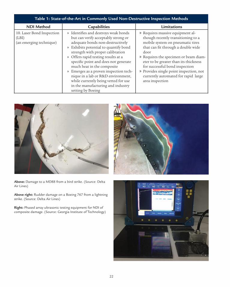
NDI Method Capabilities Limitations10. Laser Bond Inspection (LBI)(an emerging technique)
» Identifies and destroys weak bonds but can verify acceptably strong or adequate bonds non-destructively
» Exhibits potential to quantify bond strength with proper calibration
» Offers rapid testing results at a specific point and does not generate much heat in the composite
» Emerges as a proven inspection tech-nique in a lab or R&D environment, while currently being vetted for use in the manufacturing and industry setting by Boeing
» Requires massive equipment al-though recently transitioning to a mobile system on pneumatic tires that can fit through a double wide door
» Requires the specimen or beam diam-eter to be greater than its thickness for successful bond inspection
» Provides single point inspection, not currently automated for rapid large area inspection
Table 1: State-of-the-Art in Commonly Used Non-Destructive Inspection Methods
Above: Damage to a MD88 from a bird strike. (Source: Delta Air Lines)
Above right: Rudder damage on a Boeing 767 from a lightning strike. (Source: Delta Air Lines)
Right: Phased array ultrasonic testing equipment for NDI of composite damage. (Source: Georgia Institute of Technology)
22

NIST AMTech CAIIAC ProjectComposite Joining and Repair Roadmap
3.1.2 Challenges and Emerging Solutions for NDI of Composites
Challenges for in-service NDI of composites in-clude the ability to detect kissing bonds, cracking, moisture ingress, heat damage, porosity, wrin-kles, and foreign material/objects. As composites become more widely used for primary aerospace structures, non-destructive testing is necessary for continued safe use. The objectives of future in-ser-vice NDI technologies should be reduced inspec-tion time, inspection costs, and fixturing/tooling; increased repair options; and improved repair outcomes. In the end, it is imperative to ensure long-term structural reliability and safety following the actual repairs.
The current challenges to successful in-service NDI of composites are: 1) the need for speed; 2) the in-creasing complexity of the structures being tested; 3) the verification and validation of composite re-pairs; and 4) quantification to precisely characterize damage or restoration of composite structures. The ideal NDI technique should be fast, simple, quanti-fiable, and cover large inspection areas. Validating the quality of repairs over time is also a significant challenge. There is currently little research on the evolution/degradation of as-produced or repair patch materials under long-term load or thermal cycles. Microcracks that slowly expand can occur in CFRP composites. Yet, over time these microcracks may connect and lead to catastrophic structural failure. Moisture ingression over time is also an is-sue that can affect mechanical properties. A contro-versial issue in the airline industry is that routine inspections of composite aircraft (e.g. Boeing 787) are not required for the first 12 years of service. To-day, if an aircraft is inspected earlier, it is usually in a reactive manner after suspected damage due to an incident such as an impact or lightning strike.
It is also important for inspectors to be knowledge-able about the manufacturing process, materials characteristics, and in-service conditions so that they recognize the indicators of damage and un-
derstand the probable causes. The inspector should also be well versed in the operation and operating mechanisms of various pieces of NDI equipment so that they understand which NDI technique or probe to use and can interpret the instrument’s results. ASNT certification provides this type of training. Often managers will attempt to rush the inspection, which is a mistake. Many experts feel the greatest regulatory challenge is the lack of appropriate reference standards or standardized procedures for performing the inspection properly and consistently.
Inspectors need a range of equipment to choose from, even if they only have to employ a single NDI technique. As an example, for ultrasonic or eddy current testing, NDI experts believe that success largely depends on the selection of the most appro-priate probe or transducer for the specimen under inspection. Thus, a major challenge for inspectors is having limited equipment or probe selection options. For the automotive industry, the cost of current NDI equipment and a skilled NDI expert’s labor/time is prohibitive.
Replacing manual inspections with automated NDI techniques that could be implemented in-line with the composite part manufacturing process would reduce manpower and cycle times. It would also improve the accuracy, reproducibility, and reliability of inspection results. Trained inspectors would need to verify the accuracy of automated NDI to gain confidence in the reliability of these techniques. Wireless NDI inspection where an NDI expert can control the NDI instrument remotely and analyze the results is appealing for reducing cycle times and manpower. Further, structural health monitoring (SHM) technologies are being developed that would allow for real-time quanti-fication of degradation in composite structures. Robust SHM with new prognostic capabilities represents a significant long-term need and would realize a popular vision of the future aviation industry expressed in the Digital Twin Paradigm. However, current challenges with SHM include
23

the need for too many sensors to get precise dam-age location and size. There is also difficulty in wirelessly transmitting data from sensors that are embedded or surface bound to composite parts. Ex-cessive wiring would increase weight of the aircraft. Surface bound sensors may negatively influence aerodynamics of aircraft structures. The electrical-ly conductive composite structure causes serious limitations for wireless signal transmission from embedded sensors.
Aerospace industry experts emphasized that the most urgent challenge for NDI is the lack of in-spection techniques capable of quantifying bond strength, particularly the strength of the bondline for adhesively bonded repairs. The inability to non-destructively inspect the bondline and de-tect kissing or weak bonds after repair is a critical industry-wide concern. With current NDI tech-niques, you can detect disbonds when an air gap is present, but kissing (i.e. disbond with no air gap) and weak bonds cannot be detected. The Federal Aviation Administration’s (FAA) concern about
the safety of bonded repairs caused them to devel-op a new regulation (Nov. 2014) to limit the size of allowable bonded repairs (Bonded Repair Size Limit, PS-AIR-20-130-01). In transport aircraft, the maximum allowable repair size is the size at which the structure can still operate at limited load even if there is a complete failure of the repair. This dramatically limits the size of the bonded repair that can be undertaken. This is a major source of controversy in the industry because much larger repairs have been done successfully. The FAA’s concerns would be alleviated if a way to physically measure the bond strength without destructing it (i.e. causing a complete disbond of critical flaw size) were developed. This is a major unsolved problem in the industry. There are a few emerging NDI tech-niques currently being developed to address this issue as shown in Table 2 below. Further, Lockheed has been working on a Defense Advanced Research Projects Agency (DARPA) funded program to build trust in composite bonded repair called the Transi-tion Reliable Unitized STructure (TRUST) project.
Table 2: Challenges and Corresponding Solutions for NDI Technology
Challenges/Needs Emerging/Potential Solutions
» Increase speed of testing and simplify the measurement and analysis
» Develop and employ robotized or automated NDI techniques that enable faster and more accurate inspections
» Provide a straightforward “go” or “no-go” decision using specialized/automat-ed NDI tools based on UT for airline maintenance personnel in the event of an impact to a composite component. The tool can:
• Detect delamination in a composite fuselage• Reduce inspection time from one hour to two minutes • Eliminate the need of an expert technician to do the measurement
» Reduce the need to dis-patch an NDI expert to a remote site to perform detailed analysis which can be expensive and time consuming
» Use wireless technology to allow remote monitoring and control of inspection by an NDI expert. The tool can:
• Perform NDI on site using a “non-expert”• Provide remote assistance to the non-expert via the NDI expert who remotely
controls the NDI instrument and communicates wirelessly with the non-ex-pert
• Generate and send a 3D mapping of the composite structure to the expert, to analyze the scanned results in a CAD environment
• Reduce errors, delays and overall cost by eliminating necessity of expert to be dispatched to each damage site
24

NIST AMTech CAIIAC ProjectComposite Joining and Repair Roadmap
Table 2: Challenges and Corresponding Solutions for NDI Technology
Challenges/Needs Emerging/Potential Solutions » Add the capability to detect damages on complex surfaces or contours
» Develop and employ robotized NDI for complex geometries• Combine robotics and ultrasound scanning with a surface-adaptive algo-
rithm (e.g. Surface-Adaptive Ultrasound, from Contour Dynamics Inspection Systems in Levis, Quebec, Canada)
• Enable faster and more accurate inspections of composite parts that have complex shapes and sharp radii.
» Expand availability of a trained workforce
See Section 3.6
» Add the capability to precisely detect the loca-tion of kissing bonds
» Explore use and advance Digital Shearography technology, which combines Con-ventional Shearography with Digital Image Correlation (DIC). Digital Shearogra-phy can:
• Detect small delaminations and disbonds, with potential for detection of kissing bonds
» Explore use and advance Laser Bond Inspection (LBI) technology. LBI can:• Detect weak bonds with potential for detection of kissing bonds
» Add the capability to quantify adhesive bond strength • Enable a pervasive
acceptance and certification by FAA of bonded repairs on large composite structures
• Verify strength of the bondline which is a critical indication of safety in the repaired structure
» Explore use and advance LBI technology. LBI can: • Detect weak bonds and variations in bond strength • Perform well in R&D/lab settings; but being vetted by prime contractors,
airline MROs, and OEMs such as Boeing for industry use• Function as a portable system, but still too bulky for rapid on-site inspec-
tions
» Add the capability to quantify degradation preferably in real-time
» Explore use and advance structural health monitoring (SHM) technology.• Integrate sensors to continuously monitor material and structural degrada-
tion in real-time• Develop, install and integrate high performance sensors on composite struc-
tures, while minimizing cost and complexity• Develop CJAR practices that avoid damage to SHM electronics via cutting
key sensor fibers and/or wires• Eliminate wires/fibers by integrating energy harvesting and wireless commu-
nication systems on composite vehicles for powering and transmitting data, respectively, from sensors networks to cockpit controls
25

Table 2: Challenges and Corresponding Solutions for NDI Technology
Challenges/Needs Emerging/Potential Solutions » Consider advanced
characterization/in-spection beyond just detection to create a portfolio of more useful damage metrics
» Develop and integrate non-destructive evaluation (NDE) algorithms or software tools with existing NDI equipment
» Develop better tech-niques for NDI of hybrid structures (e.g. glass fiber / carbon fiber reinforced plastics)
» Develop techniques such as the relatively new THz NDI tool that is useful for detecting material changes in hybrid structures
» Determine how to bet-ter predict and measure the tolerance of repair after impact damage.
See Section 3.4
» Provide automated NDI techniques with built-in NDE; this technology will,• Prevent a full-time
inspector from spending 99% of his time inspecting faultless areas man-ually with hand-held probes
• Reduce manpower and cycle times and improve repeatabil-ity and reliability by minimizing human error
» Provide automated damage detection techniques coupled with data analysis software capable of automatically detecting and signaling defects (e.g. see Airbus “Line Tool” above)
» Update existing NDI tools with remote control or autonomous functionality to:• Reduce human interaction with the structure• Reduce NDI cost while ensuring ease of use, safety, and rapid/robust data
collection
3.1.3 NDI Roadmap Summary
In the NDI roadmap chart, Figure 7, we have summarized our findings of the industry’s cur-rent status and needs/challenges for NDI under the SOTA column. The promising technologies and future R&D activities that serve as solutions to industry needs are shown in the third column, which corresponds to each type of NDI technique listed in the second column. The chart also features qualitative ratings for performance, safety, speed,
and cost; and quantitative ratings of technology, manufacturing, and business-case readiness levels for each of the technologies/R&D activities listed in the third column. Finally, the roadmap includes a timeline for technology maturation through the year 2030. Also refer to the Automation roadmap chart, particularly the section on Automated NDI in Section 3.5.3, for a projected timeline of auto-mated NDI technology maturation.
26

NIST AMTech CAIIAC ProjectComposite Joining and Repair Roadmap
Figure 7. Detailed roadmap showing technology maturation of various NDI techniques for composite structures.
27

3.2 Materials
Material selection for composite repair is made based on the initial materials used to manufacture the part and the final properties to be achieved (mechanical properties, thermal resistance, chem-ical resistance, life cycle degradation, etc.). Carbon fiber-reinforced polymer composites are currently being used for both primary and secondary struc-tural applications and in both manufacturing and repair of aircraft. Advanced composite materials such as continuous carbon fibers with a polymer matrix can provide material properties that are superior to metals and thus enable lighter structur-al designs to be achieved [8]. The lighter structures result in lower fuel consumption and thus reduced emissions. In the automotive industry, it has been estimated that for every 10% of weight eliminat-ed from a vehicle’s total weight, fuel economy improves by 7%. This also means that for every kilogram of weight reduced in a vehicle, there is about a 20 kg reduction of carbon dioxide [21]. In addition to the improvement in fuel-efficiency and emission reduction, composite materials in aircraft design also improve passenger comfort. A composite fuselage, has a higher allowable hoop stress and corrosion resistance, and allows more comfortable levels of cabin pressure and humidity. The Boeing 787’s composite structure has airframe maintenance costs that are 30 percent lower than any comparable airplane. This is largely due to the lack of corrosion and fatigue, the two primary driv-ers for repair and maintenance of traditional metal airframes [22]. The cost of composites will contin-ue to decrease as its usage becomes more standard. Increasing demand will cause more manufacturers to enter the market and increase production (i.e. economies of scale).
3.2.1 State-of-the-Art of Materials Used in Composite Joining and Repair
The Composite Materials Handbook-17 (CMH-17) provides a wealth of information and guidance necessary to design and fabricate end items from composite materials. Its primary purpose is to standardize engineering data and development methodologies related to testing and reporting of property data for current and emerging composite materials. In support of this objective, the hand-book includes composite materials properties that meet specific data requirements.
Carbon fiber reinforced polymer composites are usually manufactured in laminate or sandwich forms for aerospace structural applications [23]. Thermosetting (e.g. epoxies) or thermoplastic (e.g. PEEK, PPS, PEI, PEK, PAI, etc.) resins are often used as a matrix material to hold reinforcing fibers. While the two matrix-material types have their pros and cons, thermosetting resins are currently exten-sively used in aircraft manufacturing [24] because of the relatively low material and processing costs involved. The conventional manufacturing process-es are based on the prepreg approach (i.e. uni-direc-tional fiber with pre-impregnated resin). However, composite manufacturing use of prepreg materials is often expensive, alternative forms of materials and manufacturing methods are being sought to produce composites at a reduced cost [25]. For af-fordability and cost-efficiency, novel materials (e.g. new fiber precursors [26], resin chemistries [27]) and manufacturing techniques (e.g. resin infusion of fiber pre-forms [28, 29] for thermosetting resins, automated tape laying [30] for thermoplastics) are gaining popularity.
28

NIST AMTech CAIIAC ProjectComposite Joining and Repair Roadmap
Adhesive Material Properties/Capabilities Service Temperature (oC)
Cure Conditions
Epoxies High strength and tempera-ture resistance. Relatively low cure temperatures, easy to use, low cost
-40 to +100 One part epoxies cure with temperature (e.g. 250 or 350˚F for aerospace epoxies). Two-part epoxies cure at room temperature (RT) or accelerated cure with temperature
Cyanocrylates Fast bonding capability to plastic and rubber but poor resistance to moisture and temperature
-30 to +80 Cure rapidly (seconds or minutes) upon exposure to moisture at RT
Anaerobics Designed for fastening and sealing applications in which a tight seal must be formed without light, heat or oxygen. Suitable for bonding cylindri-cal shapes
-55 to +150 Cure in absence of air or oxygen at RT
Acrylics Versatile, fast curing, can tol-erate dirtier and less prepared surfaces.
-40 to +120 Cure through a free radical mechanism; poor environmental resistance, not robust in the long term
Polyurethane Good flexibility at low tem-peratures and resistance to fatigue
-200 to +80 RT, may fatigue under compres-sion
Silicones Sealant for low-stress applica-tions, high degree of flexibility, very high-temperature resis-tance
-60 to +300 RT
Phenolics, Polyimides, Bismaleimides
High temperature adhesives -40 to +175-40 to +250-50 to 200
Cure with high temperature and high pressure
Table 3: State-of-the-Art Adhesive Materials Used in Structural Applications [31]
Epoxy adhesives are the most commonly used adhesives to join composite materials. A good bond is highly dependent on the choice of the adhesive material. Surfacing adhesives may also be used, such as electromagnetic interference shielding and lightning strike protection adhesives applied on the outer surface of composite components. Material suppliers such as Henkel and Cytec Solvay supply a wide range of adhesives (Table 3) for metal-to-met-al, metal-to-composite, and composite-to-compos-ite joining. Adhesive selection is based on: type and nature of substrates to be bonded, cure and adhe-sive application method, expected in-service envi-
ronments, and cost. Further research is required to understand the behavior of various bonded systems (various adhesives and various adherends) exposed to various temperature and moisture conditions.
In general, few advances have been made over the last 50 years in formulating resins for composite applications. Virtually all epoxies are composed of the same basic chemical entities: MY720, DGEBA and DDS. Various toughening agents are added to this basic resin formulation, but all have some drawbacks, such as reducing the safe operating temperature of the composite. Existing resins also
29

have inherent “free volume” which exacerbates moisture accumulation within the bulk composite. Moisture is known to degrade performance and in-hibit bonding. Advancement in SOTA resin formu-lation is required to mitigate the drawbacks, for instance to reduce moisture uptake and to improve the reliability and strength of bonds to the material.
Thermoset materials have been standard resins for composites applications in the aerospace indus-try. They have an extensive and successful track record dating back to the 1960s. The industry made substantial investment in thermoset equip-ment, infrastructures, process developments and workforce training, building a mature value chain. Thermoset composites are particularly attractive for highly stressed parts: lower processing viscos-ities for high fiber volumes, superior adhesion (to fibers, paint, etc.) and high thermal resistance. The most frequent thermoset resins include: polyester; epoxy; phenolic; vinyl ester; polyimide and bisma-leimide. Development in thermoset resins focuses on decreasing the curing time or temperature and optimization of the viscosity to allow good
impregnation without damaging the final mechan-ical properties.
Compared to thermosets, thermoplastics offer gen-erally superior impact toughness, fire, smoke and toxicity performance and chemical resistance. In addition, their shelf life is almost infinite at room temperature, whereas the shelf life of thermoset prepregs is about six months in refrigerated stor-age. Thermoplastic parts can be roughly 20 to 40 percent cheaper due to reduced handling, process-ing and assembly cost, although the raw material in fiber or prepreg form is more expensive than competing thermosets. Assembly and repair can be made easier by welding thermoplastic parts, which cannot be done with thermosets. Thermoplastics are also easier to recycle than thermosets. Figure 8 shows a comparison of thermoset and thermoplas-tic resin properties in terms of tensile strength and cost per pound.
Thermoplastic usage in the aerospace industry is expected to increase by 200 to 300 percent in the coming decade. The thermoplastic resins primarily used in the aerospace industry are Polyether Ether
Figure 8. Comparison of thermoset and thermoplastic resin properties in terms of tensile strength and cost per pound. [25]
Nor
mal
ized
Ten
sile
Str
engt
hks
i/de
nsity
/gcm
3
Price ($/lb)
25
20
15
10
5
0$1 $10 $100 $1,000
Structural Resins
InteriorResins
PEEK
Polyimide
Cyanate EsterEpoxy
Polyetherimide
PPS Bismaleimide
Thermoset Resin
Thermoplastic Resin
Phenolic
Polyester
Polycarbonate
30

NIST AMTech CAIIAC ProjectComposite Joining and Repair Roadmap
Ketone (PEEK), Polyetherimide (PEI) and Poly-phenylene Sulfide (PPS) [32]. Prepregs are a combination of fibers (glass, carbon or other specialized fibers) and uncured resin that need heat to be activated and cured. There are several advantages to using a prepreg rather than using traditional hand layup:
» High strength properties: prepregs have a lower resin content (about 35%) that increases mechanical strength compared to hand layup components
» High uniformity and repeatability: prepregs ensure an even resin distribution
» Reduced curing time » Cleaner process and reduced waste » Improved appearance
Production of prepregs is labor intensive and better suited for low volume industries like aerospace rather than high volume ones like automotive. Prepregs have a long cycle time, which means high labor costs, low productivity of the molding tool investment, and they are expensive. Their shelf life is limited and they must be kept in refrigerators with their condition monitored carefully.
Core Materials: A large proportion of current aerospace composite components are light sand-wich structures that are susceptible to damage and are easily damaged. The most common core mate-rials used for aircraft honeycomb structures are ara-mid paper (Nomex or Korex) and fiberglass, which are used for higher strength applications. Hon-eycomb core cells for aerospace applications are usually hexagonal and made by bonding stacked sheets at special locations and expanding them. Foam cores are used on home-built and lighter air-craft to give strength and shape to wing tips, flight controls, fuselage sections, wings, and wing ribs. Foam cores are not commonly used in structural components of commercial type aircraft, although Rohacell is becoming a common structural core material used in radomes. Balsa core is a natural
wood product with elongated closed cells. Balsa wood has a considerably higher density than other types of structural cores. Other hybrid structures such as glass laminate aluminum reinforced epoxy (GLARE), are made with metal and composites and have better impact damage resistance than tradi-tional sandwich structures.
3.2.2 Challenges and Emerging Solutions for Materials Used in Composites Joining and Repair
Material requirements differ from one application to the next. The choice of composite materials used for repair depends on the environment and is constrained by the business needs of each industry. Here we are focusing primarily on the Aerospace industry. Table 4 on page 35 summarizes industry needs and emerging solutions for composite repair materials.
Repair Shops vs. Manufacturers: Repair shops or MROs require much smaller quantities of materials than manufacturers; however, a significant chal-lenge is the limited range of package sizes that are available for purchase from material suppliers. Re-pair shops often need the same product as OEMs, but in a smaller package. Further, they require an extensive inventory of materials to be able to do repairs quickly on any aircraft make and model.
LOCTITE EA 9825 AERO is an epoxy syntactic for use on honeycomb composite parts requiring high compres-sive strength at temperatures up to 177°C, also used for fastener or attachment potting and panel edge reinforcing. (Source: Henkel Corporation)
31

This situation is exacerbated by the fact that there are specific materials and specific suppliers for each aircraft OEM and aircraft model. A major problem exists with the high volume of materials, such as prepregs and adhesives, that are discarded because the repair shop has limited space for inventory or storage. The shelf life of the materials is often short so even if storage space is sufficient, due to the low or random demands for repairs, materials are not used in time and are then discarded. For example, about 90% of the prepregs required to be stocked for repairs get thrown away because of their 6-month shelf life. Airbus is very much aware of this problem and has standardized repair schemes/materials for the A350 airframe. The company has also developed “composite box-es” (available through their distributor SATAIR), which gathers limited quantities of each material required to perform a repair. Further, the aim of the CACRC is to develop standardized repair materials to be used industry-wide or on as many aircraft makes and models as possible.
Moreover, it is difficult and expensive for repair shops to mimic the manufacturing shop floor temperature requirements for materials storage and production (e.g. large refrigerators, freezers, or autoclaves). Thus, repair shops also have a strong need for new types of prepregs or resin adhesives that can be stored at room temperature and can be cured at lower temperatures (e.g. Benzoxazine) and outside of the conventional large autoclaves that are common to manufacturing facilities. Henkel is currently addressing this need by developing 75 percent or more of its adhesives for OEM joining and the other 25 percent of adhesives specifical-ly for repair. Sometimes, the Henkel product is identical in composition for both segments, but is also available in a smaller package for the MRO customers. The need for multiple materials for a single repair and rapid distribution to the MRO from suppliers to reduce maintenance downtime is another major issue that reflects significant supply chain challenges.
Barrier to Entry for New Materials: It is antic-ipated that consistent industry-wide standards for testing requirements and performance metrics would enable accelerated insertion of commercial composite products speeding up both the product development and the supply chain. In general, there is a long development cycle and increasingly steep qualification hurdle for intro-ducing new material products into the aerospace industry whether for manufacturing or repair. Due to the variety of material requirements specified by various OEMs, material development cycles must be performed several times over to meet every customer’s unique testing requirements and performance metrics. At best, materials product development takes a minimum of 5-10 years, and the subsequent qualification/certification of the products takes an additional 1-5 years before the product hits the shelf. New composite prepreg ma-terials have longer development and qualification periods than adhesives/resin products. The materi-al testing alone costs ~ $100 million to ensure that the life cycle of the product matches that intended for the aircraft (usually 30 years).
Another issue is that once products such as an adhesive formulation finally enter the commercial market, industry is resistant to change products because of the strict development and qualification regulations. For example, changing the raw mate-rial, chemistry, or manufacturer/supplier of that product will change the processing parameters, which is undesirable due to the need for retesting and requalification. Hence, the material products offered are very specific and it is rare that there is more than a single source for the same material, which can be problematic if the sole supplier has a shortage. Overall, the materials segment of the industry is inherently prone to being stagnant, thereby limiting the rate of innovation needed to deliver dynamic and optimal solutions. Such little incentive to research and develop these products means there are currently very few long-term devel-opment projects for new adhesives and new prepreg products entering the aerospace industry.
32
NIST AMTech CAIIAC ProjectComposite Joining and Repair Roadmap
Need for High and Low Temperature Adhe-sives: Although the adhesives used are largely epoxies and will remain as such for mainstream applications, there are some niche applications that require other types of adhesives. For example, as aircraft are getting hotter and hotter with the addition of more electrical equipment, there are some hot spots where epoxy adhesives won’t work. Higher temperature adhesives are required, such as bismaleimide. A newer material currently under investigation, Benzoxazine, could be an alternative solution in the future. It uses cheap feedstock and is easy to prepare, making it a viable alternative to bismaleimides, which are relatively expensive and difficult to process. As mentioned above, lower or room temperature adhesives are also being devel-oped that would allow for easy storage by MROs as well as out-of-autoclave curing which is essential for mobile onsite repairs that can restore aircraft operation the fastest.
Thermoset vs. Thermoplastics: Thermoplastics are beginning to penetrate the composite market, albeit slowly. Given their advantageous properties and performance as a structural repair material, their use is expected to expand. While the adoption of a new material is very slow, it is further slowed by the need for new supporting equipment and infra-structure necessary to enable processing, inspect-ing, testing, joining, and repair with thermoplas-tics. A major problem is that since there isn’t great demand for them yet, it is still quite expensive to make the quantities needed. Further, thermoplas-tics are often processed at higher temperatures (e.g. 340˚C for PEKK) than thermosets. They offer ep-oxy like performances, but their high temperature cure cycle implies that the joining and repair pro-cesses used (e.g. vacuum bagging) would also need to be able to withstand these higher temperatures. This may be easily justified given that the manufac-turing or repair cycle times are much shorter.
Automotive companies are very interested in tran-sitioning to thermoplastics. One reason is the capa-
bility to perform structural repairs (e.g. removing a dent) more rapidly while eliminating the laborious and costly requirement for scarfing (i.e. removal of damaged material and joining of a repair patch) required with the use of thermoset composites. Aerospace OEMS are also interested. For example, Airbus is actively working on an innovative process for automated tape laying of thermoplastics.
Inclusion of Nanomaterials: Nanomaterials such as carbon nanotubes, nanofibers, and cellulose nanocrystals are capable of significantly improving mechanical properties of composite structures, which allows for additional reductions in weight of the structural material. These improvements can occur even when the nanomaterial concentration in the composite material is small (e.g. 1- 5 wt%). For bonded repair applications, oriented nanomaterials could be used in “nanotoughened” adhesive formu-lations to improve the bonding strength between composite laminates by “z-axis pinning.” However, many nanomaterials such as Single Walled Carbon Nanotubes, which exhibit extraordinary mechani-cal properties, still have high production cost and incur high processing cost when attempting to effectively infuse them into composite laminates or resins. A major problem is the sudden increases in viscosity or stagnated flow of resins due to the difficulty in maintaining good dispersion during processing. This is a significant issue that hin-ders incorporation of nanomaterials. Growing nanomaterials onto the fiber surface is one way to mitigate the anti-thixotropicity issue, otherwise the nanomaterial limit is approximately 12% to 15% per volume. Thus, in practice, the incorporation of nanomaterials has proven to be difficult and has only yielded nominal or modest improvements.
There has been a huge amount of research in nano-material-based composites, but no large-scale man-ufactured products have reached the market yet. Finding actual applications of nanomaterials in the marketplace is needed to move this field of research forward. Multifunctional composite structures
33

for critical or high-end applications or self-healing composites could be achieved with nanotechnolo-gy. However, more research is required in these ar-eas. Preliminary work on fast and uniform heating via rapid electrical curing of nanomaterial doped composites has been demonstrated. Nanomateri-als also have applications for improving fracture toughness in composites. In any case, while im-proving the performance, the inclusion of nanoma-terials into composites should be cost-effective and should not impact the overall manufacturability.
Synthetic vs. Natural Fibers and Composite Material Recycling: Fiber reinforced polymer matrix composites can use synthetic or natural fibers as reinforcement [21]. While synthetic fibers are a more traditional type of composite, natural fiber composites are gaining popularity and have a substantial potential for growth because of their low environmental impact. A growing concern in all of the industries, including automotive, is an increased awareness for the environment. Issues such as protection of resources, reduction of CO2 emissions, and recycling are increasingly topics of consideration. While the United States has not is-sued regulations concerning automotive end-of-life requirements, the European Union (EU) and Asian countries have released stringent guidelines. EU legislation implemented in 2006 dictates that a sig-nificant percentage of the vehicle should be re-used or recycled. The new legislation means that any dis-cussion of using new materials in the automotive industry should also consider recycling. Consider-able R&D efforts are now focused on developing materials that are recyclable and also on developing ways to recycle current materials. This also explains the amount of attention given the use of natural fiber-based composites and new high temperature resistant thermoplastic resins in the automotive industry. The lightweight, low cost, natural fibers offer the possibility to replace a large portion of the glass and mineral fillers in several automotive interior and exterior parts. In the past decade, nat-ural-fiber composites with thermoplastic and ther-
moset matrices have been embraced by European car manufacturers and suppliers for door panels, seat backs, headliners, package trays, dashboards, and interior parts. Natural ecofriendly fibers such as kenaf, hemp, flax, jute, and sisal are being used for automobile part reinforcement because they offer reductions in weight, cost, CO2, less reliance on foreign oil sources, and recyclability. With an eye towards such ecofriendliness, most automakers are evaluating the environmental impact of a vehicle’s entire lifecycle, from raw materials to manufactur-ing to repair and disposal.
Thermoset composite materials are relatively difficult to recycle because of their chemical sta-bility and the difficulty to separate the matrix and the fibers. Currently, the most common recycling approach for thermoset composites is to shred retiring composites into fillers for downstream applications. Thermoplastic resin composites are easier to recycle as they can be re-melted and poten-tially reused as injection molding feedstock. This explains the increased interest for thermoplastic resin composites for large-scale production parts; however, businesses are more likely to comply if recycling incentives and regulations are established. To promote recycling of composites, the cost should be lowered, the recycled constituents’ qual-ity should be improved, and the applications that could use the recycled feedstock should be identi-fied and demonstrated. Recycled materials may be better suited and have a lower barrier to entry for repair of composite structures versus manufactur-ing of new products.
34

NIST AMTech CAIIAC ProjectComposite Joining and Repair Roadmap
Challenges/Needs Emerging/Potential Solutions
» Lower barrier to entry for new materials while maintaining safety
• Requires high expense and enormous amounts of time to qualify/certify new materials
» Modify regulations (e.g. FAA) carefully to lower the barrier for new material entry to improve innovation while maintaining safety
» Develop materials with improved curing properties• Increase cure speed and expand cure tempera-
ture ranges • Provide, for example, resin systems with low
viscosity, low cure temperature, and short cure time for cost-effective on-aircraft scarf repairs
• Develop low cost, high temperature resins for repair of hot spots on aircraft
» Develop new epoxy resin formulations (e.g. benzox-azine) compatible with out-of-autoclave (OOA) low temperature requirements. The newly developed resins will:
• Gain popularity• Require more development before they are wide-
ly accepted by the industry » Develop OOA prepregs to ease prepregs processing
and achieve high quality, low void content material without the use of autoclaves.
» Employ Bismaleimide (BMI) for manufacture/repair of high temperature resistant parts
» Develop improved adhesives• Develop higher z-axis strength adhesives for
better bond quality• Reduce susceptibility to contamination,
including water and oil influx that damages composites
• Formulate specialized adhesives for fast repairs
» Develop nanotoughened epoxy adhesives that in-clude high strength z-axis—oriented nanomaterials
» Develop new methods to increase weight percent of nanomaterials in adhesives or CFRP prepregs without introducing undesirable agglomeration or viscosity.
» Employ self-healing or self-repairing resins » Develop repair resins with more surface contamina-
tion tolerance » Develop advanced resin systems for moisture resis-
tance » Develop reversible adhesives that enable creation of
selective disbonds of key areas for repair/rework » Develop repair adhesives/resins with known process
tolerances (cure conditions, moisture, etc.)
» Increase material availability and reduce waste in repair shops
• Address limited inventory of material manu-facturers and limited shelf-life of prepregs (6 months when kept in a refrigerator)
• Improve the complex and slow material supply chain
• Increase availability of materials, more than one supplier or source per material needed
• Supply rapidly the need for multiple materials for each step of the repair and for different functions (e.g. peel-ply films, prepreg patch, lightning strike and anti-ice protective coat-ings).
• Develop or increase use of materials that offer increased repairability, recyclability, or reuse options
» Develop prepregs with longer shelf life » Provide smaller package sizes for repair shops » Standardize material products from various OEMs
and make available from multiple suppliers » Implement use of natural fiber composites where
possible » Provide materials-on-demand and/or rapid distribu-
tion networks » Use multi-functional materials to limit number of
materials required for repair
Table 4: Composite Repair Material Challenges and Emerging/Potential Solutions
35

Challenges/Needs Emerging/Potential Solutions
» Increase use of thermoplastics• Requires new equipment infrastruc-
ture making it too expensive to invest in thermoplastics
• Requires processing at higher tempera-tures than thermosets, tooling must be qualified for higher temperature processing
» Develop and/or utilize self-healing or self-repairing resins for healing of thermoplastic polymers or paint cracking
» Demonstrate or provide case-studies to show that the move from thermoset to thermoplastics for structural application greatly reduces cycle time, improves recyclability, decreases repair times, enables cleaner factories and easier handling / processing
» Show that the ROI is high and worth the initial investments. » Develop an innovative single step process for automated
tape laying of thermoplastic composites and (e.g. a current Airbus project)
» Gain a better understanding of hybrid ma-terial (Metal-FRP composites) properties• Understand whether chemicals within
composites play a role in accelerated metal corrosion
• Understand how to optimize hybrid structures (Al and carbon composites) for best mechanical properties with minimal weight
» Develop hybrid joining techniques that can reduce the cor-rosion in metal-FRP composites
» Develop ICME based or other modeling software (see Sec-tion 3.4) to help optimize hybrid material structures and properties
» Gain a better understanding of crashwor-thiness of composites especially for au-tomotive industry to assist with material design for composite vehicles
» Perform R&D on crashworthiness of bonded composite structures, burn time, flame durability, toxicity (repair mate-rial qualifications for these as well)
» Understand the dynamic impact behavior of composite materials, joints and structures (before and after repairs) including low-speed and high-speed impacts such as strain-rate effects; stiffness, strength and fracture characterization of multi-material joints [33, 34]
» Develop computational models that account for effects of operational loads, local impacts, and environment on mate-rial and structural properties [35]
» Develop repair materials specifically for complex surface or contour
» Develop shape-memory polymer based composites for re-pair of complex structures
» Deploy standardized fiber property and size » Implement universal sizing and surface treatment of carbon fibers for multiple resins
Table 4: Composite Repair Material Challenges and Emerging/Potential Solutions
material listed in the second column. The chart features qualitative ratings for performance, cost, and processing speed. It also shows quantitative ratings of technology, manufacturing, and busi-ness-case readiness levels for each of the material technologies listed in the third column. Finally, the roadmap shows a timeline for technology matura-tion up to 2030.
3.2.3 Materials Roadmap Summary
The roadmap chart shown in Figure 9 summarizes our findings of the industry’s current status and needs/challenges for composite repair materials under the SOTA column. The promising materials technologies and future R&D activities that serve as solutions to industry needs are shown in the third column, which correspond to each type of
36

NIST AMTech CAIIAC ProjectComposite Joining and Repair Roadmap
Figure 9. Detailed roadmap showing maturation of various material technologies used for composite repair.
37

3.3 Processes
Joining composite structures together with an ad-hesive bonding process presents several advantages compared to mechanical joining in both manufac-turing and repair settings:
» Better load distribution over a larger bond area » Higher stiffness and toughness over the bond
area » Reduced weight, compared to the use of addi-
tional joining parts (bolts, rivets…) » Dissimilar materials joining » Potentially lower manufacturing costs
But these advantages have yet to be balanced with the ability to non-destructively measure bond strength, limiting the confidence in the bonding processes. Further, there is a lack of knowledge on the mechanisms of adhesion so that adhesive bonding is currently not trusted for primary loaded structures.
3.3.1 State-of-the-Art of Composite Joining Processes
State-of-the-art composite joining processes for major techniques currently used include mechan-ical joining or fastening, adhesive bonding, hybrid joining, and thermoplastic welding. Each of these joining methods and their sub-techniques are de-scribed below with benefits and limitations of these processes compared in Table 5 on page 40.
Mechanical fastening, i.e. bolted repairs are currently the most common method of joining
and repair for both metal and composite aircraft structures. Bolted repairs often employ doublers such as titanium sheet, carbon fiber patches or aluminum patches that are mechanically fastened around the damage area. Bolted repairs on compos-ite structures are currently being performed similar to bolted repairs on metal structures. However, composites are very prone to delamination caused by variations in bit sharpness and tool speed, which requires an adjustment of the drilling process for composites. Advantages include saving time and not using heat. Disadvantages include aerodynamic degradation, changes in radar signature, and orig-inal structure damage via mechanical devices (i.e. drills, bolts, slag, etc.). Human error may increase damage possibilities, due to dull drill bits, incor-rect drilling speeds, improper policing/cleanup of debris [3].
Adhesive bonding, i.e. bonded repairs have been performed successfully in the aerospace industry for over 25 years, but they have been very limited in size, rarely greater than 18 inches in diameter. Cur-rently bonded repairs are too time consuming and demand a very high level of quality assurance. They also usually require that the aircraft be removed from service (i.e. hangered). Repairs outside of controlled environments are exposed to elements that produce poor bond quality. Whereas tradi-tional metal aircraft may often have minor damage repaired in normal flightline conditions. The cur-rent surface treatment and inspection methods for composite aircraft are not conducive to flightline operations (not mobile enough or not effective in uncontrolled environments).
MD88 engine inlet outer panel with erosion at fasteners. (Source: Delta Air Lines)
38

NIST AMTech CAIIAC ProjectComposite Joining and Repair Roadmap
Hybrid joining is of interest to industry that performs both homogeneous and heterogeneous bonding, i.e. composite to composite joining and composite to metal joining. Composite to metal joining is particularly interesting to the automotive industry because of the ability to synergistically combine the best properties of both materials in an easy and efficient way. In some cases, long curing cycles of adhesives is too costly to be effective. Thus, there is a strong need for hybrid joining technol-ogies where adhesive bonding is combined with rapid mechanical fastening. A secondary function of the adhesive layer (if electrically insulating) is also to act as a corrosion-protective layer to prevent the metal from corroding while in contact with the composite material. The automotive industry is looking for new methods of joining dissimilar materials in a fast and cost effective way.
Co-curing (an adhesive bonding method) con-sists of curing a composite laminate/prepreg and simultaneously bonding it to some other uncured material, or to a core material such as balsa, honey-comb, or foam. All resins and adhesives (if required) are cured during the same time. Co-cured joints without the adhesive show strengths higher than with co-cured adhesive or secondary adhesive joints. Achieving good metal-to-composite bonds is diffi-cult because metals usually have a higher coefficient of thermal expansion than composites, especially carbon and aramid composites. The bonds can break if the structure is subject to large tempera-ture swings. This is the reason why co-cured met-al-to-composite bonds can fail even before the part is put into service [36].
Co-bonding (an adhesive bonding method) consists of the curing together of two or more elements, of which at least one is fully cured and at least one is uncured. This requires careful sur-face preparation of the previously cured substrate and an additional adhesive may be required at the interface [36].
Secondary-bonding (an adhesive bonding meth-od) uses a layer of adhesive to bond two previously cured (i.e. pre-cured) composite parts [36].
Curing is required for all adhesively bonded ther-moset composite structures [36]. Effective curing reactions require application of both elevated temperatures and pressures for a period of time, administered during the cure cycle. Controlled heating is required to cure adhesives and co-cure composite patches. In humid conditions, it may be necessary to dry the surfaces and get rid of mois-ture in the sandwich core prior to repair at elevat-ed temperatures without overheating the parent component. For out-of-autoclave or on-aircraft composite repairs, a single-sided heating source is often used to transfer heat through the full thick-ness of the repair patch to achieve a uniform cure of the adhesive and co-cured patch. However, the composite laminates typically exhibit poor thermal conductivity in the through-thickness direction, which may lead to a thermal gradient especially if a substructure beneath the repair patch acts as a heat sink [3, 37]. A thermal gradient could lead to non-uniform curing of the adhesive or co-cured patch and, consequently, introduce a non-uniform stress transfer, making the bonded repair ineffec-tive. Further, complex cure temperature gradients or surface contamination may also increase the potential for process-induced warpage, residual stresses, matrix micro-cracking, micro-delamina-tion of the repair patch, and formation of kissing bonds. Cure pressure is also an important pa-rameter and must be adequate to ensure proper bondline thickness, minimize bondline porosity, and cause the adhesive to flow and properly wet the surfaces [38, 39]. Appropriate cure pressure achieved in the autoclave or via vacuum bagging ensures a good compaction of the laminate plies as it reduces porosity by removing both volatile gases generated during curing and entrapped air between the film adhesive and the machined surface. Pre-pregs are cured between 250°F and 350°F. Multiple cure cycles might be required for thicker structures or extensive repairs.
39

Welding is a composite joining technology adapt-ed to thermoplastic composites only. The process of welding thermoplastic composites consists of preparing the surface, heating the area to be weld-ed, applying pressure on weld areas and cooling.
Different technologies exist to weld thermoplastic composites:
» Frictional heating: linear vibration welding, spin welding, ultrasonic welding, friction stir welding
» Thermal techniques: hot-tool (plate) welding,
hot gas welding/extrusion welding, infrared welding, laser welding
» Electromagnetic heating: induction welding, dielectric & microwave welding, resistance welding
The most common methods for welding thermo-plastic composites include friction spot welding, hot plate welding, ultrasonic welding, and laser welding. Advantages and limitations of each of these methods is summarized in Table 5 below.
Joining/Bonding Process
Advantages/Properties Limitations
» Mechanical fasten-ing (i.e. Bolted repair)
» Performs larger repairs exten-sively and exclusively to ensure restoration of in-service perfor-mance requirements
» Performs structural repairs in a relatively fast and simple way
» Eliminates need to remove dam-aged material from the parent structure via use of doublers
» Eliminates heating/curing » Enables easy disassembly, ideal
for temporary repairs
» Increases fuel consumption and emissions due to additional weight of fastening compo-nents
» Increased stress concentrations due to smaller load distribution areas concentrated at me-chanical joints
» Causes vehicles to be cosmetically unattractive » Causes difficulty and possible damage when drilling holes through dissimilar materials
» Increases probability for tearing and delami-nation of composite laminates during repair; drill bit sharpness, spindle speed, and drill bit tip pressure greatly impacts drilled composite hole quality
» Introduces concerns for galvanic corrosion and fatigue due to interactions between metal bolts and composites
» Causes a negative impact to vehicle aerody-namics and radar signatures due to protru-sion of doublers/fasteners
» Adhesive bonding (includes wet-layup, co-curing, and co-bonding)
» Enables better load distribution over a larger bond area
» Increases stiffness and tough-ness over the bond area
» Reduces weight, compared to the use of additional joining parts (bolts, rivets, etc.)
» Lowers manufacturing and repair costs
» Restores aircraft aesthetics
» Causes safety concerns and uncertainty as to whether the performance and durability of the bond meets in-service performance requirements, due to inability of NDI tools to quantify bond strength
» Requires strict process control since environ-mental contamination is a huge problem in order to get bond durability and reproducibil-ity.
» Requires rigorous and costly testing to devel-op process control parameters (e.g. DARPA TRUST program)
Table 5: State-of-the-Art Composite Joining Processes
40

NIST AMTech CAIIAC ProjectComposite Joining and Repair Roadmap
Joining/Bonding Process Advantages/Properties Limitations » Adhesive bonding
(includes wet-layup, co-curing, and co-bond-ing) -- continued from previous page
» Requires development of a standard (and supporting NDI techniques) that define a maximum level of sur-face contamination that will result in an adequately bonded joint
» Hybrid joining (combi-nation of mechanical fastening and adhesive bonding OR joining of dissimilar materials)
» Provides unique methods for joining of dissimilar materials
» Combines some of the best proper-ties of fastened and bonded joints
» Causes difficulty in experimentally measuring and scientifically predict-ing bond performance
» Causes difficulty in determining joint strength, as it is not the sum-mation of the strengths of a purely bonded and a purely fastened joint because the individual stiffnesses in each load path differ
» Causes difficulty in modeling hybrid joint behavior with any degree of predictive accuracy due to complex interaction between the constituents of a hybrid joint and the numerous variables that affect those interac-tions
» Results in difficulty to co-cure dissimilar materials because of differences in thermal expansion coefficients
» Co-curing (i.e. two un-cured joining compo-nents)
» Achieves greater bond strengths without an adhesive than typical bonds that use an applied adhesive layer
» Provides flexibility to patch complex scarf cavities by allowing in situ patch fabrication
» Enables lower cost as prepreg patch does not require surface preparation
» Provides excellent fit between bond-ed components and obviates need for surface cleanliness
» Requires prepreg repair patch to be stored at very low temperatures in freezers to prevent undesirable cool-ing at ambient temperatures
» Requires each lamina to be accurate-ly cut and located while fabricating the prepreg patch, as fiber orienta-tion and layup influences mechani-cal properties
» Requires in situ curing of the pre-preg patch at elevated temperatures and pressure
» Requires vacuum bag and heat blan-ket during curing which can result in low fiber volume fraction and porosity in the patch, and also voids in the bondline.
» Causes difficulty to achieve patch properties that match those of the parent component
Table 5: State-of-the-Art Composite Joining Processes
41

Joining/Bonding Process Advantages/Properties Limitations » Co-curing (i.e. two un-
cured joining compo-nents) -- continued from previous page
» Suffers from wrinkle formation in the co-cured patch
» Introduces porosity in the patch and bondlines due to moisture absorbed by the materials prior to curing
» Causes difficulty when co-curing dissimilar materials because of differences in thermal expansion coefficients
» Results often in poor panel surface quality, but can be prevented by using a secondary surfacing material co-cured in the standard cure cycle or a subsequent fill-and-fair opera-tion
» Distorts plies that have dipped into the core cells reducing compressive stiffness and strength by up to 20 percent when laminates are co-cured over honeycomb core
» Co-bonding (i.e. one fully cured and one uncured joining com-ponents)
» Enables low temperature curing of only the adhesive film at the in-terface between a pre-cured (hard) patch bonded to the parent compo-nent
» Requires additional process steps (machining of a contour mold or contoured pre-cured patch) adding additional cost and time
» Requires material properties and process to fabricate pre-cured patch to match those of the parent com-ponent
» Suffers from difficulty of precisely fitting molded pre-cured patch into the scarf cavity if any local distor-tions occurred because of unbal-anced laminae
» Requires unconventional techniques that may introduce distortion or damage
» Requires complex contoured com-posite machining of pre-cured patch (unless using a contour mold)
» Requires careful surface preparation of fully cured substrate. Light but ef-fective surface abrasion and solvent cleaning is mandatory on the fully cured surface to be bonded. The resin of the uncured side must be chemically compatible to the cured resin in order to get a reliable joint.
Table 5: State-of-the-Art Composite Joining Processes
42

NIST AMTech CAIIAC ProjectComposite Joining and Repair Roadmap
Joining/Bonding Process Advantages/Properties Limitations » Co-bonding (i.e. one
fully cured and one un-cured joining compo-nents) -- continued from previous page
» Employs an additional adhesive layer often to improve strength
» Secondary bonding (i.e. two fully cured joining components)
» Used often for honeycomb sandwich assemblies to ensure optimal struc-tural performance
» Requires an additional adhesive layer » Utilizes sheet adhesive often that is
expected to expand to encapsulate the honeycomb ends and the under-side of the adjacent panel
» Results in effective bonding only if sufficient pressure is applied between the panel and rigid honey-comb ends
» Wet-layup » Provides flexibility to patch complex scarf cavities by allowing in situ patch fabrication
» Requires each lamina to be accurate-ly cut and located as fiber orienta-tion and layup influences mechani-cal properties
» Requires tedious manual labor » Requires vacuum bag and heat blanket during curing which can result in low fiber volume fraction, porosity in the patch, and also voids in the bondline
» Suffers from difficulty to achieve patch properties that match those of the parent component
» Requires pressurized bladders against caul plates to produce a patch of the correct dimensions with sufficient pressure to produce an adequate bond
» Friction Welding » Achieves uniform mixing of metal and plastic workpieces at the joint interface in the solid state
» Consists of a wide availability of commercial equipment
» Offers short/rapid joining cycles » Enables simple joining operations » Provides high mechanical perfor-mance of the joints
» Requires low melting point materi-als in most cases
» Lacks applicability to very thick metals (currently, tested thicknesses have been within the range 1-2 mm)
Table 5: State-of-the-Art Composite Joining Processes
43

Joining/Bonding Process Advantages/Properties Limitations » Hot Plate Welding » Welds larger parts, or parts with com-
plex weld joint geometry » Experiences heavy use in the automo-tive industry
» Requires significant operator train-ing time to make an adequate bond as it is an extremely difficult to con-trol process when done manually
» Ultrasonic Welding » Offers the most promising method for joining metal to thermoplastic composites
» Achieves high joint strength with relatively low energy input and very short welding time
» Laser Welding » Forms bonds in the molten-solid interphase where the polymer melts but not the metal or carbon
» Achieves stable covalent bonds between metal and polymer hybrid components
» Provides high joint strengths » Enables very fast welding times » Offers high process adaptability » Generates only small/localized heat inputs
» Suffers from difficulty in controlling quality and reliability of the joint as it is strongly influenced by the pro-cess parameters, such as travel speed or welding power
» Requires effective absorption of the laser beam which limits design flexibility and is suitable mainly for lap joints
Table 5: State-of-the-Art Composite Joining Processes
Put photo
A scarf repair on an Airbus A350. (Source: Airbus)
44

NIST AMTech CAIIAC ProjectComposite Joining and Repair Roadmap
Repair Process Advantages Limitations » External bonded patch
repair » Enables easier and faster repairs
versus scarf repairs » Enables use of pre-cured patch
without removal of material from the parent structure as a temporary repair
» Works effectively for thin cross-sec-tions and minor damage only
» Provides only a temporary fix to safely transport vehicle to an MRO facility for permanent repair
» Scarf repair » Provides effective stress transfer and aerodynamic surface finish
» Provides a permanent repair of thick cross-sections and sandwich struc-tures
» Requires accurate processing tech-niques and trained technicians that can precisely follow SRM instruc-tions
» Requires intensive manual labor
» Wet layup with dou-ble vacuum debulked (DVD) bonding
» Improves significantly properties of a wet-layup repair, such as reduced porosity and voids in the bondline
» Requires intensive manual labor » Requires a complex setup
» Filler and potting repair (minor core damage)
» Repairs damage to a sandwich honeycomb structure that is smaller than 0.5 inches
» Enables option to remove or leave damaged material
» Keeps weather (rain, sleet, snow, ice) out of the core
» Works effectively for minor core damage or cosmetic repairs only
» Restores some strength to pot-ted compounds, but not the full strength of the part
» Affects flight control balance, as potting compound is heavier than the original core
» Core replacement » Makes permanent repairs to heavily damaged core materials such as core crushing
» Requires water to be removed from the core before repair to avoid more damage
» Requires the core plug to be of the same type, class, and grade as the original core
» Requires direction of core cells to be aligned with the honeycomb of the surrounding material
Table 6: State-of-the-Art Composite Bonded Repair Processes
3.3.2 State-of-the-Art of Composite Bonded Repair Processes
In the aerospace industry, there is no generic repair process for composites parts, rather repair tech-niques must be adapted to each situation. While several repair techniques exist, as shown in Table 6, their selection and implementation depends on the technician’s experience. The tooling depends on the size and shape of the structure. The complex-ity of an aircraft’s geometrical structure makes it
difficult to generically tool a specific repair shape or contour. The repair technician’s skill and training has a major effect on the repair’s process variability. Changes in humidity, environmental debris (dust/exhaust in the air), temperature changes, and sneez-ing (to name a few) might negatively impact surface preparation and bond strength. For example, even breathing on a surface can greatly reduce surface energy and its wettability, decreasing adhesion during bonding.
45

Bonded repair is generally preferred over mechan-ically fastened repairs because it provides a more efficient load transfer than bolted repairs and is more attractive from an aerodynamic and cosmetic standpoint. However, the quality of a bonded repair depends on many variables: age and quality of ma-terials, surface preparation, and successful adhe-sion. In essence, the success of either a bonded or bolted repair relies heavily on the skill and training of the technician. The performance and durability of a bonded repair has to match in-service required performance standards for safety reasons. If not, or if this cannot be proven, then fasteners are added. The most common types of bonded repairs on composite parts in aerospace applications are scarf repairs and external bonded patch repairs. External patch repairs are simpler and enable faster repairs, but are usually considered as a temporary repair solution. It serves as a permanent repair in lightly loaded and relatively thin structures. Scarf repairs are preferred on thick panels or sandwich struc-tures to minimize aerodynamic disturbance [40].
External bonded patch repair techniques consist of removing the damage by cutting a hole, cleaning, applying filler and adhesive, and finally attaching the patch. Several process parameters need to be considered:
» Optimization of the patch size and determin-ing the patch length overlap that will transfer the load around the damage
» Optimization of the patch thickness, to balance between low strength versus induced shear stresses
» Optimization of the adhesive material layer thickness to avoid stiffness and brittleness, but also to ensure effective load transfer between the parent laminate and the patch.
Other parameters can affect joint load transfer such as bondline control, cure temperature vari-ation, pressure variation, debulking, degassing of resin, surface preparation variables, tooling effec-tiveness to provide even curing and even pressure, etc.
Quick composite patch repairs have been developed to enable quick repairs of minor damage. These can be done at the gate in less than one hour. They restore enough residual strength for the aircraft to fly to a repair center. These repairs consist of bonding a pre-cured patch on the damage area with an epoxy adhesive. The adhesive cure is obtained at low temperature by a chemical heat pack. However, the ability to perform quick repairs, such as at the terminal/gate, are limited since many of the more advanced equipment options are not yet mobile, and major restrictions exist for repairs of fueled aircraft due to the potential explosion hazard. Fur-ther, it is important to emphasize that these repairs are only temporary, allowing the aircraft to quickly return to service; but they must still be properly addressed at a later date, requiring a lot of monitor-ing and inspection until this can happen.
Double vacuum debulked bonded repair [36]: The properties of a wet-layup repair are usually not as good as a repair with prepreg material. How-ever, with the DVD method, the properties of the wet-layup process can be significantly improved. A special DVD tool shown in Figure 10 [36] is used to prepare the wet layup patch, which is secondary bonded to the aircraft structure. The laminating process is similar to traditional wet-layup, but the difference is how the patch is prepared for curing using a double vacuum bag process as illustrated in Figure 10. To begin the debulking process, air is evacuated from within the inner flexible vacuum bag, and a rigid outer box is sealed onto the in-ner vacuum bag. The second evacuation prevents atmospheric pressure from pressing down on the inner vacuum bag over the patch. This subsequent-ly prevents air bubbles from being pinched off within the laminate and facilitates air removal by the inner vacuum. Further, the laminate is heat-ed to a predetermined debulking temperature to reduce the resin viscosity and further improve the removal of air and volatiles from the laminate. Once the debulking cycle is complete, the laminate is compacted to consolidate the plies by venting the vacuum source attached to the outer rigid box,
46

NIST AMTech CAIIAC ProjectComposite Joining and Repair Roadmap
allowing atmospheric pressure to reenter the box and provide positive pressure against the inner vac-uum bag. The laminate patch can then be removed from the assembly and formed to the contour of the aircraft within a short time window of about 10 minutes for subsequent curing. The DVD process is excellent for better removal of porosity from com-posite laminates that can improve bond strength by preventing voids in the bondline.
Scarf repairs provide the highest joint efficiency and minimize aerodynamic disturbance. They pro-vide higher stiffness than external bonded patches by matching ply to ply the original structure and by reducing stress discontinuities in the repaired region [40]. Moreover, patch repair is not suited for thick composites parts, making scarf repairs the solution of choice.
The process for scarf repairs includes:
» Removal of damaged area » Step or taper sanding around the damage to
obtain the correct scarf angle » Identification of ply boundaries: ply orienta-
tion of the laminate and the patch must be the same
» Surface preparation » Joining via controlled curing to form the scarf
joint » Finishing: light sanding of the repair and appli-
cation of protective coatings
Figure 10. (Left) Double vacuum debulk tool. (Right) Schematic showing cross -section of DVD process [36].
Different approaches exist for scarf repairs:
» Soft-patch (prepreg) approach is where the patch is laid up in the scarf cavity and then co-cured on the damage site
» Hard patch approach is where a pre-cured patch is adhesively bonded into the scarf cavity
Performing a scarf repair requires a higher level of expertise than performing an external patch repair and results in a larger amount of material removal to obtain the appropriate scarf angle.
Material removal/Composite machining: Whether performing an external bonded patch re-pair, with the exception of a quick patch repair or a scarf repair, the first step of the repair process is to remove the material from the damaged area that re-quires machining of composite material. For scarf repairs the damaged region needs to be machined more accurately to step or taper the edges and achieve the desired scarf angle. Composite machin-ing processes differ greatly and are more complex than metal machining due to the inherent material anisotropy and non-homogeneity. The machinabil-ity largely depends on the type of fiber, fiber con-tent, fiber orientation and matrix material. The size of a continuous fiber component/structure, shape, location, ability to be removed and transported to a machining facility if mobile equipment cannot be used or does not exist, are also factors. Manual pro-cesses using hand-held machining tools can lead to inaccurate scarf geometries and may lead to heat/
47

fiber/resin/matrix damage. Further the accuracy and quality of the machined region largely depend on the skills of the repair technicians, although a template is often made prior to the actual machin-ing to improve accuracy/quality. Composite ma-chining requires diamond or carbide tool bits and a high spindle speed. Carbide tools must be sharp or else they will produce heat and/or delaminate the laminate. Emerging machining approaches such as pulsed-laser and abrasive waterjet-based techniques could provide opportunities to improve and automate the process of damaged material removal for bonded repairs. Table 7 on page 49 compares the advantages and limitations of con-ventional and emerging composite machining processes. Limitations listed for abrasive waterjet technique are controversial. For example, Airbus has executed an extensive qualification plan that indicates no adverse effect of water on bondline
mechanical properties. Based on this result, Airbus has now industrialized a portable machine called “Repair Jet,” which was demonstrated to be com-pliant with airline/MRO operations requirements and is cost-efficient. Several automated systems are also under development such as adaptive milling solutions capable of scanning damage for CAD analysis, auto-material-removal, surface treatment, and even creating/applying repairs.
Various parameters can influence the failure be-haviors of composite bonded joints: surface condi-tions, bondline thickness, surface ply angle, stack-ing sequence, environmental conditions, etc. The lack of reliable failure criteria in adhesively bonded joints limits their wider application in structural applications. Bonds are currently being certified through strict process control.
Rotor blade scarfing on a stationary machine tool. (Source: BCT GmbH)
48

NIST AMTech CAIIAC ProjectComposite Joining and Repair Roadmap
Material Removal Technique Advantages Limitations » Conventional machining » Evolves recently into automated
scarfing of laminates for bonded composite repair, although with complex and expensive systems
» Uses sharp carbide drill bits or di-amond blades to eliminate many limitations
» Exhibits difficulty due to composite heterogeneity, anisotropy, low ther-mal conductivity, heat sensitivity, and high abrasiveness
» Requires liquid coolant for heat dis-sipation during machining because of low thermal budget of polymer matrix
» Increases tool wear, undesired mate-rial damage, and residual stresses
» Results in airborne debris that can be a health hazard
» Pulsed laser machining » Provides significant improve-ments compared to conventional and continuous laser machining
» Uses short pulses that offer short-er laser-material interaction time thus smaller heat-affected-zone, while supplying greater energy and better focusing during pulses for improved quality
» Provides machinability that is un-affected by the material strength and hardness
» Offers a non-contact machining method, great for complex shapes and contours
» Requires parameters to be opti-mized to avoid heat damage to composites while maintaining a fast cutting rate
» Generates toxic by-products from laser-composite material interac-tions during machining that could pose a health risk to repair techni-cians
» Requires a costly computer con-trolled laser machining system to machine designed scarf angles and shapes
» Exhibits poor finishing and damage on edges
» Abrasive waterjet » Enables predetermined shapes including straight or stepped scarf geometries for composite repair to be machined with appropriate process parameters and computer controlled motion of the nozzle
» Eliminates issues of tool wear and heat damage due to water flow during machining
» Eliminates toxic fumes and wash-es away hazardous debris from the machined region
» Affects the specimen surface and mechanical properties adversely and causes difficulty with subsequent adhesive bonding due to presence of water
» Requires a waterjet system that can accurately remove material without affecting any other components near the repair region and effectively collect the used water and abra-sive slurry for on-aircraft bonded repairs; such systems (if they exist) would be costly and require complex setup
Table 7: State-of-the-Art of Composite Machining Processes
49

In adhesive bonds, most durability issues are driven by environmental resistance rather than fatigue loads. Adhesive bond failures can also be attributed to poor processing during fabrication or improper handling/storage prior to fabrication, but the most significant deficiency is poor surface preparation [31].
Surface preparation is thus a key step in adhesive bonding. The control of the environment (air-borne particles, temperature, humidity, etc.) where the bonding will occur is critical. Surface cleanli-ness is crucial to prepare the bonding. Although a clean surface is a mandatory pre-requisite for a good bond, it is not sufficient for bond durability. Adhesive bonding creates chemical bonds between the adherend and the adhesive. It is mainly cova-lent bonds, but ionic or static bonds also exist. Solvent degreasing helps provide a clean surface, but in contrast to chemical functionalization may not contribute to bond durability. A good solvent should not be too volatile, giving enough time for
contamination deposits to be wiped away before they can settle or redeposit themselves. Many times, repair technicians use solvents, but allow them to evaporate with much contamination redepositing itself on the surface. The basic principles of sur-face preparation are that the surface must be free of contamination, sufficiently chemically active to enable formation of chemical bonds between the adhesive and the adherends, and resistant to environmental deterioration in service, especially by hydration [41].
Different mechanical and chemical techniques can be used to enhance surface reactivity and promote a better bond. Sacrificial peel-ply layers, media blast-ing and manually applied adhesives are common surface preparation methods. Peel ply is a polymer fabric applied to a composite part that is removed by peeling to create a clean surface just before bonding. During vacuum bagging, a peel ply can also be used as a barrier between the laminate and the subsequent bleeder or breather layers. Abrasive surface preparation techniques such as manual abrasion and media blasting have been shown to be effective for adhesive bonding, but might still re-contaminate the surface. These classical meth-ods are labor-intensive and produce significant waste streams, while being highly variable. New methods have emerged, such as atmospheric pres-sure plasma or laser treatments. Atmospheric plas-ma treatment has shown great potential in surface treatment; however, this technique is still emerging in composite surface preparation and further ex-amination of its limitations is required. Laser sur-face preparation has also been shown to improve surface conditions of a composite prior to bonding. Nd:YAG lasers are the most used, although excimer lasers operating in UV wavelengths and pulsed CO2 lasers can also be used. This process provides a very clean surface as the contaminants are removed together with the thin resin-rich surface layer of the composite. The benefits and limitations of the above surface preparation and treatment processes are compared in Table 8 on the next page.
Automated atmospheric plasma surface treatment. (Source: Georgia Institute of Technology)
50

NIST AMTech CAIIAC ProjectComposite Joining and Repair Roadmap
Surface Preparation Technique Advantages Limitations » Peel Ply » Provides a very simple and low
cost technique » Offers consistency and reliability
if properly performed
» Exhibits results that are very material-specific; every combi-nation of composite adherend, peel ply and adhesive should be assessed individually to ensure bonding quality
» Suffers from difficulty to be removed if overheated
» Requires manual labor » Produces waste streams » Causes difficulty during light scuff sanding, as it removes high resin peak impressions produced by the peel ply weave; which, if they fracture, create cracks in the bondline
» Abrasion » Offers a low cost solution » Reduces training requirement » Evolves to automated media blast-ing to obtain uniform coverage and more reproducible results
» Requires intensive manual labor » Produces highly operator de-
pendent results that vary » Slows processing » Produces waste streams » Suffers from inability to guar-
antee high surface wettability and surface energy required to provide intimate contact be-tween adherend and adhesive.
» Enhances probability of com-posite damage particularly be-low the laminate surface which can weaken the laminate
» Requires containment and clean-up of residual blasting media
» Plasma » Offers reduced process variabili-ty and increased processing rate when automated
» Enables uniform treatment across the entire surface
» Enables non-contact treatment that does not break fibers nor induce surface bending
» Minimizes waste » Reduces labor
» Requires complicated setup when using low (below atm.) pressure treatment, which is dif-ficult or impossible to achieve on large composite surfaces
» Lacks simplicity; plasma-ma-terial interactions are complex and depend on material prop-erties as well as plasma source parameters
Table 8: State-of-the-Art of Composite Surface Preparation Processes
51

Table 8: State-of-the-Art of Composite Surface Preparation Processes
Surface Preparation Technique Advantages Limitations » Plasma -- continued from previous
page » Reduces labor » Provides chemical functional-ization of the surface that can enhance surface free energy and wettability for adhesion
» Removes the requirement of a vacuum chamber to control the pressure and specimen size lim-itations when using atmospheric plasma
» Loses effect over time as mod-ified surface properties can be lost when surfaces are re-ex-posed to ambient conditions
» Requires expensive systems in comparison to conventional surface treatments
» Requires debris to be well re-moved prior to treatment due to its high surface sensitivity
» Laser » Provides an exceptionally clean surface
» Reduces process variability and increases processing rate when automated
» Enables uniform treatment across the entire surface
» Enables non-contact treatment that does not break fibers nor induce surface bending
» Minimizes waste » Reduces labor » Provides chemical functional-ization of the surface that can enhance surface free energy and wettability for adhesion
» Lacks simplicity; laser-material interactions are complex and depend on material properties (e.g. optical and thermal prop-erties) as well as laser source parameters (e.g. wavelength, power, frequency pulse dura-tion, pulse repetition rate, etc.)
» Causes concerns for vibration/ pulse/heat damage
» Requires expensive systems in comparison to conventional surface treatments
3.3.3 Challenges and Emerging Solutions for Joining and Repair Processes
Three major recommendations from industry experts for improving bonded repair processes includes R&D activities to: (1) gain a better un-derstanding of bonding and failure mechanisms; (2) develop new surface treatment techniques and evaluate their effects on bond strength; and (3) cor-relate repair processing parameters to the compos-ite part’s final properties. Regarding the first, very little has changed with bonding techniques since the 1970s. There is a fundamental need to better understand the physics of bonding composite structures. In addition, mechanisms of bond failure may vary at different length scales, including sub-ply, ply, laminate, sub-component and structural
component levels. Thus, it is also important to gain a better understanding of bond failure mechanisms to design materials and structures that can more ef-fectively prevent various failure modes. The second recommendation is discussed in detail below. Re-garding the third, the end goal is to always achieve high quality, durable, and reliable repairs that can be performed faster, more efficiently, and at lower costs. The overall challenges and emerging solu-tions for composite joining and repair processes are summarized in Table 9 on page 55.
Bonded vs. Bolted Repairs: Overall, the aero-space industry has relatively very little experience with joining and repairs for composite structural components, whereas joining and repair processes on metal aircraft and non-structural composite
52

NIST AMTech CAIIAC ProjectComposite Joining and Repair Roadmap
parts are well established. Nevertheless, composite aerostructures enable significant advantages, one of those being the ability to perform adhesively bonded repairs instead of bolted repairs. Adhesively bonded manufacturing and repair methods allow for significant weight and cost savings, as well as improved structural integrity through reduced stress concentrations. Although bolted repairs do not require heat and curing, they might impact the aerodynamics and cause repair-lifetime or other engineering issues, such as hole-fatigue, fiber dam-age, fracture or crack propagation from drilled and mounted areas, and altered, amplified or exposed radar signatures (a critical issue for many military applications). Bonded patches offer improved load transfer, aerodynamics and cosmetic results. The industry anticipates future aerospace manufac-turing and repair operations having fastener-free joining solutions that exhibit similar or better me-chanical properties than fastened joints. However, currently the choice between a bolted and a bonded repair might be imposed by the time available to perform the repair successfully and with confident repeatability. Aircraft operators and repair tech-nicians are pressured to get repairs done quickly; however, a combination of safety and quality is al-ways stressed as the first priority. Time constraints and operational environment pressures may lead to quality-related issues. Further, the bond quality relies heavily on the technician performing the re-pair, surface preparation, choice of materials used, adherence to the structural repair manual (SRM) guidelines, etc.
OEMs (e.g. Boeing) in the industry feel that thicker structures, like the 787 primary loaded structures, perform better with a fastened repair [22]. In these cases, adhesive is primarily used as a sealant but is not responsible for structural strength. “Adhesive bonding is better for thin structures - typically below 1/8 of an inch, while fastened repair is better for thick structures - typically above ½ of an inch. Anywhere in-between is a grey area that needs to be evaluated on a case-by-case basis,” according to the Abaris Training Company.
The current state of the industry expressed by the above viewpoints regarding bonded vs. bolted repairs are a result of the structural composite commercial industry still being in its infancy and the need to overcome several significant challenges. Thus far, most bonded repairs have been executed on thin laminates in secondary structures. These adhesively bonded repairs fall into three categories - first flight failure, 15 or more years without issue, or those that fail in-between these two marks. This uncertainty in repair performance has concerned the FAA about the safety of bonded repair, prompt-ing them to develop a new regulation in 2014, lim-iting the size of allowable bonded repairs (Bonded Repair Size Limit, PS-AIR-20-130-01). In transport aircrafts, the maximum allowable size of a bonded repair is the size at which the structure can still operate at limited load even if there is a complete failure of the repair. This dramatically limits the size of the bonded repair that can be undertaken. This is a major source of controversy in the indus-try because much larger repairs have been complet-ed successfully in the past. The huge missing link is the ability to physically measure the bond and val-idate the repairs without destructing it. Emerging NDI tools that detect weak bonds and/or quantify bond strength are being developed as discussed in Section 3.1.2 and shown in Table 2 on page 24.
Surface Treatment: Lockheed has taken an alter-native approach to addressing this issue in its DAR-PA funded program, the TRUST project, to build trust in composite bonded repair through rigorous process control. Through rigorous brute force process and test protocols, the TRUST program has revealed that the most impactful variable for formation of a weak or inadequate adhesive bond is surface contamination of pre-bonded mating surfaces and/or poor surface preparation.
A related challenge is being able to identify when a mating surface has been properly treated and suffi-ciently prepared for bonding. One solution present-ed is rapid wetting or contact angle measurements for quality assurance of surface treatments for
53

adhesively bonded repairs [42]. A convenient way to obtain these wetting measurements in a chal-lenging repair environment is through ballistic deposition of a water drop followed by determina-tion of the average contact angle between the drop perimeter and the surface [43]. This approach has shown excellent sensitivity to consistency of surface treatment for both metal and polymeric surfaces. Another emerging approach could be the use of new portable surface preparation inspection tools, such as a handheld Fourier Transform Infrared Spectroscopy (FTIR) probe. This tool can identify the composition and coverage of surface contam-inants, as well as a surface functional group pro-duced by a plasma or chemical surface treatment. The portable FTIR probe could be implemented in-situ during the repairing process to rapidly verify whether a surface is properly cleaned and prepared for bonding.
Another important question that needs to be an-swered is what impact does the surface treatment process have on the repair and the end result? Fur-ther research is needed on quantifying the benefits of surface treatment similar to the current research efforts of the TRUST program. It is important to recognize, however, that although surface prepa-ration is a critical step in the bonding process, it is not the only parameter influencing the quality of the bond. Thus, an evaluation of the surface prepa-ration quality alone cannot predict bond quality.
Repair Environments, Manufacturing vs. MRO: A distinction should be made between two differ-ent types of repairs for each industry: (1) Manu-facturing-type repairs on damages or defects that occurred during the manufacturing process; and (2) In-service type damages that require on-air-craft field repairs. The first type of repair is highly reliable because is done in the manufacturing environment. In contrast, the in-service repairs do not benefit from the manufacturing environ-ment. Absence of a controlled environment makes all bonding processes more difficult, resulting in increased potential for formation of weak bonds.
In addition, availability of appropriate tooling and inspection techniques is also more limited. As a result, all bonded repairs on primary structures must be validated using a fail-safe approach as mentioned above.
Curing: Another important challenge that could increase the speed of repairs, is reducing the cur-ing time of composite patches. This has been the objective of the Innovative Repair of Aerospace Structures with Curing Optimization and Life Cycle Monitoring Abilities (IAPETUS) research pro-gram in Europe [44]. The intent of the project was to introduce carbon nanotubes to the composite resin, which would make the patch both electrically and thermally conductive. Subsequently, applica-tion of an electric current or a magnetic field using an electromagnet could be used to heat the patch from the inside via resistance or induction heating, respectively. This contrasts to the conventional method of curing by use of external heat blankets. The project showed reduced curing times and bet-ter curing homogeneity and uniformity.
Out-of-autoclave curing setup. (Source: Georgia Institute of Technology)
54

NIST AMTech CAIIAC ProjectComposite Joining and Repair Roadmap
Table 9: Challenges and Emerging Solutions for Joining and Repair Processes
Challenges/Needs Emerging/Potential Solutions » Provide new equipment or tools that enable more
mobile, rapid, efficient, or higher quality joining/repair processes and minimize intensive manual labor processes
» Develop an integrated laser system for both damage removal and surface preparation to provide novel opportunities for bonded composite repair, with the dual function helping to justify higher equip-ment costs
» Employ 3D additive manufacturing techniques for bonded repairs by using 3D scanning to map the contour of voids or areas where damage has been removed, and 3D printing to fabricate the patch directly in the void of the composite structure
» Develop better curing processes including a tran-sition to mobile, out-of-autoclave or on-aircraft curing
» Develop new and advance existing portable tech-nologies to apply adequate pressure and/or tem-perature during curing for on-aircraft repair
» Develop new and advance existing portable tech-nologies that monitor curing in real-time [45]• Employ dielectric sensors that avoid short cir-
cuit of conducting carbon fibers (e.g. Micromet IDEX sensors)
• Employ dipole monitoring techniques such as Time Domain Reflectometry
• Measure crosslinking voltage• Employ heat flux monitoring techniques• Embed arrays of pressure and temperature
sensors » Develop alternative curing technology for commer-
cial CFRP composites such as by passing an electri-cal current through them [46] (IMDEA Materials Institute, in cooperation with the R&T Materials & Processing unit of Airbus Operations)• Offers compatibility with qualified aerospace
resins/adhesives• Enables better time and energy efficiency than
traditional methods » Develop electrical/electromagnetic curing processes
that employs conductive carbon nanotubes in the composite resin [44]. (IAPETUS)• Enables prepreg patches to be cured from the
inside with less time and energy than using external heat blankets
55

Table 9: Challenges and Emerging Solutions for Joining and Repair Processes
Challenges/Needs Emerging/Potential Solutions » Advance bonded repair of dissimilar or hybrid
materials• Address concerns of accelerated corrosion and
fatigue in metal-carbon sandwich structures• Provide solutions for drilling rivet holes
through both CFRP and metal layers which is problematic due to difference in machinability for the two materials
• Reduce warpage that result from part finishing processes such as paint jobs and post-bake
• Develop specialized surface treatments needed to improve adhesive bonding of dissimilar materials
» Improve hybrid joining technologies and process-es, i.e. those that combine adhesive bonding and fastening/mechanical joining, which will be crucial for repair of hybrid materials
» Reduce corrosion by implementing hybrid joining techniques
» Avoid high temperature cure for long times in ovens/autoclaves which causes damage due to coefficient of thermal expansion (CTE) mismatch, by applying chemical screwing or nailing, i.e. rapid bolting using adhesive coated nails and nail guns for localized curing
» Use fillers (e.g. nanomaterials) to reduce CTE mis-match between metal and polymer for less warpage during post-bake to cure surface paint
» Anodize Ti rather than treating Al for improved corrosion resistance before bonding to CFRP
» Deposit nanoporous carbon coating on metal using plasma enhanced chemical vapor deposition to improve adhesion between metal and CFRP by allowing resin to flow through micro-capillaries on the surface to join metal with fibers
» Improve surface preparation techniques for dura-ble, reliable and repeatable adhesive bond quality and strength• Investigate and improve the longevity of the
active site when treated by plasma and re-ex-posed to ambient conditions
• Utilize portable inspection techniques needed to determine sufficient contaminant remov-al or proper surface functionalization and roughness
» Explore and implement automated (atmospheric) plasma and laser surface treatments which may be great options for fast, on-aircraft repairs
» Employ new portable, hand-held FTIR tools to monitor contamination and surface functional groups
» Continue progress with rapid wetting and water contact angle measurements to decipher surface roughness, and predict adhesion, which can be used for surface treatment quality assurance
» Demonstrate that composite repair is currently an afterthought, but needs to be a priority (particular-ly in the automotive industry) to improve post-acci-dent safety• Improve understanding as to why composite
vehicles are being sold on the market, when there is no clear plan for who will perform repairs or how repairs will be made
» Improve planning for potential repairs early in the product development stage, i.e. the design of the vehicle should encompass how you would repair
» Develop modular composite vehicle designs and corresponding standardized prepreg patches to reduce cost and time duration of repairs
» Increase repair speed » Characterize time involved in repair steps to target ways to improve time intensive steps
» Modular designs and repair patches (see above)
56
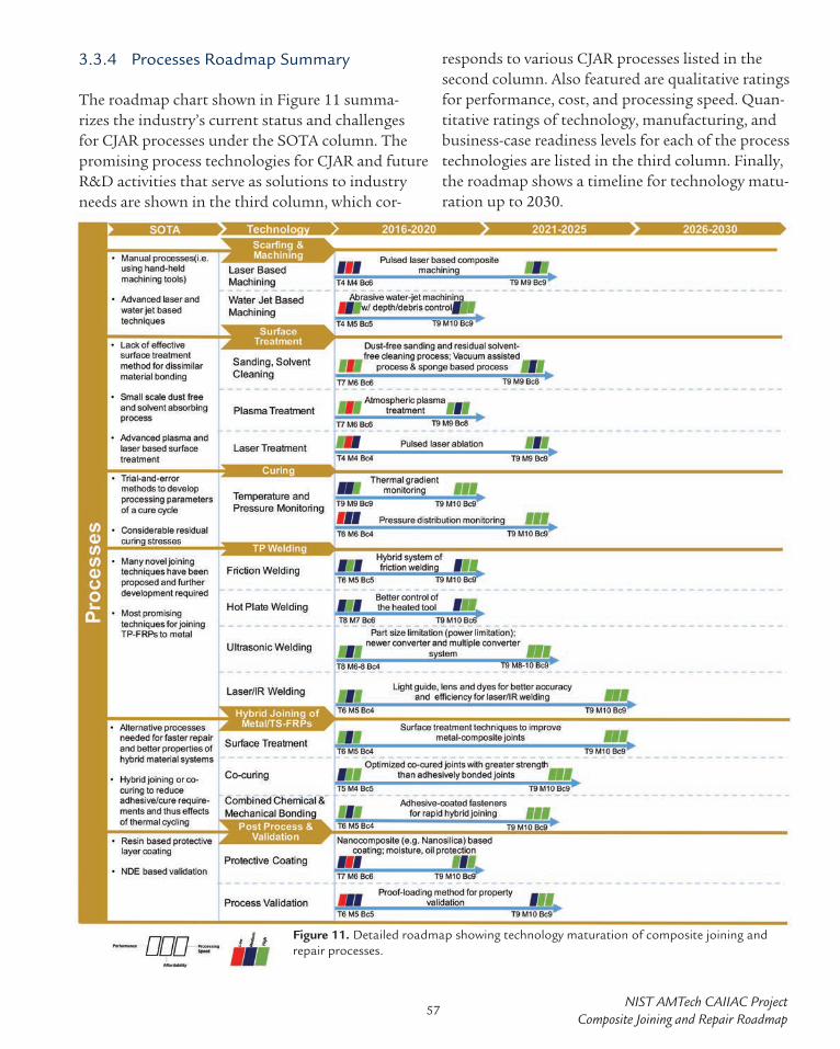
NIST AMTech CAIIAC ProjectComposite Joining and Repair Roadmap
3.3.4 Processes Roadmap Summary
The roadmap chart shown in Figure 11 summa-rizes the industry’s current status and challenges for CJAR processes under the SOTA column. The promising process technologies for CJAR and future R&D activities that serve as solutions to industry needs are shown in the third column, which cor-
responds to various CJAR processes listed in the second column. Also featured are qualitative ratings for performance, cost, and processing speed. Quan-titative ratings of technology, manufacturing, and business-case readiness levels for each of the process technologies are listed in the third column. Finally, the roadmap shows a timeline for technology matu-ration up to 2030.
Figure 11. Detailed roadmap showing technology maturation of composite joining and repair processes.
57

3.4 Computational Tools
Computational models, property databases, design, and analysis tools for CJAR are highly desirable, but are not prevalent in the industry. Most of the repair-specific design/modeling tools are pro-prietary and semi-empirically linked to specific proprietary processes and design details. Currently, most of composite repair work that is done is based on experience with some basic inspection. Model-ing/simulation tools are rarely used to help guide the repair technicians’ decisions for choice of NDI techniques, repair materials, repair design, or repair processes that would be most efficient for a given damage scenario.
3.4.1 State-of-the-Art of Computational Tools for Composite Joining and Repair
Composite design tools are evolving for use in en-suring the safety of adhesively bonded flight critical structures. Most common computer aided engi-neering programs such as ANSYS, ABAQUS, Pro engineer and Solid Works currently sell composite design features to supplement their finite element analysis engines. These tools are a good start, but specialty software for composite joining and repair is immature and needs more real-world valida-tion. Specialty software companies such as Altair have developed laminate on laminate mechanical analysis tools. However, a lack of suitable material models and failure criteria has resulted in a ten-dency to “over-design” composite structures [31]. Safety considerations often require that adhesively bonded structures, particularly those employed in primary load-bearing applications, include me-chanical fasteners as an additional safety precau-tion, resulting in heavier and costlier components. The development of reliable design and predictive methodologies can be expected to result in the more efficient use of composites and adhesives.
Structural joints represent a great challenge in the design of composite structures due to the inherent discontinuities in the geometry of the structure
and/or material properties that introduce high local stress concentrations. The design of structur-al joints requires analyses of stresses and strains under loading conditions and the ability to predict probable points of failure. Two basic mathematical approaches for analyses of adhesively bonded joints include closed-form analysis (analytical methods) and numerical methods (i.e. finite element anal-yses) [31]. Analysis in the literature covers a wide variety of joint configurations, including single-lap, double-lap, butt, scarf, stepped-lap, strap, corner, butt strap, stepped-scarf, T-shaped, L-shaped, doubler-doubler, tubular lap, etc. Step-by-step procedures for the preliminary design of compos-ite adhesive joints are available for use in hot/wet service environments under static and cyclic loads. Composite design tools can be used to design joints with minimal stress concentrations. Further, simu-lation tools can be used to predict whether the fail-ure will first occur in the composite laminates or in the adhesive. According, to the standard ASTM D5573, there are seven typical characterized modes of failure for adhesively bonded laminates: adhesive failure, cohesive failure, thin-layer cohesive failure, fiber-tear failure, light-fiber-tear failure, stock-break failure, and mixed failure. Primary failure modes for composite sandwich structures are buckling, local delamination, and fatigue/fracture. Although these failure modes are well characterized, the failure prediction of composite bonded joints is still difficult because the failure strength and mode differ for various bonding methods and parameters (e.g. amount of surface contamination).
Composite failure simulation with RADIOSS in case of a bird strike. (Source: Altair)
58

NIST AMTech CAIIAC ProjectComposite Joining and Repair Roadmap
Integrated Computational Materials Engineer-ing (ICME) is: (a) a method to engineer and cus-tomize material design and characteristics at the fundamental molecular levels; and (b) a method to model and understand—starting from the funda-mental molecular levels—how a (e.g. composite) material system evolves in a manufacturing process by modeling the fully coupled mechanical-chem-ical-thermal effects. ICME is currently not used on a day-to-day basis for composites in aerospace and automotive industries because it is still in the research phase. Early and important work that was focused on the fundamentals of ICME as they pertain to the manufacturing/design of composites in the automotive industry was started almost 15 years ago and continue to be developed [47, 48]. However, robust and predictive models for damage mechanisms in different composite structures and under various loading conditions are still sporadic and widely unavailable. The existence of accurate and predictive materials models appears to be the greatest challenge. Recognizing such a need the OEMs have made significant efforts towards the development of improved modeling techniques by building a foundation based on ICME for poly-meric composites. This is a paradigm shift that requires further developments in fully coupled mechanical-chemical-thermal understanding of the fiber-matrix-additives behavior of composites, as well as the manufacturing and repair of compos-ites. Current ICME-like approaches can be found in very few computational tools that model limited aspects of injection-molding processes of short fiber composites; however such tools hardly yield the necessary material-damage models of the man-ufactured composite that can be used to predict the sought after nonlinear structural response includ-ing damage and fracture.
3.4.2 Challenges and Emerging Solutions for Computational Tools
A significant need exists for new or improved com-putational tools to be used for both the design of composite structures and structural repair, as well
as for the analysis and prediction of their material and structural properties following damage events or repairs (see Table 10 on page 62).
Standardized composite structural design can be defined as generating confidence in the model and enforcing consistent practices. Standards for composites and their applications are unique and are proprietary to each organization. Therefore, universal standardized composite design is unre-alistic; materials, structure and application have to be considered for each specific case. Defining design guidelines and best practices would be more effective.
Databases for composite structural design most-ly exist in the aerospace industry. But, as the data is proprietary, most of the aerospace companies have their own database and do not trust the data coming from others. The barriers for developing a composite design database stem from IP issues and the lack of funding for testing. As an example, several million coupons were tested to get a materi-al and structural property database for the Boeing 787. The current “building block” approach in the aerospace industry requires significant effort and cost due to rigorous testing of every design step resulting in overly conservative, low-risk designs, that are generally safe and acceptable. An accurate strength prediction of the adhesively bonded joints is essential to decrease the amount of expensive testing at the design stage [31].
Composite materials allow for the novel capability to tailor the design to better adjust for where the highest loads are concentrated due to their aniso-tropic properties, which affords unique design opportunities such as controlling fiber orientation. However, the current “building block” approach and low-risk design strategy of the aerospace in-dustry offers very limited flexibility and, therefore, hinders the exploitation of unique features that could be made possible with composite materials via use of modeling/simulation design tools.
59

Integrated Computational Materials Engineer-ing: The major barrier for developing effective ICME tools is typically the lack of broad under-standing of all the underlying physics and chem-ical phenomena involved in the material being modeled. In many respects ICME as an area of research is still at relative infancy, and at the level of asking the fundamental questions. As ICME techniques evolve and emerge, a significant barrier to widespread use may be intellectual property (IP). Currently, there is a lack of cross industry collabo-ration as companies do not want to share their IP. In addition, new practical challenges will emerge such as whether standardized ICME methods exhibit high levels of confidence, and are such lev-els of confidence broad enough to span different designs, materials, and performance requirements. . Further, ICME for composites would generate a tremendous amount of data due to a large num-ber of simulations and the need to analyze them quickly, in order both visualize and process the data effectively. For small companies, ICME soft-ware licensing is expensive and, therefore costly to run numerous simulations in parallel.
Intellectual Property: Although IP issues have been a common theme for many of the above challenges, this barrier can be overcome. Develop-ing consortia like CAIIAC to spur industry col-laboration on pre-competitive projects where IP is not a concern or is shared is a practical solution. One successful model of pre-competitive joint collaboration consortia that has been in existence for almost 30 years (since 1988) was developed by the US automotive industry and is still actively involved (USCAR—US Council for Automotive Research, USAMP—US Automotive Materials Partnership, ACC—Automotive Composites Con-sortium, …etc.). These are several umbrella orga-nizations and consortia with different names and agreements between the Detroit Big 3 (FCA, Ford, GM), and in various activities they are partially funded by the US-DoE. These consortia have a streamlined IP process and joint-development
agreements that are focused on co-developing industry solutions to some of the very technical-ly challenging problems commonly faced by the OEMs, that are considered high-risk, advanced, and pre-competitive research.
Lack of Simulation and Prediction Tools for Damage Assessment and Failure: In general, the industry is concerned that the geometric mod-eling and visualization tools have become much more advanced faster and earlier than the simula-tion and predictive tools. Presently, the latter still lags and this has resulted in stagnation in the abil-ity to robustly and accurately model composites’ damage due to impact (crash), environmental fac-tors (heat, icing, erosion, aging), or deficiencies in manufacturing/repair processes over the last few decades. Development of these tools is important, for example to predict crack growth following the onset of microcracking and subsequent aging that could potentially lead to catastrophic failures. Due to the anisotropic properties of composites, it has been observed that crack propagation can occur in all three-dimensions and at different rates in each direction. Modeling of this phenom-enon is critical to help predict and prevent failures due to severe crack propagation in aged composite aircraft. Further, an accurate composite bonded joint analysis method is needed that can predict failure in the adhesive, at the adhesive-adherend interface, and within the surface plies of the lam-inate itself, and must also account for non-linear material behavior [31].
There are several factors that hinder the devel-opment of effective simulation and prediction tools for damage assessment and failure. First, it is well known that there are multiple modes of damage for composite materials and many failure modes at many different length scales, such as at the sub-ply, ply, laminate (e.g. delamination), and component levels (e.g. buckling, core-crush-ing). It is difficult to link physical models that exist at various length scales in a systematic and
60

NIST AMTech CAIIAC ProjectComposite Joining and Repair Roadmap
integrative fashion, particularly in doing so si-multaneously to account for prediction of time to failure. Secondly, all models rely on assumptions and accompanying experimental data that are used to define boundaries of applicability. Translating the data gathered from coupon testing into real-life structural damage scenarios and incorporating probabilistic aspects are especially challenging. Fi-nally, unlike metals, there are still many unknowns due to the limited understanding we currently have of composite materials. This results in a need for more basic research. Overall a lack of reliable fail-ure criteria still exists, limiting a more widespread application of adhesively bonded joints in principal load-bearing structural applications [31].
An emerging solution to effective damage model-ing in recent years has been the progressive damage modeling approach. This approach enables the complete response of structures up to the final point of failure to be modeled in a single analysis without the need for additional post-processing of finite-element analysis results. Progressive damage modeling uses either a local or continuum ap-proach. For the local (i.e. cohesive zone modeling) approach, the damage is confined to zero volume lines and surfaces in two and three-dimensions. For the continuum approach, the damage is modeled over a finite region with a predefined crack path. Progressive damage models are quite promising since important aspects of joint behavior can be modeled successfully [31].
Computational Modeling to Reduce the Time and Cost of Composite Certification and Qual-ification: New materials qualification costs are high and have to be covered by companies. Every change in the manufacturing or repair process requires re-qualification. Many manufacturing and repair improvements are not available for industry because of the qualification cost. Computational methods can reduce the cost to obtain necessary data. They have decreased the cost of certification. However, this depends on the industry. In the au-tomotive industry, data is acquired through simu-
lation and only final tests are done for regulation. While in the aerospace industry, tests dominate in the certification process. Given these examples, extending computational tools to discovery and development is much easier than obtaining certifi-cation. The validity of the model does not need to be as robust. More uncertainties are acceptable as there are lower risks. Further, modeling can be used to pinpoint test areas of higher concern, minimiz-ing the number and costs of subsequent structural tests.
AR Tools: Although maintenance errors are a recognized threat to aviation safety, there are few simulation and computer-based tools for manag-ing human factor issues. Augmented reality (AR) enhances user perception by superimposing addi-tional virtual content to real world environments in real time. Prototypes consist of a tracked head worn display to augment a technician’s natural view with text, labels, arrows, audio, animated sequences, video, etc., designed to facilitate task comprehen-sion, localization, and execution [41]. It is generally accepted that AR applied to maintenance can:
» Reduce the time and increase the effective-ness of training programs for CJAR by auto-matically and optimally guiding and tracking the training process steps
» Reduce the time required to locate or proper-ly orient to repair tasks within a maintenance sequence
» Reduce the time needed and human errors when performing repair tasks by acting as an intelligent assistant and providing virtual instructions.
» Reduce head and neck movements during a repair
Navigating and performing maintenance and repair procedures imposes significant physical requirements on repair technicians. For each task within a larger procedure the technician must first move their body, neck, and head to locate and ori-ent to the task. Next, they must perform additional physical movements to execute the task. Assistance
61

Table 10: Challenges and Emerging/Potential Solutions for Computational Tools
Challenges/Needs Emerging/Potential Solutions » Address IP issues and a lack of industry collabora-
tion » Develop new consortia (e.g. CAIIAC) that are based
on successful and long-standing model organiza-tions such as USCAR—US Council for Automotive Research, USAMP—US Automotive Materials Partnership, ACC—Automotive Composites Con-sortium, etc. to spur industry collaboration on pre-competitive projects where IP is not a concern or is shared
» Utilize third party providers (e.g. Altair) who pro-vide customizable computational software plat-forms to all customers including competitors
» Address variability in processing/anisotropy in CFRPs used for joining and repair
» Employ process specific modeling to reduce vari-ability
» Gain access to missing OEM original design re-quirements more easily when designing a repair
» Develop a computational tool that enables match-ing of OEM design allowables to a repair design, enabling better decisions by a technician
» Develop or advance existing tools for innovative composite materials development solutions
» Apply tools that enable computational develop-ment of new materials (MD simulation, ICME, etc.) to minimize the development period needed to create new products
» Reduce labor, cost, and time needed for certifica-tion/qualification testing
» Perform modeling to reduce the number of physical experiments needed for certification
» Develop repair-specific design tools » Develop design charts based on linking historical damage scenarios with best repair methods
» Use design charts as algorithms to develop field simulation tools; a simplified on-site design tool for field engineers
» Increase development of standardized databases or use of databases to improve CJAR
» Identify of non-impact failure modes of compos-ites (microcracking, moisture ingress, heat or icing damage, lightning strike, etc.) through data mining of FAA database on service failure
using AR enables optimization of these physical movements and can save time and energy. Those savings become significant when considering the dozens of potentially unfamiliar tasks distributed across a large complex system that are carried out each day by each technician. Further, AR can also save time and reduce mental workload by assisting the technician with cognitive requirements im-posed by maintenance and repair procedures [41]. However, many challenges exist that seem to hinder the effective implementation of AR in the industry, such as cumbersome hardware, the need to put
markers on the aircraft, the need to quickly create digital content that is customized to the repair en-vironment, and the reliability of object recognition that can be impaired by lighting variations. Future AR systems must overcome these limitations with improved efficiency by providing markerless track-ing via markerless camera pose estimation, efficient authoring procedures, hardware components with minimal weight and cost, and 3D animation overlap on several similar composite aircraft and in different lighting conditions [49].
62

NIST AMTech CAIIAC ProjectComposite Joining and Repair Roadmap
Table 10: Challenges and Emerging/Potential Solutions for Computational Tools
Challenges/Needs Emerging/Potential Solutions » Increase the quantity, quality (accuracy), and use of
simulation and predictive tools• Address issues with Big Data, databases, and
data sharing
» Accelerate efforts to develop damage assessment models to simulate/predict failure modes at multi-ple length scales
» Develop accurate inputs/assumptions for simula-tions
» Integrate SHM sensors and damage assessment software to develop a damage recognition system
» Develop tools not just for damage recognition or diagnosis, but for prediction of damage growth (e.g. crack propagation) and potential failures
» Utilize Internet of things (IoT) approach to deal with data and database sharing
» Increase fundamental research and in-situ process monitoring to reveal unknown properties
» Develop computational tools for improved inter-pretation of NDI results
» Develop simulations for composite NDI tools (e.g. stress wave analysis for laser bond inspection) to better understand and interpret NDI results
» Provide real time image analysis based on NDI inputs for effective NDE
» Increase utilization of new computational tools that can improve communication, guidance, and data sharing for more efficient repair and mainte-nance in the field
» Use AR tools to guide technicians with virtual in-structions during the repair process and easily track locations of damage for future repairs
» Utilize mobile devices and an IoT approach for sharing data or communication with experts or re-pair equipment to better inform and prepare repair technicians
» Use high performance and cloud based computing for enhanced computational processing power/speed, data storage and access
» Address restricted access to model, structural, or material property data including environmental effects
» Develop electronic SRMs for mobile devices » Enable OEMs to provide password encrypted or
paid subscription based access to databases or aircraft designs
» Employ virtual methods for preventing airlines from copying or screenshotting proprietary info., while allowing them to use the needed data
63

3.4.3 Computational Tools Roadmap Summary
The roadmap chart shown in Figure 12 summa-rizes our findings of the industry’s current status and needs/challenges for computational tools used for CJAR under the SOTA column. The promising computational methods and future R&D activi-ties that serve as solutions to industry needs are
shown in the third column, which correspond to various modeling tools listed in the second col-umn. The chart also features qualitative ratings for performance, cost, and computation speed; and quantitative ratings of technology, manufactur-ing, and business-case readiness levels for each of the computational technologies listed in the third column. Finally, the roadmap shows a timeline for technology maturation until 2030.
Figure 12. Detailed roadmap showing technology maturation of various NDI techniques for composite structures.
3.5 Automation
3.5.1 State-of-the-Art of Composite Repair Process Automation
Automation is critical to both the automotive and aerospace industry to reduce cycle time and cost of high volume production. Automation has been widely adopted in the manufacturing of higher-vol-ume commercial aircraft (e.g. Boeing 737 and 777) with a major goal of speeding deliveries and reduc-
ing order backlogs. Some examples include high precision robotic drilling and riveting holes on airframes, automated tape laying (ATL), automated or advanced fiber placement (AFP), painting, coat-ing, sealing, trimming of composite components, automated guide vehicles for transport of tooling, and machining aircraft engine turbine blades [50]. In contrast, aircraft repairs are primarily done by hand. It is envisioned that some automation technologies for aircraft production in the aero-space industry could be transferred to the MRO for
64

NIST AMTech CAIIAC ProjectComposite Joining and Repair Roadmap
automation of composite joining and repair. The type of automation implemented for repair highly depends on the application field. The automotive industry is looking for automation technologies that would enable composite joining and hybrid joining to be done on the assembly line, at the typical automotive production rates. The aerospace industry is looking to improve composite repair practices and automation could be one option.
Considering the increased usage of composites in both primary and secondary structural applica-tions, and that safety, quality, time, and cost are the key issues in composite repair, it is likely that automation will become a major industry require-ment for robust and reliable composite joining and repair. Structural repairs with automated processes help reduce aircraft downtime and consequently become cost effective. Although fully automated bonded composite repairs are a long-term goal made difficult by the inherent variability in aircraft structural damage and repair scenarios, automat-ing key elements involved in bonded repairs such as damage assessment, material removal, surface preparation, and repair patch manufacturing in the near-term could significantly minimize processing inconsistencies [51]. Given that safety is involved, human review and inspection of automated repairs is expected. This is because the cost of product liability litigation in the case of an accident would supersede any benefit of eliminating human inter-action.
A variety of SOTA methods that may be used to automate composite repair are being evaluated. Advanced NDI techniques such as laser ultra-sonic scanning, pulse thermography, and digi-tal shearography could offer opportunities for non-contact, fast, automated damage assessment. Non-conventional machining technologies such as pulse laser ablation and abrasive waterjet milling could allow improved automated machining for material removal, and also improve dimensional accuracy. Further, surface treatment techniques such as pulse laser and atmospheric plasma pro-
cesses could be automated for consistent, uniform surface properties. In addition, in-situ spectroscopy probes (e.g. Fourier Transform Infrared and Ra-man Spectroscopy), when combined with surface treatment techniques, could provide an integrated and quantitative assessment of surface properties to achieve consistent interface bond strengths. The feasibility of automated repair patch design and manufacturing using the AFP method are being evaluated [52]. Finally, integrated analysis and de-sign software tools can be developed to accurately automate damage assessment using machine vision algorithms, or automate prediction of the effects of machining, curing, material, and geometrical fac-tors involved in bonded repairs based on advanced numerical modeling techniques [23]. 3.5.2 Challenges and Emerging Solutions for Repair Process Automation
Advancing automated repair technologies is gain-ing momentum with the primary goals of reducing repair time, the cost of labor, the risk of human error, and the risk of accidents or injury. The bene-fits of automated processes for repairs of composite aerostructures are:
» Increased repeatability and reliability: automated processes will reduce variability induced by operators.
» Decreased cost: automated equipment can reduce cycle times to achieve increased in-service time and reduce workforce cost.
Although one may envision that automating repair processes could improve repeatability, some repair technicians believe that repairs cannot be auto-mated. This is because each damage scenario and, thus repair process, is unique. Some believe that for a process to be automated it needs to already be a repeatable process with a common set of known steps; whereas a composite structural repair requires a custom job. However, just because a pro-cess is customized to produce a unique specimen doesn’t mean it can’t also be automated. If that
65

were the case, then 3D printing used for custom manufacturing would not exist. Thus, it should be possible for automated processes to perform unique repairs that are best suited for the damage scenario while reducing manual labor and repair cost. Further, even when the entire repair process can’t be automated it may be helpful enough for just some of the process procedures to be auto-mated. Challenges for repair automation certain-ly exist, but can be overcome as suggested in Table 11 on page 67.
Automation for damage assessment is becoming more popular and can be done by a variety of methods. For example, currently during visual in-spection, damage areas are indicated and tracked by having technicians literally place stickers on af-fected locations of the aircraft. In the future, rapid wide area visual inspection by camera systems using machine vision algorithms will indicate po-tential damage areas. Augmented reality (AR) is a key tracking method that could be integrated with visual inspection systems for automated location tracking of surface and even underlying damage. Using a technology similar to Google Glass or Microsoft HoloLens, the repair technician could then quickly locate damage areas and even “see” a rendering of underlying damage or nearby com-plex contour structures that will better prepare the technician to make the appropriate repairs. These technologies would allow damage assess-ment and tracking digitally without touching the aircraft. However, the AR capability could only be realized by uploading the aircraft structural designs into MRO user databases, which requires permission of the OEMs. In addition, this data would include essential information that could be used to program robots for robotic repair opera-tions. Other NDI techniques besides visual inspec-tion, such as Ultrasonic Testing (as discussed in chapter 2), can be automated for quick and useful damage assessments. Airbus has demonstrated a specialized UT instrument called a “Line Tool,” that can provide a straightforward “go” or “no-go” decision for airline maintenance personnel in
the event of an impact to a composite component. This tool can rapidly detect delamination in a composite fuselage, reducing the inspection time from one hour to two minutes and without the need of an expert technician to do the measure-ment.
In addition to damage assessment, AR could be used on the manufacturing factory floor and in repair shops to provide virtual and visualized step-by-step instructions for composite joining and repairs. An electronic version of the SRM could be integrated with AR technology to make sure the instructions are compliant with federal regula-tions. A unique software could also be developed to help technicians with decision-making regard-ing the choice of repair design, materials, and processes with built-in predictions for structural repair performance.
One of the chief obstacles in the repair environ-ment is logistics and, fortunately, there are new automated location tracking technologies to help streamline these issues. It’s not only the repair labor that costs, but location tracking of MRO personnel, equipment/tools, repair materials, etc. can also add to the time and costs of repairs. For example, on the flight line, equipment and processes are strictly controlled to guard against potential fire hazards created by the presence of fueled aircraft. A properly executed in-situ repair requires far more advanced planning to ensure availability of repair materials, with knowledge of the spare part inventory and equipment locations.
Once deployed for the repair, you can’t afford wasted time for resupply. CribMaster is a compa-ny (acquired by Stanley Black & Decker in 2010) that provides solutions to these types of logistics issues through the use of passive radio-frequency identification (RFID) tags to improve asset man-agement of tools and equipment. As an example, CribMaster implemented their solution by setting up a passive RFID network within an Airbus MRO Center. This technology has delivered real time an-
66

NIST AMTech CAIIAC ProjectComposite Joining and Repair Roadmap
swers as to “who, what, when, and where” with re-spect to tools, equipment and even personnel who are tagged. The technology helps solve real-time issues in the MRO facility by finding lost tools or portable equipment, notifying the MRO managers of parts being picked up and where they are going, alerting them if a part is being delivered to the wrong warehouse, showing them the location of a part inside the warehouse, etc. Further, human error is also eliminated by replacing manual inven-tory forms (paper or spreadsheets). This real-time tracking software can be further integrated with Enterprise Resource Planning software, as well as other software systems, to run data analytics and provide deliverables like key performance indica-tors or lead time analysis and alarms.
BCT Steuerungs-und DV-Système GmbH, a Ger-man specialty manufacturing equipment vendor, has developed a software solution for automated composite repair preparation by scarfing and has integrated additional process steps such as surface activation by atmospheric pressure plasma. The objective is to reduce human influence and increase controllability of the process. A fully automated adaptive milling process for scarfing was demon-strated, showing increases in precision and greatly reduced process times. Different scarfing geome-tries have been implemented for specific customer requirements. To permit fully automated adaptive machining, precise knowledge of the part is re-quired. Hence the component is scanned and the acquired geometrical data is used as basis for an individually adapted machining process.
Table 11: Challenges and Emerging/Potential Solutions for Automation
Challenges/Needs Emerging/Potential Solutions » Develop new equipment or tools to enable auto-
mated repair processes that reduce repair time due to tedious or intensive manual labor processes, hu-man errors, and improves performance of repaired structures
» Employ high speed machining (e.g. laser or water-jet) of scarf surfaces
» Apply software solutions (BCT GmbH) for auto-mated scarf repair that includes part scanning for geometrical damage assessment, adaptive milling process for scarfing, and atmospheric pressure plas-ma surface preparation
» Combine robotics with AR platforms » Automate the wet layup process » Embed sensors for gap sensing, strain sensing, etc.
during processing » Automate evaluation of gaps in the bondline for
bonded repair » Develop an in-situ technique for bondline surface
mapping to eliminate the need for evaluating voids/porosity after repairs; could save several hours (e.g. 4 hours) in the joining process
» Automate toolpath generation and decision-mak-ing based on NDI data
» Automate damage assessment and defect location tracking• Reduce time wasted during inspection in man-
ually searching for damage areas• Identify and track underlying damage or
damage in the vicinity of complex structural contours
» Employ rapid wide area scanning, machine vision algorithms/software, and AR that will play crucial roles in addressing this need
Automated scarf repair tool. (Source: BCT GmbH)
67

Table 11: Challenges and Emerging/Potential Solutions for Automation
Challenges/Needs Emerging/Potential Solutions » Enable repairs in areas that are hazardous or diffi-
cult to physically access » Employ remote controlled robotic repairs » Develop miniaturized robots that automatically
perform NDI or repair functions in hard to reach locations
» Use drones for NDI or repair of wind turbines and large aircraft
» Develop sensor/inspection software packages for drones/robotics to identify nature of composite defects/damages and determine if damage is repair-able (initial screening).
» Improve NDE package for drones/robotic arms » Automate non-contact laser inspections for in-situ
process monitoring (e.g. tape application, tape removal)
» Provide automated virtual instructions to improve training or on-the-job work flow for repair techni-cians
» Integrate AR interfaces, electronic SRMs, and unique decision-making software to address this need
» Use AR to identify underlying complex structures or contours that could complicate repairs
» Implement technology needed to enable robotic repairs
» Develop machine learning algorithms to improve robotic repair processes, i.e. capture the experi-enced-based practices and convert into an automat-ed process
» Integrate original designs, AR tools, metrology data into robots to improve robotic usage for automated scarfing, surface treatment, NDI, etc.
» Improve lack of understanding of composites by programmers of automated tooling
» Improve education and training for the entire work-force. See Section 3.6.2
» Develop automation standards » Develop automation standards to increase automa-tion efforts across the industry
» Couple automated NDE with NDI tools for rapid inspection results
» Develop software to automate data analysis process for NDI
» Justify the use of automation despite the associated higher costs
» Use case-studies and techno-economic models that demonstrate the ROI
3.5.3 Automation Roadmap Summary
The roadmap chart shown in Figure 13 summariz-es our findings of the industry’s current status and needs/challenges for automation used for CJAR un-der the SOTA column. The promising automation methods and future R&D activities that serve as solutions to industry needs are shown in the third column, which correspond to various automation
tools listed in the second column. The chart also features qualitative ratings for performance, safety, cost, and automation speed. Quantitative ratings of technology, manufacturing, and business-case read-iness levels for each of the automation technologies are listed in the third column. Finally, the roadmap shows a timeline for technology maturation until 2030.
68

NIST AMTech CAIIAC ProjectComposite Joining and Repair Roadmap
Figure 13. Detailed roadmap showing technology maturation for automation of composite joining and repair.
69

3.6 Workforce Training, Standards, and Regulatory Issues
3.6.1 Current Industry Status of Composite Repair Training
Composite repair is currently more of an art than a science so much so that finding qualified work-ers is a real issue. MRO companies have developed their own internal training programs and rely on the expertise and experience of their repair tech-nicians to mentor new teams. Training is basically done within companies with the expertise gathered during the years of repair implementation. Previ-ously most composite repairs have mostly been on secondary structures, but as repair activities shift to primary loaded and flight critical structures, the need for appropriate training and repair technician certifications becomes essential. Developing new composites training programs would help compa-nies find qualified workers and would likely create greater demand for standardization within the composite repairs practice.
The FAA developed the Composite Structural Engi-neering Technology (CSET) training that is offered through Wichita State University’s continuing ed-ucation department. CSET training is dedicated to standardizing original certification and providing a follow-up evaluation activity for air carriers oper-ating aircraft with a seating capacity of 10 or more passengers. The FAA’s CSET training program is a 14-week course consisting of 1 week of prerequisite study, 5 weeks of online study, 1 week of laborato-ry offering, 1 week of midterm break, and 6 weeks of online study. The top-level course objectives include: (1) Students will describe essential safety awareness issues associated with composite struc-tural engineering important to safe composite aircraft product applications. (2) Students will de-scribe engineering principles of composite airframe substantiation during all stages of aircraft product certification. The FAA also developed DER train-ing (Engineering Designee Recurrent Training) to bring aircraft/airline operators in the aviation
industry up to the same level of training. Training must be completed every two years.
There are other training options as well. Abaris Training, for example, is an international orga-nization that specializes in training for bonded composite structures. They offer 28 short duration (5 days) courses. Eight of these are specifically designed for engineers. They also offer customized courses, such as training sessions to FAA inspec-tors or courses on composite quality assurance and documentation for Boeing.
Another entity involved in composites R&D, edu-cation, and training is the National Institute for Aviation Research (NIAR) at Wichita State Univer-sity (WSU) funded by the FAA. NIAR has developed reports to compare repair designs to monitor vari-ability in repair processes. The FAA offers its CSET and Composite Maintenance Technology (CMT) courses at NIAR on WSU’s campus.
In addition to these major training organizations and forums mentioned above, some universities and technical colleges around the country offer composites repair training. One such institution in close vicinity to Georgia Tech and the CAIIAC headquarters is Middle Georgia State University (MGA), with significant composites training initia-tives. MGA’s School of Aviation includes a De-partment of Aviation Maintenance and Structural Technology that offers both degree and certificate options for Aircraft Structural Technology and Aviation Maintenance Technology programs. The MGA School of Aviation is an FAA-approved Part 147 maintenance school offering management and supervision by skilled faculty. 3.6.2 Challenges and Emerging Solutions for Composite Repair Training
As composites parts move into primary loaded structures, an urgent need for trained staff to per-form flight-critical repairs is needed. The issue of composite repairs is very different from one indus-
70

NIST AMTech CAIIAC ProjectComposite Joining and Repair Roadmap
try to the other and thus requires different levels of skills and accountability. A catastrophic failure on an aircraft composite fuselage won’t have the same impact as a broken wind turbine blade.
The aerospace industry tends to use what is known and might choose to repair composite structures with a traditional metal-type repair technique. Airworthiness and flight safety are the main drivers. The industry appears stagnant since there has not been much change in the traditional training meth-ods over the last couple of decades. However, there is a critical need for increased numbers of highly skilled and qualified technicians in composites re-pair and maintenance. This is because as more and more composite aircrafts are being used, mainte-nance and repair activities will increase drastically. In addition, due to the advent and increasing pref-erence for bonded over bolted repairs, technicians will need to have a greater variety of skills due to the added complexity of the repair processes. They need to be able to do much more than drill rivet holes and bolt fasteners. Most existing composite repair technicians have acquired their expertise after years of practice and professional training sessions. However, to rapidly increase the num-ber of qualified technicians, the availability and frequency of training sessions/programs offered must increase, while the cost of training needs to decrease. Decreasing the cost of training will be a huge challenge as equipment and tooling for composite repairs is improved and becomes more expensive. This is why there is very limited training currently available for NDI. Training for an NDI technique (other than common visual, tap, or ul-trasonic methods) is simply too expensive and too specific. It takes a large amount of time and money to obtain a Level 3 certification.
One major workforce challenge is the low numbers of students that are interested in pursuing aviation repair and maintenance as a career option. This is similar to the workforce development challenges that exist currently in the manufacturing sector with the limited number of students who desire to
become manufacturing engineers and technicians. Although there is a growing need for a skilled labor force to fill these positions, which can provide well compensated and thriving career paths, many students are either not aware of or have a limited and/or unfavorable perception of these job roles. Composite joining and repair inevitably involves hands-on labor and it is difficult to get newer gen-erations of students to do manual labor. Of course, reducing the amount of manual labor involved in composite repair through increased use of emerg-ing technology, particularly computational tools and automation, could alleviate the unfavorable perceptions and attract more interest. For example, at the university level, more courses on composites manufacturing and repair could be offered and eventually lead to the offering of advanced degree programs. Introduction of CAD and CNC machin-ing work may interest design-oriented students and those who prefer hands-on activities. The industry needs an emerging workforce with a greater knowl-edge of computer aided tools for design work, fabrication, assembly, and repair. More important-ly, significant efforts should be made to increase awareness of these careers earlier by developing programs to inform students at K-12 grade levels and provide them ways to get the skills needed for a career in a technical field. In addition, more needs to be done to create a better pathways from K-12 to higher education to careers in CJAR. Currently, the decision to choose between a technical college or a four-year university seems to put a wedge between skilled labor and higher education when both highly skilled and educated technicians/engineers are needed. Moreover, it may be incredibly difficult for a technical college to acquire/purchase related equipment, as they generally operate on smaller budgets than universities. If the aviation industry is truly seeking technical college students, it would make sense to sponsor or help fund Tech School CJAR programs, thus making them available and more appealing to potential students.
Current and future workforce numbers may greatly benefit from a single underexploited demographic.
71

The US military sees thousands of well trained and highly experienced aircraft maintenance technician veterans separate or retire from service each year. With a combination of previous experience, and the ability to apply the use of their GI Bill educational benefits towards civilian FAA certification pro-grams, such as an Airframe and Powerplant (A&P) license or other applicable fields, these veterans often make the ideal aircraft repair technician, as they are highly disciplined and experienced. While some of these aircraft maintenance veterans already pursue a parallel civilian path, proper recruiting, transition, and incentive programs could be de-veloped and utilized to effectively bolster both the quantity and quality of related workforce numbers.
Another important consideration that must be addressed soon is how the training needs to evolve. To become more advanced, the environment of the training becomes critical. A typical classroom is very different than having to make an on-aircraft repair in the field under unexpected or unknown conditions. To address this, training sessions that include the environmental aspects would help prepare technicians. For example, sessions could be offered where technicians perform repair tasks within an enclosed environment where tempera-ture, humidity, air flow, etc. are controlled to simulate unexpected field conditions. In addition, repair training needs to evolve by including rele-vant emerging technology in the training sessions. Portable robotic scarfing technology offers a good example. It uses a portable robotic arm that can be controlled remotely by the technician to remove damage, scarf, surface treat, and apply material coatings without overspray. Again, the introduc-tion of high tech equipment and access to hangar facilities and aircraft will increase the cost of train-ing. However, the ROI may be justified as repair process automation technology operated by trained technicians could eventually greatly reduce costs of high volume repairs.
3.6.3 Current Industry Status of Standards Used for Composite Joining and Repair
Professional societies and international trade associ-ations in the automotive, aerospace, and composite materials industries, such as the Society of Automo-tive Engineers (SAE), American Composites Manu-facturers Association (ACMA), and the International Air Transport Association (IATA), etc., play a major role for developing technical standards for composite structures. For example, SAE International provides a forum for companies, government agencies, research institutions and consultants to devise technical standards and recommended practices for the design, construction, and testing of motor vehicle compo-nents. SAE documents do not carry any legal force, but are in some cases referenced by the U.S. National Highway Traffic Safety Administration (NHTSA) or the Federal Aviation Administration (FAA) in their ve-hicle regulations for the United States. SAE publishes more than 1,600 and over 6,400 of technical stan-dards and recommended practices for the automotive and aerospace industries, respectively.
The charter of the ATA/IATA/SAE Commercial Aircraft Composite Repair Committee (CACRC) is to develop and improve maintenance, inspection and repair of commercial aircraft composite structure and components. The six active CACRC task groups are: Repair Materials, Repair Techniques, Analytical Design, Inspection, Training and Airline Inspection & Repair Conditions. The mission of the CACRC is to reduce the cost of maintaining composite structures through standardization of materials, technique and training. The executive committee consists primar-ily of six airline or MRO’s members and six OEM members. However other voluntary members of the CACRC include suppliers, users (airlines and OEMs), and liaisons (consultant, regulatory, etc.). Table 12 on page 73 summarizes the goals of the working task groups within the CACRC and shows examples of technical standards that have been published or are currently being developed according to the informa-tion on the SAE website at the time of this writing. (Please contact SAE for the most up-to-date stan-dards publications.)
72

NIST AMTech CAIIAC ProjectComposite Joining and Repair Roadmap
Table 12: Example Composite Repair Standards Developed by CACRC Task Groups*
Active Task Groups Selected Published Standards or Standards Under Development1. Repair Techniques(Current Chair – Francois Museux, Airbus)
Goal: Develop standard repair process documents from cur-rent best practices.
Published » ARP5319 Impregnation of Dry Fabric and Ply Lay-Up » ARP5143 Vacuum Bagging of Thermosetting Composite Repairs » AIR5431 Repair Tooling » ARP4916 Masking and Cleaning of Epoxy and Polyester Matrix Ther-
mosetting Composite Materials » ARP4977 Drying of Thermosetting Composite Materials » ARP5144 Heat Application for Thermosetting Resin Curing » ARP5256 Mixing Resins, Adhesives and Potting Compounds » ARP4991A Core Restoration of Thermosetting Composite Compo-
nents » AIR5367 Machining of Composite Materials, Components and Struc-
tures » ARP5144A Heat Application for Thermosetting Resin Curing
Work in Progress » ARP5701 Lay-up of Prepreg Composite Materials » ARP5143A Vacuum Bagging of Thermosetting Composite Repairs » ARP5256A Mixing Resins, Adhesives and Potting Compounds » AIR5702 Storage and Handling of Epoxy Thermosetting Composite
Materials
2. Analytical Design(Current Chair – Tim Harris,Boeing)
Goal: Develop a standard repair design and analysis document.
Work in Progress » Develop a guide of generally accepted stress analysis methods used for
the design and evaluation of composite repairs for approval submis-sion.
3. Repair Materials(Current Chair – Dr. Ana Rodriguez-Bellido, Airbus)
Goal: Develop repair material specifications in support of commercial airplane bonder repairs
Published » AMS 2980 Carbon Fiber Fabric and Epoxy Resin Wet Lay-Up Repair
Material 1 through 6 » AMS 3970 Carbon Fabric Prepreg Repair Material with a Non-Struc-
tural Fiberglass Parts 0 through 6 » AMS2980/5A Carbon Fiber Fabric and Epoxy Resin Wet Lay-Up Repair
Material Part 5 - Material Specification: Carbon Fiber Fabrics, Plain Weave, 193 g/m2, and Epoxy
» AMS2980/2B Technical Specification: Carbon Fiber Fabric and Epoxy Resin Wet Lay-Up Repair Material Part 2 - Qualification Program
» AMS2980/1B Technical Specification: Carbon Fiber Fabric and Epoxy Resin Wet Lay-Up Repair Material Part 1 - General Requirements
» AMS6885 Carbon Fiber Tape Repair Prepreg, 120°C (250 °F) Vacuum Curing
Work in Progress » AMS XXXX Glass Fiber Fabric Repair Prepreg, 120 °C (250 °F)
Vacuum Curing Parts 0 through 6 » AMS 2950 Paste Adhesive for Core Restoration Parts 0 through 2 » AMS XXXX Carbon Unidirectional Tape/Epoxy Prepreg Repair
Material
73

Table 12: Example Composite Repair Standards Developed by CACRC Task Groups*
Active Task Groups Selected Published Standards or Standards Under Development4. Inspection (CurrentChair – Dr. Dennis Roach, Sandia National Labs)
Goal: Develop composite NDT calibration standards, and con-duct inspection detection round robins in conjunction with Sandia National Labs
Published » ARP5089 Composite Repair NDT/NDI Handbook » ARP5605A Solid Composite Laminate NDI Reference Standards » ARP5606A Composite Honeycomb NDI Reference Standards
Work in Progress » NDI Assessment: Honeycomb Structures
• Experiments completed in 2009• DOT report in progress
» NDI Assessment: Solid Laminate Structures• Experiment development completed including protocols• Experiment implementation with airlines (conventional NDI) com-
pleted in 2012• Experiment implementation to assess advanced NDI methods is
underway » Composite Impact Study
• Relate damage threat & structural integrity to capabilities of NDI to detect hidden impact damage in laminates
» Composite Porosity• NDI quantification of various porosity levels• Structural response – fatigue, residual strength, strain limits
» Composite Heat, UV, and Fluid Ingress Damage• Relate array of NDI options with strength measurements
» Miscellaneous Ongoing and Planned Studies• Detection and quantification of weak bonds• Effect of porosity, repairs & other impediments on NDI• General assessment of advanced NDI for composites• As required to support main tasks & other task groups
5. Training (CurrentChair – Tim Harris, Boeing)
Goal: Develop standard curricula for non-NDT inspectors, techni-cians and engineers.
Published » AIR4844B Composites and Metal Bonding Glossary » AIR4938 Composite and Bonded Structure Technician/Specialist:
Training Document » AIR4938B Composite and Bonded Structure Technician/Specialist
Training Document » AIR5278 Composite and Bonded Structure Engineers: Training Docu-
ment » AIR5279 Composite and Bonded Structure Inspector: Training Docu-
ment » AIR5719 Teaching Points for an Awareness Class on “Critical Issues in
Composite Maintenance and Repair” » AIR6292 Guidelines for Repair Process Evaluation of Fiber Reinforced
Composite Bonded Structure » ARP6889 Commercial Aircraft Composite Repair Technician Certifica-
tion-Qualification Standard
74

NIST AMTech CAIIAC ProjectComposite Joining and Repair Roadmap
Table 12: Example Composite Repair Standards Developed by CACRC Task Groups*
Active Task Groups Selected Published Standards or Standards Under Development5. Training -- continued from previous page
Work in Progress » AIR4844C Composites and Metal Bonding Glossary » AIR4938A Composite and Bonded Structure Technician/ Specialist:
Training Document » AIR5278A Composite and Bonded Structure Engineers: Training Doc-
ument » AIR5279A Composite and Bonded Structure Inspector: Training Doc-
ument » AIR5719A Teaching Points for an Awareness Class on “Critical Issues
in Composite Maintenance and Repair”
6. Airworthiness(Current Chair – Todd Herrington, Delta Air Lines )
Goal: Develop documents that provide key characteristics for the overhaul of production components.
Published » AIR6291 Guidelines for Repair Process Evaluation of Aluminum Bond-
ed Structure
Currently Inactive Task Groups include Design, Life Cycle Mod-el, and Inspection and Repair Conditions
Published » AE-27 Design of Durable, Repairable, and Maintainable Aircraft Com-
posites » AIR5416 Maintenance Life Cycle Cost Model
Abaris training session for composite repair. (Source: Abaris Training)
* For additional information go to: https://www.sae.org/works/documentHome.do?comtID=TEAAMSCACRC
75

3.6.4 Challenges and Emerging Solutions for Standards Development/Implementation
The most significant concerns and challenges for CJAR in the aerospace industry relate to a lack of standardization of composite products, tooling, processes, training, materials, etc., and the related effects on airlines/MRO who can’t afford to effi-ciently apply so many different proprietary tech-nologies (e.g. perishable material storage, process quality development, training curriculum, etc.). The industry is in desperate need of a set of stan-dardized best practices for repair materials, pro-cesses, NDI, design tools, supply chain, training, etc. that go beyond current SRMs and are applica-ble for all OEM, MRO and supplier organizations. This type of standardization would allow for more effective and efficient industry operations for both manufacturing and repair segments. Today, if a repair is needed for a damaged struc-ture, the technician must first review the SRM. The CACRC has developed best techniques or best industry practices for repairs. However, standards need to be referenced in the SRM. The current SRM does not include standard CACRC repairs and thus are likely not being used by many repair technicians. The reason they are not referenced in the SRM is because the SRM is specific to a single OEM and associated aircraft designs. For example, for Boeing and Airbus SRMs, the methodology may be similar, however, specifics may be different because each airline has different materials, struc-tures, components, etc. The CACRC has already qualified several materials for repair, such as pre-pregs, out-of-autoclave, wet layup materials, and is continuing the business of making new standards. However, a future challenge for this organization will be maintaining and updating the standards on a regular basis. It is not clear if the CACRC is cur-rently big (few hundred members) or active enough to support these activities. Although the CACRC is leading efforts to provide standardized best practic-es for CJAR, this organization and similar entities are run by unpaid industry volunteers who may
only formally convene once or twice a year. Further their members have restrictions via their employers that would prevent full disclosure to one another (since many work for competing companies). As a result, the CACRC progress with creating standards is slow. For example, it took over 10 years to qual-ify a wet layup system (Huntsman 52AD). It was suggested by industry experts that if participation in these organizations were made mandatory with more frequent meetings, perhaps as an essential part of selected employee job responsibilities, the progress on these standardization efforts could be accelerated.
It is clear that more standardization is needed to improve the current state of the industry; however, part of the challenge will be not to overly standard-ize. Rather, it will be important to find the right balance of standardization such that technological innovation and healthy competition between busi-ness enterprises are not compromised or hindered. Repair tools and strategies are currently all devel-oped in-house for IP issues. People feel they have a competitive advantage when keeping the informa-tion proprietary. The objective would be to find the common data that can be shared amongst users and subsequently grown to address CJAR concerns over a variety of industrial sectors. The automotive sector might be more open because there are not as many proprietary issues.
Even if IP issues were resolved for composite repairs, it is difficult to have one method for all. The objective instead should be to minimize the variability of data and standardize how the engi-neer and technician could do the repair. Work is needed on developing examples and scenarios. The big question is how much or which information should be included in attempting to standardize the data? Considering the end user and categoriz-ing the information by end user type is critical if there will be any insurance that the correct users get the correct data. Large companies have the resources to gather and sort this kind of data. However, the MRO team would prefer not to have
76
NIST AMTech CAIIAC ProjectComposite Joining and Repair Roadmap
to rely on the OEM for repair data. Standardization of materials would make it easier, too, if only 10 to 15 materials would be kept in stock instead of the current practice of a few hundred. The standard-ization of materials is recommended by CACRC. Composite Materials Handbook-17 is a good start, but the time and expense it takes to qualify a par-ticular material combination, including layup and cure variations, greatly limits new material design information.
Another issue is that as composites usage and thus repairs are shifting toward primary structures, there is significant concern that the standards for composites repairs on secondary structures will be extended to primary structures, which would be highly problematic. Secondary structures tend to have emphasis on high stiffness as opposed to strength, which is needed for primary structures. Further, secondary structures exhibit low strain levels during flight such that failure due to long-term operation is not an issue. Primary structures are more susceptible to long-term degradation due to exposure to more frequent and higher strain lev-els acquired over many flights. Primary structures must be tested under long duration cyclic loading to evaluate damage thresholds and tolerances. The differences in materials, structural components, mechanical properties, mechanical loads applied, and damage induced on primary and secondary structures will result in the need for significant-ly different repair strategies and procedures that should be reflected in emerging standards.
Finally, it is difficult to train technicians on new composite structures when the OEMs provide limited information and training organizations, like Abaris, rely on industry insiders to obtain unofficial specs. This constantly leaves the oper-ators behind the learning curve. It is a “catch 22” scenario and some believe it will take one or more catastrophic failures resulting in loss of life to change it.
3.6.5 Current Industry Status for Regulation of Composite Repairs
In general, regulation tends to be overly conserva-tive due to the emphasis on safety and quality in the aerospace industry. The FAA does not regulate the method of compliance; it just provides the ex-pected end results. While the expectations outline the required parameters, the FAA leaves methodol-ogy up to the company. In composites, the number of plies, the resin system, the core, and about every-thing can be different so the FAA has little interest in being specific, but has great interest in harmo-nization of end use requirements and evaluations. Increased harmonization will result in standard-ization and the ability to pass knowledge on to the next generation of aircraft engineers and scientists. Harmonized approaches will also enhance aircraft safety and reduce the amount of “shop specific” required training.
3.6.6 Challenges and Emerging Solutions for Regulation of Composite Repairs
As new CJAR technology is developed and matures toward commercialization, a significant hurdle particularly for the aerospace industry will be regu-lator certification of the supplier, product, and pro-cess such that these solutions can be implemented to improve MRO operations.
Challenges of Qualifying Suppliers and Re-pair Environments: Feedstock for the composite process must be consistent from order to order over long periods of time. The basic materials must not change over time because of moisture, han-dling/transport, or exposure to solvents and other contaminants commonly found in an industrial setting. For composites, the qualification process is nearly the same as for metals, but composites are highly process-sensitive. Design approver holders complete thorough testing and validating because it is their name that appears in the end. In most cases, for design approval holders, changing material providers is very difficult because it is
77

process-centric. Furthermore, not all composites fabrication shops have consistent air quality, nor is there total control over surface contaminants. Each fabricator needs to be able to audit his sub-tier ma-terials suppliers to ensure a consistent product and then complete chemical and mechanical testing to validate product consistency. Reliable structures demand consistency in materials production and process implementation.
The Role of Standards in Regulator Certifica-tion of Emerging Technology: From the view-point of aerospace regulators, certification does not imply reliability, nor does the use of quality control metrics generated by industry themselves measure success in executing and monitoring their own processes. The FAA defines certification in terms of compliance with FAA regulations. The FAA cannot evaluate certification efficiency in technology lower than TRL level 6 because they don’t certify manu-facturing, structures or maintenance technology independent of a given aircraft product. Their only ability to make judgments on the maturity of new technology would be an assessment of a more glob-al industry acceptance. For example, the establish-ment and industry acceptance of public standards that they use in data packages for actual certifica-
tions, indicating consistent industry practices as accepted by different certification projects. Thus, it would be helpful for the CAIIAC consortium to as-sist other standards organizations in creating new industry-accepted standards because it provides goals that represent more than individual company accomplishments. For example, a patent doesn’t help global technology acceptance, while standards not only indicate technology maturity but also fa-cilitate technology transfer. Thus, development of new industry-wide standards offers a pathway for rapid certification and commercialization of new repair technology, including new repair equipment and processes. A major impediment to this vision, however, is that each OEM uses proprietary tech/specs and each related operator/company devel-ops its own solutions/dealings, leaving a major hurdle for growth and standardization, which promotes stagnation. This is the main reason why the CACRC exists and other emerging organiza-tions, like CAIIAC, are facilitating a consortium or domestic ecosystem of industry, government, and academic partners to collaborate and overcome these obstacles. Challenges and potential solutions related to all of the issues mentioned above, includ-ing training, standards, supply chain, and regulato-ry, are summarized in Table 13 below.
Table 13: Challenges and Emerging/Potential Solutions for Workforce Training, Standards, Supply Chain and Regulatory Issues
Challenges/Needs Emerging/Potential Solutions » Reduce complexity and accelerate the MRO supply
chain » Increase standardization of materials » Use standardized fiber property and size (universal
sizing) to alleviate supply chain complexity » Increase supplier networks for rapid distribution,
materials-on-demand, or just-in-time delivery » Qualify materials suppliers for precise or standard-
ized products » Provide identical items except in different quanti-
ties and package sizes for manufacturers and repair shops
» Buy and resell specifications needed for consistent products through their life cycle
» Use a subscription model for legacy materials and products
78

NIST AMTech CAIIAC ProjectComposite Joining and Repair Roadmap
Table 13: Challenges and Emerging/Potential Solutions for Workforce Training, Standards, Supply Chain and Regulatory Issues
Challenges/Needs Emerging/Potential Solutions » Increase development and adoption of active CJAR
standards » Keep momentum but accelerate the progress of the
CACRC by increasing frequency of meetings » Encourage company managers to select employee
participants in the CACRC and apply pressure to make CACRC membership and efforts mandatory as part of their job responsibilities
» Encourage emerging entities such as CAIIAC to assist standards organizations in accelerating the development of repair standards
» Insert newly developed CJAR standards into struc-tural repair manuals so they become more stan-dardized for all OEMs and airlines; this will require approval from multiple organizations
» Demonstrate business-case and ROI for CJAR stan-dardization to OEMs and regulators (FAA) using case-studies or techno-economic models
» Create new regulations to drive standardization » Maintain and update standards regularly (CACRC
and other standards organizations) to keep pace with innovation and technology development
» Develop a materials recycling standard » Develop standards specifying conditions for ship-
ping, handling, and storage of repair materials » Develop a maximum contaminant level standard
following surface treatment to ensure bond quality
» Recruit, train, and increase emerging workforce » Increase number and quality of professional training programs. Require mandatory composite training classes for all current composite repair employees.
» Increase awareness of careers in composite mainte-nance and repair starting early at k-12 levels.
» Develop clear pathways to navigate from k-12 levels into a career for composite repair engineers/techni-cians
» Create B.S. and higher level degree programs in composite manufacturing/repair engineering
» Evolve training efforts to include preparation for unexpected environmental conditions and use of advanced technology tools
» Develop a process for certifying and standardizing training; all repair technicians/engineers need to obtain training certificates that have industry-wide recognition, prior to practicing in the field
» Support higher training costs » Seek financial assistance from government entities at State and Federal levels who are interested in in-creasing employment and associated tax revenues.
79

3.6.7 Training, Standards, Supply Chain, and Regulatory Roadmap Summary
The roadmap chart shown in Figure 14 summa-rizes our findings of the industry’s current status and needs/challenges for training, standards, supply chain, and regulatory issues used for CJAR under the SOTA column. Suggested methods and
future activities that serve as solutions to industry needs are shown in the third column, which corre-sponds to standards, supply chain, workforce, and regulatory categories in the second column. The chart also features qualitative ratings for comple-tion level, affordability, and supply chain speed in the third column. Finally, the roadmap shows a timeline for maturation until 2030.
Figure 14. Detailed roadmap showing projected advances in workforce training, standards, supply chain, and regulatory issues for composite joining and repair.
80

NIST AMTech CAIIAC ProjectComposite Joining and Repair Roadmap
The CAIIAC team successfully developed the first technology roadmap focusing on composite joining and repair. Table 14 summarizes the findings by market driven priority. We have a wide array of com-mitted stakeholders, identified technical needs, and
4. Conclusions and CAIIAC Future Outlook
industry critical research development and demon-stration projects (see Section 4.1) to be addressed by the future CAIIAC consortium. CAIIAC is ready to work with industry and other partners to solve criti-cal problems as soon as the projects are funded.
Roadmap Category
SOTA Future Requirements by Market Driven Priority Short
TermMid Term
Long Term
Materials » Cycle Time » Bonding Strength
» Lack of Standardized Material Properties Databases
» Inadequate Lifecycle Analysis Data, Recycling, and Repair Options
» Slow Curing Speed
» Fast Curing
» High Bonding Strength
Processes » Scalability » Consistency » Quality
» Limited Processing Area and Rates » High Temperature, Vacuum Pres-
sure Required
» Rapid Repair Time, Automated Processes
» Large Processing Areas
» Atmospheric Processes
NDI/NDE » Speed of Inspection » Probability of De-
tection » Accuracy
» Slow Inspection Rates » Lack of Detectability: Kissing Bond
and Aging » High Accuracy for Inspection of
Voids and Delamination » Medium Accuracy for Inspection
of Crack and Honeycomb Damage
» Detectability of Kissing Bond and Mate-rial Aging
» High Accuracy for Inspection of Crack and Honeycomb Damage (< 0.1 mm Resolution)
» Fast Inspection Over Large Areas; 10 Times Faster than Current Inspection Methods
Computational Tools » Computer Aided
Repair and Training » Modeling for Repair
Analysis and Design
» Inefficient Human-Machine Inter-action Interface
» Lack of Verified Repair-Specific Computational Models
» Process Modeling for Repair Analysis and Design
» In-Service Modeling for Strength and Durability Analysis
» AR Software/Hardware Development for Work Assistance
Automation » Performance » Affordability
» Labor Intensive Processes Done by Hand (High Cost and Time)
» Huge Operator and Parameter Dependency in Repair Quality
» More Tools and Equipment Infra-structure Needed for CJAR
» Improved Control Software and Moni-toring Devices for Automated Curing
» Automated Positioning and Tracking Systems using AGVs, Laser Tracking, and AR
» Embedded Sensors for Real-Time Struc-tural Health Monitoring
Standards, Reg. Issues, Workforce Training, & Supply Chain » Completion Level
» High Volumes of Inventory Waste at Repair Shops (Most of Prepreg Stock Discarded After 6 Months)
» Lack of Industry-Wide Standards » Strong Industry Need for More
Highly Skilled Technicians
» Fast, Nationwide Distribution Network; Smaller Package Sizes for Repair Shops
» Certified, Adopted Standards for Repair Materials, NDI, Processes, Training, etc.
» Enhanced Training and Shop Floor Work Instructions using Augmented Reality
Table 14: Challenges and Emerging/Potential Solutions for Workforce Training, Standards, Supply Chain and Regulatory Issues
Roadmap Timeline
4
4
4
4 4
4
4
4 4 4
4 4
4 4
4 4
4 4
4 4
4 4
4
4 4
4 4
4 4
4
81

4.1 Demonstration Projects
In the final CAIIAC workshop held on March 29, 2016, subject-matter experts were asked to review and critique the draft roadmaps for each topical area, as well as suggest critical R&D demonstra-tion projects that could be addressed collective-ly and pre-competitively by future consortium members. Feedback from the workshop, including these industry critical R&D projects, was reviewed and vetted by the CAIIAC team. Below are the 12 demonstration projects identified by the team. In the near-future, these projects will be prioritized, potentially funded, and pursued collaboratively by selected consortium member organizations.
1. Standardized Database and Training for Repair Materials and Procedures: Currently repair methods and materials vary between OEMs, resulting in high costs to the operator. These costs are due to extensive technician training require-ments, the need to stock a range of repair materials, and the cost of disposing of expired materials. The development of a set of FAA approved standardized repair techniques and materials would potential-ly eliminate some of these costs. Research would identify the most common types of composite repairs performed by aircraft operators and develop a repair method that meets most OEM standards. Efforts would also be made to identify a shortlist of common materials that meets most OEM stan-dards. Researchers would generate a standardized repair manual (that applies to all or most OEMs, subject to FAA approval) and database of prop-erties for the materials and methods used in the repair manual. This list of standardized repairs would lead to a curriculum for a certified training program for the CJAR workforce.
2. Embedded Sensor Systems for Real-Time Process and Structural Health Monitoring: Research projects are needed to develop embedded cure monitoring systems that measure and trans-mit data on temperature and pressure distributions during out-of-autoclave (OOA) curing in order to
improve OOA tooling and optimize process param-eters for bonded repairs. These sensors may also be important for the detection of heat damage and for lifecycle health assessment during which multiple curing cycles and repairs may be needed on the same part. In addition, embedded bondline surface mapping may eliminate the need for evaluating voids and porosity and thereby save up to 4 hours in the joining process. Further, embedded systems for structural health monitoring consisting of embedded gap sensors, strain sensors, crack detec-tion devices, and electronics for data storage and transmission are also needed.
3. Advanced Methods for Nondestructive De-tection of Kissing Bonds and Quantification of Bond Strength: Currently, mechanical join-ing using fasteners dominates repairs of primary composite structures due to the inability to char-acterize bonding strength or check for insufficient bonding due to formation of weak or kissing bonds. Additional research is needed to investigate emerging methods for detecting kissing bonds and quantifying bond strength such as laser bond inspection, nonlinear ultrasound, and quantitative digital shearography techniques. Research should be performed to either improve these existing techniques or develop novel experimental methods. This research may also seek to integrate computa-tional modeling tools that can be used to predict the effectiveness or down-select prospective NDI technologies.
4. In-Situ NDI Techniques for Quality Con-trol of Surface Treatment Processes: Improper surface treatment of composite surfaces may be the leading cause for the formation of kissing bonds during manufacturing and repair. Research is need-ed to develop in-situ, or in-line, NDI techniques that can characterize the quality of surface treat-ment during the manufacturing or repair process. The research would develop a quantifiable surface treatment metric (i.e. a number 1-10) that assesses the quality of surface treatment (perhaps based on the amount of foreign particles/contaminants on
82

NIST AMTech CAIIAC ProjectComposite Joining and Repair Roadmap
the surface). This type of process monitoring would eventually use a feedback loop that can reduce vari-ability in the process and prevent the root causes of kissing/weak bonds before they occur.
5. 3D Printing for Rapid Tooling and Automat-ed Onsite Repairs: Currently repair shop opera-tors have to reverse engineer their own molds for mold surface repairs. The current method is very labor intensive and expensive. 3D scanning and printing of molds would allow faster and lower cost mold replication. Currently parts are repaired by hand and automated systems, but parts are first removed from the aircraft to perform repairs. 3D printing enables onsite repairs by mounting 3D printing systems on the aircraft and directly printing onto the repair surface. In the long-term 3D printing will replace automated fiber or tape placement, but currently 3D printed materials lack sufficient mechanical properties.
6. Simplified Computational Tools for CJAR Field Engineers and Technicians: The CJAR industry can greatly benefit from computational tools but currently they are expensive, time con-suming, plus they require significant expertise and training. This project seeks to develop simplified tools that can be used directly by field engineers or technicians with very little training. Examples of these tools include databases or design charts with well-defined inputs and outputs that are based on computational modeling results for common re-pair scenarios. The field engineer or technician can use these design charts to improve their decision making and confidence for making repairs.
7. Time Study on Composite Repair: Composite repair is a time consuming process. In order to un-derstand how to reduce the time spent on a repair, it is important to first understand how much time is spent on each process in the repair. This project would study several of the most common compos-ite repairs and quantify the amount of time spent on each step. Future research would seek to reduce
the most time intensive steps.
8. Identification of Non-Impact Failure Modes in Composites: The FAA maintains a database to track failure and damage of commercial aerospace parts. Data mining could be used to determine the number and types of non-impact related failure seen in composite parts. This data could be useful to determine areas of potential interest for future materials development research.
9. Remote Controlled Robotic Operations for CJAR: Prior to realizing fully automated robotic operations for CJAR, a preliminary step will be to demonstrate remote controlled operation of robots to reduce the amount of manual labor and labor time involved with challenging repair tasks. Researchers could demonstrate remote controlled operations such as scarfing, NDI, or ply cutting. Miniaturization of remote controlled robotics would also be of high importance for performing operations in small, difficult to reach, and/or dan-gerous spaces.
10. Development and Assessment of CJAR Techniques Involving Heterogeneous Materials: Prior to development of all or majority composite primary structures, there is a need to understand and improve processes for hybrid joining of dissim-ilar materials such as composites and metals that are currently being performed by major OEMs. Re-search is needed to develop and assess specific and/or standardized processes for joining dissimilar materials as they will differ from joining or repair performed on homogeneous structural materials. There is a need to understand the advantages and disadvantages of using dissimilar materials and what combinations are optimal.
11. Application of Augmented Reality and Digital Imaging Technologies in CJAR: As an emerging technology, augmented reality has been tested and used in various industry applications, such as product design/testing, education/training, marketing, etc. Other related digital imaging tech-
83

nologies also find similar applications. With their rapid advancement, these technologies are expected to be further developed and refined for the follow-ing CJAR related applications: (1) CJAR operations training, (2) identification of underlying or hard to reach components; (3) identification and tracking of defects (such as dents and small damages); and (4) automated remote inspection (such as automat-ed inspection of aircraft with drones).
12. Development of Data Analytics and Machine Learning Tools for CJAR: As composite materials design and manufacturing, sensing, and comput-ing technologies advance rapidly, more and more sensors and smart devices will be used in CJAR systems. These data-rich systems provide not only opportunities, but also complexity and challenges for monitoring and optimizing CJAR operations. Advanced data analytics and machining learning methods and tools that can automatically identify CJAR operation issues (such as materials and pro-cess defects), prognose failures, and optimize CJAR maintenance (e.g. condition-based maintenance) are highly desirable.
4.2 Consortium Model and Future Plans
Project funding will depend on the structure and by-laws of the consortium organization, which is currently being formulated and refined. It is known that the consortium will have a tiered membership structure, where the member tier determines fees and the weight of votes for participation in precompetitive demonstration projects. After publishing and distributing this report, the CAIIAC team will organize meetings with its partners to accom-plish several tasks: (1) Verify participants/partners who want to pay member dues and become official CAIIAC member organiza-tions; (2) Review demo projects to get mem-ber feedback and further down-select; (3) Vote on RD&D projects and submit member dues to fund those projects; and (4) Determine ways to solicit additional funds to support projects based on expected budgets. In the long-term as projects are underway, CAIIAC plans to develop shared facilities or joint labs for member access and hold recurrent annual meetings to choose/review pre-competitive projects and update roadmaps.
84
NIST AMTech CAIIAC ProjectComposite Joining and Repair Roadmap
5.1 Meta-roadmapping
In order to obtain empirical information on topical areas considered in this roadmap, we obtain pub-lication and patent records published up to 2014. A list of keywords related to the particular topical area is collected. Based on these keywords, a search strategy is defined. This search strategy is converted into a query, which is used to download the records from the databases. We utilized Web of ScienceTM Core Collection database (accessed through the Georgia Tech Library) to obtain the publication records and Derwent Innovations IndexSM (accessed through the Georgia Tech Library) to obtain the patent records.
After downloading the publication and patents records, we follow a systematic procedure to an-alyze the growth and developmental trend of the topical areas, one at a time. First, we import the publication records to the VantagePoint (www.theVantagePoint.com), a desktop text mining software. Information pertaining to various fields such as title, abstract, keywords plus, keywords (author’s), and publication year gets extracted from all the records. For a publication record, keywords plus is comprised of words and phrases extracted from titles of the cited articles (Quick Reference Card, Web of Science, http://wokinfo.com/media/pdf/qrc/wosqrc.pdf). The field, namely keywords (author’s), consists of keywords provided by the authors for an article. We employ VantagePoint’s Natural Language Processing (NLP) to extract nouns and phrases from the titles and abstract of the records. This generates two new fields namely title phrases and abstract phrases. We use a com-bination of the four fields – title phrases, abstract phrases, keywords plus, and keywords (author’s). The combined field gives us a list of keywords and phrases. In this list, we look for the desired topics related to the topical area and analyze the trend of their publication activity. Second, in the case
of patent records, we follow a similar procedure. We import the patent records to the VantagePoint where we extract fields such as title, abstract, and basic patent year. We apply VantagePoint’s NLP to the titles and abstracts of the patent records and generate a list of terms and phrases by combining these two fields. We extract the required topics from this list and study their development in terms of the number of patents over the time. Once we obtain the trends in the publication and patenting activities, we use this quantitative information in our roadmapping procedure. This methodology is shown in Figure A1.
5. Appendices
Figure A1. Methodology for publications and patents analysis.
Select topical area
Identify related keywords
Develop search strategy and define search query
PUBLICATION DATABASE
Web of Science TM Core Collection
Download publication records and import
them into VantagePoint
Extract title, abstract, keywords plus, keywords
(author’s), and publication year
PATENT DATABASE
Derwent Innovations Index SM
Download patent records and import
them into VantagePoint
Extract title, abstract, and basic patent year
Generate a list of keywords and phrases
Select desired topics and analyze their development in terms of number of publications and patents
85

Sample Data: We collected a list of keywords re-lated to the topical areas and developed the search strategies to download the publication and patent records from the databases. Table A1 shows sample
search strategies or queries and the corresponding number of publication records. Results from the search queries can easily be plotted as shown in Fig-ures A2 and A3, and used for subsequent analysis.
CategoryNumber of Publication
RecordsSubcategory + Search Query
1,870
Thermoset(TS=((composite* OR fiber reinforced polymer* OR fiber reinforced plastic* OR fibre reinforced polymer* OR fibre reinforced plastic*) AND thermoset* NOT nano* NOT bio* NOT medic* . . . AND LANGUAGE: (English) Index-es=SCI-EXPANDED, CPCI-S, CCR-EXPANDED, IC Timespan=1900-2015
4,252
Thermoplastic(TS=((composite* OR fiber reinforced polymer* OR fiber reinforced plastic* OR fibre reinforced polymer* OR fibre reinforced plastic*) AND thermoplas-tic* NOT nano* . . . AND LANGUAGE: (English) Indexes=SCI-EXPANDED, CPCI-S, CCR-EXPANDED, IC Timespan=1900-2015
3,475
Adhesive(TS=((composite* OR fiber reinforced polymer* OR fiber reinforced plastic* OR fibre reinforced polymer* OR fibre reinforced plastic*) AND adhesive* NOT nano* NOT bio* NOT medic* . . . AND LANGUAGE: (English) Index-es=SCI-EXPANDED, CPCI-S, CCR-EXPANDED, IC Timespan=1900-2015
1,037
Prepreg(TS=((composite* OR fiber reinforced polymer* OR fiber reinforced plastic* OR fibre reinforced polymer* OR fibre reinforced plastic*) AND prepreg* NOT nano* NOT bio* . . . AND LANGUAGE: (English) Indexes=SCI-EX-PANDED, CPCI-S, CCR-EXPANDED, IC Timespan=1900-2015
Table A1: Sample Data Mining Search Queries
Figure A2. Annual publications for composite materials: thermoplastics, thermosets, prepregs and adhesives.
Sample Results
Materials
86

NIST AMTech CAIIAC ProjectComposite Joining and Repair Roadmap
Figure A3. Annual registrations of patents for composite materials: thermoplastics, thermosets, prepregs and adhesives.
Meta-roadmapping is a powerful technique used to support our roadmapping process, and a unique aspect of our methodology compared to other roadmapping efforts. Meta-roadmapping is a powerful tool because it can both assist with the initial development of roadmaps, as well as be used to validate the accuracy of existing or draft road-maps. The meta-roadmapping process consists of 4 phases: (1) Review of Sources (e.g. other roadmaps, experts’ opinions, literature review, etc.); (2) Quan-titative Publications Analysis; (3) Quantitative Patents Analysis; and (4) Triangulation. In Phase 4, results from Phases 1-3 can be combined to define a list of emerging technologies as a starting point for drafting the roadmap. Experts can then validate whether these can address industry challenges and refine the list. Or, meta-roadmapping can be used to validate expert opinions or support findings from a previous literature review. In some cases, the opinions of a single expert or findings from a single publication encountered during the roadmapping process may not reflect the consensus of experts in the field. The developers of the roadmap must
use some judgement to decide what to include in their roadmaps; however, this process is made less subjective and confidence is improved when quanti-tative data showing the progression of publication/patent trends are in agreement with expert opin-ions. Further, the meta-roadmapping technique not only influences the content of the roadmap, but helps to pinpoint the expected timeline for maturation of the emerging technologies.
An example of how meta-roadmapping can in-fluence roadmap development by pinpointing timeline predictions for technology maturation is illuminated in Figures A4 and A5 on page 88. In Figure A4, patent analysis using tech mining procedures (Figure A1) shows that the first patents for ultrasonic testing of CFRP composite structural components occurred in the early-to-mid 1980s. Twenty-five to thirty years later, wide industry use and adoption of ultrasonic testing is evident for NDI of composite aerostructures. This ultimately led to the development and first test flight of the Boeing 787, the first commercial airframe with
87

primary structural components (> 50% by weight) made from CFRP composites. Likewise, Figure A5 shows that early inventions of quantitative NDI methods for composite structural applications emerged in the mid 1990’s and should lead to wide adoptions of such technology in industry practice around 2020-2025 based on historical trends for
maturation of such NDI technologies in 25-30 years (Figure A4). This prediction is reflected in our NDI and Automation roadmaps (Figure 7 and 13) with quantitative NDI techniques (e.g. LBI, non-linear ultrasound, etc.) used for bond strength measurements emerging in the marketplace during this timeframe.
Figure A4. Validation of meta-roadmapping results: maturation of NDI technologies takes about 25-30 years, based on the pub-lications and patents data analysis. (Source: Derwent, June 2015)
1st patent for UT of CFRP composites (1984)
Wide industry use for UT of CFRP composites, aerostructures and first test flight of Boeing 787 (2009)
Figure A5. Technology maturation prediction results from meta-roadmapping: Quantitative NDI techniques will find wide indus-try application around 2020-2025. (Source: Derwent, June 2015)
1st publication (1961)
1st publication in 5 appl fields (1963)
1st patent (1984)
1st patent in 5 appl fields (1994)
88

NIST AMTech CAIIAC ProjectComposite Joining and Repair Roadmap
5.2 XRL Metrics and Analysis
As can be seen in Tables A2, A3, and A4 on the next few pages, there is a column entitled “(TRL, MRL, or BcRL) Justification.” For each TRL, MRL, or BcRL metric, there is a corresponding level of maturity identified by a number. For example, TRL metrics span 1 (Transition from Scientific to Applied Research) to 9 (Actual System Has Been Thoroughly Proven and Tested in an Oper-ational Environment). MRL metrics span 1 (Basic Manufacturing Implementation Identified) to 10 (Full Rate Production Demonstrated and Lean Production Practices in Place). BcRL metrics span 1 (Defines Concept Market Value) to 9 (Full Rate Production into National Markets).
A specific metric is selected based on the maturity of the composite NDI relative to current technol-ogy readiness, manufacturing readiness and busi-ness case readiness. Each NDI method must be consistent with meeting the minimum XRL value associated with each readiness level. As an example, optical documentation using a camera utilizes a highly mature technology. For this reason, an opti-cal camera has a TRL equal to 9 because high-reso-lution optics coupled with mega pixel CCD sensors and image processing is readily available today at a reasonable price. The MRL is equal to 10 because camera manufacturers have learned to integrate these technologies in a high speed manufacturing setting to make a high quality product. The BcRL metric is 9 because camera manufacturing compa-nies have learned to receive adequate funding to market their product internationally with mini-mum warranty obligations. For all of the other NDI technologies mentioned in this report, similar logic can be applied to obtain TRL, MRL, and BcRL met-rics at the appropriate levels available today. Obvi-ously, as NDI methods mature with time, many of these methods will move upward in their XRL met-ric magnitudes. But some markets for NDI such as neutron radiography or digital shearography may
either not grow into future businesses or may fail completely and may exit the NDI market.
Comments Column
The fourth column noted in Table A2 (TRL) on page 90 deals with technology specific issues. In some cases, a technology limitation may lim-it ultimate market growth. An example of this situation is neutron radiography where market growth is limited by the number of reactors that act is neutron sources. Other technologies such as microwave and terahertz imaging cannot serve all the market needs because they cannot penetrate carbon fiber composites. These techniques are left to identify paint and other coating defects or to in-spect only in non-electrically conductive fiber com-posites. While these techniques may always have a strong niche market, the physics of the method will probably limit broad implementation. Where markets are being adequately served or where there is a technology potential limit, the “Comments” identify key issues.
Similar concerns can be seen in Tables A3 and A4 on pages 91-92. In these cases, the same kinds of evaluation logic are applied to manufacturing and business cases, respectively.
89

NDI Method TRL TRL Justification CommentsVisual Inspection » Naked Eye » Optical Camera » Fiber Optic Waveguide
999
Integrated with mission hardwareThoroughly demonstrated & testedSuccessful operational experience
Longest serving NDI methodMature documentation systemDecades of successful field use
Tap Testing » Manual Tap Test » Automated Tap Test
68
Partially implemented on systemsQualified through test and demo
Highly subjective test methodImproved but not foolproof
Infrared Thermography (IRT)
» IRT – Ambient » IRT – Flash Lamp » IRT – Microwave » IRT – Laser
9956
Fully integrated with hardwareFully integrated with hardwareComponent in relevant environmentSystem in relevant environment
Non-contact test methodNon-contact test methodSafety issue, reflected energySafety issue, reflected energy
Shearography » Conventional » Quantitative Digital
82
Mission qualified by test and demoTechnology concept formulated
Complex data interpretationCurrently extremely immature
Radiography » Conventional X-ray » X-ray Tomography » Neutron Radiography
975
Successful operational experienceAt or near scale operational systemPrototype implementations succeed
Highly mature technologyCost/complexity limit field testsLimited testing facilities
RF Imaging » Microwave Imaging » Terahertz Imaging
54
Prototyping in relevant environmentFull-scale experiments succeed
Conductive fibers defeat testConductive fibers defeat test
Acoustic Imaging » Conventional » Acoustography
99
Successful operational experienceSuccessful operational experience
Big data evaluation requiredLimited the image resolution
Ultrasonic Inspection » “A” Scan » “B” Scan » “C” Scan » Through Transmission » Laser » Phased Array
998999
Successful operational experienceSuccessful operational experienceMission qualified test and demoSuccessful operational experienceSuccessful operational experienceSuccessful operational experience
Highly mature technologyHighly mature technologyRequires test article immersionHighly mature technologyHighly mature technologyHighly mature technology
Laser Bond Inspection » Laser Bond Inspection 7 At or near scale operational system Potential damage after test
Table A2: TRL Metrics for Composite Non-Destructive Inspection Methods
90

NIST AMTech CAIIAC ProjectComposite Joining and Repair Roadmap
NDI Method MRL MRL Justification CommentsVisual Inspection » Naked Eye » Optical Camera » Fiber Optic Waveguide
101010
Applicable to full rate productionApplicable to full rate productionApplicable to full rate production
Basic methodMature methodUsed to detect internal flaws
Tap Testing » Manual Tap Test » Automated Tap Test
68
Method for prototype developmentDemos in low rate initial production
Highly subjective test methodNot a foolproof NDI method
Infrared Thermography (IRT)
» IRT – Ambient » IRT – Flash Lamp » IRT – Microwave » IRT – Laser
101045
Applicable to full rate productionApplicable to full rate productionCapability exist for manufacturingCapable to produce prototype parts
Relatively quick methodRelatively quick methodSafety concern from RF rad.Safety concern from laser rad.
Shearography » Conventional » Quantitative Digital
91
Demos in low rate initial production Basic mfg. concepts identified
Less popular vs. other methodsVery immature technology
Radiography » Conventional X-ray » X-ray Tomography » Neutron Radiography
1064
Applicable to full rate productionMethod for prototype developmentCapability exist for manufacturing
Extremely mature methodMainly for lab useRelatively few neutron sources
RF Imaging » Microwave Imaging » Terahertz Imaging
54
Capable to produce prototype parts Capability exist for manufacturing
Cannot penetrate carbon fiberCannot penetrate carbon fiber
Acoustic Imaging » Conventional » Acoustography
88
Supports low rate initial productionSupports low rate initial production
Complex data generatedLow resolution over local area
Ultrasonic Inspection » “A” Scan » “B” Scan » “C” Scan » Through Transmission » Laser » Phased Array
10108988
Applicable to full rate productionApplicable to full rate productionSupports low rate initial productionDemos in low rate initial production Supports low rate initial productionSupports low rate initial production
Common use, mature methodCommon use, mature methodRequires immersion tankRequires access to both sidesNon-contact but high costHigh cost for big data
Laser Bond Inspection » Laser Bond Inspection 7 Supply chain / quality planning com-
pletePotential damage after test
Table A3: MRL Metrics for Composite Non-Destructive Inspection Methods
91

NDI Method BcRL BcRL Justification CommentsVisual Inspection » Naked Eye » Optical Camera » Fiber Optic Waveguide
999
Method used in worldwide marketsMethod used in worldwide marketsMethod used in worldwide markets
Earliest method fieldedEarliest imaged method fieldedMature method for cavities
Tap Testing » Manual Tap Test » Automated Tap Test
99
Method used in worldwide markets Method used in worldwide markets
Negligible investment requiredModest capital cost for tool
Infrared Thermography (IRT)
» IRT – Ambient » IRT – Flash Lamp » IRT – Microwave » IRT – Laser
7744
Limited market insertionLimited market insertionSupports strategic planSupports strategic plan
High equipment/training costsHigh equipment/training costsHigh equipment/training costsHigh equipment/training costs
Shearography » Conventional » Quantitative Digital
72
Limited market insertionReview and validation of concept
High equipment/training costs Unknown commercial path
Radiography » Conventional X-ray » X-ray Tomography » Neutron Radiography
955
Method used in worldwide markets Funding to commercialize obtainedFunding to commercialize obtained
Ionizing rad. safety concernsMainly a laboratory instrumentRelatively few neutron sources
RF Imaging » Microwave Imaging » Terahertz Imaging
42
Supports strategic planReview and validation of concept
Training and safety are concernLimited market for insulators
Acoustic Imaging » Conventional » Acoustography
77
Limited market insertionLimited market insertion
Complex technique, tLow resolution over local area
Ultrasonic Inspection » “A” Scan » “B” Scan » “C” Scan » Through Transmission » Laser » Phased Array
10108988
Applicable to full rate productionApplicable to full rate productionSupports low rate initial productionDemos in low rate initial production Supports low rate initial productionSupports low rate initial production
Common use, mature methodCommon use, mature methodRequires immersion tankRequires access to both sidesNon-contact but high costHigh cost for big data
Laser Bond Inspection » Laser Bond Inspection 7 Supply chain / quality planning com-
pletePotential damage after test
Table A4: BcRL Metrics for Composite Non-Destructive Inspection Methods
92

NIST AMTech CAIIAC ProjectComposite Joining and Repair Roadmap
XRL Appendix 1 – Technology Readiness Level Definitions [53]
TRL 1: Basic principles observed and reported: Transition from scientific research to applied research. Essential characteristics and behaviors of systems and architectures. Descriptive tools are mathematical formulations or algorithms.
TRL 2: Technology concept and/or application formulated: Applied research. Theory and scientific principles are focused on specific application area to define the concept. Characteristics of the appli-cation are described. Analytical tools are developed for simulation or analysis of the application.
TRL 3: Analytical and experimental critical func-tion and/or characteristic proof-of-concept:Proof of concept validation. Active Research and Development (R&D) is initiated with analytical and laboratory studies. Demonstration of technical fea-sibility using breadboard or brassboard implemen-tations that are exercised with representative data.
TRL 4: Component/subsystem validation in laboratory environment: Standalone prototyping implementation and test. Integration of technology elements. Experiments with full-scale problems or data sets.
TRL 5: System/subsystem/component validation in relevant environment: Thorough testing of prototyping in representative environment. Basic technology elements integrated with reasonably realistic supporting elements. Prototyping imple-mentations conform to target environment and interfaces.
TRL 6: System/subsystem model or prototyping demonstration in a relevant end-to-end environ-ment (ground or space): Prototyping implemen-tations on full-scale realistic problems. Partially integrated with existing systems. Limited docu-mentation available. Engineering feasibility fully demonstrated in actual system application.
TRL 7: System prototyping demonstration in an operational environment (ground or space): System prototyping demonstration in operational environ-ment. System is at or near scale of the operational system, with most functions available for demon-stration and test. Well integrated with collateral and ancillary systems. Limited documentation available.
TRL 8: Actual system completed and “mission qualified” through test and demonstration in an operational environment (ground or space): End of system development. Fully integrated with operational hardware and software systems. Most user documentation, training documentation, and maintenance documentation completed. All functionality tested in simulated and operational scenarios. Verification and Validation (V&V) com-pleted.
TRL 9: Actual system “mission proven” through successful mission operations (ground or space): Fully integrated with operational hardware/soft-ware systems. Actual system has been thoroughly demonstrated and tested in its operational envi-ronment. All documentation completed. Successful operational experience. Sustaining engineering support in place.
93

XRL Appendix 2 – Manufacturing Readiness Level Definitions [54]
There are ten MRLs (numbered 1 through 10) that are correlated to the nine TRLs in use. The final level (MRL 10) measures aspects of lean practices and continuous improvement for systems in pro-duction.
MRL 1: Basic Manufacturing Implications Identi-fied:
This is the lowest level of manufacturing readiness. The focus is to address manufacturing shortfalls and opportunities needed to achieve program objectives. Basic research (i.e., funded by budget activity) begins in the form of studies.
MRL 2: Manufacturing Concepts Identified:
This level is characterized by describing the appli-cation of new manufacturing concepts. Applied re-search (i.e., funded by budget activity 6.2) translates basic research into solutions for broadly defined military needs. Typically, this level of readiness in the S&T environment includes identification, paper studies and analysis of material and process approaches. An understanding of manufacturing feasibility and risk is emerging.
MRL 3: Manufacturing Proof of Concept:
This level begins the validation of the manufac-turing concepts through analytical or laboratory experiments. This level of readiness is typical of technologies in the S&T funding categories of Applied Research and Advanced Development (i.e., funded by budget activity 6.3). Materials and/or processes have been characterized for manufactur-ability and availability but further evaluation and demonstration is required. Experimental hardware models have been developed in a laboratory envi-ronment that may possess limited functionality.
MRL 4: Capability to produce the technology in a laboratory environment:
This level of readiness is typical for S&T Programs in the budget activity 6.2 and 6.3 categories and acts as an exit criterion for the Materiel Solution Analysis (MSA) Phase approaching a Milestone A decision. Technologies should have matured to at least TRL 4. This level indicates that the technol-ogies are ready for the Technology Development Phase of acquisition. At this point, required invest-ments, such as manufacturing technology devel-opment, have been identified. Processes to ensure manufacturability, producibility, and quality are in place and are sufficient to produce technology demonstrators. Manufacturing risks have been identified for building prototypes and mitigation plans are in place. Target cost objectives have been established and manufacturing cost drivers have been identified. Producibility assessments of design concepts have been completed. Key design perfor-mance parameters have been identified as well as any special tooling, facilities, material handling and skills required.
MRL 5: Capability to produce prototype compo-nents in a production relevant environment:
This level of maturity is typical of the mid-point in the Technology Development Phase of acqui-sition, or in the case of key technologies, near the mid-point of an Advanced Technology Demon-stration (ATD) project. Technologies should have matured to at least TRL 5. The industrial base has been assessed to identify potential manufacturing sources. A manufacturing strategy has been refined and integrated with the risk management plan. Identification of enabling/critical technologies and components is complete. Prototype materials, tooling and test equipment, as well as personnel skills have been demonstrated on components in a production relevant environment, but many manufacturing processes and procedures are still in development. Manufacturing technology devel-opment efforts have been initiated or are ongoing.
94

NIST AMTech CAIIAC ProjectComposite Joining and Repair Roadmap
Producibility assessments of key technologies and components are ongoing. A cost model has been constructed to assess projected manufacturing cost.
MRL 6: Capability to produce a prototype system or subsystem in a production relevant environ-ment:
This MRL is associated with readiness for a Mile-stone B decision to initiate an acquisition program by entering into the Engineering and Manufac-turing Development (EMD) Phase of acquisition. Technologies should have matured to at least TRL 6. It is normally seen as the level of manufacturing readiness that denotes completion of S&T devel-opment and acceptance into a preliminary system design. An initial manufacturing approach has been developed. The majority of manufacturing processes have been defined and characterized, but there are still significant engineering and/or design changes in the system itself. However, preliminary design of critical components has been completed and producibility assessments of key technologies are complete. Prototype materials, tooling and test equipment, as well as personnel skills have been demonstrated on systems and/or subsystems in a production relevant environment. A cost analysis has been performed to assess projected manufac-turing cost versus target cost objectives and the program has in place appropriate risk reduction to achieve cost requirements or establish a new base-line. This analysis should include design trades. Producibility considerations have shaped system development plans. The Industrial Capabilities Assessment (ICA) for Milestone B has been com-pleted. Long-lead and key supply chain elements have been identified.
MRL 7: Capability to produce systems, subsystems, or components in a production representative environment:
This level of manufacturing readiness is typical for the mid-point of the Engineering and Manu-
facturing Development (EMD) Phase leading to the Post-CDR Assessment. Technologies should be on a path to achieve TRL 7. System detailed design activity is underway. Material specifications have been approved and materials are available to meet the planned pilot line build schedule. Man-ufacturing processes and procedures have been demonstrated in a production representative envi-ronment. Detailed producibility trade studies and risk assessments are underway. The cost model has been updated with detailed designs, rolled up to system level, and tracked against allocated targets. Unit cost reduction efforts have been prioritized and are underway. The supply chain and supplier quality assurance have been assessed and long-lead procurement plans are in place. Production tooling and test equipment design and development have been initiated.
MRL 8: Pilot line capability demonstrated; Ready to begin Low Rate Initial Production: This level is associated with readiness for a Mile-stone C decision, and entry into Low Rate Initial Production (LRIP). Technologies should have matured to at least TRL 7. Detailed system design is essentially complete and sufficiently stable to enter low rate production. All materials are avail-able to meet the planned low rate production schedule. Manufacturing and quality processes and procedures have been proven in a pilot line envi-ronment and are under control and ready for low rate production. Known producibility risks pose no significant challenges for low rate production. The engineering cost model is driven by detailed design and has been validated with actual data. The Indus-trial Capabilities Assessment for Milestone C has been completed and shows that the supply chain is established and stable.
MRL 9: Low rate production demonstrated; Capa-bility in place to begin Full Rate Production:
At this level, the system, component or item has been previously produced, is in production, or has successfully achieved low rate initial produc-
95

tion. Technologies should have matured to TRL 9. This level of readiness is normally associated with readiness for entry into Full Rate Production (FRP). All systems engineering/design requirements should have been met such that there are minimal system changes. Major system design features are stable and have been proven in test and evalua-tion. Materials are available to meet planned rate production schedules. Manufacturing process capability in a low rate production environment is at an appropriate quality level to meet design key characteristic tolerances. Production risk monitor-ing is ongoing. LRIP cost targets have been met, and learning curves have been analyzed with actual data. The cost model has been developed for FRP environment and reflects the impact of continuous improvement.
MRL 10: Full Rate Production demonstrated and lean production practices in place:
This is the highest level of production readiness. Technologies should have matured to TRL 9. This level of manufacturing is normally associated with the Production or Sustainment phases of the acqui-sition life cycle. Engineering/design changes are few and generally limited to quality and cost improve-ments. System, components or items are in full rate production and meet all engineering, performance, quality and reliability requirements. Manufactur-ing process capability is at the appropriate quality level. All materials, tooling, inspection and test equipment, facilities and manpower are in place and have met full rate production requirements. Rate production unit costs meet goals, and funding is sufficient for production at required rates. Lean practices are well established and continuous pro-cess improvements are ongoing.
As a companion measure to TRL and MRL, BcRL captures the “financial” or “business” reasoning for launching a new technology or manufacturing proj-ect. Unfortunately, most technology projects don’t include a business case until very late in the develop-ment process. As a result, the new technology inser-tion cannot be justified in a timely manner because associated benefits and risks were not adequately studied and articulated. The intent of BcRL is to methodically build a business case as the technology matures to shorten the time to market by equipping an integrated product and process design team with a disciplined maturation and evaluation process. Without the prospect of a solid financial return, pushing a new composite material technology into the marketplace is difficult, regardless of its level of innovation. Therefore, developing the technology, manufacturing and business case readiness simulta-neously will be a major mission of CAIIAC. A proper market pull, such as demonstrating sufficient busi-ness benefits, will ensure a smooth transition and insertion. By incorporating BcRL into the process, a compelling business case will be in place when the technology reaches maturation. BcRL is compatible with TRL and MRL and is organized at nine readi-ness levels (Figure A6 on page 97). Since the focus is primarily on building a business case in the BcRL 3-7 space, each exemplar selected for a business case shall address “at risk” properties that are applied to real-world products in a representative environment. BcRL is meant to evaluate a technology starting at a TRL of 2 or 3 and ending at the tipping point. This tipping point corresponds to BcRL 6 or 7, where the technical concept initially developed at the lab is transitioned to initial market insertion. A tipping point may be characterized by a commercial success during test market evaluation.
For specific examples of applying the BcRL metric to relevant CJAR technologies such as NDI methods, please see Table A4 on page 92.
XRL Appendix 3 – Business Case Readiness Level Definitions
96

NIST AMTech CAIIAC ProjectComposite Joining and Repair Roadmap
Figure A6. Nine levels of business case readiness.
XRL Appendix 4 – Tool Maturity Level Definitions
Tool Level 1 - Analytical process is explorato-ry in nature. Fidelity of predictions is largely unproven. Provides some physical insight, but cannot reduce development testing.
Tool Level 2 - Proven capability for compara-tive assessment, ranking or trending. Experi-mental validation is still necessary. Can drive development of assessment plan and test matrix.
Tool Level 3 - Materials or process can be de-veloped or assessed with significantly reduced testing. Expectation that development itera-tions will be reduced or eliminated. Accuracy and uncertainty effects must be quantified. Range of applicability well defined.
Tool Level 4 - Material or process performance and impact on system or application are under-stood. Accuracy and uncertainty effects must be verified. Additional data may be required when applied to new materials or processes, or to extend range of application.
Tool Level 5 - All material and process per-formance and system interaction effects are understood within defined range of applica-tion. Analytical process can be applied without testing.
Figure A7. Tool Maturity Level (TML) metrics for verification and validation of Integrated Computational Materials Engi-neering (ICME) methods and model for aerospace applica-tions. [55]
97

5.3 Executive Committee 5.4 Industry Experts Panel
The Executive Committee developed the vision and the pro-posal for the CAIIAC project. The members also designed the CAIIAC roadmapping process.
Charles E. Browning - Torley Endowed Chair and Professor in Composite Materials, The University of Dayton
Thomas A. Carstensen - Chief Engineer Aerostructures, Lock-heed Martin/Sikorsky Aircraft
Joycelyn Simpson Harrison - Low Density Materials Program Director, Air Force Office of Scientific Research (AFOSR)
Dave Hartman - Senior Technical Staff and Scientific Advisor, Owens Corning Corporation
Leslie D. Kramer - President and Founder, Advanced Materials Professional Services, LLC
Zhiyong (Richard) Liang - Director, High Performance Materi-als Institute; Professor, Florida State University
Robin K. Maskell - Chief Scientist, Strategic Research & Innova-tion, Cytec Solvay Group
Stan Patterson - President and CEO, Prosthetic & Orthotic Associates of Central Florida
Emilie J. Siochi - Structural Nanomaterials Team Lead, NASA Langley Research Center
Ben Wang - Executive Director, Georgia Tech Manufacturing Institute; Gwaltney Chair in Manufacturing Systems, Georgia Institute of Technology
Chuck Zhang - Professor, Georgia Institute of Technology
The Industry Experts Panel provided invaluable guidance for technology roadmapping efforts throughout the CAIIAC proj-ect. The panel members also led technical discussions during CAIIAC workshops giving expert insight in their respective fields.
Michael D. Borgman - Composite Structures Strength Expert, DADT & Repair, Spirit Aerosystems, Inc.
Jan Bremer - Project Engineer - Composites, BCT GmbH, Germany
Thomas A. Carstensen - Chief Engineer, Aerostructures, Lock-heed Martin/Sikorsky Aircraft
Frank Henning - Deputy Director, Fraunhofer Institute for Chemical Technology (ICT), Germany
Todd Herrington - General Manager, Fleet Projects, Delta Air Lines, Inc.
Ray Kaiser - Engineer - Composite Shop, Delta Air Lines, Inc.; Chair, SAE Commercial Aircraft Composite Repair Committee (CACRC)
Larry Ilcewicz - Chief Scientific and Technical Advisor for Ad-vanced Composite Materials, FAA
Pradeep Krishnaswamy - Technical Fellow, BCA Composite Repair Engineering, The Boeing Company
David Leach - Global OEM Market Development Manager, Henkel Aerospace
Fabien Mariotti - Head of A350XWB Aircraft Embodiment – Structure Repairs & Retrofits, Customer Services Engineering & Maintenance, Airbus
Robin K. Maskell - Chief Scientist, Strategic Research & Innova-tion, Cytec Solvay Group
Gregory “Keith” Noles - Aerospace Engineer, FAA, Atlanta Aircraft Certification Office
John Russell - Technical Director, Manufacturing & Industrial Technologies Division, AFRL/RXM
Khaled W. Shahwan - Sr. ADE Specialist – Innovation & Ad-vanced Development Engineering, Fiat Chrysler Automobiles; Chairman (Industry) – Materials Technology Team, USDRIVE
Emilie J. Siochi - Structural Nanomaterials Team Lead, NASA Langley Research Center
David Sokol - Director of Research, LSP Technologies, Inc.
Jeff Wollschlager - Sr. Technical Director, Altair
98

NIST AMTech CAIIAC ProjectComposite Joining and Repair Roadmap
The Subject Matter Experts supported the project in numerous ways from providing industry specific information to reviewing draft roadmaps and reports. Some of them also participated in the workshops.
Eric Amis - United Technologies Research Center
Dave Arthur - Southwest Nanotechnologies
Lane Ballard - The Boeing Company
Michel Bermudez - Airbus
Phillip Bernstein - Autodesk
Atiq Bhuiyan - Georgia Institute of Technology
Craig Blue - Oak Ridge National Laboratory
Ray Boeman - Oak Ridge National Laboratory
Michael Bray - ThyseenKrupp Elevator Corp.
Billyde Brown - Georgia Institute of Technology
Stephen T. (Steve) Brown, P.E. - The Boeing Company
Michael Cann - Federal Aviation Administration
Megan Caprio - San Diego Composites
K. Chandrashekhara - Missouri S&T
Jacques Cinquin - Airbus
David Citrin - Georgia Institute of Technology (Lorraine)
Les Cohen - Hitco
Brandon Cole - Sanmina-SCI
Scott Cooper - TIgHitCo
Dan Coughlin - American Composites Manufacturers
Association
Steve Dickerson - SoftWear Automation, Inc.
Tom Dobbins - American Composites Manufacturers
Association
Christina Drake - Florida Polytechnic University
Patrick Drane - University of Massachusetts Lowell
Lawrence Drzal - Michigan State University
Corinne Dupuy - MEPOL
Cliff Eberle - Oak Ridge National Laboratory
Nicole Eichmeier - BMW
Steve Engelstad - Lockheed Martin
David Erb - University of Maine
Bennett Feferman - Laser Technology Inc
Stefanie Feih - ASTAR SIMTech
Monty Felix - Alaglas Swimming Pools
Guillaume Ferrer - Airbus
Rich Fields - Lockheed Martin
Karen Fite - Georgia Manufacturing Extension Partnership
Mark Francis - Lockheed Martin/Sikorsky Aircraft
Brian Gardner - Chomarat
Matthias Geistbeck - Airbus
Donald Guichard - Criterion Composites, Inc.
Zafer Gurdal - University of South Carolina - McNair Center
Gail Hahn - The Boeing Company
Mark Hammond - Sikorsky Aircraft Corporation
Mahmood Haq - Michigan State University
Tequila Harris - Georgia Institute of Technology
Jesse Hartzell - Chomarat
Paul Hauwiller - General Dynamics Information Technology
David Herbert - Honeycomb Company of America
Rik Heslehurst - Abaris Training
Charles Hill - Moog Components Group
Michael Hoke - Abaris Training
William Hooper - ATK
Grand Hou - WebIndustries
Yongxin Huang - Siemens Energy, Inc.
Frank Huber - CMC, Inc.
Sangha Hwang - Georgia Institute of Technology
Barbara Jeol - Georgia Institute of Technology
Michelle Palmer Johnson - Lockheed Martin
Phil Johnson - Web Industries
Randy Jones - Delta Air Lines
Doug Jury - Delta Air Lines
Steven Justice - Georgia Center for Innovation of Aerospace
Kyriaki Kalaitzidou - Georgia Institute of Technology
Martin Keaney - University of South Carolina – McNair Center
Chris Kilbourn - DIAB Materials
Don Klosterman - University of Dayton
James R. Krone - Park Electrochemical Corp
Rick Krontz - Middle Georgia State University
Amrita Kumar - Acellent Technologies
Satish Kumar - Georgia Institute of Technology
Geet Lahoti - Georgia Institute of Technology
David Lahrman - LSP Technologies
Didier Lang - Airbus
Christopher Lazzara - NRI
Edward W. Y. Lee - Bell Helicopter, A Textron Company
Ken Lee - Wetzel Engineering Inc.
Arne Lewis - The Boeing Company
Jiang-Hong Liang - Web Industries
Ming Liu - Spirit AeroSystems
Leonard Macadams - Cytec Solvay Group
5.5 Contributors: List of Subject Matter Ex-perts from Industry, Academia, Professional Societies, and Government Organizations
99

Shanon Marks - MADE, LLC
Alex Melton - Delta Air Lines
Thomas Mensah - Georgia Aerospace Systems
Manufacturing, Inc.
John S. Moore - Raytheon
Francois Museux - Airbus
Jeff Nangle - Airbus
Craig Neslen - Air Force Research Laboratory
John Newman - Laser Technology Inc.
Felix Nguyen - Toray Prepreg
Stephen Nolet - TPI Composites
Lisa A. Novelli - National Composites Center
Michael O’Reilly - Optomec
Christopher Oberste - Georgia Institute of Technology
John Olds - Generation Orbit Launch Services, Inc.
Gina Oliver - American Chemistry Council
Michael Overcash - Environmental Clarity
Christophe Paris - Airbus
David Piotrowski - Delta Air Lines
Don Pital - Georgia Tech Enterprise Innovation Institute
Justin Plotkin - FARO Technologies, Inc.
Kevin Porter - Delta Air Lines
Leonard Poveromo - Composite Prototyping Center
Robert F. Praino, Jr. - Chasm Technologies
Robert Rashford - Genesis Engineering Solutions
Suraj Rawal - Lockheed Martin
Chris Reamy - Airbus
Pearce Reeve - Reeve Industries
Dennis Roach - Sandia National Laboratory
Chad Robson - Heatcon Composite Systems
Zack Rubin - Generation Orbit Launch Services, Inc.
Ilda Rubio - Airbus
Ekaterina Ryjkina - Henkel
Lamia Salah - National Institute for Aviation Research
James M. Sands - Army Research Laboratory
Richard Scaife - AMRC with Boeing – Sheffield University
Cecil Schneider - Lockheed Martin
Joerg Schulte - BMW
Nathan Schulz - Delta Air Lines
Dani Shaffren - US Army – TARDEC
Steven M. Shepard - Thermal Wave Imaging
James Sherwood - University of Massachusetts Lowell
Jianfeng Shi - Georgia Institute of Technology
Mark J. Shuart - DOE
Jordan Shulman - Generation Orbit Launch Services, Inc.
Robert (Bob) Stratton - Stratton Composite Solutions
Jean-Louis Staudenmann - NIST
Jiong Tang - University of Connecticut
Mark Taylor - TA Instruments
Andy Thomas - Bell Helicopter Textron, Inc.
Patrick Timoney - Airbus
Chuck Van Fleet - Swan Chemical Inc.
Alan M. Walker - General Electric Energy
Richard Walker - Georgia Automotive Manufacturers
Association
Kevin Wang - Georgia Institute of Technology
Chuck Ward - Air Force Research Labs
Doug Ward - General Electric
Shannon Weathley - Delta Air Lines
Jarod Weber - Georgia Institute of Technology
Tom Weber - University of New Hampshire
Jamie White - US Army Research, Development and
Engineering Command
Sunny Wicks - Lockheed Martin
Frank Woellecke - BMW
Lianxiang Yang - Oakland University
Donggang Yao - Georgia Institute of Technology
Yusheng Yuan - Baker Hughes
Robert Yancey - Altair Innovation Intelligence
Z. Cedric Xia - Ford Motor Company
Staff Support
Billyde Brown, project management - Georgia Institute of
Technology
Laura Day, editing and graphic design - Georgia Institute of
Technology
Barbara Jeol, project management - Georgia Institute of
Technology
100

NIST AMTech CAIIAC ProjectComposite Joining and Repair Roadmap
References
1. Growth Opportunities for Composites in Aerospace MRO Market 2011-2016: Trends, Forecast and Opportunity Analysis, L. Wood, Editor. 2011.
2. Ali, K.M. Trends in Aviation & Impact on MROs. in IATA 7th Maintenance Cost Conference. 2011. Singapore.
3. Wood, K., In-situ composite repair builds on basics, in Compos-itesWorld. High Performance Composites. 2008.
4. GAO, D. and X. Zhang, Impact damage prediction in carbon composite structures. International Journal of Impact Engi-neering, 1995. 16(1): p. 149-170.
5. Pérez-Pacheco, E., J.I. Cauich-Cupul, A. Valadez-González, and P.J. Herrera-Franco, Effect of moisture absorption on the mechanical behavior of carbon fiber/epoxy matrix composites. J. Mater. Sci., 2013. 48: p. 1873-1882.
6. Tomblin, J.S., L. Salah, J.M. Welch, and M.D. Borgman, Bonded Repair of Aircraft Composite Sandwich Structures, W.S.U.T.B.C. National Institute for Aviation Research, Wichita Commercial Divison, Editor. 2004.
7. Advanced Composite Materials for Aerospace Engineering: Processing, Properties and Applications, ed. S. Rana and R. Fangueiro. 2016: Woodhead Publishing.
8. Budhe, S., M.D. Banea, S.d. Barros, and L.F.M. da Silva, An updated review of adhesively bonded joints in composite materials. International Journal of Adhesion & Adhesives, 2017. 72: p. 30-42.
9. Porter, A.L. and M.J. Detampel, Technology Opportunities Analysis. Technological Forecasting and Social Change, 1995. 49: p. 237-255.
10. Zhang, Y., Y. Guo, X. Wang, D. Zhu, and A.L. Porter, A hy-brid visualization model for technology roadmapping: bibliomet-rics, qualitative methodology and empirical study. Technology Analysis & Strategic Managment, 2013. 25(6): p. 707-724.
11. American Chemistry Council: Plastics Division, Plastics in Automotive Markets Technology Roadmap, A New Vision for the Road Ahead. 2009.
12. National Composites Network, Technology Roadmap for Composites in the Aerospace Industry. 2006.
13. National Research Council: Committee on Durability and Life Prediction of Polymer Matrix Composites in Extreme Envi-ronments, Going to Extremes: Meeting the Emerging Demand for Durable Polymer Matrix Composites. 2005.
14. Polimeno, U. and M. Meo, Detecting barely visible impact damage detection on aircraft composite structures. Composite Structures, 2009. 91: p. 398-402.
15. Krishnapillai, M., R. Jones, I. Marshall, M. Bannister, and N. Rajic, Thermography as a tool for damage assessment. Com-posite Structures, 2005. 67: p. 149-155.
16. Genest, M., M. Martinez, N. Mrad, G. Renaud, and A. Fahr, Pulsed thermography for non-destructive evaluation and damage growth monitoring of bonded repairs. Composite Structures, 2009. 88: p. 112-120.
17. Ruzek, R., R. Lohonka, and J. Jironc, Ultrasonic C-Scan and shearography NDI techniques evaluation of impact defects identifi-cation. NDT & E International, 2006. 39: p. 132-142.
18. Cawley, P., The rapid non-destructive inspection of large compos-ite structures. Composites, 1994. 25(5): p. 351-357.
19. Mason, K., Non-destructive inspection broadens its scope. High Performance Composites, 2006.
20. Hung, Y.Y., W.D. Luo, L. Lin, and H.M. Shang, Evaluating the soundness of bonding using shearography. Composite Struc-tures, 2000. 50(4): p. 353-362.
21. Ghassemieh, E., Chapter 20: Materials in Automotive Applica-tion, State of the Art and Prospects, in New Trends and Devel-opments in Automotive Industry, M. Chiaberge, Editor. 2011, InTech.
22. Lewis, A., Making Composite Repairs to the 787, in Boeing Edge Aeromagazine. 2014. p. 5-13.
23. Katnam, K.B., L.F.M. Da Silva, and T.M. Young, Bonded repair of composite aircraft sturctures: A review of scientific challenges and opportunities. Progress in Aerospace Sciences, 2013. 61: p. 26-42.
24. Soutis, C., Fibre reinforced composites in aircraft construction. Progress in Aerospace Sciences, 2005. 41(2): p. 143-151.
25. Hinrichsen, J. and C. Bautista, The challenge of reducing both airframe weight and manufacturing cost. Air & Space Europe, 2001. 3: p. 119-121.
26. Hermanutz, F.E. and M.R. Buchmeiser, Carbon fibers: precursors, manufacturing, and properties. Macromolecular Materials and Engineering, 2012. 297(6): p. 493-501.
27. Kiskan, B., N.N. Ghosh, and Y. Yagci, Polybenzoxazine-based composites as high performance materials. Polymer Interna-tional, 2011. 60(2): p. 167-177.
28. Bibo, G.A., P.J. Hogg, R. Blackhouse, and A. Mills, Car-bon-fibre non-crimp fabric laminates for cost-effective damage-tol-erant structures. Composite Science and Technology, 1998. 58(1): p. 129-143.
29. Brandt, J., K. Drechsler, and F.J. Arendts, Mechanical performance of composites based on various three-dimensional woven-fibre preforms. Composite Science and Technology, 1996. 56(3): p. 381-386.
101

30. Lukaszewicz, D.H.J.A. and K.D. Potter, The engineering aspects of automated pre-preg layup: history, present, and future. Composites Part B Engineering, 2012. 43(3): p. 997-1009.
31. Banea, M.D. and L.F.M. Da Silva, Adhesively bonded joints in composite materials: an overview. Proc. IMechE Part L; J. Materials: Design and Applications, 2009. 223: p. 1-17.
32. Red, C., The Outlook for Thermoplastics in Aerospace Compos-ites, 2014-2023, in CompositesWorld: High Performance Compsites. 2014, Composite Forecasts & Consulting LLC.
33. De, X., J. Chung, A.M. Waas, K.W. Shahwan, J.A. Schroed-er, R.G. Boeman, V. Kunc, and L.B. Klett, Failure analysis of adhesively bonded structrues from coupon to structural level predicitions and verifications. International Journal of Frac-ture, 2005. 134: p. 231-250.
34. Xie, D., A.M. Waas, K.W. Shahwan, J.A. Schroeder, and R.G. Boeman, Fracture criterion for kinking cracks in a tri-material adhesively bonded joint under mixed mode loading. Engineering Fracture Mechanics, 2005. 72: p. 2487-2504.
35. Xie, D., A.M. Waas, K.W. Shahwan, J.A. Schroeder, and R.G. Boeman, Computation of Energy Release Rates for Kinking Cracks based on Virtual Crack Closure Technique. CMES, 2004. 6(6): p. 515-524.
36. U.S. Department of Transportation Federal Aviation Administra-tion, Chapter 7. Advanced Composite Materials, in Aviation Maintenance Technician Handbook-Airframe, Volume 1, FAA-H-8083-31. 2012.
37. Guo, Z.S., S. Du, and B. Zhang, Temperature field of thick thermoset composite laminates during cure process. Composite Science and Technology, 2005. 65: p. 517-523.
38. Chester, R.J. and J.D. Roberts, Void minimization in adhesive joints. International Journal of Adhesion & Adhesives, 1989. 9(3): p. 129-138.
39. Tzetzis, D. and P.J. Hogg, The influence of surface morphol-ogy on the interfacial adhesion and fracture behavior of vacuum infused carbon fiber reinforced polymeric repairs. Polymer Com-posites, 2008. 29(1): p. 92-108.
40. Caminero, M.A., S. Pavlopoulou, M. Lopez-Pedrosa, B.G. Nicolaisson, C. Pinna, and C. Soutis, Analysis of adhesively bonded repairs in composites: Damage detection and prognosis. Composite Structures, 2013. 95: p. 500-517.
41. Davis, M. and D. Bond, Principles and practices of adhesive bonded structural joints and repairs. International Journal of Adhesion & Adhesives, 1999. 19: p. 91-105.
42. Dillingham, R.G. Qualification of surface preparation processes for bonded aircraft repair. in SAMPE 2013 Proceedings: Ed-ucation & Green Sky - Materials Technology for a Better World. 2013. Long Beach, CA.
43. Dillingham, R.G., Surface Energy and Adhesiion in Compos-ite-Composite Adhesive Bonds. Journal of Adhesion, 2006. 82(4): p. 407-426.
44. Innovative Repair of Aerospace Structures with Curing Optimisa-tion and Life Cycle Monitoring Abilities. 2012 [cited; Avail-able from: http://www.transport-research.info/project/innovative-repair-aerospace-structures-curing-optimisa-tion-and-life-cycle-monitoring.
45. Mason, K., Monitoring the cure itself, in CompositesWorld: High-Performance Composites. 2006.
46. Electric curing technology for qualified aerospace epoxy resins is being validated at AIRBUS Getafe. 2015 [cited; Available from: http://www.materials.imdea.org/news/2015/elec-tric-curing-technology-qualified-aerospace-epoxy-res-ins-be-validated-airbus-getafe.
47. Heinrich, C., M. Aldridge, A.S. Wineman, J. Kiefer, A.M. Waas, and K. Shahwan, The influence of the representative volume element (RVE) size on the homogenized response of cured fiber composites. Modelling Simul. Mater. Sci. Eng., 2012. 20: p. 075007.
48. Heinrich, C., M. Aldridge, A.S. Wineman, J. Kieffer, A.M. Waas, and K.W. Shahwan, The role of curing stresses in subse-quent response, damage and failure of textile polymer composites. Journal of the Mechanics and Physics of Solids, 2013. 61: p. 1241-1264.
49. Crescenzio, F.D., M. Fantini, F. Persiani, L.D. Stefano, P. Azzari, and S. Salti, Augmented Reality for Aircraft Main-tenance Training and Operations Support. IEEE Computer Graphics and Applications, 2011: p. 96-101.
50. Aerospace Automation Stretches Beyond Drilling and Filling, in Aerospace Automation. 2015, AdvancedManufacturing.org. p. 73-86.
51. Bloss, R., Automatically building or repairing composite fibre structures. Assembly Automation, 2007. 27(3): p. 202-206.
52. Bendemra, H., Automation of Lay-Up in the Repair of Advanced Composite Aircraft Structures. 2016.
53. Mankins, J.C., Technology Readiness Levels, A White Paper. April 6, 1995, Advanced Concepts Office, Office of Space Access and Technology, NASA.
54. OSD Manufacturing Technology Program and The Joint Service/Industry MRL Working Group, Manufacturing Readiness Level (MRL) Deskbook, Version 2.4. August 2015.
55. Crowles, B., D. Backman, and R. Dutton, Verification and validation of ICME methods and models for aerospace applica-tions. Integrated Materials and Manufacturing Innovation, 2012. 1(2): p. 1-16.
102


National Institute ofStandards and TechnologyU.S. Department of Commerce
Copyright 2017Georgia Tech Manufacturing Institute
813 Ferst DriveAtlanta, GA 30332-0560
www.manufacturing.gatech.edu