NATIONAL ELECTRICAL CODE® CORRELATING ... - nfpa.org · PDF fileThe Neher-McGrath Method...
43
NATIONAL ELECTRICAL CODE® CORRELATING COMMITTEE April 19 - 20, 2017 NFPA Headquarters, Quincy, MA Agenda Item 17-4-1 Call to Order Item 17-4-2 Introduction and Roll Call (Attachment A) Item 17-4-3 Approval of the recent minutes (Attachment B) Item 17-4-4 Old Business Item 17-4-5 New Business (Attachment C) Item 17-4-6 Good of the Order Item 17-4-7 Adjournment National Electrical Code Correlating Committee Spring 2017 Meeting April 19 - 20, 2017 - Quincy, MA Page 1 of 43
Transcript of NATIONAL ELECTRICAL CODE® CORRELATING ... - nfpa.org · PDF fileThe Neher-McGrath Method...

NATIONAL ELECTRICAL CODE® CORRELATING COMMITTEE
April 19 - 20, 2017
NFPA Headquarters, Quincy, MA
Agenda
Item 17-4-1 Call to Order
Item 17-4-2 Introduction and Roll Call (Attachment A)
Item 17-4-3 Approval of the recent minutes (Attachment B)
Item 17-4-4 Old Business
Item 17-4-5 New Business (Attachment C)
Item 17-4-6 Good of the Order
Item 17-4-7 Adjournment
National Electrical Code Correlating Committee Spring 2017 Meeting April 19 - 20, 2017 - Quincy, MA
Page 1 of 43

Attachment A: Committee Roster
National Electrical Code Correlating Committee Spring 2017 Meeting April 19 - 20, 2017 - Quincy, MA
Page 2 of 43

Address List No PhoneNational Electrical Code®
NEC-AACMark W. Earley
03/14/2017
NEC-AAC
Michael J. Johnston
ChairNational Electrical Contractors Association3 Bethesda Metro Center, Suite 1100Bethesda, MD 20814-5372Alternate: Stanley J. Folz
IM 8/2/2010NEC-AAC
Mark W. Earley
Secretary (Staff-Nonvoting)National Fire Protection Association1 Batterymarch ParkQuincy, MA 02169-7471
1/1/1989
NEC-AAC
James E. Brunssen
PrincipalTelcordia Technologies (Ericsson)11 Ashwood PlaceParsippany, NJ 07054-2213Alliance for Telecommunications Industry SolutionsAlternate: Ernest J. Gallo
UT 4/1/1996NEC-AAC
Kevin L. Dressman
PrincipalUS Department of Energy19901 Germantown RoadGermantown, MD 20874-1207
U 08/17/2015
NEC-AAC
Palmer L. Hickman
PrincipalElectrical Training Alliance5001 Howerton Way, Suite NBowie, MD 20715-4459International Brotherhood of Electrical WorkersAlternate: James T. Dollard, Jr.
L 10/23/2003NEC-AAC
David L. Hittinger
PrincipalIndependent Electrical Contractors of Greater Cincinnati586 Kings Run DriveCincinnati, OH 45232-1606Independent Electrical Contractors, Inc.Alternate: Lawrence S. Ayer
IM 11/2/2006
NEC-AAC
Richard A. Holub
PrincipalThe DuPont Company, Inc.DuPont Engineering974 Center Road, CRP 723/1114PO Box 2915Wilmington, DE 19805American Chemistry Council
U 08/11/2014NEC-AAC
John R. Kovacik
PrincipalUL LLC333 Pfingsten RoadNorthbrook, IL 60062-2096Alternate: Mark C. Ode
RT 1/15/1999
NEC-AAC
Alan Manche
PrincipalSchneider Electric1601 Mercer RoadLexington, KY 40511-1025
M 08/09/2012NEC-AAC
James F. Pierce
PrincipalIntertek Testing Services22887 NE Townsend WayFairview, OR 97024-4625Alternate: Christine T. Porter
RT 08/09/2012
NEC-AAC
Vincent J. Saporita
PrincipalEaton’s Bussmann Business510 East Villa RoadVilla Ridge, MO 63089National Electrical Manufacturers AssociationAlternate: George A. Straniero
M 03/05/2012NEC-AAC
Roland E. Deike, Jr.
Voting AlternateCenterPoint Energy, Inc.PO Box 1700Houston, TX 77251-1700Electric Light & Power Group/EEI
UT 04/08/2015
1National Electrical Code Correlating Committee Spring 2017 Meeting April 19 - 20, 2017 - Quincy, MA
Page 3 of 43

Address List No PhoneNational Electrical Code®
NEC-AACMark W. Earley
03/14/2017
NEC-AAC
Robert A. McCullough
Voting Alternate141 Clay StreetTuckerton, NJ 08087-2611International Association of Electrical Inspectors
E 10/20/2010NEC-AAC
Lawrence S. Ayer
AlternateBiz Com Electric, Inc.2867 Stanton AvenueCincinnati, OH 45206Independent Electrical Contractors, Inc.Principal: David L. Hittinger
IM 8/5/2009
NEC-AAC
James T. Dollard, Jr.
AlternateIBEW Local Union 981701 Spring Garden StreetPhiladelphia, PA 19130International Brotherhood of Electrical WorkersPrincipal: Palmer L. Hickman
L 7/23/2008NEC-AAC
Stanley J. Folz
AlternateMorse Electric Company2405 Cosmic Ray PlaceHenderson, NV 89044National Electrical Contractors AssociationPrincipal: Michael J. Johnston
IM 4/17/2002
NEC-AAC
Ernest J. Gallo
AlternateTelcordia Technologies (Ericsson)444 Hoes Lane, Room 4D-644Piscataway, NJ 08854-4157Alliance for Telecommunications Industry SolutionsPrincipal: James E. Brunssen
UT 5/30/2008NEC-AAC
Mark C. Ode
AlternateUL LLC9786 West Sydney WayPeoria, AZ 85383Principal: John R. Kovacik
RT 7/19/2002
NEC-AAC
Christine T. Porter
AlternateIntertek Testing Services702 North 86th StreetSeattle, WA 98103-3830Principal: James F. Pierce
RT 08/11/2014NEC-AAC
George A. Straniero
AlternateAFC Cable Systems, Inc.106 Village Center DriveFreehold, NJ 07728-2510National Electrical Manufacturers AssociationPrincipal: Vincent J. Saporita
M 08/11/2014
NEC-AAC
Timothy J. Pope
Nonvoting MemberCanadian Standards Association178 Rexdale BoulevardToronto, ON M9W 1R3 CanadaCSA/Canadian Electrical Code Committee
SE 10/18/2011NEC-AAC
William R. Drake
Member Emeritus4464 Green Valley RoadFairfield, CA 94534-1362
M 1/1/1988
NEC-AAC
D. Harold Ware
Member EmeritusLibra Electric Company4736 Enterprise DriveOklahoma City, OK 73128
IM 4/1/1993NEC-AAC
Mark W. Earley
Staff LiaisonNational Fire Protection Association1 Batterymarch ParkQuincy, MA 02169-7471
1/1/1989
2National Electrical Code Correlating Committee Spring 2017 Meeting April 19 - 20, 2017 - Quincy, MA
Page 4 of 43

Attachment B: Previous Meeting Minutes
National Electrical Code Correlating Committee Spring 2017 Meeting April 19 - 20, 2017 - Quincy, MA
Page 5 of 43

MINUTES
National Electrical Code® Correlating Committee Meeting
NFPA 70E, 790, 791 Second Draft CC Meeting
December 22, 2016 2:00PM – 4:00PM (ET)
Telephone/Web Conference
Item No. Subject
Item 16-12-1 Call to Order
Item 16-12-2 Roll Call
Principal Members in Attendance:
Michael Johnston, Chair John Kovacik
Mark Earley, Secretary Alan Manche
James Brunssen Vincent Saporita
Kevin Dressman Roland Deike
Palmer Hickman Robert McCullough
David Hittinger
Alternate Members in Attendance:
Lawrence Ayer Mark Ode
James Dollard Christine Porter
Ernest Gallo George Straniero
Guests in Attendance:
Sarah Caldwell, NFPA Marcia Eblen, ASTM International
Christopher Coache, NFPA Patrick Foley, NFPA
Vince Della Croce, eti Conformity Services Heath Garrison, National Renewable Energy Laboratory
Item 16-12-3 Approval or recent minutes
Minutes were approved as written.
National Electrical Code Correlating Committee Spring 2017 Meeting April 19 - 20, 2017 - Quincy, MA
Page 6 of 43

Item 16-12-4 Second Draft review of NFPA 790 and 791
No Second Correlating Revisions were created by the Correlating Committee.
Item 16-12-5 Second Draft review of NFPA 70E
The Correlating Committee created four Second Correlating Revisions.
Item 16-12-6 Spring Meeting Date Poll
The Spring Meeting will be held April 19 – 20, 2017 in Quincy, MA.
Item 16-12-7 New Business
Discussion was had regarding the NEC® Panel Reorganization.
Applications are being accepted for Panel and Committee Chairs.
Item 16-12-8 Adjournment
Meeting adjourned at 3:20PM (ET)
National Electrical Code Correlating Committee Spring 2017 Meeting April 19 - 20, 2017 - Quincy, MA
Page 7 of 43

Attachment C: Supplemental Agenda
National Electrical Code Correlating Committee Spring 2017 Meeting April 19 - 20, 2017 - Quincy, MA
Page 8 of 43

NEC CC Spring 2017 Meeting – Supplemental Agenda Topics
Brainstorming session (1 hour)
CC members to break into task groups for brainstorming sessions. A specific time period will be allotted for these sessions. NFPA staff will facilitate these sessions. Each TG will be assigned a specific topic. The following topics will be covered
1. Improving the efficiency of the CC Committee activities 2. Improving the efficiency of the panel chairs 3. Improving the efficiency of the panel meetings 4. Improving the efficiency of staff support
Review of 2017 cycle (30 minutes)
A review of the 2017 NEC cycle will be conducted identifying what went right and what went wrong, and for what went wrong, identifying what corrections can be made. A review of the milestones in the 2017 NEC cycle will be included and opportunities will be identified for modifying the cycle (if possible). There will be software discussion with highlights and updates.
Panel Task Groups (15 minutes)
A discussion of the process of establishing panel task groups and the execution of their work will be conducted. Opportunities for improving the efficiency of these task groups will be identified. Guidelines will be developed for the panel chairs to assist them in assigning and directing task groups to address Public Inputs/Comments.
Plan for joint meeting with CMP chairs (1-1/2 hours)
A framework for the agenda for the joint meeting with CMP chairs will be drafted. Agendas of previous meetings will be reviewed to determine what items are critical (needed) and what items are not critical (maybe not needed). Areas for improvement will be identified. Most important in this discussion will be a focus on helping the chairs be successful in performing their tasks with an emphasis on the responsibility for compliance with the rules. Jim Dollard will present an overview of what to expect in his panel chair training including ideas for improvement. Dates will be selected for this meeting to insure that all panel chairs are able to attend.
National Electrical Code Correlating Committee Spring 2017 Meeting April 19 - 20, 2017 - Quincy, MA
Page 9 of 43

Editorial issues (1 hour)
Directives will be prepared for the panels to carefully review their assigned articles to identify the following and proceed as instructed;
1. Floating informational notes – Eliminate or rewrite so they are connected to a specific requirement (informational notes to Articles titles which should be to the scope)
2. Tables in the middle of lists – Move to appropriate location 3. Scopes with mandatory language – Rewrite to eliminate the mandatory language 4. Uses of the phrase “The provisions of” – Eliminate unless absolutely necessary 5. Informational Notes – Provide guidance to avoid including requirements and
interpretations 6. Uses of “clearly” and “plainly” visible – Review uses of these terms and eliminate
unless absolutely necessary. 7. Section numbers – There is a potential for some changes, but this has not been
decided. The current format will be discussed including a possible change in numbering, e.g. 240.1 to 240.001. If this is supported there will be a need to prepare a directive on this for the panels. NFPA staff may handle this with the approval of the CC.
Style Manual (30 minutes)
A list of possible revisions/improvements to the Style Manual will be created. The list will be prioritized and action plans will be developed to address the list items. CC members are encouraged to bring suggestions for revisions/improvements.
NESC Activities (20 minutes)
Sue Vogel (IEEE) will provide an update on NESC activities.
Simplification of Articles 725, 760, 770, 800, 810, 820, 830, 840 (30 minutes)
Many of the articles under the purview of CMP 3 and CMP 16 should be reviewed for clarity, to remove redundant requirements, and to see if certain commonly repeated requirements can be relocated to Article 300. This review is necessary given the rapid pace of technological advancement over the past several decades and the increased use of communication, signaling, and low-voltage type cabling. Articles such as 725, 760, 770, 800, 810, 820, and 830 and 840 can be quite cumbersome to read and may not be easier for the user of the code to quickly discern the proper installation requirements.
National Electrical Code Correlating Committee Spring 2017 Meeting April 19 - 20, 2017 - Quincy, MA
Page 10 of 43

Some suggested changes may include;
1. Create one cabling table and move into an annex or Chapter 3 to eliminate redundancy.
2. Provide a general rule for redundant application and listing requirements of all cabling methods.
3. Consider relocating all cabling methods into a more central location such as Chapter 3.
4. Provide a general requirement in Article 300 to address common installation requirements such as mechanical execution of work, abandoned cables and spread of fire etc.
5. Relocate Chapter 8 cable burial depth requirements into Article 300. 6. Relocate ampacities of cables for POE in Article 725 to Article 310.
Refer to the Annex files for examples of restated requirements.
Review Article 310 to bring it current and provide more clarity and usability
(15 minutes)
1. Review all Tables within Article 310 to verify their relevance to importance and long term use.
2. The Neher-McGrath Method found in Annex D only refers to no higher than 75 degree conductors. This Table should either be deleted or updated to reflect the more modern 90 degree wires.
3. Article 310 is made up of three parts: Part 1 is General, Part 2 is Installation, and Part 3 is Construction. Part 3 starts at section 310.104 yet buried within these sections are all of the medium voltage tables starting at 310.60.
4. (page 154) Table 310.15(B)(21) is on a page with a header that is listed under section 310.60 as well as code text for construction specifications 310.104.
Proposed Energy Task Group (30 minutes)
While the NEC document provides minimum requirements for a safe electrical installation the rapid advancement in technology has far outpaced the speed at which the code has changed. In today’s world, many if not most electrical services installed inside buildings are grossly oversized, sometimes with a demand load of 30 of the actual NEC minimum mandated requirements.
This large difference can be attributed to a vast number of improvements in product technology. Lighting technologies such as LED have been developed that in most cases limit the lighting watts per square foot to .7, while the tables in 220.12 reflect 3 to 4 times these values. Computer equipment is manufactured with volt-ampere
National Electrical Code Correlating Committee Spring 2017 Meeting April 19 - 20, 2017 - Quincy, MA
Page 11 of 43

nameplate data that is typically more than twice their actual usage. Building Automation and new HVAC system technologies are being installed that drastically reduce the energy for the mechanical portion of a building.
It would be prudent to assemble a task group to look to the future and make recommendations to see if the gap between the minimum NEC design load and the actual building demand is adequate to serve industry or if improvements can be suggested to narrow this difference.
Gaps in the NEC (30 minutes)
One very obvious “gap” in the NEC is the difference between the coverage of requirements for overcurrent protection and surge protection. NEC® Article 240 provides a detailed, “rifle” approach, to overcurrent protection. It includes general requirements and references specific overcurrent protection requirements in other Articles throughout the NEC (Table 240.3). Overvoltage protection, or surge protection, however is very sparsely covered in the NEC. Surge protection has been covered by more of a “shotgun” approach. Rather than consolidating the general requirements into one Article, as is found in Article 240 for overcurrent protection, there are two very minimal Articles, one for 1000 volts and below, and one for above 1000 volts. There is no version of Table 240.3 listing other Articles that contain specific requirements for surge protection.
The NEC may very well benefit from a consolidated Article on surge protection that includes a Table similar to 240.3, listing other Articles that provide requirements for surge protection. Refer to the Annex files for a summary of references to surge and surge protection in the NEC and a proposed new Article 242 which consolidates surge protection requirements.
Status Report on the PoE Task Group (30 minutes)
The NFPA Standards Council requested that a task group be formed to review concerns with 2017 NEC Sections 840.160. 725.144, 725.121 that cover PoE. PoE will have future widespread use, so it is critical that NEC requirements are correct for this platform. An update on the work of the task group will be provided.
National Electrical Code Correlating Committee Spring 2017 Meeting April 19 - 20, 2017 - Quincy, MA
Page 12 of 43

Electromagnetic Compatibility (EMC) and the NEC (30 minutes)
The future will continue to have more and more smart equipment and buildings. Emission and immunity to EMC as it relates to the NEC is worthy of discussion. EMC is fairly well regulated by FCC Part 15. The Code of Federal Regulations, Title 47, Part 15 (47 CFR 15) of the Federal Communications Commission (FCC) rules and regulations regarding unlicensed transmissions. It is a part of Title 47 of the Code of Federal Regulations (CFR), and regulates everything from spurious emissions to unlicensed low-power broadcasting. Nearly every electronics device sold inside the United States radiates unintentional emissions, and must be reviewed to comply with Part 15 before it can be advertised or sold in the US market. We should be mindful of FCC Part 15 as we move forward. The assumption is if the emissions is covered, immunity is assumed not to be an issue. EMC is not only a phenomenon that occurs over the air, but can also be present on ac lines, coax, data lines, etc. Refer to the Annex files for examples of standards that address EMC.
Emerging Electrical Infrastructure Technology (2 hours)
Electrical infrastructure technology is advancing rapidly with many new emerging products, applications, and advanced systems on the horizon. The objective of addressing the emerging electrical infrastructure technology topic is to place the NEC at the forefront of supporting recent advancements and anticipating unique safety needs that either this technology addresses or provisions that need to be wrapped around a new technology to be used in a safe manner.
The various organizations engaged in our industry have different visions about how the electrical infrastructure will be transformed through emerging technology. It is important that we engage and bring these leaders into a discussion forum to learn from our Chief Technology Officers, others charged with directing their organization’s emerging
technology roadmap, and potentially users on the cutting edge of using and applying the most recent technologies available to them.
We have invited a guest speaker(s) to share their vision around the future of emerging technology as it relates to electrical infrastructure. The Correlating Committee will break into teams of 3 to 4 and spend time during their 45-minute presentation, actively taking notes, permitting 15 minutes for Q&A with speaker. Each team will then spend 20-minutes to assemble 2-3 ideas that should be further discussed and considered for the NEC and possibly other electrical documents under the purview of the Correlating Committee. Each idea will have a heading and a short paragraph describing the potential area of action.
National Electrical Code Correlating Committee Spring 2017 Meeting April 19 - 20, 2017 - Quincy, MA
Page 13 of 43

Invited Guests for our Spring Meeting:
Jason Handley, P.E. Director – Smart Grid Emerging Technology and Operations Duke Energy
George Zimmerman, Ph.D.
President & Principal
CME Consulting, Inc.
Technical Committee Chair, Ethernet Alliance
“How will the IoT technology potentially alter the fundamentals of the NEC?”
Intelligent Buildings / Compatibility (30 minutes)
“Intelligent” buildings are not a unique idea; however, the expanded availability of sensors and the ability to process the data from those sensors in a timely and cost effective manner makes the proliferation of the “intelligent” building a reality. With this
growth of communication and dependability communications growing, is there a
role the NEC must play for reliability and ensuring safety is not impacted?
National Electrical Code Correlating Committee Spring 2017 Meeting April 19 - 20, 2017 - Quincy, MA
Page 14 of 43

The Net Positive Building – a “renewed” look at our electrical infrastructure
(30 minutes)
The drive for reaching a net zero building brought with it an aggressive engagement in energy management to reduce energy. In conjunction with reducing energy use, the industry now sets its vision and sights on Net Positive Buildings where energy is truly bidirectional leveraging onsite energy storage and renewable energy. Are there
energy management requirements that need to be considered in the NEC to
provide information about the system for maintenance personnel as well as
emergency responders?
Electric Vehicle Charging (Listed Article 625 Equipment) (1 hour)
Trends in electrical infrastructure to support electric vehicle growth may include higher voltage and current in order to drive quicker charging rates which may include 50kW as compared to 7kw. Trends point to fleet applications such as the municipal and school buses as well as delivery trucks for UPS and the USPS. Do the provisions found in
Article 625 support the trends unfolding to support the electric charging
infrastructure? Trends of batteries supporting longer range passenger vehicles to
municipal busses staged with overhead charging stations to support high speed
charging are appearing. Does the scope of Article 625 allow for these trends?
Tiny Houses (1 hour)
The typical American home is around 2,600 square feet, whereas the typical small or tiny house is between 100 and 400 square feet. Tiny houses come in all shapes, sizes, and forms, but they enable simpler living in a smaller, more efficient space.
The NEC has provision for dwellings as well as mobile and manufactured homes. Mobile homes typically range in size from 600 to 1300 square feet. Does the reduced
size of small / tiny dwellings warrant a review of the NEC requirements with the
potential to establish adjustments for square footage less than 600 square feet?
National Electrical Code Correlating Committee Spring 2017 Meeting April 19 - 20, 2017 - Quincy, MA
Page 15 of 43

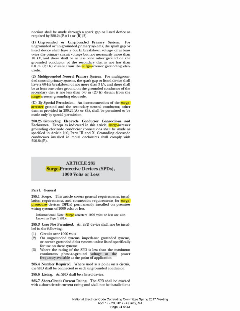
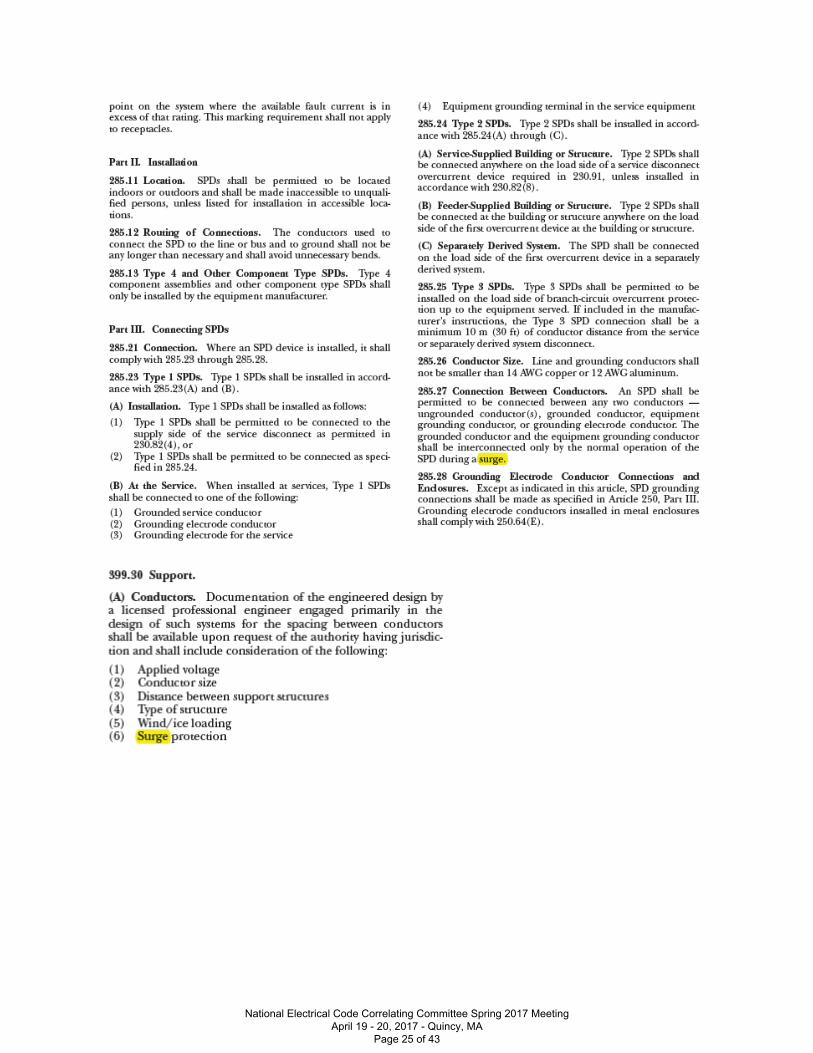
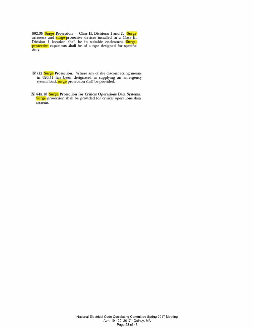
Surge Protection in the NEC
For the convenience of the Correlating Committee, the following requirements, with highlighted surge protection requirements, have been copied and pasted from the 2017 NEC. An additional file is provided to show what a consolidated surge protection Article might look like (Article 242). It is color coded to show directly extracted text, minimally modified text, and new text.
National Electrical Code Correlating Committee Spring 2017 Meeting April 19 - 20, 2017 - Quincy, MA
Page 16 of 43

National Electrical Code Correlating Committee Spring 2017 Meeting April 19 - 20, 2017 - Quincy, MA
Page 17 of 43

National Electrical Code Correlating Committee Spring 2017 Meeting April 19 - 20, 2017 - Quincy, MA
Page 18 of 43

National Electrical Code Correlating Committee Spring 2017 Meeting April 19 - 20, 2017 - Quincy, MA
Page 19 of 43

National Electrical Code Correlating Committee Spring 2017 Meeting April 19 - 20, 2017 - Quincy, MA
Page 20 of 43

National Electrical Code Correlating Committee Spring 2017 Meeting April 19 - 20, 2017 - Quincy, MA
Page 21 of 43

National Electrical Code Correlating Committee Spring 2017 Meeting April 19 - 20, 2017 - Quincy, MA
Page 22 of 43

National Electrical Code Correlating Committee Spring 2017 Meeting April 19 - 20, 2017 - Quincy, MA
Page 23 of 43
National Electrical Code Correlating Committee Spring 2017 Meeting April 19 - 20, 2017 - Quincy, MA
Page 24 of 43
National Electrical Code Correlating Committee Spring 2017 Meeting April 19 - 20, 2017 - Quincy, MA
Page 25 of 43

National Electrical Code Correlating Committee Spring 2017 Meeting April 19 - 20, 2017 - Quincy, MA
Page 26 of 43
National Electrical Code Correlating Committee Spring 2017 Meeting April 19 - 20, 2017 - Quincy, MA
Page 27 of 43
National Electrical Code Correlating Committee Spring 2017 Meeting April 19 - 20, 2017 - Quincy, MA
Page 28 of 43

National Electrical Code Correlating Committee Spring 2017 Meeting April 19 - 20, 2017 - Quincy, MA
Page 29 of 43

National Electrical Code Correlating Committee Spring 2017 Meeting April 19 - 20, 2017 - Quincy, MA
Page 30 of 43

National Electrical Code Correlating Committee Spring 2017 Meeting April 19 - 20, 2017 - Quincy, MA
Page 31 of 43

Proposed New Article 242 – Overvoltage Protection
Key for color scheme
Exact text taken from Articles 280 and 285
Minor changes from Articles 280 and 285 necessary to integrate into one Article
New material
Article 242
Overvoltage Protection
Part I. General
242.1 Scope. This article provides the general requirements, installation requirements, and connection
requirements for overvoltage protection and overvoltage protective devices. Part II covers Surge
Protective Devices (SPDs) permanently installed on premises wiring systems of not more than 1000
volts, nominal, while Part III covers surge arresters permanently installed on premises wiring systems
over 1000 volts, nominal.
242.3 Other Articles. Equipment shall be protected against overvoltage in accordance with the article
in this Code that covers the type of equipment or location specified in Table 242.3
Table 242.3 Other Articles
Equipment Article
Class I locations 501
Class II locations 502
Community antenna television and radio distribution systems
820
Critical operations power systems 708
Elevators, dumbwaiters, escalators, moving walks, platform lifts, and stairway chairlifts
620
Emergency systems 700
Equipment over 1000 volts nominal 490
Fire pumps 695
Industrial Machinery 670
Information Technology Equipment 645
Modular data centers 646
Outdoor overhead conductors over 1000 volts
399
Radio and television equipment 810
Receptacles, Cord Connectors, and Attachment Plugs (Caps)
406
National Electrical Code Correlating Committee Spring 2017 Meeting April 19 - 20, 2017 - Quincy, MA
Page 32 of 43

Wind electric systems 694
Part II Surge-Protective Devices (SPDs), 1000 Volts or Less
Informational Note: Surge arresters 1000 volts or less are also known as Type 1 SPDs.
242.4 Service Requirements. All services shall be provided with a surge protective device (SPD).
(A) Location. The surge protective device shall be an integral part of the service disconnecting means or shall be located immediately adjacent thereto.
(B) Type. The surge protective device shall be a Type 1 or Type 2 SPD.
(C) Replacement. Where service equipment is upgraded, all of the requirements of this section shall apply.
242.5 Outside Feeder Requirements. All outside feeders supplying buildings or other structures shall include a listed Type 1 or Type 2 surge protective device (SPD). The SPD shall be located in the disconnecting means, or immediately adjacent to the disconnecting means that is required by 225.31.
Exception: Surge protection is not required for non-habitable buildings or other structures supplied from outside feeders that originate in one- and two-family dwellings.
242.6 Uses Not Permitted. An SPD device shall not be installed in the following:
(1) Circuits over 1000 volts
(2) On ungrounded systems, impedance grounded systems, or corner grounded delta systems unless
listed specifically for use on these systems
(3) Where the rating of the SPD is less than the maximum continuous phase-to-ground voltage at the
power frequency available at the point of application
242.7 Number Required. Where used at a point on a circuit, the SPD shall be connected to each
ungrounded conductor.
242.9 Listing. An SPD shall be a listed device.
242.11 Short-Circuit Current Rating. The SPD shall be marked with a short-circuit current rating and
shall not be installed at a point on the system where the available fault current is in excess of that rating.
This marking requirement shall not apply to receptacles.
242.13 Location. SPDs shall be permitted to be located indoors or outdoors and shall be made
inaccessible to unqualified persons, unless listed for installation in accessible locations.
242.15 Routing of Connections. The conductors used to connect the SPD to the line or bus and to
ground shall not be any longer than necessary and shall avoid unnecessary bends.
National Electrical Code Correlating Committee Spring 2017 Meeting April 19 - 20, 2017 - Quincy, MA
Page 33 of 43
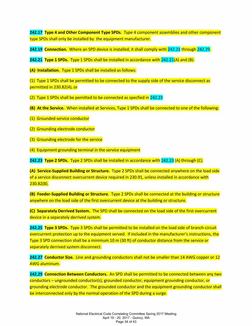
242.17 Type 4 and Other Component Type SPDs. Type 4 component assemblies and other component
type SPDs shall only be installed by the equipment manufacturer.
242.19 Connection. Where an SPD device is installed, it shall comply with 242.21 through 242.29.
242.21 Type 1 SPDs. Type 1 SPDs shall be installed in accordance with 242.21(A) and (B).
(A) Installation. Type 1 SPDs shall be installed as follows:
(1) Type 1 SPDs shall be permitted to be connected to the supply side of the service disconnect as
permitted in 230.82(4), or
(2) Type 1 SPDs shall be pemitted to be connected as specfied in 242.23
(B) At the Service. When installed at Services, Type 1 SPDs shall be connected to one of the following:
(1) Grounded service conductor
(2) Grounding electrode conductor
(3) Grounding electrode for the service
(4) Equipment grounding terminal in the service equipment
242.23 Type 2 SPDs. Type 2 SPDs shall be installed in accordance with 242.23 (A) through (C).
(A) Service-Supplied Building or Structure. Type 2 SPDs shall be connected anywhere on the load side
of a service disconnect overcurrent device required in 230.91, unless installed in accordance with
230.82(8).
(B) Feeder-Supplied Building or Structure. Type 2 SPDs shall be connected at the building or structure
anywhere on the load side of the first overcurrent device at the building or structure.
(C) Separately Derrived System. The SPD shall be connected on the load side of the first overcurrent
device in a separately derrived system.
242.25 Type 3 SPDs. Type 3 SPDs shall be permitted to be installed on the load side of branch-circuit
overcurrent protection up to the equipment served. If included in the manufacturer’s instructions, the
Type 3 SPD connection shall be a minimum 10 m (30 ft) of conductor distance from the service or
separately derrived system disconnect.
242.27 Conductor Size. Line and grounding conductors shall not be smaller than 14 AWG copper or 12
AWG aluminum.
242.29 Connection Between Conductors. An SPD shall be permitted to be connected between any two
conductors – ungrounded conductor(s), grounded conductor, equipment grounding conductor, or
grounding electrode conductor. The grounded conductor and the equipment grounding conductor shall
be interconnected only by the normal operation of the SPD during a surge.
National Electrical Code Correlating Committee Spring 2017 Meeting April 19 - 20, 2017 - Quincy, MA
Page 34 of 43

242.31 Grounding Electrode Conductor Connections and Enclosures. Except as indicated in this article,
SPD grounding connections shall be made as specified in Article 250, Part III. Grounding electrode
conductors installed in metal enclosures shall comply with 250.64(E).
Part III Surge Arresters, Over 1000 Volts
242.41 Number Required. Where used at a point on a circuit, a surge arrester shall be connected to
each ungrounded conductor. A single installation of such surge arresters shall be permitted to protect a
number of interconnected circuits, if no circuit is exposed to surges while disconnected from the surge
arresters.
242.43 Surge Arrester Selection. The surge arresters shall comply with 242.43(A) and (B).
(A) Rating. The rating of a surge arrester shall be equal to or greater than the maximum continuous
operating voltage available at the point of application.
(1) Solidly Grounded Systems. The maximum continuous operating voltage shall be the phase-to-
ground voltage of the system.
(2) Impedance or Ungrounded System. The maximum continuous operating voltage shall be the phase-
to-phase voltage of the system.
(B) Silicon Carbide Types. The rating of a silicon carbide-type surge arrester shall be not less than 125
percent of the rating specified in 242.43(A).
Informational Noet No. 1: For further information on surge arresters, see IEEE C62.11-2012, Standard
for Metal-Oxide Surge Arresters for Alternating-Current Power Circuits (>1 kV), and IEEE C62.22-2009,
Guide for the Application of Metal-Oxide Surge Arresters for Alternating-Current Systems.
Informational Note No. 2: The selection of a properly rated metal oxide arrester is based on
considerations of maximum continuous operating voltage and the magnitude amd duration of
overvoltages at the arrester location as affected by phase-to-ground faults, system grounding
techniques, switching surges, and other causes. See the manufacturer’s application rules for selection of
the specific arrester to be used at a particular location.
242.45 Location. Surge arresters shall be permitted to be located indoors or outdoors. Surge arresters
shall be made inaccessible to unqualified persons, unless listed for installation in accessible locations.
242.47 Uses Not Permitted. A surge arrester shall not be installed where the rating of the surge
arrester is less than the maximum continuous phase-to-ground voltage at the power frequency available
at the point of application.
242.49 Routing of Surge Arrester Grounding Conductors. The conductor used to connect the surge
arrester to line, bus, or equipment and to a grounding conductor connection point as provided in 242.51
shall not be any longer than necessary and shall avoid unnecessary bends.
National Electrical Code Correlating Committee Spring 2017 Meeting April 19 - 20, 2017 - Quincy, MA
Page 35 of 43

242.51 Connection. The arrester shall be connected to one of the following:
(1) Grounded service conductor
(2) Grounding electrode conductor
(3) Grounding electrode for the service
(4) Equipment grounding terminal in the service equipment
242.53 Surge-Arrester Conductors. The conductor between the surge arrester and the lilne and the
surge arrester and the grounding connection shall not be smaller than 6 AWG copper or aluminum.
242.55 Interconnections. The surge arrester protecting a transformer that supplies a secondary
distribution system shall be interconnected as specified in 242.55(A), (B), or (C).
(A) Metal Interconnections. A metal interconnection shall be made to the secondary grounded circuit
conductor or the secondary circuit grounding electrode conductor, if, in addition to the direct grounding
connection at the surge arrester, the following occurs:
(1) Additional Grounding Connection. The grounded conductor of the secondary has elsewhere a
grounding connection to a continuous metal underground water piping system. In urban water-pipe
areas where there are at least four water-pipe connections on the neutral conductor and not fewer than
four such connections in each mile of neutral conductor, the metal interconnection shall be permitted to
be made to the secondary neutral conductor with omission of the direct grounding connection at the
surge arrester.
(2) Multigrounded Neutral System Connection. The grounded conductor of the secondary system is
part of a multigrounded neutral system or static wire of which the primary neutral conductor or static
wire has at least four grounding connections in each 1.6 km (1 mile) of line in addition to a grounding
connection at each service.
(B) Through Spark Gap or Device. Where the surge arrester grounding electrode conductor is not
connected as in 242.55(A), or where the secondary is not grounded as in 242.55(A) but is otherwise
grounded as in 250.52, an interconnection shall be made through a spark gap or listed device as
required by 242.55(B)(1) or (B)(2).
(1) Ungrounded or Unigrounded Primary System. For ungrounded or unigrounded primary systems,
the spark gap for listed device shall have a 60-Hz breakdown voltage of at least twice the primary circuit
voltage but not necessarily more than 10 kV, and there shall be at least one other ground on the
grounded conductor of the secondary that is not less than 6.0 m (20 ft) distant from the surge-arrester
grounding electrode.
(2) Multigrounded Neutral Primary System. For multigrounded neutral primary systems, the spark gap
or listed device shall have a 60-Hz breakdown of not more than 3kV, and there shall be at least one
National Electrical Code Correlating Committee Spring 2017 Meeting April 19 - 20, 2017 - Quincy, MA
Page 36 of 43

other ground on the grounded conductor of the secondary that is not less than 6.0 m (20 ft) distant from
the surge-arrester grounding electrode.
(C) By Special Permission. An interconnection of the surge-arrester ground and the secondary neutral
conductor, other than as provided in 242.55(A) or (B), shall be permitted to be made only by special
permission.
242.57 Grounding Electrode Conductor Connections and Enclosures. Except as indicated in this article,
surge-arrester grounding electrode conductor connections shall be made as specified in Article 250,
Parts III and X. Grounding electrode conductors installed in metal enclosures shall comply with
250.64(E).
National Electrical Code Correlating Committee Spring 2017 Meeting April 19 - 20, 2017 - Quincy, MA
Page 37 of 43

Simplification of Articles 725, 760, 770, 800, 810, 820, 830, 840
Examples
Concentrating on Article 760, the listing and application requirements for both non-power limited and
power limited fire alarm cables are restated in most cases three times.
Listing Requirements 760.133 requires all PLFA cables to be listed.
(A) Listing. PLFA cables installed in buildings shall be listed. Application Requirements 760.135(C)
(C) Other Spaces Used For Environmental Air (Plenums). The following cables shall be permitted
in other spaces used for environmental air as described in 300.22(C):
(1) Type FPLP cables
(2) Type FPLP cables installed in plenum communications raceways
(3) Type FPLP cables installed in plenum routing assemblies
(4) Types FPLP and FPLP-CI cables supported by open metallic cable trays or cable tray
systems
(5) Types FPLP, FPLR, and FPL cables installed in raceways that are installed in
compliance with 300.22(C)
(6) Types FPLP, FPLR, and FPL cables supported by solid bottom metal cable trays with solid
metal covers in other spaces used for environmental air (plenums) as described in 300.22(C)
(7) Types FPLP, FPLR, and FPL cables installed in plenum communications raceways, riser
communications raceways, or general-purpose communications raceways supported by solid
bottom metal cable trays with solid metal covers in other spaces used for environmental air
(plenums) as described in 300.22(C)In section 760.179 the same idea is restated differently.
Repeating of Listing and Application requirements
Section 760.179 repeats the listing requirements in 760.133
(D) Type FPLP. Type FPLP power-limited fire alarm plenum cable shall be listed as being suitable for use in ducts, plenums, and other space used for environmental air and shall also be listed as having adequate fire-resistant and low smoke-producing characteristics.
Repeating of listing and application requirements in Table format - 760.154
National Electrical Code Correlating Committee Spring 2017 Meeting April 19 - 20, 2017 - Quincy, MA
Page 38 of 43

National Electrical Code Correlating Committee Spring 2017 Meeting April 19 - 20, 2017 - Quincy, MA
Page 39 of 43

Fire Alarm Riser Cable - Example
(D) Risers — Cables in Vertical Runs. The following cables shall be permitted in vertical runs penetrating one or more floors and in vertical runs in a shaft:
(1) Types FPLP and FPLR cables (2) Types FPLP and FPLR cables installed in the following:
a. Plenum communications raceways b. Plenum cable routing assemblies c. Riser communications raceways d. Riser cable routing assemblies Informational Note: See 3
(E) Type FPLR. Type FPLR power-limited fire alarm riser cable shall be listed as being suitable for use in a vertical run in a shaft or from floor to floor and shall also be listed as having fire-resistant characteristics capable of preventing the carrying of fire from floor to floor. Informational Note: One method of defining fire-resistant characteristics capable of preventing the carrying of fire from floor to floor is that the cables pass the requirements of ANSI/UL 1666-2012, Standard Test for Flame Propagation Height of Electrical and Optical-Fiber Cable Installed Vertically in Shafts.
National Electrical Code Correlating Committee Spring 2017 Meeting April 19 - 20, 2017 - Quincy, MA
Page 40 of 43

Examples of common themed requirements used throughout articles under purview of CMP 3 and
CMP 16
760.3 (J) Number and Size of Cables and Conductors in Raceway. Installations shall comply with 300.17. 760.3 (L) Cable Routing Assemblies. Power-limited fire alarm cables shall be permitted to be installed in plenum cable routing assemblies, riser cable routing assemblies, and general-purpose cable routing assemblies selected in accordance with Table 800.154(c), listed in accordance with the provisions of 800.182, and installed in accordance with 800.110(C) and 800.113. 760.3 (M) Communications Raceways. Power-limited fire alarm cables shall be permitted to be installed in plenum communications raceways, riser communications raceways, and general purpose communications raceways selected in accordance with Table 800.154(b), listed in accordance with the provisions of 800.182, and installed in accordance with 800.113 and 362.24 through 362.56, where the requirements applicable to electrical nonmetallic tubing apply. 760.21 Access to Electrical Equipment Behind Panels Designed to Allow Access. Access to electrical equipment shall not be denied by an accumulation of conductors and cables that prevents removal of panels, including suspended ceiling panels. 760.24 Mechanical Execution of Work. (A) General. Fire alarm circuits shall be installed in a neat workmanlike manner. Cables and conductors installed exposed on the surface of ceilings and sidewalls shall be supported by the building structure in such a manner that the cable will not be damaged by normal building use. Such cables shall be supported by straps, staples, cable ties, hangers, or similar fittings designed and installed so as not to damage the cable. The installation shall also comply with 300.4(D). 760.25 Abandoned Cables. The accessible portion of abandoned fre alarm cables shall be removed. Where cables are identified for future use with a tag, the tag shall be of sufficient durability to withstand the environment involved.
770.24 Mechanical Execution of Work. Optical fiber cables shall be installed in a neat and workmanlike manner. Cables installed exposed on the surface of ceilings and sidewalls shall be supported by the building structure in such a manner that the cable will not be damaged by normal building use. Such cables shall be secured by hardware including straps, staples, cable ties, hangers, or similar fittings designed and installed so as not to damage the cable. The installation shall also conform with 300.4(D) through (G) and 300.11. Nonmetallic cable ties and other nonmetallic cable accessories used to secure and support cables in other spaces used for environmental air (plenums) shall be listed as having low smoke and heat release properties.
National Electrical Code Correlating Committee Spring 2017 Meeting April 19 - 20, 2017 - Quincy, MA
Page 41 of 43

770.25 Abandoned Cables. The accessible portion of abandoned optical fber cables shall be removed. Where cables are identifed for future use with a tag, the tag shall be of sufficient durability to withstand the environment involved. 800.21 Access to Electrical Equipment Behind Panels Designed to Allow Access. Access to electrical equipment shall not be denied by an accumulation of communications wires and cables that prevents removal of panels, including suspended ceiling panels. 800.24 Mechanical Execution of Work. Communications circuits and equipment shall be installed in a neat and workmanlike manner. Cables installed exposed on the surface of ceilings and sidewalls shall be supported by the building structure in such a manner that the cable will not be damaged by normal building use. Such cables shall be secured by hardware, including straps, staples, cable ties, hangers, or similar fittings, designed and installed so as not to damage the cable. The installation shall also conform to 300.4(D) and 300.11. Non-metallic cable ties and other nonmetallic cable accessories used to secure and support cables in other spaces used for environmental air (plenums) shall be listed as having low smoke and heat release properties in accordance with 800.170(C). 800.25 Abandoned Cables. The accessible portion of abandoned communications cables shall be removed. Where cables are identified for future use with a tag, the tag shall be of sufficient durability to withstand the environment involved. 800.26 Spread of Fire or Products of Combustion. Installations of communications cables, communications raceways, cable routing assemblies in hollow spaces, vertical shafts, and ventilation or air-handling ducts shall be made so that the possible spread of fre or products of combustion will not be substantially increased. Openings around penetrations of communications cables, communications raceways, and cable routing assemblies through fre-resistant-rated walls, partitions, floors, or ceilings shall be fire stopped using approved methods to maintain the fire resistance rating.
National Electrical Code Correlating Committee Spring 2017 Meeting April 19 - 20, 2017 - Quincy, MA
Page 42 of 43

Examples of Standards Addressing EMC
1. ETSI EN 300 386, Electromagnetic Compatibility and Radio Spectrum Matters (ERM); Telecommunication Network Equipment; ElectroMagnetic Compatibility (EMC) Requirements.
2. IEEE C63.4-2009 or ANSI C63.4-2003, American National
Standard for Methods of Measurement of Radio-Noise Emissions from Low-Voltage Electrical and Electronic Equipment in the Range of 9 kHz to 40 GHz.
3. IEEE C63.2-2009, American National Standard for Electromagnetic
Noise and Field Strength Instrumentation, 10 Hz to 40 GHz Specifications.
4. CISPR 16-1-1 (2010-2011), Edition 3.1, Specification for radio
disturbance and immunity measuring apparatus and methods - Part 1-1: Radio disturbance and immunity measuring apparatus - Measuring apparatus.
5. MIL-STD-461E, 20 August 1999, Requirements for the control of
electromagnetic interference characteristics of subsystems and equipment.
6. CISPR 16-1-2 (2006), Specification for radio disturbance and
immunity measuring apparatus and methods - Part 1-2: Radio disturbance and immunity measuring apparatus - Ancillary equipment – Conducted disturbances.
7. IEEE C63.5-2006, American National Standard for Electromagnetic
Compatibility - Radiated Emission Measurements in Electromagnetic Interference (EMI) Control - Calibration of Antennas (9 kHz to 40 GHz).
8. IEEE C63.7-2005, American National Standard Guide for
Construction of Open-Area Test Sites for Performing Radiated Emission Measurements.
9. IEEE C63.6-1996, American National Standard Guide for the
Computation of Errors in Open-Area Test Site Measurements.
10. IEEE C63.12-1999, American National Standard Recommended Practice for Electromagnetic Compatibility Limits.
11. CISPR 22 (2005), Fifth Edition, Information Technology Equipment
– Radio Disturbance Characteristics - Limits and Methods of Measurement.
National Electrical Code Correlating Committee Spring 2017 Meeting April 19 - 20, 2017 - Quincy, MA
Page 43 of 43


![Page 1 of 51 - nfpa.org · PDF fileSecond Correlating Revision No. 15-NFPA 61-2015 [ Global Input ] See attached file for updates to Chapter 8 numbering. Supplemental Information](https://static.fdocuments.us/doc/165x107/5a7a34117f8b9a6c3c8cb9e9/page-1-of-51-nfpaorg-correlating-revision-no-15-nfpa-61-2015-global-input.jpg)