
NATIONAL EARLY WARNING AND FOOD INFORMATION SYSTEM
24
Palmer 2004 pCO2 System Users Manual Under way pCO 2 System Users Manual Timothy Newberger Lamont-Doherty Earth Observatory of Columbia University P.O Box 1000 Rt. 9W Palisades, NY 10964 NBPpCO2man.doc 15-Nov-04
Transcript of NATIONAL EARLY WARNING AND FOOD INFORMATION SYSTEM

Palmer 2004 pCO2 System Users Manual
Under way pCO2 System Users Manual
Timothy Newberger Lamont-Doherty Earth Observatory of Columbia University
P.O Box 1000 Rt. 9W Palisades, NY 10964
NBPpCO2man.doc 15-Nov-04

Palmer 2004 pCO2 System Users Manual
Table of Contents
STARTUP………………………………………………………………………………………………………………….3 SHUTTING DOWN…………………………………………………………………………………………………………4 ADDITIONAL NOTES AND TASKS…………………………………………………………………………………………4 DAILY CHECKS………………………………………………………………………………………………………...…4 RECENT CHANGES…………………………………………………………………………………………………….….5 SYSTEM DESCRIPTION…………………………………………………………………………………………………....5 EQUILIBRATOR………………………………………………………………………………………….…...….6 WATER MANOMETER……………………………………………………………………………………...……7 THE ANALYZER………………………………………………………………………………………………....8 INFRA-RED CO2 ANALYZER………………………………………………………………………….……..….8 PERMEATION GAS DRYER……………………………………………………………………………………....8 MULTI-POSITION SELECTOR VALVE…………………………………………………………………….…...….9 FLOW METER……………………………………………………………………………………………………9 RTD TEMPERATURE PROBE…………………………………………………………………………………….9 A/D MODULES…………………………………………………………………………………………..…….10 PUMPS…………………………………………………………………………………………………...…….10 SYSTEM OPERATION, DETAILS………………………………………………………………………………….………11 CO2 STANDARDS AND N2 GAS………………………………………………………………………..…...….11 EQUILIBRATOR AND ATMOSPHERIC SAMPLES………………………………………………………..……….12 EQUILIBRATOR SAMPLES…………………………………………………………………………….….…….12 ATMOSPHERIC SAMPLES………………………………………………………………………………………13 SOFTWARE START UP………………………………………………………………………………………….13 UNDERWAY OPERATION………..……………………………………………………………………………….…..….14 GAS FLOW RATES…………………………………………………………………………………….……….14 SHUT DOWN PROCEDURE……………………………………………………………………………………..15 TROUBLE SHOOTING…………………………………………………………………………………………………….15 LITTLE OR NO EQUILIBRATOR SAMPLE FLOW………………………………………………………………….15 EXCESSIVE EQUILIBRATOR FLOW……………………………………………………………………………...15 LITTLE OR NO ATMOSPHERIC SAMPLE FLOW………………………………………………………...………...16 FLOW DISRUPTION FROM VALVE MISALIGNMENT……………………………………………………………...16 VALVE STEPPING IN WRONG DIRECTION.………………………………………………………………………16 ICE IN EQUILIBRATOR………………………………………………………………………………………….16 NO COMMUNICATION BETWEEN COMPUTER AND CO2 ANALYZER BOX.………………………………...…….16 APPENDIX 1 SYSTEM INSTALLATION……………………………………………………………………………………17 MOUNTING THE EQUILIBRATOR……………………………………………………………………………….17 PLUMBING THE SEAWATER INLET……………………………………………………………………………..17 OTHER EQUILIBRATOR ATTACHMENTS……………………………………………………………….……….17 MOUNTING THE ANALYZER Box……………………………………………………………………….………………17 PUMP CONNECTIONS……………………………………………………………………...…………………...18 CONNECTING THE STANDARDS AND NITROGEN……………………………………………………………….18 ELECTRICAL CONNECTIONS……………………………………………...……………………………………19 SAFETY PRECAUTIONS…………………………………………………………………………………………………..19 APPENDIX 2 A DIAGNOSTIC PROGRAM…………………………………………………………...……………….…….20 APPENDIX 3 TOTAL CARBON (TCO2) SAMPLES…………………………………………………………………………20 SAMPLE SHIPPING INSTRUCTIONS:…………………………………………………………………….……….21 APPENDIX 4: SYSTEM WIRING……………………………………………………………..………………….………..22 APPENDIX 5: A/D MODULE CONFIGURATION……………………………………………………………..…….………23
NBPpCO2man.doc 15-Nov-04 2

Palmer 2004 pCO2 System Users Manual
Lamont-Doherty Earth Observatory Underway pCO2 System Startup
Adjust the seawater flow to the equilibrator to about 10 liters per minute.
1. Turn the instrument power strip switch on. 2. Turn the Li-Cor CO2 analyzer on, (Toggle the
small switch to Down then back Up.) Note: The small green light on the IR box will come on in a few minutes.
3. Open the valves on the nitrogen and standard gas cylinders. Set the output pressures to about 3-5 psi on all cylinders. 4. Set the flows of the standard gases.
a) Step the multi-position valve to Position 1, Adjust the flow to about 60 ml/min using the N2 needle valve.
b) Step the multi-position valve to each next odd position, and adjust the flows to 60 ml/min for each corresponding standard using the needle valve for each standard.
5. Step to an even position. Turn the Gas Flow Meter (GFM) selection valve to the “Ref/Dry” position.
a) The flow should be between 120-150
ml/min. b) Return the GFM selection valve to the
“Samples/Standards” position.
6. Turn on the atmosphere and equilibrator pumps.
a) Set the flow rate for the equilibrator pump. Step the multi-position valve to position 13. Set the flow to about 50 using the needle valve labeled “Equil.”. If necessary the pump speed can be adjusted with the knob potentiometer on the pump box and the backpressure valve controlling the return flow to the equilibrator can be adjusted as well. The goal is to set the pump speed near its minimal operating rate, have about 4 bubbles per second at the equilibrator return line and get the proper flow through the analyzer.
b) Set the flow of the atmosphere pump. Step the multi-position valve to position 15. Adjust the flow to about 60 ml/min using the needle valve labeled “Atmos.”. The backpressure valve should be as open as possible thus venting most of the flow from this pump to the room and ensuring adequate flushing of the long tube that leads to the bow of the ship.
c) Step the multi-position valve to Home.
7. Start the computer. 8. Adjust the computer time to GMT (right click
the clock on the lower right of the computer screen).
9. Click on the Shortcut Icon to open the Labview
NBPuwpCO2.vi program. a) In the Setup window, check to see that
the standards serial #’s and CO2 concentrations match those on the cylinders.
b) Switch the program from Edit to Run mode by Choosing Operations>>Change to Run Mode. (This is to prevent accidental “program editing”).
NBPpCO2man.doc 15-Nov-04 3
Palmer 2004 pCO2 System Users Manual
10. Start the program by clicking on the little white arrow in the upper left corner. Notice it will change to a black arrow of a different shape.
11. Click on “Run Time Display” to bring up the
graphic data display window. This is a good time to check the flow rates and make additional adjustments if necessary as the program steps through each standard.
12. Log any info such as startup time, shut down
time, cylinder pressures and any other activities) in the logbook with the GMT date and time.
Shutting Down 1) Click on the dark green “Stop Sampling, Run
Standards” button in the upper right side of the run time display window. This will initiate a final run of standards. Wait for the program to complete this final run of standards before proceeding.
a) Exit the program. b) Shut down the computer.
2) Turn off the power to the instrument. 3) Turn off the atmosphere and equilibrator pumps. 4) FIRMLY CLOSE THE VALVES ON THE
NITROGEN AND STANDARD GAS CYLINDERS.
5) Turn off the seawater flow to the equilibrator. 6) Drain the equilibrator by opening the drain valve
underneath. 7) Rinse the equilibrator with fresh water and let
drain. Connect the larger diameter end of the siphon breaker purge hose (a Tygon tubing assembly) to the fresh water at the sink. Thread the small diameter end up through the siphon breaker tube on the equilibrator and slowly turn
on the fresh water to wash salts from the siphon breaker.
. Additional Notes and Tasks 1) Record cylinder pressures each week in the
notebook. The standard gases (excluding nitrogen) should last years so a large pressure drop in a short time indicates a leak!
2) Check the date on the hydrophobic membrane filters; change if filters have been installed for 2 months or longer.
3) Record any pertinent events, changes, adjustments and comments etc… concerning the pCO2 system, include date and GMT time with your notes.
4) Maintain the water level in the manometer to the black line using distilled water only. The amount of water in the manometer affects the water level (and therefore the pressure) in the equilibrator so it is best to not overfill it.
5) Wash salts from the siphon breaker as needed, a once per cruise should suffice.
6) Check the manometer tube for salt buildup occasionally and wash if necessary.
Daily Checks 1. Acceptable flow ranges.
- nitrogen standard 50-65 ml/min - standards 50-65 ml/min - equil. 40-55 ml/min - atmosphere 50-65 ml/min
2. Maintain the water level in the manometer. 3. Check the water flow to the equilibrator. 4. Log any changes to the system in GMT. 5. Change N2 cylinder when low but before it is
empty. Contacts: Tim Newberger [email protected]
NBPpCO2man.doc 15-Nov-04 4

Palmer 2004 pCO2 System Users Manual
Recent Changes The new underway pCO2 system installed in December 2003 on the R.V. Nathaniel B. Palmer incorporates design changes that should provide more accurate pCO2 measurements and simplify system operation. The primary change in the system was the elimination of two solenoid valves that coupled with a Valco multi-position selector valve, were used to select the various gases being delivered to the CO2 analyzer. The functions of the solenoid valves and the old multi-position valve were replaced with an 8-port, 16 position Valco valve driven by a micro-actuator. This valve now handles the flows of the both the standards and the sample gases. This replacement was possible because the rotation direction of the micro-actuator is programmable thus allowing the valve to be used in a manner much like the solenoid valves to stop and start the flow of the sample gas streams without having to cycle the valve through a full rotation, which would introduce small amounts of gas from each port it rotates past. This arrangement allowed a much simpler flow path for the gas streams and eliminated the dead volume and heating cycle problems of the solenoid valves. With this arrangement it is no longer necessary to manually activate solenoids to open the flow path when adjusting the flows for the standards and samples. It is only necessary to step the valve to the appropriate position for each standard and sample gas stream. A new Oxygen sensor has been added to the underway seawater measurements (presently on Lawrence M. Gould system only). A Labview script embedded in the LMGuwpCO2 program drives the sensor. The oxygen data is written every 60 seconds to a separate file on the pCO2 computer in the C:\Gould2004\data2 directory and is logged on the RVDAS system as well. The sensor is mounted in a flow through housing constructed of PVC fittings and is located next to the pCO2 equilibrator. A gentle seawater flow should be
maintained through the housing. A vigorous flow will decrease the life of the sensor’s foil membrane. A new modular pump setup for delivering the equilibrator and atmospheric samples to the analyzer also has been incorporated in this system. The atmospheric pump head has been machined and fitted with O-rings to make it less prone to leaks. New plastic compression fittings with O-ring seals have replaced the Swagelok fittings for connections to the Synflex Dekoron tubing. The manometer for the equilibrator has been redesigned to minimize the head and the change in head as the air passes through it, thus minimizing pressure changes in the equilibrator and the overall pressure differential between the head space in the equilibrator and the ambient laboratory air. It also incorporates a larger diameter tube that connects it to the equilibrator to decrease the likelihood of a salt blockage. With the new O-ring sealed nylon compression fittings this tube is easily removed for cleaning and inspection. Vacushield hydrophobic membrane filters are now installed on the air outlet of the equilibrator and on the atmospheric intake at the pump box. These filters prevent the passage of liquid water as well as remove aerosols from the sample gas streams. A 4-inch muffin fan has been added to the pCO2 cabinet to reduce the difference in temperature between the lab and the pCO2 cabinet. System Description The prototype of this system was operated on the WOCE S4P leg in the Pacific sector of the Southern Ocean (R/V Akademik Ioffe, Feb.-Apr. 1992) and on the R/V Ewing. It is currently in continuous operation on the United States Antarctic Program research vessels, the Nathaniel B. Palmer and the Lawrence M. Gould. The pCO2 analysis system has several major components; a seawater/air equilibrator, a computer
NBPpCO2man.doc 15-Nov-04 5

Palmer 2004 pCO2 System Users Manual
controlled analysis system, a pair of air pumps for delivering the sample gas streams, 4 or 5 cylinders of CO2 in air calibration standards, 1 cylinder of N2 and a Nafion sample drying column. The analysis system is driven by a laptop computer using Labview programs to control, via separate A/D modules, switching of a multi-position selector valve, reading of various sensors (IR millivolts, IR cell temperature, equilibrator water temperature, flow rate and barometric pressure) and writing of data to files. A LI-COR 6251 infrared analyzer is used to measure the concentration of CO2 in the gas stream. The partial pressure of CO2 is calculated using ambient atmospheric pressure and temperature at the time of measurement. The pCO2 system data file is ultimately merged with the vessel underway data that includes navigation, meteorological and surface seawater sensor data. Equilibrator The seawater equilibrator, shown diagrammatically in Figure 1, is based on a design used by Takahashi during the GEOSECS expedition (Takahashi, 1966). A continuous flow of seawater enters a closed equilibration chamber through a spiral cone spray nozzle, producing a fine-fanned spray, which enhances the rate of gas exchange between water and the overlying air. A small pump continuously re-circulates the headspace air at 100-150 ml min-1. A small amount of the re-circulated air (nominally 50 ml min-1) is diverted to the analyzer. The air removed for analysis is replaced by means of a "controlled leak" into the equilibrator through a water-manometer, which allows the rate of replacement to be monitored and which further assures that the pressure within the equilibrator headspace is not significantly different from the ambient pressure in the laboratory. The temperature of the water in the equilibrator is measured with a platinum resistance thermometer (RTD), which is calibrated against high-precision mercury thermometers traceable to N.I.S.T. The flow of water into the equilibrator is kept great enough that the residence time for water is approximately 2 minutes (at a flow of ~ 10 L/min), while the
residence time for air is approximately 6 hours (at a flow of 50 ml/min).
The equilibrator does not require much adjustment once the seawater flow has been set. A ball valve in the inlet line can be closed or opened to reduce or increase the seawater flow, or closed completely in the event of leaking, flooding or for end of cruise shut down. The spray nozzle is attached to the end of a PVC pipe that is attached to the equilibrator top plate by means of an airtight nylon cord grip fitting and a PVC flange. To remove the water-inlet assembly, simply loosen the nut on the nylon cord-grip fitting. The spray nozzle assembly can then be lifted out of the equilibrator. The nylon spiral cone spray nozzle can be unscrewed from the pipe for cleaning if necessary but clogging is rarely a problem.
Figure 1. pCO2 equilibrator
NBPpCO2man.doc 15-Nov-04
6

Palmer 2004 pCO2 System Users Manual
The water drains from the equilibrator by gravity, spilling over the top of a 1 1/4 inch standpipe that is inside the white 4 inch PVC tower. The PVC tower and the siphon breaker tube are necessary to isolate the air space in the equilibrator from the laboratory air and still allow water to freely pass through. It is essential that both the seawater drain and the siphon breaker tube remain unimpeded. The optimal configuration for the drain is to allow it to drop directly into an open sink with no additional plumbing attached. If additional plumbing is added especially a line with turns or elbows there is potential for a back up to occur that will result in overfilling the equilibrator and possibly flooding the analyzer as well. In the event that the siphon breaker tube becomes restricted or blocked, it is likely that water will periodically siphon from the equilibrator causing the pressure of air in the equilibrator to fluctuate greatly. The result is an excessive exchange ("breathing") between the equilibrator headspace and the laboratory atmosphere indicated by radical water level changes in the equilibrator and by a 2-way air exchange through the water manometer. No meaningful measurements can be obtained under these circumstances. A second drain port on the underside of the equilibrator is fitted with a ball valve that allows the equilibrator to be emptied completely for servicing and cleaning or draining accumulated ice particles.
The equilibrator can be disassembled for cleaning, repair or modification. First remove the four stainless steel threaded rods. The nuts on the four rods should be hand-tight. If they are tightened with too much force the top and bottom plates will bend causing the loss of seal at the O-rings. Eight PVC hold down clamps provide all the necessary clamping pressure to seal the plates to the acrylic tube. The four rods add rotational stability and provide a means of handling and securing the assembled equilibrator. Loosen the 8 stainless steel machine screws on the PVC hold down clamps for each plate to be removed. A large diameter O-ring is set in a groove on both the top and bottom plates
to seal the plates to the ends of the acrylic tube. The O-rings must stay in their respective grooves when the equilibrator is re-assembled. A small amount of high vacuum silicon grease on the O-ring will facilitate assembly and improve the final seal. Do not over-tighten the stainless steel machine screws; they will easily strip the threads in the PVC. The white PVC tower can be removed from the bottom plate by unscrewing the four stainless steel machine screws. The 1¼-inch standpipe can then be unscrewed. The standpipe height determines the water level in the equilibrator and thus the volume proportion of air to water. Use Teflon thread sealing tape on all tapered pipe thread fittings when reassembling.
Water Manometer The manometer is designed to provide a controlled leak to replace the air in the equilibrator that was removed for sampling. The size and configuration of the bores were chosen to minimize the overall head and to minimize the change in head as air bubbles pass through the water contained in the bores. A horizontal black dashed line indicates the proper water level. If the water level is too high than the pressure in the equilibrator will drop below atmospheric pressure to overcome the higher head in the manometer and the calculated pCO2 will be too low by the same factor. One inch of water is equivalent to almost 0.3% in pressure, or approximately 1 µatm at values close to atmospheric pressure. Enough water must be kept in the manometer to prevent free exchange of air between the equilibrator air space and the ambient room air. Adding more water to the manometer will increase the water level in the equilibrator, this is a direct indication of the pressure difference between the equilibrator air space and the ambient atmospheric pressure in the lab. It is important that the tube from the manometer does not get blocked. It is possible that salt buildup could occur on the equilibrator side of the tube over long periods so the tube should be disconnected periodically, examined for salt buildup and flushed with fresh water before replacing.
NBPpCO2man.doc 15-Nov-04 7

Palmer 2004 pCO2 System Users Manual
The Analyzer The front page of this document shows the components of the pCO2 system. Air samples from the equilibrator (or from the atmosphere) are directed through a computer-controlled multi-position selector valve and subsequently through a counter-current Nafion permeation dryer (Permapure model MD05072P-2, Toms River, NJ) prior to entering the sample cell of the CO2 analyzer (LI-COR Model 6251, Lincoln, Nebraska). The output from the sample cell is directed through a digital flow meter, to verify the flow rate so that complete flushing of the cell between measurements is assured.
At approximately every 107 minutes, five calibration gas mixtures (CO2-free nitrogen and CO2 in air) are directed through the CO2 analyzer by the multi-position selection valve to determine the response of the CO2 analyzer. The CO2-free nitrogen is also continuously flowed through the reference side of the analyzer cell, and the output of the reference side is used to flush the region of the chopper motor inside the analyzer before being used as the drying gas in the Nafion permeation gas-drying column. This additional path for nitrogen is achieved by the use of a T-fitting, which splits the flow of nitrogen into two paths.
The flow of the reference/drying gas path is regulated by a carefully installed crimp in the stainless steel tubing. This crimp regulates the flows in an approximately 1:2 ratio, for example if the nitrogen standard is set to 60 ml/minute than the reference/drying gas should flow at about 120 ml/minute. To insure complete drying of the sample gases, the rate of the reference/drying gas flow must be kept at least twice that of the sample gases.
Prior to making CO2 measurements the pressure in the sample cell is allowed to come into equilibrium with the ambient atmospheric pressure by stopping the flow of the gas stream for 10 seconds prior to reading the CO2 signal voltage. Because the sample
flow path ends at a vent to ambient laboratory air the pressure in the sample cell will equilibrate with that of the lab. The ambient pressure (which equals the cell pressure with the flow stopped) is then measured using a high-precision electronic barometer (Setra Model 270, Acton, Massachusetts) each time a CO2 measurement is made. The analyzer cell temperature is recorded as well.
The output of the CO2 analyzer and each additional sensor (barometric pressure, sample flow rate, equilibrator temperature and valve position) is converted to a digital value using separate A/D converters and written to the data file.
The Analog to Digital (A/D) modules are daisy-chained to the serial port of the laptop computer and the Digital outputs on the A/D modules allow the computer program to control the operation of the multi-position selection valve. The software to run the system is programmed in Labview. Infra-Red CO2 Analyzer The underway pCO2 analyzer system uses a Li-Cor model 6251 CO2 analyzer to measure CO2 concentration in the sample gases. The samples flow through the sample cell where the CO2 concentration is determined by infrared absorption by comparison to the infrared absorption of a reference gas of known CO2 concentration (CO2 free nitrogen) in the parallel flow through reference cell. The instrument has a shutter mechanism (the “chopper”) that pulses the infrared light through the sample and reference cells. The chopper motor region is cooled and kept free of CO2 and H2O with a steady flow of dry gas (Nitrogen) plumbed from the outlet of the reference cell to the inlet port of the chopper. Most of the plumbing and other hardware of the Underway pCO2 System is dedicated to providing the Li-Cor analyzer with clean dry samples and calibration gases. See the Li-Cor manual for more details. Permeation Gas Dryer
NBPpCO2man.doc 15-Nov-04 8

Palmer 2004 pCO2 System Users Manual
Because of the dilution and pressure broadening effects of water vapor on CO2 measurements made with the Li-Cor infrared CO2 analyzer, it is essential that the sample air be dry when it enters the analyzer sample cell. The sample gas is dried with a Permapure “Nafion” counter-flow gas-drying column. The sample gas flows through a long membrane-like tube that is permeable to water vapor inside a second impermeable tube that carries the drying gas (dry nitrogen) counter current to the flow of the sample gas. The nitrogen flow rate is kept twice that of the sample gas flow rate and effectively removes the water vapor from the sample. Nitrogen use is minimized because the same nitrogen already used for the reference cell and for purging the chopper housing is used again as the drying gas. Multi-position Selector Valve The multi-position selector valve (Valco Instruments Company Incorporated) is used to direct the flow of each standard gas to the IR CO2 analyzer. Each position of the valve can be selected manually during the setup procedure by pressing the “Step” button on the small control box with the LED display. Note that “Home” represents position one (Nitrogen) on the selector valve and that only the odd position numbers correspond to the various standard gas inputs. When the multi-position valve is at any of the even positions no flow goes through it. (This is different from the old Valco valve where gases flowed only on the even positions.) The current position of the valve is displayed on the LED window of the small switch box. When the computer program is running, the software automatically controls the multi-position selector valve. The number of stops the micro-actuator makes is programmable to allow the use different valve configurations on the same actuator. The underway pCO2 system uses an 8 Port Valve and thus the micro actuator is set up to have 16 stop positions, or two times the number of gas inlet ports to allow for stopped flow between each gas inlet port. Thus the highest position on the valve’s LED display should read 16. If this number is not 16 then
some or all of the gas ports will be misaligned and thus not flow. If for any reason that the maximum number of positions indicated on the LED display is not 16 then the following procedure must be used to reset the valve controller Put the micro actuator into setup mode by depressing simultaneously both the STEP and HOME switch for about 8 seconds. The LED display will begin to flash, displaying the current setting for the total number of positions. Press the STEP switch to increase or the HOME switch to decrease this setting to the desired number of positions (16). Return the valve to operating mode by pressing both switches simultaneously until the LED display stops blinking. Step through the entire sequence of valve positions when done to ensure that the proper number of positions has been set. Flow Meter Flow rates are continuously monitored using an Aalborg GFM 171 electronic mass flow meter. It has an LCD panel that displays the flow rate. The output signal voltage is converted to a digital signal with one of the A/D modules. After a five second stabilization period, the program averages multiple flow rate readings of each standard or sample. Thus the average flow rate for each sample and standard measurement is written to the data file. RTD Temperature Probe A platinum resistance (RTD) temperature probe is used to continuously measure equilibrator water temperature (Figure 1). It is connected by a gray-jacketed wire bundle to the A/D module #5 in the analyzer box where the signal is digitized before being written to the data file.
NBPpCO2man.doc 15-Nov-04 9

Palmer 2004 pCO2 System Users Manual
A/D Modules The Omegabus A/D modules allow a serial connection to the computer. Appendix 4 details how the modules are wired to the other components of the system. Appendix 5 shows the details of module configuration. The transmit and receive ports on the A/D modules are wired in a “daisy chain” manner, with the communication output (transmit) of one connected to the input (receive) of the next module in line. The computer serial port “send data” line is connected to the input of the first module, and the serial port “receive data” line is connected to the output of the final module in the chain. In this way the computer can communicate directly to all of the modules with only one “transmit” line. Communication is possible with the other modules because each command is echoed in series to each module. The addressed module will send the requested response or perform the requested action when a valid command is received. Pumps Two diaphragm pumps (KNF Neuberger Inc., Trenton, NJ) are used to pump equilibrator and atmospheric sample air to the analyzer system. The arrangement of the pumps and plumbing was designed to facilitate purging of condensate that may build up in the lines and to minimize the potential for condensate to get into the sample lines leading to the analyzer. The pumps are mounted in a Steel NEMA-1 enclosure (Figure 3). The Dekoron tubing connections are made using O-ring sealed nylon compression fittings. The inlet ports for the atmosphere (3/8 inch) and equilibrator (1/4 inch) air are on the top of the box. The outlet ports (1/8 inch) for delivering atmosphere and equilibrator sample air to the analyzer are on the upper right side of the box. The air return port for equilibrator air (1/4 inch) and the excess atmospheric air vent (1/4 inch) are on the lower right side of the box. The “back-pressure” valves for regulating the equilibrator return flow and the excess atmosphere flow and the
equilibrator pump speed control and the DC power jack are located on the right side of the box. The atmospheric pump is run on 120 VAC, has no speed controller and pumps approximately 4.5 liters per minute of air through the approximately 100 meter long ¼ inch ID atmospheric tube. At this rate the volume of the atmospheric tubing is replaced more than 2 times per minute. The equilibrator pump requires a 500 milliamp, 12 V power supply and is wired with a 10 turn potentiometer to control its speed. It is run at a slow speed to minimize condensate and salty aerosols collecting in the lines. The filter housings, with 0.5 um replaceable filter elements, are located inside the box. These filter elements should typically last at least six months of system operation time before cleaning or replacement is necessary. See the manufacturers literature for pump maintenance details.
Figure 3: Pump Plumbing Diagram
NBPpCO2man.doc 15-Nov-04 10

Palmer 2004 pCO2 System Users Manual
System Operation, Details When first starting the system do not run the air pumps until the gas cylinder valves are opened. The nitrogen drying gas must be available to dry any incoming air samples. The pCO2 analyzer box has a built in power strip that must be turned on and the IR analyzer itself has a power switch on the lower left side, which must be toggled OFF (Away from you) followed by ON (towards you). The LED position indicator on the Valco 16 position driver control should be illuminated once there is power to the pCO2 analyzer box. The digital flow meter should initially read above 200 (off scale), but the reading should drop to near zero in a few moments. When the IR analyzer is turned on, its fan can be heard if the room is sufficiently quiet, and within a few minutes a green LED on the front of the IR analyzer should illuminate. The Valco valve position switches will drive the selection valve ahead one position (STEP) or to position 1 (HOME). CO2 Standards and N2 Gas
NBPpCO2man.doc 15-Nov-04
Open the cylinder valves on the nitrogen (corresponds to position 1 on the Valco multi-position valve) and CO2 calibration gases (positions 3, 5, 7, 9 and 11). Set the delivery pressures on each regulator to about 3-5 psi. Recall that the nitrogen flow is split into two paths with the T-fitting inside the analyzer box. One path is for the 0 ppm CO2 standard and the second path is for the reference/drying gas. The order of the standards is set in the Labview setup window and corresponds to the order in which the standards are plumbed to the Valco multi-position valve. The order in the Setup window must match the order by which the standards are connected to the bulkhead fittings (and thus the multi-position selector valve). The bulkhead port connections on the analyzer box are labeled to correspond to the appropriate Valco port number. The Nitrogen gas must be connected to the Nitrogen port only (position 1), this is the only port that will allow the Nitrogen flow to be distributed its two paths.
Using the Valco valve position selection switch set each of the standard gases to their target flow rate of 60 ml/min. as indicated on the digital LCD panel on the flow meter, by adjusting each needle valve at the intakes for each standard. Once all calibration gas flows are set, step the multi-position valve to any even position and turn the gas-flow meter selection valve to the “ref/drying gas” position to check the flow of the nitrogen reference gas, it should be a little more than twice that of the nitrogen standard flow (typically between 130-150 ml/min). Be sure to return the gas flow meter selection valve to the “samples/standards” position. The proportion of nitrogen used as the reference/drying gas is semi-permanently set by means of crimped restrictions in the stainless steel tubing. Once the crimp(s) has been “factory set” it rarely needs additional adjustment. However, there may eventually be a need to reset the fraction of nitrogen gas that gets diverted to the reference/drying path, necessitating a crimp adjustment. A good crimping tool can be made by filing the cutting edges of wire cutting pliers to produce two smooth rounded edges on the pliers instead of the sharp cutting edges. The restriction created by the crimped tubing also can be decreased by squeezing on the two wide regions of the crimp with the flat smooth surfaces of a standard pair of pliers. Change the N2 cylinder before it is empty. The cylinder can be used almost completely but it is important that the drying column is always supplied with the appropriate flow of N2. Before changing the nitrogen cylinder shut the pco2 system down in the normal manner by clicking on stop sampling run standards button on the run time display of the Labview program. When the system stops running it is safe to change the cylinder. It is not necessary to turn off the power or to close the valves on the standard cylinders. Restart the Labview program and adjust the nitrogen flow if necessary. The flows
11

Palmer 2004 pCO2 System Users Manual
of the remaining standards and samples will most likely not need adjustment. Equilibrator and Atmospheric Samples Maintaining the appropriate flows is the key to obtaining accurate analysis and can be a troublesome aspect of operating the system. Aerosols and condensate eventually build up in the pumps and needle valves, causing changes in the flow rates and sometimes requiring fairly frequent adjustments. We have recently installed Vacushield hydrophobic membrane filters on the air outlet of the equilibrator and on the air inlet to the atmospheric pump. These additional filters should help minimize aerosol contamination of system components. Equilibrator Samples Because equilibrator air contains some aerosol, and is saturated with water vapor at the equilibrator temperature, changes in its flow rate are more common. To keep the residence time of air in the equilibrator sufficiently long, excess air cannot be vented, but must be returned to the equilibrator. Only that portion of the air, which passes through the analyzer, is discharged.
To keep pumped equilibrator air pressure close to ambient atmospheric pressure, restrictions to reduce the flow must be minimized. Most of the flow rate control is accomplished by adjusting the speed of the DC powered pump. The speed of the pump should be such that approximately 150 ml/min of air is being circulated to and from the equilibrator. This flow rate can be approximated by setting the bubble rate of the air return line in the equilibrator to about 4 bubbles per second. The absolute circulation rate is not critical but minimizing it also will minimize moisture and aerosol accumulation in the sample lines. The downside to minimizing the circulation rate is that the residence time in the tubing and the condensate trap (if one is used) is increased. Condensation is typically only a problem when the ship is operating in warm waters.
Leaks in the circulation system will be indicated by excessive flow of replacement air through the water manometer (leak on high-pressure side of pump) especially during calibration runs when there should be minimal or no manometer bubbling. Leaks on the low-pressure side of the pump could be indicated by air being forced out of the equilibrator through the manometer, thus causing the manometer to bubble in the wrong direction. When the equilibrated air is flowing through the IR cell, the replacement rate through the manometer should nearly match that of the flow meter and when the equilibrated air is blocked (as during calibration periods) there should be little or no flow through the manometer. Excessive rolling of the ship may make these observations difficult to make.
To achieve adequate drying, the flow of equilibrated air through the CO2 analyzer cell should be kept at about 50 ml/min. slightly less than one half the flow rate of the drying gas. Equilibrator samples are delivered to the analyzer through position 13 of the multi-position selection valve. The flow rate is displayed on the LCD display of the gas flow meter inside the pCO2 analyzer box as the sample flows into the IR analyzer with brief (~30 second) interruptions when the actual measurements are made.
Because the program is typically set to obtain 30 equilibrator samples in a row we can afford to run the sample flow rate somewhat lower than that of the calibration gases and still achieve adequate flushing of the IR sample cell. The sample flow rate is limited by the capacity of the counter current permeation drying tube to remove all the water vapor from the sample stream and the flow rate of equilibrator air must always be less than one half the flow rate of the drying gas.
NBPpCO2man.doc 15-Nov-04
In summary there are three things to consider when adjusting the flow of the equilibrator air. The first consideration is the pump speed. It is not good to circulate too much more air than is needed to keep the circulation loop fresh because it increases the potential for condensate formation. It is therefore
12

Palmer 2004 pCO2 System Users Manual
necessary to decrease the pump speed from its highest rate by turning down the pumps speed control knob. Be sure that the pump does not stop completely and that there are a minimum of 4 bubbles per second at the equilibrator return line. Secondly, it is necessary to adjust the valve that regulates the flow to the equilibrator air return line. The open end of the return line is positioned about 2 cm below the surface of the water in the equilibrator so that the bubbling rate can be monitored. Do not set the tube outlet much deeper as that will increase the pressure in the airline. Adjust the valve to obtain about 4 bubbles per second from the return line to the equilibrator. This bubbling rate should provide sufficient flow to keep fresh equilibrated air available to the analyzer without producing excessive condensate in the lines. The third consideration is the flow adjustment of air into the analyzer box using the “equil” needle valve inside the analyzer box. Once the pump rate and air return has been set this valve will be the primary means to maintain the correct equilibrator sample flow. Atmospheric Samples A larger KNF Neuberger diaphragm pump draws air in through a long tube whose open end is located high on the ship’s bow mast. The end of this tube points downward so that it does not fill with rain or ship spray and it is fitted with a splash shield as well. Given unfavorable relative wind direction contamination of this air is likely. The sources of contamination include the main stacks from the engine room, the outlets of any ship ventilation system, galley vents and laundry vents. The overall route of the atmospheric line from the source air to the air pump should be arranged so that condensate will freely flow toward the pump and be expelled from the line. Coils or large dips in the tubing can trap condensate and cause very erratic atmospheric CO2 measurements.
The pCO2 data stream is ultimately merged with the ships navigation and meteorological data so that potentially contaminated atmospheric sample measurements can be later identified. Atmospheric air can be manually directed through the IR analyzer by stepping the multi-position valve to position 15. The flow rate will be indicated on the digital LCD display on the gas flow meter. Regulating the flow of atmospheric air is less problematic than regulating the flow of equilibrator air. The full capacity of the atmospheric pump is used to keep the long tube that carries the air from the bow of the ship to the pump in the wet lab well flushed. A ”T” fitting in the pump box allows most of this air to be vented to the lab. The “back-pressure” valve can be used to slightly restrict the vented air if necessary to give an adequate flow through the analyzer. Otherwise it is best if this valve remains as open as possible. Adjustments to Atmospheric sample flow are primarily made using the “atmosphere” needle valve inside the CO2 analyzer box (see front page diagram). Again if there is insufficient flow with the atmospheric needle valve fully open, the “back-pressure” valve downstream from the pump can be closed slightly. Because the atmosphere is typically sampled only a few times per sampling cycle it is best to set the flow rate somewhat higher than the flow rate of equilibrator samples. The atmosphere also is likely to be somewhat dryer than the equilibrator air so a flow of 60 ml/min should ensure adequate flushing of the IR cell and still not overwhelm the capacity of the drying column.
Software Start up Turn on the laptop computer and check that the computer date and time are correct (use GMT). The pCO2 program is located in a subdirectory called C:\Palmer2003 but there is a shortcut icon on the desktop that will open Labview and initiate the NBPuwpco2.vi program.
NBPpCO2man.doc 15-Nov-04 13

Palmer 2004 pCO2 System Users Manual
Toggle to the Labview setup window and check that the standard values and the standard gas cylinder ID’s are correct. All of the values in the setup window have been saved as defaults and normally will not need to be changed. The standard ID’s and concentrations should match those for each of the cylinders. The window indicating the number of standards should match the number of standards that are being used, including the Nitrogen 0 ppm CO2 standard. The default flow times are 120 seconds for standards and samples. The number of equilibrator and atmospheric samples are normally set to 30 and 5 respectively. There also is an option to make repeat calibration runs. Deviations from the default parameters in the setup window are usually only used for testing and diagnostics.
If any changes to the order that the standards are attached to the bulkhead fittings have been made then specify the proper order in the setup window as well. To save changes in the setup window choose “operate, make current values default” from the pull down menu at the top of the screen before saving the file. Start the program by clicking on the small white arrow at the top left corner of the screen. The arrow will change to a slightly different shape and turn from white to black indicating that the program is running. The program is completely automatic from this point. Within a few seconds the Valco multi-position valve should advance to position 1 as the first calibration gas (nitrogen) flows. The program will sequentially step the valve through each next position, selecting each successive standard before advancing to position 12 to begin running equilibrator samples. At the end of the equilibrator sample series (typically 30 samples) the program steps the valve to position 14 before beginning atmospheric samples. Positions 12 and 14 are the “home” positions for equilibrator and atmospheric samples respectively. The valve will always initiate sampling from these positions. The entire cycle will be repeated until the program is stopped.
The program is set up to log data as a text file to the data subdirectory (C:\Palmer2003\data) on the
laptop computer. The file name structure is XXXXYYY.raw where the X’s are the four digits for the year; the Y’s are three digits for the Julian day. The file can be opened at any time with a text editor such as Wordpad even while the data is being logged. New data written to file will not appear on an opened file, the file must be closed and reopened again to view recently added data.
Underway Operation Gas Flow Rates Once the underway pCO2 system is running, maintaining the flows may require some regular attention. Because the equilibrator sample air contains some amount of aerosol, and is saturated with water vapor at equilibrator temperature, changes in its flow rate are more likely to occur. Fluctuations in the lab temperature also tend to affect the regulators controlling the standard flow rates. Typical operating flow rates are as follows: Equilibrator air 50 ml/ min Atmospheric air 60 ml/min. Standards: 60 ml/minNitrogen standard 60 ml/min Reference/Drying gas 120-150 ml/min Miscellaneous Adjustments In addition to maintaining flow rates, the condensate trap(s) (if using them) for the equilibrator and/or atmospheric air must to be checked periodically and emptied as needed. Condensate typically never develops in the cold regions of ship operation. However when transiting through warm tropical regions it is likely that condensate will form in various lines and collect in the condensate trap. Examine the Permapure drying column to check for moisture infiltration. Small droplets of water will be visible if the dryer becomes wet enough. The inner permeable membrane tube could potentially begin to wrinkle if it gets too wet. It will be unable to dry the sample air in this condition.
NBPpCO2man.doc 15-Nov-04 14
Palmer 2004 pCO2 System Users Manual
The water level in the manometer must be maintained to the proper level. Equilibrator Water Flow should be monitored occasionally and maintained at about 10 l/min. Change the two hydrophobic membrane filters every two months. Be sure to write the date of installation on newly installed filters. Shut Down Procedure
To end a data acquisition session, select the dark green button in the upper right corner of the “Run Time” display window of the Labview program. This button has a “Stop Sampling, Run Standards” title and it will change to a bright green when selected. This will instruct the system to stop sampling (if it is currently doing so) and cycle to a calibration series. It is important to let the system run this final calibration series because the post processing scripts require standards data before and after each sample series for calibration drift correction. Once all the calibration gases have been run, the program will stop.
Exit from the Labview software and shut down the computer. Turn off the power to the analyzer and the pumps. If the system is not to be restarted right away close all the cylinder valves of the standards and nitrogen gas. If not shut off at the cylinder valve, Nitrogen gas will continue to flow through the Reference/Drying gas pathway. It is a good safe practice to close all cylinder valves when they are not in use. If the cylinder valves are not shut off the development of a leak could drain an entire standard.
Trouble shooting Little or no equilibrator sample flow We have recently installed a Vacushield vent device on the equilibrator airline and on the Atmospheric intake at the pump box. They serve as filters and as
protection against flooding of the analyzer if the equilibrator overfills or if condensate develops in the tubing. Diminished flow of equilibrator or atmospheric samples may indicate it is time to change the Vacushield filter(s). The Vacushield filters are likely to become blocked before the 0.5 micron Swagelok filters in the pump box do. Check to see that the pump is running. If not running, adjust the speed control and check the power connections. If the pump is running adjust the flow by opening the needle valve inside the pCO2 analyzer box (Figure 3). If this is not creating enough flow then it might be necessary to increase the pump speed slightly by turning the knob on the speed control clockwise. It is not ideal to try to control the flow by closing down excessively on the valve regulating the air return. The goal is to maintain proper flow to the analyzer and minimize backpressure in the air circulation loop while allowing about 150 ml/min (100 bubbles per minute) to bubble back to the equilibrator through the air return line. If the adjustments fail to give enough flow, then the equilibrator airline should be checked for blockage and finally the needle valves may need to be removed and rinsed thoroughly with DI water. Use compressed Nitrogen or air to dry any tubing and valves after rinsing before reinstalling into the system. As a last resort check the integrity of the pump diaphragm and reed valves. Excessive equilibrator flow In very cold water conditions ice may form in the end of the equilibrator return line and block return flow to the equilibrator. There will be little or no bubbling at the return flow tube end in the equilibrator. This blockage will increase the pressure in the sample tubing and cause equilibrator sample flow rates to increase dramatically. The return flow tube must be pulled out of the compression fitting on the equilibrator top plate and cleared. A little suction on the end of the tube usually extracts the ice plug. Alternately, the ice
NBPpCO2man.doc 15-Nov-04 15

Palmer 2004 pCO2 System Users Manual
plug will melt and be pushed out by the equilibrator pump if the tube end is simply allowed to warm. Reinstall the tube so that the end is about 2 cm below the water surface and retighten the compression fitting. Little or no atmospheric sample flow Check that the atmospheric pump is running. Check for sufficient flow from the atmospheric vent tube. If the end of the vent tube is placed in a cup of water it should be bubbling vigorously. If little or no bubbling is seen then it is likely that the back- pressure valve has been closed too far and the Vacushield filter is most likely clogged. Replace the Vacushield filter and readjust flows making sure there is vigorous bubbling from the atmospheric vent tube. This will most likely require opening the backpressure valve. Try to get sufficient sample flow with minimal closure on the backpressure valve. Flow disruption from valve misalignment If for any reason that the maximum number of positions indicated on the LED display of the Valco micro-actuator is not 16, complete blockage of flow in some or all of the ports will result. The following procedure must be used to reset the valve micro-actuator to 16 positions. Put the micro-actuator into setup mode by pressing simultaneously the STEP and HOME switches for about 8 seconds. The LED display will begin to flash, displaying the current setting for the total number of positions. Use the STEP switch to increase or the HOME switch to decrease this setting to the desired number of positions (16). Return the valve to operating mode by depressing both switches simultaneously until the LED display stops blinking. Step through the entire sequence of valve positions when done to ensure that the actuator is set to exactly 16 positions. Valve stepping in wrong direction.
NBPpCO2man.doc 15-Nov-04
When the pCO2 system is first started the valve rotation direction should default to a counterclockwise direction as indicated by a red LED on the VICI controller switch box. If the counterclockwise LED is not illuminated when the system is first turned it is necessary to reset the rotation direction by briefly depressing both the STEP and HOME buttons simultaneously. Ice in equilibrator When the ship is traveling through ice the equilibrator can fill with small ice particles. The ice can be removed by opening the drain valve on the bottom of the equilibrator. Sometimes it takes several fillings to drain most of it away. If the ice is too packed to drain, it will need to be melted out with hot water. The manometer tube connection on the top plate can be opened and hot water can be introduced into the equilibrator through the open fitting using a Tygon tube from the hot water spigot. If the draining operations can be timed with Atmospheric or Standards runs then no loss of data will occur. Be sure to refill the manometer after the equilibrator is refilled. No communication between computer and CO2 analyzer box. In the event of loss of communication with the A/D module stack, check all connections on the modules and related connections for breaks in continuity. Any loss of continuity in the module “daisy chain” will prevent communication with all of the modules. By wiring a serial cable directly to any one module (black to GND, red to TRANSMIT and blue to RECEIVE), the individual module can be addressed using any terminal emulator program (N.B.- UPPERCASE LETTERS MUST BE USED WHEN COMMUNICATING WITH THE MODULES!). Typing "#1RS" from the laptop should cause the module (1) to respond with its setup configuration, as given in Table 1. See the Omega manual for further information if the modules need to be reprogrammed. See also the description of the use of the DEFAULT mode connection in case the
16
Palmer 2004 pCO2 System Users Manual
modules will not communicate when connected directly to a serial cable. Appendix 1 System Installation Because ships have different facilities and available space, the exact set up of the pCO2 system will vary from vessel to vessel. However, most all research vessels will meet the minimal requirements this system demands. The pCO2 system will require about 10 l/min of seawater for the equilibrator and a drain to carry the seawater away. The pCO2 analyzer and pumps should be plugged into a “clean” UPS power source of 110-120 VAC. Five gas cylinders will have to be secured nearby as well. A route will be needed for a long (up to 300 ft.) 3/8” OD tube from the atmospheric pump to a high forward location on the ship. Once all the major components of the system (analyzer box, gas cylinders, equilibrator, pumps and computer) are positioned and secured all the appropriate connections can be made. Real-time access to ship navigation (GPS) and meteorological data as well as the underway TSG data is ideal. The post-processing scripts for analyzing the raw pCO2 data files utilize some of this information. Otherwise it is essential to keep the clock of the pCO2 laptop computer closely synchronized with the ships GPS computer so that these separate data streams can be merged later. Mounting the Equilibrator On the Nathaniel B. Palmer the equilibrator is mounted on the aft wall of the hydro lab near the seawater source and drain. Ideally the out flow of the equilibrator should drop strait into an open sink or drain with no additional plumbing. Additional plumbing added to the equilibrator outflow increases the likelihood of a backup. The drain for the equilibrator outflow must be capable of carrying at least 10 liters per minute.
Plumbing the Seawater Inlet The inlet assembly on the equilibrator is fitted with a ¾ inch diameter hose barb that is connected to a 3/4 inch NPT ball valve. There is a ¾ to ½ inch reducing bushing on the down stream side of the ball valve to which a 20 cm length of ½ inch PVC pipe is attached. This pipe passes through a Nylon liquid tight cord grip fitting located at the center of the top plate and terminates at the spiral cone spray nozzle, which is attached to pipe end that has 3/8 Inch FNPT threads. A ¾ inch fiber reinforced hose connects the hose barb on the equilibrator inlet assembly to the ship’s seawater system. All hoses are secured to the fittings with hose clamps. Other Equilibrator Attachments The manometer port is connected to the appropriate port on the equilibrator top plate with the short length of 3/8 inch Dekoron tubing. The RTD thermometer is attached through a 1/8 inch stainless steel compression fitting. There are two other ¼ inch Dekoron lines attached to the equilibrator top plate, the air return line and the air outlet line. The air return line passes through its fitting and extends about 2 cm below the surface of the water in the equilibrator. The air outlet line is fitted with a Vacushield vent device that serves both as a 0.5 u filter and to prevent the passage of liquid water from the equilibrator to the pump. A glass thermometer can be installed with bored through Ultratorr fitting. Use extreme caution when installing or removing the glass thermometer, it is easily broken and contains mercury. A small metal plate on the ceiling above the thermometer needs to be removed to provide sufficient clearance when removing or installing the thermometer. Mounting the Analyzer Box The analyzer is mounted in a cabinet on the port wall. The primary considerations for mounting it there are convenience of location to the other system
NBPpCO2man.doc 15-Nov-04 17
Palmer 2004 pCO2 System Users Manual
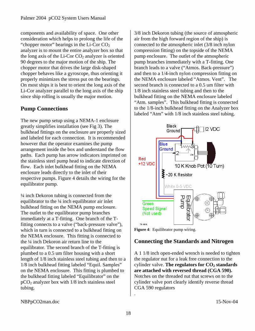
components and availability of space. One other consideration which helps to prolong the life of the “chopper motor” bearings in the Li-Cor CO2 analyzer is to mount the entire analyzer box so that the long axis of the Li-Cor CO2 analyzer is oriented 90 degrees to the major motion of the ship. The chopper motor that drives the large disk-shaped chopper behaves like a gyroscope, thus orienting it properly minimizes the stress put on the bearings. On most ships it is best to orient the long axis of the Li-Cor analyzer parallel to the long axis of the ship since ship rolling is usually the major motion. Pump Connections The new pump setup using a NEMA-1 enclosure greatly simplifies installation (see Fig 3). The bulkhead fittings on the enclosure are properly sized and labeled for each connection. It is recommended however that the operator examines the pump arrangement inside the box and understand the flow paths. Each pump has arrow indicators imprinted on the stainless steel pump head to indicate direction of flow. Each inlet bulkhead fitting on the NEMA enclosure leads directly to the inlet of their respective pumps. Figure 4 details the wiring for the equilibrator pump. ¼ inch Dekoron tubing is connected from the equilibrator to the ¼ inch equilibrator air inlet bulkhead fitting on the NEMA pump enclosure. The outlet to the equilibrator pump branches immediately at a T-fitting. One branch of the T-fitting connects to a valve (“back-pressure valve”), which in turn is connected to a bulkhead fitting on the NEMA enclosure. This fitting is connected to the ¼ inch Dekoron air return line to the equilibrator. The second branch of the T-fitting is plumbed to a 0.5 um filter housing with a short length of 1/8 inch stainless steel tubing and then to a 1/8 inch bulkhead fitting labeled “Equil. Samples” on the NEMA enclosure. This fitting is plumbed to the bulkhead fitting labeled “Equilibrator” on the pCO2 analyzer box with 1/8 inch stainless steel tubing.
3/8 inch Dekoron tubing (the source of atmospheric air from the high forward region of the ship) is connected to the atmospheric inlet (3/8 inch nylon compression fitting) on the topside of the NEMA pump enclosure. The outlet of the atmospheric pump branches immediately with a T-fitting. One branch leads to a valve (“Atmos. Back-pressure”) and then to a 1/4-inch nylon compression fitting on the NEMA enclosure labeled “Atmos. Vent”. The second branch is connected to a 0.5 um filter with 1/8 inch stainless steel tubing and then to the bulkhead fitting on the NEMA enclosure labeled “Atm. samples”. This bulkhead fitting is connected to the 1/8-inch bulkhead fitting on the Analyzer box labeled “Atm” with 1/8 inch stainless steel tubing.
Figure 4: Equilibrator pump wiring. Connecting the Standards and Nitrogen A 1 1/8 inch open-ended wrench is needed to tighten the regulator nut for a leak free connection to the cylinder valve. The regulators for CO2 standards are attached with reversed thread (CGA 590). Notches on the threaded nut that screws on to the cylinder valve port clearly identify reverse thread CGA 590 regulators .
NBPpCO2man.doc 15-Nov-04 18

Palmer 2004 pCO2 System Users Manual
Each standard gas and Nitrogen is connected to the appropriate bulkhead fitting on the analyzer box with 1/8 inch stainless steel tubing. When working with metal tubing keep dirt, debris, water and metal filings out. Filings can be flushed with a blast of nitrogen. Always use a second wrench to prevent the bulkhead fitting from turning when tightening the Swagelok nut. The nitrogen must be connected to the nitrogen bulkhead fitting (position 1). The sequence of the standards at the bulkhead fittings must be identical to their arrangement in the Setup window of the Labview program. The order in which the different standards are chosen by the program is easily determined by tracing each 1/8-inch stainless steel tube from the bulkhead fitting to the Valco multi-position selection valve. One port on the multi-position valve sits slightly closer to the driver motor, this is the outlet port of the valve where all the gases pass as they are selected when the valve is stepped in a counterclockwise fashion by the motor (as viewed from the direction opposite the micro-actuator). This port is plumbed directly to the Nafion dryer tube. The first port counterclockwise from the outlet port (“Position 1”) is for the Nitrogen standard. The remaining ports are selected sequentially in the same counterclockwise direction. See the VICI manual for more detail on the multi-position selection valve. Route the tubing from the cylinders neatly and out of the way. Secure the tubing to minimize movements and vibrations. The tubes can be bundled with wire ties to keep them from moving around. Metal tubing may develop leaks from excessive vibration or movement especially at the exits of Swagelok nuts or where the tubing is in contact with a hard edge. Leaks also tend to develop if the Swagelok nuts have been over-tightened as sometimes occurs after repeated connection and disconnection. When additional tightening fails to stop a leak the only remedy is to cut off a small amount of the tubing and re-swage it to the fitting with new ferrules. The standard for tightening Swagelok nuts (for 1/8 inch tubing) when installing
new ferrules is ¾ of a turn after the Swagelok nut is hand tight. It is best to mark the fitting and nut to ensure correct amount of tightening. Electrical Connections The analyzer system is connected to the computer through the 9 pin serial port (ASRL5 on the Keyspan USB to 4 port serial adapter). The RTD probe is wired directly to the Omegabus A/D module number 5, the last one in the chain. The computer sends data to the RVDAS system through COM4. The Optode oxygen sensor (Gould System Only) is connected to Comm1 and the oxygen output to the RVDAS is through ASRL6 on the Keyspan USB to serial port adapter. The DC power supply for the equilibrator pump and the AC power cord for the atmospheric pump is plugged into a separate power strip from the rest of the components so that they may be activated independently from the analyzer system. See Appendix 4 for additional system wiring details. Safety Precautions The open construction of the underway pCO2 system allows easy access to the plumbing, wiring and components, greatly facilitating maintenance and repair to the system. However, this easy access presents a few hazards. Observe where full 120-volt power is wired in the system. A misplaced tool or splash of water could cause personal harm or damage to the machine. A protective clear plastic cover protects the 120 Volt leads at the DC power supply but it could easily be rendered ineffective by carelessness. To minimize the risk of electrical shock, work on or around the analyzer box should only be done when the system is powered down and disconnected from the power source.
NBPpCO2man.doc 15-Nov-04
Some of the electronic components, especially the A/D modules are susceptible to damage due to static electrical discharge. Before undertaking any work near these parts be sure to discharge static and observe all standard procedures for working with sensitive electronic components.
19

Palmer 2004 pCO2 System Users Manual
Appendix 2 A Diagnostic Program A Labview diagnostic program can be initiated allowing the collection of higher temporal resolution data for diagnostics purposes by toggling the “Display Diagnostics” button in the setup window before starting the system. The measurement interval (in milliseconds) can be chosen but is defaulted to 5,000 ms (i.e. 5 seconds). This program will save a text data file in the data2 subdirectory. The upper plot on the diagnostics display is the raw millivolt output of the CO2 analyzer, the middle plot is the IR cell temperature and the lower plot is the valve position. This program is very useful for monitoring the response of the Li-Cor CO2 analyzer for instance as each different standard is cycled through. With the finer temporal resolution data it is possible to see how long it takes to purge the previous standard from the cell and whether or not a stable reading is achieved in the allotted purge time at a given flow rate. This program is intended for diagnostics purposes only and not for normal underway operation. Appendix 3 Total Carbon (tCO2) Samples Part of the underway pCO2 sampling on the RV Gould involves taking total carbon (TCO2) samples from the uncontaminated seawater system. This extra sampling coincides with that vessel’s regular Drake Passage XBT surveys. A step-by-step set of instructions is included on the data sheet with the sample bottles and is posted as well on the inside surface of the wooden lid for the sample bottle crate. The instructions are repeated here but with more elaboration. Discrete TCO2 Sampling Procedure
NBPpCO2man.doc 15-Nov-04
1) Toggle the Labview pCO2 interface to the “Discrete TCO2 Samples” window and enter the requested information. This initiates a new text data file in which a line of data from the pCO2 analyzer will be written along with each TCO2 sample collected.
2) Reduce flow through the seawater sampling tube so the bottle fills in more than 10 seconds. A slow fill ensures minimal agitation and bubbles thus preventing exchange of CO2 with the ambient lab air. This can be done well ahead of time and it is best to simply leave this water flowing for the duration of the tCO2 sampling transect. 3) Wait for the green light indicating equilibrator samples are being run, toggle the discrete sample time mark button and begin taking the sample. Toggling the button will write a sample identifier to the pCO2 data file and also copy that line of data to the tCO2 data file initiated in step 1 above. 4) Crimp the sampling tube and insert into sample bottle all the way to the bottom, release crimp and let bottle fill slowly without forming bubbles. Dump the bottle twice. Crimping the tube diminishes agitation and CO2 exchange. Dumping 2 times ensures extraneous carbon contamination in the bottle has been removed. 5) Fill a third time allowing at least one full volume of water to overflow. This step will help remove bubbles and flush water out of the bottle that had contact with ambient air. 6) Crimp the tube and pull it out of the bottle leaving a small space that extends just below the bottleneck. If the tube was inserted all the way to the bottom of the bottle and flow was completely stopped by crimping the tube then the exact amount of air space will be left in the bottle. 7) Using the preset dispensing pipette add 100 µL of saturated HgCl solution to sample. Grease the frosted region of the stopper with two or three thin vertical stripes of silicon grease spaced evenly around the stopper. Insert the stopper firmly with a twisting motion. Note: The proper amount of grease and insertion force will cause the frosted ground glass surfaces of the bottle and stopper to become completely clear. A good seal with the silicon grease is important to prevent CO2 exchange. Invert the bottle several times to mix the HgCl preservative. 8) Label the pre-numbered sample bottle with Cruise ID, GMT date and GMT time. Fill out the data sheet with GMT date, GMT time, Latitude, Longitude, Sea Surface Temperature (SST), Sea
20
Palmer 2004 pCO2 System Users Manual
Surface Salinity (SSS), pCO2 and Flourometer. All of this information is displayed on the RVDAS data screen. 9) Wrap 2 elastic bands oriented at 90 degrees to each other length wise around the bottle and stopper. Secure the rubber bands with two complete wraps of electrical tape at the neck and two complete wraps near the bottom of bottle (fig. 1c). The tapered glass stoppers will pop out during shipping if they are not secured with rubber bands and tape!! 10) Return the bottle to box with the same sample number on it. This number also should correspond to the sample number on the data sheet. Sample Shipping Instructions: Make a copy of the completed data sheet and store the copy in the pCO2 binder. Include the original data sheet in the sample bottle crate with the samples to be shipped back to Lamont Doherty Earth Observatory. Use zip ties or strapping tape to secure the plywood lid on the sample bottle crate. Place the crate in the lidded cardboard box and fill extra space with bubble wrap or other suitable packing material. Tape box with strapping tape. Label for COMAIR shipping, Do Not Freeze, Fragile. The address is in the Cargo Data Base, under Project 214 and should read as follows: Tim Newberger Lamont Doherty Earth Observatory 61 Route 9W, P.O. Box 1000 Palisades, NY 10964 Room 105, Geoscience Phone: (845) 365-8790 [email protected]
NBPpCO2man.doc 15-Nov-04 21

Palmer 2004 pCO2 System Users Manual
Appendix 4: System Wiring Valco valve Controller Wiring *Thicker wires spliced onto ribbon wires Blue** is separate wire, remaining wires bundled.
A/D Module *Spliced Ribbon Controller Module # Pin # Color Wire Pin #
1 3 White Brown 1 Red 2 1 5 Red Orange 3 Yellow 4 2 5 Green Green 5 Blue 6 Violet 7 5 5 Violet Grey 8 White 9 1 10 Black Black 10 Brown 11 N/A N/A Brown Red 12 Orange 13 3 4 Tan Yellow 14 Green 15 2 4 Orange Blue 16 4 4 Grey Violet 17 1 4 Pink Grey 18 White 19 Black 20 Brown 21 3 5 Blue** Red 22 Orange 23 3 3 Yellow Yellow 24 4 3 Blue Green 25 Blue 26 Serial Cable Wiring
A/D Module Wire Serial Module # Pin # Color Pin #
5 10 White 1 5 7 Green 2 1 8 Black 3 1 10 Red 5
Flow Meter Wiring
A/D Module Wire Serial Module # Pin # Color Pin #
4 1 Green 2
4 2 White 3
4 9 Red 4
4 10 Black 5 Barometer Wiring
A/D Module Wire Module # Pin # Color
3 1 Green 3 2 White Li-Cor CO2 Analyzer Wiring
A/D Module Wire Li-Cor pin number Module # Pin # Color
1 1 Red 1 1 2 Black 2 2 1 Green 7 2 2 White 8 RTD wiring
A/D Module Wire Module # Pin # Color
5 1 White 5 2 Black 5 3,4 Red
NBPpCO2man.doc 15-Nov-04 22

Palmer 2004 pCO2 System Users Manual
Appendix 5: A/D Module Configuration Module #1 Setup code = 31020580 Read IR Type = 1141 Byte Hex Bit # Comments 76543210 1 31 00110001 Address = 1 2 02 00000010 No linefeed, no parity, Baud 9600 3 05 00000101 Alarms off, Echo on, 2 byte time delay 4 80 10000000 XXXXX.X displayed digits, 1 decimal place Module #2 Setup code = 320205C0 Read Cell T Type = 1131 Byte Hex Bit # Comments 76543210 1 32 00110010 Address = 2 2 02 00000010 No linefeed, no parity, Baud 9600 3 05 00000101 Alarms off, Echo on, 2 byte time delay 4 C0 11000000 XXXXX.XX displayed digits, 2 decimal places Module #3 Setup code = 330205C0 Read Baro. Type = 1131 Byte Hex Bit # Comments 76543210 1 33 00110011 Address = 3 2 02 00000010 No linefeed, no parity, Baud 9600 3 05 00000101 Alarms off, Echo on, 2 byte time delay 4 C0 11000000 XXXXX.XX displayed digits, 2 decimal places Module #4 Setup code = 340205C0 Read Flow Type = 1131 Byte Hex Bit # Comments 76543210 1 34 00110100 Address = 4 2 02 00000010 No linefeed, no parity, Baud 9600 3 05 00000101 Alarms off, Echo on, 2 byte time delay 4 C0 11000000 XXXXX.XX displayed digits, 2 decimal places Module #5 Setup code = 35020580 Read Eq. T. Type = 1411 Byte Hex Bit # Comments RTD 76543210 1 35 00110101 Address = 5 2 02 00000010 No linefeed, no parity, Baud 9600 3 05 00000101 Alarms. off, C, Echo on, 2 byte time delay 4 80 10000000 XXXXX.X displayed digits, 1 decimal place
NBPpCO2man.doc 15-Nov-04 23

Palmer 2004 pCO2 System Users Manual
NBPpCO2man.doc 15-Nov-04 1