NATIONAL COOPERATIVE HIGHWAY SYNTHESIS...
48
92 NATIONAL COOPERATIVE HIGHWAY RESEARCH PROGRAM SYNTHESIS OF HIGHWAY PRACTICE 92 MINIMIZING REFLECTION CRACKING OF PAVEMENT OVERLAYS 91 TRANSPORTATION RESEARCH BOARD NATIONAL RESEARCH COUNCIL
Transcript of NATIONAL COOPERATIVE HIGHWAY SYNTHESIS...

92
NATIONAL COOPERATIVE HIGHWAY RESEARCH PROGRAM SYNTHESIS OF HIGHWAY PRACTICE 92
MINIMIZING REFLECTION CRACKING OF PAVEMENT OVERLAYS
91
TRANSPORTATION RESEARCH BOARD NATIONAL RESEARCH COUNCIL

TRANSPORTATION RESEARCH BOARD EXECUTIVE COMMITTEE 1982
Officers
Chairman
DARRELL V MANNING, Director Idaho Transportation Department
Vice Chairman
LAWRENCE D. DAHMS, Executive Director, Metropolitan Transportation Commission, San Francisco Bay Area
Secretary
THOMAS B. DEEN, Executive Director, Transportation Research Board
Members
RAY A. BARNI-JART, Federal Highway Administrator, U.S. Department of Transportation (cx officio)
FRANCIS B. FRANCOIS, Executive Director, American Association of State Highway and Transportation Officials (cx officio)
WILLIAM J. HARRIS, JR., Vice President for Research and Test Department, Association of American Railroads (cx officio)
J. LYNN HELMS, Federal Aviation Administrator, U.S. Department of Transportation (cx officio)
THOMAS D. LARSON, Secretary. Pennsylvania Department of Transportation (cx officio, Past Chairman 1981)
RAYMOND A. PECK, JR., National Highway Traffic Safety Administrator, U.S. Department of Transportation (cx officio)
ARTHUR E. TEELE, JR., Urban Mass Transportation Administrator, U.S. Department of Transportation (cx officio)
CHARLEY V. WOOTAN, Director, Texas Transportation institute. Texas A&M University (cx officio, Past Chairman 1980)
GEORGE J. BEAN, Director of Aviation, Hillsborough County (Florida) Aviation Authority
JOHN R. BORCHERT, Professor, Department of Geography. University of Minnesota
RICHARD P. BRAUN, Commissioner, Minnesota Department of Transportation
ARTHUR J. BRUEN, JR., Vice President, Continental Illinois National Bank and Trust Company of Chicago
JOSEPH M. CLAPP, Senior Vice President, Roadway Express, Inc.
ALAN G. DUSTIN, President and Chief Executive Officer, Boston and Maine Corporation
ROBERT E. FARRIS, Commissioner, Tennessee Department of Transportation
ADRIANA GIANTURCO. Director, California Department of Transportation
JACK R. GILSTRAP, Executive Vice President, American Public Transit Association
MARK G. GOODE, Engineer-Director, Texas State Department of Highways and Public Transportation
WILLIAM C. 1-IENNESSY, Commissioner, New York State Department of Transportation
LESTER A. HOEL, Chairman, Department of Civil Engineering. University of Virginia
MARVIN L. MANHEIM, Professor, Department of Civil Engineering, Massachusetts Institute of Technology
FUJIO MATSUDA, President, University of Hawaii
DANIEL T. MURPHY, County Executive, Oakland County Courthouse, Michigan
ROLAND A. OUELLET'FE, Director of Transportation Affairs, General Motors Corporation
RICHARD S. PAGE, General Manager, Washington (D.C.) Metropolitan Area Transit Authority
MILTON PIKARSKY, Director of Transportation Research, Illinois institute of Technology
GUERDON S. SINES, Vice President, information and Control Systems, Missouri Pacific Railroad
JOHN E. STEINER, Vice President. Corporate Product Development, The Boeing Company
RICHARD A. WARD, Director-Chief Engineer. Oklahoma Department of Transportation
NATIONAL COOPERATIVE HIGHWAY RESEARCH PROGRAM
Transportation Research Board Executive Committee Subcommittee for NCHRP
DARRELL V MANNING, Idaho Transp. Dept. (Chairman) LA WRENCE D. DAH MS. Metropolitan Transportation Commission
WILLIAM J. HARRIS, JR., Association of American Railroads
ARTHUR TEELE, JR., Urban Mass Transportation Administration
Fü'ld of Special Projects
Project ('omn,ittee SP 20-5
RAY R. BIEGE, JR.. Consultant (Chairman)
VERDI ADAM, Louisiana Dept. of Transp. and Development
ROBERT N. BOTHMAN, Oregon Dept. of Transportation
JACK H. DILLARD, Virginia Hwy. and Transp. Research Council
JACK FRIEDENRICH, New Jersey Dept. of Transportation
DAVID GEDNEY, De Leuw, Cather and Company
SAMFORD P. LAHUE, Federal Highway Administration
BRYANT MATHER. USAE Waterways Experiment Station
THOMAS H. MAY, Pennsylvania Dept. of Transportation
THEODORE F. MORF, Consultant
EDWARD A. MUELLER, Jacksonville Transp. Authority
ROBERT J. BETSOLD, Federal Highway Administration
K. B. JOHNS, Transportation Research Board
JACK R. GILSTRAP, American Public Transit Association
RICHARD S. PAGE, Washington Metropolitan Area Transit Authority
THOMAS D. LARSON, Pennsylvania Dept. of Transportation
THOMAS B. DEEN, Transportation Research Board
Program Staff
KRIEGER W. HENDERSON, JR., Director, Cooperative Research Programs
LOUIS M. MACGREGOR, Administrative Engineer
CRAWFORD F. JENCKS, Projects Engineer
R. IAN KINGHAM, Projects Engineer
ROBERT J. REILLY, Projects Engineer
HARRY A. SMITH, Projects Engineer
ROBERT E. SPICHER, Projects Engineer
HELEN MACK, Editor
TRB Stafffi,r NCHRP Project 20-5
PAUL E. IRICK, Assistant Director for Special Technical Activities Division
THOMAS L. COPAS, Special Projects Engineer
HERBERT A. PENNOCK, Special Projects Engineer
NANCY A. ACKERMAN. Editor

NATIONAL COOPERATIVE HIGHWAY RESEARCH PROGRAM SYNTHESIS OF HIGHWAY PRACTICE 92
MINIMIZING REFLECTION CRACKING OF PAVEMENT OVERLAYS
GEORGE SHERMAN
Fair Oaks, California
Topic Panel
C. S. HUGHES, lit, Virginia Highway and Transportation Research Council
RICHARD W. KINCHEN, Louisiana Department of Transportation
and Development
EDWIN C. LOKKEN, Portland Cement Association
VAUGHN MARKER, The Asphalt Institute
DONALD R. SCHWARTZ, Illinois Department of Transportation
WILLIAM A. WOOD, Federal Highway Administration
RESEARCH SPONSORED BY THE AMERICAN ASSOCIATION OF STATE HIGHWAY AND TRANSPORTATION OFFICIALS IN COOPERATION WITH THE FEDERAL HIGHWAY ADMINISTRATION
TRANSPORTATION RESEARCH BOARD NATIONAL RESEARCH COUNCIL
WASHINGTON, D.C. SEPTEMBER 1982
NATIONAL COOPERATIVE HIGHWAY RESEARCH PROGRAM NCHRP SYNTHESIS 92
Systematic, well-designed research provides the most effec-tive approach to the solution of many problems facing high-way administrators and engineers. Often, highway problems are of local interest and can best be studied by highway departments individually or in cooperation with their state universities and others. However, the accelerating growth of highway transportation develops increasingly complex prob-lems of wide interest to highway authorities. These problems are best studied through a coordinated program of coopera-tive research.
In recognition of these needs, the highway administrators of the American Association of State Highway and Transpor-tation Officials initiated in 1962 an objective national highway research program employing modern scientific tech-niques. This program is supported on a continuing basis by funds from participating member states of the Association and it receives the full cooperation and support of the Federal Highway Administration, United States Department of Transportation.
The Transportation Research Board of the National Re-search Council was requested by the Association to ad-minister the research program because of the Board's recog-nized objectivity and understanding of modern research practices. The Board is uniquely suited for this purpose as: it maintains an extensive committee structure from which authorities on any highway transportation subject may be drawn; it possesses avenues of commumcations and cooper-ation with federal, state, and local governmental agencies, universities, and industry; its relationship to its parent orga-nization, the National Academy of Sciences, a private, non-profit institution, is an insurance of objectivity; it maintains a full-time research correlation staff of specialists in highway transportation matters to bring the findings of research directly to those who are in a position to use them.
The program is developed on the basis of research needs identified by chief administrators of the highway and trans-portation departments and by committees of AASHTO. Each year, specific areas of research needs to be included in the program are proposed to the Academy and the Board by the American Association of State Highway and Transporta-tion Officials. Research projects to fulfill these needs are defined by the Board, and qualified research agencies are selected from those that have submitted proposals. Adminis-tration and surveillance of research contracts are the respon-sibilities of the Academy and its Transportation Research Board.
The needs for highway research are many, and the Na-tional Cooperative Highway Research Program can make significant contributions to the solution of highway transpor-tation problems of mutual concern to many responsible groups. The program, however, is intended to complement rather than to substitute for or duplicate other highway re-search programs.
Project 20-5 FY 1979 (Topic 11-04)
ISSN 0547-5570
ISBN 0-309-03453-1
Library of Congress Catalog Card No. 82-083896
Price: $6.80
Subject Areas Pavement Design and Performance Bituminous Materials and Mixes Maintenance
Mode Highway Transportation
NOTICE
The project that is the subject of this report was a part of the National Cooper-ative Highway Research Program conducted by the Transportation Research Board with the approval of the Governing Board of the National Research Council, acting in behalf of the National Academy of Sciences. Such approval reflects the Governing Board's judgment that the program concerned is of national importance and appropriate with respect to both the purposes and resources of the National Research Council.
The members of the technical committee selected to monitor this project and to review this report were chosen for recognized scholarly competence and with due consideration for the balance of disciplines appropriate to the project. The opinions and conclusions expressed or implied are those of the research agency that performed the research, and, while they have been accepted as appropriate by the technical committee, they are not necessarily those of the Transportation Research Board, the National Research Council, the National Academy of Sciences, or the program sponsors.
Each report is reviewed and processed according to procedures established and monitored by the Report Review Committee of the National Academy of Sciences. Distribution of the report is approved by the President of the Acad-emy upon satisfactory completion of the review process.
The National Research Council was established by the National Academy of Sciences in 1916 to associate the broad community of science and tech-nology with the Academy's purposes of furthering knowledge and of advising the Federal Government. The Council operates in accordance with general policies determined by the Academy under the authority of its congressional charter of 1863, which establishes the Academy as a private, nonprofit, self-governing membership corporation. The Council has become the principal operating agency of both the National Academy of Sciences and the National Academy of Engineering in the conduct of their servives to the government, the public, and the scientific and engineering communities. It is administered jointly by both Academies and the Institute of Medicine. The National Acad-emy of Engineering and the Institute of Medicine were established in 1964 and 1970, respectively, under the charter of the National Academy of Sciences.
The Transportation Research Board evolved from the 54-year-old Highway Research Board. The TRB incorporates all former HRB activities and also performs additional functions under a broader scope involving all modes of transportation and the interactions of transportation with society.
Published reports of the
NATIONAL COOPERATIVE HIGHWAY RESEARCH PROGRAM
are available from:
Transportation Research Board National Academy of Sciences 2101 Constitution Avenue, N.W. Washington, D.C. 20418
Printed in the United States of America.

PREFACE A vast storehouse of information exists on nearly every subject of concern to highway administrators and engineers. Much of this information has resulted from both research and the successful application of solutions to the problems faced by practitioners in their daily work. Because previously there has been no systematic means for compiling such useful information and making it available to the entire highway community, the American Association of State Highway and Transporta-tion Officials has, through the mechanism of the National Cooperative Highway Research Program, authorized the Transportation Research Board to undertake a continuing project to search out and synthesize useful knowledge from all avail-able sources and to prepare documented reports on current practices in the subject areas of concern.
This synthesis series reports on various practices, making specific recommen-dations where appropriate but without the detailed directions usually found in handbooks or design manuals. Nonetheless, these documents can serve similar purposes, for each is a compendium of the best knowledge available on those measures found to be the most successful in resolving specific problems. The extent to which these reports are useful will be tempered by the user's knowledge and experience in the particular problem area.
FOREWORD This synthesis will be of special interest to pavement designers, materials special-
By Staff ists, maintenance engineers, and others concerned with the performance of
Transportation pavement overlays. Methods are presented for reducing reflection cracking in
Research Board overlays.
Administrators, engineers, and researchers are continually faced with highway problems on which much information exists, either in the form of reports or in terms of undocumented experience and practice. Unfortunately, this information often is scattered and unevaluated, and, as a consequence, in seeking solutions, full information on what has been learned about a problem frequently is not assembled. Costly research findings may go unused, valuable experience may be overlooked, and full consideration may not be given to available practices for solving or alleviating the problem. In an effort to correct this situation, a continu-ing NCHRP project, carried out by the Transportation Research Board as the research agency, has the objective of reporting on common highway problems and synthesizing available information. The synthesis reports from this endeavor con-stitute an NCHRP publication series in which various forms of relevant informa-tion are assembled into single concise documents pertaining to specific highway problems or sets of closely related problems.

Reflection cracks can shorten the service life of overlays on both asphalt and portland cement concrete pavements. This report of the Transportation Research Board contains a discussion of the causes of reflection cracking and provides guidance on the methods of preventing this problem.
To develop this synthesis in a comprehensive manner and to ensure inclusion of significant knowledge, the Board analyzed available information assembled from numerous sources, including a large number of state highway and transpor-tation departments. A topic panel of experts in the subject area was established to guide the researcher in organizing and evaluating the collected data, and to review the final synthesis report.
This synthesis is an immediately useful document that records practices that were acceptable within the limitations of the knowledge available at the time of its preparation. As the processes of advancement continue, new knowledge can be expected to be added to that now at hand.

CONTENTS
1 SUMMARY
3 CHAPTER ONE INTRODUCTION
Mechanics of Reflection Cracking, 3 Background, 4 NEEP-10 Project, 5 Purpose of Synthesis, 5 Factors Affecting the Results of Field Experiments, 5
7 CHAPTER TWO ASPHALT CONCRETE OVERLAYS
Thickness of Overlay, 7 Viscosity of Asphalt, 8 Effect of Additives, 8
9 CHAPTER THREE TREATMENT OF EXISTING PAVEMENTS
Seal Coats as a Surface Application on AC Pavement, 9 Rejuvenating Agents, 10 Heater-Scarifier Process, 10 Crack Filling—AC and PCC, 10 Stabilizing PCC Slabs by Subsealing, 11 Stabilizing PCC Slabs by Breaking, 11 Pavement Recycling, 12
12 CHAPTER FOUR STRESS-RELIEVING INTERLAYERS
Asphalt-Rubber Interlayers, 12 Prefabricated Fabric Membrane Strips, 13 Fabric Interlayers, 13 Low-Viscosity AC Interlayers Over AC Pavement, 17 Open-Graded AC Base Layers, 17 Open-Graded AC Layers 1.5 in. (38 mm) or Less in
Thickness, 18 Gravel or Crushed Rock Interlayers, 18
19 CHAPTER FIVE PORTLAND CEMENT CONCRETE OVERLAYS
20 CHAPTER SIX THEORETICAL APPROACHES
24 CHAPTER SEVEN CONCLUSIONS AND RECOMMENDATIONS
24 REFERENCES
28 APPENDIX SUMMARY OF EXPERIMENTAL OVERLAY PROJECTS IN
SELECTED STATES

ACKNOWLEDGMENTS
This synthesis was completed by the Transportation Research Board under the supervision of Paul E. kick, Assistant Director for Special Technical Activities Division. The Principal Investigators responsible for conduct of the synthesis were Thomas L. Copas and Herbert A. Pennock, Special Projects Engineers. This synthesis was edited by Nancy A. Ackerman.
Special appreciation is expressed to George Sherman, Fair Oaks, California, who was responsible for the collection of data and the preparation of the report.
Valuable assistance in the preparation of this synthesis was pro-vided by the Topic Panel, consisting of C. S. Hughes, III, Senior Research Scientist, Virginia Highway and Transportation Research Council; Richard W. Kinchen, Data Analysis Research Engineer, Louisiana Department of Transportation and Development; Edwin C. Lokken, Principal Highway Engineer, Portland Cement Associa-tion; Vaughn Marker, Chief Engineer, The Asphalt Institute; Donald R. Schwartz, Engineer of Physical Research, Illinois Department of Transportation; and William A. Wood, Highway Engineer, Federal Highway Administration.
Adrian G. Clary, Engineer of Maintenance, and William G. Gun-derman, Engineer of Materials and Construction, of the Transporta-tion Research Board, assisted the NCHRP Project 20-5 Staff and the Topic Panel.
Information on current practice was provided by many highway and transportation agencies. Their cooperatiOn and assistance were most helpful.

MINIMIZING REFLECTION CRACKING OF PAVEMENT OVERLAYS
SUMMARY Reflection cracks are fractures in a pavement overlay that are the result of, and reflect, the crack or joint pattern in the underlying layer. Reflection cracks can cause early deterioration of an overlay, thereby increasing maintenance costs and decreasing the useful life of the overlay.
Reflection cracks are generally assumed to be caused by horizontal and verti-cal movements of pavement that is being resurfaced. There has been much field experimentation since 1932; however, it is only recently that theoretical studies of reflection cracking have been initiated. The National Experimental and Evaluation Program for Reducing Reflection Cracking in Bituminous Overlays (the NEEP-lO project) has been one of the most extensive projects for testing methods to reduce reflection cracking.
Methods that have been used to minimize reflection cracking of asphalt concrete overlays include (a) greater thickness of overlay, (b) changes in the viscosity of the asphalt, (c) additives incorporated into the asphalt concrete mix-ture, (d) treatments to the existing pavement before overlaying (seal coats, re-juvenators, heater-scarifying, crack filling, pavement breaking, stabilization, and recycling), and (e) stress-relieving interlayers (asphalt-rubber, membranes, fabrics, low-viscosity asphalt concrete, open-graded asphalt concrete, and aggregate). Results of various tests using these methods are presented in the synthesis.
Portland cement concrete overlays that are bonded or partially bonded to the existing pavement have joints that match the old joints; thus reflection cracking is not a problem. Unbonded portland cement concrete overlays are separated from the old pavement by an interlayer and cracks do not reflect through.
Theoretical approaches to reflection crackiig, based on fracture mechanics principles, have provided methods for calculating the maximum stress or strain in an overlay in order to indicate whether or not reflection cracking will occur.
Conclusions of this synthesis include:
Overlay systems that have retarded reflection cracking of asphalt concrete overlays on old asphalt concrete pavements are low-viscosity asphalt (in the overlay or as an interlayer), heater-scarifier remix of the old surface, asphalt-rubber interlayer, certain fabrics (for other than thermally induced cracks), and overlays thicker than 2 in. (50 mm).
Overlay systems that have retarded reflection cracking of asphalt concrete overlays on old portland cement concrete pavements are 6-in. (150-mm) thick overlays where vertical movement is not excessive, and stress-relieving layers

such as prefabricated fabric membrane strips or a 3.5-in. (90-mm) layer of open-
graded asphalt concrete base. For bonded and partially bonded portland cement concrete overlays, new
joints should be placed over old joints; unbonded oyerlays do not require matching
joints. Additional research and field testing are necessary to verify theoretical
approaches as practical design systems.
CHAPTER ONE
INTRODUCTION
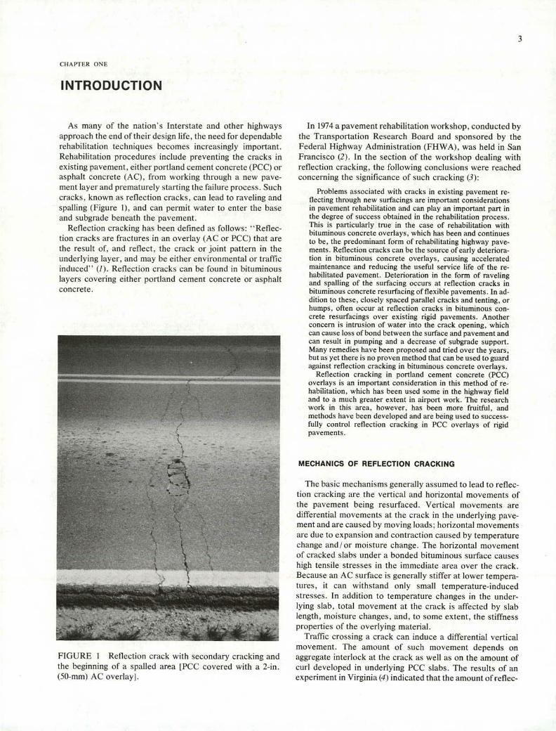
As many of the nation's Interstate and other highways approach the end of their design life, the need for dependable rehabilitation techniques becomes increasingly important. Rehabilitation procedures include preventing the cracks in existing pavement, either portland cement concrete (PCC) or asphalt concrete (AC). from working through a new pave-ment layer and prematurely starting the failure process. Such cracks, known as reflection cracks, can lead to raveling and spalling (Figure 1), and can permit water to enter the base and subgrade beneath the pavement.
Reflection cracking has been defined as follows: 'Reflec-tion cracks are fractures in an overlay (AC or PCC) that are the result of, and reflect, the crack or joint pattern in the underlying layer, and may be either environmental or traffic induced" (I). Reflection cracks can be found in bituminous layers covering either portland cement concrete or asphalt concrete.
:
"I .
H
FIGURE I Reflection crack with secondary cracking and the beginning of a spalled area [PCC covered with a 2-in. (50-mm) AC overlay].
In 1974 a pavement rehabilitation workshop, conducted by the Transportation Research Board and sponsored by the Federal Highway Administration (FHWA), was held in San Francisco (2). In the section of the workshop dealing with reflection cracking, the following conclusions were reached concerning the significance of such cracking (3):
Problems associated with cracks in existing pavement re-flecting through new surfacings are important considerations in pavement rehabilitation and can play an important part in the degree of success obtained in the rehabilitation process. This is particularly true in the case of rehabilitation with bituminous concrete overlays, which has been and continues to be, the predominant form of rehabilitating highway pave-ments. Reflection cracks can be the source of early deteriora-tion in bituminous concrete overlays, causing accelerated maintenance and reducing the useful service life of the re-habilitated pavement. Deterioration in the form of raveling and spalling of the surfacing occurs at reflection cracks in bituminous concrete resurfacing of flexible pavements. In ad-dition to these, closely spaced parallel cracks and tenting, or humps, often occur at reflection cracks in bituminous con-crete resurfacings over existing rigid pavements. Another concern is intrusion of water into the crack opening, which can cause loss of bond between the surface and pavement and can result in pumping and a decrease of subgrade support. Many remedies have been proposed and tried over the years, but as yet there is no proven method that can be used to guard against reflection cracking in bituminous concrete overlays.
Reflection cracking in portland cement concrete (PCC) overlays is an important consideration in this method of re-habilitation, which has been used some in the highway field and to a much greater extent in airport work. The research work in this area, however, has been more fruitful, and methods have been developed and are being used to success-fully control reflection cracking in PCC overlays of rigid pavements.
MECHANICS OF REFLECTION CRACKING
The basic mechanisms generally assumed to lead to reflec-tion cracking are the vertical and horizontal movements of the pavement being resurfaced. Vertical movements are differential movements at the crack in the underlying pave-ment and are caused by moving loads: horizontal movements are due to expansion and contraction caused by temperature change and/ moisture change. The horizontal movement of cracked slabs under a bonded bituminous surface causes high tensile stresses in the immediate area over the crack. Because an AC surface is generally stiffer at lower tempera-tures, it can withstand only small temperature-induced stresses. In addition to temperature changes in the under-lying slab, total movement at the crack is affected by slab length, moisture changes, and, to some extent, the stiffness properties of the overlying material.
Traffic crossing a crack can induce a differential vertical movement. The amount of such movement depends on aggregate interlock at the crack as well as on the amount of curl developed in underlying PCC slabs. The results of an experiment in Virginia (4) indicated that the amount ofreflec-

tion cracking in a particular PCC roadway depended on the amount of differential movement as determined by deflection measurements.
BACKGROUND
Until the 1970's, most of the field research on reduction of reflection cracking was based on (a) increased thickness, (b) cushion courses, (c) treatment of existing slabs, or (d) reinforcement of AC surface. One of the first AC overlays of PCC pavement was the placement of a thin resurfacing layer [1 to 1.5 in. (25 to 38 mm) thick at the edges and 3 in. (75 mm) in the center] on Union Street in Schenectady, New York, in 1909 (5). In 1930 the Portland Cement Association reviewed the performance of 200 miles (320 km) of PCC overlays placed in California between 1919 and 1930 (5), and reported that, depending on traffic and deterioration of the roadway, 4 or 5 in. (100 or 125 mm) of PCC resurfacing was required in order to prevent reflection cracking.
The problem of reflection cracking is not new and has been under study since 1932. In that year, the Highway Research Board conducted a symposium on "Resurfacing Portland Cement Concrete Pavements," which included reflection cracking experiences. Experience of that period was sum-marized in papers by Fleming (5) and Gray and Martin (6). Since then, much field experimentation has been done, but only in recent years have theoretical approaches been studied.
Bone et al. (7) concluded in 1954 that the horizontal move- ment of slabs was the predominant factor in reflection crack-ing. They found a seasonal length variation of 0.10 to 0.18in. (2.5 to 4.6 mm) per 57 ft (17 m) (at the time of the experi-ments this was the distance between expansion joints in Massachusetts). The results of their work also indicated that the AC surfacing used at that time, when made into test specimens 13 in. (330 mm) in length, would not tolerate strains in excess of 0.05 in. (1.3 mm) without cracking. The results were verified by field measurements, which revealed that cracking had occurred in nearly every case where the surfacing had stretched more than 0.05 in. in 13 in.
The first systematic field study to evaluate factors affect-ing AC resurfacing of concrete pavements was reported in 1955 by Crump and Bone (8). The results of their study of 25 test sections, each 1000 ft (305 m) long, led to two significant conclusions (8):
The successive record of various sections showed a definite progressing of reflection cracking in the early years. Different types of cracking develop at different rates but all types increase with each additional climatic cycle. For instance, by the third year many pavements had cracks over more than 75% of the length of the transverse joint. A few reached 95 to 100% in three or four years. Successive surveys, then, show a progressive growth of crack width after each annual temperature cycle rather than an in-crease in length of cracking. Resurfacings laid in the fall do not usually crack until their second winter. Those laid in the spring or summer almost always begin to crack during the first winter. After about 2 years the cracking was about equal on both types.
In 1963 Vicelja (9) reported to the Association of Asphalt Paving Technologists the results of a 4-yr study in Los Angeles of the effectiveness of expanded wire-mesh rein-
forcement, aluminum foil, wax paper, and stonedust in breaking the bond over existing PCC shrinkage cracks. Of particular interest was the use of an 18-in. (450-mm) swath of stonedust to reduce bond at the crack. This treatment was successful in retarding reflection cracking. Kanarowski (10) also summarized the performance of bond breakers, includ-ing stonedust, used by nine agencies. Two agencies reported the process as very good to excellent; the others reported the process to be ineffective.
Another early attempt to reduce reflection cracking was the use of wire reinforcement in the asphalt resurfacing layer. The ineffectiveness of this treatment was reviewed in 1968 by Kanarowski (10) who summarized the experiences of 20 agencies in using wire reinforcement in AC overlays placed on PCC. The author found that performance ranged from poor to excellent, with Illinois reporting good performance after 11.5 yr of service. He concluded that the method of placing the welded wire fabric was an important factor in the performance of the material. Recent literature does not report the use of wire reinforcing in AC overlays. It appar-ently is no longer (or rarely) used because of unsatisfactory experience or excessive cost.
A method consisting of breaking old concrete pavement into smaller segments using heavy pneumatic rollers of 50+ tons (45+ mg) was employed to reduce the effect of expan-sion and contraction of the concrete slab. Kanarowski (10), in summarizing the experiences with this method, reported that all five states reporting apparently had success in retard-ing reflection cracking using heavy rollers to break and seat the PCC pavement. Reported results ranged from good to excellent for resurfaced pavements 5 to 10 yr old.
An attempt in Illinois to apply a systematic approach to the design of AC overlays and to include a factor for reflection cracking was reported by Elliott (11) in 1971. The study results indicated that the AASHTO present serviceability index (PSI) equation for flexible pavements was applicable for measuring performance of resurfaced pavements if the cracking term was adjusted. Therefore modifications were made to include a cracking term similar to that used in the rigid pavement PSI equation. The formula developed by Illinois is as follows:
PSI = 10.91 - 3.90 log RI - 0.01 (C + p)½ - 1.38 RD 2
- 0.09
where
RI = roughness index measured by Illinois roadmeter, C = measure of alligator cracking, P = measure of patching,
C' = measure of reflective cracking, and RD = measure of rut depth.
Nomographs have been constructed to determine the struc-tural number (SN ) of the road. These nomographs use terminal PSI values of 2.0 and 2.5, design traffic loading [18 kip (80 kN) equivalent axle loadings over the design period], and CBR of the underlying soil. The required thick-ness of resurfacing can then be determined using the thickness of the existing pavement components. The thick-ness (D ,) of the first resurfacing is determined by the equation:

DF= SNR — 0.26D c 0.40
where
D c = thickness of PCC pavement, and SN R = structural member.
For the second resurfacing the thickness (D) is determined by the equation:
Ds - SN R (0.25 D F 0.17 D
- 0.40
The limitations placed on the design system are a minimum thickness of 3 in. (75 mm) for primary and Interstate roads, and 2.5 and 1.5 in. (64 and 38 mm) for roads of lesser traffic or importance. The reason for the minimum is that a degree of smoothness is required and Illinois contends that two-course AC construction is required to obtain this riding quality.
In 1956 Roggeveen and Tons (12) reported on experiments with three rubber additives:
Emulsified rubber asphalt. Five percent (of the weight of final asphalt content) of rubber latex was added and mixed with heated aggregate.
CRS synthetic rubber. A powder with 100 percent pass-ing No. 20 (850 sm) sieve was cooked into the asphalt at 225° F (107° C) in the amount of 7.5 percent by weight.
Natural rubber crumbs. Crumbs were added directly into the pugmill in the amount of approximately 7.5 percent by weight of asphalt in the top course and 5.75 percent in the binder course.
Roggeveen and Tons concluded that 80 percent of the total transverse cracks reflected through in 4 yr and 90 percent after 6 yr whether or not rubber additives were added to the asphalt.
A similar study conducted by the Road Research Labora-tory in England (13) also showed that small percentages of rubber in asphalt concrete do not prevent reflection cracking.
Experience in California reported by Skog and Munday in 1966 (14) showed that a rubber additive did not reduce re-flective cracking. In this case, 4 percent rubber solids (styrene-butadiene latex) was added to the mix. Cracks began to appear after 2 yr, whereas the control section had cracks within 10 months. Ultimately, however, the rubber-ized section cracked to a greater degree than the control. It was pointed out in the report that the properties of the rubber asphalt are influenced by the properties of the base asphalt and the type of rubber.
2. Treatments limited to the following except when ap-proved by the Office of Engineering and Operations:
Application of Reclamite or other rejUvenating agents either sprayed on the existing pavement or, if warranted, heating and scarifying the surface before applying the rejuvenating agent and overlay. Use of Structofors, a proprietary synthetic fabric. Use of Petromat, a nonwoven polypropylene mat material. Placement of the so-called "plant-mix seal" or other special plant-mix before placement of the remaining overlay. Placement of an asphalt emulsion seal before place-ment of the overlay.
3. Control sections using the state's normal construction. 4. A condition survey and structural analysis for the exist-
ing pavement and a structural analysis for the various sec-tions of the new and total pavement structure. A detailed crack condition survey of each test area was required as was a detailed crack condition survey for the existing pavement where the normal nontest overlay was to be placed.
5. Projects that permit designs as nearly uniform as possible.
6. Evaluation period to be concluded within 2 yr (addi-tional time may be warranted).
7. Approval for tests on the Interstate system under cer-tain conditions.
8. Comparison of the performance and cost effectiveness of the individual experimental overlay sections and the state's normal overlay section.
Supplemental memoranda issued on October 13, 1970, and July 15, 1971, include the following items:
Use of Petroset AT Geotechnic Emulsion for rubberiz-ing asphalt pavements.
Use of a Strain Relieving Layer (SRI) (15).
PURPOSE OF SYNTHESIS
Since the issuance of the 1970 NEEP-10 memorandum, much experimentation in reducing reflection cracking has been carried out, including work conducted by states, coun-ties, and cities. The purpose of this synthesis is to report on the findings of many of the field tests as well as on some of the theoretical approaches.
NEEP-10 PROJECT
On May 12, 1980, the FHWA issued an Informational Memorandum CMPB-16-70 announcing the National Experi-mental and Evaluation Program for Reducing Reflection Cracking in Bituminous Overlays. The project became known as the NEEP-10 Project. Briefly, the scope of the project included:
Test sections of 1000 ft (300 m) minimum for each type of treatment.
FACTORS AFFECTING THE RESULTS OF FIELD EXPERIMENTS
VarIability of Roadbed Performance Within ExperImentation Limits
One of the most important findings of the NEEP- 10 experi-ments is the variability that can exist within a given length of roadway. The North Carolina experiment (16; appendix) is an example of the existence of this variability. In this experi-ment, it was assumed that the selected pavement was suffi-

ciently uniform and that reliable information could be obtained concerning the effectiveness of the various inter-layer materials in retarding reflection cracking. The test clearly showed that some treatments worked well in certain areas, but in others they were no better than the materials they were being tested against. From this road test it was concluded that none of the materials was completely suc-cessful and that performance depended on location in the road. This experience demonstrates that decisions on the performance of new materials or processes should not be based solely on small, single test sections; tests should be done under various conditions and with replicate sections, as was the case with the North Carolina experiment.
Climate
Climate is also a significant factor. Climate variations have been observed to greatly affect the performance of fabric mterlayers over AC. For example, greater success isreported in the milder climates of California, Florida, and Texas. In addition to geographic variation, there can be large climatic variations at a single location. Maximum and minimum temperatures, rainfall, and snow can vary widely from year to year and can radically affect the performance of a road or a test section.
Roadbed Preparation
Experiments, such as the NEEP tests, should be carried out with some type of uniform road preparation, such as crack filling or, in the case of PCC, stabilizing slabs to reduce vertical movement at joints. To accomplish this requires some measurements. For example, deflection measurements at the joint of concrete slabs can help to determine the load transfer at the joints, and deflection measurements on AC can delineate weak areas in the pavement structure and help to determine if the pavement conditions are uniform.
However, in areas where water infiltrates cracks and joints or percolates from outside the pavement or even through the pavement, there can be large changes in deflection, which may be measured at the time of a deflection survey. A de-flection survey conducted in a dry period may or may not be representative of deflections of the road during wet conditions.
Construction Problems
Construction practices can also affect the results of field experiments. When a new product or process is introduced, it takes a certain period of time for contractors and engineers to gain sufficient knowledge of placement to ensure that a uniform pavement can be produced and the performance can be compared to that of pavements placed using other products or processes. For example, various tack coats have been tried in the placement of fabrics: emulsified asphalt was used initially, but later it was found that a penetration-grade asphalt provided the best method of sticking the fabric in place. Other construction problems can arise in the place-ment of the overlay itself. Because the softer asphalts reflect cracks at a slower rate than the harder asphalts, overheating of an AC mixture can harden the asphalt at a rapid rate and accelerate reflection cracking.
Although compaction was not mentioned as a variable in the NEEP-lO projects, in a project placed in Yosemite Valley (17), which demonstrated a superior performance by a fabric interlayer, it was found that the density of the AC layer over the fabric was 3 lb/ft3 (48 kg/m3) greater than that over the controls. Although the results may actually represent the true performance of the fabric, the conclusions are clouded by the difference in density of the AC overlay. If compara-ble field tests are to be meaningful, it is essential that adequate testing be done before the overlay and that con-struction practices be as uniform as possible for all segments of the test.
CHAPTER TWO
ASPHALT CONCRETE OVERLAYS
THICKNESS OF OVERLAY
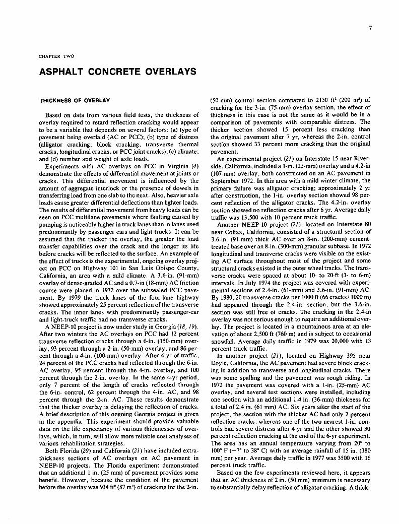
Based on data from various field tests, the thickness of overlay required to retard reflection cracking would appear to be a variable that depends on several factors: (a) type of pavement being overlaid (AC or PCC); (b) type of distress (alligator cracking, block cracking, transverse thermal cracks, longitudinal cracks, or PCC joint cracks); (c) climate; and (d) number and weight of axle loads.
Experiments with AC overlays on PCC in Virginia (4) demonstrate the effects of differential movement at joints or cracks. This differential movement is influenced by the amount of aggregate interlock or the presence of dowels in transferring load from one slab to the next. Also, heavier axle loads cause greater differential deflections than lighter loads. The results of differential movement from heavy loads can be seen on PCC multilane pavements where faulting caused by pumping is noticeably higher in truck lanes than in lanes used predominantly by passenger cars and light trucks. It can be assumed that the thicker the overlay, the greater the load transfer capabilities over the crack and the longer its life before cracks will be reflected to the surface. An example of the effect of trucks is the experimental, ongoing overlay proj-ect on PCC on Highway 101 in San Luis Obispo County, California, an area with a mild climate. A 3.6-in. (91-mm) overlay of dense-graded AC and a 0.7-in (18-mm) AC friction course were placed in 1972 over the subsealed PCC pave-ment. By 1979 the truck lanes of the four-lane highway showed approximately 25 percent reflection of the transverse cracks. The inner lanes with predominantly passenger-car and light-truck traffic had no transverse cracks.
A NEEP-lO project is now under study in Georgia (18, 19). After two winters the AC overlays on PCC had 12 percent transverse reflection cracks through a 6-in. (150-mm) over-lay, 93 percent through a 2-in. (50-mm) overlay, and 86 per-cent through a 4-in. (100-mm) overlay. After 4 yr of traffic, 24 percent of the PCC cracks had reflected through the 6-in. AC overlay, 95 percent through the 4-in, overlay, and 100 percent through the 2-in, overlay. In the same 4-yr period, only 7 percent of the length of cracks reflected through the 6-in, control, 62 percent through the 4-in. AC, and 98 percent through the 2-in. AC. These results demonstrate that the thicker overlay is delaying the reflection of cracks. A brief description of this ongoing Georgia project is given in the appendix. This experiment should provide valuable data on the life expectancy of various thicknesses of over-lays, which, in turn, will allow more reliable cost analyses of various rehabilitation strategies.
Both Florida (20) and California (21) have included extra-thickness sections of AC overlays on AC pavement in NEEP-10 projects. The Florida experiment demonstrated that an additional 1 in. (25 mm) of pavement provides some benefit. However, because the condition of the pavement before the overlay was 934 ft' (87 m2) of cracking for the 2-in.
(50-mm) control section compared to 2150 ft2 (200 m2) of cracking for the 3-in. (75-mm) overlay section, the effect of thickness in this case is not the same as it would be in a comparison of pavements with comparable distress. The thicker section showed 15 percent less cracking than the original pavement after 7 yr, whereas the 2-in, control section showed 33 percent more cracking than the original pavement.
An experimental project (21) on Interstate 15 near River-side, California, included a 1-in. (25-mm) overlay and a 4.2-in (107-mm) overlay, both constructed on an AC pavement in September 1972. In this area with a mild winter climate, the primary failure was alligator cracking; approximately 2 yr after construction, the 1-in, overlay section showed 98 per-cent reflection of the alligator cracks. The 4,2-in, overlay section showed no reflection cracks after 6 yr. Average daily traffic was 13,500 with 10 percent truck traffic.
Another NEEP-10 project (21), located on Interstate 80 near Colfax, California, consisted of a structural section of 3.6-in. (91-mm) thick AC over an 8-in. (200-mm) cement-treated base over an 8-in. (300-mm) granular subbase. In 1972 longitudinal and transverse cracks were visible on the exist-ing AC surface throughout most of the project and some structural cracks existed in the outer wheel tracks. The trans-verse cracks were spaced at about 10- to 20-ft (3- to 6-m) intervals. In July 1974 the project was covered with experi-mental sections of 2.4-in. (61-mm) and 3.6-in. (91-mm) AC. By 1980, 20 transverse cracks per 1000 ft (66 cracks! 1000 m) had appeared through the 2.4-in. section, but the 3.6-in. section was still free of cracks. The cracking in the 2.4-in overlay was not serious enough to require an additional over-lay. The project is located in a mountainous area at an ele-vation of about 2,500 ft (760 m) and is subject to occasional snowfall. Average daily traffic in 1979 was 20,000 with 13 percent truck traffic.
In another project (21), located on Highway 395 near Doyle, California, the AC pavement had severe block crack-ing in addition to transverse and longitudinal cracks. There was some spalling and the pavement was rough riding. In 1972 the pavement was covered with a 1-in. (25-mm) AC overlay, and several test sections were installed, including one section with an additional 1.4 in. (36-mm) thickness for a total of 2.4 in. (61 mm) AC. Six years after the start of the project, the section with the thicker AC had only 2 percent reflection cracks, whereas one of the two nearest 1-in, con-trols had severe distress after 4 yr and the other showed 30 percent reflection cracking at the end of the 6-yr experiment. The area has an annual temperature varying from 20° to 100° F (-7° to 38° C) with an average rainfall of 15 in. (380 mm) per year. Average daily traffic in 1977 was 3500 with 16 percent truck traffic.
Based on the few experiments reviewed here, it appears that an AC thickness of 2 in. (50 mm) minimum is necessary to substantially delay reflection of alligator cracking. A thick-

ness of 3 in. (75 mm) minimum is desirable over block crack-ing. If cement-treated base is involved, the small amount of evidence available indicates the need for 3.5-in. (90-mm) thick overlay to delay reflection cracking for at least 6 yr. The amount of traffic, climate, AC pavement deflection, differential deflection at PCC joints, and quality of the over-lay all affect the actual life of a specific project.
VISCOSITY OF ASPHALT
A significant factor in retarding reflection cracking is the viscosity of the asphalt binder at the time it is placed on the road. The temperature susceptibility of this asphalt, the climate surrounding it, the amount used, and its ability to resist hardening all affect the rate of crack progression through an AC mat.
In conjunction with the federal NEEP-lO project, in 1972 the Arizona DOT placed a series of 18 test sections on a severely cracked AC pavement on Interstate 40 near Winslow. The types of installation and their performance are described in the appendix [see Way (22, 23) for a more com-plete description]. The tests were conducted in an area at an elevation of 5,000 ft (1500 m) and with a temperature range of 0° to 1000 F (-18 to 38° C), and an annual rainfall of less than 8 in. (200 mm). Average daily traffic was 10,000. Among the conclusions reported are the following (23):
It was found that basic asphalt properties influenced the reduction of reflection cracking more than any other prop-erty. It was found that the 4.0 megapoise at 770 F viscosity (equivalent penetration about 45, absolute unaged viscosity of 3000 poises at 140° F) was critical to crack initiation. That is, the longer an asphalt can maintain a viscosity below 4.0 mega-poise, the less likely reflective cracks will occur. Actual physical crack formation and intensity is triggered by cold temperatures. As such, once the asphalt reaches the 4.0 mega-poise level, it becomes highly susceptible to cracking. This being the case, it is an important consideration that all system designs use the lowest viscosity asphalt commensurate with strength requirements, and to use it in such a way as to retard aging as much as possible.
Additional evidence concerning the effect of asphalt vis-cosity on retarding crack formation can be found in studies conducted in Canada (24-26), Oklahoma (27), and Pennsyl-vania (28). These studies reported a reduction in transverse thermal cracking using asphalts of lower viscosity in cold climates. Work done in Saskatchewan, Canada (29) indicates the possibility of air blowing asphalts to improve viscosity- temperature characteristics, which would allow the use of harder grades of asphalt in cold climates while still adhering to the viscosity requirements of cold weather.
Hignell et al. (30) reported in 1972 on work with asbestos and concluded that the low-temperature properties of all types of mixtures are primarily a function of the type of asphalt used; and that at medium to high temperatures, asbestos-fiber modification can significantly improve mix-ture stiffness properties.
Although these later studies deal mainly with cold-weather cracking of AC pavements, the horizontal stresses due to temperature are the same as those that develop in overlays on existing pavements. Along with the results obtained in Arizona (22), the results of these studies reinforce considera-
tion of asphalt viscosity in an AC overlay as a major factor in the retardation of reflection cracking.
EFFECT OF ADDITIVES
In an attempt to improve the performance of AC, additives have been incorporated to change the characteristics of the asphalt or the mixture of asphalt and aggregate. One of these additives is sulfur. Laboratory tests (31) of sulfur-asphalt mixtures have shown that the viscosity-temperature relation-ships of the asphalt are changed so that a soft (300-400 penetration) asphalt containing sulfur will have about the same mixture stiffness at below freezing and higher stiffness at 100° F (38° C) as compared to the same asphalt with-out sulfur. As shown in the Arizona experiments (23, 32), viscosity of the binder is an important factor in overlay performance. However, softer asphalts tend to be less stable at high summer temperatures and have a greater rutting potential than the harder grades. It is possible that the use of sulfur provides a mixture of sufficient stiffness for summer temperatures as well as reduced cold-weather stiffness to resist reflection cracking in the winter.
Asbestos is another additive that has been used in various experimental sections. Asbestos fibers allow the use of addi-tional asphalt in the AC overlay mixture, which should result in lower void content and retarded hardening of the asphalt. This, in turn, should result in delayed reflection cracking. In tests conducted in Arizona (22, 23), 3.2 percent asbestos and an additional 2 percent asphalt was used in one test section. At the conclusion of the project in 1978, this section was rated as the second best performer insofar as reflection cracking was concerned, and also had the smallest rut depth of any of the 18 test sections. It should be noted that because of environmental considerations, asbestos is no longer used in many areas.
In a study conducted in Canada in 1972 (30), the following conclusions were reported:
At low temperatures, the properties of all types of mixtures are primarily a function of the asphalt type used; but, at medium to high service temperature, asbestos fiber modifica-tion can significantly improve mixture properties, in com-parison to "standard conditions" and to mineral filler modification.
A major implication of this finding is that where a softer asphalt is to be used for low-temperature cracking conditions, asbestos fiber modification may be useful. Such modification may not appreciably alter low-temperature stiffness but it will increase medium to high service temperature stiffness and thereby possibly avoid violation of fatigue and permanent deformation requirements.
A third means of improving asphalt properties has been proposed by the Chem-Crete Corporation of Menlo Park, California (33). This process consists of the addition of a small amount of metal, which triggers a polymerization of the asphalt and changes the chemistry of some of the carbon groups found in asphalt. The process is currently being field tested, but no conclusive data has been reported.
Laboratory tests (34) have shown that the temperature susceptibility of the asphalt can also be improved when carbon black is used as a filler in asphalt concrete. However, field trials are necessary to determine if the laboratory evi-dence can be transformed into field performance.

CHAPTER THREE
TREATMENT OF EXISTING PAVEMENTS
SEAL COATS AS A SURFACE APPLICATION ON AC PAVEMENT
Asphalt chip seal coats have been widely used as a main-tenance treatment for AC pavement showing some distress in the form of cracking. This treatment has been successful in retarding the formation of additional cracking when the asphalt chip seal coats are applied at an early state of pave-ment deterioration. However, there is a high risk of chip loss involved in placing chip seals on heavily traveled truck routes, and little evidence in the literature that asphalt chip seal coats prevent or retard reflection cracking.
Slurry seal coats perform in a manner similar to asphalt chip seals in that their primary function is to retard surface abrasion and prevent surface water from entering the pave-ment. Cracks beneath a slurry seal will soon come to the surface but generally will be narrower. However, the effects of traffic and climate will eventually open the cracks to their original width.
Open-graded seal coats (AC friction courses) placed on the surface of a pavement appear to retard cracks from reflect-ing; or it may be that the rough texture tends to hide or minimize the crack for a period of time. As the asphalt hardens, cracks become visible and spalling of the open-graded mix occurs at the crack.
A primary surface seal coat application for retarding re-flection cracking is the asphalt-rubber surface treatment known as the SAM (stress absorbing membrane). Developed in Arizona by McDonald (35, 36), and first reported in 1966, this treatment has been the subject of much research and many field trials.
Two types of asphalt rubber are being marketed for use in the SAM process. OVER-FLEX, the product of the Sahuaro Petroleum and Asphalt Company of Phoenix, Arizona, con-sists of vulcanized rubber (approximately No. 10 to No. 30 sieve-2.00 mm to 600 pm) in combination with asphalt (37). A solvent extender oil is added to aid the blending process and to improve spraying characteristics. The blend is made in the field, and the rubber and blending oil are added to asphalt at approximately 400° F (204° C) and sprayed on the roadbed using distributor trucks modified for this specific application.
The asphalt-rubber blend consists of 75 to 80 percent pav-ing asphalt blended with 20 to 25 percent ground vulcanized rubber and ito 5 percent extender oil. The blend is generally spread on the pavement at a rate of 0.45 to 0.70 gal/yd2 (2.0-3.2 L/m2 ) depending on aggregate size, roadway sur-face, etc.
For cover material, clean crushed rock or gravel conform-ing to either No. 7 or No. 8 gradation limits of AASHTO M 78-64 is generally preheated, and often precoated, and is applied in sufficient quantities to form an aggregate structure
to transmit loads to the underlying pavement (37). The thick-ness of the membrane system will range from 0.35 to 0.75 in. (9-19 mm).
ARM-R-SHIELD, the asphalt-rubber material marketed by the Arizona Refining Company of Phoenix, Arizona, is a blend of 40 percent powdered devulcanized rubber and 60 percent powdered vulcanized rubber high in natural rubber (30 percent minimum) (38). This material may be applied at the same general rate (0.45 to 0.70 gal/yd2 ) as described above. Aggregate can be spread at a rate between 30 and 50 lb/yd2 (16 and 27 kg/m2 ) depending upon the applied film thickness or the amount determined by the method outlined by Vallerga and Bogley (39). It is recommended that aggregate be preheated not to exceed 300° F (149° C) and precoated with 0.25 to 0.75 percent asphalt (40).
A substantial amount of field and laboratory research has been conducted concerning the use, performance, and construction requirements of asphalt-rubber material (22, 23, 36, 38, and 41-47). The Arizona Minnetonka-East NEEP-lO project (22, 23) contained one test section with an asphalt-rubber precoated chip seal (SAM). In 1975 this section was ranked near the bottom in reflection cracking performance, but was ranked among the top five in 1978 after an additional seal coat (23).
The Arizona reports (22, 23) claim excellent success in the retardation of the reflection of fatigue cracking of AC pave-ments. Thermal cracks have reflected through the asphalt-rubber seal coat but are narrow and tend to heal during warm weather. The Arizona experience covers a variety of climates, ranging from desert to mountainous and from low rainfall to snow and icy conditions. An asphalt-rubber seal coat was also applied successfully at the Phoenix Sky Harbor Airport in 1971 (44).
Gonsalves (46) reported that the SAM process, when prop-erly constructed, results in satisfactory skid resistance. Some roughness problems were reported, and some projects were covered with an asphalt finish course after approxi-mately 4 yr., which altered the construction from a SAM to a SAMI (stress absorbing membrane interlayer) with improved ride qualities.
The SAM process appears to have potential for extending the life of an asphalt pavement. Projects are being placed in many states, cities, and counties, and reliable information on life expectancy of the SAM layers should be available for different climatic conditions within a few years. Costs of placing the asphalt-rubber SAM varies widely throughout the United States depending on the distance to the nearest sources of asphalt-rubber material. In 1979 the average cost for eight projects was $1.121/yd2 ($1.34/rn2) with a high of $ 1.452 ($1.74) and a low of $0.830 ($0.99) (23).
In 1974 and 1975 the Naval Civil Engineering Laboratory at Port Hueneme, California, placed a series of the asphalt-

10
rubber seal coat (SAM) test patches on AC runways and taxiways at the National Parachute Test Range at El Centro, California; the Naval Air Station at Miramar, California; and the Naval Air Station at Fallon, Nevada (48). The conclu-sions reached from these limited tests generally correlate well with those from the Arizona tests. It was found that after 2 yr, the asphalt-rubber seal was still functioning over fatigue cracking where the pavement had not yet begun to fail under load. This study found that shrinkage cracks reflect before fatigue cracks, and that wide shrinkage cracks (greater than 0.5 in.-13 mm) reflect almost completely within 1 yr after sealing. It was also reported that the SAM-type seal coat provided excellent skid resistance.
States with chip seal, asphalt-rubber projects include Cali-fornia, Colorado, Connecticut, Georgia, Mississippi, Rhode Island, Texas, Vermont, and Washington. The process has been used for maintenance in Flagstaff, Phoenix, and Prescott, Arizona; Hays, Kansas; Hingham, Montrose, and Springfield, Massachusetts; and other cities.
REJUVENATING AGENTS
Two direct-application products have been used for re-juvenating existing AC: Reclamite, from the Golden Bear Oil Company; and Petroset AT, from Phillips Petroleum (Petroset AT is no longer marketed). Reclamite is a petro-leum resin-oil base emulsified with water. It is effective in penetrating pavement and tends to soften the surface by adding oily fractions to the asphalt, with a resultant lowering of viscosity. With the low viscosity, cracks tend to surface heal under traffic and temperature. In practice, the sealing effect tightens the surface, makes it more water-resistant, and retards or prevents surface raveling; it does not, however, eliminate cracks.
Petroset AT is also a penetrating emulsion to which rubber has been added; its purpose is to penetrate the mat through interconnecting voids and rubberize the AC. The amount of penetration depends on the density of the AC layer. Its effect on the road surface is similar to that of Reclamite.
A problem can occur with the use of either material on the final surface if the AC mix already contains sufficient asphalt and has proper compaction. Under these conditions, adding Reclamite or Petroset AT tends to over-asphalt the surface and can cause flushing, with a resulting low skid resistance. This is not true of old, dry pavements, where these additives have-been used successfully to liven up the surface of the existing AC.
Several experiments have been conducted involving the application of Reclamite and Petroset AT under an AC over-lay and on a new overlay to keep it more flexible. In Florida (20) no beneficial effect was found from either of the agents. Colorado (49) used both products on sections in its experi-mental 1-70 NEEP-10 project; however, because of surface flushing, it was necessary to cover both with additional AC, which, coupled with a heavier than normal leveling course, made results difficult to evaluate. The North Dakota experi-ment (50) showed that applying Petroset to the surface of the overlay was beneficial with respect to reflection cracking; however, there was increased flushing and probably lower skid resistance.
HEATER-SCARIFIER PROCESS
Much rehabilitation work has been performed by means of the heater-scarifier process, which consists of heating and scarifying 0.75 to 1 in. (19 to 25 mm) of the existing pave-ment, adding a rejuvenating agent, and recompacting the material. In most cases, the remixed layer is covered by an AC overlay. Arizona (32, 51), Colorado, and Nevada have all done a significant amount of work in this area. The purpose of using the heater-scarifier process in the upper portion of the pavement is to eliminate the wide cracks caused by spall-ing and to provide a narrower crack beneath the overlay. Many of the cracks formed in AC are Y-shaped, with the crack at the surface of the pavement being spalled to a greater width than the crack in the middle and lower portion of the AC pavement. However, some cracks are the same width through the entire pavement.
An advantage of the heater-scarifier process is that when covered with an additional layer, the remixed layer serves as an increased thickness of overlay, which will slow the reflec-tion cracking process of AC pavements.
In the Arizona Minnetonka-East NEEP-10 project, the heater scarification plus Reclamite test panel was ranked as the third best performer (32; appendix). From 1975 to 1979, 360 miles (580 km) of highways in Arizona were overlaid using the heater-scarifier process.
No data are available on the life expectancy of the heater-scarifier process covered with various thicknesses of AC.
CRACK FILLING—AC AND PCC
There is little reported experimentation on the effect of crack filling on reflection cracking. For almost every overlay process, whether it be the laying of an AC layer or the use of asphalt-rubber layers, fabric, or open-graded mixes, it is recommended that cracks greater than ¼ or 41 in. (6 or 9 mm) wide be filled before overlaying. Experimental evi-dence of a beneficial effect was reported by Monismith and Coetzee (52) using two-dimensional finite-element analysis with and without crack filler.
Field tests provide conflicting information on the perform-ance of filled cracks. Wyoming constructed an experimental AC overlay project in 1971 (53). Part of the experiment was to determine the effectiveness of a crack sealant consisting of 90 percent CRS-2 emulsion and 10 percent latex rubber. It was concluded that the crack sealer placed directly under an AC overlay did not significantly reduce reflection cracking. When the crack sealer was placed under a cushion course, the least amount of cracks occurred in the overlay.
In Texas (54) a sulfur compound was used as a crack filler on the auxiliary PCC runway at Kelly AFB. It was claimed that the sulfur compound acted as a load transfer at the cracking and minimized reflection cracking.
In January 1977 the Nova Scotia Department of Highways (55) reported on the results of field experiments in pres-sure filling cracks wider than '/8 in. (3 mm) with Colas Rubberized Crack Filler, a Flintkote product. The main pur-pose of the procedure, which was instituted in 1974, was to reduce reflection cracking on pavements covered with a chip seal coat. A noticeable reduction in reflection cracking was reported.

11
The purpose of filling cracks under an overlay is to restrict surface water from entering the supporting base and sub-grade. A subgrade and base with reduced moisture provide greater load support, less surface deflection under load, and consequently less potential for reflection cracking.
STABILIZING PCC SLABS BY SUBSEALING
The need for stabilizing PCC slabs by subsealing before overlaying has been discussed previously (4). This process is necessary to minimize the differential slab movement at a crack or joint, because even slight differential movement can cause reflection cracks in an ACC overlay (4). Although the process of subsealing provides a more stable layer for an overlay, alternative procedures are sometimes used (i.e., slab breaking or increasing the thickness of the overlay to dampen differential vertical movement) because subsealing is slow, laborious, and costly.
In 1970, on a slab-jacking project in Louisiana, field trials of various slurry materials as well as laboratory tests were conducted (56). Trials were made using A-4 soil mixed with 4 bags! yd3 (376 lb / yd3 or 223 kg / m3) of portland cement and water. The addition of a wetting agent to the water appeared to aid travel of the slurry without loss of strength. The addi-tion of emulsified asphalt in quantities up to 15 percent of the mixing water did not significantly increase the flow of slurry and resulted in some loss of strength.
In 1981 Del Val (57) recommended the use of one part portland cement and three parts pozzolanic material (fly ash) as a subsealing slurry. It was claimed that the fly ash particles and their predominantly spherical shape enable the slurry to be more easily pumped to fill voids than mixtures of portland cement and other mineral materials. Field trials are currently under way using this material. If the material proves success-
ful in filling voids under slab joints and cracks, it could aid in minimizing the amount and severity of reflection cracks in both AC and PCC overlays.
STABILIZING PCC SLABS BY BREAKING
There have been several experiments in which old con-crete pavements were broken into smaller segments before overlaying. The procedure of using a 50-ton (45-Mg) pneu-matic roller to break the pavement and put it in contact with the underlying base was reported by Kipp and Preus in Minnesota in 1950(58), by Velz (59) in 1961, and by Korthage (60) in 1970. A hydraulic or pneumatic hammer can also be used. Kanarowski (10) reported that of five states using heavy rollers to break and seat PCC pavement, all had appar-ent success in retarding reflection cracks with this method.
Lyon (61) reported in 1970 on a 10-yr study in Louisiana involving the breaking and seating of slabs with a pneumatic roller. He compared the results of the study with pavement broken by a pneumatic hammer and a hammer and roller. He concluded that the hammer and roller combination was the most effective (Figure 2). It should be noted that most of the early work using the rollers was on older PCC pavements and usually on wet or weak subgrades. According to Lyon, it is to be expected that the roller-breaking treatment would be less effective over strong subgrades. He recommended that the process be used only on subgrades with moisture content at or above optimum; this was confirmed in California when a 50-ton (45-Mg) roller failed to crack an existing 8-in. (200-mm) concrete pavement constructed over a 4-in. (100-mm) cement-treated base and a stable subgrade. Lyon also stated that one of the reasons for the reduction in reflection cracking was the reduction in Benkelman beam deflections (Figure 2).
YR. = 2 YR. IYR.
ROLLER ONLY 2 COVERAGES
90 90
HAMMER ONLY
ea
- RL- — -- TC --
L--- --
NANER ONLY
ROLLER ONLY 2 COVERAGEO
Z
- 4MMORO
HAMMCRO LLER - TYPE OP. TREATMENT
FIGURE 2 Changes in deflections and reflection cracking for 1, 2, and 10 yr of exposure to traffic compared with original conditions for various treatments (Louisiana) (61).

12
In 1980 Noonan and McCullagh (62) reported that the pro-cedure of breaking rigid pavement plus sawing joints in the AC overlay on old rigid pavement joints was generally suc-cessful in reducing reflection cracking.
PAVEMENT RECYCLING
The pavement-recycling process involves the milling of a layer or layers of a pavement, adding asphalt, rejuvenating agent, or aggregate as required, and then remixing, relaying, and recompacting. When the entire pavement is recycled, the possibility of reflection cracking from the recycled materials is eliminated (63). If an additional surface layer is placed on the recycled pavement, the resultant heavier structural sec-tion should outperform the original pavement.
One advantage of this method is that the vertical grade line is raised a minimum amount. In the case of multilane high-ways where the inner lanes and shoulder areas are in satisfac-tory condition and only the outer lanes require rehabilitation,
considerable savings in overlay materials can be realized. A minimum thickness of overlay can be placed over the entire pavement. In cities or urban counties where it is desirable to maintain curb lines and drainage, the recycling process is advantageous because it reduces the reflection cracking potential without using a thick overlay.
Projects involving the recycling of AC and PCC pavements ments are described in NCHRP Synthesis 54 (63) and will not be reviewed here. It is sufficient to conclude that the recycl-ing process eliminates existing cracks and, therefore, their reflection through a covering layer. Evidence of the benefit was provided in a 5-yr test in Ontario, Canada (64), which compared using a 4-in. (100-mm) overlay on AC pavement to using granular interlayers or pulverizing the old surface as a base with and without the addition of asphalt. The most viable alternative, from the standpoint of minimum re-flection cracking and economic analysis, was found to be pulverization of the existing surface for use as a base. The 4-yr performance of the enriched pulverized AC was equally as effective for reducing reflection cracking but less economical.
CHAPTER FOUR
STRESS-RELIEVING INTERLAYERS
During the 1970's, stress-relieving interlayers were widely used in experiments designed to reduce or prevent reflection cracking. The experiments involved overlays on both AC and PCC. For AC, attempts were made to prevent or slow the reflection of alligator fatigue cracking or transverse and longitudinal cracks. For PCC, the aim was to prevent or slow the reflection of transverse joint cracks as well as structural cracks developed under traffic.
The principal objective of the interlayer experimentation was to minimize the thickness of overlay needed to rehabili-tate a road surface by retarding or eliminating reflection cracking for the design life of the project. This is economi-cally important for all roads, but has particular significance for multilane highways where although inner lanes may have adequate structutal and ride ratings, outer lanes with concen-trated heavy wheel load traffic may require rehabilitation. Overlays must cover all lanes and, in many cases, additional materials are required for the shoulders. Therefore the thin-nest overlay that will provide the required design life for the truck lanes will generally be the most economical design.
Although laboratory experimentation and theoretical anal-ysis have determined that interlayers can reduce the high stresses developed at a crack (see Chapter 6), as yet a proven design method to utilize stress-relieving interlayers to the fullest advantage has not been developed.
In various projects, seven interlayer methods have been
tested to determine their effectiveness in retarding reflection cracking:
Asphalt-rubber layer under an AC overlay. Prefabricated fabric membrane strip. Fabric layer under AC. Low-viscosity asphalt in an AC layer placed under a
layer using a normal paving-grade asphalt. Open-graded AC base layer. Open-graded AC layer 1.5 in. (38 mm) or less in thick-
ness. Gravel or crushed rock layer.
ASPHALT-RUBBER INTERLAYERS
The Arizona Department of Transportation has conducted extensive field research on the use of asphalt rubber both as a seal coat (the construction process referred to as SAM) and as an interlayer (the construction process referred to as SAM!) under an AC wearing course. The chemical and physical properties, testing methods, construction tech-niques, and performance of the asphalt-rubber layer over both AC and PCC have been described in several reports (22, 23, 26, 36, 38, 41-44). Most test applications have been on AC pavements.
The two types of asphalt rubber described in the discus-

13
sion on seal coats in Chapter 3 have been used to provide interlayers under an AC surface course. Arizona has been a leader in the study and use of SAMI construction for reduc-ing reflection cracking. The purpose of the SAMI process and the importance of proper construction practice are de-scribed as follows (47):
The procedure in placing the SAMI is similar to that used in placing the SAM. However, in the design of SAMI system, it is important to keep in mind that the SAMI must provide for strain attenuation in the horizontal direction and must be capable of transferring vertical loads so that excessive deflec-tions do not occur in the overlay. Embedding aggregate into the hot cast-in-place asphalt-rubber membrane also has a primary function of protecting the membrane from damage by construction traffic. In general, the aggregate may be any suitable single size material ranging from chips to pea gravel or coarse sand.
The quantity of asphalt-rubber sprayed is generally within the range of 0.6-0.8 gsy [gall yd2 ]. The rate of spread of the aggregate is kept to a minimum (15-25 psy) [161yd2 ] with just enough aggregate to give a working surface. This is to ensure that the resulting SAMI will exhibit primarily the desired properties of the asphalt-rubber material with least inter-ference from the aggregate particles. The SAMI so con-structed will have a thickness of 0.35 to 0.50 inches (9 to 13 mm).
The NEEP-lO experimental project in Arizona (22, 23; appendix) consisted of 18 sections; 2 sections were con-structed in 1972 using a SAMI covered with a 0.5-in. (13-mm) AC finish course. The SAMI construction was rated as one of five treatments that significantly reduced reflection crack-ing over old AC pavements (22) and also was reported the top-rated treatment (23).
A second type of asphalt rubber made from a mixture of powdered reclaimed rubber and ground scrap high in natural rubber content has been used in SAMI construction projects reported as showing promising performance (38).
In March 1981 Mascunara (65) reported on an Illinois reflection-crack study of AC overlays on both AC aI)d PCC pavements. The study included a test of an asphalt-rubber interlayer. Based on the test results, asphalt rubber was recommended for use over flexible bases and for longitudinal joints, such as center-line or other lane joints, and widening joints over a rigid base.
Gonsalves (46) reported the successful use of SAMI construction over both PCC and AC in 29 Arizona pro-jects. Other states reported to be experimenting with SAMI construction are California, Connecticut, Montana, New Hampshire, New Mexico, Oklahoma, Texas, Utah, Vermont, and Washington (47). Brown (66) reported that the FHWA Demonstration Projects Division had participated in the construction and evaluation of 23 asphalt-rubber inter-layer projects in 20 states.
PREFABRICATED FABRIC MEMBRANE STRIPS
The 1-85 Gwinnette County reflection- crack study in Georgia included testing the effectiveness of placing 18-in. (450-mm) wide strips of Bituthene, a prefabricated mem-brane, over the transverse and longitudinal center-line and shoulder joints of PCC pavement. The strips were covered
with 2 in. (50 mm), 4 in. (100 mm), and 6 in. (150 mm) AC resurfacing (18; appendix). (Previously Bituthene had been used as a membrane for bridge decks under an AC overlay.) Traffic was permitted to travel on the strips for 1 day before a leveling course and the required thickness of AC were placed.
The performance and use of the prefabricated membrane in Georgia was described as follows (18):
The use of heavy duty waterproofing strips over concrete pavement joints and cracks prior to an asphalt concrete over-lay has prevented cracks from occurring in a 2-in. (51-mm) thick asphalt concrete overlay after 15 months of service. The corresponding control section without the waterproofing strips has 88 percent of the concrete joints reflected through the overlay.
The excellent results obtained to-date with the water-proofing membrane has resulted in the use of this material on other major Interstate overlay projects on 1-24, 1-85 and 1-285 for a total of approximately 760,000 lineal feet (232 000 m) of waterproofing material. The width of strips used on the experimental project was 18 in. (457 mm), but this was reduced to 12 in. (305 mm) for the contract projects. The in-place cost of the waterproofing strips on the three projects average $0.50 per lineal foot ($1.64/rn). The decision to recommend the waterproofing strips was based upon its early excellent performance and lower cost as compared to the engineering fabrics.
Data on the performance of Bituthene in Georgia after 4 yr indicate that the material is still performing well, particularly under the 4- and 6-in. (100- and 150-mm) overlays (19; appendix). When concluded, the test project in Georgia should provide excellent data on the performance of AC overlays of variable thickness used both alone and over en-gineering fabrics and prefabricated membranes as well as data on the Arkansas open-graded base design. In addition, the project also includes edge drained sections and a series of PCC overlays.
FABRIC INTERLAYERS
Starting in the late 1960's and continuing through the 1970's, there has been an increasing use of synthetic fabrics under AC overlays (Figure 3). The fabrics are manufactured from polypropylene, glass, nylon, polyester, or combina-tions of these and other fibers (67). The principal fabrics cur-rently in use in the United States for pavement rehabilitation are polypropylene and polyester. These fabrics are manu-factured by several processes, including needle-punched, spunbonded, woven, and various combinations of these pro-cesses (67).
Fabric layers are used to retard or prevent reflection cracking and to waterproof the pavement structure to pre-vent surface water from entering an AC overlay. Field experimentation to verify the effectiveness of fabric layers was given impetus in May 1970 when the FHWA initiated the National Experimental and Evaluation Program Project No. 10 (NEEP-lO). Most of the projects constructed under NEEP-lO included test sections utilizing fabrics, with as many as three different synthetic materials being tested in some projects.

14
The fabrics tested in the NEEP-lO projects are listed below (67):
FABRIC NAME FABRIC TYPE MANUFACTURER
Cerex Spunbonded nylon Monsanto Petromat Nonwoven polypropylene Phillips Petroleum Stnctofors Open-weave polyester American Enka Fibcr glass Matting I'PG Industries Glass fabric Woven Burlington Mirafi 140 Spunbonded polypropylene/nylon Celanesc
The number of tests conducted for each of the above fabrics as part of the NEEP-lO project varied.
Proper preparation of the surface to be covered is critical to the performance of fabric interlayers. All potholes and large cracks in AC should be filled by acceptable practices. If necessary, a leveling course should be applied. For the fabric to be an effective water retardant, an asphalt tack coat must be used to fill the voids in the fabric. If wide, unfilled cracks are allowed under the fabric, there will not be suf-ficient asphalt to penetrate the fabric and the fabric may not
TABLE I FABRIC INTERLAYERS TESTED IN VARIOUS STATES
Pvmt. State Type Fabric Tested Reference
Arizona AC Petromat, fiber-glass matting 23, 32
California AC Cerex, Petromat 21 PCC Petromat 21
Colorado AC Cerex, Petromat 49
Florida AC Petromat, Structofors 20
Georgia PCC Petromat, Mirafi 18
Iowa PCC Cerex, Petromat, Structofors 68
Kansas AC Petromat 17
Louisiana PCC Petromat 69
Missouri AC Petromat 17
Nevada AC Petromat 17
New Mexico PCC Petromat, Mirafi 17
North Carolina PCC Fiber glass, Structofors, Mirafi, Petromat 16
North Dakota AC Structofors, Petromat 50
Oklahoma AC Mirafi, Petromat 17
Pennsylvania AC Petromat 17
South Dakota AC Petromat 70
Texas AC Petromat, Mirafi 71 - 77
Virginia PCC Petromat, Cerex 4, 78, 79
Wyoming AC Petromat 17
FIGURE 3 Fabric interlayer is tacked to old PCC before overlaying.
prevent water from entering the crack. In the case of PCC, not only should cracks be filled but, to obtain the best results, slabs must also be stabilized so that differential vertical movement at the slabs is minimized 4).
The tests of fabric interlayers conducted by various states as part of the NEEP-lO project are listed in Table I. Some of the tests, representative of multiple designs and differ-ences in climates and locations, are presented in more detail in the appendix.
Fabric Interlayers Over PCC Pavement
Bituminous overlays placed on PCC pavement are subject to both vertical and horizontal stresses. The horizontal stresses are caused by thermal movement of slabs at cracks or joints. The amount of differential vertical movement de-pends on the load-transfer ability at the crack. This, in turn, depends on slab temperature, the support beneath the slab, efficiency of dowels, traffic, curling of the slabs, and the moisture present in the underlying support layers. Unfor-tunately, few differential slab measurements were performed in tests under the NEEP-lO project, and thus it is difficult to discern whether reflection cracks were caused by horizontal or vertical movements. In most cases, the cause of reflection cracking is probably a combination of both horizontal and vertical movements.
The effect of the use of fabric on crack reflection where there is differential vertical movement at cracks was reported in Virginia 4, 79). The results of a project on Route 460 in Virginia after 8 months of service are presented in Table 2. The pavement on Route 460 was PCC with 30-ft (9-rn) joint spacing. In 1972 3-ft (0.9-m) wide strips of Petromat were placed over 99 joints and covered with 1.25 in. (32 mm) AC.

TABLE 2 CRACKING AND DIFFERENTIAL DEFLECTION AFTER 8 MONTHS OF SERVICE (ROUTE 460, VIRGINIA)
Differential Deflection
d (in.)
Joints
Fabric
Cracked
Control
Joints
Fabric.
Uncracked
Control
Joints
Fabric
Cracked (%)
Control
0 0 4 20 5 0 44
0.002 7 20 17 17 29 54
0.004 23 35 3 12 88 74
0.005 14 11 2 0 88 100
0.008 12 20 0 0 100 100
15
in. = 25.4 ntn
In a second project on 1-95 near the Pentagon in Virginia, both Petromat and Cerex fabric strips were placed over joints of PCC. The results were similar to those of the Route 460 project. The following conclusions were based on the results of the two projects in Virginia (4):
Neither sand as a bond breaker nor high strength fabrics as stress relieving layers are effective in reducing reflec-tion cracking where vertical joint movement (differential deflection) is a significant factor.
When differential deflections are greater than about 0.002 in. (0.05 mm) reflection cracks form early. Such crack-ing is delayed for lower differential deflection but may occur as the magnitude and frequency of wheel loadings increase.
Both an asphalt impregnated polypropylene fabric and an unwoven, spun-bonded nylon fabric, when placed to span joints in portland cement concrete base and covered with an asphaltic concrete overlay, are able to sustain the formation of reflection cracking in the overlaying layer without under-going damage.
An asphalt impregnated polypropylene fabric spanning the joints in portland cement concrete pavements, and placed between the pavement and an asphaltic overlay, may be effec-tive in reducing the infiltration of surface water to pavement sub-layers. There is some evidence that pavement pumping may be reduced by this method.
Both an asphalt impregnated polypropylene fabric and an unwoven, spun-bonded nylon fabric can delay the forma-tion of reflection cracking. There is strong evidence, however, that such cracking is fatigue in nature and will eventually develop under the application of repetitive wheel loadings.
Other states reporting experiments with fabric placed on PCC are Iowa, Louisiana, Georgia, and North Carolina. Dur-ing a 5-yr period, Iowa tested three fabrics under a 3-in. (75-mm) AC overlay on an existing 20-ft (6-m) PCC widened to 24 ft (7.3 m) (68). It was reported that in compar-ison to the control the use of fabrics reduced reflection cracking, and that reflection cracking over the pavement-widening crack was nearly eliminated. It was also noted there was a disparity between reflection cracking on the rural sections of the road and that on the urban sections. For example, transverse cracking over Petromat in the rural sec-tion was 16 percent after 5 yr compared to 50 percent in the control. In the urban section there was about 40 percent reflection cracking compared to 60 percent in the control.
In tests in Louisiana the use of two fabrics on PCC failed to eliminate or reduce cracking in comparison to the control sections (69).
In Georgia a test involving the use of Mirafi and Petromat over PCC (18, 19; appendix) showed the benefit of thicker overlays over fabric in comparison to the control sections. Overlays in thicknesses of 2, 4, and 6 in. (50, 100, and 150 mm) were applied to both control and fabric test sections. The cracking data are given in Table 3. There appears to be a definite retardation of total cracking with the use of fabrics.
The test in North Carolina (16) utilized a uniform 2-in. (50-mm) overlay thickness at six locations selected statisti-cally (see the appendix for a more detailed description of the
TABLE 3 CRACKING IN OVERLAY (SOUTHBOUND LANE, 1-85, GWINNE11 COUNTY, GEORGIA) (19)
Asphalt Concrete Overlay
5.1cm 10.2 cm
15.2cm
Reflection Severity of Reflection Severity of Reflection Severity of Treatment Cracking Crackingt) Cracking Cracking Cracking Cracking Before Overlay' (%) (%) (%) (%) (%) (%)
Bituthene 87 44 57 17 0 0 Mirafi 100 80 60 24 4 1 Petromat 98 . 71 57 22 18 4 Edge drain 100 93 98 78 66 29 Control 100 98 95 62 24 7
Note I cm = 0.39 In. 'Arkansas ease (16 percent and 6 percent) was also used. bLength of transverse cracking reflected tluouglr overlay as percentage of total length of transverse jointL

16
project). The test showed little benefit from four types of fabrics, but did demonstrate the importance of location. It was concluded: "Joint cracking seems to vary much more with location along the highway than with different overlay treatments." The results of this experiment, as well as those of other experiments, indicate the need for multiple tests or identical conditions when comparing the performance of new materials with existing or known performances. A single test can be misleading. The North Carolina test also demon-strated the need for prior physical tests to determine if the test sections are indeed comparable.
The test in North Dakota (50) consisted of seven test sec-tions covering 13.79 miles (22.2 km) on 1-94 (see the appendix for a more detailed description of the project). Five major test sections varied from 2.4 to 2.8 miles (3.9-4.5 km) in length. A 2-in (50-mm) overlay was placed on the entire pavement width of the existing road consisting of a 5-in. (125-mm) overlay reinforced with welded wire fabric over a thickened-edge PCC pavement. Both Petromat and Structofors were tested, the former in a 2.76-mile (4.4-km) section and the latter in a 0. 18-mile (0.3-km) section. The reflection cracks in this experiment were primarily trans-verse cracks reflected through from the PCC pavement. The graph in the appendix shows that the control section per-formed as well as the other test sections and better than most. Variations in performance were averaged out in the long test sections.
The use of fabric as an interlayer over PCC pavement would not appear to be advantageous under thin [2-in. (60-mm) or less] overlays. The Georgia experiment should provide additional data on the effect of fabric interlayers under thicker bituminous overlays.
Fabric interlayers Over AC Pavement
The use of fabric interlayers over AC pavement has been tested in many states, counties, and cities. The results of many of the tests have not been reported, and the results of the reported tests are varied. The most favorable results have been reported from California (21), Colorado (49), Florida (20), and Texas (77). Tests with unfavorable results were reported from Arizona (23), California (80), Colorado (81, 82), Maine (83), Vermont (84), and Wyoming (17).
The test in Colorado (49; appendix) was conducted on 1-70 in the west central part of the state. Ten pairs of 1000-ft (300-m) test sections were installed; Petromat was used in two pairs of the test sections. The test was made on pave-ments with both transverse and longitudinal cracking as well as alligator cracks. After 5 yr of exposure to traffic, the Petromat sections showed the best results with less than 5 percent reflection cracks compared to 70 percent in the controls.
Both Petromat and Structofors were tested in Florida (20; appendix). The Petromat section performed best, with 31 percent less cracking than in the original pavement. The control and Structofors sections showed increases in crack-ing of 33 percent and 76 percent, respectively. However, the control and Petromat sections were among the least cracked sections at the start of the test, which may have influenced the performance of these sections. The increased cracking in
other test sections raises the question of the structural ade-quacy of the roadbed even with the addition of the overlay. The second best performing section was the extra-thickness section [3 in. (75 mm) as compared to 2 in. (50 mm) used on other sections], but even this section developed only 15 per- cent less cracking than the original pavement. However, the extra thickness was placed on the most cracked section of the original pavement.
The Arizona Minnetonka-East test included one section with fiber-glass matting and one section with Petromat. At the end of the 1975 test period, they were ranked 3rd and 6th in performance among the 18 test sections (see the appendix).
In California Petromat has been used in several test projects (21). The most successful tests involved placing Petromat over alligator cracking. On two AC projects, one on I-iS near Riverside (13,500 ADT with 10 percent truck traffic) and one on Route 78 near Vista (40,000 ADT with 10. percent truck traffic), the life of the 1-in. (25-mm) overlays with Petromat was estimated to be 3 to 4 yr greater than without Petromat. On the I-IS project, test panels using over- lays of 0.35 ft (4.2 in.-107 mm) as a control and similar overlays on Petromat showed no reflection cracking through-out the 5-yr life of the project.
On a project on Route 395 in northern California (3500 ADT, 16 percent truck traffic) with thermal cracking, a sec- tion with a 2 ½-in. (64-mm) overlay performed better than a 1-in. (25-mm) overlay on Petromat. However, after 6 yr the fabric section outperformed the controls and was still func- tioning after three of five control sections were resurfaced with a seal coat. An interesting sidelight from this experiment was reported on the section utilizing Cerex (no longer marketed). When a windrow of hot AC was placed on the Cerex, it wrinkled so much that the experiment was aban-doned. However, the 0.30 gal/yd2 (1.4 L/m2 ) tack coat was left on the pavement and the section performed slightly better than the Petromat section: 13 percent reflection crack-ing compared to 18 percent for the Petromat and 2 percent for the extra-thickness section.
Wyoming reported that Petromat placed on a thermal-cracked test section failed to produce any benefit, with cracking in the control and Petromat sections about equal (17).
Texas (77) has tested Fibertex and Petromat, reporting construction problems with wrinkling of the Fibertex; data on performance have not yet been reported. Petromat, the primary fabric tested, has been used as an underseal and covered with a chip seal coat on bituminous roads. This process appears to be most effective on low-volume roads or as a maintenance operation to prevent potholes on severely alligator-cracked roadway. Petromat has also been tested under AC and under open-graded friction courses (71, 72). On 1-40 near the Potter County line, use of fabric underseal caused a reduction in number and size of cracks compared to the control section (71).
On a project on 1-20 west of Pecos, Texas (72), the sections listed below were constructed and compared. Based strictly on performance, the control section was judged the best after 2 yr. Costs of the four types of sections were:
1. Petromat underseal, one-course surface treatment, and 0.75-in. (19-mm) open-graded friction course: $1.51/yd2 ($1.81/rn2).

17
One-course surface treatment underseal and 0.75-in. (19-mm) open-graded friction course: $0.70/yd2 ($0.84/rn2 ).
Two-in. (50-mm) Type C HMAC, fabric underseal, one-course surface treatment, and 1.25 in. (32 mm) Type D HMAC: $3.65/yd2 ($4.37/rn2 ).
One-course surface treatment, 2 in. (50 mm) Type C HMAC, and 1.25 in. (32 mm) Type D HMAC: $2.84 / yd 2 ($3.40! m2).
Use of Fabric Interlayers to Retard Water Penetration
Further evaluation is necessary before the use of fabrics can be included in design concepts. The benefits of asphalt-saturated fabrics in retarding penetration of water have been recognized by some agencies, but the benefits have not been quantified. For overlays on PCC, the elimination or reduc-tion of surface water available under the slab should reduce pumping and faulting. For AC pavement, a reduction of the surface water available to base and subgrade materials should result in lower deflections in the spring and in thinner structural overlay requirements, especially in areas where frozen base and subgrade do not cause problems. It should be noted that placing a water barrier between the overlay and original cracked pavement can cause problems where sub-surface water is available from outside the pavement area. The use of a fabric or any other layer to retard penetration of water will not substitute for a good drainage design.
LOW-VISCOSITY AC INTERLAYERS OVER AC PAVEMENT
As early as 1962, Nevada was using stress-relief courses over distressed AC pavements (J. C. Hodge, internal memorandum, Nevada Department of Highways, Oct. 1975). MC-3000 or SC-3000 asphalts were used as binders for a leveling course of ito 1.5 in. (25 to 38 mm) in thickness. The SC-3000 required a longer period of time for volatiles to leave the mixture before it was covered with the surface course; otherwise, volatiles tended to soften the surface course, particularly when the leveling course was mixed in a dryer-drum plant at low temperatures. AR-bOO asphalt has been used successfully in the leveling course, but it is not always available.
Nevada has used AC made with 85-100 penetration or AR-4000 asphalt as a surface course over the stress-relief course. These harder asphalts in the surface course provide a stiffer mixture with greater resistance to chain or studded-tire wear as well as to rutting under heavy truck traffic.
On several projects in Nevada, performance of overlays with and without the soft interlayer was studied; it was con-cluded that the interlayer provides an extended overlay life (J. C. Hodge, internal memorandum, Nevada Department of Highways, Oct. 1975). Approximately 250 miles (400 km) of roadway have been constructed using the interlayer system. An 8- to 9-yr life expectancy with some minor reflection cracking (mostly transverse) is anticipated. The performance of the interlayer, which utilizes a relatively low-viscosity bitumen, parallels that of the 200-300 penetration AC overlay
section in the Arizona Minnetonka NEEP-lO project, which was judged one of the best in performance. Thus the experi-ence in Nevada confirms the conclusion reported by Arizona that bitumen viscosity is a significant factor in retarding re-flection cracking.
In 1971 the Wyoming Highway Department constructed an experimental project [on 1-80 between Cheyenne and Laramie at an elevation of 8600 ft (2600 in)] to evaluate the benefits of crack sealing and the use of a soft asphalt inter-layer (53). A 2-in. (50-mm) soft asphalt interlayer (cushion) (AC-2.5F) plant-mix was used. Cracks '/8-in. (3-mm) or more in width were sealed with two applications of CRS-2 emul-sion containing 10 percent latex rubber. The conclusions reported in 1975 (53) state that the crack sealer by itself did not significantly reduce the reflection cracking. The com-bination of the 2-in. (50-mm) interlayer (cushion layer) and crack sealer produced the fewest cracks and was the most effective for reducing reflection cracks compared to both the standard (control) and the 1-in. (25-mm) leveling plant-mix section using AC-SF. The 1-in. (25-mm) leveling section was only fairly effective in reducing reflection cracking. The data indicate that the reflection cracking was from transverse thermal cracks. No reflection cracking from alligator crack-ing was noted.
OPEN-GRADED AC BASE LAYERS
At the annual meeting of the Highway Research Board in 1932, Gray and Martin (6) reported the successful use of 3 in. (75 mm) of penetration macadam as a resurfacing over PCC in New York. In 1969, after reviewing this type of con-struction in Tennessee, Arkansas experimented with the use of 2- and 3-in. (50- and 75-mm) top-sized aggregate as a base in two- and three-layer systems.
The first use of the open-graded layer was over an old oxidized and cracked AC pavement. Since 1969 both PCC, plain and continuously reinforced, and AC pavements have been overlaid. With all of the overlays placed on Interstate highways, an underdrain system was installed as part of the preparation of the existing surface.
Arkansas uses three aggregate gradings in bases: "A," 3 in. (75 mm); "B," 2.5 in. (63 mm); and "C," 2 in. (50 mm). The selection of aggregate size is described as follows (85):
The selection of an open-graded mix should be based on the expansion-contraction characteristics of the pcc pavement to be overlaid. Highly expansive pavements would require the larger voids mix such as grading "A." Grading "A" with the larger aggregates and voids offers the most protection against reflection cracking from both horizontal strain and vertical strain mode. Continuity of deflections is important across the joint or crack to ensure the asphalt concrete an adequate fatigue life. The large aggregates, such as the "A" grading, interlock to provide load transfer across these joints. This type grading should be selected when the coarse aggregate of the pcc is highly expansive such as silica gravels or when the slabs are excessively long where contraction movements are expected to be quite large. The differential deflections of the longer slabs are also much greater, that is, the ratio of deflec-tions at the joints to the middle slab point is larger.
The "C" grading should be selected when short slabs are involved or on crcp where the horizontal movements are uni-formly distributed. Grading "C" should be quite adequate for all old asphalt concrete, soil cements, and uniformly cracked

18
crcp. Prior to the selection of the open-graded mix, the load transfer capabilities of the cracked areas should be checked by deflection ratios. The selection of grading "C" assumes the requirement for load transfer to be quite low.
Over a 3.5-in. (90-mm) open-graded base, Arkansas places a minimum of 2 in. (50 mm) binder and a minimum of 1 in. (25 mm) surface course, making the overlay thickness a mini-mum of 6.5 in. (165 mm). The following information on per-formance was reported (85):
Crack-relief mixes have performed satisfactorily in Tennessee for 25 years and in Arkansas for 10 years. On one project in Arkansas where the open-graded mix was not day-lighted, the joints puffed. The puffing of these joints are more pronounced following a rain. As the moisture dissipates, the puffing also dissipates. Although the project has a drainage system, these puffs at the joints indicate the presence of mois-ture vapor, and the drainage system is only designed for free moisture and is of no value in this situation. To date, the puffing has not marred the rideability of the project.
The State of Arkansas has over 200 two-lane miles of this type overlay on the Interstate and primary system. The experience with this method indicates it is a viable method for overlaying both old pcc and flexible pavements to reduce the inherent failures such as cracking. To reduce this cracking with such a system, it will provide longer lasting overlays with reduced maintenance cost, improved rideability, and reduced environmental effects through the sealing of the surface course. Once the existing pavement has been soundly re-paired and properly overlaid, surface recycling as required should be a viable means of maintaining the facility.
In an experimental project in Georgia (18, 19) using the Arkansas open-graded system, the overlay was placed on a plain,jointed, and undoweled PCC pavement with joint spac-ings of 20 to 30 ft (6-9 m). The experimental 1320-ft (400-rn) long section was placed in July 1976; in February 1978 it was reported to have performed without cracking, whereas the 4-in. (100-m) overlay control showed 3.6 percent reflection cracks (18). In 1981 it was reported that 16 percent of the joints reflected through the Arkansas base and 6 percent of the total length of transverse cracking reflected through (19). In the same 4-yr period, 24 percent of the joints reflected through the 6-in. (150-mm) AC overlay and 7 percent of the total length of transverse cracking reflected through (see the appendix).
OPEN-GRADED AC LAYERS 1.5 IN. (38 MM) OR LESS IN THICKNESS
Open-graded AC friction courses (plant-mixed seals) have been used as a surface course to cover up cracks, with the expectation that the cracks would not reflect through the thin layer. However, this procedure has proven not to be entirely satisfactory as cracks do reflect through and many times spall to an even wider crack. Thin, layered open-graded fric-tion courses have also been tested as strain-relieving layers beneath an AC overlay.
The NEEP-lO project in Colorado (49) included two 1000-ft (300-m) sections in which a 5/s-in. (16-mm) thick plant-mixed seal coat (similar to the friction surface course except that the asphalt content was reduced from 7 percent to 4 percent) was placed on the old AC surface and covered with a 2-in. (50-mm) mat. The comparative results are given in the appendix. The plant-mixed seal performed well for the first
year but deteriorated rapidly after that time. Because of the variable amounts of leveling course used on the project, Colorado adjusted the ranking of the nine test sections. The plant-mixed seal sections were ranked eighth in a series of nine tests, with a better performance than the standard overlay section.
In North Dakota in September 1971 seven test sections totaling 13.79 miles (22.2 km) in length were placed on Interstate 94 near Casselton (50). The purpose of the project was to compare several methods of reducing crack reflection of an existing 5-in. (125-mm) thick AC overlay that covered a 6.5 to 8-in. (165 to 200-mm) thickened-edge PCC pavement. The strain-relieving interlayers are listed in the appendix. After 5 yr of exposure to traffic, the performance of the plant-mixed seal section was reported to be equal to the control section and the asphalt-treated sand, but better than the other treatments.
One of the test sections of the Trout Creek experimental road in Ontario, Canada (25, 64) consisted of 1.5 in. (38 mm) open-graded AC on a cracked AC pavement covered with 1.25 in. (32 mm) AC binder and 1.25 in. AC surfacing. After 4 yr of exposure to traffic, this section was reported to be one of the poorest performers of eight test sections: there were 149 transverse and 34 longitudinal cracks per km (39 and 21 per mile) compared to 183 transverse and 42 longitudinal cracks per km (114 and 26 per mile) in the control section, which was covered with 2.75 in. (70 mm) binder course and 1.25 in. AC surface course.
The NEEP-lO project in Florida (20; appendix) included a test section of open-graded mix under a 2-in. (50-mm) bituminous concrete overlay placed on an existing bituminous concrete pavement. The performance of the open-graded mix section was ranked as third best among the test sections (see the appendix); however, the benefit was small and further experimentation was recommended. The Florida test also included a mineral seal coat interlayer, which did not show good performance and was ranked fifth among the eight test sections.
The NEEP-lO project in North Carolina (16; appendix), constructed over PCC pavement, included six sections of open-graded seal coat covered with 2 in. (50 mm) AC. It was concluded that the open-graded mixture performed better than the other nonfabric test sections.
GRAVEL OR CRUSHED ROCK INTERLAYERS
Several agencies have used a layer of aggregate base material over PCC to reduce reflection cracking (20). The results have been variable, ranging from poor to very good or excellent. The method requires the placement of several inches of base rock and sufficient thickness of AC to carry the design traffic. The aggregate layer insulates the old PCC and reduces the horizontal strains in the new overlay as well as the stresses developed by vertical movements of the underlying slabs. Although this method has been successful in many instances on rural roadways, the amount of grade elevation can total 12 in. (300 mm) or more, which would probably be intolerable on most urban highways.
Forsyth and Munday (86) reported in 1966 in a study of

19
cushion-course projects in California that 4-in. (100-mm) cushion courses developed some reflection cracking, whereas courses 6 in. (150 mm) or greater did not. To per-form successfully, the base course interlayer must be drained well because free water in the interlayer on grades can create pressures against the overlay leading to early failure. Also, the cushion course does not eliminate thermal cracks in the overlay that may be caused by climatic conditions and mix-ture characteristics.
The reflection cracking experiment in Ontario, Canada (25, 64) included sections with 3-in. (75-mm) and 6-in. (150-mm) granular layers placed over an AC pavement and
covered with 5 in. (125 mm) bituminous mixtures. After 4 yr of exposure to traffic, the 3-in, granular layer section showed 66 transverse cracks per km (41 / mile) and the 6-in, granular layer showed 47 per km (29/ mile). On the control section 183 cracks per km (114/mile) were recorded. Both granular layers showed 2 longitudinal cracks per km (1.2/mile), whereas the control showed 42 per km (26/ mile). These re-sults would indicate a definite benefit from this type of con-struction. However, it was concluded that pulverizing the old surface and using it as a base [7 transverse and 2 longitudinal cracks per km (4.4 and 1.2/mile) after 4 yr] was a more economical procedure.
CHAPTER FIVE
PORTLAND CEMENT CONCRETE OVERLAYS
Some designs for concrete resurfacing over old concrete pavements are effective in controlling reflection cracking. Three designs for concrete overlays are based on the bonding interaction between old and new concrete: bonded, partially bonded, and unbonded. Bonded overlays are usually quite thin and generally unreinforced. Unbonded and partially bonded sections are thicker and designed to perform more independently of the base pavement.
Where new concrete is bonded to the old pavement, con-trol of reflection cracks from the base pavement is not expected to be achieved. With this design the thin new con-crete layer becomes a monolithic part of the pavement on which it is placed. Any cracks in the base slab that have not been immobilized (by filling with epoxy, etc.) will appear in the surface layer. If bond remains effective, the cracks are usually narrow and can be easily maintained. Joints in bonded overlays must be located directly over joints in the base pavement, and also matched according to joint type.
With partially bonded (also called direct) resurfacing, the new overlay is designed with a greater thickness, and no attempt is made either to promote or to inhibit bond. Where there are cracks in the base slab, a joint placed above the crack will frequently control crack formation. A strip of fabric or membrane placed over the area of the crack in the old slab helps to break bond over the crack, and makes it more likely that the crack in the new overlay will form immediately below the joint that has been formed in its sur-face. Joints in partially bonded overlays should be located to match as closely as possible the joints in the base pavement.
A more effective means of eliminating reflection cracking
is the unbonded (also called separated) overlay design. The new and old slabs are separated by a bond-breaking inter-layer. The overlay thickness is designed to be completely independent of the base pavement. The bond-breaker also permits the use of a jointing design and spacing different from the configuration used in the base slab. There is no need to match joints, and cracks do not reflect through the resurfacing layer.
Partially bonded and unbonded overlays are thicker and perform more like independent slabs; therefore they can be designed like normal full-depth concrete pavements. The overlays can be (a) plain concrete, with or without doweled joints: (b) conventionally reinforced, with mesh and doweled joints; (c) continuously reinforced concrete (CRC); (d) pre-stressed concrete; or (e) fiber-reinforced concrete. Minimum thickness is normally 5 in. (125 mm) for plain and mesh-dowel designs and 6 in. (150 mm) for CRC. Most of the major prestressed and fiber- reinforced overlay projects in this country have been on airport runways and taxiways.
Condition surveys of projects in service, made in 1975 for CRC overlays (87) and in 1977 for plain and mesh-dowel resurfacing projects (88), have been published by the Port-land Cement Association. Additional information on con-crete resurfacing designs and the conditions under which each design should be used can be found in a 1981 publication of the Portland Cement Association (89). (Also information on concrete resurfacing will be presented in a forth-coming NCHRP Synthesis of Highway Practice, entitled "Resurfacing with Portland Cement Concrete" and scheduled for publication in late 1982.)

20
CHAPTER SIX
THEORETICAL APPROACHES
Several researchers have studied reflection cracking using fracture mechanics principles, including crack-growth con-siderations (90-93). Majidzadeh and Suckarieh (94) developed a design methodology based on the assumption that cracking of AC overlays over PCC pavement starts at the surface of an overlay and works downward. This assump-tion is based on horizontal movements and curling of the PCC slabs caused by temperature changes occurring after placement of the overlay. A two-dimensional finite-element analysis was used to estimate the stresses resulting from horizontal joint movements, and nomographs were developed to determine the tensile stresses in the overlay. The Westergaard solutions for temperature differentials be-tween top and bottom of the slab was used to determine the various angles of slab curl. A nomograph was prepared to determine the maximum stress in the overlay, taking into account pavement thickness, slab length, overlay charac-teristics, and joint width.
Treybig et al. (1) developed an analytical procedure for the determination of reflection cracking of AC overlays on PCC without applying fracture mechanics. Cracking that is caused by the horizontal movement of the existing PCC pavement due to temperature changes is considered as well as cracking caused by differential deflections resulting from a load pass-ing over a crack in the PCC pavement. Horizontal move-ments are determined by field measurements to define joint spacing and crack or joint movement associated with a specific temperature change. From these data, the frictional
force between the PCC and underlying materials is deter-mined. The force-displacement relationship is modified when an overlay is added. Provision is also made to incorporate the effects of a bond-breaker at the crack. The horizontal tensile strain can be computed for various temperatures and com-pared to an allowable tensile strain to determine if reflection cracks will occur.
The effects of differential vertical movement at cracks are determined from measurement of deflections at each side of the crack resulting from a load on one side. From this infor-mation, the shear strain in the overlay can be determined and compared to a limiting value. A flow chart of the overall procedure is shown in Figure 4.
Treybig et al. (1) reported on verification of the design concepts (Volume 1), and design procedures for flexible and rigid overlays of rigid pavements as well as a reflection crack-ing analysis procedure for flexible overlays (Volume 2).
Monismith and Coetzee (52) utilized a two-dimensional finite-element procedure to examine, the distribution of stresses in the vicinity of a crack with and without an asphalt-rubber interlayer (SAMI). A series of full-scale pavement models of AC overlays were made on a cracked PCC slab resting on a Winkler spring foundation with and without SAMI construction at the AC-PCC interface. The results generally substantiated the analytical study. The results of the laboratory analysis are shown in Figure 5. The large reduction in stress resulting from the use of the interlayer is evident as well as a reduction in stress with increased
TABLE 4 RESULTS OF TESTS ON FABRICS (93)
Test Number
Crack Opening (Inches)
of Samples Teeted
Samples (Inches)
Nf Cycl
to es Failure
(Ave
and Aggregate
Type
and Content
(By Ut. of Agg.)
Fabric Type
1 0.055 5 2,155
0.065 5 975 . Dense
0.075 5 500 ---
Graded Based On
2 --
0.065 --
4 3 3 .151 765 ASTM 0-1663 -5A
Standard
AC - 10
3.8%
2 --
3 0.055 1 4 1,241 UsIng River Gravel
3
4 0.055 5 750 1 0.065 3 uS
_L±
No FarIc

F I ELD MEASUREMENTS
HORIZONTAL
VERT ICAL
CHARACTERIZATION OF EXISTING PAVEMENT
COMPUTATION OF PERCENT LOAD TRANSFER OF EXISTING PAVEMENT
COMPUTATION OF FRICTION CURVE
SELECTED OVERLAY DESIGN
ADJUSTMENT OF FRICTION CURVE
COMPUTE MAXIMUM OVERLAY SHEARING STRAIN
COMPUTE MAXIMUM OVERLAY TENSILE STRAIN
COMPARE TO ALLOWABLE STRAINS
CONSIDER I REFLECTION CRACKING DEVELOPED
REDESIGN I
MAINTAIN REFLECTED CRACKS
LIMITED OR NO REFLECTION CRACKING
21
FIGURE 4 Procedure for determining if a given overlay design will eliminate reflection cracks resulting from extreme environmental conditions (I).

80(
22
600
O CRACK TIP STRESS WITH NO SAMI
V CRACK TIP STRESS WITH .25-in SAMI
MAXIMUM STRESS IN AC AT AC/SAMI INTERFACE
o MAXIMUM STRESS IN SAMI AT AC/SAMI INTERFACE
EA_R = 5000
EAC = 10 psi
Epcc = 2 X iC
= 8-in
Crack Width = 0.5-in
200
0
2
4
6
OVERLAY THICKnESS (TAC + TAR) - in.
FIGURE 5 Effect of thickness of AC overlay on effective stress at crack tip with and without asphalt-rubber SAMI located at AC/PCC interface, and on maximum stress in AC and SAMI (52).
thickness without the interlayer, which accounts for the delayed reflection cracking occurring with the use of thicker overlays.
Germann and Lytton (93) reported on laboratory test re-sults using a device called the TTI Overlay Tester. Various types of overlay samples were tested, including fabrics and
different grades of asphalt. The results obtained with the use of fabric are given in Table 4, and the results from using various grades of asphalt and types of mixtures are given in Table 5. These results parallel some of the data from NEEP-lO project tests. The TTI Overlay Tester provides a method for an initial evaluation of new products without the expense of a field test.

TABLE 5 RESULTS OF TESTS ON VARIOUS TYPES OF ASPHALT MIXTURES (93)
B(t) - pot Expartnental Shapery B Back
a Nunber Size N1
Gradation Asphalt Type Values
L
Theory calculated
Test Crack of of Cycles
and and _______ ____________ - Vms (Sec)
l4ther Opening Sacyles Sazples to
Failure Aggregate Content Vinite
(Inches) Tested (Inches) Type (By Wt. of Agg.) A n A (Average) (Average)
S 0.030
AC 10 tOW - 3.51
0.122
1.40 a 10
_6
2.82 -8
6.42 10
a 6.42
6.86
4R
2843. -4
7 a 10 6 0.030 2 2 3 15 285
7 0.030 2 3 3 15 425 DENSE
CRADEI)
1.2') 10 2.35
8 0.030 2 1 3 15 10 BASED 08 ASTh 0-1663
-5A 10
0.0291
2.78 a 10 8
0.424
--1- 4.08 j
1.07 11
-
5.01 n 10 v• 1889. 1.4 10 -
9 0.030 2 2 3 15 2100 STA%ASD
LTMCSFONE
HIGH
10 0.030 2 3 a 3 15 V -8
1.40 10 4.29 5.01 a 10 ~4.86
ACGRE(ATE
11 0.045 2 3 3 15 840 AC MED : AC- 5
MED - 4.5%
1.53 io_8
-8
2.14 10
3.84
4.63
7.57iol2s.,s
-8 2.31 a 10 4.99
3056.
1509.
2 a 10
-3 1 10 -
[12 0.045 2 3 a 3 15 1.330
I 13 0.045 2 3 a 3 • is 235
HOT SAID MIX CONC2ETE
65%-SAND
AC - 2; -6 8.46 10 2.11
-10 ' 2.68 • 10 5.75 __ -
3613. -3
1.3 a 1')
14 045 2 3c3a15 703 3 : R 0 4.32 3.63a106 4.99 832. 2.7°10 3.
15 0.045 2 3 3 15 75 OPEl' tC'l - 2% --- -- --- --
0.065
---.1-
2 3. 3a15
----
852
CP..\JE0 L1l..Sl U.LE
941. 3/4' AO
---.- ________ AC - 20 AC-l0
8168-4% ---...---
_______-
---
__--
------
--
--
-.-- - -----
--- --
------ -
-
16
1/2" A6tRECAE AC - 5 17 0.041 2 3 • 3 • .15 230 toW - 2% --- -- -- --
0.L065
SIZE AC
2 3 a 3 15 1.275 18 H!C4 -

24
CHAPTER SEVEN
CONCLUSIONS AND RECOMMENDATIONS
Despite the great amount of field testing that has been conducted since 1932, progress has been slow in developing AC overlay systems to minimize reflection cracking.
Systems with a demonstrated capability to retard re-flection cracking of AC overlays on old AC pavements in specific circumstances include:
Low-viscosity asphalt (200-300 penetration) used in AC as an overlay or as an interlayer.
Heater-scarifier remix of the old surface covered with a new bituminous layer.
Asphalt-rubber interlayer (SAMI construction process). Certain fabric interlayers that retard reflection cracks
other than those thermally induced. Thick overlays, which are less likely than overlays with
a thickness of 2 in. (25 mm) or less to reflect cracks over a period of time.
Systems with a demonstrated capability to retard reflec-tion cracking of AC overlays on old PCC pavements in specific circumstances include:
Thick AC overlays (6 in.-150 mm), which are more effective than thin (2 or 4 in.-50 or 100 mm) AC overlays where vertical movement is not excessive.
Prefabricated fabric membrane strips. 3.5-in. (90-mm) layers ot open-graded AC base mixture.
PCC overlays over either AC or PCC pavement, which are normally constructed to strengthen the highway, can also control reflection cracking. To reduce cracking to a mini-mum, the following practices are recommended:
For bonded or partially bonded PCC overlays, new joints should be placed directly over old joints.
Matching joints are not required for unbonded overlays.
Theoretical approaches to the design of systems for retard-ing reflection cracking have been developed; however, addi-tional research and field testing are necessary to transform or verify these approaches as practical design systems.
REFERENCES
TREYBIG, H. J., B. F. MCCULLOUGH, P. SMITH, and H. VON QUINTu5, "Overlay Design and Reflection Cracking Analysis for Rigid Pavements." Vol. 1. "Development of New Design Criteria," No. FHWA-RD-77-66. Vol. 2. "Design Procedures," No. FHWA-RD-77-67. Federal Highway Administration, U.S. Department of Transpor-tation, Washington, D.C. (Aug. 1977). SHERMAN, G. B., "Reflection Cracking." Pavement Rehabilitation: Proceedings of a Workshop. No. FHWA-RD-74-60. Federal Highway Administration, U.S. Department of Transportation, Washington, D.C. (June 1974) pp. 15 1-157. SCHWARTZ, D. R., and C. S. HUGHES, "Reflection Cracking - Group Report." Pavement Rehabilitation: Proceedings of a Workshop. No. FHWA-RD-74-60. Federal Highway Administration; U.S. Department of Transportation, Washington, D.C. (June 1974) pp. 221-223. MCGHEE, K. H., "Efforts to Reduce Reflection Cracking of Bituminous Concrete Overlays of Portland Cement Concrete Pavements." Virginia Highway and Transpor-tation Research Council (Nov. 1975).
FLEMING, E. M., "Resurfacing Concrete Pavements with Portland Cement Concrete." HRB Proc. Vol. 12 (1932) pp. 206-226.
Giy, B. E., and G. E. MARTIN, "Resurfacing of Con-crete pavements with Bituminous Types of Surface." HRB Proc. Vol. 12 (1932) pp. 177-192. BONE, A. J., L. W. CRUMP, and V. J. ROGGEVEEN, "Con-trol of Reflection Cracking in Bituminous Resurfacing Over Old Cement-Concrete Pavements." HRB Proc. Vol. 33 (1954) pp. 345-354. CRUMP, L. W., and A. J. BONE, "Condition Surveys of Bituminous Resurfacings Over Concrete Pavements." HRB Bulletin 123 (1955) pp. 33-39. VICELJA, J. L., "Methods to Eliminate Reflection Crack-ing in Asphalt Concrete Resurfacing Over Portland Ce-ment Concrete Pavements." Association of Asphalt Paving Technologists, Proc. Vol. 32 (1963) pp. 200-227. KANAROWSKI, S. M., "Study of Reflection Cracking in Asphaltic Concrete Overlay pavements." Phase 1, Tech-nical Report No. AFWL-TR-71-142. Construction Engi-neering Research Laboratory, U.S. Army Engineers (Mar. 1968).

25
ELLIOTT, R. P., "Thickness Design Procedure for Bi-tuminous Resurfacing of Portland Cement Concrete Pavements." Research and Development Report No. 30. Illinois Division of Highways (Nov. 1971). ROGGEVEEN, V. J. and E. TONS, "Progress of Reflec-tion Cracking in Bituminous Concrete Resurfacing." HRB Bulletin 131 (1956) pp. 3 1-46. JAMES, J. G., "A Full Scale Road Experiment With Rubberized Asphalt on Concrete Using Metal Over Con-crete Joints." Note 3511. Road Research Laboratory (1959). SK0G, J., and H. MuNIAY,"Performance of Four Exper-imental Tapered Test Sections." Report No. 4306318, Materials and Research Department, California Division of Highways (1966). GALLAWAY, B. M., and B. D. LAGRONE, "The Use of Rubber-Aggregate in a Strain Relieving Interlayer for Arresting Reflection Cracking in Pavements." Interna-tional Symposium on the Use of Rubber in Asphalt Pave-ments, Salt Lake City, Utah (May 1971). MULLEN, W. G. and R. J. HADER, "Evaluation of the Effectiveness of Fabric Reinforcement in Extending the Life of Bituminous Concrete Overlays." Final Report on Project ERSD- 110-71-5. No. FHWA/NC 71-5. School of Engineering, North Carolina State University at Raleigh (Jan. 1979). "Reducing Reflection Cracking in Bituminous Over-lays-Status of Synthetic Fabrics." Federal Highway Administration Memorandum HHO-31 (March 9, 1978). GULDEN, W., "Rehabilitation of Plain Portland Cement Concrete Pavements with Asphaltic Concrete Over-lays." Association of Asphalt Paving Technologists, Proc. Vol. 47 (Feb. 1978). TYNER, H. L., W. GULDEN, and D. BROWN, "Resurfac-ing of Plain Jointed-Concrete Pavements." Transporta-tion Research Record 814 (1981) pp. 4 1-45. FISH, G. W., and R. L. MCNAMARA, "Reduction of Re-flection Cracking in Bituminous Overlays." Payne's Prairie Experimental Project, Research Report 176A. Office of Materials and Research, Florida Department of Transportation (Sep. 1976). SKOG, J. B., J. A. MATTHEWS, G. W. MANN, and D. V. ROBERTS, "Statewide Flexible Pavement Performance and Deflection Study." No. FHWA-CA-TL-78-28. Transportation Laboratory, California Department of Transportation (Dec. 1978). WAY, 0., "Prevention of Reflection Cracking in Ari-zona: Minnetonka-East (A Case Study)." Arizona De-partment of Transportation (May 1976). WAY, G. B., "Prevention of Reflection Cracking: Minnetonka-East-1979 Addendum." No. 1979 G. W. 1. Arizona Department of Transportation (Aug. 1979). HAAS, R. C. G., et al., "Low Temperature Pavement Cracking in Canada-The Problem and its Treatment." Canadian Good Roads Assn., Proc. (1970) pp. 69-96. PHANG, W. A., and K. 0. ANDERSON, "The Thermal Cracking Problem and Pavement Rehabilitation." Pave-ment Rehabilitation: Proceedings of a Workshop. No. FHWA-RD-74-60. Federal Highway Administration, U.S. Department of Transportation, Washington, D.C. (June 1974) pp. 158-69.
MCLEOD, N. W., "A Four Year Survey of Low Tem-perature Tranverse Pavement Cracking on Three Ontario Test Roads." Association of Asphalt Paving Technolo-gists, Proc. Vol. 41 (1972). NOUNELDIN, M. S. and P. G. MANKE, "Applications of the Stiffness Concept to Transverse Pavement Cracking in Oklahoma." Association of Asphalt Paving Technolo-gists, Proc. Vol. 47 (1978). KANDHAL, P. S., "Low Temperature Shrinkage Crack-ing of Pavements in Pennsylvania." Association of As-phalt Paving Technologists, Proc. Vol. 47 (1978). CLARK, M. F., and R. W. CULLEY, "Evaluation of Air Blown Asphalts to Reduce Thermal Cracking of Asphalt Pavements." Association of Asphalt Paving Technolo-gists, Proc. Vol. 45 (1976) pp. 530-55 1. HIGNELL, E. T., J. J. HAJEK, and R. C. HAAS, "Modifi-cation of Temperature Susceptibilities of Asphalt Paving Mixtures." Association of Asphalt Paving Technolo-gists, Proc. Vol. 41(1972) pp. 524-561. KENNEPOHL, G. J. and L. J. MILLER, "Sulphur-Asphalt Binder Technology for Pavements." New Uses of Sul-fur-h, D. J. Bourn, Editor, American Chemical Society. Advances in Chemistry Series, No. 165 (1978). WAY, G. B., "Prevention of Reflective Cracking in Ari-zona." Association of Asphalt Paving Technologists, Proc. Vol. 49 (1980). KENNEDY, T. W., L. 0. CUMMINGS, and T. D. WHITE, "Changing Asphalt Through New Chemistry." Associa-tion( of Asphalt Paving Technologists, Proc. Vol. 50 (1981). ROSTLER, F. S., R. M. WHITE, and E. M. DANNENBERG, "Carbon Black as a Reinforcing Agent for Asphalt." Association of Asphalt Paving Technologists, Proc. Vol. 46 (1977) pp. 376-4 10. MCDONALD, C. H., "A New Patching Material for Pave-ment Failures." Highway Research Record 146 (1966) pp. 1-16. MCDONALD, C. H., "An Elastomer Solution for Alli-gator, Pattern or Fatigue Cracking in Asphalt Pave-ments." International Symposium on the Use of Rubber in Asphalt Pavements. Utah State Department of High-ways (May 1971). "Stress-Absorbing Membrane (SAM): Guideline Speci-fications." Sahuaro Petroleum and Asphalt Co., Phoenix, Arizona. HUFF, B. J., and B. A. VALLERGA, "Characteristics and Performance of Asphalt-Rubber Material Containing a Blend of Reclaim and Crumb Rubber." Transporta-tion Research Record 821 (1981) pp. 29-37. VALLERGA, B. A., and J. R. BAGLEY, "Design of As-phalt-Rubber Single Surface Treatments with Multi-Layered Aggregate Structure." Paper presented at the annual meeting of the American Society for Testing and Materials, San Diego, California (1979). Specifications M101-78, C201-78, C202-78. Arizona Re-fining Company, Phoenix, Arizona. GREEN, E. L., and W. J. TOLONEN, "The Chemical and Physical Properties of Asphalt-Rubber Mixtures. Final Report, Part 1-Basic Material Behavior." No. ADOT-RS-14(162). Arizona Department of Transportation (July 1977).

26
JIMENIz, R. A., "Testing Methods for Asphalt-Rubber." Final Report-Phase 1. No. ADOT-RS-15(164). Arizona Department of Transportation (Jan. 1978). LANSDON, H. G., "Construction Techniques of Place-ment of Asphalt-Rubber Membranes." Arizona Depart-ment of Transportation. Presented at the 13th Annual Paving Conference, University of New Mexico (Jan. 1976). Moiuus, G. R., and C. H. MCDONALD, "Asphalt-Rubber Stress-Absorbing Membranes: Field Performance and State of the Art." Transportation Research Record 595 (1976) pp. 52-58. OLSEN, R. E., "Rubber-Asphalt Binder for Seal Coat Construction." Implementation Package 73-1. Federal Highway Administration, U.S. Department of Transpor-tation (Feb. 1973). GONSALVES, G. F. D., "Evaluation of Road Surfaces Utilizing Asphalt Rubber." No. 1979 G.G.3. Arizona Department of Transportation (Nov. 1979). VALLERGA, B. A., G. R. MORISA, J. E. HUFFMAN, and B. J. HUFF, 'Applicability of Asphalt-Rubber Mem-branes in Reducing Reflection Cracking." Association of Asphalt Paving Technologists, Proc. Vol. 49 (1980). BROWNIE, R. B., "Evaluation of Rubber-Asphalt Binder for Seal Coating Asphalt Concrete." Technical Memo-randa M-53-76-5 (1976) and M-53-77-3 (1977). Civil Engi-neering Laboratory, Naval Construction Battalion Center, Port Hueneme, California. DONNELLY, D. E., P. J. MCCABE, and H. N. SWANSON, "Reflection Cracking in Bituminous Overlays." No. CDOH-P&R-R-76-6. Colorado Division of Highways (1976). "Final Evaluation Report-Reduction of Reflection Cracking-Project 1-094-8(64)315." Materials and Re-search Division, North Dakota State Highway Depart-ment (1977). BURGIN, E. W., "Heater Scarification and Pavement Rejuvenation." Construction Section, Arizona Depart-ment of Transportation. Presented at the 14th Annual Paving Conference, University of New Mexico (1977). MONISMITH, C. L., and N. F. COETZEE, 'Reflection Cracking-Analyses, Laboratory Studies and Design Considerations." Presented at the Annual Meeting of the Association of Asphalt Paving Technologists, Louis-ville, Kentucky (Feb. 1980). Wyoming Highway Department, "Soft Asphalt Cushion and Rubberized Crack Filler for Minimizing Reflective Cracking." No. 1-80-5(43)323, Happy Jack-East (1975). LUDWIG, A. C., and L. N. PENA, JR., "Reflective Cracking Control." Public Works (May 1970). BENOIT, P., "Crack Sealing Program." Nova Scotia De-partment of Highways (Jan. 1977). HIGGENS, C. M., R. W. KINCHEN, and J. L. MELANCON, "Louisiana Slabjacking Study." Research Report No. 45. Louisiana Department of Highways (Jan. 1970). DEL VAL, J., "Pressure Grouting of Concrete Pave-ments." Transportation Research Record 800 (1981) pp. 38-40. Kipp, 0. L., and C. K. PREUS, "Minnesota Practices on Salvaging Old Pavements by Resurfacing." HRB Proc. Vol. 30 (1950) pp. 260-273.
VELZ, P. G., "Effect of Pavement Breaker Rolling on Crack Reflectance in Bituminous Overlays." HRB Bulle-tin 290 (1961) pp. 39-50. KORFHAGE, G. R., "Effect of Pavement Breaker-Rolling on Crack Reflectance of
*Bituminous Overlays." High-
way Research Record 327 (1970) pp. 50-63. LYON, J. W., "Heavy Pneumatic Rolling Prior to Over-laying: A 10-Year Project Report." Highway Research Record 327 (1970) pp. 45-49. NOONAN, J. E., and F. R. MCCULLAGH, "Reduction of Reflection Cracking in Bituminous Overlays on Rigid Pavements." Interim Report. FHWA/NY/RR-80/80. New York Department of Transportation (1980). Transportation Research Board, "Recycling Materials for Highways." NCHRP Synthesis of Highway Practice 54 (1978) 53 pp. KHER, R., "Road Test to Determine Implications of Preventing Reflection Cracking in Asphalt Overlays." Transportation Research Record 632 (1977) pp. 37-44. MASCUNARA, I., "An Evaluation of Engineering Fabric in Pavement Rehabilitation (I1113-21)." Physical Re-search Report No. 88. Bureau of Materials and Physical Research, Illinois Department of Transportation (Mar. 1981). BROWN, D. J., "Involvement of the FHWA's Demon-stration Projects Division in the Development of As-phalt-Rubber Paving Materials." National Seminar on Asphalt-Rubber, Federal Highway Administration, U.S. Department of Transportation, Washington, D.C. (Oct. 1981) pp. 155-171. DYKES, J. W., "The Use of Fabric Interlayers to Retard Reflective Cracking." Association of Asphalt Paving Technologists, Proc. Vol. 49 (1980). Iowa Highway Research Board, "Prevention of Reflec-tive Cracking in Asphalt Overlays with Structofors, Petromat, and Cerex." (Dec. 1977). CAREY, D. E., "Evaluation of Synthetic Fabrics for the Reduction of Reflective Cracking." Final Report No. 70- lB(B). Research and Development Section, Loui-siana Department of Highways (Mar. 1975). South Dakota Department of Highways, "Reduction of Reflective Cracking by Use of Impervious Membrane." (Oct. 1974). DAY, D. D., "Evaluation of Surface-Sealing Systems Utilizing Seal Coats and Poly-Fab Underseal." Experi-mental Project Report 606-4. Texas Department of High-ways and Public Transportation (Aug. 1977). HUFFMAN, M. D., "Comparison of Reflective Crack Retardation by Fabric Material (Petromat), Open-Graded Friction Courses, and Conventional Hot Mix." Experimental Project Report 606-3. Texas Department of Highways and Public Transportation (Feb. 1978). COLEMAN, P. H., "Texas Uses Fabric to Protect Pavement From Cracks." Civil Engineering (Dec. 1977). Epps, J. A., and J. W. BUTTON, "Mirafi Fabric Tack Coat Requirements for Asphalt Overlays." Interim Re-port RF3424- 1. Texas Transportation Institute, Texas A&M University (1977). Epps, J. A., and J. W. BUTTON, "Asphalt Overlays with Mirafi Fabric-The Slippage Question on Airport Pave-ments." Interim Report RF3424-2. Texas Transportation Institute, Texas A&M University (1978).

27
Texas Department of Highways and Public Transporta-tation, 'Fabric Undersea! and Asphalt Concrete Pave-ment Overlay." Report 606-5 (Feb. 1980). Texas Department of Highways and Public Transporta-tation, "A Survey of Reflective Crack Retardation by Fabric Materials in Texas." Report No. 606-2 (Aug. 1977). HUGHES, C. S., and K. H. MCGHEE, "Results of Re-flection Crack Questionnaire Survey." Virginia High-way Research Council (Feb. 1973). Virginia Highway and Transportation Research Council, "Minimization of Reflection Cracks in Flexible Pave-ments" (July 1977). California Department of Transportation, "Prevent Re-flective Cracking in Asphalt Concrete by the Use of Non-Woven Polypropylene Material." Project CA-79- 10. Interim report (1981). SWANSON, H., D. DONNELLY, and R. F. LAFORCE, "Reflection Cracking Evaluation, Kannah Creek, Colorado Project FC 050-1(8)." Final report. Colorado Department of Highways (June 1980). LAFORCE, R. F., H. N. SWANSON, and D. E. DONNELLY, "Reflection Cracking Treatments Alameda Avenue Project MU 0026(2)" Final report. Colorado Department of Highways (Oct. 1980). Maine Department of Transportation, "Reflective Cracking Study, Houlton, Maine." Experimental project report. Final report (Sept. 1979). Vermont Agency of Transportation, "Experimental Use of Pavement Reinforcing Fabrics to Reduce Reflective Cracking." Final report 80-4 (Jan. 1981). HENSLEY, M. J., "Open Graded Asphalt Concrete Base for the Control of Reflection Cracking." Proc., Associa-tion of Asphalt Paving Technologists. Vol. 49 (1980).
FORSYTH, R. A., and H. A. MUNDAY, JR., "The Effec-tiveness of Flexible Base Cushion Courses Over Old Pavements." California Division of Highways Labora-tory (Jan. 1966). "Continuously Reinforced Concrete Overlays-1975 Condition Survey." Publication SR 180.0 1P. Associated Reinforcing Bar Producers, Wire Reinforcement Insti-tute, American Concrete Pavement Association, Port-land Cement Association (1976). "1977 Condition Survey-Concrete Resurfacing, Plain and Reinforced Concrete." Publication SR211.01P, Portland Cement Association and American Concrete Pavement Association (1978). "Guide to Concrete Resurfacing Designs and Selection Criteria." Publication EB087 .0 lP. Portland Cement Association (1981). LUTHER, M. S., K. MAJIDZADEH, and C. CHANG, "Mechanistic Investigation of Reflection Cracking of Asphalt Overlays." Transportation Research Record 572 (1976) pp. 111-122. RAMSAMOOJ, D. V., "Prediction of Reflection Cracking in Pavement Overlays." Highway Research Record 434 (1973) pp. 34-42. CHANG, H. S., D. L. LYTTON, and S. H. CARPENTER, "Predictions of Thermal Reflection Cracking in West Texas." Research Report 18-3, Study 2-8-73-18. Texas Transportation Institute (Mar. 1976). GERMANN, F. P., and R. L. LYTTON, "Methodology for Predicting the Reflection Cracking Life of Asphalt Con-crete Overlays." Research Report 207-5. Texas Trans-portation Institute (Mar. 1979) 147 pp. MAJ!DZADEH, K., and G. SUCKARIEH, "The Study of Pavement Overlay Design." Final Report. Ohio State University, Columbus (1977).

28
APPENDIX
SUMMARY OF EXPERIMENTAL OVERLAY PROJECTS IN SELECTED STATES
ARIZONA
In 1972 Arizona constructed a NEEP-lO project on a 9-mile (14-km) section of highway (Minnetonka-East) located near Winslow on Interstate 40 (22, 23, 32). The area has.an elevation of 6000 ft (1500 m), an annual rainfall of less than 8 in. (200 mm), and a temperature range from 00 F (- 18° C) to 100° F (38° Q. The roadway had moderate to heavy traffic with an average daily traffic (ADT) of 10,000. In 1975 the ADT was 10,600; there were 159,213 18-kip (80-kN) loads. The AC roadway had a history of severe cracking problems.
The project consisted of 18 test sections (Table A-i). The
standard, or control, sections consisted of 32 mm (1.25 in.) AC and 13 mm (0.5 in.) asphalt concrete friction course (ACFC). Except as noted, this was also the overlay used in the test sections.
The performance of the test sections was evaluated in 1975 (22). Those sections remaining unpatched in 1975 were given an asphalt-rubber seal coat in 1975. A re-evaluation of the performance of the test sections was made in 1978 (23, 32). Table A-2 gives the percentage cracking in 1975 and 1978 and the cracking and patching ratio in 1978. The 1977 construc-tion cost index and the performance index of the various sections are given in Table A-3.
TABLE A-i TEST AND CONTROL SECTIONS (ARIZONA MINNETONKA- EAST) (23)
Test Section No. DeSCTiptiOn
.1 Asphalt-thber Plus Pre-coated thips
2 Ieater Scarification Plus Petroset
3 ,S.sh3it-bber .!orane lnterla'cr Placed Over AC and Under ACFC
4 Asohalt-Rubber Membrane Interlayer -- Placed Over AC and Under ACFC
5 Asbestos Fortified AC Mix
6 Two Inches AC, No AOC
7 Los Angeles Basin 120/150 Penetration - Asphalt
S Los Arceles Basin 40/50 Penetration Asphalt
9 Four Corners 120/150 Penetration Asphalt
10 los Angeles Basin 200/300 Penetration - Asphalt
11 &uision Treated Base in Place of AC
12 Petraat Flared Under Overlay
13 Fiherias Placed Under Overlay
14 Petroset Flush of Overlay Before AC Placed
15 Petroset Placed in Cracks
16 Recla.'r.ite Placed in Cracks
17 Recianite Flush of Old AC
iRA, B, C Heater Scarification of Old AC Plus Reclaite Flush, with Varying AC Overlay Thiciaiess
18A 32 nan (1.25 inch) AC Overlay
188 76 nan (3.00 inch) AC Overlay
18C 38 nn (1.50 inch) AC Overlay
Qanttol Sections Ccnventional (Standard) Overlay

TABLE A-2 CRACKING AND PATCHING DATA (ARIZONA MINNETONKA-EAST) (32)
.1 2 3 4 5 Percent Percent Percent Cracking Dynaflect
Cracking Reflective Reflective Plus Deflection Test Sections Befcre Cracking Cracking Patching June and Numbers Overlay 1975 1978 1978 1971
Heater Scarification & Petroset (2) 9.9 3 52.2 1.72
Asphalt Rubber Under ACFC (3 & 4) 23.4 4 2.1 25.0 1.71
Fiberglass (13) 25.5 5 76.9 1.76 Hraer Scarification &
Reclamite (13A) 10.0 6 7.4 73.1 .98 2001300 Pen LA (10) 18.7 8 16.1 18.6 1.49 Petromat (12) 38.4 12 50.8 1.95 Fetroset in Cracks (15) 36.5 12 81.4 1.89 Asbestos (5)
-
18.4 13 5.9 74.7 .99 120/I50 Pen LA (7) 33.4 14 104.5 1.73 Emulsion Treated
AC (11) 33.6 14 90.5 1.60 Rec!ame Flush (17) 18.9 15 97.7 1.24 Petrcset F!ush (14) 29.2 16 100.0 1.93 Control Sections 29.7 17 27.0 1.51 120150Pen 4C (9) 10.5 18 118.3 1.84 Recarnite in Cracks (16) 26.1 20 198.7 1.40 40/50 Pen LA (8) 46.1 20 469.4 1.91 Asphalt Rubber
Seal Coat (1) 18.7 19 12.8 21.4 1.07 2" AC no ACFC (6) 15.1 64 1260.8 1.36
Columns I through 5 were obtained from two report.
Report =~1-Prcvcr.tior. of Reflective Cracking In Arizona Minneronka-East (a case st'dy)" May 1976.
Report #2-'Prevention of Reflective Cracking Minnetonka-East (1979 addendum re- port)." August 1979
Desrription of Columns 1 Through 5
Column 1-Avera e Percent Cracking Just Before Oerlay Obtained From Table 8 in Re-port I
Column 2-Test Section Ranking By Average Percent Reflective Cracking Table 9 Re-p01-:
Column 3-Test Section Ranking By Average Percent Reflective Cracking Table 2 Re-port 2
Column 4-Test Section Ranking By Ratio of Percent Reflective Cracking Plus Patching of Test Section Compared to Ajrcen Control Section Table 3A Report #2
Column 5-Avcrace E'vnaf.ect Defirction of Firs: Geot'oone in Mils of an Inch (1.00 .001 inch) For Each Test Section; T.:en in June 1971 Just before overlay work began. Data from Table 7A, Report #2.
29
As a result of the test program, researchers in Arizona concluded that the following treatments significantly reduced reflection cracking from an old AC pavement:
Asphalt-rubber membrane seal coat placed on top of a 1.25-in (32-mm) AC overlay and covered with 0.5 in. (13 mm) AC finish course (SAMI).
3 percent asbestos and 3 percent additional asphalt added to a 1.25-in (32-mm) AC overlay and covered with 0.5 in (13 mm) AC finish course.
Heater-scarification to a depth of 0.75 in. (19 mm), application of 0.10 gal/yd2 (0.5 L/m2 ) rejuvenating agents, rolling, and overlaying with 1.25 in. (32 mm) AC and 0.5 in. (13 mm) AC finish course.
1.25-in. (32-mm) AC overlay flushed with 1 gal/yd2 (5 L/m2 ) asphalt rubber and coated with chips (SAMI).
200-300 penetration asphalt from the Los Angeles Basin used in a 1.25-in. (32-mm) AC overlay and covered with 0.5 in. (13 mm) AC finish course.

TABLE A-3 COST PERFORMANCE INDEXa (ARIZONA MINNETONKA-EAST) (23)
M9I8T21,ANCB C3S' P F6MA',C7 IWCET
TIST 5CTICN 93Ti56 J s(;i COAT CTACei!G - 9190 POt
PlO IA BaSIN 2031770 1.56 os .n .ss .5.3 lie
2.72 !. - .02 - .71 1.73
5 A760sros 2.33 .04 .71 1.55 lii
334 .57 -__55 3.33 93
5 7 IA BASIN 120/ISO 1.55 .22 .71 2.17 1.25 134
01 USSER .12 .71 3.14 129 118 P1P 5(91 ON AC I'IA 5.6 PIUS BIMI12
2.20 .3.7 .71 3 L. I 1.89 3.25 9(ATFB 5CaR1I5AT!ON
CONTROL I'4AC.V,ACPC 1.50 .35 .71 1 3.57 1.19 j 34
P(ATBRSCARFLCAT.GN 2.12 I I 4.50 2.135 327
6tCiLMiTEAl,5l5.l5.i7 1.53 .51 .71 490 2.47 3.95 -
#138 (651 229 .47 .71 573 2.17 3.94
111.54 - - ONIfSWAC .37 .71 5.47 331 1 456
st r AC NO ACIC 3.43 .73 .71 5.70 1.43 2.05
113 1ABAOIAS5 LI! .. .71 5.28 2.74 4.50
III EML1.SI99 186(1(8 WE IOU .15 .7! 5.82 2.30 4.43
532 P(T2OYA' 2.53 .43 .71 7.58 J 2.43 3.64
1.55 .71 7.53 220 369 I 4816 (73.9 40/513 PIP 1.56 .79
j 21 5.53 j 2.9' 425
30
'Cost per yd' divided by performance.
COLORADO
In 1971, as part of the NEEP-lO project, 10 pairs of 1000-ft (300-rn) test sections were placed on 1-70 between Clifton and Cameo in west central Colorado (49). The original pavement was constructed on A4 and A6 subgrades covered with 6 to 16 in. (150-430 mm) untreated subbase, 4 in. (100 mm)
base course, and 3 in. (75 mm) hot bituminous pavement. Both longitudinal and transverse cracking were present in the AC surfacing. Many of the primary cracks had developed adjacent secondary cracks. Alligator cracking was also present.
The overlay project included a 2-in. (25-mm) overlay and a leveling course that was variable in thickness, affecting the
performance of some sections and resulting in the elimination of two sections (16 and 17) from the final analysis. The ad-justed performance of the test panels after 5 yr of exposure to traffic is shown in Figure A- 1. Costs of the various treat-
ments for the project are shown in Figure A-2. The conclusions from the report on this project indicate
that there was some difficulty in interpreting the results of this test because of the variability of the leveling course (49):
Results from this project indicate that the effects of a level-ing course are very influential on reflection cracking. Preven-tive measures used on this project were less effective in areas where a large amount of leveling course was present. When the leveling course reached a depth of 5 inches (12.7 cm) the influence of the various treatments on reflection cracking was eliminated. Therefore, most all of these treatments could be expected to be replaced by a 5-inch (12.7 cm) overlay; however, costs of this excessive material makes this approach unreasonable.
The cracks reflected through the overlay on this project were exclusively linear. The variation in this type of cracking was very evenly distributed between longitudinal and trans-verse on most sections. There was no alligator cracking re-flected through on any of the sections indicating no base or pavement structural failures. This was verified in the pave-ment deflection and profile measurements.
The percentage of reflection cracking for each treatment, as it appears in the field, is shown in [Figure A-3]. This data shows the trends of performance from the time of laydown to 1976. (Sections 16 and 17 were eliminated from this data because of the excessive amount of leveling course.)
The following is the order in which the treatments fall when ranked at the time of the 1976 observations [best tu worst].
Petromat (Sections 10 and 12) Petroset (Sections 3 and 5) Slurry Seal (Sections 6 and 7) Rubberized Asphalt (Section 18) Plant Mixed Seal (Sections 13 and 14) Standard (Sections 1 and 2) Hand Poured (Sections 5 and 11) Squeegee Seal (Sections 1 and 2) Reclamite (Section 9) Heater-Scarifier (Sections 4 and 8)
The Plant Mixed Seal and Reclamite Sections did perform very well for the first year; however, they deteriorated rapidly after that time. Both the Squeegee Seal and the Standard overlay treatments deteriorated rapidly from the beginning of the project. The Petromat sections performed well throughout the evaluation.
The curves plotted on [Figure A-l] illustrate the trends of reflection cracking after the influence of the leveling course was removed. . . . The following is a list of treatments and section numbers by order in which the treatments performed best based on the average amount of reflection cracking:

+.2
0-4 4 O4-
4O
+.l
0 0
L. o
-1
rJ
:c - -.2
71 72 73 74 ID
YEAR
Squeece Seal —00 — 03-
Standard - x- x- Plant 'lix Seal — O.— Q—
Hand Poured
Heater Scarifier .............
Petroset
Reclainite - - -
Rubberized Asphalt'- -
Slurry Seal - - - - -
Petromat
31
FIGURE A-i Reflection cracking after the influence of the leveling course was
removed (Colorado) (49).
Petromat (Sections 10 and 12) Slurry Seal (Sections 6 and 7) Rubberized Asphalt (Sections 17 and 18) Reclamite (Sections 9 and 16) Petroset (Sections 3 and 5) Hand Poured (Sections 5 and 11) Heater-Scanfier (Sections 4 and 8) Plant Mixed Seal (Sections 13 and 14) Squeegee Seal (Sections 1 and 2) Standard (Sections 1 and 2)
Sections 16 and 17 were included in this list since the effort of their leveling course was eliminated mathematically.
Results of this analysis should be used as a final determina-tion of performance of the reflection cracking treatments on this project.
The data indicate that the trends of treatment generally perform in the same rank throughout the evaluation period.
Some variation did take place such as the Heater-Scarifier treatment which performed very well; however, after 1973 rapid deterioration took place. Throughout the evaluation period the Standard and Squeegee Seal treatments performed much worse than the other treatments. After 1973 the Petro-mat treatments displayed the best performance with the Slurry Seal and Rubberized Asphalt treatments showing rela-tively good performance.
There have been no post-construction costs on this project. Consequently, a comprehensive cost benefit analysis cannot be computed. However, some trends may be made using initial cost and section performance. The high cost of the Petromat fabric makes this material somewhat less desirable for marginal cracking problems and low traffic roadways. This treatment is recommended for use in high traffic areas and on severely cracked roadways. The slurry seal and rubberized asphalt treatments displayed the best benefits when considering their moderate cost and good performance.

Hand Poured Crack Filling $0.02 (from bid price on this experimental project)
I 0.005 (based on maintenance costs for a similar road)
Asphalt Pejuvenating Agent (Reclamite) - $0.09 — 0.075
Rubberized Asphalt Cement (Neoprene) $0.42 0.42
Squeegee Seal $0.45 0.27
Plant Mixed Seal $0.52 0.57
Heater Blade Scarifier $0.74
— 0.18
Emulsified Asphalt Binder (Petroset) $1.00 0.40
Polypropylene Fabric (Petrcnat 61.40 0.75
Asphalt Emulsicn Slurry Seal
FIGURE A-2 Treatment costs ($lyd2 ) in Colorado (49).
32
$2.32 0.23
Conclusions made from this project generally follow those reported in Arizona by Way [23]. The best treatment (Heater-Scarifier) found in the Arizona tests varied from the Colorado findings in that Arizona used 0.05 gall yd2 less un-diluted Petroset as a rejuvenation agent on the scarified material. Colorado's best treatment (Petromat) included hand poured crack sealing and 0.07 gall yd2 more emulsion than was used in Arizona. However, the significance of the varia-tion in these treatments is not known. The greatest influence on performance is believed to be the structural support prop-erties. Arizona's project was located in a high desert region containing terrance sand and gravel deposits, whereas the Colorado project had very unstable Mancos Shales for the subgrade material.
FLORIDA
In 1971 the Florida DOT placed a 2-in. (50-mm) bituminous concrete overlay on an existing flexible pavement on a por-tion of Interstate 75 in Alachua County. As part of the NEEP-lO Project, eight 1,000-ft (300-m) test sections were included in the project for the purpose of evaluating various ways of reducing or eliminating reflection cracking (20):
Control section—standard construction. Structofors—polyester fiber-reinforcement material. Reclamite—asphalt rejuvenating agent. Petromat—nonwoven polypropylene material. Petroset—asphalt rubberizing agent. Mineral seal and overlay Open-graded mix between leveling and surface courses. Extra thickness.
A profile of the experimental test sections is shown in Figure A-4. During the test, traffic counts indicated that 16,206,565 vehicles used the roadway and that 1,685,482 18-kip (80-kN) equivalent wheel loads traveled over the experimental sections.
Before the overlay experiment, the existing roadway had a majority of transverse cracks along with some longitudinal cracks. Cores were taken at random locations directly over cracks that appeared in the overlay surface. Cracks that stopped short of the old pavement were considered to be nonreflective, and cracks that appeared in the surface and continued through the old pavement were considered to be reflective.
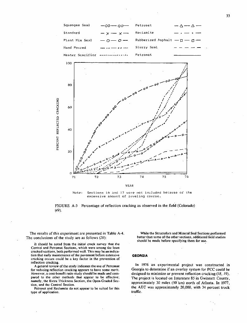
Squeegee Seal
Standard ->.— x- Plant Mix Seal
Hand Poured
Heater Scantier .............
Petroset
Reclamite
Rubberized Asphalt — n - Slurry Seal - - - - -
Petromat
33
100
80
60
20
z
72 73 74 75 76
YEAR
Note: Sections 16 and 17 were not included bcause of the excessive amount of leveling course.
FIGURE A-3 Percentage of reflection cracking as observed in the field (Colorado) (49).
The results of this experiment are presented in Table A-4 The conclusions of the study are as follows (20):
It should be noted from the initial crack survey that the Control and Petromat Sections, which were among the least cracked sections, both performed well. This may be an indica-tion that early maintenance of the pavement before extensive cracking occurs could be a key factor in the prevention of reflection cracking.
A general review of the study indicates the use of Petromat for reducing reflection cracking appears to have some merit. However, a cost-benefit ratio study should be made and com-pared to the other methods that appear to be effective; namely, the Extra Thickness Section, the Open-Graded Sec-tion, and the Control Section.
Petroset and Reclamite do not appear to be suited for this type of application.
While the Structofors and Mineral Seal Sections performed better than some of the other sections, additional field studies should be made before specifying them for use.
GEORGIA
In 1976 an experimental project was constructed in Georgia to determine if an overlay system for PCC could be designed to minimize or prevent reflection cracking (18, 19). The project is located on Interstate 85 in Gwinnett County, approximately 30 miles (50km) north of Atlanta. In 1977, the ADT was approximately 20,000, with 34 percent truck traffic.
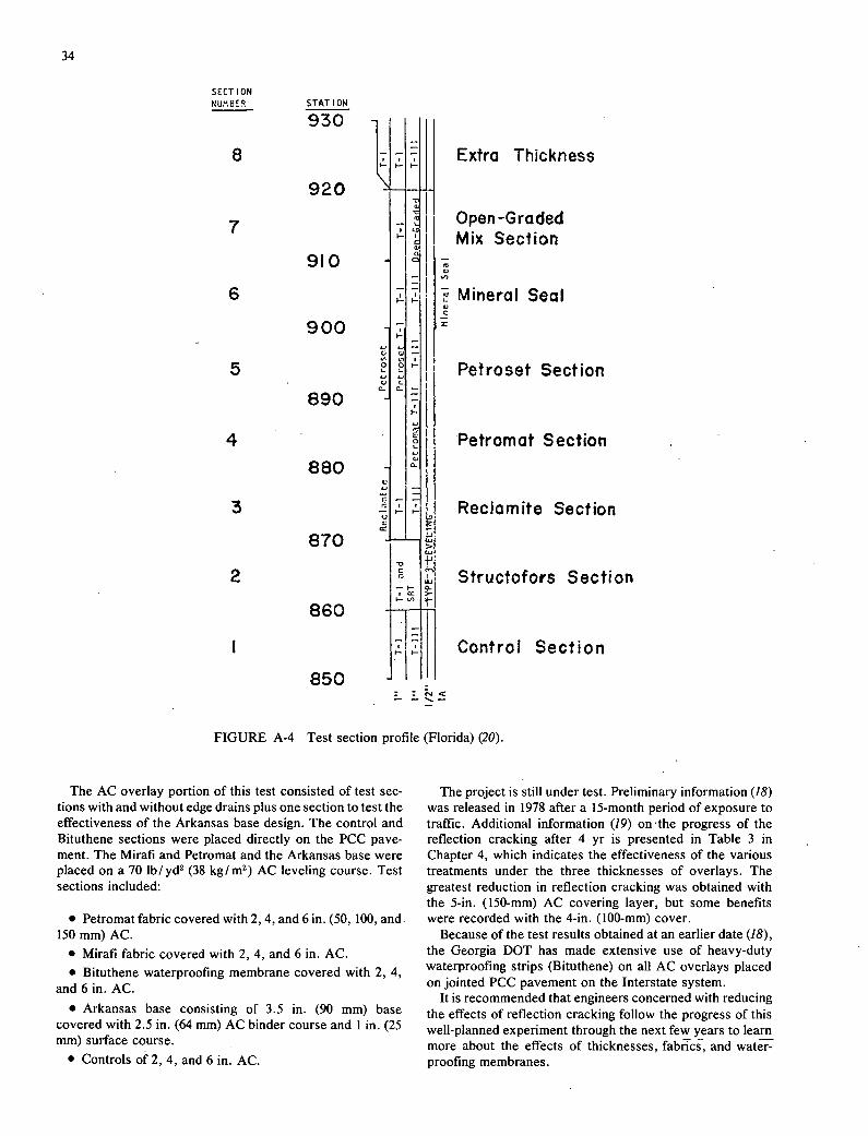
34
SECT ION NtJM8EP. STATION
930
8
920
7
910
6
900
5
890
4
880
3
870
2
860
850
Extra Thickness
Open -Graded Mix Section
a)
Mineral Seal
EA
Petroset Section
Petromat Section
Reclomite Section
Structofors Section
Control Section
-
FIGURE A-4 Test section profile (Florida) (20).
The AC overlay portion of this test consisted of test sec-tions with and without edge drains plus one section to test the effectiveness of the Arkansas base design. The control and Bituthene sections were placed directly on the PCC pave-ment. The Mirafi and Petromat and the Arkansas base were placed on a 70 lb/yd2 (38 kg/rn2) AC leveling course. Test sections included:
Petromat fabric covered with 2, 4, and 6 in. (50, 100, and 150 mm) AC.
Mirafi fabric covered with 2, 4, and 6 in. AC. Bituthene waterproofing membrane covered with 2, 4,
and 6 in. AC.
Arkansas base consisting of 3.5 in. (90 mm) base covered with 2.5 in. (64 mm) AC binder course and 1 in. (25 mm) surface course. -
Controls of 2, 4, and 6in. AC.
The project is still under test. Preliminary information (18) was released in 1978 after a 15-month period of exposure to traffic. Additional information (19) on the progress of the reflection cracking after 4 yr is presented in Table 3 in Chapter 4, which indicates the effectiveness of the various treatments under the three thicknesses of overlays. The greatest reduction in reflection cracking was obtained with the 5-in. (150-mm) AC covering layer, but some benefits were recorded with the 4-in. (100-mm) cover.
Because of the test results obtained at an earlier date (18), the Georgia DOT has made extensive use of heavy-duty waterproofing strips (Bituthene) on all AC overlays placed on jointed PCC pavement on the Interstate system.
It is recommended that engineers concerned with reducing the effects of reflection cracking follow the progress of this well-planned experiment through the next few years to learn more about the effects of thicknesses, fabrics, and water-proofing membranes.

35
TABLE A-4 CRACK SURVEYS (ft2 ) (INTERSTATE 75, FLORIDA) (20)
Tent Scctio Original 8/27/70 () 3/73 (2) jL]j 6 / 75 12/75 1/77
Percent DeviOtion
Ranking by Deviation
Ranking by Existing Condition
Control 934 Cl 100 306 710 1,246 + 33 4 2
Structofors 1,876 Cl & 2 803 1,064 2,668 3,298 + 76 6 6
Rec.Iamite 1,168 Cl 244 2,537 5,469 4,117 + 252 8 7
Petromat 1,590 Cl & 2. 98 295 852 1,102 - 31 1 1
Pctroset 1,606 C2 4,344 4,009 5,679 4,979 4 210 7 8
Mncrai Seal 1,116 0 974 1,280 1,736 1,850 + 66 5 5
Open Graded 1788 Cl 995 374 1,988 1,771 - 1 3. 3
Extra Thickness 2,150 Cl 1,680 1,006 1,357 1,838 - 15 2 4
Original survey taken before overlay. Only minor cracking noted; no attempt was made to measure it. Percent deviation is the percentage of increase or decrease in cracking that occurred between the crack
survey before overlaying and the final crack survey.
NORTH CAROLINA project included testing a 2-in. (50-mm) AC layer over four fabrics covering a full lane, and four strip fabric treatments covering only the crack. In addition, three nonfabric treat-
In 1978 the North Carolina DOT, in cooperation with ments and a normal 2-in. (50-mm) AC overlay were tested,
North Carolina State University, completed a 5-yr NEEP-lO all on a two-lane jointed, unreinforced PCC pavement experiment on US-70 Bypass in Orange County (16). The (Table A-5).
TABLE A-S OVERLAY TREATMENT TYPE AND SYMBOL (16)
Treatment Type Treatment Symbol
Mat course of AP-0 and =5 stone followed by a layer of 1-2 mix. A
Open-graded bituminous seal coat followed by a layer of I-2 plant mix. B
Control section - 2 of 1-2 plant mix. C
Plant mixed mat coat foilowea by a layer of 1-2 plant mix. 0
Mirafi reinforced overlay; fabric continuous over one lane. F1
Structofors reinforced cverlay; fabric continuous over one lane. F2
Petromnat reinforced overlay; fabric continuous over one lane. F3
Fiberglass reinforced overlay; fabric continuous over one lane. r 4
Flirafi strip reinforced overlay; fabric strip over transverse joints and cracks only. S1
Structofors strip reinforced overlay, fabric strip over transverse joints and cracks only.
Petromoat strio reinforced overla,; fabric striP over trar.sverse 3omr.ts and cracks only. S3
Fiberglass strip rainforceo overlay; fabric strip over transverse joints and cracks only. S4

120
C'.)
C.') ') I P 5-I
- . ) ') ') ' C. I) .
U. I
II UI.
U. LIin ./ V) L. I CO
36
The PCC pavement was constructed in 1942 with 11-ft (3.3-m) lanes and transverse contraction joints at 40-ft (3.3-rn) intervals and expansion joints at 120-ft (37-rn) intervals. The condition of the existing pavement was described as follows (16):
The general condition of the test site was very good, par-ticularly in view of the age and traffic history of the pavement. Many of the 11 ft. wide and 30 ft. long panels had few, if any, interior cracks. The transverse contraction joints and expan-sion joints were considered to be 'cracks' while the longi-tudinal joint at the pavement centerline was excluded from the study.
The annual average daily traffic in 1976 was 4,100, includ- ing 947 commercial vehicles of which 123 were semi-tractor trailer vehicles.
The 3.5 miles (5.6 km) of test pavement was divided into six experimental blocks two lanes wide containing 12 experi-mental units in each block. Each of the 12 treatments was repeated in each block.
The relative performance of the various test sections with respect to reflection cracks at the joints is shown in Figure A-S. Also shown are the position and number of replications of each treatment. Additional data as well as an explanation of the statistical treatment are presented in the report on the experiment by Mullen and Hader (16). The general conclu-sions are as follows (16):
Joint Crack Reflection
(1) Joint cracking seems to vary much more with location along the highway than with the different overlay treatments used in this experiment.
The performance of the fabric treatments as a group is not significantly different from the performance of the non-fabric treatments as a group.
Within the group of non-fabrics, treatment D is signifi-cantly (statistically) better than the others (including the con-trol, Q.
Within the group of fabrics, treatments 2 and 3 are significantly (statistically) better than treatments I and 4.
The performance of the best fabric treatment is not appreciably different from the best non-fabric treatment nor significantly different from the control.
The continuous and strip versions of the fabric treat-ments are not significantly different.
None of the foregoing conclusions have changed appreciably for data collected approximately every six months over the last two years.
Interior Crack Reflection
With respect to proportion of original cracking reflected through the overlay, there are no apparent differences be-tween treatments. In particular, the non-fabric treatments seem to do as well as the fabric treatments.
NORTH DAKOTA
In 1972 North Dakota constructed a NEEP-lO experi-mental overlay in the westbound roadway on 1-94 between Buffalo and Casselton. The original road, built in 1948, con-sisted of a 22-ft (6.6-rn) wide thickened-edge plain PCC pave- ment. Widened and overlaid with 5 in. (125 mm) AC in 1963, the section contained a 3 by 6 in. (75 by 150 mm) welded
Fabric
Non-FabPic
.-J - 4 C') C') - .-4 -4 ,-4 C') 4') (j ('.J I I I I I I I I I CO I CO I I CO p (.J C.) I I 160 InU. LI.. I/I U.. 4/) U. 1/) U.. in I.. 1./) U. (/) U.I I Cl) U. /) U.. 4/) LI.. Cl) L /)
140
FIGURE A-5 Reflection cracking at joints for successive experimental units (July 1978, North Carolina) (16).

1000
id
—0-- Emul5ian slurry seal
—a-- Rul,beyized emul.sir slurry seal
197 cour.l +a.ken by a represeta1ive of Philips Pe#øleuni Co.
8000
7000
6000
V 5000
tL. 0
LU .3000 LU
37
wire fabric reinforcing. By 1970 the entire section had deteriorated as described below (50):
Nearly every joint and crack from underlying concrete had reflected through the asphalt. In addition, there were longi-tudinal cracks at or near the location of the longitudinal joints in the mesh reinforcing placed in 1963. The entire roadway exhibited severe map cracking. The transverse reflective cracks were spalling badly and "chuckholes" existed where the asphalt had been eroded. These cracks, spalls and chuck-holes had been repeatedly sealed and patched but with little success.
The 1972 overlay consisted of a 2-in. (50-mm) thick, full-width (37 ft-11.3 m) leveling course and a 1.5-in. (38-mm) thick, 24-ft (7.3-rn) wide wearing course. Seven different ex-perimental sandwich sections were constructed (Table A-6). Section 1 consisted of a layer of AC-treated sand placed on
TABLE A-6 EXPERIMENTAL TREATMENTS BEFORE OVERLAYING (NORTH DAKOTA)
Length Section Treatment miles km
1 0.25 in. (6 mm) of AC treated sand 2.77 4.46
2 Control section 2.80 4.51
3 Structofors fabric 0.18 0.29
4 Petromat fabric 2.76 4.44
5 0.25 in. (13 mm) of plant-mixed seal 2.69 4.33
6 Emulsion slurry seal 2.40 3.86
6A Rubberized emulsion slurry seal 0.19 0.31
5. £ . L
ai 0,l CS U-
FIGURE A-6 Crack count on North Dakota experimental project (50).
38
the existing AC surface before application of the overlay to fill spalled cracks and small surface irregularities. Sections 2-6 were treated with a thin layer of asphalt-treated sand to fill spalled cracks and small surface irregularities before com-pleting the treatment. Section 2 was the control section with-out any treatment other thanthe crack filling.
In Section 3, the Structofors fabric was laid on the surface before overlaying. In Section 4, a nonwoven synthetic fabric, Petromat, was placed on the pavement before applying the overlay. In Section 5, a 0.5-in. (13-mm) thick layer of plant-mixed seal was placed before overlaying. In Section 6, an emulsion slurry seal was placed on the section before over-laying. In Section 6A, a rubberized emulsion slurry seal was applied as a strain-relieving interlayer on the emulsion slurry seal before overlaying.
The conclusions from this extensive project are as follows (50):
The District personnel made a final crack count in November, 1977. At that time the longitudinal cracking
throughout the project was negligible other than the center line, which is expected on asphalt laydowns of this type.
The crack spacing had reduced from an average of some 70 feet between cracks during the first year to a point where it would appear that the reflection cracking follows the concrete pattern plus a crack between each panel for a distance of about 10 feet between the cracks. This pattern seems to run true for all sections and it can be noted that section 2, the control section, has as large a spacing between the cracks as any other section.
The matter of reflection cracks or the elimination of them appears to still be with us. It is doubtful that the present spacing between cracks could be considered an acceptable level.
There are several applications which can be made relative to the data by statistical methods, such as the rate of cracking developing between years, as it appears there was a period where it was quite stable between 1974 and 1975; however, it has accelerated as of this last count. It would appear from all data that the control section is serving as satisfactorily as any of the test sections. The 1976 plotting is not representative as it was counted by a different group.
Attached is a graph of the crack count for each year [Figure A-6]. It appears that none of the products used to reduce reflective cracking worked.

THE TRANSPORTATION RESEARCH BOARD is an agency of the National Research Council, which serves the National Academy of Sciences and the National Academy of Engineering. The Board's purpose is to stimulate research concerning the nature and performance of transportation systems, to disseminate information that the research produces, and to encourage the application of appropriate research findings. The Board's program is carried out by more than 270 committees, task forces, and panels composed of more than 3,300 administrators, engineers, social scientists, attorneys, educators, and others concerned with transportation; they serve without compensation. The program is supported by state transportation and highway departments, the modal administrations of the U.S. Department of Transportation, the Association of American Railroads, the National Highway Traffic Safety Administration, and other organizations and individuals interested in the development of transportation.
The National Research Council was established by the National Academy of Sciences in 1916 to associate the broad community of science and technology with the Academy's purposes of furthering knowledge and of advising the Federal Government. The Council operates in accordance with general policies determined by the Academy under the authority of its congressional charter of 1863, which establishes the Academy as a private, nonprofit, self-governing membership corporation. The Council has become the principal operating agency of both the National Academy of Sciences and the National Academy of Engineering in the conduct of their services to the government, the public, and the scientific and engineering communities. It is administered jointly by both Academies and the Institute of Medicine.
The National Academy of Sciences was established in 1863 by Act of Congress as a private, nonprofit, self-governing membership corporation for the furtherance of science and technology, required to advise the Federal Government upon request within its fields of competence. Under its corporate charter the Academy established the National Research Council in 1916, the National Academy of Engineering in 1964, and the Institute of Medicine in 1970.

I NON-PROFIT ORG. I U.S. POSTAGE I PAID
WASHINGTON, D.C. S
L!ERMIT NO. 42970
N
03
v : - Lum
-4v - Z
Cn
OLUUJ I v•
0<LLJ 0
TRANSPORTATION RESEARCH BOARD National Research Council
2101 ConstItution Avenue, N.W.
Washington, D.C. 20418
ADDRESS CORRECTION REQUESTED