NASA TM-76606
29
NASA 'TECHNICAL MEMORANDUM NASA TM-76606 EXPERIMENTAL STUDY OF TI?E INTERACTION BETEEN THE WING OF A SUBSONIC AIRCRAFT AND A NACELLE OF A HIGH BY-PASS RATIO ENGINE P. Levart (IASA-Ti+76606) BXPBEIdEUTAL STUDY OP T6E 181-27043 IITBBACTIOI BBTClBBl TIE WIlyC OF A SOBSOIBIC AIRCRAFT AND A NACELLE OP A axc;ii BY-PASS RATIO EBlGIlE (lationa1 Aeronautics and Space Unclas Adnioistration) 20 P dC Ac)3/llE A01 CSCL OlA 63/02 26682 Translation of "Etude Experhentale de 1'Interaztion entre une Voilure d*Avion Subsonique Rapide et une Nacelle de F-lcteur a Paut Taux de Pi lution", IN: ACART! Subscnic/Transonic Configuration Aerodynamics, AGARD Conference F'roceedings no. 285, Advisory Group for Aerospace Research and Development, Neuilly-sur-Seine, France (presented at the Fluid Dynamics Panel Symposium), Munich, May 5-7, 1980, p;. 2Q-1 to 23-11.
Transcript of NASA TM-76606

NASA 'TECHNICAL MEMORANDUM N A S A TM-76606
EXPERIMENTAL STUDY OF TI?E INTERACTION BETEEN THE W I N G
OF A SUBSONIC AIRCRAFT A N D A NACELLE OF A HIGH BY-PASS RATIO ENGINE
P. L e v a r t
(IASA-Ti+76606) BXPBEIdEUTAL STUDY OP T 6 E 181-27043 I I T B B A C T I O I BBTClBBl TIE WIlyC OF A SOBSOIBIC AIRCRAFT AND A NACELLE OP A axc;ii BY-PASS R A T I O EBlGIlE (lationa1 Aeronautics and Space Unclas Adnioistration) 20 P dC Ac)3/llE A01 CSCL OlA 63/02 26682
T r a n s l a t i o n of " E t u d e E x p e r h e n t a l e de 1 ' I n t e r a z t i o n e n t r e une Voilure d*Avion Subsonique Rapide e t une Nacelle d e F-lcteur a Pau t Taux de Pi l u t i o n " , I N : ACART! Subscnic /Transonic C o n f i g u r a t i o n Aerodynamics, A G A R D Conference F'roceedings no. 285, Advisory Group f o r Aerospace Research and Development, Neui l ly-sur-Seine, F r a n c e ( p r e s e n t e d a t the F l u i d Dynamics Pane l Symposium), Munich, May 5-7, 1980, p;. 2Q-1 t o 23-11.

zr"z P
-=am
P. i e v a r t
ence i n t r a n s o n i c flow. To t h i s end , a t e s t set-up was developec a t t h e ONERA SjCh wind t u n n e l . The n a c e l l e models r e p r e s e n t a t u r b o f a n by means o f two compressed a i r jets. The s c a l e is U18.5 . a f t e r b o d y t h r u s t and discharge c o e f f i c i e n t s . The wing is l ocabec between t h e s i d e w a l l s c f t h e test s e c t i o n . P r e s s u r e s are measureg th rough 456 h o l e s lcxafed on 8 a i r f o i l s . Drag c o e f f i c i e n t of t h e
The n a c e l l e s a r e f i x e d on a t h r u s t b a l a n c e measu r ing
udmau&d - 8aumwad
d
I I

EXPERIMENTAL STUDY OF THE INTERACTION BETWEEN THe; WIN3 OF A SUBSONIC AIRCRAFT AND A NACELLE OF A HIOH BY-PASS
RATIO ENGINE*
P. Levart** *@*/20-1
SUMMARY
The oncoming of a new generat ion of dubsonic t r anspor t air- craf t (with s u p e r c r i t i c a l w i n g and high bpp88S rat io turbofans) has led t o an experimental study o f wing-nacelle-Jet-pylon l n t e r t e r - ence i n t ransonic flow. To t h i s end, a test set-up h a s been devel- oped a t t h e ONERA S3Ch wind-tunnel.
The nace l l e models represent a turbofan by means of two com- pressed air jets. a t h r u s t balance measwing afterbody t h r u s t and discharge coeffl- c i en t s .
The s c a l e is 1/18,5. The nace l l e s are f ixed on
The wing is located between t h e sidewalls of t h e test sec t ion . ?ressures are measured through 456 holes located on 8 a i r fo i l s . Drag coe f f i c i en t o f t h e wing is obtained by wake survey.
The following parameters can vary: - wlng/nacelle posi t ion; - upstream Mach number (from 0.3 t o 0.8); - j e t pressure r a t i o ; - with/without pylon; - t y p e of nacel le .
@ AOARD Conference Proceedings no. 285. SUbSOnlC/Tran8OniC Con- f igu ra t ion Aerodynamics. Panel Symposium a t t h e Munich I n s t i t u t e of Twhnology ( f l l e g i b l e ) ,
Office National d'Etudes e t de Recherches Aerospatiales, 23, avenue de l a Division Lsclerc, 92320 CHATILLON - FRANCE
Paper preaented a t t h e Fluid Dynamics
* @
*** Numbers i n margin ind ica t e pagination of f o r e l g n t e x t .
1

W i n g n a c c l l e ' i n t e r f o r e n c e can thuu be studied by means of total thrust-drag ana lgs i s , a8 a funct ion of the p r P I O U 8 paramaeters.
The test set-up is desorlbed, and example8 of results a m pre= sented i l l u s t r a t i n g t h e p o s 8 l b i l l t ~ e 8 of t h i s uet-up.
1. INTRODUCTION 120-2
The problem of nacelle-wing i n t e r a c t i o n on c i v i l i a n aircraft bas been di8cUSSed ov@r t h e l a a t few years by a U t b O P 8 [l-133. Only a few studies con side^ the case of s u p e r c r i t i c a l w i n g s , whiab could be more s e n s i t i v e t o l n t e ~ a c t i o n s tban classical wings, or t h e case of nace l l e s of a o t o r s witb a high d i l u t i o n rate, whlcb bave a large dimenslon blower, which means t b a t t h e nacelle has t o be very c lose t o t h e wing.
A r a t h e r general s tudy of t h e nacelle-Jet wing i n t e r a c t i o n was, therefore , undertaken i n a wind tunnel i n order t o develop bash information required f o r s e l e c t i n g t h e r e l a t i v e nacelle-wing po8i- t l o n for t h i s t y p e of configuration.
2. METHOD AND TEST EQUIPMENT
The tests were performed i n the S3 wind tunnel a t Chalais- Meudon at t h e ONERA.
2.1 S3 wind tunnel of Chalals-Meudon
This is a aubsonlc/transonic wind tunne l which is continuous and revers ib le . The oross sec t ion is quasi-octagonal. Tbe dimen- s ions of t h e tes t sec t ion are the following: Height 0.8~1, width 0.9m. Diameter of t h e inscr ibed c i r c l e = lm (area 0.66 m The t o t a l length of t h e t e s t s ec t ion l a 1.75~1 and t h e usefu l l eng th cor- responds t o the dimensions of t he portholes: 0.60m. The generat- ing pressure i s c lose t o t h e atmospheric pressure. The generating temperature increases as a funct ion of Mach number, from ambient
2
2

temperature up t o 340 K approximately for l4 - 0.9.
Tbe lateral walls are solid and parallel (these are t h e port- holes ).
For t h i s study, t h e upper and lower walls are solid, 80 that t h e incidence (angle) induced by wall effects is small. t e a t s i n an empty wind tunnel carried out fo r Mach numbers between 0.3 and 0.9 gave s a t i s f a c t o r y r e s u l t s . discussed here, t h e Mach number upstream never exceeded 0.80.
In i t ia l
Durlng t h e detailed test8
2.2 Rear body weighing balance
Host of t h e experimental s t u d i e s of t h e nacelle-wing i n t e r a c t - ion carried out up t o t h e present t h e were deslgned t o eva lua te the inf luence of t h e presence of t h e propulsion n a c e l l e (simulated more o r less) on t h e wing c h a r a c t e r i s t i c s . f ea tu re s of t h e present study is that i n add i t ion , w e measured t h e inf luence of t h e presenhe of t h e wing on t h e engine performance a8 a funct ion of var ious parameters. For t h i s purposes t h e propulsion nacelle is placed on a weighing balance for t h e rear body which i s p a r t i c u l a r l y designed for steadying t h e rear body of engines a t a h i g h d i l u t i o n rate.
One of t h e o r i g i n a l
The diagram is shown i n Figure 1.
The p r i n c i p l e I s t h e p r i n c i p l e of an upstream s t i n g &ere t h e model t o b e s tud ied is f ixed downstream of an a x i a l cane which is used t o provide compressed a i r f l u x and f o r t h e pressure measurement tubes. and contains a dynamonetric bar e q u i p p e d with s t ra in gauges.
The balance used is a s i n g l e component balance (axial t h r u s t )
The nace l l e model c o n s i s t s of a par t which is not weighed ( i n l e t a i r f a i r i n g up t o a ooupling p iece) and a weighed p a r t (rear body proper 1.
3

In tba f i r a t version, t b e connection between the weighed part and the non-weighed gapt -8 provided by &n annular dynamometer located i n tho upstreani part or tbe nacelle. The rirst test8 showed d i f t i c u l t i e s wi th t h i s armurgement. The space allowed for t h e dyna- mometer was t i g h t In tbe test, mechanical and t h e m 1 stresses deveioped 80 t h a t a precise measurement of tbe t k u s t became irapoaslble.
and it was ancbored t o not enough material.
After t b i s , the dynaaPolPeter was moved to the upstream point of t b e cane and t h e suspension between the w@ighed part md tbe non- weighed p a r t is divided by an annular roller.
The cont ro l of t h e boundary layer alorrg the sting upstream or tbe nace l le is provided by two devices whicb operate successively and slmultaneously: One tangential blowing device and on@ aspipa- t i o n device t o t h e r i g h t of t h e I n l e t f a i r ing . Tbese two devices allow one t o reduce t h e tbickness of t h e boundary layer over the rear body and t o reproduce a real is t ic external flow.
2.3 T e s t models
2.3.1 Wine;
The wing model is shown i n Figrare 2. T h i s is a wing w i t h a cbord of 220 m wi th a r e l a t i v e thickness of 12.5$. It is i n s t a l l e d wi th a sweepback angle of 28O between t h e lateral walls of t h e wind tunnel. The p r o f i l e is an SNIAS p r o f i l e of t h e supe rc r i t i ca l type. The wing is twisted l i nea r ly by 3 O along t h e width of t h e t e s t sec- t ion . i n t o 8 sections. side and 27 taps on t h e bottom side.
The mdel I s equipped wi th 456 wall p r e s s u ~ e taps d i s t r ibu ted POP each sect ion there are 30 taps on t h e top
/20-3 In addi t ion, the drag of t h e wing can be determined from sound-
ings of t h e wake. Stagnation presswe explorations were performed fo r s i x chord posi t ions corre8ponding t o t h e wing sect ions carrying t h e wall pressure taps.
4

Wake pressure and w a l l p ressures m e not acquired simultan-
It is, eously. The rake remains i n s t a l l e d in t h e wind tunnel ( i n t h retracted s ta te ) dur ing t h e e n t i r e du ra t ion of t h e te8t. therefore , Important t o v e r i f y t h a t t h e presence of a rake does not not iceably inf luence t h e p r e s s u ~ e s measupob over t he wing. 3 shows a presswe difs t r ibut lon measured over t h e w i n g w i th and without a rake downstream.
Figure
The tests WCFe PePfOmed by m t i f i c i a l l y tPigg@Phg the trans- i t i o n of' t be boundary l a y e r using carborundum gra ins glued near, the leading edge of t he wing, on the tog side and on t h e bottom side. Tbe t r a n s i t i o n band wi th a w i d t h of 3 nuti is placed 13.6 mm frosa t h e lead ing edge.
The wing I s f ixed between t h e walls of t h e test aec t lon , but i ts incidence angle can be changed, as can i t s a l t i t u d e and its long- i t u d i n a l pos i t ion .
2.3.2 Nacelles
The nace l l e models were provided by SNECMA. They f a i t b f u l l y represent at a scale of 1/18.5$ s o l u t i o n s considered for t h e rear body of an engine with a high d i l u t i o n rate, t h e GPM 56.
The t h r u s t is obtained from two compressed a i r j e t s which simulate t h e engine f lux .
Three models of n a c e l l e s were tested. They are shown in. Figure 4. Two nace l l e s have confluent f lux . One is short (PCC) and the o t h w I s long (FCL). f l u x (PSC).
The t h i r d one i s of t h e sho r t kind w i t h separate
They are equipped w i t h presswe taps r v e r t h e upper meridian of t h e ex te rna l f a i r i n g .
2.3.3 Pylons
5

The mast which connects t h e propulsion nace l l e t o the wing plays a v e ~ y Important r o l e i n t he wing-nacelle In te rac t ion . I n any experimental study it i a , therefore , important t o represent these ntaats i n a r e a l i s t i c manner. The mas% was represented f o r four configurat ions, two with t h e PCL nace l le , one wf tb t h e FCC nacelle and one w i t h the FSC nacel le .
The masts are o r i g i n a l l y connected t o t h e wing. Since t h e Racelles are weighed, there can be no mechanfcal contact between t h e mast and t h e nacel le . T h i s explains the space between t h e nacelle and tbe mast.
The complete i n s t a l l a t i o n fo r t h e nacelle-wing i n t e r a c t i o n study i s shown i n Figure 5.
2.4 Tested configurat lons
Tests were performed i n three s tzges . a ) a f t e r determining t h e incidence angle t o use we studied
the c h a r a c t e r i s t i c s of t h e wing alone i n t h e wind tunnel f o r d i f f e r e n t Mach numbers.
b) s tudy of t h e t h r u s t and the ex terna l pressure d i s t r i b u - t i o n s of t h e t h ree nace l les , tested alone I n t h e wfnd t unriel .
c ) s t u d y of t b e nacelle-jet-wing-pylon in t e rac t ion w i t h a simultaneous test of t h e wing and t h e axis.
This lat ter p a r t then cons i s t s of several pa r t s : - ir.t'luence of t h e delay r a t e of t h e j e t engine on t h e wing
- influence of upstream Mach number - influence of t h e r e l a t i v e wing/nacelle pos i t ion - influence of t h e nacelle type - Influence of t h e presence of the pylon
character 1st IC s
6

The in f luence of t h e delay rate was atudied for values between the natwal flow rate ( t h a t is, which simulates the Jet emerging f r o m a hollow nacelle) up t o o r u i s e eonditiona.
The upstream Mach number varies between 0.3 and 0.8.
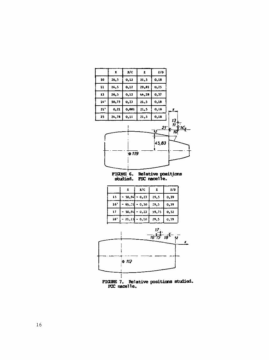
For each of t h e nacelles FSC and FCC, severa l r e l a t i v e posi- t i o n s were s tudied , hor izonta l and two or three along t h e vertical . me defined I n Figupes 6 and 7. r e l a t i v e pos i t i ons , both with t h e mast. i n Figure 8.
They def ine a T w i t h three pos i t i ons along the
The n a c e l l e FCL was tested for t w d These pos i t i ons
These pos i t i ons me 3 e f i ~ d
The study of t h e in f luence of tbe presence of t h e pylon was performed for one r e l a t i v e pos i t i on w i t h t h e nacelle FSC (number 21 ' ) and another one w i t h t h e n a c e l l e FCC (number 1 8 r ) .
3. EXAMPLE OF RESULTS
The present test conf igura t ion allows one t o acqui re a great deal of information about the nacelle-wing In t e rac t ion : Pressure d i s t r i b u t i o n over t h e wing and over t h e nace l l e s , measurement of t h e t h r u s t and t h e flow ra te c o e f f i c i e n t of t h e engines. For each configuration it is then poss ib le t o determine a thrust-drag g loba l
balance. w i th t h e i n s t a l l a t i o n .
For t h e ana lys i s , t h e results were cor rec ted f o r wall e f f e c t s
The r e s u l t s which follow g ive an idea of t h e poss ib i l i t i es
/20-4 - using t h e theory discussed i n [14] by u s i n g a constant incidence angle and Mach number within t h e test sec t ion .
For each sec t ion , t h e aerodynamic c o e f f i c i e n t s were obtained by i n t e g r a t i o n cf t h e presswe measurements. The global C, and C,
'lithe waKe soundings were performed during a second t e s t sey ie s , When t h i s present document was edi ted, %be resu l t s of t h e C, of' t h e wake were not y e t ava i l ab le and t h e evaluat ion of t h e C, wasper- formed from t h e i n t e g r a t i o n of pressures over t h e wing,
7

values of t h e wing were obtained by i n t eg ra t ing the C, and the 6, l o c a l values as a funct ion of chord. It 1s found t h a t t h e global coe f f i c i en t s only a f f e c t t h e pa r t of t h e wing between t h e two ex- treme pos i t ions of t h e pressure t a p .
3.1 Influence of t h e J e t
A simple way of represent ing complete configurat ions of wings equipped wi th nace l les now i n use c o n s i s t s of u s ing a hollow nace l le through which a na tu ra l a i r flow rate c i r c u l a t e s . It is then i n t e r - e s t i n g t o ve r i fy whether t h i s representatfon is not too simplistic, by t e s t i n g t h e wing plus nace l l e combination f o r var ious air flow rates, from t h e na tu ra l flow r a t e up t o t h e Plow rate which repre- s en t s t h e crt l ise t h r u s t . T h i s i s done by comparing t h e l o c a l and global aerodynamic coe f f i c i en t s . Figure 9 shows t h a t a s u b s t a n t i a l va r i a t ion i n the delay flow rate of t h e j e t results i n a very small va r i a t ion of Cx and a moderate one i n Cz. These r e s u l t s confirm t h e ones obtained by El-Ramlg and Rainbird [ l5] f o r a s i m i l a r configura- t ion.
These t e s t s show t h a t it i s I n t e r e s t i n g t o use permeable nace l les when we are only In te res ted i n t h e wing c h a r a c t e r i s t i c s .
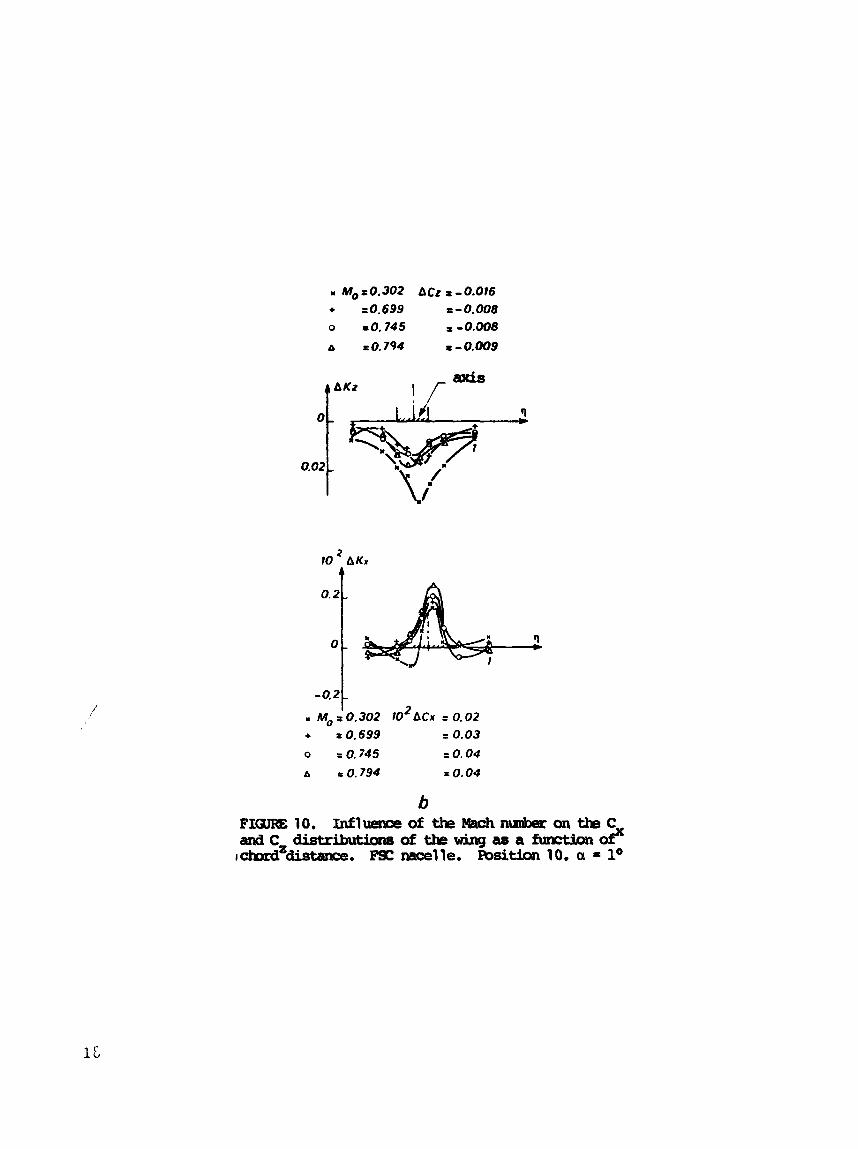
On the o ther hand, t h e t h r u s t s obtained w i t h a na tu ra l flow rate and f o r t h e c ru i se flow rate are very d i f f e r e n t as a r e t h e pressure d i s t r i b u t i o n s over t h e nace l le f a i r i n g , e spec ia l ly over t h e cover of t h e first motor which is d i r e c t l y subJected t o t h e inf luence of t h e J e t on t h e l i f t and t h e drag of var ious sec t ions i n t h e chord d i r e c t i o n f o r d i f f e r e n t Mach numbers.
I n addi t ion, Figures 11 and 1 2 show t h e inf luence of t h e delay flow r a t e of t he j e t s on t h e pressure d i s t r i b u t i o n s over t h e wing, f o r two chord p o s i t i o n s . One of them (Figure 11) was very c lose t o t h e a x i s of the j e t and t h e second one was f a r t h e r away (Figure 12). i s completely negl ig ib le .
In t h e la t ter case, theinf luence of the delay r a t e of t h e j e t
8

3.2 M&eelle-asing I n t e r a c t i o n on the pressure d i s t r i b u t i o n s
Figure 13 shows t h e effect of t h e preerence o f t h e wtng on t h e pressure d l s t r l b u t l o n s over t h e nace l l e f a i r i n g FSC f o r two rr4.'- numbers. The Inf luence is s u b s t a n t i a l , e spec la l ly a t Mo = . {94.
Figures 14 and 15 show t h e Inf luence of t h e presence of t h e nace l l e FSC on t h e pressure d f s t r i b u t i o n s over t h e wing f o r two chord values. The effect I s pronounced f o r t h e c e n t r a l s w t i o n (Figure 1 4 ) which I s not surproising. It is also t h e same for t h e more d i s t a n t s ea t ion (Figure 15). The e f f e c t i s translated espe- c i a l l y f o r t h i s chord d i s t ance by a movement upstresun of t h e shock on t h e tops ide of t h e wlng.
3.3 Influence of trJe r e l a t i v e wing-nacelle p o s i t i o n
3.3.1 Influence of t h e hor izonta l pos i t i on
Figure 16 shows t h e v a r i a t i o n of' C x of t h e wing and t h e t h r u s t c o e f f i c i e n t of t h e nace l l e caused by a hor izonta l displacement of t h e wing and nace l le .
We f ind t h a t t h e drag of t h e wing and t h e t h r u s t of '"he nace l l e are increas ing func t ions of t h e r e l a t i v e d is tance . The g loba l in te r - ac t ion balance represented In Figure 16 i s always favor*;lble and shows t h a t t h e best pos i t i on is t h e 21' which i s where t h e wing and t h e nace l l e are c l o s e s t t o ene another.
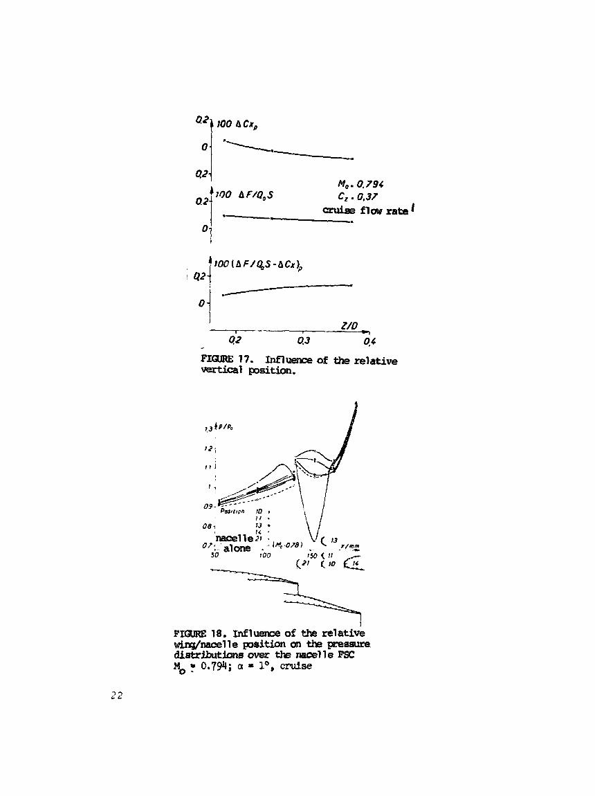
3.3.2 Influence of t h e v e r t i c a l pos i t fon
Figure 17 shows t h a t when t h e wing i s d isp laced v e r t i c a l l y away from t h e nace l le , t h e drag o f t h e wing and t h e t h r u s t of t h e nace l le decrease s l i g h t l y . The g loba l i n t e r a c t i o n balances which I s always favorable, i n d i c a t e s t h a t t h e most d i s t a n t pos i t i on I s
9

t h e bes t but t h e change from t he o the r posit ion8 98 only small.
The r e s u l t s of t h e two paragraphs above confirm those i n [163*
3.3.3 Study of pressure d i s t r i b u t i o n s over t h e nacelle
Figure 18 shows t h e v a r i a t i o n of t h e pressures over t h e nace l l e f o r var ious r e l a t i v e pos i t i ons s tud led f o r c r u i s e flow Pate. The p r e s s w e l e v e l Over t h e secondary f a i r i n g increases when one moves t h e wing a m y from t h e nace l l e ho r i zon ta l ly o r v e r t i c a l l y t o posi- t i o n 21 ' , except f o r t h e last pressure tap.
3.4 Influence of t h e nace l l e t y p e
The two nace l l e t y p e s FSC and FCC were compared w i t h t h e wing i n a similar pos i t i on , t h a t is for two d i s t ances of t h e c e n t r a l p r o f i l e leading edge of t h e wing from t h e re ference plane of models of i d e n t i c a l nace l les . R 0 - 5
Compared t o t h e FSC nace l l e i n pos i t i on 10 , nace l l e FCC br?.ngR about a s t rong reduct ion i n t h e drag. The presence of t h e wir ;
t h e same e f f e c t on t h e t h r u s t of t h e two nace l l e s which gfveP a mre favorable globs1 thrust-drag balance f o r t h e FCC nace l l e (see Figure 19)
3.5 Inf luence of t h e presence of t h e pylon
Two c o n f l g s a t i o n s which only differed by t h e presence o r t h e The n a c e l l e i s t h e same (FSC) absence of t h e pylon were compared,
as i s t h e r e l a t i v e wing-nacelle pos i t i on (21'). The fncidence, t h e
Mach number upstrean (0.794) and t h e d e L y flow rate of t h e j e t s are a l s o t h e same.
Figure 20 shows t h e d i f f e rence between t h e pressure d i s t r i b u - t i o n over t h e wing for rl 9 0.456. We f i n d t h a t l o c a l l y on t h e bottom
LO

side, t h e presence of t h e pylon provokes a s u b s t a n t i a l acce le ra t ion of t h e Plow.
When one moves away i n t h e chord d i r e c t i o n , a t tl 0 (Figure 2 l ) , t h e inf luence of t h e presence of t h e pylon on t h e preseure dis- t r i b u t i o n i s negl ig ib le .
4. DISCUSSION OF RESULTS
The r e s u l t s presented here p * l L l consider aga in t h e l o c a l and
They have t o be confirmed by t h e determination o f t h e C, global C, values obtatned by in t eg ra t ion of t h e pressures over t h e wing. obtained by sounding of t h e wakes of t h e wing. The t es t s were per- formed during a second test campaign and t h e r e s u l t s hare not ye t been analyzed.
Also, t h e study of t h e r e l a t i v e wing-nacelle pos i t i on was per- formed without a pylon. The importance of t h e pylon, emphasized i n Sect ion 3.5, w i l l r equ i r e t h e study of t h e nnesence of t h e pylon. Unfortunately, t h e t y p e of i n s t a l l a t i o n useL ,,ere i s not very prac- t i c a l for such a study (one has t o bui ld a pylon shape f o r ea2h pos i t ion of t h e nace l l e ) .
A s far as t h e masurement of t h e t h r u s t L f ';he rear body is concerned, t h e conflgurat ion WPS calibrated using a c a l i b r a t i o n nozzl- of t h e ASME t y p e whit;- i 3 smwn i n Figure 22. The tests were performed f o r two ejrternal Mach numbers and erpansior flow rates which var ied and these were compared w i t h r e s u l t s obtained w i t h IL
similar nozzle tested on t h e dynalpy BD2 tes t stand of t h e ONERA a t Modsne. Also, a formula proposed by ASME was used. Figure 23 sum- marizes t h e comparisons and shows tha t ; t h e agreement is good, both f o r t h e I sen t ropic t h r u s t coe f f i c i en t r l l ~ and t h e flcw ra te c o e f f i c i e n t CD, which va l ida t e s t h e r e l a t i v e r e s u l t s of t h e t h r u s t .
11

5 CONCLUSION
A nacelle-wing fr.teractfon t e a t conrfgwation has Been devel- oped fo r the S3Cb wind tunnel of the OWERA for subsonic configuxv$- tions t o be used in the future. That Is, we me t e 8 t i n g t h e supw- C r i t h 8 3 1 Wing and double flU swine Racelles with a high d i lu t ion Pat@. The CbaPaCtePi8 th8 O f the Wlm dstePlahd bat ~i~@asupftng: wall presswe d i s t r fbu t lona OR eight sec t ions , by using wake sound- ings downstreara of the seet lons. of' an upstream Ving wbieh earroics compress& a i r flow. of t h e rew bod3 and tke flow rate coe f f i c i en t of' the nozzle are measured. carried out:
The nacelles &.?e placed downstrem The thrust
The study of the effect of various par-ters can then be
- expansion r a t i o of the j e t engine; - upstream Mach number; - r e l a t i v e wing-nacelle posi t ion; - nace l le type ; - presence of t h e pylon.
The resul ts presented i l l u s t r a t e t h e mult iple p o s s i b i l i t i e s of
- on t h e one hand, t o f a c i l i t a t e our understanding of i n t e r -
- on the o ther hand, t o va l ida t e t h e corresponding theo re t i -
t h i s i n s t a l l a t i o n which can be used i n t h e fu ture :
ac t ion phenomena;
c a l p red ic t ion methods.
12

NOTATION 120-6
1/2 cbrd of t h e wfng cplord of t h e wing nozrle flow rate coe f f i c i en t drag coe f f i c i en t presswe drag coe f f i c i en t of t h e rring car ry ing t h e press- ure taps lift coe f f i c i en t of tbe part of t h e wing car ry ing the pressure t aps diameter of tbe nace l l e f n t h e secondary e3 ec t ion plane t b r u s t coe f f i c i en t of t h e nace l le pressure coe f f i c i en t +v l o c a l drag coe f f i c i en t of one wing sec t ion l o c a l l i f t coe f f i c i en t of one wing sec t ion upstream Mach number l o c a l s t a t i c pressure reference s t a t i c pressure
p i p i 0
P i s
QO
RN
s x
X
Y
z a
l o c a l etagnat ion prerrwre reference generat ing pmss-
stagnat ion presswe of secondary j e t reference dynamic plpeisure
Reynolds number measwed in t h e c a l i b r a t i o n aorrsle throat wing reference area abscissa meawred ovef) one meridian of tbe nace l l e (o r ig in for the nace l l e referenee plane) abscfssa of the seconiiary eJec t ion plane (B.A. ori- g in of t h e c e n t r a l w i n g chord ) chord d is tance (or ig in : sectfon no. 8 of t h e w i n g ) ve r t i c a l d i s t ance ( c r i g l n : test sec t ion a x i s ) incidence angle of wiirg
w e
a - Q.7p-8
~
0 = reduced chord
‘p c i e n t i sen t ropic t h r u s t coef f i -
ABBREVlAT IONS
FCC short confluent f l u x nace l le FSC short separa te f l u x nace l le FCL long confluent f l u x nace l le


Ij-qqqz-1 26.5 0.12 29.85 0.25
13
14'
56.5 0.12 64.58 0.37
50.73 0.23 21.1 0.18
16

I I e* / e 1.0 1.5 2.0
17
rn Mo=0.302 ACZ t-0.016 + =0.699 t-0.008 0 PO.745 r -0.008
8 r0.798 t - 0.009
10 ' h K r 4
2 rn Mo = 0,302 10 ~ C J I = 0,02 + ~ 0 . 6 9 9 = 0.03
0 -0,745 z 0.04
A ~ 0 . 7 9 4 t 0.04

m E 12.
wing. M = 0.794; a = lo; 17 = 0. Nacelle PSC
l n f l m of the e2cpmhn ratio of t h @ j e t m t h E ? ~ ~ ~ s t r i b u t i o n s o \ r e a c ~
in p o s i t h 10.

131
/ I
I with P10 Imcelle-.in cruise !
rtK, Mgure 15. Influence of the presence of the nacelle on the distrfbutbn of p r e s s p over the wing. % = 0.794; a = l ; q = O
20

FIGURE 16. horizontal position.
Influence of the relative
2 1
421 100 hCx,
12
1 )
t
09 1 I . \ I
2 2

+mmE 20. Influenr=e of the pms@nce of the gylm on tb pressure distribu= t icm over t k wing M = 0.794; a = lo; ~0.456. Nacelle &ition 21 '. Cruise flow rate.
2 3

t K I f
FI- 21 . Influence of the presence of the pylm on t k pressme distribu- tion over the wing. M = 0.794; a = lo r, = 0. m t t e FSC g8sition 21'. Cruise flow rate
S&ti&S static s\lpports rake fa' cavity ham
FIGURE 22. 53 Chalais reference mzal e instal lation
24

+ ONERA 802 Modane 9 ONERA SJ Chelais
-- ASME

REFERENCES
1.
2.
3 .
4.
5 .
6.
7 .
F.
9 .
10.
11.
12.
13.
Kho, '1. G. Wind-tunnel measurements on t h e i n t e r f e r e n c e between a j e t and a wing, l o c a t e d o u t s i d e t h e j e t . Par t I. NLR TR 77009 U.
Zandbergen. Expe r imen ta l i n v e s t i g a t i o n of t h e aerodynamic c h a r a c t e r i s t i c s of a wing i n p r o p u l s i v e jets. NLR TR 77081.
Wittmann, M. and F i s c h e d e r , W. I n s t i t u t f u e r Luft-und Raumfahrt , TI-? Aachen. I n v e s t i g a t i o n of t h e i n t e r a c t i o n between e n g i n e n a c e l l e and wirlg. DLR FB 'T4-32, 1974.
Swan-Sigal la . The problem of i n s t a l l i n g a modern h i g h bypass eng ine bn a t w i n j e t t r a n s p o r t a i r c r a f t . A G A R D CP-124.
Kc.,ney. Ai r f ra rne /propuls ion sys tem i n t e g r a t i o n a n a l y s i s u s i n g t h e p r o p u l s i o n s i m u l a t o r t e c h n i q u e . A G A R D CP-71-71.
c e l l u l e d e 1 'A i rbus e n c r o i s j e ' r e S i m u l a t i o n e n s o u f f l e r i e (Bordeaux) ( I n t e r a c t i o n o f GE CP6 50 e n g i n e j e t s w i t h t h e ATRBUS a i r f r a m e under c - u i s e c o n d i t i o n s . Wind t u n n e l s i m u l a - t i o n (BordealJx) AAAF 1974 .
S a i z . I n t e r a c t i o n d e s j e t s d e s r g a c t e u r s GE C176 50 s u r l a
P a t t e r s o n , J. A wind t u n n e l i n v e s $ i g a t i o n of j e t wake e f f e c t o f a h:gh bypass e n g i n e on wing n a c e l l e i n t e r f e r e n c e d r a g o f a s u b s o n i c t r a n s p o r t . N A S A TND 4593.
Miinniksms - Jaarsma. J t t i n t e r f e r e R c e o f a podded e n g i n e i n s t a l l a t i o n a t c r u i s e c o n d i t i o n s . A G A R D C? 150 .
Krenz, G . Airframe e n g i n e i n t e r a c t i o n f o r e n g i n e c o n f i g u r a t i o n s mounted above t h e wing, P a r t I : i n t e r f e r e n c e between wing and i n t a k e / j e t . AGARD C P 150.
Ewald, B. ? a r t 11: e n g i n e j e t s i m u l a t i o n problems i n wind- CLtnnel t es t s . A G A R D CP 150.
Raney, 3. J., Kurn, A . G . Wind t u n n e l i n v e s t i g a t i c n o f j e t i n t e r f e r e n c e f o r iinderwing i n s t a l l a t i o n o f h i g h bypass r a t i o eng ine RAE TR 63049 1969.
Pauley , i;. InterTm n o t e on t e s t s w i t h a wing mounted I ' m n a c e l l e w i t h t h e f a n j e t s i m u l a t e d by c o l d a i r blowing and a l t e r n a t i v e l y by a gas g e n e r a t o r 2hroud. ARCC? 1111.
Paters2r . F l e c h n e r . J e t wake o f a hit'? bypass e n g i n e on wing n a c e l l e i n t e r f e r e n c e d r a g o f a s u b s o n i c t r a n s p o r t a i r p l a n e KASA TF: D 6067 (1970.

1 4 . P i n d z o l a , M., Lo, C. F. Boundary i n t e r f e r e n c e a t s u b s o n i c speeds i n wind t u n n e l s w i t h v e n t i l a t e d walls. P.EPC TR 69 .47 - May 1969.
15. E!. Ramly, Z., R a i n b i r d , V. 2. E f f e c t of s imula t ed j e t e n g i n e s on t h e f l o w f i e l d beh lnd a swept Sack wing. J o u r n a l o f A i r c r a f t Vol. 1 4 no. 4 , A p r i l 1977, p . 343-3Qi7 .
16. A ld r idge , S. E . , Nye , J. L. Expe r imen ta l r e s u l t s of h l g h !,;;pass r a t i o t u r b o f a n and wing aerodynamic i n t e r f e r e n c e AGARD CP 71.