NASA Technical Memorandum · coil where the ratio of coil diameter to sample diameter is smaller....
21
NASA Technical Memorandum NASA TM-82565 ELECTROMAGNETIC LEVITATION COl L FABRICATION TECHNIQUE FOR MSFC CONTAINERLESS PROCESSING FACl LlTlES E. C. Ethridge, J. Theiss, P. A. Curreri, and G. J. Abbaschian Space Science Laboratory November 1983 Natio~al Aeronaut~cs and Snace Adml~lstration George 6. Marshall Space Flight Center MSFC - Form 3190 (Rev. May 1983) https://ntrs.nasa.gov/search.jsp?R=19840010467 2020-04-03T06:59:17+00:00Z
Transcript of NASA Technical Memorandum · coil where the ratio of coil diameter to sample diameter is smaller....

NASA Technical Memorandum
NASA TM-82565
ELECTROMAGNETIC LEVITATION COl L FABRICATION TECHNIQUE FOR MSFC CONTAINERLESS PROCESSING FACl LlTlES
E. C. Ethridge, J. Theiss, P. A. Curreri, and G. J. Abbaschian Space Science Laboratory
November 1983
Nat io~al Aeronaut~cs and Snace Adml~lstration
George 6. Marshall Space Flight Center
M S F C - Form 3190 (Rev. May 1983)
https://ntrs.nasa.gov/search.jsp?R=19840010467 2020-04-03T06:59:17+00:00Z

Electromagnetic Levitation Coil Fabrication Technique I for MSFC Containerless Processing Facilities I
George C. Marshall Space Flight Center Marshall Space Flight Center, Alabama 358 12
National Aeronautics and Space Administration Washington, D. C. 20546
Technical Memorandum
1.1, SPONSORlNG AGENCY CODE
I
15. SUPPLEMENTARY NOTES
Prepared by Space Processing Division, Space Science Laboratory, Science and Engineering. I I
The technique described in this report has facilitated the more reproducible fabrication of electromagnetic levitation coils. A split mandrel has been developed upon which the coil is wound. After fabrication the mandrel can be disassembled to remove it from the coil. Previously, it required a full day to fabricate a levitation coil. The success rate for a functional coil was still only 50 percent. With the new technique described in this note about eight coils may be completed in one day and 1
Electromagnetic levitation Electromagnetic coil Containerless processing
Unclassified - Unlimited
- pp - -- hlSFC - Form 32927*y 1969)
For sale by National Technical Information Service. Springfield, Virginia 221 61


TABLE OF CONTENTS
Page
INTRODUCTION . . . . . . . . . . . . . . . . . . . . . . . . . . . . . . . . . . . . . . . . . . . . . . . . . . . . . . . . . . . . . . . . 1
COIL DESIGN . . . . . . . . . . . . . . . . . . . . . . . . . . . . . . . . . . . . . . . . . . . . . . . . . . . . . . . . . . . . . . . . . . 1
COIL FABRICATION . . . . . . . . . . . . . . . . . . . . . . . . . . . . . . . . . . . . . . . . . . . . . . . . . . . . . . . . . . . . 2
CONCLUSIONS . . . . . . . . . . . . . . . . . . . . . . . . . . . . . . . . . . . . . . . . . . . . . . . . . . . . . . . . . . . . . . . . . 3
REFERENCES . . . . . . . . . . . . . . . . . . . . . . . . . . . . . . . . . . . . . . . . . . . . . . . . . . . . . . . . . . . . . . . . . . 15
BIBLIOGRAPHY . . . . . . . . . . . . . . . . . . . . . . . . . . . . . . . . . . . . . . . . . . . . . . . . . . . . . . . . . . . . . . . . 15
iii

Figure Title
. . . . . . . . . . . . . . . . . . . . . . . . . . . . . . . . . . . . . . . . . . . . . . . . . . . . 10kW Lepelgenerator
Laboratory vacuum system used for containerless processing experiment development . . . . . . . . . . . . . . . . . . . . . . . . . . . . . . . . . . . . . . . . . . . . . . . . . . . . . . . . . . . .
. . . . . . . . . . . . . . . . . . . . . . . . . . . . . . . . . . . . . . . . . . Top view into the vacuum chamber
. . . . . . . . . . . . . . . . . . . . . . . . . . . . . . . . Top and bottom view of a set of levitation coils
. . . . . . . . . . . . . . . . Schematic of a levitation coil with hypothetical magnetic field lines
. . . . . . . . . . . . . . . . . . . . . . . . . . . . . . . . . . . . . Electromagnetic levitation coil winding jig
. . . . . . . . . . . . . . . . . . . . . . . . . . . . . . . . . . . . . Steps 1 and 2 in winding a levitation coil
. . . . . . . . . . . . . . . . . . . . . . . . . . . . . . . . . . . . . Steps 3 and 4 in winding a levitation coil
. . . . . . . . . . . . . . . . . . . . . . . . . . . . . . . . . . . . . Steps 5 and 6 in winding a levitation coil
. . . . . . . . . . . . . . . . . . . . . . . . . . . . . Step 7 attaching fittings to the levitation coil leads
. . . . . . . . . . . . . . . . . . . . . . . . . . . . . . . . . . . . . . . . . Photograph of the lead connector jig
Page
4

TECHNICAL MEMORANDUM
ELECTROMAGNETIC LEVITATION COIL FABRICATION TECHNIQUE FOR MSFC CONTAINERLESS PROCESSING FACILITIES
INTRODUCTION
Containerless processing is expected to be of great importance to the materials processing in space program. One traditional way to achieve containerless levitation of molten alloys is with elec- tromagnetic induction techniques. Typically a multi-kW induction generator operating in the 400 kHz frequency range is used to provide the power delivered to a coil. The coil is inductively coupled to the metallic sample in it. Sample heating results from eddy current loss while levitation arises from Lorentz magnetic forces due to the interaction between eddy currents in the sample and applied currents in the coil.
The electromagnetic levitation facilities at Marshall Space Flight Center (MSFC) consist of a 10 kW, 400 kHz Lepel generator installed at the 100 m drop tube and another 15 kW Lepel generator in the containerless processing facilities of the Space Science Laboratory. Figure 1 illustrates the 10 kW Lepel generator that is now installed at the drop tube. Figure 2 illustrates the laboratory vacuum system used for containerless processing experiments and for testing drop tube coils while Figure 3 shows a levitation coil in position in the chamber.
The levitation coil designed during this work has successfully levitated and melted a variety of alloys including Cu, Ag, Ag-Ni, Cu-Fe, Fe-C, and Nb-Ge. The highest sample melt temperature achieved was 2400°C for the Nb-Ge samples. W was levitation heated to 2700 '~ .
Efficient inductive coupling between the levitation coil and the sample is critical t o both heating and levitation. The total length of tubing in the coil, the diameter of the turns, the tightness of the turns, and the spacing of the turns affect this coupling. The fabrication of levitation coils has tradi- tionally been an art. It has been our experience that if one tries to manually wind several "identical" coils, the coils do not respond in the apparatus in the same way. A few of the coils will efficiently levi- tate and melt test samples such as Cu while other coils may levitate Cu but will not melt it. The purpose of this paper is to describe a technique for making coils that is much more reproducible than manual freehand winding onto a mandrel.
COIL DESIGN
Efficient design of an electromagnetic levitation coil ultimately is the limiting factor in successful levitation melting of a given sample. Theoretical work on coil design coupled with trial and error coil fabrication techniques have proven successful in levitation of a large number of materials as listed in Table I [1,2,3]. The fabrication of coils that produce successf~il levitation with a given eleclromagiletic levitation facility largely rernains an a r t Also the coil designs in the literature are in general suitable to a specific range of materials due to the electrical and magnetic properties as well as the sample diameter, density, and melting temperature.

A conductor placed in an electromagnetic field will move from a stronger to a weaker part of the field. For levitation to occur, a lifting force must be generated by a field strength decreasing in the upward vertical direction. Two coaxial coils generating opposiiig magnetic fields provide this requirement. To obtain lateral stability, the field strength must decrease radially toward the field axis providing a rcstoskg force toward the center of the coil. In general, a levitation coil is composed of two parts. The lower part provides levitation forces and heating to the sample while the upper oppositely wound bucking coil keeps the sample forced down into the heating coil.
Empirical studies [4] have shown that a design with the lower coil of conical shape with an angle of about 30 deg (each side 15 deg off vertical) gives maximum stability. If a larger angle is used, the lateral stability tends to decrease. Figure 4 shows a bottom and top view of a coil with seven turns below the sample and two turns above it used in our laboratory to levitation melt, undercool, and solidify metals. Figure 5 is a schematic which illustrates the magnetic field distribution in a typical coil. The equilibrium position for a sample is indicated by the letter S. The precise position of the sample ultimately is determined by the magnetic forces lifting the sample and the gravitational forces pulling down on the sample.
Some degree of temperature control can be obtained by adjusting the output power level. Control runs contrary to first impression. For most materials, to increase the heating effects thereby increasing the sample temperature, the power must be lowered so that the sample rests lower in the bottom coil where the ratio of coil diameter to sample diameter is smaller. The spacing between the upper and lower coils also provides some control over heating. Larger spacings result in less heating than small spacings.
With a constant electrical current in the coil, the levitation force increases with the number of turns. Thus, the smallest diameter tubing possible is generally used in order t o obtain more turns per unit length of coil. Practically, 118 in. diameter tubing (0.020 in. wall thickness) is about the smallest that can be adequately cooled.
COl L FABRICATION
The technique developed for fabricating coils on a reproducible basis is based upon a split mandrel jig. With the split mandrel it is a relatively simple process to wind coils such that the coil parameters are held constant. Figure 6 is a photograph of the jig with a partially wound coil in position. Figures 7, 8, and 9 illustrate the winding process.
The first step in fabricating a levitation coil is to cut a piece of precision bore copper capillary tubing. For our two induction heaters we used two different sizes. Number 3 Precision-Bore Restrictor Capillary air conditioning tubing (BULLET Restrict0 Cap) 0.095 in. OD and 0.053 in. ID was found to be most satisfactory for the 10 kW generator installed on the 100 m drop tube while Number 4 (0.120 in. OD and 0.063 in. ID) with the larger inside diameter was required for use with the 15 kW generator in our containerless processing laboratory. A section of tubing about 36 in. long is cut. It is then positioned as shown in Step 1 of Figure 7. In the first step the inside four turns of the lower coil are wo i l~d tightly against the mandrel. In Step 2, the other lead is wound three turns in the opposite direc- tion and spaced between the willdings of the first layer. This completes the bottom coil with two layers of windings having a total of seven turns. Step 3 (Fig. 8) illustrates how a loop is fabricated that connects the lower coil with the upper bucking coil. First three forms are positioned in the jig in order to accurately position the bends. Then a 90 deg bend is made at form A. Form A is then removed and

a 180 deg bend is made at form B. At this point the coil is as illustrated in Figure 8 Step 4 and is ready for making the bucking coil. The lead is bent around the upper cylindrical mandrel 2-112 turns as indicated in Step 5.
At this point the coils are wound but the leads need to be bent and positioned to fit into the connections on the electromagnetic induction furnace. A form block is installed and the leads pressed against grooves in the block (Step 6, Fig. 9). The final step is to attach the leads to Swagelock connec- tors. The position of the connections on the coil are very important since the center of the coil must be precisely positioned over the center of the drop tube. This is achieved using another jig (Fig. 10, Step 7). Each lead is fitted with a Swagelock connector and an adaptor sleeve turned out of brass. The coil is then mounted on the horizontal rod and the connectors attached to the jig (Fig. 1 I). While posi- tioned in the jig, the coil lead is silver soldered to the adapter sleeve. The coil is then removed and the leads cut flush with the end of the connector, deburred, and slightly flared. Processing time is about 1 hr from starting with the cut piece of tubing until ending with a completed coil with connectors attached.
Forming the coil with a fiberglass sleeve has been found to be convenient. The sleeve serves to electrically insulate the coils as well as to precisely set the spacing between turns. The sleeving also tends to protect the coil from samples that jump out of levitation. One source of tubing used is Refrasil Sleving (HITCO, Gardenia, California).
CONCLUSIONS
A technique has been developed for fabricating electromagnetic induction coils in a reproducible manner. The process utilizes a split mandrel upon which the coil is wound. After winding, the mandrel is disassembled to remove the mandrel from the coil. The technique has increased coil production rates by a factor of 8 over the freehand winding method. The success rate for producing a functional levita- tion coil has been increased from 50 to 95 percent. The coils can reliably melt a number of alloys with melting points as high as 2400°C. It is possible in some cases to acheive sample temperatures as high as 2700°C.
Figure 1. 10 kW Lepel. generator.

Figure 2. Laboratory vacuum system used for containerless processing experhent development.

Figure 3. Top view into the vacuum chamber.

Figure 4. Top and bottom view of a set of levitation coils.
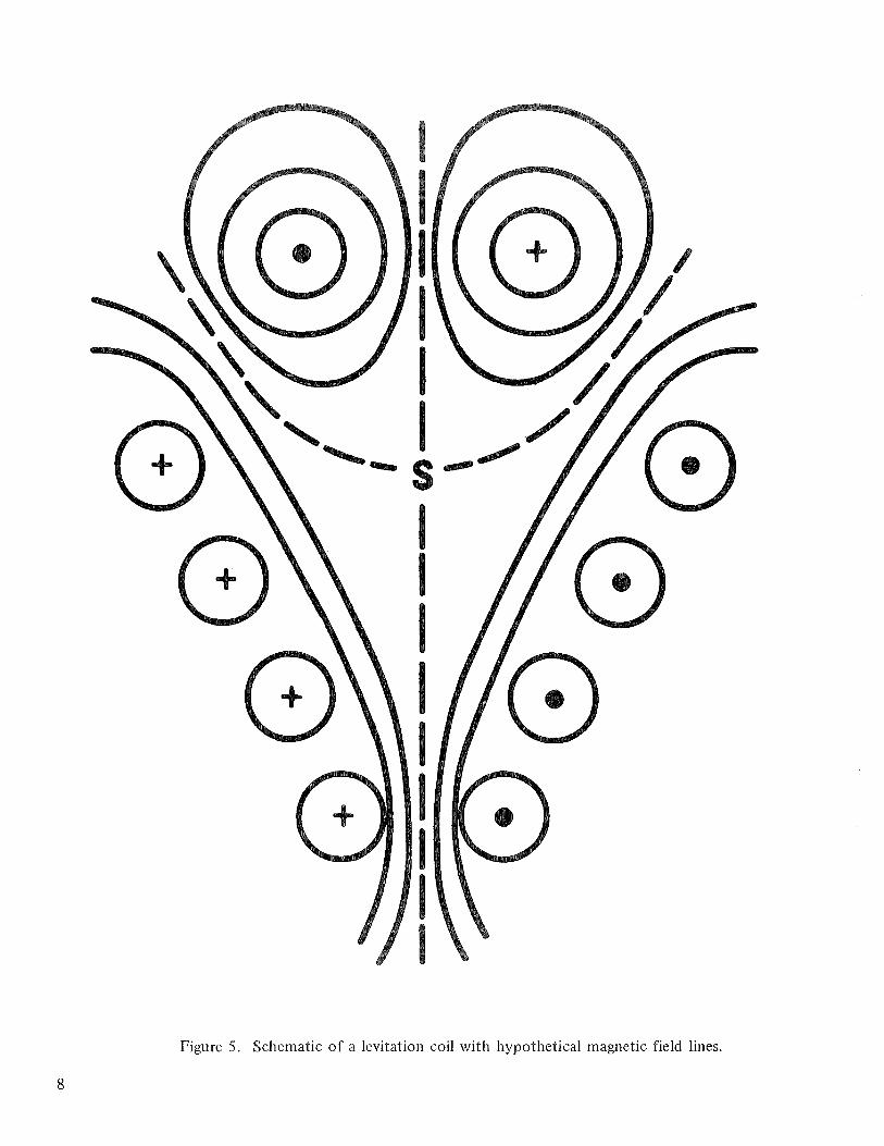
Figure 5. Schematic of a levitation coil with hypothetical magnetic field lines.

Figure 6. Electromagnetic levitation coil winding jig.

\ 2" BOLT FOR HOLDING MANDREL TOGETHER
KING COIL MANDREL
) ~ L E V ~ T A T ~ ~ N ~ H E A T I N G COIL MANDREL
STEP 2
Figure 7. Steps 1 and 2 in winding a levitation coil.

Figure 8. Steps 3 and 4 in winding a levitation coil.
1 1
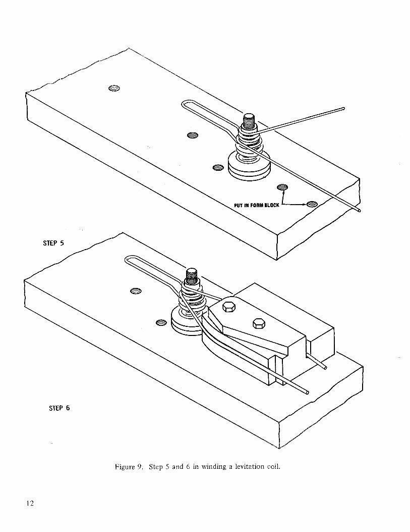
Figure 9. Step 5 and 6 in winding a levitation coil
12

Figure 10. Step 6, attaching fittings to the levitation coil leads.

Figure 11. Photograph of the lead connector jig.

REFERENCES
I . Polonis, D. H., Butters, R. G., and Parr, J. B.: Levitation Melting Titanium and Titanium Alloys. Research, Vol. 7, 1954, p. 5 10.
2. Peifer, W. A.: Levitation Melting - A Survey of the State of the Art. J. Metals, Vol. 17, 1965, pp. 487-493.
3. Downey, J. W.: Levitation Melting of Metals and Alloys. ANL-7398 Argonne National Labs., Metals, Ceramics and Materials (TID-4500) AEC Res. and Dev. Report, December 1967.
4. Slater, W. J., Barton, J. W., and Taggard, R.: Science and Industry, Vol. 7, 1960, pp. 89-96.
BIBLIOGRAPHY
Abbaschian, G. J. and Ethridge, E. C.: Containerless Electromagnetic Levitation Melting of Cu-Fe and Ag-Ni Alloys. NASA TM-825 5 3, September 1983.
Comenetz, G. and Salatka, J. W.: Ten-Gran Levitation Melted Ingots. Electrochem. Soc. J., Vol. 105, 1958, pp. 673-676.
Ethridge, E. C. and Curreri, P. A. : Containerless Electromagnetic Levitation Processing in Microgravity Conditions. Electromagnetic Moldless Casting, North Holland Publihsing Company, 1983.
Okress, E. C., Wroughton, D. M., Comentz, G., Brace, P. H., and Kelly, J. C. R.: Electromagnetic Levitation of Solid and Molten Metals. J. Appl. Phys., Vol. 23, 1952, pp. 545-552.

ELECTROMAGNETIC LEVITATION COIL FABRlGATlON TECHNIQUE FOR MSFC CONTAINERLESS PROCESSING FACIblTlES
By E. C. Ethridge, J. Theiss, P. A. Curreri, and G. J. Abbaschian
The information in this report has been reviewed for technical content. Review of any informa- tion concerning Department of Defense or nuclear energy activities or programs has been made by the MSFC Security Classification Officer. This report, in its entirety, has been determined to be unclassified.
I I
A. J. DESSgER Director, Space Science Laboratory
f? U.S. GOVERNMENT PRINTING OFFICE 1984-746-070/124