NASA TECHNICAL 53376 - ntrs.nasa.gov · NASA TECHNICAL M EMORANDUM NASATM X ... is obtained by...
22
NASA TECHNICAL MEMORANDUM NASATM X-53376 December 30, 1965 _O t_ _, N66-15358 I _ (ACGI_SS|ON NUMB[R) (THRU) ,....., ,coTg o (NA;BA CR OR TM][ OR AD NUMBIER! {¢AT_GORY} <: SELF-SEALING SHIELDSFOR MICROMETEORITE PROTECTION by ERWIN D. FUNK Propulsion and Vehicle Engineering Laboratory, GPO PRICE $ II I -- CFST! PRICE(S) I __ .... Hard Copy (HC) ,_'i_" NASA Microfiche (MF), - ff 653 July 65 GeorgeC.Marshall Space Flight Center, Huntsville, Alabama https://ntrs.nasa.gov/search.jsp?R=19660006069 2018-08-20T20:29:40+00:00Z
Transcript of NASA TECHNICAL 53376 - ntrs.nasa.gov · NASA TECHNICAL M EMORANDUM NASATM X ... is obtained by...

NASA TECHNICAL
M EMORANDUM NASATM X-53376December 30, 1965
_Ot__, N66-15358I
_ (ACGI_SS|ON NUMB[R) (THRU)
,....., ,coTgo
(NA;BA CR OR TM][ OR AD NUMBIER! {¢AT_GORY}<:
SELF-SEALINGSHIELDSFORMICROMETEORITEPROTECTIONby ERWIN D. FUNK
Propulsion and Vehicle Engineering Laboratory,
GPO PRICE $ II I --
CFST! PRICE(S) I _ _ ....
Hard Copy (HC) ,_'i_"
NASA Microfiche (MF), -
ff 653 July 65
GeorgeC. Marshall
Space Flight Center,
Huntsville, Alabama
i
https://ntrs.nasa.gov/search.jsp?R=19660006069 2018-08-20T20:29:40+00:00Z
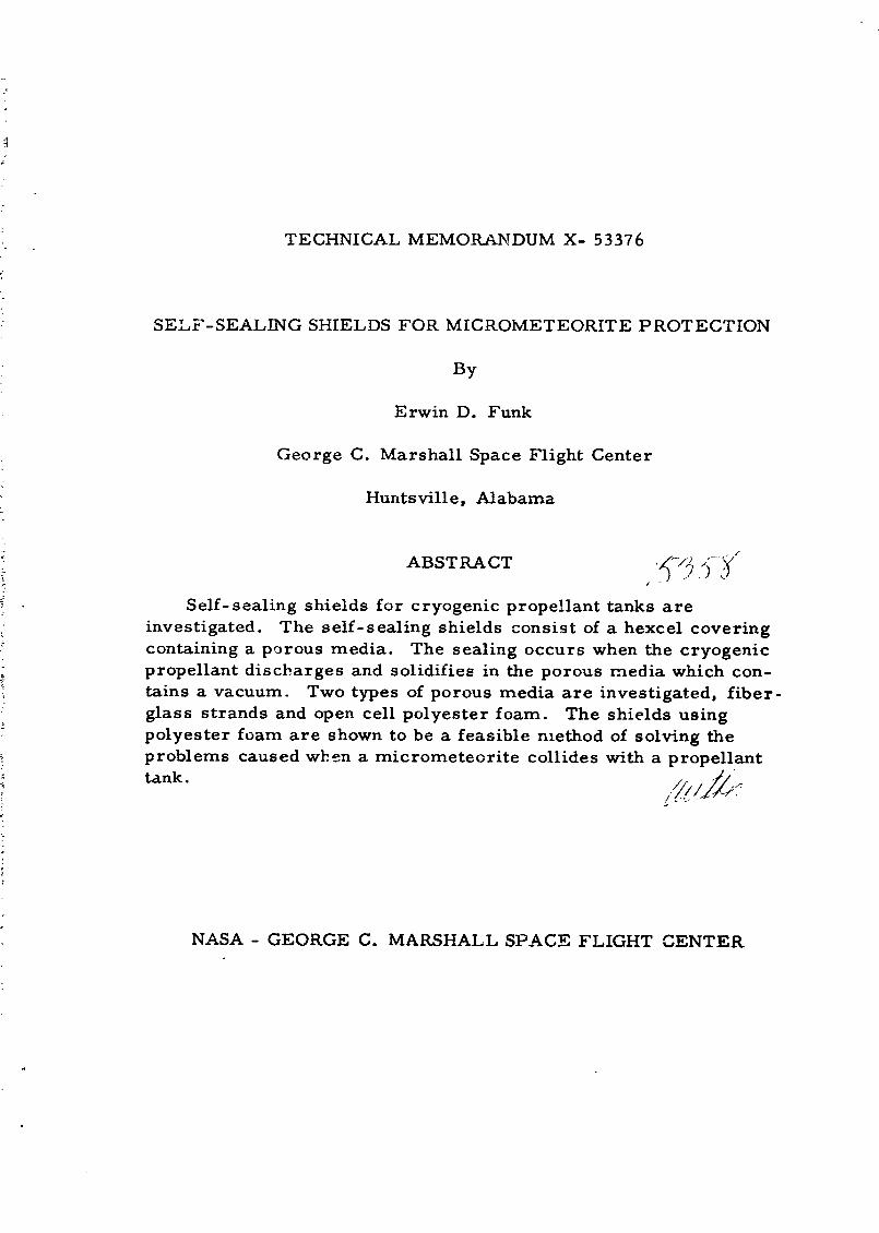
TECHNICAL MEMORANDUM X- 53376
: SELF-SEALING SHIELDS FOR MICROMETEORITE PROTECTION
By
Erwin D. Funk
George C. Marshall Space Flight Center
Huntsville, Alabama
ABSTRACT _ ; _
Self-sealing shields for cryogenic propellant tanks are
investigated. The self-sealing shields consist of a hexcel covering
containing a porous media. The sealing occurs when the cryogenic
propellant discharges and solidifies in the porous media which con-
rains a vacuum. Two types of porous media are investigated, fiber-
glass strands and open cell polyester foam. The shields using
polyester foam are shown to be a feasible method of solving the
problems caused when a micrometeorite collides with a propellant
t&nk. ///_///_/;//
NASA - GEORGE C. MARSHALL SPACE FLIGHT CENTER
1966006069-002

NASA-GEORGE C. MARSHALL SPACE FLIGHT CENTER
TECHNICAL MEMORANDUM X - 53376
SELF-SEALING SHIELDS FOR MICROMETEORITE PROTECTION
By .,._Erwin D. Funk _
3
APPLIED MECHANICAL RESEARCH BRANCH
PROPU LSION DIVISIONPROPULSION AND VEHICLE ENGINEERING LABORATORY
RESEARCH AND DEVELOPMENT OPERATIONS
,5;g_
1966006069-004

TABLE OF CONTENTS
Page
1SUMMARY ............................................
INTRODUCTION ...................................... 1
THEORY .............................................. 3
TEST PROCEDURE .................................... 5
RESULTS OF TESTING ................................ 6
ADVANTAGES OF SELF-SEALING SHIELDS ............ 6
CONCLUSIONS ........................................ 7
REFERENCES ........................................ 8
iii
1966006069-006

6
LIST OF ILLUSTRATIONS
Figure Title Page
1 Solid Plug Initiated by End Interference .......... 9
2 Test .&ppa ratus ............................... I0
3 Self-sealing Shield Specimens .................. II
4 Hazard of Meteorite Puncture ............ ...... 12
5 Non- sealing Test ............................. 13
6 Sealing Test .................................. 14
7 Range of Sealing Pressures for Polyester Foam .. 15
iv
1966006069-007
DEFINITION OF SYMBOLS
Symbol Definition Units
C Speed of sound in the target material,Propagation of sound km/s
J
i
d Diameter of meteorite, diameter of a
sphere with a mass equal to that of
the meteorite, based on Pp
P P_netration depth, distance that a
meteorite penetrates a target wh,:ncolliding perpendicular to the target
V Velocity of the micrometeorite at impact, . -£velocity of the meteorite relative to the km/s :-_tank intowhich itcollides ',:;_,
P Density , mass per unit volume g/cm $ :_
Pp Density of meteorite, mass of meteorite !_/_per unit volume, based on the material of g/cm a _ ._
the meteo, ite -_._
PT Density of target material, mass per +_,,,4
unit volume of the materi_l used for g/cm _construction of space vehicle tanks "=:
.
, /
%
ii
] 966006069-008

I
SELF-.SEALING SHIELDS FOR MICROMETEORITE PROTECTION
By Erwin D, Funk
George C. Marshall Space Flight Cen+,er l
Huntsville, Alabama
C
SUMMARY
A self-sealing shield utilizing the physical properties of a
cryogenic propellant was proven feasiole. The shield consists of i_hexcel covering lilled with a porous media applied to the 6utside ,_f,urface of a propellant tank. The sealing occurs when the cryogenicprop,_llant discharges through the rnicrometeorite puncture in the _,shield and tank wall. The ph.enomena t/,_at results is a solidification "_
of tahe cryogenic propel!ant as it encounters the vacuum of space.The solid propelIan+, is rigidly held in ",,he porou_ media and plu_s the _'hole. The most fa-'orable porous material for sealing was an opencell polyester foam. Meteorite Functures as l&rgc as 0,050 inchesin diameter were sealed with this type of shield. .,:
%
INTRODU GTION
The meteroids traveling through space pre_.e_t a potentialhazard to earth orbit and long range space vehic*e missions. A s,nallpropellan_ leak caused by a meteorite puncture of a propellant tankcould cause mission failure. Two approaches can be taken _o _limirmtethis problem of leakage: prevent meteorite penetration, or allowmeteorite penetr&tion b_ seal the puncture.
Preventing meteorite penetration become_ quite di_icult when the
meteorite masses and velocities are large; furthermore, shields thatare capable of absorbin b large meteorite impacts become very hea,_. _
This paper con1,_ers an attempt to seal the puncture agter it |a i_produced. •
1966006069-010

Present development of self-sealing mechanisms does notencompass cryogenic tar:kage. _ost sealing materials becomebrittle at vex y low temperatures, thus preventing them from re-bounding to their original position after penetration. To eliminatethe problems of sealing materials, the properties of the propellantare considered. When cryogenic liquid propellants are exposed tcpressures below their triple point, they solidify. This solidificationcan be utilized for sealing meteorite punctures. The sealing mechanismis obtained by filling the hexcels ot a hexcel insulation with a porousmedia. The sealing occurs when the propellant discharges throughthe puncture and forms a solid in the porous media.
There are many other types of self-sealing mechanisms beingstudied; these inchde multiple m_.tal sheets, porous materials thatabsorb impact, shields that produce sealing by solidification ofchemicals, and srnall spheres or discs that maneuver themselvesover the puncture. D'Anna et al. 03 have tested numerous self-sealingmechanisms at room temperatures and have had good results. Theyhave shown that air leaks can be kept Ielatively small with discs,
spheres and asbestos fibers. Mechanisms such as these might wellseal more readily when solid formations are encountered at the smallleaks that do exist.
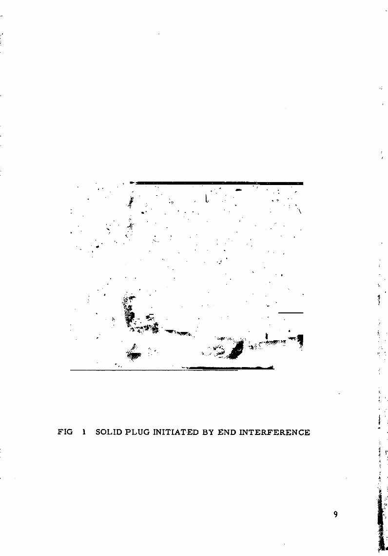
The National Bureau of Standards conducted a program on theeffects of liquid hydrogen and liquid nitrogea, discharging to a vacuum.Their findings show that leaking fluids will form a solid when exposedto the vacuum. In many cases this solid builds up and plugs the
discharging orifice. Brennan c0 demonstrated that partial pluggingcould occur when discharging LN 2 and LH 2 through 0.0l inch diameterorifices. Chelton et al.C0 showed that a tube 0.75 inches in diameter
could be plugged when nozzles as large as 0. 045 inches diameter dis-
charged LN_ and LH 2 into it. These plugs lasted as long as 45 minutesat differential pressures as high as IZ. Z psi. A photograph of thistype of plugging is shown in FIG 1, as taken from Ref. Z. Theplugging was initiated by a build up of small particles of solid nitrogenor hydrogen.
The oriD.ce sizes considered in this study are based on meteoroidflux near the earth taken from the "Satellite Environment Handbook. " [_2
1966006069-011

THEORY
Meteorite environments beyond the atmosphere of the earth have
been confirmed by numerous satellite experiments, but the size,
mass, distribution, and velocities are not well known. Johnson E43
has evaluated data on meteorite impact rates from various satellites,both American and Russian. Also included in this reference is a table
by Whipple _j for meteorite masses, radius, and flux. This table with
a few additions is shownas Table I. Whipple's radius is based on
spheres with a density of 0° 05 g/cm 3. This density assumes that the
meteorites a.'e "fluffy" particles. Dalton g_3 states that meteorite
densities may be classified broadly as (1) metallic, P = 7.8 g/cm 3,
(Z) stony, P = 3.5 g/cm _, and (3) fluffy, P = 0.443 g/cm 3. There
appears to be some doubt about a precise value for meteorite densities.
If the meteorites are stony, the radir.s would be smaller than that
shown by Whipple. The radirs based on the stony density using
Whipple's data is shown in the third column of Table I. The sixth
column shows the nu_nber of impacts per day on a three meter sphere .
derived on the assarnption of 50 per cent shielding by the earth. Yhis
data may be extrapolated to show that the number of days between
impacts of a meteorite of radius 0. 012 inches is 61.3 days. Meteorites
of diameter greater than 0.0Z0 inches, based on P= 3.5 g/cm 3, are not '
likely to strike a vehicle on a thirty day orbit.
Claarters vnd Locke 09 experimentally derived an expression for the .=:_
depth of penetration of spherical objects directed perpendicular to the /i
target. The expression is:__,
P--_-= 2.Z8 ,
)
where P is penetration depth; d is diameter of sphere; pp is density of ._
meteorite; PT is density of target material; V is velocity of sphere at i',-
impact; and C is speed of sound in target material. For aluminum _
targets impacted by meteorites with a density and velocity range of
0.5 to 7.8 g/cm 3 and 10 to 30 kin/s, repectively, a P/d range of 1.13 ':ito lB. 1 is obtained, A conservative estimate of P/d between 2 and 4 ":
for all meteorites provides a good design parameter for penetration.
This conservative estimate is somewhat larger than that given by .'.Dalton for hard aluminum. _"
3
1966006069-012

rn J , , i , , "; _ ";_ o o o o o o o o o o._ N N _ N _ N N
(/'} rq Ox _ o0 00 r_ Ox _ O0 O0 r_
,--,H :E(_
_1 _ u :>,.-. o o o o o o o o o o o','_ 'C_ I_
I:]::l H I_ (1) _ O0 _ "- I_- O_ t'- Ox ,--I O r'l il_,_ l::: (1) L_ (_ _ 0'_ (7" O _0 _1_ ,_ oo u_
_ • .....0
,el r_
[-4 (J-_. 00 r'- ,,D L_ _ 0'1 N _ O O" 00r._ _ _:_. _ (,4 _ (,,,1 ¢_1 N _ N _ _ .._
_ _ 0 _ _xl _ _ 0 0 N _D N O0 ,_c,_ O i_- _ _,4 _ e4 _II
4
1966006069-013

The mechanism used to seal tar.k punctures resulting from
meteorite collisions occurs in the following manner. Immediately
following the penetration, the liquid discharges into the affected
hexcel that contains a vacuum. As the liquid flows into the porous
media in the hexcel, the stxearr, pressure drops. When the presrure
across the porous material has dropped to the triple point, the liquid
solidifies. The porous media helps initiate, maintain, and strengthenthe solid obstruction. To ensure that the pressure drop _¢ill be
reduced tc t?:e triple point, the faces of each hexcel are perforated to
allow deeper penetration of vacuum within the hexcel. The hexcels
eliminate con_:amination of the system by localizing the solid
formation at each punctured hexcel. Since the meteorite shield is
basically an insulation, it serves a dual purpose.
TEST 1z ROCEDURE
The test apparatus is shown in FIG Z. The apparatus consisted
of a liquid nitrogen supply, an accumulator tank, a 5 _t filter, a liquid
nitrogen jacketed tube, and a vacuum source. The vacuum pressure
was always kept at less than 1 mm of mercury.
The sequence of operation follows:
All components of the test apparatus were thoroughly cooled.
The valve between the accumulator tank and specimen was opened.
The specimens were visually checked for sealing, and the highest
sealing pressure was determined. The LN 2 jacket and the vertical
position of the approach tube assured that only liquid was exhausted
into the specimen.
The hexcel used was 3/8-inch hex from point to point with a depth
of 0.5 inches. The perforations on the face were 0.06Z5 inch holes
placed at each point of the hexcel. Two types of porous media were
considered: fiberglass strands with a density of 1.4 lb/ft s, andpolyester foam wiUh a density of 1.6 lb/ft 3 and mean pore diameter of
0. 030 inches. The hexcels and porous media were applied to a 0.06Z5
inch thick aluminum plate with Adiprene L-100 adhesive. The meteorite
punctures were simulated by drilling. Liquid nitrogen was used for all
tests. FIG 3 shows the types of test specimens used.
5
1966006069-014

RESULTS OF TESTING
To determine the hazards of meteorite penetration, a hexcel was
tested that had no filling and had a mylar sheet placed one-half inchfrom the hexcel face. The results of this test are shown in FIG 4.
The solid buildup continued until it became so heavy that it droppedoff.
Tests of the shields utilizing fiberglass strands showed _at holes
up to 0.0Z0 inchrs in diameter could be sealed. The differential
pressures obtained were as high as 45 psi. Holes 0.050 inches
diameter did not seal. Inspection of the test specimens revealed that
t',-e momentum of the fluid discharging from the larger puncture
pushed aside the fiberglass strands and prevented sealing.
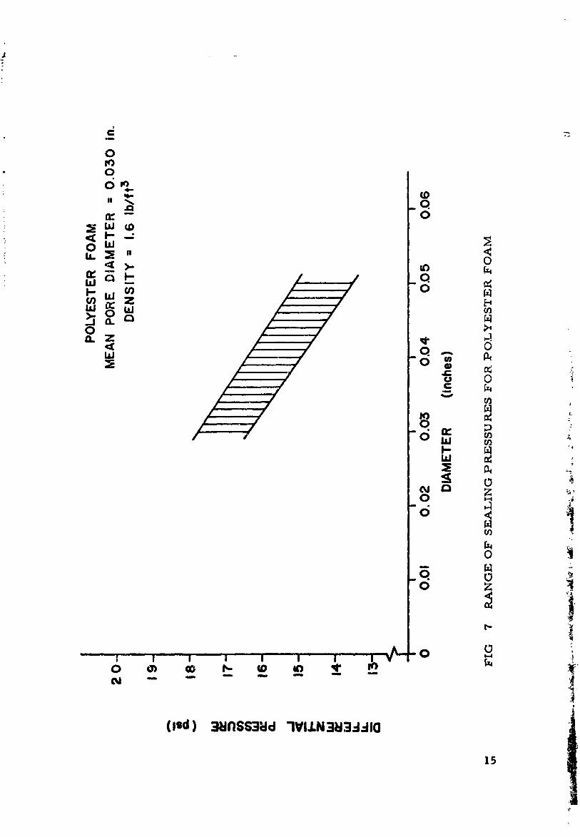
Holes from 0. 030 to 0. 050 inches in diameter were sealed during
tests of the shields using the polyester foam media. F TG 5 shows a
typical nonsealing test when the differential pressure was too high. A
fine spray of solid continually discharged from the penetration. FIG 6
shows the sealing when the differential pressure was reduced. The
interior of hexcel has turned white due to the solid plug. The range
of d_fferential pressures encountered for penetration dismembers from
0. 030 to 0.050 inches is shown in FIG 7. Penetration sizes larger
hhan 0. 050 inches were not tested because the pressurizing system
was not capable of pressures much below atmospheric. Other sealing
mechanisms were not pursued because a particle accelerating device
was not available. It was felt that further static testing would not give
results representative of dynamic tests.
ADVANTAGES OF SELF-SEALING SHIELDS
Self-sealing shields of the type tested offer many advantages.
For example, consider a ten-foot diameter spherical cryogenic tank
that requires a wall thickness of only 1/16-inch aluminum. If this
tank is designed for protection against meteorite penetration, a
thicker wall is required. Assuming a design parameter of P/d = 3
and designing for protection against meteorites up to 0. 040 inchesdiameter, the calculated wall thickness is l/8-inch this additional
thickness results in a %eight increase of X?7.3 pounds, whereas, the
weight of the sealing shield is 75.5 pounds (shield density with foam =
0. Z4 lb/ft_). Thus it can be easily seen that the shield affords a
considerable weight savings over "beefing up" the tank wall.
6
1966006069-015

If a O. 040 inch diameter meteorite penetrates the aluminum tank
containing liquid hydrogen at a pressure of 15 psia, the entire tank
of liquid will be lost through this penetration in 6.5 days. This
penetration is less disastrous if the tank is protected by a self-sealing
micrometeorite shield. Assuming that all heat radiated from the sun
over the area of the affected hexcel goes to sublimation of the solid
hydrogen, the loss of liquid hydrogen in 6.5 days is only I. 44 pounds.
The self-sealing shield has a thermal conductivity in the range from0.1 to 0.5 Btu-in/ftLhr - F. [_
Penetrations into the ullage region of the tank could cause a loss
of pressure, but cryogenic fuels such as liquid hydrogen have a
contact angle near zero, thus ensuring that liquid continually covers
the inside surface of the tank. Therefore, sealing will always occur.
CONCLUSIONS
The results of the testing show that the self-sealing shield is a
feasible method of protection for meteorite penetration, b_,t many
problems still exist. Because the porous material could shatter on
impact or be destroyed by fragmentation of the meteorite, the effects
of impact on the shield must be determined. There is a good possi-
bility that larger penetrations can be sealed by the self-sealing shields iif the pressure drop length is increased. Also, the system of floating _
discs may be used to seal larger penetrations.
if a shield of the type studied can be proven completely reliable !_,
against impact effects, it may be applied as protection for low pres-
sure fluid transfer lines, space vehicle fuel tanks, and tanks for _
storable fluids such as water, i
'iJ,:
1966006069-016

REFERENCES
1. P.J. D'Anna, R. M. Heitz, J. J. Piechocki, R. K. Jenkins,and R. W. Hunter, "Self-Sealing Structures for Control of theMeteroid Hazard to Space Vehicles, " NSL 6Z-13Z-4 (June 1963}.
2. J.A. Brennan, in Advances in Cryogenic Engineering, Vol. 9,Plenum Press, New York (1964), p. 292.
3. D.B. Chelton, B. W. Birmingham, and J. W. Dean, inAdvances in Cryogenic Engineering, Vol. 8, Plenum Press,New York(1963)jp. 311.
4. F.S. Johnson, "SatelliteEnvironment Handbook, " Stanford
University Press, Stanford (1961), p. 91.
5. F.L. Whipple, "The Meteoric Risk to Space Veh_'cles," Vistas
in Astronautics, Pergamon Press, New York (1958), p. I15.
6. C. C. Dalton, "Estimation of Tolerance Limits for Meteroid
Hazard to Space Vehicles 100-500 Kilometers above the Surfaceof the Earth, " NASA TN D-1996 {1964).
7. A. C. Charters, and G. S. Locke, "A Preliminary Investigation
of High-Speed Impact: The Penetration of Small Spheres into ThickCopper Targets, " NACA RM A58B26 (1958).
8. H. Perkins, NASA, Huntsville, Alabama, Private Comrn_mication.
8
1966006069-017
!
FIG 1 SOLID PLUG INITIATED BY END INTERFERENCE
t
1966006069-018

press _.NZDe_r
tO
,_9660

_._. • .1 . : .... _.... ....._-Y- -- ..... ,.-._ " _ ' , ._ _"
(b) ' :L:,
jf_ [
FIG 3 ' SELF-SEALING SHIELD SP_"CIMENS
] 966006069-020

FIG 4 HAT_.RD OFoMETEOR!TE PUNCT,_RE
12
1966006069-021


FIG 6 SEALING TEST
1966006069-023
0
" _ _0.
_=- oo_,,,.=_ _ o/ / o0_ -0k-
/ /// 0
/ / -0 w
// _ 0 _=
J _ .c,f -- C/]U_
-i
o .iq _
¢_ ,' | I I | I ' I I I -0 0 :lu i i ii i i ii i,_4
0 _ eD i_. _ _) _' io _ _-
(led) _l_lllSS3;:ld "IVIJ.N_I3..-IdlO
15
1966006069-024

December 30, 1965 APPROVAL TMX-53376
SELF-SEALING SHIELDS FOR MICROMETEORITE PROTECTION
By Erwin D. Funk
The information in this report has been reviewed for security
classification. Review of any information concerning Department
of Defense er Atomic Energy Commission progran_s has been made
by the MSFC Security Classification Officer. This reports in its
entirety, has b_en determined to be unclassified.
This document has also been reviewed and approved for
technical accuracy.
N. E. WELCH
Chief, Analysis Section
R. K. HEAD
Chief, Applied Mechanical Research Branch
Chief, Propulsion Division
Director, Propulsion said Vehicle Engineering Laboratory
16
1966006069-025


![. A It, NASATM X-71895€¦ · a ? to h n i.oa it, nasatm x-71895! f i x _,-i (nasa-tm-x-71895) in_e[_im analysis o_ long n76-21318 _a_ tim_ cl_]:epb_h_,vior of coluhbiuh c-ioj alloy](https://static.fdocuments.us/doc/165x107/5f06f3d27e708231d41a8e76/a-it-nasatm-x-71895-a-to-h-n-ioa-it-nasatm-x-71895-f-i-x-i-nasa-tm-x-71895.jpg)