NASA. Techical Pap,er · NASA. Techical Pap,er ... Compressor Gas-Path Seal Materials Robert C....
43
Techical Pap,er NASA. 1128 1 '. . - , I I . ~ ,I ,Friction and 'Wear of. .Several ' ' Gas-Path Seal -Materials.: i I , 1 I 1.1 Compressor I.. I . \ , . , ' 1 8 . / I ,. / ' / Robert C:' .Bifi- and Donald W. I 1 ' ( , - I 1 -, I NASA https://ntrs.nasa.gov/search.jsp?R=19780007286 2018-07-13T23:23:08+00:00Z
Transcript of NASA. Techical Pap,er · NASA. Techical Pap,er ... Compressor Gas-Path Seal Materials Robert C....
Techical Pap,er NASA. 1128 1
'.
. - , I I
. ~ , I
,Friction and 'Wear of. .Several ' '
Gas-Path Seal -Materials.: i I
, 1 I 1 . 1 Compressor
I.. I
. \
, . , ' 1 8 .
/
I ,.
/ ' / Robert C:' .Bifi- and Donald W . I 1 ' ( , - I
1
- , I
NASA
https://ntrs.nasa.gov/search.jsp?R=19780007286 2018-07-13T23:23:08+00:00Z

-~ " TECH LIBRARY KAFB, NM
-P
NASA Technical Paper 1128
Friction and Wear of Several Compressor Gas-Path Seal Materials
Robert C. Bill Propulsion Laboratory U.S. Army R&T Laboratories (AVRADCOM) and Donald W . Wisander Lewis Research Center Cleveland, Ohio
National Aeronautics and Space Administration
Scientific and Technical, lnformati,on Office
1978

FRICTION AND WEAR OF SEVERAL COMPRESSOR GAS-PATH SEAL MATERIALS
by Robert C. Bi l l * and Donald W . Wisander
Lewis Research Center
SUMMARY
Rub interaction experiments were conducted on a series of sintered and plasma- sprayed gas-path seal materials. Both blade-tip and labyrinth seal knife-edge rotor geometries were used. In all cases, the rotor was made of Ti-6A1-4V. Rotor speeds of up to 115 meters per second and radial incursion rates of 2 5 . 4 ~ 1 0 - ~ and 254x10- 6
meter per second were employed. The most rub tolerant materials based on observed rotor wear and frictional be-
havior were sintered Nichrome (-40 percent dense) and plasma-sprayed nickel - 25 percent graphite. It was also found that the radial and frictional loads encountered during rub interaction experiments with dense plasma-sprayed aluminum could be sig- nificantly reduced by providing a soft compliant backing for the aluminum.
In general, it was observed that rotor wear and high frictional energy generation rates accompanied smearing o r surface densification of the materials investigated. The onset of smearing was sensitive to rub interaction parameters and seal geometry. Two complementary models a re proposed to account for the smearing trends. One is based on thermal effects, the other on particulate escape effects. They are shown to be consistent with the elcperimental evidence at hand. Together they predict that smearing, with the onset of high frictional rub energy conditions, is favored when in- cursion rates (radial motion) are low, incursion depths are high, the seal geometry is of a knife-edge (continuous surface) character, and the seal material particle size is small.
INTRODUCTION
The efficiency of gas turbine engines is strongly dependent on clearances between stationary gas-path seal components and rotating blade tips or labyrinth seal knife edges. Very significant reductions in thrust specific fuel consumption are realizable if minimum gas-path seal clearances are maintained throughout the engine (refs.
* Propulsion Laboratory, U. S. Army R&T Laboratories (AVRADCOM).

1 and 2). Operating with minimal clearances inevitably results in rubs betwewthe rc tating and stationary components. Such rubs, occurring as they do at extremely high speeds (typically 300 to 400 m/sec), can result in destructively high temperatures, wear to the rotating components, and unpredictable behavior of the gas-path seal mate- rial comprising the static component.
From the standpoints of maintaining engine efficiency and structural integrity, it is desired that wear to the static component (gas-path seal material) occur rather than wear to the rotating component. Gas-path seal materials are designed and structured so as to preferentially undergo wear, thus minimizing wear to the rotating component in the event of a rub interaction. Generically there are three types of gas-path seal material systems employed in a gas turbine engine. First there are those that may be characterized as low density (60 to 80 percent porosity range) metallic types, often sintered. Such materials accommodate rub interactions by virtue of their friable na- ture. The discrete particles are hocked off the seal surface by the rotor. Depending on composition, these materials are used in hot or cold section locations of gas tur- bine engines.
A second class of gas-path seal materials includes more dense structures (less than 30 percent porosity) which are often plasma-sprayed and, in some cases, sin- tered, hot pressed, or even cast. Rub interactions for this class of seal materials are accommodated in a more complex manner than were those for the first type of seal material. Usually a combination of plastic deformation, material compliance (densifi- cation), and machining mechanisms is involved. Again, variations of this type of ma- terial are used in gas-path seal locations throughout the engine - elastomeric materials being employed in low pressure compressor positions, low temperature metals in higher compressor stages, and high temperature materials in the turbine.
The third class of gas-path seal materials derives its rub tolerance from the geo- metric arrangement of thin metal sheets from which the seal is fabricated. Probably the most widely used example of this type is metallic honeycomb. The honeycomb cell walls are oriented in the radial direction. Consequently, very little metal to metal contact surface area is involved when a rub interaction occurs. Honeycomb structures a re generally applied to low pressure turbine seal positions.
In this report, predictive models are proposed that describe the rub behavior of some compressor gas-path seal materials. In particular, these models describe how transitions from a relatively mild, low friction energy mode of rub interaction to a more severe mode involving much higher frictional energy occur. Experimental data a re presented and correlated with the models. The experimental data include radial and frictional force measurements, rotor temperature measurements, wear to the ro- tating components, and microscopic observations of the seal material, rotor rub sur- face, and debris resulting from the rub interaction. Experiments were performed
2

using blade- tip and labyrinth seal knife- edge rotor configurations and rotational speeds to 115 meters per second. Radial "feedrates" - henceforth to be called incursion rates - were varied; values of 25 . .4~10-~ and 254~10-~ meter per second were used.
APPARATUS
Rub evaluations were conducted on the apparatus shown in figure 1. Either a simulated labyrinth seal knife edge as shown in the inset of figure 1 or a complement of 12 simulated blade tips a s shown in the rig schematic of figure 1 were rotated at speeds to 115 meters per second. Drive power was provided by a 2.24-kilowatt induc- tion motor coupled to a continuous speed variator, thus permitting control of the rub speed.
Simulated blade-tip specimens were 3.175 millimeters thick and 12.7 millimeters wide. The knife-edge geometry was of a rectangular radial section with a 0. 508- millimeter knife-edge thickness. The rotor diameter was 19.1 centimeters for both geometries.
The gas-path seal material sample was mounted on a slideway feed mechanism so that it could be driven radially into the rotor. Radial incursion rates of 2 5 . 4 ~ 1 0 - ~ and 254x10-6 meter per second were employed.
During a rub interaction test, radial loads and frictional torque were continuously recorded, and an infrared pyrometer was used to monitor and record the blade tip o r knife edge temperature. Radial loads were sensed by means of strain gages applied to the gas-path seal material sample support. A torque transducer in the shaft system, located between the speed variator and the bearing spindle directly behind the disk, provided frictional torque data. The infrared pyrometer, located 90° past the rub con- tact as shown in figure 1, indicated the number of blade tips o r the number of discrete locations on the knife edge participating in the rub interaction per revolution as well as providing a temperature indication.
Wear debris generated during the rub interaction was collected on the fixture indi- cated in figure 1. Debris particles impinged a strip of sticky tape and thus were cap- tured for subsequent examination and evaluation. Optical microscopy, SEM, and EDAX were used to study the rub debris.
A dial gage indicator showed the relative radial motion of the feed slideway car- riage with respect to the rotating disk. Interaction depths could be controlled to within 25 micrometers of the desired depth. Usually 750-micrometer incursion depths were employed.
3
I

-.. ".- - - - - I . I I . " .
PROCEDURE
Prior .to testing, the blade tips were ground so that the tip surface was as nearly parallel as possible to the supporting root. The tip surface finish was about 0.5~10- 6
meter (20 pin. rms) after conditioning. The tips were then cleaned with ethanol, and the height of each simulated blade tip was .measured. Height variations were main- tained to within & micrometers.
For the knife-edge seal geometries, the knife edge was machined in-situ so that the maximum radial runout was & 2 . 5 4 ~ 1 0 - ~ meter. After machining the surface was honed (again, in-situ) using a Sic abrasive block and then rinsed with absolute ethanol.
Selected gas-path seal material samples were epoxy bonded to a mild steel backing which was screwed to a combination specimen support/cantilever load cell. The rotor was brought to the desired rotating speed, the selected incursion rate was set, and the rub interaction was initiated. In these tests the interaction was continued to a 750- micrometer depth.
The incursion rates employed were 2 5 . 4 ~ 1 0 - ~ and 254~10-~ me te r pe r second. Rotational speeds of 57 and 115 meters per second were selected for this study.
A posttest evaluation included blade-tip and abradable material rub surface micro- scopic examination and wear debris examination. A measure of the wear (or transfer) to the blade-tip leading edges was obtained by observing specimen focus plane height changes over the tip surface during microscopic examination. Knife-edge wear was evaluated by means of circumferential profile traces taken before and after tests; these traces indicate changes in the radial dimension due to wear of the knife edge or transfer of the seal material to the knife edge.
MATERIALS
Blade tips and labyrinth seal knife edges were fabricated from the Ti-6A1-4V alloy in the solution treated, age hardened condition (hardness was Rc 32). This particular alloy is representative of materials used for compressor blades and labyrinth seal components in current gas turbine engines.
Five gas-path seal materials were evaluated in the blade-tip and knife-edge test configurations. A sintered Nichrome material, approximately 40 percent dense (60 percent porosity), served as a standard of abradability. The sintered particles comprising this material were about 7 5 to 100 micrometers in diameter, and the ten- sile strength was about 4x10 newtons per square meter (600 psi). 6
TWO density levels (19 and 21. 5 percent) of sintered Hastelloy-X fibermetal, which is representative of compressor seal materials currently used in some engine
4

locations, were evaluated. Both of these materials were made of metal fibers typically 100 to 150 micrometers in length and 10 micrometers in diameter. The strength level of the 19 percent dense material was about 10x10 newtons per meter (1500 psi), and the tensile strength of the 21.5 percent dense material was about 12x10 newtons per square meter (1800 psi).
6 6
In addition to the sintered materials, three thermal-sprayed seal materials were evaluated. One was plasma-sprayed nickel - 25 volume percent graphite; it was sprayed to an approximate hardness of (R15 )40&10. Flame-sprayed Nichrome - 7 volume percent boron nitride with a hardness of (R15 )45&5 was also evaluated. Finally, a dense plasma-sprayed aluminum coating was assessed as a gas-path seal material. All of these sprayed materials are employed in various gas-path seal loca- tions. In addition, a 500-micrometer-thick layer of plasma-sprayed aluminum was applied to a 15-percent dense nickel - fibermetal substrate as an experimental concept to evaluate the efficacy of providing a compliant support to a dense seal material coat- ing.
Y Y
RESULTS AND DISCUSSION
Experimental observations and measurements from the rub tests a re presented first; these are followed by theoretical treatments of the various observed rub mecha- nisms. Models predicting how transitions from low frictional energy generation rate rub modes to hi& energy modes can occur are then developed. The theoretical treat- ments and modeling are shown to be consistent with experimentally observed rub phe- nomena and trends.
Rub Test Results
Blade-tip tests. - The frictional and radial load patterns, the condition of the seal material rub surface after a test, and the visible thermal effects observed during test- ing are summarized in table I for each material and test condition. Peak radial and ’
frictional load measurements are summarized in figures 2(a) and (b), respectively. Blade-tip wear and/or transfer measurements are also summarized in figure 2(a).
By way of explanation for table I, load patterns (both frictional and radial) are de- scribed as consisting of distinct events, continuous loading, or a combination of con- tinuous loading with distinct events superimposed. Continuous loading characterizes a situation in which the radial and frictional loads are fairly steady throughout a rub test. Distinct events are short-term load bursts lasting from 0.1 to 1 second. Rub surfaces are described in table I as having been smeared, cleanly abraded, or torn. A smeared
5

rub surface consists of a continuous layer of plastically deformed material as opposed to the porous, or particulate, nature of the bulk material structure. In contrast, a cleanly abraded rub surface maintains the distinctly particulate, porous nature of the bulk material. A rub surface showing cracks transversely oriented with respect to the sliding direction, propagating obliquely into the seal material, is described as showing frictional tearing.
Very low blade-tip wear occurred for the 40-percent-dense sintered Nichrome and plasma-sprayed nickel graphite; the lowest radial and frictional loads were ob- served for these materials as shown in figure 2. Significant temperature peaks could not be detected on the blade tips, and only occasional yellow sparking took place during experiments on these materials. Very little smearing or surface densification was found to have taken place on the seal material rub surfaces. The discontinuous nature of the load pattern, as noted in table I for these materials, is thought to be due to a "self-erosion" effect. When a contact event occurs, the loose seal material particles generated promote further wear to the rub surface; consequently, clearances develop between the rotor and seal material. Another event can occur only after the seal mate- rial sample has been moved far enough radially to cause contact again.
Nineteen-percent-dense sintered Hastelloy-X fibermetal was observed to transfer to the blade tips with no measurable tip wear taking place. Both radial and frictional loads were higher than those measured for the sintered Nichrome and sprayed nickel graphite. Significant temperature peaks indicating bulk blade- tip temperature rises of 200' C under the pyrometer were seen for the 115 meter per second rub conditions; temperature rises of 350' C were seen under high incursion rate ( 2 5 4 ~ 1 0 - ~ m/sec) conditions at 57 meters per second. Smearing over 20 to 40 percent of the rub surface was seen after rubbing with a 2 5 . 4 ~ 1 0 - ~ meter per second incursion rate under both tip speed conditions. Tearing of the rub surface resulted from high incursion rate test conditions; intermittent white sparking was observed during all tests.
Consistently hig%er blade-tip wear, compared to sintered Nichrome, resulted from rub interactions with 21.5-percent-dense Hastelloy-X fibermetal. Depending on the rub conditions, the radial and frictional loads were from 3 to 10 times greater than those loads measured for sintered Nichrome. Tests conducted at 115 meters per sec- ond were characterized by a semicontinuous intense white incandescense in the rub zone and by visible migratory glowing of the seal material contact surface. Tempera- ture peaks in excess of 350' C were detected under the high speed rub conditions; al- most total smearing of the seal material and heat discoloration were seen after the test. Considerably less smearing and heat discoloration of the fibermetal resulted from the 57 meter per second test.
Results from blade-tip rub interaction tests with plasma-sprayed Nichrome - boron nitride were generally similar to those obtained for the 21. %percent-dense
6

Hastelloy-X fibermetal. In addition to seal material rub surface smearing, evidence of thermal shock damage was seen in the form of occasional blistering and cracking in the rub surface.
Dense, plasma-sprayed aluminum and a 500-micrometer coating of aluminum ap- plied to a 15-percent-dense fibermetal substrate were evaluated at a 115 meter per second tip speed and 25 .4~10-~ meter per second incursion rate. Radial and frictional loads for the dense aluminum coating were quite high, the frictional force being about 10 times that of sintered Nichrome. Very heavy transfer of aluminum to the Ti-6-4 blade tips was also observed, some tips being nearly completely capped. Blade-tip temperature rises of 240 Celsius degrees were indicated under the pyrometer with three to four blade tips simultaneously interacting. Applying the aluminum coating to a compliant substrate (15-percent-dense fibermetal) reduced frictional and radial loads by slightly more than 50 percent. Tip temperatures and aluminum transfer to the blade tips were not significantly reduced, however. The thin coating remained intact and ad- herent to the substrate after the rub interaction.
A common observation for all of the blade-tip rub tests is the occurrence of maxi- mum radial and frictional loads under the high incursion rate condition (fig. 2). Also, load patterns tended to be more continuous - that is, events lasted longer - under high incursion rate conditions. Maximum blade tip wear, however, usually took place under the 115 meter per second rotational speed condition. The following sections will treat these observations in more detail.
Knife-edge seal tests. - - Frictional and radial load patterns, condition of the seal material rub surface after a test, and visible thermal effects observed during testing are summarized in table I for each material subjected to knife-edge seal interaction. Peak radial and frictional loads are summarized in figure 3 along with knife-edge wear and/or transfer measurements.
Friction and wear results for the knife-edge seal tests (see fig. 3), like those for the blade-tip tests, showed the lowest frictional and radial loads for the 40-percent- dense sintered Nichrome. Transferred seal material, 3 to 5 micrometers (0.1 to 0.2 mil) high, was found over most of the knife edge after the test. There were iso- lated wear spots about 2 micrometers (0.1 mil) deep over less than 10 percent of the surface. The rub surface was seen to be smeared with brown heat discoloration of the seal material. The load pattern was characterized as a sequence of distinct events.
Plasma-sprayed nickel - 25 percent graphite showed frictional loads about twice as high as those of sintered Nichrome and a radial load about five times that of sintered Nichrome. Seven to 10 micrometers of transfer were seen over 70 percent of the h i f e edge and 3 to 5 micrometers of wear over 20 to 30 percent. As for the sintered Nichrome, the load pattern consisted of a sequence of distinct events with rub surface smearing being observed after the test.
7
h

There was little difference between the performance of the 19- and 21.5-percent- dense Hastelloy-X fibermetals. Both materials showed frictional and radial loads 50 to 100 percent greater than those for sintered Nichrome; this was probably due to the higher strength level of the fibermetal materials. Seal material transfer to the knife edge was obsemed to be very similar to that for the 40-percent-dense sintered Nichrome with isolated spots of wear again seen.
Very high friction and comparatively heavy transfer (5 to 10 pm) over most of the knife edge (a 17-4 PH steel knife edge was used in this case) accompanied rub tests against plasma-sprayed aluminum. Providing a compliant substrate in the form of 15-percent-dense nickel fibermetal resulted in significant radial and frictional load reduction but little difference in the observed transfer of aluminum to the knife edge (again, a 17-4 PH steel knife edge). Plasma-sprayed aluminum graphite showed a considerable reduction in radial and frictional loads compared to pure aluminum, how- ever, some knife-edge wear occurred (2 to 5 pm over about 10 percent of the knife edge), and sparking was observed during the rub. The sparking is thou&t to be due to the graphite burning.
As a general observation, all of the rub surfaces resulting from interactions with the rotating knife edge were completely o r nearly completely smeared with varying de- grees of heat discoloration in evidence. Despite the smaller nominal contact area for the hife-edge geometry compared to the blade-tip geometry, radial and frictional loads for the M e - e d g e tests were not lower than those encountered in the blade-tip tests. With the exception of rub tests against aluminum graphite, temperature peaks of at least 270' C were observed at three or four active sites on the knife edge.
Survey of Rub Mechanisms and Associated Frictional Energies
Figure 4 indicates the peak frictional heat generation rates per unit nominal con- tact area for various seal materials evaluated here and in reference 3. These results were calculated from frictional force data in the following manner. The measured values of frictional force were multiplied by an assumed 322 meter per second rub speed in every case (322 m/sec was the rub speed used in ref. 3) no matter what the rub speed during the actual experiment was and then divided by the appropriate nominal contact area. Also, superimposed on the ordinate of figure 4 are ranges of frictional heat generation rate per unit contact area for three distinctly identifiable rub mecha- nisms: (1) true abradability, (2) smearing on a low density substrate, and (3) smear- ing on a dense substrate. A brief description of each mechanism follows with a more detailed treatment included in the appendixes. Figure 5 presents each of the three distinct mechanisms schematically.
8

True abradability. - When a gas-path seal material accommodates a rub interac- tion with the rotor by the mechanism of discrete particle removal with minimal plastic deformation o r plowing to the rub surface, it is considered to be truly abradable. A lower bound to the energy associated with this type of interaction is defined by the total energy required to fracture individual particles out of the rub surface at a rate consis- tent with the incursion rate of the rotor. Order-of-magnitude calculations in appen- dix A indicate that this energy is extremely low compared to measured frictional ener- gies as may be seen in figure 4. The process of particle removal is not considered to be very different for the cases of knife-edge or blade-tip rotor geometries.
Extending the individual particle fracture considerations to include effects due to the finite time required for particle removal permits estimating the frictional energy expended over and above that needed only for the fracture process. An estimate of the time required to complete the fracture process for a single particle is given in appen- dix A. Essentially, the argument amounts to a lower bound estimate of the time re- quired to propagate a crack, sowing in a plastic manner, across a typical sinter bond. This time is then used in conjunction with appropriate incursion parameters to estimate the effective contact area during the rub interaction. The frictional energy estimate for this situation (indicated on the ordinate of fig. 4) follows directly using reasonable values of material bulk strength and rub speed.
As shown by figure 4, measured frictional energies for gas-path seal materials that certainly behave as truly abradable materials (40 percent dense sintered Nichrome and the fibermetal under nonsmearing conditions) do in fact fall in the range of magni- tude predicted. The best example of such a material is afforded by the 40-percent- dense sintered Nichrome. That this material may in fact be considered truly abradable is supported by the micrographs in figure 6. The debris collected after rub interaction (figs. 6(a) and (b)) is seen to consist of discrete sintered particles. The rub surface (fig. 6(c)) shows no evidence of smearing the particulate nature of the material is still in evidence.
The truly abradable model developed in appendix A is further supported by com- paring the results summarized in figure 2(a) for' 40-percent-dense sintered Nichrome and plasma-sprayed nickel graphite with equation (2a) (from appendix A):
The term p uA&' /p'/"d)] is the predicted friction force per unit contact area. For the tests on sintered Nichrome and plasma-sprayed nickel graphite summarized in figure 2(a), friction loads are on the predicted order (0.06 to 0.3 N/cm ), they in- crease with incursion rate A, and for the sintered Nichrome at least they do not
[ 2
9

depend strongly on rub velocity V. Smearing on a low density substrate. - Under some conditions, the particles corn-
prising the rub surface of a low density porous gas-path seal material are plasticaUy smeared during the rub interaction. Thus, the rotor encounters a fully dense "paved" rub surface on a low density substrate. Conditions that tend to promote smearing are discussed in a later section.
An order of magnitude estimate of the rate of frictional energy generation when the rotor encounters a smeared surface on a low density substrate is included in ap- pendix B. Contributions due to plastic displacement of seal material in the radial di- rection and the effects of high sliding speed friction in the direction of rotation are considered. Under typically encountered incursion rates the radial plastic displace- ment contribution to energy generation is found to be negligible. Sliding friction en- ergy contributions a re governed by the effective strength of the low density material under the rub surface. Obviously, as the incursion proceeds the density of the mate- rial under the smeared surface increases. This leads to progressive hardening of the substrate and an ever increasing rate of frictional heating.
The measured frictional energy values shown in figure 4 for the case of the smeared fibermetals are in the range of magnitudes predicted. That the fibermetal showed a greater propensity to smear than did sintered Nichrome is perhaps due to the greater difficulty of removing fibermetal particles. The extent of rub surface smear- ing and subsurface densification for sintered Hastelloy fibermetal is indicated in fig- ures 7(a) to (c). Debris collected from this test is shown in figures 7(d) to (g). Pieces obviously from the smeared surface are mixed with very fine debris particles. Close examination of the fine particles reveals spherical and scroll-like shapes. An X-ray energy dispersion analysis shows that some of the fine particles are from the rotor; that is, the titanium contents were high. Also, the smeared rub surface was found to contain considerable titanium that must have transferred from the rotor.
Blade-tip specimens that had been subjected to rub interactions against the 21.5- percent-dense sintered fibermetal at 115 meters per second, resulting in smearing of the fibermetal, showed considerable effects attributable to frictional heating at the rub surface. Figure 8 shows regions of porosity beneath the blade tip rub surface thought to be due to rapid local oxidation and melting of the Ti-6Al-4V during the rub. The regions around the heat affected areas etched differently from the surrounding blade material. This is believed to be caused by a-phase stabilization that occurs upon dis- solution of quantities of oxygen in the a-p Ti-6A1-4V alloy. It should be remembered that intense white sparking and incandescense in the rub zone accompanied these tests.
Extension of the smeared rub energetics description to the case of increased sub- strate densification leads to higher predicted frictional energies because of higher ra- dial loads. The porous cermet material shown in figure 4 (evaluated in ref. 3) typifies
10

this situation with substrate densities of the order of 70 percent. Radial loads are en- visioned to be governed by a plastic indentation mechanism for knife-edge rub interac- tion geometries. The rub groove on dense aluminum (fig. 9) illustrates the plastic in- dentation mechanism controlling the normal load for a highly dense seal material.
Under some conditions the analog between blade-tip rub interactions against smeared or dense materials and the machining process appears to be quite good. For example, nearly fully dense plasma-sprayed aluminum exhibits a surface finish sug- gestive of a machining process (see fig. 9(a)). Furthermore, the debris consists mostly of very thin aluminum flakes (fig. '9(b)) as would be generated under extremely low feed rate conditions. Aluminum transfer deposits in the form of thin sheets may be seen on the blade tips in figure 9(c).
Transitions Observed in the Rub Mechanisms of Gas-Path Seal Materials
It was noted in the rub test results (figs. 2 and 3) that the frictional and normal loads, and particularly the degree of smearing observed on fibermetal materials and NiCr-BN, depended on rub interaction conditions (rub speed, incursion rate, geometry). Also, it was noted that the incidence of smearing of all materials was greater under knife-edge seal geometry tests than under blade-tip geometries. Such dependencies have been seen in other studies (ref. 8), and it is widely observed that gas-path seal performance is dependent on rub interaction parameters and seal geometries. In this section, an attempt is made to model the processes promoting the variation of rub mechanisms with gas-path seal test Conditions. Two complementary models a re de- veloped. One is based on thermal effects, the other on particulate debris escape ef- fects.
Thermal effect model. - In this model, transition from a porous to a smeared seal , material rub surface is envisioned to occur because of thermal softening of the seal
material particles due to frictional heating. Hence, an analytical description is devel- oped indicating how the temperature in the seal material mi@ vary as a function of depth beneath the rub surface under varied incursion rate conditions. Thermal effects to the gas-path seal material are modeled by considering the contact surface to be analogous to the surface of a body undergoing ablative material loss. The situation is presented schematically in figure 11. The rub interaction is idealized by assuming a uniform contact surface, steady-state conditions in a moving coordinate system having its origin at the seal rub surface, and one-dimensional heat-transfer effects. The re- sulting heat-transfer equation (ref. 4) becomes
11

The thermal conductivity of the seal material is given by KSM, d is the rate at which the contact surface moves into the seal material, and p and C are the density and specific heat of the seal material. The boundary conditions are
T = Tcr at x = O
T = T, for large x
where Tcr is a limiting sliding surface temperature and T, the bulk seal material temperature. The value of Tcr is not easily specified, but Tcr may be interpreted a s being a lowest thermodynamic heat sink temperature - for example, incipient melt- ing (ref. 5) or a distinct softening temperature resulting from metallurgical transfor- mations such as recrystallization (refs. 6 and 7).
The solution to equation (1) is
and is presented graphically in figure 11. Physically, the rapid introduction of "cold" bulk seal material to the vicinity of the rub interface under high incursion rate (high A ) conditions results in a steep temperature gradient and high heat flux necessary to main- tain the rub surface at Tcr. Conversely, high temperature effects are seen to pene- trate deeply into the seal material when A (approximately equal to the incursion rate) is low. This is consistent with the observation of increased seal material smearing tendencies observed under low incursion rate conditions. Increased smearing is pro- moted by thermal softening of the seal material. The effect of incursion rate on smearing for the case of 19-percent-dense fibermetal is summarized in figure 12. Similar trends of increased smearing under low incursion rate conditions were ob- served for the 21-percent-dense fibermetal and the 40-percent-dense sintered NiCr. This simple thermal effect model has also been proposed to account for rub surface smearing and rotor wear trends under varied incursion rate conditions for knife-edge interactions (ref. 8). Smearing, in effect rub surface densification, is undesirable as it promotes high energy rub interactions, destructively high temperatures, and in- creased blade- tip wear.
Particle escape model. - This model is particularly applicable to low density porous materials and describes a process whereby rub surface densification results from less than 100-percent escape efficiency of abradable material particles. Slightly different variations of the model a re developed for blade-tip and knife- edge interaction geometries.
12
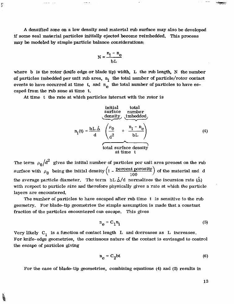
A densified zone on a low density seal material rub surface may also be developed if some seal material particles initially ejected become reimbedded. This process may be modeled by simple particle balance considerations:
where b is the rotor - m e edge or blade tip) width, L the rub length, N the number of particles imbedded per unit rub area, ni the total number of particle/rotor contact events to have occurred at time t, and ne the total number of particles to have es- caped from the rub zone at time t,
At time t the rate at which particles interact with the rotor is
initial total surface number density imbedded, -\ Y
ni(t) = - bL A (: + ni - ne) d bL
ni(t) = - bL A (: + ni - ne) d bL
total surface density' at time t
The term po/dz gives the initial number of particles per unit area present on the rub
surface with po being the initial density ( 1 - percent porosity) of the material and d
the average particle diameter. The term bL L/d normalizes the incursion rate (A) with respect to particle size and therefore physically gives a rate at which the particle layers are encountered.
100
The number of particles to have escaped after rub time t is sensitive to the rub geometry. For blade-tip geometries the simple assumption is made that a constant fraction of the particles encountered can escape.
ne = Clni
Very likely C1 is a function of contact length L For knife-edge geometries, the continuous nature the escape of particles giving
ne = Csbt
This gives
and decreases as L increases. of the contact is envisaged to control
For the case of blade-tip geometries, combining equations (4) and (5) results in
13
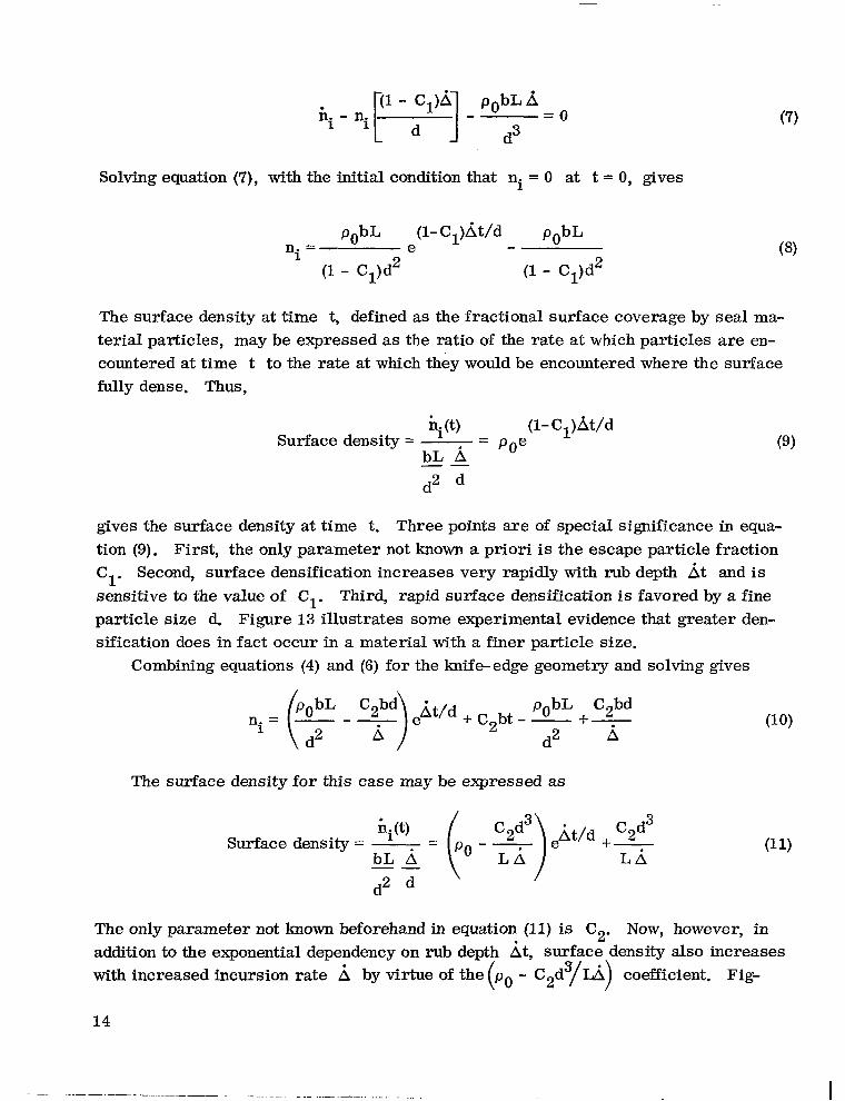
Solving equation (7), with the initial condition
pObL A - = O
d3
that ni = 0 at t = 0, gives
pObL (1- Cl)At/d pObL n2 = e - 1
(1 - C,)d2 (1 - Cl)d2
The surface density at time t, defined as the fractional surface coverage by seal ma- terial particles, may be expressed as the ratio of the rate at which particles are en- countered at time t to the rate at which they would be encountered where the surface fully dense. Thus,
+(t) (1- C1)At/d Surface density = - -
bL A - POe
"
d2
gives the surface density at time t. Three points are of special significance in equa- tion (9). First, the only parameter not known a priori is the escape particle fraction
cl' Second, surface densification increases very rapidly with rub depth At and is sensitive to the value of C1. Third, rapid surface densification is favored by a fine particle size d. Figure 13 illustrates some experimental evidence that greater den- sification does in fact occur in a material with a finer particle size.
Combining equations (4) and (6) for the lmife-edge geometry and solving gives
The surface density for this case may be expressed as
Surface density = - - ( po - - '2f) eAt/d C2d3 bL A L A
- +- LA
"
d2 \
The only parameter not known beforehand in equation (11) is C2. NOW, however, in addition to the exponential dependency on rub depth At, surface density also increases with increased incursion rate A by virtue of the (po - C z d 3 / h ) coefficient. Fig-
14

ure 14 shows the smearing tendencies (increased smearing with increased incursion rate) for low density sintered Nichrome under varied knife-edge seal interaction con- ditions.
C ONC LUSIONS
Experimental evidence and theoretical considerations for various abradable gas-
path seal materials under simulated seal rub conditions lead to the following conclu- sions:
1. The first-order frictional energy generation rates per unit contact area esti- mates are consistent with experimental results for cases of clearly identifiable seal material wear mode regimes.
2. The friction and wear performance of the gas-path seal materials studied, par- ticularly the low density materials, is seen to be sensitive to incursion rate, rotating velocity, and seal geometry through the occurrence of rub surface densification o r smearing.
3. Two models a re proposed to describe the mechanisms promoting smearing. One is based on a seal material thermal softening effect, the other on a wear particle escape mechanism. Together they predict enhanced surface densification under ex- tremes of low and high incursion rate conditions when seal material particle size is small and when under knife-edge rub geometries as opposed to blade-tip rub geome- tries. The predictions are consistent with the experimental evidence at hand.
4. Sintered 40-percent-dense Nichrome and plasma- sprayed nickel - 25 percent graphite a re the most rub tolerant of the seal materials investigated.
5. It was shown that providing a low density compliant substrate for the fully dense plasma-sprayed aluminum seal material results in significant reductions in frictional and radial loads.
Lewis Research Center, National Aeronautics and Space Administration,
Cleveland, Ohio, September 20, 1977, 505-04.
15
APPENDIX A
FRICTIONAL ENERGY ESTIMATES FOR AN ABRADABLE MATERIAL
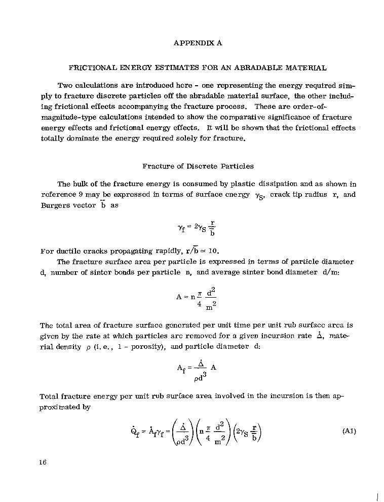
Two calculations a re introduced here - one representing the energy required sim- ply to fracture discrete particles off the abradable material surface, the other includ- ing frictional effects accompanying the fracture process. These are order-of- magnitude-type calculations intended to show the comparative significance of fracture energy effects and frictional energy effects. It will be shown that the frictional effects totally dominate the energy required solely for fracture.
Fracture of Discrete Particles
The bulk of the fracture energy is consumed by plastic dissipation and as shown in reference 9 may be expressed in terms of surface energy -ys, crack tip radius r, and Burgers vector b as
For ductile cracks propagating rapidly, r/b = 10. -
The fracture surface area per particle is expressed in terms of particle diameter d, number of sinter bonds per particle n, and average sinter bond diameter d/m:
m2
The total area of fracture surface generated per unit time per unit rub surface area is given by the rate at which particles are removed for a given incursion rate by mate- rial density p (i. e., 1 - porosity), and particle diameter d:
Total fracture energy per unit rub surface area involved in the incursion is then ap- proximated by
16

E, for example, 6 = 25.4~10-~ meter per second, d = 5 0 ~ 1 0 - ~ meter, p = 0.3, n = 4, r/b = 10, and ys N joule per square centimeter, -
Qf = 4 N-m/m - sec = ft-lb/in - sec 2 2
which is clearly quite low compared to measured levels of frictional energy.
Frictional Energy for Abradable Materials
Account must be taken of the fact that ductile crack propagation requires a finite length of time and that particles are not removed simply at the rate of geometric inter- ference. A very rough estimate of the time required for this ductile fracture process to occur may be obtained from simple dislocation considerations. Assuming a dynamic dislocation spacing of about lOOb and a mean effective dislocation velocity of about 1 meter per second (ref. lo) , the minimum number of dislocations required to propa- gate a ductile crack across a sinter bond of diameter d/m is
for d = 5 0 ~ 1 0 - ~ meter and m -= 5, as before. Moving 1 meter per second with a sepa- ration of loo%, the time required for this parade of 4x10 dislocations to pass is 4
This is essentially the time requircd to generate an abradable particle. The number of particles per unit rub surface area actually suffering an interaction at any instant is
This may be expressed in terms of the percent of the rub surface area supporting the radial at any instant:
Ar
The radial load per unit rub surface area may be esyressed as
17

and the rate of frictional energy generation per unit rub surface area is
Q - 1.4YlO N-m 1 650 ft-lb/in -sec 2 2 m -scc
Clearly the rate of frictioml heat generation per unit rub surface area dominates the fracture energy requirement.
18

APPENDIX B
SMEARING ON A LOW DENSITY SUBSTRATE
There are two contributions to heat generation associated with rub interactions when a thin, smeared layer forms on a porous substrate. First, there is plastic en- ergy dissipated in the seal material due to normal plunge (radial incursion) effects. For thin smeared layers this is significant only in the case of knife-edge interactions. This heat contribution (ref. 11) may be expressed as
where H is the smeared layer thickness, 0 the fully dense flow stress of the seal material, and W the knife-edge width. Under conditions in which the abradable matc- rial approaches full density throughout, the previous relation becomes applicable to blade-tip interactions. For the case in which A = 2 5 . 4 ~ meter per second, a -
7 Y 16x10 newtons per square meter, and H = 2 5 4 ~ 1 0 - ~ meter,
Y
Q = 80 N-m/m -sec = 0.04 ft-lb/in -sec 2 2
It is apparent that this contribution can be significant only if A is very large and/or the densified layer and contact width become very thick.
The second contribution to heat generation for the case of smearing is direct fric- tional heating. This is expressed by
where aAM is the substrate (low density material) hardness or yield strength. Under high velocity sliding conditions typical of gas-path seal rub interactions dynamic soften- ing of the smeared layer is anticipated. This will be particularly significant here as the low density substrate is a poor thermal conductor and frictional energy dissipated in the smeared layer is not efficiently removed. Under these conditions low friction is usually observed. If a friction coefficient of 0.1 is assumed and the low density mate- rial has a strength level of about 12x10 newtons per square meter at a 322 meter per second (1000 ft/sec) sliding speed,
6
Q = 3 . 9 ~ 1 0 N-m/m -sec = 1 . 8 ~ 1 0 ft-lb/in -sec 8 2 5 2
19

This quite high value of frictional heat generation is an upper bound to the smeared rub condition in the sense that 100 percent smearing and uniform contact over the entire apparent rub surface are tacitly assumed. Densification of the substrate (fig. 5(c)) would manifest itself in an increase in oAM and larger values of &.
20

APPENDIX C
SYMBOLS
Af b
b -
cP
c1
c2
d
H
KSM
L
m
N
n
ne n i
6 r
T
t
t'
V
Y S
A
I-1
fracture surface area, m
width of rub surface, m
Burgers vector, m
specific heat, J/kg-OC
particle escape fraction for blade tip geometries, dimensionless
particle escape constant for knife-edge geometries, m-sec- 1
2
particle diameter, m
smeared layer thickness, m
thermal conductivity of the seal material, J/m-sec-OC
length of rub surface, m
ratio of bond diameter to particle diameter
number of particles imbedded in rub surface per unit area, m-2
number of interparticulate bonds per particle
number of particles that escape from rub surface
number of particles interacted with during rub interaction
rate of frictional energy generation per unit contact area, J/m 2 -sec
radius of crack tip, m
temperature, K
time (independent variable), sec
time required to remove a discrete particle, sec
sliding velocity, m/sec
work of fracture, J/cm 2
surface energy, J/cm 2
incursion rate, m/sec
coefficient of friction
2 1

P particulate density (i. e., 1 - porosity), dimensionless
P mass density, kg/m - 3
strength (hardness) of seal material, N / m 2 *SM
u yield strength of ful l dense seal material, N/m 2 Y
22

-
q--
REFERENCES
1. Roelke, Richard J. : Miscellaneous Losses. Turbine Design and -4pplicatior1~ Arthur J. Glassman, ed., NASA SP-290, 1973, pp. 125-148.
2. Hauser, Cavour H. ; et al. : Compressor and Turbine Technology. Aeronautical Propulsion. NASA SP-381, 1975, pp. 229-288.
3. Shiembob, L. T. : Development of Abradable Gas Path Seals. (PWA-TM-5081, Pratt and Whitney Aircraft; NASA Contract NAS3- 18023. ) NASA CR-134689. 1974.
4. Rohsenow, Warren M. ; and Choi, Harry Y. : Heat, Mass, and Momentum Trans- fer. Prent ice Hall, Inc., 1961, p. 122.
5. Ho, Ting-Long: . Some Wear Studies on Aircraf t Brake Systems. (Rensselaer Polytechnic Inst.; NASA Grant NGR 33-018-152.) NASA CR-134989, 1975.
6. Bill, Robert C. ; and Wisander, Donald: Recrystallization as a Controlling Pro- c e s s in the Wear of Some F. C. C. Metals. Wear, vol. 41, 1977, pp. 351-363.
7. Barker, K. ; et al. : Cyclic Wear Behavior Produced by Thermal Metallurgical and Chemical Action. Presented at the ASLE 32nd Annual Meeting (Montreal, Quebec), May 9-12, 1977.
8. Bill, Robert C. ; and Shiembob, Lawrence T. : Friction and Wear of Sintered Fibermetal Abradable Seal Materials. NASA TM X-73650, 1977.
9. Averbach, B. L. ; et al., eds. : Fracture: Proceedings of an International Con- ference on the Atomic Mechanisms of Fracture. (Swampscott, Mass.), Apr. 12-16, 1959. Technology Press of MIT, 1959, p. 513.
10. Cottrell, Alan Howard: Dislocations and Plastic Flow in Crystals. Clarendon Press (London), 1953, p. 66.
11. Rowe, Geoffrey W. : Principles of Metalworking. St. Martins Press, Inc., 1965, p. 83.
.
23

TABLE I. - SUMMARY OF RUB DATA
Material Incidence of sparkiug Rub surface condition after test Characteristics of radial and frictional Incursion Tip speed,
m/sec m/sec load patterns rate,
I
Blade tip
several distinct events, 0.1- to 0. b s e c duration rhree distinct events. 0. b s e c duratlon Several distinct events, 0.1- to 0.5-sec duration
- 57 57
115
Xeanly abraded Xeanly abraded :leanly abraded
IO-Percent-dense sintered Nichrome
2 5 . 4 ~ 1 0 - ~ ! 5 4 25.4
lccasional yellow sparks kcasional yellow sparks kcasional yellow sparks
3ccasional yellow sparks 3ccasional yellow sparks Occasional yellow sparks
Intermittent bursts of white spark8 Intermittent bursts of white sparke Intermittent bursts of white spa*
Intermittent bursts of white sparks
Intermittent burets of arhite spa&
Continuous white incandescenee with red glow on rub surface
Intermittent sparking wia rad glow on rub surface
"~"""""""""~"""~~
Intense white incaudescense
No sparking seen
No sparking seen
Plasma- sprayed nickel - 25 percent graphite
57 57
115
2 5 . 4 ~ 1 0 - ~ ! 5 4 25 .4
Several distinct events. 0.1- to 0. 5-sec duration Two distinct events, 0 . 6 to 1-sec duration Several distinct events. 0.1- to 0.5-sec duratior
:leanly abraded :leanly abraded Cleanly abraded
~~
19-Percent-dense sintered Hastelloy-X fibermetal
57 57
115
- 57
57
115
- 57
57 115
~
Smeared over 20 percent of surface Frictional tearing observed Smeared over 40 percent of surface
2 5 . 4 ~ 1 0 - ~ 3.54 25 .4
2 5 . 4 ~ 1 0 - ~
2 5 4
25 .4
Continuous Continuous for 2 sec with 1 intense event Continuous for first 5 sec followed by several
distinct events, 0.5- to 1-sec duration
Continuous with occasional peaks about two times continuous load
Continuous (1- to 2-sec event)
~~ ~~
21.5- Percentdense sintered Hastelloy-X fibermetal
Smeared over 10 percent of surface
Frictional tearing observed with smearing over 10 percent of surface
Smeared over 70 percent of surface Continuous with several peaks about 50 percent h i b e r than continuous load
~~
Plasma-sprayed Nichrome - boron nitride
25. 4X10⁻⁶
254 25 .4
Continuous with two intense events, 0.1-sec
duration One intense event, 0 . 6 s e c duration One intense event, 4-sec duration
Smeared over 50 percent of surface
Smeared ridges; frictional tearing Smeared over 70 percent of surface;
frictional tearing
Pbma-sprayed aluminum 25.4X10-' Continuous Smoothly machined surface 115 - 115 Plasma-sprayed aluminum
on lbpercentdense sintered nickel fibermetal
25.4X10-' Continuous Smoothly machined surface

. -6 " -=-=.<"?. _. I
Knife edge ~"
40-Percentdense sintered
25 percent graphite i Intermittent s p a r b g Smeared Several distinct events 2 5 . 4 ~ 1 0 - ~ 115 Plasma-sprayed nickel -
Incandescense Nichrome Intermittent sparking wIth Smeared with heat discoloration Several distinct events 2 5 . 4 ~ 1 0 - ~ 115
19-Percent-dense 115 25 .4~10-~ ' Continuous ; Smeared with heat discoloration
fibermetal sintered Hastelloy-X
S p a r b g W i t h Incandescense
21. &Percent-dense 115 25. ~ x I O - ~ Several distinct events Smeared with heat discoloration Intense sparking with sintered Hastelloy-X fibermetal
Plasma-sprayed 115 2 5 . 4 ~ 1 0 - ~ Continuous Plastically displaced material No sparking
- Incandescense
aluminuma around edge of rub groove
Plasma-sprayed alumtnum edge of rub groove with recession on fibermetala
No sparking Plastically displaced material around Continuous 25. ~ x I O - ~ 115
due to substrate compliance
Plasma-sprayed aluminum
'Tested againat 17-4 PH steel Imife-edge.
graphite Yellow Sparking Smeared Several distinct events 25. ~ x I O - ~ 115

Figure 1. - Test apparatus.
26

Tip speed. Incursion rate, rnlsec mlsec
51 25.4~10-~ Ezzz x 254 115 25.4
T Indicates multiple tests
Wear to rotor, m: 10x10-6 20x10-6 20x10-6 10x10-6 20x10-6 -----" ""-" ------- 30~10-6 50~10-6 60~10-6 m 1 0 - 6 ~ ~ 1 0 - 6 70~10-6 _ _ _ _ _ _ _ _ _ _ _ _ _ _ Transfer to rotor, m: ._____. 10~10-6 ____..- ~ ..----- ~ ..----. , p r l r I - 6 MxlO-6 3x10⁻⁶, .. "" _." ~ " - """-, ~ "_"" "-,"" "-"", ~ 60x10-6, I 60x10-6 ,
40-Percentdense Plasma-sprayed 19-Percent-dense 21.5-Percent-dense Flame-sprayed Nichrome - Plasma- Plasma-sprayed sintered Nichrome nickel graphite fibermetal fibermetal boron nitride
aluminum fibermetal backing sprayed aluminum on
\ J 7
@ I Frictional hrces and wear,
Figure 2. - Frictional forces, radial forces, and wear to blade-lip edges for various gas-path seal materials in contact with Ti-bAI-4V blade tips.
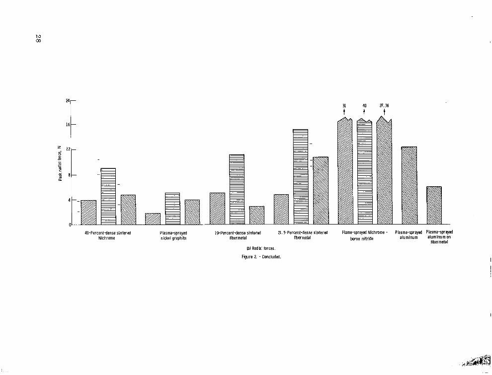
31 40 27.36 t t t
40-Percentdense sintered Plasma-sprayed 19-Percentdense sintered 21.5-Percent-dense sintered Flame-sprayed Nichrome - Plasma-sprayed Plasma-sPrsyed Nichrome nickel graphite fibermetal fibermetal boron nitride aluminum aluminum on
fibermetal (bl Radial forces.
Figure 2. - Concluded.

I2r
10-
a-
! i
Wear to rotor, pm (overstated percent of circumference): 2 110 percent)
n Radial force
Frictional force
1
11 to 14
2 110 percent) 2 110 percent) """"""""" """"""""" 2 to 5 (10 percent) 3 to 5 (20 percent) Tiansfer to rotor, pm (OverstaU
percent of circumferencek 4 (70 percent) 4 (70 to 80 percent) 4 (70 to 80 percent) 5 t o 10 180 percent) 5 to 10 180 percent) ---------------- 7 tulO(70pwcent)
40-Percentdense 19-Percentdense 21-Percentdense Plasma-sprayed Plasma-sprayed Plasma-sprayed Plasma-sprayed sintered Nichrome Hastel lv-X f ibermetal Hastel loy-X f ibermetal aluminum aluminum on alumlnum graphite nlckel graphite
""V"
fibermetal
Figure 3. - Frictional and radial loads and rotor w a r and transfer for various gas-path seal materials in contact with a Fi-MI-4V labyr inth seal kn i fe edge.

meari -
W E
c 2 V
z .-
B - aJ I= .- VI
W
W
VI e
E
4-
c W U L W
v 0
Smearir
Ref. 3
Knife-edge interactions
No smearing
al
al
0
Smearing k30 percent of rub surface
Blade-tip interactions
Figure 4. - Rub energy generation rate per unit contact area normalized to a 310 meter per second t ip speed for various gas-path seal materials. Different rub conditions result in varied degrees of smearing and subsurface densification.
30

I
i f k W
(a) Truly abradable interaction.
. \
/
'- Smeared / / /
layer 1
(b) Smearing on low density substrate.
.- Smeared , layer -
Densified layer - (c) Smearing with densification.
Figure 5. - Schematic representation of various modes of rub interaction between rotor, with peripheral speed V, driven into a porous gas path seal material at incursion rate A.
31

(a) Rub debris. (b) Typical large debris particle showing fracture sites.
(c) Rub surface revealing particulate nature of material.
Figure 6. - Sintered Nichrome debris and rub surface features resulting from interaction with Ti-6AI-4V blade tips.
32

(c) Section through rub groove norlnal to slldlng dlrectlon near erlge
Figure 7. - Rub groove surface and section features observed on smtered I-lastelloy-X flbermetal (2!.5 percent dense) after rub interartion with Ti-6AI-4V blade tips. TIP speed, 115 meters per second; lncurslon rate, 2 5 . 4 ~ 1 0 - 6 meter per second.
33

(d) Overview of debris. (e) Layered particle showing rub surface distress.
(f) Particle showing chip formation. Figure 7. - Concluded.
(g) Closeup of "chip" formation.
34

M urn U
lb) About halfway across blade tip.
Figure 8. - Section view of Ti-6AI-4V blade tip after rub interaction with 21.5-percent-dense Hastelloy-X fibermetal. Tip speed, 115 meters per second; incursion rate, 25.4~10-6 meter per second; section plane parallel to direction of sliding.
20 wr U
(a) Near blade-tip leading edge.
Sliding direction
Figure 9. - Rub groove on dense plasma-sprayed aluminum resulting from interaction with Ti-6AI-4V knife edge. Peripheral speed, 115 meters per second; incursion rate, 2 5 . 4 ~ 1 0 ' ~ meter per second; raised material produced by plastic indentation effect.
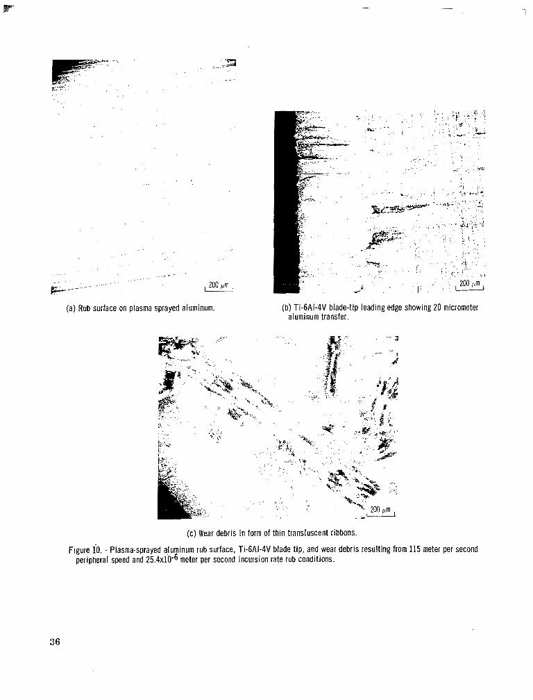
(a) Rub surface on plasma sprayed aluminum. (b) Ti-6AI-4V blade-tip leading edge showing 20 micrometer aluminum transfer.
(c) Wear debris in form of thin transluscent ribbons.
Figure 10. - Plasma-sprayed aluminum rub surface, Ti-6AI-4V b!ade tip, and wear debris resulting from 115 meter per second peripheral speed and 25.4~10-6 meter per second incursion rate rub conditions.
36

A (incursion rate)
\ I /Rotor (blade t ip
t Q seal material
Incursion rate, 4
2 I
t .- - 0-
E 2 3 1
L W n.
m
E I-
Distance into abradable material, m
Figure 11. - Schematic representation of temperature profile beneath rub surface, in abradable material.
(a) Tip speed, 7 meters per second; incursion rate, 254x10 5 meter per second.
(b) Tip speed, 57 meters per second; incursion rate, 2 5 . 4 ~ 1 0 - ~ meter per second.
(c) Tip speed, 115 meters per second; incursion rate, 2 5 . 4 ~ 1 0 ~ ~ meter per second.
Figure 12. - Relative incidence of surface smearing on 19-percent-dense fibermetal under various rub conditions against Ti-6AI-4V blade tips.
i 2
1 . '
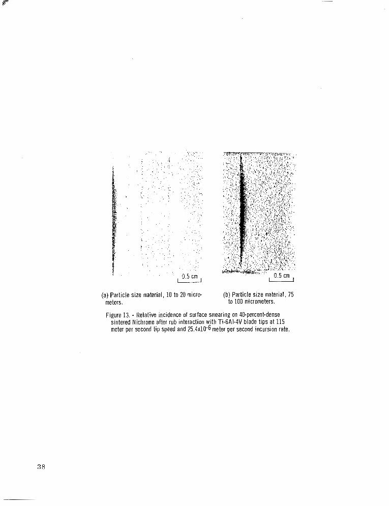
(a) Particle size material, 10 to 20 micro- (b) Particle size material, 75 meters. to 100 micrometers.
Figure 13. - Relative incidence of surface smearing on 40-percent-dense sintered Nichrome after rub interaction with Ti-6AI-4V blade tips at 115 meter per second t ip speed and 25.4~10-6 meter per second incursion rate.
38

-~ .-
"~ I 3. Recipient's Catalog No.
IP-1128 4. Title and Subtitle
" .~ .. ~ .. "~
5. Report Date
FRICTION AND WEAR OF SEVERAL COMPRESSOR GAS-PATH January lg7* " .
' - nization Code I b. rerrormmg urga 1 SEAL MATERIALS ~. ..
7. Author(s1 . -1"" . - ~~~ I 8. Performing Organization Report No. I Robert C. Bill and Donald W. Wisander
~ ~~
9. Performing Organization Name and Address NASA Lewis Research Center and Propuls ion Labora tory u. S. Army R&T Labora to r i e s (AVRADCOM) Cleveland, O'nio 44135
12. Sponsoring Agency Name and Address ~ __ " . - . . . -
National Aeronautics and Space Administration Washington, D. C. 20546
" I 505-04 10. Work Unit No.
11. Contract or Grant No.
. . 13. Type of Report and Period Covered
14. Sponsoring Agency Code
3"- ~~ ~ "I. _" 15. Supplementary Notes
16. Abstract ~ -__. ~- _ _ _ _ ~ _ _ "- - ".~ _"
Rub interaction experiments were conducted on a ser ies of sintered and plasma-sprayed com- pressor gas-path seal materials in contact with Ti-6A1-4V blade-tip and knife-edge rotors. The most rub tolerant materials investigated were sintered Nichrome (-40 percent dense) and plasma-sprayed nickel - 25 percent graphite. The effectiveness of providing a compliant sub- strate for dense seal material coatings was also demonstrated. In general, it was observed that rotor wear and high frictional energy generation rates accompanied smearing o r surface densifi- cation of the materials investigated. The onset of smearing was sensitive to rub interaction pa- rameters and seal geometry. Two complementary models are proposed to account for the smearing trends. One is based on thermal effects, the other on particulate escape effects. The: a r e shown to be consistent with the experimental evidence at hand, and together they predict that smearing, with the onset of high energy rub conditions, is favored when incursion rates (radial motion) a r e low, incursion depths a r e high, the seal geometry is of a knife-edge character, and the seal particle size is small.
1 7 . Key Words (Suggested by Authork) )
Compressor gas-path seals; Abradable seals; Friction; Wear; Frictional energy; Sintered metal; Plasma-sprayed materials
~- -- ~
18. Distribution Statement ~ ~"
Unclassified - unlimited STAR Category 26
19. Security Classif. (of this report) 20. Security Classif. (of this page) 21. No. of Pages 22. Price'
Unclassified Unclassified I A03 - ". .
'For sale by the National Technical Information Service, Springfield. Virginia 22161
NASA-Langley, 1978