NASA SPACE VEHICLE DESIGN CRITERIA [ENVIRONMENT) C
54
NASA SPACE VEHICLE DESIGN CRITERIA [ENVIRONMENT) NASA SP-8111 C ASSESSMENT AND CONTROL OF ELECTROSTATIC CHARGES MAY 1914
Transcript of NASA SPACE VEHICLE DESIGN CRITERIA [ENVIRONMENT) C

NASA SPACE VEHICLE DESIGN CRITERIA [ENVIRONMENT)
NASA SP-8111
C
ASSESSMENT AND CONTROL OF ELECTROSTATIC CHARGES
MAY 1914
FOREWORD
NASA experience has indicated a need for uniform design criteria for space vehicles. Accordingly, criteria are being developed in the following areas of technology:
Environment Structures Guidance and Control Chemical Propulsion
Individual topics are issued as separate monographs as soon as they are completed. A list of monographs published in this series can be found on the last page.
These monographs are to be regarded as guides to design and not as NASA requirements except as may be specified in formai project specifications. i t is expected, however, that the monographs will be used to develop requirements for specific projects and be cited as the applicable documents in mission studies, or in contracts for the design and development of space vehicle systems.
This monograph was prepared under the cognizance of the NASA Goddard Space Flight Center (GSFC) by Matthew Barrett of Analytic Products Inc., Bethesda, Md. Scott Mills of GSFC was the program coordinator.
Daniel Dembrow of GSFC served as the chairman of the Advisory Panel which provided guidance for the monograph’s scope and technical content. Other members of the Advisory Panel were :
Larry Brace GSFC Kenneth Carpenter Elliott DeGraff Ambionics Inc. Dominick Gignoux Columbia Research Inc. John E. Jackson GSFC Joseph Nanevicz Stanford Research Institute John Robb John Sutton GSFC
East Tennessee State University
Lightning & Transients Research Institute
Comments concerning the technical content of these monographs will be welcomed by the National Aeronautics and Space Administration, Goddard Space Flight Center, Systems Reliability Directorate, Greenbelt, Maryland 2077 1.
May 1974
i

For sale by the National Technical Information Service Springfield, Virginia 221 5 1 Price - $3.75

CONTENTS
INTRODUCTION . . . . . . . . . . . . . . . . . . . . . . . . . . . . . . . . . . . . . . . . . . . . . . . . . . . . . 1
STATE OF THE ART ................................................. 2
2.1 Design and Operational Experience . . . . . . . . . . . . . . . . . . . . . . . . . . . . . . . . . . . . 2 2.1.1 Rangerstudies .............................................. 2 2.1.2 Delta ..................................................... 3 2.1.3 Minuteman ................................................ 3 2.1.4 Titan111 . . . . . . . . . . . . . . . . . . . . . . . . . . . . . . . . . . . . . . . . . . . . . . . . . . 3 2.1.5 Apollo 12 . . . . . . . . . . . . . . . . . . . . . . . . . . . . . . . . . . . . . . . . . . . . . . . . . . 3 2.1.6 Applications Technology Satellite (ATS-5) ........................ 5
2.2 On-board Sources of Electrostatic Charges .............................. 5 2.2.1 Friction ................................................... 5 2.2.2 Rocket Exhaust Effects ....................................... 6 2.2.3 FluidFlow ................................................. 6
2.3 External Sources of Electrostatic Effects ................................ 7 2.3.1 Lightning .................................................. 7 2.3.2 Triboelectric Charging ........................................ 9 2.3.3 Atmospheric Field ........................................... 9 2.3.4 Ionosphere and Space ........................................ 11
2.3.4.1 Ionospheric Parameters ................................ 11 2.3.4.2 Effect of Ionospheric Parameters on Spacecraft Potential ...... 11 2.3.4.3 Effects of Radiation Flux .............................. 12
2.4 Electrostatic Discharge .............................................. 13 2.4.1 Corona Discharge . . . . . . . . . . . . . . . . . . . . . . . . . . . . . . . . . . . . . . . . . . . . 19
2.4.3 Surface Streamers ........................................... 19 2.4.2 ArcDischarge ............................................... 19
2.5 Hazards from Electrostatic Charges .................................... 20 2.5.1 Electro-Explosive Devices ..................................... 20
2.5.1.1 Resistive Bridgewire . . . . . . . . . . . . . . . . . . . . . . . . . . . . . . . . . . . 21 2.5.1.2 Exploding Bridgewire .................................. 21 2.5.1.3 Capacitive Discharge . . . . . . . . . . . . . . . . . . . . . . . . . . . . . . . . . . 21
2.5.2 Combustible Gases . . . . . . . . . . . . . . . . . . . . . . . . . . . . . . . . . . . . . . . . . . . 21 2.5.3 Electronics ................................................. 22 2.5.4 Communications . . . . . . . . . . . . . . . . . . . . . . . . . . . . . . . . . . . . . . . . . . . . 22 2.5.5 Persons .................................................... 22
iii

2.6 Methods for Limiting Electrostatic Charge Problems . . . . . . . . . . . . . . . . . 24 2.6.1 Prelaunch Operations . . . . . . . . . . . . . . . . . . . . . . . . . . . . . . . 24 2.6.2 On-board Sources . . . . . . . . . . . . . . . . . . . . . . . . . . . . . . . . . 24
2.6.2.1 Control of Charge Accumulation . . . . . . . . . . . . . . . . . . . . 24 2.6.2.2 Reduction of Discharge Effects . . . . . . . . . . . . . . . . . . . . 25
2.6.3 Lightning Protection . . . . . . . . . . . . . . . . . . . . . . . . . . . . . . . 25 2.6.3.1 Weather Watch . . . . . . . . . . . . . . . . . . . . . . . . . . . . . . 25 2.6.3.2 Vehicle Design . . . . . . . . . . . . . . . . . . . . . . . . . . . . . . 25
3 . CRITERIA . . . . . . . . . . . . . . . . . . . . . . . . . . . . . . . . . . . . . . . . . . . 27
3.1 Assessment of Electrostatic Effects . . . . . . . . . . . . . . . . . . . . . . . . . . . 27
3.2 Control Objectives . . . . . . . . . . . . . . . . . . . . . . . . . . . . . . . . . . . . 27 3.2.1 Fabrication and Test . . . . . . . . . . . . . . . . . . . . . . . . . . . . . . . 27 3.2.2 Flight . . . . . . . . . . . . . . . . . . . . . . . . . . . . . . . . . . . . . . . . 28
3.3 Management for Electrostatic Charge Control . . . . . . . . . . . . . . . . . . . . . 29
4 . RECOMMENDED PRACTICES . . . . . . . . . . . . . . . . . . . . . . . . . . . . . . . 29
4.1 Design . . . . . . . . . . . . . . . . . . . . . . . . . . . . . . . . . . . . . . . . . . . 29 4.1.1 Grounding Objectives . . . . . . . . . . . . . . . . . . . . . . . . . . . . . . . 29 4.1.2 Shielding by the Vehicle Shell . . . . . . . . . . . . . . . . . . . . . . . . . . 29 4.1.3 High Voltage Electronics . . . . . . . . . . . . . . . . . . . . . . . . . . . . . 30 4.1.4 Low Voltage Electronics . . . . . . . . . . . . . . . . . . . . . . . . . . . . . 30 4.1.5 Dielectrics . . . . . . . . . . . . . . . . . . . . . . . . . . . . . . . . . . . . . 31 4.1.6 Electro-Explosive Devices . . . . . . . . . . . . . . . . . . . . . . . . . . . . 31 4.1.7 Installation of Ordnance Devices . . . . . . . . . . . . . . . . . . . . . . . . 32
4.2 Testing . . . . . . . . . . . . . . . . . . . . . . . . . . . . . . . . . . . . . . . . . . . 32
4.3 Operations . . . . . . . . . . . . . . . . . . . . . . . . . . . . . . . . . . . . . . . . . 33
REFERENCES . . . . . . . . . . . . . . . . . . . . . . . . . . . . . . . . . . . . . . . . . . . 35
APPENDIX A . ELECTROSTATIC SYMBOLS AND COMMON UNITS . . . . . . . . . 39
APPENDIX B . SOME USEFUL FORMULAS FOR ELECTROSTATIC CALCULATIONS . . . . . . . . . . . . . . . . . . . . . . . . . . . . . . . . 41
APPENDIX C . CHARGING AND DISCHARGING EQUATIONS . . . . . . . . . . . . . 43
NASA SPACE VEHICLE DESIGN CRITERIA MONOGRAPHS . . . . . . . . . . . . . . 45
iv

ASSESSMENT AND CONTROL OF ELECTROSTATIC CHARGES
1. INTRODUCTION
Adverse effects of electrostatic charges on space vehicle design, development, test, and operations sometimes have been serious. Such effects include inadvertent ignition of electro- explosive devices, spurious triggering of electronics, and damage to insulating materials. The ignition by eiectrostatic charge of the final stage solid rocket motor of the Delta launch
in 1964. Electrostatic charges previously had ignited a similar motor without loss of life. In addition, failures of several vehicles after launch have been attributed to electrostatic charges.
I , vehicle for the Orbiting Solar Observatory spacecraft during test operations killed three men
Electrostatic charges in the atmosphere can have adverse effects on launch operations. NASA SP-8084, revision of June 1974, gives lightning models that should be applied to electrostatic problems. The lightning strikes on Apollo 12, shortly after liftoff, caused major disturbances to on-board electrical systems. Fortunately, most of the effects in this case were of a temporary nature and the mission was able to continue. Later, during lunar surface operations of the same mission, lunar dust was found to cover many of the experi- ment packages and space suits, thus causing them to overheat. The attraction of the dust particles to the thermal control surfaces may be partially attributable to electrostatic charges. Electrostatic charges have been of concern in the design of scientific satellites because of the need to account for electrostatic effects on sensitive instruments in the ionosphere and space.
Hazards to space vehicles can arise from electrostatic charges that are generated on board, externally, or by interaction between the space vehicle and its environment. Damage gener- ally occurs during the sudden breakdown of matter in the field between accumulated charges of opposite polarities. This results in a current surge which is characterized by a very fast rise time and a high intensity for a very short period. Techniques for minimizing the foregoing hazards are available, but hazardous situations are not always recognized.
The problem of electrostatic charges sometimes is confused with problems of electro- magnetic interference (EMI). A program to control EM1 is not closely related to require- ments for preventing damaging electrostatic charges. (EM1 is treated in a separate design criteria monograph, NASA SP-8092.)
1
To be effective, a program to minimize the hazards of electrostatic charges must be insti- tuted early in the design phase and must consider all aspects of the design, test, launch, and operations of the launch vehicle, spacecraft, and experiments. This monograph is intended (1) to alert the designers of space vehicles and experiments to problems associated with electrostatic charges, (2) to provide methods for assessing these problems, and (3) to show means for handling them. For more detailed treatment of particular aspects, the reader is directed to the references cited.
Section 2 of this monograph describes experience of NASA and DOD with electrostatic problems, generation mechanisms, types of electrostatic hazards, and current methods for handling electrostatic problems. Section 3 gives guidelines for judging the possible effects of electrostatic charges on a space vehicle mission and methods for establishing requisite con- trol of electrostatic charging by design, development, and testing. Section 4 gives recom- mended practices and techniques for carrying out the objectives of section 3. Pertinent mathematical formulas and definitions are presented in the appendices.
Also available in this series are monographs that describe the natural environments of the Earth and other planets. Other design criteria monographs treat space vehicle technology in the areas of vehicle structure, guidance and control, and chemical propulsion. All mono- graphs are listed at the end of this monograph.
2. STATE OF THE ART
2.1 Design and Operational Experience
To obtain a practical understanding of the nature and extent of electrostatic hazards in space flights, it is worthwhile to review some of the documented incidents of failure or marunction that resulted from electrostatic charges.* The incidents show that unwanted or dangerous electrostatic effects may be generated by discharging aboard the space vehicle, by interaction with external objects on the ground, or by interaction with the atmosphere during flight.
2.1.1 Ranger Studies
During preorbital flight, some systems of a spacecraft are turned off or are in a standby mode. Analysis of flights indicates that during this time electrostatic discharging may occur. This could actuate a circuit prematurely; for example, a high voltage power supply could be turned on at an altitude at which reduced atmospheric pressure may permit arcing through insulation. This could lead to the destruction of the power supply (ref. 2).
*However, electrostatic charging can be used constructively; for example, the self-repulsion of a charged body could deploy and support in space an antenna (ref. 1).
2

2.1.2 Delta
During testing, the X-248 rocket motor of the Delta launch vehicle was accidently ignited in November 1963. Again in 1964 the X-248 motor ignited accidentally during ground handling with fatal results. Investigation indicated that electrostatic charging had occurred when the nonmetallic rocket casing had been rubbed in handling of a polyethylene cover. Sudden movement of the polyethylene resulted in a rapid increase of the voltage associated with this charge. The voltage was enough to fire an igniter squib (ref. 3).
2.1.3 Minuteman
A buildup of electrostatic charge apparently caused two failures of Minuteman flight test missiles (ref. 4). The reentry vehicles of the two missiles were not electrically bonded to the rest of the vehicles. The apparent result was that the reentry vehicle became charged suf- ficiently by the engine or another mechanism to cause a spark discharge that disabled the missile guidance and control system.
2.1.4 Titan 111
Titan I11 vehicles C-10 and C-14 had guidance computer anomalies for a short interval a few seconds after launch, but computer performance recovered to permit successful missions. Investigation of these anomalies showed that the guidance computer was very sensitive to electrostatic discharging. Discharges across a 0.8 mm air gap that was eight feet away from the computer would sometimes cause an anomaly similar to that observed in the flights. Two possible causes were identified. As the more likely cause, the computer anomaly was attributed to electrostatic charging from the circulation of cooling fluid for the computer through teflon-lined hose with a braided steel jacket. Some sections of this hose were not grounded; bench tests revealed that flow of the coolant in these sections could build up a sufficient charge to discharge at the altitude where the anomalies occurred. Another possible cause of the anomalies was triboelectric* charging of the ablative coating of the payload fairing by ice particles in passage through the lower atmosphere with consequent sparking (ref. 4).
2.1.5 Apollo 12
Within seconds after launch of the Apollo 12 vehicle, it was struck at least twice by lightning. The lightning strokes caused interruption of communications, instrument distur- bances, illumination of many warning lights, disconnection of fuel cells, tumbling by the inertial guidance system, and disturbances to the timing system. Nine measuring instruments were permanently damaged (ref. 5).
The launch was made during the passage of a cold front and low clouds were present, but no lightning had been observed prior to liftoff. The lightning discharges appear to have been induced by the presence of the Apollo 12 vehicle below a cloud that carried electrostatic
*Triboelectric (or frictional) charging is discussed in section 2.2.1.
3

charges. The conducting surfaces of the vehicle and the conducting gas plasma of its exhaust plume apparently formed a long cylinder which shortened the resistive distance for an electric discharge from the cloud to ground. Figure 1 illustrates the effect. When the field
/ /
ELECTRIC FIELD / EQUIPOTENTIAL LINES \
\
--
\ \
\ \ \ \
-c---
0’ /
/ /
/ / I
Figure 1.-Distortion of lines of equal electric potential in the Earth‘s field, caused by Apollo 12 rocket that led to breakdown conditions above and below rocket (ref. 5 ) .
4

strength reached the dielectric threshold of the atmosphere, breakdown resulted between cloud and flight vehicle and the lightning stroke resulted.
The discharge probably propagated both up and down from the vehicle. The path of current flow along the vehicle would be on its outer surface, but transient currents were induced on internal circuitry.
2.1.6 Applications Technology Satellite (ATS-5)
On August 12, 1969, the ATS-5 was launched into synchronous orbit at 105’ West longi- tude. Within weeks, telemetered data indicated that the spacecraft had charged up to a potential of - 10kV. In addition, it was concluded that observed long-term degradation of the aluminized Mylar thennal blankets and difficulties with telemetry could be attributed to sparking from differential charging of spacecraft surfaces.
The most probable cause of the high potential charging is bombardment of the spacecraft by high energy charged particles of solar wind substorms. The spacecraft has potentials in the order of several hundred volts negative in sunlight. In eclipse, the potential can reach - 1 OkV, apparently because of the flux arid energy of the proton and electron plasma. The negative potential presumably is reduced by the opposing action of the photoelectric effect when ATSd is in sunlight (ref. 6).
2.2 On-board Sources of Electrostatic Charges
Large, stable electrostatic charges (positive and negative) can be generated on spacecraft and launch vehicles by several processes for which appendix C gives the fundamental equations. The principal on-board mechanisms are triboelectrification or friction, rocket exhaust effects, and fluid flow.
2.2.1 Friction
Triboelectrification (charge accumulation that results from rubbing or interrupted contact between dissimilar materials) is a major cause of electrostatic charging. In general, dissimilar materials acquire opposite charges when they are placed in contact or are rubbed together; the material with the larger dielectric constant usually bears the positive charge. Charge separation can even occur between two identical pieces of material provided they are rubbed in an assymetric way so that friction occurs at one spot on one but over a wide surface on the other. Experimenters have generated “triboelectric series” to indicate which material becomes positively charged and which becomes negatively charged. Unfortunately, one can not predict accurately the polarity and magnitude of the charges because they depend on the nature of the surface and the method of rubbing or contact. One empirical series follows:
+platinum, paper, cellulose acetate, cellulose triacetate, polyethylene, aluminum, polystyrene, copper, rubber -
5
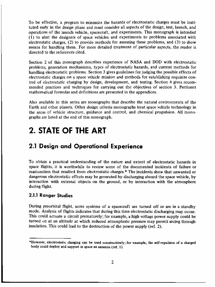
A material in this series receives electrons and acquires a negative charge when it is rubbed with a material that precedes it on the list; conversely, a material usually loses electrons and acquires a positive charge when it is rubbed with a material that follows it. Not many of the available electrons cross between contacting materials. About 10l2 electrons per cm2 is a high value but represents only about one-millionth of a coulomb; normal observations are lower by a factor of a hundred or so (ref. 7).
A number of triboelectric hazards were found and corrected during the Apollo program. Rubbing of spacesuits and coming into contact with glass-fibered cloth, such as contained in a plastic couch cover, results in a charge buildup. The charge is generally small, and any resulting spark is not an ignition hazard under current design conditions (ref. 8). However, small sparks of static electricity, that were noted to result from rubbing the astronaut’s suit during normal operations have been evaluated for the possible hazard of their igniting a combustible gaseous mixture in the cabin or a combustible such as log book paper. To avoid such hazards, charges on spacesuits were grounded by using a biomedical sensor wire. Similarly, a grounded metal screen was fitted under the couch cover to prevent charge buildup. Storage canisters placed in teflon receptacles were observed to spark when pulled from the teflon. Grounding the canister during insertion and withdrawal eliminated this problem.
The teflon fabric belt and pulley designed for hoisting Moon samples into the Lunar Excur- sion Module were also sources of electrostatic charging. Rubbing during the hoisting opera- tion was found to charge the belt sufficiently for it to attract dust such as hematite or basalt. To prevent charge accumulation, the belt was sewn in a zigzag pattern with metal thread that provided a path for charge drainage. Consequently, dust pickup was eliminated.
2.2.2 Rocket Exhaust Effects
Electrostatic charging by rocket engines has received considerable study (refs. 9, 10, 1 1, and 12). The complex environment within the rocket chamber (where gases and plasma react at high temperatures) and the effects of the exhaust on vehicle charging are still not com- pletely understood. Charging of the rocket chamber by electrons has been proposed as well as several other mechanisms (refs. 13, 14, and 15). These include thermionic emission from the heated walls of the combustion chamber and nozzle, triboelectric charging by solid particles in the exhaust, photoelectric emission, and fuel atomization.
2.2.3 Fluid Flow
The motion of liquid rocket piopellants through pipes has been recognized as a contribution to the charging of liquid fuel rockets. Any spacecraft system involving non-conductive fluid flow can develop electrostatic effects.
The splashing of liquids leads to “waterfall” effect in droplet-laden air. The result is charging of the droplets and opposite charging of the atmosphere. Charge magnitudes of about coulombs per gram of water have been observed in waterfalls (ref. 16). Both the waterfall ef- fect and liquid flow through pipes are of concern in filling vehicle tanks with liquid propellant.
6

To prevent charge accumulation, gr;ounding straps are used when fueling ships, aircraft, and launch vehicles. For aircraft fueling, a chemical agent for static dissipation has been intro- duced to eliminate charging hazards from liquid flow (ref. 17). Another technique for dissipating charges is by use of radioactive material when automatic equipment precludes possibility of exposure of persons.
2.3 External Sources of Electrostatic Effects
The space vehicle encounters a number of external sources of electrostatic effects during its operational life. From launch until the space vehicle has passed into the stratosphere, it is subject to atmospheric conditions. These include ice crystals in high clouds, the vertical electric field gradient, and large concentrations of electric charge in rain clouds.
The dielectric strength of the atmosphere is at a minimum at the reduced pressures of altitudes around 30 km. This increases the possibility that electrostatic charging will cause electrical breakdown of the medium between space vehicle components (sec. 2.4).
In the ionosphere, the encounters of ions and electrons with the space vehicle have electro- static effects that are of concern in design of experiments. Above the ionosphere, the external source of electrostatic effects is the radiation flux consisting of sunlight and ener- getic charged particles.
2.3.1 Lightning
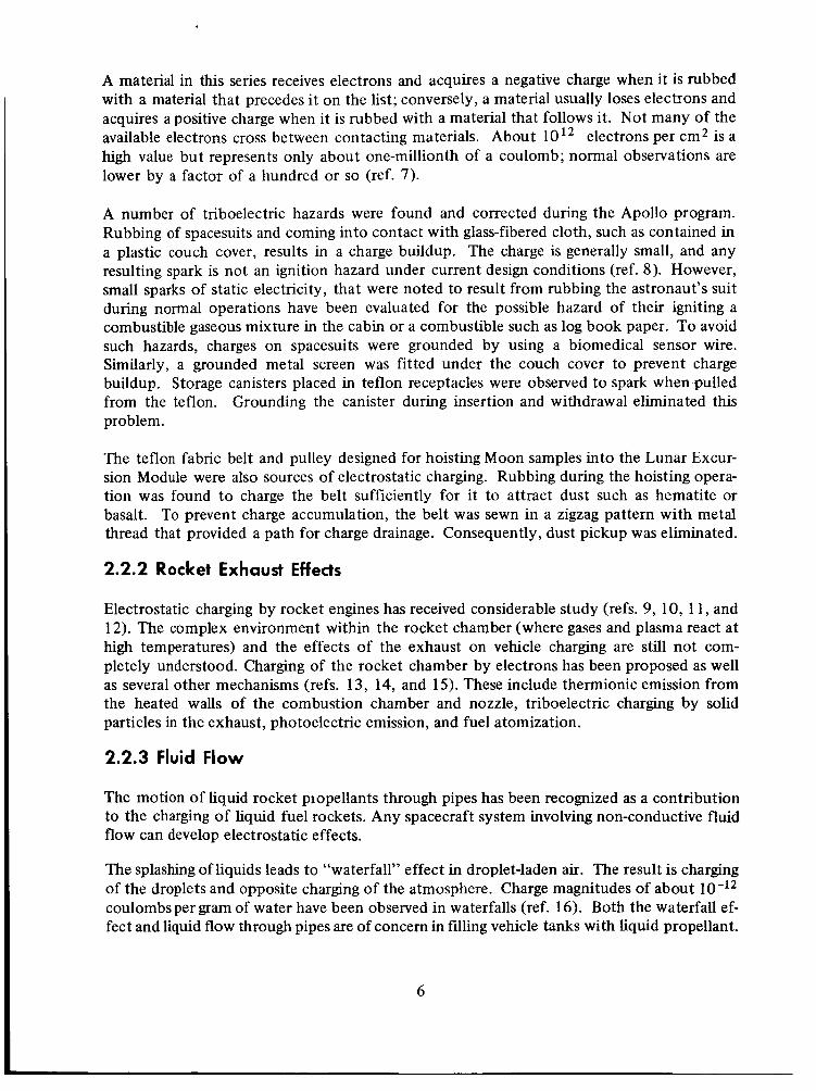
Typical thunderstorm cells are created by the heating and humidification of an air mass near the Earth. When this air mass rises to an altitude where the temperature is well below freezing, ice crystals grow and form an ice cloud. The rising, falling, and wind-created turbulence of the ice crystals in the presence of water droplets and snowflakes lead to electric charge separations in the thunderstorm cell. Charge densities of the order of 40 C/km3 are to be expected in a typical cell (ref. 18). A schematic drawing of the mature stage of development of the cell is given in figure 2. NASA SP-8084 presents the currently accepted parameters for electric fields during fair weather, cloudiness, and thunderstorms. This reference gives characteristics of lightning discharges, frequency of thunderstorm days at NASA launch sites, and means for estimating the effect of structural height on probabil- ity of lightning strikes. Recent studies are developing new data in this subject area, such as presented in figure 3.
Even though weather conditions are not sufficient to generate a lightning stroke from a thunderstorm cloud to the ground, a stroke can be triggered by the launch of a space vehicle. Because the vehicle is an excellent electrical conductor that presents an equipotential sur- face, it distorts the field between the charged cloud and the ground, as shown by figure 1. Sufficient localization of the field can result in breakdown such as occurred in the Apollo 12 launch. In this case, strokes were triggered at an altitude of 1.9 km (6400 ft) when the potential gradient measured near the surface was about 3500 V/m.
7
- t U 0
12.4 40
35
9.3 ---- 30
w 0 3
25 k 5 a
6.2 ----- 20
15
10
1.6 ---- 5
0
MOVEMENT OF CELL
T ICE CRYSTALS + + + + + I
+ + + + + + - - - - + + + + + + + ARROWS REPRESENT WINO DIRECTION A N D VELOCITY
-NEGATIYE.CHARGES +POSTIVE CHARGES
-5 1
-38
-26
-16
-8
0
8
17
28
0
W
3 + W
e a
2 E n
l-
Figure 2.-The approximate charge distribution in a mature thunderstorm cell and the ground beneath it. (after ref. 18).
8

1
14 12 10 8 6 4 2
4 8 12 16 20 24 28 32 34 38
ALTITUDE (thousands of ft)
Figure 3.-Distribution in altitude of a measured series of lightning strokes to aircraft (ref. 25).
Additional information about lightning phenomena is given in references 19, 20, 21, 22, 23, and 24.
2.3.2 Triboelectric Charging
Triboelectric charging, commonly called frictional charging, was discussed in connection with on-board sources of charging in section 2.2.1. The transfer of electrons between exter- nal sources and the flight vehicle is the same phenomenon. Such transfer can be expected whenever a flight vehicle passes through the atmosphere and is enhanced by passage through a dust cloud or a cloud of ice crystals.
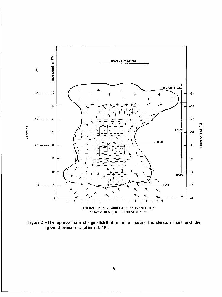
The rate at which a vehicle acquires a charge and the polarity of the charge depend on the dielectric constants of the vehicle surface and the charging particles and on the frequency and velocity of encounters. Measurements on commercial jet transports flying through clouds of ice crystals have indicated rates of accumulation of charge as high as 5x 1 0-3 C/s or 5 mA. One aircraft reached a potential of 500 kV (ref. 26). Higher voltages are prevented when loss of charge by corona discharge equals the rate of collection by aircraft motion. Measurements of potential on a sounding rocket flight are shown in figure 4.
2.3.3 Atmospheric Field
A natural potential gradient exists in the atmosphere which varies with ground location and weather conditions. From a fair-weather value of 100 to 300 V/m at the surface, the potential gradient decreases non-linearly with altitude until it reaches about 4 V/m at 10 to 12 km.*
*Anon.; Surface Atmospheric Extremes (Launch and Transportation Areas), NASA SP-8084, revised, June 1974.
9
h
2 -I
z W I- 2 W I- O n W -I
0 I W >
5
PAY LOAD
10
0
-10
-20
-30
I 77.1 m
ALTITUDE (km)
Figure 4.-Measured electric potential of a Nike-Cajun sounding rocket flight into the stratosphere (ref. 27).
This potential gradient of the atmosphere along a 100 m high vehicle ready for launch could result in a potential difference of over 10,000 V between the ground and the region near the top of the vehicle if it is not grounded. Grounding the vehicle eliminates this potential by allowing free charge to flow from the Earth. The charge (equal to the product of the voltage and the capacitance of the vehicle) can be estimated for typical vehicles 30 to 100 m high with capacitances around 1000 pF to be in the order of to 10-5C (ref. 4).
At liftoff, the plume of ionized gases between vehicle and launch pad acts as a conductor that momentarily retains the electrical connection with the ground and hence increases induction charging of the vehicle by the atmosphere. The charge may be enhanced during bad weather conditions because the potential gradient of the atmosphere would increase.
10
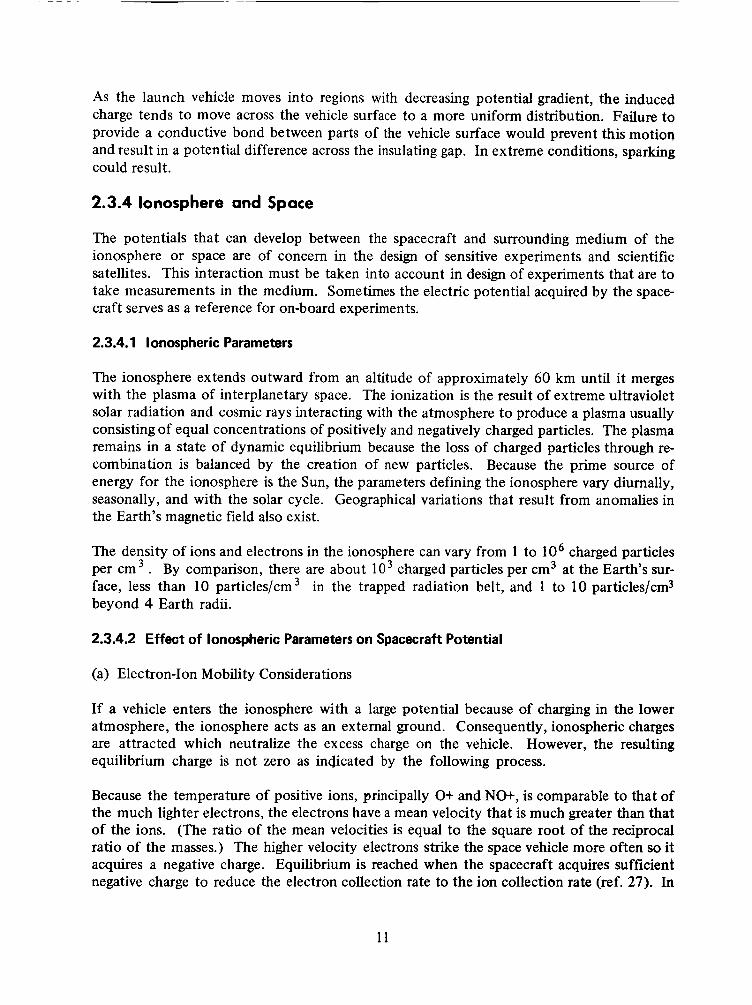
As the launch vehicle moves into regions with decreasing potential gradient, the induced charge tends to move across the vehicle surface to a more uniform distribution. Failure to provide a conductive bond between parts of the vehicle surface would prevent this motion and result in a potential difference across the insulating gap. In extreme conditions, sparking could result.
2.3.4 Ionosphere and Space
The potentials that can develop between the spacecraft and surrounding medium of the ionosphere or space are of concern in the design of sensitive experiments and scientific satellites. This interaction must be taken into account in design of experiments that are to take measurements in the medium. Sometimes the electric potential acquired by the space- craft serves as a reference for on-board experiments.
2.3.4.1 Ionospheric Parameters
The ionosphere extends outward from an altitude of approximately 60 km until it merges with the plasma of interplanetary space. The ionization is the result of extreme ultraviolet solar radiation and cosmic rays interacting with the atmosphere to produce a plasma usually consisting of equal concentrations of positively and negatively charged particles. The plasma remains in a state of dynamic equilibrium because the loss of charged particles through re- combination is balanced by the creation of new particles. Because the prime source of energy for the ionosphere is the Sun, the parameters defining the ionosphere vary diurnally, seasonally, and with the solar cycle. Geographical variations that result from anomalies in the Earth’s magnetic field also exist.
The density of ions and electrons in the ionosphere can vary from 1 to lo6 charged particles per cm3 . By comparison, there are about l o 3 charged particles per cm3 at the Earth’s sur- face, less than 10 particles/cm3 in the trapped radiation belt, and 1 to 10 particleslcm3 beyond 4 Earth radii.
2.3.4.2 Effect of Ionospheric Parameters on Spacecraft Potential
(a) Electron-Ion Mobility Considerations
If a vehicle enters the ionosphere with a large potential because of charging in the lower atmosphere, the ionosphere acts as an external ground. Consequently, ionospheric charges are attracted which neutralize the excess charge on the vehicle. However, the resulting equilibrium charge is not zero as indicated by the following process.
Because the temperature of positive ions, principally O+ and NO+, is comparable to that of the much lighter electrons, the electrons have a mean velocity that is much greater than that of the ions. (The ratio of the mean velocities is equal to the square root of the reciprocal ratio of the masses.) The higher velocity electrons strike the space vehicle more often so it acquires a negative charge. Equilibrium is reached when the spacecraft acquires sufficient negative charge to reduce the electron collection rate to the ion collection rate (ref. 27). In
11

the absence of other charging mechanisms, the spacecraft equilibrium might have a negative potential of 0.9V at a temperature Df 2000°K according to Langmuir probe theory (ref. 28). Several measurements have agreed in magnitude with this result (ref. 9).
(b) v X Effect*
When a conductor moves through a magnetic field, an electric field E is developed across the conductor according to the relationship,
where v is the velocity vector of the conductor, B is the magnetic field vector, and X indicates a cross product. In the case of the spacecraft interaction with the environment, the magnetic field is that of the Earth, and the conductor is the metallic skin or appendages of the spacecraft. If the spacecraft has long booms or antennas, a potential of several tens of volts can be developed. (This potential is E E, Le., the dot product between E and conductor length E). In the absence of B, the spacecraft is an equipotential surface and the mobility considerations discussed in section 2.3.4.2(a) cause the potential to be slightly negative with respect to the ambient plasma.
The v X B effect leads to non-uniform values for the potential between the spacecraft and the ambient medium. The potential difference between any point on the spacecraft and the adjacent undisturbed plasma at a given instant can have values ranging from near zero to several tens of volts negative. (Electron mobility in the ionospheric plasma prevents any spacecraft point from acquiring a large positive potential).
The plasma sheath that results from the V X effect is non-uniform and its thickness at any point varies as the spacecraft spins and thus changes orientation with respect to the mag- netic field. This variable sheath can have unfortunate effects on experiments mounted on the spacecraft such as Langmuir probes measuring ambient densities and temperature.
One way of ameliorating this condition is to couple the antennas capacitively, at the same time insulating the roots of the antennas for a distance approximately equal to the radius of the plasma sheath.**
2.3.4.3 Effects of Radiation Flux
The spacecraft is also exposed to the radiation flux consisting of energetic charged particles and sunlight. The greatest intensity is found in the Earth’s trapped radiation belt. Energetic charged particles, principally electrons and protons, can penetrate the spacecraft surface and
*M. A. Kasha treats the v X Gordon and Breach, 1969.
no. 6, June 1969, p. 871 and fig. 3.
effect in detail in “‘I‘he Ionosphere and Its Interaction with Satellites,”
**Florida, C. D., “Development of a Series of Ionospheric Satellites,” proceedings of the IEEE, vol. 57,
12

impart electric charges to the spacecraft. Because of their lower mass, electrons in thermal equilibrium in a proton-electron plasma strike a spacecraft more often than protons, and a net negative charge is developed. The high energies of the particles lead to secondary emis- sion of electrons that superimpose a positive charging on the primary particle charging effect. Sunlight adds positive charge to the spacecraft by the photoelectric effect. As a result of these processes, the surface of the spacecraft acquires a charge and the spacecraft acquires a potential. * Measurements of spacecraft potential on Sputnik 3 showed a negative potential that ranged from -2 to -7 V with altitude and diurnal variations. Spacecraft that operate outside the magnetosphere experience much larger potentials and variations, such as de- scribed in section 2.1.6. The emission characteristics of the surface and the presence of other charging mechanisms can significantly affect these results (ref. 29). Figures 5, 6, and 7 demonstrate this dependence on surface and on the intensity and energy spectra of the radiation fluxes.
Insulating surfaces such as paint generally increase the equilibrium potential so the space- craft’s external surface may require careful design attention. For example, sweep Langmuir probes carried on scientific satellites t o measure charged particle fluxes are affected by the potential and its stability. Bare metal surfaces are preferable to minimize the potential and its variation; but to permit sufficient thermal control: a compromise such as bands of ex- posed metal may be necessary.
2.4 Electrostatic Discharge
The accumulation of electrostatic charges on electrically isolated bodies by the processes de- scribed in the foregoing sections could lead to a number of results that might affect the success of a space mission. Breakdown occurs when the electric field exceeds the dielectric strength of the medium. Charge then crosses the dielectric between oppositely-charged bodies. Heat and electromagnetic energy are emitted with passage of the charge. Besides the electric field strength imposed on the medium, the occurrence and severity of the dis- charge depend on system geometry and secondary discharge effects.
The gaseous medium that surrounds the components of a space vehicle is particularly vul- nerable to breakdown in altitudes around 30 km because the dielectric strength of the at- mosphere passes through a minimum at the reduced pressures associated with those altitudes as shown by figure 8. Figure 8 also shows the range of altitudes over which breakdown could occur with various field strengths that might be present on the space vehicle.
Breakdown could still be possible at much higher altitudes or even in orbit because of re- sidual gases and outgassing materials in the space vehicle that could increase the localized gas pressure until it reached the breakdown region.**
*Appendix A of NASA SP-8049 (The Earth’s Ionosphere) provides formulas for calculating the spacecraft
**Information on outgassing pressure in an enclosure as a function of time was developed for space flight potential at altitudes from the lower ionosphere into space.
application by J. J. Scialdone in NASA GSFC Report X-327-69-529, August 1969.
13

14

10.0
1.0
0.1
0.01 1 o3
H+ ON ALUMINUM
I I I I I I I I I I I I 1 1 1 1 I 1 I 1 1 1 1 1 I I I I I I l l
1 04 1 o5 1 o6
PRIMARY ENERGY (eV)
107
Figure 6.-Emitted electron current divided by incident proton current for two surfaces at different energies of incoming protons (ref. 30).
15

ioi3
10l2
10”
1o1O
1 o9
1 o8
DIRTY TUNGSTEN I
,R FLU CLEAN TUNGSTEN’ \ \
0- -0
i
INUM
1 o7 100
1 I I I I l l 1 I I I I I I L
1000
WAVELENGTH (A)
lo-’
10-3
10-4
10-7 10,000
Figure 7.-Number of electrons emitted per incident photon; and the solar flux at 1 AU (ref. 30).
16

E Y
W 0 3
I
k 5 a
50
40
30
20
10
0 0 1000 2000
FIELD STRENGTH (Vlrnrn)
3000
Figure 8.-Electric field at which breakdown of air occurs as a function of altitude (ref. 19).
Breakdown of the gaseous medium occurs when the electric fields on the vehicle are strong enough to break apart the atoms or molecules of the medium into ions and electrons that then move according to the voltage gradient. If recombination takes place before the ions or electrons impingc on their respective electrodes, the breakdown is considered a partial one and is designated corona. If the gaseous ions impinge on both electrodes, then the breakdown of the dielectric between them is complete and is referred to as arcing or an arc discharge.
Another type of discharge are surface streamers which follow available surfaces between electrodes.
Figure 9 gives the frequency bands for the radio noise produced by corona discharge, arc discharge, and surface streamers.
17

0 0 0 0 -? ? t
0
(slaq!3aP) H19 N 3 tl IS 1 tl N 9 IS 3 A Iltl l3 tl
0 *.
18

2.4.1 Corona Discharge
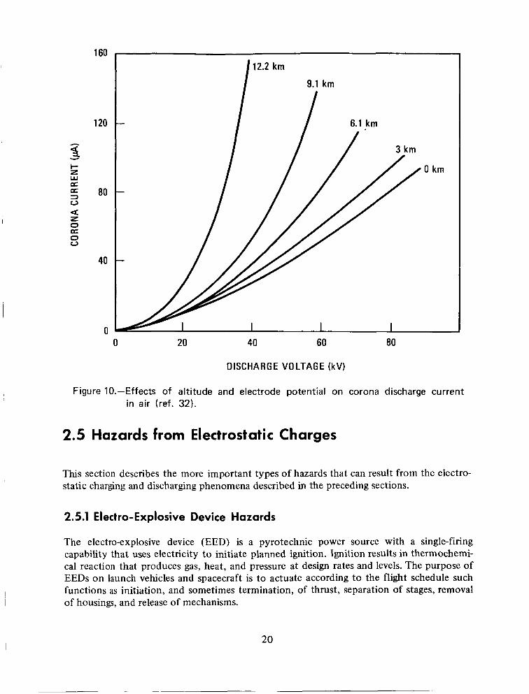
Corona discharge usually is associated with nonuniform fields or assymetrical electrodes that cause concentrations of high fields at one or both electrodes. Corona discharge occurs when the entire gap of the gas medium is not spanned by the breakdown. Unsteady and fluctuating currents, increasing linearly and becoming steadier with increased potential, show a bluish light in the region of breakdown. The luminosity, which may be in a form such as a halo, a glow, or wavering rays, is the source of the term corona. The corona dis- charge current depends on altitude and electrode potential as shown in figure 10.
Corona discharges can precede an electric arc in many cases if the rate of discharge is in- creasing (sec. 2.4.2). Corona creates radio interference noise in a broad spectrum (fig. 9). The rapid fluctuations of the corona that result in electromagnetic waves have rates of current change on the order of 1 to 10 A/ps (ref. 31).
2.4.2 Arc Discharge
An arc discharge is manifested by small sparks that occur when dieiectric breakdown is com- plete across the space between oppositely charged bodies. The sparks (with rise times of microseconds and peak currents of hundreds of amperes) create higher frequency distur- bances than the corona (fig. 9). The heat and light that are generated lead to secondary effects which depend on the configuration and nature of the electrodes. Each charged body itself will experience pitting and deterioration at the origin of the arc. Dc power supplies, especially of 1 or 2 kV, have been found quite vulnerable to arcing. Once an arc has oc- curred, the ionized gas provides a low resistance path that permits high currents to flow at relatively low voltages.
To prevent arc discharge, the most sfisceptible parts of electrical circuits sometimes are imbedded in a solid dielectric with a high breakdown value. Another alternative is to keep the power supply turtled off until the flight vehicle has passed through the critical range of altitudes (fig. 8).
2.4.3 Surface Streamers
Electrical discharge can occur across the surfaces of dielectrics. These discharges involve breakdown at the dielectric surface because of lowered dielectric strength of the surface molecular arrangement of the material or because of adhering impurities. (Surface streamers are not to be confused with the currents or streamers through a gas that may precede an arc discharge, discussed in section 2.4.2.) Triboelectrification of a dielectric, such as results from precipitation on a plastic vehicle surface is a common cause of surface streamers.
Radio noise is generated by surface streamers as well as by corona and arc discharges. How- ever, because of the slower rise time, the noise spectrum does not extend to as high fre- quencies, as shown in figure 9.
19
160
120
5 -c
I- z w a
80 3 0
z 0 U 0 0
a
40
0
12.2 km
9.1 km
0 km
I I I I
0 20 40 60 80
DISCHARGE VOLTAGE (kV)
Figure 10.-Effects of altitude and electrode potential on corona discharge current in air (ref. 32).
2.5 Hazards from Electrostatic Charges
This section describes the more important types of hazards that can result from the electro- static charging and discharging phenomena described in the preceding sections.
2.5.1 Electro-Explosive Device Hazards
The electro-explosive device (EED) is a pyrotechnic power source with a single-firing capability that uses electricity to initiate planned ignition. Ignition results in thermochemi- cal reaction that produces gas, heat, and pressure at design rates and levels. The purpose of EEDs on launch vehicles and spacecraft is to actuate according to the flight schedule such functions as initiation, and sometimes termination, of thrust, separation of stages, removal of housings, and release of mechanisms.
20

The initiating circuits must be protected from stray voltages that might result from electro- static discharging or induced currents. Such circuits include the command input to the firing device. Because the command circuit may be more sensitive than the EED, it should be protected and desensitized as well as the line to the EED.
There are three main types of EEDs (named by their method of actuating ignition): the resistive bridgewire, exploding bridgewire, and capacitive discharge.
2.5.1.1 Resistive Bridgewire
For this type of EED, ignition is accomplished by the heat generated in the bridgewire by a comparatively low voltage (0.1 to 5 V) at modest current levels (0.05 to 5 A). This type of EED is most frequently used in space operations because it can be protected against electro- static charges and it does not put great weight and volume requirements on the vehicle or spacecraft. The electrostatic sensitivity of this type of EED is presented in reference 34; the relation of sensitivity test results to probabilities of successful firing is presented in reference 35.
Cunent siaiwf-the-ait test iequhex,enis fOi ‘iijdge-W-iie EE”vs are “used on e;ec?io- static hazards of contact with the human body and exposure to stray magnetic fields (ref. 36). The hazard from the human body is simulated in tests in which the resistive bridgewire must tolerate 25000 V through a 500 pF condenser with a 5000 !L? resistor without ignition or damage. To test against stray electric and magnetic fields, 1 A or 1 W is applied for 5 minutes to see if ignition occurs.
2.5.1.2 Exploding Bridgewire
The exploding bridgewire EED requires both high voltages (2000 to 3000 V) and high power (20 to 1000 W) for ignition. The pulse vaporizes the bridgewire and the associated explosion actuates the main EED power source. This type of initiator poses little danger of initiation by electrostatic charges but the launch vehicle is burdened with a relatively heavy power supply of about 3.6 pounds.
2.5.1.3 Capacitive Discharge
This EED is ignited by a capacitive discharge of typically about 20 V. It is commonly used where only low energy is available. It is highly sensitive to electrostatic charging. If this type of EED is in a vehicle or spacecraft design, particular care must be taken to guard against stray electrostatic discharges. EED’s that can be fired by less than 1A or 1 W should be avoided for vehicles or systems when they can be hazardous to life.
2.5.2 Combustible Gases
Combustible gases may collect in several ways. Battery charging releases hydrogen gas. Venting of propellant gases, such as the automatic venting of cryogenically-cooled gases, can result in concentration of vapors in a closed compartment. Liquid hydrogen-oxygen fuel cells also are potential sources of explosive gas mixtures.
21

An electric discharge in a combustible mixture of gases may result in an explosive combina- tion because of the injection of localized and instantaneous energy. The minimum energy* needed for ignition varies with the mixture ratio of pairs of gases that are capable of exo- thermic reaction. If gas A or gas B is alone, a spark cannot cause a combustion reaction; as one gas is mixed with more and more of its reactive partner, the required ignition energy decreases to a minimum and then increases as still more of the reactive partner is added (fig, 11). The gas pressure of the mixture is also important. The minimum ignition energy for a hydrocarbon-oxygen mixture ranges from 0.002 to 0.004 mJ at 1 atmosphere, and increases to 0.02 to 0.04 mJ at a pressure of 1/3 atmosphere (ref. 8).
Another factor determining whether a discharge will result in chemical reaction is the ignition-quenching distance. This is the smallest distance over which a discharge of the minimum ignition energy will initiate a reaction. Across smaller gaps, discharges of greater amounts of energy may expend enough energy in the two conductors so that ignition is quenched.
2.5.3 Electronics
Surge currents initiated by electrostatic charge and direct or indirect surge currents of lightning can cause a variety of damage in electrical circuits. The heat effect of excessive current may cause fusing, burning, and melting of insulation on wires and thereby short or open circuits. Also, solder connections can be broken by surge current heating.
The most susceptible parts of electrical circuits are solid state devices. The microsecond pulse induced by lightning is within the response time of these devices. A relatively low voltage across the device can result in permanent damage.
2.5.4 Communications
On-board electrostatic effects cause radio noise as described in section 2.4. Atmospheric precipitation also interferes electrostatically with transmissions between Earth and space- craft (ref. 38).
2.5.5 Persons
Electrostatic discharge may be hazardous to persons. A mild shock could cause a reflex action with secondary effects when a person is working on a delicate mechanism or is in cramped quarters. A discharge of about 0.25 J gives a heavy shock. An electrostatic charge of 10 J can be hazardous to life but is rarely encountered.
Under certain conditions, the human body can store a charge equal to that of a 500 pF capacitor at 18000 V (ref. 36). A most dangerous hazard to persons is handling electro- explosive devices sensitive to the electrostatic charge in the human body.
e
*Minimum energies needed for ignition of different gas mixtures is given in NACA 1300, Basic Considera- tion in the Combustion of Hydrocarbon Fuels with Air, ed. by H. C. Barnett and R. R. Hibbard, 1957.
I* 22

I r - --- 1 40.0
20.0
10.0
8.0
6.0
4.0
2.0
1.0
0.8
0.6
0.4
0.2
I I I I I I I I I I I I I I I I I I I I I I I I I I I I
I I I I I I I I I I
I I
IGNlTlO N
NO IGNITION
UPPER LIMITS OF FLAMMABILITY I
I I I I I I I I I
i
I 1 I I I I I I I I I i I I I I I I I I I I I I I I I ,I
I
6 8 10 12 14 16
VOLUME OF METHANE (%)
Figure 11.-Minimum energy release to cause ignition of a methane-air mixture (ref. 37).
23

2.6 Methods for limiting Electrostatic Charge Problems
2.6.1 Prelaunch Operations
Numerous possibilities for electrostatic charging exist during the preparation for space flight. The charging mechanisms are essentially those that have been discussed in the preced- ing sections, but the sources and the extent of the effects can take various forms. High voltage electrical equipment can contain hazardous accumulations of charges even though disconnected. Incidents of electric shock and high voltage damage to circuits and instru- ments can generally be prevented by application of the principles given in section 2.5.3.
The fueling of liquid rockets involves the flow of liquids through pipes and generation of considerable electric charge. Grounding straps generally are employed to prevent hazardous charge buildup. Spaces should be vented where combustible gas mixtures might otherwise accumulate.
Protection of the launch vehicle on the launch pad from lightning has received serious attention (ref. 39). The umbilical tower alongside the vehicle is designed with sufficient height and conductivity to ground to act as a lightning rod. To provide low ground resis- tance and ensure that all points of the launch complex assume the same potential during a stroke, ground rods are installed. These rods distribute lightning current and shield the rest of the launch complex. Tall grounded objects form cones of protection; the peak of the cone is the top of the grounded object and the radius of the cone’s base is the object’s height (ref. 40). The layout of the launch complex utilizes these cones wherever possible.
2.6.2 On-board Sources
Methods for handling the on-board sources, reviewed in section 2.2, may be grouped into two categories: control of charge accumulation and reduction of discharge effects.
2.6.2.1 Control of Charge Accumulation
Control of charge accumulation on conductors can be accomplished by grounding. Ground- ing should be continuous across flexible joints, lubricated mating surfaces, and insulation. Designers frequently include a grounding point or tab to permit temporary grounding of conductive components during assembly. When a conductor must be insulated from the ground, the insulator should have as high a conductivity as the application permits. Surface agents, such as semiconducting ceramic glazes, are frequently employed. Velostat, a plastic sheeting used to provide temporary physical protection, has grcunding capability to prevent charge accumulation,but should be used with care since it degrades with age and continued use.
Charging of vented or dumped liquids (sec. 2.2.3) can result in attraction to a spacecraft sur- face. The venting of liquids has been studied in the Skylab program for possible electro- static hazards (ref. 41). Routing of vents away from sensitive surfaces and control of venting velocity are appropriate countermeasures.
24

2.6.2.2 Reduction of Discharge Effects
The second approach to reducing electrostatic hazards is to minimize the effects of possible discharge. Often, a spark gap can route the arc along a safe path. An ion source such as a radioisotope can ionize the air so as to allow breakdown at a lower and safer potential. Wire stubs are frequently added to flight vehicles to provide points for corona discharge. Many tantalum (for ductility and strength) wires were bolted to the Minuteman missile at the base of the first and second stage motors. The free ends of the wires provided points for corona discharge to prevent Minuteman failures such as described in section 2.1.3. Figure 12 shows the design finally adopted.
2.6.3 Lightning Protection
Three lightning models are given in NASA SP-8084, revision of June 1974 (Surface Atmos- pheric Extremes-Launch and Transportation Areas). Model 1 is for a very severe discharge, Model 2 is for a discharge with a 98 percentile peak current, and Model 3 is for a discharge with an average peak current. For application of the lightning models to manned space vehicle design, JSC-07636 of September 1973 (Space Shuttle Lightning Protection Criteria Document) is useful.
2.6.3.1 Weather Watch
*, Avoidance of lightning strokes begins with a weather watch, provided for space flights by the National Weather Service, the Air Force, and the Navy. Weather forecasts are developed for the period of exposure when the vehicle is moved to the launch complex, the work period at the launch complex, and the moments of exposure during the launch. Location and movement of nearby weather fronts, and the on-site atmospheric electric field are kept under surveillance. When field monitoring or weather observations indicate excessive risk at launch time, countdown is delayed. The predicted passage of a large cloud cell across the launch area is of particular concern. The weather watch also is in operation during reentry of manned spacecraft and selects locations where the risk of lightning or large field gradients will be negligible.
2.6.3.2 Vehicle Design
In design, the possibility of one or more lightning strokes while the vehicle is on the launch pad is considered. Protection d u h g this phase is provided by proper bonding of the space vehicle’s outer skin, i.e., bonding with a resistance no greater than 25 mS1 for protection against Lightning Model 1 (sec. 2.6.3). Protection by design measures during the launch phase may not be possible because of the greater vulnerability of both liquid and solid en- gmes while burning. Therefore careful attention is gwen to selection of suitable weather conditions for launch (sec. 2.6.3.1 ).
‘Protection against currents induced inside the space vehicle is of concern. The currents that flow as a. resclt of a lightning stroke may not act as dc currents in their inductive effects because of high frequencies. JSC-07636 (Space Shuttle Lightning Protection Criteria Document) gives information on shielding, design of protective circuits, and wave shapes of induced currents.
25

TOP VIEW
SHARP POINT 30" TO 60" ANGLE 1
/
SIDE VIEW
1.30 IN. I
r
Figure 12.-Construction of corona dischargers to relieve electric potential on Minuteman I I (ref. 42).
26

3.
3.1
The
CRITERIA
Assessment of Electrostatic
hazards from electrostatic effects to spacecraft, launch vehicles, and ground operations shall be assessed and their effects on personnel safety and the mission objective determined. For each area of consideration, the assessment must take into account extremes of ambient conditions, charging mechanisms, and system performance to estimate the magnitude of electrostatic charges. Both experimental measurements and mathematical modeling may be useful in the foregoing analysis. Specific consequences of electrostatic charging, such as inadvertent firing of electroexplosive devices or disruption of radio guidance, shall be con- sidered. When the assessment indicates that an unacceptable hazard or combination of hazards might exist, suitable measures must be provided in the design or operational pro- cedures. When feasible, laboratory tests shall be performed to confirm the effectiveness of the design and operationai procedure in minimizing deieterious eiecrrosratic effects.
3.2 Control Objectives
Design of the flight vehicle and spacecraft shall be such that the effects of electrostatic charge accumulation and discharge from any source shall not interfere with performance or safety of the mission.
Design objectives shall be specific to the final design of spacecraft and launch vehicle. When data on exact magnitudes of effects are not available, such data shall be requested as part of the test program. If needed data can not be acquired, conservative estimates shall be used. Design considerations shall be documented and reviewed.
3.2.1 Fabrication and Test
The assembly and test procedures for spacecraft and launch vehicle shall include appropriate measures against charge buildup and sparking. Large metal components shall be grounded to prevent charge accumulation. Electrical equipment shall be grounded. All grounds shall be tested for continuity after installation and periodically when breakage from vibration or other testing appears likely.
Triboelectric effects shall be minimized, e.g., care shall be taken to avoid buildup of charge when polishing dielectric surfaces such as lenses, transparent insulators, and plastic parts. Moving belts, insulators, astronauts’ suits, and other dielectrics with potential triboelectri- fication shall be designed and tested with this hazard in mind.
27

Tests shall be performed on all high voltage components to determine whether sparking occurs under expected environmental conditions and to ensure that circuits will survive intentional and unintentional turn-on.
Low voltage electronic components, especially those in the guidance and control system, shall be tested comprehensively because of their sensitivity to stray discharge and their crucial role in mission success.
Tests for electrostatic hazards shall be performed on systems that include moving dielec- trics, e.g., the motion of tape in tape recorders or film in cameras. Charge buildup during operation in the space environment shall be measured where detectable and the associated hazards shall be determined.
3.2.2 Flight
The extent of electrostatic charging of the flight vehicle, the spacecraft, and subsystems by external and internal charging mechanisms shall be calculated when possible. The deleterious effects of charging shall be assessed. Appropriate measures shall be implemented when indicated by the seventy of the hazards that are determined in this assessment.
Special attention shall be given to the following items in the performance of this analysis:
accidental ignition of explosive devices by discharge pulses" provision for installation on the launch pad of sensitive initiating elements of ordnance
currents induced in subsystems by lightning strokes" * 0 currents induced in subsystems by arcing of high voltage units
ignition of flammable vapors or materials by discharges deterioration of insulation and other dielectrics due to breakdown effects of potential, such as attraction of dust, corona discharge, and charged particle attraction
0 effects of discharge pulses on communications
devices, solid propellant devices, and destruct charges ( r 4 39).
- ~
*Reference 39 establishes categories A and B for explosive devices and provides specific procedures for handling each type. In category A are those devices that if fired unintentionally could cause death or injury to persons or major property damage by themselves or through a train of events.
**NASA SP-8084, revision of June 1974, gives three lightning models (sec. 2.6.3).
28
3.3 Management for Electrostatic Charge Control
Management practices to avoid electrostatic hazards are of particular significance because their existence may be unsuspected before investigation. Personnel safety should have highest priority. The status of the electrostatic control effort should be reported periodi- cally to project management. The objective should be to discover possible electrostatic hazards and plan preventive measures early in the program. This may be carried out in three phases.
First, management should place emphasis on electrostatic hazards during the design phase by assignment of individual responsibility for (a) assessment of electrostatic effects, (b) development of specific standards for electrostatic control consistent with the mission, and (c) application of the foregoing standards to design, fabrication, assembly, testing, launch operations, and flight. Second, management should initiate tests and measurements to ensure that (a) the systems as designed satisfy the foregoing standards, and (b) the flight system as assembled also meets these standards. Third, management should include a system for review of unexpected electrostatic effects encountered during operational tests of the hardware.
4. RECOMMENDED PRACTICES
4.1 Design
4.1.1 Grounding Obiectives
Many internal electrical hazards can be eliminated by electrical grounding to the vehicle shell. Ground wires should be used for individual systems when appropriate. Wires should be adequate to carry a surge of current without mechanical damage. Grounding is normal practice for electrical circuit design and should not be neglected in design of a mechanical apparatus or an astronaut’s suit. As discussed in section 2.2, a charge can be generated almost anywhere. The amount of static charge that an electrically isolated man can ac- cumulate is sufficient to ignite combustible gas vapors unless his suit is grounded. A high resistance ground is usually satisfactory to discharge surfaces susceptible to electrification by contact.
4.1.2 Shielding by the Vehicle Shell
Many internal electrostatic hazards can be eliminated by electrical bonding of the vehicle shell. All sections of the vehicle’s outer shell should be bonded together to permit large quantities of electric charge to distribute across the shell by conducting paths. The bonded shell of the space vehicle then acts as an electrical shield to protect internal structures from lightning and atmospheric electricity. However, induced currents can develop when lightning
29

strikes. The effects of such currents should be assessed for the lightning models of NASA SP-8084 (sec. 2.6.3).
4.1.3 High Voltage Electronics
High voltage devices include high voltage generators, photomultiplier tubes, video tubes, and charged particle detectors. High voltage devices may have charged components at potentials that are significantly different from those of the spacecraft structure. Electrical discharge is a special hazard associated with such devices; lesser electrostatic effects are ion attraction, dust attraction, and dielectric strain.
Because a charge is unavoidable on the ungrounded side of a high voltage device, precautions must be taken to reduce electrostatic effects. The tendency to discharge can be minimized by removing sharp edges, turns, and points on the high voltage conductors. Recommended steps to prevent the contact of the gaseous atmosphere with the high voltage conductors are potting or hermetic sealing and pressurization. For missions of long duration, potting is much preferred. If the high voltage device is to be accessible for repair, potting com- pounds should be selected that can be removed partially to expose the defective component and then be replaced by new material which will bond completely to the old. When potting compound is used, a prime requirement is that it must adhere completely to all conductors to prevent air gaps or voids because they could be locations for possible breakdowns. Care should be taken to avoid entrapping bubbles of gas in potting.
Units should be vented to the outside vacuum of space for outgassing. Grounded shields should be used over the insulation of high voltage cabling to contain strong electric fields within the cable and prevent external structures from inducing a discharge (ref. 43).
4.1.4 low Voltage Electronics
The low voltage circuits whose performance would affect mission success should be care- fully assessed in the design stage against electrostatic hazards, particularily induced current pulses. Guidance and control circuits are of particular concern. The hazards of electrostatic buildup and discharge are often less well-recognized for low voltage electronics than for high voltage electronics.
Low voltage devices, the normal electronics of a space vehicle, should be designed to minimize coupling with high voltage devices, corona discharges, and lightning strokes. The conservative practices of short cables and conductive sheathes should be employed. Sensitive components, notably solid state devices, should be protected from high frequency pulses. A resistor-capacitor circuit in the lead to the base of a transistor can protect it against such pulses. When a critical component or circuit appears vulnerable, redundant circuits, isolated from each other, should be provided:
For the exterior of the spacecraft, the plasma of space acts as a conductor that should be considered in the design of exterior electronics. For example, exposed terminals of solar cells can collect electrons and increase the negative charge of the spacecraft. Therefore, the
30

positive side of the solar cell should be grounded and terminals should be insulated if feasible. In general, positive leads should be disconnected with a relay or other device when they are exposed to space.
4.1.5 Dielectrics
Electrostatic charge on a dielectric can lead to radio noise and possible hazards from arcing. In some cases, this may be prevented by coating the dielectric with a conducting material. Stannous oxide, which is conductive yet transparent, should be considered for glass surfaces. Velostat, a carbon-impregnated polyethylene, may be used where polyethylene can cause an electrostatic buildup, but velostat does degrade with age and continued use. Metal threads or wires, as mentioned in section 2.2.1 , can reduce dielectric problems in fabrics.
Dielectrics in capacitors should be tested for their dielectric strength. If a breakdown occurs during operation, the discharge can tear a hole in the dielectric and reduce the capacitance. A major loss of dielectric material would cause the capacitance to approach that of an air gap capacitor.
Dielectrics used for insulation of high voltazes should have a substantial!;^ higher rating thar, is required in ground-based systems. It is not unusual to require 2 to 5 times the normal rating.
Insulation should fit snugly onto conductors and be free of voids. Gas trapping underneath the dielectric or as bubbles in the material should be avoided. Gas pockets in wire coatings, potting compounds, or conformal coatings are particularly hazardous because the boundary between a solid dielectric and a gas of lower dielectric constant gives rise to an increase in electrical stress on the gas. This could cause a breakdown in the gas and heating and decomposition of adjacent insulation.
4.1.6 Electro-Explosive Devices
These devices, including squibs, igniters, spin and tumble rockets, explosive bolts, destruc- tors, detonators, and other pyrotechnic units aboard space vehicles, should be thoroughly protected from electrostatic effects. The typical resistive bridgewire EED is ignited by an electric pulse, of low voltage (0.1 to 50 V) and low current (0.05 to 5 A). An electro- magnetic pulse generated by nearby transmitters or an electrostatic discharge can readily induce a current within an unprotected sensitive EED and ignite it (ref. 39). Therefore, tests should be performed to determine sensitivity to nearby electrostatic discharges as well as to electrical discharges to the EED itself.
To prevent EED ignition, it is recommended that the pyrotechnic should be completely shielded from external sources. The conductive parts of the device should be electrically bonded together either by mechanical contact, connecting wires, or conductive resins. Selec- tion of a high-resistance material should be made for use between the firing circuits and the case to dissipate any accumulation of charge without affecting proper functioning of the EED (ref. 35).
31

4.1.7 Installation of Ordnance Devices
Ordnance devices, such as solid propellant rocket motors and destruct charges, should be designed so that the sensitive initiating elements can be installed just prior to hookup on the launch pad. The ordnance devices should be accessible to facilitate installation and electrical connection as late as possible in the launch countdown (refs. 36 and 39).
4.2 Testing
Extensive testing of spacecraft and launch vehicle is essential. Electrostatic testing should be based on the measurement of the hazards and effects described in sections 2.2, 2.3, and 2.4 Although it is often not feasible to simulate certain extreme charging mechanisms, notably the effects of rocket exhaust, lower levels can often be simulated and extrapolated to the expected level. This is useful for the effects of lightning* and sustained operation under space conditions. When such an approach is necessary, the analysis should be documented and reviewed. An important factor to be considered in an extrapolation is that discharge is a threshold phenomenon. The electric fields during flight operations can be evaluated by scaling the measured field. To account for discharge and discharge effects, however, requires an analysis of dielectric strength, geometry, and other factors as described in section 2.4.
High voltage electrical systems should be tested for susceptibility to discharge at sustained critical pressure and also under a hard vacuum ( torr) of sufficient duration to ensure that any small bubbles within an encapsulated circuit reach critical pressure (ref. 43).
X-ray photography is recommended if voids in potting are to be investigated. An alternative is to use transparent potting compound so that a microscope can be used to check for gas bubbles.
Dielectric bodies should be tested to determine their charge retention. A measurement should be made of the time constant for removal of charge. The dielectric strength of the material should be verified by measurement on the batch used.
Application of voltage to a system requires certain precautions. The connectors and cabling to the test specimen must be designed to carry high voltages. Special connectors and vacuum feedthroughs should be used when the voltages do not exceed about 150 V. Above this level, it is recommended that the high voltage supply be placed in the vacuum chamber and hard-wired to the system under test. However, the power supply must first be made dis- charge free. When testing a circuit with multiple high voltage supplies, it is recommended that separate low voltage supplies be used so that discharge transients or noise are not coupled directly to the high voltage circuitry (ref. 43).
*A number of lightning simulation techniques are discussed by D. W. Clifford in the 1973 IES Proceedings (Anaheim, Calif.), April 2-5, 1973, pp. 388-396.
32

Spacecraft launch operations have been extensively studied for electrostatic hazards ranging from arcing that results from charge buildup during prelaunch operations to the hazards of atmospheric electricity. It is recommended that management of a launch take full cogni- zance of the precautions which have been developed. Close and frequent coordination of information-gathering groups and launch operation groups is essential. There should be flexibility in launch dates to avoid adverse atmospheric conditions. Rescue and emergency backup personnel should be trained and available in the event of electrical shocks, lightning damage, or fires of electrical origin.
Electrostatic hazards should be taken into account in operational control of the flight vehicle after liftoff and the spacecraft after its separation. It will be necessary in some designs to keep certain high voltage equipment turned off until above the ionosphere to forestall arcing at the altitude where the Paschen minimum occurs in the atmosphere. Buildup of electric potential as a result of onboard and external sources described in section 2 can be expected. The general hazards described in this document may not include a hazard unique to a particular mission, as for example the docking of a spice sbuttle (ref. 44j. T i e unique aspects of each Tight mission should be explored for electrostatic hazards. If neces- sary, the system design and mission operations should be modified to control serious electrostatic effects that are revealed.
33


1
2.
3.
4.
5 .
6.
7.
8.
9.
10.
11.
12.
13.
REFERENCES
Shea, J. J.; and Carpenter, K. H.: Ambient Plasma Effects Upon Electrostatically Expanded Mesh Structures, Cosmic Inc. Report 178 under NAS5-10477, January 1968.
Cohn, G. I.: Electrostatic Charging and Discharging Models and Analysis for Ranger Spacecraft During Launch, TR 32-77 1, Jet Propulsion Laboratory, August 1965.
Miller, J. S . : Electrostatic Ignition of X248 Rocket Motors, DM-1934-EZ-la, Cornel1 Aero. Laboratory, March 1965.
Andrus, P. G.; and Walkup, L. E.: Electrostatic Hazards During Launch Vehicle Flight Operations, BMI-NLVP-TM-69-1, Battelle Mem. Inst., February 1969.
Godfrey, R.; Mathews, E. R.; and McDivitt, J. A.: Analysis of Apollo 12 Lightning Incident, MSC-01540, February 1970.
DeForest, S. E.: Spacecraft Charging at Synchronous Orbit, J. Geophys. Res., vol. 77, 1972, p. 65 1.
Henry, P. S. H.: Survey of Generation and Dissipation of Static Electricity, Brit. J. of Applied physics, Suppl. 2, March 1953.
Potter, A. E., Jr.; and Baker, B. R.: Static Electricity in the Apollo and Skylab Space- craft, AFAL-TR-72-325, Wright-Patterson AFB, December 1972.
Vance, E. F.; Seely, L. B.; and Nanevicz, J . E.: Effects of Vehicle Electrification on Apollo Electro-Explosive Devices, SRI Proj. 5 10 1, Stanford Res. Inst., December 1964.
Molmud, P.: Frictional Electricity in Missile Systems, J. Amer. Rocket SOC., January 1959.
Nanevicz, J. E., et al: Low-Altitude, Long-Range, All-Weather Vehicle Interference Investigation, AFAL-TR-65-239, Wright-Patterson AFB, December 1965.
Aronowitz, L. : Electrostatic Potential Generated by Rockets on Vehicles in Space, IEEE Trans. on Electromagnetic Compatibility, December 1968.
Vance, E. F.; and Nanevicz, J . E.: Rocket Motor Charging Experiments, AFCRL-66- 497, June 1966.
35

14. Capener, E. L., et al,: Studies on Ionization Phenomena Associated with Solid Propel- lant Rockets, AIAA Sixth Solid Propellant Conf., Washington, D. C., February 1965.
15. Aronowitz, L. : Rocket-Engine-Generated Voltage as a Source of Electromagnetic Inter- ference and Electronic Component Damage on Interplanetary Vehicles, IEEE Space Electronics Symp., Miami Beach, Fla., November 1965.
16. Lenard, P.: Ueber der Elektrizitat der Wasserfalle, Anna1 der Phys., (Leipzig), 46, 548-636, 1892.
17. Strawson, H.; and Lewis, A.: Electrostatic Charging in the Handling of Aviation Fuels, AGARD Aircraft Fuels, Lubricants, and Fire Safety, August 197 1.
18. Loeb, L. B.: Thunderstorms and Lightning Strokes, in Modern Phys. f o r the Engineer, McGraw Hill Book Co., New York, 1954.
19. Daniels, G. E.: Atmospheric Electricity Criteria Guidelines for Use in Space Vehicle Development, NASA TM X-64549, August 1970.
20. Uhlig, E. R.: Comparison of Calculated and Measured Lightning Effects on Space Vehicle Launch Complexes, Lightning and Static Electricity Conf., Air Force Avionics Laboratory, December 1968.
21. Fitzgerald, D. R.: Aircraft and Rocket Triggered Natural Lightning Discharges, Light- ning and Static Electricity Conf., Air Force Avionics Laboratory, December 1970.
22. Bauman, W. A.; Palmer, B. L.; and Krivo, S. J.: Surface Atmospheric Extremes (Launch and Transportation Areas), NASA SP-8084, May 1972.
23. Hill, E. L.; and Robb, J. D.: Pressure Pulse from a Lightning Stroke, J. Geophys. Res. 73, 1883, 1968.
24. Hill, E. L.; and Robb, J. D.: Spectroscopic and Thermal Temperatures in the Return Stroke of Lightning, J. Geophys. Res. 75, 3426, 1969.
25. Yaffee, M. L.: Air Transport Lightning Strikes Studied, Av. Week and Space Tech., December 1 1 , 1972.
26. Nanevicz, J. E.; Vance, E. F.; Tanner, R. L.; and Hilbers, G. R.: Development and Testing Techniques for Precipitation Static Interference Reduction, SRI Proj. 2848, Stanford Res. Inst., January 1962.
27. Nanevicz, J. E.; Chown, J. B.; Vance, E. F.; and Martin, J. A,: SRI Participation in Voltage Breakdown and Rocket Charging Experiments on Nike-Cajun Rocket AFCRL AD 6.841, AFCRL-66-588, August 1966.
36

28.
29.
30.
31.
32.
33.
34.
35.
36.
37.
38.
39.
40.
41.
Langmuir, I.; and Mott-Smith, H., Jr.: Studies of Electric Discharges in Gases at Low Pressure, General Electric Review, 27,449455, 1924.
West, W. S.; Gore, J. V.; Kasha, M. A.; and Bilsky, H. W.: Spacecraft Charge Buildup Analysis, NASA SP-276, 197 1.
Whipple, E. C., Jr.: The Equilibrium Electric Potential of a Body in the Upper Atmo- sphere and in Interplanetary Space, NASA Goddard Space Flight Ctr. X-6 15-65-296, June 1965.
Loeb, L. B.: Electrical Coronas. Their Basic Physical Mechanisms. University of Calif. Press, Berkeley, 1965.
Cierva, J. de la; and Gillis, H. J.; and Wilson, P. B., Jr.: Theoretical Analysis of Aircraft Electrostatic Discharge, USAAVLABS Tech. Report 65-53, August 1965.
Truax, R. L.: Electrostatic Charging and Noise Quieting, Lightning and Static Elec- tricity Conf., Air Force Avionics Laboratory, December 1970.
Kabik, I. : Nondestructive Testing, Proc. NASA Symp. on Electroexplosive Devices, April 1967.
Miller, J. S.: Electrostatic Sensitivity of Electro-Explosive Devices, DM-1934-EZ-3, Cornel1 Aero. Lab., April 1965.
Hannum, E. E.: Current Testing Practice, Proc. NASA Symp. on Electroexplosive Devices, April 1967.
Litchfield, E. L.: Spark Ignition, Lightning and Static Electricity Conf., Air Force Avionics Laboratory, December 1968.
Ippolito, L. J.: Effects of Precipitation on 15.3- and 3 1.65-GHz Earth-Space Trans- missions with the ATS-V Satellite, Proc. IEEE 59, 2, February 197 1.
Safety Range Mamal, AFETRM 127-1 , Air Force Systems Command, U. S. Air Force, November 1966.
Fisher, F. A.; and Blalock, T. J.: Protection of Ground Space Facilities from the Effects of Lightning, Lightning and Static Electricity Conf., December 1970.
Beaver, H. E.; and Ellison, R. W.: The Role of Electrostatics in Skylab Contaminant Behavior, AFAL-TR-72-325, Wright-Patterson AFB, December 1972.
37
42. Axtell, J . C.; and Oakberg, T. C.: An Electrostatic Charge Phenomenon Associated with Minuteman Missile Flights, AFAL-TR-68-290, May 1969.
43. Paul, F. W.; and Burrowbridge, D.: The Prevention of Electrical Breakdown in Space- craft, NASA SP-208, 1969.
44. Gregory, R. 0.: Agena-Gemini Electric Charge Monitor, Proc. Instrument SOC. of Amer., National Aerospace Symp., May 1966.
38

APPENDIX A ELECTROSTATIC SYMBOLS
AND COMMON UNITS
The International System of Units (SI) provides conventional symbols for the units em- ployed in calculation of electrostatic effects. Listed below are some of the symbols, units, and conversion factors that relate them to some familiar units and fundamental quantities.
SYMBOL
S
m
m2 N
A
C F
J
V
8 eV
QU ANT I TY UNIT MULTIPLY BY
time second - length meter 39.37
area square meter 1550 force newton 0.225
current ampere 1 charge coulomb 6.25 x 10l8 capacitance farad 1 O6 energy joule 9.48 x 10⁻⁴
0.239
potential volt 300 resistance ohm -
kinetic energy electrovolt 1.60 x loe1’
TO OBTAIN
-
inches
square inches
pounds
cou lom bdsecond
electrons
microfarads
BTU ca I or ies
statvo Its
joules
SI prefixes and symbols used to denote decimal multiples of quantities follow.
Multiples
1 09 1 o6 103 10-3 10-6 10-9 10-l2
Prefixes
gigs mega
kilo
milli
micro
nano
pic0
Symbols
G M k
m
P n
P
39


APPENDIX B SOME FORMULAS FOR
ELECTROSTATIC CALCULATIONS
The following formulas from electrostatic theory are presented to provide a ready reference. The symbols have been defined in appendix A. Subscripts on symbols refer to their value for each of the physical items considered.
Resistors in series - 52 = a1 + a2 + a3 + * - - -
Resistors in parallel - 1 +- + . . . . +- 1 1 - 1 52 521 522 523 - - -
- 1 - - - + - + - + 1 1 1 . . . . F Fl F2 F3
Capacitors in series -
Capacitors in parallel - F = F, + F2 + F3 + e - - -
Coulomb’s Law - N = (C1C,)/(4mm2)
where N is the force between charges C, and C, , separated by distance m, in a medium of permittivity E.
E = kg0
where k equals unity in air and space and is the measured dielectric constant in other mediums, and go = 8.84 X F/m.
Potential from a distribution of charges -
-k m, c, + - c3 + ...I m3
where ml is the distance of charge C, from the point of potential V.
Definition of capacitance - F = C/V
Electrostatic energy stored in a capacitor -
J = y F V 2 1
41
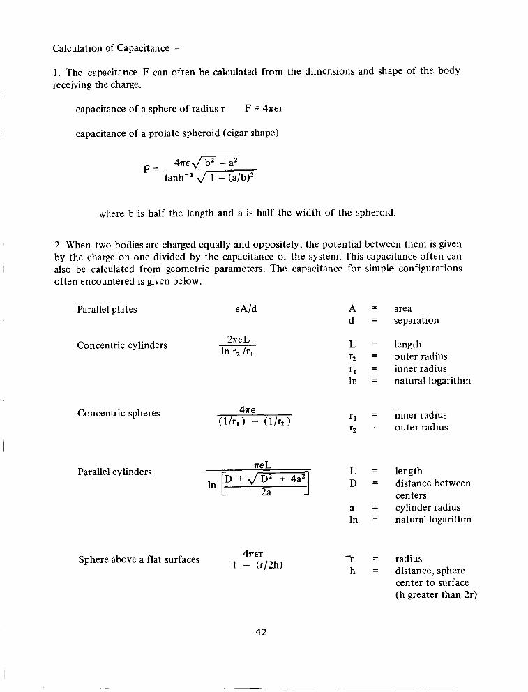
Calculation of Capacitance -
1. The capacitance F can often be calculated from the dimensions and shape of the body receiving the charge.
capacitance of a sphere of radius r F = 4ner
capacitance of a prolate spheroid (cigar shape)
4ne J-iT7 tanh-' d w F =
where b is half the length and a is half the width of the spheroid.
2. When two bodies are charged equally and oppositely, the potential between them is given by the charge on one divided by the capacitance of the system. This capacitance often can also be calculated from geometric parameters. The capacitance for simple configurations often encountered is given below.
Parallel plates eA/d
Concentric cylinders
Concentric spheres
Parallel cylinders
Sphere above a flat surfaces
2ne L
ne L p + JF 3
42
A d
L r2 r1 In
r 1 r2
L D
a In
- r h
area separation
length outer radius inner radius natural logarithm
inner radius outer radius
length distance bet ween centers cylinder radius natural logarithm
radius distance, sphere center to surface (h greater than 2r)
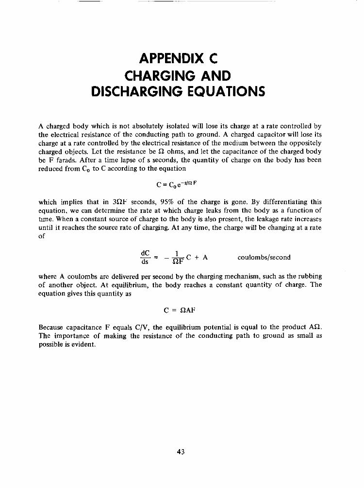
APPENDIX C CHARGING AND
DISCHARGING EQUATIONS
A charged body which is not absolutely isolated will lose its charge at a rate controlled by the electrical resistance of the conducting path to ground. A charged capacitor will lose its charge at a rate controlled by the electrical resistance of the medium between the oppositely charged objects. Let the resistance be 52 ohms, and let the capacitance of the charged body be F farads. After a time lapse of s seconds, the quantity of charge on the body has been reduced from C o to C according to the equation
which implies that in 352F seconds, 95% of the charge is gone. By differentiating this equation, we can determine the rate at which charge leaks from the body as a function of time. When a constant source of charge to the body is also present, the leakage rate increases until it reaches the source rate of charging. At any time, the charge will be changing at a rate of
coulombs/second 1 - - dC - --C + A ds S2F
where A coulombs are delivered per second by the charging mechanism, such as the rubbing of another object. At equilibrium, the body reaches a constant quantity of charge. The equation gives this quantity as
C = 52AF
Because capacitance F equals C/V, the equilibrium potential is equal to the product A n . The importance of making the resistance of the conducting path to ground as small as possible is evident.
43


NASA SPACE VEHICLE DESIGN CRITERIA MONOGRAPHS
ENVIRONMENT
SP-8005
SP-80 10
SP-80 1 1
SP-80 ! 3
SP-80 17
SP-8 0 2 0
SP-802 1
SP-8023
SP-803 7
SP-8038
SP-8049
SP-8067
SP-8069
SP-8084
SP-8085
SP-809 1
SP-8 0 9 2
Solar Electromagnetic Radiation, revised May 197 1
Models of Mars Atmosphere (1967), May 1968
Models of Venus Atmosphere (1972), revised September 1972
Meteoroid Environment Model- 1969 (Near Earth to Lunar Surface), March 1969
Magnetic Fields-Earth and Extraterrestrial, March 1969
Mars Surface Models (1 968), May 1969
Models of Earth’s Atmosphere (90 to 2500 km), revised March 1973
Lunar Surface Models, May 1969
Assessment and Control of Spacecraft Magnetic Fields, September 1970
Meteoroid Environment Model- 1970 (Interplanetary and Planetary). October 1970
The Earth’s Ionosphere, March 197 1
Earth Albedo and Emitted Radiation, July 197 1
The Planet Jupiter (1 970), December 197 1
Surface Atmospheric Extremes (Launch and Transportation Areas), revised, June 1974
The Planet Mercury (1971), March 1972
The Planet Saturn (1970), June 1972
Assessment and Control of Spacecraft Electromagnetic Interference, June 1972
45
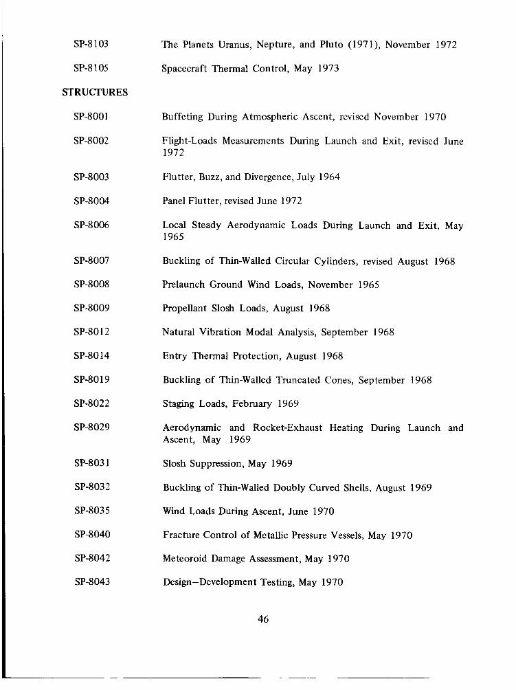
SP-8 1 03
SP-8 105
STRUCTURES
SP-800 1
SP-8002
SP-8003
SP-8004
SP-8 006
SP-8007
SP-8008
SP-8009
SP-80 12
SP-80 14
SP-80 19
SP-8022
SP-8029
SP-803 1
SP-8032
SP-803 5
SP-8040
SP-8042
SP-8043
The Planets Uranus, Nepture, and Pluto (1971), November 1972
Spacecraft Thermal Control, May 1973
Buffeting During Atmospheric Ascent, revised November 1970
Flight-Loads Measurements During Launch and Exit, revised June 1972
Flutter, Buzz, and Divergence, July 1964
Panel Flutter, revised June 1972
Local Steady Aerodynamic Loads During Launch and Exit, May 1965
Buckling of Thin-Walled Circular Cylinders, revised August 1968
Prelaunch Ground Wind Loads, November 1965
Propellant Slosh Loads, August 1968
Natural Vibration Modal Analysis, September 1968
Entry Thermal Protection, August 1968
Buckling of Thin-Walled Truncated Cones, September 1968
Staging Loads, February 1969
Aerodynamic and Rocket-Exhaust Heating During Launch and Ascent, May 1969
Slosh Suppression, May 1969
Buckling of Thin-Walled Doubly Curved Shells, August 1969
Wind Loads During Ascent, June 1970
Fracture Control of Metallic Pressure Vessels, May 1970
Meteoroid Damage Assessment, May 1970
Design-Development Testing, May 1970
46

SP-8044
SP-8045
SP-8046
SP-8050
SP-805 3
SP-8054
SP-8055
SP-8056
SP-8057
SP-8060
SP-806 1
SP-8062
SP-8063
SP-8066
SP-8068
SP-8072
SP-8 07 7
SP-8 07 9
SP-8082
SP-8083
SP-8095
Qualification Testing, May 1970
Acceptance Testing, April 1970
Landing Impact Attenuation for Non-Surface-Planing Landers, April 1970
Structural Vibration Prediction, June 1970
Nuclear and Space Radiation Effects on Materials, June 1970
Space Radiation Protection, June 1970
Prevention of Coupled Structure-Propulsion Instability (Pogo) , October 1970
Fiight Separation Mechanisms, October 1970
Structural Design Criteria Applicable to a Space Shuttle, revised March 1972
Compartment Venting, November 1970
Interaction with Umblicals and Launch Stand, August 1970
Entry Gasdynamic Heating, January 1971
Lubrication, Friction, and Wear, June 197 1
Deployable Aerodynamic Deceleration Systems, June 197 1
Buckling Strength of Structural Plates, June 1971
Acoustic Loads Generated by the Propulsion System, June 1971
Transportation and Handling Loads, September 197 1
Structural Interaction with Control Systems, November 197 1
StressCorrosion Cracking in Metals, August 197 1
Discontinuity in Metallic Pressure Vessels, November 197 1
Preliminary Criteria for the Fracture Control of Space Shuttle Structures, June 1971
47

SP-8099 Combining Ascent Loads, May 1Y72
SP-8 104 Structural Interaction With Transportation and Handling Systems, January 1973
GUIDANCE AND CONTROL
SP-80 15
SP-80 16
SP-80 18
SP-8 024
SP-8026
SP-8027
SP-8028
SP-8033
SP-8034
SP-8036
SP-8047
SP-8058
SP-8059
SP-8065
SP-8070
SP-807 1
SP-8074
SP-8078
Guidance and Navigation for Entry Vehicles, November 1968
Effects of Structural Flexibility on Spacecraft Control Systems, April 1969
Spacecraft Magnetic Torques, March 1969
Spacecraft Gravitational Torques, May 1969
Spacecraft Star Trackers, July 1970
Spacecraft Radiation Torques, October 1969
Entry Vehicle Control, November 1969
Spacecraft Earth Horizon Sensors, December 1969
Spacecraft Mass Expulsion Torques, December 1969
Effects of Structural Flexibility on Launch Vehicle Control Systems. February 1970
Spacecraft Sun Sensors, June 1970
Spacecraft Aerodynamic Torques, January 197 1
Spacecraft Attitude Control During Thrusting Maneuvers, February 197 1
Tubular Spacecraft Booms (Extendible, Reel Stored). February 1971
Spaceborne Digital Computer Systems, March 197 1
Passive Gravity-Gradien t Libration Dampers, February 197 1
Spacecraft Solar Cell Arrays, May 197 1
Spaceborne Electronic Imaging Systems, June 197 1
48

SP-8 0 8 6 Space Vehicle Displays Design Criteria, March 1972
SP-8096 Space Vehicle Gyroscope Sensor Applications, October 1972
SP-8098 Effects of Structural Flexibility on Entry Vehicle Control Systems, Jxne 1972
SP-8 102 Space Vehicle Accelerometer Applications, December 197 2
CHEMICAL PROPULSION
SP-8025 Solid Rocket Motor Metal Cases, April 1970
SP-8039
SP-804 1
3P-8048
SP-805 1
SP-8052
SP-8064
SP-8075
SP-8 07 6
SP-8080
SP-808 1
SP-8087
SP-8090
SP-8 10 1
Solid Rocket Motor Performance Analysis and Prediction, May 197 1
Captive-Fired Testing of Solid Rocket Motors, March 197 1
Liqaid Rocket 5Egir.e Turbspuzp Bearings, Mach 1 9? 1
Solid Rocket Motor Igniters, March 1971
Liquid Rocket Engine Turbopump Inducers, May 197 1
Solid Propellant Selection and Characterization, June 197 1
Solid Propellant Processing Factors irf Rocket Motor Design, October 1971
Solid Propellant Grain Design and Internal Ballistics, March 1972
Liquid Rocket Pressure Regulators, Relief Valves, Check Valves, Burst Disks, and Explosive Valves, March 1973
Liquid Propellant Gas Generators, March 1972
Liquid Rocket Engine FluidCooled Combustion Chambers, April 1972
Liquid Rocket Actuators and Operators, May 1973
Liquid Rocket Engine Turbopump Shafts and Couplings, September 1972
49