NASA Repair or Replacement Combustor Repair NARIoy-A Cracking Investigation Nozzle Repair Background...
154
(_A5|-C_-1351_9) AB_CSd_KE THRUST CHAMBEP _CGFA_ Final 6epoct (Sccketdyne) 167 p HC AO8/E_ A01 CSCL 21H NASA N77-21189 Uncias G3/20 23691 NASA CR-135169 R76-189 / AEROSPIKE THRUST CHAMBER PROGRAM FINAL REPORT by J. Campbell, Jr. and S. M. Cobb ROCKETDYNE DIVISION ROCKWELL I NTERNATI ONAL prepared for NATIONAL AERONAUTICS AriD SPACE ADMINISTRATION NASA Lewls Research Center Contract NAS3-20076 https://ntrs.nasa.gov/search.jsp?R=19770014245 2018-06-09T06:42:51+00:00Z
Transcript of NASA Repair or Replacement Combustor Repair NARIoy-A Cracking Investigation Nozzle Repair Background...

(_A5|-C_-1351_9) AB_CSd_KE THRUST CHAMBEP
_CGFA_ Final 6epoct (Sccketdyne) 167 p HC
AO8/E_ A01 CSCL 21H
NASA
N77-21189
Uncias
G3/20 23691
NASA CR-135169
R76-189
/
AEROSPIKE THRUST CHAMBER PROGRAM
FINAL REPORT
by J. Campbell, Jr. and S. M. Cobb
ROCKETDYNE DIVISION
ROCKWELL I NTERNATI ONAL
prepared for
NATIONAL AERONAUTICS AriD SPACE ADMINISTRATION
NASA Lewls Research Center
Contract NAS3-20076
https://ntrs.nasa.gov/search.jsp?R=19770014245 2018-06-09T06:42:51+00:00Z
I. R©l_t NO. 2. Govem, n*nt Ace.s,on" No.'
CR-13516941 TItl_ l,ld 5ubhtl¢
FINAL REPORT, AEROSPIKE TIIRUST CIIAHBER PROGRAM
?. Authott$1
J. Campbell, Jr. and S. M. Cobb
9. _rf_miny Org_.nizatiun f4_me and Address
Rocketdyne Division of Rockwell International Carp
6633 Canoga Avenue
Canoga Park, California 91304
12. Sponto¢ing A91nc ¥ Name and Address
National Aeronautics and Space Administration
NASA Lewis Research Center
Cleveland, Ohio
TS. Supp_e.'nentary Nole_,
,. o
3. Recipienl'$ Catalog No.
$. Report Date
December 1976
6. Perlormin 90rganizatio."_ Code
8. Performing Orgmizatlon Report hlo.
R76-179
10. Work Unit No.
II. Contract or Grant No.
NAS3-20076
13. Type of Report end Period Coveted
Contractor Report
14. Spo_so, ing Agency Code
Project Hanager, H. G. Price, Jr., ASC Program, NASA Lewis Research
Center, Cleveland, Ohio
Is. Abst,., _\
An existing, but damaged, 25,000-pound thrust, fllghtweight, oxygen/hydrogen
aerospike rocket thrust chamber that was available front a previous Air Force
sponsored program was disassembled and partially repaired. A brief descrip-
tion is presented of the aerospike chamber configuration and of the damage it
had suffered. Techniques for aerospike thrust chamber repair were developed,
and are described, covering repair procedures for lightweight tubular nozzles,
titanium thrust structures, and copper channel combustors. The contract effort
was termlnatcd prior to completion of the repairs and conduct of a planned hot
fire test program when it was found that the copper alloy walls of many of the
thrust chamber's 24 eombustors had been degraded in strength and ductility
during the initial fabrication of the thrust Chamber. The degradation is dis-
cussed and traced to a reaction between oxygen _nd/or oxides diffused Into the
copper alloy during fabrication processes and the hydrogen utilized as a braz-
ing furnace atmosphere during the initial assembly operation on many of thecombustors.
The effects of the H2/O 2 reaction within the copper alloy are described. The
significance relative to the aerospike thrust chamber concept of the repair
techniques developed, and of the !!2/O 2 reaction problem is discussed.
17. Key Words (Suggested by Aulho, i$)l
Aerospike thrust chamber
Hydrogen/oxygen embrt t t lenient
Thrust chamber repair techniques
lg, _cur,ly Class,l. (of th,$ reportl
UNCLASSIFIED
t0. Otlt_;b_t,on Statement
Unclassified
20. _cur,tv Clastd. Iof thtt, I_gel t _1. NO. of Peges
UNCLASSIFIED J 126
• Forsale by Ihe f_Jl,onallechn,c.ll InformMionScfv,ce. Sp,,ngf,eld.V,g,n,a 2215|
_
NASA.C.t6111Rrv t,. ;!
CONTENTS
Introduction .
Program Plan .....
Thrust Chamber Assembly Description
Overall ....
Combustor Segment Design
Design of Thrust Chamber Assembly
Thrust Chamber Damag_
Thrust Chamber Disassen_ly and Repair
Disassembly
Component Repair or Replacement
Combustor Repair
NARIoy-A Cracking Investigation
Nozzle Repair
Background . •
Chamber Support Structure
Backup Rings •
Thrust Cone and Support Struts
Interconnect Components
Discussion of Results . •
Distribution List for Final Report •
13
17
19
19
28
33
49
53
53
53
53
69
I01
i0!
III
iii
Iii
119
125
127
iil
Ir
ILLUSTRATIONS
i,
2.
3.
4.
5.
6.
7.
8.
9.
i0.
ii.
12.
13.
14.
15.
16.
17.
18.
19.
20.
21.
22.
23.
24.
25.
26.
27.
28.
29.
30.
iii kN (25K) O21H 2 Aerospike Engine .....
Segment Combustor Fabrication .....
Photo of Crack in Unit 507R LOX Cover Sheet • •
Section Near Crack in Outer Half of Segment 510
Tube Repair Methods .....
Completed Nozzle Repair • • • • "
Aerospike Nozzle • •
Nozzle Type and Size Comparison
Program Schedule • •
iii kN (25K) Aerospike Demonstrator Thrust Chamber Assembly
iii kN (25K) Aerospike Demonstrator Thrust Chamber Assembly
Thrust Chamber Assembly Procedure .....
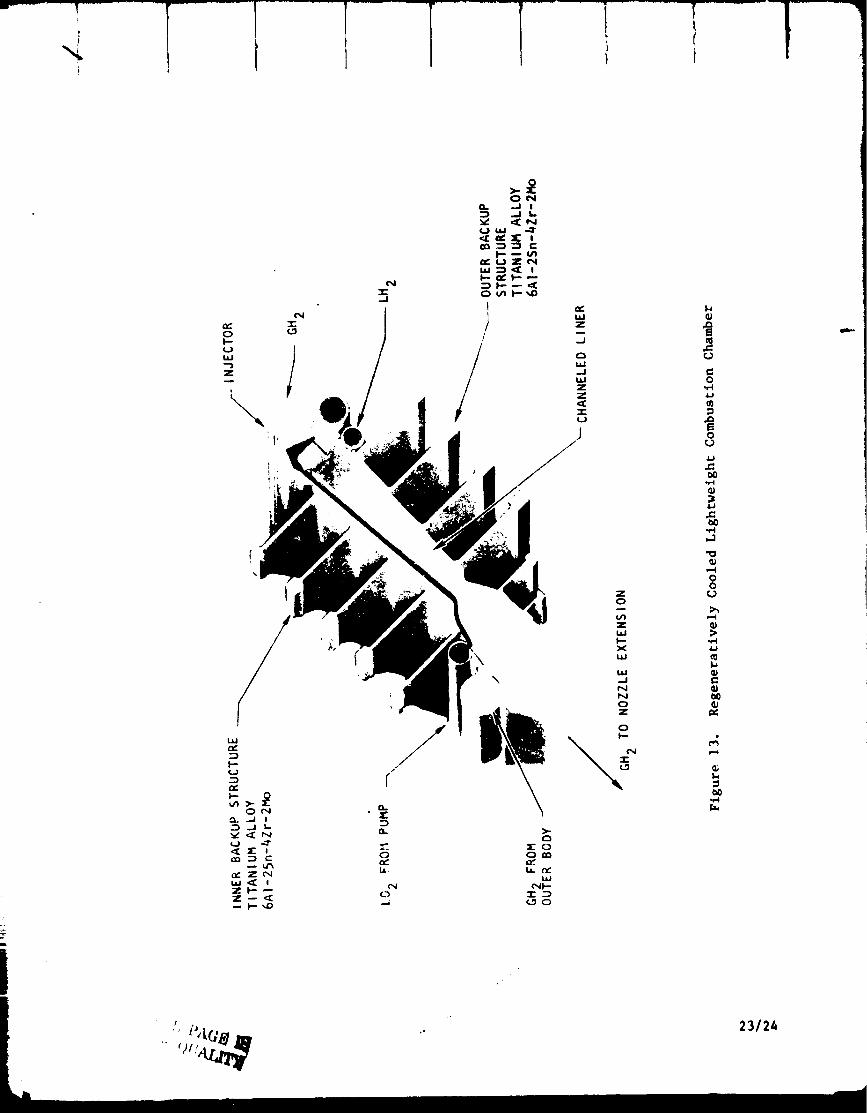
Regeneratively Cooled Lightweight Combustion Chamber • . •
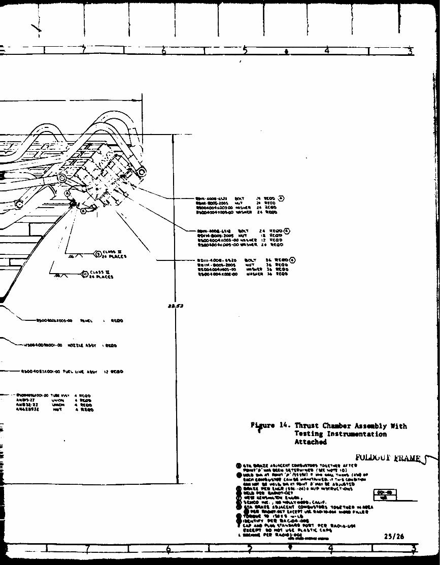
Thrust Chamber Assembly With Testing Instrumentation Attached
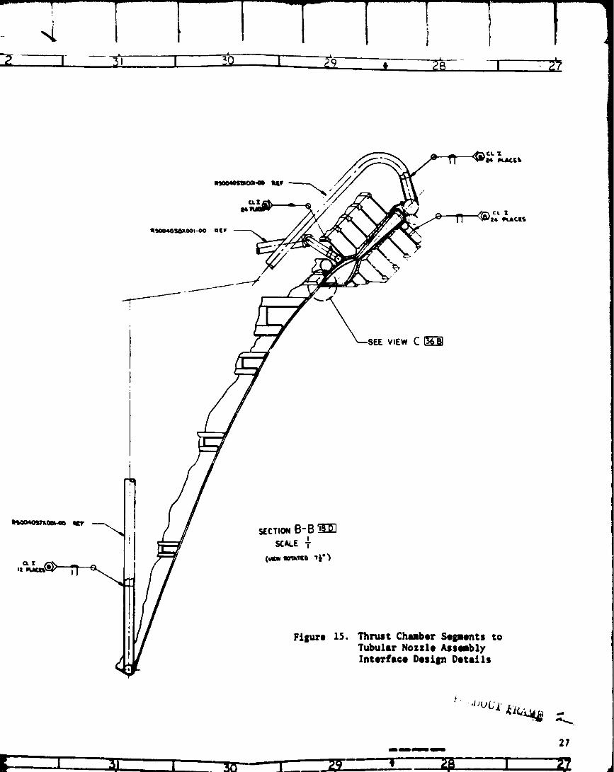
Thrust Chamber Segments to Tubular Nozzle Assembly Interface
Design Details ....
Thcust Chamber Cooling Circuit
Double Panel Segment Design •
Double-Panel Cooling Concept •
Combustor Segment Stacking • '
Inner Back-Up Structure • • .
Outer Back-Up Structure •
Tapered Nozzle Extension Formed Contour Tube
Nozzle Base C]osure Assembly ......
Thrust Chamber Assembly .... ' "
Thrust Chamber Assembly After Fire • . • '
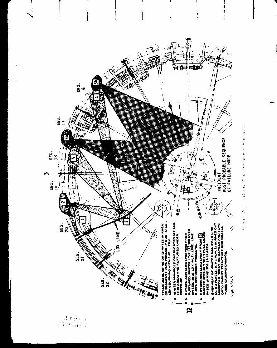
Failure Mode Sequence Schematic .......
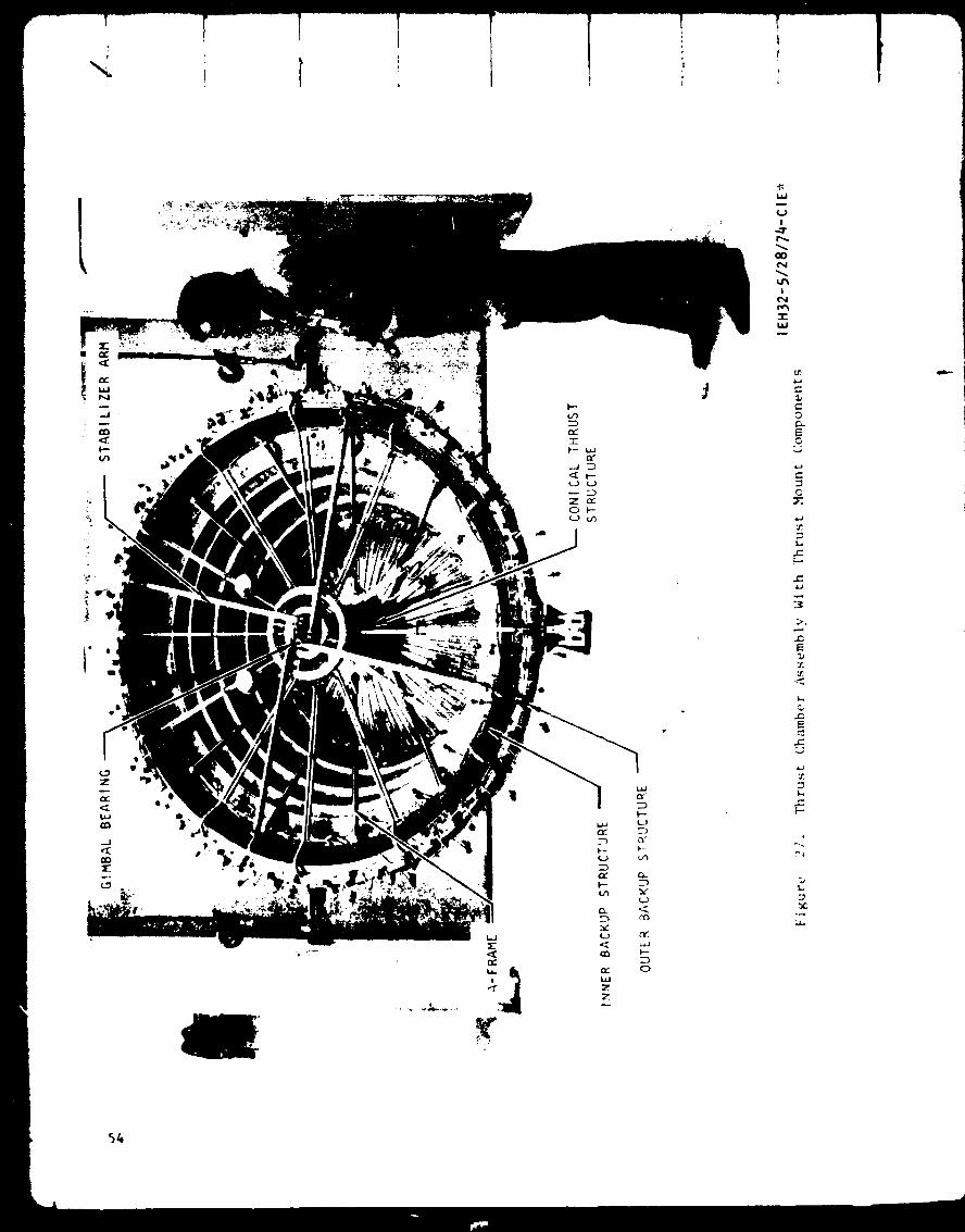
Thrust Chamber Assembly With Thrust Mount Components
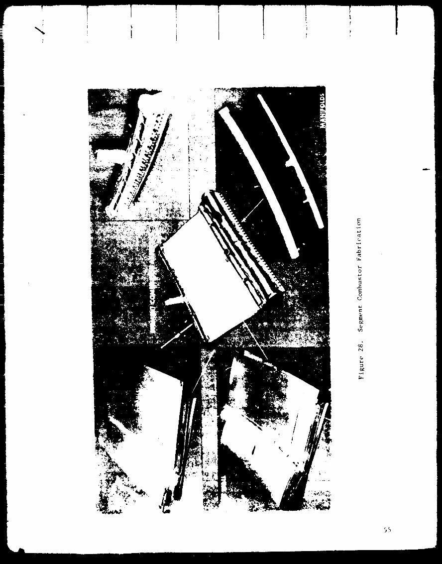
Segment Combustor Fabrication ....
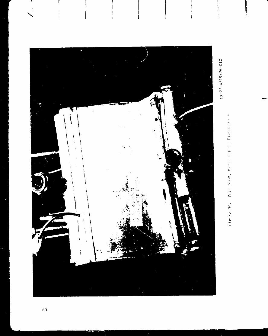
Unit 507R, Braze Repair Preparation • • ' "
Unit 51OR, Braze Repair Preparation ......
2
4
5
7
I0
ii
14
15
18
20
21
22
23
25
27
29
31
32
35
37
39
42
43
45
50
51
54
55
59
6O
., j.;t)E,,;G L A(,L BI,ANK NOT FILMI_ v
31. Unit 507R, Braze Repaired ....
32. Photo of Crack in Unlt 507R LOX Cover Sheet . . .
33. Unit 51OR, Braze Repaired .....
34. Crack Repair Concept ....
35. Electrodeposited Copper Apparatus . .
36. Electrodeposited Copper . • •
37.
38.
39.
40.
41.
42.
43.
44.
45.
46.
47.
48.
49.
50.
5t.
52.
53.
Cover Sheet in Outer Half of Segment 510 Viewed From Cover
Sheet Side ...........
Section Through Crack in Outer Cover Sheet of Segment 510
Section Near Crack in Outer Half of Segment 510 . . •
Test Specimen From a Gold-Plated Cover Sheet Subjected to One Braze
Cycle in H2 After Thorough Surface Cleaning
Section From Outer Half of Segment 514 Showing Severe 02-H 2
Reaction .......
Section From Outer Half of Segment 516, Showing Slight 02-H 2
Reaction .....
Section From Outer Half of Segment 516, Showing Slight 02-112
Reaction .....
Test Specimen From NARIoy-A Cover Sheet, Furnace Brazed in Argon
Section From Inner Half of Segment 510R • .
Segment Assembly Sequence ......
Test Specimen From NARIo.,-A Cover Sheet, Furnace Brazed in Argon,
Surface Oxidized With Torch, Reheated |u Argon Furnace to 871C
(1600 F), Then H 2 at 871C (1600 F) .....
Test Specimen From NARIoy-A Cover Sheet, Furnace Brazed in Argon,
Surface Oxidized With Torch Reheated in Argon Furnace to 871 C
(1600 F), Then H 2 at 871C (1600 F) .......
Oxidation/Diffusion, H2-O 2 Reaction Experiment .....
Section From Outer Half of Segment 504 ....
Section From Outer Half of Segment 507 ......
Section From Center of Outer Half of Segment 510 ....
Section From Outer Half of Segment 512, Showing Severe 02-H 2
Reaction ..................
61
62
63
65
66
68
70
71
72
76
77
79
80
81
82
83
85
86
88
9]
92
93
94
vl
JJ
54.
55.
56.
57.
58.
59.
60.
61.
62.
63.
64.
65.
66.
67.
68.
69.
70.
71.
72.
73.
Section From Outer Half of Segment 512, Showing Severe O2-H 2
Reaction • • • • •
Section From Outer Half of Segment 514 Showing Severe O2H 2
Reaction
Section From Outer Half of Segment 518
Section From Outer Half of Segment 522
Sections From Aft Edge of Outer Cover Sheet on Segment 523
Section From Outer Half of Segment 525
Typical Nozzle Tube Damage
Location of Tube Damage
Tube Repair Methods
Improper Saddle Patch Condition
Completed Nozzle Repair
Air Flow Measurement to Detect Nozzle Tube Flow Restrictions
Typical Results -- Flow Check of Repaired Nozzle Tubes, Unit 526
Lightweight Inner Backup Structure
Completed Inner Backup Structure Ring
Inner Surface Damage -- Outer Backup Structure
Bolt Hole Damage -- Outer Backup Structure •
Outer Backup Structure
Oxidizer Manifold Inlet Assembly
Fuel Hanlfold inlet Assembly
95
96
97
98
99
IO0
102
103
104
I05
106
108
109
113
115
116
117
I18
121
123
vii

TABLES
le
2.
o
4.
5.
6.
7.
8.
9.
Combustor Body-Injector Usagr .... ....
Aerospike Thrust Chamber Repair Summary of Furnace Cycle llistory
on Segments ......
Design Conditions . • • "
Thrust Chamber Heat Transfer • • • • •
Combustor Design Criteria ......
Combustor Body-Injector Usage . •
Metallographic Investigation of Segments
NARIoy-A Processing and Quality Control
Aerospike Thrust Chamber Repair Summary of Furnace Cycle History
on Segments • •
8
19
30
04
56
73
75
89
ix

SUHttAR¥
The iii kN (25K) aerospike thrust chamber project, Contract No. NAS3-20076,
was conceived as a means of carrying out an aerospike thrust chamber feasi-
bility demonstration project. A similar project had been previously funded
under Air Force auspices. The Air Force contract, No. F04611-67-C-0016,
resulted in the design, fabrication, and initial testin_ of a IIi kN
(25,000-pound) thrust hydrogen/oxygen aerospike thrust chamber for possible
space tug application. The Air Force contract was terminated in 1975 after
the chamber was extensively damaged in a test stand fire. The NASA retained
an interest in the possible application of the aerospike thrust chamber
concept to space propulsion and contracted with Rocketdyne under Contract
NAS3-20076 for the purpose of repairing the existing iii kN (25K) aero-
spike thrust chamber and conducting altitude firings to determine the
chamber's performance, cooling capability, and structural integrity.
While the planned program included both the repair of the thrust chamber
and a hot-fire testing series, all effort actually expended on th_ program
was confined to the repair of the thrust chamber components. This condi-
tion came about because a fundamental problem with the material processes
utilized in the initial fabrication of the combustors was uncovered during
the repair effort. Thus, the content of this report, and of this summary,
covers the repair and fabrication procedures developed to permit repair
of aerospike chambers.
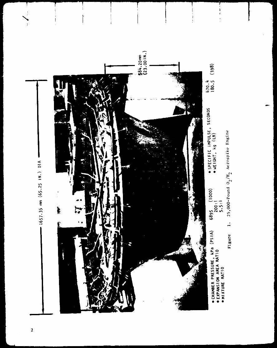
The Iii kN (25K) aerospike thrust chamber assembly consisted of 24 regen-
eratively cooled combustor segments arranged around the periphery of a
regeneratively cooled nozzle and base closure assembly so as to discharge
their gases against the nozzle. A view of the thrust chamber assembly is
shown in Fig. l together with a summary of the thrust chamber design a,d
operating parameters.
The damage that was incurred during thrust chamber test 74-005 on the Air
Force contract was assessed by disassembly and cleaning of those components
that had been assembled with fasteners, ire., the ducting and unboltable
support structure. An assessment of the damage indicated that it would
be necessary to replace five of the combustors, the inner backup support
ring, the ignition manifolding and propellant feedlines, and some of the
thrust chamber support structure. Additionally, it would be necessary to
repair the outer titanium backup ring, the thrust cone, and approximately
30% of the nozzle tubes.
The nature of the aerospike thrust chamber assembly is such that it is
possible to effect repairs by replacing damaged components _ith functional
components, i.e., unbolt or cut out the damaged component and replace it
with a good one. The thrust chamber combustors, while brazed and welded
assemblies, also were Judged to be repairable in this manner. As there
were a number of combustors available that had some usable parts, a plan
was devised for combustor replacement which involved cannibalization of
portions of the existing spare combustors so as to utilize them in combi-nation with new components to produce viable combustors suitable for welding
,4
e_
r,
014¢J
t4::X::
0
tl
0
I000
1,4
el)

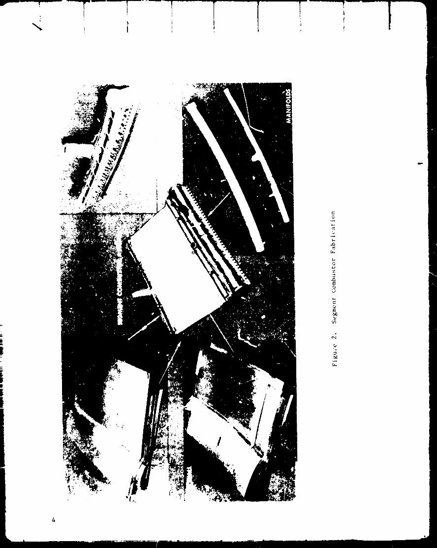
in-place on the existing thrust chamber assembly. 1%Is is believed to be
the first time that dissection and reassembly of such welded combustors
was attempted. It was made possible by the unique fabrication scheme of
the !ii kN (25K) aerosplke chambers which is illustrated in Fig. 2. Table
1 lists the five rebuilt combustors from which replacements for the assem-
bly were to be obtained, and indicates the scheme for utilization of exlst-
ing parts.
TABLE i. COMBUSTOR BODY-INJECTOR USAGE
Combustor SegmentIdentification
Unit No.
507R
51OR
509R
515R
535(N)
InjectorUnit No.
506
518
New
New
New
Inner Liner
Unit No.
507
510
New liner, coolant
panel, cover sheet,and end olates
Outlet Liner
Unit No.
507
510
509
515
New liner,cover sheet,
and end plate
R = rebuiltN = new
Three of the rebuilt combustors, units 509R, 515R, and 535, were dependent
upon new inner liners for completion. %he rework of the existing details
and the fabrication of the new liner assemblies for these combustors was
satisfactorily carried through, but was belted in the second quarter of
the program to concentrate efforts on completing combustor units 507R and
51OR.
Combustor units 507R and 510R were planned to utilize existing inner and
outer liners, and had been partially completed under the sponsorship of
the previous Air Force contract. Both of these combustors encountered
problems with cover-sheet cracking during their final assembly operation.
A photo of a typical cover-sheet crack Is shown in Flg. 3 • The cracking
was at first attributed _o the unusual strains associated wlth the assem-
bly operations, and repairs were effected by both furnace braze and tung-
sten inert gas brazing wlth Nforo braze alloy. These repair efforts were
generally unsuccessful in that further cracking of the material occurred,
either in the heat-affected zone of the TIG-brazed areas, or during the
cryogenic shock cycling employed for evaluation of repair effectiveness.
I
I
eJ_

m
F
Figure 3. Photo of Crack in UnLt 507R LOX
Cover Sheet (IOX Magnification)
It becm_e evident after repeated attempts at repair of the cover-sheet
cracking experienced on units 507R and 51OR, that a condition existed that
was not consistent with the ductility normally displayed by NARIoy-A. In-
vestigations were undertaken to find the reasons fol the nontypical crack-
ing, and also to find some way to bring units 507R and 510R to successful
completion.
A repair concept was developed for the NARIoy-A cover-sheet cracks of units
507R and 510Rwhich involved dishing out the cracked areas and electro-
depositing copper into the groove. Both cell plating, in which a small
electroplating cell is clamped to the side of the part to be repaired rather
than submerging the whole part in plating solution, and tank plating were
successfully employed on the crack areas of the cover-sheets that were
accessible. However, on completion of the repairs, and the conduct of cry-
ogenic shock testing and hydrostatic pressure testing, it was found that
additional cracking had occurred. On the basis of this experience, it was
determined that neither 507R nor 510R was suitable for assembly to the
thrust chamber.
The NARIoy-A cracking encountered on units 507R and 510R was so nontypical
that it engendered a metallurgical and historical investigation, concurrent
with the repair effort on 507R and 51OR, to understand the problem and to
assess its implications for all the combustors. Methods of removing samples
from existing combustors were developed which permitted metallurgical exam-c_ the removed
ination of the NARIoy material and, if necessary, replacement _
sample so as to be able to fire the combustor. Microscopic examination of
these samples indicated that the fundamental cause of the cracking of 507R
and 510R was that the NARloy material properties had been degraded by the
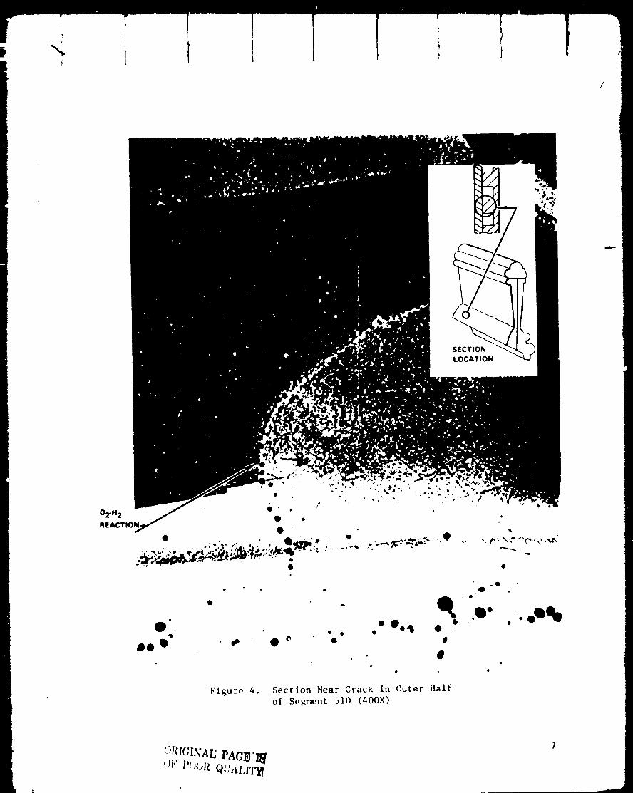
reaction of hydrogen with previously dissolved oxygen. Figure 4 is a
photomicrograph of material removed from unit 510R. It shows the voids
along the grain boundaries that result when steam is formed. The sourqe
of hydrogen was readily ascribed to the hydrogen atmosphere furnace brazing
that had been utilized during the initial fabrication of the combustors.
An investigation was conducted as to the source of oxygen and it was deter-
mined that the most probable source was oxidation of the inner surfaces of
the liners and cover-sheets during the initial fabrication (i.e., in 1974).
This inner surface oxidation had apparently occurred despite the utiliza-
tion of inert atmospheres during these operations and despite the imposi-
tion of well-developed disciplines for the maintenance of cleanliness.
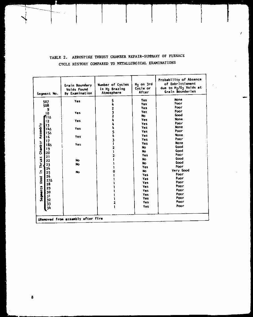
The res_llts of the metallurgical examination of all combustors sampled ale
presented in Table 2, which indicates a correlation between the presence
of embrittled NARIoy-A and the conduct of final brazing cycles in a hydro-
gen atmosphere. On the basis of the data displayed in Table 2, the con-
clusion appears inescapable that a large majority of the combustors have
been affected by the hydrogen/oxygen phenomenon during their initial fabri-
cation (prior to the start of this contract), and will display substant_'ally
reduced ductility under conditions of thermal strain. As it had been demon-
strated during the repair procedures on 507R and 510R that the thermal
strains involved in cryogenic testing did result in cracking of the embrit-
tied NARIoy, and as the test program planned for the thrust chamber assembly
6
: q
i 1
O . • •
De 0 • ,o 4t _" •
.e
O •
.w . oQee• ee4 _ •
0
o
Figure 4. Section Near Crack in Outer Half
of Segment 510 (400X)
ORI(;INAE PAG_I_
,)i'" t_()()R QUAI,ITy I
t
TABLE 2. AEROSPIKE THRUST CHAHBER REPAIR-SUI_ARY OF FURNACE
CYCLE HISTORY COMPARED TO HETALLURGICAL EXAHINATIOHS
Segment No.
507508
9!0
'12>" 13
14Aw 154
1617184
2021
22_,23
24c 25
26
27_2829
3o323334
k
Grain BoundaryVoids Found
By Examinat;on
Yes
Yes
YesI
Yes
Yes
Yes
NoNo
No
liRemoved from assembly after fire
Number of Cyclesin H2 BrazingAtmosphere
54232444543I2I2II]0I1IIIII2I
H2 on 3rdCycle or
After
YesYesYesYesNoYesYesYesYesYesYesYesNoNoYesNoNoYesNoYesYesYesYesYesYesYesYesYes
Probability of Absenceof Embrittlement
due to H2/0 2 Voids atGrain Boundaries
None
PoorPoorPoorGoodNonePoorNonePoorNonePoorNoneGoodGoodPoorGoodGoodPoor
Very GoodPoorPoorPoorPoorPoorPoorPoorPoorPoor
did involve numerous strain cycles, it was concluded that the majority of
combustors available for the assembly were not sufficiently reliable to
permit their utilization in the firing program.
During the test stand fire which terminated the Air Force program, the
nozzle had suffered localized overheating on its interior portions (i.e.,the "cold" side), because it was sprayed with molten titanium from the
burning inner combustor support ring. Repairs to this type of tubular
nozzle had not previously been attempted on the scale represented in this
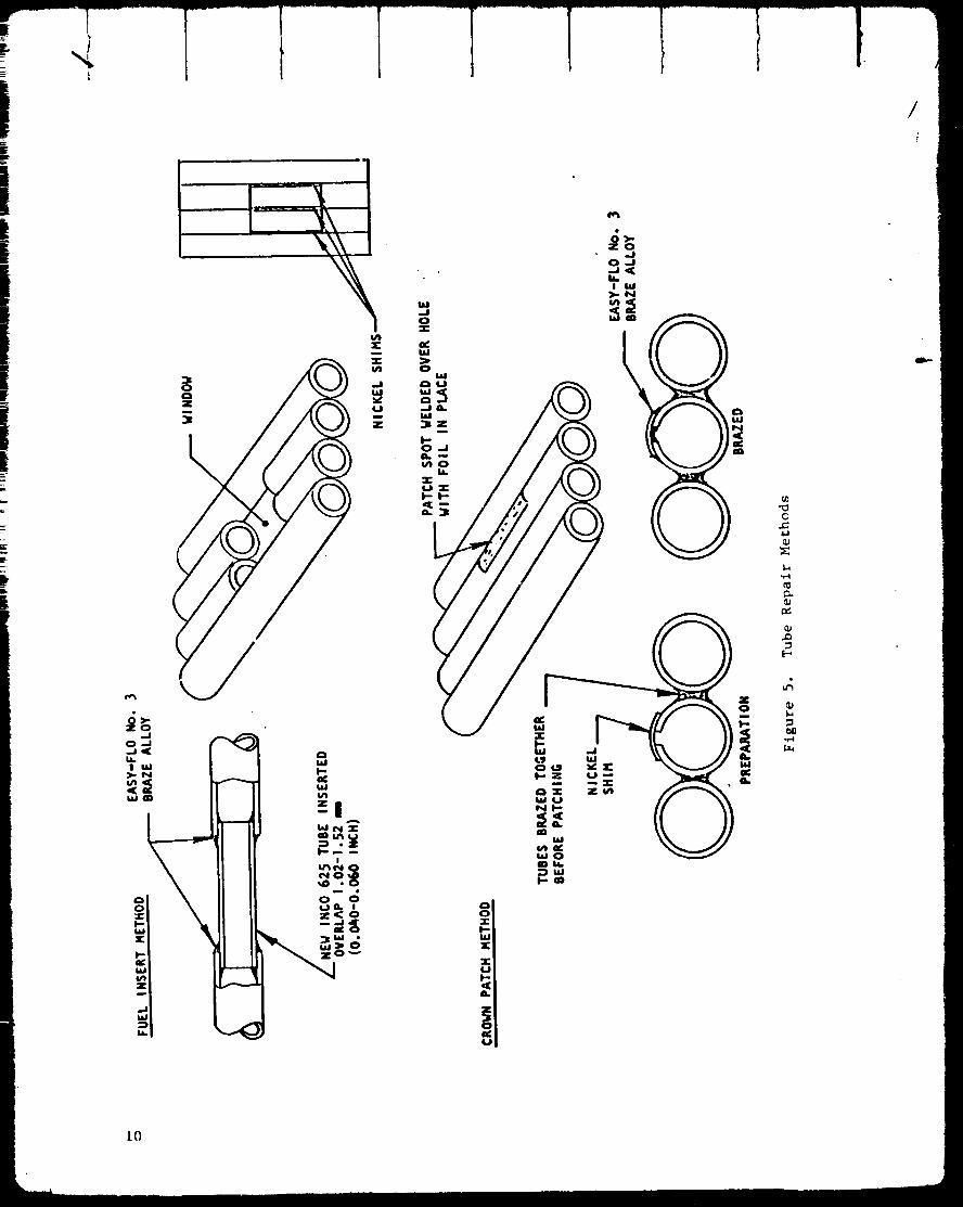
instance. Because ef a general need for developing the technology for
repairing complex lightweight tubular nozzles, a company-sponsored tech-
nology program way undertaken which utilized the 111 kN (25K) aerospikenozzle for development purposes. Two basic methods of repair were devel-
oped, the saddle-patch repair and tile inserted tube repair as defined in
Fig. 5. When properly applied, these two methods sufficed to repair
all of the damage that had been incurred by the 111 kN (25K) aerospikenozzle.
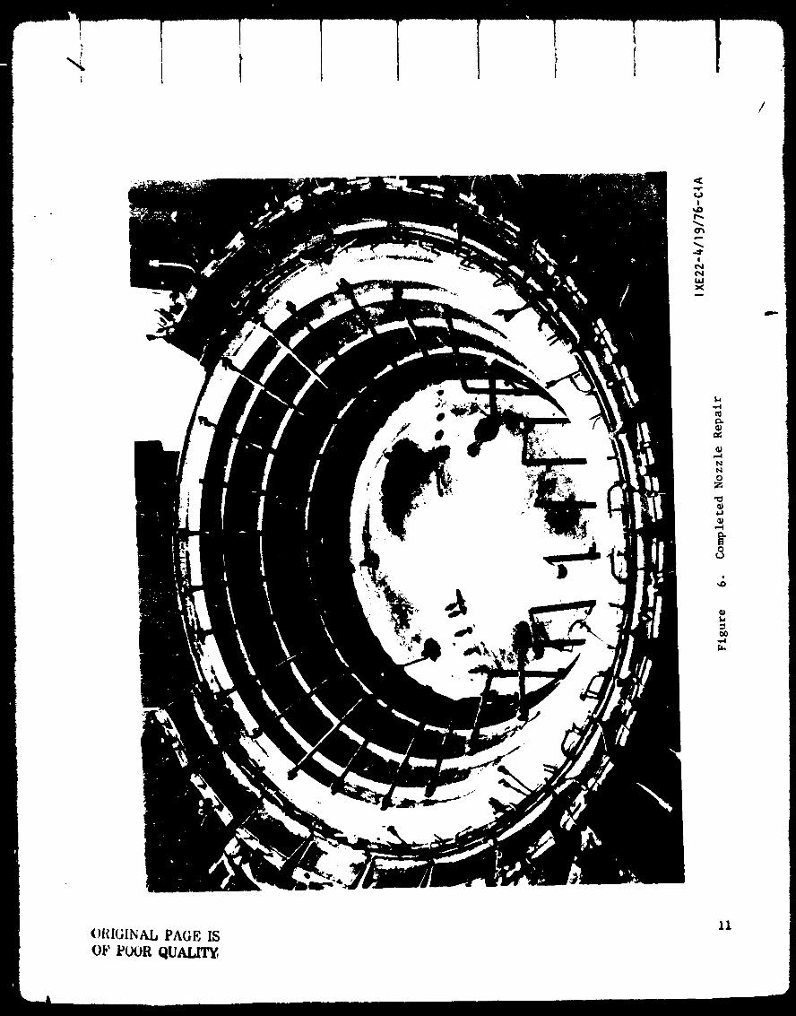
A photograph of the repaired nozzle is shown in Fig. 6. A total of
1,053 saddle patches was applied together with 155 tube insert patches,
the tube inserts being al_plied in 18 different window locations. The noz-
zle repair effort was successfully concluded during the second quarter of
this program with every expectation that the repairs would have proved
adequate for tile scheduled hot-firing program.
The chamber support structure of the aerospike thrust chamber includestwo titanium rings, between which the 24 combustors are sandwiched. The
rings accept the thrust generated by the combustors and nozzle and trans-
mit that thrust to a central gimbal bearing through angled struts and a
central cone. The repair and refurbishment effort of the subject contract
included the redesign of the inner titanium support ring to a more easily
fabricated configuration than the original ring, and the completion of its
fabrication. Additionally, a repair procedure was devised for the more
moderately damaged outer titanium backup ring and checked out by prepara-tion of weld samples in the s_lme configuration. Section examination and
tensih, tests indicated that the welded-in section would be sufficiently
strong for the service, but all fabrication effort was stopped prior to
the acttDal repnir of the, outer backup ring. The thrust cone and support
struts were also rl,workt,d during the active portion of the repair effortand had been largely completed by the time fabrication effort wastermi n;_t ed.
Several positive results were obtained during the disassembly and repairproct,dures:
I. I'he tubular nozzle repnir eff_rt brought out that large-scale
repairs on lightw_,ight tubular nozzles are feasible.
2. The structure repairs indicate that it is feasible to repair such
complex structures aa the outer titanium backup ring.
!
_D
c_
_J
Em_
w_
_D
aDim
10
i
/
!_0
!cM
t_Xm
I-
t_
Nt_0Z
,,_
0
ORIGINAL PAGE IS
0_' POVR QUALIT_
11

. The work conducted with combustor dissection and reassembly bears
out the basic validity of the concept of the repair of such com-
plex copper channel cooling structures by the method of excis-
ing the damaged areas and brazing properly configured replacements
in _belr place.
The basic success of these repair techniques must be considered a positive
factor in future evaluations of the aerospike thrust chamber concept.
Aerospike configurations tend to be relatively expensive and the concept
is favored by the possibility of repair as opposed to replacement of suchchambers when the almost inevitable damage which occurs during development
programs is suffered.
In assessing the overall results of the program, one must keep in mind that
the hydrogen/oxygen reaction problem encountered with the NARIoy-A com-
bustor material does not have any special significance for the aerosplke
thrust chamber concept. Aerosplke thrust chambers are fabricated of the
same materlals as bell thrust chambers. The problem was a materials pro-
cessing problem, not an aerospike problem. The program did have several
positive results for the aerosplke concept although it was not posslble to
carry it through to the hot-firlng phase. On balance, the aerospike must
still be regarded as a contender for length-llmlted, space propulslon
appllcation. The developmental programs prevlously conducted have demon-
strated the concept's performance and length advantages. The previous
Air Force program demonstrated that an aerospike thrust chamber roughly
20% of the length of an equlvalent'bell chamber could be designed and fab-
ricated to a competitive weight, and the present NASA contract demon-
strated that maintenance and repair procedures will be available for
aerospike thrust chambers that will permit cost-effective repairs to theirassemblies.
Jb.
12

INTRODUCTION
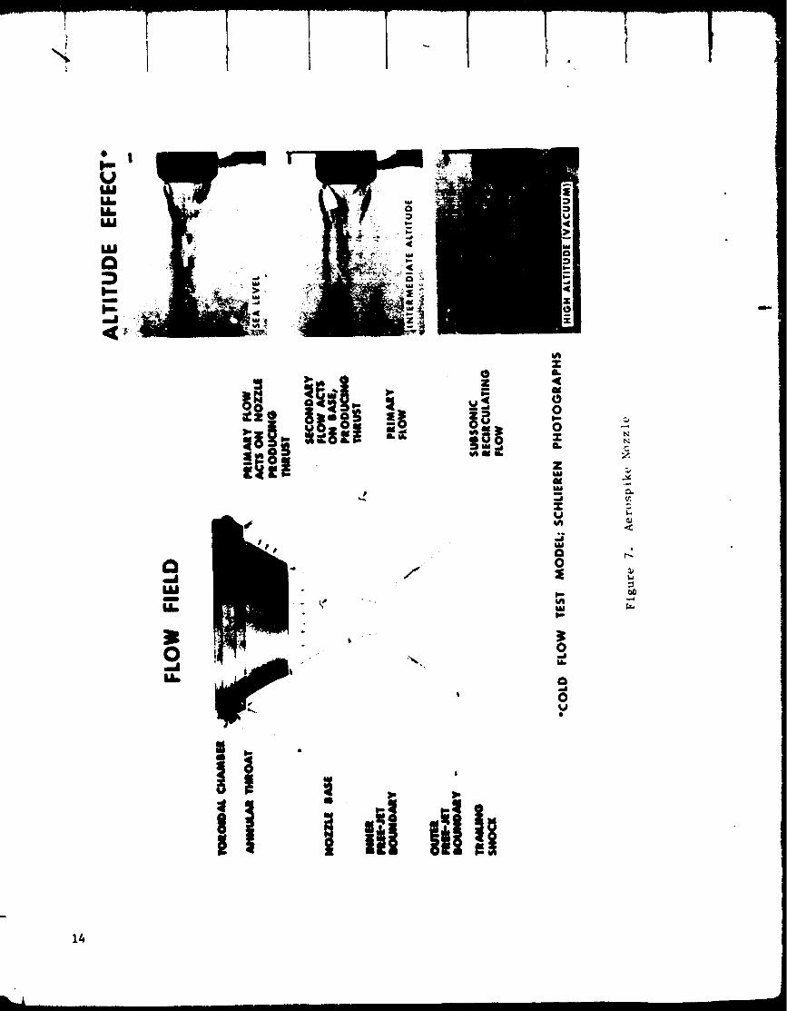
The liquid fuel aerospike rocket engine concept has been under developmentfor approximately 15 years. Its thrust chamber configuration consists ofa truncated annular spike nozzle (radial in-flow type), which is providedwith a number of discrete combustion chambers arranged around the peri-phery of the nozzle so as to discharge their gases along the nozzle sur-face. A diagram illustrating the aerospike thrust chamber concept ispresented in Fig. 7.
The aerospike thrust chamber concept has several advantages relative tomore conventional nozzles. It automatically provides "altitude compensa-tion," and thus may increase the overall impulse supplied in a boosterapplication. It may be arranged to utilize a larger portion of the boat-tail area than a multiple engine conventional installation. Developmenthas demonstrated that it is feasible to truncate a spike nozzle severely,and by utilizing a small amount of secondary flow Introduced into the noz_
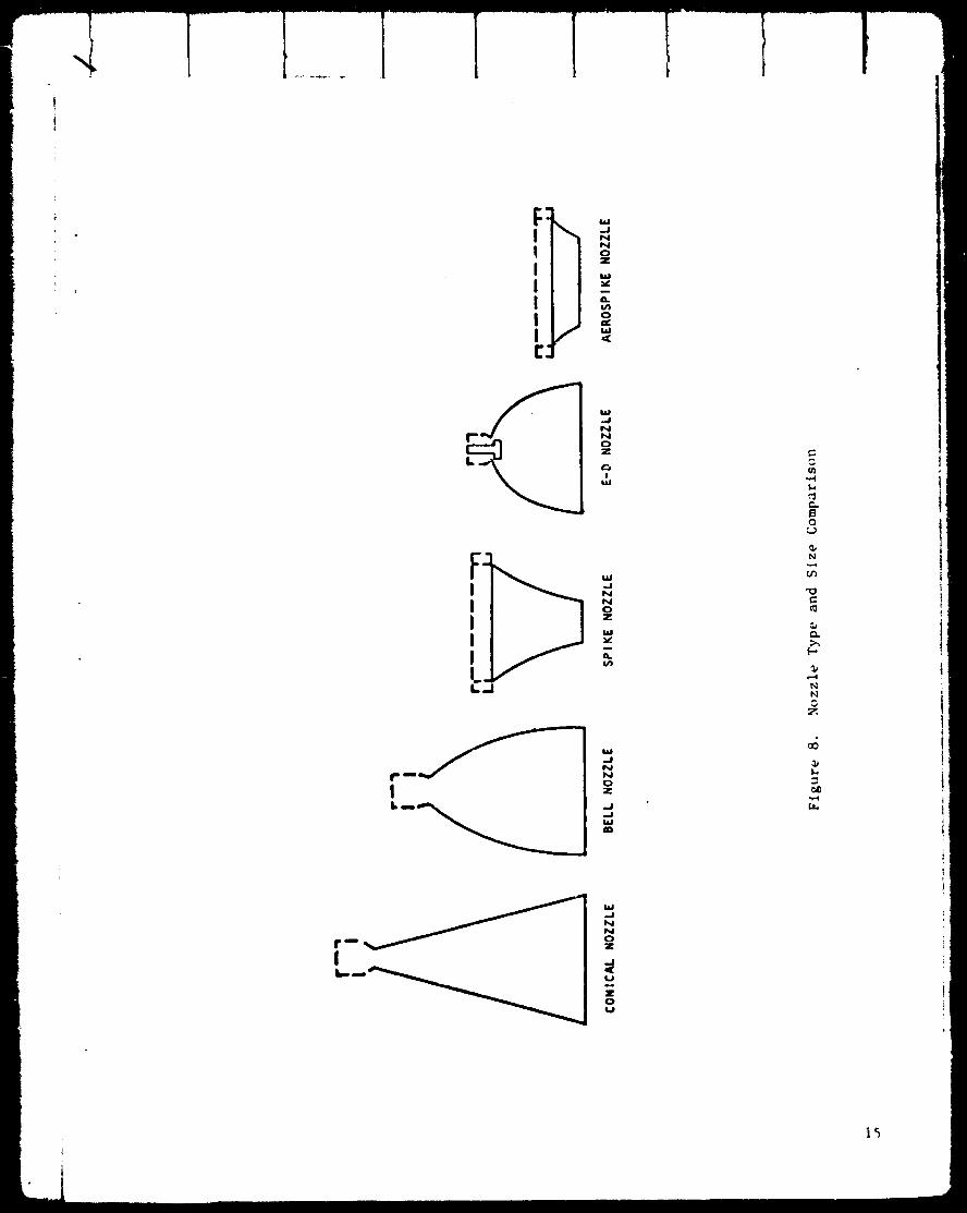
zle base region, to retain excellent nozzle Cf efficiency. This attributeof the aerospike rocket engine has led to its consideration for thosespace propulsion applications in which engine length is especially signi-ficant. A comparison of the thrust chamber lengths of several differenttypes of rocket thrust chamber is presented in Fig. 8, indicating thatthe aerospike thrust chamber can be on the order of 20% of the length of
a bell nozzle of equivalent expansion ratio.
In 1970, a design and development project was undertaken at Rocketdyne todesign, fabricate, and test a 111 kN (25,000-pound) thrust hydrogen/oxygen aerosptke thrust chamber under Air Force Contract No. FO4611-67-C-0116. The objective of this program was to demonstrate, through thefabrication and testing of a flightwetght thrust chamber, that the aero-spike engine concept was competitive in both weight and performance toconventional bell nozzle-type engines. A thrust chamber with a nozzlearea ratio of 200:1, and of competitive weight, was designed, fabricated,installed in the test stand and fired. However, during the first main-stage test, a propellant line leaked, and caused a fire that severelydamaged'the test hardware. A posttest examination of the hardware indi-cated that the thrust chamber was repairable and, under Air Force instruc-tion, the resources remaining in the contract were utilized to begin therepairs to the thrust chamber. The Air Force contract was concluded on31 December 1975. All residual hardware and tooling from the Air Force
program were made available to the NASA. The results of the Air Forceprogram are summarized in .the Final Repot: (Ref. 1) and in the MaterialsResearch and Development Report (Ref. 2).
1. AFRPL-TR-76-05, O2/H 2 Advanced Manuevertng Propulsion Technology Pro-gram, Final Report, Rocketdyne Division, Rockwell international,Febraury 1976.
2. AFRPL-TR-76-06, O2/H 2 Advanced Maneuvering Propulsion Technology Pro-gram 2 Materials Research and De'v_lopment Report, Rocketdyne btvtsion,Rockwell International, February 1976.
J3
O
p.UI&l
u_W
a
p-I
I--
a
I&lg
30
!§|m.- ""
/
f
T
00
0
zW
m
TU
0
0
0
0._J
0_J
N
C
I i,Ii Ii!16
o
o
IIS °I..,J_I..I
0Z
,.J,.J
..,-I
¢,.
Q
N
N
e_
f-.
NN
Z
I,d
U
IE0LJ

//
The NASA retained an interest in tile aerospike engine concept because of
its possible application to the main propulsion system of the full capa-city space tug. The principal aerospike engine feature of interest was
its very short length which, in application to the tug, would result in a
shorter stage and provide more space for payload. The Air Force programhad shown that the application of advanced fabrication techniques and
materials to the aerospike engine made it possible to fabricate a thrustchamber that was consistent in weight with a high-performance-type engine.
However, the program had been concluded short of demonstrating the per-
fot_ance and the structural integrity of the complete flightweight
assembly.
Under these circumstances, the NASA contracted with Rocketdyne under
Contract No. NAS3-20076 for the purpose of repairing the existing 111 kN
(25K) aerospike thrust chamber and conducting altitude firings to deter-
mine its performance, cooling capability, and .qtructural integrity. Itis th_ effort on Contract NA53-20076 that is discussed in this r_.port.
The planned program includt, d thrt_.e techniual tasks: (1) thrust chambtr
disassembly and repair of components, (2) thrust chamber reassembly, and(3) thrust chamber hot-fire testing. All effort actually expended on the
program was confined to Task l, i.e., disassembly of the thrust chamber
and repair of its components. This condition came about because a funda-
mental problem with the material proct, ssing utilized in tht, fabricationof the combu._tors was uncovered during the repair effort.
This report is thus concerned with a dL, scription uf the rather uniqu_
repair and fabrication procedures developed in connection with the acre-
spike chamber repair. The material condition which rest, lted in the pro-
gram's termination is also discussed.
The principal measurements and calculations of tt_is contract were conductedin the customary United States system of units, as w,+re the calculat ions
and measurements of tile pr_,ceding _ir Force Contract No. FO4611-67-(:-Ol16.
The SI _vstem ,*f ,nits is used in tile, text al"ld tablvs of this ri, port, and
the customary tinited St;+tt,s units given parenthetically following the SI
,mits. However° in the intt.r_._Iq of t, conomv, the dimensions of those
_.xi._ting drawing._ which ar_, includ,'d in this rt.port have not been convertt'dt,+ S1 units.
16
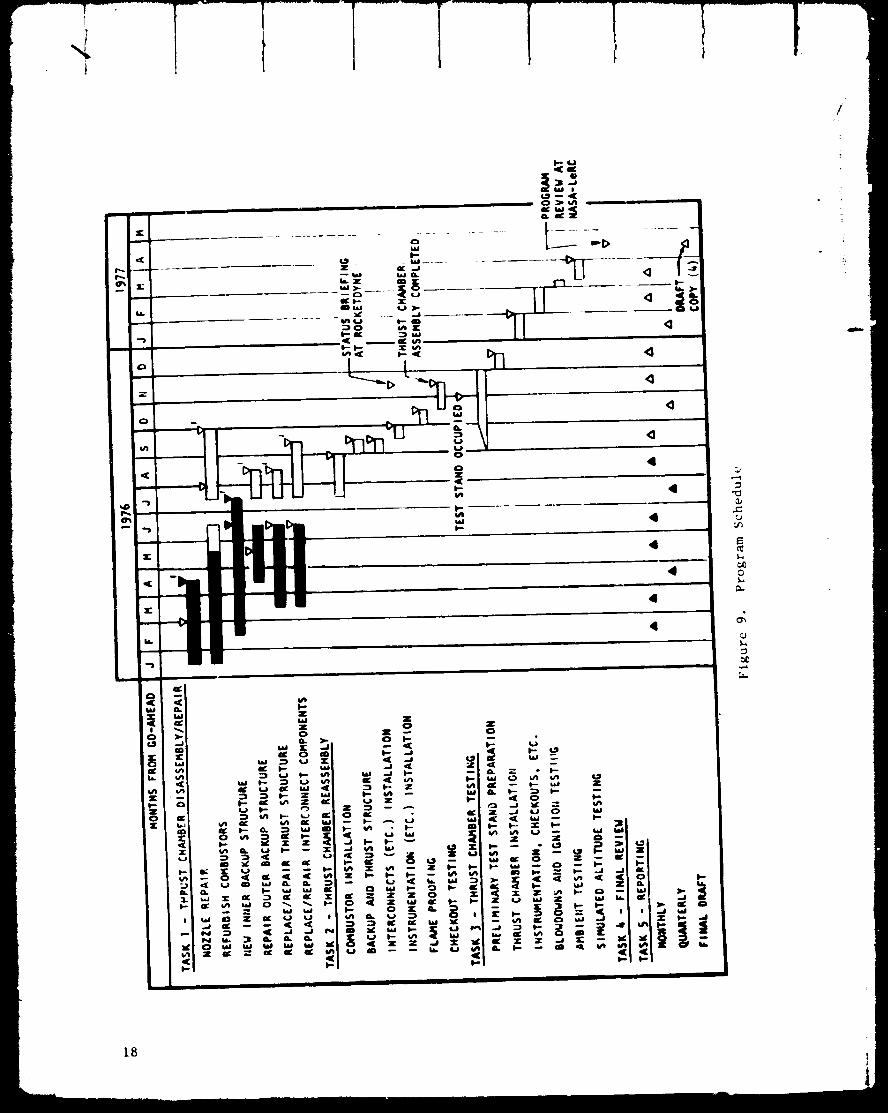
PR_RAHP_N
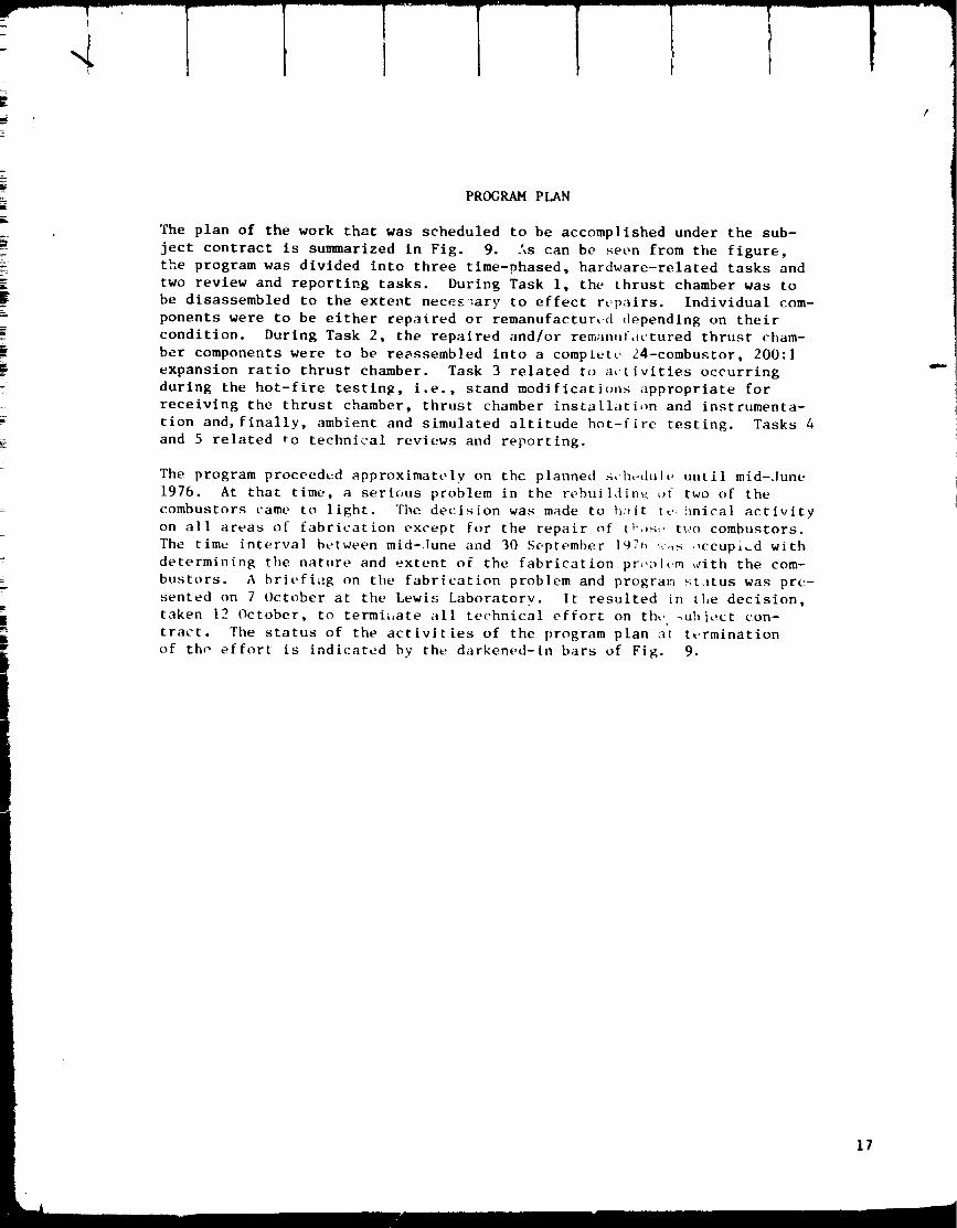
The plan of the work that was scheduled to be accomplished under the sub-
ject contract is summarized in Fig. 9. As can be seen from the figure,
tI_e program was divided into three time-phased, hardware-related tasks and
two review and reporting tasks. During Task i, the thrust chamber was to
be disassembled to the extent necee-_ary to effect rt,pairs. Individual com-
ponents were to be either repaired or remanufacturtJd depending on their
condition. During Task 2, the repaired and/or rema,uf_,ctured thrust cham-
ber components were to be reassembled into a complete. 24-combustor, 200:1
expansion ratio thrust chamber. Task 3 related to activities occurring
during the hot-fire testing, i.e., stand modificatic,ns appropriate for
receiving the thrust chamber, thrust chamber installation and instrumenta-
tion and, finally, ambient and simulated altitude hot-fire testing. Tasks 4
and 5 related to technical reviews and reporting.
The program proceedcd approximately on the planned _,h,-dult* until mid-June
1976. At that time, a serious problem in tile rebuil,lin_, of two of the
combustors came to light. Tbe decision was made to h_It it,,hnica] activity
on all areas of fabrication except for the repair of th,,_,, tx,,o combustors.
The time interval between mid-.lune and 30 September I_7_ ,:.,s ,ccup,_d with
determining the natLlre and extent of the fabrication pr_,:_l_rq _¢ith the com-
bustors. A briefi_g on the fabrication problem and program _tatus was pre-
sented on 7 October at the Lewis Laboratory. It resulted in tl,e decision,
taken 12 October, to termly,ate all technical effort on the. _ubi,_ct con-
tract. The status of the activities of the program plan at tt,rmination
of th, _ effort is indicated by the darkened-in bars of Fig. 9.
17
?
I-
4
18
II
LI.
/
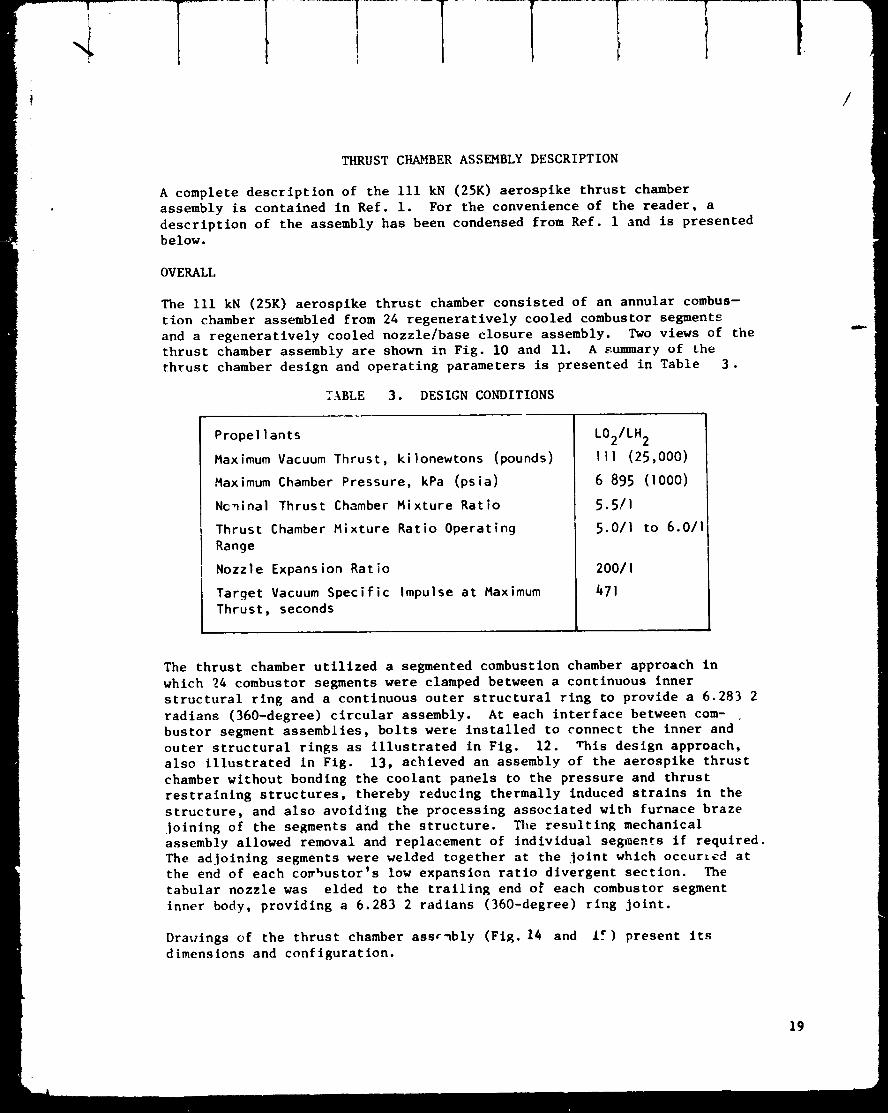
THRUST CHAMBER ASSEMBLY DESCRIPTION
A complete description of the 111 kN (25K) aerospike thrust chamber
assembly is contained in Ref. i. For the convenience of the reader, a
description of the assembly has been condensed from Ref. 1 and is presented
below.
OVERALL
The Iii kN (25K) aerospike thrust chamber consisted of an annular combus-
tion chamber assembled from 24 regeneratively cooled combustor segments
and a regeneratively cooled nozzle/base closure assembly. Two views of the
thrust chamber assembly are shown in Fig. I0 and Ii. A summary of the
thrust chamber design and operating parameters is presented in Table 3.
TABLE 3. DESIGN CONDITIONS
Propellants
Maximum Vacuum Thrust, kilonewtons (pounds)
Maximum Chamber Pressure, kPa (psia)
Nc_inal Thrust Chamber Mixture Ratio
Thrust Chamber Mixture Ratio Operating
Range
Nozzle Expansion Ratio
Target Vacuum Specific Impulse at Maximum
Thrust, seconds
LO2/LH 2
II1 (25,000)
6 895 (iO00)
5.5/I
5.0/I to 6.011
200/!
471
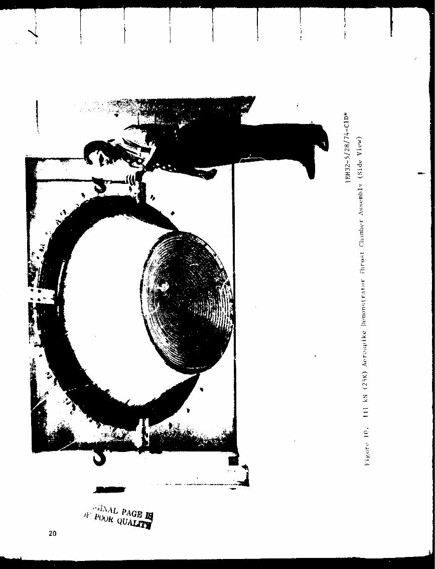
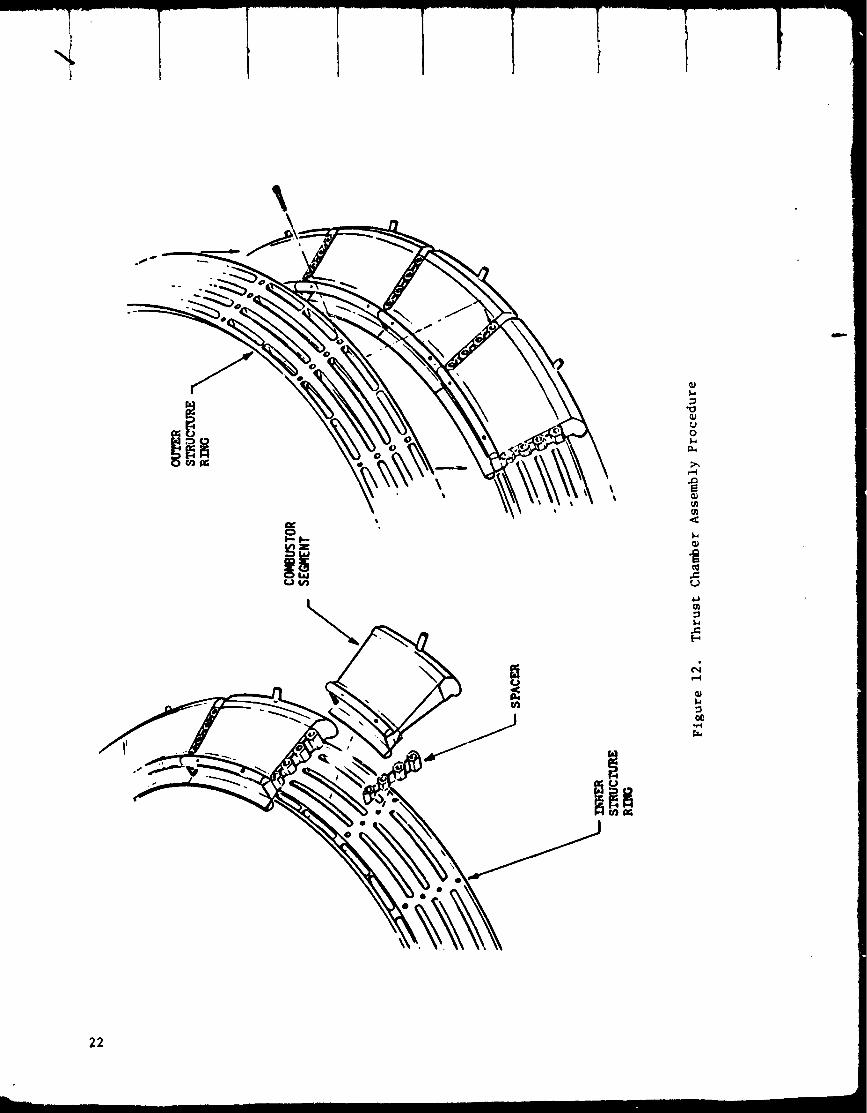
The thrust chamber utilized a segmented combustion chamber approach in
which 24 combustor segments were clamped between a continuous inner
structural ring and a continuous outer structural ring to provide a 6.283 2
radians (360-degree) circular assembly. At each interface between com-
bustor segment assemblies, bolts were installed to connect the inner and
outer structural rings as illustrated in Fig. 12. This design approach,
also illustrated in Fig. 13, achieved an assembly of the aerospike thrust
chamber without bonding the coolant panels to the pressure and thrust
restraining structures, thereby reducing thermally induced strains in the
structure, and also avoiding the processing associated with furnace braze
joining of the segments and the structure. The resulting mechanical
assembly allowed removal and replacement of individual segments if required.
The adjoining segments were welded together at the Joint which occurred at
the end of each co_bustor's low expansion ratio divergent section. The
tabular nozzle was elded to the trailing end of each combustor segment
inner body, providing a 6.283 2 radlans (360-degree) ring Joint.
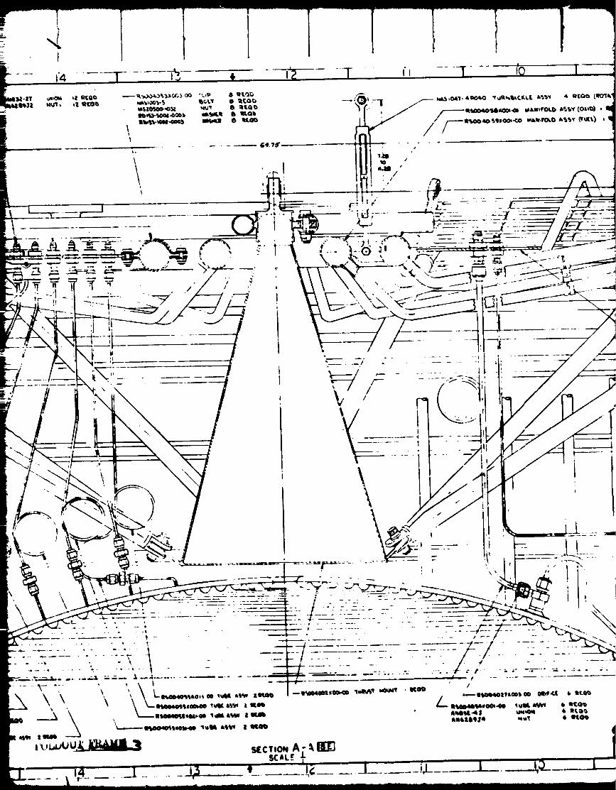
Drauings of the thrust chamber assrmbly (Fig. 14 and I_) present its
dimensions and configuration.
19
20
I
o,..q
>,
E
<
E
c,E
<
°
_L

I!
,llf.i.1
fJI
t'_ 0
I.z.l
I.
E
q2
I-
C_
I.
v
m-.
I.
21
Ic
_z
\
uo
_.,
"t
It,,
22
71
/ °Z
Z
m,x=ro
Go
,1-14.)m
0
l,J
,..1
00
,.-t
._..I
.i L'_ , 23124

PAGe,_INAI,
,, _ ()R QUI
,),
i
J
\
I
fi i
\
• <. _ .
'.\ "_',/ _ _\!
\'"\ / \
\
_o.' i/ i
/i
I
\
\

\
,4 I ..... _ i - i-Y_- ..... T ,, .... -T -- iQ |
FI
_ Nt3bOlil" llltOLIQ _.lR_lbt.C_.t.i L_,_ • UlEQI_ (IIO'IL'
,/ /--m_l,_._ _i._ro_ A_Y (o,_D) , I

Ii
I o• ¢IIOIPoLIII qivtll, _ID lllltal II -- L --
I "(l_rlL'Tf._ _++TO r.C'T')
* 1ti;00
I ..... ++ I
,.___-
/
• _-- --ll'WO4OSldlOOi.O0 IWll l'_,v 4 RtQ_
IlIIII'SI- I 't _ _ I_04_
• mlllllll ml'tl 41 1111,tl
:lSCX)40")_
F_IUTO 14. ThrustTosttn lAttl
IIICtlI_ I0 mO_ u**t ID+.lb'hf,L Inlto_lL Pill II_)+OI 004l
l+** *ei* l
i
I i ...... , a I
\
IIh14.I00S-I00% _+ 24 111101)IHoo40o4w+003-0o _'b_P.q I_+ _.tlMbII_00,4_04s00S,,,00 'ul_"bv4Jl, 141, III_
llDm-40o41 - t,%lo I1o_.+ It IItIo_)lit t_. - IocP,--Ioos _u_ lira t)
tqMio44o4:nl_o wl_tlt 1_ IICG_
IJl._J
Amlllg.- 11] _ 4 lifo0• 1411111 mi'l t Iltl_
F_lu_ 14. l_ust Chiber _seIbly llithTelting InstnIentat ionAttuhd
_6.... --F
/
t .its
J"
• IDO¢II4NOLI
.ors
.Iso
\
-p
/
RSCO4OOex
_SEE
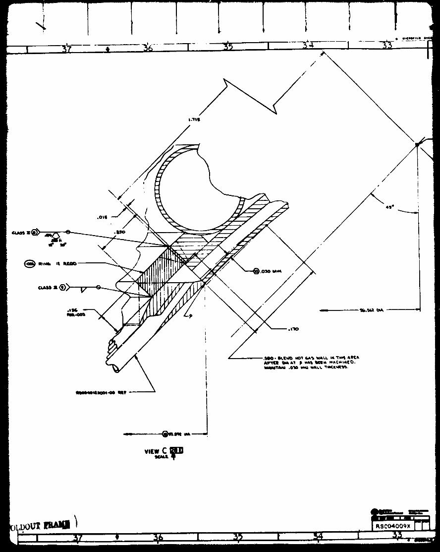
Thrust Chmmber Septents toTubular Nozzle AssemblyInterface Des/p Details
' " raJUC,'.t A;i¢.,"__
_Inm
Id
27
-- .... i 2S--- I 27

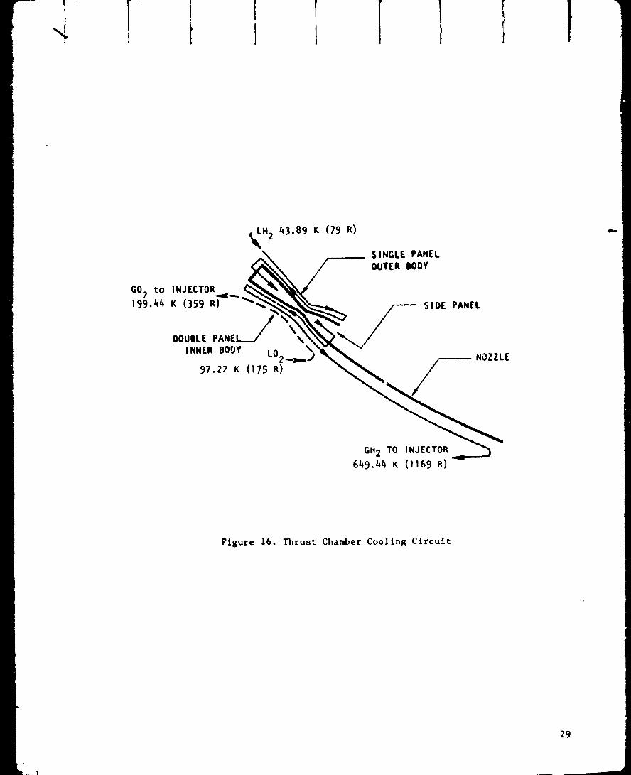
The cooling circuit for the thrust chamber, shown scPematically in Fig. 16,
consisted of a double-pass, combustor-first/nozzle-last type of circuit.
The hydrogen coolant first entered the combustor segment outer body wall
as a liquid, at a temperature of 43.89K(79 R), and cGmpleted a downpass
and uppass. This was followed by a downpass through the segment end panels,
an uppass and downpass through the segment inner body wall, and completion
of the circuit by flowing single pass down through the nozzle.
The hydrogen exited the nozzle, and was designed to feed to the injector,
as a _as at a temperature of 649.44K (1169 R). The oxidizer was used for
secondary cooling, entering the circuit as a liquid. 97.22 K (175 R), com-
pleting a single uppass through the double-paneled inner body wall, and
was then fed to the injector as a gas at a temperature of about 199.44 K
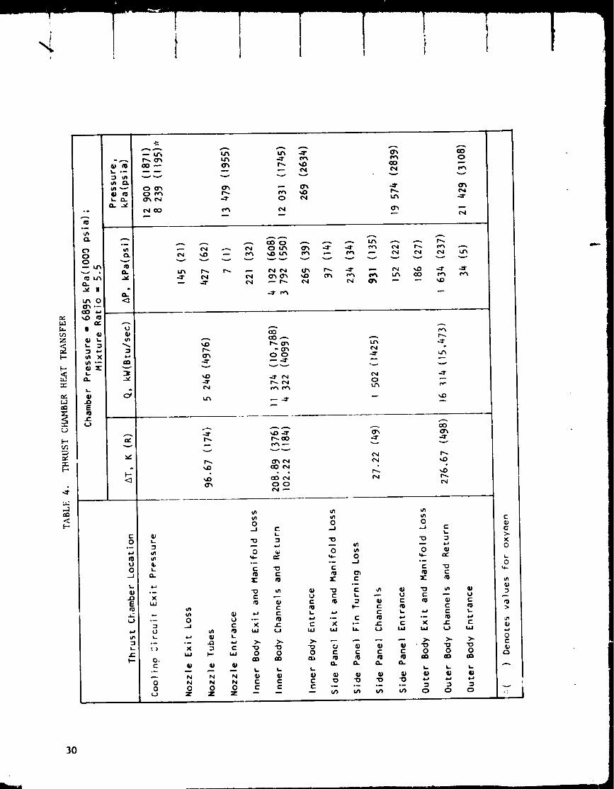
(359 R). The double-panel thrust chamber heat transfer and pressure loss
characteristics are noted in Table 4.
COHBUSTOR SECMENT DESIGN
The design criteria for the regeneratively cooled combustor segment were
established on the basis of extensive development experience gained from
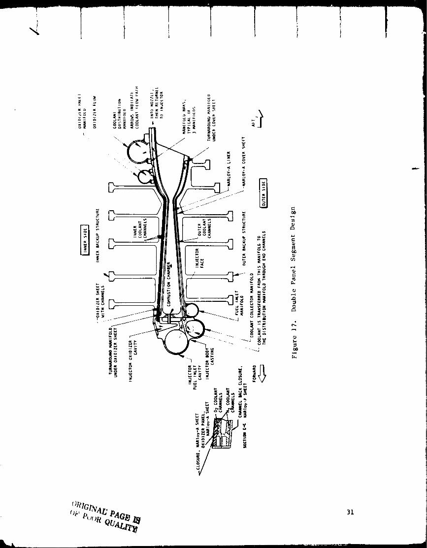
single segment test combustors. A sectional sketch of the segment design
is shown in Fig. 17.
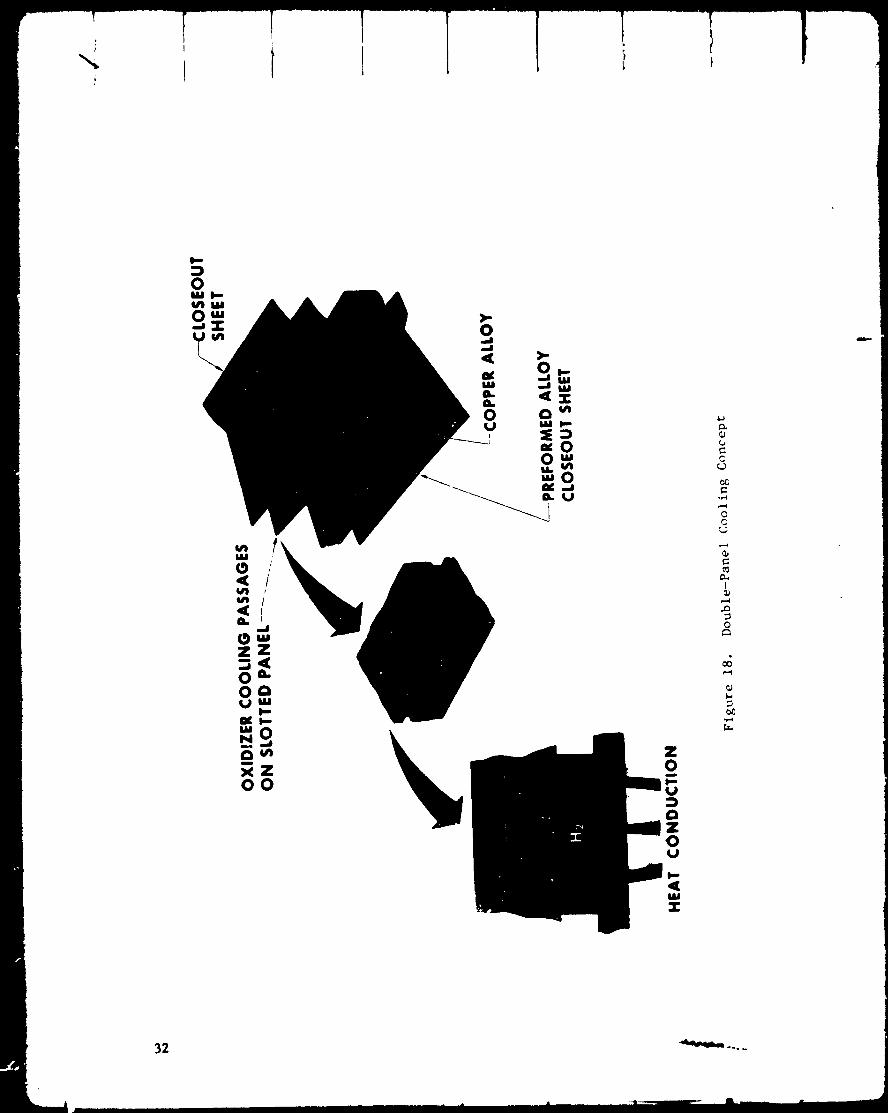
The segment consisted of a two-piece (i.e., inner and outer liner) NARIoy-A*
assembly as depicted in Fig. 18. The outer liner had a brazed-on NARIoy-A
closeout sheet, but the inner liner utilized a brazed-on NARIoy-A oxidizer
coolant panel closed out with a NARIoy-A cover sheet. All material was
machined from forgings.
The materials selected for the regeneratively cooled double-panel segment
were as follows:
i. Segment Liner - Machined wrought forging,NARloy-A material
2. Inlector Face - Integral with wrought liner, NARIoy-A materlal
3. Injector Body - Investment casting, 304L corrosion-resistant steel
4. Coolant Channel Closeout, Outer Body Liner - Furnace brazed
wrought NARIoy-A sheet
5. Coolant Channel Closeout, Inner Body Liner - Furnace brazed
NARIoy-A oxidizer coolant panel which is closed out with a
wrought NARIoy-A sheet
6. Injector Body-to-Face Joint - Furnace braze _oint
7. Manifold Shells - Minimum wall thickness, corrosion-reslstant
steel
*EARIoy-A is a silver-copper alloy (Rockwell International trademark)
_-_: I-_ I 1
_I_H2 h3.89 K (79 R)
SINGLE PANELOUTER BODY
GO2 to INJECTOR t.. "I99.4_ K (359 R) SIDE PANEL
DOUBLE %
INNER BO_Y LO2__D,._/
97.22 K (175 R)NOZZLE
GH2 TO INJECTOR
6h9.hh K (1169 R)
Flgure 16. Thrust Chamber Cooling Circuit
29
C
0o--
U
0
_J
K.
X_
E
u_
I..
0C
%.
u_
&.
O.
oI
X
w
o-
U
&...
()
O;
r"
0
0,,..)
O0
0
v
N
N
v
C
>-
X
0
¢0
e-
30
\\
e"
t_
e_
em
,4
31
Z0m
U
aZ0U
W
3:
C
0C
I
,-.4t_
0
.r-*
32 _ ....
The details of this design are described below.
Each NARIoy-A liner had 74 regenerative coolant passages machined into its
exterior wall. A preformed wrought NARIoy-A sheet 0.64-mm (0.025-inch)
thick was brazed into position to form the c_olant channel closeout for the
outer liner. An oxidizer coolant panel, 1.14-mm (O.045-inch) thick, with
73 machined, regenerative-coolant passages along with a closeout sheet,
0.38-mm (0.015 inch) thick, was brazed into position to form the closeout
for the inner liner. The inner and outer liner assemblies were then brazed
together. The injector face was made integral with the liner halves so
that a flat surface injector body-to-injector face joint could be furnace
brazed.
The design criteria for the segment geometry were established by development
segment testing and are presented in Table 5 .
DESIGN OF THRUST CHAblBER ASSF_IBI.Y
The complete thrust chamber assembly consisted of a combustor segment sub-
assembly attached to a truncated aerospike tubular nozzle as described below.
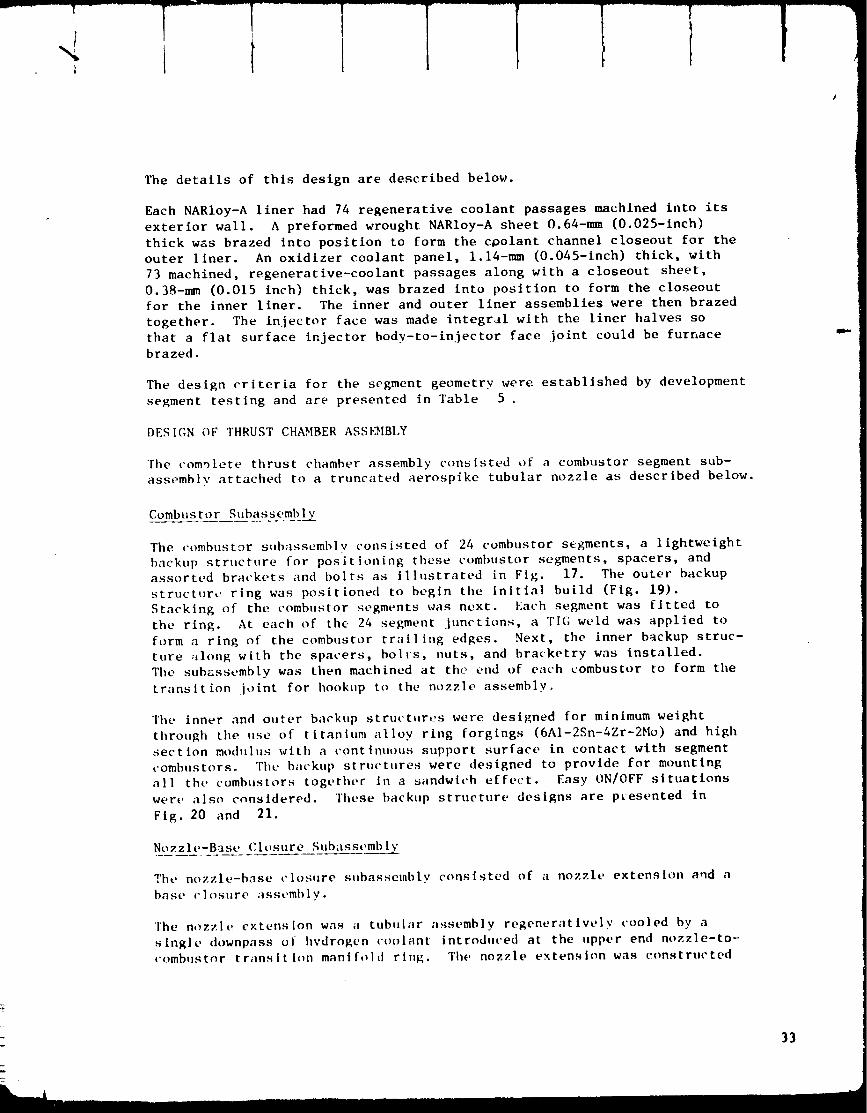
Combustor Subassembly
The combustor subassembly consisted of 24 combustor segments, a lightweight
backt,p structure for positioning these combustor segments, spacers, and
assorted brackets and bolts as illustrated in Fig. 17. The outer backup
structure ring was positioned to begin the initial build (Fig. 19).
Stacking of the combustor segments was next. Each segment was fitted to
the ring. At each of the 24 segment junctions, a "FIG weld was applied to
form a ring of the combustor trailing edges. Next, the inner backup struc-
ture :_Iong with the spacers, boll:s, nuts, and bracketry was installed.
The subassembly was then machined at the end of each combustor to form the
transition ioint for hook,p to the nozzle assembly.
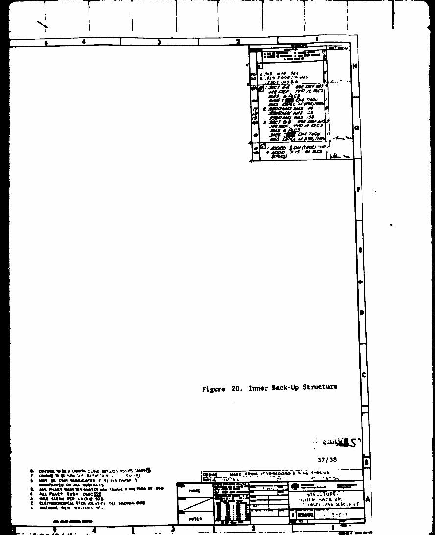
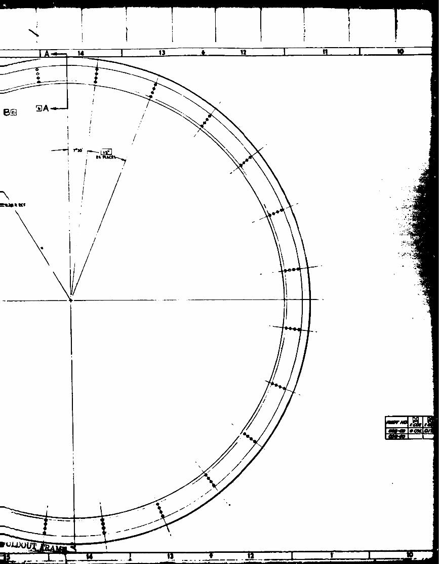
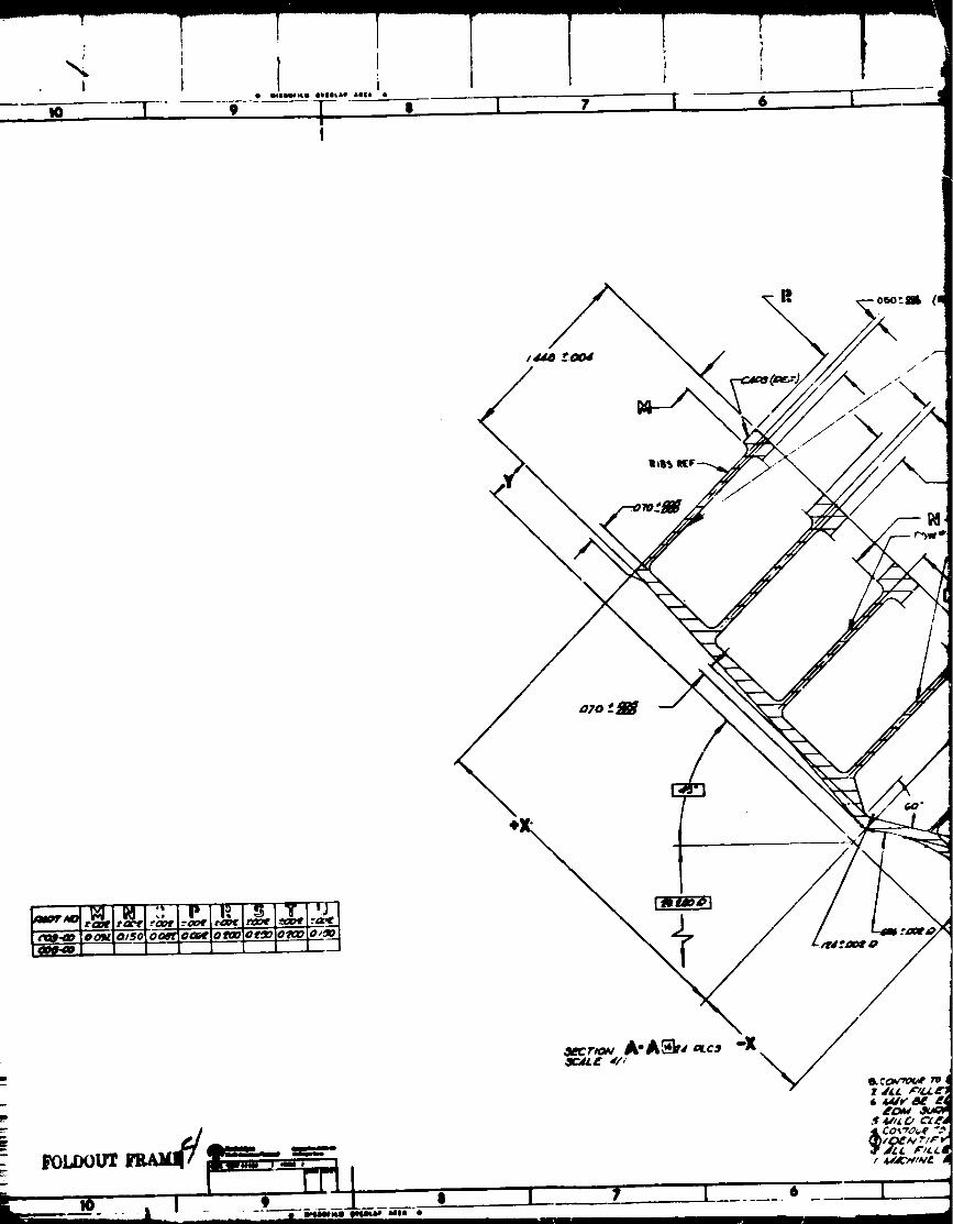
The inner and outer backup structures were designed for minimum weight
through the use of titanium alloy ring forgings (6A1-2Sn-4Zr-2Mo) and high
section mod-lus with a continuous support surface in contact with segment
comb,stors. The backup structures were designed to provide for mounting
all the cumbustors together in a sandwich effect. Easy ON/OFF situations
were also considered. These backup structure designs are pkesented in
Fig. 20 and 21.
Nozzle-Base Closure Subassembly
The nozzle-base closure subassembly consisted of a nozzle extension and a
base closure ;issembly.
The nozzle extension was a tubular assembly regeneratlvelv cooled by a
single downpass of hydrogen coolant introdnced at the upper end nozzle-to-
comb.stt_r transition manifold ring. The nozzle extension was constructed
33

oo
o
ooo
ou'%
0 ""
o ,_
34
"x
.IC
L)I
.4'
..4"I
e_
_J
old
,.-4
81I.i
aid
35/36
¢l
0
o

:3 [ n I
¥
\
\o
\
[B
_tw t-t_l
m
19 I Te I17 I 16
15
\
\
l
/./ I
-- .CM$¢.00S411 quq.AC.¢S

14 I 13 t
\
\
\
I
/
/

i
9 -T
s
/
\
\
\
/
\
f
, i I4 I
| rill lLlam llll ,._#.b-611l I_I&_II,IIINAI, Ills ,I_,_,11 rill_lbOQ04.001L lllAtllllll IdLI_ _,110.,. _'_",,
mmnn
T I
!
' I
I .ql_S d,_ 98trtrl$) *ool' a, v_as
• .Ill.Idler lc_,l ,_ - "
_ll_dldO AW,II ,*_
Filure 20. Inner Back-Up Structure
Z ll,.:_J_l_'"
37138
N_LI ¢90e4 _.'_II1400_0. I 'I,.-,4. ¢_.o4_
,p&e -_, • .
,o,lllI_ ".J_(l UII'.
,, ,-_,
I

24 2a ! n I; 21 20
toes14 IPutt. IS
/
$ _K.ts
II_ mt, X ¢.._ o_xt .... /
Iv.v
_J_Jt •
t+)I<I+;INAL PAOg 1_
oF PO_P, QUALITY

'le T 17• iqPqL_lLU OqPql01LsP aoeA •
16 15
0
Q
Q III_,V
/IjI
I
\
\
Z_D,,_I,t rE,'
/
It W
/
//
/
o
p s
t
_J
t/
/
/
t
t
m [ 9 | L 6 L__----J
[_._ Ioo_ia,sol ooet]oo_rlot_lot_olo_ol° "_--Ila_.._l I 1 1 I I i 1 ._1
I¢OI.£_UT

2
n
_d
W
x
J I
• J S_CJ JtWJ 0
_F
t_lP_ M4# /W$ /.,.',4 ¢_I00 44Lr W45 . .%"
M|---_
$ sn/O';_iV_v,_.T_,,. VI
_0
/
II
m)
Figure 21. Outer Back-Up Structure
39140

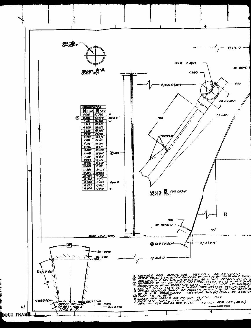
of 1590 Inconel 625 tubes. These tubes had a wall thickness of 0.13 mm
(0.005 inch) and were tapered from 2.79 mm (0.II0 inch) OD at the tran-
sition joint down to 1.78 ram (0.070 inch) OD at the nozzle base manifold.
The hot-gas-side transition ring was made of OFHC copper while the cold-
gas side was made of Inconel 625, as was the base manifold.
The coolant tubes were assembled on a brlzing fixture, alloyed, and then
furnace brazed.
The nozzle tube dimensions are shown in Fig. 22 .
Follow_ng machining, the nozzle assembly was welded to a base closure
assembly at the welding lip of the base manifold. A design drawing of the
base closure assembly is presented in Fig. 23. The base closure assembly
was a thin-shell pressure vessel configuration consisting of two 0.i0 mm
(0.0)4 inch) waffled 347 CREC sheets joined together by rivets to form a
double-walled dome. The small base bleed flow 0.045 kg/s (0.I0 Ib/sec) is
ducted into the cavity between the two walls and then discharged uniformly
into the dome base region through bleed holes.
Final Thrust Chamber Assembl_
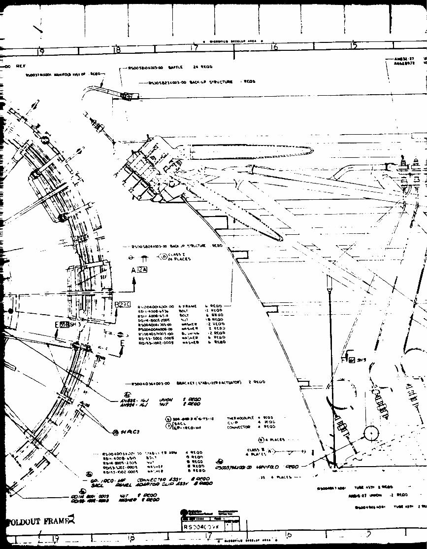
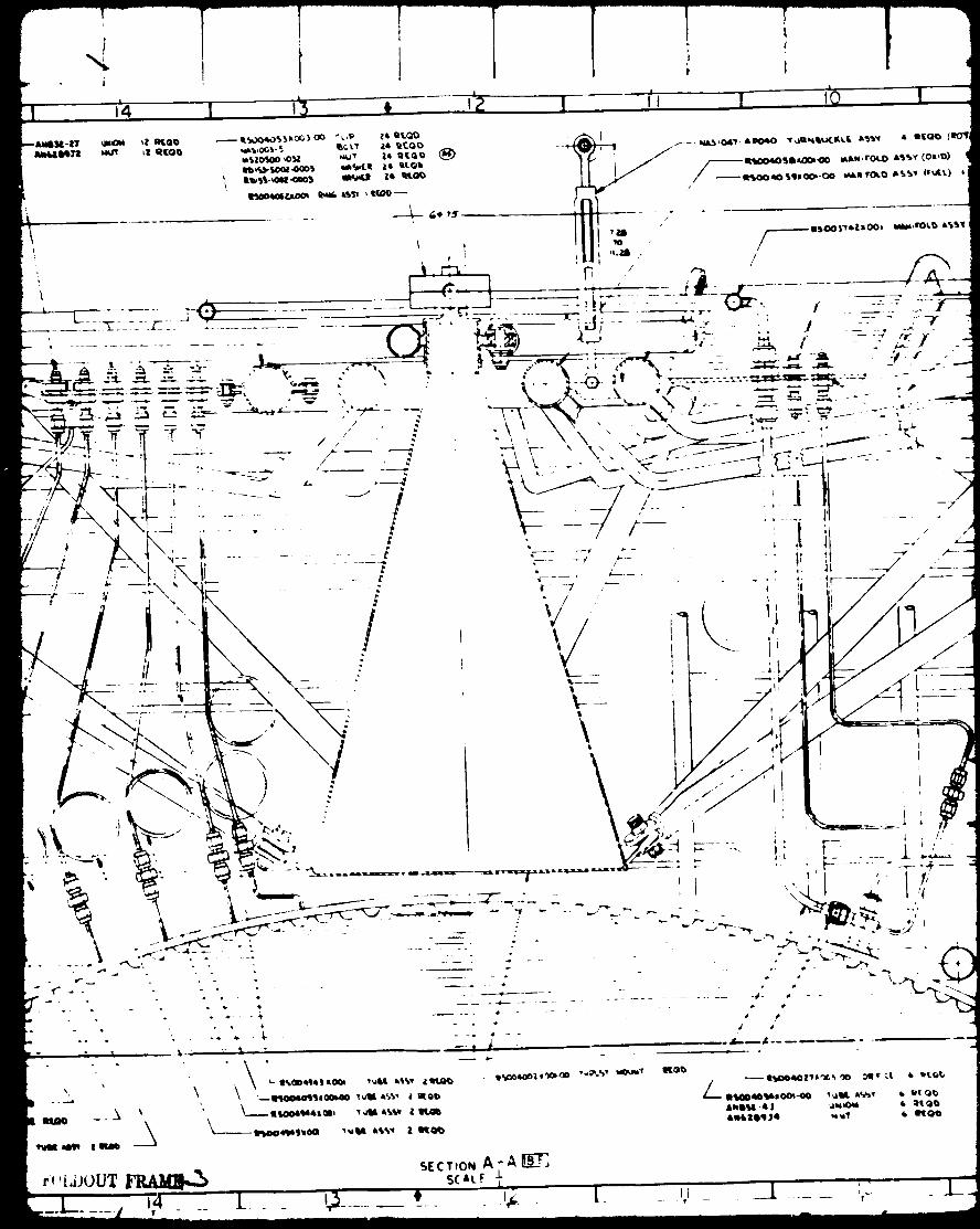
The final thrust chamker assembly consisted of the combustor subassembly,
nozzle-base closure subassembly, thrust mount assembly, manifold assembly,
and an assortment of brackets, bolts, nuts, etc. The design drawing of the
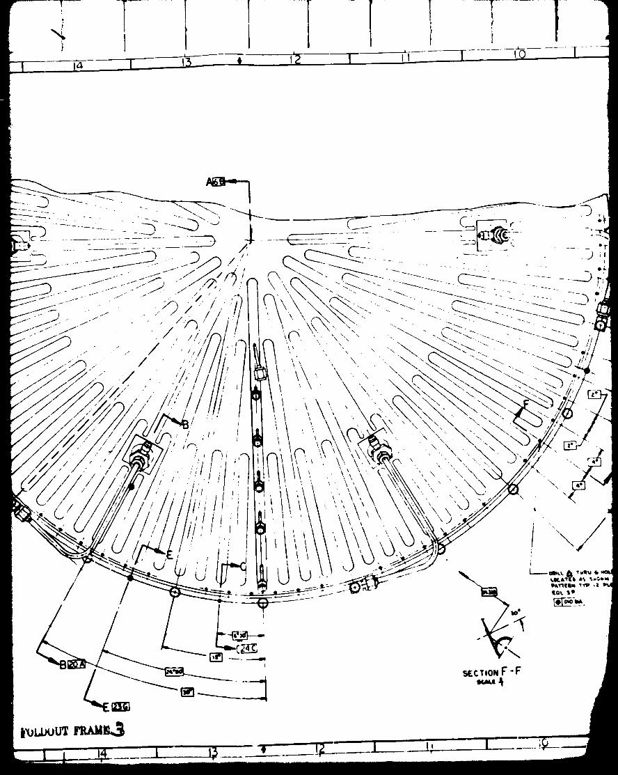
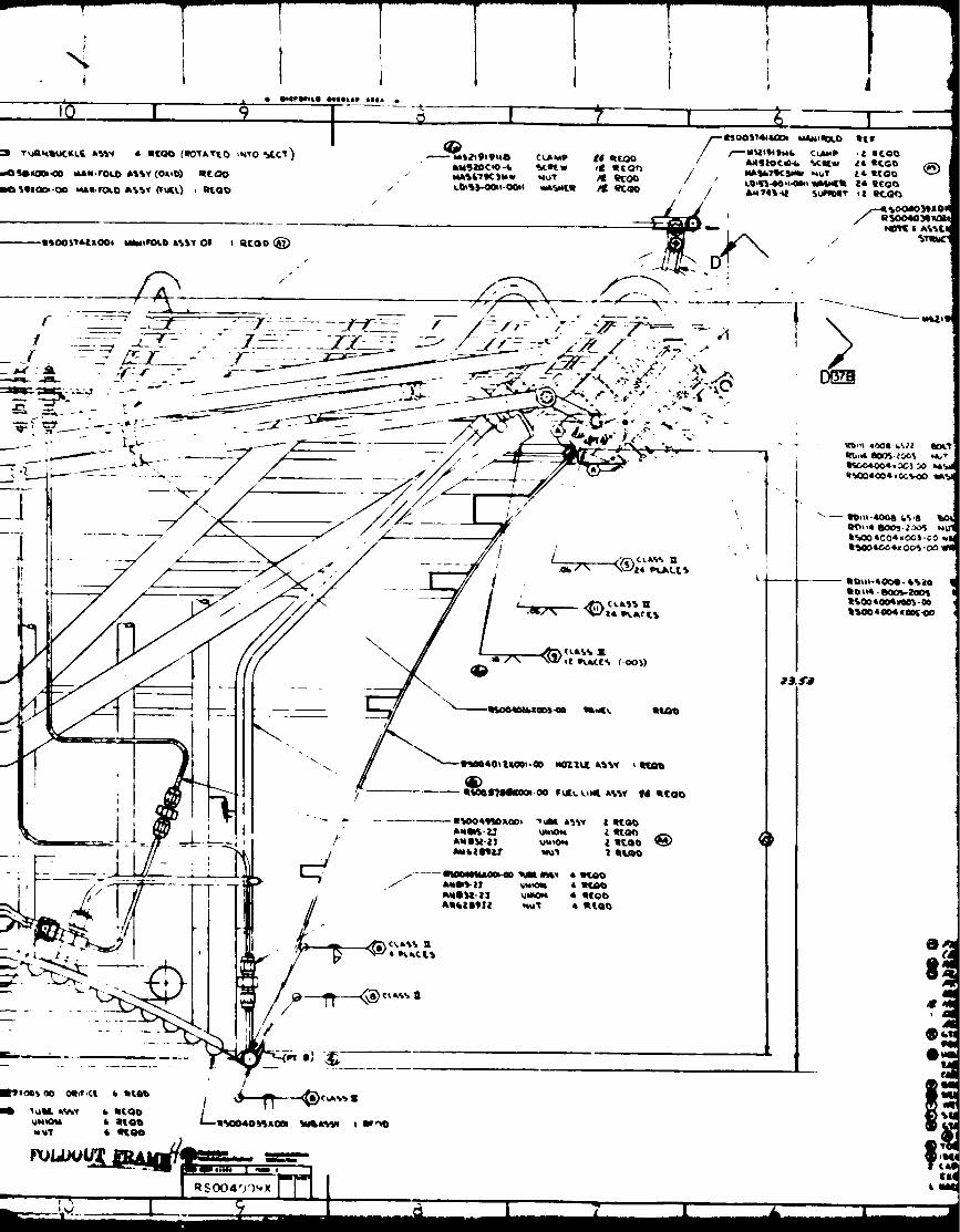
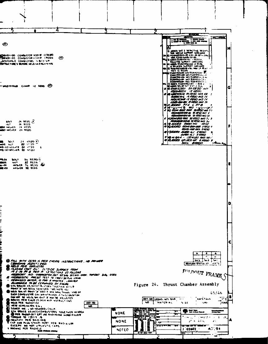
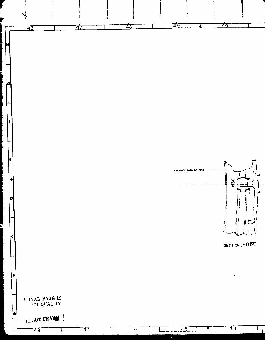
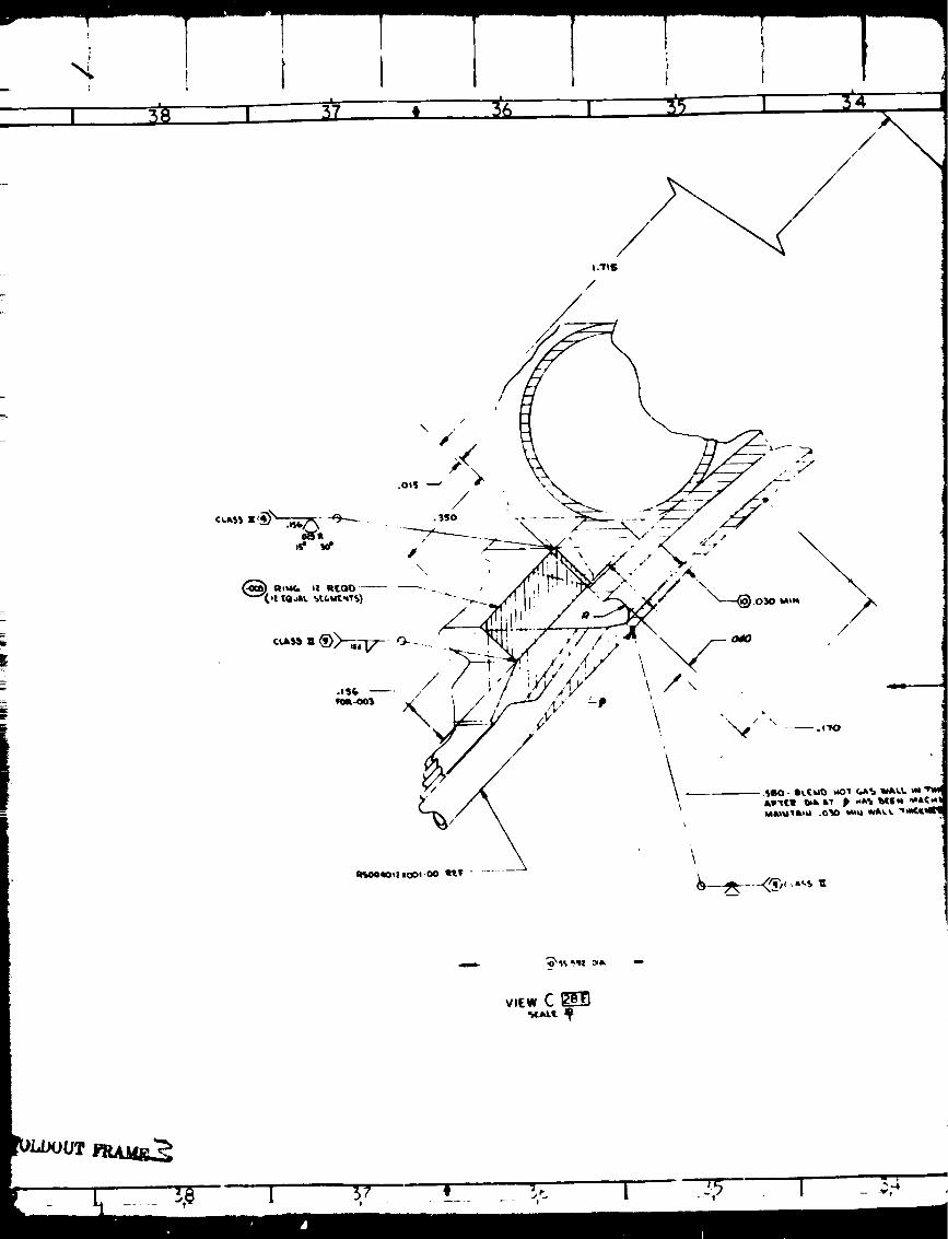
thrust chamber assembly is presented in Fig. 24 , and photographs of the
completed assembly are shown in Fig. I0 and ii.
The nozzle-base closure subassembly was ioined to the combustor subassembly
at the transition joint as shown in Fig. 24. This joint consisted of a
wrought NARIoy-A-to-OFHC copper TIG braze on the hot-gas side and a 21-6-9
CRES-to-lnconel 625 TIG weld (two places) on the cold-gas side. A small
common manifold was utilized to transfer tile hydrogen coolant discharge
from the 880 channels in the combined 24 combustor segments into the 1590
nozzle tubes.
41
I i I 4
!
d
I!

(,7(, 0 m-.
_" _; H
/
\_ _- 7"_s": o'/5"
Figure 22.
iImam m
tiII • I|g
_7 44t _v,d._ tZ#4r/ •,il- -
_,,_ . _lo,,o_._.
4a73 ,_c_4/_/G/xq 3" 4_....t_:.,_e/
oil I ami
Tapered b:ozzle Extension,Formed Contour Tube
4,
m
m

23 I 2'2
_ _--7_-_- _ CLUBS l
'vul_, 4 ILQU
SECT,ONC -C I1Tlll_r,vp 4 OLACLS
earl Ik_ u m_&_LL_[ .ah _tP
l _ OU lhT_Iti6
_-lOk
B
KCT,O_B -8 n'_r11
• IDJ¢IOqOLID I)IlILSP lil|l • j_
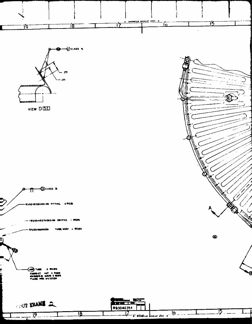
v:[w D.rT_
_)/_ASQO40Z61LO_O0_I_
X;_- •¢ptiQ
_-ilbOO4Ot'lliQO3b-O0 _vVr.L _
\
RSOO403_x
l
I ......;........ t¸i-
i'1 -1[ I
II

e&TSttU 5,fSD _T. e_.LC.Y.cJ
IF,O_ SD
S_CT00H A-A _'R!

4.--
411411 _ r
kllli I Ilmm IIiIm& ail_m
Hk ilI.QIS tl(Li_{b dLt) %_
3)&_b I_t£?,O,, _-t j. '
Z 4;q_40m_ "JI,4,d_"_ ,w41
J_ G/_
/
/
sttQ_)
Figure 23. Nozzle Base Closure Assembly
•111 I1! --II
\I
• _m_ _1 _C,010_
_T.DOUT FR z",T_ S
43/4_,
i
i
ii

\
f"
°o
/
t
I
\
\
I._ _ ,_
r
..
I
SCALF J-
T
!
I, i
IP'----T---
,%i
#
_*-OO ¢Oulkt_oit t._Of {If.GO
-wt4ll9_9,tl CL_P ll_ N£11O _)
_L_tR _1_ tl[G_
t
®
T T
d_t'_Jl_. _ J _1_ I
ioi
I
I
J •
, ,f it
SeCTiOND-D

r
___ ,_ ;',,,"_,___Z'"" "" " 4Q
,o
I; I
j-
m D-D _-¢
_ULI_UT YRAldl_ "
]
\/\.
\
\\
_41 3z . _..... _,. 1. --, --_,

i
.
/
//
Ii ,IDHIIIOflLI IVlIILIP llll •
1; I
'qL
Iojoo40_oo1-O0 Rile
W xoo14o
/
\4_L e
t
B
/
YI,%.,_. _ -----'---_
I"_0
1[
gTg_,sOol-Oo _cr
eLI __Z _L"- 't'/- - ,Jr c)
¢_ I /-_x,__ _,ub_ _&ILl_Lt_-_"
1
P
/////
/V
SECTION 8-BI
SCA_.E T

t
CL•
ILi _llll
IL IllB
m a_.xo ..-
--_ Oa_r _
of
tic _P
7.
SECTIONB-B$CAL.E
I
,'4

THRUST CHAMBER DAMAGE
This section contains a description of the damage that was incurred by the
thrust chamber during test 74-005, the last test firing conducted on Air
Force contract F04611-67-C-0116, and of the repair efforts to the thrust
chamber that were conducted under the _uspices of the U. S. Air Force. A
photo of the interior of the thrust chamber assembly after the fire is
shown in Fig. 25.
The damage incurred during test 74-005 may be cataloged as follows:
• Five combustors, at locations No. 16 through 20 of Fig. 26,
sustained such severe fire damage that they could not be used.
• Approximately one-quarter of the titanium inner backup ring
was burned away
• Two small areas of the outer titanium backup ring were
sufficiently burned to require metal replacement
• The ignition manifold and the propellant feedllnes were
burned so as to require approximately 50% replacement
Components of the thrust mount, i.e., some of the struts
and the central cone, suffered burn damage. Some parts
required complete replacement and others required repair
of damaged areas.
• Approximately 30% of the 1590 nozzle tubes had small areas
burned away on the cold side, resulting in leaks in the
burned areas
• All of the instrumentation, wiring, and pressure connections
were destroyed
After a period of damage assessment, it was determined that all of the
damage was repairable. The modular nature of the combustor segments
permits the removal of damaged segments, their repair, and replacement.
The backup structure and thrust mount components are bolted on, so may
be removed for repair and/or replacement. The ignition and propellant
feed manifolding is readily accessible for repair and replacement. Finally,
a company-sponsored nozzle tube repair program had demonstrated that
excellent nozzle tube repairs were feasible, and could return the nozzleto a flreable condition.

1
4f
r_)i
!
t.)
,<
G)m_n,<
1
f rl y
.. . , _ ,
L
Y_
.3
,/.
L
L"
,1/'l"

1
THRUST CHAMBER DISASSEMBLY AND REPAIR
DISASSEMBLY
A photograph of the interior of the 111 kN (25K) aerospike thrust chamber
is shown in Fig. 27. It is possible to identify on the photograph many of
the elements that go to make up the thrust chamber assembly, i.e., the
nozzle, the combustors, the inner and outer backup rings, the support
structure which carries the thrust from the backup rings to the central
gimbal point; the fuel, oxygen, and ignition manifolding; and tile instru-
mentation hookups. Some disassembly effort was funded under the previous
Air Force contract and it had been mostly accomplished at the start of the
subject NASA contract. The disassembly had made it clear that it would benecessary to refurbish or replace five of the combustors, the inner and
outer backup rings, certain other components of the thrust structure, theinterior of the nozzle and many of the components of the manifelding.
CO._[PONENT REPAIR OR REPLACEMENT
The nature of the aerospike thrust chamber assembly is such that it is
possible to effect repairs by replacing damaged components with functional
components, i.e., individual components are readily replaced without seri-
ously disturbing the adjacent components. However, where assembly is by
br:_zing or welding, it is necessary to cut the damaged component out, and
this may render it unsuitable for further use. The repair and replacement
effort is described, by component, in the material below.
COMBUSTOR REPAIR
Background
During the disassembly and inspection of the damaged thrust chamber assembly,
it was determined that 5 of the 24 combustors had been so severly damaged
that they needed complete replacement. There were no usable complete spare
combustors on hmd, but there were a number of combustors that had some
usable parts. The major elements of a combustor assembly may be visualized
as consisting of the injector assembly, the inner liner (which has both a
hydrogen and oxygen cooling circuit), an0 the outer liner (which has only a
hydrogen cooling circuit). These three subassemblies are joined b_ brazing
and welding (there are no bolted joints) into an integral combustor.
The pl-.n devised for combustor replacement involved cannibalization of
portions of the existing spar_ combustors so as to utilize them in combina-
tion with portions of other tombustors, or with new components, to produceviable combustors suit Jt_l_ f ,r welding in place on the existing thru.qt
chamber assembly. This is ,t, lieved to be the first time dissection and
reassembly of such we.ded combustors was attempted. It was made possible
by the unique fabrication scheme of the 111 kN (25K) aerospike combustors
which is illustrated In Pig. 28.
53
.<
LIJ
L)----)
--')
(.J
L_J
C)
I.IJ_J
I-_r
_0('M
i('M
_Ei.i
0
_J
_J=
C=E
_J
j::
_J
.£
E
E
L
l.-,
o_
54
\
o,_,,.,,
}..,
0
Gr,,,;
¢::
E_
5.,
*,.,.4

t
Work was begun on the fabrication of five combustors, so as to r_place
the missing five on the thrust chamber assembly. Table 6 lists the five
rebuilt combustors from which the replacements for the assembly were to
be selected.
TABLE 6. COMBUSTOR BODY-INJECTOR USAGE
F
Combustor Segment
IdentifiCation
Unit No.
507R
510R
509R
515R
535(N)
InjectorUnit No.
506
518
NEW
NEW
NEW
R = rebuilt N = new
Inner Liner
Unit No.
507
510
New liner, coolantpanel, cover sheet
and end plates
Outer Liner
Unit No.
507
510
509
515
New liner, cover
sheet, and end
plate
Interpropellant Leakage
Experience during the initial fabrication of the combustors had shown
occasional leakage between the fuel and oxidizer circuits. On the repair
program, a gaseous pressure and leak test on the nozzle and the 19 combus-
tots that remain attached to it was conducted prior to initiating repairs.
This leak testing was undertaken to assess the extent of any leakage be_
tween the hydrogen and oxygen cooling circuits in each of the 19 combustors.
The testing was conducted at this time so as to be able to assess the
impact of the conditions found upon the schedule and resources required
for the chamber repair and hot-fire test program.
The absence of 5 of the 24 combustors on the existing thrust chamber
assembly made it impractical to secure a completely leak-free hydrogen
cooling circuit and it was therefor_ not possible to apply hydrostatic
pressure by the conventional means of a high-pressure, very-low-volume
capacity positive displacement pump. The procedure followed was to plug
off the exit of each of the nozzle tubes by dipping the aft nozzle mani-
fold into a pool of melted paraffin and allowing it to solidify. The
hydrogen inlet of each combustor was then connected, in turn, to a supply
of gaseous nitrogen at approximately 6 895 kPa (I000 psi). Commercially
pure methane in an amount sufficient to provide approximately 1% of weight
of methane in the pressurizing nitrogen was added to the pressurant just
upstream of the combustor inlet. A low-pressure, pure nitrogen purge wasalso admitted into the oxygen manifold of the injector of the combustor
being tested and was exhausted from the oxygen inlet manifold of that
56

-4! I
! I i i
combustor. This nitrogen (being purged through the oxygen circuit) was
then routed through a combustibles meter and analyzed for methane content.
In this manner, it was possible to measure the amount of nitrogen leakage,
if any, between the hydrogen and oxygen circuits of the combustor being
tested while the circuits were subjected to the same pressure differential
as would exist during firing at rated chamber pressure conditions. On the
basis of the measured nitrogen leakage, it was then possible to estimate
the amount of hydrogen leakage that would exist under firing conditions.
The test procedure was capable of measuring minute leakage in a reproducible
manner. The results indicated that none of the combustors had sufficient
leakage to cause a local concentration of hydrogen in the oxygen of as
much as 5 percent of the flammability limit concentration. It was thereby
determined that correction of interpropellant leakage in the 19 existing
combustors was unnecessary.
Combustors Usin$ New Inner Liners
Three of the rebuilt combustors were dependent on new inner liners for
completion. The necessary new combustor liner details, i.e., hydrogen
panels, oxygen panels, oxygen panel cover sheets, etc., to support the
combustor fabrication plan of Table 6 were requisitioned early in the
program. These details were fabricated both in-house and by outside
vendors. Deliveries of the details were completed during the second
quarter. The three new inner liner assemblies for units 509R, 515R, and
535, were put through their brazing and assembly cycles. One new outer
liner for unit 535 was also successfully put through its brazing cycle.
The existing outer liners for units 509R and 515R were reworked to braze
in new injector face plates. By mid-June, at which point fabrication
effort on this hardware was halted, the inner and outer liners for units
509R, 515R, and 535 had been brought to the point where match machining
of the inner and outer liners preparatory to their assembly bv brazing
could be undertaken. The fabrication of these components was satisfacto-
rily accomplished.
S u.pportin $ Combustor Details
In addition to the major parts that go into the inner and outer liners
in the injector assemblies, there are a large number of supporting details
that go to make up each assembly. These too were released and satls-
factorily fabricated by mid-June.
Combustor Units 507R and 510R
These two rebuilt combustors were planned to utilize existing inner and
outer liners as indicated in Table 6. Th,,v had been partially completed
under the sponsorship of the previous Air Force contract. Both of these
combustors encountered problems during the first quarter with cover sheet
cracking during the final assembly operation on the manifolds of the
inner liner. 507R had cracks in the l,OX panel cover sheet. 510R developed
cra,_s in the fuel panel closeout sheet b,,tween ttle l,OX inlet manifold and
57

the fuel distribution manifold. A repair plan was devised that involved
subjecting each combustor to what was intended to be a final furnace braze
repair cycle. The metal fitting to prepare for brazing is illustrated in
Fig. 29 and 30.
The triangular insert patch of Fig. 29 was successfully brazed to the inner
liner of 507R, as illustrated in Fig. 31. However, on hydrostatic pressure
test, it was found that a new crack, approximately 50.8 mm (2 inches) long,
had occurred lust aft of tile oxygen outlet manifold on the inner liner LOX
cover ,_heet. A repair to this crack was attempted using Tit; brazing with
Nioro braze alloy. The repair effort was unstlccessful in that tile material
cracked at the edge of the fillet formed between the braze alloy and the
parent material. EvaLuation of this condition indicated that further
attempts at TIG braze repairs would likely result in further cracking, so
a repair procedure utilizing furnace brazing with the relatively low melt-
ing point, "BT" alloy (727. Ag, 287 Cu), was attempted. This final braze
repair effort was apparently successful in repairing the crack at the
forward joint. 507R was then put through the standard hydrostatic pres-
sure test, which involves a 24 821 kPa (_600 psi) hydrostatic pressure in
the fuel side and a 1517 kPa (220 psi) pr_,_sure in the oxygen circuit.
507R successfully withstood the fuel side pressure testing without luakage
but during the oxygen side pressure testing !cakag_., in the oxygen panel
cover sheet was encountered through what appeared to be a series of small
cracks in the cover sheet. "[his condit ion is illustrated in Fi_. 32.
tlnit 510R, which had developed cracks in the fuel p,tnel cioseout sheet
between the LOX inlet manifold and the fuel distribution manifold, and
also some small seepage leaks in the oxygen panel cover sheet at locations
that had been repaired during initial fabrication (Fig. 30) was also put
through a series of repair actions. Leaks between the oxygen inlet mani-
fold and intermediate fuel manifold were. successfully repaired bv Fit;
brazing. A furnace braze cycle was employed to correct successtull," the
ox,vgcn leak,< through tile oxygen panel covt, r sheet, with results sl/owtl ill
Fig. 33. }tvdrostatic pressure testing of unit 51()R on compit, t i<m ot tl,.est'
repairs resulted in dwtection of a crack in thv outv:r liner fucl panel
cover sheet on the ri,_;ht hand side el tilt, bell-stl:lpt,,t nozzle (below til,'
throat), t, onsistent with standard rvpair proct.d,ires, a il(; braze rt,pair
to this cr,lck rising Ni_ro braze ;lllov _,,l,,_ ;ittemptcd, but resulted in ,l
s_,c_uld crack in tile matt, rial adi,icent t,_ ttw r_,pnirvd locati,nl.

i -I I
\
,,.-4
I
'42,
"-T
I
",.ft.
;Z
7"
_C
,M
[) _tsrs
, ; )q'L,'.C}t .\L,L'I'Y
_9
\
i
rj
I
C-,
-_
I
/
_f
°_
_)()
0_,4
0
0_,,4
°_,4
6!
Figure _2. Photo of Crack in Unit 307R LOXCover Sheet (10X Hagnification)
62

t
t,
"l';lx""_L' PA (';,F_Z,.Q
r
,
t
I
r_
k._,
Ie-j
l"
_L
x, I iI
The investigation took two paths, development of techniques to repair the
cover sheet cracks, and research into the causes and significance of the
cracks.
Final Repair Efforts on Combustors 507R and 510R
A repair concept was developed for the NARIoy-A cover sheet cracks ofcombustor units 507R and 310R which involved dishing out the cracked
area and electrodepositing copper into the groove in sufficient depth to
provide the necessary structural strength to contain the internal pressure.
The repair concept is illustrated in Fig. 34. Electrodeposited copper has
a minimum yield strength of 140 MPa (20K psi) and a minimum ultimate
strength of 280 MPa (40K psi) at 21 C (70 F) as compared to i00 MPa (14K
psi) and 210 MPa (30K psi), respectively, for aged NARIoy-A. The deposi-
tion technique used was that of cell plating, in which a small electro-
plating cell is clamped to the side of the part to be repaired rather than
submerging the whole part in the plating solution.
Several NARIoy samples were first fabricated to permit experimentation
with various methods for activating the NARIoy surface to prepare it for
copper plating and also to explore means for closing up the crack at the
base of the dished area to be plated. The NARIoy used for the samples
proved to be extremely difficult to crack, indicating that it had not been
subjected to embrittlement. The activation procedures investigated included
anodic and chemical cleaning. The crack stopping methods included material
removal and overplating at the ends. Properly plated samples were achieved
with the chemical method of activation and the ov_rplating method of crack
stopping, and the samples were found to have excel±ent adhesion as demon-
strated by baking at 537.8 C (i000 F) without blistering.
Combustor unit 510R was then prepared for cell plating. Because the
cracked area on 510R had been previously but unsuccessfully repaired with
Nioro TIG braze, it was necessary to grind away all the TIG brazed area
prior to cell plating. It is generally not possible to activate gold-
containing surfaces sufficiently to secure reasonable electroplating adhe-
sion. The opened-up channels on 510R were then filled with Rigidax wax
and the surface electroplated until the deposit had grown beyond the
original level. A photo showing the setup for cell plating of unit 510R
is s|10wn in Fig. 35. lllust_ated is the cell pump, copper solution, and
power supply.
Unit 510R was then subjected to cryogenic shock testing in which liquid
nitrogen was flowed through the chamber until liquid issued from the exit
and then permitted to warm up. This procedure was repeated three times.
Tile unit was then subjected to a 24 821 kPa (3600 psi) hydrostatic proof
pressure test on the fuel circuit and a i0 342 kPa (1500 psi) hydrostatic
proof pressure test on the oxygen cfrcult. The patched area of t|ie fuel
circuit successfully withstood the cryogenic shock testing and the proof
pressure test, but leaks were detected at the inner liner fuel and oxidizer

?
/
/
f
tl
t
I
\.\
,)
. f ELEC1MO-DEPOSITED\ COPPERPERIMETER
\
__ _-_RBIOVED CRACK
'1 ! _ MATERIAL REMOVAL
'_ 'i _ PERIMETER
t : I
1 / / p
-- ELECTRO-OEPOSITEDCOPPER
BLEND SURFACEDISHED OUT CAVITY
NARIoy-A LINER
NARlo¥-A COVERSHE
RIGIDAX FILLER
Figure 34. Crack Repair Concept
55

t
#
\
I
I
_.=,
._**=
r,_
66
! I IiIi q
i
manifolds. Several unsuccessful attempts at "touch up" repairs were made.
The manifold shells in question were then partially removed and it was
determined that these fuel and oxidizer manifolds needed extensive repair.
Repairs to these manifolds were effected by removing the entire shells of
the manifolds, rebuilding the attachment lips on the liner and replacing
the shells. These manifold repairs were apparently successful. The
assembly was again subjected to a three-cycle cryogenic shock test by
passing liquid nitrogen through the fuel side. After the shock test, a
fuel side hydrostatic pressure test was conducted, which indicated that
another NARIoy crack had developed in the outer liner, at approximately
the "opposite hand" condition from the previously repaired crack. The
area in which the crack appeared is believed to have been only minimally
affected by the thermal strains imposed by the manifold repair work, which
was conducted on the inner liner. It is believed that the new crack
resulted primarily from the additional thermal strains imposed by the cryo-
genic shock testing. On the basis of this experience, it was concluded
that 510R was unlikely to be a suitable combustor for assembly to the
thrust chamber.
The NAR[ov cracking problem with unit 507R involved the oxidizer panel
cover sheet on the inner liner. Repair of this area was recognized to be
more challenging than the repair of unit 51OR, so its preparation and
plating was held untii results with 5IOR had been obtained, tin making a
thorough examination of unit 507R preparatory to preparation for plating,it was found that there were relatively large numbers of small cracks,
and that cell plating would tend to be quite tedious as many of them wm_ld
have to be plated in series. :\dditionally, one could not be certain thatall cracks had been identified until some of the larger defects had been
covered. For these reasons, it was decided to apply electrodeposited
copper (ED) over the entire LOX panel cover sheet of unit 507R. llowewr,
ED copper cannot be expected to adi_ere to the areas that had been TIG
brazt, repaired because of the noble metal content of the braze alloys.Ti_ese areas were masked off prior to eleccrodeposition of the c,_pper, the
surface was prepared for plating by carefully removing 0.13 mm (0.005 inch)to 0.25 mm (0.010 inch) of the existing NARloy material by hand sanding.
Guidance m; to the thickness of NARloy material removed and the thickness
of the laver of electrodeposited copper applied was obtained by taking
caliper measurements of the thick'ness of the combustor at a relativeiy
fin,, grid of stations. Approximately 0.76 - 1.02 mm (0.030 - 0.040 inch)thtckness of til_ copper was then applied by immersing the entire combustor
in an electroplating bath. The copper thickness was then hand dressed
_o provide an average copper surface of 0.5[ n_n (0.020 inch) above thelocation of tile original NARloy surface. This procedure is acceptablebecause O.51 mm (0.020 inch) thick shims are normally applied between the
combustor surface and tile inner ba,ckup ring. A photo of tile inner surface
of combustor 507R after the application of the EI) copper is shown In Fig. 36.
After Ell copper application to the inner liner, unit 507R was sublected
to a three-cycle cryogenic shock test as previously described for unit51OR and then to a 10 342 kl'a (1500 psi) hydrostatic pressure test of tile
oxldlz,.r circuit. No leaks were observed on the hwlrostatlc pressure test,
_7

i I
J
I
|
r._
L2"
c
".,E
68 • _ t, _' _(.,_......
but when the unit was subsequently leak tested at 1379 kPa (200 psi) helium
pressure, it was found that there were about six leaks around the periphery
of the ED copper plating. These leaks did not issue from under the ED
copper plating itself but, rather, from beneath the Nioro TIG weld fillet
that runs along the upper edge of the LOX cover sheet, from the lower edge
of the triangular patch previously installed at the upper left-hand corner
of the LOX cover sheet, and from a small crack in the original NARIoy at
the upper left-hand edge of the ED copper cover. This small NARIoy crack
had been masked during ED copper plating and, thus, not covered. A repair
of these leaks was attempted in which the leaking zones were covered with
Nioro braze alloy applied with a TIG torch. Upon pressure checking 507R
after this latest repair effort, it was found that while the six leaks
appeared to have been repaired, a very large interpropellant leak was
now present, apparently caused by the TIG torch repairs. This interpro-
pellant leak was approximately six times the size of the maximum inter-
propellant leak observed during the interpropeilant leak check reported
previously. Additionally, the fuel circuit of combustor 507R was put
through a hydrostatic pressure test. During that test, the intermediate
[uel manifold (located at the aft end of the inner llner) burst at hydro-
static pressure test of approximately 20 684 kPa (3000 psi). It had
previously b_ through two hydrostatic pressure test cycles up to 24 821
kPa (3600 psij. While the fuel manifold could be repaired, the large inter-
propellant leak in 507R clearly made it unacceptable for utilization on the
thrust chamber.
NARIoy-A CRACKING INVESTIGATION
Beginning in July 1976, it became evident that the NARIoy-A coversheet
cracking being experienced on combustor units 507R and 510R was not cDn-
sistent with the ductile behavior typical of NARIoy-A. A metallurgical and
historical investigation, concurrent with the repair effort on 507R and
51OR, was conducted to understand the problem and its implications ior all
of the combustors.
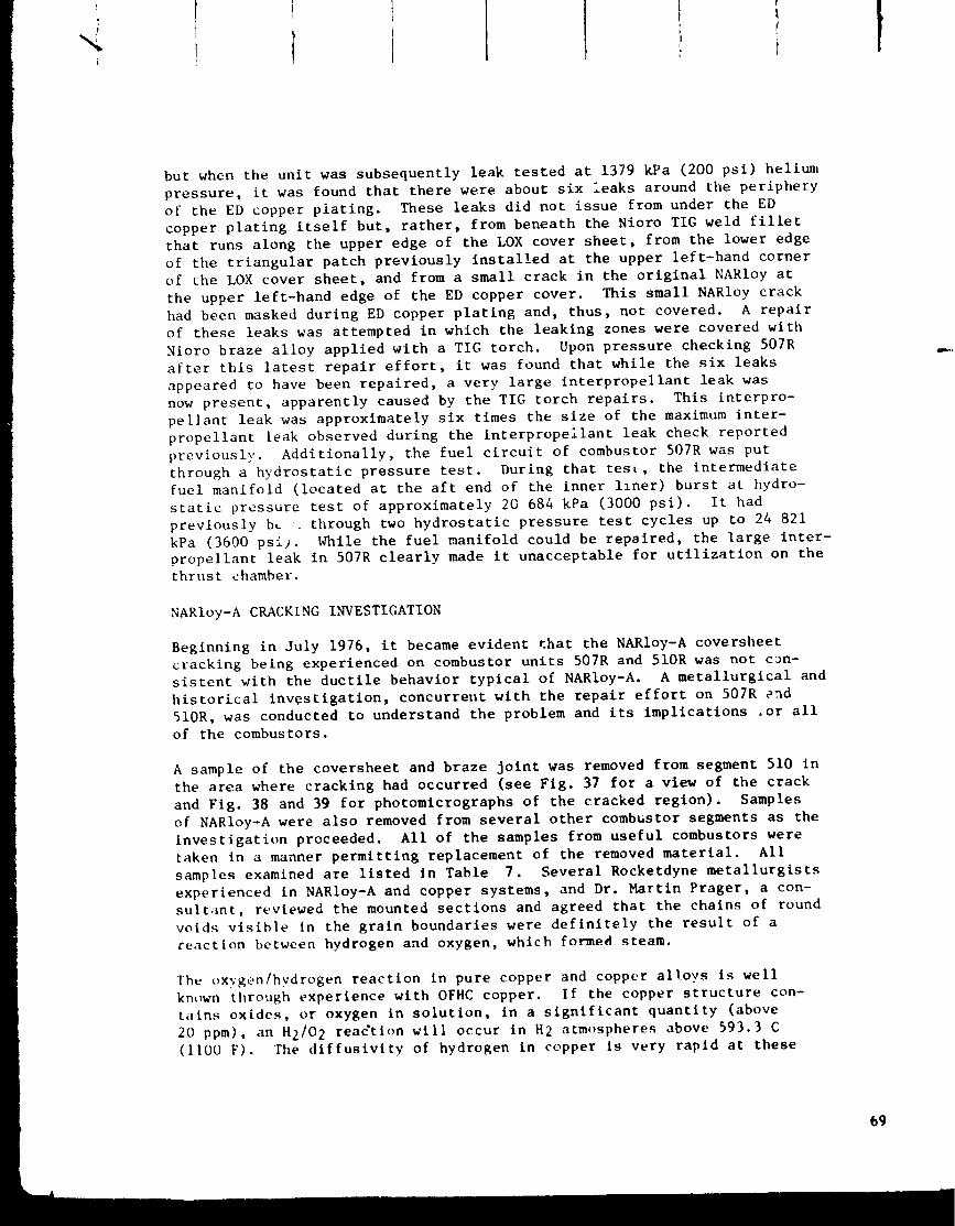
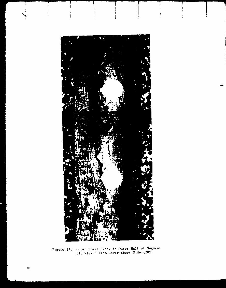
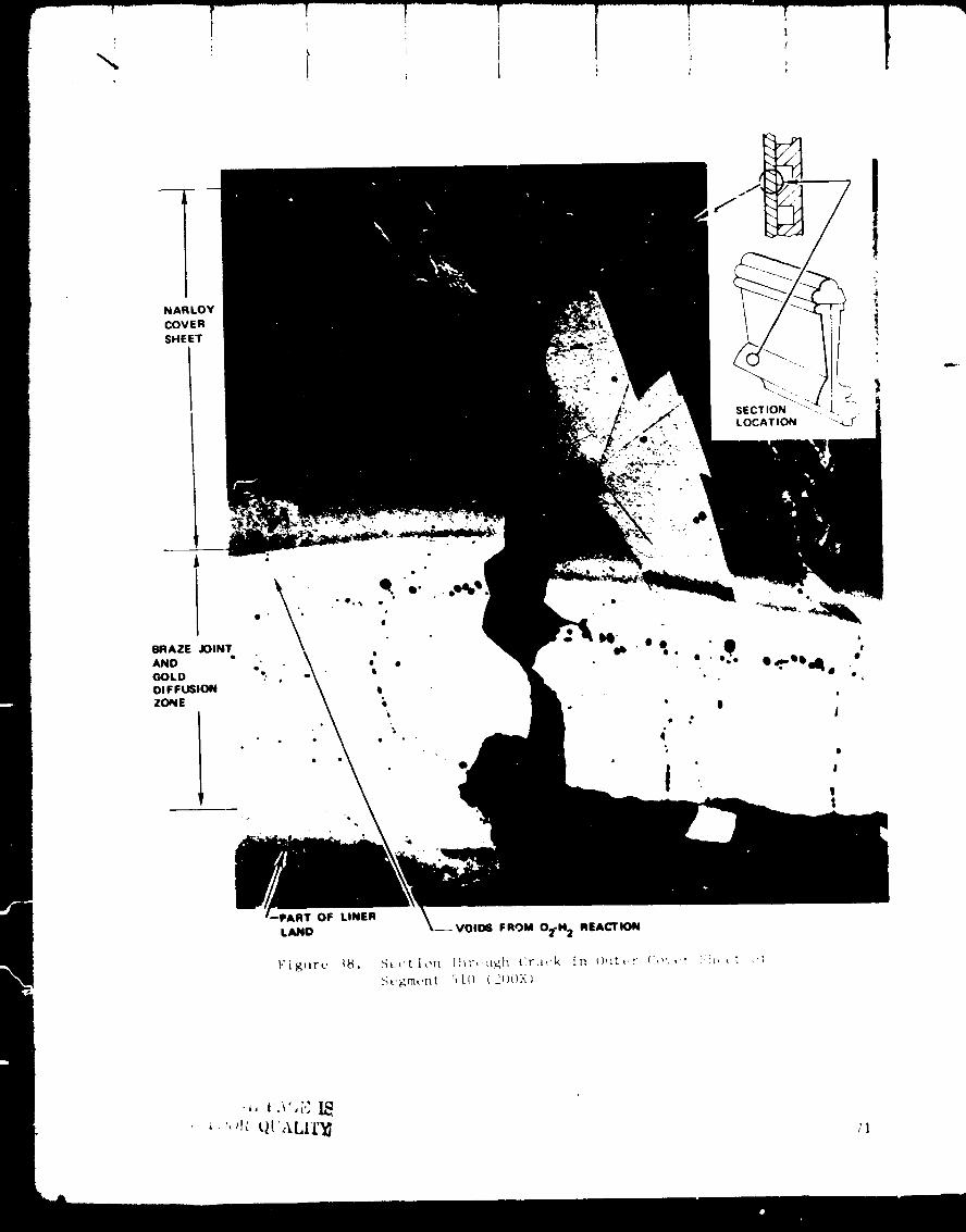
A sample of the coversheet and braze joint was removed from segment 510 in
the area where cracking had occurred (see Fig. 37 for a view of the crack
and Fig. 38 and 39 for photomicrographs of the cracked region). Samples
of NARIoy-A were also removed from several other combustor segments as the
investigation proceeded. All of the samples from useful combustors were
taken in a manner permitting replacement of the removed material. All
samples examined are listed in Table 7. Several Rocketdyne metallurgists
experienced in NARIoy-A and copper systems, and Dr. Martin Prager, a con-
sultant, reviewed the mounted sections and agreed that the chains of round
voids visible in the grain boundaries were definitely the result of a
reaction between hydrogen and oxygen, which formed steam.
The oxygen/hydrogen reaction in pure copper and copper alloys is wellknown through experience with OFHC copper. If the copper structure con-
t;iins oxides, or oxygen in solution, in a significant quantity (above
20 ppm), an H2/O 2 reafftlon will occur in H2 atmospheres above 593.3 C(1100 F). The diffustvity of hydrogen in copper is very rapid at these
69
N
Figure 37. Cover Sheet Crack in Outer Half of Segment510 Viewed From Cover Sheet Side (20X)
7O
NARLOY
COVER
SHEET
BRAZE JOINT
AND
GOLD
DIFFUSION
ZONE
t
• °
• °
RT OF LINER
LAND
;1
r-i
Ti
iI
.
72

t ---!-- _T " T
1 ' l ii
TABLE 7. _IETALLOGRAPtlIC INVESTI(;ATION OF SE(;NENTS
Segment Test: No. Loca t i on Rema rks
504
507
510
512
514
516
518
522
523
525
B
B
C
D
A
B
C
D
A
A
C
C
C
A-C
C
No Gasingf
No Gasing
No Gasing
Cracked-No Micro; Probably Gasing
Cracked - G.B.* Gasing
No Gasing
Light G.B. Gasing
No Gasing
Severe G.B. Gasing
Severe G.B. Gasing
Slight G.B. Gasing
Slight G.B. Gasing
No Gasing
No Gasing
No Gasing
*G.B. = Grain Boundary
tThe term gasing refers to voids formed by the O2-H 2reaction.
TEST LOCATIONS
7_
temperatu_tions are
ing it ensolution c
the presel
cal voids
boundarie_
of which
s_rength
The quest507R and !
was its sl
Analysis qcombustor
material]
trapped iidiffused
easily ew
ing GTA b
possible
The surfa
:es. Heavy sections are penetrated in a few minutes; light sec-
penetrated in seconds. When hydrogen is introduced during braz-
=ers the copper matrix and reacts with any oxides or oxygen in
,r in oxide form, forming bubbles of H20, steam_ Table 7 reportsLce of this reaction as "gaming". The steam bubbles cause spherl-
to fo1_ within the metal. The voids usually concentrate at grain
_. Severe H2/O2 reaction may even cause separation of grains,
rig. 53 is typical. The effect of the voids is to reduce the
md ductility of the material.
ion now was, how did the 0 2 come to be present in the NARIoy of
lOR; was it likely to be present in other combustors; and what
gnificance to the program?
_stablished several possible sources of oxygen in the NARIoy-A
segments: (I) the oxygen could have been present in the virgin
>rior to the fabrication of segments, (2) oxygen could have been
the braze joints during braze assembly or gold plating and
Lntc the NARloy-A during furnace operations, (3) NARIoy-A oxidizes
_n at room temperature, regardless of the cover gases used dur-
•_ 'ng and the cleaning operations between furnace cycles, it was
:hat oxides could have accumulated on cooling channel surfaces.
_e oxides could then have diffused into the NARIoy at elevated
temperatures during furnace operations. All of these possible sources
appeared a': first to be improbable, as the injurious effects of oxygen on
NARIoy had been well known all along, and guarded against in material
specifications, purchasing procedures, and processing procedures. Theactual methanism was determined by a process of elimination.
i!
The receiving records on the virgin NARIoy-A used in the combustors show
its oxygen content to be within specification, 20 ppm or less. The qualitycontrol steps required by specification on wrought NARIoy-A are shown in
Table 8.1 These procedures had been followed, providing considerable
confidence that incoming material was oxygen-free. Conceivably, however,
local oxygen pickup during forging or rolling could have been missed in
the oxygen check samples. As further confirmation of incoming material
quality, _ new braze sample was made from a gold-plated NARIoy-A cover-sheet from the same lot as the material used for the 24 combustors on the
thrust chamber. The sample was brazed in H 2 at 910 C (1670 F) and examined
metallographically. The results, shown in Fig. 40, showed no H2/O2 reac-
tion. There was also other evldence In samples taken from combustors that
the oxygen source was not the virgin material. In several cases where an
H2/O 2 reaction was presen', it was noted that both the coversheet and itsadjacent liner were contaminated. If the source of oxygen were local
pickup during forging or rolling, it is unlikely that adjacent areas of
coversheets and liners would both contain excess oxygen, since the liners
and coversheets were fabricated from different forgings. A good example of
this reasoning is seen in a section taken from segment 514 (Fig. 41).
Grain boundary H2/O 2 reaction is present in both the liner and the cover-
sheet. It might be argued that the original contamination was in the liner
74
!
i!
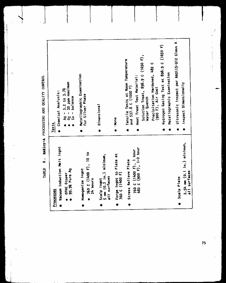
!
75
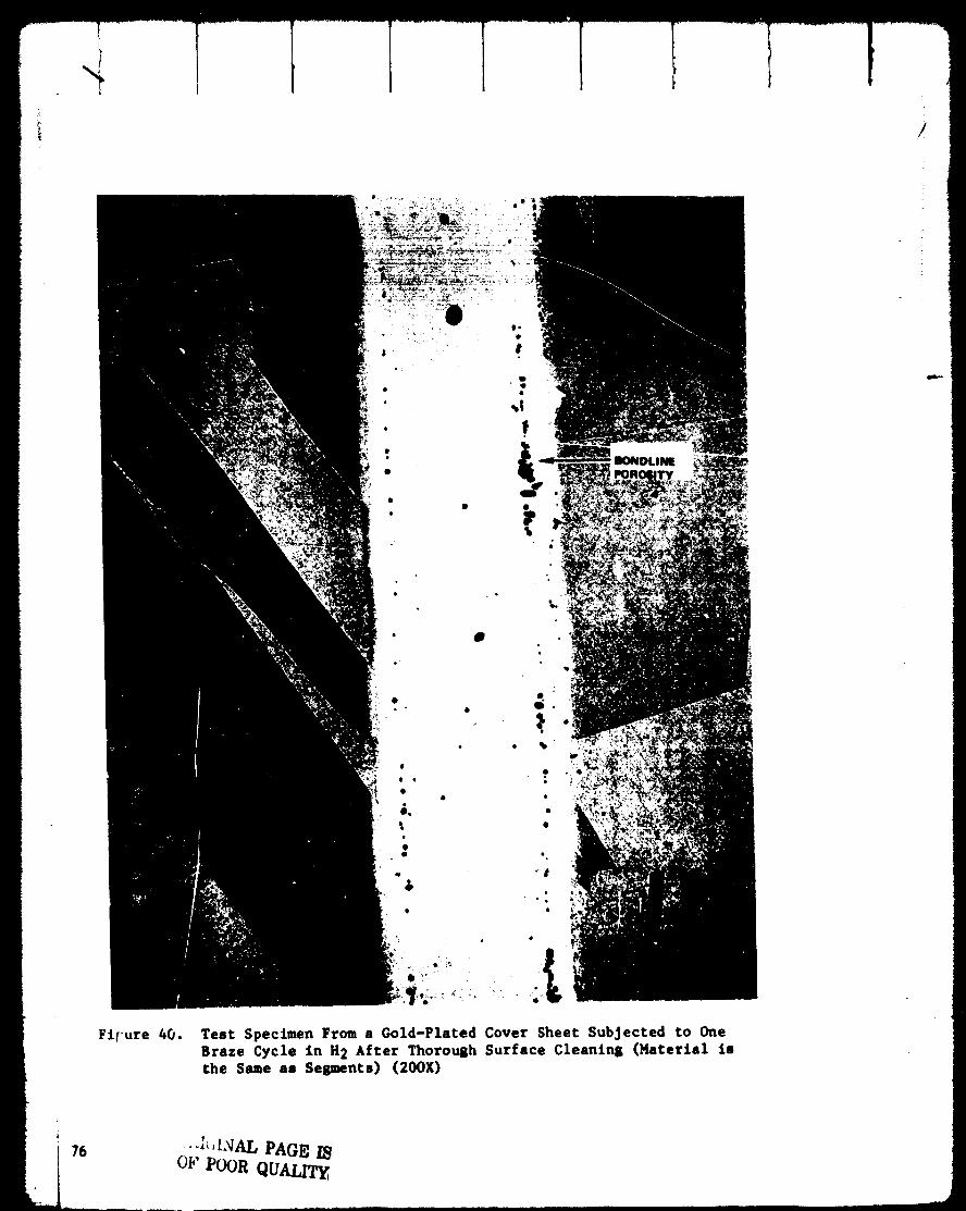
I
Fifure 40.
IlONDLINE
Test Specimen From a Gold-Plated Cover Sheet Subjected to OneBraze Cycle in H2 After Thoroush Surface Cleanlng (Fmcerlal isthe Same as Sesmencs) (20OX)
i 76oz."Poor QU_

COVER
SHEET
BRAZE
JOINT
VOI DS
FROM
02-H-REA_TION
LINER
LAND
LINER
HOT
GAS
WALL
Figure 41. Section From Outer Half of Segment 51:> Showing Severe
02-H 2 Reaction (IOOX)
t_, i'O01t C_UALII_ 77
only and diffused to the coversheet during furnace operations but, if so,
the H2/O2 reaction would be continuous across the braze joint between the
liner and coversheet reaction areas, which is not the case. Hence, it was
concluded that the virgin material could be eliminated as a major source
of oxygen.
In most of the sections taken from both segments and experimental samples,
porosity was noted in the braze joints. Thi_ is a common situation in
braze joints due to shrinkage or entrapped gases. Where the braze porosity
was oxygen from gases trapped in the joint surfaces at braze assembly, or
oxides remaining in the gold-NARloy-A plating bond line, it might be
assumed that these oxides could diffuse into the NARIoy-A parent metal
during thermal cycling and thus be the source of oxygen contamination.
Several observations on the sections d_sproved this assumption. If the
braze joint were the major source of oxygen, it would be expected that the
H2/O 2 reaction in the NARIoy would be worst near the braze joints, and this
was not generally true. Again, combustor 514 (Fig. 41) is a good example.
The worst grain boundary condition is in the liner some distance from the
braze joint and very little H2/O 2 reaction occurred near the braze joint.
In a section from combustor 516 (Fig. 42 and 43), isolated O2/H 2 reaction
was found in an area remote from a braze joint. There is also evidence
that at least part of the braze joint porosity is not the result of the
O2/H2 reaction. The section in Fig. 44 shows a centerline porosity and
traces of bond line porosity in the braze joint, yet this specimen was
never exposed to H2, so the porosity cannot be steam bubbles from the
O2/H 2 reaction. Additionally, a section from the inner half of segment
510 (Fig. 45) shows considerable bondline porosity in a braze joint with
no associated O2/H 2 reaction in the NARIoy. This segment was brazed in
hydrogen. The same is true of the specimen shown in Fig. 40.
Dr. Prager stated in his comments about the observed grain boundary condi-
tions that, in his experience, it is not possible to produce major amounts
of grain boundary weakening, such as seen in segment 514, from the amount
of oxygen available in a braze joint. The braze joint could contribute
some oxygen to the system, but not the quantity required _or the extensive
damage observed. It was therefore concluded that the braze joints were
not a significant source of oxygen.
The third possibility, diffusion of surface oxides into the NARIoy, was
found to fit the observed facts. A review of the fabrication history
of the segments brought out several significant points. The diagram in
Fig. 46 shows the fabrication sequence in regard to furnace and torch
brazing operations. GTA brazing (gas tungsten arc, with a heliarc torch
used as a heat source for brazing) with Nioro (82Au, 18Ni), an alloy which
brazes at 982.2 to i010 C (1800 to 1850 F),was performed on all segments
as a planned op_ratlon at two points in the sequence: the joining of mani-
fold shells to coversheet strips prior to furnace brazing the segment
halves together, and a reinforcement Nioro joint over the end plates after
furnace brazing the halves together. Since the segments were small, GTA
brazing temperatures were high, and NARIoy is an excellent thermal conduc-
tor, elevated temperatures were experienced in the NARIoy during GTA brazing.
78
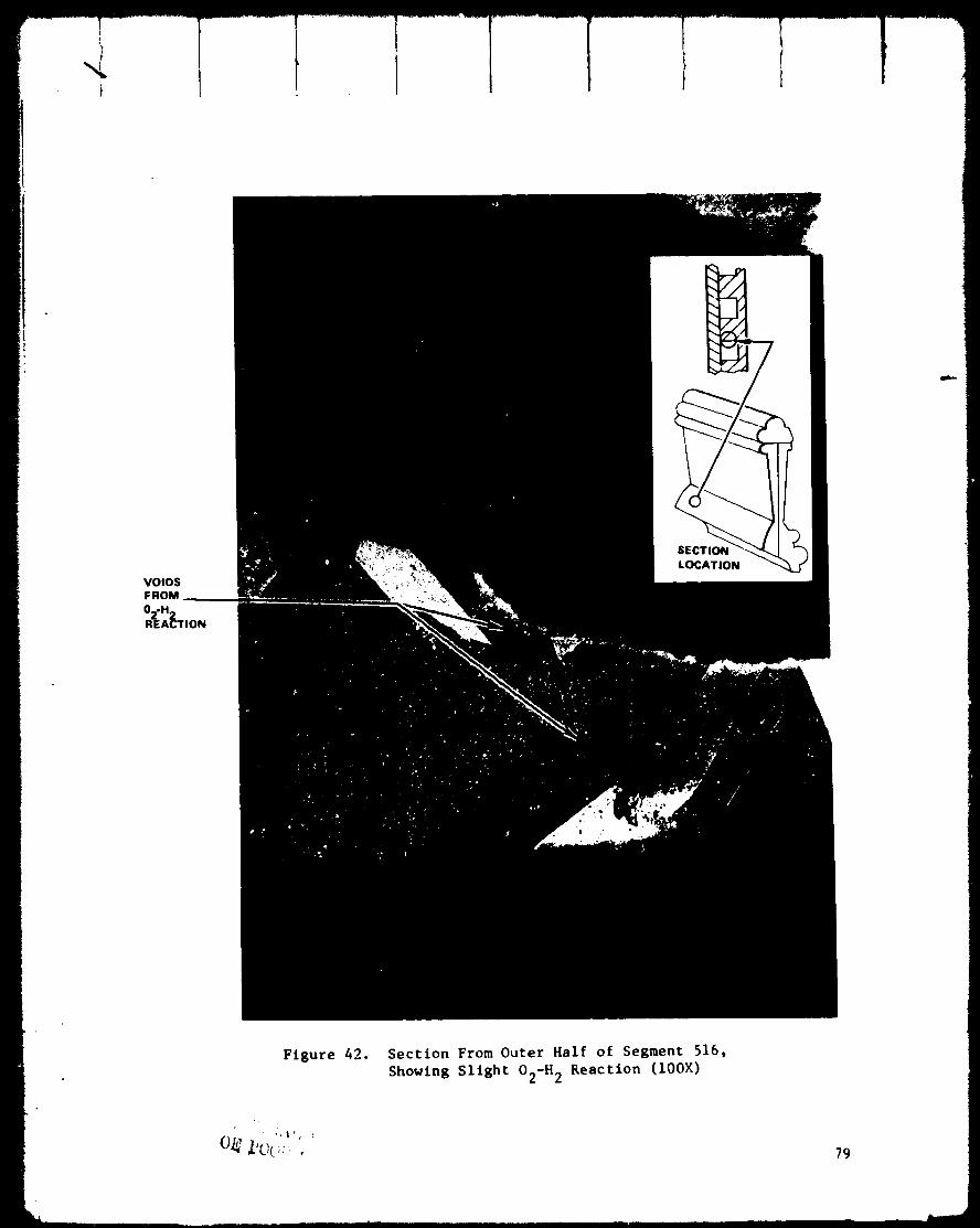
VOIDS
F ROM
02.H-REA_L'rlON
Figure 42. Section From Outer Half of Segment 516,
Showing Slight O2-H 2 Reaction (100X)
79

Figure 43. Section From Outer Half of Segment 516, Showing
Slight O2-H 2 Reaction (Blowup of Fig. 42) (400X)
8O

i
6
, o_ _'b, _.•. • ,%. • .-
n_._ ,oo...,'e ... •_, • ,.o. • ' _e "
BRAZE JOINT •
e
CENTERLINEPOROSITY
,I.!¢;jX.IL PAG/._ l_
, Ji.' V_JtJl_ QUALITY,
Figure 44. Test Specimen From NARIoy-A Cover Sheet, Furnaced Brazed
in Argon (No 02-H 2 Reaction Present; Centerllne Porosity
in Braze Joint) (i00X)
81
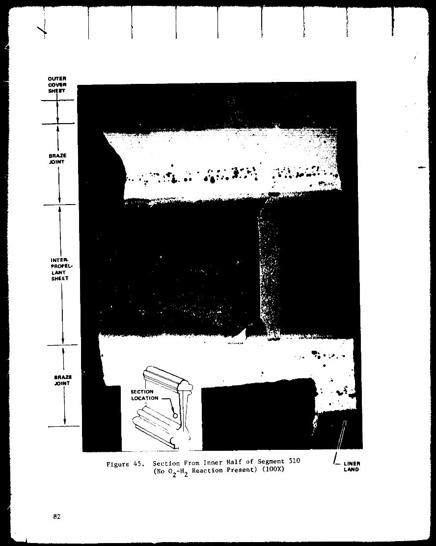
T
/
OUTER
COVER
SHEET
BRAZE
JOINT
"_'._." "'6"""• eeo'_e
INTEW
PROPE_
LANT
SHEET
BRAZE
JOINT
!Figure 45. Section From Inner Half of Segment 510
(No O2-H 2 Reaction Present) (IOOX)
/_ LINER
LAND
82
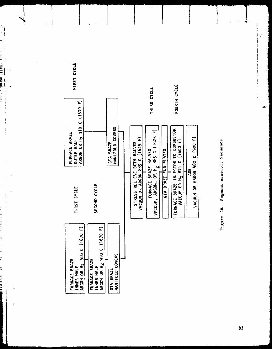
ILl..I
>"I.)
I"
e_m
1.1.
o
_D
v
(J
0
N
<,_ I.i.
hi "1" 0U
Zi,lO
o
Nt._
m
ww.j l._
I- z{/1 o• v, _.)
-:- _
o
N
lID .J
w-r- o
N i _,
_ tic Z _IC _ Z I_ u-
_1 "* Z (-.q:_ Z ,.v'
IJL Ir_I.tJ I._1_(_11.--I ',_DI'=C_I::Z: _'-d
"I-(..) II-"0 I.Pd
m I.IJ_Z,,,ol_ ¢.;11._1 n_'ila.I _:
_nO_n["X
f.n
1.1_.1u>.
2:I-.
N I
_D I
hi U I
-J<_1
N.._ I
i
(.,)Z
ZC.._
..In
Z
WN
,<F-
W..1
I.-N,
O
oI-"
nn 1.1.
OI--,--
uJ_
uJ(,_
z
I.i.
u.
oo
v
(_I
(,,Ico-,I"
I11(.._z
o
=E::)
L.)
=)
rj
;3"
.<
_6
//
83
External surface oxides formed during GTA brazing were removed by abrasive
cleaning prior to furnace brazing operations. The internal surfaces, i.e.,
cooling channels, were carefully flushed with inert gas during GTA brazing
to minimize oxidation. Use of inert cover gases is normally adequate pro-
tection against oxidation and was considered a reasonable precaution in
this case. In retrospect, however, scavenging of oxygen was probably
incomplete. The geometry, with square-ended channels and many leak paths
during manifol_ attachments, is difficult to purge completely.
All NARloy-A was chemically cleaned prior to the first braze cycle. On
subsequent cycles, early in the program, cleaning between braze cycles
was accomplished by degreasing. These cleaning steps had precedent in
other programs involving the brazing of copper alloys, such as brazing
of OFHC copper on F-1 injectors. During aerospike combustor fabrication,
however, channel contamination problems were experienced, specifically on
segments 512, 514, 516, and 518. Starting with segment 520, therefore,
chemical cleaning operations were added between braze cycles. Tne segments
with the added cleaning may have had less oxidation and correspondingly
less H2/O2 reaction, but this point cannot be verified nondestructively.
There were several possible sources of surface oxidation in addition to
GTA brazing. After furnace operations, assemblies were still warm when
removed f_om the inert furnace atmosphere. Rocketdyne process controls
required that NARIoy assemblies remain in an inert atmosphere on cooling
until the temperature was below 121 C (250 F). However, a NARIoy-A sur-
face oxidizes to some degree at ambient temperature and at a more rapid
rate abo_e 121 C (250 F), though the oxide laye_ is a thin, not a heavy
scale. Thus, the repeated furnace operations characteristic of the aero-
spike fabrication history may have contributed significant amounts of
oxygen. Perchloroethylene degreasing was used extensively to remove waxes
from combustor assemblies after machining operations, and the temperature
on removal from the degreaser was above 93 C (200 F). Hydraulic pressure
testing required vacuum oven drying to remove water from the segments,
and assemblies were normally above 93 C (200 F) when removed from the oven.
It is a fact that channel surface oxidation did occur, because channel
discoloration was observed in the specimens removed from segments 514 and
518, which contained complete sections of channels.
Experiments were then run to demonstrate that oxygen diffusion from an
oxide-coated surface can occur in normal furnace operations. Figures 47
and 48 show the results. The section in Fig. 47 and 48 was taken from a
specimen which was furnace brazed in argon for 30 minutes at 910 C (1670 F)
and then held in ar_on [or two bours at 871C (1600 F). It was removed
from the furnace and the surfaces were oxidized by heating in air with an
oxyacetylene torch unt_l the surfaces were black and slightly scaled.
The specimen was then returned to the furnace, and held at 871C (1600 F)
in argon for 120 minutes followed by 30 minutes in hydrogen at 871 C
(1600 F). The long hold time in argon approximated the multiple furnace
cycles on combustors _,hich were furnace repaired several times. Severe
84
i
!
I
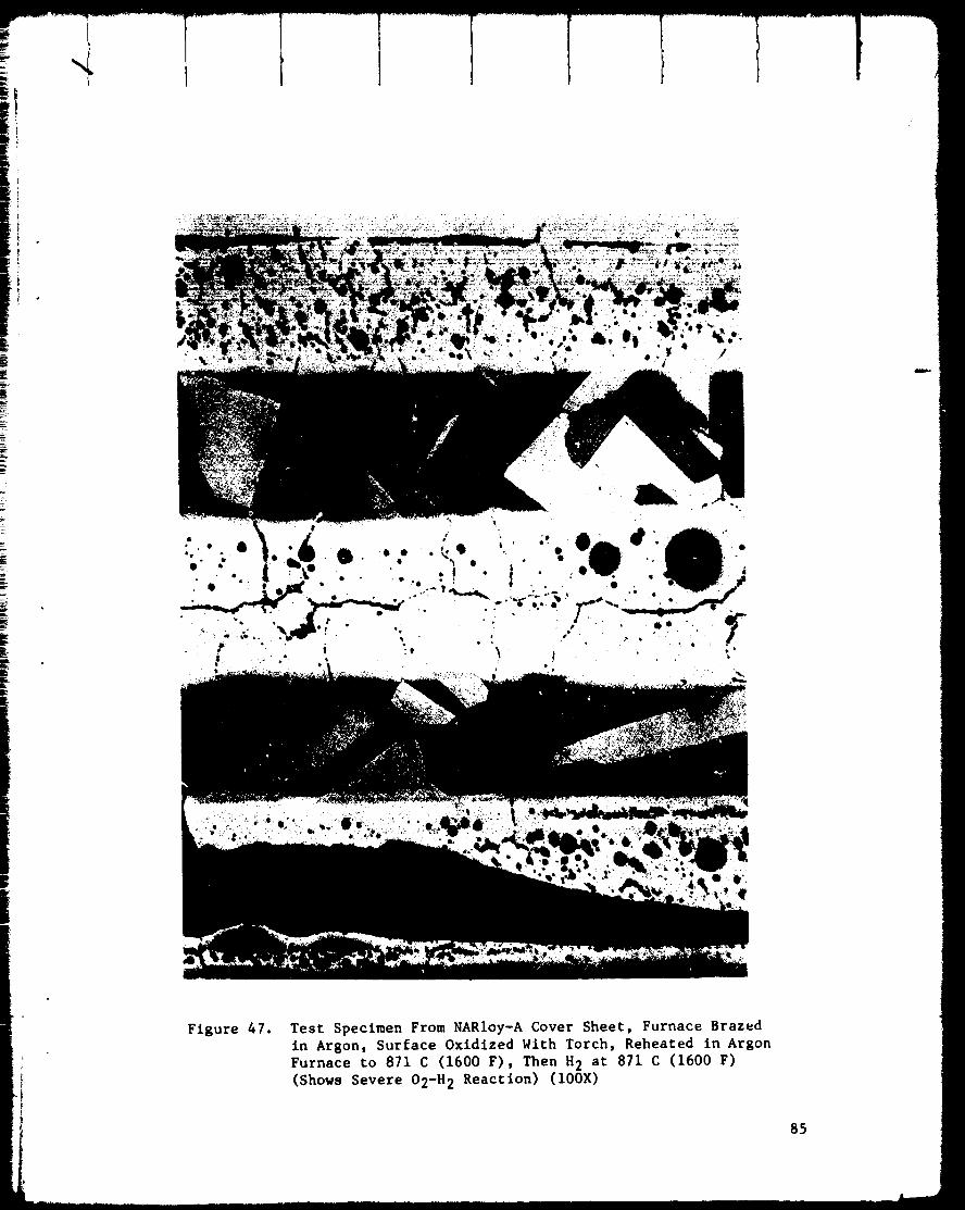
°1. ,_ °
Figure 47. Test Specimen From NARIoy-A Cover Sheet, Furnace Brazed
in Argon_ Surface Oxidized With Torch, Reheated in Argon
Furnace to 871 C (1600 F), Then H 2 at 871 C (1600 F)
(Shows Severe O2-H 2 Reaction) (100X)
85
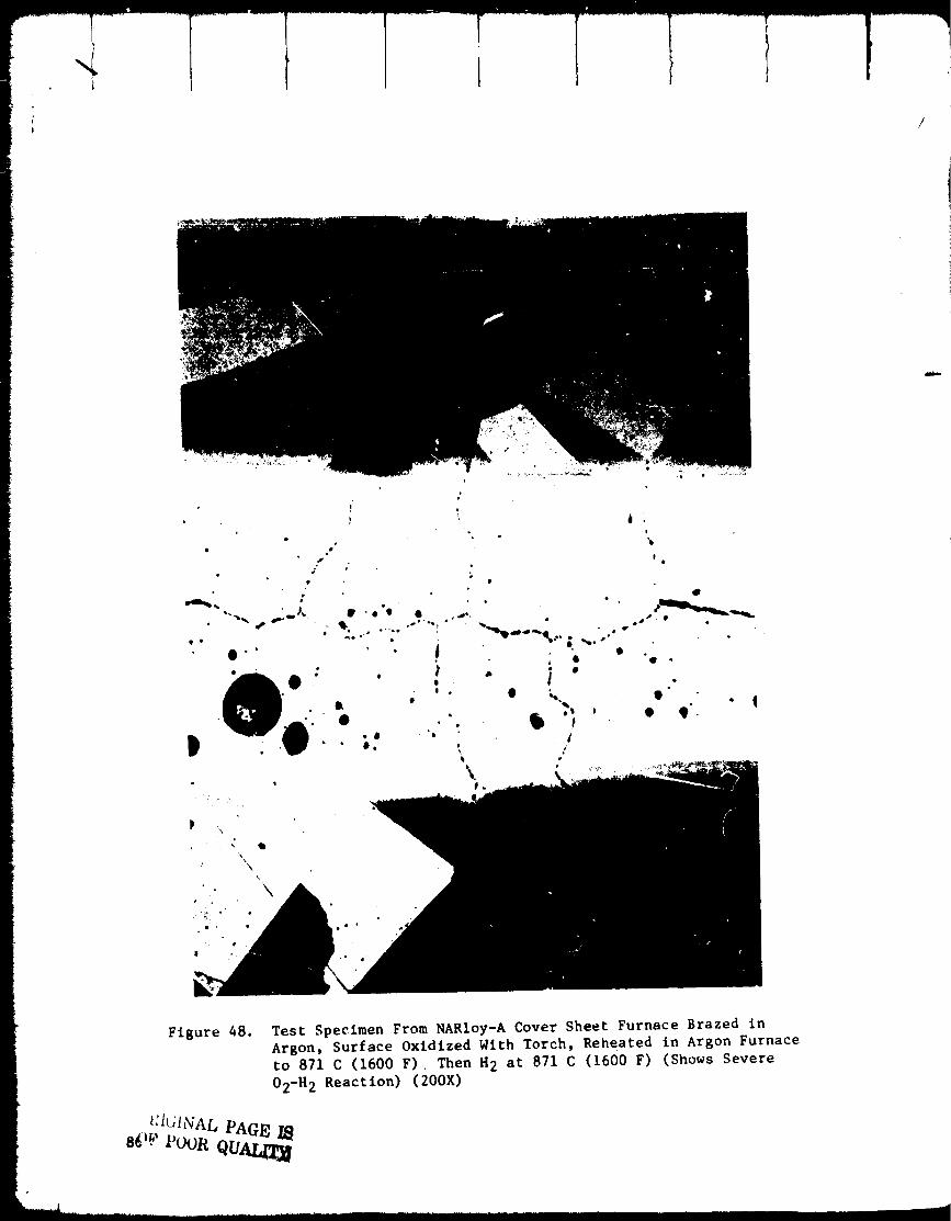
e
i •
0
e °
°_
! •
Figure 48. Test Specimen From NARIoy-A Cover Sheet Furnace Brazed in
Argon, Surface Oxidized With Torch, Reheated in Argon Furnace
to 871 C (1600 F)., Then H 2 at 871 C (1600 F) (Shows Severe
02-H 2 Reaction) (200X)
t:I61NAL PAGE IB
sO ._'Poor QUALrI_

H2102 reaction occurred, clearly indicating that surface oxides can be the
source of oxygen which diffuses into NARIoy and then reacts with H 2 when itis later introduced.
A second specimen was run without the long exposure to high temperature
in argon prior to hydrogen exposure. As oxygen diffusion rates are
relatively slow, there was some question about the capability to move
oxygen into the NARIoy in one hydrogen furnace operation. Safety require-
ments at Rocketdyne dictate that all hydrogen furnace operations employ an
argon atmosphere during heating. Hydrogen is introduced only above 760 C
(1400 F) furnace temperature. Because the braze tooling used for the com-
bustor segments was massive, the heating rates were slow; a typical brazing
cycle required 2-1/2 hours in argon from ambient temperature to 760 C
(1400 F) and another 1-1/2 hours in hydrogen to the brazing temperature of
871 to 910 C (1600 to 1670 F). The heating interval in argon might provide
the time necessary for oxygen diffusion, while the H2/O 2 reaction could
take place in the subsequent H 2 portion of the cycle. The test specimen
was first brazed in hydrogen at 910 C (1670 F) in the normal manner. It
was then surface oxidized in air with an oxlacetlene torch until it was
discolored but not scaled. The furnace cycle following oxidation was a
typical hydrogen braze cycle, duplicating the times in the preceding text.
The H2/O 2 reaction occurred, proving that there is sufficient 02 diffusion
during heating in argon up to 760 C (1400 F) to provide the damaging oxygen
in one hydrogen furnace cycle. The results" are shown in Fig. 49.
With the mechanism established, it was now possible to reconstruct the
fabrication situations which caused the NARIoy cracking. Looking at the
sequence in Fig. 46, it can be seen that there was no source of surface
oxidation in the first two braze cycles, as all NARloy parts were chemi-
cally cleaned before the first braze cycle, and the operations between
the first and second braze cycle consisted only of mechanical assembly
in a clean area. There were no elevated temperature operations and thus
L_o forelg_L materials introduced at that time. The first opportunity for
surface oxidation and diffusion of v;_gen into the NARIoy-A was the GTA
brazing of manlfo]d covers, followed by a stress relief in vacuum or argon,
which occurred immediately before the third braze cycle (the joining of
the two combustor halves). The stress relief at 885 C (1625 F) provided
ample opportunity to drive oxygen into the NARIoy.
Either hydrogen or vacuum brazing was used for the third and fourth cycle
depending on equipment avail_bility. Subsequent repair cyclesalso used
various atmospheres (hydrogen, argon, or vacuum) so the sequence of atmos-
pheres was not the same for all segments. Regardless of the exact sequence;
however, exposure to hydrogen on the third braze cycle r r any cycle there-
after appears likely to have caused an H2/O p reaction itt the NARIoy-A. Areview of the furnace records showed that all combustors except six were
brazed in hydrogen at some time after the second braze cycle. Table 9
lists the furnace information by combustor segment number, together with
an estimate of the probability of the presence of the H2/O 2 reaction.
87

)
88
XO
Oro-
Ll."1"
OL)
,,.O O
vLI.I
U ZILl
O>-
c,I (,J"r_
>-_ X
NO
_ N
Z _
_ X
"d
,l
..J
0
a.
OO
la.I .._"
>-
la.ION',.O
"¢_0I'--
,_uJ
_ Z0
_tL..J
0I--- C.}
I.LI (:_
Wl-.
,l.J ,r"l
0
X
•_-¢ r,.D
U
OC_l._
I Uc_c_
g _0 0
0 m
m _'_ 0
Ov
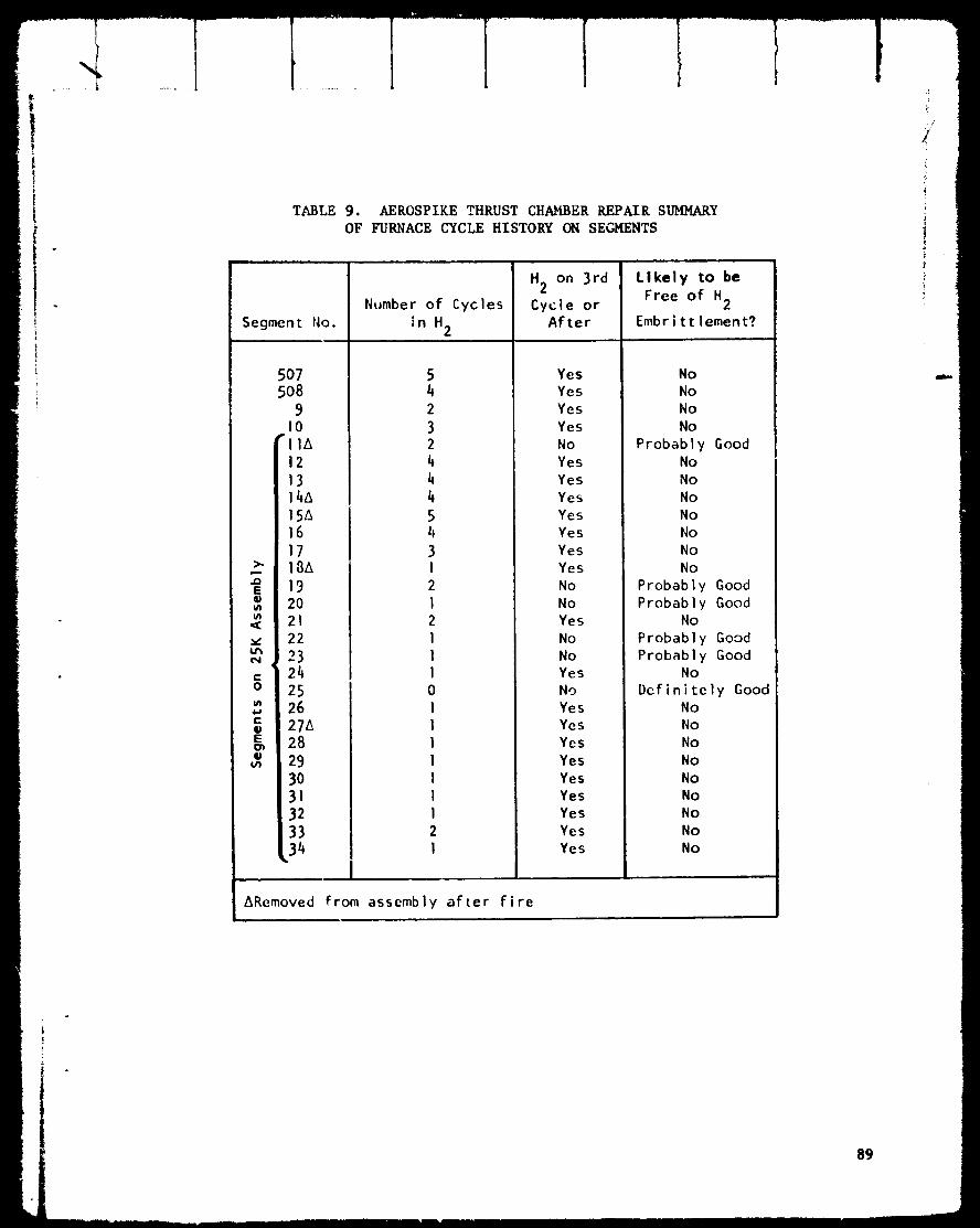
TABLE 9. AEROSPIKE THRUST CHAMBER REPAIR SUMMARY
OF FURNACE CYCLE HISTORY ON SEGMENTS
Segment No.
>,.
..oE
v.
¢',I
c-O
g_
r-
E
5O7508
9I0
"IIA
12
13
15A161718A
19
2O21
22
23' 24
252627_28
293031
, 32
Number of Cycles
in H2
542
32
4
4
4
54
3I
2
I
2
l
l
l
0
I
l
I
I
l
l
I
2
I
H 2 on 3rd
Cycle or
After
Yes
Yes
Yes
Yes
No
Yes
Yes
Yes
Yes
Yes
Yes
Yes
No
No
Yes
No
No
Yes
No
YesYes
Yes
Yes
YesYes
Yes
Yes
Yes
Likely to be
Free of H2
Embrittlement?
No
No
No
No
Probably Good
No
No
No
No
No
No
No
Probably Good
Probably Good
No
Probably Good
Probably Good
No
Definitely GoodNo
No
No
No
No
No
No
No
No
_Removed From assembly after fire
89

It was important for program reasons to determine how many of the segments
exposed to hydrogen were affected by the hydrogen/oxygen reaction. A
metallographic sampling plan was devised for this purpose. Segments 507
and 510, with known cracks, were sampled in multiple locations, and several
other segments were sampled in one location each from the outer coversheet
and liner. The results are listed in Table 7 and photomicrographs not
already displayed are presented in Fig. 50 through 59. Segment 507 had
extensive cracking on the inner liner's oxidizer coversheet, yet samples
from the outer liner showed no O2/H2 reaction. The reverse was true of
segment 510; cracks were found near both aft end edges of the outer cover-
sheet, but a sample from the inner coversheet and liner showed no H2/O 2
reaction. This evidence indicated that the varying fabrication histories
of individual segments resulted In unpredictable local H2/O 2 reaction
areas which cannot be detected by any simple sampling technique. However,
the sampling results of Table 7 agree fairly well with the furnace records
of Table 9, i.e., the segments exposed to a hydrogen brazing atmosphere
after the second cycle all showed some evidence of H2/O 2 reaction (segment
518 may be an exception), and the segments not exposed to hydrogen had no
reaction. The overall conclusion with regard to usability of segments
was that no reliable metallographic sampling plan is possible to prove that
no H2/O2 reaction has occurred. All segments exposed to hydrogen after
the second braze cycle must be assumed to have some areas of reduced
ductility due to the H2/O2 reaction.
The NAK_oy-A cracking investigation resulted in the termination of the pro-
gram. Of the 19 remaining combustors on the thrust chamber assembly, only
5 could be counted upon to be free of the reduced strength and ductility
caused by the presence of the H2/O2 reaction. Of the five combustors in
work for replacements, only one was sure to be free of the reaction.
Experience during the repair effort on 507R and 510R had demonstrated
that the presence of the chains of voids caused by the 02/H 2 reaction
could result in cracking during cryogenic cycling. Such cycling was an
inescapable part of the planned test program, so the risk of cracks and
test stand fires if the existing combustors were used was too great
to permit program continuation.
i9O
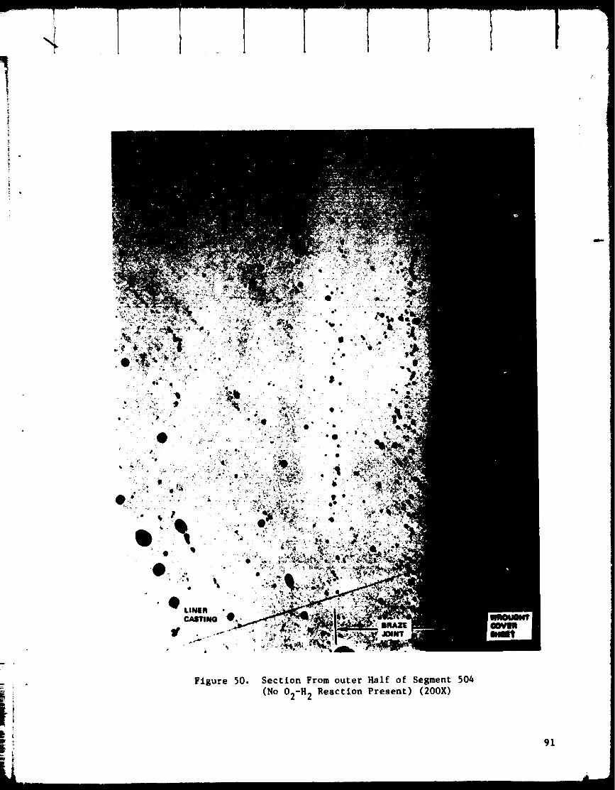
Figure 50. Section From outer Half of Segment 504
(No O2-H 2 Reaction Present) (200X)
91
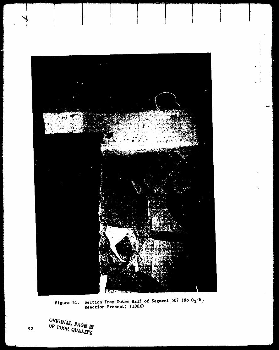
}
Figure 51. Section From Outer Half of Sepent. 507 (No O2-_ ?Reaction Present) (100X)
92
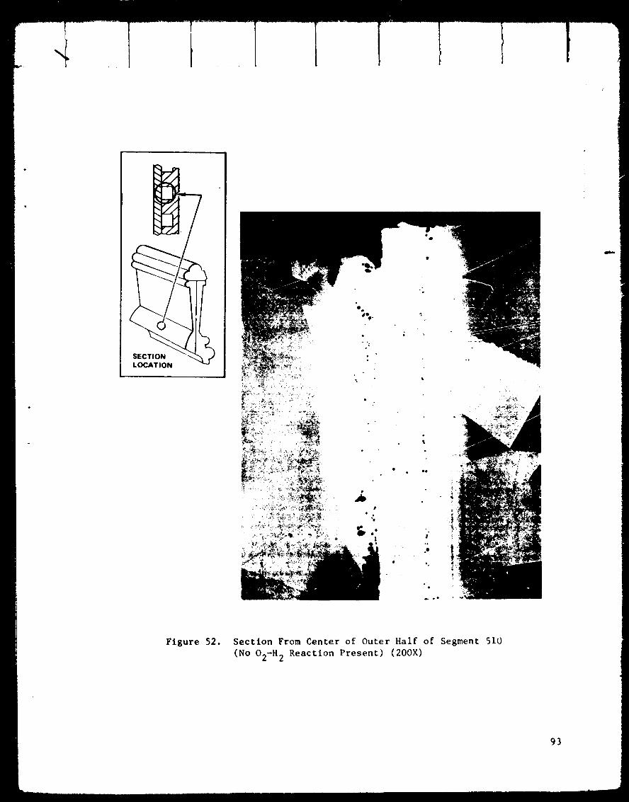
_J
• ee
t°
.,
.O
Figure 52. Section From Center of Outer Half of Segment 510
(No O2-H 2 Reaction Present) (200X)
93
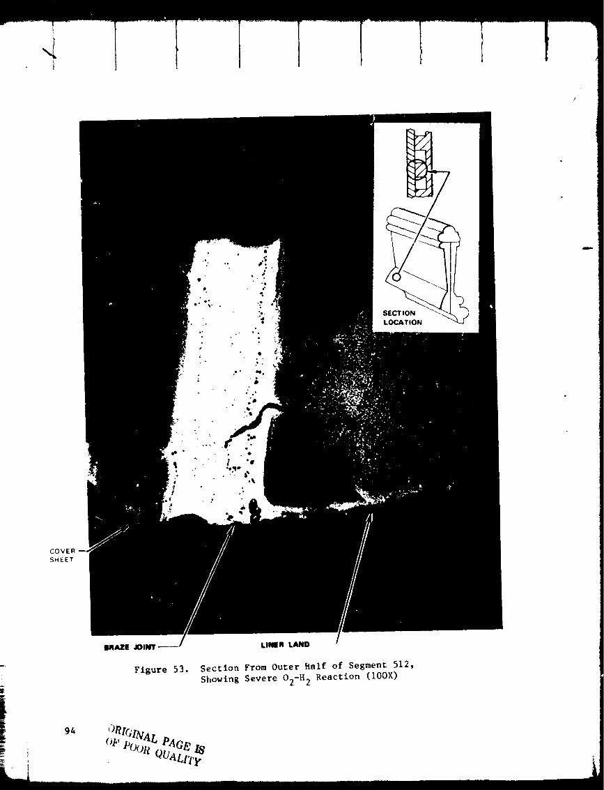
COVER
SHEET
LINER LAND
Sectlon From Outer Ralf of Segment 512,
Showing Severe O2-H 2 Reaction (lOOX)
94
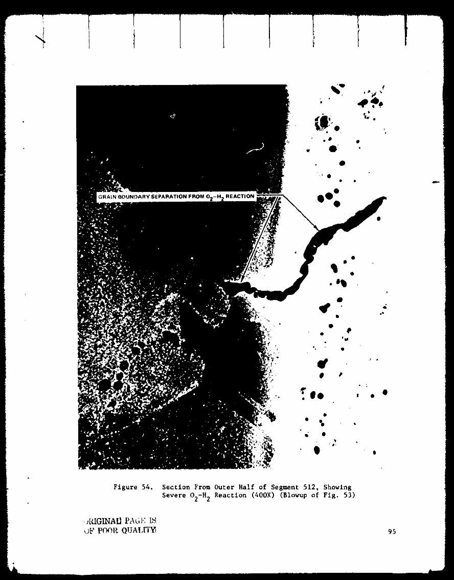
I
GRAIN BOUNDARY SEPARATION FROM O2-H 2 REACTION
o
Figure 54. Section From Outer Half of Segment 512, Showing
Severe O2-H 2 Reaction (40OX) (Blowup of Fig. 53)
. JRIGI/qAI.I PAC, J,_ IS
_;b' POOR QUAT,FI'_ 95
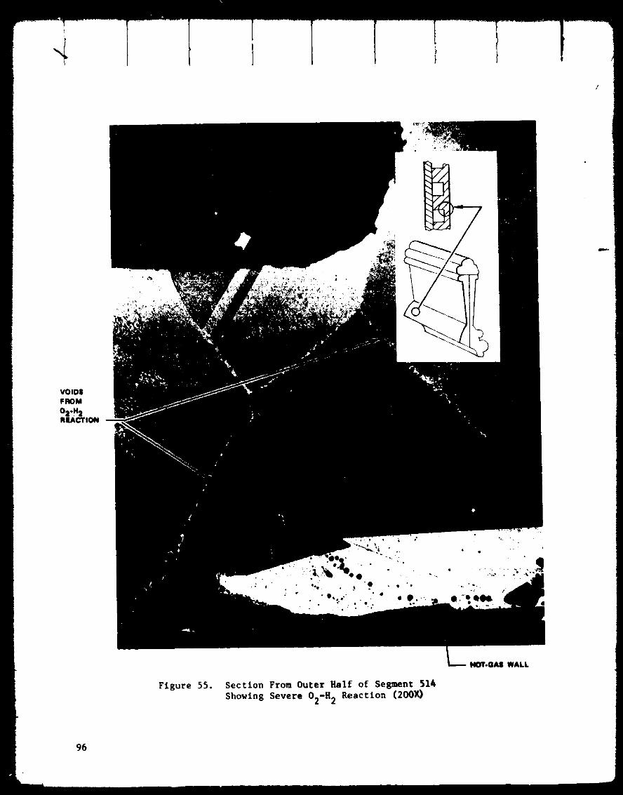
F
VOIDS
FROM
%-%REACTION
Figure 55. Section From Outer Half of Segment 514
Showing Severe O2-H 2 Reaction (200X)
HOT.GAS WALL
96
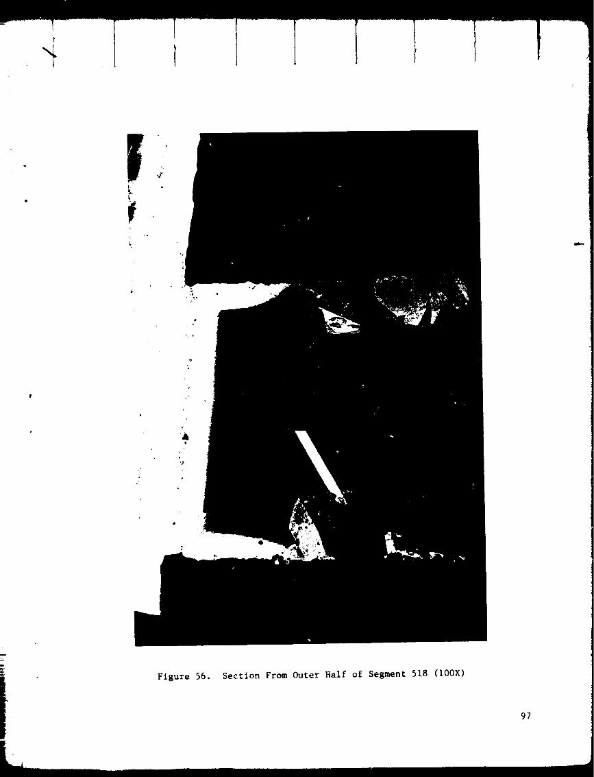
Figure 56. Section From Outer Half of Segment 518 (100X)
97

/
Figure 57. Section From Outer Half of Segment 522 [No O2-H 2 Reaction
Present; Same Location on Combustor as Fig. 42 (100X% The
Large Section to the Right of the Braze Joint is From the
Liner Land_
98
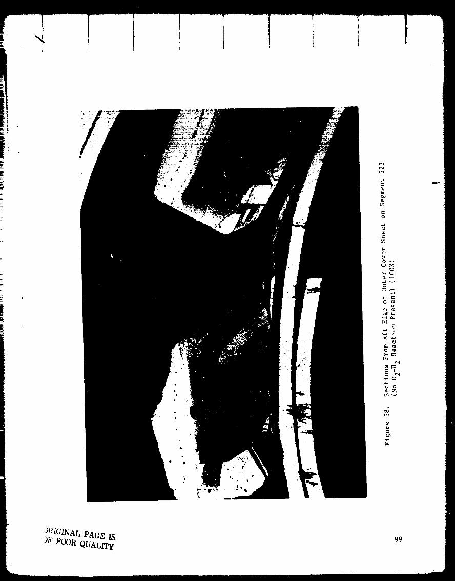
¢',4t_
4..J
o
:>of-_
oo
o
,_ o
o ¢_
o•,.-i 0
o_Z
u_
ORIGINAL PAGE IS-gF POOR QUALIT_
99
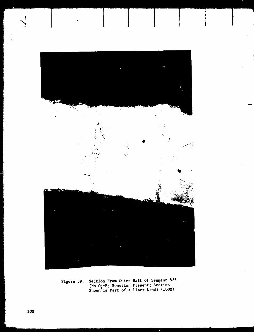
\
!
Q
Figure 59. Section From Outer Half of Segment 525
(No 02-H 2 Reaction Present; SectionShown is Part of a Liner Land) (100X)
100

suffered by the nozzle tubes is shown in Fig. 60. The pattern of tube
damage is catalogued and shown in Fig. 61. Basic tube r_pair techniques
were partially developed during CFY 75. Two methods of repair were applied,
the saddle-patch repair and the inserted tube repair. Figure 62 describes
the two methods in sketch form. For the saddle-patch approach, a nickel
sheet of 0.2 to 0.25-mm (0.008 to 0.010 inch) thickness is used. Each
saddle-patch is formed to the contour of the tube and is brazed to the tube
with an oxyacetlylene minitorch, using EASY-FLO No. 3 braze alloy. The
tube insertion repair method requires grit blasting to clear the oxides
from the inner surface of the tubes and also to clear the zirconium oxide
from the outer hot gas surface of the tubes. The damaged area is then
cut out (like a window), and the tube ends are cleaned and deburred. New
tapered tubes are inserted, in place with a 1.02 to 1.52-mm (0.040 to
0.060 inch) overlap at each end. Nickel shims are wedged between each
tube to fill the gaps, then 'flux is applied and the tubes are brazed in
place, again using the o×yacetyline mlnitorch and the EASY-FLO No. 3 braze
alloy.
Experience early in the repair development activities brought out one of
the limits of the saddle-patch repair technique. From this series of tests,
101

c_
!L_r_
c_f_
c_
I
E
t_
oZ
c_
L,
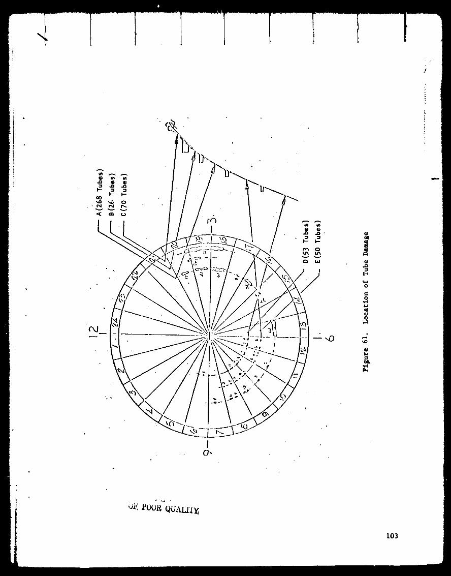
/
/
I
|
0
0
a.Jqoo
pJ
_o
1.4
IO,
Ok: YOOR QU&IAI'E
103

0
/
104
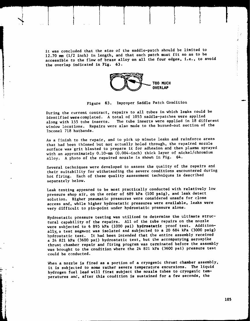
it was concluded that the size of the saddle-patch should be limited to
12.70 mm (1/2 inch) in length, and that each patch must fit so as to be
accessible to the flow of braze alloy on all the four edges, i.e., to avoid
the overlap indicated in Fig. 63.
TOO MUCH
OVERLAP
Figure 63. Improper Saddle Patch Condition
During the current contract, repairs to all tubes in which leaks could be
identified werecompleted. A total of 1053 saddle-patches were applied
along with 155 tube inserts. The tube inserts were applied in 18 different
window locations. Repairs were also made to the burned-out section of the
Inconel 718 hatbands.
As a finish to the repair, and to pick up minute leaks and reinforce areas
that had been thinned but not actually holed through, the repaired nozzle
surface wasgrlt blasted to prepare it for adhesion and then plasma sprayed
with an approximately O.10-n=n (O.004-inch) thick layer of nickel/chromium
alloy. A photo of the repaired nozzle is shown in Fig. 64.
Several techniques were developed to assess the quality of the repairs and
their suitability for withstanding the severe conditions encountered during
hot firing. Each of these quality assessment techniques is described
separately below.
Leak testing appeared to be most practically conducted with relatively low
pressure shop alr, on the order of 689 kPa (i00 pslg), and leak detect
solution. Higher pneumatic pressures were considered unsafe for close
access and, while higher hydrostatic pressures were available, leaks were
very difficult to pin-point under hydrostatic pressure alone.
Hydrostatic pressure testing was utilized to determine the ultimate struc-
tural capability of the repairs. All of the tube repairs on the nozzle
were subjected to 6 895 kPa (1000 psi) hydrostatic proof test. Addition-
all_ a test segment was isolated and subjected to a 20 684 kPa (3000 pslg)
hydrostatic test. It had been intended that the entire assembly received
a 24 821 kPa (3600 psi) hydrostatic test, but the accompanying aerospike
thrust chamber repair and firing program was terminated before the assembly
was brought to the condition where the 24 821 kPa (3600 psi) pressure test
could be conducted.
When a nozzle is fired as a portion of a cryogenic thrust chamber assembly,
it is subjected to some rather severe temperature excursions. The liquid
hydrogen fuel lead will first subject the nozzle tubes to cryogenic tem-
peratures and, after this condition is sustained for a few seconds, the
105

r_I
_D
I
N0
Z
_O
106

!J
i "
oxygen will be admitted to the combustor and will rapidly bring the hydrogen
coolant to well above ambient temperature. During cutoff, there will be a
fuel lag which will again subject the nozzle to cryogenic temperatures.
This duty cycle raises a question as to whether the type of nozzle repairs
being developed here would be degraded by rapid temperature excursions.Checkout tests were therefore conducted to evaluate this effect. Liquid
nitrogen was flowed through the nozzle inlet manifold for sufficient time
so that liquid nitrogen was seen to leave the nozzle aft collection
manifold. When liquid flow had been established, the feed was cut off and
the nozzle permitted to warm up to ambient temperature. This procedure was
repeated three times. Leak testing was then conducted after the cryogenicshock excursion and indicated that all repairs had come through the procedure
without damage, except for one of the locations where the tube insert type
of repair had been utilized. For this tube insert patched area, there had
apparently been insufficient braze penetration between the inserted tube
and the parent tube so that the inserted tubes pulled loose, and small leaks
ensued. Additional braze was applied to this area and the defect corrected.
Cryogenic shock testing is thus established as a useful technique for
evaluation of tubular nozzle repairs.
Both of the repair techniques under development involved the application of
braze alloy to the tube and patch and, therefore, they present some risk
that "dropthrough" of the alloy will significantly increase the resistance
of the tube to the cooling hydrogen flow. Because of this possible hazard,
each of the repaired tubes was flow checked utilizing the technique
illustrated in Fig. 65. Additionally, a representative sample of tubes
that had not required repair were flow checked to establish a base condi-
tion. In utilizing this technique, one relies upon the condition that the
static pressure at each tube exit is very close to atmospheric, and that
all the tube exit areas are nearly equal. The square root of the total
pressure measurement detected by the impact tube is therefore an indicator
of the relative weight rate flow of air through the tube being probed. The
air pressures throughout the nozzle system are all low, on the order of
14 kPa (2 psig), so that there is no possibility of choking in any location.
In this respect, the flow conditions are consistent with those existing in
a hydrogen-cooled nozzle, and the flow distribution in the test setup will
closely simulate the firing condition. By the method described, it was
possible to estimate the average flow through all the tubes in the nozzle
and then, by comparison, to evaluate the reduction in the flow of those
repaired tubes whose resistance had been affected by the repair activity.The results of this air flow check indicated that the tube repair techni-
ques did not result generally in a gross reduction of flow in the repaired
tubes as compared to the unrepaired tubes. This c_n be seen in the plot
of Fig. 66 for the nozzle tubes in llne with one of the 24 aerospike com-
bustors. The unrepaired tubes are identified with a black dot. However, a
number of repaired tubes did show a significant flow reduction so that it
was necessary to establish a criterion for acceptability and to rework
those tubes whose flow fell below this criterion. For this particular
nozzle, it was possible to establish the criterion that no tube would be
107
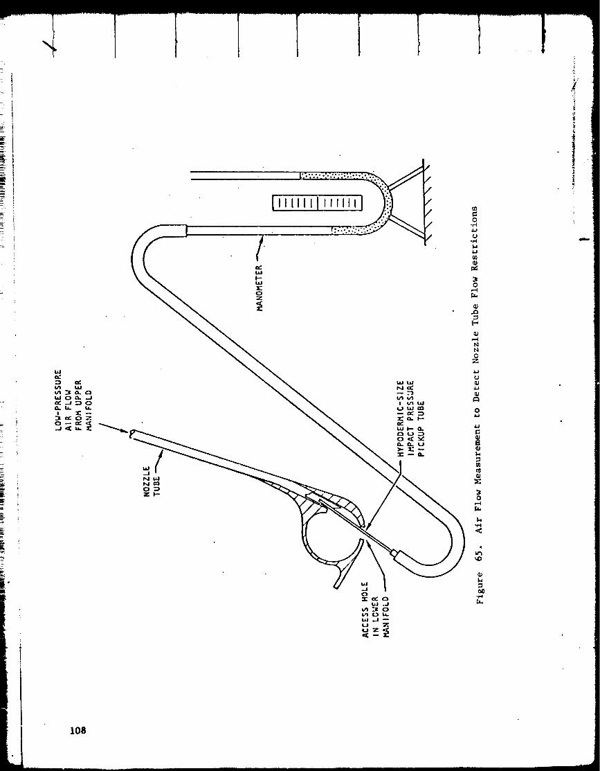
_O
_Oz
O.,-I4.1CJ
Q;
O
Q;
Q;
NNOZ
_J
4.1
o
4-;
Q;a
Q;
O
<
i!
108

•i /
i
o
i
4-)
jD
NN
0
Z
q_
o
cJ
J_
0
II
c;
p_
_D
109
accepted whose flow was less than 65% of the average flow in all the tubes.
The acceptable flowrate was based on the calculated heat transfer condi-
tions and stresses projected for operation. Twelve of the repaired tubes
were reworked to meet the criterion.
Quality evaluation via X-ray was also found to provide useful information.
The braze alloy placement is readily determined in that the braze alloy is
seen on the X-rays as a light area. X-rays permit evaluation of the
adhesion of saddle-patches and the degree of overlap, and braze penetration
into the joints of tube insert repairs.
11o

/
CHAMBER SUFPORT STRUCTURE
BAC_'.UP RINGS
The 24 combustors, and the aerospike nozzle to which they are attached,
are supported by being sandwiched between titanium rings that serve to
position the combustors correctly on the nozzle. The rings accept the
thrust generated by the combustors and the nozzle and transmit that thrust
to a central gimbal bearing. The inner ring of this two-ring assembly
was so seriously damaged during the fire that had terminated the previous
test program that the ring had to be replaced rather than repaired. It
had already been demonstrated on the previous contract that a sufficiently
lightweight construction for this ring could be designed and fabricated,
so it was decided on this contract that the replacement ring would not
exactly duplicate the previous design. It omitted some of the intricate
but weight-saving machining that tends to add materially to cost and sched-
ule time. A new design, No. RSO03737X, was made to define the configura-
tion of the new inner backup ring. A copy of the drawing is incorporated
in Fig. 67 of this report. A titanium forging from which this ring could
be machined was available from the previous program. A five-axis, numeri-
cally controlled milling machine was utilized for machining the lightening
holes, and a VTL tracer lathe was used for the external contour. A photo
of the completed ring is shown in Fig. 68.
The outer backup ring was to be repaired by weld buildup of the location
showing minor burn damage and by welding in a segment to replace the one
area that suffered major burn damage. Photos of the outer backup ring
showing the areas that sustained damage during the test stand fire are pre-
sented _n Fig. 69 and 70. A fabrication experiment was conducted in which
samples of titanium backup rings obtained from existing ring segments were
welded in a controlled atmosphere box (argon), under conditions duplicating
as closely as possible the physical conditions that would exist when repairs
were made to the actual backup ring. The weld samples were then sectioned
and subjected to tensile testing. Section examination and tensile tests
showed that the weld properties were well above the minimums required for
adequate strength in the locations to be welded on the actual backup ring.
Drawing RSO05833X, which is presented in this report as Fig. 71, was then
released to define the backup ring repair procedure. Repair effort on the
actual outer backup ring was never carried out because fabrication effort
was stopped by the combustor problem.
THRUST CONE AND SUPPORT STRUTS
The structure that carries the thrust from tile inner backup ring to the
gimbal bearing is illustrated in Fig. 27. As can be seen, a number of
titanium struts carry the load in tension from the backup ring to the base
of the thrust cone, and the cone carries the thrust in compression up to
the gimbal bearing. All of these parts were somewhat affected by the fire
that had o_:curred on the previous test. All parts were carefully cleaned
and examined. Decisions were made on which parts could be refurbished and

'.......... _ ! ! ! ____..__k___._
•___.__.'_. _ -_ _-_-,p:-.040 _ ._n_ rc
/
_ILL
o, _
z_40
s_c_o. C-C. nn,_re44_clrdl
r/'_ "
,_,,,__ / ,_o_,
wow D-D
L.-_-;.__!
I_ _"'_'_ '_,, " "V
.. aZ__.,"/._ -'.iii"--/
•_s '_e.._" ".
D_
:J3
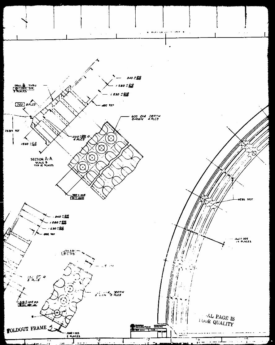
I !• u,tml ,|m _o,_ 6.. latJ •
I4
iII
/
mw
ir_
/
r_
,/:1 ,
,lf
"N'
ItE._
:7
/
L'/-
o_
I
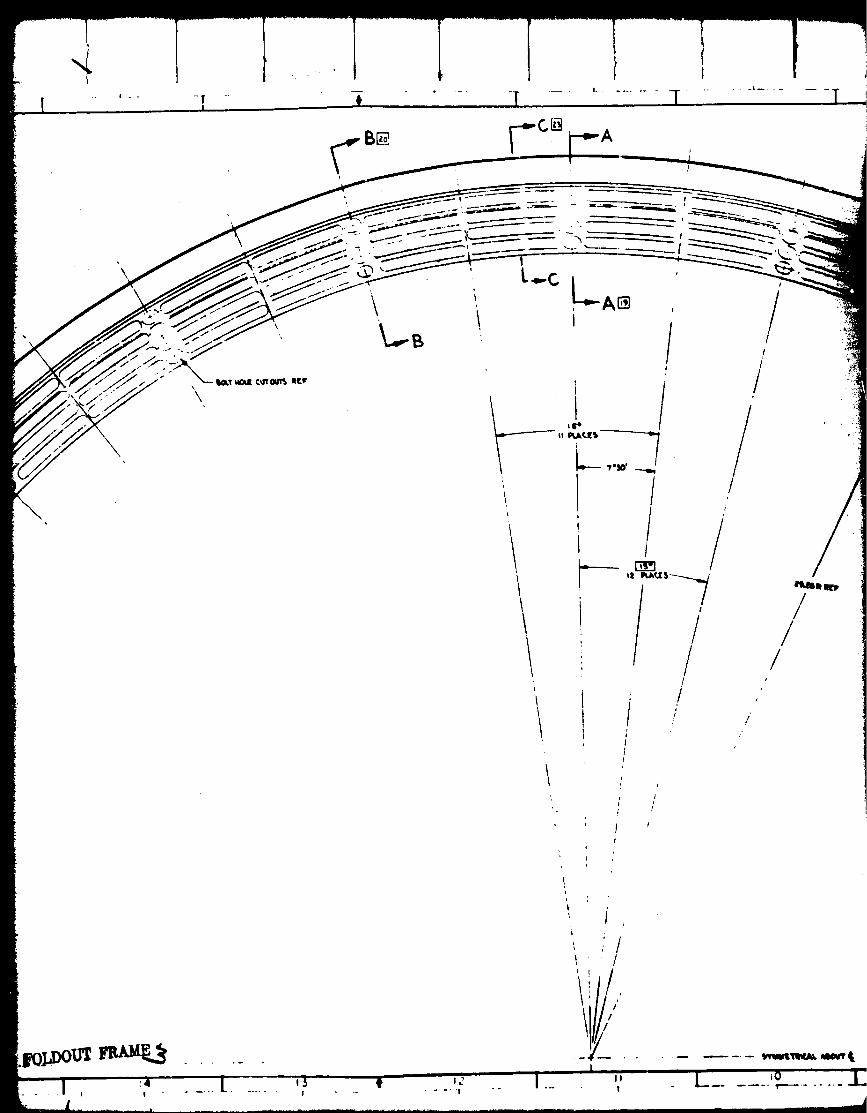
-[I
\
"i
\
'\
, L-.C L...A_ ,\ ,
'1 1
t
I
f
/
/j,
/'iI P_rJ[ $ _17t/ /
/I
//
/
Iit
I
J
/
• ltlBm _
//
//
I ! "
!
1 "- ..... |
j,;/
/
_1" .
II
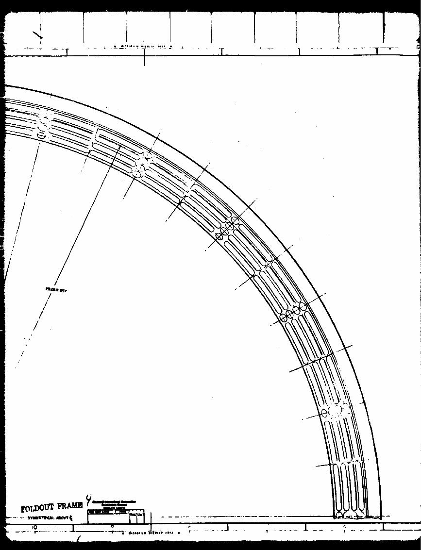
I
/
/
/!
/m
j;
/i
I
/
/
//
/
II.- - I
III
l//

I
.......... i .L_ I
ASIA 75-M
L am m mnm_ &me& i u gIBMnD
*totem
luwYlUU|l) ou _ q_IIM.¢I
lllINm
Yilure 67. L18htwetsht(n_ deo£sn)
Xnne_ Backup Structure
113
h
Im

¢.J!
f_
e-4
!¢,4o_
.e.4
4.d
o
4.d¢t)
o,
¢)t_
tD
"o
4.d
,-4
O
I_RI_CI_ING PAGE t_t,.A,_,'K NOT _'IL_I._
I15

\
I
t_
It_4
4.1U
4.J
4=I
0
II
!U
116
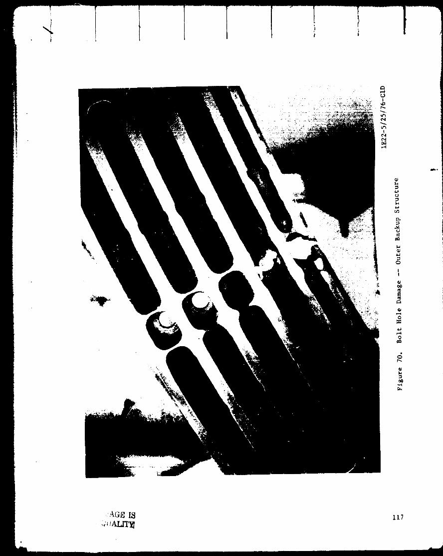
I,.,
m
0
II
q_
1.i
o
i11
=
AGa I_ 117
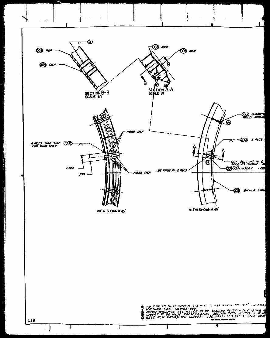
I I I t
,_',',%d_LtVl
8 ,_r,_,ff ?;¢'/,,1',ff/,_'
ViEW SHOWN• 45"
"',F..I II
//.'r.
i
J _:ltC3
cur ._crfo_ 7"o It,MIf._"A3 3mOwN,
viEw SHOWN• 4')"
AIdCKU#
118
A_ _'tf'a_.,l. af yrd,_a _A*'EaJ'AL 4.J..e'& °0 _EO _.F_.a°m't .'ae I_'P ° a_a_ MdCMIME ae_ a_O/OO- _f
I I

, , _!_!_i_ '..
j .Clr£,.q _/8 ,.IULII_C._ OVL V
,.q_iC?"t0._ _ g 0P jau, Al_.,rA3 ,,.q_WN. WIO?'_ 8,,qQNM

which needed replacement. Refurbishment of this structure was partially
completed. The titanium thrust cone and its base were let to a vendor for
remanufacture of the base, and its assembly by E-B welding to the existing
cone. Work was completed on the thrust cone and it was accepted through
inspection at Rocketdyne.
Several of the struts that carry the load from the inner backup ring to
the base of the thrust cone were damaged sufficiently in the fire so as to
require replacement. The tooling required for jigging during assembly by
welding and during the subsequent heat treatment for stress relief was
completed. Additionally, the detail parts, i.e., titanium clevises and
titanium tubing, were completed. This material was ready for assembly by
welding and heat treating when fabrication effort was halted in mid-June.
INTERCONNECT COMPONENTS
The major interconnect components, i.e., fuel and oxygen distribution mani-
folds, are illustrated in Fig. 27. These parts were severely damaged dur-
ing the fire and required substantial replacement. Additionally, a design
modification wa_ made to provide better access than previously existed for
completion of the assembly welds, there being a substantial probability
that it was one of the assembly w_,lds whose failure triggered the test
stand fire incident of 19 November 1975. The redesign of the fuel and
oxidizer interconnecting components was completed and drawings RS005835X
and RSOO5836X, presented here as Fig. 72 and 73, were released to support
fabrication and assembly effort. The usable portions of the previous man-
ifolding were cleaned and refurbished and necessary replacement parts
identified. Fabrication of new parts was never initiated.
il!
119

...._j

...... _ o_.
_ _.JtMk¢ AtF
\
mm
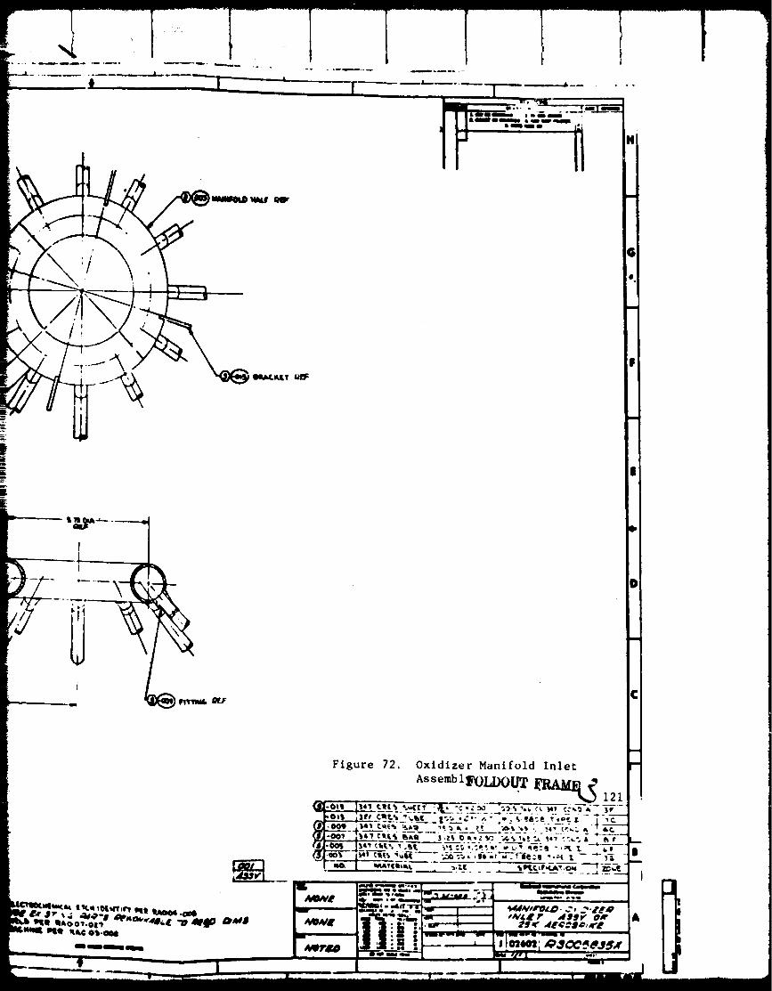
• ° .
PRECEDING PAGE BLANK NOT FI_,I_
I
.m_ _--_ r_,,_"_ _ ,_
v,EwBLFOl
[_)LDOUT FRAME [
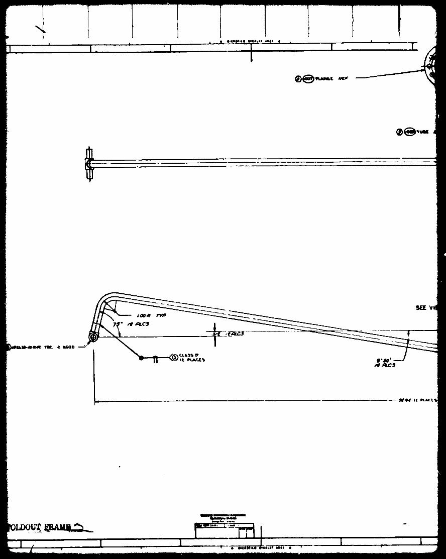
It
| la
!. I|
!
VI
_@4 o! gq.,a,C.t_

& alamm laiitIkiW_ _ Im lip mmml
|
W_Em
pINL_C._(Y
C,,I.A'_ •
_,1Ltm_r,,.tl._
_g t_Q_
ORIGINAE PAGE IS
OF POOR OUAT,TTY iA_Vl
t II, f,.L'_Q_t4,'Nb, lYr.lL _.q'T_t'_ eMt I_O04,.OOI
Figure 73. Fuel Manifold Inl, t
Assembly__LI1
_]-o,,_ l_' c,.t., _.tt_ "ZL._:o.z._______"_.,,.,,,, :. I,_ ::.,_• ::- " .._,' ..'-e.',:_ ,;:. : • -
-,o', 1-3 c-_-s :,,,_; _._ _-_ ;-'_-':._ V_i-:Z _i _'_.._i-
--t...__.c__ [ .... _ .....
_mm_m
_I_NEdl'
/WON_
B.
A

DISCUSSION OF RESULTS
This program set out on a challenglng task--the repair and Kefurblshment
of a seriously damaged thrust chamber assembly, and its hot-firing evalua-tion for both performance and structural integrity. It was recognized atthe start that there were some risks inherent in the objectives, i.e., it
might prove to be impossible to effect the repairs satisfactorily, or
apparently successful repairs might fail prematurely in service. The
risks were Justified by the possible gains. The previous Air Force pro-
gram had successfully demonstrated that an aerospike chamber could bedesigned and fabricated to provide a very substantial reduction in engine
length while attaining a competitive engine weight. The damaged chamber
remaining on termination of the Air Force program presented an opportunityto obtain and hot-fire evaluate an aerospike thrust chamber of flight con-
figuration for very much less than would be required to design, fabricate,and test such a chamber from the beginning.
Several positive results were obtained during the disassembly and repair
procedures:
i. The tubular nozzle repair effort brought out that large-scale
repairs on lightweight tubular nozzles are feasible, returning
the nozzle to a fireable condition at a cost very much less than
that required for complete replacement. The saddle-patch method
developed is applicable in areas where heat fluxes are relatively
modest, and has the advantage of low cost. The tube insert
method is applicable where extensive damage has been done to the
tube, or the heat flux conditions are too high to permit reliance
on saddle-patches.
Both of the tube repair techniques are very dependent for their
success on the skill of the metal fitter and brazer. Before
applying these techniques to an actual nozzle, the technique of
the metal fitter and brazer should be checked by making a number
of sample repairs.
Quality assessment techniques have been developed to permit deter-
mination of the quality of the repaired nozzle areas short of
actually firing the assembly and replacement of defective repairs.
Cryogenic shock testing, air flow checking, pneumostatlc testing,
and hydrostatic pressure checking are recommended in each instance.
2. The aerospike structure repairs indicate that it is feasible to
repair such complex stcuctures as the outer titanium backup ring.
3. The work conducted with combustor dissection and reassembly bears
out the basic validity of the concept of the repair of such com-
plex copper channel cooling structures by the method of excising
the damaged areas and brazing properly configured replacements in
their place.
The basic success of these repair techniques must be considered a positive
factor in future evaluations of the aerospike thrust chamber concept.
[_RI_F_D_O, PAOK BLANK NOT
125
It is ironic that the NARIoF-A material condition, which resulted in con-
Clusion of the program, was present in the material immediately after the
initial fabrication of the combustors, and was in no way caused by either
the fire which terminated the previous Air Force program.or by the repair
efforts conducted under the NASA program. It is now also recognized that
the test stand fire that terminated the Air Force program may have origi-nated with coversheet cracking.
Rocketdyne had recognized during all of its procedures with NARIoy-A that
oxygen contamination of the NARIoy and subsequent embrlttlement by exposure
to high temperature hydrogen represented a threat to the integrity of the
NARIoy-A. The embrittlement that did occur was the result of the failure
of the precautions taken to cope adequately with the conditions of exposure.
As is typical on any program, a sample combustor, No. 504, was first fabri-
cated and extensively test fired as a precursor to the 24 combustors of
the complete assembly. No. 504 performed admirably, suffered no cracking
in service and, on examination of samples during the current investigation,
displayed no evidence of hydrogen embrittlement. However, No. 504 was
assembled entirely by the Materials and Processes laboratory personnel and
it is presently realized that their procedures resulted in much less oxi-
dation than subsequent operations in the manufacturing shop. Tt was further
unfortunate that the constraints of time and money prevented the manufac-
ture and dissection of one or more combustors expressly for the purpose of
the evaluation of the soundness of the manufacturing techniques. That
discipline is frequently given lip service but seldom observed.
It is believed that much more satisfactory results would have been obtained
in the initial fabrication program had the NARIoy-Z composition been uti-
lized instead of NARloy-A. NARIoy-Z contains 0.5% zirconium, which acts
as a getter for oxygen, permitting a higher degree of oxygen exposure dur-
ing fabrication than the NARIoy-A composition.
In assessing the overall results of the program, one must keep in mind that
the material cracking problem with the NARIoy-A combustor material does
not have any special significance for the aerospike thrust chamber concept.
Aerospike thrust chambers are fabricated of the same materials as bell
thrust chambers. The problem was a materials processing problem and not an
aerospike problem.
The program did have several positive results for the aerosplke concept,
even though it was not possible to carry it through to the hot-firing
phase. The aerospike must still be regarded as a contender for length-
limited space propulsion application. The developmental programs pre-
viously conducted have demonstrated the concept's performance and length
advantages. The previous Air Force program demonstrated that an aerospike
thrust chamber roughly 20% of the length of an equivalent bell chamber
could be designed and fabricated to a competitive weight. And the presentNASA contract demonstrated that maintenance and repair procedures will be
available for aerosplke thrust chambers that will permit cost-effective
repairs t- their assemblies.
126