NASA CR 134507 THERMAL, THERMOELASTIC, AND .... WEISS, TECHNICAL MONITOR R.L. JOHNSON__TECHNICAL...
54
NASA CR 134507 A THERMAL, THERMOELASTIC, AND WEAR ANALYSIS OF HIGH-ENERGY DISK BRAKES F.E. KENNEDY, J.J. WU, AND F.F. LING TRIBOLOGY LABORATORY MECHANICS DIVISION RENSSELAER POLYTECHNIC INSTi x I h, If-% A I %I/-% mI/ I "N n I IKUT, INWVV TUKI\ ILJOV"1 f January 1974 Prepared for AEROSPACE SAFETY RESEARCH AND DATA INSTITUTE LEWIS RESEARCH CENTER NATIONAL AERONAUTICS AND SPACE ADMINISTRATION CLEVELAND, OHIO 44135 UNDER NASA GRANT NGR 33-018-152 S. WEISS, TECHNICAL MONITOR R.L. JOHNSON__TECHNICAL ADVISOR Reproduced by NATIONAL TECHNICAL INFORMATION SERVICE US Department of Commerce Springfield, VA. 22151 UNASA-CR-134507) A THERBALo N74-18325' THEBHCELAS!IC, kJD UEA~ AVALYSIS OF HIGH-ENERGY DISK BRAKES (Rensselaer Polytechnic Inst.) -53 p HC $5.75 Unclas CSCL 20K G3/23 31693 https://ntrs.nasa.gov/search.jsp?R=19740010212 2018-06-25T22:51:45+00:00Z
-
Upload
nguyentruc -
Category
Documents
-
view
216 -
download
1
Transcript of NASA CR 134507 THERMAL, THERMOELASTIC, AND .... WEISS, TECHNICAL MONITOR R.L. JOHNSON__TECHNICAL...
NASA CR 134507
A THERMAL, THERMOELASTIC, AND WEAR ANALYSIS OFHIGH-ENERGY DISK BRAKES
F.E. KENNEDY, J.J. WU, AND F.F. LING
TRIBOLOGY LABORATORYMECHANICS DIVISION
RENSSELAER POLYTECHNIC INSTi
x I h, If-% A I %I/-% m I/ I "N n IIKUT, INWVV TUKI\ ILJOV"1 f
January 1974
Prepared for
AEROSPACE SAFETY RESEARCH AND DATA INSTITUTELEWIS RESEARCH CENTER
NATIONAL AERONAUTICS AND SPACE ADMINISTRATIONCLEVELAND, OHIO 44135
UNDER
NASA GRANT NGR 33-018-152
S. WEISS, TECHNICAL MONITOR
R.L. JOHNSON__TECHNICAL ADVISORReproduced by
NATIONAL TECHNICALINFORMATION SERVICE
US Department of CommerceSpringfield, VA. 22151
UNASA-CR-134507) A THERBALo N74-18325'THEBHCELAS!IC, kJD UEA~ AVALYSIS OFHIGH-ENERGY DISK BRAKES (RensselaerPolytechnic Inst.) -53 p HC $5.75 Unclas
CSCL 20K G3/23 31693
https://ntrs.nasa.gov/search.jsp?R=19740010212 2018-06-25T22:51:45+00:00Z

1. Report No. 2. Government Accession No. 3. Recipient's Catalog No.
NASA CR 134507
4. Title and Subtitle 5. Report Date
A Thermal, Thermoelastic, and Wear Analysis of High-Energy January 1974Disk Brakes 6. Performing Organization Code
7. Author(s) 8. Performing Organization Report No.
F.E. Kennedy, J.J. Wu and F.F. Ling
10. Work Unit No.9. Performing Organization Name and Address
Rensselaer Polytechnic Institute 11. Contract or Grant No.Troy, New York 12181
NGR 33-018-152
13. Type of Report and Period Covered
12. Sponsoring Agency Name and Address Contractor Report
National Aeronautics and Space AdministrationWashington, D.C. 20546 14. Sponsoring Agency Code
15. Supplementary Notes
Sponsored by Aerospace Safety Research and Data Institute Lewis Research CenterC, David Miller - Technical MonitorR.L. Johnson - Technical Advisor
16. Abstract
This report describes a thermomechanical investigation of the sliding contact problemencountered in high-energy disk brakes. The analysis includes a modelling, using thefinite element method of the thermoelastic instabilities that cause transient changesin contact area to occur on the friction surface. In order to include the effect ofwear at the contact surface, a wear criterion is proposed that results in the predictionof wear rates for disk brakes that are quite close to experimentally determined wearrates. The thermal analysis shows that the transient temperature distribution in adisk brake assembly can be determined more accurately by use of this thermomechanicalanalysis than by a more conventional analysis that assumes constant contact conditions.It also shows that lower, more desirable, temperatures in disk brakes can be attainedby increasing the volume, the thermal conductivity, and, especially, the heat capacityof the brake components.
17. Key Words (Suggested by Author(s)) 18. Distribution Statement
Surface temperatureSuFriction and wear Unclassified - unlimitedFriction and wearFinite element method
19. Security Classif. (of this report) 20. Security Classif. (of this page) 21. No. of Pages 22. Price*
Unclassified Unclassified i E/Y, '7B
For sale by the National Technical Information Service, Springfield, Virginia 22151
NASA-C-168 (Rev. 6-71)

FOREWORD
This work was conducted as part of NASA Grant NGR 33-018-152 from the
Office of University Affairs, Washington, D. C. 20546. Mr. C. David Miller
of NASA's Aerospace Safety Research and Data Institute was the technical
monitor. Mr. R. L. Johnson, Manager of NASA's Lubrication Research Branch
was the technical advisor. Dr. F. F. Ling, Chairman of RPI's Mechanics
Division was the principal investigator. Acknowledgement is made of the
many helpful suggestions made by C. David Miller and R. L. Johnson of NASA
during the course of this investigation, and of Mr. S. Weiss who is the
new technical monitor.
ii

TABLE OF CONTENTS
Page
Section
1. SUMMARY ............................................................ 1
2. INTRODUCTION .................................................. 2
3. METHOD OF ANALYSIS ........................................ . 4
3.1 The Physical Problem and its Finite ElementIdealization .............. ......................... . .. . 4
3.2 Procedure for Thermal Analysis .......................... 73.3 Procedure for Thermoelastic Analysis .................... 93.4 Contact Area Determination ............................. 113.5 Wear Analysis using the Stress Transfer Method .......... 13
4. RESULTS AND DISCUSSION ....................................... 18
4.1 Analysis of Single-Pad Brake ............................ 184.2 Analysis of Annular Disk Brake .......................... 224.3 Effect of Thermal Parameters on Brake
Temperatures ........................................ 274.4 Effect of Component Thickness on Brake
Temperatures ........................................ .... 34
5. CONCLUSIONS ........................................... 39
APPENDIX A Development of Finite Element Equation forThermal Analysis ..................................... 40
APPENDIX B Flow Chart for Solution of Sliding ContactProblem ......................................... 43
APPENDIX C Nomenclature ....................................... 45
REFERENCES ................................... .......... 49
iii

SECTION 1
SUMMARY
This report describes a thermomechanical investigation of the sliding con-
tact problem encountered in high-energy disk brakes. The analysis includes a
modelling, using the finite element method of the thermoelastic instabilities
that cause transient changes in contact area to occur on the friction surface.
In order to include the effect of wear at the contact surface, a wear criterion
is proposed that results in the prediction of wear rates for disk brakes that
are quite close to experimentally determined wear rates. The thermal analysis
shows that the transient temperature distribution in a disk brake assembly can be
determined more accurately by use of this thermomechanical analysis than by a
more conventional analysis that assumes constant contact conditions. It also
shows that lower, more desirable, temperatures in disk brakes can be attained by
increasing the volume, the thermal conductivity, and, especially, the heat capacity
of the brake components.
SECTION 2
INTRODUCTION
This thermal and thermoelastic investigation will consider the sliding con-
tact problem encountered in high-energy disk brakes of the type used in the
wheels of large aircraft. In such brakes large amounts of thermal energy are
generated at the friction surfaces and this can cause very high temperatures and
large thermal deformation in the brake components, overheating of the wheel com-
ponents, excessive wear of the contacting surfaces, and, possibly, unsatisfactory
braking performance. An accurate knowledge of the temperature distribution and
thermal deformation in these high-energy brakes, especially near the sliding in-
terfaces, is necessary in order to insure that the brakes will perform reliably
under the severe conditions encountered in service.
The thermal analysis of bodies in sliding contact has attracted the interest
of many investigators because of its importance in many situations in which fric-
tion occurs. Most work has been concerned with relatively light loading situa-
tions, for which experiments have shown that contact occurs mainly at and near
surface asperities, with localized high "flash temperatures" occurring at the
small contact spots. Most analyses of this type of temperature distribution have
assumed that the contact spots are widely-separated and do not interact, thus en-
abling application of a solution for the case of a single isolated contact based
on the work of Blok (Ref.l) and/or Jaeger (Ref.2). A different approach for this
situation has been to assume a stochastic model for heat generation which con-
siders the distribution of the spots of actual contact on the friction surface
to be random in both space and time (Ref.3,4).
Although these investigations have given much useful information about tem-
peratures occurring in low-energy sliding systems, they cannot completely describe
the situation in brakes, where the loading is relatively severe. Several experi-
mental investigations (Ref.5,6,7) have shown that when large loads are applied to
sliding bodies the contact areas are not small and widely-separated like asperi-
ties, but are discrete areas that are intermediate between asperity size and the
dimensions of the apparent contact area.
2.
Barber (Ref.6) has shown graphically that the formation and movement of
these areas of actual contact are determined by the thermomechanical processes
of thermal deformation and wear. A non-uniform pressure distribution on the
contact surface causes non-uniform heat generation' with higher temperatures
resulting at areas of greatest contact. Greater thermal expansion at the hot
contact areas causes contact to become more concentrated at those areas until
wear is great enough to force the contact to shift elsewhere.. Thus, "thermo-
elastic instability" occurs on the contact surface. Although Barber assumed
that the initial non-uniformity arose because of surface irregularities, other
analyses (Ref.8,9) have shown that even for smooth surfaces the heat generated
at the sliding interface can cause changes in pressure distribution and contact
area.
It is apparent from the above discussion that an accurate analysis of
transient temperatures in high-energy sliding systems must account for thermal
deformation, and vice versa. Previous brake analyses have neglected this inter-
dependence, and have assumed that either the entire contact area (Ref.10) or
widely-separated spots (Ref.ll,12) remained in contact throughout the braking
period. In our work a thermomechanical analysis will be performed, using the
finite element method, in which the contact areas and the pressure distribution
within them will be determined by a thermoelastic analysis and will then be used
in a thermal analysis to find the transient temperature distribution in the disk
brake. A wear model will be proposed that will allow both the modeling of the
thermoelastic instabilities observed by Barber and the estimation of the amount
of wear that occurs on the contact surface. The effect of different material
parameters on the temperature distribution will be investigated in an attempt
to determine the parameters most important for safe and reliable brake performance.
No analysis of this type has yet been reported and it is felt that it would be
difficult, if not impossible, to carry out the analysis using classical techniques.
3.

SECTION 3
METHOD OF ANALYSIS
3.1 The Physical Problem and its Finite Element Idealization
A typical aircraft disk brake assembly is shown in Figure la. The brake con-
sists of a number of stationary and rotating disks, with the rotating disks being
splined to the aircraft wheel. When the brake is applied, a hydraulic piston
exerts pressure on the end disks and this pressure is transmitted through the
stack, causing friction between the stator and rotor disks and transforming large
amounts of kinetic energy to thermal energy.
In our analysis of the temperature distribution and thermal deformation in
the disk brake we will examine a typical section shown in Figure lb. The section
is bounded by plane A-A, the midplane of a stator disk,and plane B-B, the midplane
of a rotor disk, and contains one friction surface. We will assume that the mid-
planes of the stator and rotor disks are planes of symmetry for both deformation
and temperature fields. It will also be assumed that the total force acting on
planes A-A and B-B is the same as that applied to the end disks by the hydraulic
piston, thus neglecting friction at the splines. The rotating disk usually con-
sists of a segmented lining, often of hardened alloy steel, attached to a thin
annular disk. A typical stator disk consists of a number of pads containing fric-
tion material rigidly attached to both sides of an annular backplate. In our work
we will assume that variations in temperature, stress, and displacement in the cir-
cumferential direction can be neglected in both stator and rotor, thus enabling an
axisymmetric analysis.
The finite element idealization to be used in this analysis is shown in
Figure 2a. The geometry of the model has been chosen to conform as closely as
possible to that of an actual aircraft wheel brake. Except for those calculations
in which the effect of different material parameters is being studied, all material
properties used in the investigation will be the properties of the actual brake
materials. Letters A through E are assigned to points inside the brake that are
referred to in later sections of this report.
The finite elements used in the analysis will be axisymmetric ring elements
of triangular cross-section. At the friction surface, however, a slight variation
will be made. It is quite important that effects of directional stiffness in those
4.

0 0
r B
RO
TO
R
DIS
C
FR
ICT
ION
P
AD
F
RIC
TIO
N
SF
RIC
TIO
N
STA
TOR
D
ISC
M
IDP
LA
NE
O
F S
TATO
RD
ISC
U,

Figure 2a. Finite Element Idealization of Brake Section
2 4 2 4 2
Figure 2b. A Typical Source Element. Element nodes identified by numbers 1-4.

elements be eliminated as much as possible since it is those elements in which
contact occurs, heat is generated, and wear is possible. In order to accomplish
this a new composite element has been developed for the friction surface by super-
position of four triangular ring elements. In this superposition, which is shown
in Figure 2b, each set of two triangular elements consists of one surface element
from the stator disk and one from the rotor, with each element having one-half of
its normal stiffness. The result is a quadrilateral composite element which is
composed of both stator and rotor materials. We will call these elements "source
elements" and will discuss in later sections their part in heat generation, wear
analysis, and contact area determination.
The procedures to be developed here for analysis of an annular disk brake will
also be applied to a similar analysis of a caliper disk brake, so that the ana-
lytical results can be compared with experimental data obtained recently (Ref.7)
for that type of brake. The caliper brake, which is similar to the disk brakes
used in automobiles, is not actually axisymmetric, but will be approximated as such
for the purposes of this analysis.
A difference in the finite element idealization for the single pad problem
is that the elements in the stationary disk (the pad) are no longer rings, but are
now ring sectors. The composite source elements for this configuration are made
up of two rotor elements of volume 2nrA and two pad elements of volume BrA,
where A is the cross-sectional area of the triangular elements, is the centroidal
radius of the element, and B is the included angle of the ring sector.
In all our work we will assume that coupling between the thermal and thermo-
elastic equations can be neglected, so that the two equations may be analyzed
separately.
3.2 Procedure for Thermal Analysis
Our analysis of the temperature distribution in the brake will be carried out
using the finite element method, which has been applied to the investigation of
heat conduction problems by a number of analysts in the past seven or eight years.
It can be shown (see Appendix A) that the set of nodal temperatures (Tij in
a body obeying Fourier's law of heat conduction may be found for a given set of
7.
boundary conditions by solving a matrix equation of the form:
[TS][Ti] = [FT (1)
where [TS] is a "thermal stiffness matrix" dependent on the thermal properties of
the body and [FT} is the matrix of "thermal loads" applied to the body, consisting
of heat generation, prescribed heat flux, and convection at the boundary. Equa-
tion (1) is the basic finite element equation to be used in our thermal analysis.
The formation of the matrices to be used in Eq.(l) and the solution of that matrix
equation is, for the most part, straightforward. The boundary conditions and the
heat generation at the friction surface require further explanation, however.
For our work we will assume that the mechanical work done by friction is
entirely transformed into heat energy and that this heat is generated inside the
source elements on both sides of the friction surface. This is in line with the
conclusion by Ling and Pu (Ref.3) that the heat is generated slightly below the
friction surface by means of material deformation.
Before each incremental thermal analysis a thermoelastic analysis must be
performed (see following sections) and from that analysis we will know which source
elements are in contact at the beginning of the increment and the stresses in those
contacting elements. Since the friction surface lies in the center of the source
elements, the pressure Pe acting on the friction surface will be the oz acting at
the centroid of the source element. It will be assumed that this pressure and the
contact area remain constant throughout the time increment and that short time
increments will be specified so that this assumption will be reasonably valid.
If the angular deceleration w of the wheel remains constant during the braking
cycle, the heat generation rate in the source element during a time increment of
length At will be:
P frA
SJA - R (2)
whereA = contacting area of stator element =-- (r - r.)p 2 o -
f = coefficient of friction
.,ro ,r = centroidal,, outside, and inside radii of element
= initial angular velocity of wheel
8.

t = time at end of increment
J = conversion constant between mechanical work and heat energy.
The source elements are made up of four triangular elements of thickness he)
with two of the elements being in the stator (friction pads) with contacting2 2
area Ap, and two in the rotating disk with contacting area A = (r2 - ri). If
the heat generation rate/unit volume in each of the triangular elements is 4, then
P ffA= e p- 1 (3)
q Jh (A +A 2 ]e p D
for source elements that are in contact. For all other elements q = 0. (Note:
for annular brake A = AD
A partitioning of the generated heat between pad and disk elements is not
necessary in our finite element analysis, since the heat, once generated, may
easily be conducted across the friction surface. The thermal resistance due to the
formation of oxide films on the friction surface (Ref.22) will be neglected here.
In our investigation, since all heat input is taken care of by the above-40
generation terms, there will be no non-zero prescribed heat flux q , on any sur-
face. Since midplanes A-A and B-B (see Fig.lb) are planes of symmetry for the
temperature field, there will be no heat flux across those planes. Although no
heat flux will be prescribed on the inner and outer boundaries of the section,
heat transfer by convection at those surfaces could be allowed in cases where
brake cooling is being considered.
3.3 Procedure for Thermoelastic Stress Analysis
The loading on our brake section consists of both axisymmetric and antisym-
metric loads. Both the pressure applied at the midplanes of the disks and the
temperature field are axisymmetric and the stresses and deformation caused by them
will be found using the axisymmetric finite element equations for uncoupled
thermoelasticity.
The additional loading caused by friction at the contact surface is antisym-
metric, and the stresses resulting from this loading will be added to the axisym-
metric stresses by superposition. In the source elements, which are the only
9.
elements for which a stress distribution is required, the sole antisymmetric
contribution to the stress field is:
Tz = fPe (4)
where P eis the axisymmetric stress component oz acting at the center of the source
element.
The finite element equation that will be employed in the axisymmetric stress
analysis is of the well-known form
[ST](DISI = (FNI = [FT) + (FF} + [FS) + (PI (5)
where [ST] is the system stiffness matrix, [DIS) is the matrix of nodal displace-
ments, and [FNJ is the matrix of nodal loads, with the latter being made up of
contributions from thermal stresses, body forces, surface tractions, and concen-
trated external forces. The details of the derivation of (5) may be found else-
where (Ref.14,15), but briefly the derivation proceeds as follows: A potential
energy functional 1e is determined that is valid in each element of the elastic
body. An appropriate function, in our case linear, is used to relate the value
of the independent displacements at a point inside an element to their values at
the element nodes, and this function is used, along with the stress-strain and
strain-displacement relations of linear elasticity, to get the potential energy
functional rre in terms of nodal displacements. The first variation of the ele-
mental potential energy functional, 6ne, is then found with respect to admissible
variations in nodal displacements and, after summing the 86e for all elements,
the principle of minimum potential energy, ZES e = 0, is applied to get the re-
sulting equation (5). It might be noted that (5) is similar in form to Eq.(l),
the finite element equation for use in the thermal analysis, thus enabling use
of the same computer subroutines for the solution of both equations.
For the axisymmetric analysis we will use the following boundary conditions
on the external boundary: (referring to Fig.lb)
on midplane B-B w = 0 (fixed for reference purposes)
T =0rz
on midplane A-A w = 8 (constant with respect to r)
T =0.rz
10.
With these boundary conditions the midplanes remain plane and symmetry is
preserved. We will also assume that all surface tractions on the inside and out-
side boundaries are zero, and that bending stresses may be neglected.
The value of 8 will be such that at all times the total applied load is
F ppl the force applied by the hydraulic piston. We will assume that this appliedappl'force, but not necessarily the pressure distribution caused by it, remains constant
throughout the braking cycle. In order to determine the 8 that will produce a
total applied force of F- during an increment we proceed as follows:appl
For each time increment we will assume a displacement w = 6 on midplane A-A,
solve matrix equation (5) for the displacements (DISI, and use these displacements
to find the stresses present in each element. The elastic stresses will then be
integrated numerically along a plane parallel to A-A and the resultant Ftot in the
direction perpendicular to A-A will be compared with the given applied load Fappl
If Ftot / Fappl a correction will be made to 6 such that the equality will exist
after the displacements and stresses are recomputed.
After we have found a solution for the incremental stress distribution for
which Ftot = Fapply we may proceed to determine whether any changes in contact
area have occurred in the increment.
3.4 Contact Area Determination
Transient changes in actual contact area occur on both the microscopic (surface
asperity) and macroscopic scale during sliding contact between deformable bodies.
In our work we will examine only the macroscopic changes and will assume that within
areas of gross contact the number of asperity contacts is large enough that perfect
contact is attained. Similarly, within the areas of non-contact it will be assumed
that the number of asperity contacts is so small that no effective contact occurs.
In our contact area determination we will examine each source element indi-
vidually, after having calculated the thermoelastic stress distribution using the
methods of the previous section. Changes in contact area will therefore occur by
means of the addition or subtraction of the bands of contact swept out by single
source elements. For our finite element mesh, the single element bands will each
comprise less than 5% of the total possible contact area. The contact/non-contact
determination for the individual elements will proceed as follows:
11.

For elements presently in contact:
The criterion for contact is Pe <0 (compression), wherePe is the value of az
at the center of the source element. If the criterion is met, the element re-
mains in contact through the next iteration. If, however, Pe > 0, a tensile
stress is present at the contact surface and that is impossible. In order to
remove the element from contact and to make the resulting adjustments in the
stress field, we will use the stress transfer method, which was: originally de-
veloped for a "no-tension" rock mechanics application (Ref.16).
The non-contacting source elements will, in effect, contain a fissure and
will be unable to sustain any normal and shear stresses on the contact surface.
Those elements become, therefore, transversely isotropicY with the stress-strain
constitutive relationship being given by
' 1 - v v 0 0r r
S= E - v 0 0 = [D'])e (6)(1+v)(1 - 2 v)
0 0 0 0 0 ez0 0 0 0 0 e
For the same elastic strain [e), however, our finite element analysis, which as-
sumes isotropic material behavior, predicts an elastic stress
a I -v v v 0 r
E[e } = (,= v 1-v v = [D]E) (7)
e (1 + v)(1 - 2v)
Sv v 1 - v 0 e0 0 0 1 - 2v z
7 2 eTrz - rz
The excess stress [Ac'} = (Oe) - [') must be transferred from the source element
to surrounding elements and this is done by equilibrating ([Ac" by a set of
forces (P"' acting on the element nodes and then removing the set of forces to
allow the body to deform further. Although in most stress transfer applications
the system stiffness matrix [ST] is left unchanged and a number of stress transfer
iterations are done until [ae) = ([a', it has been found advantageous in this
analysis to recompute [ST] using the constitutive relation given in (6) for all
non-contacting source elements. This enables a large reduction in the number of
stress transfer iterations required.
12.

In addition to the inability of the non-contacting source elements to transmit
loads across the fissured contact surface, they also are unable to conduct heat
across the interface. This is accomplished in our analysis by setting kz = 0 in
the thin source elements which are no longer in contact. This necessitates a
change in the thermal stiffness matrix [TS] at the same time that [ST] is recom-
puted. Because of these stiffness matrix changes, the non-contact elements will
have a r= = Tze = 0, k = 0, and 4 = 0 until the stiffness matrices are changed
again when the elements come back into contact.
For source elements presently not in contact:
In addition to examining the contacting elements to see if contact has been
lost, we must also examine non-contacting source elements to see if contact has
resumed at those elements. The stress in the elements not in contact will be
given by (6), while the axisymmetric stress that would be present if the element
were in contact is given by (7). If o at the center of the element is compres-ze
sive (Pe < 0) then the element has resumed contact and the stress transfer process
must be used again, this time to transfer stress back to the element. In this case
the stress to be transferred is oT a" = (0' - { el.
We will also have to change [ST] and [TS] again, this time returning the ele-
ment's contributions to their original values. After these changes have been ac-
complished and the stress has been transferred, the element can be treated like
any other contacting source element.
3.5 Wear Analysis using the Stress Transfer Method
Although wear is one of the most common modes of material behavior, it is very
difficult to express accurately a quantitative law for wear prediction because of
the many factors that affect wear. A large amount of research in this area has
been carried out in the past 20 years in an attempt to get a better understanding
of the wear process and, although it has not resulted in a wear law that can be
used in our work, a number of observations have been made which help us in our
approximation of such a law (Ref.17,18,19). It is assumed that the following con-
clusions drawn from metallic wear research (Refs.17,18.19), will also hold true for
all materials under investigation here.
13.
- Wear rates are, in general, directly proportional to load, and inversely
proportional to the hardness or yield stress of the material being worn.
- When two materials of different hardness are in sliding contact, wear is
usually more severe in the softer material.
- Wear usually increases with increasing temperature. Although this is due to
many factors, mainly metallurgical, it has been shown by Lancaster (Ref.20)
that, at least for some materials under certain conditions. most of the in-
crease of wear with temperature is accounted for by a decrease in hardness
with increasing temperature.
- Wear is dependent more upon distortion or shear stresses than upon dilata-
tional stresses. Analytical models for low wear have been developed which
use the maximum shear stress as a measure of loading (Ref.21).
Based on these observations and upon the requirement that, for our incre-
mental finite element analysis, wear should take place in discrete steps instead
of by the actual continuous process, the following wear criterion was chosen for
use here:
If the energy of distortion for a source element, given by the second invari-
ant, J2, of the stress deviator tensor, equals or exceeds a critical value, W,based on the temperature-dependent yield stress of the element material, wear will
occur. If J2 < W no wear will occur in the element. For our analysis
12 L r F - )2 + (q -z)2 + (a r)2 + 62r z + 6T 2 (8)eL r z z r rz ze
and 2
W = y3
where ay = y (T) for the softer of the two materials in the composite source
element.
In order to prevent our wear criterion from being satisfied when the source
element is not in contact, we will also require that the magnitude of Tz9 acting
at the friction surface have a finite value, or ITzel > 0.
Upon examination of the above, it can be seen that our wear criterion is
actually a modified criterion for plastic flow. Although the occurrence of wear
in most materials is preceded by some localized plastic deformation, we will be
neglecting the plastic deformation in our work. We will instead assume that,
14.
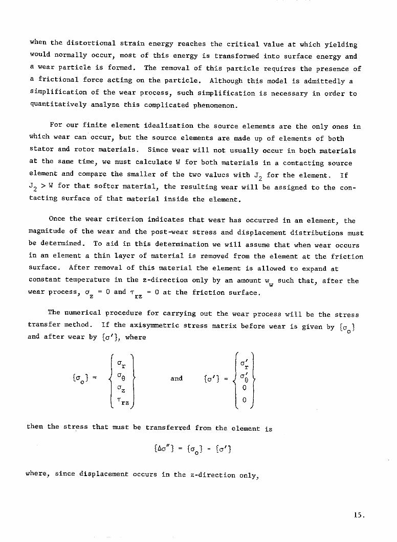
when the distortional strain energy reaches the critical value at which yielding
would normally occur, most of this energy is transformed into surface energy and
a wear particle is formed. The removal of this particle requires the presence of
a frictional force acting on the particle. Although this model is admittedly a
simplification of the wear process, such simplification is necessary in order to
quantitatively analyze this complicated phenomenon.
For our finite element idealization the source elements are the only ones in
which wear can occur, but the source elements are made up of elements of both
stator and rotor materials. Since wear will not usually occur in both materials
at the same time, we must calculate W for both materials in a contacting source
element and compare the smaller of the two values with J2 for the element. If
J2 > W for that softer material, the resulting wear will be assigned to the con-
tacting surface of that material inside the element.
Once the wear criterion indicates that wear has occurred in an element, the
magnitude of the wear and the post-wear stress and displacement distributions must
be determined. To aid in this determination we will assume that when wear occurs
in an element a thin layer of material is removed from the element at the friction
surface. After removal of this material the element is allowed to expand at
constant temperature in the z-direction only by an amount w such that, after the
wear process, a = 0 and T = 0 at the friction surface.z rz
The numerical procedure for carrying out the wear process will be the stress
transfer method. If the axisymmetric stress matrix before wear is given by Ko}0and after wear by t(o'} where
Or or
ol= 0e and to'} = 'a z 0
rz 0
then the stress that must be transferred from the element is
[a"'I= [ O- ' -(
where, since displacement occurs in the z-direction only,
15.

r r i-V z"
Upon carrying out the transfer of stress it will again be found advantageous
to change the stiffness matrix of the element to that based on Eq.(6) and achieve
rapid convergence using the new stiffness matrix.
If the elastic strain of the element after conclusion of the transfer process
is given by [ej, then the total amount of stress relieved in the element by the
wear process is
o)} = ([D] - [D'])[e3 (9)
where [D'J is given by Eq.(6).
Since we have restricted displacement to the z-direction during the isothermal
wear process, the strain occurring during wear is,
0
0(e w = (10)
ww
We have chosen the displacements to be linear functions of the coordinates, so
_w w
e
where he is the element thickness (z-direction).
A relationship may now be found for the worn thickness w by using (10), (11),
(7) and (9):w
D13 r + D238 + D33 z - azz = D33 he
ora h
zz ew = (12)w D33
16.

Knowing ozzY which is the z-component of the stress that would be present inthe element if no wear had occurred, we can calculate the amount of wear that took
place in the element. It should be noted that if wear has previously occurred in
the element it must be taken into account when calculating ozz so that we will
have
a = D1 3 e + D23 e + D33 - Ezz 13 r 23 D33 z w
where the summation is taken over all previous wear occurrences in the element.
If a resumption or loss of contact occurs in a worn source element, it will
be handled by the procedures developed in Section 3.3. The stress required for
resumption of contact will be different from that given in Eq.(7), however, since
for a worn element (9) becomes
ea e = [D](e} - E (a (9a)
where the E is taken over all wear occurrences in the element.
It might be noted that because of the assumption of axisymmetry, wear in this
analysis takes place in finite steps or delaminations during which an annular
layer of material is removed. Although such annular strips are not normally found
in wear debris, they can be considered to be made up of the many short flat wear
particles that are usually observed.
A block diagram and flow chart showing the computational process used in the
solution of this problem is included in Appendix B.
17.

SECTION 4
RESULTS AND DISCUSSION
4.1 Analysis of Single-Pad Brake
The analytical procedures outlined in the past section will first be applied
to a thermomechanical investigation of a caliper-type disk brake-having one fric-
tion pad on each face of a rotating disk. Such a brake has recently been studied
experimentally at the RPI Tribology Laboratory by Santini (Ref.7).
The finite element idealization will be similar to that shown in Figure 2
with the stator elements being ring sectors. The friction materials will be those
used in the Boeing 747 aircraft brake, with the rotating disk being of high strength
alloy steel and the friction pad composed of a sintered copper-based composite
enclosed in a carbon steel cup. The stator backplate will be aluminum, and in
order to account for the thermal contact resistance between it and the friction
pad, several elements at that interface will be assigned zero conductivity per-
pendicular to the interface. Although some cooling of the rotating disk takes
place in practice, it will be neglected here and all external surfaces will be
assumed to be insulated.
We will assume that the friction pad and rotating disk both are initially rela-
tively smooth and that, upon initial application of the brake, perfect contact oc-
curs across the entire pad surface. Because of a difference in sliding velocity
between inside and outside radii, however. the heat generation rate varies across
the pad. This causes a nearly immediate concentration of the contact area to a
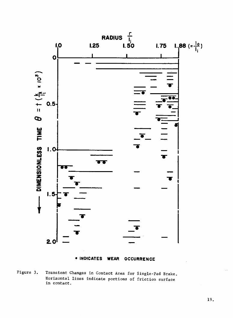
region near the outside of the friction pad. This contact area change is illus-
trated in Figure 3 in which the complete initial contact is shown at the top
(0 = 0). Soon the contact becomes more and more concentrated in one small band
near the outside of the pad. The stress level in the small contact area gets quite
high and shortly (at 0 - .25) wear occurs at the concentrated contact and several
other source elements come into contact. Once again a concentration of contact
occurs, followed by wear and a shift of contact to another area, and this cycle re-
peats itself a great many times during brake application. Thermoelastic instabili-
ties of the type experimentally observed by Barber (Ref.6) are therefore predicted
by this disk brake analysis.
18.
rRADIUS I
I 0 1.25 1. 50 1. 75 . 88 (= )0I
o --
- - -,-
IO
-:*
1. 5- - - ,z
I
u-r
19.
- -_
19.

At any one time the temperature distribution on the friction surface is very
pon-uniform, with temperatures being quite high in contact zones or zones that have
just worn, and lower elsewhere. If uniform contact pressure had been maintained
during braking, with no changes in contact area occurring, a non-uniform tempera-
ture distribution would still be predicted because of the non-uniform velocity
distribution, but the degree of non-uniformity is much greater with the variable
contact analysis.
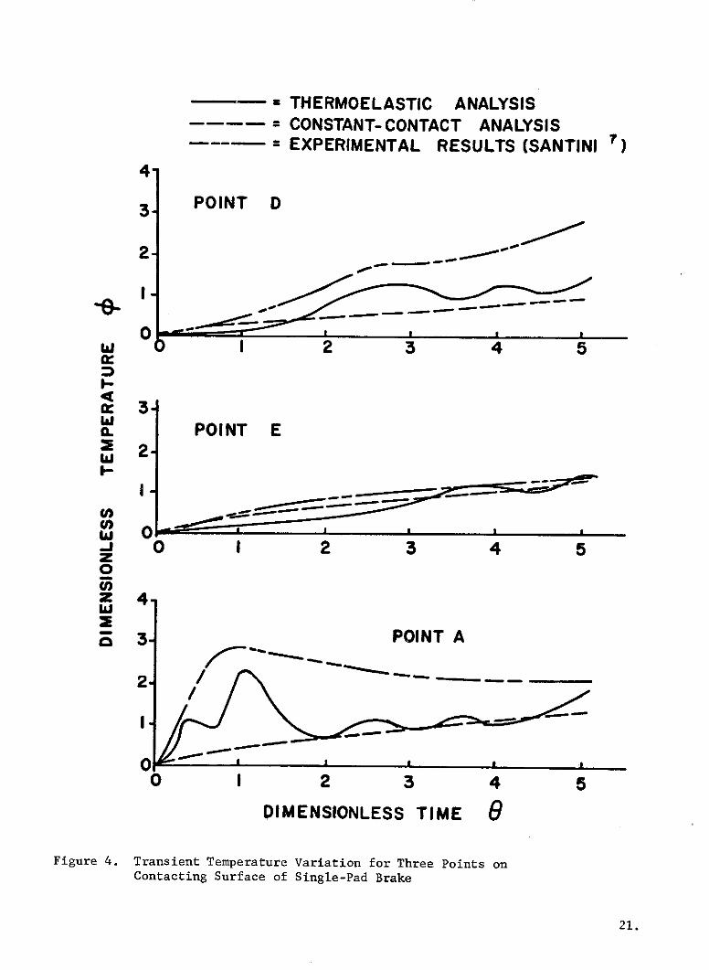
Because of the changes in contact area, the temperature at each point on thefriction surface fluctuates with time. In Figure 4 one can see the transient tem-perature curves for three points inside the friction pad near the contact surface.For each point the temperature determined by this analysis is compared with thatfound by experiment (Ref.7), and with that found by a constant-contact analysis.The latter analysis neglects the effect of thermoelastic deformation and was car-ried out using the same computer program, but setting u = 0 for all materials.The three points investigated are points A, D, and E. as defined in Figure 2.The dimensionless temperature cp used for all curves is defined as
Tk 1= . x 10
Qo
wherekI = thermal conductivity of conventional friction pad material
7 = average radius of friction pad
Qo = initial rate of heat generation.
The upper set of curves in Figure 4 shows the temperature at point D. locatednear the inside radius of the pad surface, while the middle set of curves showsthe temperature at point E near the center of the pad surface. The gradual tem-perature rise at point E throughout the period under investigation and at point Dduring early portions of the time period indicate that concentrated contact wasnot occurring near those points. Later, at about e = 1.5, both the experimentaldata and the thermoelastic analysis show a rise in temperature as contact startsoccurring near point D (see also Fig.3). Although the thermoelastic analysispredicts greater fluctuation in transient temperature than does the experimentaldata, it is perhaps due to the fact that the experimental data is the average ofa number of test runs, with fluctuations being averaged out.
20.
= THERMOELASTIC ANALYSIS= CONSTANT- CONTACT ANALYSIS
----- = EXPERIMENTAL RESULTS (SANTINI )
4-
3 POINT D
2-
O • I I I - -
0- - - -.-
w 0 1 2 3 4 5
.w
2 POINT E- 2
w 00 I 2 3 4 5z
Z 4.
3-0 POINT A
2. i
0 I 2 3 4 5
DIMENSIONLESS TIME G
Figure 4. Transient Temperature Variation for Three Points onContacting Surface of Single-Pad Brake
21.
In reviewing all three sets of curves of Figure 4, it might be concluded
that, although the thermoelastic analysis does not predict perfectly the magni-
tudes of the temperatures at points near the friction surface, it does give a
better prediction than does the constant-pressure analysis used by investigators
in the past. It is able to predict, with some degree of accuracy, the fluctua-
tions in temperature caused by shifting of the contact areas.
It was mentioned earlier that the reason for the concentration of contact is
thermal deformation of the contacting surfaces. Figure 5 shows this thermal de-
formation at e = 0.75 as determined by the thermoelastic analysis. The upper
curve is for the top side of the strip of source elements at the contact surface
while the lower curve is for the disk side of the elements. It can be seen that
the greatest compressive deformation occurs near the elements that are in contact
(see Fig.3).
Since we have calculated and noted the amount of wear that occurred in each
worn element, we are able to determine a predicted wear rate for the single pad
disk brake from our thermoelastic analysis. The wear rate determined in this-8 3
manner is .782 X 10-8 m of pad material/second, averaged out over the duration
of the brake run, with the wear of disk material being negligible. Using the
density of the pad material (4900 kg/m 3) and the initial pad mass (0.157 kg) we
come up with an average ratio of mass of worn material/mass of original pad "A0
equal to .000244 kg/kg/second of run time. The experimentally determined valueM
(Ref.7) is -= .00019 kg/kg/sec of run time. Although our predicted value is
about 28% higher than the actual value, it is felt that this difference is not at
all bad considering the approximations used in determining the wear criterion,
the discretization of the wear process, and the neglecting of plastic deformation
prior to wear. Since the predicted wear rate is of the same order of magnitude
as the actual, the assumed wear criterion must be quite reasonable.
4.2 Analysis of Annular Disk Brake
Having shown in the single-pad brake analysis that our method is reasonably
valid, we will now turn our attention to a similar analysis of an aircraft disk
brake having an annular stator. We will again use a finite element mesh similar
to that shown in Figure 2 with the stator and rotor elements now both being
22.

whe
.0OI DEFORMED
.005
PAD SIDE OF SOURCE ELEMENTS INITIAL
whe
.01
.005.00 DEFORMED
0 DISK SIDE ITIAL
1.0 1.25 1.5 1.75 1.88
RADIUS rli
Figure 5. Thermal Deformation of Contacting Surfaces for Single-Pad Brake at 9 = 0.75.Top curves show initial and deformed configurations of stator pad side offriction surface source elements. Bottom curves show initial and deformedconfigurations of rotor disk side of elements.

complete rings. The geometry of the finite element idealization will be approxi-
mately that of a section of a brake from the Boeing 747 aircraft and the analysis
will attempt to study the condition of rejected takeoff for that aircraft. In
that condition the aircraft is braked from near-takeoff velocity to a complete
stop in a very short time.
The material properties used will be those of the Boeing 747 brake materials.
The only change in material from those used in the single-pad analysis will be
the use of carbon steel for the stator backplate instead of aluminum. We will
again have several elements of zero z-direction thermal conductivity at the inter-
face where the friction pads are attached to the stator disk in order to account
for thermal contact resistance there. All external surfaces are again assumed to
be insulated for purposes of the analysis.
As with the single-pad analysis, the contact between friction pad and disk
is assumed to be initially perfect, but immediately upon contact a non-uniform
velocity distribution causes a larger heat generation rate near the outside radius
of contact. This causes an immediate shift in contact toward the outside as can
be seen in Figure 6. Because of the very high braking energies encountered in the
rejected takeoff condition, temperatures increase rapidly inside the contact zone
and wear begins to occur before the contact has had a chance to become concentrated.
As Figure 6 shows, wear and shifting contact cause the contact zone to move away
from the outside portion of the contact area much earlier than was observed in the
single-pad analysis. Much more wear occurs in a shorter time than was seen in the
single-pad study (Fig.3) and this causes more frequent shifts of contact area. It
should be noted that, because of differences in brake radii, the dimensionless
time grouping ea used in Figure 6 differs from the e grouping used in Figure 3,with 8a = 1.0 corresponding to 6 = 0.338.
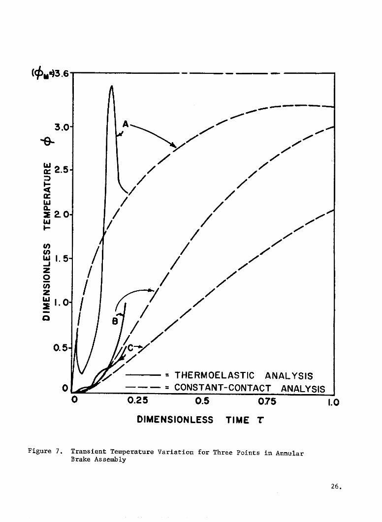
The transient temperatures for various points inside the brake section are
shown in Figure 7. Curves A are for point A, lying near the friction
surface of the stator pad (see Fig.2). Point B lies on the center plane of the
rotating disk at the same radius as point A and point C lies inside the friction
pad at a point where the friction material meets the steel cup that encloses it.
The solid curves of Figure 7 are for a variable contact analysis, while the dotted
curves are for a constant contact analysis which.neglects thermoelastic deformation.
No published experimental data is available for comparison for the case of an
annular brake. The dimensionless time T for these curves equals t/tf, where tf is
the elapsed braking time when the aircraft comes to a stop.
24.

RADIUS _-1.0 1.25 I.48= )
- * OIII-
C 0 .2 5- 0_0
0 .5 - - --Co* -
0 -
Z -
0.75- " - -
1.0 - W-
* INDICATES WEAR OCCURRENCE
Figure 6. Transient Changes in Contact Area for Annular Disk Brake.Horizontal lines indicate portion of friction surface ininstantaneous contact.
25.
AA3.0 A
i-
/"A
/ AI blS1.5- /
0.5 /
i THERMOELASTIC ANALYSIS0 = CONSTANT-CONTACT ANALYSIS
0 0.25 0.5 075 1.0
DIMENSIONLESS TIME '
Figure 7. Transient Temperature Variation for Three Points in AnnularBrake Assembly
26.

It can easily be seen that the contact surface temperatures are higher than
those inside either the pad or the disk. The temperatures calculated by the
variable-contact analysis tend to be higher than those calculated by the constant-
contact analysis, with relatively severe temperature fluctuations predicted near
the contact surface by the thermoelastic analysis. The fluctuations are damped
out considerably at points inside the brake components. The wide fluctuations
near the contact surface are due to the very large heat energies that are gener-
ated in the concentrated contacts for this problem, but the ability of the con-
tacting bodies to absorb and dissipate heat helps keep the temperatures inside the
bodies from varying as rapidly. The temperatures have been found to be dependent
on the material properties and geometry of the contacting components and these
effects are examined more closely in the next sections.
The magnitudes of the temperatures attained in this problem are quite a bit
larger than those found with the single-pad analysis because of the higher contact
pressures in this rejected takeoff analysis. The melting temperature of the fric-
tion material is approximately pm = 3.6 and is shown on Figure 7. It can be seen
that the temperatures at the concentrated contacts on the friction surface approach
this temperature quite early in the braking cycle. This causes a problem with the
thermoelastic analysis because of the very high wear rates at such high tempera-
tures. We are faced with the choice of either making the time increments very
small in order to decrease the amount of wear during each increment, or making a
very large number of stress transfer iterations to complete the wear process if
larger time increments are used. Either case requires a great deal of computer
time and, because of this, the thermoelastic analysis had to be stopped early in
the braking cycle.
It should be mentioned that when rejected takeoff conditions are encountered
in practice the brakes face much the same conditions mentioned above, with very
large amounts of wear and some melting occurring. Brakes that encounter such aservice condition are replaced immediately, since they are no longer useable.
4.3 Effect of Thermal Parameters on Brake Temperatures
This part of the investigation is concerned with determining the effect of thedifferent thermal properties of the disk brake materials on the temperature distri-bution in the brakes. In order to isolate the effect of the thermal parameters
27.

under investigation, the effects of thermal deformation and wear were eliminated
by setting the coefficient of thermal expansion (a) equal to zero for all materials
in the brake, thus keeping the contact area constant. The configuration used in
these tests was that shown in Figure 2, using a full-circle stator (annular fric-
tion pad).
It was desired to investigate the relative importance of the following thermal
properties:
thermal conductivity of the disk (rotor) material) kdisk
thermal conductivity of the friction pad material kpad
specific heat of the disk material cdisk
specific heat of the friction pad material cad
A series of five curves were obtained; one in which the properties of the conven-
tional Boeing 747 brake materials were used, and four others, each having one
thermal property differing from its original value. The changed values used in
these four tests were not meant to correspond to those of any actual material,but were set at twice their normal values. The geometry was kept constant for all
five tests.
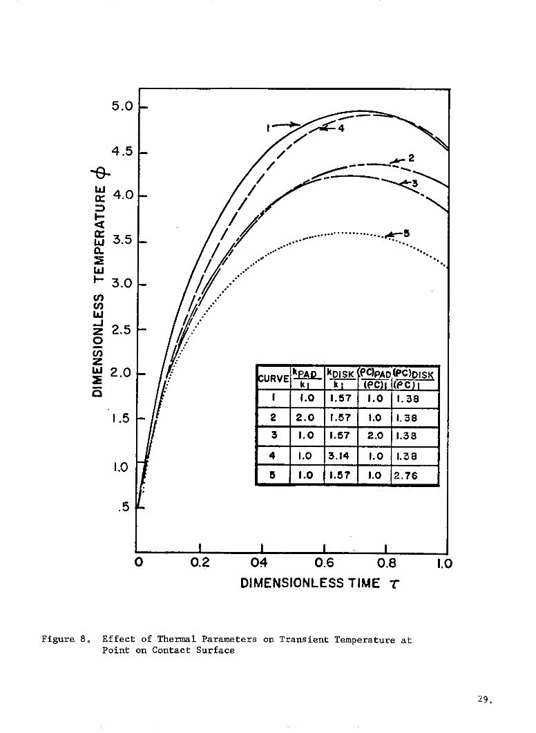
The results of these tests are shown in Figures 8-10 for three different
points inside the brake section. The reference values k1 and (pc)1 are, respect-
ively, thermal conductivity and (density X specific heat) of the conventional fric-
tion pad material. The melting point of the conventional friction material, Tp,is approximately 4.7 for the values of L and Qo used in these computations.
Figure 8 shows the effect of the different thermal parameters on the tempera-
ture at the contact surface (pt. A in Fig.2). It can be seen that the maximum de-
crease in surface temperature is achieved when the heat capacity of the disk ma-
terial is doubled (curve 5), with a doubling of the heat capacity of the pad
(curve 3) being next most effective in reducing surface temperature. An increase
in the thermal conductivity of the materials is not quite as effective in reducing
contact surface temperatures (curves 2 and 4). The changes in conductivity caused
significant reductions in surface temperature early in the braking cycle, but the
magnitude of the reductions decreased later in the cycle. The temperature decrease
resulting from increasing the specific heat, on the other hand, remained undiminished
throughout the braking cycle.
28.
5.0I -4
4.5 - 2
4.0-
/ .......... .. .II / .
3 .5 .....a.
- 3.0u,
w-jz 2 .50
z -J2.0 URV kP kDISK PCPAD(PC)DISK
kL k C) I((e C)1 1.0 1.57 1.0 1.38
1.5 - 2 2.0 1.57 1.0 1.38
3 1.0 1.57 2.0 1.38
4 1.0 3.14 1.0 1.38L.O
5 1.0 1.57 1.0 2.76
.5
I I I I0 0.2 04 0.6 0.8 1.0
DIMENSIONLESS TIME T
Figure 8. Effect of Thermal Parameters on Transient Temperature atPoint on Contact Surface
29.
5.0 -
4.5 2
4.0
w 3 .5 50 . 0........
S3.0-U,
: -S2.5
2.0
1.5 - C.URVE k I (C QISK
SI 1.0 1.57 1 1.0 I. 38
1.0 - 2 2.0 1.57 1.0 1.38
3 1.0 1.57 2.0 1 38
.5 - 4 1.0 3.14 1.0 1.38
S5 1.0 1.57 1.0 2.76
0 .2 .4 .6 .8 K
DIMENSIONLESS TIME T
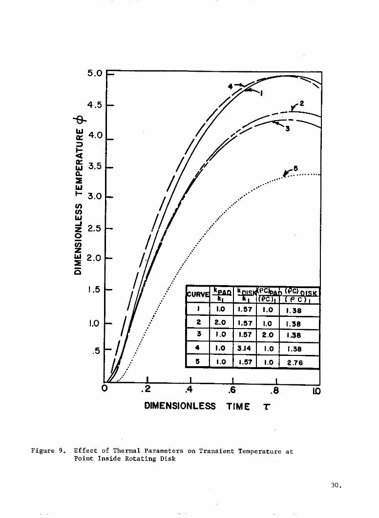
Figure 9. Effect of Thermal Parameters on Transient Temperature atPoint Inside Rotating Disk
30.

5.0
4.5
-e- .
cr 4.0- %P ,L k jLLLe i wiSI 1.0 1.57 1.0 1.30
2 2.0 1.57 1.0 1.38-3.5
C. 3 1.0 1.57 2.0 1.30
W 4 1.0 3.14 1.0 1.30 2
- 3.0 - 5 1 , 1.57 I.0 2.76
2.5 0
J 2.0
.5 .
0 .2 .4 .6 .8 1.0DIMENSIONLESS TIME T
Figure 10. Effect of Thermal Parameters on Transient Temperature atPoint Inside Friction Pad
31.

The effects of the thermal property changes on the temperatures inside the
rotating disk (point B in Fig.2) and inside the friction pad (pt. C) are shown
in Figures 9 and 10, respectively. It can be seen that increasing the thermal
conductivity of the disk material causes a temperature increase in the disk, at
least through most of the braking cycle, while an increase in heat capacity of
that material.causes a decrease in temperature. The same effects on the tempera-
ture at a point inside the pad result from changing the pad material properties.
The temperature at both points showed a decrease when either conductivity or
specific heat of the opposite material was increased. As with the surface tem-
perature, the greatest temperature decreases were brought about by a doubling of
the heat capacity of the disk material with a doubling of the pad material heat
capacity being next most effective.
As was mentioned earlier, the above results were found for fictitious com-
binations of material properties. Data for real materials yields similar results,however, as can be seen from Table 1. This set of tests, which was carried out
to provide information for use in a brake material evaluation (Ref.22), shows the
transient temperature variation at a point on the friction surface (pt. A in Fig.2)
under rejected takeoff conditions. The contact area was again kept constant by
setting a = 0 in order to eliminate the effects of thermal deformation and wear.
The materials investigated are listed in Table 1 in order of increasing heat
capacity (pc). It can be seen that, in general, an increase in pc leads to a de-
crease in surface temperature, as was found earlier from Figure 8. Although heat
capacity seems to have a greater influence on surface temperatures, thermal con-
ductivity is also important, as pointed out by the data for copper.
From our results it is apparent that the thermal properties of brake materials
are very important if low brake temperatures are desired. The specific heat seems
to be especially important since nearly all of the generated heat remains in the
brake components during the short braking cycle and the components must, therefore,be able to absorb large quantities of heat without rising to excessive temperatures.
The thermal conductivity is also important so that the generated heat can be con-
ducted rapidly away from the friction surface.
The ideal brake material would have a high value for both pc and k, and would
also have a high melting temperature and exhibit all the other characteristics
desirable for such applications (Ref.22). Such a material does not exist, however,
32.

TABLE 1
TRANSIENT TEMPERATURE AT POINT A ON FRICTION SURFACEFOR DIFFERENT FRICTION PAD MATERIALS
Friction Pad PC k Melting Temperature cp at Point AMaterial (pC) k Point 1 2 T
1 1 Pm T T - =1
Zirconium .71 4.7 5.45 1.71 2.73 3.09
Conventional
Friction Material 1.0 1.0 2.92 1.69 2.58 2.87
Molybdenum 1.15 7.5 7.65 1.47 2.33 2.64
Aluminum 1.18 11.8 1.98 1.42 2.26 2.55
Copper 1.35 21.0 3.2 1.33 2.09 2.38
Beryllium 1.37 7.8 3.78 1.35 2.14 2.43
Cobalt 1.44 3.7 4.41 1.34 2.14 2.42
Nickel 1.53 4.9 4.29 1.30 2.07 2.39
Cobalt-Base
Superalloy 1.75 1.64 3.8 1.32 2.02 2.26
Notes:
1. For all cases, rotor material was medium-carbon alloy steel with
pc = 1.38 and k = 2.43.PC1 k1
2. Reference values are k1 = 18.84 Joules/m sec2K; (pc) =2.57 x10 6 Joules/m 3 K.Tkl
3. Dimensionless variables are p . x 10 and T = t/t.
33.

and compromises must be made when choosing materials for brake applications. The
results of this section indicate that when such a material is chosen, the thermal
parameters should be optimized so that low surface temperatures will be produced.
The results of Figures 8-10 also seem to show that the amount of heat conducted
away from the friction surface into a given material depends, not only on the con-
ductivity of that material relative to the conductivity of the opposing material,but also on its relative ability to absorb heat (specific heat). Any partitioning
of the generated heat must be a function of both thermal parameters.
4.4 Effect of Component Thickness on Brake Temperatures
In this section we will investigate the effect of the thickness of the brake
components on the temperature distribution in an aircraft disk brake. We will again
eliminate the effects of thermal deformation and wear by setting c = 0 for all brake
materials. Otherwise all material properties will be those of the conventional
Boeing 747 brake materials and those properties will remain constant throughout the
test series.
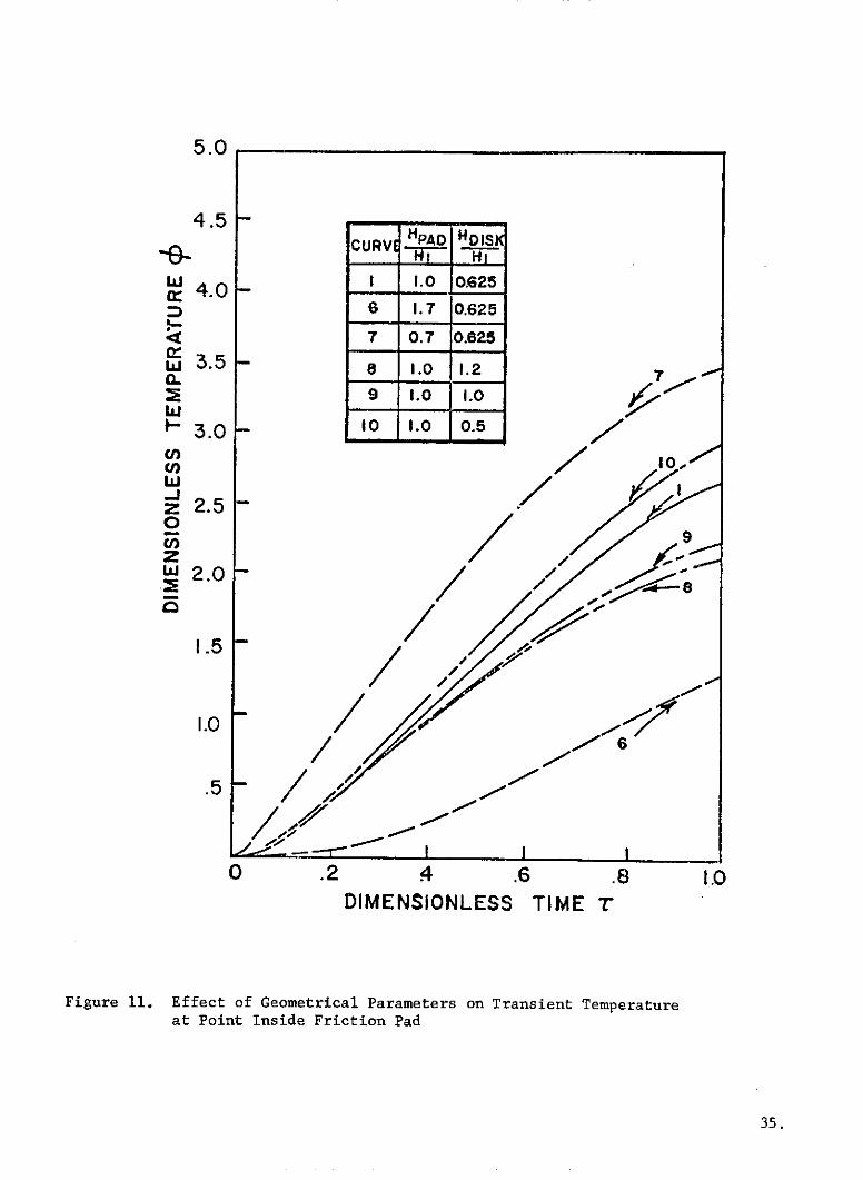
The temperature variation was plotted for the same three points considered in
the previous section (one point inside friction pad, one point inside disk, one
point on friction surface) and the results are shown in Figures 11-13. The pad
thickness and disk half-thickness are given by Hpad and Hdisk- respectively, with
the thickness of a conventional Boeing 747 friction pad being H1.
Figure 11 shows the effect of pad and disk thicknesses on the temperature at
a point inside the pad. It is seen that a decrease in pad thickness results in a
higher temperature at point C (curve 7) while an increase in thickness leads to a
decrease in temperature (curve 6). This would be expected since the distance of
point C from the friction surface changes as the pad thickness changes. In addi-
tion to these changes, it is also seen that variations in the thickness of the disk
affect the temperature inside the friction pad, with an increase in the disk thick-
ness causing a decrease in the temperature at point C (curves 8 and 9), and a de-
crease in disk thickness bringing about an increase in pad temperature (curve 10).
This effect seems to indicate that the portion of the generated heat that enters
the pad is affected by the volume of the disk.
34.
5.0
4.5CURVE HPAD IHDIS
WI 1.0 0.625S4.06 1.7 0.625
1-
7 0.7 0.625
3.5 - a 1.0 1.2
2 9 1.0 1.0
- 3.0 Ito .o o.s
z 2.5o 9
zw 2.0 -
1.5 -
.5 /
0 .2 4 .6 .8 1.0DIMENSIONLESS TIME T
Figure 11. Effect of Geometrical Parameters on Transient Temperatureat Point Inside Friction Pad
35.

5.5 -
5.0 -
4.5 -
S4.0- /
w 2.5-n
2 /
m 2.0 /
1.0
8 1.0 1.2
---
./9 1.0 1.0.5 I0 1.0 0.5
I I I
0 .2 .4 .6 .8 I1DIMENSIONLESS TIME T
Figure 12. Effect of Geometrical Parameters on Transient Temperature atPoint Inside Rotating Disk
36.

5.5
5.0
4.5
4.0
-.5 -//
w- 3.0
wz 2.50l) URVE A HDISK
Z 8S2.0 - I 1.0 0.625
6 1.7 0.625
1.5 - 7 0.7 0.625
8 1.0 1.2
9 1.0 I10
I.0 0o o1.0 o.5
.5
I I I I
0 0.2 0.4 0.6 0.8 1.0
DIMENSIONLESS TIME T
Figure 13. Effect of Geometrical Parameters on Transient Temperature atPoint on Contact Surface
37.

Looking next at Figures 12 and 13 one can see the effect of thickness on the
temperature at point B inside the disk and at point A on the contacting surface.
Curves 8, 9, and 10 produce results similar to those mentioned above, with an in-
crease in disk thickness resulting in a lower temperature at both points B and A
and a decrease in thickness resulting in a higher temperature. The magnitude of
these changes is greater inside the disk (Fig.12) than on the contacting surface
(Fig.13), as one might expect.
The effect of pad thickness on disk and surface temperatures seems to differ
from our other results. As can be seen from curves 6 and 7, a decrease in pad
thickness produces a slight decrease in temperature at both points B and A. The
reason for this phenomenon seems to be that the friction pad under investigation
consists of a friction material with rather low specific heat and conductivity,
surrounded by a steel jacket with higher thermal properties. If the friction pad
wears and the pad gets thinner, less low-conductivity friction material lies be-
tween the steel jacket and the friction surface, enabling the jacket to absorb more
of the generated heat. This phenomenon is peculiar to configurations such as that
investigated and would not be encountered in the case of a single-material stator.
From the above results one can see that the geometry of the brake components
has a considerable effect on the temperature distribution in the brake. If low
surface temperatures are desired, it would be advantageous to increase the volume
of the heat sink, which in our case is the disk. It seems that by doing so, one
increases the capacity of the heat sink to absorb heat and this allows more of the
generated heat to flow into the sink material. Although there are exceptions, as
with our pad configuration, it seems that the transient partitioning of generated
heat is generally affected by the relative volumes of the contacting bodies, as
well as by the thermal properties discussed in the previous section, and any parti-
tioning relationship for sliding bodies of finite thickness should show this
dependence.
38.

SECTION 5
CONCLUSIONS
(1) The thermoelastic instabilities that cause changes in the areas of actual
contact between sliding bodies can be modeled analytically by use of the finite
element method. This process of contact area change can be briefly described as
follows: Non-uniform thermal deformation of the contact surface causes concentra-
tion of contact at areas of largest deformation, resulting in higher temperatures
being generated in those areas and more concentration of contact, until the stress
level at the concentrated contact is so high that wear occurs and the contact
shifts to another area, where the process repeats.
(2) Modeling of the wear process by using a wear criterion based on a critical,
temperature-dependent distortion energy results in prediction of wear rates for a
caliper disk brake that are the same order of magnitude as the wear rates deter-
mined experimentally.
(3) The transient temperature distribution in the components of a disk brake
can be determined more accurately by use of this thermoelastic analysis than by an
analysis that assumes constant contact conditions.
(4) The thermoelastic analysis described here is not as practical when the
heat energy generated at the sliding surface is so high that near-melting-point
temperatures and very high wear rates are produced at the concentrated contacts.
(5) The partitioning of the heat generated at the interface between two sliding
bodies depends on the conductivity, density, specific heat, and volume of the two
bodies.
(6) Lower temperatures in a disk brake assembly can be attained by increasing
the conductivity, the volume and, especially, the heat capacity of the heat sink
component. The development of new brake materials and improved component designs
promises to be a major way to attain lower brake temperatures, which are very
desirable from the standpoint of improved brake performance, decreased brake wear,
and improved aircraft safety.
39.
APPENDIX A
DEVELOPMENT OF FINITE ELEMENT EQUATIONS FOR THERMAL ANALYSES
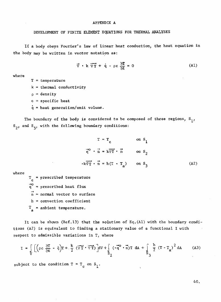
If a body obeys Fourier's law of linear heat conduction, the heat equation in
the body may be written in vector notation as:
-aTk + q - pc T = 0 (Al)
where
T = temperature
k = thermal conductivity
p = density
c = specific heat
q = heat generation/unit volume.
The boundary of the body is considered to be composed of three regions, Sl,
S2P and S3, with the following boundary conditions:
T = T on S1
oq , n = kVT n on S 2
-4 -4
-kVT * n = h(T - Ta) on S 3 (A2)
whereTc = prescribed temperature
-~oq = prescribed heat flux
-4
n = normal vector to surface
h = convection coefficient
Ta = ambient temperature.
It can be shown (Ref.13) that the solution of Eq.(A1) with the boundary condi-
tions (A2) is equivalent to finding a stationary value of a functional I with
respect to admissible variations in T, where
I = pc - - )T+.~ (v VT) dV+J (-q - n)T dA + (T-Ta) dA (A3)
V S 2 S3
subject to the condition T = Tc on S I.
40.

If the body (or system) under investigation is composed of N finite elements,then for the body we have:
N e.
I= Ii=l
and our variational principle is
N e.
6I = 81 = 0 (A4)i=l
for admissible variations in T.
We will now form the variation SIe for a ring element of triangular cross
section for use in an axisymmetric thermal analysis. For such an element we assume
a linear temperature distribution in the element of the form:0T r e
T = TL 1 + T2L2 + T3L3 = (Le T T2 (A5)
T 3
where 1,2,3 are the nodes of the element and the T. are the temperatures at those
nodes.
eIt can be easily shown, using area coordinates, that the shape functions L.,
for the element are given by:
e 1 1L = 2A [(rz k -r k zj ) + r(z - Zk) + z(r k - rj)] = [a +b r+ d.z] (A6)
where A is the cross-sectional area of the triangular element, and i, j, k == 1, 2, 3 (cyclic permutation).
If we write the vector quantities in (A3) in cylindrical coordinates, allow
the material to have transversely isotropic heat conduction properties (kr / kz),
and use (A5) and (A6), we find that the first variation of I for a triangular ring
element is given by
61e = [S((P c L eTT+ e T'8e at- q LeT 2 [B]+[C] T2 dV - ( q-o n)[LeT dA
V 4A T SA
T T Ie8T
+ j h(LeT T2 - Ta){Le}T dA] S6T 2 (A7)
3 T3 8T 341
41

where B.. = k b.b. and C.. = k d d..ij r i l 1j z i j
In order to take care of the time dimension, let us divide the total time
interval of interest into small time increments and proceed in a step-by-step
procedure. We will assume that the time increments are small enough so that the
variation of temperature with time during the increment may be approximated by
Tt t +T- + n ) t(A8)t t-Atvt I t-At at 2(
We now sum the 61e given in (A7) over all elements and apply the variational
principle (A4) at both the beginning of the increment (t-At) and the end of the
increment (t). Using (A8) we get the following expression for the set of nodal
temperatures T. at the end of the increment that satisfy our field equation (Al)
with boundary conditions (A2)
k[G] + -AL [R](T.t t [R] - [G](T)t- - F) - Ft- (A9)
where N
Gi h L.L. dA + 1[k + k d.d.] j dV)i 1 j 4A 2 3 e 3
k=l S3 V ek
N
F. = -q L. dV - hT L. dA - q n L. dA
k=l V S3 S2 ek
N N T
R.. = I (pc L.L. dV)e (T T 2k=l V k=l T
Defining:
[TS] [G] + [R]At
and
(FT3 (t-- [R] - [G])( tAt - (Ft - FtA
we may write (A9) as
[TS](Tit = (FTI. (A10)
42.

APPENDIX B
FLOW CHART FOR SOLUTION OF SLIDING-CONTACT PROBLEM
Start
Read and printinput data
Generate finite element mesh
For each element:
Form: [Ne], [Be], [Ke], [K'e , pe), [Re], [Ge], [G e]
Store: [Be], [Be] T[De], (2/At)[Re] Ge1Add: [Ke ] to [ST], [Ge ] + (2/At)[R e ] to [TS]
lsNFREE > 1? Calculate stressesc bdisplacements, and
ELoop on elements contact areas
Is element on boundary?(Y pec (see nextYes No
page)
Use hTa and q in (A9) todetermine contribution to (F)
Is element a contacting source element?
Yes N o
Use Pein (3) to calculatecontribution to (F)
Use [T t-At, (F3tA t and [F3 to determine
contribution to (FN) using (A9)
End loop on elements
Apply prescribed temperatures (if any)
SSolve matrix Eq.(1) for (T t
Calculate AT e for each element
iNoHas elapsed time reached maximum?
Yes
43.

Calculation of Stresses, Displacements, and Contact Areas
from main program
(preceding page)
For each element:
Calculate element contribution to (FN}
Apply prescribed displacements
-Solve Eq.(5) for incremental displacements [DIS)
For each element: Correct prescribedUse (DISI to find (fael displacementsAdd [DIS3 to (uo3 and (AOeJ to (Col
Integrate (al along plane and determineF tot
Is Ftot = Fap l No
! Yes
Loop on elements
tNoIs element a source element?
Yes
CIs element in contact? NoYes $
Has element lost contact (Pe< 0)? Determine if element hasJNo Yes resumed contact
D eeDetermine (AGNo .Yes
Calculate amount ofwear using (12)
Determine (o )
Determine contribution to [FN} using (Aa } I
Change [ST] and [TS] End loop on elementsusing [K r e ] and [G'e]
YesHas change occurred on contact surface?
No
Set NFREE = 1
Return to main program
(preceding page)
44.

NOMENCLATURE
a. - geometric constants used in shape functions [Eq.(A6)]1
b. - geometric constants used in shape functions [Eq.(A6)]1
c - specific heat
c1 - reference value of specific heat
d. - geometric constants used in shape function [Eq.(A6)1
f - coefficient of friction
h - thickness of source elemente
h - film heat transfer coefficient (convection)
k - thermal conductivity
k I - reference value of thermal conductivity
I - average radius of friction surface
A. - inside radius of friction surface1
A - outside radius of friction surfaceo
n - outer normal vector to boundary surface
q - heat generation rate/unit volume
q - prescribed heat flux
r - outside radius of elemento
r. - inside radius of element
r - centroidal radius of element
t - time (measured from beginning of braking)
At - length of time increment
tf - elapsed braking time when aircraft comes to stop
lUo) - matrix of nodal displacements before increment
w - displacement in z-direction
w - thickness of worn material from one wear occurrencew
45.

A - cross-sectional area of triangular finite element
A - contacting area of stator source elementp
AD - contacting area of rotor source element
[B] - matrix defined in Eq.(A7)
[C] - matrix defined in Eq.(A7)
[D] - constitutive relationship matrix for elastic elements [Eq.(7)]
[D'] - constitutive relationship matrix for fissured elements [Eq.(6)]
(DIS) - matrix of incremental nodal displacements
E - modulus of elasticity
(F) - matrix defined in Eq.(A9)
(FTI - matrix of thermal loads [Eq.(A10)]
(FNI - matrix of nodal loads
(FTI - matrix of nodal thermal stress loads
(FF - matrix of nodal body force loads
(FS3 - matrix of nodal surface traction loads
F - force applied to brake by hydraulic pistonsappl
Fto - resultant force acting on friction surface
[G] - matrix defined in Eq.(A9)
Hpad - thickness of stator friction pad
Hdisk - half-thickness of rotor disk
H1 - reference value of stator pad thickness
I - functional in variational principle for thermal analysis
J - mechanical equivalent of heat
J2 - second invariant of stress deviator tensor
[Ke ] - element stiffness matrix
(L3 - matrix of shape functions
46.

AM - mass of worn material
Mo - original mass
N - number of finite elements in domain
P - pressure acting normal to friction surface in source element
(PI - matrix of concentrated nodal forces
(p} _- matrix of nodal forces used in stress transfer process
Q - heat generation rate
Qo - initial rate of heat generation
[R] - matrix defined in Eq.(A9)
[STI - system stiffness matrix
[TS] - thermal "stiffness" matrix [Eq.(A10)]
T - temperature (uniform initial temperature E 0)
(Ti) - matrix of nodal temperatures
T - ambient temperaturea
T - prescribed temperature
V - volume of finite element
W - critical value of J2 for wear to occur
o - coefficient of thermal expansion
B - included angle of ring sector
6 - displacement of midplane A-A
(el - elastic strain matrix for element
(Cw - strain occurring in element during wear
8 - dimensionless time t 103
i
e a - dimensionless time for annular analysis
v - Poisson's ratio
eT - potential energy functional for element
47.

p - density
(pc)l - reference value of density X specific heat
(al - stress matrix for element
(ae) - elastic stress matrix for element
1o' - stress in element after wear or fissuring
(ACao - stress to be transferred from worn or fissured element
(aoI - stress in element before wear
(cw - stress relieved in element by one wear occurrence
a - yield stress
ozz - z-component of stress in element if no wear had occurred
T - dimensionless time m t/tf
Trz T z - shear stress components
T k3p - dimensionless temperature - X 103
Qo
cm - dimensionless melting temperature
w - angular deceleration of wheel
- initial angular velocity of wheel
Subscripts not defined above
r,e,z - cylindrical coordinates
i - node number
Superscripts
e - refers to one element
48.

REFERENCES
1. Blok, H., "Theoretical Study of Temperature Rise at Surfaces of Actual Contact
under Oiliness Lubricating Conditions," Proc. Gen. Discussion on Lubrication,
Inst. Mech. Engrs., London, Vol.2, pp.2 2 2-2 35, 1937.
2. Jaeger, J.C., "Moving Sources of Heat and the Temperature at Sliding Contacts,"
Proc. of the Roy. Soc. of New South Wales, Vol.76, pp.203-2 2 4, 1942.
3. Ling, F.F. and Pu, S.L., "Probable Interface Temperatures of Solids in Sliding
Contact," Wear, Vol.7, No.1, pp.23-34 , 1964.
4. Ling, F.F., "On Temperature Transients at Sliding Interface," Trans. ASME,
J. Lub. Tech., Series F, Vol.91, pp.397-405, 1969.
5. Parker, R.C. and Marshall, P.R., "The Measurement of the Temperature of Sliding
Surfaces with Particular Reference to Railway Brake Shoes," Proc. Inst. of
Mech. Engrs., Vol.158, pp.209- 2 29, 1948.
6. Barber, J.R., "Thermoelastic Instabilities in the Sliding of Conforming
Solids," Proc. Roy. Soc., A, Vol.312, pp.381-394 , 1969.
7. Santini, J.J., "Effect of Design Factors on the Generation of Surface Tempera-
tures in a Sliding System," D. Eng.Dissertation, Rensselaer Polytechnic
Institute, June 1973.
8. Korovchinski, M.V., "Plane-Contact Problem of Thermoelasticity during Quasi-
Stationary Heat Generation on the Contact Surfaces," Trans. ASME, J. Basic
Eng., Series D, Vol.87, pp. 811- 817, 1965.
9, Dow, T.A. and Burton, R.A., "Thermoelastic Instability of Sliding Contact in
the Absence of Wear," Wear, Vol.19, pp.315-3 2 8 , 1972.
10. Newcomb, T.P., "Temperatures Reached in Disk Brakes," J. Mech. Eng. Sci.,
Vol.2, No.3, pp.167-177, 1960.
11. Fazekas, G.A.G., "Temperature Gradients and Heat Stresses in Brake Drums,"
SAE Trans., Vol.61, pp. 279- 3 0 8, 1953.
12. Chichinadze, A.V., "Temperature Distribution in Disk Brakes," Friction and
Wear in Machinery, Trans. ASME, Vol.15, pp.259-275, 1962.
13. Visser, W., "A Finite Element Method for the Determination of Non-Stationary
Temperature Distribution and Thermal Deformations," Proc. of the First Con-
ference on Matrix Methods in Structural Analysis, Wright-Patterson AFB, Ohio,
pp.9 2 5 -9 2 8, 1965.
14. Zienkiewicz, O.C., The Finite Element Method in Engineering Science, McGraw-
Hill Publishing Co. Ltd., 1971.
49.
15. Kennedy, F.E., "Analysis of Nonlinear Contact Problems by the Finite Element
Method," Ph.D. Dissertation, Rensselaer Polytechnic Institute, 1972.
16. Zienkiewicz, O.C., Valliappan, S., and King, I.P., "Stress Analysis of Rock
as a 'No Tension' Material," Geotechnique, Vol.18, pp.5 6 -6 6, 1968.
17. Kragelskii, I.V., Friction and Wear, Butterworths, Inc., 1965.
18. Rabinowicz, E., Friction and Wear of Materials, John Wiley & Sons, Inc., 1965.
19. Archard, J.F., "Wear," in Proc. of Interdisciplinary Approach to Friction and
Wear, NASA, 1968.
20. Lancaster, J.K., "The Influence of Temperature on Metallic Wear," Proc. Phys.
Soc. of London, B 70, pp.11 2-118, 1957.
21. Mac Gregor, C.W., ed., Handbook of Analytical Design for Wear, Plenum Press,
1964.
22. Peterson, M.B. and Hol T.L., "Consideration-of Materials for Aircraft Brakes,"
NASA CR-121116, April 1972.
50.