
NASA CONTRACTOR · NATIONAL AERONAUTICS AND SPACE ADMINISTRATION ... to the launch pad, ... 190 200...
134
NASA CONTRACTOR REPORT 40 04 ASSESSMENT OF SPACE VEHICLE AEROACOUSTIC-VIBRATION PREDICTION, DESIGN, AND TESTING bY Harry Himelb Zuu Space Division of North Americun Rockwell Corporation C. Myron Fder McDonnell Doughs Astronuutics Compuny - Western Division Terry D. Schzrton Bolt Berunek und Newmun Inc, Prepared by McDONNELL DOUGLAS ASTRONAUTICS COMPANY Huntington Beach, Calif. fir LangZey Research Center NATIONAL AERONAUTICS AND SPACE ADMINISTRATION WASHINGTON, D. C. JULY 1970 https://ntrs.nasa.gov/search.jsp?R=19700024578 2018-07-07T11:10:01+00:00Z
Transcript of NASA CONTRACTOR · NATIONAL AERONAUTICS AND SPACE ADMINISTRATION ... to the launch pad, ... 190 200...

N A S A C O N T R A C T O R
R E P O R T 40 04
ASSESSMENT OF SPACE VEHICLE AEROACOUSTIC-VIBRATION PREDICTION, DESIGN, AND TESTING
bY Harry Himelb Zuu Space Division of North Americun Rockwell Corporation
C. Myron F d e r McDonnell Doughs Astronuutics Compuny - Western Division
Terry D. Schzrton Bolt Berunek und Newmun Inc,
Prepared by McDONNELL DOUGLAS ASTRONAUTICS COMPANY Huntington Beach, Calif. f i r LangZey Research Center
NATIONAL AERONAUTICS AND SPACE ADMINISTRATION WASHINGTON, D. C. J U L Y 1970
https://ntrs.nasa.gov/search.jsp?R=19700024578 2018-07-07T11:10:01+00:00Z

TECH LlQRARY KAFB, NM
/" NASA CR-1596
1
!, I
I ASSESSMENT OF SPACE VEHICLE AEROACOUSTIC-VIBRATION
PREDICTION, DESIGN, AND TESTING
By Harry Himelblau
Space Division of North American Rockwell Corporation
C. Myron Fuller
McDonnell Douglas Astronautics Company - Western Division
and
Terry D. Scharton
Bolt Beranek and Newman Inc.
I
i i .,//
Prepared under Contract No. NAS 1-6024 by McDONNELL DOUGLAS ASTRONAUTICS C0,MPRIW - WESTERN-DIVISION
Huntington Beach, Calif.
I for Langley Research Center
NATIONAL AERONAUTICS AND SPACE ADMINISTRATION
For sale by the Clearinghouse for Federal Scientif ic and Technical Information Springfield, Virginia 22151 - CFSTI price $3.00


ABSTMCT
This document provides a gene ra l su rvey o f t he f i e ld o f space -veh ic l e s t ruc tu ra l v ibra t ion , which is induced by acoust ic and aerodynamic noise and cer ta in mechanica l exc i ta t ion . The fundamental sources and mechanisms of the vibrat ion are i d e n t i f i e d ; a n a l y t i c a l methods o f v ibra t ion pred ic t ion are descr ibed . L a b o r a t o r y , f i e l d , and f l i g h t t e s t i n g are discussed, including problems of q u a l i f i c a t i o n - and acceptance- tes t se lec t ion . Al though the advantages and l imi ta t ions o f the var ious ana ly t ica l and exper imenta l methods are as ses sed , s p e c i f i c methods are seldom recommended because select ion of the methods i s o f t en i n f luenced by the c i r cums tances o f t he pa r t i cu la r app l i ca t ion , and by economic and scheduling factors.
A l i s t of program objectives is f u r n i s h e d o u t l i n i n g a genera l p rocedure for e n s u r i n g t h e s t r u c t u r a l i n t e g r i t y and opera t iona l per formance of l aunch vehic les and spacec ra f t exposed t o s t ruc tu ra l v ib ra t ion . Then, t o e n s u r e t h a t t h e s e ob jec t ives are s a t i s f i e d , g e n e r a l recommendations are made f o r implementing the var ious des ign , ana lys i s ' , and tes t ing t echniques dur ing var ious phases of vehicle development.

6.
7.
5 .1 . I . 2 Applicability to Space-Vehicle Structures
5.1.1.3 Assessment
5.1.2.1 Test Classification and Philosophy 5.1.2.2 Test Facilities 5.1.2.3 Qualification-Test Requirements and
Their Selection 5.1.2.4 Alternatives for Insufficient-Force
Capacity 5.1 .2.5 Accep tance-Test Requirements and
Their Selection 5.1.2.6 Design-Development Test Selection 5.1.2.7 Assessment
5.1.3.1 Test Facilities 5.1.3.2 Comparison with Vibration Tests 5.1.3.3 Test Requirements and Their Selection 5.1.3.4 Assessment
5.1.2 Vibration Tests
5.1.3 Acoustic Tests
5.1.4 Combined Environmental Testing 5.2 Field Testing 5.3 Flight Testing
OBJECTIVES OF SPACE-VEHICLE DESIGN DEVELOPMENT FOR VIBRATION
RECOMMENDATIONS FOR IMPLEMENTING VARIOUS DESIGN, ANALYSIS, AND TESTING TECHNIQUES
7.1 Preliminary Design Phase 7.2 Early Development Phase 7.3 Last Development Phase 7.4 Flight-Test Phase
8. CONCLUDING REMARKS
APPENDIX Internal Force-and-Moment Vibration-Response Equations for Structures Exposed to Aeroacoustic Noise
5 4 60 61 61 65
70
79
80 81 81 81 81 83 85 87 89 90 93
97
99
99 102 102 103
105
107
REFElZENCES
v i i i
115

FIGURES
4
5
6
7
8
9
10
11
12
13
14
15
16
1 7
18
19
20
21
Vibration measured on the S - I V B s t age o f t he up ra t ed Sa tu rn I space veh ic l e du r ing Apo l lo -Sa tu rn f l i gh t SA-203
Rocket -engine acous t ic no ise sources and d i rec t iv i ty pa t te rns t o t h e s p a c e v e h i c l e d u r i n g l i f t o f f o r s t a t i c f i r i n g
2
13
Sch l i e ren shadowgraph of the aerodynamic f low f ie ld of an Apollo-Saturn model i n a wind tunnel, showing turbulence, shock waves, and separated f low , 15
A lumped-parameter model of a s e c t i o n of a space vehic le 18
Long i tud ina l c ros s -co r re l a t ion of aerodynamic noise during the t r a n s o n i c p e r i o d f o r two microphones located 40 i n . a p a r t on t h e e x t e r n a l s u r f a c e of t he Apo l lo s e rv i ce module 21
Mate r i a l -damping p rope r t i e s fo r va r ious ae rospace s t ruc tu res 23
Diagrammatic f o r d e t e r m i n i n g v i b r a t i o n r e s p o n s e t o m u l t i p l e sources 25
Fa t igue cu rve fo r a typ ica l aerospace mater ia l under s inusoida l loading 26
Rat io of the incomplete to the complete gamma f u n c t i o n ( O ~ t j ~ 5 ) 28
Rat io of the incomplete to the complete gamma func t ion (02tj250) 29
P l o t of exponen t i a l cons t an t a0 t o be used i n d e t e r m i n i n g th re sho ld c ros s ing p robab i l i t y 31
I d e a l i z e d r e p r e s e n t a t i o n of a s imple space-vehic le s t ruc ture used fo r p red ic t ing t he space -ave rage r e sponse o f ex t e rna l and i n t e r n a l s t r u c t u r e a t h i g h e r f r e q u e n c i e s by s t a t i s t i c a l - e n e r g y a n a l y s i s 34
Space-average acous t ic acceptance for an idea l ized representa t ion o f space -veh ic l e ex t e rna l s t ruc tu re 35
Vib ra t ion - t r ans fe r func t ion be tween ex te rna l and i n t e r n a l s t r u c t u r e for an idea l i zed r ep resen ta t ion o f a space veh ic l e 36
Sound-pressure- leve l contours for the B-58 i n t h e 300- t o 600-Hz octave band 38
Vibration-prediction curves for Mahaffey-Smith and Bruat-Iiirnelblau methods i n t h e 300- t o 600-Hz oc tave . band 35
Comparison of narrow-band, one-third octave-barid, and octave--band spec t r a l ana lyses o f t he same random-vibration measuremenz 41
Cont r ibu t ion to t h e rms a c c e l e r a t i o n from mult intoial response as measurcd on s e v e r a l missiles 42
Vibration-prediction curves for Franken and Winter methods 44
V i b r a t i o n e f f i c i e n c y o f ae rodynamic no i se r e l a t ive t o acous t i c n o i s e 45
V i b r a t i o n - r e f e r e n c e s p e c t r a f o r B a r r e t t method on 50 f l i g h t measurements on t h e a f t s k i r t of Sa turn I fue l t anks 50
i x

22
23
24
25
26
27
28
29
30
31
32
33
34
35
36
37
38
39
40
A- 1
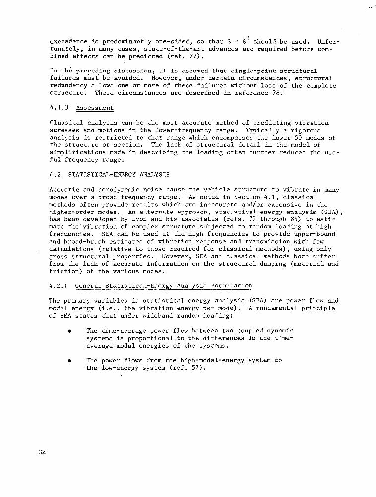
Compar ison of v ibroacous t ic - t ransfer func t ions for Snark missile s t r u c t u r e and two one-quarter scale models
S t r u c t u r a l d e t a i l s of t h e A p o l l o b o i l e r p l a t e service module
Comparison of Apollo b o i l e r p l a t e service module vibrat ion- s t ra in s p e c t r a
Comparison of Apollo boilerplate service module v i b r a t i o n - a c c e l e r a t i o n spectra
Comparison of v ib ra t ion - s t r a in spec t r a fo r p ro to type and mode l pane l s exc i t ed by j e t n o i s e
Labora tory v ibra t ion test of the Ranger spacecraf t
Labora tory v ibra t ion tests of t h e Gemini s p a c e c r a f t i n t h e v e r t i c a l and h o r i z o n t a l d i r e c t i o n s
Labora tory v ibra t ion tes t of the Surveyor spacecraf t
L a b o r a t o r y v i b r a t i o n - t e s t f a c i l i t y of t h e t h r u s t s t r u c t u r e and a f t s k i r t of t h e S - I 1 s t age , Sa tu rn V launch vehic le
Simplif ied schematic diagram of a typ ica l sys t em fo r pe r fo rming s i n u s o i d a l - v i b r a t i o n tests
Simplif ied schematic diagram of a typ ica l sys t em fo r pe r fo rming random v i b r a t i o n tests
Comparison of s p e c t r a l e n v e l o p e f o r 8 and 180 v i b r a t i o n measurements made on the ex te rna l pane ls o f the Apol lo s e r v i c e module d u r i n g a c o u s t i c t e s t i n g
Predicted vibrat ion spectrum and a f ive-segment spec t ra l envelope
Random v ib ra t ion - t e s t spec t rum cons i s t ing o f h igh - l eve l na r row band “spikes” superimposed on lower-level wideband spectrum
Acoustic test of t h e OGO spacec ra f t nea r t he d i scha rge nozz le of a l a r g e blowdown wind tunne l
Laboratory acoust ic test of t h e t h r u s t s t r u c t u r e , a f t s k i r t , and i n t e r s t a g e of t h e S - I 1 s t age , Sa tu rn V l a u n c h v e h i c l e i n a r eve rbe ran t test f a c i l i t y
Laboratory acoust ic t es t of t he Apo l lo spacec ra f t i n a p rogres s ive t es t f a c i l i t y
Comparison of v ib ra t ion spec t r a f rom acous t i c tes t w i t h f l i g h t and wi th o r ig ina l des ign and tes t requirement
Laboratory test f a c i l i t y f o r combined s u s t a i n e d a c c e l e r a t i o n - v i b r a t i o n - a c o u s t i c n o i s e - a l t i t u d e e n v i r o n m e n t a l t e s t i n g o f space-vehicle hardware
Forces and moments on a sha l low she l l e lement
60
6 2
6 3
6 3
6 4
66
67
68
6 9
70
71
76
7 8
79
82
83
8 4
8 8
91
107
X

' ASSESSMENT OF SPACE VEHICLE AEROACOUSTIC-VIBRATION
PREDICTION , DESIGN , AND TESTING
By Harry Himelblau, Space Division of North American Rockwell Corporat ion; C. Myron F u l l e r , McDonnell Douglas Astronautics Company - Western Divis ion; and Terry D. Scharton, Bol t Beranek and Newman Inc.
1 . INTRODUCTION
Various load and environmental conditions are a p p l i e d t o a s p a c e v e h i c l e , i t s subsystems, or assemblies during a mission - c o n d i t i o n s t h a t must be considered i n design and test to avo id mi s s ion f a i lu re o r deg rada t ion . Mechan ica l v ib ra t ion of t h e s t r u c t u r e is an ex t remely impor tan t condi t ion to be cons idered , s ince i t may c a u s e o v e r s t r e s s o r f a t i g u e of t h e s t r u c t u r e and equipment, or may cause malfunct ions of the equipment . This report restricts i t s e l f t o c o n s i d e r - a t i o n of t h e i n t e g r i t y o f s t r u c t u r e ; t h e p e r f o r m a n c e a n d s t r u c t u r a l i n t e g r i t y of equipment w i l l not be discussed herein. This document does however include a d i scuss ion of v i b r a t i o n d e s i g n and tes t requi rements for th i s equipment .
S t r u c t u r a l v i b r a t i o n i s o f t e n most predominant during the launch-and-ascent phase of f l igh t , and , depending upon the miss ion parameters and the s t ruc tura l conf igu ra t ion , may b e c r i t i c a l d u r i n g s p a c e f l i g h t a n d / o r a t m o s p h e r i c e n t r y and f l igh t . For example , f igure 1 shows the time h i s t o r y of the ins tan taneous v i b r a t i o n and the t ime-averaged rms v i b r a t i o n of a po in t on t h e S-IVB s t a g e of t he up ra t ed Sa tu rn I space vehicle , measured during the launch-and-ascent p h a s e . S i g n i f i c a n t v i b r a t i o n is obse rved du r ing l i f t o f f (T + 0 s e c ) , t h e t r a n s o n i c p e r i o d (T + 4 7 ) , t he supe r son ic pe r iod nea r t he occu r rence of t h e maximum aerodynamic pressure q (T + 63), and during S - I V B powered f l i g h t
(from T + 147 t o T + 4 3 4 ) . Vibra t ion spec t r a , i n t he fo rm o f acce l e ra t ion s p e c t r a l d e n s i t y vs f r equency p lo t s , are a l s o shown f o r l i f t o f f , t r a n s o n i c , and two pe r iods du r ing t he S-IVB powered f l i g h t . Depending upon t h e s t r u c t u r a l and aerodynamic conf igura t ion of the vehic le and the loca t ion of the v ibra t ion- moni tor ing po in ts on t h e s t r u c t u r e , t h e r e l a t i v e m a g n i t u d e of t h e v i b r a t i o n dur ing these per iods w i l l vary considerably f rom that shown i n f i g u r e 1 . Loca- t i ons nea r rocke t eng ines , fo r example , may undergo high vibrat ion during p ropu l s ion ope ra t ion , and r e l a t ive ly low v i b r a t i o n a t o t h e r time pe r iods . Loca t ions near the forward end of the vehic le , such as s p a c e c r a f t s t r u c t u r e s , may undergo h igh v ibra t ion dur ing t ransonic and/or supersonic per iods , and r e l a t i v e l y low v i b r a t i o n s a t o t h e r times. B e f o r e f l i g h t , v i b r a t i o n may be a p p l i e d t o t h e v e h i c l e , i t s subsys tems, o r assembl ies dur ing t ranspor ta t ion f rom the manufac turer to the l aunch pad , o r dur ing the s t a t i c f i r i n g of propul- s ion subsystems. Table I l is ts the mission phases and time periods where s i g n i f i c a n t v i b r a t i o n may possibly be observed.
max
Usua l ly , t he a t t empt i s made t o i n t e g r a t e t h e s e e n v i r o n m e n t s i n t o t h e v e h i c l e development program by means of design and test requirements . The s e l e c t i o n of these requi rements can be v i t a l to miss ion success and cos t , and i s the re - f o r e one o f the subjec ts of this report . Requirements which are too low,

INSTANTANEOUS ACCELERATION VS TIME HISTORY
CALIBRATIONS
1003 RMS ACCELERATION VS TIME HISTORY
10, r
1.. / / _"" -
- I I 1
,,,,,,,,,,,,,,,,,,,,,,,,,..,,,,.I 14 LIFTOFF MACH 1 14 aMAX lst STAGE I I 2nd STAGE IGNITION 2nd STAGE SHUTDOWN *I
I I I 0.1- ! I I I #
SEPARATION @I I' 10 0 10 20 30 40 50 60 70 80 90 100 110 120 130 140 150 160 170 180 190 200 210 220 230 330 340 350 360 370 380 390 400 410 420 430 440
TIME FROM RANGE ZERO ISEC)
RANDOM VIBRATION SPECTRA
1
10
10
1
10
10'
10
10
Figure 1.-Vibration measured on the S-IVB stage of the uprated Saturn I space vehicle during Apollo-Saturn flight SA-203. -

7 - , . ! j
TABLE I. -SIGNIFICANT STATIONARY VIBRATION ENVIRONMENTS
Prelaunch
Source of v i b r a t i o n
Acceptance t es t ing ~
Transpor t a t ion
Land
A i r
Sea
S t a t i c f i r i n g
Ground wind loads
~~
Type, source, and magnitude of v i b r a t i o n
Random a n d / o r p e r i o d i c v i b r a t i o n f rom labora tory v ibra t ion and/or a c o u s t i c test , i f used. Often high magnitude.
-
Random v i b r a t i o n f r o m t r u c k o r i n p l a n t d o l l y . P e r i o d i c v i b r a t i o n a l s o p o s s i b l e . Random and p e r i o d i c v i b r a t i o n f r o m r a i l r o a d t r anspor t a t ion . Usua l ly (bu t no t always) low magnitude and long du ra t ion .
Random v i b r a t i o n from j e t a i r c r a f t . P e r i o d i c v i b r a t i o n a l s o p o s s i b l e a d j a c e n t t o j e t engines . Per iodic v i b r a t i o n from p r o p e l l e r a i r c r a f t . Random and p e r i o d i c v i b r a t i o n from t u r b o p r o p a i r c r a f t . Random v i b r a t i o n from gust loading on a l l a i r c r a f t a t low frequencies. Usually (but not always) low magnitude and long duration.
Random and p e r i o d i c v i b r a t i o n from sh ips . Almost always low magnitude (except near fantai l ) and long dura t ion .
Random v i b r a t i o n from engine- induced acous t ic no ise . Of ten high magni tude. Direct ly t rans- mi t t ed random and /o r pe r iod ic v ibra t ion f rom engines , tu rbo- pumps, and auxi l iary equipment . Often high magnitude near source.
Random a n d / o r p e r i o d i c v i b r a t i o n a t low frequencies. Large l i m i t - a m p l i t u d e s e l f - e x c i t e d o s c i l l a t i o n may exceed l i m i t stresses i f system is uns t ab le .
3

TABLE I.-SIGNIFICANT STATIONARY V I B M T I O N ENVIRONMENTS - Continued
Mission phase
Launch and a scen t
Source of vibration
L i f t o f f
Wind loads - e n g i n e i n t e r a c t i o n
Aeroe la s t i c i n t e r a c t i o n and f l u t t e r
Pogo i n t e r a c t i o n
P rope l l an t s lo sh ing
Transonic buf fe t ing
Supe r son ic f l i gh t
Booster or upper- s t age ope ra t ion
_ _ _ _ _ _ ~ ~- ~”
Type, source and magnitude o f v ib ra t ion
Same as “static f i r i n g , ” e x c e p t v i b r a t i o n s p e c t r a may b e ‘ d i f f e r e n t . T r a n s i e n t o r p e r i o d i c v i b r a t i o n a t low frequencies. Divergent v i b r a t i o n i f s y s t e m is uns t ab le .
T r a n s i e n t o r p e r i o d i c v i b r a t i o n of s t ruc tura l assembl ies exposed t o aerodynamic flow. Divergent motion or l i m i t ampl i tude i f system i s uns t ab le .
T r a n s i e n t o r p e r i o d i c v i b r a t i o n a l o n g t h e l o n g i t u d i n a l v e h i c l e a x i s , f rom eng ine - th rus t o sc i l l a - t i o n s , c a u s i n g s t r u c t u r a l v i b r a t i o n of propuls ion assembl ies , and in turn causing propel lant-f low and e n g i n e - t h r u s t o s c i l l a t i o n s . Divergent motion or l i m i t ampli- tude i f sys tem i s uns t ab le .
T r a n s i e n t o r p e r i o d i c v i b r a t i o n a t low f requencies . Divergent i f s lo sh - s t ruc tu re -con t ro l sys t em is uns t ab le .
Random vibration from aerodynamic turbulence , somet imes ccampl i f iedyy by unstable shock waves. May c a u s e l o c a l o r o v e r a l l v e h i c l e vibrat ion. Often high magni tude, u s u a l l y a t forward end of vehicle, and sometimes transient.
Random v i b r a t i o n from aerodynamic t u r b u l e n c e i n r e l a t i v e l y s t a b l e
%ax magnitude, usual ly a t forward end of veh ic l e .
D i rec t ly t r ansmi t t ed random and/or p e r i o d i c v i b r a t i o n from engines , turbopumps, and auxiliary equipment. Often high magnitude near source.
~
boundary layer . Often high
4

TABLE I. -SIGNIFICANT STATIONARY VIBRATION ENVIRONMENTS - Concluded
Mission Phase
Launch and as cent (concluded)
~ -~
Space f l i gh t
Entry and atmospheric f l i g h t
Source o f v ibra t ion
Abort
~~ ~ ~~
Booster or upper- s t a g e o p e r a t i o n
Hypersonic f l igh t ~ ~
~ ~ ~~~~~
Decelera t ion loads
compared to the vehic le envi ronment ,
Type, source and magnitude o f v ib ra t ion
I f abor t rocke t is a f t , same as 'Booster or upper-s tage opera- t i o n . " I f a b o r t r o c k e t is forward, random vibra t ion f rom exhaus t f l ow. Poss ib l e i n t e r - ac t ion w i th o r i nc reased t ransonic buf fe t ing or boundary layer tu rbulence . Of ten h igh magnitude.
Same as under ' 'Launch and a scen t .
Random vibration from aerodynamic turbulence. Usual ly lower magnitude due to low d e n s i t y of boundary layer a n d , i n some cases, separated base f low.
Random v i b r a t i o n from r e t r o - rocket exhaust f low. Possible in t e rac t ion w i th hype r son ic turbulence. Random v i b r a t i o n from aerodynamic turbulence on parachute . Usual ly low magnitude.
~~
may jeopard ize the miss ion because of f a i lu re t o d i scove r des ign o r f ab r i ca t ion i nadequac ie s . On the o ther hand , excessive requirements may o b t a i n u n n e c e s s a r i l y h i g h r e l i a b i l i t y , a n d w i l l u sua l ly cause excess ive cos t s , s chedu le s l i ppage , and /o r excess ive veh ic l e weight.
By d e f i n i t i o n , s t r u c t u r a l v i b r a t i o n i s an osc i l la tory mot ion of a mechanical system relat ive t o a frame of reference, and is desc r ibed by c e r t a i n param- eters which are cons ide red t o be s t a t iona ry o r s t eady s ta te . Th i s v ib ra t ion may b e p e r i o d i c o r random, o r bo th . In space veh ic l e s , t h i s v ib ra t ion occu r s o n l y f o r d e f i n a b l e p e r i o d s of t i m e , and t h e r e f o r e i t i s t h e o r e t i c a l l y t r a n - s i e n t . However, t h e r e are several phases of t he mi s s ion where t he s ign i f i can t parameters def in ing the v ibra t ion ( such as t h e rms va lue ) are i n v a r i a n t o r are slowly changing with t i m e , as o b s e r v e d i n f i g u r e 1 . During these per iods , t h e e f f e c t s of t h e v i b r a t i o n on v e h i c l e i n t e g r i t y and performance may be determined adequately through the use of s t a t i o n a r y o r s t e a d y - s t a t e a s s u m p t i o n s i n t h e
t 5

v i b r a t i o n a n a l y s i s a n d test. The minimum p e r i o d t h a t a v i b r a t i o n may be considered as s t a t i o n a r y i s usua l ly dependen t on t he cha rac t e r i s t i c s o f t he s o u r c e , t h e s t r u c t u r a l c h a r a c t e r i s t i c s ( e s p e c i a l l y t h e d a m p i n g ) , t h e f a i l u r e and malfunction parameters, the accuracy desired, and sometimes common aerospace p r a c t i c e o r t h e i n v e s t i g a t o r ' s j u d g m e n t . V i b r a t i o n n o t c o n s i d e r e d s u f f i c i e n t l y s t a t i o n a r y o r s t e a d y s ta te should be considered as t r a n s i e n t , and i s n o t d i s - c u s s e d i n t h i s r e p o r t .
The s o u r c e s o f s p a c e - v e h i c l e v i b r a t i o n d i s c u s s e d i n t h i s r e p o r t are a c o u s t i c noise , aerodynamic noise , and mechanical ly induced exci ta t ion. The predominant f requencies of these sources usual ly cover a wide range, often from 10 Hz t o 10 kHz. I n most l o c a t i o n s on the vehicle , however , v ibrat ion above 2 kHz is seldom a c a u s e o f f a i l u r e , so t h a t t h e main emphasis i s d e v o t e d t o t h e range from 10 Hz t o 2 kHz. In t h i s f r equency r ange , subsec t ions of t h e v e h i c l e o f t e n v i b r a t e i n d e p e n d e n t l y o f o t h e r s u b s e c t i o n s ( e . g . , e n t i r e s t a g e s , i n d i v i d u a l sk in pane ls , longerons , s t i f feners , o r f rames , o r equipment items on s t r u c t u r e ) . A t l ower f r equenc ie s , t he veh ic l e u sua l ly v ib ra t e s "as a whole" i n i t s var ious la teral , l o n g i t u d i n a l , and t o r s i o n a l modes. O f t e n , t h i s b e h a v i o r b e g i n s t o d isappear before the 10 th la teral mode, whose r e sonan t f r equency u sua l ly va r i e s i nve r se ly w i th t he s i ze o f t he veh ic l e , In t he l a rge r space veh ic l e s , t h i s resonant frequency usually occurs below 25 Hz.
It shou ld be emphas ized t ha t t he i n i t i a l des ign of t h e s p a c e v e h i c l e is almost never made c o n s i d e r i n g s t r u c t u r a l v i b r a t i o n . Most v e h i c l e s t r u c t u r e s are i n i t i a l l y d e s i g n e d t o s t a t i c and sometimes thermal loads, with some overdesign f a c t o r s s p e c i f i e d f o r s u c h a d d i t i o n a l l o a d s as s t r u c t u r a l v i b r a t i o n . It w i l l be necessary to ascer ta in whether enough overdes ign has been incorpora ted to obv ia t e t he need t o r edes ign , cons ide r ing s t ruc tu ra l v ib ra t ion and o the r l oads and environments .
6

2. SYMBOLS
A area of s t r u c t u r e e x p o s e d t o s p a t i a l l y d i s t r i b u t e d
appl ied loading , i n . 2
a r a d i u s , i n .
Bp(x,Z) t r a n s f e r f u n c t i o n b e t w e e n i n t e r n a l f o r c e o r
moment a t l o c a t i o n x and appl ied force at l o c a t i o n Z
[CI damping ma t r ix , l b - sec / in .
Cp ( c , c ’ , f ) c o s p e c t r a l d e n s i t y f u n c t i o n of f l u c t u a t i n g p r e s s u r e s a t
frequency f and l o c a t i o n s 5 and 5 ’ , ( p s i ) /Hz 2
cr ( f ) r a t i o o f v ib ra t ion r e sponse t o app l i ed l oad ing a t frequency f
C
C a
ci
D
9
E
f
f C
fi’ f n
f r
s p e c i f i c h e a t ( s u b s c r i p t s d e n o t e medium) , in. /sec F o r
Btu i n . / l b sec2 OF
2 2 0
speed of sound i n a c o u s t i c medium, i n . / s e c
speed of l o n g i t u d i n a l waves i n a p l a t e o r s h a l l o w s h e l l
( s u b s c r i p t s d e n o t e s t r u c t u r a l s y s t e m ) , i n . / s e c
f a t i g u e damage; v e h i c l e d i a m e t e r , i n . ; f l e x u r a l r i g i d i t y ,
i n . -1b
i n p l a n e r i g i d i t y , l b / i n .
Young’s modulus , p s i
i n s t an taneous ex te rna l fo rce ( subsc r ip t s deno te s ing le
ampl i tude o r source) , l b
frequency , H z
acous t ic -s t ruc ture co inc idence f requency , Hz
n a t u r a l f r e q u e n c y i n ith mode, H z
r ing f requency , H z
c r o s s - s p e c t r a l d e n s i t y f u n c t i o n s f o r s o u r c e s I and K a t
frequency f
7

G (X,X',f)
2 j i k ( f>
Kd
Kf
K @
x k
c r o s s - s p e c t r a l d e n s i t y f u n c t i o n o f f l u c t u a t i n g p r e s s u r e s
a t frequency f and loca t ions 5 and 5' of t h e s t r u c t u r e
exposed t o t h e p r e s s u r e f i e l d , ( p s i ) /Hz 2
r e f e r e n c e p r e s s u r e s p e c t r a l d e n s i t y f u n c t i o n a t frequency
f, ( p s i ) /Hz 2
s p e c t r a l d e n s i t y f u n c t i o n of parameter a t l o c a t i o n x and
frequency f ( subscr ip t denotes parameter ) , (. . .) /Hz 2
c r o s s - s p e c t r a l d e n s i t y f u n c t i o n of parameter a t l o c a t i o n s W
and X' ( subscr ip ts denote parameter ) , (. . .) /Hz
a c c e l e r a t i o n d u e t o e a r t h g r a v i t y , i n . / s e c
f requency response func t ion in ith mode ( a s t e r i s k d e n o t e s
complex conjugate)
2
2
t r ans fe r func t ion be tween any response parameter a t l o c a t i o n
x and any applied loading parameter I ( a s t e r i s k d e n o t e s
complex conjugate)
t h i ckness of s t r u c t u r e a t l o c a t i o n x ( subsc r ip t s deno te co re
ha l f - th i ckness and f ace - shee t t h i ckness fo r s andwich she l l ) ,
i n .
s p e c i f i c i m p u l s e of engine , sec
r a t i o of incomplete to complete gamma f u n c t i o n
c ros s - jo in t accep tance func t ion of p r e s s u r e f i e l d w i t h t h e
ith and kth s t r u c t u r a l mode shapes.
s t i f f n e s s m a t r i x , l b / i n .
r a t i o of stress t o d i s p l a c e m e n t , l b s e c / i n . 3
s t r e s s - c o n c e n t r a t i o n f a c t o r i n f a t i g u e
mode-shape f a c t o r
s ine - to - r andom f a t igue conve r s ion f ac to r
t he rma l conduc t iv i ty ( subsc r ip t s deno te medium) , l b / s e c F
o r B tu / in . sec F
0
0
8

M
EM1
Mi m
N
length, in.
moment-per-unit length (subscripts denote directions), lb
mass or inertia matrix, lb-sec /in.
modal or generalized mass in ith mode, lb sec /in.
mass of structure, lb-sec /in.
2
2
2
number of modes; number of measurements; number of engines;
inplane-force-per-unit length (subscripts denote direc- tions), Ih/in.
Ni n i
Q, Qi, Qn
number of cycles to failure at stress amplitude s
number of applied cycles at stress amplitude s - scale factor
i
i'
static or absolute ambient pressure, psi
probability that stress peak s will exceed threshold
stress s during exposure time T
instantaneous pressure at location 5, psi
probability density of stress peaks, (psi)
column matrix of applied generalized forces in ith normal
modes, lb or in. lb
quality factor or resonant magnification in ith mode;
transverse force-per-unit length (subscripts denote
directions), lb/in.
a\
U
i
-1
quad-spectral density function of fluctuating pressures
at frequency f and locations 5 and < I , (psi)'/Hz
aerodynamic pressure, lb/ft 2
column matrix of coordinate displacements in ith normal
modes, in. or radians
cross-correlation function of fluctuating pressures at n
locations 6 and 5 ' and time delay T, (psi)L

Rrad
S
S
T
Tf
t
Z(f
Z
c1
“3
r(q + 1)
Y
A 2
radiation resistance of structure in acoustic medium,
lb-sec/in.
total area of structure, in.
stress (subscripts denote type), psi
time at liftoff; exposure time, sec; engine thrust, lb
time-to-failure, sec
time, sec
instantaneous displacement in X direction at location x
(subscripts denote partial spatial derivatives), in.
instantaneous displacement in X direction at location x
(subscripts denote partial spatial derivatives), in.
weight, lb
instantaneous displacement in Z direction at location x (subscripts denote single amplitude or partial spatial
derivatives), in.
th rms value of i measurement, g
2
1
2
locations on structure (underline denotes dummy variable to
be integrated)
mechanical driving point impedance of system at frequency f
distance from neutral plane in Z direction, in.
logarithmic slope of s i
coefficient of skewness
complete gamma function
mass-attenuation factor
vs N curve
for statistical distribution
of parameter 4
i
multimodal-response factor
viscous damping ratio in ith mode
10

rl
0
1-I
V
5, 5 ’
<. . .>
...
... - SUBSCRIPTS
a
cr
e
structural damping-loss factor or coefficient; coupling- loss factor between systems (subscripts denote structural or acoustic systems)
phase, rad; time-average modal energy for structural and
acoustic modes, in.-lb
coefficient of viscosity, lb-sec/in. 2
Poission’s ratio (subscripts denote sandwich shell)
locations on part of structure exposed to spatially
distributed applied loading (underline denotes dummy variable to be integrated)
ith dimensionless group of parameters
mass density of acoustic medium, lb-sec /in.
mass density of structure at location x, lb-sec /in.
2 4
2 4
standard deviation of parameter (subscript denotes para- meter); rms value when mean value is zero or can be
ignored
time delay for cross-correlation analysis, sec
mode shape at location x in Z direction and ith mode
mode shape at location y in X direction and ith mode
mode shape at location x in X direction and ith mode
absolute value of parameter
2
1
spatial average of parameter
time average of parameter
dummy variable to be integrated
acoustic medium (usually air); accelerometer
criteria
endurance limit; external structure; equipment
11

F
f
i
k
m
max
min
n
0
P
P
r
S
U
V
W
12,3
external force
fluid, failure
ith mode; ith measurement; internal structure; peak value
kth mode; number of frequency band
model or subscale structure
maximum
minimum
nth mode; new vehicle
single amplitude
internal force or moment
pressure; prototype or full-scale structure
reference vehicle
structure
ultimate; displacement in X direction 1
displacement in X direction
displacement in 2 direction
system numbers; directions; partial spatial derivatives
2
12

?' 3. FUNDAMENTAL SOURCES OF VIBRATION
3.1 ACOUSTIC NOISE FROM PROPULSION-SYSTEM OPERATION
The fundamental sources of s t r u c t u r a l v i b r a t i o n a r e many and varied. Rocket engines emit high-veloci ty exhaust gases which mix with the ambient air , causing t u r b u l e n c e i n t h e p r o c e s s . The p r e s s u r e f l u c t u a t i o n s of the t u rbu lence are t r a n s m i t t e d t o t h e s u r r o u n d i n g s , i n c l u d i n g t h e s p a c e v e h i c l e , as a c o u s t i c n o i s e a t the speed of sound. The d i s t r i b u t e d a c o u s t i c f i e l d p r o g r e s s e s o v e r t h e v e h i c l e s u r f a c e a n d c a u s e s t h e s t r u c t u r e t o v i b r a t e . S i n c e t h e t u r b u l e n t m i x i n g i s a random p r o c e s s , t h e a c o u s t i c n o i s e a n d t h e s t r u c t u r a l v i b r a t i o n are a l s o random. Observat ions show t h a t most of the h igher - f requency no ise is genera ted by smaller-scale mixing near the engine, while most of the lower-frequency no i se i s genera ted by l a rge r - sca l e mix ing fu r the r downstream.
I f t h e l a u n c h pad o r t h e test s t and has a f lame def lec tor , the exhaus t gases are caused to mix d i f f e r e n t l y w i t h t h e a m b i e n t a i r than they would i f no flame d e f l e c t o r were p r e s e n t , and t h e d i r e c t i v i t y of the acous t ic no ise changes relative to t he su r round ings , i nc lud ing t he space veh ic l e , as shown i n f i g u r e 2. Thus , the acous t ic f ie ld changes , causing a change i n t h e s t r u c t u r a l v i b r a t i o n . The launch pad o r test s t and , t he su r round ing t e r r a in , and c l ima t i c cond i t ions may have similar in f luences on t h e a c o u s t i c f i e l d by providing varying degrees of sound r e f l e c t i o n and sh ie ld ing .
APPARENT MIDFREQUENCY
SOUND LOBE
TYPICAL JET DIRECTIVITY
Figure Z.-Rocket-engine acoustic noise sources and directivity patterns to the space vehicle during l i f toff or static firing.
13

Some space veh ic l e s u se mu l t i eng ine a r r angemen t s . These have e f f ec t s on t he turbulence genera t ion and the acous t ic no ise t ransmiss ion tha t are d i f f e r e n t f rom s ing le-engine e f fec ts . Rocket -engine no ise charac te r i s t ics are summarized i n r e f e r e n c e s 1 through 7 , which a l so r e fe rence o the r pe r t inen t documen t s .
3 . 2 MECHANICAL VIBRATIONS FROM PROPULSION-SYSTEM OPERATION
The mixing of propel lan t gases ins ide the rocke t -engine combust ion chamber g e n e r a t e s f l u c t u a t i n g p r e s s u r e s ( a s wel l as s t a t i c p res su res ) on the engine wall. The w a l l v i b r a t i o n s may be t ransmi t ted th roughout the vehic le , bu t are o f t en r ap id ly a t t enua ted w i th d i s t ance f rom the sou rce . In add i t ion , acous t i c resonances may occur in the combustion chamber. For a l i qu id -p rope l l ed rocke t engine, these resonances may occur a t f i x e d f r e q u e n c i e s , w h i l e f o r a s o l i d - propel lan t rocke t motor , these resonances may occur a t progressively lower f r equenc ie s a s t he p rope l l an t bu rns and t h e s i z e of the combustion chamber increases . These resonances are s u b s t a n t i a l l y a t t e n u a t e d o r e l i m i n a t e d d u r i n g the design or development of t h e r o c k e t e n g i n e . F a i l u r e t o do so is one cause of engine explosion ( refs . 8 through 1 1 ) .
Turbopumps and o t h e r e q u i p m e n t o f t e n h a v e r o t a t i n g p a r t s o p e r a t i n g a t h i g h speed. Turbine-blade resonance and unbalance of r o t a t i n g p a r t s may cause p e r i o d i c v i b r a t i o n t h r o u g h o u t t h e v e h i c l e , b u t t h i s v i b r a t i o n i s o f t e n r a p i d l y a t t e n u a t e d w i t h t h e i n c r e a s e of d i s t a n c e from the sou rce .
3 . 3 AERODYNAMIC FLOW FIELD
A s a space v e h i c l e moves a t high speed through the atmosphere, turbulence i s generated by mixing i n t h e boundary layer. The r e s u l t i n g p r e s s u r e f l u c t u a t i o n i s app l i ed ove r t he veh ic l e su r f ace and c a u s e s t h e s t r u c t u r e t o v i b r a t e . T h i s p r e s s u r e f i e l d , o f t e n c a l l e d a e r o d y n a m i c n o i s e o r b u f f e t i n g , i s t r anspor t ed down t h e v e h i c l e s u r f a c e a t a speed which is somewhat less than t he f r ee - s t r eam v e l o c i t y of t h e v e h i c l e . The speed of the aerodynamic f low seldom equals the speed of sound i n a i r . A s t h e v e h i c l e c r o s s - s e c t i o n a l area changes from fore t o a f t , shock waves occur in t he ae rodynamic f l ow, caus ing i nc reases i n t he turbulence and f luc tua t ing pressures . Examples of these shock waves and t y p i c a l e f f e c t s on t h e p r e s s u r e f i e l d are shown i n f i g u r e 3 . Note t h a t s e p a r a t e d f l o w may occur on a c o n i c a l s e c t i o n of t h e v e h i c l e a f t of a c y l i n d r i c a l s e c t i o n , a n d v i ce ve r sa .
In the t ransonic regime, the shock waves, which have just formed a t va r ious l o c a t i o n s , are o f t en uns t ab le and t end t o move a f t . During the launch-and-ascent phase , the vehic le speed is i n c r e a s i n g i n t h e t r a n s o n i c r e g i m e , so t h a t a non- s t a t i o n a r y o r t r a n s i e n t p r e s s u r e f i e l d e x i s t s , c a u s i n g a v i b r a t i o n of t h e s t r u c t u r e .
In the supersonic regime, the shock waves are g e n e r a l l y s t a b l e and less s u s c e p t i b l e t o speed o r a t t i t ude changes . Thus , t he f l uc tua t ing p re s su re f i e ld and s t r u c t u r a l v i b r a t i o n are more n e a r l y s t a t i o n a r y . Aerodynamic no i se c h a r a c t e r i s t i c s are summarized i n r e f e r e n c e s 6 , 7 , and 12 through 20 , which a l so re fe rence o ther per t inent documents . However, much r e sea rch on aerodynamic no i se is s t i l l needed before this environment can be adequately predicted.
14

f igure 3rSchlieren shadowgraph of the aerodynamic flow field of an Apollo-Saturn model in a wind tunnel, showing turbulence, shack waves, and separated flow.
Less informat ion is a v a i l a b l e o n f l u c t u a t i n g p r e s s u r e f i e l d s i n t h e h y p e r s o n i c regime (important though they are d u r i n g a t m o s p h e r i c e n t r y ) , o t h e r t h a n t h a t they trend t o c a u s e less s t r u c t u r a l v i b r a t i o n ( r e f s . 21 and 2 2 ) . The except ion is a tmospher ic en t ry of low-drag vehic les , where h igh v ibra t ion i s observed a t t h e l o w e r a l t i t u d e s ( r e f . 23) .
S t ruc tu ra l p ro tube rances i n to t he ae rodynamic f l ow shou ld a l so be cons ide red , because they can cause added turbulence and f luctuat ing pressures . These protuberances may i n c l u d e u l l a g e , c o n t r o l and r e t r o - r o c k e t s , s t a b i l i z a t i o n f i n s , e lec t r ica l cabl ing and propel lan t l ines o r the i r shrouds , and communica t ion antennas.
15


4 . ANALYTICAL DETERMINATION OF VIBRATION
Various methods and combination of methods are available for determining structural integrity and predicting equipment-vibration requirements, especially during the early phases of vehicle development. These methods may be divided into the following three categories: (1) classical analysis, (2) statistical energy analysis, and (3) extrapolation.
4.1 CLASSICAL ANALYSIS
Deterministic or classical analyses are those in which (a) the vehicle structure or one of its sections is represented by a mathematical model; (b) the applied loading is described by its time history or loading spectrum, and in the case of aeroacoustic loading, by its spatial distribution over the exposed surface; and (c) the resulting vibration at various locations of the structure is calculated by the solution of equations of motion derived from the model. De- scriptions of analytical methods may be found in references 24 through 29.
4.1.1 Selection of Mathematical Model
The selection of the mathematical model is influenced by the desired accuracy and frequency range, the details to be employed in describing the loading and the structure, and the cost of computation and model formulation. The mathe- matical model is an important element in vibration calculations. Careful con- sideration is usually given to stiffness and glass dist.ributiorls, and boundary considerations in the synthesis of the mcdei.
Basically, two types of models are available: (a) continuous - or distributed- parameter representations and (b) lumped- or discrete-parameter representations. Distributed representations are mostly used for fairly simple structures for which classical solutions are known, such as domes, conical and cylindrical shells, plates, and beams, all with simple boundary conditions (refs. 28 through 30). In addition, parametric studies of structural vibration often use a distributed representation (ref. 31). It is often found, however, that composite construction, complex boundaries (including joints and cutouts), and attached masses make a distributed analysis difficult to formulate, often inaccurate, and expensive or impossible to solve. Thus a lumped-parameter representation is usually preferred to model the structure. In addition, one form of lumped-parameter modeling, called finite-element modeling, is gaining wide usage, mainly because of its adaptability to matrix notation and high-speed digital computation (refs. 26, 32, and 33). Figure 4 shows a typical lumped- parameter model of a space-vehicle section. Rigid or lumped masses, whose weights are selected on the basis of the mass distribution of the structure, are not shown, but are placed at all connecting points of the model.
The accuracy of the resonant frequency, mode shape, and vibration stress and motion calculations will generally be highly dependent upon the number and location of these masses and the frequency considered. For the lower-order modes, some of the structural details may be compromised, while others may not. For example, a structure represented by a lumped-parameter model requires fewer lumped masses for the lower-order modes without significantly influencing the
17

Figure 4.-A lumped-parameter model of a section of a space vehicle.
prope r e s t ima t ion of the resonant f requencies and mode shapes. A t l o c a t i o n s o f h i g h v i b r a t i o n stress (and t h u s , p o s s i b l e f a i l u r e ) , however, t h e l o c a l d e t a i l s are v i t a l fo r p rope r e s t ima t ion . On t h e o t h e r h a n d , t h e s t r u c t u r e r e q u i r e s more lumped masses f o r t h e h i g h e r - o r d e r modes to p reserve resonant f requency and mode-shape accuracy, but there i s o f t e n less l ikel ihood of high stress points and thus fewer of t h e s e l o c a l d e t a i l s t o c o n s i d e r . I f many masses are used fo r t he h ighe r -o rde r modes, the cos t o f computa t ion i s almost always unusua l ly l a rge and o f t e n overwhelming. Thus, the details of the lumped-para- meter model should be selected with great care.
A l l real s t r u c t u r e s v i b r a t e n o n l i n e a r l y , so t h a t t h e t r a n s f e r f u n c t i o n ( i . e . , t h e r a t i o o f t h e r e s p o n s e t o t h e a p p l i e d l o a d i n g ) varies with the magni tude of the loading . Unfor tuna te ly , there have been a lmost no nonl inear v ibra t ion analyses of mathematical models that approach the complexi ty of n e a r l y a l l space- v e h i c l e s t r u c t u r e s ( r e f . 3 4 ) . However, as po in ted ou t by Lyon ( r e f . 351, non- l i n e a r i t i e s n e e d n o t b e c o n s i d e r e d u n l e s s t h e i r e f f e c t s r iva l t h e u n c e r t a i n t y of t h e l i n e a r estimate. When s u f f i c i e n t l y s e v e r e n o n l i n e a r b e h a v i o r i s expected, i t i s common p r a c t i c e t o assume a l i n e a r model and perform the c lass ica l a n a l y s i s u s i n g t h e l i n e a r v a l u e s o f s t r u c t u r a l s t i f f n e s s a n d damping wh ich r ep resen t t he expec ted , o r t he minimum, e f f e c t of t h e n o n l i n e a r i t y o n t h e response. The l i n e a r r e s p o n s e i s t h e n s c a l e d , u s i n g r e s u l t s o f n o n l i n e a r v ibra t ion s tud ies per formed on s imple models , such as those r ev iewed i n r e f e r - ence 3 4 , to p rovide an approximate o r conserva t ive estimate o f t he non l inea r
18

response. It is assumed h e r e a f t e r t h a t t h e n o n l i n e a r i t i e s are s u f f i c i e n t l y small t o p e r m i t t h e u s e o f l inear models.
4.1.2 Formulation and Solution of Eauations of Motion
Rega rd le s s o f t he spec i f i c method of analysis used, such as t h o s e d e s c r i b e d i n r e f e r e n c e s 24 and 25, f o r a l i n e a r s t r u c t u r e t h e m a t h e m a t i c a l f o r m u l a t i o n o f the problem w i l l l e a d t o a set of equations of the form
where [MI, [C], and [K] are the squa re matrices of mass ( o r i n e r t i a ) , damping, and s t i f f n e s s c o e f f i c i e n t s , r e s p e c t i v e l y (and are c a l l e d t h e mass, damping, and s t i f f n e s s matrices); and {q) and {Q) are t h e column matrices of the coord ina te d isp lacements and the appl ied forces , respec t ive ly . I f the damping ma t r ix can
. b e d i a g o n a l i z e d by t h e same t ransformat ion tha t uncouples the undamped system, classical normal modes e x i s t [ i . e . , in each normal mode, t h e v a r i o u s l o c a t i o n s o f t h e s t r u c t u r e v i b r a t e i n p h a s e o r 180 degrees out of phase ( ref . 3 6 ) ] . A well-known s p e c i a l case of classical normal modes i s Ray le igh ’ s p ropor t iona l damping, where the damping matrix [ C ] is a l i n e a r c o m b i n a t i o n o f t h e s t i f f n e s s mat r ix [K] and/or the mass mat r ix [MI. Otherwise, nonclassical normal modes e x i s t , r e q u i r i n g s p e c i a l t r e a t m e n t ( r e f s . 25 and 3 7 ) . For c lass ical normal modes, t he so lu t ion o f equa t ion ( 1 ) w i l l y i e ld t he r e sonan t f r equenc ie s , mode shapes, and t h e v i b r a t i o n d i s p l a c e m e n t t o a given loading, which can then be used to determine s t ructural adequacy and the motions and forces appl ied to equipment. For nonclassical normal modes, i t i s u s u a l l y assumed t h a t t h e y are classical i n o r d e r t o a v o i d c e r t a i n m a t h e m a t i c a l c o m p l e x i t i e s i n o b t a i n i n g a n o n c l a s s i c a l s o l u t i o n .
4 .1 .2 .1 Natural Frequencies and Mode Shapes
The s o l u t i o n o f t h e homogeneous form of equat ion ( 1 ) wi thout damping ( i . e . , [C] = { Q ) = 0) p r o v i d e s t h e r e s o n a n t o r n a t u r a l f r e q u e n c i e s and mode shapes which cha rac t e r i ze t he ma themat i ca l model and thus the s t ructure . There are many methods a v a i l a b l e f o r c a l c u l a t i n g r e s o n a n t f r e q u e n c i e s a n d mode shapes. I t i s common to g roup them i n t o t h r e e c a t e g o r i e s , d e p e n d i n g upon the i r ma themat i ca l formulat ion: (1) energy methods, (2) dif ferent ia l equat ion methods, and ( 3 ) integral equation methods. Energy methods include Rayleigh’s method (for the fundamental mode) and the Rayleigh-Ritz method (for higher-order modes).
Different ia l equat ion methods include the Holzer , Myklestad, and Thomson methods. Integral equat ion methods include the col locat ion, Galer lc in and Stodola methods. These methods have their relative advantages and l imi ta t ions as t o t h e i r a c c u r a c y and t h e i r ease or cost of implementat ion, which are d i scussed i n r e f e rences 24 , 25, and 3 3 .
The p r i n c i p a l u s e o f modal d a t a i s the de te rmina t ion of the v ibra t ion response . The resonant f requencies and mode shapes are, however, a l s o u s e f u l i n s e l e c t i n g mounting locat ions for equipment and guidance sensors , such as gyros and acceler- ometers. This is espec ia l ly impor t an t when known c r i t i c a l f requencies w i l l c a u s e d e t r i m e n t a l e f f e c t s t o t h e e q u i p m e n t , s t r u c t u r e , o r c o n t r o l s y s t e m .
19

"... ....
4.1 .2.2 Vibration Response
The response of a s t r u c t u r e a t v a r i o u s f r e q u e n c i e s , o r a t d e s i r e d i n t e r v a l s throughout the f requency range of interest, is u s u a l l y c a l c u l a t e d by summing the r e sponse i n each of the o r thogonal modes w h i c h c h a r a c t e r i z e t h e s t r u c t u r a l v ibra t t -on . S ince the appl ied loading i s g e n e r a l l y random i n n a t u r e , t h e response i s also random. The v i b r a t i o n a t l o c a t i o n x o f t h e s t r u c t u r e i s the re fo re exp res sed i n terms of i t s s p e c t r a l d e n s i t y f u n c t i o n G ( x , f ) . E x t e n d i n g t h e work of Wang and Uhlenbeck ( r e f . 3 8 ) , r e fe rences 25, 3 4 , and 39 show t h a t t he d i sp l acemen t spec t r a l dens i ty fo r l oca t ion x a t each frequency f d u e t o a s p a t i a l l y - d i s t r i b u t e d a p p l i e d l o a d i n g i s
where the c ross - jo in t acceptance func t ion i s given by
the f requency response func t ion by
Hi(f) = [ I - ( f / f i ) + i 2 t i f / f i l 2 -1
and the modal or generalized mass by
Mi S (2c)
and where f G i , and $ (x) are resonant f requency, viscous damping r a t i o ,
and mode shape ( a t l oca t ion x) i n t h e ith mode and Z d i r e c t i o n , r e s p e c t i v e l y ; H?i ( f ) , the complex conjugate of H. ( f ) ; A , t h e area of the sur face exposed to
t h e f l u c t u a t i n g p r e s s u r e f i e l d ; [ p ( x ) h ( x ) ] , t h e s u r f a c e d e n s i t y ( i . e . , mass p e r u n i t a r e a ) of t h e s t r u c t u r e a t l o c a t i o n x ; S , t o t a l area of s t r u c t u r e ; and G ( f ) , t h e r e f e r e n c e f l u c t u a t i n g - p r e s s u r e s p e c t r u m ' ( o f t e n t h e s p a t i a l
average over the exposed surface) . The c r o s s - s p e c t r a l d e n s i t y f u n c t i o n of t h e f l u c t u a t i n g p r e s s u r e s f o r l o c a t i o n s 5 and S I , of the exposed sur face i s
i' ' i
1 1
P r
Gp(5,5 ' , f ) = Cp(S,S' , f > - i Q p ( S , S ' , f ) ( 3 )
where the cospectrum and the quadspectrum are
20

respectively (ref. 40). Thus, the pressure cross-correlation R (~,~',T) must
be measured or assumed as a function of the time delay T for every combination of location points 5 and 5 ' . References 7, 34, 39, 41, and 42 describe and discuss several distributions of cross-correlation functions that might be assumed for various aeroacoustic-noise loadings. Figure 5 shows the measured cross-correlation coefficients, R p ( E , E f , T ) / u ( 5 ) o ( 5 ' ) , in various frequency bands for a pair of points during flight, where u (5) is the rms pressure at locstion E .
P
P P
P
Substitution of equation (3) into equation (2) will determine the displace- men't spectral density of the vibration response. Computer programs have been developed recently to calculate this response (refs. 43 through 4 6 ) . The acceleration spectral density, usually preferred in specifying design and test
requirements for equipment, can be found from G..(x,f) =(2nf) Gw(x,f) . Spectral
density equations for moments and forces, from which the stresses throughout the structure can be calculated, are generally more complicated than equation (2) for displacement and appear in the appendix.
4 w
I -40
0 16- 20 Hz X 3 2 - 40 Hz 0 6 3 - 80 HZ
125 - 160 HZ 0 250 - 315 Hz 8 500 - 630 Hz _ _ _ 10- 315 Hz
I 40
21

,
Cons ide rab le s imp l i f i ca t ion o f equa t ion ( 2 ) can be achieved i f the v iscous damping r a t i o 5 i n each mode i s small, and the r e sonan t f r equenc ie s f are
w e l l separa ted . Then a t the r e sonan t f r equenc ie s i i
where Q = - - - r e s o n a n t m a g n i f i c a t i o n o r q u a l i t y f a c t o r i n t h e ith mode. i 2Li
The a n a l y s t is confronted with two major problems i n a c h i e v i n g a n a c c u r a t e p red ic t ion u s ing equa t ion (2 ) o r ( 4 ) . The f i r s t problem i s the p roper de t e rmina t ion o f t he p re s su re c ros s - spec t r a l dens i ty G ( < , < ' , f ) o r c r o s s -
c o r r e l a t i o n R ( E , < ' ,T) , u s e d i n c a l c u l a t i n g t h e j o i n t a c c e p t a n c e . I f t h e
c r o s s - c o r r e l a t i o n is assumed, the assumption may b e i n v a l i d . I f i t i s t o be measured, i t will be necessa ry t o u se a l a r g e number of wideband measurement channels during wind t u n n e l o r f l i g h t test . Al so , t h e r e w i l l be an add i t iona l c o s t t o p r o v i d e a c c u r a t e re la t ive phase cha rac t e r i s t i c s t h roughou t t he da t a a c q u i s i t i o n and reduct ion process . Wind tunnel measurements may r e q u i r e t h e use of a low-noise wind tunnel . Otherwise, h igh tunnel noise may mask more moderate aerodynamic noise over the wind tunnel model. A l s o , the microphone s i z e must be sca led . S ince f l igh t t es t ing usua l ly occurs l a t e i n t h e v e h i c l e - development program and t o a v o i d t h e c o s t of t e l e m e t e r e d f l i g h t d a t a , t h e c r o s s - c o r r e l a t i o n i s usua l ly assumed, o f ten inaccura te ly .
P
P
The second problem is the p roper de te rmina t ion of t t e v iscous damping r a t i o s i n t h e v a r i o u s modes. I n e q u a t i o n s ( 2 ) and ( 4 ) , viscous damping i s assumed because of i t s compat ib i l i ty wi th the assumpt ion of l i n e a r v i b r a t i o n and t h e subsequent ease i n s o l v i n g e q u a t i o n ( 1 ) . Unfo r tuna te ly , t he damping of real a e r o s p a c e s t r u c t u r e s is no t v i scous , bu t u sua l ly occu r s i n one o r more of the fo l lowing th ree forms: ( 1 ) material damping, ( 2 ) f r i c t i o n damping, and ( 3 ) a c o u s t i c r a d i a t i o n . Material damping i s t h e i n e l a s t i c b e h a v i o r of t h e s t r u c t u r e c a u s e d by i n t e r n a l f r i c t i o n d u r i n g m i c r o s c o p i c s l i p b e t w e e n i n t e r f a c e s w i t h i n t h e nonhomogeneous material. Lazan has shown expe r imen ta l ly t ha t t he damping i n a mode of v i b r a t i o n is dependent on the stress d i s t r i b u t i o n t h r o u g h t h e material, i . e . , on t h e maximum stress, as shown i n f i g u r e 6 , and the mode shape +i(x) ( refs . 47 and 4 8 ) . I f t h e maximum v i b r a t i o n stress s i s less
than the endurance l i m i t stress s of t h e material (s < 0.7 s i n f i g . 6) ,
t h e damping changes only sl ightly with stress. I f t h e maximum stress (from t h e c o n t r i b u t i o n of a l l modes) exceeds the endurance limit, t h e damping i n c r e a s e s s i g n i f i c a n t l y f o r most materials; b u t how i t is d i s t r i b u t e d i n t h e v a r i o u s modes i s p r e s e n t l y unknown. However, because of the increased damping, t h e l i f e o f t h e s t r u c t u r e i s pro longed . Fr ic t ion damping i s ene rgy d i s s ipa - t ion caused by s l i p o r s l i d i n g b e t w e e n mated sur faces . S l ip i s re la t ive motion w i t h i n a reg ion of t he ma ted su r f ace , whereas s l i d ing occu r s ove r t he en t i r e sur face . S ince mos t aerospace s t ruc tures are compr ised of par t s tha t are
max
e max e
22

I
- - - MEAN CURVE
UPPER AND LOWER VALUES
10” 2 5
STRESS AMPLITUDE Si
ENDURANCE LIMIT se = -
1
Figure 6.-Material-damping properties for various aerospace structures.
b o l t e d o r r i v e t e d t o g e t h e r , f r i c t i o n damping i s usual ly the dominant source of damping. The f r i c t i o n f o r c e p e r u n i t area d u r i n g s l i p o r s l i d i n g is approximately constant and i s c o n t r o l l e d by the p ressure normal to the mated s u r f a c e s ( r e f s . 4 7 , 4 9 , and 50). Because t he f r i c t ion fo rce i s no t p r o p o r t i o n a l t o v e l o c i t y , as i s the viscous-damping force, a s i g n i f i c a n t n o n l i n e a r i t y e x i s t s . S i n c e i t is approx ima te ly cons t an t , f r i c t ion damping is un fo r tuna te ly less e f f e c t i v e f o r c o n t r o l l i n g h i g h v i b r a t i o n . A l s o , t h e s t a t i c f r i c t i o n must be overcome f o r s l i p o r s l i d i n g t o o c c u r . T h u s , t h e r e i s l i t t l e o r no f r i c t i o n damping a t low v i b r a t i o n . The p rope r e s t ima t ion of f r i c t i o n damping and i t s d i s t r i b u t i o n i n t h e v a r i o u s modes i s v e r y d i f f i c u l t . This i s because of t h e d i s t r i b u t i o n of the normal pressure over the mated sur faces be tween the fas teners , the var ia t ions be tween the forces exer ted by t h e f a s t e n e r s ( d u e t o t h e l a c k of cont ro l dur ing manufac tur ing and fabr ica t ion) , and the s p a t i a l v a r i a t i o n s i n t h e s t a t i c and k i n e t i c c o e f f i c i e n t s of f r i c t i o n .
Acous t i c r ad ia t ion ( i . e . , air damping) i s the gene ra t ion of a c o u s t i c waves by t h e v i b r a t i o n of t h e s t r u c t u r e and i t s p r o p a g a t i o n t o o t h e r s t r u c t u r e s and the surrounding space. Radiat ion can be an appreciable form of damping f o r s t r u c t u r e s w i t h low s u r f a c e d e n s i t i e s , s u c h as panels , u n l e s s t h e s t r u c t u r e v i b r a t e s a t h igh a l t i t ude (where t he r ad ia t ion i s reduced) or the surrounding space i s reverberant . For s imple cases , such as acous t i c r ad ia t ion f rom a r e c t a n g u l a r p a n e l i n t o a f r e e f i e l d , o r a reverberant space wi th known s u r f a c e c h a r a c t e r i s t i c s , r a d i a t i o n damping i n t h e v a r i o u s modes can be properly e s t i m a t e d w i t h r e l a t i v e ease ( r e f s . 51 through 56) . I n t h e more complex cases, the es t imat ion can be qu i te involved .
23

There are a lso o ther forms of damping. One of them is v i s c o e l a s t i c , which damps by t h e i n e l a s t i c b e h a v i o r of c e r t a i n r u b b e r - l i k e materials caused by non l inea r d i s to r t ion o f . l ong-cha in mo lecu le s . These materials are sometimes bonded as a l a y e r o r s h e e t t o t h e s u r f a c e of s t r u c t u r a l p a n e l s ( o f t e n i n combination with f o i l backing as a tape), o r are sandwiched between adjoining s t r u c t u r e s i n t h e j o i n t s o r i n t e r f a c e s . R e f e r e n c e s 47 and 57 may be used To estimate t h e c o n t r i b u t i o n of v i s c o e l a s t i c damping.
Ad jacen t s t ruc tu res t ha t have small spaces be tween fac ing sur faces , as might be found i n j o i n t s t h a t c o n n e c t p a n e l s w i t h s t i f f e n e r s o r o t h e r p a n e l s , c a n e x h i b i t damping i n t h e form of a i r ccpumping. (This diss ipat ion i s i n a d d i t i o n t o t h e f r i c t i o n , r a d i a t i o n , and v i s c o e l a s t i c damping d iscussed p rev ious ly , ) The c o n t r i b u t i o n of air-pumping is descr ibed by Eh idan ik ( r e f . 58).
From t h i s d i s c u s s i o n it should be obvious tha t the p roper es t imat ion of t h e damping i n t h e v a r i o u s modes vi11 b e d i f f i c u l t o r i m p o s s i b l e , e x c e p t f o r t h e s i m p l e s t s t ruc tu ra l con f igu ra t ions . Thus , t o de t e rmine damping, t h e r e is u s u a l l y g r e a t r e l i a n c e on d a t a from previous tests of similar s t r u c t u r e s . Even then , the da ta mus t be ex t rapola ted to account for the d i f fe rences be tween . t h e s t r u c t u r a l c o n f i g u r a t i o n s a n d t h e test and f l i g h t c o n d i t i o n s . A conserva- tive v a l u e i s u s u a l l y s e l e c t e d f o r t h e C C e q u i v a l e n t v i s c o u s " damping r a t i o t o b e u s e d i n e q u a t i o n (2) o r ( 4 ) . Sometimes an i t e r a t i o n p r o c e d u r e is used t o modi fy the damping se lec t ion a f te r the v ibra t ion d i sp lacement and stress are c a l c u l a t e d i n t h e v a r i o u s modes. Nonlinear representation of damping i n complex s t r u c t u r e s i s considered to be beyond the present state of t h e art.
Vibra t ion response is of ten caused by exc i t a t ion f rom more than one source ( e .g . , a e roacous t i c no i se app l i ed t o t he ex te rna l veh ic l e su r f ace , and mechanica l ly t ransmi t ted v ibra t ion d i rec t f rom the engines) . Dur ing a p a r t i - cular phase of the mission, i f only one source is dominant, as i l l u s t r a t e d i n f i g u r e 1, then on ly the response to tha t source need be cons idered . On t h e o t h e r h a n d , i f two o r more sources are e f f e c t i v e d u r i n g t h e p e r i o d , m u l t i p l e - i n p u t a n a l y s i s may be used, as i l l u s t r a t e d i n f i g u r e 7. Reference 40 t ha t t he r e sponse spectral d e n s i t y f o r l o c a t i o n x a t each frequency f mu l t ip l e l oad ing i s
where H (f) is the t ransfer func t ion be tween the response (d i sp lacement ,
a c c e l e r a t i o n , moment, stress, etc.) a t x and the app l i ed l oad ing ( fo rce , p r e s s u r e , a c c e l e r a t i o n , etc.) a t I; and G ( f ) , t h e c r o s s - s p e c t r a l d e n s i t y
between sources I and K. The u n i t s of H ( f ) will, of c o u r s e , d i f f e r f o r
each t y p e of loading and response.
-1X
I K
-1x
24

0 0 .
0 . 0
Figure 7.-Diagrammatic for determining vibration response to multiple sources.
Usual ly , the sources are independent of each other. Then equation (5) reduces t o
Values of t h e t r a n s f e r f u n c t i o n may be determined analyt ical ly or experimen- t a l l y . A s shopm i n re fe rences 34 , 39 , and 59 , t h e rms response u ( r e a l l y t h e s tandard deviat ion) can be obtained f rom the var iance
f m a x
When the app l i ed l oad ing i s sinusoidal , which i t is o c c a s i o n a l l y , t h e d i s p l a c e - ment at l o c a t i o n x and frequency f of t h e s i n u s o i d i s
W(X, t) = T . ~ ~ ( x ) COS ( 2 a f t + e) = gIx( f ) F ~ ( s ) COS 2 n f t (6)
where 57 and 8 are the ampli tude and phase of the response displacement ,
r e s p e c t i v e l y ; and F ( E ) , the ampli tude of t he app l i ed l oad ing a t l o c a t i o n 5. 0
0
25

. .. . ._
4.1 . 2 . 3 F a i i u r e Kodes
L‘esp i te the fac t tha t : mos t space vehic les undergo re la t ive ly shor t exposure t i m e t o h i g h v i b r a t i o n d u r i n g f l i g h t , t h e most corrmon c a u s e o f s t r u c t u r a l v i b r a t i o n f a i l u i - e s is f a t i g u e . The ma jo r f ac to r is t h e r e l a t i v e l y h i g h f r e - quency of t h e v i b r a t i o n . A g r e a t d e a l o f e x p e r i m e n t a i d a t a are a v a i l a b l e o n fa t igue under cor rvent iona l s iag lc t - s t ress ampl i tude s ing le- f requency s inusoida l stresses, and combined s t a t i c and s inuso ida i stresses ( r e f s . 60 through 6 3 ) . Some f a t i g u e d a t a are a v a i l a b l e f o r m u l t i s t r e s s a m p l i t u d e s i n g l e - f r e q u e n c y (“programmed”) stresses, j u t l i t t l e fo r mu l t i f r equency or random stresses ( r e f . 6 4 ) . I n most cases, t h e r e f o r c , s i n u s c i d a l f a t i g u e d a t a Inus t be e x t r a p o l a t e d f o r u s e i n e s t i m a t i n g damage and p o s s i b l e f a i l u r e u n d e r random v i b r a t i o n stress, as found i n s p a c e v e h i c l e s .
S i n u s o i d a l f a t i g u e d a t a sre conven t iona l ly p lo t t ed as s vs N curv.es, as
shown i n f i g u r e 8, where s s and s are stress ampl i tude , u l t ima te t en -
s i le stress, and endurance l i m i t , r e spec t ive ly ; and n and N the number of
appl ied cycles and number of cycles t o f a i l u r e a t stress amplitude s respec-
Lively. The s vs Ni curve i s dependent o ~ i t h e s t a t i c stress, temperature ,
a n d f r e q u e n c y , s i n c e t h e y a f f e c t t h e f a t i g u e p r o p e r t i e s . I f t h e stress contr ibut ion f rom one of t h e modes i s much g r e a t e r t h a n t h e c o n t r i b u t i o n f r o m a l l o t h e r modes, t h e r e s u l t i n g narrow-band random stresses are q u i t e similar to mu l t i s t r e s s ampl i tude s ing le - f r equency stresses. I n t h e s e cases, i t i s p o s s i b l e t c mzke two assumptions which are u s e f u l i n c a l c u i a t i n g f a t i g u e
i i
i’ u’ e
i i’
i’
i
u1 0 2 LOG-LOG
NUMBER OF APPLIED CYCLES (ni) NUMBER OF CYCLES TO FAILURE (Nil
Figure 8.-Fatigue curve for a typical aerospace material under sinusoidal loading.
26

damage. F i r s t , it can be assumed t h a t t h e d m a g e II accurauiates as i n t h e
Palmgren-Langer-Miner hypothesis, which states t h a t D = 1 (ni/Ni). Using
this h y p o t h e s i s , f a t i g u e f a i l u r e will occur when D = 1 . Second, i t can , b e assumed t h a t t h e stress peaks vary in accordance wi th the Rayle igh d i s t r i b u t i o n :
where o is t h e rms stress. A l l of the var ious damage-accumulat ion hypotheses
produce errors , the magni tude of which varies wi th t he material and the sequence of the stress ampli tudes appl ied. The Palmgren-Langer-Miner hypothesis is commonly used because i t is no worse than the o thers , such as the Cor ten- Dolan hypothesis (ref. 65), and i t is easy t o app ly . The a c t u a l d i s t r i b u t i o n of random peaks generally approximates the Rayleigh up t o f a i r l y h i g h stresses (si < 3os) , beyond which the Rayleigh assumption i s almost always conservative.
Applying a m o d i f i c a t i o n t o t h e a n a l y s i s f i r s t p e r f o r m e d by Miles ( re f . 66) , t h e damage under narrow-band random stresses i s
S
where f i s the resonant f requency of t h e mode which has the dominant stress
c o n t r i b u t i o n ; T , the exposure time of the appl ied loading; 4 = X a / 2 ( d e f i n e d i n the next paragr,aph); r(q+l); rhe complete gamma func t ion ( r e f . 67 ) ; and I (u ,q ) , t h e r a t i o of the incomple te to the comple te gamma f u n c t i o n shown i n f i g u r e s 9
and 10 ( r e f . 68) , uu = (4+1) su/2us , and u = (4+1)
Cranda l l ( r e f . 59) has shown t h a t t h e damage v a r i a b i l i t y d u e t o t h i s randomness i s u s u a l l y small.
n
- 1 / 2 2 2 -1 /2 2 2 e se/20s
Material f a t i g u e p r o p e r t i e s s and c1 are shown i n f i g u r e 8 as t h e o r d i n a t e
i n t e r c e p t and s lope of t h e s vs N curve. The s ine- to- random fa t igue
convers ion fac tor x, n e c e s s a r y t o p r o v i d e random f a t i g u e f a i l u r e when D = l , varies wi th t he material. Its va lue has been observed to vary over a wide range (1/2) < X < 2 , and is t h e s u b j e c t of some d isagreement ( re fs . 66 and 69). I f more than one mode c o n t r i b u t e s t o t h e stress, t h e d i s t r i b u t i o n of peaks i s a combinat ion of the Rayleigh and the Gaussian dis t r ibut ions ( ref . 70) . Unfor- tuna te ly , no wide ly acceptab le damage theory has been deve loped for th i s case ( r e f . 6 4 ) . However, the use of equat ion (8) w i l l provide a conserva t ive estimate of damage ( r e f . 71 ) .
1
i i
A n o t h e r p o s s i b l e f a i l u r e mechanism is the exceedance of the ul t imate dynamic stress of t h e material by a s i n g l e stress peak. This i s a s p e c i a l case of the random-vibration problem, commonly c a l l e d t h e t h r e s h o l d - c r o s s i n g o r f i r s t - pas sage p rob lem, and spec i f i ca l ly t he p robab i l i t y P (p>B ) t h a t a s i n g l e T - 0
27

i 0-4 103 10-2 0.1 0.3 0.5 0.1 0.9 0.98 0.99 I cu.3
Figure 97Ratio of the incomplete to the complete gamma function (0 <r< 5).
0.998 \ 0.999
I i
\:

-1 0-4 10-2 0.1 0.3 0.5 0.7 0.9 0.98 0.99 I (u,q
Figure 10.-Ratio of the incomplete to the complete gamma function (0 <?j< 501,
0.998 I 0.999
0.9999

stress peak s exceeds or equals the threshold (or ul t imate dynamic stress)
s dur ing the exposure t i m e T , where B = s./a Bo = su/crs, and cr is t h e r m s stress. I f t h e stress c o n t r i b u t i o n i n one of t h e modes i s much g r e a t e r t h a n the cont r ibu t ion f rom the o ther modes, t h e p r o b a b i l i t y may be approximated by
* i * U 1 s y S
P,(P z Bd) = 1 - exp [ - 2 m f Q T I o n n
where f n and Q are the resonant f requency and resonant magnif icat ion of t h e
dominant mode, r e s p e c t i v e l y , and a is as g i v e n i n f i g u r e 11 ( r e f s . 72 and
73), i n which B = B should be used when f a i l u r e may o c c u r i n t e n s i o n o n l y ( i . e . , a one-sided threshold) , and 6 = I B I should b e used when f a i l u r e may o c c u r i n e i t h e r t e n s i o n o r c o m p r e s s i o n ( i . e. , a two-s ided th reshold) . It is
i m p o r t a n t t o n o t e t h a t t h e u l t i m a t e dynamic stress s u s u a l l y is g r e a t e r t h a n
t h e u l t i m a t e s t a t i c stress s s i n c e most mater ia l s can wi ths tand a h ighe r
stress when t h e d u r a t i o n of a p p l i c a t i o n is s h o r t ( r e f . 7 4 ) . U n f o r t u n a t e l y , i f more than one mode c o n t r i b u t e s s u b s t a n t i a l l y t o t h e stress, no experimental d a t a are p r e s e n t l y a v a i l a b l e on t h e p r o b a b i l i t y of th reshold exceedance in a given t i m e per iod .
n
+ 0
k
U
U Y
There are o t h e r p o s s i b l e f a i l u r e mechanisms u n d e r v i b r a t i o n , i n c l u d i n g c o l l i - s ion be tween ad jacent s t ruc tures , wear, and o p e r a t i o n a l d r i f t . C o l l i s i o n be tween ad jacen t s t ruc tu res i s another case of the threshold-crossing problem and i s usua l ly on ly of concern to e lements wi th in equipment ra ther than to pr imary or secondary vehic le s t ruc ture . Wear is seldom a f a i l u r e mechanism i n s p a c e v e h i c l e s t r u c t u r e s and o p e r a t i o n a l d r i f t is u s u a l l y a s s o c i a t e d w i t h guidance equipment (refs. 75 and 76) . Thus, nei ther w i l l b e d i s c u s s e d i n t h i s r epor t .
To determine the adequacy of t h e s t r u c t u r e f o r a l l p o t e n t i a l f a i l u r e modes, t h e e f f e c t s of v i b r a t i o n must be assessed i n combinat ion with other loads ex is t ing s imul taneous ly and s e q u e n t i a l l y . A s an example, h igh vibrat ion may be expec ted near the q per iod of f l i g h t . D u r i n g t h i s p e r i o d , h i g h
s t a t i c stresses may be induced by t h e s u s t a i n e d a c c e l e r a t i o n and d i f f e r e n t i a l p r e s s u r e r e s u l t i n g from venting lag. Since a l l of t hese ac t s imu l t aneous ly , t h e i r combined e f f e c t must be considered.
max
I n c e r t a i n cases, t h e combined e f f e c t s may be readi ly determined. For example, s vs N curves are a v a i l a b l e f o r many common metals under combined
s t a t i c and s i n u s o i d a l stresses and var ious temperatures , which may be used i n f i g u r e 8 and equation (8) when one mode dominates the random response. A l so , t h e p r o b a b i l i t y of exceeding a threshold under combined s t a t i c and random stresses, which may be ca l cu la t ed when one mode dominates by s u b s t i t u t i n g f3 = (si 2 s ) / o s i n t o f i g u r e 11 , where s i s t h e s t a t i c stress and t h e
+ s i g n i n d i c a t e s t h a t t h e s t a t i c a c c e l e r a t i o n c a u s e s a tens i le o r compress ive
stress, r e s p e c t i v e l y . I f t h e s t a t i c stress is la rge enough, the th reshold
i i
s t S t
-
30

c.
9
I. 1 2 5 10 2 5 100
RESONANT MAGNIFICATION a, OF THE DOMINANT MODE
Figure 11. - Plot of exponential constant a0 t o be used in determining threshold-crossing probability.
31
exceedance is predominantly one-sided, so t h a t $ = $ should be used. Unfor- t u n a t e l y , i n many cases, s t a t e -o f - the -a r t advances are requ i r ed be fo re com- b ined e f f ec t s can be p red ic t ed (ref. 77) .
I n t h e p r e c e d i n g d i s c u s s i o n , i t is assumed t h a t s i n g l e - p o i n t s t r u c t u r a l fa i lures mus t be avoided . However, u n d e r c e r t a i n c i r c u m s t a n c e s , s t r u c t u r a l redundancy allows one or more of these failures without loss of the complete s t ruc ture . These c i rcumstances are d e s c r i b e d i n r e f e r e n c e 7 8 .
+
4.1.3 Assessment
Classical ana lys i s can be the mos t accura te method of p r e d i c t i n g v i b r a t i o n stresses and motions in the lower- f requency range . Typica l ly a r igo rous a n a l y s i s i s r e s t r i c t e d t o t h a t r a n g e which encompasses the lower 50 modes of t h e s t r u c t u r e o r s e c t i o n . The l ack of s t r u c t u r a l d e t a i l i n t h e model of s i m p l i f i c a t i o n s made i n d e s c r i b i n g t h e l o a d i n g o f t e n f u r t h e r r e d u c e s t h e u s e - fu l f requency range .
4.2 STATISTICAL-ENERGY ANALYSIS
Acous t ic and aerodynamic no ise cause the vehic le s t ruc ture to v ibra te in many modes over a broad frequency range. As n o t e d i n S e c t i o n 4 . 1 , c l a s s i c a l methods of ten provide resul ts which are inaccura te and/or expens ive in the h igher -order modes. An a l t e r n a t e a p p r o a c h , s t a t i s t i c a l e n e r g y a n a l y s i s (SEA), has been developed by Lyon and h i s a s s o c i a t e s ( r e f s . 79 through 8 4 ) t o esti- mate t h e . v i b r a t i o n of complex s t r u c t u r e s u b j e c t e d t o random l o a d i n g a t h i g h f requencies . SEA can be used a t the high f requencies to provide upper-bound and broad-brush es t imates of v ib ra t ion r e sponse and transmission with few c a l c u l a t i o n s ( r e l a t i v e t o t h o s e r e q u i r e d f o r c l a s s i c a l methods) , us ing on ly g r o s s s t r u c t u r a l p r o p e r t i e s . However, SEA and c l a s s i c a l methods both suffer from the lack of accura te in format ion on t h e s t r u c t u r a l damping ( m a t e r i a l and f r i c t i o n ) of t he va r ious modes.
4.2 .1 Genera l S t a t i s t i ca l -Ene rgy .-. r Analysis Formulation ”...
The p r i m a r y v a r i a b l e s i n s t a t i s t i c a l e n e r g y a n a l y s i s (SEA) are power flow and modal energy (i.e. , the v ibra t ion energy per mode). A fundamental pr inciple of SEA states that under wideband random loading:
a The time-average power flow between two coupled dynamic systems i s p ropor t iona l t o t h e d i f f e r e n c e s i n t h e t i m e - average modal energies of the systems.
a The power flows from the high-modal-energy system to the low-energy system (ref. 5 2 ) .
32

When only g i e s
system 1 is e x c i t e d by wideband random loading and system 2 through coupl ing, the re la t ionship between the t ime-average 0 and 0 of the two systems is 1 2
i s e x c i t e d modal ener-
where 17 and 17 are t h e damping of systems 2 and t h e c o u p l i n g l o s s f a c t o r
from system 2 t o system 1 , r e spec t ive ly . S ince rl > 0 and q21 > 0 , i t
r e s u l t s t h a t e2 < €I1. From t h i s r e s u l t , a ru l e can be fo rmula t ed fo r esti-
mating an upper bound on t h e v i b r a t i o n of u n e x c i t e d s t r u c t u r e s t h a t a r e coupled i n c a s c a d e t o t h e d i r e c t l y e x c i t e d s t r u c t u r e ; namely, the t i m e - average modal energy of these unexci ted s t ructures cannot exceed the t i m e - average modal energy of t h e d i r e c t l y e x c i t e d s t r u c t u r e .
SEA is used to p red ic t the space-average response of a sys tem, ra ther than the response a t p a r t i c u l a r l o c a t i o n s . The modal ene rg ie s are s imply r e l a t ed t o common dynamic parameters. For a f l a t p l a t e , t h e modal energy 8 is
re l a t ed t o t he space -ave rage acce le ra t ion spec t r a l dens i ty <G. . ( f )> by
2 21
2
Pl W
0 = [ph2c;/3'(2nf) 2 ] < Gzj ( f ) > Pl
(1 0 4
where p , h , and c ' are mass dens i ty , th ickness , and speed of l o n g i t u d i n a l
waves of t h e p l a t e , r e s p e c t i v e l y . For a r e v e r b e r a n t a c o u s t i c f i e l d , t h e modal energy e i s r e l a t e d t o t h e s p a c e - a v e r a g e p r e s s u r e s p e c t r a l d e n s i t y <G ( f ) >
L
ac P by
e = [ca/pa(2nf) 1 < Gp(f) > 2
a c ( lob)
where p and c a r e mass dens i ty and speed of sound i n t h e a c o u s t i c medium
( i . e . , a i r ) , r e s p e c t i v e l y ( r e f . 8 1 ) .
4 .2 .2 Appl icabi l i ty to S imple Vehic le S t ruc tures
SEA c a l c u l a t i o n s are q u i t e s i m p l e f o r many v e h i c l e c o n f i g u r a t i o n s . F i g u r e 12 shows an i d e a l i z e d r e p r e s e n t a t i o n of a s i m p l e s t r u c t u r a l c o n f i g u r a t i o n o f t e n found in space veh ic l e s . Acous t i c no i se f rom the rocke t eng ine causes t he e x t e r n a l s t r u c t u r a l s e c t i o n t o v i b r a t e . Because of t h e spa t ia l d i s t r i b u t i o n of t he no i se sou rces and t h e s o u n d - r e f l e c t i o n e f f e c t s of the launch pad or test s t and and t h e s u r r o u n d i n g t e r r a i n ( d i s c u s s e d i n Sec. 3 . 1 ) , t h e a c o u s t i c f i e l d a d j a c e n t t o t h e e x t e r n a l s t r u c t u r e may be represented by a r eve rbe ran t f i e l d w i t h a space -ave rage p re s su re spec t r a l dens i ty <G ( f ) > The e x t e r n a l
s t r u c t u r e , r e p r e s e n t e d h e r e as a f l a t p l a t e , r e s p o n d s as a reverberant
a a
-
P 5'
33

. ...... . .. .. .. . . . .
< G;
(2) EXTERNAL - STRUCTURE
(1) ROCKET-ENGINE ACOUSTIC FIELD
<Gp(fl >l
d 1
+ (3) INTERNAL STRUCTURE
Figure 12.-idealized representation of a simple space-vehicle structure used for predicting the space-average response of external and internal structure at higher frequencies by statistical-energy analysis.
v i b r a t i o n f i e l d w i t h a space-average acce le ra t ion spec t ra l dens i ty <GG(f)> e and t r ansmi t s v ib ra t ion t o t he i n t e rna l s t ruc tu re (o r equ ipmen t ) , wh ich has a space-average acce le ra t ion spec t ra l dens i ty <GG(f)> (S ince most e x t e r n a l
v e h i c l e s e c t i o n s are c y l i n d r i c a l s h e l l s r a t h e r t h a n f l a t p l a t e s , c u r v a t u r e e f f e c t s must usual ly be considered below the r ing f requency f = c ' / 2 ~ r a ,
where a i s t h e r a d i u s of t he cy l inde r .)
i'
r L
I f t h e v i b r a t i o n power t r a n s m i t t e d f r o m e x t e r n a l t o i n t e r n a l s t r u c t u r e i s small, compared w i t h t h e t o t a l power d i s s i p a t e d a n d r a d i a t e d by t h e e x t e r n a l s t r u c t u r e , t h e l as t three equat ions may be used to determine the resonant- mo t ion acous t i c accep tance (o r v ib roacous t i c t r ans fe r func t ion ) of t h e e x t e r n a l s t r u c t u r e :
2 p c ' a L "ea + 'e
The upper bound of the acceptance i s obtained by assuming rl > > n e ( i . e . , t h e
a c o u s t i c r a d i a t i o n damping e x c e e d s t h e s t r u c t u r a l damping of t h e e x t e r n a l s t ruc ture) . This upper bound is shown i n f i g u r e 1 3 f o r a n 0 , 1 2 5 - i n . t h i c k aluminum p l a t e . The coupling l o s s f a c t o r can be calculated f rom
ea
34

"
I n4
I """ UPPER-BOUND RESONANT ACCEPTANCE
I RESONANT ACCEPTANCE -
-
I MASS-LAW ACCEPTANCE ."
1 02 ' 2 5 103 2 5 104
FREQUENCY (Hz)
Figure 13. - Space-average acoustic acceptance for an idealized representation of space-vehicle external structure.
'ea t h e p l a t e ( r e f . 8 2 ) . F i g u r e 1 3 a l s o shows the resonant acceptance of an
assumed s t r u c t u r a l damping of = 10 and the ca l cu la t ed coup l ing l o s s
f a c t o r 'lea. I n t h i s c a s e , t h e a c c e p t a n c e p e a k s a t t h e a c o u s t i c - s t r u c t u r e
coincidence f requency f = 3' '2c:/nheci.
The off-resonance behavior of t h e e x t e r n a l s t r u c t u r e i s c o n t r o l l e d by i t s mass. The m a s s - c o n t r o l l e d a c o u s t i c a c c e p t a n c e f o r t h e f l a t p l a t e i s
2/(p h )' and i s a l s o shown i n f i g u r e 1 3 . The to ta l . acceptance i s t h e sum of
the r e sonan t and mass-control led acceptances.
- - Rrad/2rfm, where R is t h e r a d i a t i o n r e s i s t a n c e , and m y t h e mass of r ad
- 2 e
C
e e
The v i b r a t i o n - t r a n s f e r f u n c t i o n f r o m e x t e r n a l t o i n t e r n a l s t r u c t u r e , o b t a i n e d from equations (IO) and (loa), i s
when t h e i n t e r n a l s t r u c t u r e i s represented by a box comprised of s i x p l a t e s , as shown i n f i g u r e 12 , and where p hi, and q are mass dens i ty , t h i ckness , and s t r u c t u r a l damping of t h e s e p l a t e s , r e s p e c t i v e l y . I f t h e i n t e r n a l
i' i
35
0

s t r u c t u r e is a t t a c h e d t o t h e e x t e r n a l s t r u c t u r e by f o u r r i g i d s t u d s , t h e
coupl ing loss f a c t o r is TI = 2hici I3 'I2fAi, where A and 5 are t o t a l s u r - i
f a c e area and speed of longi tudinal waves of t h e i n t e r n a l s t r u c t u r e , r e s p e c - t i v e l y ( r e f . 83) . The v i b r a t i o n t r a n s f e r f u n c t i o n is shown i n f i g u r e 14
i e i i
f o r pi = pe, hi - he, ni - = 10 and the ca lcu la ted va lue of rl us ing -2 i e
2 A . = 12 f t . This example demonstrates the appl icat ion of SEA r e l a t i o n s h i p s
and ca l cu la t ions t o s imp le veh ic l e con f igu ra t ions .
4 .2 .3 Appl icabi l i ty t o Complex Vehic le S t ruc tures
SEA techniques have a l so been appl ied to l a rge complex veh ic l e con f igu ra t ions . Sec t ions of t h e S a t u r n V l aunch vehic le have been ana lyzed to p red ic t v ibra- t i o n f o r a v a r i e t y o f f l u c t u a t i n g p r e s s u r e f i e l d s : a c o u s t i c n o i s e a t l i f t o f f , subsonic and supersonic boundary- layer tu rbulence , shock- induced separa t ion , and d i s tu rbed f l ow a t va r ious times during the ascent phase of the miss ion ( r e f . 8 4 ) . The launch vehic le was r ep resen ted as a n o r t h o t r o p i c c y l i n d r i c a l s h e l l w i t h r i n g f r a m e s a n d l o n g i t u d i n a l s t i f f e n e r s . The v i b r a t i o n a c c e l e r a t i o n and s t r a i n were ca lcu la ted for each loading condi t ion . It was observed tha t the t ime-average power f rom the aerodynamic-pressure f ie ld was r e l a t i v e l y i n s e n s i t i v e t o t h e d e t a i l s of t h e c o r r e l a t i o n f i e l d u s e d t o r e p r e s e n t t h e pressure source .
1
0' t 2
Figure 14.- Vibration-transfer function between external and internal structure for an idealized representation of a space vehicle.
36

Acous t ica l and mechanica l v ibra t ion t ransmiss ion has been inves t iga ted for a s i m p l i f i e d p h y s i c a l model of t h e OGO s p a c e c r a f t ( r e f . 81) . The e x t e r n a l a c o u s t i c f i e l d w a s aga in represented as a r e v e r b e r a n t f i e l d , which e x c i t e d vibrat ion of the payload shroud. The v i b r a t i o n w a s t r a n s m i t t e d t o t h e s p a c e - c r a f t by way of two pa ths . The acous t i c pa th w a s comprised of t he sh roud , w h i c h r a d i a t e s a c o u s t i c n o i s e i n t o t h e i n t e r i o r s p a c e ; t h e i n t e r n a l r e v e r b e r - a n t a c o u s t i c f i e l d ; a n d t h e s p a c e c r a f t . The mechanical path w a s comprised of the shroud, a r ing f rame, four mounting t russes , and the spacecraf t . The a n a l y s i s showed t h a t t h e a c o u s t i c p a t h w a s more e f f i c i e n t a t low f r equenc ie s , and the mechanical path a t h igh f requencies . An experimental s tudy con- f i rmed t h i s conc lus ion .
SEA c a l c u l a t i o n s f o r b o t h t h e S a t u r n V and OGO cases w e r e longer than those shown p rev ious ly fo r s imp le s t ruc tu res . However, they s t i l l represented a small f r a c t i o n of t h e c a l c u l a t i o n s t h a t would have been required i f c l a s s i c a l methods had been used t o p r o v i d e similar es t imates .
4.2.4 Assessment
Although s t i l l i n i t s early development, SFA is a l r eady a v a l u a b l e t o o l f o r p rov id ing phys i ca l i n t e rp re t a t ion and rough e s t ima tes of v e h i c l e v i b r a t i o n fo r f r equenc ie s su f f i c i en t ly above t he l ower r e sonan t f r equenc ie s . Fu tu re developments are l i k e l y t o p r o d u c e improved accuracy and/or greater s implif i - c a t i o n s f o r complex s t r u c t u r e s . However, i t i s u n l i k e l y t h a t t h e s i m p l i c i t y of t h e e x t r a p o l a t i o n methods discussed i n S e c t i o n 4.3 will be chal lenged.
4.3 EXTRAPOLATION METHODS
Ex t rapo la t ion o r empi r i ca l me thods u t i l i ze expe r imen ta l da t a ob ta ined on a v e h i c l e , u s u a l l y c a l l e d a r e f e r e n c e v e h i c l e , t o p r e d i c t t h e v i b r a t i o n of a new vehic le . Cer ta in assumpt ions must be made f o r t h e e x t r a p o l a t i o n method t o b e u s e d . O f t e n t h e s e a s s u m p t i o n s a r e o n l y p a r t i a l l y v a l i d , so t h a t e r r o r s may be expected. Also, present ly avai lable extrapolat ion methods are gener- a l l y u s e d t o p r e d i c t v i b r a t i o n m o t i o n ( u s u a l l y i n terms of a c c e l e r a t i o n v s f r equency fo r s inuso ida l exc i t a t ion , o r acce l e ra t ion spec t r a l dens i ty vs f requency for random exc i t a t ion ) r a the r t han v ib ra t ion stress. Thus, these methods are used only to determine vibrat ion requirements for equipment ,
. r a t h e r t h a n t o d e t e r m i n e t h e i n t e g r i t y of s t r u c t u r e . The methods may be f u r t h e r d i v i d e d i n t o two subcategories: f requency response methods and scal- ing methods. The r e l a t i v e merits and l i m i t a t i o n s of these methods, as w e l l as t h e c l a s s i c a l and SEA ana lyses p rev ious ly desc r ibed , a r e d i scussed i n r e fe rences 85 and 86 i n d e t a i l .
4.3.1 Frequency-Response Methods
Frequency response methods use measurements obtained on the r e f e rence veh ic l e t o determine C ( f ) , t h e r a t i o of t h e r e s u l t i n g v i b r a t i o n t o t h e m a g n i t u d e of
the fundamental source, as a f l lnct ion of frequency or bandwidth. For a l l t h e s e methods, the fundamental source is acoust ic noise or aerodynamic noise appl ied t o t h e v e h i c l e s u r f a c e , o r b o t h .
r
37

All frequency response methods use statist ical ana lys i s t o de t e rmine a s u f -
f i c i e n t l y c o n s e r v a t i v e v a l u e C ( f ) t o b e u s e d as v i b r a t i o n criteria f o r
t h e new veh ic l e : r cr
where G.. ( f ) is t h e a c c e l e r a t i o n s p e c t r a l d e n s i t y of t h e s t r u c t u r a l v i b r a t i o n ,
G ( f ) t h e p r e s s u r e s p e c t r a l d e n s i t y of t he ae roacous t i c no i se as measured on
t h e e x t e r n a l s t r u c t u r e , and t h e s u b s c r i p t cr denot ing c r i te r ia based on the r e fe rence veh ic l e .
WTl
Pn
4.3.1.1 Mahaffey-Smith Method
Mahaffey and Smith (M-S) ( r e f . 87) were t h e f i r s t t o a p p l y t h i s method, using data obtained on B - 5 2 and B - 5 8 a i r c r a f t . F i r s t , a c o u s t i c measurements were made a t a s u f f i c i e n t number of l o c a t i o n s t o d e f i n e a d e q u a t e l y t h e d i s t r i b u t i o n of f luc tua t ing p re s su res ove r t he veh ic l e su r f ace , and were ana lyzed i n oc t ave bands to de t e rmine t he i r f r equency con ten t . F igu re 15 shows t h e r e s u l t i n g d i s t r i b u t i o n of sound-pressure levels for the octave band f rom 300 t o 600 Hz ove r t he su r f ace of t h e B - 5 8 during ground runup of i t s tu rbo je t eng ines . Vibration measurements were then made a t va r ious l oca t ions t h roughou t t he v e h i c l e , i n c l u d i n g s t r u c t u r e a d j a c e n t t o p o i n t s of equipment attachment, and
.
. " ""'32 140 140 144 1 4 8 152
136
Figure 1 5 ~ S o u n d - pressure-level contours for the B-58 in the 300- to 600-Hz octave band.
38

were s imi la r ly ana lyzed in oc tave bands . These da ta were nex t u sed t o p lo t v ibra t ion magni tude vs sound pressure level, as measured on t h e v e h i c l e s u r - f a c e c l o s e s t t o t h e v i b r a t i o n measurement, i n each of the octave bands throughout the f requency range of i n t e r e s t , ( i . e . , a lower l i m i t of 37.5 Hz and an upper l i m i t of 2.4 kHz). Figure 16 shows t h i s p l o t f o r t h e 300- t o ~ O O - H Z octave band.
A s s e e n f r o m t h e f i r s t o r d i n a t e i n f i g u r e 16 , t h e v i b r a t i o n d a t a are p l o t t e d i n terms of peak r a t h e r t h a n rms values, even though acoustically-induced v ibra t ion f rom j e t engines i s i n v a r i a b l y random. M-S were r e q u i r e d t o p r e s e n t t h e i r d a t a i n peak va lues t o de r ive s inuso ida l des ign and test s p e c i f i c a t i o n s , as r equ i r ed on t h e B - 5 8 by t h e A i r Force. However, M-S s t a t e d t h a t g e n e r a l l y t h e r a t i o of t he peak va lue t o t he rms v a l u e w a s about 3 . 3 . Because the v ib ra t ion va r i ed cons ide rab ly t h roughou t t he veh ic l e , even fo r t he same sound pressure level, the remainder of t he oc t ave band p lo t showed a con- s i d e r a b l e d i s p e r s i o n of d a t a ( f i g . 16) . This would be expected s ince there was no e f f o r t made t o c a t e g o r i z e t h e v i b r a t i o n d a t a a c c o r d i n g t o s e c t i o n s of t he veh ic l e ( ca l l ed zones ) , t he t ype of s t r u c t u r e , or d i rec t ion moni tored . Thus , h igher v ibra t ion would be expec ted for ex te rna l pane ls , wing loca t ions , un loaded s t ruc ture , and d i rec t ions normal to the neares t vehic le sur face , t h a n f o r i n t e r n a l s t r u c t u r e , f u s e l a g e l o c a t i o n s , e q u i p m e n t - l o a d e d s t r u c t u r e , and d i r ec t ions t angen t t o t he nea res t veh ic l e su r f ace . M-S handled th i s d i s p e r s i o n s t a t i s t i c a l l y , u s i n g t h e p l o t t e d d a t a t o e s t a b l i s h t h e r e g r e s s i o n l ine, and, assuming a log -norma l d i s t r ibu t ion , t he s t anda rd dev ia t ion .
CONFIDENCE PERCENT
LINES
110 120 130 140 150 1 6 0
OCTAVE-BAND SOUND-PRESSURE LEVEL (dB re 20p N/rn2)
Figure 16.-Vibration-prediction curves for Mahaffey-Smith and Brust-Himelblau methods in the 300- t o 600-Hz octave band
39

Figure 16 shows t h e r e g r e s s i o n and v a r i o u s c o n f i d e n c e l i n e s f o r t h e 300- t o ~ O O - H Z octave band. It is a l s o n o t e d t h a t f o r any of t h e s e l i n e s , t h e v i b r a - t i o n increases by a f a c t o r of about 4 ( r a t h e r t h a n 10) f o r a 20-dB i n c r e a s e in sound-p res su re level. T h i s d e m o n s t r a t e s t h a t , s t a t i s t i c a l l y s p e a k i n g , t h e B-58 s t r u c t u r e is nonl inear .
To use the M-S method f o r a new v e h i c l e , i t is n e c e s s a r y t o assume, among o t h e r t h i n g s , t h a t ( a ) t h e v i b r a t i o n i s p r imar i ly acous t i ca l ly i nduced , (b ) t he new vehic le and the B - 5 8 are dynamically similar s t a t i s t i c a l l y , ( c ) t he l ack of d a t a c a t e g o r i z a t i o n h a s no par t icu lar d i sadvantage , and (d) the des i r ed un i t o f v ib ra t ion magn i tude is the peak acce le ra t ion i n an oc t ave band. Then t h e a c o u s t i c n o i s e s p e c t r a a t t h e l o c a t i o n s o f i n t e r e s t on the s u r f a c e of t h e new veh ic l e mus t be e s t ab l i shed , u s ing t he r e f e rences no ted i n S e c t i o n 3 .
4 .3 .1 .2 Brust-Himelblau Method
Brust and Himelblau (B-H) ( r e f . 88) reconver ted the M-S vibrat ion measure- ments f rom peak values to the or iginal rms v a l u e s ( a f a c t o r of 3 .3 ) , then squared them and divided by the octave bandwidths to express the random v i b r a t i o n i n more s u i t a b l e u n i t s , t h e (mean s q u a r e ) a c c e l e r a t i o n s p e c t r a l dens i ty (ASD) averaged over the octave band. The second ordinate of f igure 16 shows this conversion. Fol lowing a M-S sugges t ion , B-H used the upper 60% c o n f i d e n c e l i n e t o derive v i b r a t i o n d e s i g n and test requi rements for equip- ment l o c a t i o n s . However, i t is common knowledge t h a t random v i b r a t i o n measured i n narrow bands var ies considerably f rom that averaged over an octave band.
Using the narrow-band, one-third-octave band, and octave-bandd analyses of random vibra t ion measured on the T i tan I missile, shown i n f i g u r e 1 7 , B-H c o n c l u d e d t h a t t h e r a t i o of narrow-band ASD to octave-band ASD w a s nea r ly always less than a f a c t o r of 5. Thus , i f v i b r a t i o n r e q u i r e m e n t s are t o be der ived by enveloping the narrow-band peaks, the octave-band-averaged ASD from f igure 17 must be mul t ip l i ed by f i v e t o p r o v i d e t h e n e c e s s a r y co r rec t ion .
To use the B-H method, i t i s necessa ry t o make the assumptions used in the M-S me thod , excep t t ha t t he des i r ed un i t of vibrat ion magni tude is e i t h e r the octave-averaged or the narrow-band ASD. For the narrow-band ASD, t he assumption relating the narrow-band ASD to octave-band ASD. must be acceptable.
4 .3 .1 .3 Eldred, Roberts, and White Method No. 1
Eldred, Roberts, and White (E-R-W) ( r e f . 4 ) ana lyzed v ib ra t ion and a c o u s t i c measurements made on the Snark missile and p l o t t e d them i n a manner almost i d e n t i c a l t o t h a t of M-S. The random v i b r a t i o n w a s , however , p lo t ted in terms of rms acce lera t ion ra ther than peak acce lera t ion in each oc tave band . Because fewer measurements were used , on ly t he r eg res s ion l i ne was drawn. Conver t ing to compat ib le un i t s (a fac tor of 3 . 3 ) , t h e E-R-W r e g r e s s i o n l i n e was always found t o be h ighe r t han t he M-S r e g r e s s i o n l i n e and usua l ly va r i ed between the M-S upper 50% and upper 95% confidence lines. Also, above 150 Hz,
40

- -
1 02 2 5 103 2 , .- -
FREQUENCY (Hz)
Figure 17. - Comparison of narrow-band, one-third octave-band, and octave-band spectral analyses of the same random-vibration measurement.
t h e rms v i b r a t i o n i n c r e a s e d by a f a c t o r of 10 f o r a 20-dB i n c r e a s e i n sound- p r e s s u r e l e v e l , d e m o n s t r a t i n g t h a t t h e S n a r k s t r u c t u r e was l i n e a r on a s t a t i s t i ca l b a s i s .
To use the E-R-W method, most of the assumptions mentioned under the M-S method must app ly . In add i t ion , t he E-R-W restricts i t s u s e t o t h e r e g r e s - s i o n l i n e . The E-R-W method could be revised to more suitable random- v i b r a t i o n u n i t s ( i . e . , ASD), us ing a c o n v e r s i o n s i m i l a r t o t h a t of B-H on the M-S method. Also , a narrow-band correction could be app l i ed t o t he oc t ave - band v i b r a t i o n , as mentioned by B-H.
4 . 3 . 1 . 4 Eldred, Roberts , and White Method No. 2
I n a d d i t i o n t o t h e method jus t desc r ibed , E ld red , Rober t s , and White devised a second method (refs. 4 and 89) based on the response of a simple mechanical o s c i l l a t o r ( i . e . , a single-degree-of-freedom system) to a random fo rce app l i ed t o t h e mass
0.. = nfnQGF (fn>/2m 2 2 W ( 1 4 )
where a is the rms-acce lera t ion response ; fn , Q, and m are re'sonant frequency,
r e s o n a n t m a g n i f i c a t i o n o r q u a l i t y f a c t o r , and mass of t h e o s c i l l a t o r , P
41

r e s p e c t i v e l y ; and G ( f ) is the fo rce - spec t r a l dens i ty o f t he random f o r c e a t a
f requency cor responding to the na tura l f requency of t h e o s c i l l a t o r . Great care mus t be exe rc i sed i n t he u se of equat ion (1 4) because the rms accelera- t i o n is i n f i n i t e when t h e random fo rce has a white spectrum. However, as shown i n r e f e r e n c e 5 4 , equat ion (14) general ly provides a reasonable approxi - mation when t h e random fo rce has a band-l imited white spectrum and the o s c i l l a t o r h a s a Q > 20.
To a p p l y t h i s e q u a t i o n t o a mult imodal s t ructure which is t y p i c a l of space v e h i c l e s , E-R-W s u g g e s t e d t h a t t h e r i g h t - h a n d s i d e of equation (14) be
m u l t i p l i e d by a mul t imodal - response fac tor 6 . To de te rmine t he va lue of t h i s f ac to r t o be u sed , E-R-W examined v i b r a t i o n and acous t i c da t a ob ta ined on eight vehicles: the Corporal , Vanguard, Thor , Ti tan I , T a l o s , P o l a r i s , Atlas, and Terrier. They assumed t h a t ( 1 ) t h e e f f e c t i v e mass m was the g ros s mass of t h e e n t i r e v e h i c l e , (2) t h e e f f e c t i v e random f o r c e G ( f ) w a s the p roduct of
t h e a v e r a g e p r e s s u r e s p e c t r a l d e n s i t y ( o v e r t h e e n t i r e v e h i c l e ) times the square of t h e e n t i r e s u r f a c e area, and (3) Q = 15.
Figure 18 shows 62 a s a func t ion of the normalized wave number (nfD/c ) where
D is t h e v e h i c l e diameter and c the speed of sound i n a i r ( c = 1130 f t / s e c
a t sea l e v e l and a t 70 F) . A s seen f rom f igure 18, 62 = 1.6 on the average and did not exceed a f a c t o r of 50 fo r t he veh ic l e s su rveyed . To u s e t h i s method, i t is necessa ry t o assume t h a t ( a ) t h e v i b r a t i o n i s pr imar i ly
F n
-
2
F n
a
0 a' a
0
n - " A A V A ...
A
A
I I I I I
2 5 1 2 5 10 2 5
NORMALIZED-WAVE NUMBER (7lfDlc.J
Figure 18. - Contribution to the rrns acceleration from rnultirnodal response as measured on several missiles.
42

acous t i ca l ly i nduced , (b ) t he l ack o f da t a ca t egor i za t ion is n o t a p a r t i c u l a r d i sadvantage , and (c ) the des i red un i t -of -v ibra t ion magni tude is t h e nus a c c e l e r a t i o n o v e r t h e e n t i r e f r e q u e n c y r a n g e of i n t e r e s t .
S ince the e ight re fe rence vehic les have a wide d i spers ion of dynamic proper t ies , the assumpt ion of dynamic s imi l a r i t y be tween t he new v e h i c l e and t h e r e f e r e n c e v e h i c l e s c a n g e n e r a l l y b e c o n s i d e r e d s a t i s f i e d . However, on a
t h e o r e t i c a l b a s i s , 6-2 should never be less than un i ty . S ince 6 < I w a s c a l - culated from many d a t a p o i n t s , i t must be assumed that the error w a s caused by the assumptions of t h e e f f e c t i v e mass, random f o r c e Q , o r o t h e r f a c t o r s d i scussed i n r e f e rence 4 .
2
4.3.1.5 Curtis Method
Cur t i s ( r e f . 90 ) obse rved t ha t t he v ib ra t ion ( caused by flow-induced aero- dynamic noise) measured on a i rc raf t dur ing h igh-speed f l igh t was r e l a t e d t o the aerodynamic pressure q. The va lues of q s tud ied var ied f rom 90 t o 1760 p s f . H e performed a s t a t i s t i ca l a n a l y s i s of v ib ra t ion da t a ob ta ined f rom F8U, B-59, F-101 and F- 106 a i r c r a f t and concluded that the data approximated a R a y l e i g h d i s t r i b u t i o n . C u r t i s e s t a b l i s h e d t h a t
,7
G ( f ) = (qn/2130)L Gcr(f) Gn
where G..(f) i s t h e a c c e l e r a t i o n s p e c t r a l d e n s i t y of t h e s t r u c t u r a l v i b r a t i o n
and n and r the subsc r ip t s deno t ing new and r e f e r e n c e v e h i c l e s , r e s p e c t i v e l y . W
For s t r u c t u r e a d j a c e n t t o i n t e r n a l l y l o c a t e d e q u i p m e n t , i t w a s determined
t h a t t h e mean r e f e r e n c e s p e c t r a l d e n s i t y GGr(f) = 0.006 g /Hz, and t h a t 98%
of the reference narrow-band spectral peaks (based on a Rayle igh d i s t r ibu t ion)
were less than t he recommended cr i ter ia G.. = 0.11 g /Hz, 20 Hz<f<2 kHz.
For s t r u c t u r e a d j a c e n t t o equipment exposed direct ly to the aerodynamic f low
(such as I R s enso r s and antennas) , G.. ( f ) = 0.011 g /Hz, 20 Hz<f<l50 Hz, and
2
2 w r ( f ) cr
2 c)
w r 9
20 Hz<f<l50 Hz, and 0.235 g /Hz, 50 is necessa ry t o assume t h a t ( 1 ) t h e dynamic no i se , ( 2 ) t h e a c c e l e r a t i o n
is d i r e c t l y p r o p o r t i o n a l t o q , and t o t h e f o u r r e f e r e n c e a i r c r a f t on a p res su re q of t h e new vehic le need
2
2
n
’ 0 -020 gL/Hz , 150 Hz<f<2 kHz. The 9 8 - p e r c e n t i l e GQr ( f ) c r = 0.130 gLHz, Hz<f<2 kHz. To use the Curtis method, i t v i b r a t i o n is induced pr imari ly by aero- s p e c t r a l d e n s i t y of t h e random v i b r a t i o n
(3) the new v e h i c l e is dynamically similar s t a t i s t i c a l b a s i s . Only the aerodynamic then be es tab l i shed .
4.3.1.6 Franken Method
Franken (ref. 91) performed a similar s tudy of v i b r a t i o n and a c o u s t i c meas- urements of J u p i t e r and T i t a n I e x t e r n a l s t r u c t u r e s ( s t i f f e n e d c y l i n d r i c a l s h e l l s ) e x p o s e d t o a c o u s t i c n o i s e f rom rocke t eng ines du r ing s t a t i c f i r i ng ,
43
li

analyz ing the da ta in one- th i rd-oc tave bandwidths . Vibra t ion measurements were made i n t h e r a d i a l d i r e c t i o n o n l y ( i . e . , n o r m a l t o t h e s u r f a c e ) . F o r each band, the rms v i b r a t i o n w a s m u l t i p l i e d by the average weight -per -uni t area of t h e s t r u c t u r e ( c a l l e d t h e a v e r a g e s u r f a c e d e n s i t y ) a n d t h e n d i v i d e d by the rms-acous t ic no ise , which i s one form of a frequency-response f u n c t i o n (FRF). The use of t he we igh t -pe r -un i t area is r e l a t e d t o ‘‘mass- l a w ’ y r e l a t i o n s h i p s i n classical acous t i c s .
The v i b r a t i o n of a c y l i n d r i c a l s h e l l c a n b e r e l a t e d t o t h e r a t i o of t h e e x c i t a t i o n f r e q u e n c y t o t h e i s o t r o p i c r i n g f r e q u e n c y , t h a t is ( f / f r ) =
(f.rrD/c’), where D is the vehic le d iameter and c $ y the speed of l o n g i t u d i n a l
waves i n t h e material (approximately 17 000 t o 18 000 f t / s e c f o r most aero- space materials, and 40 000 t o 50 000 f t / s e c f o r b e r y l l i u m and c e r t a i n b o r o n and carbon composites). Taking this as a cue , Franken p lo t ted h i s FRF vs t h e product fD to ob ta in t he dashed cu rve shown i n f i g u r e 19 . A maximum scatter of 6 dB is observed i n t h i s f i g u r e . A l s o , t he maximum FRF occurs a t fD = 6000, cor responding to the r ing f requency . To use the Franken method for a new v e h i c l e , i t i s necessa ry t o assume t h a t ( a ) t h e v i b r a t i o n i s p r imar i ly acoust ical ly induced, (b) the new v e h i c l e and t h e J u p i t e r and T i t a n I e x t e r n a l s t r u c t u r e s are dynamica l ly s imi la r wi th in a 6-dB scatter, and (c) o n l y t h e r a d i a l d i r e c t i o n is of i n t e r e s t . Then t h e a c o u s t i c n o i s e s p e c t r a at the l oca t ions of i n t e r e s t on t h e s u r f a c e of t h e new v e h i c l e , as w e l l as i ts d iameter , mus t be es tab l i shed . However, i f v i b r a t i o n r e q u i r e m e n t s are to be de r ived by enveloping the narrow-band peaks, then the one-third-octave band-averaged ASD must be multiplied by a f a c t o r t o p r o v i d e t h i s c o r r e c t i o n . From the comparisons shown i n f i g u r e 1 7 , B-H suggested a c o r r e c t i o n f a c t o r
L
NORMALIZED FREQUENCY (Hz)
Figure 19. - Vibration-prediction curves for Franken and Winter methods.
44

4.3.1.7 Winter Method No. 1
Winter (ref. 92 ) , who a s s i s t e d i n t h e d e v e l o p m e n t of the Franken method, has modi f ied the method a f t e r add ing Minuteman, Skybol t , and Genie data to the previously used Jupi ter and T i t a n I da ta . As shown i n f i g u r e 19 as t h e s o l i d curve, the Winter FRF i s d i rec t ly ana logous to ehe Franken FRF. However, t h e frequency scale has been changed since Winter observed a b e t t e r comparison among d a t a when the square roo t o f the d iameter was u s e d i n t h e a b s c i s s a . For i n t e r n a l s t r u c t u r e n o t e f f i c i e n t l y c o u p l e d t o e x t e r n a l S t r u c t u r e (e.g., i n t e r n a l beams and t r G s s s t r u c t u r e ) , i t is sugges t ed t ha t t he acce le ra t ion spec t r a l dens i ty be de t e rmined by ( a ) t h e s o l i d c u r v e i n f i g u r e 19 f o r f requencies below 100 Hz, (b) 15% of t h e s o l i d c u r v e f o r f r e q u e n c i e s a b o v e 500 Hz, and ( c ) a smooth curve connect ing the points a t 100 and 500 Hz.
Winter had added a m a s s - a t t e n u a t i o n f a c t o r when heavy equipment is a t t ached t o t h e s t r u c t u r e . T h i s f a c t o r i s i d e n t i c a l t o t h a t d e s c r i b e d i n t h e Barrett method and w i l l be d i scussed in Sec t ion 4 .3 .2 .2 . Winter has a l so ex tended h i s method to i nc lude v ib ra t ion i nduced by aerodynamic noise. This extension, suggested by S t e w a r t ( r e f . 85), is i n t h e form of t h e e f f i c i e n c y f a c t o r shown i n f i g u r e 20. Aerodynamically induced vibration is p red ic t ed by mul t ip ly ing the acce le ra t ion spec t r a l dens i ty ob ta ined f rom the so l id cu rve i n f i gu re 19 ( fo r acous t i ca l ly i nduced v ib ra t ion ) by t h i s f a c t o r . It is no ted t ha t ae ro - dynamic n o i s e is r e l a t i v e l y i n e f f e c t i v e a t low frequencies (usual ly because of a low s p a t i a l c r o s s - c o r r e l a t i o n c o e f f i c i e n t ) and may b e q u i t e e f f e c t i v e a t h igh f r equenc ie s (u sua l ly owing t o aerodynamic coincidence).
5
u tl
r 8 2
3
- a
G h ( f ) = ACCELERATION
SPECTRAL DENSITY OF STRUCTURAL VIBRATION
G p ( f ) = PRESSURE SPECTRAL
DENSITY OF EXTERNAL
ACOUSTIC OR
AERODYNAMIC NOISE
f l = FUNDAMENTAL
RESONANT FREQUENCY
OF EXTERNAL PANEL
EXPOSED T O
ACOUSTIC AND AERODYNAMIC NOISE
5 1
2 5 10 flf 1
Figure 20. - Vibration efficiency of aerodynamic noise relative to acoustic noise.
45
I Ih

4.3.1.8 Assessment and Extensional Applications
The major advantage of the frequency-response methods i s t h e ease i n c a l c u l a t i n g t h e v i b r a t i o n m o t i o n of t h e new veh ic l e w i thou t cons ide r ing t he d e t a i l e d c a l c u l a t i o n s of the s t ructure . Obviously, these methods are h igh ly des i rab le dur ing the ear ly deve lopment of a new v e h i c l e , when t h e s t r u c t u r e is s u f f i c i e n t l y d e f i n e d o r when de ta i led ca lcu la t ions have no t been made. The major def ic iency of a l l these methods is t h e i r s u s c e p t i b i l i t y t o i n a c c u r a c y . I n some cases t h e o v e r a l l a c c u r a c y is f a i r l y good, while i n o t h e r cases con- s i d e r a b l e o v e r p r e d i c t i o n and underpredict ion have been found ( refs . 88 and 91 through 95). However, inaccuracy should be expected because these methods i n t e n t i o n a l l y i g n o r e t h e v e r y d e t a i l s t h a t d e t e r m i n e t h e r e s p o n s e . I n add i t ion , i n t hose me thods which p l o t t h e i r d a t a on a s t a t i s t i ca l bas i s , poor comparison between predicted and measured vibration is sometimes observed because of a t o o c o n s e r v a t i v e s e l e c t i o n of t h e S t a t i s t i ca l parameter. Although t h e various methods have not become s tandard ized on t h e same u n i t f o r e x p r e s s - ing the magnitude of random v ib ra t ion , no r u se t he same bandwidth, they are a l l c o n v e r t i b l e t o a c c e l e r a t i o n s p e c t r a l d e n s i t y , t h e u n i t m o s t p r e f e r r e d by workers i n t h e f i e l d . (E-R-W Method No. 2 i s the one except ion.)
Although frequency response methods usually are not used to de te rmine v ibra- t i o n stresses, c e r t a i n m o d i f i c a t i o n s t o p r e s e n t l y a v a i l a b l e m e t h o d s c a n b e made f o r t h e i r p r e d i c t i o n . F i r s t , c o n s i d e r a s i m p l e m e c h a n i c a l o s c i l l a t o r , where t h e nus stress CI i n t h e s p r i n g c a n be r e l a t e d t o t h e rms a c c e l e r a t i o n
0.. of t h e mass : S
W
where K is t h e r a t i o of t h e stress t o t h e ( r e l a t i v e ) d i s p l a c e m e n t . T h i s
r e l a t ionsh ip cou ld be a l o g i c a l e x t e n s i o n of E-R-W Method No. 2 , us ing t he
va lues of 62 presen ted i n f i gu re 18 . Second , t he de r iva t ions by Hunt ( r e f . 9 6 ) , Ungar ( r e f . 9 7 ) , and Cranda l l ( r e f . 98 ) can be u sed t o e s t ab l i sh t he fo l lowing re la t ionship be tween rms veloc i ty and rms stress f o r d i s t r i b u t e d s t r u c t u r e s :
d
where E i s t h e modulus of e l a s t i c i t y , and K and K f , t h e mode-shape f a c t o r
a n d s t r e s s - c o n c e n t r a t i o n f a c t o r , r e s p e c t i v e l y . For a p l a t e , Hunt shows t h a t 1.2 < K < 1.8; from reference 61, 1 < Kf < 4. Using K = d3 and K = 1 ,
9
9 9 f Franken compared p red ic t ed s t r a in w i th t he s t r a in measu red i n one - th i rd -oc tave bands on t he ex te rna l s t ruc tu re of t h e Minuteman missile ( r e f . 9 1 ) . The s t r a i n comparison was only margina l ( i -e . , measured s t ra in exceeded pred ic ted s t r a i n by as much as a f a c t o r of 5 ) , even though the acceleration comparison w a s r a t h e r good. Further refinements w i l l probably be made as i n t e r e s t grows i n d e t e r m i n i n g v i b r a t i o n stresses dur ing t he ea r ly phase of a veh ic l e - development program.
46

4 . 3 . 2 Scal ing Methods
When a new v e h i c l e h a s s t r u c t u r a l and c o n f i g u r a t i o n a l c h a r a c t e r i s t i c s and fundamenta l sources o f v ibra t ion tha t are similar t o t h e r e f e r e n c e v e h i c l e , scal ing methods make use of experimental data obtained on the reference v e h i c l e t o p r e d i c t t h e v i b r a t i o n o n a new v e h i c l e . I n g e n e r a l , t h e two v e h i c l e s must u s e t h e same des ign ph i losophy regard ing s t ruc ture , aerodyna- mics, and propulsion. Scaling, however, is not: r e s t r i c t e d t o s c a l e m o d e l i n g , wh ich a t t empt s t o dup l i ca t e a l l c h a r a c t e r i s t i c s o f t h e new vehicle. Because of t h e similarities of t h e v e h i c l e s , it would be expected that scaling methods are more accurate than frequency-response methods. This is not a lways the case, as is shown later :n th i s sec t ion . Genera l sca l ing methods have been used on ly to p red ic t v ibra t ion mot ion . One reason these methods have not been ex tended t o p red ic t ion of v i b r a t i o n stresses is t h a t s c a l i n g w i t h t h e more accu ra t e scale models have shown only mixed r e s u l t s . T h e s e r e s u l t s are d i s c u s s e d i n t h e s e c t i o n on model tests (Sec. 5.1.1).
4.3.2.1 Condos-Butler Method
Condos and Bu t l e r (C-B) ( r e f . 99) were t h e f i r s t t o u t i l i z e d a t a o b t a i n e d on t h e T i t a n I missile and the fo l lowing equa t ion t o p red ic t v ib ra t ion on T i t a n 11:
where G ( f ) i s t h e p r e s s u r e s p e c t r a l d e n s i t y of the acoust ic or aerodynamic
no i se ave raged ove r t he app l i cab le s ec t ion of the vehic le ; <ph> , the average s t r u c t u r a l mass p e r u n i t of exposed area (surface densi ty) ; and n and r are subsc r ip t s deno t ing new and r e fe rence veh ic l e s , r e spec t ive ly . Because t he s t r u c t u r e s were s i m i l a r , b u t were not sca le models , C-B d i d n o t a t t e m p t t o p r e d i c t t h e v i b r a t i o n on a p o i n t - t o - p o i n t b a s i s . I n s t e a d , t h e s t r u c t u r e s were d iv ided i n to zones of similar l o c a t i o n and type of s t r u c t u r e . For each zone of the re fe rence vehic le , the measured v ibra t ion spec t ra were grouped and a s t a t i s t i c a l a n a l y s i s made.
P
I t w a s obse rved t ha t t he da t a t ended t o fo l low a l o g - n o m a 1 d i s t r i b u t i o n , which w a s t hen u sed . (Th i s d i s t r ibu t ion was confirmed la ter by s ta t i s t ica l a n a l y s i s . ) To per form the ana lys i s , C-B d iv ided the f requency range of i n t e r e s t , 0 t o 2 kHz, i n t o 40 contiguous bands of 50 Hz each. In each band, t h e maximum ASD va lue of each measurement w a s s e l e c t e d f o r t h e a n a l y s i s , ra ther than the average value. This tended to bias the analysis toward a d i s t r i b u t i o n of s p e c t r a l p e a k s r a t h e r t h a n t h e d i s t r i b u t i o n of complete s p e c t r a . Then, using a l l measurements for the zone , the log-normal mean va lue and s tandard devia t ion for each of t h e 40 bands were c a l c u l a t e d , s i m i l a r t o t h e technique used by M-S fo r oc t ave bands . F ina l ly , t he 95%-probab i l i t y level i n each band w a s s e l ec t ed t o be u sed as G.. ( f ) i n e q u a t i o n ( 1 8 ) f o r p r e d i c t i n g
the 95%-probabi l i ty level f o r t h e new veh ic l e . w r
47
I

Since the goal of the investigation was the establishment of vibration design and test levels for equipment, only measurements on structure adjacent to equipment were used. C-B selected the following as zones: (1) external structure, a stiffened cylindrical shell exposed directly,to the pressure field; (2) Ccoutsideyy structure, secondary structure adjacent to external structure but inside the vehicle; and (3) truss structure, a ccspace frame” consisting of welded beams segments used to attach internal equipment to the external stiffeners. The analysis showed no significant differences between the three orthogonal directions (supposedly including external structure), so that all directional measurements in a zone were combined.
To determine the average surface density <ph>, C-B used the total mass of external and internal structure for the equipment section of the vehicle and the exposed area for the section. To use the C-B method, it is necessary to establish the similarity (although not the identity) of the two vehicles, and to determine the required values in the right-hand side of equation (1 8). The zones, type of statistical analysis (or lack thereof), spectral division, directions, etc., need not correspond to the parameters used by C-B.
4.3.2.2 Barrett Method
Barrett (ref. 100) used a method almost identical with that of C-B to predict acoustically induced vibration on uprated Saturn I and Saturn V vehicles, using equation (18) and the vibration measurements from Saturn I. Barrett modified the C-B method by using (a) a mass-attenuation factor to reduce the predicted vibration when the weight of the equipment was large; (b) a normal distribution, modified by a skewness function whose coefficients were exper- imentally determined; and (c) a 97.5%-probability level based on the calculated distribution. The mass-attenuation factor, to be multiplied by the right-hand side of equation (1 8), is
Y = Wn/(Wn + We)
where W and W are weight of the structure and of the equipment of the new
vehicle, respectively. The 97.5%-probability level for each zone of the reference vehicle was calculated using N zonal measurements and the overall rms value Xi of the spectral envelope of each (or ith) measurement (ref. 101) :
n e
2050
50
where G (fk) is the maximum value of the acceleration spectral density max
(gL/Hz) measured in each of the 5 0 - H ~ bands (similar to the C-B method) from SO to 2050 Hz, and where X should not be confused with the true standard i
48

d e v i a t i o n u... = Gii(f) df]'" of the same measurement. Barrett
ca lcu la ted the 97 .5%-probabi l i ty level from
W 1
fmin
~
Xcr = X + nxux
where X = -
"
'X N - I -
i= 1
Barrett found tha t A = 1.64, A = 0.2055, A = 0.0155 gave a good expe r i -
mental f i t t o t h e 97.5% level. (For a normal d i s t r ibu t ion where a = 0 ,
the 97.5% level. would be determined a t = 1.96.) Then Gtjr(f)cr, t o be
u t i l i z e d i n e q u a t i o n ( 1 8 ) , was de termined on the bas i s tha t i t s spectrum would have the same genera l shape as
0 1 2 3
but would have a s t a n d a r d d e v i a t i o n e q u a l t o X - t h a t i s , cr '
Jf 1 F igure 21 shows a typical spectrum G.. based on th i s p rocedure and
50 vibration measurements made on t h e a f t s k i r t s of t he Sa tu rn I f u e l t a n k s . w r (f 'cr
49

- N
G- I
1 ol
Z 2 I-
d w J
a
w 0 V a
5 -
2 -
10-1 - 5 -
2 -
1 0 2 -
5 -
REFERENCE SPECTRUM G;&fIcr
/ "1 I L A
""
1 0-3 10 2. 5 102 5 103 2
FREQUENCY (Hz)
Figure 21. - Vibration-reference spectra for Barrett method on 50 flight measurements on the aft skirt of Saturn I fuel tanks.
Also shown i n f i g u r e 21 is t h e mean spectrum G ( fk ) ca l cu la t ed from
equat ion (22), and t he 97 .5 pe rcen t i l e G
t h e 50-Hz bands fo r t hese 50 measurements, as p r e s e n t e d i n r e f e r e n c e 101. Reference 100 shows methods o f ca lcu la t ing the average sur face dens i ty <ph> f o r honeycomb a n d c o r r u g a t e d s t r u c t u r e s t o b e u s e d i n e q u a t i o n (18).
max
m a ~ ( ~ k ' 9 7 . 5 ' determined for each of
Barrett has a l so deve loped a s c a l i n g method fo r mechan ica l ly t r ansmi t t ed v i b r a t i o n f rom l i qu id - fue led rocke t eng ines t h rough s t ruc tu re t ha t i s n o t p r i m a r i l y e x c i t e d by acoustic and/or aerodynamic noise. Engine components and s t ruc ture near engines which do no t have l a rge exposed sur face areas o f t e n f a l l i n t o t h i s c a t e g o r y . A scal ing equat ion adapted f rom Barrett 's work i s
where G(f) is t h e a c c e l e r a t i o n s p e c t r a l d e n s i t y o f t h e m e c h a n i c a l l y t r a n s - m i t t e d v i b r a t i o n ; N , t h e number of engines; T and I , t h e t h r u s t and s p e c i f i c
impulse of each eng ine , r e spec t ive ly ; and W, t he we igh t of t h e s t r u c t u r e o r engine component. The value of y i s d e f i n e d i n e q u a t i o n ( 1 9 ) . Random v i b r a - t i o n of the rocket engine or of engine-mounted components i s however u s u a l l y
SP
50

in f luenced by tha t engine on ly . Thus , Barrett s u g g e s t s t h a t Nn = N = 1 be
used fa r the combust ion chamber , turbopump, arid ac tua tor . ? t ruc tures and conponents.
For structure. wkich is exc i ted s imul taneous ly by mechanical ly t ransmit ted v i b r a t i o n and acous t ic o r aerodynamic no ise , ::uch as t h e s t r x c t u r e n e a r t h e engine compartment of the f i r s t s t a g e o f a launch vehic le , Barrett sugges ts u s ing t he fo l lowing equa t ion t o de t e rmine t he combined e f f e c t or. tLe new v e h i c l e :
r
Khere C + C = 1 , and G,. (f) and G ( f ) are determined from equat ions ( ' i8)
and (23j , r e spec t ive ly . Re fe rence va lues t o b e s u b s t i t u t e d i n t o t h e s e equat ions , based on measured Saturn I data appear in re fe rence . 100. Barrett a l s o p r e s e n t s a d d i t i o n a l r e f e r e n c e q u a n t i t i e s € o r s inuso ida l v ib ra t ion , even though the measurements shoGed Ehe v i b r a t i o l l t o b e random. S inuso ida l v ib ra - t i o n e x t r a p o l a t i o n t o a new v e h i c l e i s performed by us ing t he s inuso ida l - r e f e r e n c e q u a n t i t i e s of re ference 100 and the square root of equat ions (18) and <23) , and, i f app l i cab le , equa t ion (1 9) o r ( 2 4 ) , o r bo-ch.
1 2 m n
4 .3 .2 .3 Ldinter Nethod No. 2
CJirlter ( r e f . 8.5) has suggested a s c a l i n g mechod similar to h i5 f r equency- response method d i scussed p rev ious ly . In t h i s me thod , cu rves fo r va r ious zones a r e de r ived s imi l a r t o t hose o f f i gu re 1 9 , based on vibration and acoust ic measurements f rom the reference vehicle . Once these cu rves a r e determined, the values of sur face dens i ty and d iane ter an< the p red ic t ed acoust ic environn;ent for the new veh ic l e a r e u sed w i th tliese cu rves t o p red ic t t h e v i b r a t i o n f o r the var ious zones .
4.3.2.4 Assessnent
The mejor advantage and def ic iency of t h e s c a l i n g m e t h o d s a r e i d e n t i c a l t o those of the frequency-response methods, even though there are clear s t r u c t u r a l , con f igu ra t iona l , and aerodynamic similarities he tweer: t h e r e f e r e n c e v e h i c l e 2nd t h e new vehicle. For example, C-B observed as much as a 15-dB d i f f e r e n c e between the predicted and measured 9.5% l e v e l s f o r t h e r1ew veh tc l e (T i t an 11) for the frequellcy range above 500 Hz, a l though t he d i f f e rence was u s u a l l y less than 5 dB below 500 Hz. F o r t u n a t e l y , i n t h i s c a s ? , Lhe p red ic r ion was almost a lways greater thall. t h e measured percent i le . (Since C - B dic! no t use a mass- a t t e n u a t i o n f a c t o r , t h e r e was grea te r overpredic t ior . fo r heavy items of equipment.) S i m i l a r differences have sometimes been noted for later Sa turn s t ages u s ing earlier Saturn meqsurenents and the Barrett method.
51
I


5. EXPERIMENTAL DETERMINATION OF VIBRATION
Various methods and combination of methods are a v a i l a b l e t o d e t e r m i n e d e s i g n a d e q u a c y o r t o p r e d i c t s t r u c t u r a l v i b r a t i o n d u r i n g the var ious phases of v e h i c l e d e v e l o p m e n t , o r t o r e f i n e earlier p r e d i c t i o n s , s u c h as d e s c r i b e d i n Section.4. These methods may be d iv ided i n to t he fo l lowing t h ree ca t egor i e s : (1) ground tes t ing , (2) f i e l d t e s t i n g , a n d ( 3 ) f l i g h t t e s t i n g .
5.1 GROUND TESTING
Various ground tests may be performed which may have a s i g n i f i c a n t c o n t r i b u - t i o n t o t h e program. Often t h e r e s u l t s o f t h e s e tests are n o t t h e s o l e sou rce o f da t a , bu t mus t be u sed i n con junc t ion w i th t he r e su l t s of o t h e r tests o r a n a l y s e s , o r b o t h .
5.1.1 Model Tests
A wide va r i e ty o f subsca le mode l s has been u sed t o e s t ab l i sh (1 ) acous t i c no ise and aerodynamic f luc tua t ing-pressure f ie lds , (2) s t a b i l i t y and f l u t t e r boundaries , ( 3 ) prope l l an t - s losh ing behav io r , ( 4 ) natural frequency and modal d a t a , ( 5 ) s t r u c t u r a l r e s p o n s e t o s p e c i f i c dynamic l o a d s , and (6) f a t i g u e and o t h e r f a i l u r e mechanisms. The f i r s t t h r e e u s e s of models w i l l not be d i s c u s s e d i n t h i s r e p o r t e x c e p t as they may a f f e c t t h e l as t t h r e e u s e s . The primary advantages of using subscale models are t h e g r e a t s a v i n g i n c o s t and schedule compared t o f u l l - s c a l e t e s t i n g , p o s s i b l e i m p l e m e n t a t i o n e a r l y i n t h e program, and of ten greater accuracy than may be achieved by a n a l y s i s , e s p e c i a l l y when excess ive ove r s impl i f i ca t ion is used. (These physical models should not be confused with the mathematical model discussed in Sec. 4 .1 .1 . )
Models may be d iv ided i n to t he fo l lowing ca t egor i e s : ( a ) pe r f ec t , o r t rue , models; (b) adequate models; (c) distorted models; and (d) d i ss imi la r models .
5.1.1.1 Structural-Modeling Theories
A p e r f e c t model r e p r o d u c e s f a i t h f u l l y t h e s i g n i f i c a n t c h a r a c t e r i s t i c s of t h e f u l l - s c a l e p r o t o t y p e . Here, the p ro to type may be the new v e h i c l e o r a sec t ion o f t he veh ic l e . However, u n l e s s t h e p r o t o t y p e i s q u i t e s i m p l e i n c o n s t r u c t i o n ( o r t h e scale f a c t o r f o r l e n g t h i s no t t oo l a rge ) and no f l u i d s are involved, i t w i l l p robab ly be ex t r eme ly d i f f i cu l t o r imposs ib l e t o ach ieve perfect model ing.
Adequate models give an adequate estimate of the performance of t he p ro to type under a given set of condi t ions wi thout cor rec t ion , even though cer ta in sca l ing pa rame te r s are v i o l a t e d .
A d i s t o r t e d model r e q u i r e s a c o r r e c t i o n ; b u t i f a cor rec t ion does no t p roduce an adequate estimate, then t he model i s u s e l e s s . A t p r e s e n t , most s t r u c t u r a l models i n u s e are a d e q u a t e o r d i s t o r t e d . A d i s s i m i l a r model bears no physical r e semblance t o t he p ro to type , bu t p rov ides an estimate of performance by analogy. An analog computer program set up t o r e p r e s e n t t h e p r o t o t y p e is such a model.
53

The theory o f models requi res the se lec t ion of certain fundamental units ( r e f s . 24 and 102). In s t r u c t u r a l m o d e l s , t h e s e u n i t s are always mass, l e n g t h , and t i m e . If h e a t i n g effects are impor tan t , then tempera ture is added. Then certain independent dimensionless groups T are obta ined by dimensional
a n a l y s i s or from mathematical equations which define the dynamics of the s t ruc ture . For s t ruc tura l models , these d i r r ;ens ionless g roups are usua l ly one o r more of the Eol lowing: the Strouhal , Froude, Mach, and Reynolds numbers, o r t h e i r m o d i f i c a t i o n by m u l t i p l i c a t i o n w i t h d i m e n s i o n l e s s r a t i o s .
i
The Buckingham p i theorem states t h a t t h e number of dimensionless groups must b e e q u a l t o t h e t o t a l number of variables (dependent and independent) n’ l n u s t h e rlumber of fundamentn l un i t s ( re fs . 2 4 , 102, and 103). I f the p roblem has one dependent var iab le , the d imens ionless g roup conta in ing the dependent v a r i a b l e i s a funct ion of the dimensionless groups containing the independent variables; i . e . ,
Complete s i m i l i t u d e i s achizved when model and prototype have ident ical values f o r e a c h T
There i s o f t e n more than one dependent var iabie . In most of these cases, t h e dependen, v a r i a b l e s are i n t e r r e l a t e d ( e . g. , t he d i sp l acemen t , acce l e ra t ion , bending moment, and stress a t a pa r t i cu la r l oca t - ion Oi l t h e s t r u c t u r e ) , s o that the remaining dependerl t var iables may b e r e a d i l y d e t e r m i n e d a f t e r t h e f i r s t v a r i a b l e i s e s t a b l i s h e d . l n o t h e r cases, the dependen t va r i ab le s are n o t r e l a t e d ; t h u s , a more soph i s t i ca t ed approach is r e q u i r e d ( r e f . 104) . Allso, a dependent var iab le in one p roblem may be an independent var iable ir, another. For example, the natural frequency would be a dependent var iab le when the r e sonance p rope r t i e s are determined, but would be an independent v a r i a b l e when v i b r a t i o n r e s p o n s e t o a s p e c i f i c l o a d i n g i s obtained. Obviously, the experimenter must b e ab le to d i s t inguish be tween the dependent and independent var iab les aad must assume t h a t t h e basic Fhenomenor, i s independent of s t r u c t u r a l s i z e .
i’
5.1 .1 .2 Appl icabi l i ty to Space-Vehic le S t ruc tures
For most s t r u c t u r a l m o d e l s , scale f a c t o r s n between the model and tils proto-
type are s e l e c t e d f o r l e n g t h , Your-g’s l;iodulus, mass d e n s i t y , a n d e i t h e r i
p r e s s u r e o r f o r c e ; i. e. , R = ri R = n E = n and = nNF
o r F = n L i L F r e s p e c t i v e l y . I f model arid pro to type use t h e same material, p R In’ p E m’ ’p p ’my P P m
P R P m’ then n = n = 1. If i t i s d e s i r e d t o k e e p t h e stlress cons tan t , t hen n,- 1 .
The p e r f e c t model will have the same mode shape as the p roro t j rpe in each mode. I f t h e model and prototype have their e las t ic moduli and mass d e n s i t i e s re la te i by E / p = Em/pm (i.e., t h e same speed of longi tudina l waves), which
i s o f t en found , t hen t he f r equency- sca l e f ac to r i s i n v e r s e i y p r o p o r t i o n a l t o t h e l e n g t h - s c a l e f a c t o r n
E P P
P P
R ’
54

There are d i f f i c u l t i e s i n a c h i e v i n g e v e n a d i s t o r t e d model f o r most aerospace s t ruc tu res sub jec t ed t o acous t i c o r ae rodynamic no i se and /o r mechan ica l ly t r ansmi t t ed v ib ra t ion . In many cases, i t is e x t r e m e l y d i f f i c u l t t o scale a l l length parameters adequate ly . Except iona l ly th in sk in may b e r e q u i r e d f o r t h e mode l ; t hus necess i t a t ing spec ia l f ab r i ca t ion and hand l ing . The c o s t of s c a l e d r i v e t s and fas ter iers m y be cons iderable . S ince these e lements o f ten cont ro l resonant behavior and d e t e r m h e n o n l i n e a r e f f e c t s , i t i s important t h a t t h e y b e i n s t a l l e d w i t h g r e a t p r e c i s i o n . I n s u f f i c i e n t room f o r tools o f t e n makes ch is imposs ib le . In add i t ion , su rEace roughness e f f ec t s t ha t i n f l u e n c e f r i c t i o n must a l s o b e s c a l e d .
Problems m a y arise in p roducing sca led welded or b razed jo in ts . Composi tes honeycomb, e tc . , may r e q u i r e special p rocess ing t o ach ieve p rope r s ca l ing . Compromises i n c o n s t r u c t i o n u s u a l l y h a v e o a n a p p r e c i a b l e e f f e c t on dynamic b e h a v i o r i n t h e h i g h e r - o r d e r modes, but often little e f f e c t i n t h e l o w e r - o r d e r modes ( r e f . 1 0 2 ) . U n f o r t u n a t e l y , f o r l a t g e p r o t o t y p e s t r u c t u r e s i t is t h e h igher -order modes t h a t are u s u a l l y e x c i t e d by acous t ic o r aerodynamic no ise and/or mechanica l ly t ransmi t ted v ibra t ion .
I f acce le rometers are used t o measure the v ibra t ion of the model , the i r mass loading may have an appreciable effect on the measured vibration magr,i tude, mcde shape and na tura l f requencies , un less they are s c a l e d o r t h e i r impedance snall , conpared LO the dr iving-point impedance of t h e s t r u c t u r e . The s p e c t r a l d e n s i t y G " ( f ) f o r t h e u n i o a i e d s t r u c t u r e c a n however be calculated from the s p e c t r a l d e n s l t y G ' ( f ) measured by the acce le romete r ( r e f s . 105 and 106):
where. Z ( f ) and Z t ( f ) are the mechanical (dr iving point) inpedance of che
s t r u c t u r e and the acce le ro ,ne te r a t the acce le rometer -mount ing po in t , r e s p e c t i v e l y ; and Z"(f) .- 0. For f r e q u e n c i e s s u f f i c i e n t l y b e l a w t h e r e s m a n t
frequency of the acce le rometer , Z ; ( f ) = i 2nm f , where m i s the mass of the
acce lercmeter .
1 2
2
- a a
I f p r o p e i l a n t s l o s h i n g i n f l u e n c e s t h e s t r u c t u r a l v i b r a t i o n i n t h e f r e q u e n c y range of in te res t , another p roblem i s encountered. Slosh natural f requencies
va ry i n acco rdance w i c h (g rav i tg / l eng th )1 /2 , so t ha t g rav i ty shou ld be s ca l ed . To avoid using an a c c e l e r a t o r o r c e n t r i f u g e , mos t exper imenters subs t i tu te a model f l u i d which has a g r e a t e r mass dens i ty ( re f . lG7) . For tuna te ly , the f requency range where the e f fec ts of a c o u s t i c and aerodynamic noise and mechani- c a l l y t r a n s m i t t e d v i b r a t i o n are predominant. is usua l ly above t he s lo sh na tu ra l f r equenc ie s t ha t have an apprec i ab le e f f ec t on t h e s t r u c t u r e . However, t h e s l o s h n a t u r a l f r e q u e n c i e s f o r b o t h model aEd pro to type mus t be ca lcu la ted to a s c e r t a i n t h i s o b s e r v a t i o n .
When s t r u c t u r a l models are used t o de t e rmine t he v ib ra t ion r e sponse t o acous t i c no i se from rocket or j e t e n g i n e s , b e s t r e s u l t s a r e o b t a i n e d when model e:lgi.nes are used for generat ing the acoust ic noise . For a per fec t model , the
55

f l u c t u a t i n g p r e s s u r e s will b e n e a r l y i d e n t i c a l t o those of t h e p r o t o t y p e , i f t h e model engines use the same p r o p e l l a n t s and thrust: determined from
T = n n T ( r e f s . 108 and 109). \?hen model engines are n o t f e a s i b l e , a ran- 2
P R F m dom acous t i c -no i se sou rce may b e s u b s t i t u t e d . The c h a r a c t e r i s t i c s of t h e p r e s s u r e f i e l d may be ca lcu la ted for the p ro to type and then sca led to the model ( r e f . 108).
I
The vibrat ion response to aerodynamic noise and buffet can be es t imated by expos ing t he s t ruc tu ra l model t o aerodynamic flow i n a wind tunne l . The Mach and Reynolds numbers f o r t h e model must be i d e n t i c a l w i t h t h a t of the p ro to- t y p e to ach ieve p rope r ly s ca l ed f10v7 Conditions. However, no wind tunnel is capable of p rov id ing s imul tmeous ly t he des i r ed r anges of Reynolds number and Mach number experienced by ac tua l space veh ic l e s . Fo r t he fo rward pa r t s of t h e v e h i c l e , Reynolds-number d i s t o r t i o n u s u a l l y h a s o n l y a minor e f fec t on the spec t rum o f t he f l uc tua t ing p re s su re f i e ld ( r e f s . 14 and 15). However, l i t t l e comparat ive data are a v a i l a b l e f o r t h e a f t p a r t s of the vehic le , where Reynolds-number d i f f e r e n c e s and t h e model’s shock r e f l e c t i o n s o f f t h e wind- t u n n e l walls may a f f ec t t he p re s su re f i e ld app rec i ab ly . Unfo r tuna te ly , , mos t 17ind tunnels have inherent ly h igh no ise l eve ls , usua l ly caused by gene ra l t u r b u l e n c e i n t h e t u n n e l . Also, shocks i n t h e e x p a n s i o n s e c t i o n of a blowdotm wind tunnel or turbulence generated by the compressor and turning vanes of a continuous r.rind tunne l may add t u t h e s e h i g h n o i s e l e v e l s . I f t h e v e h i c l e i s aerodynamica l ly Lcc lean , ’y th i s no ise can be a s u b s t a n t i a l c o n t r i b u t o r t o t h e t o t a l f l u c t u a t i n g p r e s s u r e f i e l d a n d t h e s t r u c t u r a l v i b r a t i o n of the model, t hus i nva l ida t ing t he da t a . I f t he ex t e rna l shape of t h e v e h i c l e i s unfor tuna te ly conducive to severe aerodynaroic-flow disturbances, such as d e s c r i b e d i n S e c t i o n 3 and shovm i n f i g u r e 3 , the aerodynamic noise +rill probably mask the undes i rab le wind- tunnel no ise .
Occas iona l ly , in wind- tunnel tests, shock waves have bzen observed t o o s c i l l a t e i n t h e t r a n s o n i c r e g i m e , as well as to genera te increased aerodynamic noise . Under c e r t a i n c o n d i t i o n s , t h e s u b s o n i c b o u n d a r y l a y e r a l l o w t h e h i g h e r p r e s s u r e a f t of the shock to feed forward under t h e shock. This i n t u r n i n c r e a s e s t h e p r e s s u r e g r a d i e n t a t t h a t p o i n t and t e n d s t o move t h e boundary-layer separation point upstream. The b a l a n c e b e t w e e n t h e i n i t i a l flop7 c o n d i t i o n s t h a t p o s i t i o n t h e s h o c k and the tendency of the shock t o move forward i s uns tab le . This causes the shock to move randomly about a small r e g i o n o f t h e v e h i c l e so t h a t t h e f l o w i n t h i s r e g i o n a l t e r n a t e s randomly be tween a t tached and separa ted condi t ions . Osc i l ia t ing p ressure changes as high as 0.8 q have been observed i n a i n d - t u n n e l tests of Apollo and Dyna Soar ( r e f s . 15 and 110). A dominant fu l l - sca le f requency range of 0 t o 2 Hz has been observed. However, shock oscil lations have not been observed during f l i g h t . The increas ing speed of the vehic les does no t permi t the shocks to “ s t a b i l i z e ” i n t h e t r a n s o n i c r e g i m e , and causes the shocks to pass through those cond i t ions conduc ive t o shock o sc i l l a t ions . Thus , o sc i l l a t ing shocks could occur for a v e h i c l e o p e r a t i n g a t cons t an t speed i n t he t r anson ic r eg ime , such as i n a wind-tunnel tes t , b u t would n o t f o r a v e r t i c a l l y r i s i n g v e h i c l e following a conventional t raj e c t o r y . Structural buckl ing of the model under s ta t ic lozd ing may be another problem i f t h e p r o t o t y p e s t r u c t u r e n o r m a l l y s t a n d s v e r t i c a l l y and t h e model is t e s t e d

h o r i z o n t a l l y i n t h e wind tunnel . Exper imenta l da ta on the buckl ing of s t r u c t u r e s similar t o t h e model may b e u s e d t o d e t e r m i n e i f h o r i z o n t a l t e s t i n g v 7 i l l be a problem (refs . 111 through 113). (Results of t h e o r e t i c a l ana lyses on i dea l i zed s t ruc tu res shou ld be u sed w i th g rea t care because they of ten provide an unconservat ive estimate of c r i t i c a l b u c k l i n g l o a d s . )
Mechanica l ly t ransmi t ted v ibra t ion is not of ten modeled. Best r e s u l t s c a n probably be expec ted us ing model sources for the exc i ta t ion . If the sou rce of mschan ica l ly t r ansmi t t ed v ib ra t ion i s the rocke t engine , it will probably b e d i f f i c u l t o r e x p e n s i v e t o o b t a i n a model rocke t engine wi th suf f ic ien t d e t a i l t o provide proper dynamic-force scal ing. Other sources , such as pumps and generators , can be expected to have similar d i f f i c u l t i e s .
I f an e l ec t rodynamic o r hydrau l i c shake r i s s u b s t i t u t e d f o r t h e model sou rce , i t should apply a spectral d e n s i t y G " ( f ) which can be calculated from
F m e q u a t i o n ( 2 6 ) a f t e r certain vibratiori' and mechanical impedance measurements are made on the p ro to type sou rce and on t h e a d j o i n i n g test s t r u c t u r e ( e . g . , t he fu l l - s ca l e rocke t eng ine and i t s tes t s t a n d ) , and on t h e model s t r u c t u r e ( ref . 105) . The a c c e l e r a t i o n s p e c t r a l d e n s i t y G' ( f ) t o b e u s e d i n t h e
r i g h t - h a n d s i d e of equat ion (26) can be calculated f rom the accelerat ion . s p e c t r a l d e n s i t y G' ( f ), which is measured at a loca t ion near what is normally
t h e i n t e r f a c e of t he p ro to type sou rce w i th t he p ro to type s t ruc tu re , , du r ing e x c i t a t i o n of the source (e .g . , s ta t ic f i r i n g of the rocke t engine) :
m m
P P
G;(fm) = (n n2n2 nJG' (f 1.3
2 E P ' P P P
The f requency should be sca led in accordance wi th 1
fm = n (n /nE>' f R P P
The mechanical impedance Z (f ) and Zim(fm), can be calculated f rom the
driving-point impedance measurements Z (f ) and Z ' ( f ), made s e p a r a t e l y on
the p ro to type sou rce s t ruc tu re and t he test s t r u c t u r e , r e s p e c t i v e l y , at t h e i n t e r f a c e :
l m m
IP P 2P P
Zlm(fm> =
Zim(fm) =
The mechanical
measurement of
- 1
z l p ( f p ) / n 2 ( n R E n p l2 t (29)
1
( 2 9 4
driving-point impedance Z" (f ) can be determined by direct
t h e model s t r u c t u r e a t the no rma l i n t e r f ace w i th t he shake r 2m m
which r e p r e s e n t s t h e model source. Impedance-measurement techniques are d i s c u s s e d i n r e f e r e n c e s 114 through 118.
The v ibra t ion response to acous t ic o r aerodynamic no ise , o r to mechanica l t r a n s m i s s i o n f r o m t h e s o u r c e , c a n b e s c a l e d c o r r e c t l y o n l y i f t h e s t r u c t u r a l
57

damping i s no t damping occurs f r i c t i o n dampi] t h e mode shaDe f i g u r e 6 shows the model w i l l i d e n t i c a l , ( b )
a f f e c t e d by t h e s c a l i n g . A s d i scussed i n Section 4.1.2.2, i n one o r more of the fo l lowing th ree forms: material damping,
and the maximum v i b r a t i o n stress i n each mode. Although t h a t material damping i s n o n l i n e a r , t h e material damping of b e i d e n t i c a l t o t h a t of t h e p r o t o t y p e i f ( a ) t h e mode shape i s t h e model and p r o t o t y p e s t r u c t u r e s are made of the same
lg, and acous t i c r ad ia t ion . Material damping i s dependent upon
material, and (c) L = 1. I f t h e maximum stress is less than the endurance P
limit for bo th model and pro to type s t ruc tures , the resonant magni f ica t ion r e su l t i ng f rom material damping changes on ly s l igh t ly for d i f fe ren t stress levels, obvia t ing the need for n, = 1.
An analysis performed by Greenspon, however, has shown t h a t i t is almost imposs ib le to scale material damping pe r fec t ly ( r e f . 119) . H e assumed thermal r e l a x a t i o n t o relate t h e i n t e r n a l f r i c t i o n t o t h e t e m p e r a t u r e rise of material, and found t h a t t h e t h e n n a l c o n d u c t i v i t y k a n d t h e s p e c i f i c h e a t c of the
P
S S
When t h e same material i s u s e d f o r model and pro to type (n = n = n = n
= I ) , equa t ion (30) i s v i o l a t e d u n l e s s n = 1 ( i . e . , no l e n g t h s c a l i n g ) . Even
when d i f f e r e n t m a t e r i a l s are used, in most cases they have almost the same speed of longi tudina l waves ( i . e . , nE = np) . Thus , under these condi t ions , i t
would b e f o r t u i t o u s t o f i n d a model material t h a t would s a t i s f y e q u a t i o n ( 3 0 ) . It shou ld be no ted t ha t t he s ca l ing d i f f i cu l ty occu r s i n t he hea t conduc t ion .
ks c s E p
R
A f t e r t h e h e a t i s conducted to the sur face , i t i s t r a n s f e r r e d t o t h e s u r r o u n d - i n g f l u i d by conduct ion and convect ion, and to the other surfaces and spaces by thermal radiat ion. For scal ing the heat conduct ic jn across t h e l a y e r of f l u i d a d j a c e n t t o t h e s t r u c t u r e , t h e model f l u i d must b e s e l e c t e d t o p r o v i d e t h e same Reynolds number as t h z p r o t o t y p e f l u i d ; t h a t i s ,
where p f and 1-1 are t.he mass dens i ty and v i scos i ty of t he f l u id , r e spec t ive ] -y ,
and 6 i s t h e o s c i l l a t o r y v e l o c i t y of t h e f l u i d a t a p o i n t on t h e s t r u c t u r a l i n t e r f a c e . Even so , the thermal . conduct iv i ty k and s p e c i f i c h e a t c ( a t
cons t an t p re s su re ) must a l so be s ca l ed i n acco rdance w i th equa t ion (30). I f t h e same f l u i d ( u s u a l l y a i r ) i s used for model and pro to type , then tf = ncf = n = n = 1 , aga in . v io la t ing equat ion (30) u n l e s s n = 1. It
would b e a g a i n f o r t u i t o u s t o f i n d a model f l u i d t h a t would s a t i s f y e q u a t i o n (30). T h e r m a l r a d i a t i o n w i l l b e s c a l e d i f al l . s p a t i a l r e l a t i o n s h i p s are sca l ed i n acco rdance w i th n and t h e f o l l o w i n g c h a r a c t e r i s t i c s of t he model
s t r u c t u r e and a l l a d j a c e n t s u r f a c e s are i d e n t i c a l t o t h o s e of the prototype: materials, tempera ture d i f fe rences , emi t tances , and absorp tances ( re f . 120) .
f f
E P R
R
58

This s ca l ing would b e d i f f i c u l t t o a c c o m p l i s h p r a c t i c a l l y , even though the exper imenta l da ta of f i g u r e 6 ’ d o e s n o t shed t h e seal-ing t o bz as g r e a t a problem as i s i n d i c a t e d by the t heo ry .
Because Lrict ion damping i s c o n t r o l l e d by t h e k i n e t i c c o e f f i c i e n t of f r i c t i o n between the mated surfaces , i t would appear on 2. t h e o r e t i c a l b a s i s t h a t scal- ing shculd be no p roblem desp i te the fac t thac i t i s a predominant sourcc oE ncalincar v i b r a t i o n . S i n c e t h e s t a t i c f r i c t i o a must be ovcrcome f o r s l i p o r s l i d i n g t o occur , (a) t h e s t a t i c as w e l l as the dynamic coef f ic ien t of f r i c t i o n f o r t h e model and p ro to type s t ruc tu res mus t be i den t i ca l , and (b ) t he f l u c t u a t i n g p r e s s u r e f i e l d s must be s ca l ed i n acco rdance w i th n, = 1 ( r e f s . 47
and 49). However, t h e f i r s t c o n d i t i o n i s usua l ly imposs ib l e t o ach ieve i n p rac t i ce . Acous t i c r ad ia t ion f rom the model and p ro to type w i l l b e i d e n t i c a l i f t h e s p a t i a l c o n d i t i o n s and ad jacen t s t ruc tu res are s c a l e d a n d i f
(Cap Lp /c t ) = ( c / c i m ) and (pfp/pp) = (p /p ) , where c i s the speed of sound a m fm m a i n t h e f l u i d s ; c’ the speed of l o n g i t u d i n a l waves i n t h e material; and p and
p f , t h e mass d e n s i t y of t h e s t r u c t u r e a n d f l u i d , r e s p e c t i v e l y . I f t h e same
material and f l u i d are used fo r t he model and pro to type , p roper sca l ing should be achieved.
P
L’
For viscoelast ic damping, i t can be shown t h a t model and prototype have i d e n t i c a l r e s o n a n t m a g n i f i c a t i o n s i f t h e model u ses t he same materials (metal and v i s c o e l a s t i c ) as the p ro to type . To ach ieve p rope r s ca l ing fo r a i r pumping, i t i s necessa ry t ha t ( c / c t ) = (c /cim) and (P /Po,) = (E /Em) =
-
aP LP a m OP P l /nR, where P i s the absolu te ambient p ressure . Unfor tuna te ly , i t would be
e x t r e m e l y d i f f i c u l t t o s a t i s f y t h e l a t t e r r e l a t i p n s h i p , except unde r spec ia l c i r cums tances , and imposs ib l e t o s a t i s fy i f t he same materials and f l u i d were used f o r t h e model and prototype. However, t heo re t i ca l ly -de te rmined c o r r e c t i o n s c a n b e a p p l i e d t o model r e s u l t s t o p r e d i c t p r o t o t y p e p e r f o r m a n c e a c c u r a t e l y .
0
Scale models can a l so be used to p red ic t fa t igue behavior . Obvious ly the behavior is dependent upon t h e m a t e r i a l , s o t h a t t h e model and prototype must be made of t h e same material ( i . e . , n = n = 1 ) . S ince the number of cyc le s
t o f a i l u r e is dependent on the stress, t h e scale f a c t o r n- = 1 must be used.
I f s c a l i n g is p e r f e c t , t h e t i m e - t o - f a i l u r e T f o r model and prototype w i l l be
r e l a t e d by T = n T However, f a t i g u e tests performed by Gray on s i m p l e
panels exposed to j e t noise , us ing models of v a r i o u s scale f a c t o r s n show
i m p e r f e c t s c a l i n g i n t h e time t o f a i l u r e ( r e f . 121) . From t h e s e tests, G r a y
observed by T = n T where X = l / noS2 , i nd ica t ing t ha t h i s mode l s p roduced
conse rva t ive estimates f o r p r o t o t y p e - f a t i g u e l i f e . I n m o s t cases, t h i s r e s u l t can be explained by l a c k of s c a l i n g of t h e nonhomogeneity of t h e material (g ra in s i ze , mic roscop ic f l aws , stress concen t r a t ions , etc.) between model and prototype. The e f f e c t s of s i z e on f a t i g u e is d i s c u s s e d i n r e f e r e n c e 1 2 2 .
E P
P f
f p R fm’
R ’
x f p R fm’ R
59
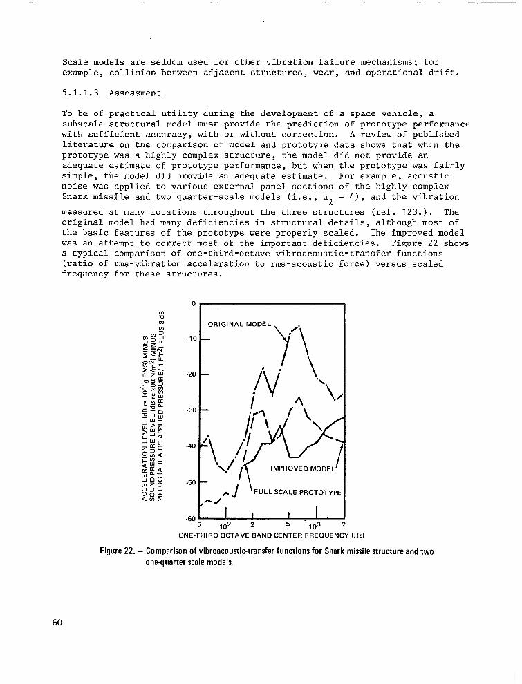
Scale models are seldom used for o t h e r v i b r a t i o n . f a i l u r e mechanisms; f o r example , co l l i s ion be twzen ad jacent s t ruc tures wear, a n d o p e r a t i o n a l d r i f t .
5.1.1.3 Assessment
To be o f p rac t i ca l u t i l i t y du r ing t he deve lopmen t of a space veh ic l e , a s u b s c a l e s t r u c t u r a l modcl must: p rov ide t he p red ic t ion of pro to type per formaxe . with suff ic i -ent accuracy, with or without correc. t ion. A review of published I f - t e r a t u r e on tne comparison of model and prototq-pe daca shows t h a t whc n t h e prototype was a h igh ly complex s t r u c t u r e , t h e model d id no t p rovide an adequate estimate of prototype performance, but when t h e p r o t o t y p e was f a i r l y s i m p l e , t h e model d id p rovide an adequate estimate. For example, acoustic n o i s e was a p p l i e d t o v a r i o u s e x t e r n a l p a n e l s e c t i o n s o f t h e h i g h l y complex Snark missile and two quar te r -sca le models ( i . e . , n = 4 ) , and t he v ib ra t ion
measured a t many loca t ions t h roughou t t he t h ree s t ruc tu res ( r e f . 123 . ) . The o r i g i n a l model had many d e f i c i e n c i e s i n s t r u c t u r a l d e t a i l s , a l t h o u g h most of t h e b a s i c f e a t u r e s of the p ro to type were p rope r ly s ca l ed . The improved model w a s an a t t empt t o c o r r e c t most of the impor tan t def ic ienc ies . F i .gure 22 shows a typical comparison of one-third-octave vibroacous, t ic- t ransfer funct ions ( r a t i o of rms-v ibra t ion acce le ra t ion to rms-acous t ic force) versus sca led f r equency fo r t hese s t ruc tu res .
R
0
- l a
-20
-30
-40
-50
-60
ONE-THIRD OCTAVE BAND CENTER FREQUENCY (HZ)
Figure 22. - Comparison of vibroacoustic-transfer functions for Snark missile structure and two one-quarter scale models.
60

The predict ion produced by o f t e n by more than 20 dB. accuracy, as shown i n t h i s (occas iona l ly i n excess of
t h e o r i g i n a l model was almost always i n e r r o r , The improved model provided some improvement i n t y p i c a l f i g u r e ; b u t t h e e r r o r was s t i l l t o o l a r g e 20 dB and o f t e n in excess of 10 dB) t o p r e c l u d e
i ts p r a c t i c a l u t i l i t y o r t o j u s t i f y i t s cost. Another example of inaccuracies w a s observed between the Apollo boi lerplate service module and i t s one- ten th scale model, shown i n f i g u r e 23 ( r e f . 124) . Great pa ins were t a k e n t o scale n e a r l y a l l s t r u c t u r a l d e t a i l s i n t h e mode l . T ranson ic f l i gh t da t a fo r t he f u l l - s c a l e b o i l e r p l a t e w e r e compared wi th w ind- tunne l da t a fo r t he model. F igure 24 shows a reasonably similar shape between the two normalized random s t r a i n s p e c t r a . U n f o r t u n a t e l y , t h e model underpredic ted the r m s va lue of t h e s t ra in by 8 dB dur ing t he most severe t r anson ic pe r iod . On the o the r hand , t h e model underpredicted the r m s a c c e l e r a t i o n of t h e f l i g h t p r o t o t y p e by only 2 dB. Unfo r tuna te ly , t he model missed the predominant frequency range by a fac tor o f 2 , as shown i n f i g u r e 25. Reasons f o r t h e i n a c c u r a t e p r e d i c t i o n s of the Snark and Apollo models are discussed in references 123 and 124. S i m i l a r r e s u l t s were noted on a Nimbus spacec ra f t a t h ighe r f r equenc ie s ( r e f . 125).
On t h e f a v o r a b l e s i d e i s the comparison of resul ts for s imple panels exposed t o j e t noise , ment ioned prev ious ly in re fe rence 121 . F igure 26 shows t h e e x c e l l e n t p r e d i c t i o n of t h e p r o t o t y p e - s t r a i n s p e c t r a l d e n s i t y from the one - s ix th - sca l e model data . Similar ly , models of s i m p l e s h e l l s ( c y l i n d r i c a l , con ica l , and hemispherical) have shown exce l len t es t imates o f p ro to type na tura l f requencies and mode shapes for lower-order modes. However, no e f f o r t has been made to de te rmine the degree of complexi ty obtainable before pred ic t ion inaccurac ies occur .
5.1.2. Vibration Tests
5.1.2.1 Test C l a s s i f i c a t i o n and Philosophy
Labora tory v ibra t ion tes ts may be ca tegor ized as fo l lows: (a) design develop- ment, (b) q u a l i f i c a t i o n , ( c ) a c c e p t a n c e , and (d) others. Design-development tests a re pe r fo rmed t o p rov ide ce r t a in i n fo rma t ion t o t he des igne r r ega rd ing t h e modal c h a r a c t e r i s t i c s o f t h e s t r u c t u r e ( r e f . 33) , t h e v i b r a t i o n r e s p o n s e to ce r t a in app l i ed l oad ings , t he adequacy of t he des ign , and , i n some cases , the v ibra t ion- fa i lure mechanisms, loca t ions , and l e v e l s . Q u a l i f i c a t i o n tests are performed on f l ight-qual i ty hardware to demonstrate the adequacy of the d e s i g n a n d f a b r i c a t i o n m e t h o d s f o r f l i g h t , u s u a l l y b e f o r e t h e f i r s t f l i g h t . Acceptance tests are performed on ar t ic les i n t e n d e d f o r f l i g h t u s a g e t o demons t r a t e t ha t a predetermined minimum adequacy had been achieved during f a b r i c a t i o n and assembly. Any of t hese may be performed as v i b r a t i o n tests combined wi th o the r l oads and environments. Other tests i n c l u d e ( a ) r e l i a b i l i t y tests, t o d e m o n s t r a t e t h e v a r i a t i o n o f t h e f a i l u r e mechanism between items of hardware under prescr ibed types of l o a d i n g ; ( b ) f r a g i l i t y tes ts , t o map t h e f a i lu re t h re sho ld pe r ime te r unde r a v a r i e t y of loadings or f requencies; and ( c ) c e r t a i n i n t e r i m tests between development and qualification. There i s no common te rminology used th roughout the aerospace f ie ld to descr ibe a p a r t i c u - l a r t y p e of test, so it is n o t uncommon i n two d i f fe ren t vehic le -development programs or in two d i f f e r e n t o r g a n i z a t i o n s t o h a v e two names f o r t h e same type of test.
61

(A) FULL-SCALE FLIGHT ARTICLE
(6) ONE-TENTHSCALE MODEL
Figure 23. - Structural details of the Apollo boilerplate service module.
62

0.01
z a 0.00
a a
a I- v)
w
3 w Y z a
- -10
15
0 200 400 600
FREQUENCY x SCALE FACTOR (Hz)
Figure 24. - Comparison of Apollo boilerplate service module vibration-strain spectra.
0.010
0 a a
ti
z + W A
0 a n 3 4
v) a 2
0.005
I
.w WIND TUNNEL MODEL
1 FLIGHT
200 400 600
FREQUENCY x SCALE FACTOR (Hz)
800
Figure 25. - Comparison of Apollo boilerplate service module vibration-acceleration spectra.
63
I

I MODEL
FULL-SCALE PROTOTYPE
10 2
102 2
. 103
FREQUENCY x SCALE FACTOR (Hz)
Figure 26. - Comparison of vibration-strain spectra for prototype and model panels excited by jet noise.
U s u a l l y , t h e s e l e c t i o n of design-development tests and t h e i r test cond i t ions are a t t h e o p t i o n of the designer and/or program management. Q u a l i f i c a t i o n tests are near ly a lways requi red by c o n t r a c t , w i t h test cond i t ions u sua l ly s p e c i f i e d as somewhat more severe t h a n t h o s e a n t i c i p a t e d f o r f l i g h t . Q u a l i - f i c a t i o n tests are of ten waived when t h e s t r u c t u r e s are t o o l a r g e t o b e t e s t e d . I n t h e s e cases, t h e s t r u c t u r e s are o f t e n " q u a l i f i e d " by v i b r a t i o n analyses and/or tests on c e r t a i n s t r u c t u r a l s e c t i o n s . L a b o r a t o r y v i b r a t i o n - acceptance tests may o r may no t be r equ i r ed by t h e c o n t r a c t . If r equ i r ed , t h e test condi t ions mus t be se lec ted wi th g rea t care, s i n c e t h e t es t degrades the hardware by exposure be fo re f l i gh t , wh i l e t he f l i gh t adequacy i s being demonstrated s imultaneously. Hardware used for tes t ing, o ther than accept- ance t e s t ing , is neve r u sed fo r f l i gh t , excep t unde r unusua l ly spec ia l circumstances.
Labora to ry v ib ra t ion tests are nearly always performed on equipment, sometimes on secondary structure (almost always with equipment items o r dummies), and occas iona l ly on pr imary s t ruc ture .
The s u b j e c t of equipment t e s t i n g w i l l b e l i m i t e d i n t h i s r e p o r t t o t h e d i s c u s s i o n of design and test cr i ter ia . However, i t is l i k e l y i n t h e f u t u r e t h a t some equipment items may serve s imultaneously as minor or major load- ca r ry ing members, so t h a t t h i s d i v i s i o n may eventua l ly d i sappear .
There i s no uniform phi losophy throughout the aerospace industry regarding the t ypes of p r imary o r s econda ry s t ruc tu res t o be t e s t ed . Most s p a c e c r a f t
64

c o n t r a c t s r e q u i r e v i b r a t i o n t e s t i n g o f t h e e n t i r e p a y l o a d . For example, f i g u r e 27 shows the Ranger . spacec ra f t exc i t ed by an e lectrodynamic shaker s i m u l a t i n g t h e l o n g i t u d i n a l v i b r a t i o n a p p l i e d by the l aunch veh ic l e du r ing the l aunch phase o f the miss ion ( re f . 126) ; f igure 28 shows a similar test on t h e Gemini spacecraf t ( re f . 127) . F igure 29 shows the Surveyor spacecraf t exc i t ed by th ree e l ec t rodynamic shake r s s imu la t ing t he v ib ra t ion app l i ed by the t h ree ve rn ie r rocke t eng ines du r ing t he l una r -descen t phase of the miss ion (ref . 128) . The spacec ra f t is inve r t ed t o pe rmi t ope ra t ion of t he r ada r sub - system i n t h e f r e e f i e l d .
Only a few c o n t r a c t s r e q u i r e v i b r a t i o n t e s t i n g of l aunch veh ic l e s o r l a rge spacecraf t because most are too l a rge and t oo heavy t o be t e s t ed conven ien t ly or economica l ly . In some cases, sec t ions o f the l aunch vehic le are t e s t e d ; f i g u r e 30 shows t h e v i b r a t i o n - t e s t s e t u p f o r t h e t h r u s t s t r u c t u r e and a f t s k i r t of t h e S a t u r n S - I 1 s tage ( re f . 129) . E ight hydraul ic shakers exc i ted the s t ruc tu re t h rough a l a r g e f i x t u r e . Dummy engines and equipment, simula- t i ng t he we igh t and cen te r of g r a v i t y o f t h e a c t u a l items, w e r e u s e d t o provide a s imulated loading for the pr imary and secondary s t ructure of t h e sec t ion .
5.1.2.2 T e s t F a c i l i t i e s
There is a wide var ie ty of tes t equipment avai lable for performing laboratory v i b r a t i o n tests. The electrodynamic shaker i s t h e most popular because of t h e ease of c o n t r o l l i n g t h e test. It i s used mostly i n t h e 5- t o 2000-Hz frequency range, a l though the useful upper-frequency l i m i t usual ly depends upon i t s force capaci ty and s ize . Electrodynamic shakers with force-genera- t i n g c a p a c i t i e s up t o 30 000-lb rms are commercial ly avai lable .
Hydraul ic shakers a re used mos t ly in the 0- t o 500-Hz frequency range, a l though the useful upper-frequency l i m i t i s dependent upon the design features of t h e shaker, which vary widely, as w e l l as on i t s fo rce capac i ty and s ize . Hydraul ic shake r s w i th fo rce -gene ra t ing capac i t i e s up t o 250 000-lb rms are commercially a v a i l a b l e .
T e s t systems for providing power and con t ro l t o t hese shake r s a l so va ry w ide ly . For performing s inusoidal v ibrat ion tests, a typ ica l sys t em has an e l ec t ron ic o s c i l l a t o r d r i v i n g an e l e c t r o n i c power amplif ier through a g a i n - c o n t r o l c i r - c u i t , as shown i n f i g u r e 31. The power a m p l i f i e r i n t u r n d r i v e s t h e s h a k e r ( a c t u a l l y a t r a n s l a t i o n a l m o t o r ) which i s a t t a c h e d t o t h e test f i x t u r e and test specimen.
I n n e a r l y a l l tests, a cont ro l acce le rometer i s a t t a c h e d t o t h e test f i x t u r e a t a poin t ad jacent to the mount ing po in t of the spec imen. I f there a re two o r more mounting poin ts , the acce le rometer i s loca ted ad jacen t t o one of them. The acce lerometer s igna l i s e i t h e r f e d d i r e c t l y t o t h e g a i n c o n t r o l c i r c u i t , s o t h a t t h e s h a k e r i s au tomat ic -ga in-cont ro l led (AGC), o r f e d t o a meter, which i s read manual ly , and the gain-control c i rcui t i s then ad jus t ed manually.
65

Figure 27- Laboratory vibration test of the Ranger spacecraft.
66
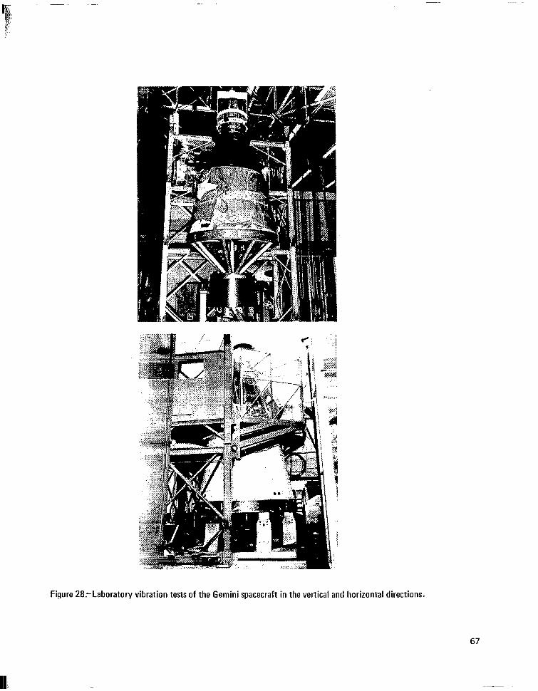
Figure 28.-Laboratory vibration tests of the Gemini spacecraft in the vertical and horizontal directions.

-. . .
Figure 29.-Laboratory vibration test of the Surveyor spacecraft.
68

Figure 30.-Laboratory vibration-test facility of the thrust structure and aft skirt of the S-ll stage, Saturn V launch vehicle.
69

FIXTURE
VAR.FREQ. AMPLIFIER CONTROL GENERATOR- POWER GAIN
ELECTRO- b DYNAMIC
SHAKER
TEST SPECIMEN
J ACCELEROMETER
-
- I 4 AUTOMATIC . PERSONNEL
Figure 31’~Simplified schematic diagram of a typical system for performing sinusoidal-vibration tests.
To perform random-vibration tests, a typ ica l sys t em con ta ins a random-noise gene ra to r d r iv ing an e l ec t ron ic power ampl i f i e r t h rough a spec t rum equal izer , which c o n s i s t s o f a l a r g e number (usua l ly 40 o r 80) of contiguous bandpass f i l t e r s , as shown i n f i g u r e 32. Each f i l t e r c o v e r s a narrow band portion of the spectrum (usual ly 50 o r 25 Hz). The ga in of e a c h f i l t e r is v a r i e d a u t o - m a t i c a l l y by means of AGC, or manual ly . The ou tpu t s igna l s f rom a l l t h e f i l t e r s are summed a n d f e d t o t h e power a m p l i f i e r , w h i c h i n t u r n d r i v e s t h e shaker , f ixture , and specimen. The cont ro l acce le rometer i s a t t a c h e d t o t h e f i x t u r e a t a poin t ad jacent to the spec imen, as descr ibed prev ious ly . The acce le romete r s igna l i s f e d t o a spec t rum ana lyzer , which cons is t s of a set of f i l t e r s t h a t h a v e b a n d p a s s f r e q u e n c i e s i d e n t i c a l t o t h o s e i n t h e s p e c t r u m e q u a l i z e r . The s i g n a l from each f i l t e r i n t h e a n a l y z e r i s e i t h e r f e d t o i t s r e s p e c t i v e e q u a l i z e r c i r c u i t , c o n t r o l l i n g t h e e q u a l i z e r g a i n by AGC, o r f e d t o a meter (one of 40 o r 80), which i s read manually. The ga in of a l l e q u a l i z e r c i r c u i t s is adjusted manually. These systems are obviously expen- sive. It must b e n o t e d t h a t f i g u r e s 31 and 32 show on ly t he c r i t i c a l “b lack boxes” of t h e test equipment. In a c t u a l i t y , t h e r e are many a d d i t i o n a l items of equipment needed f o r c o n t r o l and overload protect ion.
5 .1 .2 .3 Qual i f icat ion-Test Requirements and Their Select ion
Because of i t s c o n t r a c t u a l s t a t u s , t h e q u a l i f i c a t i o n test i s probably the most important type of vibrat ion test performed during vehicle development . The i n t e n t o f most q u a l i f i c a t i o n tests i s to accep t f l i gh t - adequa te ha rdware
70

ACCELEROMETER \
BANDPASS FILTER 1 CONTROL 1
I I . BANDPASS GAIN POWER FILTER 2
ELECTRO-
NOISE GENERATOR
-b - CONTROL2
b SUMMER + b DYNAMIC - + AMPLIFIER SHAKER
4 1
L
BANDPASS FILTER N CONTROL N
N = 4 0 O R 8 0
I
b-- SPECTRUM ANALYZER
I AUTOMATIC
L
- - ~
BANDPASS FILTER 2
TEST PERSONNEL
BANDPASS FILTER N
N = 4 0 O R 8 0
Figure 32:Simplified schematic diagram of a typical system for performing random vibration tests.

and t o reject f l i g h t - i n a d e q u a t e h a r d w a r e . S h o r t o f a c t u a l f l i g h t test, i t i s i m p o s s i b l e t o a c h i e v e t h i s g o a l i n p r a c t i c e . T h u s , i t is n e c e s s a r y t o c o n s i d e r the t radeoffs be tween under tes t ing and over tes t ing . Obvious ly , i t i s e a s y t o avoid near ly a l l u n d e r t e s t i n g by i n c r e a s i n g test levels u n t i l o n l y t h e most rugged hardware surv ives . In th i s case, much o f t he ha rdware t ha t i s r e a l l y adequate for f l igh t mus t be redes igned and re tes ted , o f ten caus ing unnecessary weight increases and cost and schedule s l ippage. Many test s p e c i f i c a t i o n s are w r i t t e n by personnel whose main assignment i s t o e n s u r e h i g h r e l i a b i l i t y and s t r u c t u r a l i n t e g r i t y , l e a v i n g t o program management and o ther g roups the weight , c o s t , and schedule problems result ing from overly conservative tes t levels ( r e f . 130). With t h i s i n f o r m a t i o n , i t i s n o t s u r p r i s i n g t o f i n d t h a t t h e r e are many instances where program management has dec ided t o f l y space veh ic l e s w i th ha rdware t ha t has f a i l ed v ib ra t ion -qua l i f i ca t ion tests.
The v ib ra t ion p rob lem tha t has p robab ly been d i scussed i n t he ae rospace i n d u s t r y more than any o ther over the years is t h a t o f t h e s e l e c t i o n of q u a l i - f i c a t i o n tes t levels and dura t ions . The f a c t o r s t h a t s h o u l d b e c o n s i d e r e d i n t h i s s e l e c t i o n i n c l u d e :
a The degree of s i m i l a r i t y between the tes t and t h e f l i g h t conf igura t ion .
a The c h a r a c t e r i s t i c s o f t h e test f a c i l i t y .
a The method of c o n t r o l l i n g t h e tes t .
a The d e g r e e o f c o n f i d e n c e i n t h e f l i g h t v i b r a t i o n p r e d i c t i o n s .
a The number of test spec imens t o be u sed i n t he q u a l i f i c a t i o n of each hardware i t e m .
a The economic balance between the cost of p o s s i b l e f l i g h t f a i l u r e s a n d t h e c o s t of p o s s i b l e t es t f a i l u r e s .
The degree of s imi l a r i t y be tween test and f l i g h t c o n f i g u r a t i o n s w i l l have a ma jo r i n f luence on t he l owes t f r equency fo r wh ich va l id t e s t ing can be pe r - formed. Often, t h i s f r equency l i m i t can be readi ly determined by comparing t h e modal c h a r a c t e r i s t i c s a t the lower resonance of t h e test specimen with t h e modal c h a r a c t e r i s t i c s e x p e c t e d f o r t h e f l i g h t c o n f i g u r a t i o n . I f t h e s e occur a t s i g n i f i c a n t l y d i f f e r e n t f r e q u e n c i e s , o r i f no similar mode shapes e x i s t , no v a l i d v i b r a t i o n t e s t i n g i s p o s s i b l e f o r t h e s e modes ( r e f . 131) . For t h i s r e a s o n , i t i s common p r a c t i c e t o test a s p a c e c r a f t by c c n o t c h i n g y y t h e v i b r a t i o n tes t leve l i n t h e v i c i n i t y of i t s fundamental resonance.
Ac tua l ly , an i den t i ca l na tu ra l f r equency o r mode shape could exis t only by coincidence because of t he d i f f e ren t mechan ica l impedance cha rac t e r i s t i c s between the test f i x t u r e and t h e f l i g h t s t r u c t u r e a d j o i n i n g t h e h a r d w a r e sec t ion under cons idera t ion . It is poss ib le , however , to force the spec imen t o h i g h l e v e l s a t f r equenc ie s co r re spond ing t o t he f l i gh t - r e sonan t f r equenc ie s
72

a n d “ n o t c h y y t h e l e v e l s a t f requencies cor responding to the t es t - resonant f r equenc ie s and f l i g h t - a n t i r e s o n a n t f r e q u e n c i e s , i f t h e s h a k e r c a p a c i t y i s l a r g e enough and i f t h e r e s o n a n t c h a r a c t e r i s t i c s o f t h e f l i g h t c o n f i g u r a t i o n (usua l ly no t ye t f lown) are known wi th su f f i c i en t accu racy i n t he f r equency r a n g e o f i n t e r e s t . However, t h i s i s almost never done.
For se l le r s t r u c t u r e s , s u c h as t h e s p a c e c r a f t shown i n f i g u r e 2 7 , i t i s common p r a c t i c e t o v i b r a t e t h e s p e c i m e n by a s ing le shake r t h rough a test f ix ture . There are u s u a l l y g r e a t p a i n s t a k e n t o r e s t r a i n t h e v i b r a t i o n m o t i o n o f t he shake r and f i x tu re t o a s i n g l e d i r e c t i o n , and t o make t h e test f i x t u r e as r i g i d and as massive as t h e f o r c e l i m i t a t i o n s of the shaker permi t . Such care he lps avo id any con t r ibu t ion t o t he r e sonan t behav io r of the specimen by t h e f i x t u r e , e x c e p t a t h igher f requencies . This is t o b e compared with t h e f l i g h t c o n f i g u r a t i o n w h e r e t h e a d j o i n i n g s t r u c t u r e i s p a r t of t he r e sonan t behavior , o f ten a l lowing mot ion in a l l Et-ree or thogonal (autual ly perpendicu- l a r ) d i r ec t ions . Th i s pe rmi t s mu l t id i r ec t iona l r e sonance , and , i n t h e case of most hardware t h a t i s a t t ached t o ad jo in ing structure through two o r mor? p o i n t s of a t cachnen t , a l l ows va r i a t ion of amplitude and phase between attach- ment points throughout the frequency range. Thus, there i s a cons iderable l ack of s imula t ion 5 us ing s ing le - shake r r e s t r a ined -mot ion v ib ra t ion , t e s t ing w i t h r i g i d f i x t u r e s . Much of t h i s prcblem can be reduced by us ing par t o f the f l i gh t s t ruc tu re ad jo inFng che tes t sp,scimen 2s a p o r t i o n of t h e tes t f i x t u r e .
The var ia t ion be tween a t tachment po in ts can o f ten be improved by mul t ip l e s h a k e r s w d e r s e p a r a t e c o n t r o l , b u t t h i s i n c r e a s e s t h e c o s t of tesc i r lg . In add i t ion , t he shake r app l i e s t he v ib ra t ion fo rce i n on ly one d i r ec t ion , whereas t h e f l i g h t e x c i t a t i o n i s a p p l i e d i n t h e t h r e e o r t h o g o n a l d i r e c t i o m s i r n u l - taneously. Usual ly , i t i s assumed t h a t v i b r a t i o n a p p l i e d s e q u e n t i a l l y i n e a c h of t h r e e o r t h o g o n a l d i r e c r i o n s f o r a s p e c i f i e d t ixe dura t ion pe r d i r ec t ion has t h e same tianage p o t e n z i a l as v i b r a t i o n a p p l i e d i n a l ; t h r e e d i r e c t i o n s s i m u l - tanecjusly f o r t h e same dura t ion . However, this assumption can only be v a l i d fo r r e sonan t behav io r i n one d i r ec t ion and by co inc idence fo r mu l t id i r ec t io r l a l resonance.
As s t a t e d p r e v i o u s l y , most v i b r a t i o n tests a re con t ro l l ed f rom a s i g n a l generated by the control accelerometer , which i s a t t a c h e d t o t h e test fixtu:-e ad jacen t t o t h e ruountillg p o i n t o r t o c n e of t he noun t ing po in t s . I n t he l a rge major i ty of t es t s , t h e s p e c i m e n i n t e r f a c e s w i t h t h e f i x t u r e a t s e v e r a l p o i n t s o r a l o n g l i n e s o r s u r f a c e s . M u l t i d i r e c t i o n a l r e s o n a n t b e h a v i o r of t t e test spec. imen ( including rotat ion) , which is coup led w i th f i x tu re and shaker resonarlces a t the h igher f requencies , usua l ly cames the v ibra t ion ampl i tud .2 to va ry be tween moun t ing po in t s o r a long t he i n t e r f ace . S ince t he con t ro l scceierometer senses moti .on a t only one o f these po in ts , under tes t ing o r ove r t e s t ing u sua l ly occu r s a t the other mounting points, the magnitude of which depends on t h e mode shapes o f the mul t id i rec t iona l resonances . To avoid t h i s u n d e r t e s t i n g o r o v e r t e s t i n g d u r i n g a s inusoida l v ibra t jon . t es t . , s . evera1 cont ro l acce le rometers (usua l ly f rom t h r e e to s ix) can be used and. t h e i r s igna l s mon i to red s imul t aneous ly t o select the lowes t o r h ighes t ampl i tude f o r test c o n t r o l . S p e c i a l test equipment i s commerc ia l ly ava i lzb le for irnp1.e- men t ing t h i s s e l ec t ion au tomat i ca l ly .
73

Another technique employs the averaging of the. s i g n a l s f r o m t h e several acce lerometers . S igna l averaging may b e u s e d f o r s i n e o r random v i b r a t i o n t e s t i n g . S i g n a l a v e r a g i n g may be performed i n one of two ways: (1) i n s t a n - taneous averaging and (2) t i m e d i v i s i o n m u l t i p l e x i n g (TDM). Overtest ing can occur wi th the ins tan taneous averaging technique i n any mode when two of the.
cont ro l acce le rometers are mounted a t l o c a t i o n s t h a t are v i b r a t i n g 180 o u t of phase. This problem is e s p e c i a l l y a c u t e when only two accele.rometers are u s e d , o r when the ou t -of -phase acce le rometers are v i b r a t i n g a t high ampli tude relative to the o ther acce le rometers . This p roblem may be avoided by using TDM, which samples the acce le rometer s igna ls in sequence to form a composite s igna l which i s then u sed fo r manual or aut-omst ic tes t c o n t r o l . However, TDM i s not without problems, such as the s e l . ec t ion o f samp1.e time d u r a t i o n s from one signal. t o t h e n e x t , a l t h o u g h t h e s e e f f e c t s c a n b e m i n i m i z e d ( r e f . 132). Special equipment i s commercial ly avai lable for implementing tes t c o n t r o l w i t h TDM.
0
A s seen from the t i m e h i s t o r i e s and t h e c h a n g e s i n t h e v i b r a t i . o n s p e c t r a i l l . u s t r a t e d i n f ? g u r e 1 , t h e f l i g h t v i b r a t i o n i s n o n s t a t i o n a r y , e s p e c i a l l y for the per iod f rom I . i f to f f th rough q . However, most p r e s e n t l y a v a i l a b l e max v i b r a t i o n test systems are c a p a b l e o f c o n t r o l l i n g s t a t i o n a r y tests on1.y. T h u s , s t a t i o n a r y t e s t i n , % i s employed f o r n o n s t a t i o n a r y f l i g h t c o n d i t i o n s . Severa l test techniques may be u sed , bu t a l l . pe rmi t ove r t e s t ing i n t he t i m e and/or frequency domain.’ The most popular i s the use of a v ib ra t ion spec t rum w h i c h e n v e l o p e s t h e v i b r a t i o n s p e c t r a f o r t h e v a r i o u s p r e l a u n c h a n d m i s s i o n e v e n t s t h a t e x h i b i t h i g h v i b r a t i o n ( a c c e p t a n c e v i b r a t i o n t e s t i n g , s t a t i c f i r i n g , l i f +of f , t ransonic , s tage-powered f l igh t for hardware near
e n g i n e s , e t c . ) . O f t e n t h e t i m e d u r a t i o n f o r t h i s s t a t i o n a r y l a b o r a t o r y test is s e l e c t e d t o b e t h e sum of t h e c c e f f e c t i v e ” d u r a t i o n s of these prel-aunch and miss ion events . Thus , cons iderable over tes t ing may r e s u l t compared t o f l igh t condi t ions . Over tes t ing can somet imes be minimized when q u a l i f i c a t i o n t e s t i n g is performed by using several tests in s equence , each t.est r e p r e s e n t - i n g a d i f f e ren t phase o f t he mi s s ion o r o f p re l aunch cond i t ion , and havin.g a d i f fe ren t v ibra . t ion spec t rum. However, t h i s series of tes t se tups , checkou t s , e t c . . , may be t ed ious to per form. In the fu ture , spec ia l equipment o r t ech- niques w i l l p r o b a b l y b e a v a i l a b l e t o p e r m i t n o n s t a t i o n a r y v i b r a t i o n t e s t i n g . Two seem most l i k e l y : ( 1 ) t h e u s e of a nons ta t iona ry s igna l , which has been prerecorded on to ma-gnet ic t ape tha t i s fed c l i rect ly t o t h e ki.nd of e l e c t r o n i c power a m p l i f i e r shown i n f i g l l r e 32 (using no AGC), a f t e r t he sys t em has been ca l ibra ted mznual ly wi th a low-level white random spectrum; and (2) the use of an e l e c t r o n i c programmer between the cont ro l acce le rometer and AGC ( f ig . 32 ) .
%ax
The degree o f con f idence i n t he f l i gh t -v ib ra t ion p red ic t ion shou ld a l so i n f l u e n c e t h e s e l e c t i o n o f t h e q u a l i f i c a t i o n t e s t levels and dura t ions . Classical techniques of v ihra t . io r? p red ic t ion appl - ied to a s o p h i s t i c a t e d r ep resen ta t ion o f t he f l j . gh t s t ruc tu re and test specimen, discussed .in Sect ion 4 .1 , should permit a r a t . h e r a c c u r a t e s e l e c t i o n of tes t levels up t o a f requency where the representa t ion becomes i n c r e a s i n g l y less a c c u r a t e . A t h igher f req l lenc ies the test levels mus t he i nc reased , u sua l ly i n some a r b i - t r a r y manner to avo id t . he poss ib i l i t y o f unde r t e s t ing . S imi l a r ly , t he
74

s t a t i s t i c a l - e n e r g y a n a l y s i s (SFA), d i s c u s s e d i n S e c t i o n 4.2, may be used for s e l e c t i n g q u a l i f i c a t i o n - t e s t levels at hi.gher frequencies. However, sin.ce SEA i s less p rec i se a t h igh f r equenc ie s t han c . l a s s i ca1 . t echn iques are at low f r e q u e n c i e s , t h e test l e v e l s d e r i v e d by SEA must be somewhat i n c r e a s e d t o avoid under tes t ing . The amount of t h e i n c r e a s e w i l l a l s o depend upon t h e degree of: s o p h i s t i c a t i o n u s e d i n t h e s t r u c t u r a l r e p r e s e n t a t i o n . If s u f f i c i e n t d e t a i l is inc luded , t he test level should no t be more t h a n t h e SEA upper bound descr ibed prev ious ly , which wa.s e s t a b l i s h e d hv s e t t i n g t h e s t r u c t u r a l damping to ze ro and u t i l i z ing on ly t he coup l ing loss f a c t o r .
Extrapolation teGhniques (Sec. 4.3) are most o f t e n u s e d f o r test level selec- t i o n . The degree of c o n f i d e n c e i n t h e p r e d i c t i o n w i l l depend upon t h e s i m i l a r i t y between t h e r e f e r e n c e a n d t h e new v e h i c l e , and how t h e r e f e r e n c e v e h i c l e d a t a were grouped, and i f a p p l i c a b l e , s t a t i s t i c a l l y a n a l y z e d . I f t h e r e f e r e n c e and new v e h i c l e s t r u c t u r e s are q u i t e similar, i t might be assumed t h a t t h e v i b r a t i o n p r e d i c t i o n would be qu i te accura te . However, as discussed previously in Sect ion 4 .3 .2 on scal ing methods, Condos and Butler found cons iderable d i f fe rences . be tween v ibra t ion pred ic t ions and subsequent measurements on a ne.w vehic:.e, even when exce l l en t s imi l a r i t y ex i s t ed be tween t h e r e f e r e n c e and t h e new veh ic l e , and t he r e f e rence veh ic l e da t a w e r e grouped t n t o z o n e s f o r s i m i l a r l o c a t i o n and type of s t r u c t u r e . From t h i s , a s w e l l as from similar experience on the uprnted Sat lwn I launch vehic le , increased tes t l e v e l s t o a v o i d t h e p o s s i b i l i t y of unde r t e s t ing seem i n o r d e r .
It would appea r t ha t a g r e a t e r i n c r e a s e would be i n o rde r fo r f r equency- response methods (Sec. 4 .3 .1 ) , s ince even l e s s s imi l a r i t y be tween veh ic l e s is general ly found. Howe.ver, i n a l l e x t r a p o l a t i o n methods , t h e number of measurements , the grouping of the data , and the type of s ta t i s t ica l a n a l y s i s ( i f u s e d ) o f t c n h a s a large in f luence on t h e v i b r a t i o n Level p red ic t ed and thus on t h e r e s u l t i n g tes t l e v e l . I n r e g a r d t o t h e nurnber of measurements, for example, Stevens compared eight vibrat ion measurements made on Apollo-service-module external panels (considered s i m p l e ae rospace s t ruc tu re ) w i t h t h e t o t a l p o p u l a t i o n of 180 measurements made on t h e s e p a n e l s i n t h e radial d i r e c t i o n when t h e s e r v i c e module w a s acous t i ca l ly t e s t ed ( r e f . 133) . These eight measurements were se1ecte .d because their locat ions corresponded with f l ight-measurement locat ions. Figure 33 shows t h a t g e n e r a l l y t h e r e was a 3-dB difference between random v i b r a t i o n s p e c t r a l e n v e l o p e s f o r t h e s m a l l and l a r g e number of measurements. This comparison has a d i r e c t b e a r i n g on t h e s e l e c t i o n of test l e v e l s when only a smal l number of measurements are used f o r a zone of t h e r e f e r e n c e v e h i c l e in a p a r t i c u l a r d i r e c t i o n .
In rega.rd to data grouping, care i s u s u a l l y r e q u i r e d ( r e f . 86). For example, f o r s t a t i s t i c a l a n a l y s i s , i t i s common p r a c t i c e t o p u t a l l vibrat ion measure- ments f o r a p a r t i c u l a r zone of t h e r e f e r e n c e v e h i c l e i n t o t h e same group, independent of t h e d i r e c t i o n of t h e measurement. For s t r u c t u r e e x h i b i t i n g v ib ra t ion p redominan t ly i n one d . i r ec t ion , t h i s t ype of data grouping can produce two e f f e c t s on t h e test ].eve]. F i r s t , o v e r t e s t i n g c a n o c c u r i n t h e two d i r e c t i o n s of lower v ibra t ion when t h e test l e v e l i s s e l e c t e d on t h e b a s i s o f t he en t i r e popu la t ion of three directional measurements. Second, over- t e s t i n g can even occur i n t h e d i r e c t i o n of h i g h e s t v i b r a t i o n i f t h e test. .levels are s e l e c t e d on the bas i s o f a s t a t i s t i c a l a n a l y s i s which uses the
75
I

180 MEASUREMENTS, -."-a","""-~
2 10
5 1 02
2 5 103
FREQUENCY (Hz)
Figure 33.-Comparison of spectral envelope for 8 and 180 vibration measurements made on the external panels of the Apollo service module during acoustic testing.
mean va lue and s t anda rd dev ia t ion of t h e e n t i r e d a t a p o p u l a t i o n . A few data p o i n t s f o r t h e two d i r e c t i o n s of lower vibrat ion can cause a s i g n i f i c a n t i n c r e a s e i n t h e s t a n d a r d d e v i a t i o n w i t h o u t a n e q u i v a l e n t d e c r e a s e i n t h e mean value. Thus, i f t h e test l e v e l was based on a c e r t a i n h i g h p r o b a b i l i t y level, such as t h e 95 p e r c e n t i l e , a higher test l e v e l would be produced by using a l l measurements ( independent of direction) than would b e produced by us ing on ly measurements f o r t h e d i r e c t i o n of h i g h e s t v i b r a t i o n .
Although not of ten considered, the number of test spec imens used for qua l i f i - c a t i o n t e s t i n g s h o u l d i n f l u e n c e t h e s e l e c t i o n of t h e tes t level. Of p a r t i c u l a r concern i s t h e v a r i a t i o n of t h e f r a g i l i t y l e v e l from specimen t o specimen. For tuna te ly , t he p r imary f a i lu re mechanism of primary and secondary s t ruc tu re i s fa t igue caused by response a t the lower resonant f requencies . The f r a g i l i t y ( t i m e - t o - f a i l u r e ) v a r i a t i o n i s of ten acceptab le here because manufac tur ing to le rances can be reasonably cont ro l led . The oppos i t e i s sometimes observed f o r equipment items, s ince t he p redominan t f r ag i l i t y r ange can occu r a t t h e higher f requencies where manufactur ing var ia t ions cannot be adequately cont ro l led . This i s because t o l e rances a r e u sua l ly con t ro l l ed t o mils ( i . e . , m i l l i - i nches ) , whereas r e l a t ive v ib ra t ion d i sp l acemen t s o f t en occu r i n t he micro-inch range, and a l so occu r where o t h e r f a i l u r e mechanisms than fatigue, such as th re sho ld c ros s ings , may be dominant. When tes t specimens are
76


2
5
2
10-2
5
2
10-3 10
2 102 103
FREQUENCY (Hz)
Figure 34,Predicted vibration spectrum and a five-segment spectral envelope.
antiresonance (refs. 136 and 137). Thus, tolerances are usually specified for the test spectrum, often in the vicinity of +3 dB for narrow-band analysis. If it is desired to avoid any possibility of undertesting, the test spectrum must be increased to match the lower tolerance. Then additional overtesting is produced at other frequencies. However, there has been much discussion regarding the necessity for this increase, since many test failures, as well as flight failures, are likely to occur at frequencies corresponding to antiresonances, as measured by an accelerometer on the test fixture or at the flight interface, although these antiresonances would not occur at identical frequencies (refs. 138 and 139).
Many of these problems may be avoided by using a test method developed by Curtis (refs. 140 and 141), sometimes called “random on random”. Three high-level random vibration narrow-band ccspikesyy are applied simultaneously with a lower-level wideband random vibration spectrum, as shown in figure 35. Curtis suggests that (a) the levels for the wideband and narrowband portions be determined from the mean and 98% values, respzctively, which are calculated from equation (15) in Section 4.3.1; (b) 12.5% bandwidths be used for the three narrow-band spectra; and (c) the “spikesyy be stepped sequentially over a given frequency range (fig. 35), but never overlap. Of course, other variations are possible.
Undertesting can result when a possible failure is dependent upon simultaneous high-level excitation at two or more frequencies, which might occur in flight but is not programmed into the narrow-band sequence. Overtesting and/or
78

r- I I I 1 I I I I I
r
I
r- "-I
I I I I I I I I
1
"1 L" I I I I I I I 1 I I
I -1 I I I I 1 I I
. . . .- . . ~~ ~
FREQUENCY
Figure 35. - Random vibration-test spectrum consisting of high-level narrow band "spikes" superimposed on lower-level wideband spectrum.
under tes t ing can a l so occur , depending upon t h e t i m e du ra t ion of app l i ca t ion of each narrow-band combination, as well as the wideband spectrum. However, C u r t i s r e p o r t s good co r re l a t ion be tween f l i gh t and l abo ra to ry r e su l t s fo r equipment used i n a i r c r a f t .
5 .1 .2 .4 A l t e rna t ives fo r In su f f i c i en t -Force Capac i ty
I f t h e test l e v e l i s too h igh o r t he t es t specimen too heavy, the shaker 's fo rce capac i ty may be exceeded. The obvious solut ion i s t o u s e a l a r g e r shaker o r mul t ip le shakers . But i n many cases , the l a rges t commerc ia l ly ava i l ab le shake r i s a l ready cons idered ( for the f requency range des i red) o r s p a t i a l l i m i t a t i o n s p r e c l u d e t h e u s e of a s u f f i c i e n t number of shakers . In t h e s e c a s e s , a l t e r n a t e m e a s u r e s a r e r e q u i r e d . F i r s t , t h e C u r t i s method should be cons ide red , s ince a much lower rms a c c e l e r a t i o n i s r equ i r ed , compared t o tha t for the overa l l enve lope of the h igh- leve l nar row-band Second, consideration should b e given to using high-level narrow-band random vibra t ion which i s appl ied s imul taneous ly a t the p redominant resonant f r equenc ie s o f t he test specimen f o r t h e d e s i r e d t i m e du ra t ion , w i th t he su r - p lus shaker capac i ty ( i f any) be ing used to p roduce a lower - l eve l wideband random spec t rum outs ide the resonant f requency ranges . A l ow- leve l s inuso ida l resonance search may be u sed t o e s t ab l i sh t he p redominan t r e sonan t f r equenc ie s . Thi rd , a narrow-band random spectrum swept across the frequency range may be used, as described by Booth and Broch (ref. 142) . F i n a l l y , a s inusoid may be used fo r r e sonan t dwe l l a t the va r ious r e sonan t f r equenc ie s , o r i t may be swept across the f requency range. Some type of sine-random equivalence i s
79

"
usually assumed (e.g., ref. 66), although it is unlikely that it can be achieved (ref. 1 4 3 ) . Of these substitutes, the Curtis method is probably the most realistic; the random-at-resonance method, the most conservative; and swept random, swept sine, and sine dwell, the lowest in cost.
A completely different technique is to specify and control force, rather than control acceleration in vibration testing. Although this form of testing is harder to implement, and vibration force measurements are not normally made in flight, it is possible that much more realism may be achieved with force- control testing, thus avoiding undertesting and overtesting. Otts and his associates have demonstrated that random-force vibration testing can be implemented practically in the laboratory (refs. 144 and 1 4 5 ) .
5.1.2.5 Acceptance-Test Requirements and Their Selection
Acceptance testing of articles to be used later for flight is seldom performed on structure, but is often performed on equipment items. Variations in structural integrity are usually small for structures, especially in the lower-order modes, so that qualification testing of an earlier specimen at higher levels (to avoid the possibility of undertesting), plus normal inspec- tion of the flight-usage structure, should assure the adequacy of the structure for flight. On the other hand, there can be large variations in the structural integrity and operational performance of equipment, usually because the predominant response is in the higher-order modes. Thus, quali- fication testing at higher levels, plus normal inspection, will not necessarily assure flight adequacy. A s stated previously, the test levels and durations must be selected with great care so that degradation resulting from preflight exposure is minimized while flight adequacy is being demonstrated.
Most of the problems found in the selection of qualification-test levels are also encountered in the selection of acceptance-test levels. However, the "solutionsJy to these problems are usually different. For qualification, a series of test inadequacies are usually countered by a series of test-level increases (i.e., overtesting), whereas for acceptance, the test inadequacies are usually judged equally for their effects on undertesting and overtesting. It should be remembered that the cost of an acceptance-test failure is almost always much less than the cost of a flight failure. It is not un- common to find acceptance-test levels and durations specified as a certain percentage of qualification-test levels and durations. In some cases, stage static-firing tests (i.e., preflight acceptance firings of rocket engines in their stages) are used in lieu of laboratory acceptance tests. This is usually justified by assuming that there are fairly minor differences between flight and static-firing vibration levels, but this assumption is often violated. For example, for certain sections of the upper stage of a launch vehicle, the acoustic noise and the resulting equipment vibration from the upper-stage rocket engine(s) during static firing may be much less than the noise and vibration from the first-stage rocket engine(s) during liftoff.
Consideration must be given additionally to the differences in the cost between laboratory acceptance-test failures and static-firing failures. It is thus easy to see why acceptance tests are not always used and why there is no uniformity in acceptance-test level selection.
80

5.1.2.6 Design-Development T e s t Se l ec t ion
There i s a tremendous v a r i e t y of design-development tests (DDT), s i n c e t h e major goal of these tests i s u s u a l l y t o p r o v i d e i n f o r m a t i o n t o t h e d e s i g n e r and program management on the. adequacy of the des ign and on t h e v i b r a t i o n c h a r a c t e r i s t i c s of the hardware , in case the des ign is inadequate. These tests are usua l ly per formed qu i te ear ly in the vehic le deve lopment s o t h a t program schedules are n o t a f f e c t e d i f d e s i g n c h a n g e s are considered necessary. The t e s t - t o - f a i l u r e t e c h n i q u e i s of ten used during design development to e s t a b l i s h m a r g i n s o v e r f l i g h t a n d q u a l i f i c a t i o n - t e s t c o n d i t i o n s . S i n c e t h e y are performed to acqu i r e des ign i n fo rma t ion , t he re i s no stigma a t t a c h e d t o a DDT f a i l u r e . It is n o t uncommon t o f i n d t h a t t h e f i r s t items o f f t h e p r o d u c t i o n l i n e are u s e d f o r v i b r a t i o n DDT, s ince t hey o f t en con ta in minor f l aws , pa t ches , etc. , which make them u n s u i t a b l e f o r - o t h e r u s e s , but they are o f t e n s t i l l a d e q u a t e f o r DDT purposes. Program management should consider DDT as a n i n e x p e n s i v e t o o l i n a v o i d i n g c o s t l y f a i l u r e s l a te r i n t h e program.
5.1.2.7 Assessment
It can be concluded from the preceding t h a t i t is impossible to perform a v i b r a t i o n test which, even under the best circumstances, avoids both over- t e s t i n g and under tes t ing . Never the less , i t i s v i t a l l y i m p o r t a n t t o any v e h i c l e - d e v e l o p m e n t p r o g r a m t h a t , d e s p i t e t h i s f a c t , t h e most r e a l i s t i c test condi t ions avai lable under the c i rcumstances be sought , and the best t radeoff of f a c t o r s i n f l u e n c i n g t h e d e g r e e of unde r t e s t ing o r ove r t e s t ing be s e l e c t e d . Arbi t ra ry dec is ions concern ing test t e c h n i q u e s , l e v e l s , and durat ions can cause a considerable and sometj.mes an enormous unnecessary expense to the program i n terms of r e l i a b i l i t y , s c h e d u l e , and cos t . For these reasons , l i t t l e r e l i ance shou ld be p l aced on gene ra l spec i f i ca t ions ( r e f . 146) pu rpor t ed t o be app l i cab le t o eve ry space veh ic l e .
5 .1 .3 Acoust ic Tests
I n t h e p a s t , l a b o r a t o r y a c o u s t i c tests were used on an occas iona l bas i s t o s u p p l e m e n t q u a l i f i c a t i o n v i b r a t i o n t e s t i n g of equipment. However, s i n c e two of the major causes of s t r u c t u r a l v i b r a t i o n are a c o u s t i c n o i s e at l i f t o f f and aerodynamic noise during the t ransonic and q r e g i m e s , i t was a n a t u r a l
development t o cons ide r acous t i c no i se as a labora tory source o f space-vehic le v i b r a t i o n . The Titan program was t h e f i r s t t o u t i l i z e a c o u s t i c t e s t i n g f o r the design development of v e h i c l e s t r u c t u r e s u b j e c t e d t o a c o u s t i c n o i s e ( r e f . 147) . More r e c e n t l y , a c o u s t i c t e s t i n g was used on the Apollo program (a) f o r q u a l i f i c a t i o n of equipment i n l i e u of q u a l i f i c a t i o n v i b r a t i o n t e s t i n g , ( b ) f o r q u a l i f i c a t i o n o f s t r u c t u r e , and (c ) for rev is ion of v i b r a t i o n d e s i g n and tes t requirements ( refs . 148 through 152) . Since the major object ive of a c o u s t i c tests is t o p r o d u c e v i b r a t i o n i n a l a r g e test specimen, i t is common t o c a l l them v ib roacous t i c tests.
max
5.1.3.1 T e s t Faci l i t ies
The f a c i l i t i e s u s e d f o r t h e s e tests are many and va r i ed . For example, f i g u r e 36 shows t h e OGO s p a c e c r a f t on t h e f l a t b e d of a t r u c k l o c a t e d i n a n
81

r-
Figure 36.-Acoustic test of the O G O spacecraft near the discharge nozzle of a large blowdown wind tunnel.
open f i e l d n e a r t h e d i s c h a r g e n o z z l e of a l a r g e blowdown wind tunne l ( r e f . 153) . Here, t h e a c o u s t i c l eve l and s p e c t r a are dependent upon (a) t h e mass and v e l o c i t y of the d i scharge f low, (b) the d i s tance f rom the nozz le ex i t to the test specimen, (c) the angle between the exhaust d i rect ion and an imaginary l i ne connec t ing t he nozz le ex i t w i th t he spec imen , and (d) climatic condi t ions .
A similar arrangement may also be used with a rocke t engine as t h e n o i s e source. However, i f t h e a c o u s t i c tes t i s i n t e n d e d t o b e performed as a ' ( f r e e r i d e ' ) on a wind-tunnel or rocket-engine t e s t , a g rea t d i sc repancy may e x i s t be tween the des i red and the ac tua l test d u r a t i o n . I n f i g u r e 3 7 , t h e S - I 1 s t a g e of the Sa turn V launch vehic le i s shown dur ing i t s i n s t a l l a t i o n i n a l a rge r eve rbe ran t tes t f a c i l i t y ( r e f . 154) . The p rogres s ive test f a c i l i t y used f o r t h e a c o u s t i c tests of the Apollo lunar module and the carmr:acld and service modules i s shown i n f i g u r e 38 ( re fs . 150 , 155 , arid 156) . In t he l a t t e r c a s e , t h e e x t e r n a l . s t r u c t u r e i s exc i t ed by ncousti t : noise which i s propagated down 15 ducts , each duct having i t s cwn noise source . The 16 sources may be operated and coztrol led tc jgather , independent ly , or in any combinat ion. These noise sousces, and those used in the previous.ly mentioned S - I 1 tests , a r e air modulators. These devices work on t h e p r i n c i p l e of e:rhausting high-pressuse a i r through an o r i f ice whose c r o s s - s e c t i o n a l a r e 2 i s modul.ated by a n e l e c t r o - magnet , wt!ich i s c .on t ro l l ed f rom an ex te rna l e l ec t r i ca l s igna l , u s . ( i a l ly a random-noise generator . In general , a i r madu la to r s hwe l:.mited spectrum ra;zge and c o n t r o l , u s u a l l y from 50 llz t o 1 kHz, with a s p e c t r a l maximum i n t h e v i c i n i t y of 100 Ez. Noise generat ion ;bove 1 kHz i s usua l ly de te rmined by t h e c ' u ~ m o d u l a t e d y :' flow ncrise cf t h e e i r thrcjugh t h e o r F f i c e . A i r modulators are commerc ia l ly ava i iab le in acous t ic -power capsc i t ies up t o 200 kW.
82

Figure 37.- Laboratory acoustic test of the thrust structure, aft skirt, and interstage of the S-il stage, Saturn V launch vehicle in a reverberant test facility.
5.1 .3.2 Comparison With Vibration Tests
Although acoust ic tes t ing of space vehicles and large vehicle sect ions i s st i l l i n its ear ly development , a g r e a t many advantages have already been d e m o n s t r a t e d o v e r t h e v i b r a t i o n t e s t i n g d i s c u s s e d i n S e c t i o n 5.1.2. I f a c o u s t i c t e s t i n g is performed on a large-enough sect ion of t h e v e h i c l e , so t h a t t h e modal c h a r a c t e r i s t i c s of t h e test specimen are similar t o t h e modal c h a r a c t e r i s t i c s o f t h e f l i g h t c o n f i g u r a t i o n a t the lot7est frequency of i n t e r e s t , many of the fo l lowing similarities wi th t he f l i gh t con f igu ra t ion can o f t en be achieved :
1.
2.
3.
4 .
S i m i l a r ( a l t h o u g h n o t i d e n t i c a l ) v i b r a t i o n s p e c t r a at va r ious locations throughout the specimen, except near where the s p e c i m e n s t r u c t u r a l l y i n t e r f a c e s w i t h t h e a c o u s t i c f a c i l i t y .
Ant i resonant behavior i s al lowed to occur at the a t tachment of heavy s t ruc tu ra l members, including equipment items, when t h e s e members exhibi t resonant behavior ( refs . 138 and 139) .
Mul t id i rec t iona l resonances are al lowed to occur .
The e f f e c t s on t h e i n t e g r i t y of t h e s t r u c t u r e and t h e performance of the equipment from vibration occurring s imul t aneous ly i n t he t h ree o r thogona l d i r ec t ions can be determined.

84
5-TON CIRCULAR 75-TON HOIST BRIDGE CRANE
NOISE SOURCES
FIXED PLATFORMS
ANECHOIC WEDGES
UPPER TERMINATOR AIR MODULATOR (1 REQUIRED) / (16REQUIRED)
TRANSITION HORN (16 REQUIRED) - FOLDED HORN
COMMAND MODULE (76 REQUIRED)
DUCT SUPPORTS SERVICE MODULE (16 REQUIRED)
DUCT WALL (16 REQUIRED)
LUNAR MODULE
INSTRUMENT UNIT
LOWER TERMINATOR (16 REQUIRED)
Figure 38:Laboratory acoustic test of the Apollo spacecraft in a progressive test facility.
5. The specimen i s n o t r e s t r a i n e d t o an a r b i t r a r y a m p l i t u d e o r phase a t l o c a t i o n s w h e r e t h e v i b r a t i o n f o r c e s are appl ied.
6 . Combined v i b r a t i o n and acous t i c l oad ing can be app l i ed t o i n t e r n a l s t r u c t u r e s and equipment, which, under certain circumstances, can be made similar t o f l i g h t c o n d i t i o n s .
7. I f test conservatism is d e s i r e d , it can be appl ied s imultaneously i n a l l d i r ec t ions and more uniformly over the f requency range.
The major reasons for these improvements over v ibra t ion tes t ing are (a) t h e a b i l i t y t o tes t a l a r g e and heavy s t ruc tura l spec imen wi th a n o i s e s o u r c e of reasonable capac i ty , thus permi t t ing the modal charac te r i s t ics of t h e tes t specimen t o b e similar t o t h o s e of t h e f l i g h t c o n f i g u r a t i o n o v e r a wide frequency range; (b) the appl icat ion of d i s t r ibu ted l oad ing ove r t he ex t e rna l s u r f a c e , r a t h e r t h a n p o i n t - l o a d i n g a t one o r more s t r u c t u r a l i n t e r f a c e s ; and (c) fever problems are encountered i n s e l e c t i n g a r e a s o n a b l e a c o u s t i c - t e s t spectrum than i s found i n s e l e c t i n g a reasonable v ibra t ion- tes t spec t rum.
5.1.3.3 Test Requirements and Their Selection
In s p i t e of t h e b r i g h t p i c t u r e j u s t d e s c r i b e d , t h e r e are seve ra l impor t an t l i m i t a t i o n s i n u t i l i z i n g a c o u s t i c t e s t i n g f o r d e m o n s t r a t i n g s t r u c t u r a l a d e - quacy and equipment performance. A t p resent , one o f the two major t echnica l l i m i t a t i o n s i s t h e i n a b i l i t y t o select t h e p r o p e r a c o u s t i c test spectrum which will accura te ly p roduce v ibra t ion spec t ra th roughout the test specimen which are reasonably similar t o s p a c e v e h i c l e v i b r a t i o n s p e c t r a at equ iva len t l oca t ions , be fo re f l i gh t v ib ra t ion measu remen t s are made. T h i s l i m i t a t i o n a p p l i e s t o a l l three forms of acous t ic t es t ing p resent ly be ing per formed: f r e e f i e l d ( f i g . 3 6 ) , r eve rbe ran t ( f i g . 37) , and progressive wave ( f i g . 38). Equat ions (2a) and (2b) f rom Sect ion 4 .1 .2 .2 can be used to descr ibe this problem. A t l i f t o f f , t h e v e h i c l e s t r u c t u r e i s s u b j e c t e d t o t h e r o c k e t - e n g i n e a c o u s t i c n o i s e t h a t i s p ropaga ted ove r t he veh ic l e , as d e s c r i b e d i n S e c t i o n 3. I f the spec imen were t e s t e d i n a r e v e r b e r a n t f a c i l i t y , a jo in t accep tance
j would probably be found that : d i f fered f rom that a t l i f t o f f , owing p r i m a r i l y
t o t h e d i f f e r e n c e i n t h e c r o s s - c o r r e l a t i o n f u n c t i o n s R ( S , S ' , T ) between
l i f t o f f and t h e a c o u s t i c test.
i k
P
A progress ive-wave or f ree- f ie ld test migh t p rov ide su f f i c i en t ly c lose long i tud ina l co r re l a t ion , bu t p robab ly would have some s i g n i f i c a n t d i f f e r e n c e i n t h e c i r c u m f e r e n t i a l c o r r e l a t i o n . I n a d d i t i o n , most progreskive-trave ducts deve lop t ransverse s tanding waves tha t can couple wi th the v ibra t ion of t h e e x t e r n a l s t r u c t u r e above a ce r t a in f r equency . Th i s l imi t a t ion i s even more restrictive when the acous t i c - t e s t spec t rum is t o b e s e l e c t e d t o p r o v i d e t h e same v i b r a t i o n s p e c t r a as the veh ic l e s t ruc tu re exposed t o ae rodynamic no i se . In t h i s c a s e , t h e p r o p a g a t i o n s p e e d f o r t h e a c o u s t i c test will genera l ly be d i f f e r e n t from the aerodynamic-propagation speed, which, i n a d d i t i o n , is increas ing dur ing the l aunch-and-ascent phase .
85
". . - "."".I ""-~""_.I_"""_ - .. - "- """- - - - - . ---

Near the l oca t ions where t he veh ic l e c ros s - sec t iona l area changes , loca l h igh , f l u c t u a t i n g p r e s s u r e s f r o m t h e s e p a r a t e d f l o w d u r i n g f l i g h t o f t e n c a u s e a l a r g e g r a d i e n t o f f l u c t u a t i n g p r e s s u r e o v e r t h e e x t e r n a l s t r u c t u r e . However, i t i s unnecessa ry i n most cases t o p r o v i d e t h e same g r a d i e n t o r t h e h i g h e s t l o c a l f l u c t u a t i n g - p r e s s u r e level du r ing t he acous t i c test s ince equat ion (2a) shows t h a t t h e p r e s s u r e d i s t r i b u t i o n i s i n t e g r a t e d o v e r t h e area of interest. Besides , at low f r equenc ie s , t he c ros s -co r re l a t ion coe f f i c i en t fo r ae rodyanamic n o i s e i s much less t h a n t h e c o e f f i c i e n t f o r a c o u s t i c n o i s e , t h u s p r o d u c i n g t h e lower v ibra t ion shown in f i g u r e 20 at (f /f < 1.
A t h igh f r equenc ie s , and i n t he f r equency r ange nea r t he r i ng f r equency o f t h e external s t ruc tu re , co inc idence occu r s ( i . e . , t he p ropaga t ion speed i s e q u a l t o t h e wave speed of f l e x u r a l waves i n t h e s t r u c t u r e ) , which causes an increase i n the v ib ra t ion r e sponse . S ince t he p ropaga t ion speeds are d i f f e r e n t b e t w e e n f l i g h t a n d t h e a c o u s t i c test, the f r equency r anges fo r t h i s e f f e c t will n o t b e i d e n t i c a l ( r e f . 1 5 7 ) .
Ano the r f ac to r i n f luenc ing t he p rope r s e l ec t ion of t h e a c o u s t i c test spectrum i s t h e d i f f e r e n c e i n t h e a c o u s t i c r a d i a t i o n ( i .e. , air damping) between t h e v e h i c l e d u r i n g f l i g h t and the spec imen dur ing the acous t ic test. Radia t ion is one of the forms of damping influencing the value of 5 i n equa t ion (2b ) .
F i r s t , c o n s i d e r t h e s p a c e v e h i c l e a t l i f t o f f . The external s t r u c t u r e r a d i a t e s sound ex te rna l ly t o tlie f r e e f i e l d ( u s u a l l y w i t h l i t t l e in t e r f e rence f rom the u m b i l i c a l t o w e r ) a n d i n t e r n a l l y t o t h e i n t e r i o r s p a c e s . The e x t e r n a l s t r u c t u r e may be a payload shroud; a c y l i n d r i c a l o r c o n i c a l s e c t i o n e n c l o s i n g a wide v a r i e t y of equipment, as well as some pr imary and/or secondary s t ruc ture ; o r a moto r ca s ing o r t ank fo r a s o l i d o r l i q u i d p r o p e l l a n t . N e g l e c t i n g t h e latter, t h e e x t e r n a l r a d i a t i o n f r o m c y l i n d r i c a l s h e l l s i s c o n s i d e r a b l e f o r c e r t a i n modes i n t h e v i c i n i t y of the r ing f requency , and f o r a l l modes above the coincidence f requency. References 53 through 56 d e s c r i b e t h e e x t e r n a l r a d i a t i o n o f u n s t i f f e n e d p l a t e s , c y l i n d r i c a l s h e l l s , and o t h e r s u r f a c e s . The i n t e r n a l a c o u s t i c r a d i a t i o n ( f o r p a y l o a d and equipment sections) is frequency-dependent (refs. 6 and 158 through 160).
i
A t low f r e q u e n c i e s , t h e i n t e r n a l s p a c e u s u a l l y acts as an a i r ' ' s p r i n g ' o r s t i f f n e s s , s o t h a t t h e i n t e r n a l r a d i a t i o n i s n e g l i g i b l e u n l e s s t h e r e i s leakage or vent ing th rough small openings. A t f r equenc ie s co r re spond ing t o the lower '<air modes" of t h e i n t e r n a l s p a c e , t h e i n t e r n a l r a d i a t i o n i s u s u a l l y small. A l so , t he a i r -mode na tu ra l f r equenc ie s and spa t i a l d i s t r ibu - t i o n s are g rea t ly i n f luenced by l a r g e internal o b j e c t s , such as the payload , equipment items, and o t h e r i n t e r n a l s t r u c t u r e s . I n a d d i t i o n , t h e s e items a l s o v i b r a t e , c o n t r i b u t i n g t o t h e internal no i se . A t f r e q u e n c i e s s u f f i c i e n t l y above these lower air modes, t h e internal space i s reve rbe ran t , and t h e r a d i a t i o n i s dependent on the average absorp t ion coef f ic ien t of t h e walls of t he space and t h e o b j e c t s . I f t h e i n t e r n a l s p a c e a n d c o n f i g u r a t i o n of t h e test specimen i s i d e n t i c a l o r similar t o t h a t of t h e f l i g h t v e h i c l e , t h e internal r a d i a t i o n s h o u l d a l s o b e similar ( r e f s . 81 and 161). However, t h e external r a d i a t i o n of bo th may o r may n o t b e similar, depending on the type of test f a c i l i t y used.
86

I f a c o u s t i c t e s t i n g is performed i n a f r e e f i e l d , s u c h as i l l u s t r a t e d i n f i g u r e 3 6 , t h e e x t e r n a l r a d i a t i o n of t h e test spec imen and t he f l i gh t veh ic l e s h o u l d b e i d e n t i c a l . I f a c o u s t i c t e s t i n g is performed i n a s u f f i c i e n t l y l a r g e r e v e r b e r a n t f a c i l i t y , so tha t t he fundamen ta l modes of t h e e x t e r n a l s t r u c t u r e are s u f f i c i e n t l y a b o v e t h e l o w e r a i r modes of t h e test f a c i l i t y , t h e r a d i a t i o n w i l l be dependent upon the average absorpt ion coeff ic ient of t h e f a c i l i t y walls and t h e ‘ e x t e r n a l s u r f a c e of t h e test specimen, and thus w i l l b e c o n s i d e r a b l y d i f f e r e n t f r o m t h a t o f f r e e f i e l d ( r e f . 1 6 0 ) . I f a c o u s t i c t e s t i n g i s performed i n a p r o g r e s s i v e - w a v e f a c i l i t y , t h e r a d i a t i o n d i f f e r e n c e w i l l be dependent upon frequency and the cross-sectional area of the duc t ( re f . 162) .
Second , cons ide r t he space veh ic l e i n t he t r anson ic o r %ax regime and i t s
in f luence on t h e a c o u s t i c r a d i a t i o n . The e x t e r n a l s t r u c t u r e r a d i a t e s sound ex te rna l ly t h rough t he boundary l aye r i n to a p a r t i a l vacuum, s o t h a t t h e amount of e x t e r n a l r a d i a t i o n is reduced compared t o t h a t a t l i f t o f f . I f t h e i n t e r n a l s p a c e is p a r t i a l l y o r c o m p l e t e l y v e n t e d , t h e i n t e r n a l r a d i a t i o n i s also reduced.
Ano the r f ac to r i n f luenc ing t he p rope r s e l ec t ion of t he acous t i c - t e s t spec t rum i s t h e l o c a t i o n of the microphone(s ) for cont ro l l ing and/or moni tor ing the tes t . Microphones placed near the tes t specimen may measure the rad ia t ion . of t h e e x t e r n a l s t r u c t u r e , a s w e l l a s t he i n t ended l oad ing o r r e f e rence pressure spectrum.
5.1.3.4 Assessment
Although there are many compl i ca t ions i n de t e rmin ing t he e f f ec t s of t h e d i f f e r e n c e s i n t h e l o a d i n g and radiation damping, and of the microphone l o c a t i o n s , i t i s p o s s i b l e t o d e t e r m i n e t h e s e e f f e c t s and t o c a l c u l a t e t h e necessary adjustment t o the acous t i c - t e s t spec t rum. However, t h i s h a s y e t t o be done i n p r a c t i c e . A l s o , i t i s an t i c ipa t ed t ha t t h i s ad jus tmen t would produce a des i red acous t ic - tes t spec t rum tha t would be highly shaped. P resen t ly ava i l ab le no i se sou rces p rov ide a r e l a t i v e l y smooth tes t spectrum, though, so tha t some conservat ism would probably be produced. In the future , narrow-band noise sources , or even shakers a t tached direct ly to the external s t r u c t u r e , may be used to reduce the conservat ism.
Only t h e more obvious o f the above fac tors a re cons idered in the ad jus tment of t he acous t i c - t e s t spec t rum in t e s t ing pe r fo rmed t o da t e . For example, a t y p i c a l test may a d j u s t f o r t h e d i f f e r e n c e s i n t h e j o i n t a c c e p t a n c e s s i m p l y by us ing t he spa t i a l - ave rage f l i gh t -p res su re spec t rum fo r t he acous t i c tes t . O the r f ac to r s a r e “cons ide red” by i n c r e a s i n g t h e a c o u s t i c test spectrum u n t i l s u f f i c i e n t c o n s e r v a t i s m is achieved . This p rac t ice no twi ths tanding , t h e r e s u l t i n g c o n s e r v a t i s m i n t h e v i b r a t i o n s p e c t r a , as measured throughout t h e test specimen, i s u s u a l l y much less than the conservat ism obtained dur- i ng conven t iona l v ib ra t ion t e s t ing . Thus , acous t i c t e s t ing of f a i r l y l a r g e sec t ions o f space veh ic l e s has t he r epu ta t ion of providing more r e a l i s t i c v ibra t ion- tes t condi t ions wi thout the g ross over tes t ing normal ly assoc ia ted w i t h v i b r a t i o n t e s t i n g . It i s e x p e c t e d t h a t i n t h e n e a r f u t u r e t h e s u b s t i t u - t i o n of a c o u s t i c t e s t i n g f o r c o n v e n t i o n a l v i b r a t i o n t e s t i n g w i l l be common- p lace th roughout the indus t ry .
87

- 1
Acous t i c t e s t ing can p l ay an i m p o r t a n t r o l e i n v i b r a t i o n p r e d i c t i o n f o r equipment. This i s e s p e c i a l l y i m p o r t a n t i n t h e mid- and higher-frequency range, where (a) classical ana lys i s canno t be u sed , (b ) s t a t i s t i ca l - ene rgy a n a l y s i s may provide too much s p a t i a l o r s p e c t r a l a v e r a g i n g , and (c) extrapo- l a t i o n methods are too inaccura te . F igure 39 shows a typical comparison of f l i g h t - v i b r a t i o n s p e c t r a w i t h t h e o r i g i n a l v i b r a t i o n d e s i g n and test spectrum, and a vibrat ion spectrum measured at t h e same l o c a t i o n d u r i n g a n a c o u s t i c test. I f acoust ic tes t ing can be performed ear ly enough in the program, and i f dummy equipment is used, great ly improved vibrat ion c r i te r ia may b e pro- vided to equipment designers and subcontractors before the design i s completed o r q u a l i f i c a t i o n b e g i n s .
There are some important management problems that should be considered. The i n i t i a l c o s t of a l a rge r eve rbe ran t o r p rog res s ive -wave f ac i l i t y , such a s shown i n f i g u r e 37 o r 38, i s extremely high. The ope ra t iona l cos t shou ld however be nominal. Thus, a l a r g e c a p i t a l o u t l a y w i l l b e r e q u i r e d i f t h e s e types of f a c i l i t i e s are n o t a v a i l a b l e . I f t h e n o i s e s o u r c e i s a blowdown wind t u n n e l o r a r o c k e t e n g i n e , t h e o p e r a t i o n a l c o s t o f t h e s e f a c i l i t i e s may be cons iderable un less the acous t ic tes t i s a ( ‘ f r e e r i d e ” on a wind-tunnel o r eng ine test . I n t h i s l a t t e r case, the s chedu l ing of t h e test may a f f e c t t he acous t i c - t e s t s chedu le . P rov i s ions must a l s o b e made f o r p r o t e c t i n g t h e data-acquis i t ion system f rom noise and climatic cond i t ions . I f ope ra t iona l equipment i s i n c l u d e d i n t h e tes t , similar p r o t e c t i o n must be provided for the performance-monitoring equipment.
\y ACOUSTIC TEST
10 2 5 1 02 2 103
FREQUENCY (Hz)
””.
Figure 39.-Comparison of vibration spectra from acoustic test with flight and with original design and test requirement.
88

I f a c o u s t i c t e s t i n g i s used i n l i e u of v i b r a t i o n t e s t i n g f o r t h e q u a l i f i c a t i o n of equipment , ce r ta in subcont rac t management problems could arise tha t p robab ly would n o t o c c u r i f c o n v e n t i o n a l v i b r a t i o n q u a l i f i c a t i o n t e s t i n g were performed completely under the control of t h e i n d i v i d u a l s u b c o n t r a c t o r s . It is assumed t h a t t h e . a c o u s t i c t e s t i n g would be performed by the pr ime cont rac tor , o r by o thers under h i s d i rec t ion , because the p r ime cont rac tor would probably b e r e s p o n s i b l e f o r f u r n i s h i n g t h e s t r u c t u r a l - t e s t s p e c i m e n , a r r a n g i n g f o r o r f u r n i s h i n g t h e u s e of t h e a c o u s t i c - t e s t f a c i l i t y , and managing the s chedu l ing of t h e equipment items t o b e s u p p l i e d by t h e several subcont rac tors .
Problems of respons ib i l i ty des igna t ion could arise i f a n equipment f a i l u r e should occur dur ing the acous t ic tes t , and t h e s u b c o n t r a c t o r b e l i e v e s t h a t the equipment item has been overtested or improperly monitored. Thus, s u f f i c i e n t o p e r a t i o n a l , v i b r a t i o n , and i n t e r n a l a c o u s t i c measurements must be made so t h a t equipment performance and the tes t environment may be adequately compared wi th t he des ign and test c r i t e r i a f o r t h e item. Also, t h e c r i t e r i a : shou ld p rov ide fo r t he app l i ca t ion of t h e combined v i b r a t i o n and a c o u s t i c environments of the i t e m . Other potent ia l problems, such as t h e pretest adjustment of t h e tes t spectrum to which the equipment i t e m i s exposed, are less s i g n i f i c a n t f o r a c o u s t i c t e s t i n g t h a n f o r c o n v e n t i o n a l v i b r a t i o n t e s t i n g . I f i t t akes s eve ra l test runs t o comple t e t he v ib roacous t i c qua l i f i ca t ion of the several equipment items, owing t o i t e m schedul ing problems or the neces- s i t y fo r r edes ign and retest , f a t i g u e f a i l u r e may develop i n t h e s t r u c t u r a l - test specimen because of the long exposure t i m e . This resu l t should no t imply a s t ruc tu ra l i nadequacy of t he veh ic l e . Usua l ly , minor r epa i r s can be made to the specimen between tes t runs. Unless a m a j o r s t r u c t u r a l element becomes fat igued, the repair should produce only minor changes to vibrat ion spectra throughout the specimen.
Experience from the Apollo program has demonstrated that a l l t h e s e problems are nominal in comparison with the problems associated with convent ional v i b r a t i o n t e s t i n g , e s p e c i a l l y w i t h i t s i n h e r e n t o v e r t e s t i n g t o a v o i d t h e p o s s i b i l i t y of any unde r t e s t i r l g . In add i t ion , most major space vehicle c o n t r a c t o r s h a v e l a r g e v e r s a t i l e a c o u s t i c f a c i l i t i e s a v a i l a b l e f o r t h e i r u s e or have them i n t h e p l a n n i n g s t a g e s ( r e f . 163) .
A c o u s t i c o r v i b r a t i o n tests are seldom perfo,rmed on structures containing p rope l l an t s , s ince so l id - rocke t mo to r ca ses a r c u sua l ly una f fec t ed by an ex te rna l acous t i c f - i e ld , and l i q u i d - f i l l e d t a n k s u s u a l l y e x h i b i t low v i b r a - -cion from the mass-#loading effects of t h e l i q u i d a t t h e lower predomhant f r equenc ie s ( r e f . 5 ) .
5.1.4 Combined Environmental Testirig
As d e s c r i b e d i n S e c t i o n 4 . 1 . 2 . 3 , f a i l u r e s may occur under combined environ- ments t h a t may not occur when these sane envi ronments a re appl ied sequent ia l ly . S ince c .e r ta in f l igh t envi ronments occur s imul taneous ly , combined environmental t e s t i n g i s sometimes used f o r t h e l a b o r a t o r y q u a l i f i c a t i o n of space veh ic l e hardware. Various combinations of thermal, al t i tude (vacuum), sustained a c c e l e r a t i o n , v i b r a t i o n , and a c o u s t i c n o i s e t e s t i n g are most commonly used. I n g e n e r a l , combined env i ronmen ta l e f f ec t s are more d i f f i c u l t t o p r e d i c t on
89

equipment and i t s pe r fo rmance t han on s t ruc tu re . Fo r t h i s r ea son , more combined env i ronmen ta l t e s t ing i s per formed on spacecraf t and launch vehic le equipment than on launch vehicle s t ructure .
The a d d i t i o n a l c o s t o f combined env i ronmen ta l t e s t ing is u s u a l l y r a t h e r n o m i n a l , w i t h t h e p o s s i b l e e x c e p t i o n o f s u s t a i n e d a c c e l e r a t i o n t e s t i n g o n a c e n t r i f u g e . C e n t r i f u g e t e s t i n g o f t e n r e q u i r e s r a t h e r e l a b o r a t e tes t f a c i l i t i e s and ins t rumenta t ion , espec ia l ly when combined wi th o ther envi ronments . How- ever, t h e s e c o s t s c a n o f t e n b e j u s t i f i e d when combined e f f e c t s c a n n o t b e p r e d i c t e d on the bas i s o f ana lys i s and /o r of s e q u e n t i a l t e s t i n g . The c e n t r i - f u g e f a c i l i t y shown i n f i g u r e 40 is the l aunch phase s imula tor . In a d d i t i o n t o a p p l y i n g a combina t ion o f sus t a ined acce le ra t ion , v ib ra t ion , acous t i c no ise , and vacuum t o small- and medium-size hardware, t h i s f a c i l i t y c a n b e programmed to s imulate the t ime-dependent changes i.n these environments and thereby reproduce the proper environmental combinat ions usual ly found during the l aunch-and-ascent phase ( re f . 164) .
5.2 FIELD TESTING
I n t h e f i e l d - t e s t i n g c a t e g o r y are var ious nonlabora tory tes ts , such as rocket engine and s tage or payload s t a t i c f i r i n g s u s e d t o d e m o n s t r a t e t h e o p e r a t i o n a l performance of va r ious space -veh ic l e subsys t ems be fo re f l i gh t . I f good planning i s done ear ly in . the p rogram, these tests can a l so be used to p ro- v i d e v a l u a b l e d a t a f o r p r e d i c t i n g s t r u c t u r a l v i b r a t i o n o r f o r r e v i s i n g earlier p r e d i c t i o n s .
Sol id- and l iqu id-propel led rocke t engines are usua l ly des igned and tes ted q u i t e e a r l y i n the vehicle-development program, sometimes as a l e a d item even before the p r ime vehic le cont rac tors are se l ec t ed . Because o f t h i s ea r ly s chedu l ing , t hese tests can be inva luable in p rovid ing acous t r ic - an.d eng ine -v ib ra t ion da t a wh ich can be u sed fo r ea r ly v ib ra t ion p red ic t ions . This i s e spec ia l ly impor t an t when a rocket engine incorpora tes new des ign f e a t u r e s t h a t c a n a f f e c t a c o u s t i c n o i s e a n d v i b r a t i o n g e n e r a t i o n , b u t h a s not been tes ted o r ins t rumented prev ious ly . This normal ly inc ludes engines wi th new types of combustion chambers o r t h r u s t v e c t o r i n g , o r w i t h d i f f e r e n t p r o p e l l a n t s o r e x p a n s i o n r a t i o s . However, t h e u s e of the rocke t -engine acous t i c -no i se da t a must t a k e i n t o c o n s i d e r a t i o n a n y d i f f e r e n c e s i n t h e t e s t - s t and and l aunch-pad conf igu ra t ions t ha t may a f f e c t t h e n o i s e g e n e r a t i o n o r t r ansmiss ion , such as the des ign o f t h e f l a m e d e f l e c t o r .
Many o f t he componen t s a t t ached t o t he eng ine du r ing t he ea r ly f i r i ngs a r e u s u a l l y n o t of f l i g h t w e i g h t o r c o n f i g u r a t i o n . I n t h e s e c a s e s , t h e s p e c t r a l dens i ty G"( f ) o f the v ibra t ion appl ied to a f l i g h t component can be predicted from t h e s p e c t r a l d e n s i t y G ' ( f ) measured a t t h e i n t e r f a c e o f t h e t e s t - s t a n d component with the engine, and f rom equat ion (26) , where Z., ( f ) , Z;(f) , and
z" ( f ) are the mechanical (dr iving point) impedance of t h e e n g i n e , t h e
t e s t - s t a n d component, and t h e f l i g h t component , respect ively, as measured and/or p red ic ted a t the engine-component in te r face ( re f . 105) . However, most t e s t - s t a n d a n d f l i g h t components are s u f f i c i e n t l y l i g h t v e i g h t and small, s o t h a t t e s t - s t a n d v i h r a t i o n d a t a o b t a i n e d f o r t h e s e l o c a t i o n s c a n u s u a l l y b e
2
90

CEILING> 1 1 CABLE TRAY
BULL GEAR COVER ACOUSTIC HORN ~ . ___
VACUUM PUMP
UTILITY TRENCH
Figure 40. - Laboratory test facility for combined sustained acceleration-vibration-acoustic-noisealtitude environmental testing o f space-vehicle hardware.

. ... . ....
u s e d f o r t h e f l i g h t components d i r e c t l y . Most rocket engines (and turbopumps f o r l i q u i d e n g i n e s ) e x h i b i t v e r y h i g h f r e q u e n c y v i b r a t i o n , so t h a t it. i s n o t uncommon t o measure vibrat ion up t o 20 kHz f o r t h e s e e n g i n e s . The engines a l so t r ansmi t v ib ra t ion mechan ica l ly t o nea rby s ec t ions o f t he veh ic l e . I f they are inc luded ea r ly enough i n t h e test planning, vibrat ion measurements can be made to de te rmine the mechanica l -v ibra t ion t ransmiss ion f rom the engine(s). Mechanical-impedance measurements can b'e made and, together with the v ib ra t ion measu remen t s , u sed i n equa t ion (26 ) t o p red ic t t he v ib ra t ion of t he space veh ic l e f rom th i s sou rce .
Although they usually occur l a te i n t h e program, s t a t i c f i r i n g s o f t h e v a r i o u s s t a g e s of t he veh ic l e can p rov ide va luab le p re f l igh t da t a . Gene ra l ly , on ly s tages wi th l iqu id-powered rocke t engines are s t a t i c a l l y f i r e d . I f t h e s t a g e is t h e f i r s t s t a g e of t h e v e h i c l e , and t h e f l a m e d e f l e c t o r and tie-down conf igu ra t ions of t h e tes t s tand are t h e same as those of the l aunch pad , the a c o u s t i c n o i s e and s t r u c t u r a l v i b r a t i o n f o r t h e s t a t i c f i r ing shou ld be a l m o s t i d e n t i c a l t o t h e n o i s e and v i b r a t i o n a t l i f t o f f , e x c e p t p e r h a p s a t t h e top of t h e s t a g e (where t h e i n t e r f a c e w i t h t h e n e x t s t a g e o r p a y l o a d w i l l . probably not be properly s imulated) . Thus, except for the top, the s t a t i c f i r i n g s h o u l d p r o v i d e t h e b e s t d e f i n i t i o n of 1 i f t o f f . v i b r a t i o n t h r o u g h o u t t h e s t age .
I f t h e f l a m e d e f l e c t o r and t ie-down configurat ions of the test s t a n d d i f f e r from those of t h e l a u n c h p a d , t h e s t a t i c - f i r i n g n o i s e and v i b r a t i o n must be ex t r apo la t ed t o accoun t fo r t he d i f f e rence . Fo r l oca t ions f a r f rom the engine(s ) , where the mechanica l ly t ransmi t ted v ibra t ion i s n e g l i g i b l e , t h e v i b r a t i o n p r e d i c t i o n may be accomplished by one of two methods. F i r s t , f o r a d e t a i l e d c o r r e c t i o n of t h e d a t a , t h e v i b r a t i o n m e a s u r e d d u r i n g t h e s t a t i c f i r i n g c a n b e s c a l e d i n a c c o r d a n c e w i t h t h e d i f f e r e n c e s i n t h e j o i n t a c c e p t - ances and damping. r a t i o s , which must be calculated as d e s c r i b e d i n S e c t i o n 4.1.2.2. Even the s t ruc tu ra l v ib ra t ion f rom ae rodynamic no i se can be p re - dicted with reasonable accuracy when s c a l e d i n a c c o r d a n c e w i t h t h e s e d i f f e r - ences. Second, for a g r o s s c o r r e c t i o n o f t h e d a t a , t h e v i b r a t i o n m e a s u r e d du r ing t he s ta t ic f i r i n g c a n b e s c a l e d i n a c c o r d a n c e w i t h t h e d i f f e r e n c e s i n t h e s p a t i a l - a v e r a g e f l u c t u a t i n g p r e s s u r e s f o r l i f t o f f , o r , w i t h a n a d d i t i o n a l co r rec t ion such as t h a t shown i n f i g u r e 20 f o r v i b r a t i o n c a u s e d by aerodynamic noise .
I f t h e s t a g e i s an upper s tage o f the vehic le , the acous t ic no ise and s t r u c - t u r a l v i b r a t i o n f o r t h e s t a t i c f i r i n g w i l l seldom be the same as ( a ) t h a t produced by t h e f i r s t - s t a g e e n g i n e s d u r i n g l i f t o f f , ( b ) t h a t o b s e r v e d d u r i n g t h e t r a n s o n i c and q p e r i o d s , o r ( c ) t h a t o c c u r r i n g d u r i n g t h e powered
f l i g h t of t he uppe r s t age , when i n most cases, t h e o n l y v i b r a t i o n i s mechani- ca l ly t r ansmi t t ed f rom the eng ines . A t l acaEions fa r f rom the engines , however, where the mechanical t ransmission i s n e g l i g i b l e , t h e v i b r a t i o n measured during the s t a t i c f i r i n g c a n b e s c a l e d by methods described i n t h e p r e c e d i n g p a r a g r a p h t o p r e d i c t v i b r a t i o n o f t h e u p p e r - s t a g e s t r u c t u r e a t l i f t o f f , t r a n s o n i c , and q per iods .
For loca t ions near the upper -s tage engines , i t w i l l b e d i f f i c u l t t o s e p a r a t e t h e r e l a t i v e c o n t r i b u t i o n of acoust ical ly- induced and mechanica l ly- t ransmi t ted
IlBX
max
92

v i b r a t i o n f o r t h e s t a t i c f i r i n g . I f knowledge of t h i s r e l a t i v e c o n t r i b u t i o n ,, is r e q u i r e d , s p e c i a l s t a t i c - f i r i n g test f a c i l i t i e s c a n b e u s e d i f t h e y are i i nc luded i n t he p l ann ing ' ea r ly i n t he veh ic l e -deve lopmen t p rog ram. The
fo l lowing two test configurations must be implemented i n sequence:
1. The engine(s) must be isolated f rom the remainder of the s tage by t ak ing t he eng ine - th rus t l oads ou t t h rough t he t e s t - s t and s t r u c t u r e , which i s sepa ra t ed and i s o l a t e d f rom the t es t - s tand s t r u c t u r e t h a t s u p p o r t s t h e r e m a i n d e r of t h e s t a g e , w h i l e a l l o ther connec t ions be tween the s tage and the engine(s ) are made f l e x i b l e .
2. The engine exhaust must be ducted away from the test s t a n d f o r a cons ide rab le d i s t ance , so t h a t t h e a c o u s t i c n o i s e r e a c h i n g t h e v e h i c l e is neg l ig ib l e because of t h e g r e a t d i s t a n c e f r o m t h e end of t h e d u c t t o t h e v e h i c l e .
The f i r s t test conf igu ra t ion w i l l permi t the de te rmina t ion of a c o u s t i c a l l y - induced vibrat ion f rom the upper-s tage engine(s) , wi th on ly neg l ig ib l e cont r ibu t ion f rom the mechanica l ly- t ransmi t ted v ibrs t ion , whereas the second conf igu ra t ion w i l l permi t the oppos i te . For loca t ions near the upper -s tage e n g i n e ( s ) , t h e f i r s t c o n f i g u r a t i o n w i l l a l l ow the acous t i c and v i b r a t i o n d a t a t o b e e x t r a p o l a t e d t o l i f t o f f , t r a n s o n i c , and q conditions which occur
d u r i n g f i r s t - s t a g e powered f l i g h t . The second configurat ion w i l l a l l ow the de te rmina t ion of mechan ica l ly - t r ansmi t t ed v ib ra t ion fo r uppe r - s t age powered f l i g h t .
max
It is not mcommon t o u s e s t a g e s t a t i c f i r i n g s as a form of v ib roacous t i c a c c e p t a n c e t e s t i n g . The ad.vantage of s u c h t e s t i n g i s the performance evalua- t i o n of en t i re subsys tems as they are exposed t o combined s t r u c t u r a l v i b r a t i o n and a c o u s t i c n o i s e , w i t h t h e v i b r a t i o n o c c u r r i n g i n t h r e e o r t h o g o n a l d i r ec t ions s imu l t aneous ly . The disadvantages are ( a ) i n most ca ses , t he a c c e p t a n c e v i b r a t i o n l e v e l s and dura t ions a re se ldom found to be optimum, re la t ive to the t radeoff be tween f l igh t -adequacy demonst ra t ion and p r e f l i g h t degrada t ion , as d i scussed i n Sec t ion 5.1.2; and (b) major effect on the vehic le schedule may r e s u l t i f a c c e p t a n c e - t e s t f a i l u r e s o c c u r on t h e t es t s t a n d , r a t h e r t h a n i n the laboratory. These advantages and disadvantages s h o u l d b e w e i g h e d c a r e f u l l y b e f o r e s t a t i c f i r i n g s a r e d e s i g n a t e d f o r v i b r a t i o n - and acous t i c -accep tance t e s t ing .
5 . 3 FZIGHT TESTING
The f l i g h t test i s almost always used as t h e f i n a l d e m o n s t r a t i o n of t h e adequacy of a c o u s t i c and v ib ra t ion r equ i r emen t s . It i s a l s o t h e f i n a l demonstrat ion of t h e s t r u c t u r s l adequacy and operational performance of t h e s p a c e v e h i c l e . I n c a s e f l i g h t f a i l u r e o c c u r s , s u f f i c i e n t i n s t r u m e n t a t i o n mus t be onboa rd t o de t e rmine t he l oca t ion o f t he f a i lu re and the p robable cause . In t oo many cases, no t enough ins t rumen ta t ion is provided, so t h a t t h e f a i l u r e l o c a t i o n o r p r o b a b l e c a u s e i s o f t en no t a sce r t a ined ; t hen r edes ign must proceed on several f ron t s , u sua l ly a t cons ide rab le cos t and de l ay . Even wi th r edes ign , t he real cause may not have been e l imina ted , which resu l t s in
93

more f l i g h t f a i l u r e s , h i g h e r c o s t s a n d d e l a y s , and sometimes contract c a n c e l l a t i o n o r l o s t n a t i o n a l p r e s t i g e . I n l i g h t o f t h e h i s t o r y o f f l i g h t - t e s t f a i l u r e s , it is s u r p r i s i n g t o n o t e t h a t some space-vehicle development programs are s t i l l managed on a C ‘ s u c c e s s - o r i e n t e d ” b a s i s ( i . e . , few cont ingencies a l lowed for f l igh t fa i lures ) . This ph i losophy usua l ly changes , though, wi th t h e f i r s t f l i g h t f a i l u r e . I n many cases, t h e r e i s n o t s u f f i c i e n t i n s t r u m e n t a t i o n because too l i t t l e space o r we igh t has been a l loca t ed fo r i t . This problem can be avoided by program-management insistence that a l l in s t rumen ta t ion requirements be submit ted during the prel iminary design phase, when instrumen- ta t ion space and weight are usually designated. Other problems arise when the t e lemet ry subsys tem, genera l ly used i n the moni tor ing of subsystem perform- ance, is inadequate .
A l a r g e number of v i b r a t i o n and aeroacoust ic measurements are usual ly needed d u r i n g f l i g h t tes t to (a) demonstrate the adequacy of t h e v i b r a t i o n and acous t i c r equ i r emen t s , (b ) he lp de t e rmine t he p robab le cause i n case of f l i g h t f a i l u r e , and (c ) p rovide da ta for the des ign of f u t u r e s p a c e v e h i c l e s . Measurement r equ i r emen t s u sua l ly f a r exceed t he capac i ty of t h e t e l e m e t r y subsystem - a s i t u a t i o n t h a t a p p e a r s t o grow worse with each new program. The main reason i s t h a t most v i b r a t i o n and aeroacoust ic measurements require a wide bandwidth (usually from 20 Hz t o 2 kHz, and sometimes up t o 10 kHz) and a large dynamic range (usually from 30 t o 70 dB) ( r e f . 165) . Often more than a hundred tempera ture , p ressure , dc vo l tage , s t ra in , f low, low-f requency acce lera t ion , and gu idance func t ions can be t e lemetered over the same r f bandwidth used t o t r a n s m i t ‘one vibrat ion or aeroacoust ic measurement . Thus, the measurement requi rements o f the s t ruc tura l dynamic is t are n o t u s u a l l y received with enthusiasm by the ins t rumenta t ion engineer .
The s i t u a t i o n h a s i m p r o v e d s l i g h t l y by recent changes in the In te r -Range Instrumentat ion Group (IRIG) Telemetry Standards (ref. 166) , which allows more high-frequency channels through constant bandwidth fm/fm and the ex ten - s i o n of proportional bandwidth fm/fm to h ighe r f r equenc ie s . Accord ing t o I R I G , s ing le s ideband am/fm and double sideband am/fm w i l l b e s t a n d a r d i z e d i n 1970 , thus providing a major improvement in telemetering dynamic measurements. However, a major breakthrough in te lemetry technology w i l l be r equ i r ed t o provide a capabi l i ty which w i l l s a t i s f y most f l ight vibrat ion-measurement requirements.
Other techniques can be employed to reduce the demand on t h e t e l e m e t r y sub- system, including (a) onboard f requency analysis , where the r m s o r average output of a sweep or s tep- f requency ana lyzer is te lemetered on a low-frequency channel; (b) onboard tape recording, where certain measurements are recorded dur ing the per iods of h igh v ibra t ion or aeroacous t ic no ise , and then te lemetered l a t e r during a pe r iod of low v ibra t ion and no ise ; and (c ) time div is ion mul t ip lex ing , where cer ta in measurements , usua l ly f rom two t o f o u r , are sampled and te lemetered in repeated sequence (e .g . , 3 sec c‘ony’ and 9 s e c c c o f f y y ) . A l l these so lu t ions , though, increase cos t and onboard weight , and may permit some d e g r a d a t i o n i n i n s t r u m e n t a t i o n r e l i a b i l i t y , s o t h a t a l l o t h e r poss ib le so lu t ions should be exhaus ted before these are considered. For example, i n some cases a “ b o i l e r p l a t e ” s p a c e c r a f t may be used dur ing the e a r l y f l i g h t test of a launch vehic le . I f the ex te rna l aerodynamic
94

c o n f i g u r a t i o n c f t h e b o i l e r p l a t e i s i d e n t i c a l t o t h a t of t h e a c t u a l s p a c e c r a f t , aeroacoustic measureuients should be made on the. b o i l e r p l a t e and t h u s o d y vibration measurements will be r equ i r ed on t h e a c t u a l s p a c e c r a f t .
Twcl o t h e r n a j o r f l ight- , instrctmeL~tatlon problems are those of c a l i b r a t i o n e r r o r and electrical n o i s e , A c a l i b r a r i o n e r r o r c a n o c c u r when t5e va r ious ga in and a t t e n u a t o r s e t t i n g s a c t u a l l y u s e l t h r o u g h o u t t h e d a t a - z c q u i s i t i o n and - reduct ion process d i f fe r f rom those scheduled or appehr-Lng i n t h e iL1strumentation engineer’s or technician‘s notebock. Thns, i t i s no t uncor~mon to have one. o r mare cases where, f o r exauple , 8-g r m s a r e measuzed during one f l i g h t and 80-9 r m s d u r i n g a n o t h e r f l i g h t at: t h e same mission phase and a t t h e sm,e 1.ocation on t h e v e h i c l e - t7ich the i n s t sumen ta t ion g roup o f t en p rov id ing “conclusive proof that both measurements were accxate!
E l e c t r i c a l n o i s e i n t t e form of “spikesyy and random electr ical vo l t ages &re a l s o corr.monly observed on Vib ra t ion anL aeroacoustic measurements. This n o i s e u s u a l l y d e v e l o p s i n t h e v a r i o u s s i g n a l c o n d i t i o n e r s , c a b l e s , o r te lemet ry equipment , o r in the g round record ing fac i l i t i es . Te lemet ry no ise . i s usually caused by poor r f s i g n a l s t r e n g t h w i t h d i s t z n c e , o r i n t e r f e r e n c e from rocket-engine-exhaast produccs or hypsrsonic plasma effects . ?.lost s t ruc tu ra l dynamic i s t s expe r i e rced wit.h f l i g h t - t e s t d a t a c a n d . i s t i n g u i s h random v i b r a t i o n an?. aeroacoust ic aoise . f rom random e l e c t r i c a l n o i s e , e x c e p t when t h e e l e c t r i c a l n o i s e i n caused by an i r s t rumen. ta t ion conlpcment t h a t i s i n i t s e l f s e n s i t i v e t o random vibyration or aeroacoustic noise. Because of t t e h igh cos t of f l i g h t v i b r a t i o n and aeroacoustic-noise measurements, i t is cer ta in ly des i rab le to avoid these p roblems. For example , the l ike l ihood of a c a l i b r a t i o n e r r o r , c a s e d by a n i n c o r r e c t g a i n o r a t t e n u a t o r s e t t i n g , c a n be g rea t ly r educed i f an i n se r t vo l t age o r o the r ‘ ‘end- to-end’ ca l ibra t ion i s used, and i f t h e a c c a l i b r a t i o n :is app l i ed immedia t s ly be fo re f l i gh t and io r du r ing pe r iods of low f l i g h t v i b r a t i o n . T h e a d d i t i o n e l c o s t of “end-to-end” tal-ibration cquipnent i s u s u z l l y n e g l i g i b l e when coinpared t o t h e o v e r a l l c o s t of t h e ineasuremen-rs. Also, t h e ‘ ‘end-to-end) cal ibrat ion s ign:>. ls may be used to set the ga in and a t tendat ion ,Df the va r ious i n s t rumen ta t ion equipment , f rom the t ransducer s igr la l condi t ioner in the vehicle to the f requency ana lyzer in the l abora tory , thus reducing implementa t ion Los ts .
The m a i n r e a s o n f o r a c q u i r i n g f l i g h t - t z s t d a r a i s the need f o r detezmining t h e adequacy of design. and test requirements . However, before f l igh t measure- me~.its a r e ccmpared wi th these requi rements , t h e f l i g h t d a t a s h o u l d b e s c a l e d to r ep resen t wors ’ t - case cond i t ions . Fo r example , a t l i f t o f f t he v ib ra t ion should be scaled according t o the difzerence between the measured alzd t h e h ighes t - rn t ed eng:l.ne t h r u s t and the difference between t11s measurq3-d and t h e h ighes t expec ted acous t i c -no i se t r ansa i s s ion cha rac t e r i s t i c s r e su l t i ng f ron ; climatic conditions (wind, mlbient: pressure, tempers.ture , ar,d humidi ty) . For t r a n s o n i c and q pe r iods , t he v ib ra t ion shou ld be s ca l ed acco rd ing ko t he
difference between the measured and the highest expected density and aero- dynamic pressure. If sufficient: measurements have been allocated to measure v i b r a t i o n ; a t a l l l o c a t i o n s of i n t e r e s t on t h e v e h i c l e , some vibraticm and aeroacoustlc measurenlents should be repeated on l a t e r f l i g h t s t o e s t a b l i s h f l i gh t - to - f l i gh t va r i a t ions . These shou ld be cons ide red when e s t a b l i s h i n g wors t - case cond i t ions , un le s s t he va r i ance is so wide a s t o c a u s e one t o s a s p e c t t h e v a l i d i t y of t h e d a t c .
max
95
If the r equ i r emen t s exceed t he f l i gh t da t a by a cons ide rab le marg in , and i f redesign of s t ructure or equipment i s contempla ted for la ter v e h i c l e s ( a s i s of ten done) , some we igh t r educ t ion can o f t en be r ea l i zed by lower ing the requirements without a s i g n i f i c a n t s a c r i f i c e i n f l i g h t adequacy o r r e l i a b i l i t y . I f t h e f l i g h t d a t a e x c e e d t h e r e q u i r e m e n t s , t h e n r e t e s t i n g a n d p o s s i b l y some redesign should be performed to new requ i r emen t s based on t he f l i gh t da t a .
I f t h e f l i g h t d a t a are t o b e u s e d i n p r e d i c t i n g t h e v i b r a t i o n f o r a new v e h i c l e , i t w i l l p robab ly be des i r ab le t o d iv ide bo th r e fe rence and new vehic les in to zones and per form a s t a t i s t i ca l a n a l y s i s of t h e f l i g h t d a t a f o r each zone, as d e s c r i b e d i n S e c t i o n 4.3 .2 . Depending on t h e s i m i l a r i t y between t h e r e f e r e n c e and t h e new vehic les , one o f the sca l ing methods of Sec t ion 4 .3 .2 , one of the frequency-response methods of Section 4 . 3 . 1 , a modi f ica t ion of t h e s e , o r a new method may b e u s e d f o r t h e v i b r a t i o n p r e d i c t i o n .
I f t h e new v e h i c l e c o n s i s t s o f a new s p a c e c r a f t on a s tandard l aunch vehic le , and i f t h e v i b r a t i o n i s t ransmi t ted to the spacecraf t p redominant ly th rough the mechanica l pa th (as d i scussed in Sec t ion 4 . 2 . 3 ) , t h e s p e c t r a l d e n s i t y G"(f) of t h e v i b r a t i o n a p p l i e d t o t h e new spacecraf t can b e predicted f rom t h e s p e c t r a l d e n s i t y G ' ( f ) measured a t t h e i n t e r f a c e of t he l aunch veh ic l e w i th t he r e f e rence spacec ra f t , and from equation ( 2 6 ) , where Z., ( f ) , Z;(f) , and Z"(f) are the mechanical (dr iving point) impedance of t he l aunch veh ic l e ,
t he r e f e rence spacec ra f t , and t h e new s p a c e c r a f t , r e s p e c t i v e l y ( r e f . 105). 2
96

i 6. OBJECTIVES O F SPACE-VEHICLE DESIGN DEVELOPMENT FOR VIBRATION
Certain o b j e c t i v e s must b e a c h i e v e d t o e n s u r e t h a t t h e s p a c e v e h i c l e is p rope r ly des igned t o w i ths t and s t ruc tu ra l v ib ra t ion occu r r ing du r ing t he va r ious ,phases of t he mi s s ion , i n s equence and /o r i n combina t ion w i th o the r l oads and env i ronmen t s , w i thou t s t ruc tu ra l f a i lu re o r deg rada t ion . In add i - t ion , des ign and test r equ i r emen t s fo r t he va r ious items of vehicle equipment m u s t b e s e l e c t e d t o e n s u r e t h e i r o p e r a t i o n a l p e r f o r m a n c e a n d s t r u c t u r a l i n t e g r i t y . To accompl i sh t hese ob jec t ives , t he gene ra l t a sks l i s t ed i n t h e following paragraphs should be observed in every vehicle-development program:
0 Applied Loading. The c h a r a c t e r i s t i c s of the fundamental sources of v i b r a t i o n and t h e v i b r a t i o n l o a d i n g a p p l i e d t o t h e s t r u c t u r e s h o u l d be determined by ana lys i s and /o r test f o r p e r i o d s of t h e f l i g h t when h i g h v i b r a t i o n is expected.
Vibration Motion. The v ib ra t ion mo t ion o f t he s t ruc tu re due t o t he appl ied loading should be es tab l i shed by ana lys i s and /o r test.
0 Vibra t ion Stress. The stresses r e s u l t i n g from the v ib ra t ion mo t ion should be determined for c r i t i ca l l o c a t i o n s of t h e v e h i c l e by ana lys i s and/or test.
0 Allowable Stress. The a l lowab le v ib ra t ion stresses should be s e l e c t e d on the bas i s o f t he material p r o p e r t i e s , f a b r i c a t i o n p r o - cesses, time dura t ion of the appl ied loading , and the e f fec ts of s e q u e n t i a l and combined loads and environments (e.g., s t a t i c loads , mechanical shock loads, thermal loads, humidi ty , propel lant a tmos- p h e r e ) f o r c r i t i c a l l o c a t i o n s o f t he s t ruc tu re .
0 S t r u c t u r a l I n t e g r i t y . The i n t e g r i t y of t he s t ruc tu re shou ld be eva lua ted by comparing the resul t ing stresses wi th the a l lowable stresses, inc lud ing cons ide ra t ion of the fo l lowing: (a ) the statis- t i c a l v a r i a t i o n and accuracy of de te rmining the appl ied loading , the v ibra t ion mot ion and stress, and t h e f a i l u r e mechanism; (b) t he consequences o f accept ing an inadequate s t ruc ture o r re jec t ing an a d e q u a t e s t r u c t u r e ; ( c ) t h e r e l i a b i l i t y g o a l , i f one has been set; a n d / o r ( d ) t h e d e s i r e d c o n f i d e n c e i n t h e i n t e g r i t y of t h e s t r u c t u r e .
Equipment Requirements. Design and test r equ i r emen t s fo r veh ic l e equipment should be selected on t h e b a s i s of (a ) the de te rmina t ion of v ib ra t ion mo t ion due t o t he app l i ed l oad ing as out l ined above, the determinat ion of the equipment acoust ic loading, the t i m e dura t ion of these loadings , and the accuracy of determining the applied loading, the vibration motion, and the equipment acoustic l o a d i n g ; ( b ) t h e s t a t i s t i c a l v a r i a t i o n of the loading, motion, and t h e p o s s i b l e f a i l u r e mechanisms; (c) the number of t es t specimens, t he t ype of test to be pe r fo rmed (v ib ra t ion o r acous t i c ) , t he deg ree of s imula t ion , and the method of test control; (d) the consequences of accepting an inadequate equipment i t e m o r r e j e c t i n g a n a d e q u a f e
97
I

one; and (e ) the re l iab i l i ty goa l , i f one has been set, and/or the des i red conf idence in the opera t iona l per formance and s t r u c t u r a l i n t e g r i t y of the equipment.
Documentation. All analyses and tests shou ld be c l ea r ly documented and ava i lab le to cus tomer representa t ives for examinat ion and review. Design and test requirements should be supported by documentation showing their derivation.
98

7. RECOMMENDATIONS FOR IMPLEMENTING VARIOUS DESIGN, ANALYSIS , AND TESTING TECHNIQUES
All methods of d e s i g n , a n a l y s i s , and test d e s c r i b e d i n S e c t i o n s 4 and 5 have l imi ta t ions o f accuracy , cos t , and/or t imel iness to suppor t p rogram schedules and ob jec t ives . To provide a proper eva lua t ion of s t r u c t u r a l i n t e g r i t y and an adequa te s e l ec t ion of design and tes t r equ i r emen t s , i n most programs it is necessa ry t o app ly several of these techniques during the var ious phases of vehicle development and to revise earlier p r e d i c t i o n s as later informat ion becomes a v a i l a b l e . The s e l e c t i o n of a pa r t i cu la r t echn ique is thus dependent upon the phase of vehicle development during which it i s t o b e implemented. I n t h i s s e c t i o n c e r t a i n t e c h n i q u e s d e s c r i b e d i n S e c t i o n s 4 and 5 are suggested for implementa t ion dur ing spec i f ic phases of the vehicle-development program i n o r d e r t o s a t i s f y t h e o b j e c t i v e s l i s t e d i n S e c t i o n 6.
7.1 PRELIMINARY DESIGN PHASE
The e v a l u a t i o n o f s t r u c t u r a l i n t e g r i t y s h o u l d b e i n i t i a t e d a s s o o n as t h e p r e - l imina ry veh ic l e con f igu ra t ion is s e l e c t e d ; t h e i n i t i a l d e t e r m i n a t i o n of t he s t r u c t u r a l c h a r a c t e r i s t i c s i s made on the bas i s of t h e s ta t ic loading (engine t h r u s t , v e h i c l e a c c e l e r a t i o n , w i n d , e t c . ) and o the r l oad ings and environments ( t h e r m a l , g u s t s , e t c . ) .
F i r s t , t h e a p p l i e d v i b r a t i o n l o a d i n g s h o u l d b e d e s c r i b e d . F o r l i f t o f f , t h e acous t ic loading f rom the rocke t engine(s ) can be de te rmined f rom da ta sources re ferenced in Sec t ion 3 .1 . For vehic les wi th very “c lean” ex terna l conf ig- u r a t i o n s o r f o r v e h i c l e l o c a t i o n s f a r removed from changes i n t h e v e h i c l e c r o s s - s e c t i o n a l area, the aerodynamic f luctuat ing pressure loading a t q can
be de te rmined f rom da ta sources re fe renced in Sec t ion 3 .3 . To determine the appl ied loading f rom aerodynamic no ise o r buf fe t dur ing the t ransonic per iod f o r any v e h i c l e , and a t q for aerodynamical ly “unclean” vehicles , wind-
tunnel tests must be used as d iscussed in Sec t ion 5 .1 .1 . Usual ly , tests can be performed s imultaneously with s teady ( i .e . , s t a t i c ) ae rodynamic -p res su re measurements, s o tha t c lose coord ina t ion be tween aerodynamic is t s and s t ruc tura l dynamicis ts should permit a considerable cost saving. Wind-tunnel tests a r e often performed during the early development phase of the program, but the d e t a i l e d p l a n n i n g f o r t h e s e tests should be made dur ing pre l iminary des ign . I f rocket-engine development tests have been in i t ia ted , acous t ic -noise measure- ments should be made t o supp lemen t o r supe r sede t he da t a r e f e renced i n Sec t ion 3.1. I f no t , p lanning should be made dur ing pre l iminary des ign for t h e i n c l u s i o n of acoustic measurements during the rocket engine test program. Al so , v ib ra t ion and mechanical impedance measurements t o b e u s e d i n t h e p r e d i c t i o n of mechan ica l ly t r ansmi t t ed v ib ra t ion shou ld be made or planned dur ing pre l iminary des ign , as d i scussed i n Sec t ion 5.2. A s an interim measure, vibration measurements from tests of an earlier engine should be used af ter they are s c a l e d f o r d i f f e r e n c e s i n e n g i n e t h r u s t , s i z e , and o ther engine parameters . I f the s tage o r payload is a l s o s u b j e c t e d t o s t a t i c f i r i n g of i t s r o c k e t e n g i n e s , t h e a p p l i e d l o a d i n g f o r t h i s c o n d i t i o n s h o u l d b e determined.
max
max
99
Next, t h e v i b r a t i o n m o t i o n and stresses of t h e s t r u c t u r e f r o m t h e a p p l i e d loading should be ca lcu la ted . Since many o r m o s t o f t h e s t r u c t u r a l d e t a i l s are l ack ing du r ing p re l imina ry des ign , i t i s o f t e n a c c e p t a b l e t o r e p r e s e n t t h e s t r u c t u r e i n t h e s e c a l c u l a t i o n s by s implif ied mathematical models . This will p e r m i t a n i n i t i a l e v a l u a t i o n of the genera l adequacy of the overa l l s t r u c t u r a l d e s i g n at little expense. This i s espec ia l ly impor t an t du r ing ea r ly p re l imina ry des ign when, i n some programs, the s t ruc tura l des ign changes a lmos t da i ly and a quick , inexpens ive des ign eva lua t ion i s of g rea t va lue . In the f requency range of the lower-order modes, t h e c l a s s i c a l a n a l y s i s d i s - cussed i n Sec t ion 4 .1 should be used to per form the in i t ia l eva lua t ion . However, s i m p l i f i e d r e p r e s e n t a t i o n s of t h e j o i n t a c c e p t a n c e and t h e a r b i t r a r y s e l e c t i o n of damping may be u sed t o r educe ca l cu la t ion cos t s , and equ iva len t i s o t r o p i c r e p r e s e n t a t i o n may be made of composi te construct ion. Certain s t r u c t u r a l s e c t i o n s may be represented as f l a t o r c u r v e d p l a t e s , c y l i n d r i c a l o r con ica l s ec t ions , s imp le t ru s ses , and lumped mass, or as t h e i r lumped- parameter equiva len ts . The con t r ibu t ion of the h igher -order modes should be ca l cu la t ed by t h e s t a t i s t i c a l - e n e r g y a n a l y s i s d i s c u s s e d i n S e c t i o n 4 . 2 , bu t s ince the p redominant stresses w i l l probably occur in the lower-order modes, i t may not be necessary to cons ider h igher -mode cont r ibu t ion dur ing pre l iminary d e s i g n . S i n c e s t r u c t u r a l i n t e g r i t y is dependent upon the effects of a l l com- bined and sequent ia l loads on the s t ruc tu re , c lo se coord ina t ion be tween l oads engineers , stress a n a l y s t s , and s t r u c t u r a l d y n a m i c i s t s i s e s s e n t i a l t o a good i n i t i a l d e s i g n of t he veh ic l e .
Design and tes t reqairemcnts for vehicle equipment are usual ly needed as soon as the systzms concept has been determined and preparat ions are made t o s o l i c i t b i d s from subcontractors. I f the requirernerlts ar ,? to be submit ted bef-Ire the p rev ious ly mcnt ioned sc ruc tura l eva lua t ion can be made, one of t h e e x t r a - po la t ion methods d i scussed in Sec t ion 4 .3 and t h e test cont ingencies , .? iscussed i n S e c t i o n s 5 .1 .2 and 5.1.3 may be used to der ive thesc requi rements . As d i scussed i n Sec t ions 4 .3 .1 and 4.3.2, a l l extrapolat ion methods have ser ious def ic ienc ies . Thus , i t xould zppear. advantageous t o select more than one of these methods and use the most conservative prediction, since i t is u s u a l l y e a s i e r aad less cos t ly to reduce subcont rac tor requi rements than t o i n c r e a s e them. It is e s s e n t i a l , however, t ha t t he re be close coordinat ion between the cus tomer and the p r ime cont rac tor ’s s t ruc tura l dynamic is t s concern ing the se lec t ion c f these requi r?ments , s o t h a t - t h e i n i t i a l r e q u i r e m e n t s are no t
< c a s t i r r concre te ’ for the remaindcr of the program, but are modi f ied as be t i e r i n fo l lna t ion become-- a v a i l a b l e . I f t h e d e s i g n and t e s t r e q u i r e m e n t s a r e t o be s u b m i t t e d d u r i n g o r a f t e r t h e i n i t i a i s t r u c t u r a l e v a h a t i . o r 1 , c . l a s s i c a 1 a n a l y s i s and s t a t i s t i c a l - e n e r g y a n a l y s i s may be used in the f requency ranges of t h lower- and higher-order modes, r e s p e c t i v e l y , t o d e r i v e t h e s e r e q u i r e - ments i n c o n j u n c t i o n w i t h t h e test con t ingenc ie s d i scussed i n Sec t ions 5.1.2 and 5. I . 3. It j s a l so sugges t ed t ha t l i t t l e r e l i a n c e be p laced on ‘ ‘general ’ s p e c i f i c a t i o n s an?, other requirements thaL are i l o t w r i t t e n o r i n t e r p r e t e d i n te.rms of t h e s p e c i f i c m i s s i o n o r c o n f i g u r a t i o n of the space vehic le .
Cesign-developnent tests t o p r o v i z e e a r l y i n f o r a a t i o n tc; the ce s igne r r ega rd ing the adequacy of his s t ructural design should be planned during prel iminary design. Close coordinat ion between designers and s t ructural dyr lanicis ts i s requ i r ed t o ensu re t ha t t he p roposed tests are l i k e l y t o p z o v i d e t h e d e s i r e d information.
100

'b During preliminary design, recommendations should be submitted to the customer fo r ma jo r tests t o b e implemented during la ter phases of the program. It is suggested that v ibratfon and acoust ic measurements be planned for s ta t ic f i r i n g s of s t a g e o r p a y l o a d r o c k e t e n g i n e s , a s d i s c u s s e d i n S e c t i o n 5 . 2 , as w e l l as f o r f l i g h t tests, as d iscussed in Sec t ion 5 .3 . For new rocket-engine configurat ions, considerat ion should be given to performing model engine tests t o a c q u i r e e x t e r n a l a c o u s t i c d a t a t o improve o r s u p e r s e d e t h e i n i t i a l s t a t i c f i r i n g o r l i f t o f f a c o u s t i c p r e d i c t i o n s . U n t i l t h e p r o b l e m s o b s e r v e d w i t h v ibra t ion models are reso lved , i t is sugges t ed t ha t model tests not be used t o p r e d i c t v i b r a t i o n .
S ince t he h ighes t v ib ra t ion u sua l ly occu r s at l i f t o f f and a t t r a n s o n i . c and % per iods , i t i s hi.ghly recommended tha t . acous t ic tests of t he veh ic l r - o r
l a r s e vehicle sect5on.s be performed to demonstrate s t ructural . in tegr i ty and t o improve t he v ib ra t ion p red ic t ion , as d i s c u s s e d i n S,.:ction 5.1.3. Slnce these tests are u s u e l l y among the major grtsund tests of the program, close coord ina t ion betwee.n t h e custorner and tile prime contractor 's program manage- ment, s t r u c t u r e s , r e l i a b i l i t y , f a c i l i t i e s , t e s t , and s t r u c t u r a l dynamics groups is requ i r ed , s t a r t i ng du r ing p re l imina ry des ign . A s a major ground tes t , i t i s l L k e l y t h a t i t will be one of t!..e main prograni c o n s t r a i n t s t o ' f l i g h t t e s t ing . A l so , i t w i l l probably b e a major cost i t e m t o t h e program.
ax
I f t h e v e h i c l e o r s e c t i o n s t r u c t a r e is one of t h e f i r s t items o f € the produc- t i o n lille, and good plannj-ns an.d test. program control is implemented, the tear ly acquis i t ion of t e s t r e s u l t s c a n b e a c h i e v e d . I f f a i l u r e s d e v e l o p , e a r l y redesign can be implemented. If no f s i l u r e s o c c u r a n d s u f f i c i e n t s t r a i n measuremer.ts are made, and i f v e h l c l e w e i g h t r e d u c t i o n is d e s i r e d , e a r l y redesign based on experimental data can be implemented. If vehicle equipment i s i n s t a l l e d , t h e a c o u s t i c test may a l s o ser;re a s a ccmbined vibrat ior . and acoustic-qualification t z s t of t h e eq.uiprr.ent items. I f t he test i s pzrforrnerl befo::e the actual equipment is a v a i l a b l e , dummy equipment should be i n s t a l l e d . Vibration and acoustic measllrelnents ,:a:: then be. u sed i n t he r ev i s ion of t h e i n i t i a l d e s i g n and test r equ i r emen t s . In t h i s ca se , i t is sugges t ed t ha t two tests be performed: making use of dummies (1 ) t o a c q u i r e e a r l y d a t a f o r t h e r ev i s ion o f r equ i r emen t s , and (2 ) fo r t he l a t e r qua l i f i ca t ion of t h e a c t u a l equipment.
A ground v ibra t ion test , as discussed in Sec t ion 5 .1 .2 , i s n o t recommended a s a s u b s t i t u t e f o r a n a c o u s t i c test because of t h e d i f f i c u l t y i n d e t e r m i n i n g a r easonab le v ib ra t ion test spectrum. However, i f mechanica l ly t ransmi t ted v ibra t ion f rom the rocke t engine(s ) is expec ted to be a problem, then a ground v i b r a t i o n test is recommended t o d e t e r m i n e t h e e f f e c t s on t h e ?.tr:icture, wi th shake r ( s ) ti.sed as the s imula ted source(s ) of vibratcon. Engine vibratlion and mechanical. impedance measurements can be used with equation (26) to cietermrine t h e t.est spectram. The engine-v i5ra t ion test progran should be planned during pre l iminary des ign . In cer ta i .n cases , the sme atructure.7. test specimen may be used for the acous t ic test and the cngine-v ibra t ion tes t .
101

It should be o b v i o u s i r o m t h i s d i s c u s s i o n , t h e n , t h a t s t r u c t u r a l v 2 b r a t i o n planning should 5e started a t t h e very beginning of the p re l imina ry des ign phase. A l so , i t is apparent that s u f f i c i e n t f l e x i b i l i t y s h o u l d b e a l l owed w i t h i n t h e prog,ram t o p e r m i t t h e a p p l i c a t i o n o f f.mp:coved d e f i n i t i o n o f l o a d s , v i b r a t i o n mot:ion and stresses, f a i l u r e mechani.sms, and r equ i r emen t s t o the veh ic l e des ign .
7.2 EARLY DEVELOPMENT PHASE
Dur ing the ear ly deve lopment phase , g rea t enphas is shoul? be p laced on t h e a n a l y t i c a l e f f o r t . The evalaatFon of s t r u c t u r a l i n t e g r i t y , w h i c h wa.s i n t t i a t e d dur ing pre l iminary des ign , sho11ld be cont inued and re f ined dur ing th i s phase . Since data f rom rocket-engine s t a t i c f i r ings , mode l - eng ine acous t i c t e s t : s , s.nd wind-tunnel tests p r o v i d e b e t t e r d e f i n i t h n o f t h e a p p l i e d l o a d i n g , and s i n c e t h e s t r u c t u r a l c o n f i g u r a t i o n b e c o x e s f i r m , t h e m a t h e r i a t i c a l .models and t h e c lass ical ana lyses shoi l ld be nore de ta i led to p rovide 5mproved v ib ra t io l : p red ic t ions . Th i s i s e s p e c i a l l y i x p o r t a n t i f t h e ear l i . . r ana lyses showed t h a t t h e v i b r a t i o n stres.;es approx.fmat,?d or exceeded the a l lowable stresses. S ta t i s t i ca l - ene rgy ana lyses o f t he s t ruc tu re shou ld bc? performed and, together w i t h t h e classical a n a l y s i s , u s e d t o r e v i s e t h e i n i t i a l d e s i g n ancl test requirements for the equipment . Close coordinat ion betdeer! designers and s t r u c t u r a l dynamj.c:ist:s will probably Le r e q u i r e d d u r i n g t h i s phas,.e i n o r d e r to reso lve des ign problems as they arise.
Des ign-development t es tz , , as d i scussed in Sec tLon 5 . 1 . 2 , wi1.1 probably be implemented dur ing th i s phase . S t ruc tu i -a1 dynzmic is t s shcjuld b2 a v a i l a b l e t.o suppor t t he des igne r i n t he imp lemen ta t ion of t h e s e tests and the in te rpre . t . a - tf.on o f t he r e su l t s . Ass i s t ance may also be requi.red t o e v a l u a t e a c o w s t i c tests and wind-tunnel tests i n o r d e r t o e n s u r e t h a t t h e d a t a are adequa te fo r subsequent use. Also, suppor t may be r equ i r ed fo r t he la ter implementation of sta.ge or ptiyload s t a t i c f i r i n g and a c o u s t i c (or v i b r a t i o n ) . t e s t s , s u c h as resolut ion of problems concerning the use of faci1itie.s o r t:h2 s e l e c t i o n of ins t rumenta t ion and measurement l o c a t i o n s .
7 .3 LATE DEVELOPMENT PHASE
During l a t e developmect, great emphasis should be placed on thc? experimental e f fo r t . Excep t fo r occas iona l r ev i s ions o r r e f inemen t s , t he ann ly t t ca l eva lua - t i o n o f s t r u c t u r a l i n t e g r i t y shoudd have been completed. Su.pport t o tho2 designers concerning design problems and design-deve.loprnent test r e s u l t s s h o u l d no longer be of major proportion. The ma jo r s t rucEura1 v lb ra t i ,m tests are usually performed during th.is phase and will probably requi re a gre.nt d m 1 of suppor t f rom s t ruc tu ra l dynan ic i s t s . Tf proper planr,i.ng has preceded them, ground acoust ic (or vlbrat ior , ) tests and s tage or payload s t2t j -c f i r i n g s id11 probably pro-,ride a g r e . t d e a l o f v i b r a t i o n ad. a c o u s t i c d a t a t h a t m u s t be ana lyzed , va l ida ted , in te rpre ted , and repor ted . Correc t ive ac t ion mus t be t a k e n i f f a F l u r e s o c c u r . Test da ta should ?x s c a l e d t o ac.count f o r any d i f f e r - ences between these tests and f l i g h t . Xedesign shou1.d be made f o r any margi.na1 s t r u c t u r e s . The ,design and tes t requirements for equipment shocld be re l r lsed based on s t a t i c f i r i n g r e s u l t s and on new f? . i .ght predict ions.
102

During this phase, qualification tests of equipment are also performed. If feasible, it is suggested that most vehicle equipment be qualified for combined vibration and acoustic noise by installing the equipment in the structural test specimen for acoustic testing, as discussed in Section 5.1.3. If not, conven- tional vibration testing must be used for qualification. Support may then be required from the customer and the prime contractor’s structural dynamicists in the evaluation of test conditions, instrumentation, test results, and in the possible granting of waivers.
7.4 FLIGHT-TEST PHASE
Preceding flight testing, certain assistance may be required to verify to program management that with the successful completion of certain analyses and tests, the vehicle has demonstrated adequate structural integrity and that the equipment is qualified for vibration and aeroacoustic loading. Docu- mentation is often required to support the verification. With the completion of the preceding analyses and tests, this verification should be made with confidence . After each test flight, the flight vibration and aeroacoustic data should be reported and compared with the tests and analyses performed previously. If the mission parameters were not “worst case”, the flight data should be scaled to worst-case conditions before this comparison. Structural integrity and the design and test requirements must be reevaluated, preferably before the next flight. Corrective action must be taken, as required, unless program management is willing to assume the risk of not incorporating these corrections.
In case of flight failure, usually several possible causes are suspected. Vibration is often one of them. Adequate flight-vibration measurements should therefore be programmed to support possible postflight-failure analysis.
Flight data should be carefully cataloged for later use, in case the space vehicle is selected for new missions or design changes are incorporated later in the program.
Finally, papers should be written for publication in the technical journals to make the valuable data and experience acquired on the program readily available for use in future space-vehicle design.
103


1 8. CONCLUDING WWRKS
The magnitude of the tasks out l ined i n t h e body of this r e p o r t i s expec ted t o b e c o n s i d e r a b l e f o r inost vehicle-development program. For example, i t is estimated that . ab0u.t 1.5% of t h e development c c s t s f o r t h e A p o l l o s p a c e c r a f t was a s soc ia t ed w i th ensu r ing its s t r u c t u r a l i n t e g r i t y u n d e r a e r o a c o u s t i c - and engine- induced v ibra t ion . Exper ience has a l so shown t h a t f a i l u r e t o perform c e r t a i n t a s k s cz.n be a major sourcc. cE r i sk t o t he success fu l deve lopmen t of t he veh ic l e . Unfo r tun . a t e ly , i n many cases this r i sk can on ly be eva lua ted late i n t h e program; t h a t i s , d u r i n g f l i g h t test.
105
I


APPENDIX
INTEEWAI; FORCE-AND-MGMENT VIERATION-EESPGNSE EQUATIONS FCR STRUCTUXES EXDOSED TO iU3ROACOUSTIC NOISE
A. 1 FORCE-DISPLACZMENT AND MGMENT-DISPLACEMENT RELATIONSHIPS
Most f a i lu re -p rone space v e h i c l e s t r u c t u r e s are t h o s e w i t h s t r u c i x r a l s e c t i o n s c m p r i s e d of shaliow s h a l l elemerrts (e.g., f l a t p l a t e s , c y l i n d r i c a l s e c t i o n s ) , s.aci1 as shown %n f i g u r e A-1 . For t hese she l l e l emen t s , r e fe rence 29 shows t h a t t h e i n p l a a e f o r c e N i np lane shea r fo rce W bonding moment M t w i s t - 1’ 12’ 1 ’ i n g momcnt M and t r a n s v e r s e s h e a r f o r c e Q ( a l l p e r u n i t l e n g t h ) a t
l o c a t i o n x i n the X 2 p lane i s 12’ 1 ’
2
N,2(~yt) = 2”(1 1
M I ( x , t ) = -D(w-;
M , 2 ( ~ y t ) = ’3(1 I-
C+ (x,t) = -D(w I1
+ vw 2 2 )
V)W 12
(A-1 S;
(A- 1 c )
(A-Id)
(A- 1 e)
L
Figure A-1 .-Forces and moments on a shallow shell element.
107

APPENDIX
where u, v, and w are the instantaneous displacements (at location x) in XI, X2, and Z directions, respectively; and a, and a the radii of curvature
in the X Z, and X Z planes, respectively. The partial spatial derivations
are as follows:
2' 1 2
u1 = au/axl 2 2 w = a w/axl 11
u 2 = au/ax2 w = a 2 "/as2 2. 22
v1 = av/axl
v = av/ax2 2 3 3
= a w/axl w l l l
3 2 = a w/ax ax w1 22 1 2
Similar equations may be derived for forces N2, and N21 and O,, and for
moments M2 and. p.I in the X I Z plane. For an isotropic she l l , the inplane
and flexual rigidities are. 21
g = Eh/(l - v ) 2 (A-2a)
D = Eh /12(1 - v ) 3 2 (A-2b)
while for a honeycomb sandwich shell (ref. 167) , with face sheets having the same material and thickness
D 2E2hlh2/(1 - v,) 2 2 (A-2d)
where E, h, and v are Young's modulus, thickness, and Poisson's ratio for the isotropic shell, respectively; E2, h2 and v Young's modulus, thickness, and
Poisson's ratio for each face sheet, respectively; and h l y the half thickness
of the core for a honeycomb shell. The instantaneous stresses are related to the various forces and moments by
2,
+h*
S l l (1 + z/a2)dz (A-3a)
108

APPENDIX
+h* ,-
1,. s (1 + z/a2)dz 12
+h*
l h * s z ( l + z/a2)dz
ih* s 13 z ( l + z/a2)dz - 1, ;k
(A-3b)
(A-3c)
(A-3d)
(A-3e)
F o r a n i s o t r o p i c s h e l l , hf; = 1 /2; f o r a honeycomb s h e l l , h* = h + h 1 2 '
A.2 FORCE-AND-MOMENT SPECTRAL DENSITIES BASED ON SPATIAL DERIVATIVES
Similar t o e q u a t i o n (A-2) t h e force-and-moment s p e c t r a l d e n s i t i e s f o r l o c a t i o n x i n t h e X Z p l a n e a t each frequency f due t o a s p a t i a l l y d i s t r i b u t e d
appl ied random loading are 2
( x , f ) + v Gv ( x , f ) 2
2
(A- 4a)
(x , f ) = i g 2 ( 1 - v ) ~ (x , f ) + G ( x , f ) + 2G ( x , f ) 1 (A-4b) v1 u2v1
109

APPENDIX
( x , f ) + vLGW ( x , f ) + 2vG 22 w1 IW22 ""1
( x , f ) = D (1 - v ) Gw (x,f:) 2 2
GMl 2 12
(A-4c)
(A-4d)
G ( x , f ) = D ( x , f ) + Gw ( x , f ) + 2Gw (x Y f : (A-4e) Ql 1 122 11 IW122
A l l spec t ra l dens i ty t e rms on the r igh t -hand s ide of equa t ions (A-4) are e x p r e s s i b l e i n t h e f o r m
where the re la t ionships be tween the p roduct of the mode shape de r iva t ives
[ (p :(x) 4 (x) ] and t h e i r s p e c t r a l d e n s i t i e s G ( x , f ) are g i v e n i n t a b l e A-I.
I n t h i s t a b l e , I). (x) , cp . ( x ) and (pi(x) are t h e mode s h a p e s i n t h e i mode and
i n t h e X X2, and Z d i r ec t ions , r e spec t ive ly . Thus , w i th t he appropr i a t e
s u b s t i t u t i o n s of t a b l e A-I i n t o e q u a t i o n (A-5) and the subsequent subs t i tu t ion of t h e s e i n t o t h e e q u a t i o n s o f (A-4 ) , t he spec t r a l dens i t i e s fo r t he fo rces N
N I 2 , and Q, , and moments M and M can be ca lcu la ted . Spec t ra l -dens i ty
equa t ions fo r fo rces N 2 , NZ1 , and Q and moments M and M i n t h e X Z plane
can be s imi la r ly calcula- ted. Rms f o r c e s and moments can then be ca lcu la ted from equation (5b), and rms stresses from the equat ions of ( A - 3 ) .
t t 1 k t t h
1 1
1 )
1 12
2 ) 2 21 1
It is apparent a cons ide rab le amount of c a l c u l a t i o n i s requi red to de te rmine forces and moments, which i s un fo r tuna te when the importance of t hese quan t i - ties to t he de t e rmina t ion of s t r u c t u r a l i n t e g r i t y is cons ide red . In ce r t a in cases, these calculations can be reduced somewhat by ignor ing a l l terms i n
equat ion (A-4) t h a t are m u l t i p l i e d by v , s i n c e v = 0.3 for mos t aerospace metals. However, care must be exerc ised s ince o ther terms ( i . e . , n o t m u l t i -
p l i e d by v ) may be small a t c e r t a i n l o c a t i o n s , a n d so cause apprec iab le 2
unconserva t ive e r rors .
L
I n most modal analyses, approximate methods are used t o de r ive mode shapes. While an adequate approximate analysis can provide a reasonable estimate of t he mode shape, a l a r g e e r r o r may be found i n t h e s p a t i a l d e r i v a t i v e s a p p e a r i n g
110

TABLE A-1.-RELATIONSHIPS BETWEEN SPECTRAL DENSITIES AND MODE SHAPE DERIVATIVES
11 1

APPENDIX
i n t a b l e A - I . Thus, s t r e s s e s ) c a l c u l a t e d o r d e r s of magnitude,
i n c e r t a i n c a s e s , f o r c e s a n d moments (and subsequent by equat ions (A-4) and (A-5) may b e i n e r r o r by s e v e r a l e s p e c i a l l y f o r M, , MI , and Q, , which are f u n c t i o n s of
second and t h i r d s p a t i a l d e r i v a t i v e s ( r e f . 2 5 ) . However, an alternate t ech - nique, v7hich is summarized i n S e c t i o n A.3, can provide adequate estimates of v i b r a t i o n stresses even when approximate methods of modal analysis are used.
A.3 FORCE-AND-NOHENT SPECTRAL DENSITIES BASED ON EXTERNAL AND INERTIAL LOADING
T h i s technique i s an ex tens ion of t h e modal displacement and modal accelera- t i o n methods of r e f e r e n c e 24. The i n s t a n t a n e o u s i n t e r n a l f o r c e o r moment P at l o c a t i o n x due t o i n s t a n t a n e o u s f o r c e s F app l i ed a t l o c a t i o n s 2 is
P ( x , t ) = 2 Bp(xy2)F(8 , t ) (A-6a)
where B (x,%) can accoun t fo r t he e f f ec t s o f r edundance i f t he s t ruc tu re is
redundant ( ref . 25) . The f o r c e F has two components: P
F ( f , t ) = Fe(S, t ) - Fi.f(if,t) (A-6b)
where F and F.. are t h e e x t e r n a l f o r c e and t h e i n e r t i a l f o r c e , r e s p e c t i v e l y .
For a d i s t r i b u t e d l o a d i n g on a d i s t r i b u t e d s t r u c t u r e : e t 7
+ J B p ( x y ~ ) p ( ~ ) h ( ~ Q ( ~ , t ) d ~ S
(A- 7 1
where p(6, t ) i s t h e i n s t a n t a n e o u s e x t e r n a l p r e s s u r e a t l o c a t i o n 5. For an i s o t r o p i c s h e l l o f un i form th ickness , the sur face dens i ty is
whereas for a sandwich s h e l l
[P (S)h(%) 1 = 2 b l h l + p2h2> (A-8b)
Under random ex te rna l l oad ing , t he fo rce o r moment s p e c t r a l d e n s i t y is
112

APPENDIX
(A-9b)
G P.. (x,f) = B p ( x , g ) B p ( x , ~ ) [ p ( N h ( i t . > l - - [p (% ' )h (Z ' ) l W S
-
(2af) GTq(8,f' ,f)dZdit.'
P T i
4 (A- 9 c) - - " and where G (F;,<' ,f) i s g i v e n i n e q u a t i o n (3) and G (Z,it.'f) is g i v e n i n
equat ion (2) , subs t i tu t ing [@i( i t . )@k( i t . l ) ] fo r [$ i (x)@k(x)] . It i s reasonable
t o assume t h a t t h e e x t e r n a l l o a d i n g and the response in any mode i s uncor- r e l a t e d , s o t h a t
(A-9d)
S ince P may be any force o r moment, such as those expressed i n equat ions (A-1) and (A-3) , t h e f o r c e and moment s p e c t r a l d e n s i t i e s may be obtained from repeated solut ions of equat ions ( A - 9 ) . For example, the bending-moment s p e c t r a l d e n s i t y a t l o c a t i o n x i n t h e X Z plane can be found when B i s
s u b s t i t u t e d f o r Bp:
2 M1
(2af) G (%,it.' ,f)ditdZ:' 2 (A- 1 0) Ti - - "
The t r a n s f e r f u n c t i o n B be tween the in te rna l forces o r moments, and t h e
app l i ed fo rce , g iven i n equat ion (A-6a) , can be obtained f rom static-stress a n a l y s i s , a n d i n f a c t i s normal ly ca lcu la ted by stress a n a l y s t s f o r s ta t ic- load ana lys i s . However, the magnitude of t h e t a s k i s s t i l l cons ide rab le because B mus t be ob ta ined for every combina t ion of po ten t ia l fa i lure loca-
t i o n x and l o c a t i o n it. o f t h e s t r u c t u r e ( o r l o c a t i o n 5 of the s t ruc ture exposed t o t h e e x t e r n a l - p r e s s u r e f i e l d ) . Thus, i t is a p p a r e n t t h a t t h e c a l c u l a t i o n of stresses is cons iderably more complex and expensive than the calculation of d i sp lacements o r acce le ra t ions .
P
P
113
_ _ .~ "" "-

APPENDIX
A.4 ASSESSMENT
Examination of equations (A-9) shows t h a t t h e y c o n t a i n n o s p a t i a l d e r i v a t i v e s . Thus, when approximate methods of modal analysis are used , apprec iab ly g rea te r accuracy may be expected from the use of equat ions (A-9) than from equations ( A - 4 ) , e s p e c i a l l y f o r t h e c a l c u l a t i o n of t h e spectral d e n s i t i e s f o r moments MI, M I 2 , M2, and M 2 1 , and f o r c e s Q and Q which are f u n c t i o n s of second and 1 2’ t h i r d d e r i v a t i v e s .
114

I
REFERENCES
1 . Potter, R.C.; and Crocker, M J.: Acoustic Prediction Methods for Rocket Engines, Including the Effects of Clustered Engines and Deflected Exhaust Flow. NASA CR-566, 1966.
2. Bond, D.A.: Summary of Model and Full-Scale Acoustic Data for Prediction of Missile Lift-off Noise Environments. The Shock and Vibration Bull. No. 34, P. 4, Feb. 1965, pp. 123-131. (Available from DDC as AD 460002.)
3. Anon.: Specialists' Meeting of the Mechanism of Noise Generation in Turbulent Flow. AGARD Repts. 448-469, Apr. 1963.
4. Eldred, K.M.; Roberts, W.H.; and White, R.W. : Structural Vibrations in Space Vehicles. WADD TR 61-62, Dec. 1961. (Available from DDC as AD 273334.)
5. Dyer, I.: Estimation of Sound-Induced Missile Vibration. Random Vibration. (Edited by S.H. Crandall). John Wiley & Sons, Inc., 1958, ch. 9.
6. Franken, P.A.; and Kerwin, E.M.; et al.: Methods of Flight Vehicle Noise Prediction. WADC TR 58-343. Vol. I, Nov. 1958, and Vol. 11, Sept. 1960. (Available from DDC as AD 205776 and AD 260995, respectively.)
7. White, P.H.: Estimation of Structural Response to Aeroacoustic Loads. SAE Paper no. 660721, Oct. 1966.
8. Crocco, L. ; and Cheng, S.I.: Theory of Combustion Instability in Liquid Propellant Rocket Motors. AGARDograph 8 , Butterworth Scientific Publications, 1956.
9. Zinn, B.T.; and Crocco, L.: Periodic Finite Amplitude Oscillations in Slowly Converging Nozzles. Astronautica Acta, vol. 13, nos. 5 and 6 , Aug. 1968, pp. 481-488.
10. Hart, R.W.; and McClure, F.T.: Theory of Acoustic Instability in Solid- Propellant Rocket Combustion. Proc. Tenth Intern. Symp. on Combustion, Combustion Institute, Aug. 1964, pp. 1047-1066.
11. Culick, F.E.C.: Acoustic Oscillations in Solid Propellant F'.ocket Chnm5ers. Astroneutica Acta, vol.. 72, no. 2, Mar. 1966, pp. 113-126.
12. Ailman, C.X. : On Predicting Fluctuating Pressures at 2 Val1 Beneath a Turbul.er~t Bcundarg Layer. J. Acoust. SOC. her., vol. 4 1 , c o . 6 , June 1967, p. 1583(A). (Also MDC Paper no. 4331 .)
7 3. Bies, D.A.: A Review c f Flight and Wind Tunnel Measureme.nts of Eoundzry L:.yer Fressure Fluctuations and Induced Structural Response. NASA CR-626 1966.
115

14. Jones, G.W.; and Foughner, J.T.: Inves t iga t ion of Buffe t Pressures on Models of Large Manned Launch Vehicle Configurat ions. NASA TN D-1633, 1963.
15. Rainey, A.G.: Progress on the Launch-Vehicle Buffeting Problem. J. Spacecraf t Rockets , vol . 2 , no. 5, May 1965, pp. 289-299.
16. Speaker, W.V.; and Ailman, C.M.: Spectra and Space-Time Corre la t ions o f t he F luc tua t ing P res su res at a Wall Beneath a Supersonic Turbulent Boundary Layer Perturbed by Steps and Shock Waves. NASA CR-486, 1966.
17. Black, T.J . : An Analyt ical Study of t h e Measured Wall P res su re F i e ld Under Supersonic Turbulent Boundary Layers. NASA CR-888, 1968.
18. Ailman, C.M.; and Hopkins, A.S.: Narrow Band Cross-Corre la t ion Analys is of Fluctuat ing Pressures Beneath a Turbulent Boundary Layer. NASA CR-1066, 1968.
19. Coe, C.F.; and Recht ien, R.D.: Sca l ing and Spa t i a l Cor re l a t ion of Sur face P res su re F luc tua t ions i n Sepa ra t ed Flow a t Supersonic Mach Numbers. Proc. A I M S t r u c t u r a l Dynamics and A e r o e l a s t i c i t y S p e c i a l i s t Conf. , Apr. 1969.
20. Robertson, J . E . : Cha rac t e r i s t i c s o f t he S t a t i c - and F luc tua t ing-Pressure Er.vironments Induced by Three-Dimensional Protuberances a t Transonic Mach Numbers. Rept. WR 69-3, Wyle Labs., June 1969.
21. Saunders, H. : P r e d i c t i o n of t h e Sound Pressure Levels of the Af t Sec t ion of a Blunt Nose Body i n a Turbulent Boundary Layer. Proc. Inst. Envir. S c i . , 1968, pp. 73-77.
22. Menkes, E. G . ; and Houbolt, J . C . : Eva lua t ion of Aero thermoelas t ic i ty Problems f o r Unmanned Mars-Entry Vehicles. J. Spacecraf t Rockets , vol. 6 , no. 2, Feb. 1969, pp. 178-184.
23. Smith, F.A.; and Benedetti, F.J.: Prediction of Re-Entry Vibration. The Shock and Vibra t ion Bul l . No. 35, P. 7 , Apr. 1966, pp. 9-18.
24. Bisp l inghoff , R.L.; Ashley, H. ; and Halfman, R.L.: A e r o e l a s t i c i t y . Addison-Wesley Pub. Co. Inc . , 1955.
25. Hurty, W.C.; and Rubinstein, M.F.: Dynamics of S t ruc tu res . P ren t i ce - Hall, Inc . , 1964.
26. Przemieniecki , J.S.: Theory of Matrix Structural Analysis. McGraw-Hill Book Co., Inc. , 1968.
27. P e s t e l , E.C.; and Leckie, F.A.: Matrix Methods in E las tomechanics . McGraw-Hill Book Co. Inc . , 1963.
116

7 ’ ! /
28. Timoshenko, S.P.: Vibra t ion Problems in Engineer ing . Thi rd ed . , D. Van Nostrand Co., 1955.
29. Nowacki, W.: Dynamics o f E l a s t i c Systems. John Wiley & Sons, Inc. , 1963.
30. Kalnins, A. : Dynamic Problems of Elastic Shel ls . Appl . Mech. Rev. , vol . 18, no. 11, Nov. 1965, pp. 867-872.
31. Forsberg, K.: A Rev iew of A n a l y t i c a l Methods Used t o Determine t h e Modal Character is t ics of Cyl indrical Shel ls . Proc. Seventh Intern. Aero. Cong., June 1965. (Also NASA CR-613, 1966.)
32. Anon.: Proceeding of the Conference on Matrix Methods i n S t r u c t u r a l Mechanics. AFFDL-TR-66-80, 1966. (Available from DDC as AD 646300.)
33. Anon.: N a t u r a l V i b r a t i o n Modal Analysis . NASA SP-8012, NASA Space Vehicle Design Cri ter ia (S t ruc tu res ) , Sep t . 1968.
34. L in , Y.K.: P r o b a b i l i s t i c Theory of S t r u c t u r a l Dynamics. M c G r a w - H i l l Book Co., Inc., 1967.
35. Lyon, R.H.: Empi r i ca l Ev idence fo r Non l inea r i ty and D i rec t ions fo r Future Work. J. Acoust. SOC. Amer., vol. 35, no. 11, Nov. 1963, pp. 1712-1721. (Also NASA TN D-1872, 1963.)
36. Caughey, T.K.; and O’Kelly, M.E.J . : Classical Normal Modes i n Damped Linear Dynamic Systems. J. Appl. Mech. vo l . 32E, no. 3, Sept. 1965, pp. 583-588. (Discussion by Y.K. L in , J. Appl. Mech, vo l . 33E, no. 2 , June 1966, pp. 471-472.)
37. Caughey, T.K.; and O’Kelley, M.E.J.: E f f e c t of Damping on the Natura l Frequencies of Linear Dynamic Systems. J. Acoust. SOC. Amer., v o l . 33, no. 11, Nov. 1961 , pp. 1458-1461.
38. Wang, M.C.; and Uhlenbeck, G.E.: On t h e Theory of Brownian Motion 11. I Rev. Mod. Phys ics , ~ 0 1 . 17, nos. 2 and 3, Apr. and July 1945, pp. 323-342
[Also Selected Papers on Noise and Stochast ic Processes (Edi ted by N . W a x ) , Dover Publ ica t ions , Inc . pp . 113-132.1
39. Robson, J . D . : I n t r o d u c t i o n t o Random Vibra t ion . Elsevier Pub. Co., 1964.
40. Bendat, J .S. ; and P i e r s o l , A.G.: Measurement and Analysis of Random Data. John Wiley & Sons, Inc. , 1966.
41. White, R.W.: Theore t i ca l S tudy of Acoust ic Simulat ion of In-Fl ight Environments. The Shock and Vibration Bull. No. 37, P. 5 , Jan. 1968, pp. 55-75. (Available from DDC as AD 667230.)
117

42. Schweiker, J.W.; and Davis, R.E.: Response of Complex Shell Structures of Aerodynamic Noise. NASA CR-450, 1966.
43. Lagerquist, E.R.; and Jacobs, L.D.: Random-Vibration Analysis System for Complex Structures: Engineering User’s Guide. AFFDL-TR-68-43, P. 1, Nov. 1968. (Available from DDC as AD 845604.)
44. Tsurusaki, K.; and Wallace, F.S.: Random-Vibration Analysis System for Complex Structures: Computer Program Description. AFFDL-TR-68-43, P. 2, Jan. 1969. (Available from DDC as AD 849017.)
45. MacNeal, R.H.; and McCormick, C.W.: NASTRAN Computer Program for Structural Analysis. S A E Paper no. 690612, Oct. 1969,
46. Rommel, B.A. ; and Wacker, G.F. : Computer Solution of the Response of Complex Structure to Random Excitation. J. Acoust. SOC. Amer., vol. 47, no. 1, P. 1, Jan. 1970, p. 102(A).
47. Lazan, B.J.; and Goodman, L.E.: Material and Interface Damping. Shock and Vibration Handbook (Edited by C.M. Harris and C.E. Crede). Vol. 11, McGraw-Hill Book Co. Inc. , 196 1 , ch. 36.
48. Lazan, B.J.: Damping of Materials and Members in Structural Mechanics. Pergamon Press, 1968.
49. Metherill, A.F.; and Diller, S.V.: Instantaneous Energy Dissipation Rate in a Lap Joint - Uniform Clamping Pressure. J. Appl. Mech., vol . 35E, no. 1, Mar. 1968, pp. 123-128.
50. Goodman, L.E.; and Klumpp, J.H.: Analysis of Slip Damping with Reference to Turbine Blade Vibration. J. Appl. Mech., vol. 23, no. 3, Sept. 1956, pp. 421-429.
51. Smith, P.W.; and Lyon, R.H.: Sound and Structural Vibration. NASA CR-160, 1965.
52. Lyon, R.H.; and Maidanik, G.: Statistical Methods in Vibration Analysis. AIAA J., vol . 2, no. 6 , June 1964, pp. 1015-1024.
53. Smith, P.W.: Response and Radiation of Structural Modes Excited by Sound. J. Acoust. SOC. Amer., vol. 34, no. 5, May 1962, pp. 640-647.
54. Manning, J.E.; and Maidanik, G . : Radiation Properties of Cylindrical Shells. J. Acoust. SOC. Amer., vol. 36, no. 9 , Sept. 1964, pp. 1691-1698.
55. Chertock, G.: Sound Radiation From Vibrating Surfaces. J. Acoust. SOC. her., v o l . 36, no. 7 , July 1964, pp. 1305-1313.
56. Chertock, G.: A Fortran Program for Calculating the Sound Radiation From a Vibrating Surface of Revolution. DTMB Rept. 2083, Dec. 1965. (Available from DDC as AD 627745.)
118

57.
58.
59.
60.
61.
62.
63.
64.
65.
66.
67.
68.
69.
70.
71.
72.
Ross, D.; Ungar, E.E.; and Kerwin, E.M.: Damping of Plate Flexural Vibrations by Means of Viscoelastic Laminae. Structural Damping (Edited by J.E. Ruzicka). ASME, 1959, pp. 49-87.
Maidanik, G.: Energy Dissipation Associated with Gas-Pumping in Structural Joints. J. Acoust. SOC. Amer., vol . 40, no. 5, Nov. 1966, pp. 1064-1072.
Crandall, S.H.; and Mark, W.D.: Random Vibration in Mechanical Systems. Academic Press, 1963.
Anon.: Metallic Materials and Elements for Flight Vehicle Structures. MIL-HDBK-5, Aug. 1962.
Gohn, G.R.; Hardrath, H.F.; and Peterson, R.E.: Fatigue of Metals. Mat. Res. and Stds., vol. 3, no. 2, Feb. 1963, pp. 105-139.
Manson, S.S.; Fatigue: A Complex Subject - Some Simple Approximations. Exper. Mech., vol. 5, no. 7, July 1965, pp. 193-226.
Christensen, R.H.; and Bellinfante, R.J.: Some Considerations in the Fatigue Design of Launch and Spacecraft Structures. NASA CR-242, 1965.
Swanson, S.R.: Random Load Fatigue Testing: A State of the Art Survey. Mat. Res. and Stds., vol. 8, no. 4, Apr. 1968, p. 11-44.
Corten, H.T.; and Dolan, T.J.: Cumulative Fatigue Damage. Intern. Conf. on Fatigue of Metals, Session 3, Paper no. 2, ASME, Nov. 1956.
Miles, J.W.; and Thomson, W.T.: Statistical Concepts in Vibration. Shock and Vibration Handbook (Edited by C.M. Harris and C.E. Crede.) Vol. I, McGraw-Hill Book Co. Inc. , 1961 , ch. 11.
Davis, P.J.: Gamma Function and Related Functions. Handbook of Mathematical Functions (Edited by A. Abramowitz and I.A. Stegun). Natl. Bur. Stds., Appl. Math. Series 55, Government Printing Office, 1964, ch. 6.
Pierson, K.: Tables of the Incomplete Gamma Function. Cambridge University Press, 1948.
Freudenthal, A.M.: Fatigue of Structural Metals under Random Loading. Symposium on Acoustical Fatigue, STP 284, ASTM, 1961.
Broch, J.T. : Effects of Spectrum Non-linearities Upon the Peak Distribution of Random Signals. Bruel and Kjaer Tech. Rev. no. 3 , 1963.
Broch, J.T.: Peak Distribution Effects in Random Load Fatigue. Bruel and Kjaer Tech. Rev. no. 1 , 1969. Barnoski, R.L.: The Maximum Response of Distributed Structures with Rectangular Geometry to Random Excitation. J. Sound and Vibration, vol. 7, no. 3, May 1968, pp. 333-350.
119

73.
74.
75.
76.
77.
78.
79.
80.
81 .
82.
83.
84.
85.
86.
Lyons, W.C.; and Tuler , F.R.: F a i l u r e Mechanisms i n Materials and St ruc tures Subjec ted to Shor t -Time Loading . Proc . Ins t . E m i r . SCi., 1969, pp. 78-91.
Smits , T . I . : Wear-Dependent F a i l u r e Rates and System Wearout R e l i a b i l i t y P r e d i c t i o n Under Nongaussian Random Loading. Proc. Inst . Envi r . Sc i . , 1969, pp. 98-108.
Sargent , D.: Dynamic Effects of Vibration on Guidance and Control System Performance. Proc. Inst . Envir. Sci. , 1969, pp. 109-120.
P i e r s o l , A.G.: S tudy o f t he In t e rac t ion of Combined S t a t i c a n d Dynamic Loads. J. Sound and Vibra t ion , vo l . 7 , no. 3, May 1968, pp. 319-332.
Lyon, R.H.: Random Noise and Vibra t ion in Space Vehic les . Shock and Vibra t ion Monograph 1, Shock and Vibration Information Center, DOD, 1967.
Ungar, E.E.: Fundamen ta l s o f S t a t i s t i ca l Energy Analysis of Vibration of Vibrating Systems. AFFDL-TR-66-52, April 1966. (Available from DDC as AD 637504.)
Manning, J .E. ; Lyon, R.H. ; and Scharton, T.D.: The Transmission of Sound and V i b r a t i o n t o a Shroud-Enclosed Spacecraft . NASA CR-81688, Oct. 1966. ( A l s o BBN Rept. 1431.)
Maidanik, G.: Response of Ribbed Panels to Reverberant Acous t ic F ie lds . J. Acoust. SOC. Amer., vol. 34, no. 6, June 1962, pp. 809-826.
Scharton, T.D.; and Yang, T.M.: S t a t i s t i c a l Energy Analysis of Vibration Transmission into an Instrument Package. SAE Paper no. 670876, Oct. 1967.
Chandiramani, K.L.; Widnall , S.E. ; Lyon, R.H.; and Franken, P.A.: S t r u c t u r a l Response t o I n f l i g h t A c o u s t i c a n d Aerodynamic Environments. NASA CR-88211, June 1966. (Also BBN Rept. 1417.)
P i e r s o l , A.G.: The Development of Vibration Test S p e c i f i c a t i o n s f o r F l igh t Veh ic l e Components. NASA CR-234, 1965.
120

88.
89.
90.
51.
92.
93.
94.
95.
96.
97.
98.
Mahaffey, P.T.; and Smith, K.W.: Method for Pred ic t ing Envi ronmenta l V i b r a t i o n L e v e l s i n Jet Powered Vehicles. Noise Control, vol. 6, no. 4, J u l y 1960, pp. 20-26. (Also The Shock and Vibra t ion Bull. No. 28, P. 4 , Aug. 1960, pp. 1-14. Available from DDC as AD 244857.)
Brus t , J . M . ; and Himelblau, H.: Comparison of P red ic t ed and Measured Vibration Environments for Skybolt Guidance Equipment. The Shock and Vibra t ion Bul l . No. 33, P. 3 , Mar. 1954, pp. 231-280. (Available from DDC as AD 435514. j
White, R.W.; Bozich, D . J . ; and Gldred, K.M.: Empir ical Correlat ion of Exci ta t ion Envirorment and S t ruc tu ra l Pa rame te r s w i th F l igh t Veh ic l e vibrat ion Response. AFFDL-TR-64-160, Dec. 1964. (Available from DDC as AC 610482.)
C u r t i s , A . J . : A S ta t i s t ica l Approach t o P r e d i c t i o n of t h e A i r c r a f t Flight Vibration Environment. The Shock and Vibra t ion Bu l l . No. 33 , P. 1, Feb. 1964, pp. 1-,13. (Available from DDC as AD 348503.)
Franken, P . A . : Sound-Induccd Vibrations of Cylindrical Vehicles. J . Acoust. SOC. Fmer. , vo l . 34, ncj. 4 , Apr. 1962, pp. 453-454.
Winter, E.F.; and Van Der Laan, W.F.: Recommended Procedures for P r e d i c t i n g Random Vibration Environments in MSFC Aerospace Vehicles. MAC Rept. 504-19, Sept . 1967.
Callahan, J . A . : Gemini Spacec ra f t F l igh t V ib ra t ion Data and Comparison wi th P red ic t ions . The Shock and Vibra t ion Bul l . No. 35, P. 7, Apr. 1966, pp. 67-76. (Available from DDC a s AD 633096.)
C u r t i s , A . J . ; and T in l ing , N.G. : Success and Fai lure with Predict ion and Simulation of A i rc ra f t V ib ra t ion . The Shock and Vibra t ion Bul l . No. 39, P. 6, Mar. 1969, pp. 77-92.
Clevenson, S.A.: Lunar Orbi ter Fl ight Vibrat ions with Comparisons to Flight Acceptance Requirements and Predictions Based on a New Generalized Regression Analysis. The Shock and Vibra t ion Bul l . No. 39, P. 6, Mar. 1969, pp. 119-132.
Hunt, F.V.: Stress and S t r a i n L i m i t s on t h e A t t a i n a b l e V e l o c i t y i n Mechanical Vibration: J. Acoust. SOC. Amer., vo l . 32, no. 9, Sept . 1960, pp. 1123-1128.
Ungar, E.E.: Maximum Stresses i n Beams and P la t e s V ib ra t ing a t Resonance. Trans. ASME, J. Eng. Ind . , vo l . 82B, no. 1 , Feb. 1962, pp. 149-155.
Crandal l , S.H.: Relation between Strain and Velocity in Resonant Vibra t ion . J. Acoust. SOC. Amer. , vo l . 34, no. 12, Dec. 1962, pp. 1960-1961.
121

99.
100.
101,
102.
103.
104.
105.
106.
107.
108.
109.
110.
1 1 1 .
112.
Condos, F.M.; and But ler , W.: A Crit ical Analysis of Vibrat ion Prediction Techniques. Proc. In s t . Env i r . S c i . , 1963, pp. 321-326.
Barrett, R.E.: Techniques for Predict ing Local ized Vibrat ion Environ- ments of Rocket Vehicles. NASA TN D-1836, 1963.
Barrett, R.E.: S ta t i s t ica l Techniques for Descr ib ing Loca l ized Vibration Environments i n Rocket Vehicles. NASA TN D-2158, 1964.
Runyan, H.L.; Morgan, H.G.; and Mixson, J.S.: Role of Dynamic Models i n Launch Vehicle Development. Experimental Techniques i n Shock and Vibra t ion (Edi ted by W . J . Worley), ASME, Nov. 1962, pp. 55-69.
Abramson, H.N.; and Nev i l l , G.E. : Some Modern Developments i n t h e Appl ica t ion of Scale-Models i n Dynamic Analysis . Use of Models and S c a l i n g i n Shock and Vibra t ion (Edi ted by W.E. Baker), ASME, Nov. 1963, pp. 1-15.
Ezra, A.A.: Sca l ing Laws and Simili tude Requirements for Valid Scale Model Work. Use of Models and S c a l i n g i n Shock and Vibra t ion (Edi ted by W.E. Baker), ASME, Nov. 1963, pp. 57-64.
Belsheim, R.O.; and Young, J . W . : Mechanical Impedance as a Tool for Shock or Vibra t ion Analys is . NRL Rep t . 5409, Feb. 15, 1960. (Avai lable from DDC as AD 234227. )
Schloss , F . : Inherent L imi ta t ions of Accelerometers for High-Frequency Vibration Measurements. J . Acoust. SOC. Amer., vo l . 33, no. 4, Apr. 1961, p. 539.
Brooks, G.W.: Experimental Techniques and Apparatus. The Dynamic Behavior of Liquids in Moving Containers (Edi ted by H.N. Abramson), NASA SP-206, 1966, pp. 170-197.
Suther land , L.C. ; and Morgan, W.V.: Use of Model Jets for Studying Acous t ic F ie lds Near Jet and Rocket Engines. Noise Control, vol. 6, no. 3, May 1960, pp. 6-12.
Bies, D.A.; and Franken, P.A.: Notes on Sca l ing Jet and Rocket Noise. J. Acoust. SOC. Amer., vol . 33, no. 9, Sept . 1961, pp. 1171-1173.
Wiley, D.R. ; and S e i d l , M.G. : Aerodynamic Noise Tests on X-20 Scale Models. AFFDL-TR-65-192, Vols. I and 11, Nov. 1965.
Seide , P . ; Weingarten, V . I . ; and Morgan, E . J . : The Development of Design Criteria f o r E l a s t i c S t a b i l i t y of Thin Shel l Structures . AFBMD/TR-61-7, Dec. 31 , 1960.
Budiansky, B.; and Hutchinson, J . W . : A Survey of Some Buckling Problems. AIAA J . , vo l . 4, no. 9, Sept . 1966, pp. 1505-1510.
122

113. Fung, Y.C.; and Sechler , E.E.: I n s t a b i l i t y of Thin E l a s t i c S h e l l s . S t r u c t u r a l Mechanics (Edited by J . N . Goodier and N . J . Hoff) , Pergamon Press, 1960, pp. 115-168.
114. 'Schloss, F.: Recent Advances i n t h e Measurement of S t r u c t u r a l Impedance. SAE Paper no. 426B, O c t . 1961. (Also DTMB Rept. 1584, Jan. 1963.)
115. Himelblau, H.; and Schloss, F.: Measurement of Mechanical Admittance o r Impedance. Design of Vibra t ion I so la t ion Sys tems, SAE Doc. AE-3, Pergamon P r e s s , App. 3.7 , 1961 .
116. Benedetti, F.J.; and Brown, D.: A D i g i t a l System for Mechanical Impedance Measurement. SAE Paper no. 752B, Sept. 1963.
117. Hixson, E.L.: Mechanical Impedance and Mobility. Shock and Vibration Handbook, Vol. I , (Edi ted by C.M. Harris and C.E. Crede) , M c G r a w - H i l l Book Co. Inc., 1961, ch. 10.
118. Remmers, G.M.; and Belsheim, R.O.: Ef fec ts o f Technique on Rel iab i l i ty of Mechanical Impedance Measurement. The Shock and Vibra t ion .Bul l . No. 34, P. 3, Dec. 1964, pp. 37-58. (Available from DDC as AD 460001.)
119. Greenspon, J . E . : Modeling of Spacecraft under Random Vibrat ion. NASA CR-132 , 1964.
120. Jones, B.P.: Theory of Thermal Simil i tude with Applicat ions to Spacecraf t - A Survey. Astronautica Acta, vol . 12, no. 4 , July 1966, pp. 258-271.
121. Gray, C.L.: Study i n t h e Use o f S t r u c t u r a l Models fo r Son ic Fa t igue . ASD TR 61-547, Apr. 1962. (Available from DDC as AD 277186.)
122. Grover, H . J . ; Gordon, S.A.; and Jackson, L.R. : Fatigue of Metals and S t r u c t u r e s . Govt. Pr in t . Off ice , 1954, ch . 8 .
123. White R.W.; Eldred, K.M.; Roberts , W.H.; and Finwall, P.E.: Investiga- t i o n of a Method f o r t h e P r e d i c t i o n of Vibratory Response and Stress i n Typ ica l F l igh t Veh ic l e S t ruc tu re . ASD-TDR-62-801 (and Supp. I ) , Aug. 1963 (and Apr. 1964). (Available from DDC as AD 41 6784 and 600234 r e s p e c t i v e l y . )
124. Doggett, R.V.: Comparison of F u l l - s c a l e and Model Buffet Response of Apo l lo Bo i l e rp l a t e Se rv ice Module. NASA TM X-1202, 1966.
125. Carden, H.D.; and Herr, R.W.: V ib ra t ion S tud ie s on a Simplif ied 1/2-Scale Model of t h e Nimbus Spacecraf t . The Shock and Vibration Bull. No. 33, P. 2, Feb. 1964, pp. 57-71. (Available from DDC as AD 432931.)
126. Wiksten, D.B.: D y n a m i c Environment of the Ranger Spacecraft: I through I X (Final Report) . Rept. JPL TR 32-909, Je t Propuls ion Lab . , Ca l i f . Inst . Technol . , May 1 , 1966.
123

127.
128.
129.
130.
131.
132.
133.
134.
135.
136.
137.
138.
139.
Daiber, J.R.; and Noonan, V.S.: The Vibration Design Approval and Acceptance Test Program for the Gemini Spacecraft - Component, Module and Whole Vehicle Testing. The Shock and Vibration Bull. No. 35, P. 2, Jan. 1966, pp. 139-146. (Available from DDC as AD 628599.)
Curtis, A.J.; Abstein, H.T.; and Varga, R.J.: On the Use of Multiple (Multi-Point) Random Excitation with Application to Surveyor Spacecraft Tests. The Shock and Vibration Bull. No. 35, P. 2, Jan. 1966, pp. 49-74. (Available from DDC as AD 628599.)
Schock, R.W.; Everitt, J.M.; and Seat, J.R.: Saturn S-11, S-IVB, and Instrument Unit Subassembly and Assembly Vibration and Acoustic Evaluation Programs. The Shock and Vibration Bull. No. 37, P. 5, Jan. 1968, pp. 117-137. (Available from DDC as AD 667230.)
Blake, R.E.; and Baird, W.S.: Derivation of Design and Test Criteria. Proc. Inst. Envir. Sci., 1969, pp. 128-138.
Eldred, K.M.: Vibroacoustic Environmental Simulation for Aerospace Vehicles. The Shock and Vibration Bull. No. 37, P. 5, Jan. 1968, pp. 1-11. (Available from DDC as AD 667230.)
Usher, T.: Average Control for Sinusoidal- and Random-Vibration Testing. J. Acoust. SOC. her., vol. 41, no. 4, Apr. 1967, pp. 840-849.
Stevens, C.L.: Vibration Response of Apollo Shell Structure to Acoustic and Aerodynamic Noise. Proc. Inst. Envir. Sci., Apr. 1967, pp. 619-627.
Blake, R.E.: A Method for Selecting Optimum Shock and Vibration Tests. The Shock and Vibration Bull. No. 31, P. 2, Mar. 1963, pp. 88-97. (Available from DDC as AD 403814.)
Choi, S.C.; and Piersol, A.G.: Selection of Test Levels for Space Vehicle Component Vibration Tests. ASQC, J. Elect. Div., vol. 4 , no. 3, July 1966, pp. 3-9.
Forlifer, W.R.: The Effects of Filter Bandwidth in Spectrum Analysis of Random Vibration. The Shock and Vibration Bull. No. 33, P. 2, Feb. 1964, pp. 273-278. (Available from DDC as AD 432931 .) Curtis, A.J.: Concepts in Vibration Data Analysis. Shock and Vibration Handbook, (Edited by C.M. Harris and C.E.Crede) Vol. 11, McGraw-Hill Book Co. Inc., 1961, ch. 22.
Vigness, I.: Instrumentation, Analyses, and Problems Concerning Shock and Vibration. Structural Mechanics, (Edited by J.N. Goodier and N.J. Hoff) , Pergamon Press, 1960, pp. 506-532.
Vigness, I.: Field Measurements, Specifications, and Testing, Random Vibration, Vol. 11, (Edited by S.H. Crandall), MIT Press, 1963, ch. 8.
124

140. Cur t i s , A . J . ; Herrera, J . G . ; and Witters, R.F.: Combined Broadband and Stepped Narrowband Random Vibra t ion . The Shock and Vibration Bull. No. 35, P. 2, Jan. 1966, pp. 33-47. (Available from DDC as AD 628599 .)
141. Curt is , A.J.; and Herrerra, J.G.: Random Vibra t ion T e s t Level Control Using Input and T e s t Item Response Spectra. The Shock and Vibration Bul l . No. 37, P. 3, Jan. 1968, pp. 47-60. (Available from DDC as AD 667228.)
142. Booth, G.B.; and Broch, J.T.: Analog Experiments Compare Improved Sweep Random Tests wi th Wide Band Random and Sweep Sine Tests. The Shock and Vibra t ion Bul l . No. 34, P. 5 , O c t . 1964, pp. 67-82. (Available from DDC as AD 461200.) (Also Bruel and Kjaer Tech. Rev. No. 3, 1965. )
143. Brust, J . M . : Determinat ion of F r a g i l i t y t o Meet Random and Sinusoida l Vibration Environment. SAE Paper no. 430A, Oct. 1961.
144. O t t s , J . V . : Force Control led Vibrat ion Tests: A S t e p Toward P r a c t i c a l Appl ica t ion of Mechanical Impedance. J. Envir . S c i . , vo l . 8 , no . 5 , O c t . 1965. (Also The Shock and Vibration Bull. No. 34, P. 5, Feb. 1954, pp. 45-53. Available from DDC as AD 461200.)
145. O t t s , J . V . ; and Hunter, N.F.: Random-Force Vibra t ion Tes t ing . The Shock and Vib ra t ion Bu l l . No. 37, P. 3, Jan. 1968, pp. 61-74. (Available from DDC a s AD 667228.)
146. Anon.: Environmental Test Methods. MIL-STD-810BY June 15, 1967.
147. McGregor, H.W.; Din ico la , D . ; Williamson, H. ; Otera, J . M . ; P i t s k e r , J . R . ; and Condos, F.M.: Acoustic Problems Associated with the Underground Launching of a Large Missile. The Shock and Vib ra t ion Bu l l . No. 29 , P. 4 , June 1961, pp. 317-335. (Available from DDC a s AD 259522.)
148. Peverley, R.W.: Vibroacous t ic Test Methods for Vibra t ion Qua l i f i ca t ion of Apollo Flight Hardware. The Shock and Vibra t ion Bul l . No. 37., P. 5, Jan. 1968, pp. 153-166. (Available from DDC a s AD 667230.)
149. Newbrough, D.E.; Colonna, R . A . ; and West, J . R . : Development and V e r i f i c a t i o n of t he V ib ra t ion T e s t Requirements for the Apollo Command and Service Modules. The Shock and Vib ra t ion Bu l l . No. 37, P . 5 , Jan. 1968, pp. 89-103. (Available from DDC a s AD 667230.)
150. Newbrough, D.E.; Berns te in , M.; and Baird, E.F.: Development and Verifi- c a t i o n of the Apollo Lunar Module Vibration T e s t Requirements. The Shock and Vibrat ion Bul l . No. 37, P. 5, Jan. 1968, pp. 105-115. (Available from DDC as AD 667230.)
151. Stevens, R.A.; Al len , H.C.; and P r a t t , H.K.: V i b r a t i o n Q u a l i f i c a t i o n Of
Flyaway Umbilical by Acoust ic T e s t Method. Proc . Ins t . Envi r . SCi . , 1967, pp. 437-442.
125

152. Chirby, A.E.; Stevens, R.A.; and Wood, W.R.: Apollo CSM Dynamic Test Program. The Shock and Vibration Bull. No. 39, P. 2, Feb. 1969, pp. 105-121.
153. Alfonsi, P.J.: The Vibration Response of an Orbiting Geophysical Observatory Spacecraft Full-scale Structural Model to a Simulated Launch Acoustic Environment. NASA TM X-55640 , 1966. (Supersedes NASAIGSFC Rept. X-320-66-353. Available from NASA as N67-15543.)
154. Murray, F.M.: Operational Characteristics of a 100,000-Cubic-Foot Acoustic Reverberant Chamber. The Shock and Vibration Bull. No. 37, P. 5, Jan. 1968, pp. 13-24. (Available from DDC as AD 667230.)
155. Wren, R.J.; Dorland, W.D.; and Eldred, K.M.: Concept, Design and Performance of the Spacecraft Acoustic Laboratory. The Shock and Vibration Bull. No. 37, P. 5, Jan. 1968, pp. 25-54. (Available from DDC as AD 667230.)
156. Dorland, W.D.; Wren, R.J.; and Eldred, K.M.: Development of Acoustic Test Conditions for Apollo Lunar Module Flight Certification. The Shock and Vibration Bull. No. 37, P. 5, Jan. 1968, pp. 139-152. (Available from DDC as AD 667230.)
157. Lyon, R.H.: Boundary Layer Noise Response Simulation with a Sound Field. Acoustical Fatigue in Aerospace Structures. (Edited by W. J. Trapp and D.M. Forney) Syracuse Univ. Press, 1965, ch. 10.
158. Lyon, R.H.: Noise Reduction of Rectangular Enclosure with One Flexible Wall. J. Acoust. SOC. Amer., vol. 35, no. 1 1 , Nov. 1963, pp. 1791-1797.
159. Beranek, L.L.: The Transmission and Radiation of Acoustic Waves in Solid Structures. Noise Reduction, McGraw-Hill Book Co. Inc., 1960, ch. 13.
160. Beranek, L.L.: Acoustics. McGraw-Hill Book Co. Inc., 1954.
161. Manning, J.E.; and Koronaios, N.: Experimental Study of Sound and Vibration Transmission to a Shroud-Enclosed Spacecraft. NASA CR-96144, Aug. 1968.
162. Eldred, K.M.: Problems in the Laboratory Qualification of Structures and Equipment Exposed to Intense Acoustic Environments. Proc. Inst. Envir. Sci., 1964, pp. 321-332. (Also Bozich, D.J.: Radiation Damping of Panels Mounted in Ducts, Rept. WR 64-4, Wyle Labs., June 1965.)
163. Bianchi, R.A.; Bradshaw, R.T.; Farrell, J.H.; and Reed, F.E.: Survey and Evaluation of Sonic Fatigue Testing Facilities. ASD-TR-61-185, Mar. 1962. (Available from DDC as AD 277124.)
164. Kirchman, E.J.; and Arcilesi, C.J.: Advanced Combined Environmental Test Facility. The Shock and Vibration Bull. No. 37, P. 3, Jan. 1968, pp. 175-192. (Available from DDC as AD 667228.)
126

165. Subcommittee G-5.9 on Telemetry Requirements, SAE Committee G-5 on Aerospace Shock and Vibration: Desired Telemetry System Characteristics for Shock, Vibration and Acoustic Measurements. Proc. International Telemetering Conference. Vol. 11, 1966,. pp. 232-253.
166. Telemetry Working Group, Inter-Range Instrumentation Group: Telemetry Standards. IRIG Doc. 106-66, rev. Mar. 1966.
167. Anon: Composite Construction for Flight Vehicles. Part 111-Design Procedures, Rev. Oct. 1962.
NASA-Langley, 1970 - 32 CR-1596 127
![AGILE and ACTIVE Cube - bonfigliolidocslibrary.com Creating a program with function blocks ... 5.4.1 [370] P cont102 ... 5.6.1 [390] Analog multiplexer (data set number) ...](https://static.fdocuments.us/doc/165x107/5b1ec7f67f8b9a853a8be90c/agile-and-active-cube-bo-creating-a-program-with-function-blocks-541-370.jpg)