NASA Ames Modeling and Computational Capabilities Ames Modeling and Computational Capabilities ......
28
National Aeronautics and Space Administration Entry Systems and Technology Division Ames Research Center NASA Ames Modeling and Computational Capabilities Sylvia M. Johnson [email protected] Modelers: Thomas H. Squire, Frank S. Milos Computational materials: John W. Lawson, Alexander Thompson (EAP/USRA), Justin Haskins (ERC), Joshua Monk (ERC), Charles Bauschlicher ICCCRD 2015, March 17, 2015 https://ntrs.nasa.gov/search.jsp?R=20160001844 2018-05-12T16:54:49+00:00Z
Transcript of NASA Ames Modeling and Computational Capabilities Ames Modeling and Computational Capabilities ......

National Aeronautics and Space Administration
Entry Systems and Technology DivisionAmes Research Center
NASA Ames Modeling and Computational Capabilities
Sylvia M. [email protected]
Modelers: Thomas H. Squire, Frank S. MilosComputational materials: John W. Lawson, Alexander Thompson (EAP/USRA),
Justin Haskins (ERC), Joshua Monk (ERC), Charles Bauschlicher
ICCCRD 2015, March 17, 2015
https://ntrs.nasa.gov/search.jsp?R=20160001844 2018-05-12T16:54:49+00:00Z

Outline
• Introduction• Modeling
- Thermostructural modeling of TPS- Materials Response modeling of TPS
• Overview of materials computations (separate presentation)- TPS- Batteries
2ICCCRD 2015, March 17, 2015

ARC Focus
• Focus is on thermal protection materials and systems• Materials include reusable materials (oxide tiles) and
ablators• Thermostructural modeling of all types of TPS• Materials response modeling of ablators• Recent growth in computation for ablative materials,
especially resins, and other materials (batteries)
3ICCCRD 2015, March 17, 2015
* winners of NASA's Software of the Year Award
4
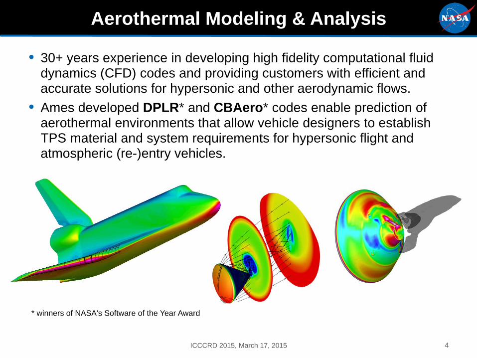
Aerothermal Modeling & Analysis
• 30+ years experience in developing high fidelity computational fluid dynamics (CFD) codes and providing customers with efficient and accurate solutions for hypersonic and other aerodynamic flows.
• Ames developed DPLR* and CBAero* codes enable prediction of aerothermal environments that allow vehicle designers to establish TPS material and system requirements for hypersonic flight and atmospheric (re-)entry vehicles.
ICCCRD 2015, March 17, 2015

5
TPS Thermal-Mechanical Analysis Objectives
• Thermal-mechanical analyses are usually performed in support of major NASA missions, experimental vehicle development projects and advanced material development programs:- Orion & MSL TPS design- X-37 wing leading edge design- Arc-jet pre-test analysis for these and other programs
• The analyses objectives cover a wide variety of topics:- Thermal and mechanical response predictions of in-flight (reentry)
TPS component response- Thermal and mechanical response predictions of ground test (arc-
jet) response of TPS samples- Parametric analyses of material performance for advanced material
concepts – "what if?" analyses
ICCCRD 2015, March 17, 2015
6
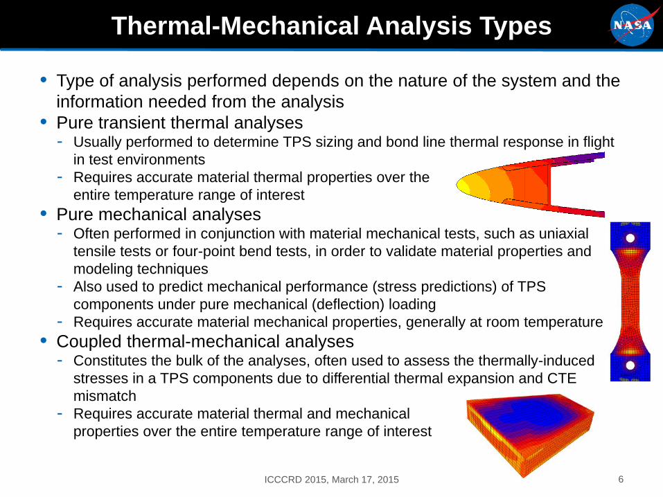
Thermal-Mechanical Analysis Types
• Type of analysis performed depends on the nature of the system and the information needed from the analysis
• Pure transient thermal analyses- Usually performed to determine TPS sizing and bond line thermal response in flight
in test environments- Requires accurate material thermal properties over the
entire temperature range of interest• Pure mechanical analyses
- Often performed in conjunction with material mechanical tests, such as uniaxial tensile tests or four-point bend tests, in order to validate material properties and modeling techniques
- Also used to predict mechanical performance (stress predictions) of TPS components under pure mechanical (deflection) loading
- Requires accurate material mechanical properties, generally at room temperature• Coupled thermal-mechanical analyses
- Constitutes the bulk of the analyses, often used to assess the thermally-induced stresses in a TPS components due to differential thermal expansion and CTE mismatch
- Requires accurate material thermal and mechanical properties over the entire temperature range of interest
ICCCRD 2015, March 17, 2015

7
Thermal-Mechanical Analysis Requirements
• Thermal-mechanical analyses require a minimal set of inputs gathered from various sources- Clear analysis objective from the program – what question does the
analysis need to answer and how good does that answer need to be
- Geometry definition appropriate for the level of analysis needed Usually provided by a program design team
- Complete set of accurate thermal and mechanical properties for all of the materials in the model This is generally the most difficult and time-consuming set of inputs to
gather, often assumptions and approximations are required after consolation with material experts
This includes properties not directly used in the analyses, but required for interpretation of the results, such as tensile strength
- Thermal and mechanical environmental and boundary conditions appropriate for the model Usually provided by a CFD or aerodynamics team
ICCCRD 2015, March 17, 2015

8
Thermal-Mechanical Analysis Tools
• Primary finite element (FE) analysis tool is MSC.Marc, which also includes a pre- and post-processor MSC.Mentat- Marc is a fully non-linear thermal/mechanical analysis package that
can perform thermal, mechanical and coupled thermal/mechanical FE analyses
- Supports a wide variety of material models, including orthotropic materials with temperature-dependent thermal and mechanical properties (a common type of material the TPS field)
• Also using MSC.Nastran, along with the pre- and post-processor MSC.Patran- Nastran is a finite element analysis package that has many of the
same capabilities as Marc, but generally has a wider user base - Motivation for using Nastran was to allow for a higher level of
compatibility with other NASA centers and industry partners
ICCCRD 2015, March 17, 2015

3000
2500
2000
1500
1000
500
0
Temp (°F)
Example: TUFROC swept cylinder arc jet test predictions9
Thermal Mechanical Analysis
• Finite element analysis techniques predict thermal and mechanical performance of TPS components
ICCCRD 2015, March 17, 2015
10
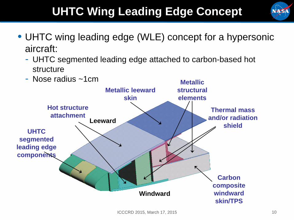
UHTC Wing Leading Edge Concept
• UHTC wing leading edge (WLE) concept for a hypersonic aircraft:- UHTC segmented leading edge attached to carbon-based hot
structure- Nose radius ~1cm
UHTC segmented
leading edge components
Hot structure attachment
Thermal mass and/or radiation
shield
Metallic structural elements
Metallic leeward skin
Leeward
Windward
Carbon composite windward skin/TPS
ICCCRD 2015, March 17, 2015

11
Example of Predicted UHTCWLE Component Performance
• UHTC WLE under reentry heating conditions• Peak predicted thermal stress of 80 MPa was well below
demonstrated UHTC strengths between 300 to 400 MPa
Max Principal Stress Contours
Temperature Contours
8.102e+07
-3.189e+07
2.482e+03
1.580e+03
2.482e+03
1.580e+03
ICCCRD 2015, March 17, 2015

2D axi-symmetric FEMs with nonlinear transient thermal analysis (MARC )
Pre-test analysis, FEM_1
Forebody (PICA)
Backshell (LI-2200)
Carrier substructur
e(metal)
DAQ containe
r
DAQ board
Post-test analysis, FEM_2
Charred PICA
Backshell (LI-2200)
DAQ contain
er
Virgin PICA
Carrier substructur
e(metal)
DAQ board
battery
Analytical Approach and Model DevelopmentAnalytical Approach and Model Development-Example
• Parametric studies for material selection, exposure time and TC locations
• Conduction re-radiation based analysis• Conservative estimates: no pyrolysis,
ablation • Heat flux distribution from DPLR,
directly imposed as boundary condition• Battery power imposed on DAQ board
• High fidelity thermal soak post test analysis- Temperature and grid points from 2D
FIAT (TITAN), mapped onto FE model
- Ablation during exposure included- Virgin and Char PICA modeled
separately• Batteries and other components inside
the metal container are included 12ICCCRD 2015, March 17, 2015

13
TPS Material Response Objectives
• Material response analyses are performed in support of vehicle development programs employing ablative TPS and advanced ablative TPS material development programs.
• The purpose of the analyses is generally two-fold:- Development and validation of accurate material response models
requires close collaboration with material developers and test engineers
- Employing accurate material response models to predict material performance in flight environments – TPS sizing analyses
ICCCRD 2015, March 17, 2015

Energy management through material consumption
14
Ablative TPS
• When exposed to atmospheric entry heating conditions, material will pyrolyze (char), and reject heat in the following ways:
• Endothermic decomposition of polymer• Blowing of ablation
products into the boundary layer reduces convective heating
• Formation of char layer and re-radiation
ICCCRD 2015, March 17, 2015

15
Some Definitions
Pyrolysis • An internal, thermal decomposition of the solid
- Endothermic process releases gaseous species- Pyrolysis does not consume species from the boundary layer gas
Ablation • Processes that remove mass from the surface
- Vaporization and sublimation- Reactions of solid or liquid to produce gaseous species- Melt flow- Spall of solid
"failure" modes
ICCCRD 2015, March 17, 2015

Fully Implicit Ablation and Thermal Response Program
FIAT
16
Fully Implicit Ablation and Thermal Response Program
• Industry standard ablative material response modeling tool- 1-D time accurate solution of thermal diffusion - Similar equations to Aerotherm's CMA - Surface ablation- Internal pyrolysis- Greater stability- 2-D and 3-D versions
• Multilayer material stack- TPS, adhesive, insulation,
structure, air gap, etc.- Planar, cylindrical, spherical,
or "general" geometry• Thickness optimization
based on material temp limits
ICCCRD 2015, March 17, 2015

17
Thermal Modeling Challenges
• Many complex phenomena occur simultaneously- The heating environment depends on the surface recession
(shape change) and details of the surface blowing 1-D, 2-D, or 3-D ? Uncoupled, weakly coupled, or strongly coupled?
- Surface materials may melt, vaporize, or react with the gas phase For the same material, the dominant surface phenomena can vary
depending on local environmental conditions and their history- For pyrolyzing solids Properties depend on thermal/chemical history on a local scale Porosity increases, and internal gas flow occurs Does coking occur?
- For materials containing glass Melt may flow, or accumulate, depending on environment and location Local density and composition, and therefore thermal properties, can
vary
ICCCRD 2015, March 17, 2015

18
Modeling Approach
• To the greatest extent possible, use physics- and chemistry-based models (rather than correlations) with parameters that can be obtained from experiments.
• In the solid: - Phase-change reaction
Virgin solid → Charred solid + pyrolysis gas- For these three constituents Macroscale properties from measurements, known chemistry,
and/or established theory• Density, heat capacity or enthalpy, thermal conductivity,
surface emissivity and absorptivity• Specified as function of temperature and, if necessary,
pressure and orientation Thermodynamics from NIST/JANNAF data
• At the surface- Complex surface energy balance- Thermochemical ablation model- Boundary layer heat transfer with blowing corrections
ICCCRD 2015, March 17, 2015

19
Material Response Analysis Tools
There are two main material response tools used, plus a support program
• Fully Implicit Ablation And Thermal Analysis Program (FIAT)- FIAT is a NASA-developed computer program for simulation of one-dimensional
thermal energy transport in a multilayer stack of isotropic materials and structures, which can ablate from the front surface and decompose in depth
- The implicit solution algorithm and general solution technique make the program very stable and robust for application to reusable launch vehicles as well as to planetary entry probes that use newly-developed light-weight ceramic ablators
• Three-Dimensional FIAT- 3D FIAT is a NASA-developed program for simulation of three dimensional thermal
energy transport in heatshield materials that may decompose internally and ablate from the heated surface
- The program is applicable to hypersonic vehicles, planetary entry probes, and test models in hypersonic ground facilities
• Multicomponent Ablation Thermochemistry (MAT) Program- MAT is a NASA-developed program that implements a general theory for ablation
thermochemistry of thermal protection materials with multiple surface species
ICCCRD 2015, March 17, 2015

20
TPS Material Response Requirements
• Material response analyses require a minimal set of inputs gathered from various sources- Accurate data on the chemical composition of the material
components, such as the substrate and impregnate - Measurements of the decomposition of the material under appropriate
environments, such as Thermogravimetric Analysis (TGA) tests to measure mass loss over time
- Physical and thermal properties of both the virgin and fully charred material over the temperature range of interest: density, specific heat, thermal conductivity, heat of formation
- Information about the microstructure and morphology of the material is also useful in determining the appropriateness and accuracy of the response model
• Comparison of material response analyses with ground tests also requires an additional set of information- Accurate definition of the heating environment, such as the surface
heat flux and pressure from arc-jet tests- Accurate pre- and post-test measurements of the test samples, such
as mass loss and surface recession
ICCCRD 2015, March 17, 2015
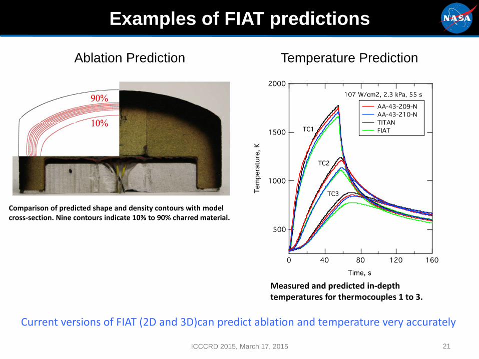
Examples of FIAT predictions
Ablation Prediction Temperature Prediction
21
Comparison of predicted shape and density contours with model cross-section. Nine contours indicate 10% to 90% charred material.
Measured and predicted in-depth temperatures for thermocouples 1 to 3.
Current versions of FIAT (2D and 3D)can predict ablation and temperature very accurately
ICCCRD 2015, March 17, 2015
22
Modeling Summary
• Predict thermal and mechanical response of TPS to environment during entry into an atmosphere
• Develop materials response models• Understand and predict behavior in testing and in flight• Sizing of TPS: want to optimize amount of material and
type of material• Have tools for all of the above• Tools are constantly under development
ICCCRD 2015, March 17, 2015
23
Outline
• Introduction• Modeling
- Thermostructural modeling of TPS- Materials Response modeling of TPS
• Overview of materials computations- TPS- Batteries
ICCCRD 2015, March 17, 2015

24
Computational Materials Modeling of TPS
Chemistry
A B I N I T I O
Physics
A T O M I S T I C
Material Science
C O N T I N U U M
Computational Materials Modeling of TPS
• Design materials for specific applications using advanced modeling methods
• Integrate different scales: - Chemistry- Physics- Continuum
ICCCRD 2015, March 17, 2015

Fourier’s Law
Example: UHTC Thermal Conductivity
25
Example: UHTC Thermal Conductivity
• Determine effect of UHTC grain boundary network on thermal conductivity
• Microstructure FEM model built on SEM image• Material thermal parameters from atomistic simulations• Establish steady state• Evaluate “effective” thermal conductivity (keff)
ICCCRD 2015, March 17, 2015

National Aeronautics and Space Administration
Ames Research CenterEntry Systems and Technology Division

• Transition to computational presentation• (different presentation
27ICCCRD 2015, March 17, 2015

Back up
28ICCCRD 2015, March 17, 2015