NASA · located 0.381 meter aft of the ... k^c . rolling moment due to roll displacement parameter,...
85
NASA Technical Memorandum 74058 Transonic Static and Dynamic Stability Characteristics of a Finned Projectile Configuration Richmond P. Boyden, Cuyler W. Brooks, Jr., and Edwin E. Davenport APRIL 1978 NASA LM156392E 7 JP- / / 0 I https://ntrs.nasa.gov/search.jsp?R=19780012129 2018-06-08T18:46:02+00:00Z
Transcript of NASA · located 0.381 meter aft of the ... k^c . rolling moment due to roll displacement parameter,...

NASA Technical Memorandum 74058
Transonic Static and DynamicStability Characteristics ofa Finned Projectile Configuration
Richmond P. Boyden, Cuyler W. Brooks, Jr.,and Edwin E. Davenport
APRIL 1978
NASA
LM156392E
7 JP- // 0 I
https://ntrs.nasa.gov/search.jsp?R=19780012129 2018-06-08T18:46:02+00:00Z
NASA Technical Memorandum 74058
Transonic Static and DynamicStability Characteristics ofa Finned Projectile Configuration
Richmond P. Boyden, Cuyler W. Brooks, Jr.,and Edwin E. DavenportLangley Research CenterHampton, Virginia
NASANational Aeronauticsand Space Administration
Scientific and TechnicalInformation Office
1978

SUMMARY
Static and dynamic stability tests have been made of a finned projectileconfiguration with aft-mounted fins arranged in a cruciform pattern. The testswere made at free-stream Mach numbers of 0.7, 0.9, 1.1, and 1.2 in the Langley8-foot transonic pressure tunnel. Some of the parameters measured during thetests were lift, drag, pitching moment, pitch damping, and roll damping. Con-figurations tested include the basic configuration with (1) fins deployed,(2) fins deflected for control, and (3) fins removed to simulate the projectilewith the fins folded within the body. The finned projectile was statically sta-ble at low angles of attack, but the stability decreased and became neutral orslightly unstable as the angle of attack was increased. The model had positivedamping in pitch for a free-stream Mach number of 0.7, but there were regionsof negative damping at the other Mach numbers for the various model roll orien-tations. The finned projectile generally had positive damping in roll. Theo-retical estimates showed a lack of agreement with experimental pitching-momentand normal-force derivatives for the fins-on configuration; however, good agree-ment was obtained for the roll damping case.
INTRODUCTION
In cooperation with the U.S. Navy, the NASA Langley Research Center hasmeasured experimentally the static and dynamic stability characteristics of afinned projectile in the transonic speed range. The projectile was designedto be gun launched with the fins folded within the body. After the projectileis launched, the fins fold out and damp out the rolling motion which is impartedto the projectile by the helical grooves in the gun barrel. The fins are thenused as control surfaces to correct the flight of the projectile as the projec-tile is guided toward the intended target.
Tests were made at free-stream Mach numbers of 0.7, 0.9, 1.1, and 1.2 tomeasure lift, drag, and pitching moment; tests for pitch damping and roll damp-ing followed. Other parameters measured during the tests include the oscilla-tory longitudinal-stability parameter, the rolling moment due to roll displace-ment parameter, the normal force due to pitch rate parameter, and the normalforce due to pitch displacement parameter. Configurations tested include thebasic configuration with (1) fins deployed, (2) fins deflected for control,and (3) fins removed to simulate the projectile with the fins folded withinthe body. A full-scale model was used for these tests.
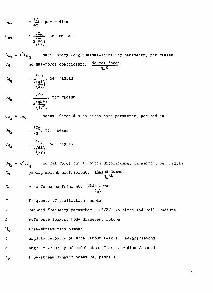
SYMBOLS
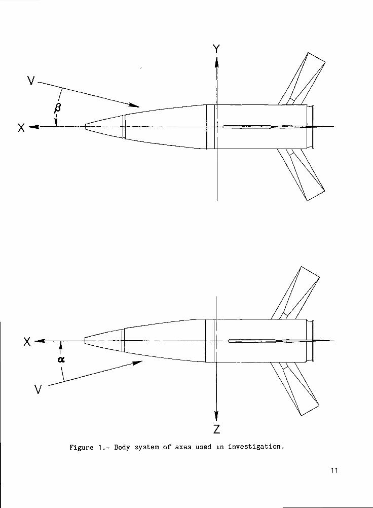
The aerodynamic parameters are referred to the body system of axes as shownin figure 1 except for the lift and drag coefficients which are referred to thestability axes. The axes originate at the assumed center of gravity which was

located 0.381 meter aft of the model nose. The reference length used to non-dimensionalize all of the aerodynamic parameters was the body diameter of0.127 meter, and the reference area was the model base area of 0.0126? meter^.
CD drag coefficient, Drag force
CL lift coefficient, Lift forceqooS
C, rolling-moment coefficient, Rolling momentqooS!l
s r- :!_, per radian
3C per ratiian
C^ + G!-; sin a damping-in-roll parameter, per radian
9CC10 = — I, per radianP 33
C, • = 1 , per radian3
2V
C, D sin a - k^c . rolling moment due to roll displacement parameter,D P •per radian
Cm pitching-moment coefficient, Pitching moment
mGUI = m , per radianq N
per radian
cma + cm,; damping-in-pitch parameter, per radian
3c
, per radian
SL-, per radian
2V;
C- - k C . oscillatory longitudinal-stability parameter, per radian
CN normal-force coefficient, Normal^force
cN SJXNq a(a*V(*)'
9 rCM. = per radian
q
N + CN<V normal force due to pitch rate parameter, per radian
M = .—N, per radian
, per radian
CM - UCM. normal force due to pitch displacement parameter, per radian
Cn yawing-moment coefficient, Yawing moment
CY side-force coefficient, Side force
f frequency of oscillation, hertz
k reduced frequency parameter, 0)£/2V in pitch and roll, radians
& reference length, body diameter, meters
M^ free-stream Mach number
p angular velocity of model about X-axis, radians/second
q angular velocity of model about Y-axis, radians/second
q^ free-stream dynamic pressure, pascals
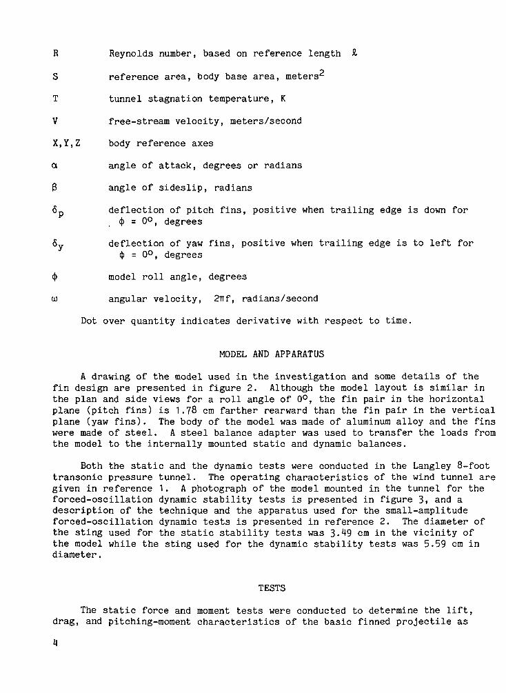
R Reynolds number, based on reference length &
S reference area, body base area, meters^
T tunnel stagnation temperature, K
V free-stream velocity, meters/second
X,Y,Z body reference axes
a angle of attack, degrees or radians
3 angle of sideslip, radians
6p deflection of pitch fins, positive when trailing edge is down for<|> = 0°, degrees
6y deflection of yaw fins, positive when trailing edge is to left for<J> = 0°, degrees
4> model roll angle, degrees
0) angular velocity, 2irf, radians/second
Dot over quantity indicates derivative with respect to time.
MODEL AND APPARATUS
A drawing of the model used in the investigation and some details of thefin design are presented in figure 2. Although the model layout is similar inthe plan and side views for a roll angle of 0°, the fin pair in the horizontalplane (pitch fins) is 1.?8 cm farther rearward than the fin pair in the verticalplane (yaw fins). The body of the model was made of aluminum alloy and the finswere made of steel. A steel balance adapter was used to transfer the loads fromthe model to the internally mounted static and dynamic balances.
Both the static and the dynamic tests were conducted in the Langley 8-foottransonic pressure tunnel. The operating characteristics of the wind tunnel aregiven in reference 1. A photograph of the model mounted in the tunnel for theforced-oscillation dynamic stability tests is presented in figure 3, and adescription of the technique and the apparatus used for the small-amplitudeforced-oscillation dynamic tests is presented in reference 2. The diameter ofthe sting used for the static stability tests was 3. 9 cm in the vicinity ofthe model while the sting used for the dynamic stability tests was 5.59 cm indiameter.
TESTS
The static force and moment tests were conducted to determine the lift,drag, and pitching-moment characteristics of the basic finned projectile as
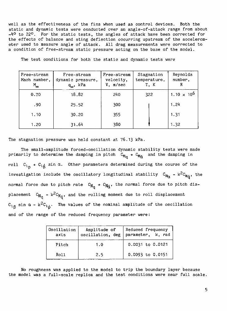
well as the effectiveness of the fins when used as control devices. Both thestatic and dynamic tests were conducted over an angle-of-attack range from about-4° to 22°. For the static tests, the angles of attack have been corrected forthe effects of balance and sting deflection occurring upstream of the accelerom-eter used to measure angle of attack. All drag measurements were corrected toa condition of free-stream static pressure acting on the base of the model.
The test conditions for both the static and dynamic tests were
Free-streamMach number,
M«,
0.70
.90
1.10
1.20
Free-streamdynamic pressure,
q«. kPa
18.82
25.52
30.20
31.64
Free-streamvelocity,V, m/sec
240
300
355
380
Stagnationtemperature ,
T, K
322
Reynoldsnumber ,
R
1.10 x 10⁶
1.24
1.31
1.32
The stagnation pressure was held constant at 76.13 kPa.
The small-amplitude forced-oscillation dynamic stability tests were madeprimarily to determine the damping in pitch
roll G
+ C™, and the damping in
+ Cl3 sin a. Other parameters determined during the course of thel(3
investigation include the oscillatory longitudinal stability C™ - k^Cm. , the
normal force due to pitch rate CN + CM., the normal force due to pitch dis-
placement CM, - kCfl., and the rolling moment due to roll displacement
ClR sin a - kC^ . . The values of the nominal amplitude of the oscillation
and of the range of the reduced frequency parameter were :
Oscillationaxis
Pitch
Roll
Amplitude ofoscillation, deg
1.0
2.5
Reduced frequencyparameter , k , rad
0.0031 to 0.0121
0.0093 to 0.0151
No roughness was applied to the model to trip the boundary layer becausethe model was a full-scale replica and the test conditions were near full scale.

PRESENTATION OF RESULTS
The experimental results are presented for the various parameters by figurenumber as follows:
Parameters
CT Cn C™
Ci Cn Cv .
^q + Cmd' Cma ~ k q ' ' 'cNq + CNd, CNa - k
2CN^ . . .
Clp + C^ sin a,
C, sin a - k^C,
Effect of -
Fins onand offat -
<}) = 0°
4
11
11
Modelrollangle
5
12
15
17
Deflectionof pitchfins at -
$ = 0°
6
13
16
18
Deflectionof yaw fins
at -
$ = QO
7
10
19
$ = 90°
8
Deflectionof pitchand yawfins at -
4> = 45°
9
RESULTS AND DISCUSSION
Static Tests
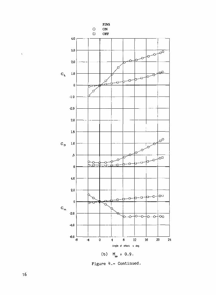
The results from the static force and moment tests of the firined projectilemodel are contained in figures U to 10. The effect of the fins on the staticlongitudinal characteristics of the model is shown in figure 4. The body withthe fins on is seen to be statically stable over the low angle-of-attack range,but the stability decreases and becomes neutral or somewhat unstable as theangle of attack is increased. The body without the fins is slightly unstablefor the reference center-of-gravity position.
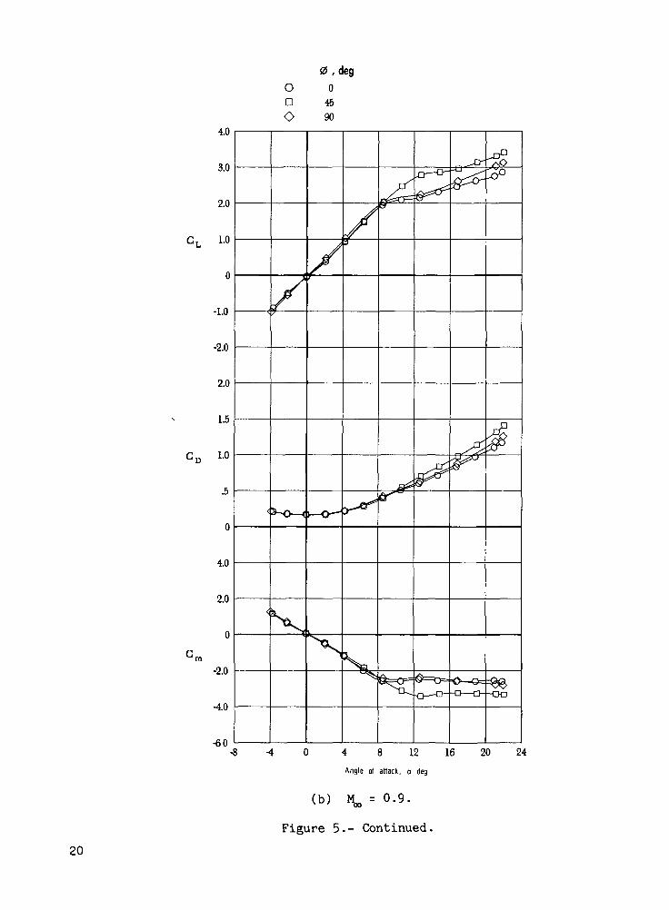
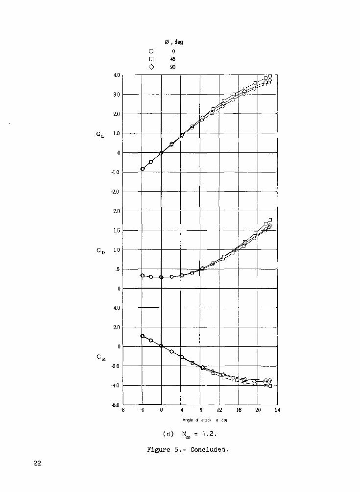
Figure 5 shows the result of varying the model roll angle on the staticlongitudinal characteristics. Although the model layout is similar in the planand side views for a roll angle of 0°, the fin pair in the horizontal plane(pitch fins) is 1.78 cm farther rearward than the fin pair in the vertical plane(yaw fins, see fig. 2). At a roll angle of 0° the rearmost pair of fins lies inthe horizontal plane. The fin orientation for a roll angle of 45° is seen to bethe most effective aerodynamically of the various roll angles tested because itresults in the highest lift coefficients and provides static stability over thelargest angle-of-attack range.

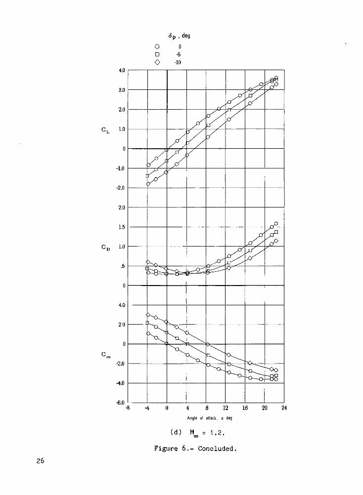
The effect of deflection of the pitch fins on the static longitudinal char-acteristics is shown in figure 6 for a roll angle of 0°. A pitch fin deflectionof -10° (trailing edge up) is seen to trim the model in the range between 8° and10° over the free-stream Mach number range of 0.7 to 1.2. For the Mach numbersof 0.7 and 0.9, deflection of the pitch fins becomes ineffective at angles ofattack between 12° and 16° for a maximum deflection of -10°. For a Mach numberof 1.1, the pitch fins begin to lose their effectiveness at an angle of attackof about 19° but at M^ = 1.2 the pitch fins are still effective at about 22°,the highest angle of attack tested.
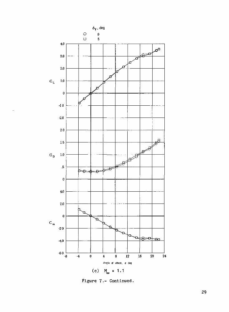
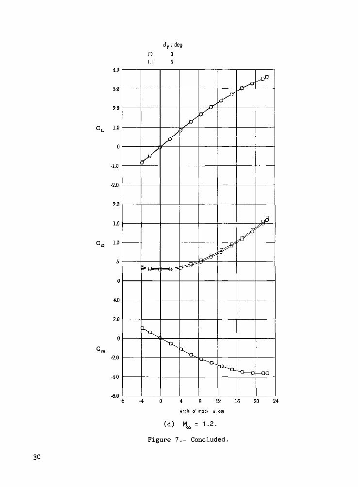
The only effect on the static longitudinal characteristics of a deflectionof the yaw fins for a model roll angle of 0° is a small increase in the dragcoefficient as shown in figure 7.
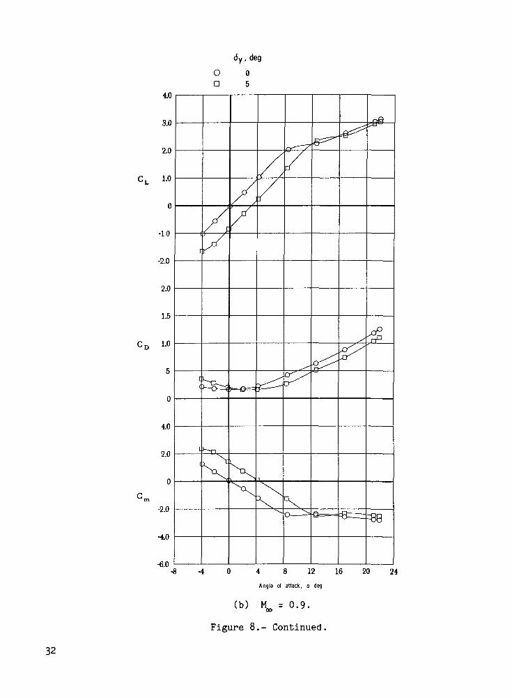
As figure 8 shows, for a model roll angle of 90°, the deflection of theyaw fins for pitch control resulted in static longitudinal characteristicsalmost identical to those achieved by the deflection of the pitch fins for 0°model roll angle (see fig. 6). The small longitudinal separation of the twopairs of fins did not seem to cause any dissimilar aerodynamic interferencebetween the fin pairs as a result of different roll angles.
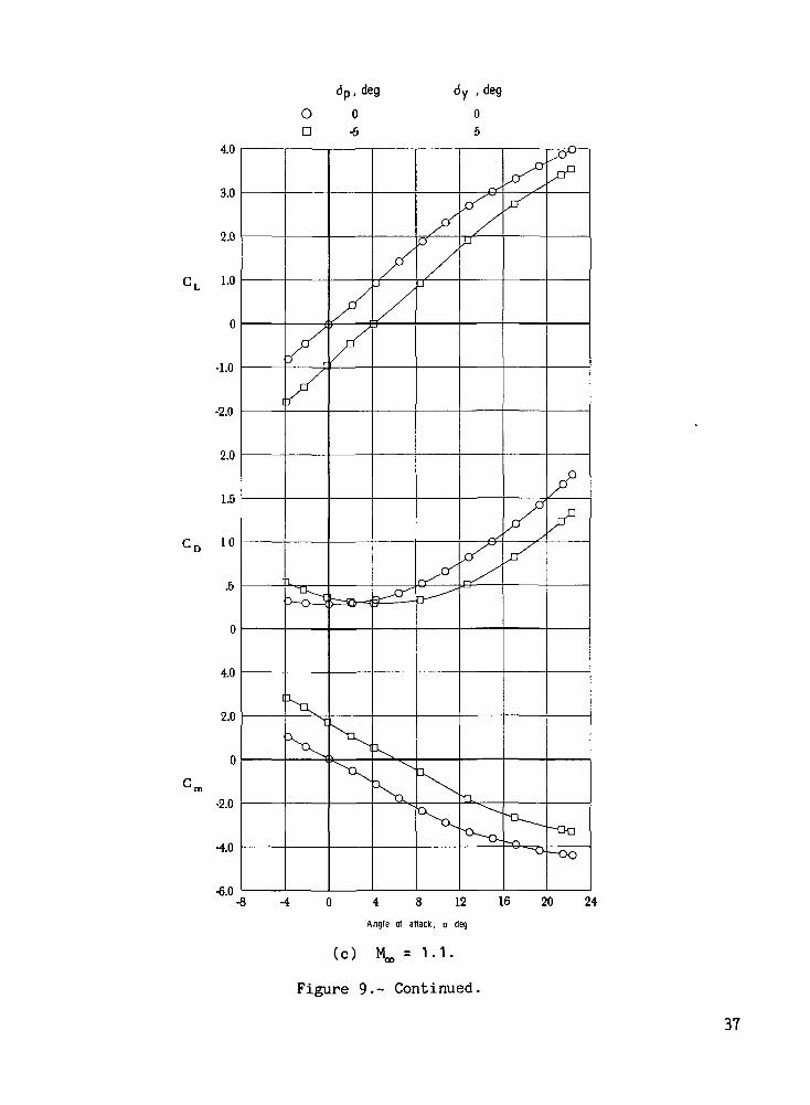
Combined pitch and yaw fin deflection for a 45° model roll angle shown infigure 9 indicates that in this position the fins are more effective as pitchcontrol devices than pitch fins alone at a 0° roll angle. The combined pitchand yaw fin deflection is also effective to higher angles of attack. Thus forthe same amount of fin deflection, a higher trim angle of attack can be achievedat a roll angle of 45° when compared to a roll angle of 0°. (Compare figs. 6and 9.)
The only static lateral characteristics presented for the finned projectilemodel are shown in figure 10. The effect of a 5° deflection of the yaw finswith the model at a roll angle of 0° indicates that there is a large amount ofyawing moment available with very little resultant rolling moment.
Dynamic Tests
The test results for damping-in-pitch parameter Cm + C^- and the oscilla-M
tory longitudinal-stability parameter C™ - k^Cjg. are shown in figures 11 to
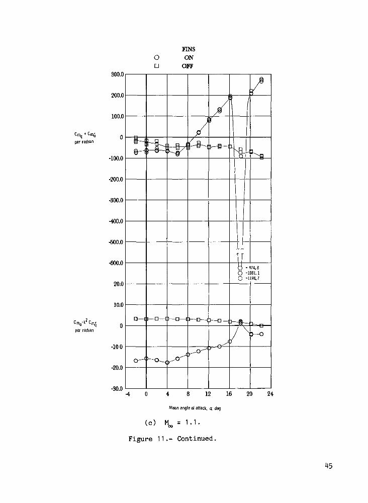
13 for the various configurations. A comparison for the fins on and off is con-tained in figure 11. This figure shows that the fins-on configuration has posi-tive damping in pitch I negative values of CL + Cmr\ for the subsonic free-^ <j ^jt i
stream Mach numbers. There are regions of negative damping for the Mach numbersof 1.1 and 1.2 above a 10° angle of attack for the fins-on configuration. Thefins-off configuration had positive damping in pitch over the entire ranges ofboth angle of attack and Mach number. The oscillatory longitudinal stability isseen to decrease above an angle of attack of 4° for the fins-on configuration;and, except for M^ = 1.2, there were some regions of negative oscillatory lon-gitudinal stability (positive values of C,- - k Cjjj.V With the fins removed,
\ * *

the body has negative oscillatory stability in pitch at all test conditionsexcept at the highest angle of attack for Mach numbers of 1 . 1 and 1.2.
The effect of the roll angle of the model on the damping in pitch is shownin figure 12 for roll angles of 0°, 45°, and 90°. The results for the rollangles of 0° and 90° generally appear to be similar except for some differencesat the higher angles of attack, and the trends for the 45° roll angle resultswith the fins oriented in an "X" configuration tend to be different from theother two roll angles. For example, for a free-stream Mach number of 0.9 the45° roll angle configuration had negative damping in pitch above a 16° angle ofattack, whereas the 0° and 90° configurations had positive damping in pitchover the entire range of angle of attack. The increased effectiveness of thefins for the roll angle of 45° is evident for angles of attack between 6° and12° in the oscillatory longitudinal stability results shown in figure 12.
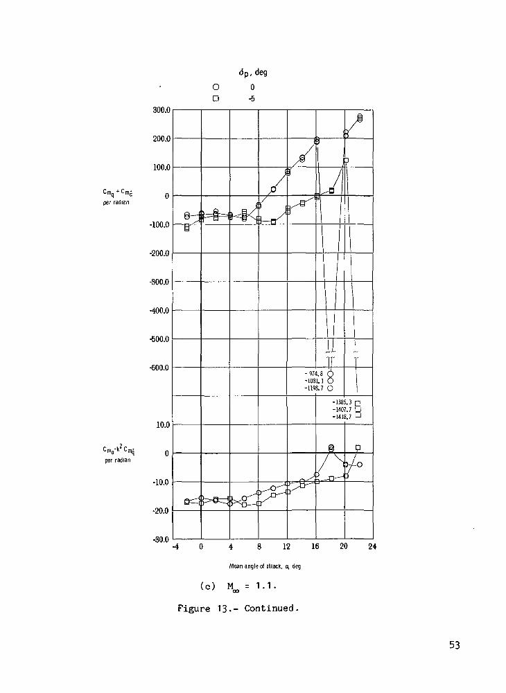
The effect of deflecting the pitch fins -5° (trailing edge up) is containedin figure 13. For the Mach numbers of 0.7, 0.9, and to a lesser extent 1.1, thedata appear as though they had been shifted 4° to 5° in angle of attack as aresult of the pitch fin deflection of -5°. The effect is noticeable in both thepitch damping and the oscillatory longitudinal-stability results.
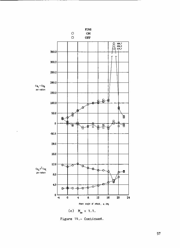
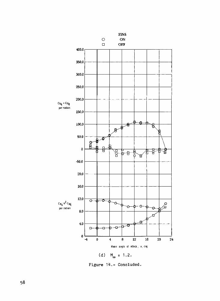
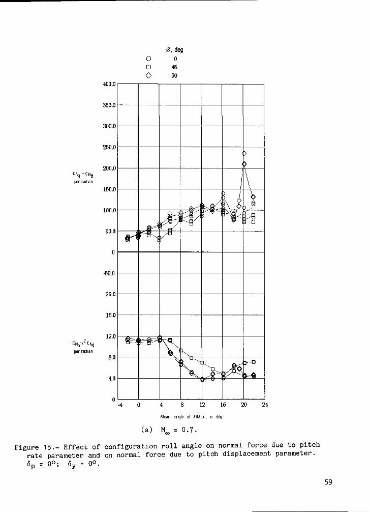
Presented in figures 14 to 16 are the results for the normal force due topitch rate parameter Cjj + CJT- and the normal force due to pitch displacement
parameter Cjj - kCfj for the same configurations shown in figures 11 and 13-
The basic finned body has positive values of the normal force due to pitch rateover the entire range of angle of attack and free-stream Mach number. The bodywith the fins removed had small positive and negative values for CM + CMJ.
The results for the different roll angles shown in figure 15 generally have thesame trends with angle of attack.
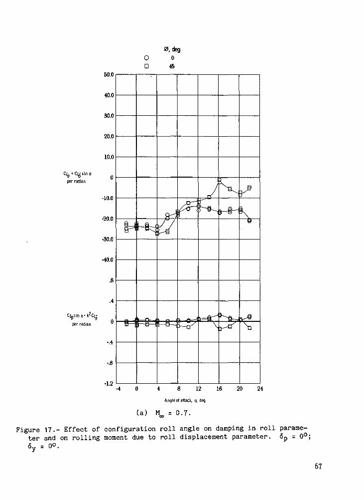
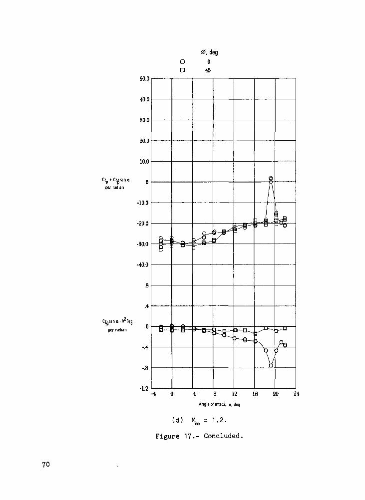
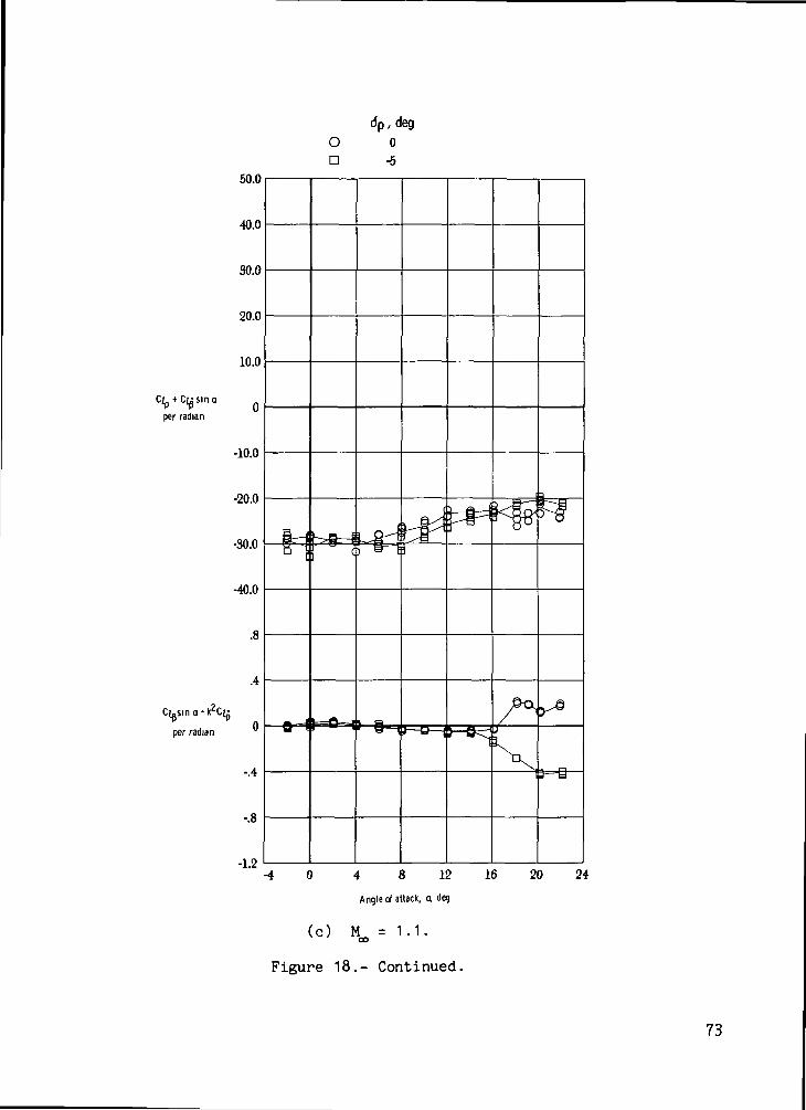
The results for the damping in roll parameter C-^ + CID sin a an^ for tne
rolling moment due to roll displacement parameter C-^n sin a - k' . are shown
in figures 17 to 19. Generally the damping in roll is larger for 4> = 45° thanfor (j) = 0° up to an angle of attack between 8° and 10°; above this anglerange the 0° roll angle configuration had more roll damping. Negative dampingin roll /positive CT + C^ sin a\ occurred for the 45° roll angle at M^ = 0.9
at angles of attack near 12° to 15°. Figure 18 shows that the damping in rolldid not fall off as much for <5p = -5° as it did for <Sg = 0° in the 6° to 12°angle-of-attack range for Mach numbers of 0.7 and 0.9. This difference in rolldamping is a result of the lower effective angle of attack of the pitch fins.In figure 19, a 5° deflection of the yaw fins resulted in slightly more rolldamping over most of the angle-of-attack range.

Theoretical Estimates Compared With Static and
Dynamic Experimental Results
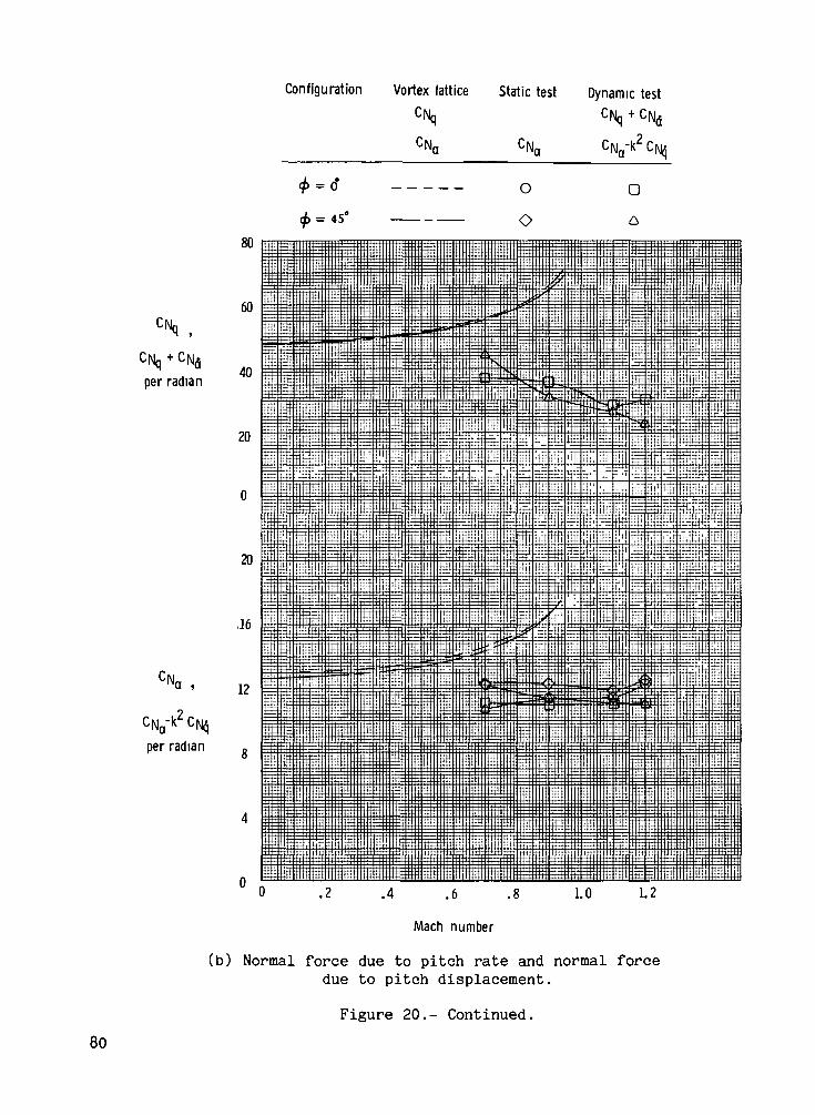
A vortex-lattice computer program based on the work in reference 3 wasused to make theoretical estimates of the subsonic aerodynamic stability deriva-tives for comparison with the experimentally determined derivatives. The com-puter program had been modified to include a provision for modeling a cylindri-cal fuselage with up to three lifting surfaces. The projectile body was modeledas an open-ended circular cylinder of the same length as the original projectilebody. The results of the vortex-lattice program are based on the assumption ofan attached flow condition and are therefore only valid in the linear range ofthe lift-curve slope.
Figure 20 contains a comparison of the vortex-lattice theoretical estimateswith the static and dynamic experimental results for the fins-on configurationfor roll angles of both 0° and 45°. The stability derivatives shown in fig-ure 20 for the static data were determined from the slope at a = 0° of aspline fit to the experimental data, and the stability parameters from thedynamic test are an average of the individual data points at a = 0°. Fig-ure 20(a) is a comparison between the experimentally determined pitching-momentparameters and the theoretical estimates. In the top half of figure 20(a), thevortex-lattice C^ estimates are seen to overpredict the damping in pitch
parameter (^ + Cm. measured at subsonic speeds for both the 0° and 45° roll
angle configurations. In the bottom half of figure 20(a), the static anddynamic results for the longitudinal stability are seen to be in good agreement.However, the vortex-lattice results for Cm have a negative slope with free-
stream Mach number while the experimental results have essentially a zero slopewith free-stream Mach number.
The comparison for the normal-force parameters is shown in figure 20(b)where the vortex-lattice estimates were larger than the experimental results forboth the normal force due to pitch rate and the normal force due to pitch dis-placement. There was good agreement between the static test values of CM andthe dynamic test values of C^ - k^Cn..
The comparison of the theoretical estimates with the experimental resultsfor the damping in roll is shown in figure 20(c), and good agreement is seenbetween the theoretical and experimental values. Since all of figure 20 isfor a = 0°, the second term of the experimental damping-in-roll parameterC, + C-i A sin a should be zero.P P
The reason for the lack of agreement between the vortex-lattice estimatesand the experimental results for the pitching-moment and normal-force deriva-tives is thought to be a result of the simplified modeling of the body for thecomputer program. The assumption of an open-ended cylindrical body could haveaffected the pitching-moment and normal-force estimates while still giving goodagreement for the roll damping.

SUMMARY OF RESULTS
An investigation has been made to determine the static and dynamic stabil-ity characteristics of a full-scale model of a finned projectile configuration.These tests were made at angles of attack from -1° to 22° and at free-streamMach numbers of 0.7, 0.9, 1.1, and 1.2. The results may be summarized asfollows:
1. The finned projectile was statically stable at low angles of attack, butthe stability decreased and became neutral or slightly unstable as the angle ofattack was increased.
2. A roll angle of 45°, when compared to 0° or 90°, was the most effectiveaerodynamically because it resulted in the highest lift coefficients and pro-vided static stability over the largest angle-of-attack range.
3. The finned projectile had positive damping in pitch for a free-streamMach number of 0.7, but there were regions of negative damping at the other free-stream Mach numbers for the various model roll orientations.
4. The model generally had positive damping in roll except between 12° and15° angle of attack for a roll angle of 45° and a free-stream Mach number of 0.9.
5. The theoretical estimates showed a lack of agreement with the experimen-tal pitching-moment and normal-force derivatives for the fins-on configuration.However, good agreement was obtained for the roll damping case.
Langley Research CenterNational Aeronautics and Space AdministrationHampton, VA 23665March 6, 1978
REFERENCES
1. Schaefer, William T., Jr.: Characteristics of Major Active Wind Tunnels atthe Langley Research Center. NASA TM X-1130, 1965.
2. Freeman, Delma C., Jr.; Boyden, Richmond P.; and Davenport, E. E.: Super-sonic Dynamic Stability Characteristics of a Space Shuttle Orbiter. NASATN D-8043, 1976.
3. Lamar, John E.; and Gloss, Blair B.: Subsonic Aerodynamic Characteristicsof Interacting Lifting Surfaces With Separated Flow Around Sharp Edges Pre-dicted by a Vortex-Lattice Method. NASA TN D-7921, 1975.
10
V
Figure 1.- Body system of axes used in investigation.
11

o•HJ->rt
3bO•HCM
OO
0>•OOs0)-pQ)rHaBoo
•H
rtCH•a
I00S-,
H
c•H
0)t,(0
n§•HWC
0)g
•H
d)•oi
CwO
wi-H•H
12

0.05 radius
FIN PIVOT AXIS
(b) Fin details.
Figure 2.- Concluded.
13

14

4.0
3.0
2.0
GL 1.0
0
-1.0
-2.0
2.0
1.5
CD 1.0
.5
4.0
2.0
-2.0
-4.0
-60
FINSO OND OFF
16 20 24D 4 8 12
Angle of attack a deg
(a) M = 0.7.
Figure 4.- Effect of tail fins on static longitudinal characteristics.4, = 00; 6p = 0°; 6y = 0°.
15
4.0
3.0
2.0
CL 1.0
-10
-2.0
2.0
1.5
4.0
2.0
-2.0
4.0
-6.0
FINSO OND OFF
- 8 4 0 4 8 1 2 1 6
Angle of attack a deg
(b) M = 0.9.CO
Figure U.- Continued.
20 24
16

40
3.0
2.0
CL 1.0
-1.0
-2.0
2.0
1.5
.5
4.0
2.0
-2.0
-4.0
-6.0
FINSO OND OFF
- 8 - 4 0 4 8 1 2 1 6
Angle of attack, a deg
(c) M = 1 . 1 .CO
Figure 4.- Continued.
20 24
17

4.0
3.0
2.0
GL 1.0
0
-1.0
-2.0
2.0
1.5
CD 1.0
4.0
2.0
-2.0
-4.0
-6.0
FINSO OND OFF
.cr
- 8 - 4 0 4 8 1 2 1 6
Angle of attack, a, deg
(d) M = 1.2.OO
Figure 4.- Concluded.
20 24
18

4.0
3.0
20
GL 1.0
-1.0
-2.0
20
15
CD 10
40
2.0
-20
-4.0
-60-8
OD
O
0 , deg
04590
4 8 12 16 20
Angle of attack, a deg
24
(a )
Figure 5.- Effect of configuration roll angle on static longitudinalcharacteristics. 5p = 0°; 6y = 0°.
19
4.0
3.0
2.0
CL 1.0
0
-1.0
-2.0
2.0
1.5
.5
4.0
2.0
-2.0
-4.0
-60
O
D
O
0 , deg
0
45
90
• 8 - 4 0 4 8 1 2 1 6
Angle of attack, a deg
(b) ^ = 0.9.
Figure 5.- Continued.
20 24
20

4.0
3.0
2.0
CL 1.0
-1.0
-2.0
2.0
1.5
CD 1.0
4.0
2.0
-2.0
-4.0
-6.0
OD
O
0 , deg
04590
• 8 - 4 0 4 8 1 2 1 6
Angle of attack a. deg
(c) M^ = 1.1.
Figure 5.- Continued.
20 24
21
4.0
30
2.0
GL 1.0
-10
-2.0
2.0
1.5
GD 10
.5
0
4.0
2.0
-20
-40
-6.0
0 , deg
O 0D 45
O 90
DO -
- 8 - 4 0 4 8 1 2 1 6
Angle of attack a deg
(d) M^ = 1.2.
Figure 5.- Concluded.
20 24
22

4.0
30
2.0
CL 1.0
-10
-20
2.0
1.5
CD 10
40
20
-2.0
-4.0
-60
dp, deg
O 0
D -5
O -10
16 20 24- 8 - 4 0 4 8 1 2
Angle of attack a deg
(a) M^ = 0.7.
Figure 6.- Effect of pitch fin deflection on static longitudinalcharacteristics. § - 0°; 6 = 0°.
23

4.0
3.0
2.0
CL 1.0
0
-1.0
-2.0
2.0
1.5
CD 1-0
4.0
2.0
0
-2.0
-4.0
-6.0
dp, deg
O 0D -5O -10
• 8 - 4 0 4 8 1 2 1 6
Angle of attack, a. deg
(b) M^ = 0.9.
Figure 6.- Continued.
20 24

-604 8 12 16
Angle of attack, a deg
20 24
(O M = 1.1.CO
Figure 6.- Continued.
25
4.0
3.0
2.0
GL 1.0
0
-1.0
-2.0
2.0
1.5
.5
C
4.0
20
0
-2.0
-4.0
-6.0-8
6p , deg
O 0D -5
O -10
4 8 12 16
Angle of attack, a deg
20 24
(d) M = 1.2.oo
Figure 6.- Concluded.
26

40
30
20
GL 10
0
-10
-2.0
2.0
1.5
GD 1.0
40
2.0
-2.0
-4.0
-6.0-8
OD
, deg
05
(a)
4 8 12 16
Angle of attack a deg
M = 0.7.
20 24
Figure 7.- Effect of yaw fin deflection on static longitudinalcharacteristics. <J> = 0°; 6p = 0°.
27

4.0
30
2.0
GL 1.0
-1.0
-2.0
2.0
CD 10
4.0
20
-20
-40
-6.0
OD
y, deg
05
- 8 - 4 0 4 8 1 2
Angle of attack, a. deg
(b) M^ = 0.9.
Figure 7.- Continued.
16 20 24
28
4.0
3.0
2.0
GL 1.0
-10
-2.0
20
15
GD 1.0
.5
0
4.0
2.0
-20
-4.0
-60
OD
, deg
05
- 8 - 4 0 4 8 1 2 1 6
Angle of attack, a deg
(c) M^ = 1.1
Figure 7.- Continued.
20 24
29
4.0
3.0
20
CL 1.0
0
-1.0
-2.0
2.0
1.5
GD 1.0
4.0
2.0
-2.0
-40
-6.0-8
OD
, deg
05
(d )
4 8 12 16
Angle of attack a, deg
Mro = 1.2.
20 24
Figure 7.- Concluded.
30

4.0
3.0
2.0
CL 10
-10
-20
2.0
15
4.0
20
-2.0
4.0
-6.0-8
dy, degO 0D 5
(a)
4 8 12 16 20 24
Angle of attack a deg
M = 0.7.
Figure 8.- Effect of yaw fin deflection on static longitudinalcharacteristics. 4> = 90°; 6p = 0°.
31
, deg
4.0
3.0
2.0
CL 1.0
-10
-2.0
2.0
1.5
0
4.0
2.0
0
-2.0
-4.0
-6.0-8
OD
4 8 12 16
Angle of attack, a deg
(b) M = 0.9.
20 24
Figure 8.- Continued.

4.0
3.0
2.0
GL 1.0
0
-1.0
-2.0
2.0
1.5
CD 1-0
4.0
2.0
0
-2.0
-4.0
•6.0-8
OD
, deg
05
-0=
-DO
4 8 12 16
Angle of attack a, deg
20 24
(C) M^ = 1.1.
Figure 8.- Continued.
33

40
30
2.0
GL 1.0
-1.0
-2.0
20
1.5
GD LO
4.0
2.0
0
-2.0
4.0
-6.0
<5y , deg
O 0D 5
-o-
- 8 4 0 4 8 1 2 1 6
Angle of attack, a, deg
(d) M^, = 1.2.
Figure 8.- Concluded.
20 24

4.0
30
2.0
GL 10
0
-1.0
-2.0
2.0
1.5
CD 1.0
4.0
2.0
-2.0
-4.0
-6.0-8
OD
p , deg
0-5
cJy, deg
05
(a)
4 8 12
Angle of attack, o deg
Mm = 0.7.
16 20 24
Figure 9.- Effect of pitch and yaw fin deflection on staticlongitudinal characteristics. <t> =
35

4.0
3.0
2.0
GL 1.0
-1.0
-2.0
2.0
1.5
4.0
2.0
-2.0
4.0
-6.0
dp, cleg
O 0D -5
<5y , cleg
05
- 8 4 0 4 8 1 2 1 6
Angle of attack a deg
(b) ^ = 0.9.
Figure 9.- Continued.
20 24
36
4.0
3.0
2.0
CL 1-0
-1.0
-2.0
2.0
1.5
10
4.0
2.0
•2.0
-4.0
-6.0
dp, deg
O 0
n -5
, deg
0
5
[V
jr
- 8 - 4 0 4 8 1 2 1 6
Angle of attack, o deg
(C) MB, = 1.1.
Figure 9.- Continued.
20 24

4.0
3.0
2.0
CL 1.0
-1.0
-2.0
2.0
1.5
CD 1.0
4.0
2.0
-2.0
-4.0
-6.0
dp, deg
O 0n -5
y, deg
05
- 8 - 4 0 4 8 1 2 1 6
Angle of attack, a, deg
(d) ^ = 1.2.
Figure 9.- Concluded.
-ee-
20 24
38

-.2
-.4
.4
-.4
-.8
-1.2
-1.6
1.2
-.4
OD
, deg
05
3—0—ii=-a—i
•DO
- 8 - 4 0 4 8 1 2 1 6 2 0 2 4
Angle of attack, a, deg
(a) M^ = 0.7.
Figure 10.- Effect of yaw fin deflection on static lateralcharacteristics. <j> = 0°; 6p = 0°.
39

-.4
.4
-.4
-1.2
-1.6
1.2
C, A
-.4
On
U—C
y , deg
05
=O= •H3—UQ
- 4 0 4 8 1 2
Angle of attack, a, deg
(b) M = 0.9.
16 20 24
Figure 10.- Continued.

-.4
.4
-1.2
-1.6
1.2
.4
dy , deg
O 0D 5
"3—u—i r=a
tr
-4 0 4 8 12
Angle of attack, a, deg
(c) M = 1.1.GO
Figure 10.- Continued.
16 20 24

-.4
.4
-.4
-.8
-1.2
-1.6
1.2
.8
-.4
OD
, deg
05
- 8 - 4 0 4 8 12
Angle of attack, a, deg
(d) M = 1.2.OO
Figure 10.- Concluded.
16 20 24

per radian
per radian
HNSO OND OFF
300.0
200.0
100.0
-100.0
•200.0
-300.0
-400.0
-500.0
-600.0
20.0
10.0
-10.0
•20.0
-30.00
o—n—a
8 12 16 20 24
Mean angle of attack, a, deg
(a) H = 0.7.
Figure 11.- Effect of tail fins on damping-in-pitch parameter and on oscillatorylongitudinal-stability parameter. o> = 0°; 6p = 0°; 6y = 0°.

per radian
per radian
oD
300.0
200.0
100.0
-10.0
-20.0
-30.0
HNSON
OFF
0 4 8 12 16
Mean angle of attack, a, deg
(b) M^ = 0.9.
Figure 11.- Continued.
20 24
per radian
per radian
300.0
200.0
100.0
0
-100.0
-200.0
-300.0
-400.0
-500.0
-600.0
20.0
10.0
0
-100
-20.0
.ann
FINS
O ON
D OFF
N-n
D— 1
a-<
ha,,B W Jo — <
1 — D — t
>^X^
/1— S- P-"S~-»] tJ/1
Nr
3— D— I
^
3 t
J-O-H
> °
yr
i— §— i
1
t
1il
If
/
S
H -974.8O -1081.1O -H98.7
J-0-!
, o-"
h~fr-
/ X >— 0
0 4 8 12 16
Mean angle of attack, a, deg
(c) M^ = 1.1.
Figure 11.- Continued.
20 24

per radian
r 1,2 ririg * i-iriq
per radian
300.0
200.0
100.0
-100.0
-200.0
-300.0
-400.0
-500.0
-600.0
20.0
10.0
-10.0
-20.0
-30.0
FINS
O OND OFF
4 0 4 8 1 2 1 6
Mean angle of attack, a, deg
(d) M^ = 1.2.
Figure 11.- Concluded.
20 24

300.0
200.0
100.0
per radian
-100.0
•200.0
-300.0
-400.0
-500.0
•600.0
20.0
10.0
per radian
-10.0
-20.0
-30.0
ODO
0, deg
04590
40 4 8 12 16 20 24
Mean angle of attack, a, deg
(a) M = 0.7.oo
Figure 12.- Effect of configuration roll orientation on damping-in-pitchparameter and on oscillatory longitudinal-stability parameter. 6n = 0°;Sy = 00.
P

per radian
per radian
300.0
200.0
100.0
-100.0
-10.0
-20.0
-30.0
oD
O
0, deg
04590
-40 4 8 12 16
Mean angle of attack, a, deg
(b) M^ = 0.9.
Figure 12.- Continued.

per radian
Cma"k cmqper radian
300.0
•500.0
10.0
-10.0
-20.0
-30.04 8 12 16
Mean angle of attack, a, deg
(c) M = 1.1.
20 24
Figure 12.- Continued.

Cmq + cma
per radian
Cm,,-* Cmq
per radian
300.0
200.0
100.0
-100.0
•200.0
-300.0
-400.0
-500.0
-600.0
20.0
10.0
-10.0
-20.0
-30.08 12 16 20 24
Mean angle of attack, a, deg
(d) M^ = 1.2.
Figure 12.- Concluded.
50

Cmq +Cm5
per radian
per radian
300.0
200.0
100.0
-100.0
-200.0
-300.0
-400.0
-500.0
-600.0
20.0
10.0
-10.0
-20.0
-30.0
dp, deg
O 0D -5
n i,
0 4 8 12 16 20 24
Mean angle of attack, a, deg
(a) M = 0.7.oo
Figure 13.- Effect of pitch fin deflection on damping-in-pitch parameter andon oscillatory longitudinal-stability parameter. $ = 0°; 6y = 0°.
51

per radian
cma-l< Cm-
per radian
300.0
200.0
100.0
-100.0
-200.0
-300.0
-400.0
-500.0
-600.0
10.0
-10.0
-20.0
-30.04 8 12
Mean angle of attack, a, deg
(b) Mro = 0.9.
Figure 13-- Continued.
16 20 24
52
per radian
per radian
300.0
200.0
100.0
0
-100.0
-200.0
-300.0
-400.0
-500.0
-600.0
10.0
0
-10.0
-20.0
.an ft
dp, deg
O 0D -5
*Ji"
0=3
H=i
^^
KKl
*xgd
/^
^ J^M
^-?
/'r
,
^
,
u
111ir
-974. 8 6-1081.1 O-1198.7 O
, Q^^~")cf- —
/3
i
-1385.3 n-1407.7 LJ-1418.7 d
8
£
P
r0 4 8 12 16
Mean angle of attack, a, deg
(c) M a ) = 1.1.
Figure 13.- Continued.
20 24
53

Cmq + Cm|j
per radian
per radian
300.0
200.0
100.0
0
-100.0
-200.0
-300.0
-400.0
-500.0
•600.0
20.0
10.0
0
-10.0
-20.0
.snn
dp, cleg
O 0D -5
<dsr
BM
1— dS=-<^sr \
h-cM
, a/Mr~i
^
/l
/S
r^
s-e^dr T^T
VJO/^E
*£
j
4u
n
^
4 8 12 16
Mean angle of attack, a, deg
(d) M = 1.2.GO
Figure 13.- Concluded.
20 24

per radian
per radian
400.0
350.0
300.0
250.0
200.0
150.0
100.0
50.0
-50.0
20.0
16.0
12.0
8.0
4.0
FINSO OND OFF
-40 4 8 12 16 20 24
Mean angle of attack, a, deg
(a) M_ = 0.7.
Figure 14.- Effect of tail fins on normal force due to pitch rate parameter and on normal force due to pitch displacement parameter. <j> = 0°;Sp = 0°; 6y = 0°.
55

per radian
per radian
400.0
350.0
300.0
250.0
200.0
150.0
100.0
50.0
-50.0
20.0
16.0
12.0
4 8 12 16
Mean angle of attack, a, deg
(b) M = 0.9.QO
Figure 1U.- Continued.
56
per radian
per radian
350.0
300.0
250.0
200.0
150.0
100.0
50.0
-50.0
4 8 12 16
Mean angle of attack, a, deg
(c) M^ = 1.1.
Figure 14.- Continued.
20 24
57
400.0
350.0
300.0
250.0
200.0
per radian
150.0
100.0
50.0
-50.0
20.0
16.0
12.0
per radian8.0
4.0
FINSO OND OFF
0 4 8 12 16
Mean angle of attack, a, deg
(d) M^ = 1.2.
Figure 1U.- Concluded.
20 24
58
400.0
350.0
per radian
per radian
-40 4 8 12 16 20 24
Mean angle of attack, a deg
(a) M = 0.7.
Figure 15.- Effect of configuration roll angle on normal force due to pitchrate parameter and on normal force due to pitch displacement parameter.6p = 0°; 6y = 0°.
59

per radian
400.0
350.0
300.0
250.0
200.0
150.0
100.0
per radian
-50.0
O 4 8 12 16
Mean angle of attack, a, deg
(b) M^ = 0.9.
Figure 15.- Continued.
20 24
60

CNq + %per radian
per radian
300.0
250.0
200.0
150.0
100.0
-50.0
4.0
0 4 8 12 16
Mean angle of attack, a. deg
(c) ^ = 1.1.
Figure 15.- Continued.
61

per radian
400.0
3500
300.0
250.0
200.0
150.0
100.0
per radian
-50.0
0 4 8 12 16
Mean angle of attack, a, deg
(d) M^ = 1.2.
Figure 15.- Concluded.
62

dp, deg
CNq + %
per radian
400.0
350.0
300.0
250.0
200.0
150.0
100.0
50.0
per radian
-50.0
20.0
16.0
12.0
8.0
4.0
OD
0•5
-40 4 8 12 16 20 24
Mean angle of attack, a, deg
(a) M^ = 0.7.
Figure 16.- Effect of pitch fin deflection on normal force due to pitch rateparameter and on normal force* due to pitch displacement parameter. <}> = 0°;6y = QO.
63

per radian
350.0
300.0
250.0
200.0
150.0
100.0
per radian
50.0
-50.0
20.0
16.0
12.0
0 4 8 12 16
Mean angle of attack, a, deg
(b) Mro = 0.9.
Figure 16.- Continued.

per radian
350.0
300.0
250.0
200.0
150.0
100.0
per radian
50.0
-50.0
20.0
16.0
12.0
0 4 8 12 16
Mean angle of attack, a, deg
(c) M^ = 1.1.
Figure 16.- Continued.
20 24
65

per radian
400.0
350.0
300.0
250.0
200.0
150.0
100.0
per radian
50.0
-50.0
0 4 8 12 16
Mean angle of attack, a, deg
(d) M^ = 1.2.
Figure 16.- Concluded.
20 24
66
fp + Casino
per radian
per radian
50.0
40.0
30.0
20.0
10.0
-10.0
-20.0
-30.0
-40.0
.8
.4
-.4
-.8
-1.2
-§=
OD
-B-
0,deg0
46
V
0 4 8 12 16 20 24
Angle of attack, a deg
(a) H = 0.7.
Figure 17.- Effect of configuration roll angle on damping in roll parame-ter and on rolling moment due to roll displacement parameter. 6p = 0°;6y = 0°.
67

50.0
40.0
30.0
20.0
10.0
[p +Cas ino
per radian
-k2C[-
per radian
-10.0
-20.0
-30.0
-40.0
4 0 4 8 1 2
Angle of attack, a, deg
(b) M = 0.9.CO
Figure 17.- Continued.
20 24
68

500
40.0
30.0
20.0
10.0
per radian
-10.0
-20.0
-30.0
-40.0
.4
per radian 0
-.4
-.8
-1.2
OD
0, deg0
45
4 0 4 8 1 2
Angle of attack, a deg
(c) M^ = 1.1.
Figure 17-- Continued.
16 20 24
69
!p + Cusm
per radian
per radian
50.0
40.0
30.0
20.0
10.0
-10.0
-20.0
-30.0
-40.0
.8
.4
-.4
-.8
-1.2
OD
0, cleg0
45
4 0 4 8 1 2
Angle of attack, a deg
(d) M = 1.2.GO
Figure 17.- Concluded.
16 20 24
70

per radian
per radian
50.0
40.0
30.0
20.0
10.0
-10.0
-20.0
-30.0
-40.0
.8
.4
-.4
-.8
-1.2
dp, degO 0D -5
0 4 8 12 16 20 24
Angle ol attack, a, deg
(a) M^ = 0.7.
Figure 18.- Effect of pitch fin deflection on damping-in-roll parameter andon rolling moment due to roll displacement parameter. <j) = 0°; 6y = 0°.
71

500
40.0
30.0
20.0
10.0
C s i n o[p + Ca
per radian
per radian
-100
-20.0
-30.0
-400
-.4
-.8
-1.2
dp, deg
O 0D -5
4 8 12
Angle of attack, a deg
(b) M^ = 0.9.
Figure 18.- Continued.
n
16 20 24
72
50.0
40.0
30.0
20.0
10.0
+ CM sin aCM
per radian
-10.0
-20.0
-30.0
-40.0
.8
(Xsin a-k2C[?
per radian
-.4
-.8
-1.2
dp,degO 0D -5
(C)
4 8 12
Angle of attack, a. <Jeg
= 1.1.
16 20 24
Figure 18.- Continued.
73

per radian
per radian
dp, d(O 0D -5
500
400
300
20.0
10.0
-10.0
-20.0
-30.0
-40.0
.8
.4
-.4
-.8
-1.24 0 4 8 1 2
Angle of attack, a, deg
(d) Mro = 1.2.
Figure 18.- Concluded.
16 20 24

ip +Casino
per radian
per radian
50.0
40.0
30.0
20.0
10.0
-10.0
-20.0
-30.0
-400
.8
.4
-4
-1.2
OD
0 4 8 12 16 20 24
Angle of attack, a, deg
(a) M_ = 0.7.
Figure 19.- Effect of yaw fin deflection on damping-in-roll parameter andon rolling moment due to roll displacement parameter. <j> = 0°; 6p = 0°.
75

per radian
per radian
50.0
-10.0
-20.0
-30.0
-40.0
0 4 8 12Angle of attack, a deg
(b) M^ = 0.9.
Figure 19.- Continued.
76

50.0
40.0
30.0
200
10.0
CL + Casino
per radian
-10.0
-200
-30.0
-400
.8
.4
OD
y, deg05
z(>
per radian
-4
-.8
-1.21 0 4 8 1 2 1 6
Angle of attack, a, deg
(c) Mw = 1.1.
Figure 19.- Continued.
20 24
77

per radian
per radian
50.0
40.0
30.0
20.0
10.0
-100
-20.0
-30.0
-40.0
4 8 12 16
Angle of attack, a, deg
(d) M^ = 1.2.
Figure 19.- Concluded.
20 24
78

Configuration
per radian
ociVk cmq
per radian
Vortex lattice
Cm
Static test Dynamic test
r_ _u2 r ,"q
(£=45*
O
oa
.4 .6
Mach number
1.0 1.2
(a) Damping in pitch and longitudinal stability.
Figure 20.- Comparison of static and dynamic experimental results withvortex-lattice theoretical estimates, a = 0°; fins on.
79
Configuration Vortex lattice Static test
CNq + CNfi
per radian
per radian
Dynamic test
CNq + CN(i
CNQ
.2 .4 .6 .8
Mach number
1.0 1.2
(b) Normal force due to pitch rate and normal forcedue to pitch displacement.
Figure 20.- Continued.
80

Cfp +CJA sin
per radian
Configuration Vortex lattice
C<P
Dynamic test
Ci + C& sin a
<£= 0°
<t> = 4S°
D
A
.2 .4 .6 .8 1.0 1.2
Mach number
(c) Damping in roll.
Figure 20.- Concluded.
81

1 Report No 2 Government Accession No
NASA TM-740584 Title and Subtitle
TRANSONIC STATIC AND DYNAMIC STABILITYCHARACTERISTICS OF A FINNED PROJECTILECONFIGURATION
7 Author(s)
Richmond P. Boyden, Cuyler W. Brooks, Jr., andEdwin E. Davenport
9 Performing Organization Name and AddressNASA Langley Research CenterHampton, VA 23665
12 Sponsoring Agency Name and AddressNational Aeronautics and Space AdministrationWashington, DC 205^6
15 Supplementary Notes
3 Recipient's Catalog No
5 Report DateApril 1978
6 Performing Organization Code
8 Performing Organization Report No
L-11966
10 Work Unit No505-11-23-13
1 1 Contract or Grant No
13 Type of Report and Period CoveredTechnical Memorandum
14 Sponsoring Agency Code
16 Abstract
Static and dynamic stability tests were made of a finned projectile configura-tion with the aft-mounted fins arranged in a cruciform pattern. The tests weremade at free-stream Mach numbers of 0.7, 0.9, 1.1, and 1.2 in the Langley 8-foottransonic pressure tunnel. Some of the parameters measured during the tests werelift, drag, pitching moment, pitch damping, and roll damping. Configurationstested included the body with undeflected fins, the body with various fin deflec-tions for control, and the body with fins removed. Theoretical estimates of thestability derivatives were made for the fins-on configuration.
17 Key Words (Suggested by Author(s)) 18 Distribution S
Projectile UnclassiStatic stabilityDynamic stability
19 Security Qassif (of this report) 20 Security Classif (of this page) 21
Unclassified Unclassified
tatement
fied - Unlimited
Subject Category 02No of Pages 22 Price*
81 $6.00
* For sale by the National Technical Information Service, Springfield, Virginia 22161NASA-Langley, 1978

yNation/Aeronautics andSpace Administrate
Washington, D.C.20546Official Business
Penalty for Prwate Use. $300
THIRD-CLASS BULK BATE
Postage and Fees Pa.d
Nat,onal Aeronaut.cs andSpace Administration
NASA-451 U-S-MAJk
3 2"lQ,a, 0321?tt)RSBLL DOOGIAS COBPI:- PDBIICATIONS GBOOP PB 1S2U6-&
0 BOX 516LODIS BO 63166
Postal Manual) Do