NapCOIL - University of Wisconsin–Madison Electron Corporation NapCOIL iii Thermo Electron...
24
Analyze • Detect • Measure • Control ™ NapCOIL ™ UF 400/500/650 Users Manual 7000860 Rev. 1 (89002422-d)
Transcript of NapCOIL - University of Wisconsin–Madison Electron Corporation NapCOIL iii Thermo Electron...

Analyze • Detect • Measure • Control™
NapCOIL™
UF 400/500/650 Users Manual 7000860 Rev. 1 (89002422-d)

NapCOIL™
UF 400/500/650 Users Manual 7000860 Rev. 1 (89002422-d)
5

Thermo Electron CorporationThermo Electron Corporation
Revision Status
d 1/04 all Corporate standards, replaced 600 with 650
c 9/00 1st & 2nd page, 1-1, 1-3, 1-4, 1-5, 2-2, 3-1, 3-2, Environmental conditions, safety & 4-1, 5-3, 5-4, 7-2 communication devices
b 12/01 2-2 Leveling feet
a 09/04 -- Initial release
Index Date Amended Pages Notes
Preface
NapCOIL ii
Preface
Warning Carefully read this manual before operating your instrument.
Note Information contained in this document is the property of ThermoElectron Corporation. It may not be duplicated or distributed without theowner’s authorization.
Note The validity of the guarantee is subject to the observation of theinstructions and precautions described in this document.
Manual Number 7000860
1 23014 11/29/05 Added and updated parts list with circuit breaker for 120V units aks
0 -- 1/04 Modified 89002416-d for Forma brand ccs
Revision ECN/ECR Date Description By
Thermo Electron Corporation NapCOIL iiiThermo Electron Corporation
Thermo Electron Corporation guarantees that this unit is free from defectsin materials and workmanship when it leaves the factory, and will replaceor repair the unit if it proves defective in normal use or during service for aperiod of ONE YEAR from delivery.
Our liability under this guarantee is limited to repairing the defective unitor any part of the unit providing it is sent, postage paid, to an authorizedservice center or the Winchester, Virginia office.
This guarantee is invalid if the unit is incorrectly used, poorly serviced orneglected, misused or accidentally damaged. There is no explicit guaranteeother than as stated above.
For further information, assistance or service:
Preface
Guarantee Terms
Belgium:Brussels Phone +32 2 482 30 30Fax. +32 2 482 30 31
China:Beijing Phone +86 10 5850 3588 Fax. +86 10 6621 0847Shanghai Phone +86 21 5465 7588 Fax. +86 21 6445 7830
Denmark:Allerød Phone +45 48 16 62 00 Fax. +45 48 16 62 97
Finland:Vantaa Phone +358 9 329 100 Fax.+358 9 3291 0414
France:Saint-Herblain (Nantes) Phone+33(0)2 28 03 20 00Fax.+33 (0) 22803 20 01
Germany:DreieichPhone +49 6103 408 0Fax. +49 6103 408 1222
Hong Kong:WanchaiPhone +852 2885 4613Fax. +852 2567 4447
India:Navi MumbaiPhone +91 22 2778 1101Fax +91 22 2778 1103
Italy:Cologno Monzese (MI)Phone +39 (02) 253 90889Fax +39 (02) 253 8922
Japan:Yokohama CityPhone +81 45 453 9122Fax +81 45 453 9222
Netherlands:BredaPhone +31 76 571 4440Fax. +31 76 587 9757
Russia:Moscow Phone+7095 755 9045Fax.+7095 755 9046
Spain:BarcelonaPhone +34 93 2233154Fax. +34 93 2230857MadridPhone +34 9165 74930Fax. +34 9165 74937
Sweden:StockholmPhone +46 8 742 03 90Fax. +46 8 742 09 47
UK:Basingstoke, HampshirePhone +44 870 609 9203Fax. +44 870 609 9202
USA / Canada:Milford, MAPhone +1 866-9 THERMO(984-3766)Fax. +1 (508) 634 2199Marietta, OHPhone +1 888 213 1790Fax. +1 (740) 373 4189
Other Countries:EuropePhone +44 870 609 9203Fax. +44 870 609 9202
Nordic CountriesPhone +45 48 16 62 00Fax. +45 48 16 62 97
Outside EuropePhone +33 (0) 2 28 03 20 00Fax.+33 (0) 2 28 03 20 01
Website : www.thermo.com

NapCOIL ivThermo Electron Corporation
Table of Contents
Use and Function . . . . . . . . . . . . . . . . . . . . . . . . . . . . . . . . . . . . . . . . . . . . .1-1General Presentation . . . . . . . . . . . . . . . . . . . . . . . . . . . . . . . . . . . . .1-1General Description . . . . . . . . . . . . . . . . . . . . . . . . . . . . . . . . . . . . . .1-2
Freezing System . . . . . . . . . . . . . . . . . . . . . . . . . . . . . . . . . . . . . . . .1-2Storage System . . . . . . . . . . . . . . . . . . . . . . . . . . . . . . . . . . . . . . . .1-2Insulation . . . . . . . . . . . . . . . . . . . . . . . . . . . . . . . . . . . . . . . . . . . .1-2Inner Chamber . . . . . . . . . . . . . . . . . . . . . . . . . . . . . . . . . . . . . . . .1-2Outer Door . . . . . . . . . . . . . . . . . . . . . . . . . . . . . . . . . . . . . . . . . . .1-2Chamber Gasket . . . . . . . . . . . . . . . . . . . . . . . . . . . . . . . . . . . . . . .1-2Outer Body . . . . . . . . . . . . . . . . . . . . . . . . . . . . . . . . . . . . . . . . . . .1-2Handle . . . . . . . . . . . . . . . . . . . . . . . . . . . . . . . . . . . . . . . . . . . . . .1-2Wheels . . . . . . . . . . . . . . . . . . . . . . . . . . . . . . . . . . . . . . . . . . . . . .1-2
Options / Accessories . . . . . . . . . . . . . . . . . . . . . . . . . . . . . . . . . . . . .1-3Storage Systems . . . . . . . . . . . . . . . . . . . . . . . . . . . . . . . . . . . . . . . .1-3Optional Extras . . . . . . . . . . . . . . . . . . . . . . . . . . . . . . . . . . . . . . . .1-3
Installation Procedures . . . . . . . . . . . . . . . . . . . . . . . . . . . . . . . . . . . . . . .2-1Unpacking . . . . . . . . . . . . . . . . . . . . . . . . . . . . . . . . . . . . . . . . . . . . .2-1Environmental Conditions . . . . . . . . . . . . . . . . . . . . . . . . . . . . . . . . .2-2Installation . . . . . . . . . . . . . . . . . . . . . . . . . . . . . . . . . . . . . . . . . . . . .2-2Positioning the Leveling Feet . . . . . . . . . . . . . . . . . . . . . . . . . . . . . . .2-3Connection to Electrical Power . . . . . . . . . . . . . . . . . . . . . . . . . . . . .2-3Start-Up . . . . . . . . . . . . . . . . . . . . . . . . . . . . . . . . . . . . . . . . . . . . . . .2-3
Specifications . . . . . . . . . . . . . . . . . . . . . . . . . . . . . . . . . . . . . . . . . . . . . . .3-1
Operating Principles . . . . . . . . . . . . . . . . . . . . . . . . . . . . . . . . . . . . . . . . . .4-1Cascade Refrigeration System . . . . . . . . . . . . . . . . . . . . . . . . . . . . . . .4-1
Section 1
Section 2
Section 3
Section 4

v NapCOIL Thermo Electron Corporation
Instructions for Use . . . . . . . . . . . . . . . . . . . . . . . . . . . . . . . . . . . . . . . . . . .5-1Temperature Setpoint . . . . . . . . . . . . . . . . . . . . . . . . . . . . . . . . . . . . .5-1
High Temperature Alarm Setpoint . . . . . . . . . . . . . . . . . . . . . . . . .5-1Alarm Conditions . . . . . . . . . . . . . . . . . . . . . . . . . . . . . . . . . . . . . . .5-2Battery . . . . . . . . . . . . . . . . . . . . . . . . . . . . . . . . . . . . . . . . . . . . . . . .5-2Remote Alarm Contact . . . . . . . . . . . . . . . . . . . . . . . . . . . . . . . . . . .5-260Hz Freezer Input Cable . . . . . . . . . . . . . . . . . . . . . . . . . . . . . . . . .5-3
Power Supply . . . . . . . . . . . . . . . . . . . . . . . . . . . . . . . . . . . . . . . . .5-3Fuse Information . . . . . . . . . . . . . . . . . . . . . . . . . . . . . . . . . . . . . . .5-3
Hazards, Precautions and Limitations of Use . . . . . . . . . . . . . . . . . . . .6-1Cleaning the Cooling Coil . . . . . . . . . . . . . . . . . . . . . . . . . . . . . . . . .6-1
Servicing and Preventative Maintenance . . . . . . . . . . . . . . . . . . . . . . .7-1Freezer Defrosting . . . . . . . . . . . . . . . . . . . . . . . . . . . . . . . . . . . . . . .7-2Chamber Cleaning . . . . . . . . . . . . . . . . . . . . . . . . . . . . . . . . . . . . . . .7-2Fuse Replacement . . . . . . . . . . . . . . . . . . . . . . . . . . . . . . . . . . . . . . .7-2Accessories . . . . . . . . . . . . . . . . . . . . . . . . . . . . . . . . . . . . . . . . . . . . .7-2
Table of Contents
©2000 Thermo Electron Corporation. All rights reserved.NapCOIL™ is a trademark of Thermo Electron Corporation and its subsidiaries.
Section 5
Section 6
Section 7

General Presentation
NapCOIL 1-1Thermo Electron Corporation
Section 1 Use and Function
NapCOIL™ Deep Freezers are designed to freeze samples rapidly fromambient temperature and to maintain them at a temperature as low as-86°C. At -70°C, the metabolism of most biological samples is virtuallystopped. The samples can be stored several months or years withoutaltering their properties.
5
Air grille withprotective air filter
HandleDisplay
Control panel
Figure 1-1. Location of Main Parts on the Freezer

Wheels
Handle
Outer Body
Chamber Gasket
Outer Door
Inner Chamber
Insulation
Storage System
Freezing System
General Description
1-2 NapCOIL Thermo Electron Corporation
Section 1Use and Function
NapCOIL freezers are designed to optimize thermal transfer from thesample to ensure their optimal storage conditions. The NapCOIL designis a unique combination of a freezing system and storage system thatplaces cooling coils in the top of each compartment.
• Material: anodized aluminum (top plate)
• Design: plain upper plate, perforated bottom plate, cooling coilsinserted between
• 4 insulated inner doors
• Material: painted steel with 10mm (0.4 in.) polyurethane insulation
• Magnetic closing system and “easy opening” handle
• Design: blocks of 120 mm (4.7 in.) polyurethane 0%CFC
• Stainless steel
• Prefitted for CO2 back-up
• Access for extra monitoring sensor, or 7-day recorder probe
• Single outer door
• Insulation: 90 mm (3.5 in.) polyurethane
• Door opening limiter located on the top of the door. The freezer isshipped without door opening limiter installed. After unit isunpacked, install door opening limiter to avoid damaging doorhinges.
• Easily changed chamber gasket
• Material: highly flexible silicone
• Material: sheet metal, epoxy painted
• Low-force single-handed operation handle, door key lock
• 4 rotating wheels
• 2 leveling feet with anti-skid pads to prevent freezer from moving.

Storage Systems
Options / Accessories
NapCOIL 1-3Thermo Electron Corporation
Section 1Use and Function
Type of rack To fit Rack dims. (H x W x D) Catalog number N°of racks
per freezerNo. of boxes per freezer
Single drawer mm (in.)1/4 width
UF 400
UF 500
UF 650
132 x 405 x 287(5.2 x 15.9 x 11.3)
51500810 16
132 x 543 x 287(5.2 x 21.4 x 11.3)
51500818 16
132 x 681 x 287(5.2 x 26.8 x 11.3)
51500826 16
2 drawer box1/2 width
UF 400260 x 390 x 139(10.2 x 15.4 x 5.5)
51500808 8
UF 500260 x 528 x 139(10.2 x 20.8 x 5.5)
51500816 8
UF 650260 x 666 x 139(10.2 x 26.2 x 5.5)
51500824 8
3 drawer box1/2 width
UF 400260 x 390 x 91(10.2 x 15.4 x 3.6)
51500809 8
UF 500260 x 528 x 91(10.2 x 20.8 x 3.6)
51500817 8
UF 650260 x 666 x 91(10.2 x 26.2 x 3.6)
51500825 8
Pull out rack for box135 x 135 x 70 mm(5.3 x 5.3 x 2.8 in.)1/4 width
UF 400135 x 135 x 74(5.3 x 5.3 x 2.9)
51500807 16 192
UF 500135 x 135 x 74(5.3 x 5.3 x 2.9)
51500815 16 256
UF 650135 x 135 x 74(5.3 x 5.3 x 2.9)
51500823 16 320
Pull out rack for box135 x 135 x 50 mm(5.3 x 5.3 x 2.0 in.)1/4 width
UF 400135 x 135 x 56(5.3 x 5.3 x 2.2)
51500831 16 240
UF 500135 x 135 x 56(5.3 x 5.3 x 2.2)
51500832 16 320
UF 650135 x 135 x 56(5.3 x 5.3 x 2.2)
51500833 16 400
Pull out rack for box135 x 135 x 75 mm(5.3 x 5.3 x 3.0 in.)1/4 width
UF 400135 x 135 x 99(5.3 x 5.3 x 3.9)
51500834 16 144
UF 500135 x 135 x 99(5.3 x 5.3 x 3.9)
51500835 16 192
UF 650135 x 135 x 99(5.3 x 5.3 x 3.9)
51500836 16 240
Microplate rack 127 x 87 x 14/41 mm(5.0 x 3.4 x 0.5/1.6 in.)1/4 width
UF 40092 x 130 x 95(3.6 x 5.1 x 3.7)
51500837 16 1152/384
UF 50092 x 130 x 90(3.6 x 5.1 x 3.5)
51500838 16 1728/576
UF 65092 x 130 x 95(3.6 x 5.1 x 3.7)
51500839 16 2016/672
Table 1-1. Storage information
Specific use and ordering information for options and accessories aredescribed in the sections that follow.

1-4 NapCOIL Thermo Electron Corporation
Section 1Use and Function
Optional Extras The CO2 back-up is designed to maintain the sample temperature below-60°C for several hours by injecting CO2 into the freezer chamber. TheCO2 back-up must be installed by a qualified service technician. Catalognumbers are 51200715 for 120V units and 51200716 for 208V units.
Recorder Connection If the freezer has an optional 7-day recorder, a power cable must beconnected before use. To connect power to the recorder:
1. Disconnect power to the freezer.
2. Open the condenser filter access grille located on the lower front of thefreezer (see Figure 1-1).
3. Locate the cable extending from the recorder and connect it to thecable secured to the bottom of the compressor compartment (mate-n-lock connection).
4. Replace the front grille.
To install the chart paper:
1. Open the glass door of the recorder and press button #3 until the penbegins to move outward.
2. Unscrew the knob at the center of the chart and remove the paper.
3. Install the new chart paper, position the paper to the correct time lineand replace the knob.
4. Remove the cap from the felt pen and press button #3.Figure 1-2. Recorder Buttons

The chart recorder contains eight temperature ranges and is factory-programmed for the freezer. To change the recorder range:
1. Press and hold button #3 for one second, then let the pen move off thechart paper.
2. Press and hold for five seconds either button #1 or button #2.
3. Release the button and the green LED will begin to flash. Count thenumber of flashes to determine the present program setting.
4. To change the program setting, press the left or right arrows to increaseor decrease the count.
5. When the desired program number is flashing, press button #3 tobring the pen arm back onto the chart. Recording will begin in thenew program.
NapCOIL 1-5Thermo Electron Corporation
Section 1Use and Function
Table 1-2. Changing the Recorder Range
Program From To
1 -40 30°C
2 0 60°C
3 -100 38°C
4 -5 50°C
5 0 100°C
6 -100 200°C
7 -115 50°C
8 -10 70°C

1-6 NapCOIL Thermo Electron Corporation
Section 1Use and Function
Before calibrating the recorder, make sure the recorder has been in servicefor 24 hours. The calibration procedure follows:
1. Place an accurate thermometer in the chamber next to the recorderprobe.
2. Temperature probes for the recorder are located in the left front cornerof the freezer chamber (Figure 1-3).
3. After about three minutes, compare the thermometer reading with thechart recorder reading.
4. If an adjustment is necessary, press the #1 button to move the pen tothe left or the #2 to move the pen to the right. The button must beheld about five seconds before the pen begins to move. Release thebutton when the pen position matches the thermometer.
Note The felt-tip pen on the recorder requires periodic replacement.Usually the ink will appear to fade before replacement becomes necessary.Additional pen tips may be purchased.
Figure 1-3. Recorder Probe Placement
Freezerprobe
Recorderprobe
Unpacking
NapCOIL 2-1Thermo Electron Corporation
Section 2 Installation Procedures
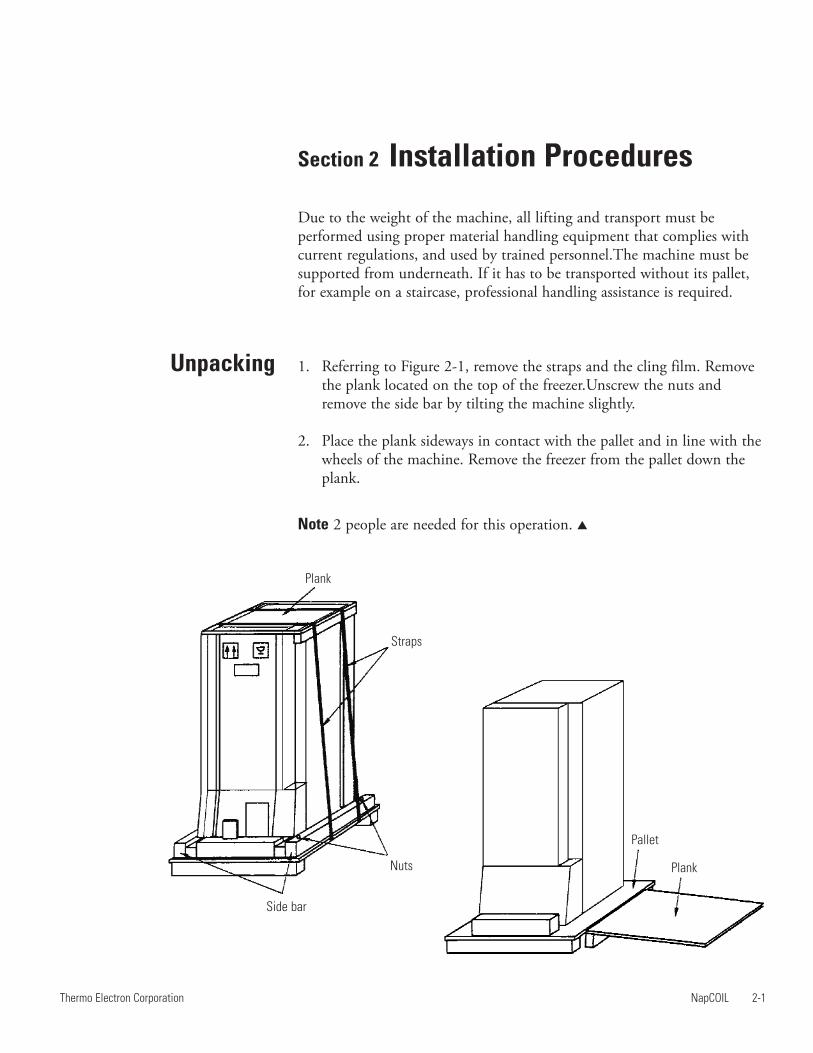
Due to the weight of the machine, all lifting and transport must beperformed using proper material handling equipment that complies withcurrent regulations, and used by trained personnel.The machine must besupported from underneath. If it has to be transported without its pallet,for example on a staircase, professional handling assistance is required.
1. Referring to Figure 2-1, remove the straps and the cling film. Removethe plank located on the top of the freezer.Unscrew the nuts andremove the side bar by tilting the machine slightly.
2. Place the plank sideways in contact with the pallet and in line with thewheels of the machine. Remove the freezer from the pallet down theplank.
Note 2 people are needed for this operation.
Plank
Straps
Nuts
Side bar
Pallet
Plank

Installation
EnvironmentalConditions
2-2 NapCOIL Thermo Electron Corporation
Section 2Installation Procedures
This instrument is designed to operate safely under the followingconditions:
• Indoor use
• Temperature of 5°C to 40°C
• Maximum relative humidity of 80% for temperature up to 31°Cdecreasing linearly to 50% relative humidity at 40°C.
• Maximum altitude of 2000m
• Voltage fluctuations of ±10%
• Over voltage category II
• Pollution degree 2
Maximum performance is assured across the temperature range of 18°C to25°C and maximum relative humidity of 70%.
1. Never transport the machine on its side.
2. Check that no accessories or printed matter are left in the packaging
3. Install the machine in a suitable environment:
To ensure proper ventilation of the cooling system and ensure correctfunctioning of the freezer, it is extremely important not to place anyobject within 20 cm (8 in.) of the front, back or side ventilation grilles.
The room should be well ventilated and must be fitted with amechanical air extraction if the freezer is fitted with the CO2 back-up.The environment must be non-corrosive and the floor must be level.
4. Check that the available electrical voltage is compatible with theinstrument’s voltage.

Start-Up
Connection toElectrical Power
Positioning theLeveling Feet
NapCOIL 2-3Thermo Electron Corporation
Section 2Installation Procedures
Figure 2-2. Leveling Feet
There are two leveling feet at the front of the freezer.
1. Unscrew the leveling feet.
2. Place an anti-skid pad beneath each one (2 anti-skid pads are providedwith the accessories).
3. Using the 19 mm (0.75 in.) box spanner, provided with theaccessories, continue to unscrew the leveling feet until the front of thefreezer is lifted about one millimeter.
4. Check the level of the freezer by opening and shutting the door, thenadjust the height of the feet accordingly.
Remember that in order to respect the electrical safety standards related toprotection of operators against indirect contact, the power supply to theinstrument must be via a power socket fitted with a protection deviceensuring automatic cut-off in the case of an insulation fault. A powersupply fitted with a circuit breaker of the correct rating complies with thisrequirement.
Before starting the freezer, put the fuse in place at the back of the freezer.
On instrument start-up, the display shows the chamber temperature. Thevisual and audible alarms are activated.
During the cooling procedure, the freezer displays the chambertemperature. It takes about 6 hours to cool down the freezer from +20°Cto -80°C.

NapCOIL 3-1Thermo Electron Corporation
Section 3 Specifications
Freezing system . . . . . . . . . . . . . . . . . . . . .NapCOILTemperature control . . . . . . . . . . . . .Analog controlRegulation range . . . . . . . . . . . . . . . .-65°C to -86°CMinimal temperature . . . . . . . . . . . . . . . . . . . .-86°CTemperature control . . . . . . . . . . . . . . . . . . .±0.5°CTemperature uniformity . . . . . . . . . . . . . . . . . . .±4°C
*Without door opening limiter. The unit is shipped without door opening limiter installed. The door openinglimiter has to be installed after unpacking the freezer.
External Dimensions UF400 UF500 UF 650
DimensionsH* x W x D - mm (in.)
1995 x 800 x 800(78.5 x 31.5 x 31.5)
1995 x 800 x 940(78.5 x 31.5 x 37.0)
1995 x 847 x 1080(78.5 x 33.4 x 42.5)
Weight net/packed - kg (lbs.) 240/260 (529/573) 260/280 (573/617) 290/315 (639/694)
Inner Dimensions and Capacity UF400 UF500 UF650
Compartment dimensionsH x W x D - mm (in.)
308 x 550 x 430(12 x 22 x 17)
308 x 550 x 568(12 x 22 x 22)
308 x 597 x 707(12 x 24 x 28)
Chamber dimensionsH x W x D - mm (in.)
1310 x 550 x 490(52 x 22 x 19)
1310 x 550 x 630(52 x 22 x 25)
1310 x 597 x 770(52 x 24 x 30)
Nominal capacity -litres (cubic feet) 355 (12.5) 455 (16.1) 602 (21.3)
Packaging Dimensions UF400 UF500 UF 650
DimensionsH x W x D - mm (in.)
2220 x 940 x 940(87 x 37 x 37)
2220 x 940 x 1080(87 x 37 x 43)
2220 x 990 x 1220(87 x 39 x 48)
Models w ith R508(2nd stage) UF400 UF500 UF 650
230V/50Hz 51500901 51500905 51500912
208V/60Hz 51500902 51500906 51250911

CascadeRefrigeration System
NapCOIL 4-1Thermo Electron Corporation
Section 4 Operating Principles
The refrigeration system is a cascade, air-cooled, hermetically sealed,system.
The refrigeration system consists of 2 refrigeration systems put in cascade.The second stage fluid is evaporated in the chamber using the heat fromthe chamber. The heat is then transferred to the first system at the heatexchanger. The heat transferred to the first system is then transferred to theenvironment at the condenser.
The refrigerants used are R-507 (1st stage), R-508 + R-290 (2nd stage).
Figure 4-1. Refrigeration Diagram
2nd
group1st
group
HP safety deviceCascade
NapCOILcooling coil
Capillary tube Drying filter
HP safety deviceCondenser

High Temperature AlarmSetpoint
Temperature Setpoint
NapCOIL 5-1Thermo Electron Corporation
Section 5 Instructions for Use
A description of control panel components follows. The display shows thefollowing information:
• Measured temperature in 1°C increments
• Set temperature in 1°C increments
Figure 5-1. Control Panel
The freezers are factory preset at -80°C. To modify temperature setpoint:While pressing the key, use the screwdriver shipped with the unit torotate the potentiometer. To check the set point, press the key.
The high temperature alarm setpoint is fixed at 10°C above temperaturesetpoint.
5
Red light for visual alarm
3 digit LED display
Mute key to silence the alarm
Potentiometer to adjusttemperature setpoint
Key for access to thetemperature setpoint

NapCOIL freezers give an alarm signal in the following situations :
• High temperature alarm
• Short circuit on the probe
• Power Failure
In case of an alarm situation, the audible and visible alarms are activated.
In case of an alarm situation, check that the door is properly closed.
To silence the audible alarm, press the key to stop the audible alarm.
Note When there is no alarm condition, check both visual and audiblealarms by pressing the key.
After pressing , the alarm will be reactivated if it has been more thanone hour since was last pressed, or if the original alarm condition hascleared and another alarm condition occurred.
The freezers are fitted with a battery back-up system. This battery powersthe control panel and alarms for 12 hours in case of a power failure.
NapCOIL freezers are fitted with a remote alarm contact. The alarmcontact is activated in the following conditions:
• Power failure
• High temperature alarm
• Short-circuit on the sensor
Figure 5-2. Remote Alarm Contact Figure 5-3. Contact Shown in Alarm Location on Back of Freezer Condition
In an alarm situation, the contact is closed between pins 5 and 7.
These options must be installed by a qualified service engineer.
5-2 NapCOIL Thermo Electron Corporation
Section 5Instructions for Use
Alarm Conditions
Battery
Remote AlarmContact
9.......1
9 8 7 6 5 4 3 2 1

Fuse Information
Power Supply
60Hz Freezer InputCable
Caution For personal safety, this apparatus must be properly grounded.
The power cord provided on this unit is equipped with a three-prong plugwhich mates with a standard three-prong grounding wall receptacle tominimise the possibility of electric shock hazard from this apparatus. If indoubt, the user should have the wall receptacle and circuit checked by aqualified electrician to make sure the receptacle can provide adequatecurrent and is properly grounded. If a standard two-prong wall receptacleis encountered, it is the personal responsibility and obligation of the userto have it replaced with a properly grounded three-prong wall receptacle.
Warning Do not, under any circumstances, cut or remove the third(ground) prong from the power cord. Do not use a two-prong adapterplug.
Wire colors in power cable: black 1 = Line, black 2 = Neutral,Earth/Ground = yellow; green
Please refer to the power supply rating plate on the left side of the externalcabinet.
230V ±10%, 50Hz, 4 Amp, 850W
208-220V ±10%, 60Hz, 4.3 Amp, 850W
115 V ±10%, 60Hz, 8.5 Amp, 850W
Power card F1, 100 mAmp, 5 x 20 mm
Battery F1, 100 mAmp, 5 x 20 mm
Rear panel F2, 500 mAmp, 5 x 20 mm
NapCOIL 5-3Thermo Electron Corporation
Section 5Instructions for Use

Cleaning the CoolingCoil
Section 6 Hazards, Precautions andLimitations of Use
Use gloves to handle frozen samples inside the freezer. Unprotected handsmay get serious frost injuries.
Power to the freezer should be supplied only by a dedicated circuit througha circuit breaker. Do not use a common power source with other electricalappliances.
Warning All servicing on the refrigeration system must be performed by aService Engineer qualified to service Cascade Refrigeration Systems.
The NapCOIL consists of :
• An anodized aluminum plate for the top of the shelf
• A perforated aluminum plate for the bottom of the shelf
• An aluminum cooling coil inserted between
To ensure maximum performance of the freezer, the NapCOIL mustremain clean. As soon as dirt appears on the aluminum, clean the differentaluminum parts using warm water mixed with soap and a nylon brush or asponge. Rinse all parts with clean water. Then dry with a drying cloth.
Caution The use of corrosive chemical substances derived from sodiumhydroxide or potassium hydroxide will damage the shelf.
NapCOIL 6-1Thermo Electron Corporation

Section 7 Servicing and PreventativeMaintenance
All the heat removed from the chamber to keep the samples at -80°C isevacuated through the condenser. To provide maximum heat removal, thecondenser must be kept clean of dust and dirt. For this reason, thecondenser is protected by an air filter. To maintain efficient ventilation ofthe condenser, the filter must be kept clean.
To make cleaning easy, NapCOIL Deep Freezers are fitted with directaccess to the condenser filter.
To clean the filter:
1. Open the ventilation grille located at the bottom of the unit as shownon the drawing.
2. Pull the filter out (affixed with Velcro).
3. Clean the filter with warm water.
4. Dry the filter properly before putting it back in place. Meanwhile, aspare filter can be used in the grille to protect the condenser (Cat N°:86001847).
5. Write the next cleaning date on the label located next to the filter.
Figure 7-1. Condenser Filter Access
NapCOIL 7-1Thermo Electron Corporation
Condenserfilter
Ventilationgrille (open)
Side ventilationgrille
Warm air

Accessories
Fuse Replacement
Chamber Cleaning
Freezer Defrosting
7-2 NapCOIL Thermo Electron Corporation
Section 7Servicing and Preventative Maintenance
The frost that accumulates on the door gasket reduces the airtight seal.This results in an increase of frost inside the chamber and difficulty inkeeping the chamber at the desired temperature. To avoid this, regularlyclean the door gasket.
Clean the walls of the chamber with a surface disinfectant (70% alcohol,2% glutaraldehyde). Avoid chlorinated solutions which might damage theinterior of the freezer.
See Section 6 for the cleaning of aluminum parts.
Changing of the fuse must performed by a qualified engineer to diagnosethe fault before replacing the fuses.
Catalog numbers for CO2 back-up for NapCOIL freezer are 51200715 for120V units, or 51200716 for 208V units.
Stock Number Description3183014 CAJ2432ZSE compressor 60 Hz 1st stage3182985 CAJ2432Z compressor 60 Hz 2nd stage3182906 Starting box 60 Hz 1st stage/2nd stage3182874 Fan 60 Hz3182185 Drying filter3182296 Chamber temperature sensor (PT100)3181943 Door switch3181463 Condenser temperature sensor3172686 Triac3182082 Circuit breaker (230V units)3185206 Circuit breaker 20 Amp (120V units)3181466 Power pcb 208 V-60 Hz3181471 CPU pcb3181462 Battery pcb 2311983168137 Condenser filter kit3181931 Armaflex tape3184900 Power card/Battery fuse3172452 Rear panel fuse
Spare Parts

Thermo Electron CorporationControlled Environment Equipment
www.thermo.com